JP6845809B2 - Control unit for flexible endoscopes - Google Patents
Control unit for flexible endoscopesDownload PDFInfo
- Publication number
- JP6845809B2 JP6845809B2JP2017560595AJP2017560595AJP6845809B2JP 6845809 B2JP6845809 B2JP 6845809B2JP 2017560595 AJP2017560595 AJP 2017560595AJP 2017560595 AJP2017560595 AJP 2017560595AJP 6845809 B2JP6845809 B2JP 6845809B2
- Authority
- JP
- Japan
- Prior art keywords
- interface
- control unit
- unit according
- drive mechanism
- shaft
- Prior art date
- Legal status (The legal status is an assumption and is not a legal conclusion. Google has not performed a legal analysis and makes no representation as to the accuracy of the status listed.)
- Active
Links
Images


Classifications
- A—HUMAN NECESSITIES
- A61—MEDICAL OR VETERINARY SCIENCE; HYGIENE
- A61B—DIAGNOSIS; SURGERY; IDENTIFICATION
- A61B1/00—Instruments for performing medical examinations of the interior of cavities or tubes of the body by visual or photographical inspection, e.g. endoscopes; Illuminating arrangements therefor
- A61B1/005—Flexible endoscopes
- A61B1/0051—Flexible endoscopes with controlled bending of insertion part
- A61B1/0052—Constructional details of control elements, e.g. handles
- A—HUMAN NECESSITIES
- A61—MEDICAL OR VETERINARY SCIENCE; HYGIENE
- A61B—DIAGNOSIS; SURGERY; IDENTIFICATION
- A61B1/00—Instruments for performing medical examinations of the interior of cavities or tubes of the body by visual or photographical inspection, e.g. endoscopes; Illuminating arrangements therefor
- A61B1/00131—Accessories for endoscopes
- A61B1/00133—Drive units for endoscopic tools inserted through or with the endoscope
- A—HUMAN NECESSITIES
- A61—MEDICAL OR VETERINARY SCIENCE; HYGIENE
- A61B—DIAGNOSIS; SURGERY; IDENTIFICATION
- A61B1/00—Instruments for performing medical examinations of the interior of cavities or tubes of the body by visual or photographical inspection, e.g. endoscopes; Illuminating arrangements therefor
- A61B1/00002—Operational features of endoscopes
- A61B1/00039—Operational features of endoscopes provided with input arrangements for the user
- A61B1/00042—Operational features of endoscopes provided with input arrangements for the user for mechanical operation
- A—HUMAN NECESSITIES
- A61—MEDICAL OR VETERINARY SCIENCE; HYGIENE
- A61B—DIAGNOSIS; SURGERY; IDENTIFICATION
- A61B1/00—Instruments for performing medical examinations of the interior of cavities or tubes of the body by visual or photographical inspection, e.g. endoscopes; Illuminating arrangements therefor
- A61B1/00064—Constructional details of the endoscope body
- A61B1/00066—Proximal part of endoscope body, e.g. handles
- A—HUMAN NECESSITIES
- A61—MEDICAL OR VETERINARY SCIENCE; HYGIENE
- A61B—DIAGNOSIS; SURGERY; IDENTIFICATION
- A61B1/00—Instruments for performing medical examinations of the interior of cavities or tubes of the body by visual or photographical inspection, e.g. endoscopes; Illuminating arrangements therefor
- A61B1/00147—Holding or positioning arrangements
- A61B1/0016—Holding or positioning arrangements using motor drive units
- A—HUMAN NECESSITIES
- A61—MEDICAL OR VETERINARY SCIENCE; HYGIENE
- A61B—DIAGNOSIS; SURGERY; IDENTIFICATION
- A61B1/00—Instruments for performing medical examinations of the interior of cavities or tubes of the body by visual or photographical inspection, e.g. endoscopes; Illuminating arrangements therefor
- A61B1/04—Instruments for performing medical examinations of the interior of cavities or tubes of the body by visual or photographical inspection, e.g. endoscopes; Illuminating arrangements therefor combined with photographic or television appliances
- A61B1/045—Control thereof
- A—HUMAN NECESSITIES
- A61—MEDICAL OR VETERINARY SCIENCE; HYGIENE
- A61B—DIAGNOSIS; SURGERY; IDENTIFICATION
- A61B17/00—Surgical instruments, devices or methods
- A61B17/28—Surgical forceps
- A61B17/29—Forceps for use in minimally invasive surgery
- A—HUMAN NECESSITIES
- A61—MEDICAL OR VETERINARY SCIENCE; HYGIENE
- A61M—DEVICES FOR INTRODUCING MEDIA INTO, OR ONTO, THE BODY; DEVICES FOR TRANSDUCING BODY MEDIA OR FOR TAKING MEDIA FROM THE BODY; DEVICES FOR PRODUCING OR ENDING SLEEP OR STUPOR
- A61M25/00—Catheters; Hollow probes
- A61M25/01—Introducing, guiding, advancing, emplacing or holding catheters
- A61M25/0105—Steering means as part of the catheter or advancing means; Markers for positioning
- A61M25/0133—Tip steering devices
- A61M25/0136—Handles therefor
- A—HUMAN NECESSITIES
- A61—MEDICAL OR VETERINARY SCIENCE; HYGIENE
- A61B—DIAGNOSIS; SURGERY; IDENTIFICATION
- A61B17/00—Surgical instruments, devices or methods
- A61B17/00234—Surgical instruments, devices or methods for minimally invasive surgery
- A61B2017/00292—Surgical instruments, devices or methods for minimally invasive surgery mounted on or guided by flexible, e.g. catheter-like, means
- A61B2017/003—Steerable
- A—HUMAN NECESSITIES
- A61—MEDICAL OR VETERINARY SCIENCE; HYGIENE
- A61B—DIAGNOSIS; SURGERY; IDENTIFICATION
- A61B17/00—Surgical instruments, devices or methods
- A61B17/00234—Surgical instruments, devices or methods for minimally invasive surgery
- A61B2017/00292—Surgical instruments, devices or methods for minimally invasive surgery mounted on or guided by flexible, e.g. catheter-like, means
- A61B2017/0034—Surgical instruments, devices or methods for minimally invasive surgery mounted on or guided by flexible, e.g. catheter-like, means adapted to be inserted through a working channel of an endoscope
- A—HUMAN NECESSITIES
- A61—MEDICAL OR VETERINARY SCIENCE; HYGIENE
- A61B—DIAGNOSIS; SURGERY; IDENTIFICATION
- A61B17/00—Surgical instruments, devices or methods
- A61B2017/00367—Details of actuation of instruments, e.g. relations between pushing buttons, or the like, and activation of the tool, working tip, or the like
- A61B2017/00398—Details of actuation of instruments, e.g. relations between pushing buttons, or the like, and activation of the tool, working tip, or the like using powered actuators, e.g. stepper motors, solenoids
- A—HUMAN NECESSITIES
- A61—MEDICAL OR VETERINARY SCIENCE; HYGIENE
- A61B—DIAGNOSIS; SURGERY; IDENTIFICATION
- A61B17/00—Surgical instruments, devices or methods
- A61B2017/0042—Surgical instruments, devices or methods with special provisions for gripping
- A61B2017/00424—Surgical instruments, devices or methods with special provisions for gripping ergonomic, e.g. fitting in fist
- A—HUMAN NECESSITIES
- A61—MEDICAL OR VETERINARY SCIENCE; HYGIENE
- A61B—DIAGNOSIS; SURGERY; IDENTIFICATION
- A61B17/00—Surgical instruments, devices or methods
- A61B17/28—Surgical forceps
- A61B17/29—Forceps for use in minimally invasive surgery
- A61B17/2909—Handles
- A61B2017/291—Handles the position of the handle being adjustable with respect to the shaft
Landscapes
- Health & Medical Sciences (AREA)
- Life Sciences & Earth Sciences (AREA)
- Surgery (AREA)
- Engineering & Computer Science (AREA)
- Veterinary Medicine (AREA)
- Public Health (AREA)
- General Health & Medical Sciences (AREA)
- Animal Behavior & Ethology (AREA)
- Biomedical Technology (AREA)
- Heart & Thoracic Surgery (AREA)
- Biophysics (AREA)
- Molecular Biology (AREA)
- Nuclear Medicine, Radiotherapy & Molecular Imaging (AREA)
- Medical Informatics (AREA)
- Physics & Mathematics (AREA)
- Radiology & Medical Imaging (AREA)
- Pathology (AREA)
- Optics & Photonics (AREA)
- Pulmonology (AREA)
- Anesthesiology (AREA)
- Hematology (AREA)
- Ophthalmology & Optometry (AREA)
- Mechanical Engineering (AREA)
- Endoscopes (AREA)
- Instruments For Viewing The Inside Of Hollow Bodies (AREA)
- Surgical Instruments (AREA)
Description
Translated fromJapanese本発明は、フレキシブル内視鏡に取り付け可能でありかつ単一の手を使用して先端の変位(deflection)と作用通路に配置される器具の両方を制御するために使用されることができる制御ユニットに関する。 The present invention is a control that can be attached to a flexible endoscope and can be used to control both tip displacement and instruments placed in the action passage using a single hand. Regarding the unit.
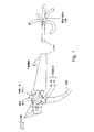
フレキシブル内視鏡(図1)は、制御ヘッド及び操作可能な先端を有するフレキシブルシャフトからなる。ヘッドは、「臍帯」コードを介して光源に接続され、それを通して空気や水を送ったり、吸引などを行なう他の管を進める。作用通路は、診断又は治療器具の通過のために使用される。 The flexible endoscope (FIG. 1) consists of a flexible shaft with a control head and an operable tip. The head is connected to the light source via an "umbilical cord" cord through which it advances other tubes that carry air, water, suction, and so on. The passage of action is used for the passage of diagnostic or therapeutic instruments.
二つの並んで装着された回転可能なつまみは、制御ヘッドの側部上に装着され、シャフト先端の上/下及び右/左の移動のために使用される。 Two side-by-side rotatable knobs are mounted on the sides of the control head and are used for up / down and right / left movement of the shaft tip.
熟練した手では、これらのつまみは、いかなる方向にも先端の角度を制御するために使用されることができるが、かかる制御は、両手の使用を要求し、いかなる他の器具(例えば、作用通路を通して配置された診断又は治療器具)に対する同時制御も不可能にする。この制限を覆すためには、標準的なフレキシブル内視鏡の制御つまみは、摩擦ブレーキシステムを含み、従って先端は、いかなる所望の位置にも一時的に固定されることができ、かくして操作者が他の器具を制御することが自由になる。 With a skilled hand, these knobs can be used to control the angle of the tip in any direction, but such control requires the use of both hands and any other instrument (eg, action passage). Simultaneous control over diagnostic or therapeutic instruments placed through is also not possible. To overcome this limitation, standard flexible endoscope control knobs include a friction braking system, so the tip can be temporarily fixed in any desired position, thus allowing the operator. You are free to control other instruments.
かかる解決策は、内視鏡先端が特定の位置でロックされるときに作用通路を通して配置された診断又は治療器具の制御を可能にするが、それは、器具に対する制御を維持しながら内視鏡先端を再配置することを可能としない。後者は、手順として内視鏡カメラ及び器具を同時に操作することを要求する場合に重要である。 Such a solution allows control of a diagnostic or therapeutic instrument placed through a passage of action when the endoscopic tip is locked in a particular position, which allows control of the endoscopic tip while maintaining control over the device. Does not allow relocation. The latter is important when the procedure requires simultaneous operation of the endoscopic camera and instrument.
標準的なフレキシブル内視鏡のこの制限に対処するために、本発明者は、操作者が片手を使用して作用通路を通して配置された器具並びにフレキシブル内視鏡の先端を制御することを可能にする制御ユニットを考案した。 To address this limitation of standard flexible endoscopes, the inventor allows an operator to use one hand to control an instrument placed through a passage of action as well as the tip of a flexible endoscope. I devised a control unit to do.
本発明の一態様によれば、二つの回転可能なつまみを介して変位可能なシャフトを有する内視鏡に取り付け可能な制御ユニットであって、以下のものを含む制御ユニットが提供される:
(a)制御ユニットのハウジングに取り付けられたピボット支持体上に取り付けられかつ手の掌によって係合可能な第一インターフェースを含むユーザーインターフェース;及び
(b)前記ユーザーインターフェースを介して操作可能な駆動ユニットであって、二つの回転可能なつまみを係合し、それによってユーザーが前記第一インターフェースを介して内視鏡のシャフトの変位を制御することができる第一駆動機構を含む駆動ユニット。According to one aspect of the invention, there is provided a control unit that is attachable to an endoscope having a shaft that is displaceable via two rotatable knobs and includes:
(A) A user interface including a first interface mounted on a pivot support mounted on the housing of the control unit and engageable by the palm of the hand; and (b) a drive unit operable via said user interface. A drive unit comprising a first drive mechanism that engages two rotatable knobs, whereby the user can control displacement of the endoscope shaft via the first interface.
以下に記載される本発明の好ましい実施形態におけるさらなる特徴によれば、二つの回転可能なつまみのうち第一の回転可能なつまみは、シャフトの上/下の変位を制御し、二つの回転可能なつまみのうち第二の回転可能なつまみは、シャフトの左/右の変位を制御し、さらに前記第一インターフェースは、シャフトの上/下と左/右の両方の変位を制御する。 According to a further feature in a preferred embodiment of the invention described below, the first of the two rotatable knobs controls the displacement of the shaft up / down and the two rotatable knobs. The second rotatable knob of the knob controls the left / right displacement of the shaft, and the first interface controls both the top / bottom and left / right displacement of the shaft.
記載された好ましい実施形態におけるさらなる特徴によれば、前記第一駆動機構は、前記第一インターフェースを介して操作可能な少なくとも一つのモーターを含む。 According to a further feature of the preferred embodiments described, the first drive mechanism comprises at least one motor that can be operated via the first interface.
記載された好ましい実施形態におけるさらなる特徴によれば、前記少なくとも一つのモーターは、二つのつまみを操作する。 According to the further features of the preferred embodiments described, the at least one motor operates two knobs.
記載された好ましい実施形態におけるさらなる特徴によれば、前記第一駆動機構は、前記少なくとも一つのモーターと二つのつまみの間に介在された一組の歯車を含む。 According to a further feature in the preferred embodiments described, the first drive mechanism comprises a set of gears interposed between the at least one motor and the two knobs.
記載された好ましい実施形態におけるさらなる特徴によれば、前記駆動ユニットは、内視鏡の作用通路を通して配置可能な手術器具の手動操作可能な端を係合するための第二駆動機構をさらに含む。 According to a further feature of the preferred embodiments described, the drive unit further includes a second drive mechanism for engaging a manually operable end of a surgical instrument that can be placed through the action passage of the endoscope.
記載された好ましい実施形態におけるさらなる特徴によれば、制御ユニットは、前記第一インターフェースに旋回可能に取り付けられかつ前記手の一つ以上の指によって係合可能な第二インターフェースであって、前記第二駆動機構を通して前記手術器具を操作するための第二インターフェースをさらに含む。 According to a further feature of the preferred embodiment described, the control unit is a second interface that is swivelly attached to the first interface and engageable by one or more fingers of the hand. It further includes a second interface for manipulating the surgical instrument through the drive mechanism.
記載された好ましい実施形態におけるさらなる特徴によれば、制御ユニットは、前記第一インターフェースに旋回可能に取り付けられ、かつ前記掌が前記第一インターフェースと係合されるときに前記手の甲に拘束力を付与するために弾性変形することができる要素を有する拘束具をさらに含む。 According to a further feature of the preferred embodiment described, the control unit is swivelably attached to the first interface and imparts restraint to the back of the hand when the palm is engaged with the first interface. Further includes restraints having elements that can be elastically deformed to do so.
記載された好ましい実施形態におけるさらなる特徴によれば、前記ピボット支持体は、ジンバルを入れられている。 According to the further features of the preferred embodiments described, the pivot support is gimbalized.
記載された好ましい実施形態におけるさらなる特徴によれば、前記第二インターフェースは、前記手の親指及び人指し指を介して同時に操作可能なパッドを含む。 According to a further feature of the preferred embodiment described, the second interface includes a pad that can be operated simultaneously via the thumb and index finger of the hand.
記載された好ましい実施形態におけるさらなる特徴によれば、前記第二駆動機構は、サーボ機構を含む。 According to the further features of the preferred embodiments described, the second drive mechanism includes a servo mechanism.
記載された好ましい実施形態におけるさらなる特徴によれば、制御ユニットは、遠隔装置を無線制御するための第三インターフェースをさらに含む。 According to the further features of the preferred embodiments described, the control unit further includes a third interface for wirelessly controlling the remote device.
記載された好ましい実施形態におけるさらなる特徴によれば、前記手術器具は、前記第二インターフェースを介して制御可能なエフェクター端及び操縦可能なシャフトを含む。 According to the additional features of the preferred embodiments described, the surgical instrument includes an effector end that can be controlled via the second interface and a maneuverable shaft.
本発明は、操作者が片手によって内視鏡並びにそこに装着された器具を制御することができる、フレキシブル内視鏡のための制御ユニットを提供することによって現在公知の構成の欠点を首尾良く対処する。 The present invention successfully addresses the shortcomings of currently known configurations by providing a control unit for a flexible endoscope that allows an operator to control the endoscope and the instruments mounted therein with one hand. To do.
別途定義されない限り、本明細書で使用されるすべての技術的用語および/または科学的用語は、本発明が属する技術分野の当業者によって一般に理解されるのと同じ意味を有する。本明細書に記載される方法および材料と類似または同等である方法および材料を本発明の実施または試験において使用することができるが、例示的な方法および/または材料が下記に記載される。矛盾する場合には、定義を含めて、本特許明細書が優先する。加えて、材料、方法および実施例は例示にすぎず、限定であることは意図されない。 Unless otherwise defined, all technical and / or scientific terms used herein have the same meaning as commonly understood by one of ordinary skill in the art to which the present invention belongs. Methods and materials that are similar or equivalent to the methods and materials described herein can be used in the practice or testing of the present invention, but exemplary methods and / or materials are described below. In case of conflict, the patent specification, including the definition, shall prevail. In addition, the materials, methods and examples are exemplary only and are not intended to be limiting.
本発明は、添付図面を参照して例示としてのみここに説明される。特に詳細に図面を参照して、示されている詳細が例示として本発明の好ましい実施態様を例示考察することだけを目的としており、本発明の原理や概念の側面の最も有用でかつ容易に理解される説明であると考えられるものを提供するために提示していることを強調するものである。この点について、本発明を基本的に理解するのに必要である以上に詳細に本発明の構造の詳細は示さないが、図面について行う説明によって本発明のいくつもの形態を実施する方法は当業者には明らかになるであろう。 The present invention is described herein by way of example only with reference to the accompanying drawings. In particular, with reference to the drawings in detail, the details shown are merely intended to exemplify and consider preferred embodiments of the invention by way of example, and the most useful and easily understood aspects of the principles and concepts of the invention. It emphasizes that it is presented to provide what is believed to be the explanation given. In this regard, although no details of the structure of the invention will be given in more detail than necessary for a basic understanding of the invention, those skilled in the art will appreciate how to implement any of the embodiments of the invention by the description given in the drawings. Will become clear.
本発明は、フレキシブル内視鏡の先端の動き、並びにその作用通路を通して配置された器具の動き及び機能を制御するために使用されることができる制御ユニットを持つ。 The present invention has a control unit that can be used to control the movement of the tip of a flexible endoscope, as well as the movement and function of an instrument placed through its working path.
本発明の原理および操作は、図面および付随する説明を参照してより良く理解されることができる。 The principles and operations of the present invention can be better understood with reference to the drawings and accompanying description.
本発明の少なくとも1つの実施形態を詳細に説明する前に、本発明は、その適用において、下記の説明に示されるか、または図面によって例示される構成要素の構造及び配置の細部に限定されないことを理解しなければならない。本発明は、他の実施形態が可能であり、あるいは、様々な方法で実施または実行される。また、本明細書中において用いられる表現法および用語法は説明のためであって、限定として見なされるべきでないことを理解しなければならない。 Prior to elaborating on at least one embodiment of the invention, the invention is not limited in its application to the details of the structure and arrangement of the components shown in the following description or exemplified by the drawings. Must be understood. Other embodiments are possible, or the invention is practiced or practiced in various ways. It should also be understood that the expressions and terminology used herein are for illustration purposes only and should not be considered as limitations.
内視鏡の手順は、内視鏡とその関連器具(例えば、作用通路器具)の両方を制御することを医師に要求する。標準的なフレキシブル内視鏡は、先端変位制御のために両手を必要とするので、医師は、内視鏡、及びその作用通路を通して配置された手術/治療器具の両方を同時に制御することができない。 The endoscopic procedure requires the physician to control both the endoscope and its associated instruments (eg, action passage instruments). Since standard flexible endoscopes require both hands for tip displacement control, physicians cannot simultaneously control both the endoscope and the surgical / therapeutic instruments placed through its passage of action. ..
本発明を実施に移すとき、本発明者は、標準的なフレキシブル内視鏡に取り付けられることができ、かつ医師が片手を使用して内視鏡と診断/治療器具(並びに他の追加の周辺器具)の両方を制御することを可能にする制御ユニットを考案した。ここにさらに記載されるように、本発明の制御ユニットは、内視鏡制御ヘッドに対する変更なしにいかなるフレキシブル内視鏡の上にも組み込むことができる。 When implementing the present invention, the inventor can be attached to a standard flexible endoscope, and the physician can use one hand to use the endoscope and diagnostic / therapeutic instruments (as well as other additional perimeters). We devised a control unit that makes it possible to control both of the appliances). As further described herein, the control unit of the present invention can be mounted on any flexible endoscope without modification to the endoscope control head.
従って、本発明の一態様によれば、標準的なフレキシブル内視鏡のための制御ユニットが提供される。ここで使用される「標準的なフレキシブル内視鏡」は、回転可能なつまみを介して制御可能な変位可能先端を有するいかなる内視鏡も包含する。かかる内視鏡は、関心の解剖学的領域を撮像するためのカメラを含むことが好ましい。 Therefore, according to one aspect of the invention, a control unit for a standard flexible endoscope is provided. The "standard flexible endoscope" used herein includes any endoscope having a displaceable tip that can be controlled via a rotatable knob. Such an endoscope preferably includes a camera for imaging the anatomical region of interest.
制御ユニットは、ユーザーインターフェースを取り付けられた駆動ユニットを含む。以下でさらに記載されるように、インターフェースは、ユーザーの片手によって操作され、制御ユニット内のモーター及び歯車/レバー/ワイヤーを作動し、それによって内視鏡、及びそれを通して配置された診断/治療器具を制御する。 The control unit includes a drive unit fitted with a user interface. As further described below, the interface is operated by one hand of the user to operate the motors and gears / levers / wires in the control unit, thereby the endoscope and the diagnostic / therapeutic instruments placed through it. To control.
ユーザーインターフェースは、内視鏡先端の変位及び診断/治療器具に対して別個の制御を持つ。ユーザーインターフェースは、制御ユニットのハウジングに取り付けられたピボット支持体(例えばジンバルを入られている)に装着される第一インターフェースを含む。第一インターフェースは、手の掌によって係合可能であり、ユーザーが駆動ユニットの第一駆動機構を介していかなる方向にも内視鏡先端の変位を制御することを可能にする。 The user interface has separate control over the displacement of the endoscope tip and diagnostic / therapeutic instruments. The user interface includes a first interface mounted on a pivot support (eg, containing a gimbal) attached to the housing of the control unit. The first interface can be engaged by the palm of the hand, allowing the user to control the displacement of the endoscope tip in any direction via the first drive mechanism of the drive unit.
ユーザーの掌を第一インターフェースに対してその操作中に維持するために、制御ユニットは、拘束具をさらに含む。拘束具は、第一インターフェースの一部を形成し、かつ掌が第一インターフェースと係合されるときに手の甲(背)に拘束力を付与するために弾性変形することができる要素を含む。この拘束具が手の甲に係合するとき、その要素は、弾性変形し、手の甲に下方向の力を付与し、かくして第一インターフェースに対して手を維持し、このインターフェースの正確な制御を可能にし、ユーザーが内視鏡を引き寄せることを可能にする。 The control unit further includes a restraint to maintain the user's palm against the first interface during its operation. The restraint comprises an element that forms part of the first interface and can be elastically deformed to impart a binding force to the back of the hand (back) when the palm is engaged with the first interface. When this restraint engages the back of the hand, the element elastically deforms, exerting a downward force on the back of the hand, thus maintaining the hand against the first interface and allowing precise control of this interface. , Allows the user to pull the endoscope.
制御ユニットはまた、第二インターフェースを含み、第二インターフェースは、第一インターフェースに旋回可能に取り付けられ、かつ手の一つ以上の指によって係合可能である。第二インターフェースは、作用通路を通して配置されかつ駆動ユニットの第二駆動機構に取り付けられた器具の操作を制御する。第二インターフェースは、器具のエフェクター端を制御したり(例えば把持器の開閉)、そのシャフトの回転、並進、及び/又はその操縦可能部分の変位が可能である。 The control unit also includes a second interface, which is swivelly attached to the first interface and engageable by one or more fingers of the hand. The second interface controls the operation of the instrument arranged through the action passage and attached to the second drive mechanism of the drive unit. The second interface can control the effector end of the instrument (eg, opening and closing the gripper), rotate and translate its shaft, and / or displace its maneuverable portion.
本発明のユーザーインターフェースは、三つの別個の肢関節及び筋群の動きによってこれらの三つの機能を提供する:
(i)内視鏡は、腕の動き(主に肘及び/又は肩関節まわり)によって身体に対して上下及び左右に動かされる。
(ii)内視鏡のシャフトは、手の動き(主に手首関節のまわり)によって変位される。これは、第一インターフェースを傾けることによって達成される。
(iii)作用通路器具は、指の動き(主に指関節間及び中手指関節のまわり)によって作動される。指の動きは、器具のエフェクター端を操作したり、シャフトを並進及び回転したり、及び/又はシャフトの操縦可能な部分を変位するために使用されることができる。The user interface of the present invention provides these three functions by the movement of three separate limb joints and muscle groups:
(I) The endoscope is moved up and down and left and right with respect to the body by the movement of the arm (mainly around the elbow and / or the shoulder joint).
(Ii) The shaft of the endoscope is displaced by the movement of the hand (mainly around the wrist joint). This is achieved by tilting the first interface.
(Iii) The action passage device is actuated by finger movements (mainly between the knuckles and around the knuckles). Finger movements can be used to manipulate the effector ends of the device, translate and rotate the shaft, and / or displace the maneuverable portion of the shaft.
上で述べたように、本発明の制御ユニットは、内視鏡の制御つまみに係合し、それによってこれらのつまみによって内視鏡シャフトの変位を制御する。かかる機能性を与えるために幾つかのアプローチが使用されることができる。例えば、ユーザーインターフェースは、インターフェースの動きをつまみの回転に変換する歯車、レバー、及び/又はワイヤーを含む駆動機構を通して制御つまみに連結されることができる。駆動機構は、簡単な機械的「連結」であることができ、又はそれは、微制御を可能にし、かつつまみ回転のために必要とされるインターフェースの力を減少するために一つ又は複数のモーター/サーボ機構を含むことができる。 As mentioned above, the control unit of the present invention engages with the control knobs of the endoscope, thereby controlling the displacement of the endoscope shaft. Several approaches can be used to provide such functionality. For example, a user interface can be connected to a control knob through a drive mechanism that includes gears, levers, and / or wires that convert the movement of the interface into rotation of the knob. The drive mechanism can be a simple mechanical "linkage", or it allows fine control and one or more motors to reduce the interface force required for pinch rotation. / Servo mechanism can be included.
図2a−6aは、制御ユニット10としてここで言及される本発明の制御ユニットの一実施形態を示す。制御ユニット10は、インターフェースでの使用者の手及び指の動きを内視鏡シャフトの変位及びその作用通路を通して与えられる器具の操作に伝達するためのモーター及びサーボ機構を利用する。 2a-6a show an embodiment of the control unit of the present invention referred to herein as the
図2a−2bは、内視鏡12を取り付けられた制御ユニット10を示す。制御ユニット10は、ユーザーインターフェース14を含み、ユーザーインターフェース14は、掌インターフェース16、甲インターフェース17、及び指インターフェース18を含む。インターフェース14は、以下により詳細に記載されるだろう。制御ユニット10はまた、掌インターフェース16の動きを内視鏡12のつまみ22及び22′(図2b)の回転に変換するための第一駆動機構20を含む。駆動機構20は、電気機械装置であり、それは、つまみ22及び22′を回転するためにモーター及び歯車を利用する。 2a-2b shows the
制御ユニット10は、指インターフェース18の動きを内視鏡12の作用通路を通して与えられた器具の操作に変換するための第二駆動機構24をさらに含む。駆動機構24は、器具の手動操作端を操作するための一つ以上のモーター/サーボ機構及び歯車を含む電気機械装置である。 The
ユーザーインターフェース14は、(内視鏡カメラ画像を表示するための)モニター、(手順に関するファイルを表示するための)コンピューター、又は照明を含む周辺機器に対する無線(WiFi,BT)制御を可能にするボタン及びレバーを含む追加のインターフェース要素を含むことができる。 The
図2bは、掌インターフェース16がつまみ22の回転を制御することを可能にする歯車群30及びチップ32を示すためにハウジングの一部を除去した制御ユニット10を示す。 FIG. 2b shows a
チップ32は、ユーザーインターフェース14に電気的に接続され、そこから位置センサー情報を受ける。この情報は、次いでチップ32によって駆動機構20及び24のための命令信号に変換される。チップ32はまた、医師がインターフェース14を介して周辺装置を制御することを可能にするために無線通信モードによって外部装置に接続されることができる。 The
図3は、第一駆動機構20をより詳細に示す。歯車42及び44(右に別個に示される)は、造形された穴46及び48をそれぞれ有し、内視鏡12のつまみ22′及び22のそれぞれの形状を相補する。歯車42は、つまみ22の羽根のまわりに固定され、一方、歯車44は、つまみ22′のまわりに固定される。ウォーム歯車50は、歯車42に連結され、ウォーム歯車52は、歯車44に連結される。 FIG. 3 shows the
歯車54は、ウォーム歯車50のシャフト56に固定され、モーター62によって駆動される歯車60に係合する。歯車64は、ウォーム歯車52のシャフト66(明確化のためにそこからはずされて示される)に固定され、モーター72によって駆動される歯車70に係合する。 The
チップ32(図2b)が掌インターフェース16の配向の変化を検出するとき、信号がモーター62及び/又は72に送られ、相互接続する歯車を通してつまみ22及び/又は22′を作動する。 When the tip 32 (FIG. 2b) detects a change in orientation of the
つまみ22及び/又は22′の各々は、別個の平面上で遠位端を関節運動する。フレキシブル内視鏡の遠位端の関節接合面は、直交し、従ってフレキシブル管の遠位端の組み合わされる動きは、空間関節運動を生み出し、医師がそれを所望の配向に進路決定することを可能にする。 Each of the
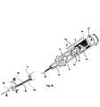
図4a−4bは、インターフェース18によって作動される第二駆動機構24をより詳細に示す。駆動機構24は、ハウジング70を含み、ハウジング70は、首領域72及び配向羽根74を含む。羽根74は、ハウジング70が自由に回転するのを防止するために制御ユニット10においてそれぞれの溝に係合する。ハウジング70は、二つの半分体から作られることができ、それらは、ねじ、嵌め込みなどによって取り付けられる。 4a-4b show in more detail the
図4bは、駆動機構24の内部構成要素、及び遠位開口115から突出する器具80のシャフト82を示す内視鏡12の遠位端を示す。駆動機構24の内側の構成要素の動きは、R,L及びCによって示されるようにシャフト82及び把持器83の動きに変換される。 FIG. 4b shows the internal components of the
内視鏡12の作用通路13を通して配置可能な診断又は手術器具80の手動制御端を保持するために係合要素76が設計される。この実施形態では、把持器83のエフェクター端を有する器具80(図4a)のループ型の指支え78を保持するための要素76が構成され、一方、器具80のバレル型の指支え79を保持するための開口77が設計される。指支え79に対する指支え78の動きは、器具80のあご部83を開閉する。 The engaging
器具80は、図4bに示されるように支え76及び79、及びハウジング70における内腔を通って首領域72の開口から出て配置されるシャフト82を伴なって配置される。 The
駆動機構24は、四つの別個の動きが可能であり、器具80(R)を回転し、器具80のシャフト82を前方及び後方に動かし115(L)、及び把持器83(C)のあご部を開閉する。 The
把持器83のあご部を開閉するために、駆動機構24は、シリンダー87内のねじ穴にねじ86を入れたり出したりするためのモーター84を含む。モーター84のシャフトが回転するとき、ねじ86は、シリンダー87内に回転して入り、それによって指支え79(C)に対して指支え76をスライドする。 In order to open and close the jaw portion of the
シリンダー87(L)の前方及び後方の動きは、組立体89を動かし、従って把持器83を作動せずに器具80全体を動かす。かかる動きは、モーター84又は別のモーターによって制御されることができる。 The forward and backward movement of the cylinder 87 (L) moves the assembly 89 and thus the
追加のモーターは、シリンダー87を回転することができ、それによって駆動機構24内で器具80を回転する。 An additional motor can rotate the
器具80は、その一部を操縦するための制御ワイヤーを有し、器具80はまた、駆動機構24に接続されることができる。かかる器具の制御ワイヤーは、例えば歯車及び棒を介して駆動機構24の一つ以上のモーターに連結され、モーターが一つ以上の制御ワイヤーを選択的に引いたり、器具の操縦可能部分を変位することを可能にすることができる。 The
上で述べたように、本発明のユーザーインターフェース14は、片手を使用した器具操作及び内視鏡先端の変位に対する同時制御を可能にする。 As mentioned above, the
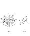
図5a−5bは、ユーザーインターフェース14をより詳細に記載する。ユーザーインターフェース14は、軸100及び101のまわりに同時にピッチ(P)及びヨー(Y)方向に動かすことができる掌インターフェース16を含む。これらの回転は、ボールジョイント/ジンバルピボット点、及びベース102の上に位置されるセンサー機構(図示せず)に対してなされる。関節運動を継ぎ目なく制御するため、医師は、上で記載したような手の甲を支持する甲インターフェース17で図5bに示されるようにインターフェース14内に手(H)を置く。内視鏡12の遠位先端118の得られる動きは、図6aに示される。掌インターフェース16のホーム(中立)位置は、遠位先端118の直線方向の位置(L)に相当し、一方、掌インターフェース16のピッチ(P)及びヨー(Y)は、矢印によって示されるように先端118の変位をもたらす。 5a-5b describes the
器具80のシャフト82に対する制御は、指インターフェース18によって実施される。インターフェース18のパッド106は、あご部の開閉を制御するために使用される。図5bに示されるように、医師の人指し指及び親指は、パッド106に係合し、パッド106を押したり離したりすることによってあご部の開閉を可能にする。あご部の回転は、ベース113のまわりにハウジング108を回転することによって制御される。インターフェース18は、医師が二つの指を使用してあご部の回転とそれらの開閉の両方を同時に制御することを可能にする。ハウジング108はまた、ベース113に対して引いたり押したりすることができる。ハウジング108のベース113に位置される直線状センサーは、医師が、シャフト82の遠位端が作用通路の遠位開口115(図6b)から突出する距離を制御することを可能にする。直線状センサーは、三つの接点(前方、後方、及び中立)を有する簡単なマイクロスイッチであることができ、又は直線方向の移動距離を測定するいかなるアナログ又はデジタルセンサーであることができる。 Control of the
図6bは、ハウジング108の回転、パッド106の押したり離したり、及びハウジング108の押したり引いたりにそれぞれ反応した器具80のシャフト回転(R)、把持器開閉(C)、及びシャフト並進(L)を示す。 FIG. 6b shows the shaft rotation (R) of the
本明細書中で使用される用語「約」は、±10%を示す。 The term "about" as used herein refers to ± 10%.
本発明の追加の目的、利点、及び新規な特徴は、限定されることを意図されない以下の実施例の精査により当業者に明らかになるだろう。 Additional objectives, advantages, and novel features of the present invention will be apparent to those skilled in the art by scrutiny of the following examples not intended to be limited.
次に下記の実施例が参照されるが、下記の実施例は、上記の説明と一緒に、本発明を非限定様式で例示する。 The following examples will then be referred to, which, along with the above description, illustrate the invention in a non-limiting manner.
プロトタイプ制御ユニットの試験
本制御ユニットのプロトタイプが標準的なフレキシブル内視鏡で組み立てられ、試験された。プロトタイプは、掌インターフェースによって内視鏡操縦を駆動するための第一駆動機構、及び把持器具の回転及び延長/引込並びにそのあご部の作動のための第二駆動機構を収容する3D印刷体を含んでいた。Prototype Control Unit Testing A prototype of this control unit was assembled and tested with a standard flexible endoscope. The prototype includes a 3D printer that houses a first drive mechanism for driving the endoscope maneuver by a palm interface, and a second drive mechanism for the rotation and extension / retracting of the gripping device and the operation of its jaw. I was out.
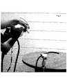
制御ユニットは、内視鏡の上に取り付けられ、得られた組立体(図7)は、内視鏡先端の変位、及び内視鏡の作用通路を通して配置された把持器具の作動を含む機能性についてベンチ試験された。 The control unit was mounted on top of the endoscope and the resulting assembly (FIG. 7) was functional, including displacement of the endoscope tip and operation of a gripping device placed through the action passage of the endoscope. Was bench tested.
ユーザーは、内視鏡シャフト(変位(偏向)が360度で試験された)並びに把持器具(シャフト回転、器具前進及び後進、及び把持器のあご部開閉)の滑らかで苦労のない作動を報告した。 The user reported smooth and effortless operation of the endoscopic shaft (displacement (deflection) tested at 360 degrees) and gripping device (shaft rotation, device forward and backward, and gripper jaw opening and closing). ..
明確にするため別個の実施形態で説明されている本発明の特定の特徴は、単一の実施形態に組み合わせて提供することもできることは分かるであろう。逆に、簡潔にするため、単一の実施形態で説明されている本発明の各種の特徴は、別個にまたは適切なサブコンビネーションで提供することもできる。 It will be appreciated that the particular features of the invention, described in separate embodiments for clarity, can also be provided in combination with a single embodiment. Conversely, for brevity, the various features of the invention described in a single embodiment can also be provided separately or in the appropriate subcombination.
本発明は、その特定の実施形態によって説明してきたが、多くの別法、変更および変形があることは当業者には明らかであることは明白である。従って、本発明は、本願の請求項の精神と広い範囲の中に入るこのような別法、変更および変形すべてを包含することを意図される。本明細書中で言及した刊行物、特許および特許願はすべて、個々の刊行物、特許または特許願の各々があたかも具体的にかつ個々に引用提示されているのと同程度に、それらの全体を本明細書に援用するものである。さらに、本願で引用または確認したことは、本発明の先行技術として利用できるという自白とみなすべきではない。 Although the present invention has been described by its particular embodiment, it will be apparent to those skilled in the art that there are many alternatives, modifications and variations. Accordingly, the present invention is intended to embrace all such alternatives, modifications and modifications that fall within the spirit and broad scope of the claims of the present application. All publications, patents and patent applications referred to herein are as whole as individual publications, patents or patent applications, as if each were specifically and individually cited and presented. Is incorporated herein by reference. Furthermore, what is cited or confirmed in this application should not be regarded as a confession that it can be used as the prior art of the present invention.
Claims (11)
Translated fromJapanese(a)制御ユニットのハウジングに取り付けられたピボット支持体上に取り付けられかつ手の掌によって係合可能な第一インターフェースと、前記第一インターフェースに旋回可能に取り付けられかつ前記手の一つ以上の指によって係合可能な第二インターフェースとを含むユーザーインターフェース;及び
(b)前記ユーザーインターフェースを介して操作可能な駆動ユニットであって、前記駆動ユニットが、二つの手動操作可能な外部つまみを係合し、それによってユーザーが前記手の掌を介して内視鏡のシャフトの変位を制御することができる第一駆動機構と、内視鏡の作用通路を通して配置可能な手術器具の手動操作可能な端を係合するための第二駆動機構とを含み、前記第二インターフェースが、前記第二駆動機構を通して前記手術器具を操作するためのものである。A control unit that can be attached to an endoscope and has a shaft that is displaceable via twomanually operableexternal knobs, including:
(A) A first interface mounted on a pivot support mounted on the housing of the control unit and engageable by the palm of thehand, and one or more swivelably mounted to the first interface of the hand. A user interface including a second interface that can be engaged by a finger ; and (b) a drive unit that can be operated through the user interface,wherein the drive unit engages twomanually operableexternal knobs. And a first drive mechanism that allows the user to control the displacement of the endoscope shaft throughthe palmof the hand and the manually operable end of the surgical instrument that can be placed through the action path of the endoscope. The second interface is for operating the surgical instrument through the second drive mechanism, including a second drive mechanism for engaging .
Applications Claiming Priority (3)
| Application Number | Priority Date | Filing Date | Title |
|---|---|---|---|
| US201562203421P | 2015-08-11 | 2015-08-11 | |
| US62/203,421 | 2015-08-11 | ||
| PCT/IL2016/050879WO2017025969A1 (en) | 2015-08-11 | 2016-08-11 | Control unit for a flexible endoscope |
Publications (3)
| Publication Number | Publication Date |
|---|---|
| JP2018526042A JP2018526042A (en) | 2018-09-13 |
| JP2018526042A5 JP2018526042A5 (en) | 2019-07-18 |
| JP6845809B2true JP6845809B2 (en) | 2021-03-24 |
Family
ID=57983566
Family Applications (1)
| Application Number | Title | Priority Date | Filing Date |
|---|---|---|---|
| JP2017560595AActiveJP6845809B2 (en) | 2015-08-11 | 2016-08-11 | Control unit for flexible endoscopes |
Country Status (13)
| Country | Link |
|---|---|
| US (1) | US10835108B2 (en) |
| EP (1) | EP3334323B1 (en) |
| JP (1) | JP6845809B2 (en) |
| KR (1) | KR102562929B1 (en) |
| CN (1) | CN107847105B (en) |
| AU (1) | AU2016306164A1 (en) |
| BR (1) | BR112017026204A2 (en) |
| CA (1) | CA2984729C (en) |
| DK (1) | DK3334323T3 (en) |
| ES (1) | ES2821101T3 (en) |
| IL (1) | IL255861A (en) |
| MX (1) | MX2017014628A (en) |
| WO (1) | WO2017025969A1 (en) |
Families Citing this family (11)
| Publication number | Priority date | Publication date | Assignee | Title |
|---|---|---|---|---|
| CN107847105B (en) | 2015-08-11 | 2021-01-26 | 人类扩展有限公司 | Control unit for flexible endoscope |
| IT201800004478A1 (en)* | 2018-04-13 | 2019-10-13 | CONTROL SYSTEM FOR MEDICAL DEVICE THAT CAN BE USED IN THE CONTEXT OF AN ENDOSCOPE. | |
| EP3793458B8 (en) | 2018-05-18 | 2024-09-25 | Vascular Technology, Incorporated | Articulating microsurgical instrument |
| WO2020049718A1 (en)* | 2018-09-07 | 2020-03-12 | オリンパス株式会社 | Manipulator system |
| JP7093854B2 (en)* | 2019-01-07 | 2022-06-30 | オリンパス株式会社 | Endoscope |
| DE102019201277A1 (en) | 2019-01-31 | 2020-08-06 | Deutsches Zentrum für Luft- und Raumfahrt e.V. | Device for guiding a medical flexible shaft |
| KR102793231B1 (en)* | 2019-11-18 | 2025-04-07 | 한국전기연구원 | Autonomous endoscope system |
| FR3103696B1 (en)* | 2019-12-03 | 2024-12-20 | Institut Hospitalo Univ De Chirurgie Mini Invasive Guidee Par Limage | Motorized actuation module of an endoscopic instrument |
| CN115334952A (en)* | 2020-02-26 | 2022-11-11 | 人类拓展有限公司 | Control system for colonoscope |
| WO2022072327A1 (en)* | 2020-09-29 | 2022-04-07 | Boston Scientific Scimed, Inc. | Medical device controller |
| WO2024182350A1 (en)* | 2023-02-28 | 2024-09-06 | Boston Scientific Scimed, Inc. | Medical systems, devices, and related methods for rotatably or pivotably coupling medical devices |
Family Cites Families (38)
| Publication number | Priority date | Publication date | Assignee | Title |
|---|---|---|---|---|
| JPS53873A (en)* | 1976-06-23 | 1978-01-07 | Mitsubishi Electric Corp | Fluid blowwout breaker |
| GB2070715A (en)* | 1980-02-14 | 1981-09-09 | Welch Allyn Inc | Endoscope |
| JPH0255907A (en) | 1988-08-20 | 1990-02-26 | Juki Corp | shape recognition device |
| JPH0642644Y2 (en)* | 1988-10-15 | 1994-11-09 | オリンパス光学工業株式会社 | Endoscopic bending device |
| JP3222190B2 (en)* | 1992-04-28 | 2001-10-22 | オリンパス光学工業株式会社 | Bending control device for endoscope |
| JPH1132977A (en)* | 1997-07-17 | 1999-02-09 | Olympus Optical Co Ltd | Endoscope system |
| US20020171625A1 (en) | 2001-05-15 | 2002-11-21 | Jona Group, Ltd. | Pistol-grip trackball mouse |
| JP2003010112A (en)* | 2001-06-28 | 2003-01-14 | Olympus Optical Co Ltd | Endoscope system |
| US20040059191A1 (en)* | 2002-06-17 | 2004-03-25 | Robert Krupa | Mechanical steering mechanism for borescopes, endoscopes, catheters, guide tubes, and working tools |
| JP4615906B2 (en)* | 2004-06-17 | 2011-01-19 | オリンパス株式会社 | Endoscope and endoscope bending operation auxiliary member |
| JP4350755B2 (en)* | 2004-12-03 | 2009-10-21 | オリンパス株式会社 | Detachable electric bending endoscope |
| CN100577085C (en) | 2004-12-03 | 2010-01-06 | 奥林巴斯株式会社 | Insertion part detachable electric curved endoscope |
| US7618413B2 (en) | 2005-06-22 | 2009-11-17 | Boston Scientific Scimed, Inc. | Medical device control system |
| JP4728075B2 (en) | 2005-09-28 | 2011-07-20 | オリンパスメディカルシステムズ株式会社 | Endoscope system |
| EP2247229B1 (en)* | 2008-02-07 | 2016-02-03 | The Trustees Of Columbia University In The City Of New York | Remote endoscope handle manipulation |
| US8419623B2 (en)* | 2009-01-28 | 2013-04-16 | Cani Optical Systems, Llc | Portable endoscope for diverse medical disciplines |
| JP5500844B2 (en)* | 2009-03-18 | 2014-05-21 | 富士フイルム株式会社 | Endoscope |
| FR2948594B1 (en)* | 2009-07-31 | 2012-07-20 | Dexterite Surgical | ERGONOMIC AND SEMI-AUTOMATIC MANIPULATOR AND INSTRUMENT APPLICATIONS FOR MINI-INVASIVE SURGERY |
| US8543240B2 (en)* | 2009-11-13 | 2013-09-24 | Intuitive Surgical Operations, Inc. | Master finger tracking device and method of use in a minimally invasive surgical system |
| EP2617344B1 (en) | 2011-02-28 | 2016-12-07 | Olympus Corporation | Bending portion-equipped medical apparatus |
| WO2012127462A1 (en)* | 2011-03-22 | 2012-09-27 | Human Extensions Ltd. | Motorized surgical instruments |
| US9901412B2 (en)* | 2011-04-29 | 2018-02-27 | Vanderbilt University | Dexterous surgical manipulator and method of use |
| JP5395282B2 (en) | 2011-06-16 | 2014-01-22 | オリンパスメディカルシステムズ株式会社 | Endoscope |
| JP5330627B2 (en)* | 2011-09-08 | 2013-10-30 | オリンパスメディカルシステムズ株式会社 | Multi-DOF forceps |
| EP2819609B1 (en)* | 2012-02-29 | 2020-10-21 | TransEnterix Europe Sàrl | Manual control system for maneuvering an endoscope |
| US20140275763A1 (en)* | 2013-03-15 | 2014-09-18 | Lucent Medical Systems, Inc. | Partially disposable endoscopic device |
| US9949623B2 (en)* | 2013-05-17 | 2018-04-24 | Endochoice, Inc. | Endoscope control unit with braking system |
| US20160271385A1 (en)* | 2013-07-11 | 2016-09-22 | Transenterix Surgical, Inc. | Surgical instruments, systems, and methods for coupling of electrical energy to surgical instruments |
| ES2715393T3 (en)* | 2013-09-01 | 2019-06-04 | Human Extensions Ltd | Control unit for a medical device |
| WO2015038290A1 (en)* | 2013-09-12 | 2015-03-19 | Endocon, Inc. | Power-assisted medical scope |
| WO2015077584A2 (en)* | 2013-11-22 | 2015-05-28 | Massachusetts Institute Of Technology | Steering techniques for surgical instruments |
| JP6006455B2 (en)* | 2014-06-20 | 2016-10-12 | オリンパス株式会社 | Endoscope device |
| JP6110828B2 (en)* | 2014-09-30 | 2017-04-05 | 富士フイルム株式会社 | Endoscope device |
| WO2016092981A1 (en)* | 2014-12-10 | 2016-06-16 | オリンパス株式会社 | Endoscope system |
| WO2016099614A1 (en)* | 2014-12-15 | 2016-06-23 | Gyrus Acmi, Inc. (D/B/A/ Olympus Surgical Technologies America) | Improved control of a basket retrieval device |
| CN107072481B (en)* | 2015-03-18 | 2018-12-18 | 奥林巴斯株式会社 | Bend operating apparatus and endoscope |
| JP6116777B1 (en)* | 2015-06-08 | 2017-04-19 | オリンパス株式会社 | Bending operation device and endoscope |
| CN107847105B (en) | 2015-08-11 | 2021-01-26 | 人类扩展有限公司 | Control unit for flexible endoscope |
- 2016
- 2016-08-11CNCN201680029036.XApatent/CN107847105B/enactiveActive
- 2016-08-11WOPCT/IL2016/050879patent/WO2017025969A1/ennot_activeCeased
- 2016-08-11USUS15/565,177patent/US10835108B2/enactiveActive
- 2016-08-11BRBR112017026204-5Apatent/BR112017026204A2/ennot_activeApplication Discontinuation
- 2016-08-11CACA2984729Apatent/CA2984729C/enactiveActive
- 2016-08-11ESES16834773Tpatent/ES2821101T3/enactiveActive
- 2016-08-11KRKR1020177035356Apatent/KR102562929B1/enactiveActive
- 2016-08-11DKDK16834773.0Tpatent/DK3334323T3/enactive
- 2016-08-11MXMX2017014628Apatent/MX2017014628A/enunknown
- 2016-08-11AUAU2016306164Apatent/AU2016306164A1/ennot_activeAbandoned
- 2016-08-11EPEP16834773.0Apatent/EP3334323B1/enactiveActive
- 2016-08-11JPJP2017560595Apatent/JP6845809B2/enactiveActive
- 2017
- 2017-11-22ILIL255861Apatent/IL255861A/enunknown
Also Published As
| Publication number | Publication date |
|---|---|
| AU2016306164A1 (en) | 2017-11-30 |
| EP3334323A4 (en) | 2019-05-15 |
| CN107847105A (en) | 2018-03-27 |
| MX2017014628A (en) | 2018-06-06 |
| KR20180038417A (en) | 2018-04-16 |
| CN107847105B (en) | 2021-01-26 |
| CA2984729A1 (en) | 2017-02-16 |
| EP3334323B1 (en) | 2020-06-24 |
| KR102562929B1 (en) | 2023-08-03 |
| CA2984729C (en) | 2024-02-27 |
| JP2018526042A (en) | 2018-09-13 |
| US20180098687A1 (en) | 2018-04-12 |
| US10835108B2 (en) | 2020-11-17 |
| BR112017026204A2 (en) | 2018-09-04 |
| WO2017025969A1 (en) | 2017-02-16 |
| IL255861A (en) | 2018-01-31 |
| ES2821101T3 (en) | 2021-04-23 |
| EP3334323A1 (en) | 2018-06-20 |
| DK3334323T3 (en) | 2020-09-28 |
Similar Documents
| Publication | Publication Date | Title |
|---|---|---|
| JP6845809B2 (en) | Control unit for flexible endoscopes | |
| US11020197B2 (en) | Control unit for a medical device | |
| US12295604B2 (en) | Control unit for a medical device | |
| WO2022253065A1 (en) | Portable manual surgical robot | |
| US12433474B2 (en) | Control system for a colonoscope | |
| HK1253926B (en) | Control unit attachable to an endoscope having a shaft deflectable via two rotatable knobs to allow one-handed operation of the knobs | |
| HK1253926A1 (en) | Control unit attachable to an endoscope having a shaft deflectable via two rotatable knobs to allow one-handed operation of the knobs | |
| HK40008022B (en) | Control unit for a medical device | |
| HK40008022A (en) | Control unit for a medical device | |
| HK1224538B (en) | Control unit for a medical device |
Legal Events
| Date | Code | Title | Description |
|---|---|---|---|
| A521 | Request for written amendment filed | Free format text:JAPANESE INTERMEDIATE CODE: A821 Effective date:20171117 | |
| A521 | Request for written amendment filed | Free format text:JAPANESE INTERMEDIATE CODE: A523 Effective date:20190612 | |
| A621 | Written request for application examination | Free format text:JAPANESE INTERMEDIATE CODE: A621 Effective date:20190612 | |
| A977 | Report on retrieval | Free format text:JAPANESE INTERMEDIATE CODE: A971007 Effective date:20200722 | |
| A131 | Notification of reasons for refusal | Free format text:JAPANESE INTERMEDIATE CODE: A131 Effective date:20200804 | |
| A521 | Request for written amendment filed | Free format text:JAPANESE INTERMEDIATE CODE: A523 Effective date:20201026 | |
| TRDD | Decision of grant or rejection written | ||
| A01 | Written decision to grant a patent or to grant a registration (utility model) | Free format text:JAPANESE INTERMEDIATE CODE: A01 Effective date:20210205 | |
| A61 | First payment of annual fees (during grant procedure) | Free format text:JAPANESE INTERMEDIATE CODE: A61 Effective date:20210226 | |
| R150 | Certificate of patent or registration of utility model | Ref document number:6845809 Country of ref document:JP Free format text:JAPANESE INTERMEDIATE CODE: R150 | |
| R250 | Receipt of annual fees | Free format text:JAPANESE INTERMEDIATE CODE: R250 | |
| R250 | Receipt of annual fees | Free format text:JAPANESE INTERMEDIATE CODE: R250 | |
| S533 | Written request for registration of change of name | Free format text:JAPANESE INTERMEDIATE CODE: R313533 | |
| S111 | Request for change of ownership or part of ownership | Free format text:JAPANESE INTERMEDIATE CODE: R313113 |