Movatterモバイル変換


[0]ホーム

URL:


JP6845603B2 - Program, device control method and terminal control method - Google Patents

Program, device control method and terminal control method
Download PDF

Info

Publication number
JP6845603B2
JP6845603B2JP2019220054AJP2019220054AJP6845603B2JP 6845603 B2JP6845603 B2JP 6845603B2JP 2019220054 AJP2019220054 AJP 2019220054AJP 2019220054 AJP2019220054 AJP 2019220054AJP 6845603 B2JP6845603 B2JP 6845603B2
Authority
JP
Japan
Prior art keywords
information
vehicle
mobile terminal
vehicle device
operating condition
Prior art date
Legal status (The legal status is an assumption and is not a legal conclusion. Google has not performed a legal analysis and makes no representation as to the accuracy of the status listed.)
Active
Application number
JP2019220054A
Other languages
Japanese (ja)
Other versions
JP2020053987A (en
Inventor
高木 大輔
大輔 高木
Current Assignee (The listed assignees may be inaccurate. Google has not performed a legal analysis and makes no representation or warranty as to the accuracy of the list.)
Micware Co Ltd
Original Assignee
Micware Co Ltd
Priority date (The priority date is an assumption and is not a legal conclusion. Google has not performed a legal analysis and makes no representation as to the accuracy of the date listed.)
Filing date
Publication date
Application filed by Micware Co LtdfiledCriticalMicware Co Ltd
Priority to JP2019220054ApriorityCriticalpatent/JP6845603B2/en
Publication of JP2020053987ApublicationCriticalpatent/JP2020053987A/en
Application grantedgrantedCritical
Publication of JP6845603B2publicationCriticalpatent/JP6845603B2/en
Activelegal-statusCriticalCurrent
Anticipated expirationlegal-statusCritical

Links

Images

Landscapes

Description

Translated fromJapanese

本発明は、車両に搭載される車載装置と、携帯端末とで情報を連携させる情報連携システムに用いられるプログラム、装置制御方法及び端末制御方法に関する。 The present invention relates to a program, a device control method, and a terminal control method used in an information cooperation system for linking information between an in-vehicle device mounted on a vehicle and a mobile terminal.

従来、車両に搭載される車載装置と、携帯端末とを無線通信させて、無線通信が確立された携帯端末から画像や音声などの情報を車載装置に提供することが行われている。
この種の情報連携システムとしては、車載装置が無線通信の可能な所定の距離に位置する携帯端末を検知した場合、検知した携帯端末からデータを取得する無線通信システムが知られている(特許文献1参照)。
Conventionally, it has been practiced to wirelessly communicate between an in-vehicle device mounted on a vehicle and a mobile terminal to provide information such as images and sounds to the in-vehicle device from the mobile terminal for which wireless communication has been established.
As an information linkage system of this type, there is known a wireless communication system that acquires data from a detected mobile terminal when an in-vehicle device detects a mobile terminal located at a predetermined distance capable of wireless communication (Patent Documents). 1).

特許文献1の無線通信システムでは、車載装置が無線通信可能な領域に携帯端末が侵入した場合、車載装置の無線確立部が検知した携帯端末に対して近距離通信を用いてペアリング処理を実施し、携帯端末との間に無線通信を確立している。特許文献1の無線通信システムは、接続相手の特定および認証、通信に用いる共通の暗号化設定などを双方の装置で行うペアリング処理を無線確立部が行うことで、ユーザのスキルに関係なく、携帯端末装置と、車載装置とを簡単に連携制御させることができる、としている。 In the wireless communication system ofPatent Document 1, when a mobile terminal invades an area where an in-vehicle device can perform wireless communication, a pairing process is performed on the mobile terminal detected by the wireless establishment unit of the in-vehicle device using short-range communication. However, wireless communication has been established with mobile terminals. In the wireless communication system ofPatent Document 1, the wireless establishment unit performs the pairing process in which both devices perform the identification and authentication of the connection partner, the common encryption setting used for communication, and the like, regardless of the skill of the user. According to the company, the mobile terminal device and the in-vehicle device can be easily linked and controlled.

特開2010−130669号公報JP-A-2010-130669

ところで、情報連携システムでは、より簡単な構成で車載装置と携帯端末とを連携させることが求められており、近距離通信を用いたペアリング処理を実施する無線確立部が必要な特許文献1の構成では十分ではなく、更なる改良が求められている。 By the way, in an information cooperation system, it is required to link an in-vehicle device and a mobile terminal with a simpler configuration, andPatent Document 1 requires a wireless establishment unit that performs pairing processing using short-range communication. The configuration is not sufficient and further improvements are needed.

そこで、本発明は上記事由に鑑みて為されたものであり、より簡単な構成で車載装置と携帯端末とを連携させる情報連携システムに用いられるプログラム、装置制御方法及び端末制御方法を提供することを目的とする。 Therefore, the present invention has been made in view of the above reasons, and provides a program, a device control method, and a terminal control method used in an information cooperation system for linking an in-vehicle device and a mobile terminal with a simpler configuration. With the goal.

上記の目的を達成するため、本開示にかかる情報連携システムは、車載装置と、携帯端末と、を備える。上記車載装置は、車両に搭載される。上記車載装置は、第1の発信機と、第1の受信機と、稼働設定部と、を有する。上記第1の発信機は、第1の無線データを発信する。上記第1の受信機は、第2の無線データを受信する。上記稼働設定部は、上記車載装置の稼働条件を設定する。上記携帯端末は、第2の受信機と、第2の発信機と、判定部と、を有する。上記第2の受信機は、上記第1の無線データを受信する。上記第2の発信機は、上記第2の無線データを発信する。上記判定部は、上記第1の無線データを受信した受信信号強度と、上記第1の無線データの発信信号強度とから上記車載装置との距離を判定する。上記第1の無線データは、上記発信信号強度の情報を含んでいる。上記第2の無線データは、上記稼働条件を指示する稼働条件指示情報を含んでいる。上記携帯端末は、上記判定部が上記車載装置との距離を所定の値又は当該所定の値未満と判定した場合、上記第2の発信機が上記第2の無線データを発信する。上記車載装置は、上記稼働設定部が上記稼働条件指示情報に基づいて上記稼働条件を設定する。 In order to achieve the above object, the information cooperation system according to the present disclosure includes an in-vehicle device and a mobile terminal. The in-vehicle device is mounted on a vehicle. The in-vehicle device includes a first transmitter, a first receiver, and an operation setting unit. The first transmitter transmits the first wireless data. The first receiver receives the second radio data. The operation setting unit sets the operation conditions of the in-vehicle device. The mobile terminal has a second receiver, a second transmitter, and a determination unit. The second receiver receives the first radio data. The second transmitter transmits the second radio data. The determination unit determines the distance to the in-vehicle device from the received signal strength of receiving the first wireless data and the transmission signal strength of the first wireless data. The first radio data includes information on the transmitted signal strength. The second radio data includes operating condition instruction information for instructing the operating conditions. In the mobile terminal, when the determination unit determines that the distance from the in-vehicle device is a predetermined value or less than the predetermined value, the second transmitter transmits the second radio data. In the in-vehicle device, the operation setting unit sets the operation conditions based on the operation condition instruction information.

本開示によれば、車載装置と携帯端末との距離が所定の値又は当該所定の値未満となった状態で、携帯端末から稼働条件指示情報が車載装置に発信され、車載装置において稼働条件が設定される。つまり、近距離通信を用いたペアリング処理を実施することなく、距離の判定を利用して車載装置と携帯端末とを連携させることができる。 According to the present disclosure, when the distance between the in-vehicle device and the mobile terminal is a predetermined value or less than the predetermined value, the operating condition instruction information is transmitted from the mobile terminal to the in-vehicle device, and the operating conditions in the in-vehicle device are set. Set. That is, the in-vehicle device and the mobile terminal can be linked by using the distance determination without performing the pairing process using the short-range communication.

上述の構成において、上記車両の車内には、上記第1の発信機と上記第1の受信機とが対として複数配置されてもよい。 In the above configuration, a plurality of the first transmitter and the first receiver may be arranged as a pair in the vehicle.

上述の構成において、上記携帯端末は、上記第2の発信機が所定のデータ量、若しくは所定のデータ量未満の第2の無線データを発信してもよい。 In the above configuration, in the mobile terminal, the second transmitter may transmit a predetermined amount of data or a second wireless data less than a predetermined amount of data.

上述の構成において、上記車載装置は、現在位置取得部と、経路探索部とをさらに有していてもよい。上記現在位置取得部は、現在位置を取得する。上記経路探索部は、上記現在位置から目的地までの経路を探索する。上記携帯端末は、位置情報取得部をさらに有していてもよい。上記位置情報取得部は、位置情報を取得する。上記第2の無線データは、上記位置情報取得部にて取得された位置情報を含んでいてもよい。上記車載装置の上記経路探索部は、上記現在位置取得部が取得した現在位置と、上記携帯端末の位置情報取得部が取得した位置情報とが所定の範囲内にある場合に、現在位置から目的地までの経路を探索する、ようにしてもよい。 In the above configuration, the vehicle-mounted device may further include a current position acquisition unit and a route search unit. The current position acquisition unit acquires the current position. The route search unit searches for a route from the current position to the destination. The mobile terminal may further have a position information acquisition unit. The position information acquisition unit acquires the position information. The second radio data may include the position information acquired by the position information acquisition unit. The route search unit of the in-vehicle device is intended from the current position when the current position acquired by the current position acquisition unit and the position information acquired by the position information acquisition unit of the mobile terminal are within a predetermined range. You may search for a route to the ground.

本開示にかかる情報連携システムによれば、より簡単な構成で車載装置と携帯端末とを連携させることができる。 According to the information linkage system according to the present disclosure, the in-vehicle device and the mobile terminal can be linked with a simpler configuration.

実施形態にかかる情報連携システムの概略構成ブロック図である。It is a schematic block diagram of the information linkage system which concerns on embodiment.実施形態にかかる車載装置及び携帯端末を示す図である。It is a figure which shows the in-vehicle device and the mobile terminal which concerns on embodiment.実施形態にかかる情報連携システムにおいて実行される処理動作の手順を示すシーケンスである。It is a sequence which shows the procedure of the processing operation executed in the information linkage system which concerns on embodiment.稼働条件指示情報を入力する際に携帯端末に表示される画面の例を示す図である。It is a figure which shows the example of the screen which is displayed on the mobile terminal when inputting the operation condition instruction information.携帯端末を車載通信機に近づけることを促すアテンションを表示する携帯端末の画面の例を示す図である。It is a figure which shows the example of the screen of the mobile terminal which displays the attention which urges the mobile terminal to come close to an in-vehicle communication device.第2の無線データを送信中である旨のアテンションを表示する携帯端末の画面の例を示す図である。It is a figure which shows the example of the screen of the mobile terminal which displays the attention to the effect that the second wireless data is being transmitted.第2の無線データの送信完了のアテンションを表示する携帯端末の画面の例を示す図である。It is a figure which shows the example of the screen of the mobile terminal which displays the attention of the completion of transmission of the second wireless data.稼働条件指示情報を受信した旨のアテンションを表示する車載装置の画面の例を示す図である。It is a figure which shows the example of the screen of the in-vehicle device which displays the attention that the operation condition instruction information was received.稼働条件が設定された車載装置の画面の例を示す図である。It is a figure which shows the example of the screen of the in-vehicle device which set the operating condition.

以下、本発明の実施の形態に係る情報連携システム1について、図面を参照しつつ説明する。 Hereinafter, theinformation linkage system 1 according to the embodiment of the present invention will be described with reference to the drawings.

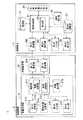
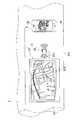
本実施の形態にかかる情報連携システム1は、図1及び図2に示すように、車載装置2と、携帯端末3と、を備えている。本実施の形態においては、車載装置2は、図2に示すように、車両10に搭載される。図1では、信号の流れを実線の矢印、若しくは実線の両矢印で例示している。また、図1では、破線の矢印で無線信号の流れを例示している。 As shown in FIGS. 1 and 2, theinformation cooperation system 1 according to the present embodiment includes an in-vehicle device 2 and amobile terminal 3. In the present embodiment, the in-vehicle device 2 is mounted on thevehicle 10 as shown in FIG. In FIG. 1, the signal flow is illustrated by a solid arrow or a solid double-headed arrow. Further, in FIG. 1, the flow of the radio signal is illustrated by the broken line arrow.

車載装置2は、車載本体部21と、車載通信機22とを備えている。 The in-vehicle device 2 includes an in-vehiclemain body 21 and an in-vehicle communication device 22.

車載本体部21は、制御部211と、第1の記憶部213と、現在位置取得部214と、車載表示部215と、第1の入力部216と、第1の出力部217とを備えている。車載本体部21は、例えば、出発地から目的地までの経路探索及び案内を行うナビゲーション機能、音楽を再生するオーディオ機能、若しくは動画を再生する動画再生機能の少なくとも一つを有するように構成されている。本実施の形態においては、車載本体部21がナビゲーション機能を有する例で説明する。 The vehicle-mountedmain unit 21 includes a control unit 211, afirst storage unit 213, a currentposition acquisition unit 214, an vehicle-mounteddisplay unit 215, afirst input unit 216, and afirst output unit 217. There is. The vehicle-mountedmain unit 21 is configured to have at least one of, for example, a navigation function for searching and guiding a route from a departure point to a destination, an audio function for playing music, or a moving image playing function for playing a moving image. There is. In this embodiment, an example will be described in which the vehicle-mountedmain body 21 has a navigation function.

制御部211は、経路探索部212と、稼働設定部218とを有している。経路探索部212は、現在位置取得部214で取得される現在位置から目的地までの経路を探索する。経路探索部212は、探索により得られた経路を車載表示部215に表示させる。稼働設定部218は、車載装置2の稼働条件を設定する。本実施の形態では、車載装置2の稼働条件には、ユーザが指定する稼働条件が含まれる。車載装置2の稼働条件としては、車載表示部215においてユーザ好みの表示を実行するための画面設定情報が挙げられる。なお、例えば、車載本体部21がオーディオ機能を有している場合、車載装置2の稼働条件としては、再生する曲の情報が挙げられる。例えば、車載本体部21が動画再生機能を有している場合、車載装置2の稼働条件としては、再生する動画の情報が挙げられる。制御部211は、CPU(Central Processing Unit)を用いて構成される。 The control unit 211 has a route search unit 212 and an operation setting unit 218. The route search unit 212 searches for a route from the current position acquired by the currentposition acquisition unit 214 to the destination. The route search unit 212 causes the vehicle-mounteddisplay unit 215 to display the route obtained by the search. The operation setting unit 218 sets the operation conditions of the in-vehicle device 2. In the present embodiment, the operating conditions of the in-vehicle device 2 include operating conditions specified by the user. Examples of the operating condition of the in-vehicle device 2 include screen setting information for executing the user's favorite display on the in-vehicle display unit 215. For example, when the vehicle-mountedmain unit 21 has an audio function, the operating condition of the vehicle-mounteddevice 2 includes information on a song to be reproduced. For example, when the in-vehiclemain body 21 has a moving image reproduction function, the operating condition of the in-vehicle device 2 includes information on the moving image to be reproduced. The control unit 211 is configured by using a CPU (Central Processing Unit).

第1の記憶部213は、例えば、ユーザプロファイルに応じた画面の設定を行うために必要なプログラム、ナビゲーション機能に必要なプログラム、その他各種情報を記憶するストレージである。第1の記憶部213は、携帯端末3から送られてきた稼働条件指示情報を記憶することができるように構成されている。本実施の形態では、第1の記憶部213は、ユーザプロファイルに応じた画面の設定を行うため、ユーザプロファイルと、画面設定情報との対応情報が記憶されている。第1の記憶部213は、例えば、不揮発性メモリで構成される。不揮発性メモリとしては、例えば、SSD(Solid State Drive)が挙げられる。 Thefirst storage unit 213 is, for example, a storage for storing a program necessary for setting a screen according to a user profile, a program necessary for a navigation function, and various other information. Thefirst storage unit 213 is configured to be able to store the operating condition instruction information sent from themobile terminal 3. In the present embodiment, since thefirst storage unit 213 sets the screen according to the user profile, the correspondence information between the user profile and the screen setting information is stored. Thefirst storage unit 213 is composed of, for example, a non-volatile memory. Examples of the non-volatile memory include SSD (Solid State Drive).

現在位置取得部214は、車両10に搭載された車載装置2の現在位置を取得する。現在位置取得部214は、例えば、GPS(Global Positioning System)センサで構成される。現在位置取得部214は、GPSセンサに加え、ジャイロセンサ及び加速度センサを用いて構成されてもよい。 The currentposition acquisition unit 214 acquires the current position of the in-vehicle device 2 mounted on thevehicle 10. The currentposition acquisition unit 214 is composed of, for example, a GPS (Global Positioning System) sensor. The currentposition acquisition unit 214 may be configured by using a gyro sensor and an acceleration sensor in addition to the GPS sensor.

車載表示部215は、例えば、車載装置2を使用する際に必要な操作情報、地図情報、若しくはPOI(Point Of Interest)情報を表示することができるように構成されている。車載表示部215として、例えば、液晶表示装置、若しくは有機EL(Electro Luminescence)表示装置が利用できる。車載表示部215には、表示機能に加え、入力機能を備えたタッチパネルが採用されてもよい。車載表示部215は、タッチパネルの代わりに、入力機能を持たない単なる表示装置でもよい。 The vehicle-mounteddisplay unit 215 is configured to be able to display, for example, operation information, map information, or POI (Point Of Interest) information required when using the vehicle-mounteddevice 2. As the in-vehicle display unit 215, for example, a liquid crystal display device or an organic EL (Electroluminescence) display device can be used. The in-vehicle display unit 215 may employ a touch panel having an input function in addition to the display function. The vehicle-mounteddisplay unit 215 may be a simple display device having no input function instead of the touch panel.

第1の入力部216は、ユーザが車載装置2に対して各種情報を入力するために使用される。車載表示部215にタッチパネルが採用されている場合には、タッチパネルが第1の入力部216を兼ねてもよい。第1の入力部216として、タッチパネルの代わりに、入力専用の入力装置を採用してもよい。入力装置による情報の入力形態として、例えば、音声入力、物理キーによる入力、外部入力機器による入力が挙げられる。 Thefirst input unit 216 is used by the user to input various information to the in-vehicle device 2. When a touch panel is adopted for the vehicle-mounteddisplay unit 215, the touch panel may also serve as thefirst input unit 216. As thefirst input unit 216, an input device dedicated to input may be adopted instead of the touch panel. Examples of the input form of information by the input device include voice input, physical key input, and external input device input.

第1の出力部217は、制御部211によって処理された出力情報を出力する。第1の出力部217による出力形態としては、例えば、音声出力、外部出力機器による外部出力が挙げられる。 Thefirst output unit 217 outputs the output information processed by the control unit 211. Examples of the output form by thefirst output unit 217 include audio output and external output by an external output device.

車載通信機22は、第1の発信機221と、第1の受信機222と、を備えている。車載通信機22は、例えば、BLE(Bluetooth(登録商標) Low Energy)の通信規格に対応した通信ができるように構成されている。車載通信機22は、携帯端末3との距離が数センチ程度の近接距離において、稼働条件指示情報が無線通信で受信できるように構成されている。車載通信機22と車載本体部21とは、図2に示すように、別筐体で構成されている。車載通信機22と車載本体部21とは、通信線223で相互に情報通信できるように接続されている。図2では、車載通信機22から無線の電波が発信される状態を、複数の円弧で図示している。車載通信機22と車載本体部21とは、通信線223で接続される構成だけに限られない。車載通信機22と車載本体部21とは、無線で情報通信できるように接続されてもよい。また、車載通信機22と車載本体部21とは、同じ筐体内に収容され物理的に一体として構成されてもよい。 The in-vehicle communication device 22 includes afirst transmitter 221 and afirst receiver 222. The in-vehicle communication device 22 is configured to enable communication corresponding to, for example, a communication standard of BLE (Bluetooth (registered trademark) Low Energy). The in-vehicle communication device 22 is configured so that the operating condition instruction information can be received by wireless communication at a short distance of about several centimeters from themobile terminal 3. As shown in FIG. 2, the in-vehicle communication device 22 and the in-vehiclemain body 21 are configured in separate housings. The in-vehicle communication device 22 and the in-vehiclemain body 21 are connected to each other via acommunication line 223 so that information can be communicated with each other. In FIG. 2, a state in which a radio wave is transmitted from the in-vehicle communication device 22 is illustrated by a plurality of arcs. The in-vehicle communication device 22 and the in-vehiclemain body 21 are not limited to a configuration in which they are connected by acommunication line 223. The in-vehicle communication device 22 and the in-vehiclemain body 21 may be connected so that information communication can be performed wirelessly. Further, the in-vehicle communication device 22 and the in-vehiclemain body 21 may be housed in the same housing and physically integrated.

第1の発信機221は、発信信号強度の情報を含んだ第1の無線データを発信する。第1の無線データの発信は、所定の時間間隔で行われる。第1の発信機221は、例えば、第1の無線データが100ミリ秒から700ミリ秒内での一定の時間間隔で発信できるように構成されている。第1の発信機221は、第1の無線データの発信間隔が短くなれば、第1の無線データが受信される可能性が高くなる傾向にある。第1の発信機221は、第1の無線データの発信間隔が短くなれば、消費電力が多くなる傾向にある。 Thefirst transmitter 221 transmits the first radio data including the information of the transmission signal strength. The transmission of the first radio data is performed at predetermined time intervals. Thefirst transmitter 221 is configured so that, for example, the first radio data can be transmitted at regular time intervals within 100 milliseconds to 700 milliseconds. Thefirst transmitter 221 tends to have a higher possibility of receiving the first radio data as the transmission interval of the first radio data becomes shorter. The power consumption of thefirst transmitter 221 tends to increase as the transmission interval of the first wireless data becomes shorter.

第1の受信機222は、携帯端末3から発信される第2の無線データを受信する。第2の無線データには、携帯端末3で設定された稼働条件指示情報が含まれている。第2の無線データのデータ量は、所定のデータ量、若しくは所定のデータ量未満とされることが好ましい。第2の無線データのデータ量は、例えば、128バイト、若しくは128バイト未満とすることができる。第2の無線データのデータ量を抑えることで、第2の無線データを送信する携帯端末3の通信量を抑えることができる。その結果、第2の無線データを送信する携帯端末3の消費電力を抑えることができる。 Thefirst receiver 222 receives the second radio data transmitted from themobile terminal 3. The second wireless data includes the operating condition instruction information set in themobile terminal 3. The data amount of the second radio data is preferably a predetermined amount of data or less than a predetermined amount of data. The data amount of the second radio data can be, for example, 128 bytes or less than 128 bytes. By suppressing the amount of data of the second wireless data, it is possible to suppress the amount of communication of themobile terminal 3 that transmits the second wireless data. As a result, the power consumption of themobile terminal 3 that transmits the second wireless data can be suppressed.

なお、本実施の形態にかかる車載装置2は、1つの車載本体部21と、1つの車載通信機22を有している。車載装置2は、図2に示すように、1つの車載本体部21と1つの車載通信機22とが、センターコンソール101に配置されている。車載装置2は、1つの車載本体部21と、1つの車載通信機22を有する構成だけに限定されない。車両10の車内に、第1の発信機221と第1の受信機222とを対とした車載通信機22が複数配置されてもよい。つまり、車載装置2は、1つの車載本体部21と、複数の車載通信機22と、を備えていてもよい。車載装置2は、例えば、車内の異なる場所に、車載通信機22をそれぞれ配置することができる。具体的には、車内のセンターコンソール101に車載通信機22を配置し、運転席のヘッドレスト裏面側及び助手席のヘッドレスト裏面側に車載通信機22を配置することができる。車内に複数の車載通信機22を配置することで、運転席、助手席、後部座席のいずれの座席にユーザが居ても車載通信機22を利用することができる。 The in-vehicle device 2 according to the present embodiment has one in-vehiclemain body 21 and one in-vehicle communication device 22. In the vehicle-mounteddevice 2, as shown in FIG. 2, one vehicle-mountedmain body 21 and one vehicle-mountedcommunication device 22 are arranged on thecenter console 101. The in-vehicle device 2 is not limited to a configuration having one in-vehiclemain body 21 and one in-vehicle communication device 22. A plurality of in-vehicle communication devices 22 in which thefirst transmitter 221 and thefirst receiver 222 are paired may be arranged in the vehicle of thevehicle 10. That is, the in-vehicle device 2 may include one in-vehiclemain body 21 and a plurality of in-vehicle communication devices 22. In the vehicle-mounteddevice 2, for example, the vehicle-mountedcommunication device 22 can be arranged at different locations in the vehicle. Specifically, the vehicle-mountedcommunication device 22 can be arranged on thecenter console 101 in the vehicle, and the vehicle-mountedcommunication device 22 can be arranged on the back side of the headrest of the driver's seat and the back side of the headrest of the passenger seat. By arranging a plurality of in-vehicle communication devices 22 in the vehicle, the in-vehicle communication device 22 can be used regardless of whether the user is in the driver's seat, the passenger seat, or the rear seat.

携帯端末3は、図1に示すように、携帯制御部31と、第2の記憶部33と、位置情報取得部34と、携帯表示部35と、第2の発信機361と、第2の受信機362と、ネットワーク通信部37と、第2の入力部38と、第2の出力部39とを備えている。本実施の形態において、携帯端末3は、通話機能、地図表示機能及び情報検索機能を有している。携帯端末3の例として、スマートフォン、タブレット端末、ノートパソコン、若しくは携帯電話が挙げられる。本実施の形態では、携帯端末3が通信端末として機能できるように構成されている。通信端末は、移動体通信システムにおける通信ネットワークを介して、インターネットに接続できるように構成されている。通信端末は、インターネットに接続して、各種の情報を収集することができる。 As shown in FIG. 1, themobile terminal 3 includes amobile control unit 31, asecond storage unit 33, a positioninformation acquisition unit 34, amobile display unit 35, a second transmitter 361, and a second. It includes areceiver 362, anetwork communication unit 37, asecond input unit 38, and asecond output unit 39. In the present embodiment, themobile terminal 3 has a call function, a map display function, and an information retrieval function. Examples of themobile terminal 3 include smartphones, tablet terminals, laptop computers, and mobile phones. In this embodiment, themobile terminal 3 is configured to function as a communication terminal. The communication terminal is configured to be able to connect to the Internet via a communication network in a mobile communication system. The communication terminal can connect to the Internet and collect various kinds of information.

携帯端末3の通話機能は、携帯制御部31が第2の記憶部33に記憶された通話プログラムに基づく処理を実行させることにより実現される。携帯端末3の地図表示機能は、携帯制御部31が第2の記憶部33に記憶された地図表示プログラムに基づく処理を実行させることにより実現される。携帯端末3の情報検索機能は、携帯制御部31が第2の記憶部33に記憶された情報検索プログラムに基づく処理を実行させることにより実現される。携帯制御部31は、CPUを用いて構成されている。 The call function of themobile terminal 3 is realized by having themobile control unit 31 execute a process based on the call program stored in thesecond storage unit 33. The map display function of themobile terminal 3 is realized by causing themobile control unit 31 to execute a process based on the map display program stored in thesecond storage unit 33. The information retrieval function of themobile terminal 3 is realized by causing themobile control unit 31 to execute a process based on the information retrieval program stored in thesecond storage unit 33. Themobile control unit 31 is configured by using a CPU.

携帯制御部31は、第2の記憶部33に記憶された判定プログラムに基づく処理を実行させることにより、判定部32として機能する。 Themobile control unit 31 functions as thedetermination unit 32 by causing thesecond storage unit 33 to execute a process based on the determination program stored in thesecond storage unit 33.

判定部32は、車載装置2側から送信された第1の無線データを携帯端末3で受信したときの受信信号強度の情報と、第1の無線データに含まれる発信信号強度の情報とから、携帯端末3と車載装置2との距離を判定する。判定部32は、距離と電波強度との関係を示す計算式、若しくは距離と電波強度との関係を示すデータテーブルに基づいて、携帯端末3と車載装置2との距離を算出している。計算式やデータテーブルは、予め第2の記憶部33に記憶されていればよい。すなわち、判定部32は、第2の受信機362で第1の無線信号を受信した信号強度から当該距離を判定することができるように構成されている。判定部32が携帯端末3と車載装置2との距離を所定の値D又は該所定の値D未満と判定した場合、携帯制御部31は、第2の発信機361を介して稼働条件指示情報を含んだ第2の無線データを発信する。本実施の形態において、判定部32は、無線通信により無線データの転送を半径数十メートル程度に渡って行うことを許容する構成ではなく、携帯端末3が車載通信機22にかざされた状態を判別できるように構成されている。言い換えれば、判定部32は、携帯端末3と車載装置2との距離が数センチ程度の距離を判定できるように構成されている。本実施の形態の情報連携システム1においては、ユーザが携帯端末3を車載通信機22にかざすように配置させることで、直感的に稼働条件指示情報を携帯端末3から車載装置2へ転送させることができる。なお、第2の無線データには、稼働条件指示情報に加え、車載装置2において稼働条件指示情報に応じた各種のアプリケーション機能を開始させることができるように、制御部211を機能させるトリガー情報を含んでいてもよい。本実施の形態では、稼働条件指示情報として、携帯端末3のユーザ識別情報であるユーザプロファイルを用いる。情報連携システム1は、携帯端末3のユーザ識別情報に応じて、ユーザプロファイルごとに車載装置2の画面設定を変更できるように構成されている。言い換えれば、ユーザが車載装置2に稼働条件を直接設定することなく、ユーザの携帯端末3にある稼働条件指示情報を車載装置2に送信して車載装置2が自動的に稼働条件を設定することができる。 Thedetermination unit 32 is based on information on the received signal strength when themobile terminal 3 receives the first wireless data transmitted from the vehicle-mounteddevice 2 side and information on the transmitted signal strength included in the first wireless data. The distance between themobile terminal 3 and the in-vehicle device 2 is determined. Thedetermination unit 32 calculates the distance between themobile terminal 3 and the in-vehicle device 2 based on a calculation formula showing the relationship between the distance and the radio wave intensity or a data table showing the relationship between the distance and the radio wave intensity. The calculation formula and the data table may be stored in thesecond storage unit 33 in advance. That is, thedetermination unit 32 is configured so that the distance can be determined from the signal strength at which the first radio signal is received by thesecond receiver 362. When thedetermination unit 32 determines that the distance between themobile terminal 3 and the in-vehicle device 2 is a predetermined value D or less than the predetermined value D, themobile control unit 31 determines the operating condition instruction information via the second transmitter 361. The second radio data including the above is transmitted. In the present embodiment, thedetermination unit 32 is not configured to allow wireless data to be transferred over a radius of several tens of meters by wireless communication, but a state in which themobile terminal 3 is held over the in-vehicle communication device 22. It is configured so that it can be identified. In other words, thedetermination unit 32 is configured to determine the distance between themobile terminal 3 and the in-vehicle device 2 of about several centimeters. In theinformation linkage system 1 of the present embodiment, the user arranges themobile terminal 3 so as to hold it over the in-vehicle communication device 22, so that the operating condition instruction information is intuitively transferred from themobile terminal 3 to the in-vehicle device 2. Can be done. In addition to the operating condition instruction information, the second wireless data includes trigger information that causes the control unit 211 to function so that the in-vehicle device 2 can start various application functions according to the operating condition instruction information. It may be included. In the present embodiment, the user profile, which is the user identification information of themobile terminal 3, is used as the operating condition instruction information. Theinformation linkage system 1 is configured so that the screen setting of the in-vehicle device 2 can be changed for each user profile according to the user identification information of themobile terminal 3. In other words, the in-vehicle device 2 automatically sets the operating conditions by transmitting the operating condition instruction information in the user'smobile terminal 3 to the in-vehicle device 2 without the user directly setting the operating conditions in the in-vehicle device 2. Can be done.

第2の記憶部33は、通話プログラム、通話機能に必要な各種情報を記憶するストレージである。第2の記憶部33は、情報検索プログラム、情報検索機能に必要な各種情報を記憶していてもよい。第2の記憶部33は、地図表示プログラム、地図表示機能に必要な各種情報を記憶していてもよい。第2の記憶部33は、ユーザが第2の入力部38から入力した稼働条件指示情報を記憶する。稼働条件指示情報としては、例えば、ユーザが携帯端末3に登録したユーザ識別情報を用いてもよい。稼働条件指示情報としては、予め携帯端末3に登録されている携帯端末3毎のユーザ識別情報を用いてもよい。第2の記憶部33は、例えば、不揮発性メモリが用いられる。不揮発性メモリとしては、例えば、SSDが挙げられる。 Thesecond storage unit 33 is a storage that stores various information necessary for a call program and a call function. Thesecond storage unit 33 may store various information necessary for the information retrieval program and the information retrieval function. Thesecond storage unit 33 may store various information necessary for the map display program and the map display function. Thesecond storage unit 33 stores the operating condition instruction information input by the user from thesecond input unit 38. As the operating condition instruction information, for example, the user identification information registered by the user in themobile terminal 3 may be used. As the operating condition instruction information, the user identification information for eachmobile terminal 3 registered in advance in themobile terminal 3 may be used. For thesecond storage unit 33, for example, a non-volatile memory is used. Examples of the non-volatile memory include SSD.

位置情報取得部34は、携帯端末3の現在位置の位置情報を取得することができるように構成されている。位置情報取得部34として、例えば、GPSセンサが用いられる。 The positioninformation acquisition unit 34 is configured to be able to acquire the position information of the current position of themobile terminal 3. As the positioninformation acquisition unit 34, for example, a GPS sensor is used.

携帯表示部35は、携帯端末3を使用する際に必要な情報を表示する。携帯端末3を使用する際に必要な情報には、地図情報が含まれていてもよい。携帯表示部35として、例えば、入力機能及び表示機能を備えたタッチパネルを採用できる。携帯表示部35として、タッチパネルの代わりに、入力機能を持たない単なる表示装置を採用してもよい。 Themobile display unit 35 displays information necessary for using themobile terminal 3. The information required when using themobile terminal 3 may include map information. As themobile display unit 35, for example, a touch panel having an input function and a display function can be adopted. As themobile display unit 35, instead of the touch panel, a simple display device having no input function may be adopted.

第2の発信機361は、第2の無線データを発信する。第2の発信機361は、例えば、BLE等の通信規格に対応した通信ができるように構成されている。 The second transmitter 361 transmits the second radio data. The second transmitter 361 is configured to be capable of communication corresponding to a communication standard such as BLE.

第2の受信機362は、第1の無線データを受信する。第2の受信機362は、例えば、所定の時間間隔で受信可能な電波があるか否かをスキャンすることができるように構成されている。第2の受信機362は、受信可能な電波として第1の無線データを検出すると、当該第1の無線データを受信することができるように構成されている。言い換えれば、第2の受信機362は、第1の無線データが発信されていないかの電波のスキャンをしている。第2の受信機362が実施する電波のスキャン時間は、車載装置2の第1の発信機221から発信される第1の無線データの発信の時間間隔より十分に長く設定されていることが好ましい。第2の受信機362は、例えば、BLE等の通信規格に対応した通信ができるように構成される。 Thesecond receiver 362 receives the first radio data. Thesecond receiver 362 is configured to be able to scan, for example, whether or not there is a radio wave that can be received at predetermined time intervals. Thesecond receiver 362 is configured to be able to receive the first radio data when it detects the first radio data as a receivable radio wave. In other words, thesecond receiver 362 scans the radio waves for whether or not the first radio data is transmitted. It is preferable that the radio wave scanning time performed by thesecond receiver 362 is set sufficiently longer than the time interval for transmitting the first wireless data transmitted from thefirst transmitter 221 of the in-vehicle device 2. .. Thesecond receiver 362 is configured to be capable of communication corresponding to a communication standard such as BLE.

ネットワーク通信部37は、他の通信装置と通信可能に接続できるように構成されている。ネットワーク通信部37は、通信ネットワークを介して、他の通信装置に情報を送信し、若しくは他の通信装置から情報を受信する。ネットワーク通信部37は、移動体通信システムにおけるモバイル通信の通信規格に対応するように構成されている。 Thenetwork communication unit 37 is configured to be able to communicate with other communication devices. Thenetwork communication unit 37 transmits information to another communication device or receives information from the other communication device via the communication network. Thenetwork communication unit 37 is configured to correspond to the communication standard of mobile communication in the mobile communication system.

第2の入力部38は、ユーザが携帯端末3に各種情報を入力することができるように構成されている。車載装置2の稼働条件を指示する稼働条件指示情報は、第2の入力部38により入力されてもよい。携帯表示部35にタッチパネルが採用されている場合には、タッチパネルが第2の入力部38を兼ねていてもよい。第2の入力部38として、タッチパネルの代わりに、入力専用の入力装置を採用してもよい。入力装置による情報の入力形態として、例えば、音声入力、物理キーによる入力、若しくは外部機器からの信号入力が挙げられる。 Thesecond input unit 38 is configured so that the user can input various information to themobile terminal 3. The operating condition instruction information for instructing the operating conditions of the in-vehicle device 2 may be input by thesecond input unit 38. When a touch panel is adopted for themobile display unit 35, the touch panel may also serve as thesecond input unit 38. As thesecond input unit 38, an input device dedicated to input may be adopted instead of the touch panel. Examples of the input form of information by the input device include voice input, physical key input, and signal input from an external device.

第2の出力部39は、携帯制御部31によって処理された出力情報を出力することができるように構成されている。第2の出力部39による出力形態としては、例えば、音声出力、若しくは外部機器への信号出力が挙げられる。 Thesecond output unit 39 is configured to be able to output the output information processed by themobile control unit 31. Examples of the output form by thesecond output unit 39 include audio output and signal output to an external device.

本実施の形態にかかる情報連携システム1は、車載装置2と携帯端末3との間でデータを送信及び受信する際に、相互に電波の届く範囲にある機器を探索し、その中から繋ぎたい相手を選択して、双方に同じ暗証番号を入力することで相互に認証を行うペアリング処理を予め行わなくてもよい。言い換えれば、情報連携システム1は、携帯端末3から車載装置2へデータを送信する場合、BLEの通信規格を使用した機器を利用してペアリング処理をすることなく、携帯端末3を用いて車載装置2の稼働条件を設定することができる。特に、本実施の形態にかかる情報連携システム1は、所定の値Dを小さく設定しておくことで、ユーザ以外の車外の者が使用することを阻むことができる。すなわち、情報連携システム1は、車載装置2と携帯端末3との物理的な距離によって、外部からのアクセスを抑制することができる。また、本実施の形態にかかる情報連携システム1は、ペアリング処理を行わないことで、初めて車載装置2と接続する携帯端末3でID、パスワード設定等の初期設定を車載装置2との間で行う必要がなくなる。本実施の形態にかかる情報連携システム1は、誰でも携帯端末3を車載装置2に近づけることで、車載装置2へのデータの送信及び受信を行うことができる。 When transmitting and receiving data between the in-vehicle device 2 and themobile terminal 3, theinformation linkage system 1 according to the present embodiment searches for devices within the range of mutual radio waves and wants to connect them. It is not necessary to perform the pairing process in advance to authenticate each other by selecting the other party and entering the same password for both parties. In other words, when transmitting data from themobile terminal 3 to the in-vehicle device 2, theinformation linkage system 1 uses themobile terminal 3 to in-vehicle without performing pairing processing using a device using the BLE communication standard. The operating conditions of thedevice 2 can be set. In particular, theinformation linkage system 1 according to the present embodiment can be prevented from being used by a person outside the vehicle other than the user by setting a predetermined value D small. That is, theinformation linkage system 1 can suppress access from the outside depending on the physical distance between the in-vehicle device 2 and themobile terminal 3. Further, theinformation linkage system 1 according to the present embodiment does not perform the pairing process, so that themobile terminal 3 connected to the in-vehicle device 2 for the first time performs initial settings such as ID and password settings with the in-vehicle device 2. You don't have to do it. In theinformation linkage system 1 according to the present embodiment, anyone can transmit and receive data to the in-vehicle device 2 by bringing themobile terminal 3 closer to the in-vehicle device 2.

次に、本実施の形態の情報連携システム1において、携帯端末3により稼働条件を車載装置2に設定する手順を図3から図9を参照しながら説明する。なお、以下に説明する車載装置2及び携帯端末3の処理動作は、車載装置2及び携帯端末3にそれぞれ組み込まれた各種プログラムの実行により実現される。 Next, in theinformation linkage system 1 of the present embodiment, a procedure for setting operating conditions in the in-vehicle device 2 by themobile terminal 3 will be described with reference to FIGS. 3 to 9. The processing operations of the in-vehicle device 2 and themobile terminal 3 described below are realized by executing various programs incorporated in the in-vehicle device 2 and themobile terminal 3, respectively.

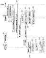
携帯端末3には、図3に示すように、先ず、ユーザの所定操作により稼働条件指示情報が入力される(S1)。図3では、ユーザの操作を白抜きの矢印で示している。稼働条件指示情報は、携帯端末3に所定の操作を行うことで入力される。携帯制御部31は、入力された稼働条件指示情報を第2の記憶部33に記憶させる。 As shown in FIG. 3, first, the operating condition instruction information is input to themobile terminal 3 by a predetermined operation of the user (S1). In FIG. 3, the user's operation is indicated by a white arrow. The operating condition instruction information is input to themobile terminal 3 by performing a predetermined operation. Themobile control unit 31 stores the input operating condition instruction information in thesecond storage unit 33.

本実施の形態では、ユーザが稼働条件指示情報を携帯端末3に入力するために、携帯端末3は、図4に示すように、携帯表示部35に稼働条件指示情報の入力用画面350を表示させるように構成されている。入力用画面350には、稼働条件指示情報の入力欄として、ユーザを特定するための情報であるユーザプロファイルの入力欄351が設けられている。入力欄351に入力される情報としては、例えば、ユーザの氏名、住所及び電話番号が挙げられる。携帯制御部31は、入力されたユーザプロファイルを稼働条件指示情報として、第2の記憶部33に記憶させる。 In the present embodiment, in order for the user to input the operating condition instruction information to themobile terminal 3, themobile terminal 3 displays the operation condition instructioninformation input screen 350 on themobile display unit 35 as shown in FIG. It is configured to let you. Theinput screen 350 is provided with a userprofile input field 351 which is information for identifying a user as an input field for operating condition instruction information. Examples of the information input in theinput field 351 include a user's name, address, and telephone number. Themobile control unit 31 stores the input user profile as operating condition instruction information in thesecond storage unit 33.

稼働条件指示情報が入力された後、ユーザが所定操作することで、携帯制御部31は、入力された稼働条件指示情報を車載装置2側へ転送すべき稼働条件指示情報として設定する(S2)。具体的には、携帯制御部31は、図4に示すように、携帯表示部35の画面に表示された入力用画面350に設定ボタン353が表示される。携帯制御部31は、設定ボタン353がユーザによってタッチ操作されることにより、入力された稼働条件指示情報としてのユーザプロファイルを、設定された稼働条件指示情報として第2の記憶部33に記憶させる。 After the operating condition instruction information is input, themobile control unit 31 sets the input operating condition instruction information as the operating condition instruction information to be transferred to the in-vehicle device 2 side by performing a predetermined operation (S2). .. Specifically, as shown in FIG. 4, themobile control unit 31 displays thesetting button 353 on theinput screen 350 displayed on the screen of themobile display unit 35. When thesetting button 353 is touch-operated by the user, themobile control unit 31 stores the user profile as the input operating condition instruction information in thesecond storage unit 33 as the set operating condition instruction information.

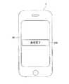
稼働条件指示情報の設定が行われた後、図5に示すように、携帯端末3を車載通信機22に近づけることを促すアテンション画面354の表示を行う(S3)。携帯端末3は、アテンション画面354の表示を行うとともに、第1の無線データを検出するためのスキャン動作を開始する。 After the operating condition instruction information is set, as shown in FIG. 5, theattention screen 354 for prompting themobile terminal 3 to come closer to the in-vehicle communication device 22 is displayed (S3). Themobile terminal 3 displays theattention screen 354 and starts a scanning operation for detecting the first wireless data.

ユーザは、アテンション画面354の表示に従って、携帯端末3を車載通信機22に近づける(S4)。 The user brings themobile terminal 3 closer to the in-vehicle communication device 22 according to the display on the attention screen 354 (S4).

車載装置2は、電源が入力されると、車載通信機22の第1の発信機221が、発信信号強度の情報を含んだ第1の無線データの発信状態と、第1の無線データの発信停止状態とを、所定の時間間隔で繰り返す。携帯端末3が車載通信機22と所定の距離内にあれば、携帯端末3の第2の受信機362は、第1の無線データの受信が可能となる。第1の無線データの受信が可能な所定の距離としては、例えば、数メートルとすることができる。そして、携帯端末3では、判定部32が、第1の無線データを受信した受信信号強度の情報と、第1の無線データに含まれる発信信号強度の情報とから、携帯端末3と車載装置2との距離が所定の値D以下であるか否かを判定する判定処理を行う(S5)。携帯端末3と車載装置2との距離が所定の値D以下であると判定した場合、携帯制御部31は、第2の発信機361により、稼働条件指示情報及びトリガー情報を含む第2の無線データを発信する(S6)。所定の値Dとしては、例えば0.05m以下が挙げられる。第2の発信機361は、一定期間の間、所定の時間間隔で第2の無線データを発信する。図3では、無線データ送信を黒矢印で示している。携帯制御部31は、図6に示すように、第2の無線データの発信中に「送信中」の送信ポップアップ画面355の表示を携帯表示部35にて行う(S7)。 When the power is input to the in-vehicle device 2, thefirst transmitter 221 of the in-vehicle communication device 22 transmits the first radio data including the transmission signal strength information and the first radio data. The stopped state is repeated at predetermined time intervals. If themobile terminal 3 is within a predetermined distance from the in-vehicle communication device 22, thesecond receiver 362 of themobile terminal 3 can receive the first wireless data. The predetermined distance at which the first radio data can be received can be, for example, several meters. Then, in themobile terminal 3, thedetermination unit 32 uses the information on the received signal strength for receiving the first wireless data and the information on the transmitted signal strength included in the first wireless data to determine themobile terminal 3 and the in-vehicle device 2. A determination process for determining whether or not the distance from the user is equal to or less than a predetermined value D is performed (S5). When it is determined that the distance between themobile terminal 3 and the in-vehicle device 2 is equal to or less than a predetermined value D, themobile control unit 31 uses the second transmitter 361 to perform a second radio including operating condition instruction information and trigger information. Send data (S6). Examples of the predetermined value D include 0.05 m or less. The second transmitter 361 transmits the second radio data at predetermined time intervals for a certain period of time. In FIG. 3, wireless data transmission is indicated by a black arrow. As shown in FIG. 6, themobile control unit 31 displays the “transmitting” transmission pop-upscreen 355 on themobile display unit 35 during the transmission of the second wireless data (S7).

一方、判定処理において、判定部32が、携帯端末3と車載装置2との距離が所定の値Dを超えていると判定した場合、携帯制御部31は、第2の無線データを発信することなく、繰り返し第1の無線データを受信して判定処理を行う。携帯制御部31は、繰り返し判定処理を実施している間も図5に示すアテンション画面354の表示を継続して行う。 On the other hand, when thedetermination unit 32 determines in the determination process that the distance between themobile terminal 3 and the in-vehicle device 2 exceeds a predetermined value D, themobile control unit 31 transmits the second wireless data. Instead, the first radio data is repeatedly received and the determination process is performed. Themobile control unit 31 continues to display theattention screen 354 shown in FIG. 5 while the repetitive determination process is being performed.

携帯制御部31は、一定期間の経過後、第2の無線データの発信を完了させると(S8)、図7に示すように、「送信完了」の完了ポップアップ画面356の表示を携帯表示部35にて行う(S9)。 When themobile control unit 31 completes the transmission of the second wireless data after a certain period of time has elapsed (S8), as shown in FIG. 7, themobile display unit 35 displays the completion pop-upscreen 356 of "transmission completed". (S9).

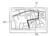
一方、車載装置2側では、車載通信機22の第1の受信機222が第2の無線データを受信すると、トリガー情報に基づいて、制御部211が稼働条件指示情報であるユーザプロファイルを第1の記憶部213に記憶させる。また、制御部211は、図8に示すように、「ユーザプロファイルを受信しました。設定しますか?」という稼働条件設定画面250の表示を車載表示部215にて行う(S10)。稼働条件設定画面250には、「はい」の肯定ボタン251と、「いいえ」の否定ボタン252が表示されている。稼働条件設定画面250の表示に対して、ユーザが「はい」の肯定ボタン251をタッチ操作すると、車載装置2の制御部211は、受信した第2の無線データに含まれている稼働条件指示情報に従って稼働条件を設定する(S11)。具体的には、制御部211は、受信したユーザプロファイルに従って、予め第1の記憶部213に登録されたユーザプロファイルと画面設定情報の対応情報に基づいて車載表示部215に表示される画面の表示条件を設定する。つまり、車載表示部215に表示される画面を、ユーザ好みの画面設定に変更する。次に、制御部211は、ユーザ好みの画面設定において、現在位置取得部214により取得した現在位置をスタートSの位置とし、別途に設定した目的地をゴールGとする経路探索を経路探索部212にて行う(S12)。 On the other hand, on the vehicle-mounteddevice 2 side, when thefirst receiver 222 of the vehicle-mountedcommunication device 22 receives the second radio data, the control unit 211 first sets the user profile which is the operating condition instruction information based on the trigger information. It is stored in thestorage unit 213 of. Further, as shown in FIG. 8, the control unit 211 displays the operatingcondition setting screen 250 as "The user profile has been received. Do you want to set it?" On the vehicle-mounted display unit 215 (S10). On the operatingcondition setting screen 250, a “yes”affirmative button 251 and a “no”negative button 252 are displayed. When the user touches the "Yes"affirmative button 251 with respect to the display of the operatingcondition setting screen 250, the control unit 211 of the in-vehicle device 2 receives the operating condition instruction information included in the second wireless data. The operating conditions are set according to (S11). Specifically, the control unit 211 displays the screen displayed on the vehicle-mounteddisplay unit 215 based on the correspondence information between the user profile and the screen setting information registered in advance in thefirst storage unit 213 according to the received user profile. Set the conditions. That is, the screen displayed on the vehicle-mounteddisplay unit 215 is changed to the screen setting preferred by the user. Next, in the screen setting of the user's preference, the control unit 211 sets the current position acquired by the currentposition acquisition unit 214 as the position of the start S, and sets the destination separately set as the goal G as the route search unit 212. (S12).

経路探索部212が経路探索した後、図9に示すように、ユーザ好みの画面設定にされた車載表示部215において、探索された経路253が表示される。経路253の是非をユーザが判断し、表示した経路253を採用する場合、所定操作が行われ、ナビゲーションが開始する(S13)。その後、車両10が目的地に到着すると、車載装置2の制御部211は、ナビゲーションを終了する(S14)。 After the route search unit 212 searches for a route, as shown in FIG. 9, the searchedroute 253 is displayed on the vehicle-mounteddisplay unit 215 whose screen setting is set to the user's preference. When the user determines the pros and cons of theroute 253 and adopts the displayedroute 253, a predetermined operation is performed and the navigation starts (S13). After that, when thevehicle 10 arrives at the destination, the control unit 211 of the in-vehicle device 2 ends the navigation (S14).

以上に説明した、本実施の形態にかかる情報連携システム1によれば、車載装置2と携帯端末3との距離が所定の値D以下となる状態であれば、携帯端末3で入力された稼働条件指示情報が車載装置2に送信される。情報連携システム1は、車載装置2において、携帯端末3から受信した稼働条件指示情報に基づいて、稼働条件が自動的に設定される。このため、複数のユーザが車載装置2を使用する場合においても、ユーザ毎に稼働条件を車載装置2に入力する手間が省かれる。 According to theinformation linkage system 1 according to the present embodiment described above, if the distance between the in-vehicle device 2 and themobile terminal 3 is equal to or less than a predetermined value D, the operation input by themobile terminal 3 is performed. The condition instruction information is transmitted to the in-vehicle device 2. In theinformation linkage system 1, the in-vehicle device 2 automatically sets the operating conditions based on the operating condition instruction information received from themobile terminal 3. Therefore, even when a plurality of users use the in-vehicle device 2, it is possible to save the trouble of inputting the operating conditions into the in-vehicle device 2 for each user.

また、ユーザが持つ携帯端末3と車載装置2との距離を値D以下にできるように、所定の値Dを小さく設定しておくことで、携帯端末3で車載装置2の稼働条件の設定ができる者を、車内に居る車両10を使用できる者に制限することができる。 Further, by setting a predetermined value D small so that the distance between themobile terminal 3 and the in-vehicle device 2 held by the user can be set to a value D or less, the operating conditions of the in-vehicle device 2 can be set in themobile terminal 3. The person who can do it can be limited to the person who can use thevehicle 10 in the car.

また、第1の受信機222は、必ずしも、センターコンソール101から露出した位置に設置する必要はない。第1の受信機222は、第2の無線データを発信する条件となる携帯端末3と車載装置2との距離として所定の値Dを調整することで、センターコンソール101の表面からセンターコンソール101内に数cmから数10cm入り込んだ位置にも設置することが可能となる。したがって、車載通信機22の取り付け位置によって、車両10のセンターコンソール101及びその周辺部品の設計の自由度が狭められることはない。 Further, thefirst receiver 222 does not necessarily have to be installed at a position exposed from thecenter console 101. Thefirst receiver 222 adjusts a predetermined value D as the distance between themobile terminal 3 and the in-vehicle device 2, which is a condition for transmitting the second wireless data, from the surface of thecenter console 101 to the inside of thecenter console 101. It is possible to install it at a position that is several centimeters to several tens of centimeters in size. Therefore, the mounting position of the in-vehicle communication device 22 does not limit the degree of freedom in designing thecenter console 101 of thevehicle 10 and its peripheral parts.

以下、本実施の形態の変形例1及び変形例2について説明する。 Hereinafter, the modified example 1 and the modified example 2 of the present embodiment will be described.

<変形例1>
変形例1は、上述の情報連携システム1において、車載装置2の第1の発信機221が第1の無線データに車載装置2に予め設定された識別情報を含めて発信できるように構成されている。また、携帯端末3の第2の発信機361は、第2の無線データに、車載装置2から受信した車載装置2の識別情報を含めて発信するように構成されている。そして、車載装置2の制御部211が、第1の受信機222によって受信した第2の無線データに自身の識別情報が含まれている場合に限り、受信した第2の無線データに含まれる稼働条件指示情報を、第1の記憶部213に記憶させる。変形例1は、識別情報を用いて車載装置2の稼働条件指示情報を設定するように制御する構成以外について、上述の情報連携システム1と同様の構成で形成されている。変形例1は、上述の情報連携システム1よりも、よりセキュリティの高い構成とすることができる。
<Modification example 1>
Thefirst modification 1 is configured so that thefirst transmitter 221 of the in-vehicle device 2 can transmit the first wireless data including the identification information preset in the in-vehicle device 2 in the above-mentionedinformation cooperation system 1. There is. Further, the second transmitter 361 of themobile terminal 3 is configured to include the identification information of the vehicle-mounteddevice 2 received from the vehicle-mounteddevice 2 in the second wireless data and transmit the data. Then, only when the control unit 211 of the in-vehicle device 2 includes its own identification information in the second radio data received by thefirst receiver 222, the operation included in the received second radio data. The condition instruction information is stored in thefirst storage unit 213. The modified example 1 is formed in the same configuration as the above-mentionedinformation linkage system 1 except for the configuration in which the operating condition instruction information of the in-vehicle device 2 is controlled to be set by using the identification information. Themodification 1 can have a higher security configuration than the above-mentionedinformation linkage system 1.

<変形例2>
本実施の形態にかかる情報連携システム1、又は変形例1に係る情報連携システムにおいて、携帯端末3の第2の発信機361が、第2の無線データに位置情報取得部34が取得した位置情報を含めて発信し、車載装置2が、現在位置取得部214が取得した現在位置と、携帯端末3から受信した携帯端末3の位置情報とが所定の範囲内にある場合に限り、現在位置から受信した第2の無線データに含まれる稼働条件指示情報に応じて予め設定された目的地までの経路を探索するように設定してもよい。ここでいう所定の範囲は、例えば1.0m以下とすることができる。変形例2は、上述の情報連携システム1よりも、セキュリティを向上させることができる。
<Modification 2>
In theinformation cooperation system 1 according to the present embodiment or the information cooperation system according to the first modification, the position information acquired by the positioninformation acquisition unit 34 in the second radio data by the second transmitter 361 of themobile terminal 3 The current position acquired by the currentposition acquisition unit 214 and the position information of themobile terminal 3 received from themobile terminal 3 are within a predetermined range of the in-vehicle device 2 from the current position. It may be set to search for a route to a preset destination according to the operating condition instruction information included in the received second radio data. The predetermined range referred to here can be, for example, 1.0 m or less.Modification 2 can improve security as compared with the above-mentionedinformation linkage system 1.

<変形例3>
本実施の形態にかかる情報連携システム1、変形例1、又は変形例2に係る情報連携システムにおいて、車載本体部21がオーディオ機能で音楽を再生する際に使用する曲の情報を、ユーザプロファイルとともに又はユーザプロファイルの代わりに、稼働条件指示情報として第2の無線データに含めてもよい。
稼働条件指示情報に、ユーザプロファイルとともに曲の情報を含める場合、図4に示す入力用画面350には、曲の情報の入力欄が設けられることが好ましい。入力欄に入力される曲の情報として、例えば、曲名、歌手名の情報、若しくは作曲者名の情報が挙げられる。なお、携帯端末3に予め複数の曲が記憶されている場合、携帯表示部35に表示された曲名の情報、歌手名の情報、又は作曲者名の情報が、ユーザの所定操作により選択されて、曲の情報として入力されるように構成されてもよい。検索機能により複数の曲のうち、特定の曲の情報を入力する場合、携帯表示部35に曲を表示し、ユーザが特定の位置をタップ操作することで選曲された曲の情報が携帯端末3に入力されるように構成されてもよい。携帯制御部31は、ユーザがタップ操作により選曲した曲の情報を第2の記憶部33に記憶する。
車載装置2の制御部211の稼働設定部218は、受信した曲の情報に従って、音楽を再生できるようにオーディオ機能を設定する。
<Modification example 3>
In the information linkage system according to theinformation linkage system 1, themodification 1, or themodification 2 according to the present embodiment, the information of the song used when the in-vehiclemain unit 21 plays music by the audio function together with the user profile. Alternatively, instead of the user profile, it may be included in the second radio data as operating condition instruction information.
When the song information is included in the operating condition instruction information together with the user profile, it is preferable that theinput screen 350 shown in FIG. 4 is provided with a song information input field. Examples of the song information input in the input field include song title, singer name information, and composer name information. When a plurality of songs are stored in themobile terminal 3 in advance, the song name information, the singer name information, or the composer name information displayed on themobile display unit 35 is selected by a predetermined operation of the user. , May be configured to be input as song information. When inputting information on a specific song among a plurality of songs by the search function, the song is displayed on themobile display unit 35, and the user taps a specific position to display the information on the selected song on themobile terminal 3. It may be configured to be entered in. Themobile control unit 31 stores information on a song selected by the user by tapping in thesecond storage unit 33.
The operation setting unit 218 of the control unit 211 of the in-vehicle device 2 sets the audio function so that the music can be played according to the received song information.

<変形例4>
本実施の形態にかかる情報連携システム1においては、ユーザプロファイルと画面設定情報の対応情報が車載装置2の第1の記憶部213に登録されており、車載装置2の制御部211は、携帯端末3から受信したユーザプロファイルと上記対応情報とに基づいて車載表示部215に表示される画面の表示条件を設定する。この変形例として、上記対応情報を携帯端末3の第2の記憶部33に登録しておき、携帯端末3において、入力されたユーザプロファイルを上記対応情報に基づいてユーザ好みの画面設定情報を特定し、特定したユーザ好みの画面設定情報を稼働条件指示情報として第2の無線データに含めるように、携帯端末3が構成されてもよい。
<Modification example 4>
In theinformation linkage system 1 according to the present embodiment, the correspondence information between the user profile and the screen setting information is registered in thefirst storage unit 213 of the vehicle-mounteddevice 2, and the control unit 211 of the vehicle-mounteddevice 2 is a mobile terminal. The display conditions of the screen displayed on the vehicle-mounteddisplay unit 215 are set based on the user profile received from 3 and the corresponding information. As a modification of this, the correspondence information is registered in thesecond storage unit 33 of themobile terminal 3, and the input user profile is specified in themobile terminal 3 based on the correspondence information. Then, themobile terminal 3 may be configured so as to include the specified screen setting information of the user's preference in the second wireless data as the operating condition instruction information.

以上に説明した本発明は、その精神や主旨または主要な特徴から逸脱することなく、他のいろいろな形で実施することができる。そのため、上述の実施形態はあらゆる点で単なる例示にすぎず、限定的に解釈してはならない。すなわち、上記の実施形態は例にすぎない。 The present invention described above can be practiced in various other forms without departing from its spirit, gist or main features. Therefore, the above embodiments are merely exemplary in all respects and should not be construed in a limited way. That is, the above embodiment is merely an example.

本発明は、車両に搭載される車載装置と携帯端末とを備えた情報連携システムに適用できる。 The present invention can be applied to an information linkage system including an in-vehicle device mounted on a vehicle and a mobile terminal.

1 情報連携システム
2 車載装置
218 稼働設定部
22 車載通信機
221 第1の発信機
222 第1の受信機
3 携帯端末
32 判定部
361 第2の発信機
362 第2の受信機
10 車両

1Information linkage system 2 In-vehicle device 218Operation setting unit 22 In-vehicle communication device 221First transmitter 222First receiver 3Mobile terminal 32 Judgment unit 361Second transmitter 362Second receiver 10 Vehicle

Claims (5)

Translated fromJapanese
車両に搭載される車載装置の第1の記憶部に記憶されるプログラムであって、
発信信号強度の情報を含んだ第1の無線データを発信させ、
前記第1の無線データを受信した携帯端末の受信信号強度と前記第1の無線データの発信信号強度とから前記携帯端末との距離が所定の値又は該所定の値未満の場合に前記携帯端末から発信され、稼働条件を指示する稼働条件指示情報を含んだ第2の無線データを受信させ、
前記稼働条件指示情報に基づいて前記稼働条件を設定させるように前記車載装置を機能させることを特徴とするプログラム。
A program stored in the first storage unit of an in-vehicle device mounted on a vehicle.
The first wireless data including the transmission signal strength information is transmitted,
When the distance from the reception signal strength of the mobile terminal that has received the first wireless data and the transmission signal strength of the first wireless data to the mobile terminal is a predetermined value or less than the predetermined value, the mobile terminal Receives the second radio data including the operating condition instruction information that is transmitted from and instructs the operating conditions.
A program characterized in that the in-vehicle device functions so as to set the operating conditions based on the operating condition instruction information.
前記車載装置は、少なくとも操作情報、地図情報、若しくはPOI情報のいずれか1つを表示する車載表示部をさらに備えており、
前記稼働条件は、前記車載表示部においてユーザ好みの表示を実行させる画面設定情報が含まれる請求項1に記載のプログラム。
The in-vehicle device further includes an in-vehicle display unit that displays at least one of operation information, map information, and POI information.
The program according to claim 1, wherein the operating condition includes screen setting information for executing a user's favorite display on the vehicle-mounted display unit.
前記車載装置は、音楽を再生するオーディオ機能、若しくは動画を再生する動画再生機能のいずれか1つを有しており、
前記稼働条件は、前記オーディオ機能において再生させる曲情報、若しくは前記動画再生機能において再生させる動画情報が含まれる請求項1または請求項2に記載のプログラム。
The in-vehicle device has either an audio function for playing music or a moving image playing function for playing moving pictures.
The program according to claim 1 or 2, wherein the operating condition includes song information to be reproduced by the audio function or moving image information to be reproduced by the moving image reproduction function.
車両に搭載される車載装置の装置制御方法であって、
発信信号強度の情報を含んだ第1の無線データを発信する第1の発信ステップと、
前記第1の無線データを受信した携帯端末の受信信号強度と前記第1の無線データの発信信号強度とから前記携帯端末との距離が所定の値又は該所定の値未満の場合に前記携帯端末から発信され、稼働条件を指示する稼働条件指示情報を含んだ第2の無線データを受信する第1の受信ステップと、
前記稼働条件指示情報に基づいて前記稼働条件を設定する稼働設定ステップと、を有することを特徴とする装置制御方法。
It is a device control method for in-vehicle devices mounted on vehicles.
The first transmission step of transmitting the first wireless data including the transmission signal strength information, and
When the distance from the reception signal strength of the mobile terminal that has received the first wireless data and the transmission signal strength of the first wireless data to the mobile terminal is a predetermined value or less than the predetermined value, the mobile terminal The first receiving step of receiving the second radio data including the operating condition instruction information transmitted from and instructing the operating condition, and
A device control method comprising an operation setting step for setting the operation conditions based on the operation condition instruction information.
携帯端末を制御する端末制御方法であって、
車両に搭載される車載装置から発信信号強度の情報を含んだ第1の無線データを受信する第2の受信ステップと、
前記第1の無線データを受信した受信信号強度と前記第1の無線データの発信信号強度とから前記車載装置との距離を判定する判定ステップと、
前記判定ステップにおいて前記車載装置との距離を所定の値又は該所定の値未満と判定した場合、前記車載装置の稼働条件を設定する稼働条件指示情報を含んだ第2の無線データを発信する第2の発信ステップと、を有することを特徴とする端末制御方法。

It is a terminal control method that controls a mobile terminal.
A second reception step of receiving the first radio data including the transmission signal strength information from the in-vehicle device mounted on the vehicle, and
A determination step of determining the distance to the in-vehicle device from the received signal strength of receiving the first wireless data and the transmission signal strength of the first wireless data.
When the distance to the in-vehicle device is determined to be a predetermined value or less than the predetermined value in the determination step, the second wireless data including the operating condition instruction information for setting the operating conditions of the in-vehicle device is transmitted. A terminal control method comprising two transmission steps.

JP2019220054A2019-12-052019-12-05 Program, device control method and terminal control methodActiveJP6845603B2 (en)

Priority Applications (1)

Application NumberPriority DateFiling DateTitle
JP2019220054AJP6845603B2 (en)2019-12-052019-12-05 Program, device control method and terminal control method

Applications Claiming Priority (1)

Application NumberPriority DateFiling DateTitle
JP2019220054AJP6845603B2 (en)2019-12-052019-12-05 Program, device control method and terminal control method

Related Parent Applications (1)

Application NumberTitlePriority DateFiling Date
JP2017193472ADivisionJP6634056B2 (en)2017-10-032017-10-03 Information cooperation system, in-vehicle device and mobile terminal

Publications (2)

Publication NumberPublication Date
JP2020053987A JP2020053987A (en)2020-04-02
JP6845603B2true JP6845603B2 (en)2021-03-17

Family

ID=69997826

Family Applications (1)

Application NumberTitlePriority DateFiling Date
JP2019220054AActiveJP6845603B2 (en)2019-12-052019-12-05 Program, device control method and terminal control method

Country Status (1)

CountryLink
JP (1)JP6845603B2 (en)

Family Cites Families (6)

* Cited by examiner, † Cited by third party
Publication numberPriority datePublication dateAssigneeTitle
JP2006352409A (en)*2005-06-152006-12-28Matsushita Electric Ind Co Ltd In-vehicle device control system, boarding position information notification device, portable terminal device, and in-vehicle device control device
US20070249288A1 (en)*2006-04-142007-10-25Kamran MoallemiDistance-based security
DE102007003495A1 (en)*2007-01-242008-07-31Siemens Ag Method for distance characterization in inductively coupled access systems
JP5148464B2 (en)*2008-12-012013-02-20富士通テン株式会社 In-vehicle device
JP6089712B2 (en)*2013-01-162017-03-08株式会社デンソー Vehicle control system
US10405163B2 (en)*2013-10-062019-09-03Staton Techiya, LlcMethods and systems for establishing and maintaining presence information of neighboring bluetooth devices

Also Published As

Publication numberPublication date
JP2020053987A (en)2020-04-02

Similar Documents

PublicationPublication DateTitle
US8717198B2 (en)Communication connecting apparatus and method for detecting mobile units in a vehicle
CN101222238B (en)Audio output method for information processing terminal
US8260369B2 (en)Vehicle hands-free communication apparatus and vehicle hands-free communication method
US20110053506A1 (en)Methods and Devices for Controlling Particular User Interface Functions of a Mobile Communication Device in a Vehicle
CN111683349B (en)Vehicle-mounted device, information processing method, and computer-readable recording medium
JP2008278388A (en)Information exchange device and information exchange method
JP2008275544A (en)Information transfer system
US20090270034A1 (en)Devices, methods, and programs for identifying radio communication devices
KR20120079370A (en)Method and apparatus for transmitting data in a mobile terminal
KR101746503B1 (en)Mobile terminal and method for controlling the same
KR20080078300A (en) Car navigation system and its control method
CN107270927A (en)Information display method and device, computer readable storage medium and mobile terminal
US20100144397A1 (en)In-vehicle apparatus, cellular phone device, and method for controlling communication therebetween
JP2008096289A (en)Navigation device compatible with multiple languages
KR20110076520A (en) Car Bluetooth interface device and method
CN104754769B (en)Electronic device and wireless device confirmation method
CN115134455A (en) Electronic equipment cooperation system, contactless charger, control device and method
JP4788561B2 (en) Information communication system
JP6845603B2 (en) Program, device control method and terminal control method
KR20160075976A (en)Apparatus sharing contents and method of operating the same
JP2006120046A (en) In-vehicle information providing apparatus and information providing method
JP6634056B2 (en) Information cooperation system, in-vehicle device and mobile terminal
JP2007116254A (en)Mobile unit with bluetooth (r) communication function
KR101537695B1 (en) Navigation system and method thereof
US20170150532A1 (en)Wireless communication system, information terminal and communication device

Legal Events

DateCodeTitleDescription
A621Written request for application examination

Free format text:JAPANESE INTERMEDIATE CODE: A621

Effective date:20191205

TRDDDecision of grant or rejection written
A01Written decision to grant a patent or to grant a registration (utility model)

Free format text:JAPANESE INTERMEDIATE CODE: A01

Effective date:20210216

A61First payment of annual fees (during grant procedure)

Free format text:JAPANESE INTERMEDIATE CODE: A61

Effective date:20210224

R150Certificate of patent or registration of utility model

Ref document number:6845603

Country of ref document:JP

Free format text:JAPANESE INTERMEDIATE CODE: R150

R250Receipt of annual fees

Free format text:JAPANESE INTERMEDIATE CODE: R250


[8]ページ先頭

©2009-2025 Movatter.jp