JP6841937B2 - Processes and devices for the delivery of fluids by chemical reactions - Google Patents
Processes and devices for the delivery of fluids by chemical reactionsDownload PDFInfo
- Publication number
- JP6841937B2 JP6841937B2JP2019558346AJP2019558346AJP6841937B2JP 6841937 B2JP6841937 B2JP 6841937B2JP 2019558346 AJP2019558346 AJP 2019558346AJP 2019558346 AJP2019558346 AJP 2019558346AJP 6841937 B2JP6841937 B2JP 6841937B2
- Authority
- JP
- Japan
- Prior art keywords
- chamber
- barrel
- configuration
- actuator
- reagent
- Prior art date
- Legal status (The legal status is an assumption and is not a legal conclusion. Google has not performed a legal analysis and makes no representation as to the accuracy of the status listed.)
- Expired - Fee Related
Links
Images


Classifications
- A—HUMAN NECESSITIES
- A61—MEDICAL OR VETERINARY SCIENCE; HYGIENE
- A61M—DEVICES FOR INTRODUCING MEDIA INTO, OR ONTO, THE BODY; DEVICES FOR TRANSDUCING BODY MEDIA OR FOR TAKING MEDIA FROM THE BODY; DEVICES FOR PRODUCING OR ENDING SLEEP OR STUPOR
- A61M5/00—Devices for bringing media into the body in a subcutaneous, intra-vascular or intramuscular way; Accessories therefor, e.g. filling or cleaning devices, arm-rests
- A61M5/178—Syringes
- A61M5/20—Automatic syringes, e.g. with automatically actuated piston rod, with automatic needle injection, filling automatically
- A61M5/2046—Media being expelled from injector by gas generation, e.g. explosive charge
- A—HUMAN NECESSITIES
- A61—MEDICAL OR VETERINARY SCIENCE; HYGIENE
- A61M—DEVICES FOR INTRODUCING MEDIA INTO, OR ONTO, THE BODY; DEVICES FOR TRANSDUCING BODY MEDIA OR FOR TAKING MEDIA FROM THE BODY; DEVICES FOR PRODUCING OR ENDING SLEEP OR STUPOR
- A61M5/00—Devices for bringing media into the body in a subcutaneous, intra-vascular or intramuscular way; Accessories therefor, e.g. filling or cleaning devices, arm-rests
- A61M5/50—Devices for bringing media into the body in a subcutaneous, intra-vascular or intramuscular way; Accessories therefor, e.g. filling or cleaning devices, arm-rests having means for preventing re-use, or for indicating if defective, used, tampered with or unsterile
- A61M5/5086—Devices for bringing media into the body in a subcutaneous, intra-vascular or intramuscular way; Accessories therefor, e.g. filling or cleaning devices, arm-rests having means for preventing re-use, or for indicating if defective, used, tampered with or unsterile for indicating if defective, used, tampered with or unsterile
- A—HUMAN NECESSITIES
- A61—MEDICAL OR VETERINARY SCIENCE; HYGIENE
- A61M—DEVICES FOR INTRODUCING MEDIA INTO, OR ONTO, THE BODY; DEVICES FOR TRANSDUCING BODY MEDIA OR FOR TAKING MEDIA FROM THE BODY; DEVICES FOR PRODUCING OR ENDING SLEEP OR STUPOR
- A61M5/00—Devices for bringing media into the body in a subcutaneous, intra-vascular or intramuscular way; Accessories therefor, e.g. filling or cleaning devices, arm-rests
- A61M5/178—Syringes
- A61M5/20—Automatic syringes, e.g. with automatically actuated piston rod, with automatic needle injection, filling automatically
- A61M2005/2073—Automatic syringes, e.g. with automatically actuated piston rod, with automatic needle injection, filling automatically preventing premature release, e.g. by making use of a safety lock
- A—HUMAN NECESSITIES
- A61—MEDICAL OR VETERINARY SCIENCE; HYGIENE
- A61M—DEVICES FOR INTRODUCING MEDIA INTO, OR ONTO, THE BODY; DEVICES FOR TRANSDUCING BODY MEDIA OR FOR TAKING MEDIA FROM THE BODY; DEVICES FOR PRODUCING OR ENDING SLEEP OR STUPOR
- A61M5/00—Devices for bringing media into the body in a subcutaneous, intra-vascular or intramuscular way; Accessories therefor, e.g. filling or cleaning devices, arm-rests
- A61M5/178—Syringes
- A61M5/31—Details
- A61M2005/3125—Details specific display means, e.g. to indicate dose setting
- A—HUMAN NECESSITIES
- A61—MEDICAL OR VETERINARY SCIENCE; HYGIENE
- A61M—DEVICES FOR INTRODUCING MEDIA INTO, OR ONTO, THE BODY; DEVICES FOR TRANSDUCING BODY MEDIA OR FOR TAKING MEDIA FROM THE BODY; DEVICES FOR PRODUCING OR ENDING SLEEP OR STUPOR
- A61M2205/00—General characteristics of the apparatus
- A61M2205/02—General characteristics of the apparatus characterised by a particular materials
- A61M2205/0216—Materials providing elastic properties, e.g. for facilitating deformation and avoid breaking
- A—HUMAN NECESSITIES
- A61—MEDICAL OR VETERINARY SCIENCE; HYGIENE
- A61M—DEVICES FOR INTRODUCING MEDIA INTO, OR ONTO, THE BODY; DEVICES FOR TRANSDUCING BODY MEDIA OR FOR TAKING MEDIA FROM THE BODY; DEVICES FOR PRODUCING OR ENDING SLEEP OR STUPOR
- A61M2205/00—General characteristics of the apparatus
- A61M2205/75—General characteristics of the apparatus with filters
- A61M2205/7536—General characteristics of the apparatus with filters allowing gas passage, but preventing liquid passage, e.g. liquophobic, hydrophobic, water-repellent membranes
Landscapes
- Health & Medical Sciences (AREA)
- Vascular Medicine (AREA)
- Engineering & Computer Science (AREA)
- Anesthesiology (AREA)
- Biomedical Technology (AREA)
- Heart & Thoracic Surgery (AREA)
- Hematology (AREA)
- Life Sciences & Earth Sciences (AREA)
- Animal Behavior & Ethology (AREA)
- General Health & Medical Sciences (AREA)
- Public Health (AREA)
- Veterinary Medicine (AREA)
- Infusion, Injection, And Reservoir Apparatuses (AREA)
Description
Translated fromJapanese関連出願の相互参照
本出願は、2017年2月17日に出願された米国仮特許出願第62/460,414号に対する優先権を主張し、その開示は参照によりその全体が本明細書に明示的に組み込まれる。Cross-reference to related applications This application claims priority to US Provisional Patent Application No. 62 / 460,414 filed on February 17, 2017, the disclosure of which is expressly provided herein in its entirety. Is incorporated.
本開示は、治療用流体を非経口送達するためのプロセスおよびデバイスに関する。より具体的には、本開示は、ガスを発生させる化学反応による高粘度治療用流体(例えば、タンパク質治療薬)の非経口送達のためのプロセスおよびデバイスに関する。 The present disclosure relates to processes and devices for parenteral delivery of therapeutic fluids. More specifically, the present disclosure relates to processes and devices for parenteral delivery of highly viscous therapeutic fluids (eg, protein therapeutics) by gas-generating chemical reactions.
タンパク質治療薬は、自己免疫障害、心血管疾患、糖尿病、および癌などの広範囲の疾患に対する治療を提供する新たに生まれた分類の薬物療法である。モノクローナル抗体などのいくつかのタンパク質治療薬の一般的な送達方法は、静脈内注入によるものであり、そこでは大量の希釈溶液が経時的に送達される。静脈内注入は、通常、医師または看護師の監督を必要とし、臨床現場で行われる。これは患者にとっては不便であり得、家庭でタンパク質治療薬の送達を可能にするための努力がなされている。望ましくは、タンパク質治療製剤は、静脈内投与を必要とする代わりに皮下送達用の注射器を使用して投与され得る。皮下注射は、一般に、例えば糖尿病患者によるインスリンの投与において、専門家でない人によって投与される。 Protein therapies are a newly born class of drug therapies that provide treatment for a wide range of diseases such as autoimmune disorders, cardiovascular disease, diabetes, and cancer. A common method of delivery of some protein therapeutics, such as monoclonal antibodies, is by intravenous infusion, where large amounts of diluted solution are delivered over time. Intravenous injection usually requires the supervision of a doctor or nurse and is performed in the clinical setting. This can be inconvenient for patients, and efforts have been made to enable delivery of protein therapeutics at home. Desirably, the protein therapeutic formulation can be administered using a syringe for subcutaneous delivery instead of requiring intravenous administration. Subcutaneous injections are generally administered by non-specialists, for example in the administration of insulin by diabetics.
静脈内送達から注射器および注射ペンのような注射デバイスへの治療用タンパク質製剤の移行は、容易で、信頼性があり、かつ患者に最小限の痛みしか引き起こさない様式で高濃度の高分子量分子を送達することと関連付けられた課題に取り組むことを必要とする。これに関して、静脈内バッグは典型的には1リットルの容量を有するが、注射器の標準容量は、0.3ミリリットル〜最大25ミリリットルの範囲である。このように、薬物に応じて、同量の治療用タンパク質を送達するために、濃度を40倍以上増加させなければならない場合がある。また、注射療法は、患者の快適さおよび服薬遵守を目的として、より小さい針直径およびより速い送達時間を目指している。 The transfer of therapeutic protein formulations from intravenous delivery to injection devices such as syringes and pens is easy, reliable, and produces high concentrations of high molecular weight molecules in a manner that causes minimal pain to the patient. Need to address the challenges associated with delivery. In this regard, intravenous bags typically have a capacity of 1 liter, but standard volumes of syringes range from 0.3 ml up to 25 ml. Thus, depending on the drug, the concentration may need to be increased by a factor of 40 or more to deliver the same amount of therapeutic protein. Injection therapy also aims for smaller needle diameters and faster delivery times for patient comfort and compliance.
タンパク質治療薬の送達もまた、かかる治療製剤と関連付けられた高い粘度、およびかかる製剤を、非経口デバイスを通して押し出すのに必要とされる高い力のために困難である。40〜60センチポアズ(cP)を超える絶対粘度を有する製剤は、複数の理由で従来のばね駆動自動注入器によって送達することが困難であり得る。構造的には、送達される圧力または力の量に対するばねの設置面積は、比較的大きく、特定の形状に固定されているため、送達デバイスの設計の柔軟性を低下させる。次に、自動注入器は、通常プラスチック部品から作られる。しかしながら、高粘度の流体を確実に送達するためには、大量のエネルギーをばね内に蓄える必要がある。適切に設計されていない場合、この蓄えられたエネルギーが、プラスチック部品が応力下で永久的に変形する傾向であるクリープによりプラスチック部品に損傷を与える可能性がある。自動注入器は、典型的には、ばねを使用して、針含有内部構成要素を注射器のハウジングの外縁に向かって押すことによって動作する。ばね式自動注入器の操作と関連付けられた音は、患者の不安を引き起こし、将来の服薬遵守を低下させる可能性がある。このようなばね駆動式自動注入器の発生圧力対時間プロファイルは、容易に修正することができず、これはユーザが彼らの送達ニーズを満たすために圧力を微調整することを妨げる。 Delivery of protein therapeutics is also difficult due to the high viscosity associated with such therapeutic formulations and the high force required to push such formulations through parenteral devices. Formulations with absolute viscosities greater than 40-60 centipoise (cP) can be difficult to deliver by conventional spring-driven automatic injectors for a number of reasons. Structurally, the footprint of the spring relative to the amount of pressure or force delivered is relatively large and fixed in a particular shape, reducing the design flexibility of the delivery device. Second, automatic injectors are usually made from plastic parts. However, in order to reliably deliver a highly viscous fluid, it is necessary to store a large amount of energy in the spring. If not properly designed, this stored energy can damage the plastic part by creep, which tends to permanently deform the plastic part under stress. The automatic injector typically operates by using a spring to push the needle-containing internal component toward the outer edge of the syringe housing. The sounds associated with the operation of the spring-loaded automatic injector can cause patient anxiety and reduce future medication compliance. The generated pressure vs. time profile of such spring driven automatic injectors cannot be easily modified, which prevents users from fine-tuning the pressure to meet their delivery needs.
治療用流体、特に高粘度流体を妥当な時間内に限られた注入スペースで自己投与することができるプロセスおよびデバイスを提供することが望ましいであろう。これらのプロセスおよびデバイスは、高濃度タンパク質、高粘度医薬製剤、または他の治療用流体を送達するために使用され得る。 It would be desirable to provide processes and devices that allow therapeutic fluids, especially high viscosity fluids, to be self-administered in a limited injection space within a reasonable time. These processes and devices can be used to deliver high-concentration proteins, high-viscosity pharmaceutical formulations, or other therapeutic fluids.
本開示は、ガスを発生させる化学反応による治療用流体、特に高粘度治療用流体(例えば、タンパク質治療薬)の非経口送達のためのプロセスおよびデバイスを提供する。デバイスは、第1の試薬を収容する第1の作動チャンバ、第2の試薬を収容する第2の反応チャンバ、および治療用流体を収容する第3の治療用流体チャンバを含み得る。装填構成において、プランジャは、第1のチャンバを第2のチャンバから分離する。送達構成において、プランジャは、第1のチャンバからの第1の試薬が第2のチャンバからの第2の試薬と連通し、かつ反応することを可能にする。発生したガスは、プランジャに作用して、第3のチャンバから治療用流体を送達する。 The present disclosure provides processes and devices for parenteral delivery of therapeutic fluids, in particular high viscosity therapeutic fluids (eg, protein therapeutics), by chemical reactions that generate gases. The device may include a first working chamber containing a first reagent, a second reaction chamber containing a second reagent, and a third therapeutic fluid chamber containing a therapeutic fluid. In the loading configuration, the plunger separates the first chamber from the second chamber. In the delivery configuration, the plunger allows the first reagent from the first chamber to communicate and react with the second reagent from the second chamber. The generated gas acts on the plunger to deliver the therapeutic fluid from the third chamber.
本開示の実施形態によれば、化学反応によって治療用流体を送達するためのデバイスが開示される。デバイスは、第1のチャンバ、第2のチャンバ、および第3のチャンバを有するバレルと、バレルの第1のチャンバと第2のチャンバとの間に配置されたピストンと、ピストンを移動させるように構成されたばねと、バレルの第2のチャンバと第3のチャンバの間に配置されたプランジャと、アクチュエータと、を含む。アクチュエータは、アクチュエータがバレルに対して軸方向に移動することが防止されるロック構成と、アクチュエータがバレルに対して軸方向に移動することができる非ロック構成と、アクチュエータがバレルに対して軸方向に移動する送達構成と、を有する。ロック構成および非ロック構成において、第1のチャンバは第1の試薬を収容し、第2のチャンバは第2の試薬を収容し、かつピストンによって第1のチャンバから分離され、第3のチャンバが治療用流体を収容する。送達構成において、ばねがピストンを移動させて、第1のチャンバを第2のチャンバと連通させ、第1および第2の試薬が反応し、プランジャを駆動して治療用流体を第3のチャンバから送達するガスを発生する。 According to the embodiments of the present disclosure, a device for delivering a therapeutic fluid by a chemical reaction is disclosed. The device moves a barrel having a first chamber, a second chamber, and a third chamber, a piston disposed between the first and second chambers of the barrel, and a piston. It includes a configured spring, a plunger placed between the second and third chambers of the barrel, and an actuator. The actuator has a lock configuration that prevents the actuator from moving axially with respect to the barrel, an unlocked configuration that allows the actuator to move axially with respect to the barrel, and an actuator axially relative to the barrel. It has a delivery configuration that moves to. In the locked and unlocked configurations, the first chamber contains the first reagent, the second chamber contains the second reagent, and is separated from the first chamber by a piston, with the third chamber Contains therapeutic fluid. In the delivery configuration, a spring moves the piston to communicate the first chamber with the second chamber, the first and second reagents react, driving the plunger to drive the therapeutic fluid from the third chamber. Generates the gas to be delivered.
本開示の別の実施形態によれば、化学反応によって治療用流体を送達するためのデバイスが開示される。デバイスは、第1のチャンバ、第2のチャンバ、および第3のチャンバを有するバレルと、バレルの第1のチャンバと第2のチャンバとの間に配置されたピストンと、ピストンを移動させるように構成されたばねと、バレルの第2のチャンバと第3のチャンバの間に配置されたプランジャと、第1の構成と第2の構成との間でバレルに対して回転するように構成されたアクチュエータと、を含む。第1の構成において、第1のチャンバは、第1の試薬を収容し、第2のチャンバは、第2の試薬を収容し、かつピストンによって第1のチャンバから分離され、第3のチャンバは、治療用流体を収容する。第2の構成において、ばねは、ピストンを移動させて、第1のチャンバを第2のチャンバと連通させ、第1および第2の試薬が反応し、プランジャを駆動して治療用流体を第3のチャンバから送達するガスを発生する。 According to another embodiment of the present disclosure, a device for delivering a Therapeutic fluid by a chemical reaction is disclosed. The device moves a barrel having a first chamber, a second chamber, and a third chamber, a piston located between the first and second chambers of the barrel, and a piston. A spring configured, a plunger located between the second and third chambers of the barrel, and an actuator configured to rotate with respect to the barrel between the first and second configurations. And, including. In the first configuration, the first chamber contains the first reagent, the second chamber contains the second reagent and is separated from the first chamber by a piston, and the third chamber , Contain the therapeutic fluid. In the second configuration, the spring moves the piston to communicate the first chamber with the second chamber, the first and second reagents react, and drive the plunger to drive the therapeutic fluid into the third. Generates gas to be delivered from the chamber.
本開示の別の実施形態によれば、化学反応によって治療用流体を送達するためのデバイスが開示される。本デバイスは、第1の試薬を収容する第1のチャンバと、第2の試薬および吸収性粉末を収容する第2のチャンバと、治療用流体を収容する第3のチャンバと、を有するバレル、バレルの第1のチャンバと第2のチャンバとの間に配置されたピストン、バレルの第2のチャンバと第3のチャンバとの間に配置されたプランジャ、およびピストンを移動させて、第1のチャンバを第2のチャンバと連通させるように構成されたアクチュエータを含み、第1の試薬および第2の試薬が反応し、液体混合物およびガスを形成し、液体混合物の少なくとも一部分が、吸収性粉末によって吸収され、ガスがプランジャを駆動して、第3のチャンバから治療用流体を送達する。 According to another embodiment of the present disclosure, a device for delivering a Therapeutic fluid by a chemical reaction is disclosed. The device has a barrel comprising a first chamber containing a first reagent, a second chamber containing a second reagent and an absorbent powder, and a third chamber containing a therapeutic fluid. The first chamber is moved by moving the piston located between the first and second chambers of the barrel, the plunger located between the second and third chambers of the barrel, and the piston. It comprises an actuator configured to communicate the chamber with the second chamber, the first and second reagents react to form a liquid mixture and gas, at least a portion of the liquid mixture by an absorbent powder. As absorbed, the gas drives the plunger to deliver the therapeutic fluid from the third chamber.
本開示のさらに別の実施形態によれば、化学反応によって治療用流体を送達するためのデバイスが開示される。デバイスは、装填構成および送達構成を有する。本デバイスは、バレルと、装填構成と送達構成との間でバレルに対して第1の長手方向において移動するアクチュエータと、装填構成と送達構成との間でアクチュエータの第1の長手方向と反対側の第2の長手方向において移動するピストンと、送達構成から第2の長手方向におけるアクチュエータの移動を防止するロック機構と、を含む。 According to yet another embodiment of the present disclosure, a device for delivering a Therapeutic fluid by a chemical reaction is disclosed. The device has a loading configuration and a delivery configuration. The device is an actuator that moves between the barrel and the loading configuration and the delivery configuration in the first longitudinal direction with respect to the barrel, and between the loading configuration and the delivery configuration on the side opposite to the first longitudinal direction of the actuator. Includes a piston that moves in the second longitudinal direction of the, and a locking mechanism that prevents the actuator from moving in the second longitudinal direction from the delivery configuration.
本開示の上述および他の特徴および利点、ならびにそれらを達成する様式は、本発明の実施形態の以下の説明を添付の図面と併せて参照することによってより明らかになり、またよりよく理解されることとする。 The above and other features and advantages of the present disclosure, as well as the modalities for achieving them, will become clearer and better understood by reference to the following description of embodiments of the invention in conjunction with the accompanying drawings. I will do it.
複数の図面全体を通して、対応する参照符号は、対応する部品を示す。本明細書に記載される例証は、本発明の例示の実施形態を例示し、そのような例証は、いかなる様式においても本発明の範囲を限定するものと解釈されるべきではない。 Throughout the drawings, the corresponding reference numerals indicate the corresponding parts. The illustrations described herein exemplify exemplary embodiments of the invention, and such illustrations should not be construed as limiting the scope of the invention in any manner.
本開示は、高粘度治療用流体の非経口送達のためのプロセスおよびデバイスに関する。デバイスは、1つ以上の試薬間の化学反応を通してデバイス内にガスを発生させることによって駆動される。好適なデバイスは、例えば、注射器または自動注入ペンを含み得る。 The present disclosure relates to processes and devices for parenteral delivery of high viscosity therapeutic fluids. The device is driven by generating gas within the device through a chemical reaction between one or more reagents. Suitable devices may include, for example, a syringe or an automatic infusion pen.
1.治療用流体
本開示のデバイスから分配される治療用流体は、溶液、分散液、懸濁液、エマルジョン、または他の好適な流体形態等の、様々な形態をとり得る。1. 1. Therapeutic Fluids The Therapeutic fluids dispensed from the devices of the present disclosure may take various forms, such as solutions, dispersions, suspensions, emulsions, or other suitable fluid forms.
治療用流体は、治療上有用な薬剤を含有し得る。ある実施形態において、薬剤は、モノクローナル抗体等のタンパク質、または治療上有用ないくつかの他のタンパク質である。いくつかの実施形態において、タンパク質は、治療用流体中で約75mg/mL〜約500mg/mLの濃度を有し得る。ある実施形態において、タンパク質は、約150mg/mL、200mg/mL、250mg/mL、またはそれ以上の濃度を有し得る。治療用流体は、水、ペルフルオロアルカン溶媒、ベニバナ油、または安息香酸ベンジル等の、溶媒または非溶媒をさらに含有してもよい。 Therapeutic fluids may contain therapeutically useful agents. In certain embodiments, the agent is a protein, such as a monoclonal antibody, or some other therapeutically useful protein. In some embodiments, the protein can have a concentration of about 75 mg / mL to about 500 mg / mL in the therapeutic fluid. In certain embodiments, the protein can have concentrations of about 150 mg / mL, 200 mg / mL, 250 mg / mL, or higher. The therapeutic fluid may further contain solvent or non-solvents such as water, perfluoroalkane solvent, safflower oil, or benzyl benzoate.
治療用流体は、高粘度流体と見なすことができ、約5cP〜約1000cPの絶対粘度を有し得る。ある実施形態において、高粘度流体は、少なくとも約10cP、20cP、30cP、40cP、50cP、60cP、またはそれ以上の絶対粘度を有する。 The therapeutic fluid can be considered a high viscosity fluid and can have an absolute viscosity of about 5 cP to about 1000 cP. In certain embodiments, the high viscosity fluid has an absolute viscosity of at least about 10 cP, 20 cP, 30 cP, 40 cP, 50 cP, 60 cP, or higher.
いくつかの実施形態において、治療用流体は、限定されるわけではないが、インスリン、インスリンリスプロまたはインスリングラルギン等のインスリン類似体、インスリン誘導体、デュラグルチドまたはリラグルチド等のグルカゴン様ペプチド(GLP−1)受容体アゴニスト、グルカゴン、グルカゴン類似体、グルカゴン誘導体、胃抑制ポリペプチド(GIP)、GIP類似体、GIP誘導体、オキシントモジュリン類似体、オキシントモジュリン誘導体、治療用抗体、および本開示のデバイスによって送達することができる任意の治療薬を含む、1つ以上の薬物または治療薬を含み得る。デバイス内で使用される薬物は、1つ以上の賦形剤と共に処方されてもよい。デバイスは、本明細書に概して記載されているように、患者、介護者、または医療従事者によって、人に薬物を送達する様式で操作される。 In some embodiments, the therapeutic fluid is, but is not limited to, insulin analogs such as insulinotropic or insulin glargine, insulin derivatives, glucagon-like peptides (GLP-1) such as duraglutide or liraglutide. Delivered by body agonists, glucagon, glucagon analogs, glucagon derivatives, gastric inhibitory polypeptides (GIP), GIP analogs, GIP derivatives, oxintomodulin analogs, oxintomodulin derivatives, therapeutic antibodies, and devices of the present disclosure. It may include one or more drugs or therapeutic agents, including any therapeutic agent that can. The drug used in the device may be formulated with one or more excipients. The device is operated by a patient, caregiver, or healthcare professional in a manner that delivers the drug to a person, as generally described herein.
2.ガス発生化学反応
本開示のデバイスにおいてガスを発生させるために、任意の好適な化学試薬を使用することができる。発生ガスの例には、二酸化炭素ガス、窒素ガス、酸素ガス、塩素ガスなどが含まれる。望ましくは、発生ガスは、不活性、かつ不燃性である。デバイスを操作するために必要なガスの量は、デバイス内で使用される各試薬のタイプ、量、および濃度に影響を与える可能性がある。試薬は、乾燥形態(例えば、粉末形態、錠剤形態)および/または液体形態であり得る。2. 2. Gas Generation Chemical Reactions Any suitable chemical reagent can be used to generate gas in the devices of the present disclosure. Examples of the generated gas include carbon dioxide gas, nitrogen gas, oxygen gas, chlorine gas and the like. Desirably, the generated gas is inert and nonflammable. The amount of gas required to operate the device can affect the type, amount, and concentration of each reagent used within the device. The reagents can be in dry form (eg, powder form, tablet form) and / or liquid form.
例示的な一実施形態において、重炭酸塩(これは乾燥形態で存在し得る)が酸(これは液体形態で存在し得る)と反応して、デバイス内に二酸化炭素ガスを発生する。好適な重炭酸塩の例には、重炭酸ナトリウム、重炭酸カリウム、および重炭酸アンモニウムを含む。珪藻土等の他の成分もまた、重炭酸塩と共に存在してもよい。好適な酸の例には、酢酸、クエン酸、酒石酸水素カリウム、ピロリン酸二ナトリウム、およびリン酸二水素カルシウムを含む。特定の一例において、重炭酸塩は重炭酸カリウムであり、酸はクエン酸水溶液であり、反応して、二酸化炭素ガスと、水と溶解したクエン酸カリウムとの液体混合物と、を生成し得る。 In one exemplary embodiment, bicarbonate (which can be present in dry form) reacts with acid (which can be present in liquid form) to generate carbon dioxide gas in the device. Examples of suitable bicarbonates include sodium bicarbonate, potassium bicarbonate, and ammonium bicarbonate. Other components such as diatomaceous earth may also be present with bicarbonate. Examples of suitable acids include acetic acid, citric acid, potassium hydrogen tartrate, disodium pyrophosphate, and calcium dihydrogen phosphate. In a particular example, the bicarbonate is potassium bicarbonate and the acid is an aqueous solution of citric acid, which can react to produce a liquid mixture of carbon dioxide gas and dissolved potassium citrate.
本開示のデバイスを駆動するために他の反応が使用されてもよい。一例において、炭酸銅または炭酸カルシウム等の金属炭酸塩が、熱分解されて、デバイス内に二酸化炭素ガスおよび対応する金属酸化物を生成する。別の例において、2,2’−アゾビスイソブチロニトリル(AIBN)を加熱して、デバイス内に窒素ガスを生成する。さらに別の例において、酵素(例えば、イースト)を糖と反応させて、デバイス内に二酸化炭素ガスを生成する。いくつかの物質は、容易に昇華し、固体から気体になる。かかる物質には、ナフタレン、ヨウ素が含まれるが、これらに限定されない。さらに別の例において、過酸化水素を、酵素(例えばカタラーゼ)または二酸化マンガン等の触媒で分解して、デバイス内に酸素ガスを生成する。さらに別の例において、塩化銀を、光に曝すことによって分解して、デバイス内にガスを発生する。本開示のデバイスを駆動するために使用される好適な試薬、化学製剤、および反応は、米国特許出願第14/434,586号(米国特許公開第2015/0314070号)表題「Chemical Engines and Methods for Their Use,Especially in the Injection of Highly Viscous Fluids」にさらに記載され、その開示内容は、その全体が参照により本明細書に明示的に組み込まれる。 Other reactions may be used to drive the devices of the present disclosure. In one example, a metal carbonate such as copper carbonate or calcium carbonate is pyrolyzed to produce carbon dioxide gas and the corresponding metal oxide in the device. In another example, 2,2'-azobisisobutyronitrile (AIBN) is heated to produce nitrogen gas in the device. In yet another example, an enzyme (eg, yeast) is reacted with sugar to produce carbon dioxide gas in the device. Some substances easily sublimate from solids to gases. Such substances include, but are not limited to, naphthalene and iodine. In yet another example, hydrogen peroxide is decomposed with a catalyst such as an enzyme (eg, catalase) or manganese dioxide to produce oxygen gas in the device. In yet another example, silver chloride is decomposed by exposure to light to generate gas in the device. Suitable reagents, chemicals, and reactions used to drive the devices of the present disclosure are described in US Patent Application No. 14 / 434,586 (US Patent Publication No. 2015/0314070), entitled "Chemical Engines and Methods for". Further described in "Their Use, Specially in the Injection of High High Viscous Fluids", the disclosure of which is expressly incorporated herein by reference in its entirety.
3.第1の送達デバイス
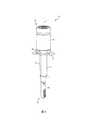
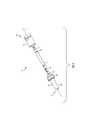
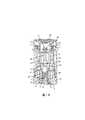
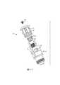
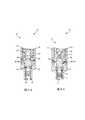
図1〜図3は、本開示の第1の例示的な送達デバイス100を示す。例示的なデバイス100は、第1の遠位端102(例示的には下端)から第2の近位端104(例示的には上端)まで長手方向軸Lに沿って延在する細長い構造体である。例示的なデバイス100は、第1の端部102に位置付けられた針注射器110と、第2の端部104に位置付けられたアクチュエータ組立体120と、それらの間に位置付けられた下部ハウジングまたはアダプタ130と、を備える実質的に円筒形のバレルもしくはハウジング106を含む。これらの構成要素は、以下でさらに説明される。アクチュエータ組立体120は、例示的に注射器110に結合されながら、アクチュエータ組立体120は、代替的に、自動注入ペンまたは他の好適な送達デバイスを伴い使用され得る。3. 3. First Delivery Device Figures 1-3 show the first
デバイス100の注射器110は、ガラス、プラスチック、または他の好適な材料で構成することができる。図2および図3に示されるように、例示的な注射器110は、アダプタ130の内側肩部132上に載置されるように構成された上部リム112を含む。注射器110の上部リム112の下には、注射器110とアダプタ130との間の動きを減衰させるためにダンパ114が提供されてもよい。ダンパ114は、注射器110および/またはアダプタ130に一体的に結合(例えば、オーバーモールド)されてもよい。代替的に、ダンパ114は、別個の構成要素(例えば、Oリング)であり得る。注射器110の上部リム112の上に、封止部115(例えば、Oリング)を提供して、注射器110とアクチュエータ組立体120との間の接続部を封止することができる。例示的な注射器110はまた、プランジャ116、針117、および針117を覆う保護端部キャップ118を含む。 The
デバイス100のアダプタ130は、比較的小さい内径を有する下部シャフト134と、比較的大きい内径を有する上部ヘッド136と、を含む。内側肩部132は、上述したように、シャフト134とアダプタ130のヘッド136との間に位置付けられて、注射器110のリム112を受容する。アダプタ130は、所望の注射器110を受容するようにサイズ決定され、かつ成形されてもよい。例えば、シャフト134の内径は、所望の注射器110の外径を収容するようにサイズ決定され、かつ成形されてもよい。組み立てられると、アダプタ130のシャフト134は、下向きに延在して、注射器110の少なくとも一部を囲んで支持し、ヘッド136は、上向きに延在して、アクチュエータ組立体120と結合する。例解された実施形態において、アダプタ130のヘッド136は、外側に螺合され、アクチュエータ組立体120は、内側に螺合され、そのためアダプタ130は、アクチュエータ組立体120とねじ結合される。アダプタ130をアクチュエータ組立体120に、スナップ嵌め、摩擦嵌め、または他の方法で結合することもまた本開示の範囲内である。アダプタ130はまた、フランジ138(図1)、例示的に楕円形状のフランジを含むことができ、これはユーザのための把持面として機能するように半径方向外向きに延在する。 The
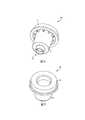
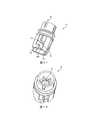
デバイス100のアクチュエータ組立体120は、図4により詳細に示される。例示的なアクチュエータ組立体120は、長手方向軸Lに沿って配置された以下の構成要素:下部プラグ140、下部混合チャンバ150、上部混合チャンバ160、らせん状のばね170、ピストン180、アクチュエータシャトル190、上部プラグまたはねじ200、上部ハウジング210、後退防止(ABD)リング220、およびアクチュエータボタン230を含む。これらの構成要素の各々は、以下にさらに説明される。 The
下部プラグ140を、図5に示す。例示的なプラグ140は、図18に示されるように、注射器110内で受容するようにサイズ決定された比較的大きいヘッド141、および下部混合チャンバ150内で受容するようにサイズ決定された比較的小さいシャフト142を有する。下部プラグ140は、熱可塑性エラストマ(TPE)または別の好適な材料で構成され得る。 The
下部混合チャンバ150を、図6および図7に示す。例示的な下部混合チャンバ150は、比較的小さい内径を有する下部分151と、比較的大きい内径を有する上部分152と、を含む。下側混合チャンバ150の下部分151は、図18に示されるように、下部プラグ140を受容するようにサイズ決定された下部ポートまたは孔153を画定する。また、封止部115は、下部混合チャンバ150の下部分151の周りに嵌合するようにサイズ決定される。下部混合チャンバ150の上部分152は、図18に示されるように、ばね170およびピストン180を受容するようにサイズ決定される。下部混合チャンバ150は、ガラス強化高密度ポリエチレン(HDPE)、ガラス強化ポリプロピレン、または別の好適な材料で構成することができる。 The
上部混合チャンバ160を、図8および図9に示す。例示的な上部混合チャンバ160は、図18に示されるように、下部混合チャンバ150に結合(例えば、超音波溶接)される。混合チャンバ150、160が、一体的に共に形成され得ることも本開示の範囲内である。上部混合チャンバ160は、下部混合チャンバ150よりも大きい内径を有し、図18に示されるようにシャトル190を受容するようにサイズ決定される。上部混合チャンバ160は、ピストン180と相互作用するように半径方向内向きに延在する1つ以上のロックタブ161と、シャトル190と相互作用するように半径方向内向きに延在する1つ以上のガイドキー162と、を含む。より具体的には、例示的な上部混合チャンバ160は、互いに180度離れて配置された2つのロックタブ161と、互いに180度離れて配置された2つのガイドキー162と、を含む(図21も参照)。ロックタブ161は、ピストン180に達するために半径方向に比較的長くてもよく、一方ガイドキー162は、シャトル190に達するために半径方向に比較的短くてもよい。上側混合チャンバ160はまた、上部ハウジング210と相互作用するように上向きに延在する1つ以上の位置合わせキー163を含み、例示的に、比較的広い第1の位置合わせキー163A、比較的狭い第2の位置合わせキー163B、ならびに比較的高く、かつ狭く、その端部に結合タブ164を備える、第3の位置合わせキー163C、および第4の位置合わせキー163Dも含む。上部混合チャンバ160は、ガラス強化HDPE、ガラス強化ポリプロピレン、または別の好適な材料で構成することができる。 The
ピストン180を、図10に示す。例示的なピストン180は、図18に示されるように、封止部181(例えば、Oリング)によって囲まれて、下部混合チャンバ150の内壁への封止インターフェースを提供する。ピストン180は、回転ツール(図示せず)と相互作用するように上方を向く、ツール係合特徴部、例示的には交差スロット182を含む。ピストン180はまた、上部混合チャンバ160のロックタブ161と相互作用するように半径方向外向きに延在する1つ以上のロックタブ183と、シャトル190と相互作用するように半径方向外向きに延在する1つ以上の回転タブ184と、を含む。より具体的には、例示的なピストン180は、互いに180度離れて配置された2つのロックタブ183と、互いに180度離れて配置された2つの回転タブ184と、を含む。各回転タブ184は、上部傾斜面185を有する。ピストン180は、ガラス強化HDPE、ガラス強化ポリプロピレン、または別の好適な材料で構成することができる。 The
シャトル190を、図11および図12に示す。例示的なシャトル190は、図18に示されるように、封止部191(例えば、Oリング)によって囲まれて、上部混合チャンバ160の内壁への封止インターフェースを提供する。シャトル190は、その外面に沿って、1つ以上の階段状のキー溝192を含み、各キー溝192は下部垂直部分192A、中間水平部分192B、および上部垂直部分192Cを有する。キー溝192の中間水平部分192Bは、上壁または停止面193によって境界を定められてもよい。図18に示されるように、シャトル190は、その上端で、上部プラグ200を受容するようにサイズ決定された上部ポートまたは孔194と、ボタン230と相互作用するように構成された外側凹部195と、を画定する。シャトル190は、その下端で、ピストン180と相互作用するように構成された1つ以上の傾斜面196を含む。シャトル190は、ガラス強化HDPE、ガラス強化ポリプロピレン、または別の好適な材料で構成することができる。 The
上部ハウジング210を、図13および図14に示す。図18に示されるように、上部ハウジング210は、その下端で、アダプタ130を受容するために内側に螺合される。図18に示されるように、上部ハウジング210は、その上端で、ABDリング220と相互作用するように構成された内側リム211を含む。その内面に沿って、上部ハウジング210は、上部混合チャンバ160の対応する位置合わせキー163を受容するように構成された1つ以上の位置合わせキー溝212を含み、例示的には、比較的狭い第1の位置合わせキー溝212A、第2の位置合わせキー溝212B、およびまた比較的狭い第3の位置合わせキー溝212Cおよび第4の位置合わせキー溝212Dを含む。上部ハウジング210は、その外側表面に沿って、ロックインジケータ213Aと、非ロックインジケータ213Bと、を含む。上部ハウジング210は、ガラス強化HDPE、アクリロニトリルブタジエンスチレン(ABS)、または別の好適な材料で構成することができる。 The
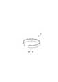
ABDリング220を、図15に示す。例示的なABDリング220は、比較的大きい直径まで半径方向外向きに付勢され、比較的小さい直径まで半径方向内向きに屈曲または圧縮するように構成されたC字形ばねである。ABDリング220は、ステンレス鋼または別の好適な材料で構成することができる。 The
ボタン230を、図16および図17に示す。例示的なボタン230は、接触面231、内側リング232、および外側リング233を含む。内側リング232は、シャトル190の凹部195と相互作用するように半径方向内向きに延在する1つ以上の内側リブ234と、図18に示される、ABDリング220の上方で半径方向外向きに延在する1つ以上の外側リブ235と、を含む。外側リング233は、図4に示されるように、上部ハウジング210のロックインジケータ213Aまたは非ロックインジケータ213Bと選択的に位置合わせするように構成されたロックインジケータ236を含む。ボタン230は、ABS、ポリカーボネート(PC)、ポリアクリレート(PA)、または別の好適な材料で構成することができる。
例示的なアクチュエータ組立体120は、以下の例示的な組み立てプロセスに従って、図18を参照して組み立てられてもよいが、これらの工程の順序は異なり得る。一度組み立てられると、デバイス100の注射器110、下部混合チャンバ150、上部混合チャンバ160、および上部ハウジング210は、協働して、デバイス100のバレル106を画定し得る。 The
まず、ABDリング220を、上部ハウジング210に取り付ける。この工程は、上部ハウジング210の内側リム211がABDリング220を半径方向内向きに圧縮するまで、ABDリング220を下向きに押すことを含み得る。圧縮されたABDリング220は、可能な限り半径方向外向きに拡張して、上部ハウジング210の内側リム211と係合することになる。 First, the
第2に、ばね170を、下部混合チャンバ150内に設置する。この工程は、ばね170を上部混合チャンバ160内に挿入し、ばね170を下方混合チャンバ150内に下向きに摺動させることを可能にすることを含み得る。 Second, the
第3に、ピストン180を、混合チャンバ150、160内に設置する。この工程は、図21に示されるように、ピストン180を下向きに強制して、ばね170を圧縮すること、およびピストン180のロックタブ183が上部混合チャンバ160上の対応するロックタブ161の下に位置合わせされるまで、ピストン180を回転させることを含み得る。回転ツール(例えば、スクリュードライバ)(図示せず)が、ピストン180の交差スロット182と係合して、ピストン180を押し下げて回転させることができる。ピストン180は、圧縮ばね170の力の下で、上方混合チャンバ160の内部ロックタブ161と係合するように上向きに付勢されてもよい。この位置において、ピストン180上の封止部181は、下部混合チャンバ150に対して封止されてもよい。 Third, the
第4に、シャトル190を、ピストン180の上方の上部混合チャンバ160内に設置する。この工程は、上部混合チャンバ160のガイドキー162がシャトル190のキー溝192を通って進む際に、シャトル190を下向きに移動させることを含み得る。より具体的には、ガイドキー162は、図19を参照して示されるように、キー溝192の下部垂直部分192Aとキー溝192の中間水平部分192Bとの間の交点に達するまで、キー溝192の下部垂直部分192Aを通って進む。この位置において、停止面193は、上部混合チャンバ160の内部ガイドキー162に当接して、シャトル190のそれ以上の下向きの移動を防止し得る。シャトル190は、圧縮ばね170の力の下で、上部混合チャンバ160に対して上向きに付勢されてもよい。 Fourth, the
第5に、下部混合チャンバ150が、第2の試薬(図示せず)を装填される。この工程は、下部混合チャンバ150内の下部孔153を通して第2の試薬を挿入することを含み得る。一例において、第2の試薬は、珪藻土粉末中の重炭酸カリウム等の重炭酸塩粉末である。他の好適な試薬は、上記のセクション2に記載されている。例示的な下部混合チャンバ150は、約200mg、250mg、300mg、またはそれ以上の第2の試薬を保持するようにサイズ決定され得るが、この量は変動し得る。この工程はまた、下部混合チャンバ150に第2の試薬を充填した後に、下部孔153を下部プラグ140で閉じることを含み得る。下部プラグ140は、下部混合チャンバ150の下部孔153に摩擦嵌合され得る。 Fifth, the
第6に、上部ハウジング210を、上部混合チャンバ160上に設置する。この工程は、上部ハウジング210のキー溝212を上部混合チャンバ160の対応する位置合わせキー163と位置合わせすることを含み得る。より具体的には、この工程は、上部ハウジング210の比較的広い第1の位置合わせキー溝212Aを上部混合チャンバ160の比較的広い第1の位置合わせキー163Aと位置合わせすること、上部ハウジング210の比較的狭い第2の位置合わせキー溝212Bを上部混合チャンバ160の比較的狭い第2の位置合わせキー163Bと位置合わせすること、および上部ハウジング210の第3の位置合わせキー溝212Cと第4の位置合わせキー溝212Dを上部混合チャンバ160の第3の位置合わせキー163Cと第4の位置合わせキー163Dと位置合わせすること、を含み得る。上部ハウジング210が位置に低下すると、第3および第4の位置合わせキー163Cおよび163D上の結合タブ164が、上部ハウジング210上で嵌り、上部ハウジング210を上部混合チャンバ160に対して定位置に保持する。 Sixth, the
第7に、シャトル190が、第1の試薬(図示せず)を装填される。この工程は、シャトル190内の上部孔194を通して第1の試薬を挿入することを含み得る。一例において、第1の試薬は、水性クエン酸である。他の好適な試薬は、上記のセクション2に記載されている。例示的なシャトル190は、約500μL、550μL、600μL、またはそれ以上の第1の試薬を保持するようにサイズ決定され得るが、この量は変動し得る。この工程はまた、上部プラグ200を上部孔194に螺合することによって等、シャトル190に第1の試薬を装填した後、上部孔194を上部プラグ200で閉じることを含み得る。 Seventh, the
第8に、ボタン230を、シャトル190に設置する。この工程は、ボタン230の内側リブ234をシャトル190の外側凹部195と位置合わせして、ボタン230とシャトル190を共に回転可能にロックすることを含み得る。この位置において、ボタン230上のインジケータ236は、図3に示されるように、上部ハウジング210上のロックインジケータ213Aと位置合わせし得る。ボタン230は、シャトル190内の上部孔194および上部プラグ200を隠すことを援助し得る。ボタン230はまた、シャトル190と共に回転するように摩擦嵌合、超音波溶接、または他の方法でシャトル190に結合されてもよい。 Eighth, the
最後に、注射器110が、アダプタ130を用いてアクチュエータ組立体120に結合され得る。この接続は、上記でさらに説明されている。 Finally, the
最初に、デバイス100は、図2および図18に示されるように、ピストン180が下向きに保持されて、ばね170を圧縮する、装填かつロック構成で提供され得る。この装填かつロック構成において、デバイス100のバレル106は、複数のチャンバ、例示的には第1の作動チャンバ300、第2の反応チャンバ302、および第3の治療用流体チャンバ304に分割され得る。第1の作動チャンバ300は、ピストン180の上方の上部混合チャンバ160およびシャトル190内に位置付けられ、第1の試薬(例えば、クエン酸水溶液)を含有する。第2の反応チャンバ302は、ピストン180の下の下部混合チャンバ150内に位置付けられ、第2の試薬(例えば、重炭酸カリウム)を含有する。第3の治療用流体チャンバ304は、プランジャ116の下の注射器110内に位置付けられ、治療用流体を含有する。これら3つのチャンバ300、302、および304は、同軸であり、各々が円筒形状を有するように図示される。デバイス100は、この装填かつロック構成で格納されてもよい。 First, the
デバイス100の使用準備が整ったとき、デバイス100を、ロック構成から非ロック構成に移動させることができる。この工程は、上部ハウジング210に対してボタン230を回転させることを含み得る。ボタン230上のインジケータ236は、図3に示されるように、上部ハウジング210上のロックインジケータ213Aから離れて、上部ハウジング210上の非ロックインジケータ213Bと位置合わせするように移動することができる。 When the
ボタン230の回転は、例示的にはボタン230上の内側リブ234とシャトル190上の外側凹部195との間の係合を介して、シャトル190の回転をもたらす。この回転中、上部混合チャンバ160のガイドキー162は、図19〜図21に示されるように、シャトル190のキー溝192を通って進み続ける。より具体的には、ガイドキー162は、キー溝192の中間水平部分192Bと上部垂直部分192Cとの間の交点に達するまで、キー溝192の中間水平部分192Bを通って進む。 The rotation of the
図22に示されるように、非ロック構成から、デバイス100は、治療用流体を患者に送達するために、非装填または送達構成に移動され得る。この工程は、上部ハウジング210に対して下向きにボタン230の接触面231を押すことを含み得る。 As shown in FIG. 22, from the unlocked configuration, the
ボタン230の下向き移動は、上部混合チャンバ160に対するシャトル190の下向き移動を引き起こす。ボタン230およびシャトル190は共に動作するので、2つの構成要素は、まとめてアクチュエータとして呼ぶことができる。シャトル190のこの下向き移動中、上部混合チャンバ160のガイドキー162は、図19〜図21に示されるように、シャトル190のキー溝192を通って進み続ける。より具体的には、ガイドキー162は、キー溝192の上部垂直部分192Cを通って進む。 The downward movement of the
付加的に、ボタン230、具体的にはボタン230の外側リブ235の下向き移動は、ABDリング220の下向き移動を引き起こす。ABDリング220が上部ハウジング210の内側リム211を通過して移動すると、ABDリング220は、図22に示されるように、上部混合チャンバ160に半径方向外向きに自由に拡張する。拡張されたABDリング220は、上部混合チャンバ160の上部リップ165の下に捕捉される。拡張されたABDリング220は、ボタン230および上部リップ165を通過するシャトル190の上向き移動を阻止し、送達構成においてボタン230およびシャトル190を下向きに保持することによって、ロック機構として機能し得、それによりボタン230およびシャトル190が、初期の装填構成へと上向きに戻ることを防止する。送達構成においてボタン230およびシャトル190を下向きに保持することは、バレル106内部の容積が送達プロセスを通して一貫したままであることを確実にする。また、送達構成においてボタン230およびシャトル190を下向きに保持することによって、ユーザが、デバイス100が使用されていることを視覚的に検出することが可能になる。 Additionally, the downward movement of the
シャトル190の下向き移動は、ピストン180の回転を引き起こす。図23に示されるように、シャトル190の傾斜面196は、ピストン180の対応する傾斜面185と係合して、ピストン180の回転を駆動する。図24に示されるように、ピストン180が回転する際、ピストン180の回転タブ184がシャトル190の下から解放され、ピストン180のロックタブ183が上部混合チャンバ160のロックタブ161の下から解放される。 The downward movement of the
図22に示されるように、解放されたピストン180は、ばね170がその圧縮状態からその中立または解放状態に移行するにつれて、上向きに移動してシャトル190に入る。この移行中、ばね170は、ピストン180の上方の空気を圧縮し、封止部181と下部混合チャンバ150との間の摩擦力を克服するのに十分な力を及ぼすことになる。ばね170によって及ぼされる力は、例えば、約2.5ポンドf、3.0ポンドf、3.5ポンドf、4.0ポンドf、4.5ポンドf、またはそれ以上であってもよい。特定の一例において、ばね170は、ピストン180の上方の空気を圧縮するために約2.0ポンドf、封止部181と下部混合チャンバ150との間の摩擦力を克服するために約0.9ポンドfを及ぼす必要があり、そのためばね170は、3.6ポンドf等、少なくとも約2.9ポンドfを及ぼすように設計されるべきである。As shown in FIG. 22, the released
ピストン180の上向き移動は、それらの間の封止されたインターフェースを破壊することによって作動チャンバ300を反応チャンバ302と連通させる。例解された実施形態において、シャトル190は、下部混合チャンバ150よりもわずかに大きい内径を有し、そのためピストン180上の封止部181は、図18の装填構成においては下部混合チャンバ150に抗して封止するが、図22の送達構成においてはシャトル190に抗する封止をしない。ピストン180は、封止されたインターフェースが破壊される前に短い距離だけ進む必要があり得、それはピストン180の上部の最小のヘッドスペースを可能にする。作動チャンバ300からの第1の試薬は、反応チャンバ302内の第2の試薬に曝され、そしてこの曝射はデバイス100の内部でガス発生化学反応を引き起こす。封止部181とシャトル190との間の空間は、試薬が互いに曝される速度を制御するために変えることができる。例えば、シャトル190の内面は、1つ以上の流体送達チャネル198(図22および図23)を含み、第1の試薬が作動チャンバ300から、ピストン180を通過して、反応チャンバ302内に流れるのを促進することができる。ピストン180上の1つ以上の交差スロット182は、送達構成において流体送達チャネル198と位置合わせするように回転して、ピストン180を横切る流体の流れをさらに方向付けることができる。 The upward movement of the
発生したガスは、デバイス100内の圧力を上昇させる。ボタン230は、送達構成において下向きに保持され、初期装填構成に上向きに戻ることが防止されるので、バレル106内部の容積は、送達プロセスを通して一定のままであり、バレル106内部の圧力は、デバイス100から下向きに逃げることを強いられる。閾値圧力がデバイス100の内部に到達し、対応する閾力が下部プラグ140に適用されると、下部プラグ140は、図2の送達前位置、すなわち装填位置から、下部孔153からプランジャ116に向かう送達位置まで、下向きに強いられ得る。下部プラグ140の下向き移動は、プランジャ116を注射器110を通して下向きに押し、プランジャ116の下向き移動は、患者への送達のために、治療用流体を針117を通して治療用流体チャンバ304から押し出す。下部プラグ140上の閾力は、例えば、約0.1ポンドf、0.2ポンドf、0.3ポンドf、0.4ポンドf、0.5ポンドf、またはそれ以上であり得る。デバイス100は、治療用流体を患者に迅速に送達するためにこの閾力に素早く達することができる。反応が続くにつれて、デバイス100内の圧力は、閾値圧力を超えて著しく増加することがある。例えば、デバイス100内の圧力は、約200psi、300psi、400psi、500psi、またはそれ以上に達する場合がある。The generated gas raises the pressure in the
デバイス100は、デバイス100が送達構成において使用されたとき、ユーザに視覚的に示すように構成され得る。この可視表示の一例は、上述のように、ボタン230の下向きのロックである。別の例は、デバイス100内の下部プラグ140および/またはプランジャ116の可視位置である。一実施形態において、デバイス100は、1つ以上の窓(図示せず)を含み、それを通してユーザは、下部プラグ140および/またはプランジャ116が図2の送達前位置もしくは装填位置にあるか、最終送達位置にあるかを見ることができる。ラベル(図示せず)は、窓に隣接して提供されて、下部プラグ140および/またはプランジャ116の位置をユーザにさらに伝えることができる。さらに別の例は、反応チャンバ302内の可視圧力インジケータである。一実施形態において、デバイス100は、1つ以上の窓(図示せず)を含み、それを通してユーザが、生成されたガスで満たされ、使用中に膨張する反応チャンバ302内のバルーン(図示せず)を見ることができる。 The
例示的な実施形態において、封止部115、181、191は、デバイス100の内部の圧力および反応状態に耐えることができる。封止部115、181、191のための例示的な材料としては、ブチルゴム、およびフルオロエラストマー(例えば、The Chemours Company社から入手可能なViton(登録商標))が挙げられる。 In an exemplary embodiment, the
図25および図26は、デバイス100(図2)と共に使用するための修正版アクチュエータ組立体120を示し、エラストマ下部プラグ140が取り外し可能な下部キャップ240と交換される。アクチュエータ組立体120が注射器110(図2)に結合される前に、下部キャップ240を下部混合チャンバ150に結合して、下部孔153を閉じ、第2の試薬を下部混合チャンバ150内に保持することができる。アクチュエータ組立体120が注射器110に結合される準備ができたとき、下部キャップ240は、下部混合チャンバ150から取り外すことができる。一実施形態において、下部キャップ240を取り外した状態で試薬を保持するのを助けるために、フィルタ(例えば、図33のフィルタ402)が下部孔153内に配置される。発生したガスは、下部プラグ140ではなく、プランジャ116(図2)を移動させるだけでよいので、修正されたデバイス100は、より低い圧力要件を有してもよい。 25 and 26 show a modified
4.第2の送達デバイス
図27は、本開示の第2の例示的な送達デバイスのアクチュエータ組立体120’を示す。第2の例示的な送達デバイスのアクチュエータ組立体120’は、デバイス100のアクチュエータ組立体120と同様であり、以下に説明されることを除いて、同じ参照番号は同じ部品を示す。アクチュエータ組立体120のように、アクチュエータ組立体120’は、注射器(例えば、図2の注射器110)、自動注入ペン、または別の好適な送達デバイスに結合されてもよい。アクチュエータ組立体120’の以下の構成要素は、図27に示されている、下部混合チャンバ150’、上部混合チャンバ160’、らせん状ばね170’、ピストン180’、シャトル190’、および上部プラグまたはネジ200’である。アクチュエータ組立体120’は、(デバイス100の下部プラグ140と同様の)下部プラグ、(デバイス100の下部キャップ240と同様の)下部キャップ、および/または(ボタン230と同様の)アクチュエータノブ等の、図に示されていない付加的な構成要素を含み得る。4. Second Delivery Device FIG. 27 shows the actuator assembly 120'of the second exemplary delivery device of the present disclosure. The actuator assembly 120'of the second exemplary delivery device is similar to the
例示的な下部混合チャンバ150’および上部混合チャンバ160’は、単一のユニットとして一体的に共に形成される。その下端において、混合チャンバ150’、160’は、(デバイス100のアダプタ130と同様に)アダプタに結合するために外側に螺合される。その上端で、混合チャンバ150’、160’は、1つ以上のロック表示窓166’を画定する。混合チャンバ150’、160’は、積層された配置におけるばね170’、ピストン180’、およびシャトル190’を受容するようにサイズ決定される。 The exemplary lower mixing chamber 150'and upper mixing chamber 160' are integrally formed together as a single unit. At its lower end, the mixing chambers 150', 160' are screwed outward to connect to the adapter (similar to the
例示的なピストン180’は、シャトル190’と相互作用するように半径方向外向きに延在する1つ以上のロックタブ183’を含む。より具体的には、例示的なピストン180’は、ピストン180’の周囲に互いに45度離れて配置された8つのロックタブ183’を含む。 An exemplary piston 180'includes one or more lock tabs 183' that extend radially outward to interact with the shuttle 190'. More specifically, the exemplary piston 180'includes eight lock tabs 183' located 45 degrees apart from each other around the piston 180'.
例示的なシャトル190’は、図29に示されるように、ピストン180’と相互作用するように半径方向内向きに延在する1つ以上のロックタブ197’を含む。より具体的には、例示的なシャトル190’は、シャトル190’の周囲に互いに45度離れて配置された8つのロックタブ197’を含む。シャトル190’はまた、隣接するロックタブ197’の間にチャネル198’を含む。その上端で、シャトル190’は、1つ以上の二重目的ロックインジケータタブ199’を含み、混合チャンバ150’、160’に対するシャトル190’の位置を制御し、かつ伝達の両方をする。 An exemplary shuttle 190'includes one or more lock tabs 197' that extend radially inward to interact with piston 180', as shown in FIG. More specifically, the exemplary shuttle 190'includes eight lock tabs 197' located 45 degrees apart from each other around the shuttle 190'. Shuttle 190'also includes channel 198'between adjacent lock tabs 197'. At its upper end, the shuttle 190'contains one or more dual purpose lock indicator tabs 199', which controls the position of the shuttle 190'with respect to the mixing chambers 150', 160' and provides both transmission.
例示的なアクチュエータ組立体120’は、混合チャンバ150’、160’内にばね170’、ピストン180’およびシャトル190’を設置することによって組み立てることができる。シャトル190’が混合チャンバ150’、160’に対して下向きに移動する際、ロックインジケータタブ199’は、内向きに撓み、次いでシャトル190’を混合チャンバ150’、160’内に保持するためにロックインジケータ窓166’に外向きに嵌める。 An exemplary actuator assembly 120'can be assembled by installing springs 170', pistons 180' and shuttle 190'in mixing chambers 150', 160'. As the shuttle 190'move downwards relative to the mixing chambers 150', 160', the lock indicator tab 199'bends inward and then holds the shuttle 190'into the mixing chambers 150', 160'. Fit outward into the lock indicator window 166'.
組み立てられたアクチュエータ組立体120’は、図28および図29に示されるように、装填かつロック構成を有して、ピストン180’が下向きに保持されて、ばね170’を圧縮し得る。ピストン180’は、ピストン180’のロックタブ183’をシャトル190’のロックタブ197’の下に位置合わせすることによって、この位置に保持され得る。シャトル190’のロックインジケータタブ199’は、混合チャンバ150’、160’のロックインジケータ窓166’を通してロック位置(例えば、左向きの位置)に視認可能である。 The assembled actuator assembly 120'has a loading and locking configuration, as shown in FIGS. 28 and 29, with the piston 180'holding downwards to compress the spring 170'. The piston 180'can be held in this position by aligning the lock tab 183'of the piston 180' under the lock tab 197' of the shuttle 190'. The lock indicator tab 199'of the shuttle 190' is visible in the lock position (eg, leftward position) through the lock indicator window 166' of the mixing chambers 150', 160'.
図30および図31に示されるように、アクチュエータ組立体120’を、ロック構成から、送達構成に移動させることができる。この工程は、シャトル190’のロックタブ197’がピストン180’のロックタブ183’からオフセットされ、シャトル190’のチャネル198’がピストン180’のロックタブ183’と位置合わせされるまで、混合チャンバ150’、160’に対してシャトル190’を回転させることを含み得る。ロックタブ183’、197’のサイズおよび位置に応じて、シャトル190’の必要な回転は、約25度、20度、15度、10度以下等、小さくてもよい。この回転中、シャトル190’のロックインジケータタブ199’は、混合チャンバ150’、160’のロックインジケータ窓166’内の非ロック位置(例えば、右向きの位置)に移動する。 As shown in FIGS. 30 and 31, the actuator assembly 120'can be moved from the lock configuration to the delivery configuration. In this step, the mixing chamber 150', until the lock tab 197' of the shuttle 190' is offset from the lock tab 183' of the piston 180' and the channel 198' of the shuttle 190' is aligned with the lock tab 183' of the piston 180', It may include rotating the shuttle 190'with respect to 160'. Depending on the size and position of the lock tabs 183'and 197', the required rotation of the shuttle 190'may be as small as about 25 degrees, 20 degrees, 15 degrees, 10 degrees or less. During this rotation, the lock indicator tab 199'of the shuttle 190'move to an unlocked position (eg, to the right) within the lock indicator window 166' of the mixing chambers 150', 160'.
ばね170’がその圧縮状態からその中立または解放状態に移行するにつれて、解放されたピストン180’は、シャトル190’に上向きに移動する。より具体的には、ピストン180’の係止タブ183’は、シャトル190’のチャネル198’を通って上向きに移動する。ピストン180’の上向き移動は、ピストン180’の両側の封止されたインターフェースを破壊し、ピストン180’を横切る流体連通を可能にする。シャトル190’のチャネル198’は、この実施形態において二重の目的を果たすことができる。ピストン180’のロックタブ183’を上向きに案内することに加えて、シャトル190’のチャネル198’は、ピストン180’を横切って下向きに流れる流体を案内することができる。このため、チャネル198’のサイズは、制御されて、ピストン180’を横切る流体の流れおよび混合の速度を制御することができる。ピストン180’はまた、流体の流れをさらに方向付けるために、図10のピストン180のスロット182と同様に、その外面上にチャネルを含んでもよい。ピストン180’は、封止部が破壊される前に短い距離だけ進む必要があり得、ピストン180’の上部の最小のヘッドスペースを可能にする。破壊された封止部は、デバイス100に関して上述されたように、第2の例示的な送達デバイスのアクチュエータ組立体120’の内部でガス発生化学反応を引き起こす。 As the spring 170'shifts from its compressed state to its neutral or released state, the released piston 180'move upwards to the shuttle 190'. More specifically, the locking tab 183'of the piston 180' moves upward through channel 198' of the shuttle 190'. The upward movement of the piston 180'breaks the sealed interfaces on either side of the piston 180' and allows fluid communication across the piston 180'. Channel 198'of shuttle 190'can serve a dual purpose in this embodiment. In addition to guiding the lock tab 183'of piston 180'upward, channel 198' of shuttle 190'can guide fluid flowing downward across piston 180'. Therefore, the size of channel 198'can be controlled to control the flow of fluid and the rate of mixing across piston 180'. Piston 180'may also include channels on its outer surface, similar to slot 182 of
5.第3の送達デバイス
図32は、本開示の第3の例示的な送達デバイス100”を示す。デバイス100”は、デバイス100と同様であり、以下に説明されることを除いて、同じ参照番号は同じ部品を示す。デバイス100”は、注射器110”、自動注入ペン、または別の好適な送達デバイスを含み得る。アクチュエータ組立体120”の以下の構成要素が図32に示され、作動チャンバ300”および反応チャンバ302”を有するバレル106”、一方向バルブ380”(例えば、チェックバルブ、アンブレラバルブ)、ステム392”を有するプランジャ390”、ばね170”、およびボタン230”を有する。アクチュエータ組立体120”は、(デバイス100の下部プラグ140と同様の)下部プラグ、または(デバイス100の下部キャップ240と同様の)下部キャップ等、図に示されていない付加的な構成要素を含み得る。5. Third Delivery Device FIG. 32 shows a third
デバイス100”は、装填かつロック構成を有し、一方向バルブ380”が作動チャンバ300”内の第1の試薬(例えば、水性クエン酸)を反応チャンバ302”内の第2の試薬(例えば、重炭酸カリウム)から分離することができる。ボタン230”は、ばね170”の力を受けてバレル106”に対して上向きに付勢されてもよい。ボタン230”はまた、プランジャ390”のステム392”との物理的干渉により、バレル106”に対して下方に移動することが防止されてもよい。 The
デバイス100”の使用準備が整ったとき、デバイス100”を、ロック構成から非ロック構成に移動させることができる。この工程は、ステム392”に対してボタン230”を回転させることを含み、ステム392”に対する以前の干渉を排除することができる。この非ロック構成において、ボタン230”は、図32に示されるように、バレル106”に対して下向きに自由に移動し得る。 When the
ロック構成から、デバイス100”を送達構成に移動させることができる。この工程は、ボタン230”をバレル106”に対して下向きに押すことを含み得る。まず、ステム392”は、バレル106”と摩擦係合し、そのためボタン230”の下向き移動がばね170”を圧縮し得る。圧縮ばね170”内に蓄えられたエネルギーが、ステム392”とバレル106”との間の摩擦係合を克服するのに十分であるとき、ばね170”は、プランジャ390”を解放し、バレル106”に対して下向きに駆動することができる。有利には、ばね170”は、プランジャ390”の速く、一定した移動を促進することができる。 From the lock configuration, the
プランジャ390”の下向き移動は、第1の試薬を作動チャンバ300”から押し出す。ばね170”はプランジャ390”の速く、一定した移動を促進することができるので、ばね170”もまた、第1の試薬の速く、一定した送達を促進し得る。第1の試薬は、一方向バルブ380”を横切って反応チャンバ302”に進み、反応チャンバ302”内に既に存在する第2の試薬と混合することができる。この混合は、デバイス100に対して上述したように、反応チャンバ302”内でガス発生化学反応を引き起こす。反応チャンバ302”内の圧力は、一方向バルブ380”を閉じることができ、それによって、発生したガスおよび他の材料が作動チャンバ300”に上向き(すなわち、逆流)に逃げることを防止する。 The downward movement of the
6.液体吸収
デバイス100に関して上述されたように、液体試薬は、送達前または装填構成(図33)内で作動チャンバ300内に蓄えられ得、送達構成(図34)内で反応チャンバ302に進むことができ、液体試薬は、乾燥試薬と混合して反応する。送達構成(図34)において反応チャンバ302内に存在する液体は、作動チャンバ300からの任意の未反応液体試薬および/または反応チャンバ302内の化学反応中に生成された任意の液体の混合物であり得る。混合物はまた、乾燥試薬等の溶解固体、および/または反応チャンバ302内の化学反応中に生成される任意の固体を含有し得る。ある実施形態において、混合物は、水を含有してもよく、それ自体、水性混合物と見なされてもよい。6. As mentioned above for the
デバイス100、または上述の他のデバイスのいずれかは、1つ以上の液体吸収剤(図示せず)を含んで、送達構成(図34)において反応チャンバ302内に存在する混合物から過剰の液体を吸収することができる。ある実施形態において、吸収剤(複数可)は、送達構成(図34)において反応チャンバ302内に存在する液体の大部分を吸収することができる。反応チャンバ302内の吸収剤(複数可)の比、場所、および特性に基づいて、吸収は、液体が治療用流体チャンバ304に入ることを防止しながら、反応チャンバ302内の化学反応干渉する(例えば、遅くする)ことを回避するように制御されてもよい。
第1の例示的な吸収剤は、超吸収性ポリマー(SAP)粉末(例えば、ヒドロゲル)等の吸収性粉末400(図33および図34)である。吸収性粉末400は、その吸収速度および吸収能力、長期安定性、価格、反応物およびデバイス材料との化学的適合性、加圧下での液体保持性、ならびに化学的安全性に基づいて選択することができる。吸収速度は、吸収性粉末400の粒径を変えることによって制御することができる。例えば、吸収性粉末400の粒径範囲は、150ミクロン以下、250ミクロン以下、または他の好適な範囲であり得る。例示的な吸収性粉末400は、光架橋を有するポリ(アクリル酸)ナトリウム塩(すなわち、ポリアクリル酸ナトリウム)、または光架橋を有するポリ(アクリル酸)カリウム塩(すなわち、ポリアクリル酸カリウム)などの他の好適な塩である。塩の吸収特性は、架橋の量に対応し得る。 The first exemplary absorbent is an absorbent powder 400 (FIGS. 33 and 34) such as a superabsorbent polymer (SAP) powder (eg, hydrogel). Absorbable powder 400 should be selected based on its absorption rate and capacity, long-term stability, price, chemical compatibility with reactants and device materials, liquid retention under pressure, and chemical safety. Can be done. The absorption rate can be controlled by changing the particle size of the absorbent powder 400. For example, the particle size range of the absorbent powder 400 can be 150 microns or less, 250 microns or less, or other suitable range. The exemplary absorbent powder 400 includes a poly (acrylic acid) sodium salt having photocrosslinking (ie, sodium polyacrylate), a poly (acrylic acid) potassium salt having photocrosslinking (ie, potassium polyacrylate), and the like. Other suitable salts. The absorption properties of the salt can correspond to the amount of cross-linking.
初期の装填構成において、吸収性粉末400は、乾燥試薬と混合され得る。図33に示されるように、吸収性粉末400は、反応チャンバ302内で第2の試薬(例えば、重炭酸カリウム)と混合される。 In the initial loading configuration, the absorbent powder 400 can be mixed with the desiccant. As shown in FIG. 33, the absorbent powder 400 is mixed with a second reagent (eg, potassium bicarbonate) in the
送達構成において、液体試薬が乾燥試薬と混合して反応すると、吸収性粉末400は、液体混合物から過剰な液体を吸収して膨潤することがある。図34に示されるように、第1の試薬(例えば、クエン酸水溶液)が作動チャンバ300を出て、反応チャンバ302内の第2の試薬と混合かつ反応した後、吸収性粉末400は、反応チャンバ302内の液体混合物から過剰な液体を吸収し得る。例えば、吸収性粉末400は、反応チャンバ302内に存在する過剰な液体試薬および/または液体生成物を吸収することがある。 In the delivery configuration, when the liquid reagent mixes with the drying reagent and reacts, the absorbent powder 400 may absorb excess liquid from the liquid mixture and swell. As shown in FIG. 34, after the first reagent (eg, aqueous citric acid solution) exits the working
吸収性粉末400に加えて、または代替的に、粘度調整剤ポリマーが、提供されて、溶解させ、それによって水性反応混合物の粘度を増大させることができる。例示的な粘度調整剤は、例えば、ポリ(エチレンオキシド)、キサンタンガム、およびポリ(エチレングリコール)メチルエーテルを含む。かかる材料(例えば、粉末)は、溶解を通して反応チャンバ302内の水性混合物の粘度を変更することがあり、そのため液体が治療用流体チャンバ304に流れ込むには粘性が高くなりすぎる。 In addition to or as an alternative to the absorbent powder 400, a viscosity modifier polymer can be provided and dissolved, thereby increasing the viscosity of the aqueous reaction mixture. Exemplary viscosity modifiers include, for example, poly (ethylene oxide), xanthan gum, and poly (ethylene glycol) methyl ether. Such materials (eg, powders) may change the viscosity of the aqueous mixture in the
第2の例示的な吸収剤は、ガス透過性の親水性フィルタ402である。フィルタ402は、実質的に反応チャンバ302と治療用流体チャンバ304との間(すなわち、反応チャンバ302の下流側かつ治療用流体チャンバ304の上流側)に配置されてもよい。図33に示されるように、初期の装填構成において、フィルタ402は、反応チャンバ302内に第2の試薬(例えば、重炭酸カリウム)を収容することを援助し得る。図34に示されるように、送達構成において、フィルタ402は、治療用流体チャンバ304に入ろうとするいずれの液体を吸収することができる。例えば、フィルタ402は、治療用流体チャンバ304に入ろうとするいずれの液体試薬および/または液体製品を吸収することができる。フィルタ402はまた、治療用流体チャンバ304に入ろうとするいずれの固体または粒子を遮断し得る。フィルタ402は、上述のように、反応チャンバ302内の生成ガスを注射器110のプランジャ116に向かって通過させて、治療用流体チャンバ304から治療用流体を送達することを可能にするように適合される。例示的なフィルタ402は、ランダムに配向された繊維を有する未使用の綿から形成される。一実施形態において、綿は、円筒形または他の好適な形状に巻かれ、組み立て中に反応チャンバ302の出口に圧入される。他の例示的なフィルタ402は、天然繊維、スポンジ、セルロース(例えば、結合セルロースアセテート)、吸収性布(例えば、ShamWOW(登録商標)布)、および発泡体から形成される。必要であれば、フィルタ402を定位置に保持するためにハウジング(図示せず)を設けることができる。ハウジングは、デバイス100の下部プラグ140(図5)のシャフト142と同様に、反応チャンバ302の出口に摩擦嵌合する成形プラグを含み得る。一実施形態において、下部キャップ240(図25)は、アクチュエータ組立体120を注射器110または他の送達デバイスに取り付ける前に、貯蔵のために出口収容フィルタ402を覆って結合される。 A second exemplary absorbent is a gas permeable
吸収性粉末400(および/または粘度調整剤粉末)およびフィルタ402は、単独でまたは組み合わせて使用することができる。吸収性粉末400をフィルタ402全体に分配することによって、または吸収性粉末400をフィルタ402の凹部内に配置することによって等、吸収性粉末400をフィルタ402と物理的に組み合わせることも本開示の範囲内である。一実施形態において、吸収性粉末400(および/または粘度調整剤)は、フィルタ402内、反応チャンバ302内の両方において第2の試薬を伴い提供される。 The absorbent powder 400 (and / or viscosity modifier powder) and filter 402 can be used alone or in combination. It is also within the scope of the present disclosure to physically combine the absorbent powder 400 with the
デバイス100、デバイス100’、および/またはデバイス100”は、米国特許第9,321,581号、表題「Process and Device for Delivery of Fluid by Chemical Reaction」において開示された他の特徴を有してもよく、その開示内容は、その全体が参照により本明細書に明示的に組み込まれる。 The
本発明は例示の設計を有するものとして記載されてきたが、本発明は、本開示の趣旨および範囲内でさらに修正されてもよい。したがって、本出願は、本発明の一般的原理を用いた本発明の任意の変形、使用、または適応を包含することが意図される。さらに、本出願は、本発明が関係し、添付の特許請求の範囲の限定の範囲内に入る、当該技術分野で既知のまたは慣習的な実施の範囲内に入るものとして、本開示からのそのような逸脱を網羅することを意図する。
なお、本発明には、以下の態様が含まれることを付記する。
〔態様1〕
化学反応によって治療用流体を送達するためのデバイスであって、前記デバイスが、
第1のチャンバ、第2のチャンバ、および第3のチャンバを有するバレルと、
前記バレルの前記第1のチャンバと前記第2のチャンバとの間に配置されたピストンと、
前記ピストンを移動させるように構成されたばねと、
前記バレルの前記第2のチャンバと前記第3のチャンバとの間に配置されたプランジャと、
アクチュエータであって、
前記アクチュエータが前記バレルに対して軸方向に移動することが防止されるロック構成と、
前記アクチュエータが前記バレルに対して軸方向に移動可能である非ロック構成と、
前記アクチュエータが前記バレルに対して軸方向に移動する送達構成と
を有する前記アクチュエータと
を備え、
前記ロック構成および前記非ロック構成において、前記第1のチャンバが第1の試薬を収容し、前記第2のチャンバが第2の試薬を収容し且つ前記ピストンによって前記第1のチャンバから分離され、前記第3のチャンバが前記治療用流体を収容し、
前記送達構成において、前記第1のチャンバを前記第2のチャンバと連通させるように前記ばねは前記ピストンを移動させ、前記第1の試薬および前記第2の試薬は反応し、前記治療用流体を前記第3のチャンバから送達するように前記プランジャを駆動するガスを発生する、前記デバイス。
〔態様2〕
前記アクチュエータが、前記ロック構成と前記非ロック構成との間で前記バレルに対して回転される、態様1に記載のデバイス。
〔態様3〕
前記アクチュエータが、
前記バレル内に受容されたシャトルと、
前記バレルに結合されたボタンと
をさらに備える、態様1に記載のデバイス。
〔態様4〕
前記シャトルが、前記第1の試薬を受容するように構成されたポートを含み、前記ボタンが、前記シャトル内の前記ポートを覆っている、態様3に記載のデバイス。
〔態様5〕
前記シャトルが、キー溝を含み、前記バレルが、前記シャトルの前記キー溝と相互作用するように半径方向内向きに延在するキーを含む、態様3に記載のデバイス。
〔態様6〕
前記シャトルの前記キー溝が、水平部分および垂直部分を有し、前記バレルの前記キーが前記ロック構成と前記非ロック構成との間で前記キー溝の前記水平部分を通って且つ前記非ロック構成と前記送達構成との間で前記キー溝の前記垂直部分を通って進む、態様5に記載のデバイス。
〔態様7〕
前記バレルの前記キーが、前記ロック構成において前記シャトルの停止面に当接する、態様5に記載のデバイス。
〔態様8〕
前記バレルが、
上部ハウジングと、
前記上部ハウジングに結合され、内側肩部を有するアダプタと、
前記アダプタの前記内側肩部上に載置されるように構成された上部リムを有する注射器と
を備える、態様1に記載のデバイス。
〔態様9〕
前記ピストンが、
前記ロック構成および前記非ロック構成において前記バレルと相互作用する少なくとも1つのロックタブと、
前記送達構成において前記アクチュエータと相互作用する少なくとも1つの傾斜回転タブと
を備える、態様1に記載のデバイス。
〔態様10〕
前記少なくとも1つの傾斜回転タブが、隣接するロックタブ間で周囲方向に配置されている、態様9に記載のデバイス。
〔態様11〕
前記アクチュエータが前記非ロック構成に上向きに戻ることを防止するために、前記送達構成において、前記アクチュエータを前記バレルに対して下向きに保持するC字形リングをさらに備える、態様1に記載のデバイス。
〔態様12〕
前記ピストンと前記プランジャとの間で前記バレルに結合されたプラグをさらに備え、前記プラグは、前記ロック構成および前記非ロック構成において前記第2のチャンバを封止し、前記送達構成において前記第2のチャンバを開く、態様1に記載のデバイス。
〔態様13〕
液体が前記第3のチャンバに達する前に、前記第2のチャンバ内の前記液体を吸収するように構成された少なくとも1つの吸収剤をさらに含み、前記液体は、前記第1の試薬と、前記第1の試薬及び前記第2の試薬の化学反応の間に生じる液体とを含む、態様1に記載のデバイス。
〔態様14〕
前記少なくとも1つの吸収剤が、超吸収性ポリマーである、態様13に記載のデバイス。
〔態様15〕
前記超吸収性ポリマーが、前記第2のチャンバ内で第2の試薬と混合される、態様14に記載のデバイス。
〔態様16〕
前記少なくとも1つの吸収剤が、前記第3のチャンバの上流に配置されたガス透過性フィルタである、態様13に記載のデバイス。
〔態様17〕
化学反応によって治療用流体を送達するためのデバイスであって、
第1のチャンバ、第2のチャンバ、および第3のチャンバを有するバレルと、
前記バレルの前記第1のチャンバと前記第2のチャンバとの間に配置されたピストンと、
前記ピストンを移動させるように構成されたばねと、
前記バレルの前記第2のチャンバと前記第3のチャンバとの間に配置されたプランジャと、
第1の構成と第2の構成との間で前記バレルに対して回転するように構成されたアクチュエータと
を備え、
前記第1の構成において、前記第1のチャンバが第1の試薬を収容し、前記第2のチャンバが第2の試薬を収容し且つ前記ピストンによって前記第1のチャンバから分離され、前記第3のチャンバが前記治療用流体を収容し、
前記第2の構成において、前記第1のチャンバを前記第2のチャンバと連通させるように前記ばねは前記ピストンを移動させ、前記第1の試薬および前記第2の試薬は反応し、
前記治療用流体を前記第3のチャンバから送達するように前記プランジャを駆動するガスを発生する、前記デバイス。
〔態様18〕
前記ピストンが、半径方向外向きに延在する少なくとも1つのロックタブを含み、
前記アクチュエータが、半径方向内向きに延在する少なくとも1つのロックタブを含み、
前記ピストンの前記少なくとも1つのロックタブが、前記第1の構成において前記アクチュエータの前記少なくとも1つのロックタブの下に位置合わせされ、前記第2の構成において前記アクチュエータの前記少なくとも1つのロックタブからオフセットされている、態様17に記載のデバイス。
〔態様19〕
前記アクチュエータが、複数のロックタブと、前記ロックタブ間の複数のチャネルとをさらに含み、
前記第2の構成において、前記ピストンが、前記チャネルを通って上向きに進み、前記第1の試薬が、前記チャネルを通って下向きに進む、態様18に記載のデバイス。
〔態様20〕
前記アクチュエータが、複数のロックタブと、前記ロックタブ間の複数のチャネルとをさらに含み、前記第2の構成において、前記ピストンが、前記チャネルを通って上向きに進み、前記第1の試薬が、前記ピストンの周囲を進む、態様18に記載のデバイス。
〔態様21〕
前記バレルが、ロックインジケータ窓を含み、前記アクチュエータが、前記ロックインジケータ窓を通してユーザに視認可能なロックインジケータタブを含み、前記ロックインジケータタブが、前記ロックインジケータ窓を通って、前記第1の構成内の第1の位置から前記第2の構成内の第2の位置に並進する、態様17に記載のデバイス。
〔態様22〕
前記アクチュエータを前記バレル内に保持するように、前記ロックインジケータタブが、前記ロックインジケータ窓に嵌る、態様21に記載のデバイス。
〔態様23〕
前記ピストンが、前記第2の構成において、軸方向上向きに、かつ前記アクチュエータに向かって進む、態様17に記載のデバイス。
〔態様24〕
液体が前記第3のチャンバに達する前に、前記第2のチャンバ内の前記液体を吸収するように構成された少なくとも1つの吸収剤をさらに含み、前記液体は、前記第1の試薬と、前記第1の試薬及び前記第2の試薬の化学反応の間に生じる液体とを含む、態様17に記載のデバイス。
〔態様25〕
前記少なくとも1つの吸収剤が、超吸収性ポリマーである、態様24に記載のデバイス。
〔態様26〕
前記超吸収性ポリマーが、前記第2のチャンバ内で前記第2の試薬と混合される、態様25に記載のデバイス。
〔態様27〕
前記少なくとも1つの吸収剤が、前記第3のチャンバの上流に配置されたガス透過性フィルタである、態様24に記載のデバイス。
〔態様28〕
前記アクチュエータが、前記第1の構成と前記第2の構成との間で非ロック構成を有し、前記アクチュエータが、前記第1の構成から前記非ロック構成に、前記バレルに対して回転するように構成され、前記非ロック構成から前記第2の構成に、前記バレルに対して軸方向に移動するように構成されている、態様17に記載のデバイス。
〔態様29〕
化学反応によって治療用流体を送達するためのデバイスであって、
第1の試薬を収容する第1のチャンバ、第2の試薬および吸収性粉末を収容する第2のチャンバ、および前記治療用流体を収容する第3のチャンバを有するバレルと、
前記バレルの前記第1のチャンバと前記第2のチャンバとの間に配置されたピストンと、
前記バレルの前記第2のチャンバと前記第3のチャンバとの間に配置されたプランジャと、
前記第1のチャンバを前記第2のチャンバと連通させるために、前記ピストンを移動させるように構成されたアクチュエータと
を備え、
前記第1の試薬および前記第2の試薬が反応し、液体混合物およびガスを生成し、前記液体混合物の少なくとも一部は、前記吸収性粉末によって吸収され、前記ガスは、前記第3のチャンバから前記治療用流体を送達するように前記プランジャを駆動する、前記デバイス。
〔態様30〕
前記第1の試薬が、液体であり、前記第2の試薬が、固体である、態様29に記載のデバイス。
〔態様31〕
前記第2の試薬が、前記吸収性粉末と混合されている、態様29に記載のデバイス。
〔態様32〕
前記液体混合物が、前記第1の試薬と前記第2の試薬との間の前記反応からの少なくとも1つの液体生成物を含む、態様29に記載のデバイス。
〔態様33〕
前記液体混合物が、前記第1の試薬の未反応部分を含む、態様32に記載のデバイス。
〔態様34〕
化学反応によって治療用流体を送達するためのデバイスであって、前記デバイスが、装填構成および送達構成を有し、
バレルと、
前記装填構成と前記送達構成との間で前記バレルに対して第1の長手方向において移動するアクチュエータと、
前記装填構成と前記送達構成との間で前記アクチュエータの前記第1の長手方向とは反対側の第2の長手方向において移動するピストンと、
前記送達構成から前記第2の長手方向における前記アクチュエータの移動を防止するロック機構と
を備える前記デバイス。
〔態様35〕
前記治療用流体を送達するように、前記装填構成と前記送達構成との間で前記バレルに対して前記第1の長手方向において移動するプランジャをさらに備える、態様34に記載のデバイス。
〔態様36〕
前記ロック機構が、C字形リングを備える、態様34に記載のデバイス。
〔態様37〕
前記ロック機構が、前記装填構成において半径方向内向きに圧縮され、前記送達構成において半径方向外向きに拡張されている、態様34に記載のデバイス。
〔態様38〕
前記拡張ロック機構が、前記送達構成において前記バレルのリップと係合する、態様37に記載のデバイス。Although the present invention has been described as having an exemplary design, the present invention may be further modified within the spirit and scope of the present disclosure. Accordingly, the present application is intended to include any modification, use, or adaptation of the invention using the general principles of the invention. Further, the present application is as follows from the present disclosure as being within the scope of the invention, which is within the scope of the appended claims, and within the scope of known or customary practice in the art. It is intended to cover such deviations.
It should be added that the present invention includes the following aspects.
[Aspect 1]
A device for delivering a therapeutic fluid by a chemical reaction, wherein the device
With a barrel having a first chamber, a second chamber, and a third chamber,
A piston arranged between the first chamber and the second chamber of the barrel,
A spring configured to move the piston,
A plunger disposed between the second chamber and the third chamber of the barrel,
It ’s an actuator,
A lock configuration that prevents the actuator from moving axially with respect to the barrel.
An unlocked configuration in which the actuator is axially movable with respect to the barrel.
With a delivery configuration in which the actuator moves axially with respect to the barrel.
With the actuator
With
In the locked and unlocked configurations, the first chamber contains the first reagent, the second chamber contains the second reagent and is separated from the first chamber by the piston. The third chamber houses the therapeutic fluid and
In the delivery configuration, the spring moves the piston so that the first chamber communicates with the second chamber, the first reagent and the second reagent react to bring the therapeutic fluid. The device that generates a gas that drives the plunger to deliver from the third chamber.
[Aspect 2]
The device of aspect 1, wherein the actuator is rotated relative to the barrel between the locked configuration and the unlocked configuration.
[Aspect 3]
The actuator
The shuttle received in the barrel and
With the button attached to the barrel
The device according to aspect 1, further comprising.
[Aspect 4]
The device of
[Aspect 5]
The device of
[Aspect 6]
The keyway of the shuttle has a horizontal portion and a vertical portion, and the key of the barrel passes through the horizontal portion of the keyway between the locked configuration and the unlocked configuration and the unlocked configuration. 5. The device of aspect 5, wherein the device proceeds between and the delivery configuration through the vertical portion of the keyway.
[Aspect 7]
The device of aspect 5, wherein the key of the barrel abuts on the stop surface of the shuttle in the lock configuration.
[Aspect 8]
The barrel
With the upper housing
With an adapter coupled to the upper housing and having an inner shoulder,
With a syringe having an upper rim configured to rest on the medial shoulder of the adapter
The device according to aspect 1, wherein the device comprises.
[Aspect 9]
The piston
With at least one lock tab interacting with the barrel in said locked and said unlocked configurations.
With at least one tilt rotation tab interacting with the actuator in said delivery configuration
The device according to aspect 1, wherein the device comprises.
[Aspect 10]
The device according to aspect 9, wherein the at least one tilt rotation tab is arranged in the circumferential direction between adjacent lock tabs.
[Aspect 11]
The device according to aspect 1, further comprising a C-shaped ring that holds the actuator downward with respect to the barrel in the delivery configuration to prevent the actuator from returning upward to the unlocked configuration.
[Aspect 12]
Further comprising a plug coupled to the barrel between the piston and the plunger, the plug seals the second chamber in the locked and unlocked configurations and the second in the delivery configuration. The device according to aspect 1, wherein the chamber is opened.
[Aspect 13]
It further comprises at least one absorbent configured to absorb the liquid in the second chamber before the liquid reaches the third chamber, wherein the liquid comprises the first reagent and said. The device according to aspect 1, comprising a first reagent and a liquid generated during the chemical reaction of the second reagent.
[Aspect 14]
13. The device of aspect 13, wherein the at least one absorbent is a superabsorbent polymer.
[Aspect 15]
The device of aspect 14, wherein the superabsorbent polymer is mixed with a second reagent in the second chamber.
[Aspect 16]
13. The device of aspect 13, wherein the at least one absorbent is a gas permeable filter located upstream of the third chamber.
[Aspect 17]
A device for delivering a therapeutic fluid by a chemical reaction,
With a barrel having a first chamber, a second chamber, and a third chamber,
A piston arranged between the first chamber and the second chamber of the barrel,
A spring configured to move the piston,
A plunger disposed between the second chamber and the third chamber of the barrel,
With an actuator configured to rotate with respect to the barrel between the first configuration and the second configuration
With
In the first configuration, the first chamber contains the first reagent, the second chamber contains the second reagent and is separated from the first chamber by the piston, said third. Chamber contains the therapeutic fluid
In the second configuration, the spring moves the piston so that the first chamber communicates with the second chamber, and the first reagent and the second reagent react with each other.
The device that generates a gas that drives the plunger to deliver the therapeutic fluid from the third chamber.
[Aspect 18]
The piston comprises at least one lock tab extending radially outwardly.
The actuator comprises at least one lock tab extending inward in the radial direction.
The at least one lock tab of the piston is aligned under the at least one lock tab of the actuator in the first configuration and offset from the at least one lock tab of the actuator in the second configuration. , The device according to aspect 17.
[Aspect 19]
The actuator further comprises a plurality of lock tabs and a plurality of channels between the lock tabs.
The device of
[Aspect 20]
The actuator further comprises a plurality of lock tabs and a plurality of channels between the lock tabs, and in the second configuration, the piston advances upward through the channel and the first reagent is the piston. 18. The device of
[Aspect 21]
The barrel comprises a lock indicator window, the actuator comprises a lock indicator tab visible to the user through the lock indicator window, and the lock indicator tab passes through the lock indicator window and within the first configuration. 17. The device of aspect 17, wherein the device translates from a first position of the above to a second position within the second configuration.
[Aspect 22]
21. The device of aspect 21, wherein the lock indicator tab fits into the lock indicator window so as to hold the actuator in the barrel.
[Aspect 23]
The device according to aspect 17, wherein the piston advances axially upward and toward the actuator in the second configuration.
[Aspect 24]
It further comprises at least one absorbent configured to absorb the liquid in the second chamber before the liquid reaches the third chamber, wherein the liquid comprises the first reagent and said. The device according to aspect 17, comprising a first reagent and a liquid generated during the chemical reaction of the second reagent.
[Aspect 25]
The device according to aspect 24, wherein the at least one absorbent is a superabsorbent polymer.
[Aspect 26]
25. The device of aspect 25, wherein the superabsorbent polymer is mixed with the second reagent in the second chamber.
[Aspect 27]
The device of aspect 24, wherein the at least one absorbent is a gas permeable filter located upstream of the third chamber.
[Aspect 28]
The actuator has an unlocked configuration between the first configuration and the second configuration so that the actuator rotates with respect to the barrel from the first configuration to the unlocked configuration. The device according to aspect 17, wherein the device is configured to move axially with respect to the barrel from the unlocked configuration to the second configuration.
[Aspect 29]
A device for delivering a therapeutic fluid by a chemical reaction,
A barrel having a first chamber containing a first reagent, a second chamber containing a second reagent and an absorbent powder, and a third chamber containing the therapeutic fluid.
A piston arranged between the first chamber and the second chamber of the barrel,
A plunger disposed between the second chamber and the third chamber of the barrel,
With an actuator configured to move the piston to communicate the first chamber with the second chamber.
With
The first reagent and the second reagent react to produce a liquid mixture and a gas, at least a portion of the liquid mixture is absorbed by the absorbent powder, and the gas is released from the third chamber. The device that drives the plunger to deliver the therapeutic fluid.
[Aspect 30]
29. The device of aspect 29, wherein the first reagent is a liquid and the second reagent is a solid.
[Aspect 31]
29. The device of aspect 29, wherein the second reagent is mixed with the absorbent powder.
[Aspect 32]
29. The device of aspect 29, wherein the liquid mixture comprises at least one liquid product from the reaction between the first reagent and the second reagent.
[Aspect 33]
32. The device of aspect 32, wherein the liquid mixture comprises an unreacted portion of the first reagent.
[Aspect 34]
A device for delivering a Therapeutic fluid by a chemical reaction, wherein the device has a loading and delivery configuration.
With a barrel
An actuator that moves in a first longitudinal direction with respect to the barrel between the loading configuration and the delivery configuration.
A piston that moves between the loading configuration and the delivery configuration in a second longitudinal direction of the actuator opposite to the first longitudinal direction.
With a locking mechanism that prevents the actuator from moving in the second longitudinal direction from the delivery configuration.
The device comprising.
[Aspect 35]
34. The device of aspect 34, further comprising a plunger that moves in the first longitudinal direction with respect to the barrel between the loading configuration and the delivery configuration to deliver the therapeutic fluid.
[Aspect 36]
34. The device of aspect 34, wherein the locking mechanism comprises a C-shaped ring.
[Aspect 37]
34. The device of aspect 34, wherein the locking mechanism is compressed inward in the radial direction in the loading configuration and extended outward in the radial direction in the delivery configuration.
[Aspect 38]
37. The device of aspect 37, wherein the extended locking mechanism engages the lip of the barrel in the delivery configuration.
Claims (25)
Translated fromJapanese第1のチャンバ、第2のチャンバ、および第3のチャンバを有するバレルと、
前記バレルの前記第1のチャンバと前記第2のチャンバとの間に配置されたピストンと、
前記ピストンを移動させるように構成されたばねと、
前記バレルの前記第2のチャンバと前記第3のチャンバとの間に配置されたプランジャと、
アクチュエータであって、
前記アクチュエータが前記バレルに対して軸方向に移動することが防止されるロック構成と、
前記アクチュエータが前記バレルに対して軸方向に移動可能である非ロック構成と、
前記アクチュエータが前記バレルに対して軸方向に移動する送達構成と
を有する前記アクチュエータと
を備え、
前記ロック構成および前記非ロック構成において、前記第1のチャンバが第1の試薬を収容し、前記第2のチャンバが第2の試薬を収容し且つ前記ピストンによって前記第1のチャンバから分離され、前記第3のチャンバが前記治療用流体を収容し、
前記送達構成において、前記第1のチャンバを前記第2のチャンバと連通させるように前記ばねは前記ピストンを移動させ、前記第1の試薬および前記第2の試薬は反応し、前記治療用流体を前記第3のチャンバから送達するように前記プランジャを駆動するガスを発生し、
前記アクチュエータが、前記ロック構成と前記非ロック構成との間で前記バレルに対して回転される、前記デバイス。A device for delivering a therapeutic fluid by a chemical reaction, wherein the device
With a barrel having a first chamber, a second chamber, and a third chamber,
A piston arranged between the first chamber and the second chamber of the barrel,
A spring configured to move the piston,
A plunger disposed between the second chamber and the third chamber of the barrel,
It ’s an actuator,
A lock configuration that prevents the actuator from moving axially with respect to the barrel.
An unlocked configuration in which the actuator is axially movable with respect to the barrel.
The actuator comprises the actuator having a delivery configuration in which the actuator moves axially with respect to the barrel.
In the locked and unlocked configurations, the first chamber contains the first reagent, the second chamber contains the second reagent and is separated from the first chamber by the piston. The third chamber houses the therapeutic fluid and
In the delivery configuration, the spring moves the piston so that the first chamber communicates with the second chamber, the first reagent and the second reagent react to bring the therapeutic fluid. Generates a gas that drives the plunger to deliver from the third chamber.
The device in which the actuator is rotated relative to the barrel between the locked configuration and the unlocked configuration .
前記バレル内に受容されたシャトルと、
前記バレルに結合されたボタンと
をさらに備える、請求項1に記載のデバイス。The actuator
The shuttle received in the barrel and
The device of claim 1, further comprising a button coupled to the barrel.
上部ハウジングと、
前記上部ハウジングに結合され、内側肩部を有するアダプタと、
前記アダプタの前記内側肩部上に載置されるように構成された上部リムを有する注射器と
を備える、請求項1に記載のデバイス。The barrel
With the upper housing
With an adapter coupled to the upper housing and having an inner shoulder,
The device of claim 1, comprising a syringe having an upper rim configured to rest on the medial shoulder of the adapter.
前記ロック構成および前記非ロック構成において前記バレルと相互作用する少なくとも1つのロックタブと、
前記送達構成において前記アクチュエータと相互作用する少なくとも1つの傾斜回転タブと
を備える、請求項1に記載のデバイス。The piston
With at least one lock tab interacting with the barrel in said locked and said unlocked configurations.
The device of claim 1, comprising at least one tilt rotation tab that interacts with the actuator in the delivery configuration.
第1のチャンバ、第2のチャンバ、および第3のチャンバを有するバレルと、
前記バレルの前記第1のチャンバと前記第2のチャンバとの間に配置されたピストンと、
前記ピストンを移動させるように構成されたばねと、
前記バレルの前記第2のチャンバと前記第3のチャンバとの間に配置されたプランジャと、
アクチュエータであって、
前記アクチュエータが前記バレルに対して軸方向に移動することが防止されるロック構成と、
前記アクチュエータが前記バレルに対して軸方向に移動可能である非ロック構成と、
前記アクチュエータが前記バレルに対して軸方向に移動する送達構成と
を有する前記アクチュエータと
を備え、
前記ロック構成および前記非ロック構成において、前記第1のチャンバが第1の試薬を収容し、前記第2のチャンバが第2の試薬を収容し且つ前記ピストンによって前記第1のチャンバから分離され、前記第3のチャンバが前記治療用流体を収容し、
前記送達構成において、前記第1のチャンバを前記第2のチャンバと連通させるように前記ばねは前記ピストンを移動させ、前記第1の試薬および前記第2の試薬は反応し、前記治療用流体を前記第3のチャンバから送達するように前記プランジャを駆動するガスを発生し、
前記デバイスは、前記アクチュエータが前記非ロック構成に上向きに戻ることを防止するために、前記送達構成において、前記アクチュエータを前記バレルに対して下向きに保持するC字形リングをさらに備える、前記デバイス。A device for delivering a therapeutic fluid by a chemical reaction, wherein the device
With a barrel having a first chamber, a second chamber, and a third chamber,
A piston arranged between the first chamber and the second chamber of the barrel,
A spring configured to move the piston,
A plunger disposed between the second chamber and the third chamber of the barrel,
It ’s an actuator,
A lock configuration that prevents the actuator from moving axially with respect to the barrel.
An unlocked configuration in which the actuator is axially movable with respect to the barrel.
With a delivery configuration in which the actuator moves axially with respect to the barrel.
With the actuator
With
In the locked and unlocked configurations, the first chamber contains the first reagent, the second chamber contains the second reagent and is separated from the first chamber by the piston. The third chamber houses the therapeutic fluid and
In the delivery configuration, the spring moves the piston so that the first chamber communicates with the second chamber, the first reagent and the second reagent react to bring the therapeutic fluid. Generates a gas that drives the plunger to deliver from the third chamber.
The devicefurther comprises a C-shaped ring that holds the actuator downward with respect to the barrel in the delivery configuration to prevent the actuator from returning upward to the unlocked configuration.
第1のチャンバ、第2のチャンバ、および第3のチャンバを有するバレルと、
前記バレルの前記第1のチャンバと前記第2のチャンバとの間に配置されたピストンと、
前記ピストンを移動させるように構成されたばねと、
前記バレルの前記第2のチャンバと前記第3のチャンバとの間に配置されたプランジャと、
アクチュエータであって、
前記アクチュエータが前記バレルに対して軸方向に移動することが防止されるロック構成と、
前記アクチュエータが前記バレルに対して軸方向に移動可能である非ロック構成と、
前記アクチュエータが前記バレルに対して軸方向に移動する送達構成と
を有する前記アクチュエータと
を備え、
前記ロック構成および前記非ロック構成において、前記第1のチャンバが第1の試薬を収容し、前記第2のチャンバが第2の試薬を収容し且つ前記ピストンによって前記第1のチャンバから分離され、前記第3のチャンバが前記治療用流体を収容し、
前記送達構成において、前記第1のチャンバを前記第2のチャンバと連通させるように前記ばねは前記ピストンを移動させ、前記第1の試薬および前記第2の試薬は反応し、前記治療用流体を前記第3のチャンバから送達するように前記プランジャを駆動するガスを発生し、
前記デバイスは、前記ピストンと前記プランジャとの間で前記バレルに結合されたプラグをさらに備え、
前記プラグは、前記ロック構成および前記非ロック構成において前記第2のチャンバを封止し、前記送達構成において前記第2のチャンバを開く、前記デバイス。A device for delivering a therapeutic fluid by a chemical reaction, wherein the device
With a barrel having a first chamber, a second chamber, and a third chamber,
A piston arranged between the first chamber and the second chamber of the barrel,
A spring configured to move the piston,
A plunger disposed between the second chamber and the third chamber of the barrel,
It ’s an actuator,
A lock configuration that prevents the actuator from moving axially with respect to the barrel.
An unlocked configuration in which the actuator is axially movable with respect to the barrel.
With a delivery configuration in which the actuator moves axially with respect to the barrel.
With the actuator
With
In the locked and unlocked configurations, the first chamber contains the first reagent, the second chamber contains the second reagent and is separated from the first chamber by the piston. The third chamber houses the therapeutic fluid and
In the delivery configuration, the spring moves the piston so that the first chamber communicates with the second chamber, the first reagent and the second reagent react to bring the therapeutic fluid. Generates a gas that drives the plunger to deliver from the third chamber.
The device further comprises a plug coupled to the barrel between the piston and the plunger.
Said plug, said sealing the second chamber in the locked configuration and the unlocked configuration, opening the second chamber in the delivery configuration,the device.
第1のチャンバ、第2のチャンバ、および第3のチャンバを有するバレルと、
前記バレルの前記第1のチャンバと前記第2のチャンバとの間に配置されたピストンと、
前記ピストンを移動させるように構成されたばねと、
前記バレルの前記第2のチャンバと前記第3のチャンバとの間に配置されたプランジャと、
アクチュエータであって、
前記アクチュエータが前記バレルに対して軸方向に移動することが防止されるロック構成と、
前記アクチュエータが前記バレルに対して軸方向に移動可能である非ロック構成と、
前記アクチュエータが前記バレルに対して軸方向に移動する送達構成と
を有する前記アクチュエータと
を備え、
前記ロック構成および前記非ロック構成において、前記第1のチャンバが第1の試薬を収容し、前記第2のチャンバが第2の試薬を収容し且つ前記ピストンによって前記第1のチャンバから分離され、前記第3のチャンバが前記治療用流体を収容し、
前記送達構成において、前記第1のチャンバを前記第2のチャンバと連通させるように前記ばねは前記ピストンを移動させ、前記第1の試薬および前記第2の試薬は反応し、前記治療用流体を前記第3のチャンバから送達するように前記プランジャを駆動するガスを発生し、
前記デバイスは、液体が前記第3のチャンバに達する前に、前記第2のチャンバ内の前記液体を吸収するように構成された少なくとも1つの吸収剤をさらに含み、
前記液体は、前記第1の試薬と、前記第1の試薬及び前記第2の試薬の化学反応の間に生じる液体とを含み、
前記少なくとも1つの吸収剤が、超吸収性ポリマーであり、
前記超吸収性ポリマーが、前記第2のチャンバ内で第2の試薬と混合される、前記デバイス。A device for delivering a therapeutic fluid by a chemical reaction, wherein the device
With a barrel having a first chamber, a second chamber, and a third chamber,
A piston arranged between the first chamber and the second chamber of the barrel,
A spring configured to move the piston,
A plunger disposed between the second chamber and the third chamber of the barrel,
It ’s an actuator,
A lock configuration that prevents the actuator from moving axially with respect to the barrel.
An unlocked configuration in which the actuator is axially movable with respect to the barrel.
With a delivery configuration in which the actuator moves axially with respect to the barrel.
With the actuator
With
In the locked and unlocked configurations, the first chamber contains the first reagent, the second chamber contains the second reagent and is separated from the first chamber by the piston. The third chamber houses the therapeutic fluid and
In the delivery configuration, the spring moves the piston so that the first chamber communicates with the second chamber, the first reagent and the second reagent react to bring the therapeutic fluid. Generates a gas that drives the plunger to deliver from the third chamber.
The device further comprises at least one absorbent configured to absorb the liquid in the second chamber before the liquid reaches the third chamber.
The liquid comprises the first reagent and the liquid generated during the chemical reaction of the first reagent and the second reagent.
The at least one absorbent is a superabsorbent polymer.
It said superabsorbent polymer is mixed with the second reagent in the second chamber,the device.
第1のチャンバ、第2のチャンバ、および第3のチャンバを有するバレルと、
前記バレルの前記第1のチャンバと前記第2のチャンバとの間に配置されたピストンと、
前記ピストンを移動させるように構成されたばねと、
前記バレルの前記第2のチャンバと前記第3のチャンバとの間に配置されたプランジャと、
第1の構成と第2の構成との間で前記バレルに対して回転するように構成されたアクチュエータと
を備え、
前記第1の構成において、前記第1のチャンバが第1の試薬を収容し、前記第2のチャンバが第2の試薬を収容し且つ前記ピストンによって前記第1のチャンバから分離され、前記第3のチャンバが前記治療用流体を収容し、
前記第2の構成において、前記第1のチャンバを前記第2のチャンバと連通させるように前記ばねは前記ピストンを移動させ、前記第1の試薬および前記第2の試薬は反応し、前記治療用流体を前記第3のチャンバから送達するように前記プランジャを駆動するガスを発生する、前記デバイス。A device for delivering a therapeutic fluid by a chemical reaction,
With a barrel having a first chamber, a second chamber, and a third chamber,
A piston arranged between the first chamber and the second chamber of the barrel,
A spring configured to move the piston,
A plunger disposed between the second chamber and the third chamber of the barrel,
It comprises an actuator configured to rotate with respect to the barrel between the first configuration and the second configuration.
In the first configuration, the first chamber contains the first reagent, the second chamber contains the second reagent and is separated from the first chamber by the piston, said third. Chamber contains the therapeutic fluid
In the second configuration, the spring moves the piston so that the first chamber communicates with the second chamber, the first reagent and the second reagent react, and the therapeutic The device that generates a gas that drives the plunger to deliver fluid from the third chamber.
前記アクチュエータが、半径方向内向きに延在する少なくとも1つのロックタブを含み、
前記ピストンの前記少なくとも1つのロックタブが、前記第1の構成において前記アクチュエータの前記少なくとも1つのロックタブの下に位置合わせされ、前記第2の構成において前記アクチュエータの前記少なくとも1つのロックタブからオフセットされている、請求項14に記載のデバイス。The piston comprises at least one lock tab extending radially outwardly.
The actuator comprises at least one lock tab extending inward in the radial direction.
The at least one lock tab of the piston is aligned under the at least one lock tab of the actuator in the first configuration and offset from the at least one lock tab of the actuator in the second configuration. , The device ofclaim 14.
前記第2の構成において、前記ピストンが、前記チャネルを通って上向きに進み、前記第1の試薬が、前記チャネルを通って下向きに進む、請求項15に記載のデバイス。The actuator further comprises a plurality of lock tabs and a plurality of channels between the lock tabs.
15. The device ofclaim 15 , wherein in the second configuration, the piston travels upward through the channel and the first reagent travels downward through the channel.
Applications Claiming Priority (3)
| Application Number | Priority Date | Filing Date | Title |
|---|---|---|---|
| US201762460414P | 2017-02-17 | 2017-02-17 | |
| US62/460,414 | 2017-02-17 | ||
| PCT/US2018/017547WO2018152018A1 (en) | 2017-02-17 | 2018-02-09 | Processes and devices for delivery of fluid by chemical reaction |
Publications (2)
| Publication Number | Publication Date |
|---|---|
| JP2020513997A JP2020513997A (en) | 2020-05-21 |
| JP6841937B2true JP6841937B2 (en) | 2021-03-10 |
Family
ID=61258646
Family Applications (1)
| Application Number | Title | Priority Date | Filing Date |
|---|---|---|---|
| JP2019558346AExpired - Fee RelatedJP6841937B2 (en) | 2017-02-17 | 2018-02-09 | Processes and devices for the delivery of fluids by chemical reactions |
Country Status (8)
| Country | Link |
|---|---|
| US (2) | US11925790B2 (en) |
| EP (1) | EP3582832B1 (en) |
| JP (1) | JP6841937B2 (en) |
| CN (1) | CN110312540B (en) |
| AU (2) | AU2018220724A1 (en) |
| CA (1) | CA3049890C (en) |
| ES (1) | ES3036733T3 (en) |
| WO (1) | WO2018152018A1 (en) |
Families Citing this family (9)
| Publication number | Priority date | Publication date | Assignee | Title |
|---|---|---|---|---|
| WO2017087707A1 (en)* | 2015-11-18 | 2017-05-26 | Beckman Coulter, Inc. | Filtering device for analyzing instrument |
| JP6971385B2 (en)* | 2017-09-08 | 2021-11-24 | イーライ リリー アンド カンパニー | A system for controlling gas generation in drug delivery devices |
| AU2019402055B2 (en) | 2018-12-19 | 2022-09-29 | Eli Lilly And Company | Devices for delivery of therapeutic fluids |
| EP3897779B1 (en) | 2018-12-19 | 2024-08-07 | Eli Lilly and Company | Devices and processes for delivery of therapeutic fluids |
| US20220160954A1 (en) | 2019-04-16 | 2022-05-26 | Eli Lilly And Company | Infusion head with controlled release of secondary drug |
| WO2021094047A1 (en)* | 2019-11-11 | 2021-05-20 | Shl Medical Ag | Medicament delivery device |
| EP4210789A1 (en) | 2020-09-11 | 2023-07-19 | Eli Lilly and Company | Devices and processes for delivery of therapeutic fluids |
| US20230398299A1 (en) | 2020-09-11 | 2023-12-14 | Eli Lilly And Company | Devices and processes for delivery of therapeutic fluids |
| US20240009403A1 (en) | 2020-09-11 | 2024-01-11 | Eli Lilly And Company | Devices and processes for delivery of therapeutic fluids |
Family Cites Families (97)
| Publication number | Priority date | Publication date | Assignee | Title |
|---|---|---|---|---|
| US2390246A (en) | 1940-10-18 | 1945-12-04 | Marvin L Folkman | Syringe |
| US2446429A (en) | 1944-10-20 | 1948-08-03 | Gen Electric | Cellular phenolic resin |
| US2923243A (en) | 1958-03-24 | 1960-02-02 | Palmer Chemical & Equipment Co | Projectile for liquid drug delivery to animals |
| US3380831A (en) | 1964-05-26 | 1968-04-30 | Du Pont | Photopolymerizable compositions and elements |
| US3467526A (en) | 1965-02-19 | 1969-09-16 | Gen Foods Corp | Process for producing a supersaturated solution of carbon dioxide |
| US3405845A (en) | 1966-12-23 | 1968-10-15 | Products Res And Chemical Corp | Gas generating dispenser |
| JPS501700B1 (en) | 1969-06-21 | 1975-01-21 | ||
| US3773111A (en) | 1971-04-05 | 1973-11-20 | B Dunn | Fire extinguishing apparatus |
| US3968796A (en) | 1974-09-23 | 1976-07-13 | Thomas G. Lutes | Dental syringe |
| US4031889A (en) | 1975-03-25 | 1977-06-28 | William Floyd Pike | Power operated aspirating hypodermic syringe |
| GB8416565D0 (en) | 1984-06-29 | 1984-08-01 | Hoechst Uk Ltd | Antibacterial derivatives |
| US4744786A (en) | 1986-06-17 | 1988-05-17 | Cordis Corporation | Infusion pump |
| US4785972A (en) | 1987-07-14 | 1988-11-22 | Adolph Coors Company | Pressure generating system for a disposable container |
| DE3809482A1 (en) | 1988-03-22 | 1989-10-19 | Igor Groza | Injection instrument |
| US5062834A (en) | 1989-02-24 | 1991-11-05 | Product Development (S.G.Z.) Ltd | Device for dispensing a liquid particularly useful for delivering medicaments at a predetermined rate |
| US5034114A (en) | 1989-07-28 | 1991-07-23 | Ira Kukin | Acid neutralizing combustion additive with detergent builder |
| JP3025843B2 (en)* | 1989-08-14 | 2000-03-27 | 武田薬品工業株式会社 | Injection needle cap |
| US5151093A (en) | 1990-10-29 | 1992-09-29 | Alza Corporation | Osmotically driven syringe with programmable agent delivery |
| WO1992019571A1 (en) | 1991-04-24 | 1992-11-12 | Orlitzky, Anton | Gas generator |
| US5167641A (en) | 1991-05-29 | 1992-12-01 | Arnis, Inc. | Auto-retracting needle injector system |
| US5304128A (en) | 1992-09-22 | 1994-04-19 | Habley Medical Technology Corporation | Gas powered self contained syringe |
| DK39293D0 (en) | 1993-04-01 | 1993-04-01 | Novo Nordisk As | DISPENSES PROTECTED FOR RECYCLING |
| WO1995001198A1 (en) | 1993-07-02 | 1995-01-12 | Ji Hoon Park | Syringe |
| US5398850A (en) | 1993-08-06 | 1995-03-21 | River Medical, Inc. | Gas delivery apparatus for infusion |
| US5540665A (en) | 1994-01-31 | 1996-07-30 | Alza Corporation | Gas driven dispensing device and gas generating engine therefor |
| US5518145A (en) | 1994-09-12 | 1996-05-21 | Chen; Hsi H. | Glue injector and the process of injection |
| WO1996041159A1 (en) | 1995-06-07 | 1996-12-19 | Ceramatec, Inc. | Gas amplifier |
| US5700245A (en) | 1995-07-13 | 1997-12-23 | Winfield Medical | Apparatus for the generation of gas pressure for controlled fluid delivery |
| AU7093096A (en) | 1995-09-05 | 1997-03-27 | Elan Medical Technologies Limited | Chemically driven liquid delivery pumping device |
| US5645824A (en) | 1995-10-02 | 1997-07-08 | Lim; Min H. | Color changing reagent composition for coating on needles used in medical applications |
| ZA9610374B (en) | 1995-12-11 | 1997-06-23 | Elan Med Tech | Cartridge-based drug delivery device |
| GB9602605D0 (en) | 1996-02-09 | 1996-04-10 | Weston Medical Ltd | Injection aid |
| US5733261A (en)* | 1996-03-08 | 1998-03-31 | Obong; Ekoi Edet | Single use locking syringe |
| DE69714493T2 (en) | 1996-03-15 | 2003-01-02 | Arte Corp., Tokio/Tokyo | syringe |
| US5992700A (en) | 1997-05-28 | 1999-11-30 | Apex Medical Technologies, Inc. | Controlled gas generation for gas-driven infusion devices |
| US6500150B1 (en) | 1997-06-16 | 2002-12-31 | Elan Pharma International Limited | Pre-filled drug-delivery device and method of manufacture and assembly of same |
| US5971722A (en) | 1997-09-05 | 1999-10-26 | Baxter International Inc | Electrochemical syringe pump having a sealed storage reservoir for a charge transfer medium |
| US5941857A (en) | 1997-09-12 | 1999-08-24 | Becton Dickinson And Company | Disposable pen needle |
| IE970782A1 (en) | 1997-10-22 | 1999-05-05 | Elan Corp | An improved automatic syringe |
| EP1082151A1 (en) | 1998-06-04 | 2001-03-14 | ELAN CORPORATION, Plc | Gas driven drug delivery device |
| SE9803662D0 (en) | 1998-10-26 | 1998-10-26 | Pharmacia & Upjohn Ab | autoinjector |
| US6096002A (en)* | 1998-11-18 | 2000-08-01 | Bioject, Inc. | NGAS powered self-resetting needle-less hypodermic jet injection apparatus and method |
| US6406455B1 (en) | 1998-12-18 | 2002-06-18 | Biovalve Technologies, Inc. | Injection devices |
| US6086569A (en) | 1999-05-04 | 2000-07-11 | Schweizer; Kenneth M. | Hypodermic syringe |
| US20010027293A1 (en) | 1999-06-29 | 2001-10-04 | Ashok V. Joshi | Storage stable fluid injection device and associated process |
| US6601584B2 (en) | 1999-09-17 | 2003-08-05 | Pi Medical, Inc. | Contracting snoring treatment implant |
| US6086568A (en) | 1999-10-15 | 2000-07-11 | Becton Dickinson And Company | Syringe plunger rod for retracting needle syringe |
| FR2802103B1 (en) | 1999-12-08 | 2003-10-03 | Poudres & Explosifs Ste Nale | SYRINGE WITHOUT NEEDLE OPERATING WITH DRIVE OF THE ACTIVE PRINCIPLE BY IMPACT TUBE |
| JP4689142B2 (en) | 2000-07-22 | 2011-05-25 | イー−ファ フレセニウス カビ インコーポレイテッド | Liquid supply device |
| US6431468B1 (en) | 2000-11-06 | 2002-08-13 | Flexible Products Company | Safety mechanism for dispensing apparatus |
| US6575961B2 (en) | 2001-02-20 | 2003-06-10 | Microlin, L.C. | Fluid delivery device and associated method |
| KR100900158B1 (en) | 2001-11-09 | 2009-06-02 | 알자 코포레이션 | Pneumatic powered autoinjector |
| KR100456273B1 (en) | 2001-11-16 | 2004-11-10 | 김용년 | Solid formulation producing carbon dioxide when contacting liquid acid and a method of preparing the same |
| WO2003068290A2 (en)* | 2002-02-11 | 2003-08-21 | Antares Pharma, Inc. | Intradermal injector |
| MXPA05000224A (en) | 2002-06-26 | 2005-06-03 | Alza Corp | Minimally compliant, volume efficient piston for osmotic drug delivery systems. |
| US8707959B2 (en) | 2002-09-06 | 2014-04-29 | Koninklijke Philips N.V. | Implantable devices, systems, and methods for maintaining desired orientations in targeted tissue regions |
| US7618606B2 (en) | 2003-02-06 | 2009-11-17 | The Ohio State University | Separation of carbon dioxide (CO2) from gas mixtures |
| US20050063766A1 (en)* | 2003-06-20 | 2005-03-24 | Frh Development, Inc. | Applicator pen |
| US20050027255A1 (en) | 2003-07-31 | 2005-02-03 | Sid Technologies, Llc | Automatic injector |
| AT413649B (en) | 2003-08-04 | 2006-04-15 | Pro Med Medizinische Produktio | DEVICE FOR DOSED DISPENSING OF A LIQUID |
| US7632245B1 (en) | 2003-08-18 | 2009-12-15 | Medrad, Inc. | Devices, systems and methods for delivery of a fluid into a patient during a magnetic resonance procedure |
| GB2410188B (en) | 2004-01-23 | 2006-01-25 | Medical House Plc | Injection device |
| US7211065B2 (en) | 2004-02-19 | 2007-05-01 | Miller Stuart H | Enveloping needle stick protection device |
| AU2005272621B2 (en) | 2004-08-13 | 2010-11-11 | Becton, Dickinson And Company | Retractable needle syringe assembly |
| WO2006108809A1 (en) | 2005-04-13 | 2006-10-19 | Novo Nordisk A/S | Medical skin mountable device and system |
| US7337781B2 (en) | 2005-04-15 | 2008-03-04 | Restore Medical, Inc. | Implant for tongue |
| AU2006328853A1 (en) | 2005-12-20 | 2007-06-28 | Novo Nordisk A/S | Skin retention device for a medical jet injection unit |
| EP3165247B1 (en) | 2006-02-09 | 2020-10-28 | DEKA Products Limited Partnership | Pumping fluid delivery systems and methods using force application assembley |
| US8361019B2 (en) | 2006-05-15 | 2013-01-29 | Hillios Christopher H | Injection aid and stability disk for syringe or insulin pen |
| KR20090128499A (en) | 2007-03-19 | 2009-12-15 | 인슐린 메디컬 엘티디 | Drug delivery devices |
| US8113390B2 (en) | 2007-04-18 | 2012-02-14 | Microlin, Llc | Gas generation dispenser apparatus and method for on-demand fluid delivery |
| EP2896421A1 (en) | 2007-04-20 | 2015-07-22 | Jennifer Barbour | Ergonomic syringe |
| KR100819468B1 (en) | 2007-05-31 | 2008-04-08 | (주)엠큐어 | Multi-injection treatment device capable of multi-injection |
| IL190335A0 (en) | 2008-03-20 | 2009-09-22 | Gaia Med Ltd | Miniature disposable or partially reusable dosing pumps |
| US20090259176A1 (en) | 2008-04-09 | 2009-10-15 | Los Gatos Research, Inc. | Transdermal patch system |
| JP4856733B2 (en) | 2008-04-28 | 2012-01-18 | 積水化学工業株式会社 | Micro pump device |
| EP2303359B1 (en) | 2008-05-29 | 2020-02-26 | Roche Diabetes Care GmbH | Modular medical infusion device with means for identification/authentication between its components |
| DE102008030270A1 (en) | 2008-06-19 | 2009-12-24 | Arzneimittel Gmbh Apotheker Vetter & Co. Ravensburg | Device having at least one chamber for receiving a medicament or a sample volume |
| GB0821492D0 (en) | 2008-11-25 | 2008-12-31 | Team Holdings Uk Ltd | Integrated auto-injector cartridge system |
| US9375529B2 (en) | 2009-09-02 | 2016-06-28 | Becton, Dickinson And Company | Extended use medical device |
| US8157769B2 (en) | 2009-09-15 | 2012-04-17 | Medimop Medical Projects Ltd. | Cartridge insertion assembly for drug delivery system |
| WO2011039212A1 (en) | 2009-09-30 | 2011-04-07 | Sanofi-Aventis Deutschland Gmbh | Drug delivery device |
| JP5650755B2 (en) | 2009-12-16 | 2015-01-07 | ベクトン・ディキンソン・アンド・カンパニーBecton, Dickinson And Company | Self injection device |
| CN103108665A (en) | 2010-04-20 | 2013-05-15 | 迷你泵有限责任公司 | Electrolytically driven drug pump devices |
| US8475738B2 (en) | 2010-05-04 | 2013-07-02 | Electronics And Telecommunications Research Institute | Photocatalytic apparatus and method for injecting microfluidic volumes |
| US8915879B2 (en) | 2010-09-24 | 2014-12-23 | Perqflo, Llc | Infusion pumps |
| EP2489387A1 (en) | 2011-02-18 | 2012-08-22 | Sanofi-Aventis Deutschland GmbH | Auto-injector |
| WO2012122643A1 (en)* | 2011-03-11 | 2012-09-20 | University Of Saskatchewan | Injection assist device and method |
| PT2812051T (en)* | 2012-02-06 | 2017-01-09 | Unitract Syringe Pty Ltd | Plunger sub-assemblies and auto-injectors having low retraction activation force |
| US9321581B2 (en) | 2012-10-12 | 2016-04-26 | Eli Lilly And Company | Process and device for delivery of fluid by chemical reaction |
| JP6484175B2 (en) | 2012-10-12 | 2019-03-13 | イーライ リリー アンド カンパニー | Chemical institutions and methods of their use, particularly in the injection of highly viscous fluids |
| EP2991705B1 (en)* | 2013-05-01 | 2019-10-16 | UNL Holdings LLC | Plunger-driven auto-injectors |
| WO2014182167A1 (en) | 2013-05-06 | 2014-11-13 | Stichting Wetsus Centre Of Excellence For Sustainable Water Technology | Method for generating energy from a gas flow, and system and plant for energy generation for a flue gas |
| US10661020B2 (en)* | 2014-04-15 | 2020-05-26 | Min Wei | Medication delivery device |
| EP3160544B1 (en)* | 2014-06-25 | 2020-10-28 | Min Wei | Medication infusion device |
| JP6069287B2 (en)* | 2014-11-13 | 2017-02-01 | ベクトン・ディキンソン・アンド・カンパニーBecton, Dickinson And Company | Self-injection device |
| ES2944914T3 (en)* | 2016-03-16 | 2023-06-27 | Lilly Co Eli | Medication injection device with automatic needle retraction after injection |
- 2018
- 2018-02-09JPJP2019558346Apatent/JP6841937B2/ennot_activeExpired - Fee Related
- 2018-02-09USUS16/484,676patent/US11925790B2/enactiveActive
- 2018-02-09CACA3049890Apatent/CA3049890C/enactiveActive
- 2018-02-09EPEP18706940.6Apatent/EP3582832B1/enactiveActive
- 2018-02-09CNCN201880012393.4Apatent/CN110312540B/enactiveActive
- 2018-02-09AUAU2018220724Apatent/AU2018220724A1/ennot_activeAbandoned
- 2018-02-09WOPCT/US2018/017547patent/WO2018152018A1/ennot_activeCeased
- 2018-02-09ESES18706940Tpatent/ES3036733T3/enactiveActive
- 2021
- 2021-01-15AUAU2021200252Apatent/AU2021200252B2/ennot_activeExpired - Fee Related
- 2024
- 2024-02-28USUS18/589,843patent/US20240198002A1/enactivePending
Also Published As
| Publication number | Publication date |
|---|---|
| AU2021200252A1 (en) | 2021-03-18 |
| AU2021200252B2 (en) | 2023-02-09 |
| CN110312540A (en) | 2019-10-08 |
| JP2020513997A (en) | 2020-05-21 |
| AU2018220724A1 (en) | 2019-07-11 |
| EP3582832A1 (en) | 2019-12-25 |
| US20200030537A1 (en) | 2020-01-30 |
| WO2018152018A1 (en) | 2018-08-23 |
| CA3049890C (en) | 2022-07-12 |
| CA3049890A1 (en) | 2018-08-23 |
| CN110312540B (en) | 2022-04-05 |
| EP3582832B1 (en) | 2025-07-02 |
| US11925790B2 (en) | 2024-03-12 |
| ES3036733T3 (en) | 2025-09-23 |
| US20240198002A1 (en) | 2024-06-20 |
Similar Documents
| Publication | Publication Date | Title |
|---|---|---|
| JP6841937B2 (en) | Processes and devices for the delivery of fluids by chemical reactions | |
| CN101511410B (en) | Medical delivery systems suitable for axial locking and rotational release | |
| US8529517B2 (en) | Autoflush syringe | |
| CN104066468B (en) | The delivery components of medicine filling | |
| US10207054B2 (en) | Mixing pen needle | |
| CN114828922B (en) | Drug delivery device for delivering a predetermined fixed dose | |
| JP2018514304A (en) | Medical injection device with a telescopically movable needle shield having a cleaning chamber for the needle | |
| EP3658208B1 (en) | Chemically driven auto-injector with retraction | |
| ES2987026T3 (en) | Devices and processes for the delivery of therapeutic fluids | |
| CN104338211A (en) | Injection pen | |
| WO2016049532A1 (en) | Sequential chamber drug delivery pumps for drug mixing and delivery | |
| GB2556088A (en) | Packaging and devices for mixing medicament substances | |
| JP2022500155A (en) | Shield trigger type injection device | |
| JP2021524340A (en) | Injection device with immobilization mechanism | |
| AU2019402055B2 (en) | Devices for delivery of therapeutic fluids | |
| WO2024159180A1 (en) | Carpule having collapsible chamber and use thereof | |
| WO2025176842A1 (en) | Fluid-dispensing vessel & components for the same | |
| WO2024149680A1 (en) | Multi-dose syringe |
Legal Events
| Date | Code | Title | Description |
|---|---|---|---|
| A621 | Written request for application examination | Free format text:JAPANESE INTERMEDIATE CODE: A621 Effective date:20190710 | |
| A131 | Notification of reasons for refusal | Free format text:JAPANESE INTERMEDIATE CODE: A131 Effective date:20200609 | |
| A601 | Written request for extension of time | Free format text:JAPANESE INTERMEDIATE CODE: A601 Effective date:20200909 | |
| A521 | Request for written amendment filed | Free format text:JAPANESE INTERMEDIATE CODE: A523 Effective date:20201208 | |
| TRDD | Decision of grant or rejection written | ||
| A01 | Written decision to grant a patent or to grant a registration (utility model) | Free format text:JAPANESE INTERMEDIATE CODE: A01 Effective date:20210216 | |
| A61 | First payment of annual fees (during grant procedure) | Free format text:JAPANESE INTERMEDIATE CODE: A61 Effective date:20210218 | |
| R150 | Certificate of patent or registration of utility model | Ref document number:6841937 Country of ref document:JP Free format text:JAPANESE INTERMEDIATE CODE: R150 | |
| LAPS | Cancellation because of no payment of annual fees |