JP6840891B2 - Syringe self-test and corresponding syringe door unlocking mechanism - Google Patents
Syringe self-test and corresponding syringe door unlocking mechanismDownload PDFInfo
- Publication number
- JP6840891B2 JP6840891B2JP2020507099AJP2020507099AJP6840891B2JP 6840891 B2JP6840891 B2JP 6840891B2JP 2020507099 AJP2020507099 AJP 2020507099AJP 2020507099 AJP2020507099 AJP 2020507099AJP 6840891 B2JP6840891 B2JP 6840891B2
- Authority
- JP
- Japan
- Prior art keywords
- syringe
- cartridge
- door
- power supply
- state
- Prior art date
- Legal status (The legal status is an assumption and is not a legal conclusion. Google has not performed a legal analysis and makes no representation as to the accuracy of the status listed.)
- Active
Links
Images


Classifications
- A—HUMAN NECESSITIES
- A61—MEDICAL OR VETERINARY SCIENCE; HYGIENE
- A61M—DEVICES FOR INTRODUCING MEDIA INTO, OR ONTO, THE BODY; DEVICES FOR TRANSDUCING BODY MEDIA OR FOR TAKING MEDIA FROM THE BODY; DEVICES FOR PRODUCING OR ENDING SLEEP OR STUPOR
- A61M5/00—Devices for bringing media into the body in a subcutaneous, intra-vascular or intramuscular way; Accessories therefor, e.g. filling or cleaning devices, arm-rests
- A61M5/14—Infusion devices, e.g. infusing by gravity; Blood infusion; Accessories therefor
- A61M5/142—Pressure infusion, e.g. using pumps
- A61M5/14244—Pressure infusion, e.g. using pumps adapted to be carried by the patient, e.g. portable on the body
- A61M5/14248—Pressure infusion, e.g. using pumps adapted to be carried by the patient, e.g. portable on the body of the skin patch type
- A—HUMAN NECESSITIES
- A61—MEDICAL OR VETERINARY SCIENCE; HYGIENE
- A61M—DEVICES FOR INTRODUCING MEDIA INTO, OR ONTO, THE BODY; DEVICES FOR TRANSDUCING BODY MEDIA OR FOR TAKING MEDIA FROM THE BODY; DEVICES FOR PRODUCING OR ENDING SLEEP OR STUPOR
- A61M5/00—Devices for bringing media into the body in a subcutaneous, intra-vascular or intramuscular way; Accessories therefor, e.g. filling or cleaning devices, arm-rests
- A61M5/14—Infusion devices, e.g. infusing by gravity; Blood infusion; Accessories therefor
- A61M5/142—Pressure infusion, e.g. using pumps
- A61M5/145—Pressure infusion, e.g. using pumps using pressurised reservoirs, e.g. pressurised by means of pistons
- A61M5/1452—Pressure infusion, e.g. using pumps using pressurised reservoirs, e.g. pressurised by means of pistons pressurised by means of pistons
- A61M5/14566—Pressure infusion, e.g. using pumps using pressurised reservoirs, e.g. pressurised by means of pistons pressurised by means of pistons with a replaceable reservoir for receiving a piston rod of the pump
- A—HUMAN NECESSITIES
- A61—MEDICAL OR VETERINARY SCIENCE; HYGIENE
- A61M—DEVICES FOR INTRODUCING MEDIA INTO, OR ONTO, THE BODY; DEVICES FOR TRANSDUCING BODY MEDIA OR FOR TAKING MEDIA FROM THE BODY; DEVICES FOR PRODUCING OR ENDING SLEEP OR STUPOR
- A61M2205/00—General characteristics of the apparatus
- A61M2205/33—Controlling, regulating or measuring
- A61M2205/3306—Optical measuring means
- A—HUMAN NECESSITIES
- A61—MEDICAL OR VETERINARY SCIENCE; HYGIENE
- A61M—DEVICES FOR INTRODUCING MEDIA INTO, OR ONTO, THE BODY; DEVICES FOR TRANSDUCING BODY MEDIA OR FOR TAKING MEDIA FROM THE BODY; DEVICES FOR PRODUCING OR ENDING SLEEP OR STUPOR
- A61M2205/00—General characteristics of the apparatus
- A61M2205/70—General characteristics of the apparatus with testing or calibration facilities
Landscapes
- Health & Medical Sciences (AREA)
- Vascular Medicine (AREA)
- Engineering & Computer Science (AREA)
- Anesthesiology (AREA)
- Biomedical Technology (AREA)
- Heart & Thoracic Surgery (AREA)
- Hematology (AREA)
- Life Sciences & Earth Sciences (AREA)
- Animal Behavior & Ethology (AREA)
- General Health & Medical Sciences (AREA)
- Public Health (AREA)
- Veterinary Medicine (AREA)
- Dermatology (AREA)
- Infusion, Injection, And Reservoir Apparatuses (AREA)
Description
Translated fromJapanese本願は、2017年8月10日付けで提出された米国仮特許出願第62/543701号(発明の名称「カートリッジの挿入前における自己テスト」)に基づく優先権を主張し、その内容の全体が参照により本明細書に組み込まれる。 The present application claims priority based on US Provisional Patent Application No. 62/543701 (invention title "Self-testing before cartridge insertion") filed on August 10, 2017, the entire content of which is Incorporated herein by reference.
本開示は、概して、カートリッジ装填式の注射器に関し、より具体的には、カートリッジの装填に際してドアのロックを解除する前に初めの自己テストを実施するように構成された、カートリッジ装填式の注射器に関する。 The present disclosure relates generally to cartridge-loaded syringes, and more specifically to cartridge-loaded syringes configured to perform an initial self-test prior to unlocking the door upon loading the cartridge. ..
例えば、薬剤注射器等の注射器は、典型的には、物質、例えば、投与される医薬または薬剤を収めたカートリッジが装填される。カートリッジは、使用者への投与前に予め装填しておくことが可能であるし、使用に先立って使用者により装填することも可能である。カートリッジの挿入後における注射器の不具合により、カートリッジを浪費させる場合があり、カートリッジの浪費物質は、貴重であるとともに、高価である。このことは、例えば、注射器への装填の間にカートリッジが概して開封され、カートリッジの内部の物質を注射器の注射針と流体接続させるが故に生じ得る。 For example, a syringe, such as a drug syringe, is typically loaded with a substance, eg, a drug to be administered or a cartridge containing the drug. The cartridge can be pre-loaded before administration to the user, or can be loaded by the user prior to use. Syringe malfunction after insertion of the cartridge can waste the cartridge, and the waste material in the cartridge is both valuable and expensive. This can occur, for example, because the cartridge is generally opened during loading into the syringe, fluidizing the material inside the cartridge with the syringe needle.
幾つかの典型的な注射器は、装置の自己診断を実施し、その装置が充分に動作可能であるかどうかを試験するとともに、装置がその診断に合格したかどうかを表示するステータスチェックインジケータを採用する。使用者は、チェックインジケータが自己診断の成功を表示するまで、注射器にカートリッジを挿入しないように指示される。しかし、使用者に対し、単に注射器にカートリッジを挿入する前に肯定的な装置診断を待つように指示するだけでは、注射器の使用をより複雑なものとするうえ、考えられる使用者エラーをなお生じ得るままに残す。他の典型的な注射器は、注射器の不具合の場合に、挿入後のカートリッジから物質を回収するドレナージポートを採用する。しかし、ドレナージポートを介する物質の回収は、例えば、物質の汚染等、複数の問題に帰結する。 Some typical syringes perform a self-diagnosis of the device, test whether the device is fully operational, and employ a status check indicator to indicate whether the device has passed the diagnosis. To do. The user is instructed not to insert the cartridge into the syringe until the check indicator indicates a successful self-diagnosis. However, simply instructing the user to wait for a positive device diagnosis before inserting the cartridge into the syringe complicates the use of the syringe and still causes possible user errors. Leave as you get. Other typical syringes employ a drainage port that retrieves material from the cartridge after insertion in the event of a syringe failure. However, recovery of material through the drainage port results in multiple problems, such as contamination of the material.
よって、使用時に注射器を準備するに際して使用者に実行することが求められる工程の数を削減するように概して構成された注射器を作製することに利点がある。注射器が自己テストを実施しかつこれに合格するまで、ドアを閉じ、ロックがかけられた状態に維持して、不具合のある注射器へのカートリッジの挿入を回避することにもまた利点がある。 Therefore, it is advantageous to make a syringe that is generally configured to reduce the number of steps that the user is required to perform when preparing the syringe at the time of use. It is also advantageous to close the door and keep it locked until the syringe has self-tested and passed, avoiding insertion of the cartridge into the defective syringe.
簡潔にいえば、本開示の一態様は、投与される物質を収めたカートリッジを内部に受容可能に構成された注射器に関する。注射器は、注射器ハウジングと、注射器ハウジングに対し、完全に閉じた位置と完全に開いた位置との間で移動可能に取り付けられた注射器ドアと、を備える。注射器ドアは、初めに、少なくとも部分的に閉じた位置でロックがかけられ、注射器へのカートリッジの挿入が妨げられる。注射器は、注射器を構成する少なくとも1つの要素の動作性に関する初めの自己テストを実行するように構成されたコントローラを備える。自己テストは、単一の可または不可との結果を有し、注射器ドアは、自己テストの可との結果が得られた場合にのみ、ロックが解除され、完全に開いた位置へ移動させられることが可能となり、注射器へのカートリッジの挿入を可能とする。 Briefly, one aspect of the present disclosure relates to a syringe configured to internally accept a cartridge containing the substance to be administered. The syringe comprises a syringe housing and a syringe door that is movably attached to the syringe housing between a fully closed position and a fully open position. The syringe door is initially locked, at least in a partially closed position, to prevent insertion of the cartridge into the syringe. The syringe comprises a controller configured to perform an initial self-test on the operability of at least one component of the syringe. The self-test has a single passable or unacceptable result, and the syringe door is unlocked and moved to a fully open position only if a self-testable result is obtained. This makes it possible to insert the cartridge into the syringe.
本開示の他の形態は、投与される物質を収めたカートリッジを内部に受容可能に構成された注射器の動作方法に関する。方法は、注射器のコントローラにより、少なくとも1つの注射器要素の動作性に関する初めの自己テストを実施し、自己テストは、単一の可または不可との結果を有する工程と、自己テストの可との結果が得られた場合にのみ、注射器ドアのロックを解除し、注射器ドアは、注射器のハウジングに対し、完全に閉じた位置と完全に開いた位置との間で移動可能に取り付けられ、注射器ドアは、先に少なくとも部分的に閉じた位置でロックがかけられ、注射器へのカートリッジの挿入を阻害する工程と、を含む。 Another aspect of the present disclosure relates to a method of operating a syringe configured to be receptive to a cartridge containing the substance to be administered. The method is to perform an initial self-test on the operability of at least one syringe element by means of a syringe controller, where the self-test is a step with a single passable or unacceptable result and the result of the self-test possible. Only when is obtained, the syringe door is unlocked and the syringe door is movably attached to the syringe housing between a fully closed position and a fully open position, and the syringe door is Includes a step of first locking at least in a partially closed position to prevent insertion of the cartridge into the syringe.
本開示の幾つかの態様に係る以下の詳細な説明は、添付の図面を参照しながら読むことで、より充分に理解される。しかし、本開示について、これが図示の正確な構成および手段に限定されるものではないことが理解されるべきである。 The following detailed description of some aspects of the present disclosure will be more fully understood by reading with reference to the accompanying drawings. However, it should be understood that this disclosure is not limited to the exact configurations and means shown.
以下の説明では、便宜上の理由のみにより、限定を目的とせずに幾つかの用語法が用いられる。「より低い」、「底部」、「より高い」および「上部」といった単語は、参照されるべき図面での方向を示す。「内方に」、「外方に」、「上方に」および「下方に」といった単語は、本開示に従い、注射器の幾何学的な中心およびその指定された部分に向けた方向およびそれらの中心ないし部分から離れる方向を夫々示す。特に言及されない限り、「a」、「an」および「the」といった用語は、単一の要素に限定されず、むしろ、「少なくとも1つ」を意味するものとして理解されるべきである。用語法は、以上で示した単語以外に、その派生語および類義の言葉を含む。 In the following description, some terminology is used without limitation for convenience purposes only. Words such as "lower," "bottom," "higher," and "top" indicate directions in the drawing to be referenced. The words "inward", "outward", "upward" and "downward" are in accordance with the present disclosure in the direction towards the geometric center of the syringe and its designated portion and their center. Or indicate the direction away from the part. Unless otherwise stated, terms such as "a," "an," and "the" are not limited to a single element, but rather should be understood to mean "at least one." In addition to the words shown above, the terminology includes its derivatives and synonyms.
本開示に係る要素の寸法または特徴について述べる際に本明細書で使用される「約」、「およそ」、「概して」および「実質的に」等の用語は、開示される寸法/特徴が厳格な境界またはパラメータではなく、機能的な近似性を損なわない僅かな差異を排斥するものではないことを示すものと理解されるべきである。最低限でも、数値的なパラメータを含む記載は、本技術分野で受け入れられている数学的または工業的な原理(例えば、四捨五入、計測または他のシステム上の誤差、製作公差等)を用いて少なくとも有効数字の変化を伴わない差異を包含する。 Terms such as "about," "approximately," "generally," and "substantially" used herein when describing the dimensions or features of an element according to the present disclosure are strictly disclosed dimensions / features. It should be understood to indicate that it is not a boundary or parameter and does not exclude subtle differences that do not impair functional closeness. At a minimum, statements that include numerical parameters should at least use mathematical or industrial principles accepted in the art (eg, rounding, measurement or other systematic errors, manufacturing tolerances, etc.). Includes differences without changes in significant figures.
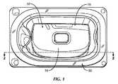
図面を詳細に参照すると、全体を通じて同一の符号により同一の要素を示し、図1から図5は、本開示の一実施形態に係る注射器を、全体として符号10により示す。図示の実施形態では、注射器10は、限定的でない単なる例として、ウェアラブル薬剤注射器等、ウェアラブル注射器(パッチ注射器)の形態であるが、本開示は、そのように限定されるものではない。以下により詳細に述べられるように、注射器10は、使用者に対し、パッケージ50に収められた状態(図1)で搬送可能とすることができる。 With reference to the drawings in detail, the same elements are indicated by the same reference numerals throughout, and FIGS. 1 to 5 indicate the syringe according to the embodiment of the present disclosure by
本技術分野の当業者により理解されるように、注射器10は、概して、使用者、例えば、患者の皮膚表面(図示せず)と接触するように構成された第1表面14を有するハウジング12を備え、第1表面14は、開口14aを有する。図示の実施形態では、第1表面14は、注射器ハウジング12の基面を画成するが、本開示は、そのように限定されるものではない。ハウジング12はまた、第1表面14とは反対側の第2表面16を有する。図示の実施形態では、第2表面16は、注射器ハウジング12の上部外面を画成するが、本開示は、そのように限定されるものではない。本技術分野の当業者により理解されるように、注射針(図示せず)は、注射器ハウジング12の内部に移動可能に取り付けられ、注射針の少なくとも先端が注射器ハウジング12の内部に収められる退避位置(図示せず)と、注射針の少なくとも先端が開口14aを介して注射器ハウジング12から突出し、使用者の皮膚(図示せず)に刺入する注射位置(図示せず)と、の間で移動可能である。 As will be appreciated by those skilled in the art, the
注射器10は、物質(図示せず)、例えば、医薬が収まる、封止されたカートリッジ60(図4)を受容するように構成される。カートリッジ60は、一端でピストン60aにより、他端で穿孔可能な隔壁60bにより封止される。注射器10へのカートリッジ60の挿入後(または挿入中)に、カートリッジ60は、本技術分野の当業者により充分に理解されるように、(隔壁60bの穿孔により)開封されるとともに、注射針に対して流体接続されて、カートリッジ60の内部の物質を、注射針を介して使用者に投与する。注射器ドア18は、注射器ハウジング21に対し、完全に閉じた位置(図1から図2B)と完全に開いた位置(図4)との間で移動可能に取り付けられる。注射器ドア18は、注射器10の内部にカートリッジ60を受容する際に開放することが可能である。図示の実施形態では、注射器ドア18は、カートリッジドアの形態であるが、本開示は、そのように限定されるものではない。カートリッジドア18は、カートリッジ60を、例えば、スライド式に受容する開放端18aと、カートリッジ60を収容する内部チャンネル18bと、を備える。内部チャンネル18bは、カートリッジ60を収容しかつ安定させるように寸法および形状を付与することが可能である。これに代え、内部チャンネル18bは、当該内部チャンネル18bにカートリッジ60を受容しかつ安定させることのできるカートリッジクレイドル、カートリッジトラック、個々の安定化部材またはこれらの組み合わせ等(図示せず)を備えるものであってもよい。 The
カートリッジドア18の少なくとも部分的に閉じた位置(図3)では、内部チャンネル18bは、注射器ハウジング12の外部からカートリッジ60を挿入するのに充分にアクセス可能な状態にはない。例えば、図示の実施形態では、カートリッジドア18の開放端18aは、内部チャンネル18bへのアクセスが妨げられ、よって、内部チャンネル18bにカートリッジ60が挿入されないように、注射器ハウジング12の一部により充分に隠され、覆われている。カートリッジドア18の完全に開いた位置(図4)では、カートリッジドア18の開放端18aは、カートリッジドア18の、開放端18aを介しおよび内部チャンネル18bへの挿入を可能とするのに充分なほどに露出させられ、覆いが外されている。 At least in the partially closed position of the cartridge door 18 (FIG. 3), the
図示の実施形態では、カートリッジドア18は、注射器ハウジング12に対し、例えば、開放端18aとは反対側の、内部チャンネル18bの閉じた遠位端に近いピン接続具20により、ピボット式に取り付けられるが、本開示は、そのように限定されるものではない。図1および図2Aに最もよく示されるように、カートリッジドア18は、完全に閉じた位置において、注射器ハウジング12の外郭と実質的に面が揃った状態にある。図4に示されるように、カートリッジドア18は、開いた位置において、注射器ハウジング12から離れる方向に枢動させられており、これにより、内部チャンネル18bは、カートリッジドア18の開放端18aからアクセス可能である。注射器ハウジング12に移動可能に取り付けられたカートリッジドア18の他の限定的でない例は、米国特許出願公開第2018/0154081号(発明の名称:「投薬装置に対するカートリッジの挿入」)に記載されており、その内容の全体が参照により本明細書に組み込まれる。 In the illustrated embodiment, the
付勢部材38は、注射器ハウジング12に内蔵し、カートリッジドア18を完全に開いた位置へ付勢するように構成することが可能である。図示の実施形態では、付勢部材38は、注射器ハウジング12の固定部材と移動可能なカートリッジドア18の部材との間に取り付けられたトーションばねの形態であり、つまり、トーションばね38は、一端で注射器ハウジング12に当接し、他端でカートリッジドア18に当接する。カートリッジドア18の閉じた位置では、トーションばね38は、少なくとも部分的に圧縮され、捻り(または撓み)の量に応じたポテンシャルエネルギを貯蔵する。トーションばね38は、(下にさらに詳細に述べられるように)その拘束が解かれると、伸展し、つまり、捻りが戻され、カートリッジドア18を完全に開いた位置に向けて移動させる。図示の実施形態では、トーションばね38の螺旋中心がピン接続具20の周辺に設けられるが、これとは異なる配置とすることも可能である。本技術分野における当業者に理解されるように、付勢部材38は、上記に代え、エネルギを貯蔵しおよび解放することが可能な他の部材の形態であってもよい。限定的でない例に、他のばね(例えば、コイルばねまたはリーフばね)等がある。これに代え、注射器10に付勢部材38が設けられなくてもよく、カートリッジドア18を手動により開いた位置へ移動可能とすることもできる。 The urging
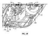
注射器10は、ピストン60aと係合しおよびカートリッジ60に亘ってこれを前進させて、カートリッジ60から物質を排出させるように配置され、構成された駆動アセンブリ22(図2A、図3および図4)をさらに備える。限定的でない一つの例では、駆動アセンブリ22は、入れ子式に互いにねじ接続されることで、少なくとも1つのシャフトの回転により、少なくとも他の1つのシャフトの直線的な移動を生じさせることが可能な複数のねじ付きシャフト、つまり、入れ子式の駆動アセンブリを備えることが可能であるが、本開示は、そのように限定されるものではない。図示のように、例えば、駆動アセンブリ22は、第1シャフト24と、第1シャフト24と入れ子式に接続され、第1シャフト24に対して軸方向に移動可能な第2シャフト26と、を備える。第1シャフト24の回転により、第2シャフト26が、退避状態(図4)から軸方向に駆動されて、軸方向に伸展し、ピストン60aと係合し、カートリッジ60に亘ってピストン60aを前進させる。退避状態では、駆動アセンブリ22は、カートリッジドア18の内部チャンネル18bから引き出され、完全に閉じた位置と完全に開いた位置との間でのカートリッジドア18の動きと干渉することはない。駆動アセンブリ22が軸方向に伸び始めるのに従い、第2シャフト26が内部チャンネル18bに進入する。 The
図示の実施形態では、追加の第3シャフト28が第1シャフト24にねじ接続されるとともに、第2シャフト26にねじ接続され、これにより、第1シャフト24を第2シャフト26と接続する。よって、第1シャフト24が回転すると、第3シャフト28が回転させられるとともに、軸方向に動かされ、もって、第2シャフト26が軸方向に移動する。このように、第2シャフト26は、第1シャフト24および第3シャフト28に対して軸方向に移動可能である。よって、第1、第3および第2シャフト24、26、28は、軸方向に入れ子式に嵌め込まれた駆動アセンブリを形成する。入れ子式の駆動アセンブリの他の限定的でない例は、米国特許出願公開第2016/0346478号(発明の名称:「入れ子式シリンジストッパ・ドライバ駆動アセンブリの線形回転スタビライザ」)に記載されており、その内容の全体が参照により本明細書に組み込まれる。 In the illustrated embodiment, an additional
本技術分野における当業者により理解されるように、注射器10は、注射器10およびコントローラ30や注射器10の他の電動要素に電力を供給する電源32の動作を指示する(図5に模式的に示される)コントローラ30、例えば、プロセッサをさらに備える。図示の実施形態では、電源32は、バッテリの形態であるが、本開示は、そのように限定されるものではない。(図5に模式的に示される)電源回路34は、バッテリ32をコントローラ30および注射器10の他の電動要素と電気的に接続する。例えば、電源回路34は、バッテリ32をアクチュエータ35と接続することも可能である。アクチュエータ36の限定的でない例に、モータ、ばね式のアクチュエータ、ガス式のアクチュエータ、化学式のアクチュエータ、電動式のアクチュエータ、電気機械式のアクチュエータまたはそれらの組み合わせ等がある。(本技術分野における当業者により充分に理解される方法での)コントローラ30によるアクチュエータ36の起動に際し、アクチュエータ36は、駆動アセンブリ22を(本技術分野における当業者により充分に理解されるように)駆動し、例えば、(本技術分野における当業者により充分に理解されかつ下に概説されるように)カートリッジ60と係合していない開始位置からカートリッジ60との係合に至る、相互接続された回転可能な一連のギア36a、23、22a(図2A、図3)を介して駆動するように構成される。 As will be appreciated by those skilled in the art, the
注射器10の使用に先立ち、コントローラ30は、注射器10の少なくとも1つの要素の動作性に関する初めの自己テストを実施し、注射器10が正しく機能し、使用の準備が整っているかどうかまたは注射器10に不具合が生じているかどうか、つまり、テストの対象である少なくとも1つの要素のいずれかが正しく機能していないかどうかを判定するように構成される。コントローラ30は、電源の投入をもってこの自己テストを実施するようにプログラムすることが可能である。これに代え、自己テストは、注射器10自体によるかまたは遠隔操作により、使用者が起動させるようにすることも可能である。テストの対象となり得る注射器10の作動要素の網羅的でない例に、注射器10の移動可能な要素、アクチュエータ36、電源32、駆動アセンブリ22およびコントローラ30の他の機能要素の動きを検出するように構成されたセンサ(図示せず)、例えば、光学センサがある。自己テストは、単一の「可」(pass)または「不可」(fail)との結果を有する。つまり、自己テストにおいて「可」との結果を得るには、自己テストの間にテストが実施される注射器10の全ての要素が正しく機能していなければならない。他方で、自己テストの間にテストが実施される注射器10のいずれかの要素が正しく機能していない場合は、自己テストの結果は、「不可」となる。 Prior to the use of the
カートリッジドア18は、少なくとも部分的に閉じた位置(図3)で初めにロックがかけられており、自己テストが完了し、「可」との結果が得られるまで、注射器10へのカートリッジ60の挿入が妨げられる。つまり、移動可能なロック機構が、完全に閉じた位置から完全に開いた位置へのカートリッジドア18の経路に進入し、カートリッジドア18が完全に開いた位置に到達可能となるのを阻害する。移動可能なロック機構は、自己テストの「可」との結果が得られた場合にのみ、カートリッジドア18の経路から引き出されるように構成される。その後、カートリッジドア18は、ロックが解除され、完全に開いた位置に移動することが可能となり、注射器10にカートリッジ60を挿入することが可能となる。 The
ロック機構は、注射器10が自己テストを通過し、よって、正しく機能していることが確認されない限り注射器10にカートリッジ60を挿入する(そして、続いて、開封される)ことができないため、未使用の、封止されたカートリッジ60の完全性を保持する点で有利である。自己テストによるテストが実施されたいずれかの要素により「不可」との自己テストの結果が生じた場合は、ロック機構は、カートリッジドア18の経路から引き出されず、これにより、使用者が不具合のある注射器10にカートリッジ60を挿入し、これを浪費することを回避する。 The locking mechanism is unused because the
図示の実施形態では、駆動アセンブリ22は、移動可能なロック機構として動作するが、本開示は、そのように限定されるものではない。図2Aに最もよく示されるように、駆動アセンブリ22は、カートリッジドア18が完全に閉じた位置に向けられている場合に、カートリッジドア18の内部チャンネル18bと軸方向に整列する。図3に示されるように、駆動アセンブリ22は、初めに、つまり、自己テストの「可」との結果が得られる前に、第2シャフト26の少なくとも遠位部26aがカートリッジドア18の内部チャンネル18bに進入する、部分的に伸展させられた状態に配置される。よって、第2シャフト26により、カートリッジドア18が完全に開いた位置に移動することが妨げられる。一例として、開放端18aに近いカートリッジドア18からの突起18cが、完全に閉じた位置から完全に開いた位置へのカートリッジドア18の移動の間に、第2シャフト26の遠位端26aと接触することで、カートリッジドア18が完全に開いた位置に向けてさらに移動することを阻害する。駆動アセンブリ22は、自己テストで「可」との結果が得られた場合にのみ、退避位置(図4)に引き出され、つまり、アクチュエータ36は、駆動アセンブリ22を、駆動アセンブリ22が伸展する回転方向とは反対の回転方向に駆動する。退避させられた状態では、駆動アセンブリ22は、カートリッジドア18の経路から引き出される。 In the illustrated embodiment, the
一実施形態では、電気絶縁部材40を、初めに、電気絶縁部材40が電源32の少なくとも1つの(正または負の)接点32aとこれに対応する電源回路34の少なくとも1つの(電源の接点32aとは反対の極性の)対向接点34aとの間に介在させられる第1状態に配置させ(図2A、図2Bおよび模式的に図5)、(コントローラ30および他の注射器要素に対する電力の供給がないように)電源32の電源回路34に対する接続を電気的に遮断して、注射器10の使用前における電源32のドレナージを回避することが可能である。電気絶縁部材40は、電気絶縁部材40が電源32の少なくとも1つの接点32aと電源回路34の対応の少なくとも1つの対向接点34aとの間から除外される第2状態(図3、図4)へ移動可能であり、これにより、電源32を電源回路34と電気的に接続し、コントローラ30を含む注射器要素に電力を供給する。 In one embodiment, the electrical insulating
図示の実施形態では、図2Aから図4に示されるように、電気絶縁部材40は、カートリッジドア18に結合されたポリマーアームの形態である。しかし、理解されるように、電気絶縁部材40は、現在知られておりまたは将来知られることになる代わりの電気絶縁材料から構成することが可能である。アーム40は、カートリッジドア18と、本技術分野における当業者により充分に理解される方法で固定的に結合することが可能である。つまり、アーム40は、カートリッジドア18の移動、例えば、枢動とともに移動し、例えば、枢動することが可能である。これに代え、アーム40は、カートリッジドア18と一体的に形成することも可能であり、つまり、カートリッジドア18と単一的かつモノリシックであってもよい。 In the illustrated embodiment, as shown in FIGS. 2A-4, the electrical insulating
アーム40は、カートリッジドア18の完全に閉じた初めの位置で第1状態に配置されるように構成され、つまり、形状、寸法、角度が付与されまたはこれらの組み合わせが付与される(図2A、図2B)。アーム40はまた、完全に閉じた位置から開いた位置へのカートリッジドア18の移動とともに、第2状態(図3、図4)へ移動するように構成される。図示の実施形態では、図3に示されるように、アーム40は、自己テストにより「可」との結果が得られる前にカートリッジドア18が駆動アセンブリ22により妨げられる場合に、カートリッジドア18の部分的に閉じた位置で第2状態に配置されるように構成される。 The
本技術分野における当業者により理解されるように、電気絶縁部材40は、注射器10の他の可動要素に取り付けることが可能であり、注射器ハウジング12に対し、アーム40が本明細書に記載される機能を発揮することを可能とする態様で別々にかつ移動可能に取り付けることも可能である。例えば、限定を伴わずに、電気絶縁部材40は、典型的な使用者により取外可能なバッテリアイソレータの形態であってもよく、電気絶縁部材40は、米国特許出願公開第2013/0310753号(発明の名称:「バッテリ作動式の投薬装置に選択的に給電する方法およびそのための装置」)に記載されるように注射器10に採用することも可能であり、その内容の全体が参照により本明細書に組み込まれる。理解されるように、電気絶縁部材40は、第1状態で電源32の直接接点と電源回路34の対向接点との間に介在させることも可能であるし、これに代え、電気絶縁部材40は、第1状態で電源回路34に沿った他の箇所に形成された対向接点同士の間に介在させることも可能である。 As will be appreciated by those skilled in the art, the electrically insulating
使用に際し、注射器10は、初めに、カートリッジドア18が完全に閉じた位置にある状態で使用者に分配することが可能である。例えば、カートリッジドア18を開いた位置へ付勢するのに付勢部材38が採用される場合に、注射器パッケージ50により、付勢部材38の力に抗してカートリッジドア18を完全に閉じた位置(図1)に維持することが可能である。しかし、理解されるように、カートリッジドア18は、現在知られておりまたは将来知られることになる他の機構により完全に閉じた位置に配置することも可能である。一例として、取外可能なライナー(図示せず)をカートリッジドア18および注射器ハウジング12の部分に配置して、ドア18を閉じた位置に維持することが可能である。これに代え、カートリッジドア18に、例えば、(付勢部材38の存在の有無を問わず)完全に閉じた位置でロックをかけることも可能である。 In use, the
注射器10において、電気絶縁部材40が初めに電源32の少なくとも1つの接点32aと電源回路34の対応の少なくとも1つの対向接点34aとの間に介在させられる場合に、電源32は、初めに、電気的な接続が遮断され、そのドレナージが回避される。使用者は、電気絶縁部材40を電源32の少なくとも1つの接点32aと電源回路34の対応の少なくとも1つの対向接点34aとの間から手動で引き、取り外して、コントローラ30に電源を投入し、自己テストを開始させることが可能である。 In the
カートリッジドア18が、例えば、付勢部材38により開いた位置へ付勢される場合は、注射器10のそのパッケージ50からの取り出しにより、付勢部材38が完全に閉じた位置から開いた位置に向けて動くことが可能となるが、結果として、駆動アセンブリ22により部分的に閉じた位置で動きが妨げられるに過ぎない(図3)。これに代え、カートリッジドア18がその開いた位置へ付勢されない場合に、使用者は、カートリッジドア18を完全に閉じた位置から部分的に閉じた位置へ手動で移動させることが可能である。電気絶縁部材40がカートリッジドア18に結合される場合に、電気絶縁部材40を、完全に閉じた位置から部分的に閉じた位置へのカートリッジドア18の移動の間に、(当該部材40の第2状態に至らせるように)電源32の少なくとも1つの接点32aと電源回路34の対応の少なくとも1つの対向接点34aとの間から除外し、コントローラ30に電源を投入し、自動的に自己テストを開始させることが可能である。カートリッジドア18は、カートリッジドア18の経路への駆動アセンブリ22(または他の移動可能なロック機構)の進入により、先に説明されたように、完全に開いた位置に到達することが阻害される。これに代え、電気絶縁部材40が採用されない場合に、使用者は、注射器10と接続され、例えば、組み合わされた起動スイッチ(図示せず)または遠隔移動装置(図示せず)により装置に電源を投入し、自己テストを開始させることが可能である。 When the
自己テストが生じた結果が「不可」である場合は、カートリッジドア18を、少なくとも部分的に閉じた位置でロックがかけられたままに残して、カートリッジ60が注射器10に挿入されることを阻害するとともに、「不可」インジケータを作動させることが可能である。例えば、不可を示す可聴音および/または可視インジケータまたはそれらの組み合わせ等を起動させることが可能である。よって、使用者は、カートリッジ60を挿入し、開封した後に注射器10の不可を判定することで、その後、新しい注射器10と新しいカートリッジ60との双方を必要とする代わりに、他の注射器10を取得し、その新たに取得された注射器10との使用に備え、カートリッジ18を回収することが可能である。 If the result of the self-test is "impossible", the
これとは異なり、自己テストが生じた結果が「可」である場合は、コントローラ30は、アクチュエータ36に対し、(先に説明されたように)カートリッジドア18の経路から駆動アセンブリ22を引き出し、カートリッジドア18のロックを解除し、カートリッジドア18が完全に開いた位置へ動かされるのを可能とするように指示する。例えば、付勢部材38が採用される場合に、自己テストの合格により、駆動アセンブリ22がカートリッジドア18の経路から引き出されて、付勢部材38の制約が解除されることで、カートリッジドア18は、付勢部材38の力のもとで完全に開いた位置へ自動的に動かされる。これに代え、付勢部材38が採用されない場合に、使用者は、駆動アセンブリ22がカートリッジドア18の経路から引き出された後、カートリッジドア18を完全に開いた位置へ手動で移動させることが可能である。そして、さらに、付勢部材38は、カートリッジドア18を部分的に開いた状態に移動させ、使用者は、カートリッジドア18を完全に開いた状態に移動させるのを終了することが可能である。可聴および/または可視インジケータまたはそれらの組み合わせ等により、使用者に対し、自己テストにより「可」との結果が得られ、カートリッジドア18のロックが解除されたことを知らせることが可能である。 In contrast, if the result of the self-test is "OK", the
カートリッジドア18の完全に開いた位置では、カートリッジドア60を、内部チャンネル18bに挿入することが可能であり(図4)、その後、カートリッジドア18を完全に閉じた位置に復帰させ、カートリッジ60を駆動アセンブリ22と軸方向に整列させることが可能である。コントローラ30は、ここで、アクチュエータ36に対し、駆動アセンブリ22をカートリッジドア18の内部チャンネル18bに進入させるように指示し、本技術分野における当業者により充分に理解されるように、カートリッジ60と係合させ、カートリッジ60を注射針(図示せず)と流体接続させ、さらに、物質をカートリッジ60からおよび注射針を介して注射器10から排出させることが可能である。 In the fully open position of the
以上で述べられた実施形態に対し、その広義の発明概念から逸脱することなく変更を加え得ることが、本技術分野の当業者により理解される。例えば、限定を伴わずに、自己テストは、注射器10と組み合わされて、自己テストに関してコントローラ30により実行される機能の幾つかまたは全てを実行する二次装置、例えば、移動装置を含んでもよい。移動装置はまた、使用者および/またはカートリッジ60の(例えば、バーコートを走査することによる)認証等、他のまたは追加の機能を実行することも可能である。よって、本開示は、開示された特定の実施形態に限定されるものではなく、本開示の精神および範囲における、添付の請求の範囲に記載される種々の変更例を含むことが意図されたものである。 It will be understood by those skilled in the art that modifications may be made to the embodiments described above without departing from the broadly defined concept of the invention. For example, without limitation, the self-test may include a secondary device, eg, a mobile device, that, in combination with the
Claims (14)
Translated fromJapanese注射器ハウジングと、
前記注射器ハウジングに対し、完全に閉じた位置と完全に開いた位置との間で移動可能に取り付けられた注射器ドアであって、初めに、少なくとも部分的に閉じた位置でロックがかけられて、当該注射器への前記カートリッジの挿入を阻害する注射器ドアと、
当該注射器を構成する少なくとも1つの要素の動作性に関する初めの自己テストを実行可能に構成され、前記自己テストが、単一の可または不可との結果を有するコントローラであって、前記自己テストの可との結果が得られた場合にのみ、前記注射器ドアがロックを解除され、前記完全に開いた位置へ移動させられることが可能となり、当該注射器への前記カートリッジの挿入を可能とするコントローラと、
を備える注射器。A syringe configured to accept a cartridge containing the substance to be administered.
Syringe housing and
A syringe door that is movably attached to the syringe housing between a fully closed position and a fully open position, initially locked at least in a partially closed position.A syringe door that prevents the cartridge from being inserted into the syringe,
A controller that is configured to be able to perform an initial self-test on the operability of at least one component of the syringe and that the self-test has a single passable or unacceptable result. Only when the result is obtained, the syringe door can be unlocked and moved to the fully open position, and a controller that allows the cartridge to be inserted into the syringe.
Syringe equipped with.
請求項1に記載の注射器。A movable locking mechanism that projects into the path of the syringe door from the fully closed position to the fully open position and prevents the syringe door from reaching the fully open position. It further comprises a locking mechanism configured to be pulled out of the pathway of the syringe door when the self-testing result is obtained.
The syringe according to claim 1.
前記駆動アセンブリは、前記カートリッジから解放される退避状態と、前記カートリッジと係合させられる伸展状態と、の間で動作可能であり、
前記駆動アセンブリは、前記完全に閉じた位置から前記完全に開いた位置へ移動する場合に、初めに、前記注射器ドアの経路に突出して、前記自己テストの可との結果が得られる前に前記注射器ドアが前記完全に開いた位置に移動するのを阻害する、部分的に伸展させられた状態に向けられ、ここに、前記駆動アセンブリは、前記自己テストの可との結果が得られた場合に、前記退避状態に退避させられて、前記注射器ドアの経路から引き出される、
請求項1または2に記載の注射器。Further comprising a drive assembly configured to engage with the cartridge and allow the material to be ejected from the cartridge by inserting the cartridge into the syringe.
The drive assembly can operate between a retracted state released from the cartridge and an extended state engaged with the cartridge.
When moving from the fully closed position to the fully open position, the drive assembly first protrudes into the path of the syringe door and is said to be self-testable before the result is obtained. If the syringe door is directed to a partially extended state that prevents it from moving to the fully open position, where the drive assembly is self-testable. It is retracted into the retracted state and pulled out from the path of the syringe door.
The syringe according to claim 1 or 2.
請求項1から3のいずれか一項に記載の注射器。The syringe door comprises a cartridge door having an open end and an internal channel that receives the cartridge through the open end, at least in a partially closed position, the open end is provided by the syringe housing. In the fully open position, the open end is receptibly exposed to the cartridge through the open end and into the internal channel, hiding to prevent insertion of the cartridge into the internal channel.
The syringe according to any one of claims 1 to 3.
前記駆動アセンブリは、前記内部チャンネルから引き出される退避状態と、前記内部チャンネルに進められ、前記カートリッジと係合させられる伸展状態と、の間で動作可能であり、
前記駆動アセンブリは、前記自己テストの可との結果が得られる前に、部分的に伸展させられた状態に向けられ、前記内部チャンネルに突出することで、前記カートリッジドアが前記完全に開いた位置へ移動するのを阻害し、ここに、前記駆動アセンブリは、前記自己テストの可との結果が得られた場合に、前記退避状態に退避させられる、
請求項4に記載の注射器。Further comprising a drive assembly configured to engage the cartridge and eject the material from the cartridge when the cartridge is inserted into the internal channel and the cartridge door is in the fully closed position.
The drive assembly can operate between a retracted state drawn from the internal channel and an extended state advanced to the internal channel and engaged with the cartridge.
The drive assembly is oriented to a partially extended state and projecting into the internal channel to allow the cartridge door to be in the fully open position before a self-testable result is obtained. The drive assembly is retracted into the retracted state when the self-testing result is obtained.
The syringe according to claim 4.
請求項4または5に記載の注射器。Further comprising an urging member for urging the cartridge door towards the fully open position.
The syringe according to claim 4 or 5.
前記電源を前記コントローラと電気的に接続する電源回路と、
電気絶縁部材と、
をさらに備え、
前記電気絶縁部材は、第1状態から第2状態へ移動可能であり、
前記第1状態では、前記電気絶縁部材が、前記電源の少なくとも1つの接点と前記電源回路の対応する少なくとも1つの対向接点との間に介在させられて、前記電源の前記電源回路に対する接続が遮断され、
前記第2状態では、前記電気絶縁部材が、前記電源の前記少なくとも1つの接点と前記電源回路の前記対応の少なくとも1つの対向接点との間から除外されて、前記電源が前記電源回路と接続され、前記コントローラに電力を供給する、
請求項1から6のいずれか一項に記載の注射器。Power supply and
A power supply circuit that electrically connects the power supply to the controller,
With electrical insulation
With more
The electrically insulating member can be moved from the first state to the second state.
In the first state, the electrically insulating member is interposed between at least one contact of the power supply and at least one corresponding opposite contact of the power supply circuit to break the connection of the power supply to the power supply circuit. Being done
In the second state, the electrical insulating member is excluded from between the at least one contact of the power supply and the corresponding at least one opposite contact of the power supply circuit, and the power supply is connected to the power supply circuit. Power the controller,
The syringe according to any one of claims 1 to 6.
前記アームは、前記注射器ドアの前記完全に閉じた位置において、初めに、前記第1状態に配置され、前記完全に閉じた位置からの前記注射器ドアの移動に際して、前記第2状態に動かされる、
請求項7に記載の注射器。The electrically insulating member is an arm coupled to the syringe door.
Thearm is initially placed in the first state at the fully closed position of the syringe door and is moved to the second state upon movement of the syringe door from the fully closed position.
The syringe according to claim 7.
前記注射器のコントローラにより、少なくとも1つの注射器要素の動作性に関する初めの自己テストを実施し、前記自己テストは、単一の可または不可との結果を有する工程と、
前記自己テストの可との結果が得られた場合にのみ、注射器ドアのロックを解除し、前記注射器ドアは、前記注射器のハウジングに対し、完全に閉じた位置と完全に開いた位置との間で移動可能に取り付けられ、前記注射器ドアは、先に少なくとも部分的に閉じた位置でロックがかけられ、前記注射器への前記カートリッジの挿入を阻害する工程と、
を含む、方法。A method of operating a syringe that is configured to accept a cartridge containing the substance to be administered.
An initial self-test for the operability of at least one syringe element is performed by the syringe controller, and the self-test has a single acceptable or unacceptable result.
Only if the result of the self-test is acceptable is the syringe door unlocked and the syringe door is between the fully closed and fully open positions with respect to the syringe housing. The syringe door is previously locked at least in a partially closed position to prevent insertion of the cartridge into the syringe.
Including methods.
請求項9に記載の方法。The step of releasing the lock comprises pulling out the locking mechanism from a state protruding from the completely closed position to the fully open position in the path of the syringe door, wherein the locking mechanism first pulls the syringe. Preventing the door from reaching the fully open position,
The method according to claim 9.
請求項9または10に記載の方法。The unlocking step is capable of operating between retracted and extended states and is configured to engage the cartridge and expel the substance from the cartridge by inserting the cartridge into the syringe. The drive assembly is partially extended and protrudes from the fully closed position to the fully open position in the path of the syringe door to the retracted state of the drive assembly. Including withdrawal,
The method according to claim 9 or 10.
前記ロックを解除する工程は、退避状態と伸展状態との間で動作可能であり、前記注射器への前記カートリッジの挿入により前記カートリッジと係合しおよび前記カートリッジから前記物質を排出させるように構成された駆動アセンブリを、当該駆動アセンブリの部分的に伸展させられ、前記カートリッジドアの前記内部チャンネルに突出する状態から、当該駆動アセンブリが前記内部チャンネルから引き出される前記退避状態へ引き出すことを含む、
請求項9から11のいずれか一項に記載の方法。The syringe door comprises a cartridge door having an open end and an internal channel that receives the cartridge through the open end, at least in a partially closed position, the open end being said by thehousing. In a fully open position, the open end responsively exposes the cartridge to the internal channel through the open end, hiding to prevent insertion of the cartridge into the internal channel.
The unlocking step is capable of operating between a retracted state and an extended state, and is configured to engage the cartridge and expel the substance from the cartridge by inserting the cartridge into the syringe. This includes pulling the drive assembly from a state in which the drive assembly is partially extended and projecting into the internal channel of the cartridge door to a retracted state in which the drive assembly is pulled out of the internal channel.
The method according to any one of claims 9 to 11.
前記電気絶縁部材を第1状態から第2状態へ動かす工程をさらに含み、
前記第1状態では、前記電気絶縁部材を、前記電源の少なくとも1つの接点と前記電源回路の対応する少なくとも1つの対向接点との間に介在させて、前記電源の前記電源回路に対する接続を遮断し、
前記第2状態では、前記電気絶縁部材を、前記電源の前記少なくとも1つの接点と前記電源回路の前記対応の少なくとも1つの対向接点との間から取り除いて、前記電源を前記電源回路と接続させるとともに、前記コントローラに電力を供給する、
方法。The method ofclaim 12 , wherein the syringe further comprises a power source, a power supply circuit that electrically connects the power source to the controller, and an electrically insulating member.
The step of moving the electrically insulating member from the first state to the second state is further included.
In the first state, the electrically insulating member is interposed between at least one contact of the power supply and at least one corresponding opposite contact of the power supply circuit to break the connection of the power supply to the power supply circuit. ,
In the second state, the electrical insulating member is removed from between the at least one contact of the power supply and the corresponding at least one opposite contact of the power supply circuit to connect the power supply to the power supply circuit. Power the controller,
Method.
前記電気絶縁部材を前記第1状態から前記第2状態へ動かす工程は、前記カートリッジドアを前記完全に閉じた位置から移動させることを含む、
請求項13に記載の方法。The electrically insulating member is an arm coupled to thecartridge door.
The step of moving the electrically insulating member from the first state to the second state includes moving thecartridge door from the completely closed position.
13. The method of claim 13.
Applications Claiming Priority (3)
| Application Number | Priority Date | Filing Date | Title |
|---|---|---|---|
| US201762543701P | 2017-08-10 | 2017-08-10 | |
| US62/543,701 | 2017-08-10 | ||
| PCT/US2018/045004WO2019032375A1 (en) | 2017-08-10 | 2018-08-02 | Injector self-test and injector door unlocking mechanism responsive thereto |
Publications (2)
| Publication Number | Publication Date |
|---|---|
| JP2020526359A JP2020526359A (en) | 2020-08-31 |
| JP6840891B2true JP6840891B2 (en) | 2021-03-10 |
Family
ID=63209732
Family Applications (1)
| Application Number | Title | Priority Date | Filing Date |
|---|---|---|---|
| JP2020507099AActiveJP6840891B2 (en) | 2017-08-10 | 2018-08-02 | Syringe self-test and corresponding syringe door unlocking mechanism |
Country Status (5)
| Country | Link |
|---|---|
| US (1) | US11642457B2 (en) |
| EP (1) | EP3664865B1 (en) |
| JP (1) | JP6840891B2 (en) |
| CN (1) | CN111163818B (en) |
| WO (1) | WO2019032375A1 (en) |
Families Citing this family (6)
| Publication number | Priority date | Publication date | Assignee | Title |
|---|---|---|---|---|
| EP1762259B2 (en) | 2005-09-12 | 2025-01-01 | Unomedical A/S | Inserter for an infusion set with a first and second spring units |
| WO2012123274A1 (en) | 2011-03-14 | 2012-09-20 | Unomedical A/S | Inserter system with transport protection |
| JP7130658B2 (en)* | 2017-03-16 | 2022-09-05 | ノバルティス アーゲー | syringe device |
| US11458292B2 (en) | 2019-05-20 | 2022-10-04 | Unomedical A/S | Rotatable infusion device and methods thereof |
| GB2591977B (en)* | 2019-09-27 | 2022-03-16 | Owen Mumford Ltd | Auto-Injector |
| WO2022147054A1 (en)* | 2021-01-04 | 2022-07-07 | Becton, Dickinson And Company | Ball joint-style, non-fixed coupling between a pusher plate and plunger in a syringe barrel |
Family Cites Families (19)
| Publication number | Priority date | Publication date | Assignee | Title |
|---|---|---|---|---|
| CA2421133C (en)* | 2000-09-08 | 2012-06-26 | Insulet Corporation | Devices, systems and methods for patient infusion |
| ES2385140T3 (en)* | 2004-02-18 | 2012-07-18 | Ares Trading S.A. | Portable electronic injection device for injecting liquid medications |
| WO2006024650A2 (en) | 2004-09-02 | 2006-03-09 | Novo Nordisk A/S | Medical device adapted for detection of drug condition |
| FR2908176B1 (en)* | 2006-11-08 | 2008-12-19 | Fresenius Vial Soc Par Actions | DEVICE FOR MONITORING THE OPENING OR CLOSING OF A CLAMP IN A VOLUMETRIC PUMP |
| US8303535B2 (en) | 2008-09-10 | 2012-11-06 | Hoffman-La Roche Inc. | Delivery device for use with a therapeutic drug |
| CN103727021B (en)* | 2008-10-22 | 2018-01-23 | 生物技术公司 | Method for detecting at least one dysfunction in infusion assembly |
| US10071196B2 (en) | 2012-05-15 | 2018-09-11 | West Pharma. Services IL, Ltd. | Method for selectively powering a battery-operated drug-delivery device and device therefor |
| DK2714147T3 (en) | 2011-05-25 | 2017-07-24 | Sanofi Aventis Deutschland | MEDICINAL APPLICATION DEVICE WITH DISPENSING INTERFACE SENSOR AND PROCEDURE TO CONTROL THE DEVICE |
| US8808230B2 (en) | 2011-09-07 | 2014-08-19 | Asante Solutions, Inc. | Occlusion detection for an infusion pump system |
| KR20140000766U (en) | 2012-07-27 | 2014-02-05 | 송득영 | Automatic door system of infusion pump |
| CA2808738C (en)* | 2012-09-26 | 2014-03-18 | Gadlight, Inc | Portable medicine injection device and metering system |
| JP6240090B2 (en) | 2012-12-13 | 2017-11-29 | パナソニックヘルスケアホールディングス株式会社 | Drug injection device |
| US9421323B2 (en)* | 2013-01-03 | 2016-08-23 | Medimop Medical Projects Ltd. | Door and doorstop for portable one use drug delivery apparatus |
| US10335550B2 (en)* | 2014-04-25 | 2019-07-02 | Phc Holdings Corporation | Pharmaceutical injection device |
| WO2016033496A1 (en)* | 2014-08-28 | 2016-03-03 | Unitract Syringe Pty Ltd | Skin sensors for drug delivery devices |
| EP3031486A1 (en)* | 2014-12-09 | 2016-06-15 | CONARIS research institute AG | Medication cartridges for optimised dosing |
| US10149943B2 (en) | 2015-05-29 | 2018-12-11 | West Pharma. Services IL, Ltd. | Linear rotation stabilizer for a telescoping syringe stopper driverdriving assembly |
| CN113181477B (en) | 2015-06-04 | 2023-07-14 | 麦迪麦珀医疗工程有限公司 | Cartridge insertion for drug delivery device |
| CN110536709A (en)* | 2017-03-16 | 2019-12-03 | 诺瓦提斯公司 | Injection device |
- 2018
- 2018-08-02JPJP2020507099Apatent/JP6840891B2/enactiveActive
- 2018-08-02CNCN201880064400.5Apatent/CN111163818B/enactiveActive
- 2018-08-02EPEP18755666.7Apatent/EP3664865B1/enactiveActive
- 2018-08-02WOPCT/US2018/045004patent/WO2019032375A1/ennot_activeCeased
- 2018-08-02USUS16/637,043patent/US11642457B2/enactiveActive
Also Published As
| Publication number | Publication date |
|---|---|
| US11642457B2 (en) | 2023-05-09 |
| CN111163818A (en) | 2020-05-15 |
| WO2019032375A1 (en) | 2019-02-14 |
| CN111163818B (en) | 2021-05-14 |
| US20200238003A1 (en) | 2020-07-30 |
| EP3664865A1 (en) | 2020-06-17 |
| JP2020526359A (en) | 2020-08-31 |
| EP3664865B1 (en) | 2021-06-02 |
Similar Documents
| Publication | Publication Date | Title |
|---|---|---|
| JP6840891B2 (en) | Syringe self-test and corresponding syringe door unlocking mechanism | |
| US12383676B2 (en) | Auto injector with charger safety | |
| JP7273120B2 (en) | Syringe | |
| US11607486B2 (en) | Injector device | |
| CN103945881B (en) | There is initial lock state, the centre note medical delivery device to state and drug delivery state | |
| JP6261725B2 (en) | Drug injection device | |
| JP2013501554A (en) | Cap for portable drug delivery device and such drug delivery device | |
| JP2013505037A (en) | Latching and control device for integration in medical devices | |
| ES2824788T3 (en) | Medication delivery device with mechanical locking system | |
| KR20140135200A (en) | Medical device comprising a socket unit for connecting a device for providing medical liquids and device for providing medical liquids, comprising a plug unit for connection to a medical device | |
| JP7290753B2 (en) | Cassettes, drug infusion devices and drug infusion systems | |
| WO2015165757A1 (en) | A disposable cassette for storing and delivering a medical drug | |
| JP6852220B2 (en) | Syringe power-on mechanism | |
| WO2018166699A1 (en) | Injector device | |
| CN117881442A (en) | Automatic injection device and cassette system with a cap removal mechanism | |
| CN117881443A (en) | Automatic injection device with clutch release function | |
| IT202200026286A1 (en) | Device for subcutaneous delivery of a drug | |
| HK40012846A (en) | Injector device | |
| HK1262201A1 (en) | Auto injector with charger safety | |
| HK1262201B (en) | Auto injector with charger safety |
Legal Events
| Date | Code | Title | Description |
|---|---|---|---|
| A621 | Written request for application examination | Free format text:JAPANESE INTERMEDIATE CODE: A621 Effective date:20200330 | |
| A871 | Explanation of circumstances concerning accelerated examination | Free format text:JAPANESE INTERMEDIATE CODE: A871 Effective date:20200330 | |
| A975 | Report on accelerated examination | Free format text:JAPANESE INTERMEDIATE CODE: A971005 Effective date:20200703 | |
| A131 | Notification of reasons for refusal | Free format text:JAPANESE INTERMEDIATE CODE: A131 Effective date:20200714 | |
| A521 | Request for written amendment filed | Free format text:JAPANESE INTERMEDIATE CODE: A523 Effective date:20200925 | |
| A131 | Notification of reasons for refusal | Free format text:JAPANESE INTERMEDIATE CODE: A131 Effective date:20201110 | |
| A521 | Request for written amendment filed | Free format text:JAPANESE INTERMEDIATE CODE: A523 Effective date:20210112 | |
| TRDD | Decision of grant or rejection written | ||
| A01 | Written decision to grant a patent or to grant a registration (utility model) | Free format text:JAPANESE INTERMEDIATE CODE: A01 Effective date:20210209 | |
| A61 | First payment of annual fees (during grant procedure) | Free format text:JAPANESE INTERMEDIATE CODE: A61 Effective date:20210217 | |
| R150 | Certificate of patent or registration of utility model | Ref document number:6840891 Country of ref document:JP Free format text:JAPANESE INTERMEDIATE CODE: R150 | |
| R250 | Receipt of annual fees | Free format text:JAPANESE INTERMEDIATE CODE: R250 | |
| R250 | Receipt of annual fees | Free format text:JAPANESE INTERMEDIATE CODE: R250 |