JP6840614B2 - Braking device for orbital machinery - Google Patents
Braking device for orbital machineryDownload PDFInfo
- Publication number
- JP6840614B2 JP6840614B2JP2017089204AJP2017089204AJP6840614B2JP 6840614 B2JP6840614 B2JP 6840614B2JP 2017089204 AJP2017089204 AJP 2017089204AJP 2017089204 AJP2017089204 AJP 2017089204AJP 6840614 B2JP6840614 B2JP 6840614B2
- Authority
- JP
- Japan
- Prior art keywords
- line
- fluid pressure
- working fluid
- pressure cylinder
- fluid
- Prior art date
- Legal status (The legal status is an assumption and is not a legal conclusion. Google has not performed a legal analysis and makes no representation as to the accuracy of the status listed.)
- Active
Links
Images

Landscapes
- Fluid-Pressure Circuits (AREA)
- Braking Systems And Boosters (AREA)
- Regulating Braking Force (AREA)
- Carriers, Traveling Bodies, And Overhead Traveling Cranes (AREA)
Description
Translated fromJapanese本発明は、軌道走行式機械の制動装置に関するものである。 The present invention relates to a braking device for a track-traveling machine.
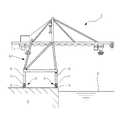
図3は一般的な軌道走行式機械としてのコンテナクレーンの一例を示すものであって、1はコンテナクレーン、2はコンテナクレーン1が配備される港湾、3は港湾2における岸壁、4は岸壁3に図3の紙面と直交する方向へ延びるよう敷設されたレールであり、コンテナクレーン1のクレーン本体5の支持脚6には、レール4に沿って転動自在な走行車輪7を有する走行装置8が取り付けられている。 FIG. 3 shows an example of a container crane as a general orbital traveling machine, where 1 is a container crane, 2 is a port where a container crane 1 is deployed, 3 is a quay at a
前記コンテナクレーン1は、荷役作業中に強風に煽られると、運転者の意に反して走行が止まらず、逸走してしまい、隣接する機械や近接構造物への衝突や倒壊に至る虞がある。 If the container crane 1 is blown by a strong wind during cargo handling work, the traveling of the container crane 1 does not stop against the intention of the driver and runs away, which may cause a collision or collapse with an adjacent machine or a nearby structure. ..
このため、前述の如き軌道走行式機械の逸走を防止する装置として、従来、例えば、特許文献1に開示されているようなクランプ装置がある。該クランプ装置は、先端部に挟み部が形成された一対の接触子をその略中間部が軸を中心として回動自在となるよう連結した挟み機構と、該挟み機構における前記接触子の基端部に設けられ且つ該接触子の基端部間を狭めて前記挟み部が常時レールを挟む閉方向へ前記接触子を回動させるようにしたばね機構と、前記一対の接触子の基端部に形成されたカム受部をその内側から押し開く方向へ駆動して前記挟み部によるレールの挟み付けを解放するための回転カムとを備えている。 For this reason, as a device for preventing the escape of the orbital traveling machine as described above, there is a clamp device conventionally disclosed in, for example, Patent Document 1. The clamp device includes a pinching mechanism in which a pair of contacts having a pinching portion formed at the tip thereof are connected so that a substantially intermediate portion thereof is rotatable about an axis, and a base end of the contact in the pinching mechanism. A spring mechanism provided in the portion and narrowing between the base ends of the contacts so that the sandwich always rotates the contacts in a closing direction that sandwiches the rail, and the base ends of the pair of contacts. It is provided with a rotary cam for driving the cam receiving portion formed in the above in a direction of pushing open from the inside and releasing the pinching of the rail by the sandwiching portion.
しかしながら、特許文献1に開示されたクランプ装置では、レールを両側から挟み付ける方式を採用しているため、レール面との摩擦係数を高めるためにクランプ装置側の接触面にギザギザの歯を付けたり、或いは接触面を硬化させてヤスリのようにしたりしている場合、レールの側面に傷を付けてしまう可能性があった。又、レールの側面の精度が低く、その幅方向における中心線から側面までの寸法に左右でばらつきが生じているような場合、若しくはレールの腐食等が生じている場合、前記挟み部による挟み付けが均一に行われずに締付力が大きく低下してしまい、充分な保持力が得られなくなる可能性もあった。 However, since the clamp device disclosed in Patent Document 1 employs a method of sandwiching the rail from both sides, jagged teeth may be provided on the contact surface on the clamp device side in order to increase the coefficient of friction with the rail surface. Or, if the contact surface is hardened to make it look like a file, there is a possibility that the side surface of the rail will be scratched. Further, if the accuracy of the side surface of the rail is low and the dimension from the center line to the side surface in the width direction varies from side to side, or if the rail is corroded, it is pinched by the pinching portion. However, the tightening force may be significantly reduced and a sufficient holding force may not be obtained.
こうした不具合を解消するため、レールの走行車輪転動面に対し直交する方向へブレーキパッドを押付・離反自在な油圧シリンダ等の流体圧シリンダを備えた制動装置が開発されている(例えば、特許文献2参照)。 In order to solve such a problem, a braking device equipped with a fluid pressure cylinder such as a hydraulic cylinder capable of pressing and separating the brake pad in a direction orthogonal to the rolling surface of the traveling wheel of the rail has been developed (for example, Patent Document). 2).
しかしながら、特許文献2に開示された制動装置では、停止時には常に最大の力でブレーキパッドをレールの走行車輪転動面に押し付けるようになっているため、多大な負荷をレール及び基礎に掛けてしまうこととなり、該レール及び基礎の変形や破損が発生しやすくなると共に、設備全体の寿命が短くなることにもつながるという欠点を有していた。 However, in the braking device disclosed in
本発明は、上記従来の問題点に鑑みてなしたもので、非常停止時以外はレール及び基礎への負荷を緩和することができ、設備全体の寿命延長を図り得る軌道走行式機械の制動装置を提供しようとするものである。 The present invention has been made in view of the above-mentioned conventional problems, and is a braking device for a track-traveling machine capable of alleviating a load on rails and foundations except during an emergency stop and extending the life of the entire equipment. Is intended to provide.
上記目的を達成するために、本発明の軌道走行式機械の制動装置は、レールに沿って転動自在な走行車輪が配設された走行装置と、
前記レールの走行車輪転動面に対し該レールと直交する方向へブレーキパッドを押付・離反自在な流体圧シリンダと、
該流体圧シリンダへ作動流体を給排することにより前記流体圧シリンダを伸縮作動させる流体圧ユニットと
を備えた軌道走行式機械の制動装置において、
通常停止時には流体圧シリンダへ導入される作動流体の一部を逃して設定圧まで下げ、非常停止時にのみ流体圧シリンダへ作動流体を直接導入する減圧切換機構を備えることができる。In order to achieve the above object, the braking device of the track-traveling machine of the present invention includes a traveling device in which traveling wheels that can roll along rails are arranged.
A fluid pressure cylinder that allows the brake pads to be pressed and separated from the rolling surface of the traveling wheels of the rail in a direction orthogonal to the rail.
In a braking device for a track-traveling machine provided with a fluid pressure unit that expands and contracts the fluid pressure cylinder by supplying and discharging a working fluid to the fluid pressure cylinder.
A decompression switching mechanism can be provided in which a part of the working fluid introduced into the fluid pressure cylinder is released at the time of normal stop and lowered to the set pressure, and the working fluid is directly introduced into the fluid pressure cylinder only at the time of emergency stop.
前記軌道走行式機械の制動装置において、前記減圧切換機構は、
前記流体圧シリンダを伸長させてブレーキパッドをレールに押し付けるための流体圧ユニットの作動流体の供給流路途中に並列に設けられる通常停止ライン及び非常停止ラインと、
通常停止時には作動流体を通常停止ラインへ導入し、非常停止時には作動流体を非常停止ラインへ導入する切換弁と、
前記通常停止ライン途中から分岐してタンクへ通じる減圧ラインと、
該減圧ライン途中に設けられた圧力調整弁と、
前記通常停止ラインの減圧ライン分岐点より下流側に設けられ且つ前記切換弁側から流体圧シリンダ側への作動流体の流れのみを許容して逆流を阻止する逆止弁と
を備えることができる。In the braking device of the track traveling machine, the decompression switching mechanism is
A normal stop line and an emergency stop line provided in parallel in the working fluid supply flow path of the fluid pressure unit for extending the fluid pressure cylinder and pressing the brake pad against the rail.
A switching valve that introduces the working fluid to the normal stop line at the time of normal stop and introduces the working fluid to the emergency stop line at the time of emergency stop.
A decompression line that branches off from the middle of the normal stop line and leads to the tank,
A pressure regulating valve provided in the middle of the pressure reducing line and
A check valve provided on the downstream side of the decompression line branch point of the normal stop line and which allows only the flow of the working fluid from the switching valve side to the fluid pressure cylinder side and prevents the backflow can be provided.
本発明の軌道走行式機械の制動装置によれば、非常停止時以外はレール及び基礎への負荷を緩和することができ、設備全体の寿命延長を図り得るという優れた効果を奏し得る。 According to the braking device of the track-traveling machine of the present invention, the load on the rail and the foundation can be alleviated except at the time of emergency stop, and the life of the entire equipment can be extended, which is an excellent effect.
以下、本発明の実施の形態を添付図面を参照して説明する。 Hereinafter, embodiments of the present invention will be described with reference to the accompanying drawings.
図1及び図2は本発明の軌道走行式機械の制動装置の実施例であって、図中、図3と同一の符号を付した部分は同一物を表わしている。 1 and 2 are examples of the braking device of the orbital traveling machine of the present invention, and in the drawings, the parts having the same reference numerals as those in FIG. 3 represent the same objects.
図1に示す如く、軌道走行式機械としてのコンテナクレーン1のクレーン本体5の支持脚6間には、該支持脚6をつなぐようレール4に沿って延びる下部フレーム6aが設けられている。該下部フレーム6aの底面側には、テンションロッド9によって保持されるブレーキブラケット10が垂下され、該ブレーキブラケット10の下部には、筒状のアウターケース11が取り付けられている。 As shown in FIG. 1, a
前記アウターケース11の内部には、図2に示す如く、レール4の走行車輪転動面4aに対し直交する方向へブレーキパッド12を押付・離反自在な流体圧シリンダ13が配設されている。尚、該流体圧シリンダ13は、そのピストンロッド13cが突出する側が下に向くよう鉛直に配設され、該ピストンロッド13cの下端には前記ブレーキパッド12が設けられている。 As shown in FIG. 2, a
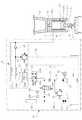
前記流体圧シリンダ13には、該流体圧シリンダ13を伸縮作動させる油圧ユニット等の流体圧ユニット14が接続されている。前記流体圧ユニット14は、油等の作動流体が貯留されたタンク15から延びる圧送ライン16と、流体圧シリンダ13のキャップ側室13a(ピストンロッド13cが突出していない側の室)に接続されるキャップ側ライン17と、流体圧シリンダ13のロッド側室13b(ピストンロッド13cが突出している側の室)に接続されるロッド側ライン18と、前記タンク15へ通じる戻しライン19とを備えている。前記圧送ライン16途中には、モータ20にて駆動されるポンプ21と、該ポンプ21にて圧送される作動流体の逆流を阻止する逆止弁22とが設けられている。前記圧送ライン16及び戻しライン19と、前記キャップ側ライン17とは、ソレノイドバルブ23と減圧切換機構50とを介して接続され、前記圧送ライン16及び戻しライン19と、前記ロッド側ライン18とは、ソレノイドバルブ23を介して接続され、前記逆止弁22とソレノイドバルブ23との間における圧送ライン16途中から分岐させた蓄圧ライン24には、アキュムレータ25が接続されている。 A
前記ソレノイドバルブ23は、ブレーキ作動ポジション23Aとブレーキ解除ポジション23Bとを有している。前記ブレーキ作動ポジション23Aは、前記圧送ライン16とキャップ側ライン17とを前記減圧切換機構50を介して連通させることにより、前記ポンプ21によって圧送される作動流体を流体圧シリンダ13のキャップ側室13aへ導入しつつ、前記ロッド側ライン18と戻しライン19とを連通させることにより、前記流体圧シリンダ13のロッド側室13bの作動流体をタンク15へ排出するポジションである。前記ブレーキ解除ポジション23Bは、前記圧送ライン16とロッド側ライン18とを連通させることにより、前記ポンプ21によって圧送される作動流体を前記流体圧シリンダ13のロッド側室13bへ導入しつつ、前記キャップ側ライン17と戻しライン19とを前記減圧切換機構50を介して連通させることにより、前記流体圧シリンダ13のキャップ側室13aの作動流体をタンク15へ排出するポジションである。尚、ソレノイドバルブ23は、非常停止時(緊急を要する意図的な電源遮断時)及び停電時にはソレノイドへの通電が停止されてバネ力により機械的に前記ブレーキ作動ポジション23Aに切り換わるようになっている。 The
前記ポンプ21と逆止弁22との間における圧送ライン16途中には、前記タンク15へ通じるリリーフライン26が分岐接続され、該リリーフライン26途中には、前記圧送ライン16における作動流体の圧力が設定圧以上となった際に開いて作動流体をタンク15へ戻すリリーフ弁27が設けられている。 A
前記蓄圧ライン24途中には、該蓄圧ライン24における作動流体の圧力が高位設定圧に達した際に作動する高位圧力スイッチ28Hと、前記蓄圧ライン24における作動流体の圧力が低位設定圧に達した際に作動する低位圧力スイッチ28Lと、常時開(ノーマルオープン)で且つ前記高位圧力スイッチ28Hの作動時に閉となるシャットオフ弁28Vとが設けられている。これにより、前記蓄圧ライン24における作動流体の圧力が前記アキュムレータ25の設定圧に達した際には高位圧力スイッチ28Hが作動して前記ポンプ21のモータ20に対し、図示していない制御装置から停止指令が出力されると共に前記シャットオフ弁28Vが閉じる一方、前記圧力が前記アキュムレータ25の設定圧以下に低下した際には低位圧力スイッチ28Lが作動して前記ポンプ21のモータ20に対し、前記制御装置から駆動指令が出力されると共に前記シャットオフ弁28Vが開くようになっている。 In the middle of the
尚、前記蓄圧ライン24途中には、メンテナンス時等に前記アキュムレータ25の作動流体をタンク15に抜くためのドレンライン29が接続され、該ドレンライン29には、作業者によって開閉される手動開閉弁30が設けられている。 A
そして、本実施例の場合、前記減圧切換機構50は、通常停止ライン51及び非常停止ライン52と、切換弁53と、減圧ライン54と、圧力調整弁55と、逆止弁56とを備えている。 In the case of this embodiment, the pressure reducing
前記通常停止ライン51及び非常停止ライン52は、前記流体圧シリンダ13を伸長させてブレーキパッド12をレール4に押し付けるための流体圧ユニット14の作動流体の供給流路としてのキャップ側ライン17途中に並列に設けられている。 The
前記切換弁53は、前記ソレノイドバルブ23と通常停止ライン51及び非常停止ライン52との間に設けられ、通常停止ポジション53Dと非常停止ポジション53Eとを有し、図示していない制御装置によって切り換えられるようになっている。前記通常停止ポジション53Dは、前記ソレノイドバルブ23がブレーキ作動ポジション23Aにあるときには、前記圧送ライン16とキャップ側ライン17とを通常停止ライン51を介して連通させることにより、前記ポンプ21によって圧送される作動流体を通常停止ライン51及びキャップ側ライン17を介して流体圧シリンダ13のキャップ側室13aへ導入するポジションである。一方、前記非常停止ポジション53Eは、前記ソレノイドバルブ23がブレーキ作動ポジション23Aにあるときには、前記圧送ライン16とキャップ側ライン17とを非常停止ライン52を介して連通させることにより、前記ポンプ21によって圧送される作動流体を非常停止ライン52及びキャップ側ライン17を介して流体圧シリンダ13のキャップ側室13aへ導入するポジションである。尚、前記ソレノイドバルブ23がブレーキ解除ポジション23Bにあるときには、前記切換弁53が通常停止ポジション53D或いは非常停止ポジション53Eのいずれのポジションにあっても、キャップ側ライン17と戻しライン19とを非常停止ライン52を介して連通させることにより、前記流体圧シリンダ13のキャップ側室13aの作動流体をキャップ側ライン17及び非常停止ライン52を介してタンク15へ排出するようになっている。又、前記切換弁53は、非常停止時(緊急を要する意図的な電源遮断時)及び停電時にはソレノイドへの通電が停止されてバネ力により機械的に前記非常停止ポジション53Eに切り換わるようになっている。 The switching
前記減圧ライン54は、前記通常停止ライン51途中から分岐してタンク15へ通じるラインである。 The
前記圧力調整弁55は、前記減圧ライン54途中に設けられており、リリーフ弁又は減圧弁とすることができる。 The
前記逆止弁56は、前記通常停止ライン51の減圧ライン54分岐点より下流側に設けられており、前記切換弁53側から流体圧シリンダ13側への作動流体の流れのみを許容して逆流を阻止するようになっている。 The
これにより、前記減圧切換機構50は、通常停止時には流体圧シリンダ13へ導入される作動流体の一部を逃して設定圧まで下げ、非常停止時にのみ流体圧シリンダ13へ作動流体を直接導入するようになっている。 As a result, the
次に、上記実施例の作用を説明する。 Next, the operation of the above embodiment will be described.
図2に示す如く、流体圧ユニット14のソレノイドバルブ23をブレーキ作動ポジション23Aに切り換えた状態にすると、圧送ライン16とキャップ側ライン17とが減圧切換機構50を介して連通することにより、ポンプ21によって圧送される作動流体が流体圧シリンダ13のキャップ側室13aへ導入されつつ、ロッド側ライン18と戻しライン19とが連通することにより、前記流体圧シリンダ13のロッド側室13bの作動流体がタンク15へ排出される。これにより、ピストンロッド13cが流体圧シリンダ13から突出する方向へ移動し、ブレーキパッド12がレール4の走行車輪転動面4aに押し付けられて制動が行われる。 As shown in FIG. 2, when the
ここで、通常停止時には、前記減圧切換機構50の切換弁53は、図示していない制御装置により通常停止ポジション53Dに切り換えられているため、前記流体圧シリンダ13へ導入される作動流体の圧力が設定圧を超えている場合、圧力調整弁55により作動流体の一部が減圧ライン54からタンク15へ逃され、流体圧シリンダ13へ導入される作動流体の圧力は設定圧まで下げられる。 Here, at the time of normal stop, the switching
これにより、本実施例の場合、特許文献2に開示された制動装置とは異なり、停止時に常に最大の力でブレーキパッド12をレール4の走行車輪転動面4aに押し付けるのではなく、通常停止時には作動流体の圧力が抑えられるため、多大な負荷をレール4及び基礎に掛けてしまうことがなくなり、該レール4及び基礎の変形や破損が発生しにくくなると共に、設備全体の寿命が長くなる。 As a result, in the case of this embodiment, unlike the braking device disclosed in
但し、非常停止時には、前記減圧切換機構50の切換弁53は、図示していない制御装置により非常停止ポジション53Eに切り換えられるため、ポンプ21によって圧送される作動流体は、非常停止ライン52及びキャップ側ライン17を通過して流体圧シリンダ13のキャップ側室13aへ導入される。これにより、減圧ライン54へ作動流体が逃されることはなく、キャップ側ライン17から流体圧シリンダ13のキャップ側室13aへ流入する作動流体の圧力が通常停止時に比べ高くなって、ブレーキパッド12がレール4の走行車輪転動面4aに強く押し付けられ、大きな制動力が得られる。このため、非常停止に支障を来たす心配はない。因みに、前記通常停止ライン51の減圧ライン54分岐点より下流側には逆止弁56が設けられているため、非常停止時に非常停止ライン52を流れる作動流体の一部が通常停止ライン51へ逆流して減圧ライン54からタンク15へ逃げてしまうこともない。 However, at the time of emergency stop, the switching
一方、図2に示す状態から、流体圧ユニット14のソレノイドバルブ23をブレーキ解除ポジション23Bに切り換えると、圧送ライン16とロッド側ライン18とが連通することにより、ポンプ21によって圧送される作動流体が流体圧シリンダ13のロッド側室13bへ導入されつつ、キャップ側ライン17と戻しライン19とが連通することにより、流体圧シリンダ13のキャップ側室13aの作動流体がタンク15へ排出される。これにより、ピストンロッド13cが流体圧シリンダ13の内部に収縮する方向へ移動し、ブレーキパッド12がレール4の走行車輪転動面4aから離反して制動が解除され、コンテナクレーン1を走行させることが可能となる。ここで、前記ソレノイドバルブ23がブレーキ解除ポジション23Bに切り換えられたときには、前記切換弁53が通常停止ポジション53D或いは非常停止ポジション53Eのいずれのポジションにあっても、キャップ側ライン17と戻しライン19は、逆止弁56が設けられた通常停止ライン51ではなく非常停止ライン52を介して連通することにより、前記流体圧シリンダ13のキャップ側室13aの作動流体がキャップ側ライン17及び非常停止ライン52を介してタンク15へ排出される形となる。 On the other hand, when the
尚、レール4の走行車輪転動面4aに対し直交する方向へブレーキパッド12を押付・離反自在な流体圧シリンダ13を採用したことにより、前記レール4の走行車輪転動面4aが完全に水平ではなくうねっていても、ブレーキ作動に皿バネを使用した従来のブレーキアクチュエータとは異なり、ストロークを充分に長く取ることができる。このため、うねりに伴って凹んだ箇所でもブレーキパッド12をレール4の走行車輪転動面4aに強く押し付けることが可能となり、均一なブレーキ力が得られる。又、制動装置を取り付けているクレーン本体5が弾性変形しても、ブレーキパッド12はレール4の走行車輪転動面4aに強く押し付けられるため、制動力が低下せず安定する。 By adopting the
又、前記蓄圧ライン24における作動流体の圧力が前記アキュムレータ25の高位設定圧に達した際には高位圧力スイッチ28Hが作動して、前記ポンプ21のモータ20に対し、図示していない制御装置から停止指令が出力されると共にシャットオフ弁28Vが閉じる。一方、前記圧力が前記アキュムレータ25の低位設定圧以下に低下した際には低位圧力スイッチ28Lが作動して、前記ポンプ21のモータ20に対し、前記制御装置から駆動指令が出力されると共に前記シャットオフ弁28Vが開く。これにより、前記アキュムレータ25は常時、高位設定圧と低位設定圧との間の圧力に蓄圧される。しかも、前記ソレノイドバルブ23は、非常停止時及び停電時にはソレノイドへの通電が停止されてバネ力により機械的に前記ブレーキ作動ポジション23Aに切り換わると共に、前記切換弁53も非常停止時及び停電時にはソレノイドへの通電が停止されてバネ力により機械的に前記非常停止ポジション53Eに切り換わるようになっている。又、前記シャットオフ弁28Vは、常時開(ノーマルオープン)であって非常停止時及び停電時には開いている。このため、非常停止時及び停電時には、前記アキュムレータ25に蓄圧された作動流体が蓄圧ライン24から非常停止ライン52及びキャップ側ライン17を介し前記流体圧シリンダ13のキャップ側室13aへ導かれて前記ブレーキパッド12がレール4の走行車輪転動面4aに押し付けられる。この結果、非常停止時及び停電時にたとえポンプ21が停止したとしても、ブレーキを作動させることが可能となる。 Further, when the pressure of the working fluid in the
こうして、非常停止時以外はレール4及び基礎への負荷を緩和することができ、設備全体の寿命延長を図り得る。 In this way, the load on the
尚、本発明の軌道走行式機械の制動装置は、上述の実施例にのみ限定されるものではなく、本発明の要旨を逸脱しない範囲内において種々変更を加え得ることは勿論である。 The braking device for the track-traveling machine of the present invention is not limited to the above-described embodiment, and it goes without saying that various modifications can be made without departing from the gist of the present invention.
1 コンテナクレーン(軌道走行式機械)
4 レール
4a 走行車輪転動面
7 走行車輪
8 走行装置
12 ブレーキパッド
13 流体圧シリンダ
14 流体圧ユニット
15 タンク
17 キャップ側ライン(供給流路)
50 減圧切換機構
51 通常停止ライン
52 非常停止ライン
53 切換弁
54 減圧ライン
55 圧力調整弁
56 逆止弁1 Container crane (orbital traveling machine)
4
50 Pressure reducing
Claims (2)
Translated fromJapanese前記レールの走行車輪転動面に対し該レールと直交する方向へブレーキパッドを押付・離反自在な流体圧シリンダと、
該流体圧シリンダへ作動流体を給排することにより前記流体圧シリンダを伸縮作動させる流体圧ユニットと
を備えた軌道走行式機械の制動装置において、
通常停止時には流体圧シリンダへ導入される作動流体の一部を逃して設定圧まで下げ、非常停止時にのみ流体圧シリンダへ作動流体を直接導入する減圧切換機構を備えたことを特徴とする軌道走行式機械の制動装置。A traveling device in which traveling wheels that can roll along the rails are arranged, and
A fluid pressure cylinder that allows the brake pads to be pressed and separated from the rolling surface of the traveling wheels of the rail in a direction orthogonal to the rail.
In a braking device for a track-traveling machine provided with a fluid pressure unit that expands and contracts the fluid pressure cylinder by supplying and discharging a working fluid to the fluid pressure cylinder.
It is characterized by having a decompression switching mechanism that allows a part of the working fluid introduced into the fluid pressure cylinder to escape to the set pressure at the time of normal stop and directly introduces the working fluid to the fluid pressure cylinder only at the time of emergency stop. Braking device for type machines.
前記流体圧シリンダを伸長させてブレーキパッドをレールに押し付けるための流体圧ユニットの作動流体の供給流路途中に並列に設けられる通常停止ライン及び非常停止ラインと、
通常停止時には作動流体を通常停止ラインへ導入し、非常停止時には作動流体を非常停止ラインへ導入する切換弁と、
前記通常停止ライン途中から分岐してタンクへ通じる減圧ラインと、
該減圧ライン途中に設けられた圧力調整弁と、
前記通常停止ラインの減圧ライン分岐点より下流側に設けられ且つ前記切換弁側から流体圧シリンダ側への作動流体の流れのみを許容して逆流を阻止する逆止弁と
を備えた請求項1記載の軌道走行式機械の制動装置。The decompression switching mechanism is
A normal stop line and an emergency stop line provided in parallel in the working fluid supply flow path of the fluid pressure unit for extending the fluid pressure cylinder and pressing the brake pad against the rail.
A switching valve that introduces the working fluid to the normal stop line at the time of normal stop and introduces the working fluid to the emergency stop line at the time of emergency stop.
A decompression line that branches off from the middle of the normal stop line and leads to the tank,
A pressure regulating valve provided in the middle of the pressure reducing line and
Claim 1 is provided with a check valve provided on the downstream side of the decompression line branch point of the normal stop line and which allows only the flow of the working fluid from the switching valve side to the fluid pressure cylinder side and prevents the backflow. The braking device for the orbital traveling machine described.
Priority Applications (1)
| Application Number | Priority Date | Filing Date | Title |
|---|---|---|---|
| JP2017089204AJP6840614B2 (en) | 2017-04-28 | 2017-04-28 | Braking device for orbital machinery |
Applications Claiming Priority (1)
| Application Number | Priority Date | Filing Date | Title |
|---|---|---|---|
| JP2017089204AJP6840614B2 (en) | 2017-04-28 | 2017-04-28 | Braking device for orbital machinery |
Publications (2)
| Publication Number | Publication Date |
|---|---|
| JP2018187951A JP2018187951A (en) | 2018-11-29 |
| JP6840614B2true JP6840614B2 (en) | 2021-03-10 |
Family
ID=64479374
Family Applications (1)
| Application Number | Title | Priority Date | Filing Date |
|---|---|---|---|
| JP2017089204AActiveJP6840614B2 (en) | 2017-04-28 | 2017-04-28 | Braking device for orbital machinery |
Country Status (1)
| Country | Link |
|---|---|
| JP (1) | JP6840614B2 (en) |
Families Citing this family (1)
| Publication number | Priority date | Publication date | Assignee | Title |
|---|---|---|---|---|
| KR20130130871A (en)* | 2007-05-21 | 2013-12-02 | 이 잉크 코포레이션 | Methods for driving video electro-optic displays |
Family Cites Families (7)
| Publication number | Priority date | Publication date | Assignee | Title |
|---|---|---|---|---|
| US4308937A (en)* | 1979-12-04 | 1982-01-05 | Johnson Norman A | Self-aligning clamping apparatus |
| JP3209288B2 (en)* | 1992-07-29 | 2001-09-17 | 財団法人鉄道総合技術研究所 | Brake equipment for railway vehicles |
| JPH09315121A (en)* | 1996-05-28 | 1997-12-09 | Nissei Kk | Brake control device for railroad vehicle |
| DE10029889A1 (en)* | 2000-06-19 | 2002-01-03 | Atecs Mannesmann Ag | Braking device for a traveling crane that can be moved on rails |
| JP2002079926A (en)* | 2000-09-08 | 2002-03-19 | Tcm Corp | Industrial vehicle |
| JP6160865B2 (en)* | 2013-09-19 | 2017-07-12 | Jfeエンジニアリング株式会社 | Rail brake device for rail travel type crane |
| JP6211362B2 (en)* | 2013-09-26 | 2017-10-11 | Ihi運搬機械株式会社 | Emergency brake system for track-type machine |
- 2017
- 2017-04-28JPJP2017089204Apatent/JP6840614B2/enactiveActive
Also Published As
| Publication number | Publication date |
|---|---|
| JP2018187951A (en) | 2018-11-29 |
Similar Documents
| Publication | Publication Date | Title |
|---|---|---|
| JP6211362B2 (en) | Emergency brake system for track-type machine | |
| JP6160865B2 (en) | Rail brake device for rail travel type crane | |
| JP6882123B2 (en) | Braking device for orbital machinery | |
| JP7028711B2 (en) | Braking device for track-running machines | |
| JP6986953B2 (en) | Braking device for track-running machines | |
| JP6806449B2 (en) | Braking device for orbital machinery | |
| JP6840614B2 (en) | Braking device for orbital machinery | |
| JP6840608B2 (en) | Braking device for orbital machinery | |
| JP4739251B2 (en) | Cable car start control device | |
| JP6792948B2 (en) | Braking device for orbital machinery | |
| US20120313062A1 (en) | Crash barrier with over-pressure relief system | |
| JP6899704B2 (en) | Rail clamp device for orbital traveling machines | |
| JP6876525B2 (en) | Braking device for orbital machinery | |
| JP2017144954A (en) | Braking device for track traveling type machine | |
| JP6886894B2 (en) | Braking device for orbital machinery | |
| JP6931576B2 (en) | Orbital traveling machine | |
| JP7042070B2 (en) | Braking device for orbiting machines | |
| JP2021035880A (en) | Brake device for track running machine | |
| JP7075745B2 (en) | Braking device for orbiting machines | |
| JP6976104B2 (en) | A fluid pressure actuator and a braking device for a track-traveling machine equipped with the fluid pressure actuator. | |
| KR101889103B1 (en) | Cabin door opening/closing system for Construction Equipment | |
| CN216034305U (en) | Brake control system and have its rail vehicle | |
| JP2015054548A (en) | Wing door switchgear of wing vehicle | |
| JP2018203429A (en) | Rail clamp device for track travel type machine | |
| NO347845B1 (en) | Braking system for hoist games |
Legal Events
| Date | Code | Title | Description |
|---|---|---|---|
| A621 | Written request for application examination | Free format text:JAPANESE INTERMEDIATE CODE: A621 Effective date:20200302 | |
| A977 | Report on retrieval | Free format text:JAPANESE INTERMEDIATE CODE: A971007 Effective date:20210129 | |
| TRDD | Decision of grant or rejection written | ||
| A01 | Written decision to grant a patent or to grant a registration (utility model) | Free format text:JAPANESE INTERMEDIATE CODE: A01 Effective date:20210209 | |
| A61 | First payment of annual fees (during grant procedure) | Free format text:JAPANESE INTERMEDIATE CODE: A61 Effective date:20210217 | |
| R150 | Certificate of patent or registration of utility model | Ref document number:6840614 Country of ref document:JP Free format text:JAPANESE INTERMEDIATE CODE: R150 | |
| R250 | Receipt of annual fees | Free format text:JAPANESE INTERMEDIATE CODE: R250 | |
| R250 | Receipt of annual fees | Free format text:JAPANESE INTERMEDIATE CODE: R250 | |
| S111 | Request for change of ownership or part of ownership | Free format text:JAPANESE INTERMEDIATE CODE: R313111 |