Movatterモバイル変換


[0]ホーム

URL:


JP6837977B2 - refrigerator - Google Patents

refrigerator
Download PDF

Info

Publication number
JP6837977B2
JP6837977B2JP2017538331AJP2017538331AJP6837977B2JP 6837977 B2JP6837977 B2JP 6837977B2JP 2017538331 AJP2017538331 AJP 2017538331AJP 2017538331 AJP2017538331 AJP 2017538331AJP 6837977 B2JP6837977 B2JP 6837977B2
Authority
JP
Japan
Prior art keywords
shelf
unit
light source
receiving unit
refrigerator
Prior art date
Legal status (The legal status is an assumption and is not a legal conclusion. Google has not performed a legal analysis and makes no representation as to the accuracy of the status listed.)
Active
Application number
JP2017538331A
Other languages
Japanese (ja)
Other versions
JP2019502080A (en
Inventor
ソンフン リ
ソンフン リ
ピョンサン チョン
ピョンサン チョン
ファンヨン キム
ファンヨン キム
ソンチェ パク
ソンチェ パク
サントゥ ハ
サントゥ ハ
ヨンチュン ソン
ヨンチュン ソン
ソンウク パク
ソンウク パク
チェスン ヤン
チェスン ヤン
ウォンポク リ
ウォンポク リ
キョチョル チェ
キョチョル チェ
チュンキル チョン
チュンキル チョン
Current Assignee (The listed assignees may be inaccurate. Google has not performed a legal analysis and makes no representation or warranty as to the accuracy of the list.)
LG Electronics Inc
Original Assignee
LG Electronics Inc
Priority date (The priority date is an assumption and is not a legal conclusion. Google has not performed a legal analysis and makes no representation as to the accuracy of the date listed.)
Filing date
Publication date
Application filed by LG Electronics IncfiledCriticalLG Electronics Inc
Publication of JP2019502080ApublicationCriticalpatent/JP2019502080A/en
Application grantedgrantedCritical
Publication of JP6837977B2publicationCriticalpatent/JP6837977B2/en
Activelegal-statusCriticalCurrent
Anticipated expirationlegal-statusCritical

Links

Images

Classifications

Landscapes

Description

Translated fromJapanese

本出願は、冷蔵庫に関し、より詳しくは上記冷蔵庫内に取り付けられる棚に関する。 The present application relates to a refrigerator, and more particularly to a shelf mounted in the refrigerator.

一般に、冷蔵庫は食品を新鮮に貯蔵するように構成された装置である。上記冷蔵庫は本体の下部に機械室を含む。上記機械室は、冷蔵庫の重心(質量中心)(center of gravity)を考慮して、かつ組立ての効率(効用性)(efficiency)及び振動低減のために、冷蔵庫の下部に取り付けられることが一般的である。このような冷蔵庫の機械室には冷凍サイクル装置が取り付けられ、低圧の液相冷媒(液状冷媒)(liquid-phase refrigerant)が気相冷媒(気状冷媒)(gas-phase refrigerant)に変化しながら外部の熱を吸収する性質を用いて冷蔵庫の内部を冷凍/冷蔵状態で維持することによって食品を新鮮に保管するようになる。 Generally, a refrigerator is a device configured to store food fresh. The refrigerator includes a machine room at the bottom of the main body. The machine room is generally installed at the bottom of the refrigerator in consideration of the center of gravity of the refrigerator and for the efficiency of assembly and reduction of vibration. Is. A refrigeration cycle device is installed in the machine room of such a refrigerator, and the low-pressure liquid-phase refrigerant is changed to a gas-phase refrigerant. By keeping the inside of the refrigerator in a frozen / refrigerated state by using the property of absorbing external heat, the food can be stored fresh.

上記冷蔵庫の冷凍サイクル装置は、低温低圧の気相冷媒を高温高圧の気相冷媒に変化させる圧縮器と、上記圧縮器で変化させられた高温高圧の気相冷媒を高温高圧の液相冷媒に変化させる凝縮器と、上記凝縮器で変化させられた低温高圧の液相冷媒を気体状(気状)に変化させながら外部の熱を吸収する蒸発器などで構成される。 The refrigerating cycle device of the refrigerator uses a compressor that changes a low-temperature low-pressure gas-phase refrigerant into a high-temperature and high-pressure gas-phase refrigerant, and a high-temperature and high-pressure gas-phase refrigerant changed by the compressor into a high-temperature and high-pressure liquid-phase refrigerant. It is composed of a condenser that changes the refrigerant and an evaporator that absorbs external heat while changing the low-temperature and high-pressure liquid-phase refrigerant changed by the condenser into a gaseous state (gas state).

このような冷蔵庫の内部空間は暗いから、使用者が貯蔵された食品を容易に捜すために、内部空間に照明を提供することができる。しかし、一般に光源が内部空間の特定位置に取り付けられるため、内部空間の全体を照明しにくいことがある。一方、上記冷蔵庫は、内部空間内に取り付けられて食品を支持するように構成される棚を有することができる。一般に、複数(多数)の(a plurality of)棚が内部空間内に取り付けられるので、このような棚に光源を提供すれば、内部空間を均一に照明することができる。したがって、均一な照明のために、内部空間を照明するように上記棚を改良することを考慮する必要がある。 Since the interior space of such a refrigerator is dark, it is possible to provide lighting to the interior space so that the user can easily search for stored food. However, since the light source is generally attached to a specific position in the internal space, it may be difficult to illuminate the entire internal space. On the other hand, the refrigerator can have shelves mounted in the interior space to support food. Generally, a plurality of shelves are installed in the interior space, and if a light source is provided to such shelves, the interior space can be uniformly illuminated. Therefore, it is necessary to consider modifying the shelves to illuminate the interior space for uniform lighting.

本出願は、上記のような問題点を解決するためのもので、本出願の目的は冷蔵庫の内部空間を均一に照明するように構成される冷蔵庫を提供することである。 The present application is to solve the above-mentioned problems, and an object of the present application is to provide a refrigerator configured to uniformly illuminate the internal space of the refrigerator.

また、本出願の目的は内部空間を照明するように構成される棚を有する冷蔵庫を提供することである。 It is also an object of the present application to provide a refrigerator having shelves configured to illuminate the interior space.

目的を達成するための本出願の一態様によると、本出願は、所定大きさの貯蔵室を有するキャビネットと、貯蔵室内に取り付けられ、貯蔵室内を照明するように構成された光源部を有する棚と、外部電源と接続(連結)され(connected to)、無線で電力を伝送する(送る、送信する)(transmit)ように構成され、所定範囲の1次(primary)共振周波数を有する送信部と、送信部から無線で電力を受信して棚の光源部に供給するように構成される受信部と、を有してなり、送信部は、受信部が送信部に近接して配置されるときに発生する2次(secondary)共振周波数を用いて受信部に電力を伝送する冷蔵庫を提供することができる。 According to one aspect of the present application for achieving an object, the present application is a cabinet having a storage chamber of a predetermined size and a shelf having a light source unit mounted in the storage chamber and configured to illuminate the storage chamber. And a transmitter that is connected to an external power source, is configured to transmit power wirelessly, and has a primary resonance frequency within a predetermined range. , A receiver configured to wirelessly receive power from the transmitter and supply it to the light source on the shelf, the transmitter when the receiver is placed close to the transmitter. It is possible to provide a refrigerator that transmits power to a receiving unit by using a secondary resonance frequency generated in the above.

2次共振周波数は1次共振周波数より大きく設定できる。より詳しくは、2次共振周波数は1次共振周波数の2倍より大きく設定できる。1次共振周波数は100〜150kHzの範囲を有し、2次共振周波数は300〜400kHzの範囲を有することができる。 The secondary resonance frequency can be set higher than the primary resonance frequency. More specifically, the secondary resonance frequency can be set to be larger than twice the primary resonance frequency. The primary resonance frequency can have a range of 100 to 150 kHz, and the secondary resonance frequency can have a range of 300 to 400 kHz.

受信部は、2次共振周波数を生成するために、光源部の負荷の抵抗によって負荷に接続されるコンデンサの容量を調節するように構成されることができる。より詳しくは、受信部は、光源部の負荷の抵抗によって負荷に直列及び/又は並列に接続されるコンデンサを有することができる。 The receiver can be configured to adjust the capacitance of the capacitor connected to the load by the resistance of the load of the light source to generate the secondary resonant frequency. More specifically, the receiver can have capacitors connected in series and / or in parallel with the load by the resistance of the load in the light source.

送信部と受信部とは互いに向き合うように貯蔵室の側壁と棚の側部とにそれぞれ提供されることができる。より詳しくは、棚は、棚部材と棚部材の両側部を支持するように構成されるブラケットとを有し、送信部は貯蔵室の側壁に取り付けられ、受信部は棚の側部に取り付けられることができる。また、受信部はブラケットの後方部に取り付けられることができる。 The transmitter and receiver can be provided on the side walls of the storage chamber and on the sides of the shelves, respectively, so that they face each other. More specifically, the shelf has a shelf member and brackets configured to support both sides of the shelf member, the transmitter is attached to the side wall of the storage chamber and the receiver is attached to the side of the shelf. be able to. Further, the receiving portion can be attached to the rear portion of the bracket.

送信部及び受信部は、漏洩される電磁波(電磁気波)(electromagnetic waves)を遮蔽するように構成される遮蔽部材をそれぞれ有することができる。より詳しくは、送信部は、受信部と向き合う第1表面及び第1表面と対向する第2表面を有し、遮蔽部材は第2表面に付着される(attached)ことができる。受信部は、送信部と向き合う第1表面及び第1表面と対向する第2表面を有し、遮蔽部材は第2表面に付着されることができる。 The transmitting unit and the receiving unit can each have a shielding member configured to shield the leaked electromagnetic waves (electromagnetic waves). More specifically, the transmitting unit has a first surface facing the receiving unit and a second surface facing the first surface, and the shielding member can be attached to the second surface. The receiving unit has a first surface facing the transmitting unit and a second surface facing the first surface, and the shielding member can be attached to the second surface.

送信部は、回路基板と、回路基板の受信部と向き合う表面に形成され、電力伝送のための電磁波を生成するコイルと、回路基板と外部電源とを接続する配線と、を有することができる。また、受信部は、回路基板と、回路基板の送信部と向き合う表面に形成され、送信部から伝達された電磁波から電流を誘導するように構成されるコイルと、回路基板と光源部とを接続し、誘導された電流を供給するように構成される配線と、を有することができる。 The transmitting unit may have a circuit board, a coil formed on a surface facing the receiving unit of the circuit board and generating an electromagnetic wave for power transmission, and a wiring for connecting the circuit board and an external power source. Further, the receiving unit connects the circuit board, a coil formed on the surface of the circuit board facing the transmitting unit and configured to induce a current from the electromagnetic wave transmitted from the transmitting unit, and the circuit board and the light source unit. And can have wiring configured to supply the induced current.

一方、目的を達成するための本出願の他の態様によると、本出願は、所定大きさの貯蔵室を有するキャビネットと、貯蔵室内に取り付けられ、貯蔵室内を照明するように構成された光源部を有する棚と、外部電源と接続され、無線で電力を伝送するように構成される送信部と、送信部から無線で電力を受信して棚の光源部に供給するように構成される受信部と、を有してなり、光源部は、ハウジングとハウジング内に配置されて光を照射するように構成される光源モジュールとを有する、冷蔵庫を提供することができる。 On the other hand, according to another aspect of the present application for achieving the object, the present application is a cabinet having a storage chamber of a predetermined size, and a light source unit attached to the storage chamber and configured to illuminate the storage chamber. A shelf that is connected to an external power source and is configured to transmit power wirelessly, and a receiving unit that is configured to receive power wirelessly from the transmitting unit and supply it to the light source unit of the shelf. And, the light source unit can provide a refrigerator having a housing and a light source module arranged within the housing and configured to irradiate light.

光源部は棚の前方部に配置され、下方に光を照射するように配向されることができる。 The light source portion is located at the front portion of the shelf and can be oriented so as to irradiate light downward.

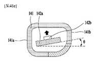
ハウジングは、光を通過させないように構成される遮光部と、光を通過させるように構成されるウィンドウと、を有し、ウィンドウはハウジングの底部の後方部に配置されることができる。ウィンドウの前端と後端との間の距離はハウジングの前端と後端との間の距離の1/2に設定されることができる。また、ウィンドウは曲面状(curved)に形成されることができる。また、光源モジュールは、ハウジングの上部内面に向けて光を照射するように配向されることができる。また、光源モジュールは、ハウジングの上部及び前方内面に向けて光を照射するように、水平面に対して所定角度で傾くように配置されることができる。 The housing has a light-shielding portion that is configured to prevent light from passing through and a window that is configured to allow light to pass through, and the window can be located at the rear of the bottom of the housing. The distance between the front and rear edges of the window can be set to half the distance between the front and rear edges of the housing. Also, the window can be curved. Further, the light source module can be oriented so as to irradiate light toward the upper inner surface of the housing. Further, the light source module can be arranged so as to be tilted at a predetermined angle with respect to the horizontal plane so as to irradiate light toward the upper portion and the front inner surface of the housing.

光源部は光源モジュールを保持するように構成されるホルダを有し、ホルダは、光源モジュールの両端を支持するように構成されるストッパと、光源モジュールの上部及び下部をそれぞれ支持するように構成される第1及び第2アームと、を有することができる。また、第2アームが第1アームより長く伸びる(extends)ことができる。 The light source unit has a holder configured to hold the light source module, and the holder is configured to support both ends of the light source module and the upper and lower portions of the light source module, respectively. The first and second arms can be provided. Also, the second arm can extend longer than the first arm.

棚は物品を支持するように構成され、透明な胴体(body)を有する棚部材を有し、棚部材は、透明な胴体に配置され、胴体を通じて光が漏出することを防止するように構成される不透明なレイヤを有することができる。より詳しくは、レイヤは棚部材の縁部に沿って形成されることができる。 The shelves are configured to support articles and have shelf members with a transparent body, which are arranged on the transparent fuselage to prevent light from leaking through the fuselage. Can have opaque layers. More specifically, the layers can be formed along the edges of the shelf members.

光源部は、棚の直下方に(vertically downward)光を照射するように水平面と平行に配向されるか、あるいは棚の後方部にも光を照射するように水平面に対して所定角度で傾くように配向されることができる。 The light source should be oriented parallel to the horizontal plane to illuminate vertically downward light, or tilted at a predetermined angle with respect to the horizontal plane to illuminate the rear part of the shelf as well. Can be oriented to.

また、目的を達成するための本出願の他の態様によると、本出願は、所定大きさの貯蔵室を有するキャビネットと、貯蔵室内に取り付けられ、貯蔵室内を照明するように構成された光源部を有する棚と、外部電源と接続され、無線で電力を伝送するように構成される送信部と、送信部から無線で電力を受信して棚の光源部に供給するように構成される受信部と、を有してなり、送信部及び受信部の内部には、外部から異物(foreign impurities)がその内部に進入することを防止するシーリング部材が提供される冷蔵庫を提供することができる。 Further, according to another aspect of the present application for achieving the object, the present application includes a cabinet having a storage chamber of a predetermined size, and a light source unit mounted in the storage chamber and configured to illuminate the storage chamber. A shelf that is connected to an external power source and is configured to transmit power wirelessly, and a receiver that is configured to receive power wirelessly from the transmission unit and supply it to the light source unit of the shelf. And, inside the transmitting unit and the receiving unit, it is possible to provide a refrigerator provided with a sealing member for preventing foreign impurities from entering the inside thereof.

光源部は、ハウジングと、ハウジング内に配置され、光を照射するように構成される光源モジュールと、ハウジングの内部に配置され、光源モジュールを保持するホルダと、ハウジングとホルダとの間に挿入(介在)され(interposed)、外部物質(foreign impurities)がハウジング内に進入することを防止する第1シーリング部と、を有することができる。 The light source unit is inserted between the housing, a light source module arranged in the housing and configured to irradiate light, a holder arranged inside the housing and holding the light source module, and the housing and the holder ( It can have a first sealing portion that is interposed and prevents foreign impurities from entering the housing.

また、光源部は、ハウジングの外部に配置され、棚に結合されるヘッドと、ヘッドの内部に提供され、外部物質がハウジング内に進入することを防止する第2シーリング部と、をさらに有することができる。 Further, the light source unit further has a head arranged outside the housing and coupled to the shelf, and a second sealing unit provided inside the head to prevent external substances from entering the housing. Can be done.

また、光源部は、ホルダと光源モジュールとの間に挿入され、外部物質が光源モジュールに到逹することを防止する第3シーリング部をさらに有することができる。 Further, the light source unit may further have a third sealing unit that is inserted between the holder and the light source module to prevent an external substance from reaching the light source module.

冷蔵庫は、受信部を保護するために受信部を覆うように構成されるカバーをさらに有することができ、カバーは無線電力伝送を邪魔しない素材でなることができる。より詳しくは、カバーは非伝導又は非金属素材でなることができる。 Refrigerators can further have a cover configured to cover the receiver to protect the receiver, which can be made of a material that does not interfere with wireless power transfer. More specifically, the cover can be made of non-conducting or non-metallic material.

本出願で説明する例によって、冷蔵庫の棚に光源を提供することによって冷蔵庫の内部空間を均一に照明することができる。また、棚の光源に無線で電力を供給することによって、漏電、感電又は腐食などの問題が発生しない。その上、無線電力伝送のための機械的及び回路的構成が最適に設計され、最適な制御が適用されることによって、冷蔵庫の内部空間をより効果的で効率的に照明することができる。 According to the example described in this application, the interior space of the refrigerator can be uniformly illuminated by providing a light source on the shelf of the refrigerator. Further, by wirelessly supplying electric power to the light source of the shelf, problems such as electric leakage, electric shock or corrosion do not occur. Moreover, by optimally designing the mechanical and circuit configurations for wireless power transfer and applying optimal control, the interior space of the refrigerator can be illuminated more effectively and efficiently.

本出願で説明する例(example)の適用可能性の更なる範囲は以下の詳細な説明から明らかになるであろう。しかし、説明した例の思想及び範囲内の多様な変更及び修正は当業者にとって明らかに理解可能であるので、詳細な説明及び本出願の好適な例はただ例示のために与えられたものとして理解しなければならない。 Further scope of applicability of the examples described in this application will become apparent from the detailed description below. However, since the ideas of the examples described and the various changes and amendments within the scope are clearly understandable to those skilled in the art, detailed explanations and suitable examples of the present application are understood as provided for illustration purposes only. Must.

本出願による冷蔵庫を示す正面図である。It is a front view which shows the refrigerator by this application.本出願の一例(example)による冷蔵庫棚に装着される無線電力伝送システムの回路を概略的に示す概略図である。It is the schematic which shows schematic the circuit of the wireless power transmission system mounted on the refrigerator shelf by an example (example) of this application.本出願の一例による冷蔵庫棚に装着される無線電力伝送システムの回路をより詳細に示すブロック図である。It is a block diagram which shows the circuit of the wireless power transmission system mounted on the refrigerator shelf by an example of this application in more detail.本出願の一例によって実験的に獲得された1次共振、2次共振及び利得(ゲイン)(gain)の関係を示すグラフである。It is a graph which shows the relationship between the primary resonance, the secondary resonance and the gain (gain) experimentally acquired by an example of this application.本出願の一例によって実験的に獲得された1次共振、2次共振及び位相(phase)の関係を示すグラフである。It is a graph which shows the relationship between the primary resonance, the secondary resonance and the phase experimentally acquired by an example of this application.本出願の一例による無線電力伝送システムの送信部の構造を簡略に示す概略図である。It is the schematic which shows the structure of the transmission part of the wireless power transmission system according to the example of this application simply.本出願の一例による無線電力伝送システムの受信部の構造の一例を示す概略図である。It is the schematic which shows an example of the structure of the receiving part of the wireless power transmission system according to the example of this application.本出願の一例による無線電力伝送システムの受信部の構造の他の一例を示す概略図である。It is the schematic which shows another example of the structure of the receiving part of the wireless power transmission system by one example of this application.本出願の一例による無線電力伝送システムの受信部の構造のさらに他の一例を示す概略図である。It is the schematic which shows still another example of the structure of the receiving part of the wireless power transmission system by one example of this application.図11〜図13に示したそれぞれの受信部の構造のための条件を示すテーブルである。It is a table which shows the condition for the structure of each receiving part shown in FIGS. 11 to 13.図10に示した送信部の構造の一例を示す概略図である。It is the schematic which shows an example of the structure of the transmission part shown in FIG.図10に示した送信部の構造の他の一例を示す概略図である。It is the schematic which shows another example of the structure of the transmission part shown in FIG.図10に示した送信部の構造のさらに他の一例を示す概略図である。It is the schematic which shows still another example of the structure of the transmission part shown in FIG.冷蔵庫の貯蔵室及び棚を概略的に示す斜視図である。It is a perspective view which shows typically the storage room and the shelf of a refrigerator.本出願の一例による冷蔵庫の構成を示すブロック図である。It is a block diagram which shows the structure of the refrigerator by an example of this application.本出願による棚を左側から見た斜視図である。It is a perspective view which looked at the shelf by this application from the left side.本出願による棚を右側から見た斜視図である。It is a perspective view which looked at the shelf by this application from the right side.本出願による棚を下部から見た斜視図である。It is a perspective view which looked at the shelf by this application from the bottom.移動された棚部材を有する棚を示す斜視図である。It is a perspective view which shows the shelf which has the moved shelf member.図16の棚の分解斜視図である。It is an exploded perspective view of the shelf of FIG.図16の棚の分解斜視図である。It is an exploded perspective view of the shelf of FIG.カバー、受信部及び送信部を含む棚の部分斜視図である。It is a partial perspective view of the shelf including a cover, a receiving part and a transmitting part.受信部及び光源部のアセンブリを示す平面図である。It is a top view which shows the assembly of a receiving part and a light source part.カバーを詳細に示す平面図である。It is a top view which shows the cover in detail.本出願による冷蔵庫及び棚を示す部分斜視図である。It is a partial perspective view which shows the refrigerator and the shelf by this application.棚のブラケット及び受信部を示す部分平面図である。It is a partial plan view which shows the bracket and the receiving part of a shelf.貯蔵室側壁の送信部と棚の受信部との整列を説明する側面図である。It is a side view explaining the alignment of the transmitting part of the side wall of a storage room, and the receiving part of a shelf.図16aのA−A線に沿って得られた断面図である。It is sectional drawing obtained along the line AA of FIG. 16a.棚の光源部の上部(top)を示す平面図である。It is a top view which shows the upper part (top) of the light source part of a shelf.図25のB−B線に沿って得られた断面図である。It is sectional drawing obtained along the line BB of FIG.図16aのC−C線に沿って得られた断面図である。It is sectional drawing obtained along the line CC of FIG. 16a.前方に光を照射するように構成された棚の光源部を示す斜視図である。It is a perspective view which shows the light source part of the shelf which was configured to irradiate light forward.下方に光を照射するように構成された棚の光源部を示す斜視図である。It is a perspective view which shows the light source part of the shelf which was configured to irradiate light downward.図27の光源部の底部(bottom)を示す平面図である。It is a top view which shows the bottom part (bottom) of the light source part of FIG.ブラケットに結合された(coupled)光源部を示す部分斜視図及び光源部のキャップ部材を詳細に示す部分拡大図である。It is a partial perspective view which shows the (coupled) light source part coupled to a bracket, and the partial enlarged view which shows the cap member of a light source part in detail.ブラケットに結合された光源部を示す部分斜視図である。It is a partial perspective view which shows the light source part coupled to the bracket.送信部の側部を示す側面図である。It is a side view which shows the side part of the transmission part.送信部の背面を示す背面図である。It is a rear view which shows the back of the transmitter.送信部の取付けのための構造を含むインナケースの部分斜視図である。It is a partial perspective view of an inner case including a structure for mounting a transmitter.冷蔵庫に取り付けられた送信部及び受信部の一例を示す部分断面図である。It is a partial cross-sectional view which shows an example of a transmitting part and a receiving part attached to a refrigerator.冷蔵庫に取り付けられた送信部及び受信部の他の例を示す部分断面図である。FIG. 5 is a partial cross-sectional view showing another example of a transmitting unit and a receiving unit attached to a refrigerator.冷蔵庫に取り付けられた送信部を示す部分斜視図である。It is a partial perspective view which shows the transmission part attached to a refrigerator.光源部の右側キャップを示す斜視図である。It is a perspective view which shows the right side cap of a light source part.光源部の左側キャップを示す斜視図である。It is a perspective view which shows the left side cap of a light source part.前記キャップを示す平面図である。It is a top view which shows the cap.前記キャップを示す正面図である。It is a front view which shows the cap.前記キャップを示す右側面図である。It is a right side view which shows the cap.棚部材のレールを示す斜視図及び部分拡大図である。It is a perspective view and a partially enlarged view which shows the rail of a shelf member.冷蔵庫の内部を照明する壁体(wall)の光源を示す冷蔵庫の正面図である。It is a front view of the refrigerator which shows the light source of the wall body (wall) which illuminates the inside of the refrigerator.冷蔵庫の内部を照明する壁体の光源及び棚の光源部を示す冷蔵庫の断面図である。It is sectional drawing of the refrigerator which shows the light source of the wall body which illuminates the inside of the refrigerator, and the light source part of a shelf.光源部の配向(orientation)の例を示す側面図である。It is a side view which shows the example of the orientation (orientation) of a light source part.光源部の配向の例を示す側面図である。It is a side view which shows the example of the orientation of a light source part.光源部のハウジング及び光源モジュールの構成を示す断面図である。It is sectional drawing which shows the structure of the housing of the light source part and the light source module.図41aの構成の他の例を示す断面図である。It is sectional drawing which shows the other example of the structure of FIG. 41a.図41aの構成の他の例を示す断面図である。It is sectional drawing which shows the other example of the structure of FIG. 41a.図41aの構成の他の例を示す断面図である。It is sectional drawing which shows the other example of the structure of FIG. 41a.図41aの構成の他の例を示す断面図である。It is sectional drawing which shows the other example of the structure of FIG. 41a.不透明なレイヤを含む棚部材を示す平面図である。It is a top view which shows the shelf member including an opaque layer.光源部及びブラケットのバー(bar)の多様な配置例を示す側面図である。It is a side view which shows various arrangement examples of a light source part and a bar of a bracket.光源部及びブラケットのバーの多様な配置例を示す側面図である。It is a side view which shows various arrangement examples of a light source part and a bar of a bracket.光源部及びブラケットのバーの多様な配置例を示す側面図である。It is a side view which shows various arrangement examples of a light source part and a bar of a bracket.光源部及びバーの配置に関連した詳細な構成を示す側面図である。It is a side view which shows the detailed structure related to the arrangement of a light source part and a bar.受信部と光源部との電気的接続の変形例を示す斜視図である。It is a perspective view which shows the modification of the electrical connection between a receiving part and a light source part.貯蔵室の後壁に取り付けられる送信部を示す正面図である。It is a front view which shows the transmission part attached to the rear wall of a storage room.後方部に取り付けられた受信部を有する棚を示す斜視図である。It is a perspective view which shows the shelf which has the receiving part attached to the rear part.貯蔵室の側壁に支持される棚において送信部及び受信部の構成を示す正面図である。It is a front view which shows the structure of the transmitting part and the receiving part in the shelf supported by the side wall of a storage chamber.図48の棚を示す背面図である。It is a rear view which shows the shelf of FIG. 48.貯蔵室の側壁に支持される棚において送信部及び受信部の構成の他の例を示す正面図である。FIG. 5 is a front view showing another example of the configuration of a transmitting unit and a receiving unit in a shelf supported by a side wall of a storage chamber.図50の棚を示す側面図である。It is a side view which shows the shelf of FIG.送信部の基板及びコイルの詳細な構成を示す平面図である。It is a top view which shows the detailed structure of the substrate and the coil of a transmission part.受信部の基板及びコイルの詳細な構成を示す平面図である。It is a top view which shows the detailed structure of the substrate and the coil of a receiving part.ドアが開くときの光源を制御する方法を示すフローチャートである。It is a flowchart which shows the method of controlling the light source when a door opens.ドアが閉まるときの光源を制御する方法を示すフローチャートである。It is a flowchart which shows the method of controlling the light source when a door closes.

一般に、冷蔵庫は、内部が断熱材で充填されたキャビネット及びドアによって、外部から浸透する熱を遮断することができる食品貯蔵空間をなし、上記食品貯蔵空間の内部の熱を吸収する蒸発器と収集された熱を上記食品貯蔵空間の外部に排出する放熱装置とで構成された冷凍装置を備え、上記食品貯蔵空間を微生物の生存及び増殖が難しい低温領域で維持し、貯蔵された食品を長期間にわたって変質なしで保管する装置である。 Generally, a refrigerator forms a food storage space in which heat penetrating from the outside can be blocked by a cabinet and a door whose inside is filled with a heat insulating material, and an evaporator and a collector for absorbing heat inside the food storage space. It is equipped with a refrigerating device composed of a heat radiating device that discharges the generated heat to the outside of the food storage space, maintains the food storage space in a low temperature region where it is difficult for microorganisms to survive and grow, and keeps the stored food for a long period of time. It is a device that stores without deterioration over time.

上記冷蔵庫は、零度以上の温度領域で食品を貯蔵する冷蔵室と零下の温度領域で食品を貯蔵する冷凍室とに分離して形成され、上記冷蔵室及び冷凍室の配置によって、上部冷凍室及び下部冷蔵室を配置したトップフリーザ(Top Freezer)冷蔵庫、下部冷凍室及び上部冷蔵室を配置したボトムフリーザ(Bottom Freezer)冷蔵庫、左側冷凍室及び右側冷蔵室を配置したサイドバイサイド(Side by side)冷蔵庫などに分類される。そして、使用者が上記食品貯蔵空間に貯蔵された食品を便利に置く(積んでおく)(place)か又は取り出す(引き出す)(retrieve)ため、複数の棚及び引き出しなどを上記食品貯蔵空間の内部に備えている。 The refrigerator is formed separately into a refrigerating chamber for storing food in a temperature region above zero and a freezing chamber for storing food in a temperature region below zero. Top Freezer refrigerator with lower refrigerator, Bottom Freezer refrigerator with lower and upper refrigerators, Side by side refrigerator with left and right refrigerators, etc. are categorized. Then, in order for the user to conveniently place (place) or take out (retrieve) the food stored in the food storage space, a plurality of shelves and drawers are placed inside the food storage space. Be prepared for.

以下、上記の目的を具体的に実現することができる本出願の例(examples)を添付図面に基づいて説明する。 Hereinafter, examples of the present application that can specifically realize the above object will be described with reference to the accompanying drawings.

この過程で図面に示した構成要素の大きさや形状などは説明の明瞭性及び便宜のために誇張して図示されることができる。また、本出願の構成及び作用を考慮して特別に定義された用語は使用者又は運用者の意図又は慣例によって変わることができる。このような用語に対する定義はこの明細書の全般にわたる内容に基づいて行われなければならない。 In this process, the sizes and shapes of the components shown in the drawings can be exaggerated for the sake of clarity and convenience of explanation. In addition, terms specially defined in consideration of the structure and operation of the present application may be changed depending on the intention or custom of the user or the operator. Definitions for such terms shall be based on the general content of this specification.

本明細書で説明する無線電力伝送システムの回路的及び構造的構成は、無線電力送信又は充電が必要などのデバイスにも適用可能である。すなわち、次の詳細な説明では上記無線電力伝送システムの構成を主に冷蔵庫、特に棚に関連して説明するが、必ずしも冷蔵庫に限定されるものではなく、全てのデバイスで電力の無線伝送のために特別な変形なしに使うことができる。例えば、携帯電話、スマートフォン、ノートブック型パソコン、ウェアラブルデバイス、HMD、サイネージ(sign)、スマートウォッチ、スマートガラス、TV、洗濯機、清掃機、エアコンなどに上記無線電力伝送システムの回路的及び構造的構成を直ちに適用することが可能である。したがって、説明された構成を含むどのデバイスでも本願の権利範囲に含まれる。 The circuit and structural configurations of the wireless power transfer system described herein are also applicable to devices that require wireless power transmission or charging. That is, in the following detailed description, the configuration of the wireless power transmission system will be described mainly in relation to the refrigerator, particularly the shelf, but the present invention is not necessarily limited to the refrigerator, and all devices are used for wireless power transmission. Can be used without any special deformation. For example, the circuit and structure of the above wireless power transmission system for mobile phones, smartphones, notebook computers, wearable devices, HMDs, signage (signs), smart watches, smart glasses, TVs, washing machines, cleaners, air conditioners, etc. The configuration can be applied immediately. Therefore, any device containing the described configuration is included in the scope of rights of the present application.

図1は本出願の一例による冷蔵庫の正面図である。 FIG. 1 is a front view of a refrigerator according to an example of the present application.

図1を参照すると、一例による冷蔵庫は外観をなすキャビネット1を含む。 Referring to FIG. 1, the refrigerator according to the example includes acabinet 1 having an appearance.

上記キャビネット1には食品を貯蔵することができる貯蔵室2が備えられる。キャビネット1はインナケース10から所定間隔で離隔して上記インナケース10を取り囲むアウタケース10aを有することができる。また、インナケース10とアウタケース10aとの間の空間は断熱材で満たされることができる。 Thecabinet 1 is provided with astorage room 2 capable of storing food. Thecabinet 1 may have an outer case 10a that surrounds theinner case 10 at predetermined intervals from theinner case 10. Further, the space between theinner case 10 and the outer case 10a can be filled with a heat insulating material.

上記貯蔵室2は上記キャビネット1の内側に備えられるインナケース10によって形成されることができる。上記貯蔵室2は、後方面をなす後壁13、上側面をなす上側壁12、側面をなす二つの側壁15及び底面(背面)(bottom surface)をなす底14を含む。上記貯蔵室2の前面は開放されることにより、使用者が上記貯蔵室2の前面を通して上記貯蔵室に食品を入れるかあるいは上記貯蔵室から食品を取り出すことができる。より詳細には、後壁13はその中央部を中心に左側後壁13a及び右側後壁13bを含むことができる。また、側壁15は左側側壁15a及び右側側壁15bを含むことができる。次の説明で、他の説明がない限り、後壁13は左右側後壁13a、13bを包括し、図面符号13、13a、13bは関連の構成要素の相対的位置によって選択的に使われることができる。同様に、側壁15は左右側側壁15a、15bを包括し、図面符号15、15a、15bは関連の構成要素の相対的位置によって選択的に使われることができる。 Thestorage chamber 2 can be formed by aninner case 10 provided inside thecabinet 1. Thestorage chamber 2 includes arear wall 13 forming a rear surface, anupper side wall 12 forming an upper side surface, twoside walls 15 forming a side surface, and a bottom 14 forming a bottom surface. By opening the front surface of thestorage chamber 2, the user can put food in the storage chamber or take out food from the storage chamber through the front surface of thestorage chamber 2. More specifically, therear wall 13 can include a leftrear wall 13a and a rightrear wall 13b centered on its central portion. Further, theside wall 15 can include aleft side wall 15a and aright side wall 15b. In the following description, unless otherwise stated, therear wall 13 includes the left and rightrear walls 13a, 13b, and drawingreference numerals 13, 13a, 13b are selectively used according to the relative positions of the related components. Can be done. Similarly, theside wall 15 includes the left andright side walls 15a, 15b, and drawingreference numerals 15, 15a, 15b can be selectively used depending on the relative positions of the related components.

上記キャビネット1の前面には、上記キャビネット1に回動可能に取り付けられ、上記貯蔵室2の一側を開閉する第1ドア20と、上記キャビネット1に回動可能に取り付けられ、上記貯蔵室2の他側を開閉する第2ドア40と、が備えられる。この際、上記第1ドア20及び上記第2ドア40が上記貯蔵室2の前面を閉鎖すれば、上記貯蔵室2が全体的に(完全に)(completely)密閉されることができる。 On the front surface of thecabinet 1, afirst door 20 that is rotatably attached to thecabinet 1 and opens and closes one side of thestorage chamber 2 and afirst door 20 that is rotatably attached to thecabinet 1 and is rotatably attached to thestorage chamber 2. Asecond door 40 that opens and closes the other side is provided. At this time, if thefirst door 20 and thesecond door 40 close the front surface of thestorage chamber 2, thestorage chamber 2 can be completely (completely) sealed.

上記第1ドア20には、上記第2ドア40に接触することができるように回転するピラー50が備えられることができる。上記ピラー50は全体として(overall shape of)直方体形に形成され、上記第1ドア20に対して回転することができるよう(回転可能)に上記第1ドア20に結合されることができる。 Thefirst door 20 may be provided with apillar 50 that rotates so that it can come into contact with thesecond door 40. Thepillar 50 is formed in an overall shape of rectangular parallelepiped shape and can be coupled to thefirst door 20 so as to be rotatable (rotatable) with respect to thefirst door 20.

上記第1ドア20には上記第1ドア20の後方外観をなすドアダイク(door dike)22が備えられることができる。また、上記第2ドア40にも上記第2ドア40の後方外観をなすドアダイク42が備えられることができる。 Thefirst door 20 may be provided with adoor dike 22 that has a rear appearance of thefirst door 20. Further, thesecond door 40 can also be provided with adoor dike 42 having a rear appearance of thesecond door 40.

上記ドアダイク42、22にはそれぞれバスケット44、24が取り付けられ、それぞれのバスケット44、24には多様な形態の食品が貯蔵されることができる。Baskets 44 and 24 are attached to thedoor dikes 42 and 22, respectively, and various forms of food can be stored in thebaskets 44 and 24, respectively.

上記貯蔵室2には、上記第1ドア20側に配置される第1ドロワ(引出し、ドローア)(drawer)32と上記第2ドア40側に配置される第2ドロワ34とが備えられることができる。この際、上記第1ドロワ32及び上記第2ドロワ34は同じ水平面上に配置されることができる。すなわち、上記第1ドロワ32及び上記第2ドロワ34は、上記貯蔵室2内で同一の高さに、左右側にそれぞれ配置されることが可能である。上記第1ドロワ32と上記第2ドロワ34とはそれぞれ独立して引き出されることができる。 Thestorage chamber 2 may be provided with afirst drawer 32 arranged on thefirst door 20 side and asecond drawer 34 arranged on thesecond door 40 side. it can. At this time, thefirst drawer 32 and thesecond drawer 34 can be arranged on the same horizontal plane. That is, thefirst drawer 32 and thesecond drawer 34 can be arranged on the left and right sides at the same height in thestorage chamber 2, respectively. Thefirst drawer 32 and thesecond drawer 34 can be pulled out independently of each other.

本出願の一例では、単一貯蔵室2の左側部を開閉する上記第1ドア20と右側部を開閉する上記第2ドア40とが備えられるので、単一貯蔵室の左右側がそれぞれのドアによって開閉されることができる。 In one example of the present application, thefirst door 20 that opens and closes the left side portion of thesingle storage chamber 2 and thesecond door 40 that opens and closes the right side portion are provided. It can be opened and closed.

上記貯蔵室2には、その上に食品が載置されることができる棚100が取り付けられることができる。上記棚100は、食品を支持するために、貯蔵室2の内側壁に支持される必要がある。棚100が左右側壁15a、15bによって支持されれば、このような棚100は左側壁15aから右側壁15bまで継続的に伸び、これによって同一高さ又は同一平面上に一つの棚100のみが取り付けられることができる。一方、棚100が後壁13に支持されれば、二つ又はそれ以上の棚100が、図1に示すように、上記貯蔵室2の左右側にそれぞれ配置されることができる。すなわち、複数の棚100が後壁13に支持されて同一平面上に配置されることができる。また、複数の棚100が後壁13又は側壁15に支持され、相異なる高さに配置されることができる。 Ashelf 100 on which food can be placed can be attached to thestorage chamber 2. Theshelf 100 needs to be supported on the inner wall of thestorage chamber 2 in order to support food. If theshelves 100 are supported by the left andright side walls 15a, 15b,such shelves 100 continuously extend from theleft side wall 15a to theright side wall 15b, whereby only oneshelf 100 can be mounted at the same height or on the same plane. Can be On the other hand, if theshelves 100 are supported by therear wall 13, two ormore shelves 100 can be arranged on the left and right sides of thestorage chamber 2 as shown in FIG. That is, a plurality ofshelves 100 can be supported by therear wall 13 and arranged on the same plane. Further, a plurality ofshelves 100 are supported by therear wall 13 or theside wall 15 and can be arranged at different heights.

一方、冷蔵庫の貯蔵室2は暗いから、使用者が貯蔵された食品を容易に捜すためには、内部空間に照明を提供することができる。しかし、一般に、光源は内部空間の特定の位置、例えば上側壁12又は後壁13に取り付けられるため、内部空間の全体を照明しにくいことがあり得る。したがって、上記棚100が貯蔵室2を照明するように構成されることができる。前述したように、複数の棚100が貯蔵室2を分割しながら貯蔵室2内に取り付けられるので、このような棚100に光源を提供すれば、内部空間、つまり貯蔵室2を均一に照明することができる。 On the other hand, since thestorage room 2 of the refrigerator is dark, it is possible to provide lighting to the internal space in order for the user to easily search for the stored food. However, in general, since the light source is attached to a specific position in the interior space, for example, theupper side wall 12 or therear wall 13, it may be difficult to illuminate the entire interior space. Therefore, theshelf 100 can be configured to illuminate thestorage chamber 2. As described above, since a plurality ofshelves 100 are mounted in thestorage chamber 2 while dividing thestorage chamber 2, if a light source is provided to such ashelf 100, the internal space, that is, thestorage chamber 2 is uniformly illuminated. be able to.

棚100が光源又は照明装置を有する場合、このような光源に電源を供給するための装置が必要と(要求)される(required)。このような電源供給装置として、電源光源を配線又は接点を介して直接接続する接続構造を適用することができる。例えば、棚100の所定部位に電源需給接点部を取り付け、冷蔵庫の所定部位、つまり貯蔵室2の壁12〜15のいずれか一つには電源供給接点部を取り付けることができる。また、棚が貯蔵室2の壁12〜15のいずれか一つに取り付けられれば、電源需給接点部と電源供給接点部とが互いに接続されることができる。したがって、電源が供給されれば、棚100の光源は光を発散することができる。しかし、このような直結式構造では、冷蔵庫そのものの多湿な環境によって、棚及び冷蔵庫本体のそれぞれの露出した(導出された)(exposed)接点部が腐食されるか機械的接触不良を引き起こす可能性が非常に高い。その上、冷蔵庫の内部に保管された液体の管理不良によって又は棚洗浄後の結合過程で接点部の漏水又は感電の可能性も非常に高い。 If theshelf 100 has a light source or lighting device, a device for supplying power to such a light source is required. As such a power supply device, a connection structure in which a power source light source is directly connected via wiring or contacts can be applied. For example, a power supply / supply contact portion can be attached to a predetermined portion of theshelf 100, and a power supply contact portion can be attached to a predetermined portion of the refrigerator, that is, any one of thewalls 12 to 15 of thestorage chamber 2. Further, if the shelf is attached to any one of thewalls 12 to 15 of thestorage chamber 2, the power supply / supply contact portion and the power supply / supply contact portion can be connected to each other. Therefore, if power is supplied, the light source on theshelf 100 can radiate light. However, in such a direct connection structure, the humid environment of the refrigerator itself may corrode the exposed (exposed) contacts of the shelves and the refrigerator body, or cause poor mechanical contact. Is very high. Moreover, there is a very high possibility of water leakage or electric shock at the contacts due to poor management of the liquid stored inside the refrigerator or during the coupling process after shelf cleaning.

一方、鎖交磁束(Magnetic flux)を用いる無線電力伝送技術が近年に論議されており、モバイル機器だけでなく電気自動車の無線充電の分野でも商業化するように技術開発が論議されている。特に、後述するように、このような無線電力伝送技術は磁束を用いて配線なしで電力を伝送することができるので、着脱が必要とされるか、防水機能が必要とされるかあるいは防塵機能が必要とされる装置に有用になることができる。したがって、棚100は、貯蔵室2を照明するための光源を有するように構成し、かつこのような光源に電力を供給するために、無線電力伝送システムを用いることができる。 On the other hand, wireless power transmission technology using magnetic flux has been discussed in recent years, and technological development has been discussed so as to be commercialized not only in mobile devices but also in the field of wireless charging of electric vehicles. In particular, as will be described later, such wireless power transmission technology can transmit power using magnetic flux without wiring, so that it is necessary to attach / detach it, a waterproof function is required, or a dustproof function. Can be useful for devices that require. Therefore, theshelf 100 is configured to have a light source for illuminating thestorage chamber 2, and a wireless power transmission system can be used to supply power to such a light source.

図2は、本出願の一例による冷蔵庫棚に装着される無線電力伝送システムの回路を概略的に示している。 FIG. 2 schematically shows a circuit of a wireless power transmission system mounted on a refrigerator shelf according to an example of the present application.

図2に示したように、無線電力伝送システムは1次コイルを含む回路(冷蔵庫の本体に取り付けられる)及び2次コイルを含む回路(棚に取り付けられる)で構成される。棚は冷蔵庫本体に着脱可能に、かつ洗浄などの問題がないように設計される。図2に示した1次コイルにAC電流(Alternating Current、交流)が印加されれば、磁気、つまり電磁波が発生し、上記発生した磁気、つまり電磁波によって2次コイルに磁気が誘導され、結果的に負荷(例えば、LED)に電力が供給される。 As shown in FIG. 2, the wireless power transmission system is composed of a circuit including a primary coil (attached to the main body of the refrigerator) and a circuit including a secondary coil (attached to a shelf). The shelves are designed so that they can be attached to and detached from the refrigerator body and that there are no problems such as cleaning. When an AC current (Alternating Current) is applied to the primary coil shown in FIG. 2, magnetism, that is, an alternating current is generated, and the generated magnetism, that is, the electromagnetic wave induces magnetism in the secondary coil, resulting in the result. Power is supplied to the load (for example, LED).

図2に示した1次コイルを含む回路は、図1に示した冷蔵庫本体、つまりキャビネット1に取り付けられ、無線電力伝送システムの送信部200を構成することができる。また、図2に示した2次コイルを含む回路は、図1に示した冷蔵庫の棚100に取り付けられ、無線電力伝送システムの受信部300を構成することができる。上記無線電力伝送システムは棚100の光源に電源を供給するために冷蔵庫の一部として構成されることができるので、上記送信部200及び受信部300も同様に冷蔵庫の一部として構成されることができる。このような送信部200及び受信部300の機械的構成は棚100の構造と一緒に図14〜図53でより詳細に説明し、これらの回路的構成を先に以下で詳細に説明する。また、このような回路的構成の説明においては、説明の便宜のために、送信部及び受信部に互いに異なる図面符号を付与するが、この明細書の全般にわたって送信部及び受信部には図面符号200及び300が共通に適用される。 The circuit including the primary coil shown in FIG. 2 can be attached to the refrigerator main body shown in FIG. 1, that is, thecabinet 1, and can form thetransmission unit 200 of the wireless power transmission system. Further, the circuit including the secondary coil shown in FIG. 2 can be attached to theshelf 100 of the refrigerator shown in FIG. 1 to form a receivingunit 300 of the wireless power transmission system. Since the wireless power transmission system can be configured as a part of the refrigerator to supply power to the light source of theshelf 100, the transmittingunit 200 and the receivingunit 300 are also configured as a part of the refrigerator. Can be done. Such mechanical configurations of the transmittingunit 200 and the receivingunit 300 will be described in more detail with reference to FIGS. 14 to 53 together with the structure of theshelf 100, and these circuit configurations will be described in detail below first. Further, in the description of such a circuit configuration, different drawing codes are given to the transmitting unit and the receiving unit for convenience of explanation, but the drawing unit and the receiving unit are designated by the drawing code throughout the present specification. 200 and 300 are commonly applied.

送信部200及び受信部300は、例えば小型/薄型の構造適用のためのPCB(Printed Circuit Board)コイル構造で設計可能である。冷蔵庫に取り付けられたそれぞれの棚に供給される電力は約1.2Wであり、電力伝達のための距離、つまり棚100と冷蔵庫本体(例えば、貯蔵室2の後壁13及び側壁15)との距離は約6〜10mmである。上記距離が6mmより小さければ、棚100の装着又は脱離(脱着)(separation)中の小さい距離、つまり間隔によって後壁13/側壁15及び棚100が互いに摩擦することになり、これによってこれらの損傷が発生し得る。また、冷蔵庫のインナケース10とアウタケース10aとの間に充填される断熱材によって後壁13及び側壁15が突出することができ、6mmより小さな間隔では突出した後壁13及び側壁15と棚100とが互いに干渉することもできる。その上、上記距離が10mmより大きければ、無線電力伝送の効率が低下し、後述する2次共振周波数の生成も邪魔されることができる。よって、棚100と冷蔵庫本体との距離は、前述したように、約6mm〜10mmに設定することが、棚100及び後壁/側壁13、15の損傷防止及び円滑な無線電力伝送の面で有利である。送信部200及び受信部300は冷蔵庫本体及び棚100にそれぞれ取り付けられるので、このような距離は同様に送信部200と受信部300との間の距離にも適用されることができる。もちろん、上記数値は一例に過ぎないもので、本出願の権利範囲は特許請求の範囲に記載された事項によって解釈されなければならないのは言うまでもない。 The transmittingunit 200 and the receivingunit 300 can be designed with, for example, a PCB (Printed Circuit Board) coil structure for applying a small / thin structure. The power supplied to each shelf attached to the refrigerator is about 1.2 W, which is the distance for power transmission, that is, the distance between theshelf 100 and the refrigerator body (for example, therear wall 13 and theside wall 15 of the storage chamber 2). The distance is about 6-10 mm. If the distance is less than 6 mm, therear wall 13 /side wall 15 and theshelf 100 will rub against each other due to the small distance during mounting or separation of theshelf 100, i.e. the spacing, thereby these. Damage can occur. Further, therear wall 13 and theside wall 15 can be projected by the heat insulating material filled between theinner case 10 and the outer case 10a of the refrigerator, and therear wall 13 and theside wall 15 and theshelf 100 projecting at intervals smaller than 6 mm. Can also interfere with each other. Moreover, if the distance is larger than 10 mm, the efficiency of wireless power transmission is lowered, and the generation of the secondary resonance frequency described later can be hindered. Therefore, as described above, it is advantageous to set the distance between theshelf 100 and the refrigerator body to about 6 mm to 10 mm in terms of preventing damage to theshelf 100 and the rear walls /side walls 13 and 15 and smooth wireless power transmission. Is. Since the transmittingunit 200 and the receivingunit 300 are attached to the refrigerator body and theshelf 100, respectively, such a distance can be similarly applied to the distance between the transmittingunit 200 and the receivingunit 300. Of course, the above figures are only examples, and it goes without saying that the scope of rights of this application must be interpreted according to the matters stated in the claims.

その上、コスト節減のために、送信部200及び受信部300には他の通信機能を適用しなかった。一方、FOD(Foreign Object Detect)機能を除く場合、コスト節減の技術的効果があるが、棚が脱離された後に金属異物が近接するとき、発熱の問題が予想される。このような問題点の解決のために、2次共振周波数帯域を用いることが本出願の一特徴である。これに関しては、図4以降でより詳細に後述する。 Moreover, no other communication function was applied to the transmittingunit 200 and the receivingunit 300 in order to save costs. On the other hand, when the FOD (Foreign Object Detect) function is excluded, there is a technical effect of cost reduction, but when a metal foreign substance approaches after the shelf is removed, a problem of heat generation is expected. In order to solve such a problem, it is a feature of the present application to use a secondary resonance frequency band. This will be described in more detail in FIGS. 4 and later.

そして、冷蔵庫本体に取り付けられた送信部200に電源を供給する時間は、冷蔵庫のドアが開いた時点から約7分間動作するように設計する。もちろん、他の数値に変形設計することも本出願の他の権利範囲に属する。 The time for supplying power to thetransmission unit 200 attached to the refrigerator body is designed to operate for about 7 minutes from the time when the refrigerator door is opened. Of course, the modification design to other numerical values also belongs to the other scope of rights of this application.

図3は、本出願の一例による冷蔵庫棚に装着される無線電力伝送システムの回路をより詳細に示している。 FIG. 3 shows in more detail the circuit of the wireless power transmission system mounted on the refrigerator shelf according to the example of the present application.

図3に示した無線電力伝送システムの送信部710は冷蔵庫本体に取り付けられ、特に着脱可能な棚から少しの距離を置いて取り付けられる。上記少しの距離は、送信部710及び受信部720に取り付けられたコイルで2次共振が発生する程度であれば十分である。上記冷蔵庫本体は、例えば冷蔵庫の内部の側壁15及び後壁13のいずれも可能である。 Thetransmission unit 710 of the wireless power transmission system shown in FIG. 3 is attached to the refrigerator body, and is particularly attached at a short distance from the removable shelf. The above-mentioned small distance is sufficient as long as the coils attached to the transmittingunit 710 and the receivingunit 720 generate secondary resonance. The refrigerator body can be, for example, any of theside wall 15 and therear wall 13 inside the refrigerator.

その上、上記送信部710は、図3に示したように、入力フィルタ711、レギュレータ712、オシレータ713、インバータ714、コイル/共振器715などで構成される。上記オシレータ713、インバータ714及びコイル/共振器715は必須構成要素であり、残りの構成要素は選択的に含むことができる。これは単純な電力伝送回路であり、別途の信号変調/復調アルゴリズムがなく、約12Vの入力電力による動作/非動作のモードでのみ構成される。また、図3に示した回路図は一例に過ぎないもので、当業者が一部回路を追加、変更、削除することも本出願の権利範囲に属する。 Further, as shown in FIG. 3, thetransmission unit 710 includes aninput filter 711, aregulator 712, anoscillator 713, aninverter 714, a coil /resonator 715, and the like. Theoscillator 713, theinverter 714 and the coil /resonator 715 are essential components, and the remaining components can be selectively included. This is a simple power transmission circuit, without a separate signal modulation / demodulation algorithm, and is configured only in an operating / non-operating mode with an input power of about 12V. Further, the circuit diagram shown in FIG. 3 is only an example, and it is also within the scope of the right of the present application that a person skilled in the art adds, changes, or deletes a part of the circuit.

一方、図3に示した無線電力伝送システムの受信部720は、冷蔵庫の棚100に取り付けられ、冷蔵庫本体から少しの距離を置いて取り付けられる。上記少しの距離は、送信部710及び受信部720にそれぞれ取り付けられたコイルによって2次共振が発生する程度であれば十分である。上記2次共振(又は補助共振)については図4以降でより詳細に後述する。 On the other hand, the receivingunit 720 of the wireless power transmission system shown in FIG. 3 is attached to theshelf 100 of the refrigerator, and is attached at a short distance from the main body of the refrigerator. The above-mentioned small distance is sufficient as long as the coils attached to the transmittingunit 710 and the receivingunit 720 generate secondary resonance. The second-order resonance (or auxiliary resonance) will be described in more detail later in FIG.

その上、上記受信部720は、図3に示したように、コイル/共振器721、整流器(Rectifier)722、負荷(Load)723などで構成される。上記負荷723は、例えばLED(Light Emitting Diode)などに相当する。ただし、上記LEDの代わりに光を放出するどの物質でも上記負荷723を具現することが可能である。また、送信部710と同様に、受信部720も別途の信号変調アルゴリズムがなくても構わず、送信部710で磁場が発生するとき、受信部720の負荷723に電力が伝達される構造(又は回路)であれば十分である。 Further, as shown in FIG. 3, the receivingunit 720 is composed of a coil /resonator 721, a rectifier (Rectifier) 722, a load (Load) 723, and the like. Theload 723 corresponds to, for example, an LED (Light Emitting Diode). However, any substance that emits light instead of the LED can embody theload 723. Further, similarly to thetransmission unit 710, thereception unit 720 does not have to have a separate signal modulation algorithm, and when a magnetic field is generated in thetransmission unit 710, power is transmitted to theload 723 of the reception unit 720 (or a structure). Circuit) is sufficient.

図4は、本出願の一例によって、送信部200で実験的に獲得された1次共振、2次共振と利得(gain=1次コイル電流/1次コイル電圧)との間の関係を示している。 FIG. 4 shows the relationship between the first-order resonance and the second-order resonance experimentally acquired by thetransmitter 200 and the gain (gain = first-order coil current / first-order coil voltage) according to an example of the present application. There is.

前述したように、本出願の一例による無線電力伝送システムを具現するに当たり、送信部200と受信部300との間の通信機能を適用しないことにより、通信による送信部200(例えば、冷蔵庫本体)周辺の金属物質感知機能(FOD、Foreign Object Detection)が適用されない。 As described above, in embodying the wireless power transmission system according to the example of the present application, by not applying the communication function between the transmittingunit 200 and the receivingunit 300, the periphery of the transmitting unit 200 (for example, the refrigerator body) by communication is not applied. Metallic substance detection function (FOD, Foreign Object Detection) is not applied.

したがって、効率的な無線電力伝送及び金属素材異物の加熱防止のために2次共振(副共振、補助共振)の利得(gain)を最大にするための2次共振周波数値を設定する必要がある。一方、2次共振周波数の使用による金属素材の利得は最小にしなければならない。参考として、上記2次共振周波数の設定時に考慮すべき事項として、(1)第1共振周波数の選定、(2)金属異物での誘導加熱を最小とするように、第1共振周波数の1.5倍(好適には2倍)以上となる周波数を第2共振周波数として選定すること、(3)負荷条件を考慮し、第2共振周波数で補助共振を有するような第2コンデンサ(直列コンデンサ)又は第3コンデンサ(並列コンデンサ)の構成がある。 Therefore, it is necessary to set the secondary resonance frequency value for maximizing the gain of the secondary resonance (sub-resonance, auxiliary resonance) for efficient wireless power transmission and prevention of heating of foreign matter made of metal material. .. On the other hand, the gain of the metal material due to the use of the secondary resonance frequency should be minimized. For reference, as matters to be considered when setting the secondary resonance frequency, (1) selection of the first resonance frequency and (2) 1. of the first resonance frequency so as to minimize induced heating with a metallic foreign substance. Select a frequency that is 5 times (preferably 2 times) or more as the second resonance frequency, and (3) a second capacitor (series capacitor) that has auxiliary resonance at the second resonance frequency in consideration of load conditions. Alternatively, there is a configuration of a third capacitor (parallel capacitor).

図6以降で後述する無線電力伝送システムの送信部及び受信部で具現される場合、図4に示した結果を実験的に獲得した。 When embodied in the transmitting unit and the receiving unit of the wireless power transmission system described later in FIGS. 6 and later, the results shown in FIG. 4 were obtained experimentally.

まず、図4に示したように、送信部200(冷蔵庫本体)のみが存在し、受信部300(冷蔵庫棚100)がない場合、100〜150kHzで1次共振(主共振)のみが送信部200、つまりその1次コイルで発生する。一方、送信部200(冷蔵庫本体)に受信部300(冷蔵庫棚100)が位置しないがアルミニウムやスチールなどの異物が辺りに近付けば、該当の異物の近接程度によって主共振周波数が150〜250kHzに変更される。しかし、送信部200(冷蔵庫本体)に受信部300(冷蔵庫棚100)が少しの距離を置いて付着された場合、異物による共振周波数範囲(150〜250kHz)を外れて2次共振周波数(300〜400kHz)が送信部200で発生する。したがって、補助共振を用いることにより、無線電力伝送が可能でありながらも待機電力を最小にし、異物による誘導加熱を発生させない技術的効果がある。 First, as shown in FIG. 4, when only the transmitter 200 (refrigerator body) exists and the receiver 300 (refrigerator shelf 100) does not exist, only the first-order resonance (main resonance) at 100 to 150 kHz is thetransmitter 200. That is, it occurs in the primary coil. On the other hand, if the receiver 300 (refrigerator shelf 100) is not located on the transmitter 200 (refrigerator body) but foreign matter such as aluminum or steel approaches the area, the main resonance frequency changes to 150 to 250 kHz depending on the proximity of the foreign matter. Will be done. However, when the receiving unit 300 (refrigerator shelf 100) is attached to the transmitting unit 200 (refrigerator body) at a short distance, the second resonance frequency (300 to 250 kHz) is out of the resonance frequency range (150 to 250 kHz) due to foreign matter. 400 kHz) is generated in thetransmission unit 200. Therefore, by using the auxiliary resonance, there is a technical effect that the standby power is minimized and the induction heating by foreign matter is not generated while the wireless power transmission is possible.

図5は、本出願の一例によって実験的に獲得された1次共振、2次共振と位相(phase)との間の関係を示している。 FIG. 5 shows the relationship between the first-order resonance and the second-order resonance experimentally acquired by an example of the present application and the phase.

前の図4では送信部200の駆動周波数による送信部の共振部1030(図6参照)の利得(1次コイル電流/電圧)を示したが、図5では送信部200の駆動周波数による送信部の共振部1030の駆動電圧及び電流の位相(phase:1次コイル電圧と電流との位相差)を示した。 In FIG. 4 above, the gain (primary coil current / voltage) of the resonance unit 1030 (see FIG. 6) of the transmission unit depending on the drive frequency of thetransmission unit 200 is shown, but in FIG. 5, the transmission unit based on the drive frequency of thetransmission unit 200 is shown. The phase (phase: phase difference between the primary coil voltage and the current) of the driving voltage and the current of theresonance portion 1030 of the above is shown.

図4と同様に、図5でも、本出願の一例による無線電力伝送システムの送信部200と受信部300との結合(一定距離を置く)によって1次共振及び2次共振が発生することを確認することができる。したがって、上記2次共振の周波数(300〜400kHz)が送信部200と金属物質とがカップリングされた場合の周波数(150〜250kHz)より高いから、2次共振周波数を用いて電力を伝送する場合、送信部200の近辺(辺り)に(close to)受信部300なしで金属物質が近付いても誘導加熱の原因となることができる1次コイルでの電流がほぼ発生しない。よって、上記金属物質の加熱現象を防止することができる技術的効果が期待されると言える。また、共振による電力伝送の高い効率性によって、2次共振周波数の利用は金属物質の加熱を避けながらも効果的な無線電力伝送を可能にする。 Similar to FIG. 4, in FIG. 5, it is confirmed that the primary resonance and the secondary resonance are generated by the coupling (keeping a certain distance) between the transmittingunit 200 and the receivingunit 300 of the wireless power transmission system according to the example of the present application. can do. Therefore, since the frequency of the secondary resonance (300 to 400 kHz) is higher than the frequency (150 to 250 kHz) when thetransmission unit 200 and the metal material are coupled, when power is transmitted using the secondary resonance frequency. , Even if a metallic substance approaches (close to) the vicinity (around) of thetransmission unit 200 without thereceiver 300, a current in the primary coil that can cause induction heating is hardly generated. Therefore, it can be said that a technical effect capable of preventing the heating phenomenon of the metal substance can be expected. In addition, due to the high efficiency of power transmission due to resonance, the use of the secondary resonance frequency enables effective wireless power transmission while avoiding heating of metallic substances.

一方、図4及び図5に示した第2共振周波数は第1共振周波数より約2倍(又はそれ以上)高く設計すれば、受信部300(棚)の代わりに金属異物が送信部200(冷蔵庫本体)に近接する場合に予想される発熱現象を遮断することができる。 On the other hand, if the second resonance frequency shown in FIGS. 4 and 5 is designed to be about twice (or higher) higher than the first resonance frequency, metal foreign matter is transmitted to the transmitter 200 (refrigerator) instead of the receiver 300 (shelf). It is possible to block the heat generation phenomenon that is expected when it is close to the main body).

また、図4及び図5をさらに要約整理して説明すると次の通り(よう)である(described below)。 Further, FIG. 4 and FIG. 5 will be further summarized and described as follows (described below).

スチール系の金属が送信部200(冷蔵庫の本体)と整列される(aligned with)場合、上記送信部200のコイルに流れる電流によって誘導電流が発生して熱として消耗されるので(誘導加熱)、上記送信部のインピーダンスが大きく増加する傾向がある。 When the steel-based metal is aligned with the transmitter 200 (the main body of the refrigerator), an induced current is generated by the current flowing through the coil of thetransmitter 200 and is consumed as heat (induction heating). The impedance of the transmitter tends to increase significantly.

また、アルミニウム系の金属が上記送信部200と整列される場合、誘導加熱は発生しないがコイルの磁気経路を変化させるので、コイルのインダクタンスが変化して送信部共振器の共振周波数が大きく変化する。しかし、このような金属素材の物質は共振特性のみを変化させるだけで、更なる共振点(2次共振)を発生させない。 Further, when the aluminum-based metal is aligned with thetransmitter 200, induction heating does not occur, but the magnetic path of the coil is changed, so that the inductance of the coil changes and the resonance frequency of the resonator resonator changes significantly. .. However, such a metal material only changes the resonance characteristics and does not generate a further resonance point (secondary resonance).

一方、更なる共振点を有する受信部300(冷蔵庫の棚)が上記送信部と整列される場合、別途の補助共振点を送信部200で発生させることができ、送信部200及び受信部300の磁気結合状態及び受信部300の共振部を調整して2倍以上高い周波数に設定することができる。 On the other hand, when the receiving unit 300 (refrigerator shelf) having a further resonance point is aligned with the transmitting unit, a separate auxiliary resonance point can be generated by the transmittingunit 200, and the transmittingunit 200 and the receivingunit 300 can generate a separate auxiliary resonance point. The magnetically coupled state and the resonant portion of the receivingunit 300 can be adjusted to set the frequency to be twice or more higher.

図6は、本出願の一例による無線電力伝送システムの送信部の構造を簡略に示している。 FIG. 6 briefly shows the structure of the transmission unit of the wireless power transmission system according to the example of the present application.

本出願の一例による無線電力伝送システムの送信部200は、電源1010、インバータ1020、共振部1030などで構成され、共振部1030はコイル1031及びコンデンサ1032で構成される。もちろん、一部のモジュールを削除、追加、変更することも本出願の他の権利範囲に属する。 Thetransmission unit 200 of the wireless power transmission system according to an example of the present application is composed of apower supply 1010, aninverter 1020, aresonance unit 1030, and the like, and theresonance unit 1030 is composed of acoil 1031 and acapacitor 1032. Of course, deleting, adding, or changing some modules also belongs to the other scope of rights of this application.

図6に示したように、コイル1031のインダクタンスとコンデンサ1032とが直列に接続された共振部1030を用いる送信部200(冷蔵庫本体)が単独で存在すれば、共振部1030には単一共振点が発生する。 As shown in FIG. 6, if the transmission unit 200 (refrigerator body) using theresonance unit 1030 in which the inductance of thecoil 1031 and thecapacitor 1032 are connected in series exists independently, theresonance unit 1030 has a single resonance point. Occurs.

しかし、図6に示した送信部200のコイル1031の近くに金属性異物が位置する場合、共振周波数及び共振品質係数(数値)(Quality Factor)が変化する。また、図6に示した送信部200と同様に、コイルのインダクタンス及びコンデンサを用いた共振部を有する受信部300(冷蔵庫棚100)が設置される(位置する)(disposed)場合、補助共振(又は2次共振)を発生させることができる。このような受信部300の具体的な構造については、以下で図7を参照してより詳細に後述する。 However, when a metallic foreign substance is located near thecoil 1031 of thetransmission unit 200 shown in FIG. 6, the resonance frequency and the resonance quality coefficient (numerical value) (Quality Factor) change. Further, similarly to thetransmission unit 200 shown in FIG. 6, when the reception unit 300 (refrigerator shelf 100) having the resonance unit using the inductance of the coil and the capacitor is installed (located) (disposed), the auxiliary resonance (disposed) is performed. Or secondary resonance) can be generated. The specific structure of such areceiving unit 300 will be described in more detail below with reference to FIG. 7.

一方、本出願の一例による複数のコイルを用いた無線電力伝送システムは図6に示した送信部200及び図7以降で後述する受信部300で構成される。 On the other hand, the wireless power transmission system using a plurality of coils according to an example of the present application includes atransmission unit 200 shown in FIG. 6 and areception unit 300 described later in FIGS. 7 and later.

送信部200は予め設定された(既設定の)(preset)電圧を受信するモジュール1010及び上記受信した電圧によって第1共振周波数を発生する第1共振部1030を含み、第1共振部1030は第1コイル1031及び第1コンデンサ1032を含む。また、上記モジュール1010は、DCパワーをACパワーに変換し、変換されたACパワーを第1共振部1030に供給するインバータ1020を含むように設計することも本出願の他の一特徴である。また、上記モジュール1010は第2共振周波数で駆動される上記インバータ1020を制御するように設計される。また、本出願の一例による無線電力伝送システムが冷蔵庫に設計された場合、冷蔵庫のドア開放が感知されたときに上記モジュール1010で予め設定された電圧が受信され、冷蔵庫のドア閉鎖が感知されたときに上記モジュール1010への予め設定された電圧の受信を中断して不必要な電力損失を防止することも本出願のさらに他の権利範囲に属する。 Thetransmission unit 200 includes amodule 1010 that receives a preset (preset) voltage and afirst resonance unit 1030 that generates a first resonance frequency by the received voltage, and thefirst resonance unit 1030 is afirst resonance unit 1030. Includes 1coil 1031 and1st capacitor 1032. Another feature of the present application is that themodule 1010 is designed to include aninverter 1020 that converts DC power into AC power and supplies the converted AC power to thefirst resonance unit 1030. Further, themodule 1010 is designed to control theinverter 1020 driven at the second resonance frequency. Further, when the wireless power transmission system according to the example of the present application is designed for the refrigerator, the voltage preset by themodule 1010 is received when the opening of the refrigerator door is detected, and the closing of the refrigerator door is detected. Occasionally interrupting the reception of a preset voltage to themodule 1010 to prevent unnecessary power loss also belongs to yet another scope of this application.

一方、上記送信部200から離隔した受信部300は、光(light)を発散する負荷、上記負荷の等価抵抗によって直列又は並列に接続されたコンデンサ、及び上記第2共振周波数を発生させるように設計される第2コイルを含む。上記受信部300のより具体的な構造については図7以降で詳述する。 On the other hand, the receivingunit 300 separated from the transmittingunit 200 is designed to generate a load that diverges light, a capacitor connected in series or in parallel by the equivalent resistance of the load, and the second resonance frequency. Includes a second coil to be A more specific structure of the receivingunit 300 will be described in detail in FIGS. 7 and later.

図7は、本出願の一例による無線電力伝送システムの受信部構造の一例を示している。図8は、本出願の一例による無線電力伝送システムの受信部構造の他の一例を示している。図9は、本出願の一例による無線電力伝送システムの受信部構造のさらに他の一例を示している。 FIG. 7 shows an example of the receiving unit structure of the wireless power transmission system according to the example of the present application. FIG. 8 shows another example of the receiver structure of the wireless power transmission system according to the example of the present application. FIG. 9 shows yet another example of the receiver structure of the wireless power transmission system according to the example of the present application.

図7、図8及び図9に示した受信部300のそれぞれは、追加共振点(補助共振、2次共振)を有することができるようにする負荷別受信部300の構造である。 Each of the receivingunits 300 shown in FIGS. 7, 8 and 9 has a structure of a load-basedreceiving unit 300 capable of having an additional resonance point (auxiliary resonance and secondary resonance).

負荷の大きさによって受信部300の構造が変更される本出願の他の一特徴であり、主要電流がコンデンサに流れるように設計しなければならない。また、負荷の等価抵抗が高いか低いかは送信部200と受信部300との結合状態(例えば、距離)によって相対的に適用される値であり、実験的に求めることもできる。 It is another feature of the present application that the structure of thereceiver 300 is changed depending on the magnitude of the load, and it must be designed so that the main current flows through the capacitor. Further, whether the equivalent resistance of the load is high or low is a value relatively applied depending on the coupling state (for example, distance) between the transmittingunit 200 and the receivingunit 300, and can be experimentally determined.

実験的にデータを蓄積した結果、送信部200と受信部300とのコイルの結合が増加するほど(すなわち、相互インダクタンスが増加するほど、送受信部の距離が減少するほど)、直列コンデンサの大きさが小さくなるほど、並列コンデンサの大きさが小さくなるほど、補助共振(2次共振)の周波数は増加する傾向がある。 As a result of experimentally accumulating data, the size of the series capacitor increases as the coil coupling between thetransmitter 200 and thereceiver 300 increases (that is, as the mutual inductance increases and the distance between the transmitter and receiver decreases). As the size of the parallel capacitor decreases, the frequency of the auxiliary resonance (secondary resonance) tends to increase.

受信部300(例えば、冷蔵庫の棚100)の負荷(例えば、LED)の等価抵抗が相対的に小さいときは、図7に示したように、上記受信部300のコイル1101及び整流器/負荷1103はコンデンサ1102に直列に接続される。 When the equivalent resistance of the load (for example, LED) of the receiving unit 300 (for example, the refrigerator shelf 100) is relatively small, as shown in FIG. 7, thecoil 1101 and the rectifier /load 1103 of the receivingunit 300 It is connected in series with thecapacitor 1102.

一方、上記受信部300の負荷の等価抵抗が中間程度の範囲を有する場合、図8に示したように、コイル1201と整流器/負荷1204との間に並列コンデンサ1202及び直列コンデンサ1203が一緒に存在する。 On the other hand, when the equivalent resistance of the load of the receivingunit 300 has an intermediate range, as shown in FIG. 8, aparallel capacitor 1202 and aseries capacitor 1203 exist together between thecoil 1201 and the rectifier /load 1204. To do.

最後に、上記受信部300の負荷の等価抵抗が相対的に高い場合には、図9に示したように、上記受信部300のコイル1301及び整流器/負荷1303はコンデンサ1302に並列に接続される。 Finally, when the equivalent resistance of the load of thereceiver 300 is relatively high, as shown in FIG. 9, thecoil 1301 and the rectifier /load 1303 of thereceiver 300 are connected in parallel to thecapacitor 1302. ..

図7〜図9をまとめると、受信部300の負荷(LED)の等価抵抗が予め設定された第1閾値(threshold)未満の場合、受信部300のコイルとコンデンサとは直列に接続され、受信部300の負荷の等価抵抗が予め設定された第2閾値を超える場合、受信部300のコイルとコンデンサとは並列に接続される。ここで、上記第2閾値は、例えば上記第1閾値より大きい。一方、上記受信部300の負荷の等価抵抗が予め設定された第1閾値以上で、上記第2閾値以下である場合、上記コンデンサは二つで構成され、それぞれ受信部300のコイルと直列及び並列に接続される。送信部200のコイルを第1コイルと名付け、受信部300のコイルを第2コイルと名付けることもできる。 Summarizing FIGS. 7 to 9, when the equivalent resistance of the load (LED) of the receivingunit 300 is less than the preset first threshold value, the coil of the receivingunit 300 and the capacitor are connected in series to receive. When the equivalent resistance of the load of theunit 300 exceeds a preset second threshold value, the coil of the receivingunit 300 and the capacitor are connected in parallel. Here, the second threshold value is larger than, for example, the first threshold value. On the other hand, when the equivalent resistance of the load of the receivingunit 300 is equal to or higher than the preset first threshold value and equal to or lower than the second threshold value, the capacitor is composed of two capacitors in series and in parallel with the coil of the receivingunit 300, respectively. Connected to. The coil of the transmittingunit 200 may be named the first coil, and the coil of the receivingunit 300 may be named the second coil.

図10は図7〜図9に示したそれぞれの受信部の構造のための条件を示している。特に、図10は無線電力伝送システムの送信部200(冷蔵庫本体)及び受信部300(冷蔵庫棚100)のそれぞれの共振部トランスフォーマのモデル化によって補助共振(2次共振)が発生する原理を詳細に示している。 FIG. 10 shows the conditions for the structure of each of the receiving units shown in FIGS. 7 to 9. In particular, FIG. 10 details the principle that auxiliary resonance (secondary resonance) is generated by modeling the resonance unit transformers of the transmission unit 200 (refrigerator body) and the reception unit 300 (refrigerator shelf 100) of the wireless power transmission system. Shown.

上記受信部300の共振部が有する別途のインダクタ成分(Llk2)及びコンデンサ(Cp/Cs)成分によって発生する補助共振点が送信部200及び受信部300のそれぞれのコイルの結合によって発生する相互インダクタンスであるLm及びこれを並列に有する理想的なトランスフォーマ(Ideal Transformer)によって伝達される原理である。 The auxiliary resonance point generated by the separate inductor component (Llk2) and capacitor (Cp / Cs) component of the resonance part of thereceiver 300 is the mutual inductance generated by the coupling of the coils of thetransmitter 200 and thereceiver 300. It is a principle transmitted by a certain Lm and an ideal transformer having the same in parallel.

また、受信部300の共振部の共振特性を示す(表示する)(indicating)指標であるQ(Quality Factor)が充分に大きいときに共振特性を示すことができるので、負荷(例えば、LED)の等価抵抗の大きさによって、受信部300は図10のように設計する場合に補助共振(2次共振)の特性が充分に現れる技術的効果がある。 Further, since the resonance characteristic can be shown when the Q (Quality Factor), which is an index indicating (displaying) (indicating) the resonance characteristic of the resonance portion of thereceiver 300, is sufficiently large, the resonance characteristic can be shown, so that the load (for example, LED) can be displayed. Depending on the magnitude of the equivalent resistance, the receivingunit 300 has a technical effect that the characteristic of the auxiliary resonance (secondary resonance) sufficiently appears when the receivingunit 300 is designed as shown in FIG.

すなわち、受信部300の負荷の等価抵抗が相対的に小さいときは、図10の(a)に示したように、コンデンサCsを直列に接続する反面、受信部300の負荷の等価抵抗が相対的に大きいときは、図10の(c)に示したように、コンデンサCpを並列に接続するように設計する。 That is, when the equivalent resistance of the load of the receivingunit 300 is relatively small, as shown in FIG. 10A, while the capacitors Cs are connected in series, the equivalent resistance of the load of the receivingunit 300 is relative. When it is large, the capacitors Cp are designed to be connected in parallel as shown in FIG. 10 (c).

また、図10の(a)及び(c)に示した回路図を使うことができない場合(すなわち、受信部300の負荷の等価抵抗が中間範囲に属する場合)には、受信部300の共振部に直列コンデンサCs及び並列コンデンサCpの両者を付け加えれば、補助共振(2次共振)特性が充分に現れる。 Further, when the circuit diagrams shown in FIGS. 10A and 10 cannot be used (that is, when the equivalent resistance of the load of the receivingunit 300 belongs to the intermediate range), the resonance unit of the receivingunit 300 If both the series capacitor Cs and the parallel capacitor Cp are added to the above, the auxiliary resonance (secondary resonance) characteristic is sufficiently exhibited.

一方、図10では負荷の等価抵抗によって回路図が変わるものを例示したが、スイッチを与えて単一回路でも負荷の等価抵抗によって直列/並列コンデンサが接続されるように設計することも本出願の他の権利範囲に属する。 On the other hand, in FIG. 10, the circuit diagram changes depending on the equivalent resistance of the load, but it is also possible to design a single circuit so that the series / parallel capacitors are connected by the equivalent resistance of the load even in a single circuit. It belongs to another scope of rights.

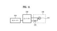
図11は、図6に示した送信部の構造の一例を示している。以下、図11を参照して、固定周波数を用いる送信部200によって補助共振を発生させる原理を説明する。 FIG. 11 shows an example of the structure of the transmission unit shown in FIG. Hereinafter, the principle of generating the auxiliary resonance by thetransmission unit 200 using a fixed frequency will be described with reference to FIG.

図11に示したように、送信部200(冷蔵庫本体)はオシレータ1510、インバータ1520、及び共振部1530で構成され、上記共振部1530はコイル1531及びコンデンサ1532で構成される。 As shown in FIG. 11, the transmission unit 200 (refrigerator body) is composed of anoscillator 1510, aninverter 1520, and aresonance unit 1530, and theresonance unit 1530 is composed of acoil 1531 and acapacitor 1532.

以前にも説明したように、送信部200(冷蔵庫本体)が単独で存在するとき(棚100が付着されなかった状態)、送信部200の共振器の共振周波数をf1、上記受信部300が装着されたときにさらに生成される共振周波数をf2とすると、f2>2f1となるように、該当の距離で受信部300の直列コンデンサ又は並列コンデンサを設定し(以前の図10などを参照)、図11、図12又は図13に示した送信部200の構成によって無線電力の伝送が可能である。 As described above, when the transmitter 200 (refrigerator body) is present alone (in a state where theshelf 100 is not attached), the resonance frequency of the resonator of thetransmitter 200 is set to f1, and thereceiver 300 is mounted. Assuming that the resonance frequency further generated is f2, a series capacitor or a parallel capacitor of thereceiver 300 is set at a corresponding distance so that f2> 2f1 (see the previous FIG. 10 and the like). Radio power can be transmitted by the configuration of thetransmission unit 200 shown in 11, 12 or 13.

さらに生成される2次共振周波数であるf2の周辺の固定周波数で送信部200を駆動すれば、送信部200が単独で存在するときに発生する送信部200の共振部の共振周波数(f1)、又は他の金属異物が近接するときに発生する送信部200の共振部の共振周波数は、共振周波数(f2)とは非常に違うため、送信部200の共振部には非常に少ない電流のみ流れることになる。 Further, if thetransmission unit 200 is driven at a fixed frequency around f2, which is the second-order resonance frequency generated, the resonance frequency (f1) of the resonance unit of thetransmission unit 200, which occurs when thetransmission unit 200 exists alone, Or, since the resonance frequency of the resonance part of thetransmission unit 200 generated when other metallic foreign matter is close to each other is very different from the resonance frequency (f2), only a very small current flows through the resonance part of thetransmission unit 200. become.

したがって、金属物質による誘導加熱は非常に低い水準であり、受信部300(棚100)が整列されたとき、補助共振の特性によってエネルギが充分に伝送される技術的効果がある。 Therefore, the induction heating by the metallic substance is at a very low level, and when the receiving units 300 (shelf 100) are aligned, there is a technical effect that energy is sufficiently transmitted due to the characteristics of the auxiliary resonance.

図11はこのような方法を用いる送信部200の構造の一例を示す。上記オシレータ1510は駆動しようとする周波数のパルス(PULSE)形態の出力を有し、上記インバータ1520はDCパワーを該当の周波数成分のACパワーに変換する。また、上記インバータ1520から出力されるACパワーを送信部200の共振器1530のコイル1531に流すことによって受信部300との磁気結合が発生してエネルギを伝送するようになる。 FIG. 11 shows an example of the structure of thetransmission unit 200 using such a method. Theoscillator 1510 has an output in the form of a pulse (PULSE) of the frequency to be driven, and theinverter 1520 converts DC power into AC power of the corresponding frequency component. Further, by passing the AC power output from theinverter 1520 through thecoil 1531 of theresonator 1530 of the transmittingunit 200, magnetic coupling with the receivingunit 300 is generated and energy is transmitted.

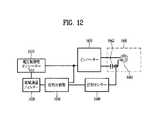
図12は、図6に示した送信部の構造の他の一例を示している。以下、図12を参照して、位相(phase)を感知する送信部200によって、補助共振を発生させる受信部300を感知する方法を説明する FIG. 12 shows another example of the structure of the transmission unit shown in FIG. Hereinafter, with reference to FIG. 12, a method of detecting the receivingunit 300 that generates the auxiliary resonance by the transmittingunit 200 that senses the phase will be described.

図12に示したように、送信部200(冷蔵庫本体)は、電圧制御型オシレータ(VCO)1610、低域通過フィルタ(Low Pass Filter)1620、位相感知器1630、位相センサ1640、インバータ1650及び共振部1660を含む。上記共振部1660はコイル1661及びコンデンサ1662で構成される。 As shown in FIG. 12, the transmission unit 200 (refrigerator body) includes a voltage controlled oscillator (VCO) 1610, a low pass filter (Low Pass Filter) 1620, aphase detector 1630, aphase sensor 1640, aninverter 1650, and resonance. Includespart 1660. Theresonance portion 1660 is composed of acoil 1661 and acapacitor 1662.

図12は、送信部200(冷蔵庫の本体)と受信部300(棚100)とが整列されるとき、送信部200の共振部1660での明らかな電流/電圧間の位相差の変化を観測して受信部300(棚100)を感知する方法である。図11と比較して説明すると、図11のオシレータ1510は電圧制御型オシレータ(VCO、Voltage Controller Oscillator)に変更され、送信部200の共振部1660の整流とインバータ1650の駆動周波数との位相差を感知するための位相センサ1640、位相比較器1630、及びフィードバックシステムが発振しないようにするLPF1620が付け加えられた。 FIG. 12 observes a clear change in phase difference between current / voltage at theresonant portion 1660 of thetransmitter 200 when the transmitter 200 (refrigerator body) and the receiver 300 (shelf 100) are aligned. This is a method of sensing the receiving unit 300 (shelf 100). Explaining in comparison with FIG. 11, theoscillator 1510 of FIG. 11 is changed to a voltage controlled oscillator (VCO, Voltage Controller Oscillator), and the phase difference between the rectification of theresonance portion 1660 of thetransmission unit 200 and the drive frequency of theinverter 1650 is changed. Aphase sensor 1640 for sensing, aphase comparator 1630, and anLPF 1620 to prevent the feedback system from oscillating have been added.

動作アルゴリズムは次の通りである。 The operation algorithm is as follows.

まず、図12に示した送信部200はf2(補助共振周波数又は2次共振周波数という)より高い周波数で駆動し始め、受信部300が整列されたときにのみ発生する送信部200の共振部の特定の電圧/電流位相差を有する動作点(operating point)をf2を含む特定の周波数範囲内で探索する。図4に示したように、2次共振はいずれか一つの特定周波数ではない所定の周波数帯域で発生するので、上記特定周波数範囲は少なくとも図4に示した2次共振が発生し得る周波数帯域の一部を含むかあるいは上記2次共振周波数帯域の全体を含むことができる。また、上記特定周波数範囲は上記2次共振周波数帯域より広く又は狭く設定されることもできる。 First, thetransmission unit 200 shown in FIG. 12 starts to drive at a frequency higher than f2 (referred to as an auxiliary resonance frequency or a secondary resonance frequency), and the resonance unit of thetransmission unit 200 that occurs only when thereception units 300 are aligned. An operating point having a specific voltage / current phase difference is searched for within a specific frequency range including f2. As shown in FIG. 4, since the secondary resonance occurs in a predetermined frequency band other than any one specific frequency, the specific frequency range is at least the frequency band in which the secondary resonance shown in FIG. 4 can occur. It may include a part or the whole of the second-order resonance frequency band. Further, the specific frequency range may be set wider or narrower than the secondary resonance frequency band.

該当の特定周波数範囲内で動作点の発見(探索)が不可能(cannot be found)な場合、異物(棚100ではない他の金属)が近接したかあるいは受信部300(棚100)が分離されたと判断し、送信部200に供給される電源をオフさせる。 If the operating point cannot be found within the specific frequency range, a foreign object (other metal other than the shelf 100) is close to the operating point, or the receiving unit 300 (shelf 100) is separated. It is determined that the power supply to thetransmission unit 200 is turned off.

一方、該当の特定周波数範囲内で動作点が発見(探索)された(found)場合には、受信部300(棚100)が整列された状態であると判断し、該当の位相差が維持される限り、持続的にエネルギ(電力)を伝送するように設計する。 On the other hand, when the operating point is found (found) within the specific frequency range, it is determined that the receiving units 300 (shelf 100) are aligned, and the corresponding phase difference is maintained. Design to transmit energy (power) continuously as long as possible.

図11に示した固定周波数駆動方式に比べ、図12に示したいわゆる位相感知法は次のような利点がある。 Compared with the fixed frequency drive method shown in FIG. 11, the so-called phase sensing method shown in FIG. 12 has the following advantages.

第一に、受信部300(棚100)の整列状態を感知して待機電力を減らす技術的効果がある。第二に、異物の整列状態を感知して誘導加熱の可能性を防止する技術的効果がある。第三に、送受信部の構成分子(部品)(constituent elements)に散乱(散布)(scattering)が発生しても一定した動作点を維持することができる技術的効果がある。 First, there is a technical effect of detecting the alignment state of the receiving unit 300 (shelf 100) and reducing the standby power. Secondly, there is a technical effect of detecting the alignment state of foreign substances and preventing the possibility of induction heating. Thirdly, there is a technical effect that a constant operating point can be maintained even if scattering occurs in the constituent molecules (components) of the transmission / reception unit.

図13は、図6に示した送信部構造のさらに他の一例を示している。以下、図13を参照して、入力電力を感知する送信部200によって補助共振を発生させる原理を説明する。 FIG. 13 shows still another example of the transmitter structure shown in FIG. Hereinafter, the principle of generating the auxiliary resonance by thetransmission unit 200 that senses the input power will be described with reference to FIG.

図13に示したように、送信部200(冷蔵庫本体)は、電圧制御型オシレータ(VCO)1710、増幅器(Amplifier)1720、低域通過フィルタ(Low Pass Filter)1730、入力電流感知器1740、インバータ1750及び共振部1760を含む。上記共振部1760はコイル1761及びコンデンサ1762で構成される。 As shown in FIG. 13, the transmitter 200 (refrigerator body) includes a voltage-controlled oscillator (VCO) 1710, an amplifier (Amplifier) 1720, a low-pass filter (Low Pass Filter) 1730, an inputcurrent detector 1740, and an inverter. Includes 1750 andresonance 1760. Theresonance portion 1760 is composed of acoil 1761 and acapacitor 1762.

補助共振(又は2次共振)周波数であるf2で動作するとき、受信部300(棚100)が整列されたときにのみ電力が大きく伝達され、負荷別及び距離別の効率差は大きくないので、受信部300の電力を制御したい場合、送信部200で電力を制御することが可能である。 When operating at f2, which is the auxiliary resonance (or secondary resonance) frequency, power is largely transmitted only when the receivers 300 (shelf 100) are aligned, and the efficiency difference between load and distance is not large. When it is desired to control the power of the receivingunit 300, the power can be controlled by the transmittingunit 200.

図13はこのような特徴を用いる送信部電力制御方法を示す。図11に示した固定周波数駆動方法に比べ、電力を測定するための入力電流感知器1740、入力電流には駆動周波数成分が混じっているのでこれを除去するための低域通過フィルタ(LPF)1730、及びフィルタリングされた入力電流値を特定値でフィードバックさせレファレンス電圧及びOPAMP1720が付け加えられた。 FIG. 13 shows a transmission unit power control method using such a feature. Compared to the fixed frequency drive method shown in FIG. 11, the inputcurrent sensor 1740 for measuring electric power and the low frequency pass filter (LPF) 1730 for removing the drive frequency component are mixed in the input current. , And the filtered input current value was fed back at a specific value, and the reference voltage and OPAMP1720 were added.

図13に示した電力制御方法の駆動アルゴリズムは次の通りである。 The driving algorithm of the power control method shown in FIG. 13 is as follows.

送信部200(冷蔵庫本体)は上記f2より高い周波数で駆動し始め、特定の入力電流を有する動作点をf2を含む特定の周波数範囲内で探索する。 The transmission unit 200 (refrigerator body) starts to drive at a frequency higher than f2, and searches for an operating point having a specific input current within a specific frequency range including f2.

該当の特定周波数範囲内で動作点の発見(探索)が不可能な場合、異物(棚100ではない他の金属)が近接したかあるいは受信部300(棚100)が分離されたと判断し、送信部200に供給される電源をオフさせる。 If it is not possible to find (search) the operating point within the specific frequency range, it is determined that a foreign object (other metal other than the shelf 100) is close to the device or the receiver 300 (shelf 100) is separated, and transmission is performed. The power supplied to theunit 200 is turned off.

一方、該当の特定周波数範囲内で動作点が発見(探索)された場合には、受信部300(棚100)が整列された状態であると判断し、該当の入力電圧が維持される限り、持続的にエネルギ(電力)を伝送するように設計する。 On the other hand, when an operating point is found (searched) within the specific frequency range, it is determined that the receiving units 300 (shelf 100) are aligned, and as long as the corresponding input voltage is maintained. Designed to transmit energy (electric power) continuously.

図11に示した固定周波数駆動方式に比べ、図13に示したいわゆる入力電力感知方法は次のような利点がある。 Compared with the fixed frequency drive method shown in FIG. 11, the so-called input power sensing method shown in FIG. 13 has the following advantages.

第一に、受信部300(棚100)の整列状態を感知して待機電力を減らす技術的効果がある。第二に、異物の整列状態を感知して誘導加熱の可能性を防止する技術的効果がある。第三に、送受信部の構成分子に散乱が発生しても一定の動作点を維持することができる技術的効果がある。第四に、送信部200(冷蔵庫本体)及び受信部300(冷蔵庫の棚100)のそれぞれのコイル間の結合が変更されても(例えば、送信部200のコイルと受信部300のコイルとの間の距離変更など)、一定の動作点を維持させることができる技術的効果がある。第五に、静電力駆動によって安定した負荷駆動が可能である。例えば、LED負荷の場合、別途の静電流駆動器が必要でない利点がある。 First, there is a technical effect of detecting the alignment state of the receiving unit 300 (shelf 100) and reducing the standby power. Secondly, there is a technical effect of detecting the alignment state of foreign substances and preventing the possibility of induction heating. Thirdly, there is a technical effect that a constant operating point can be maintained even if scattering occurs in the constituent molecules of the transmission / reception unit. Fourth, even if the coupling between the coils of the transmitting unit 200 (refrigerator body) and the receiving unit 300 (refrigerator shelf 100) is changed (for example, between the coil of the transmittingunit 200 and the coil of the receiving unit 300). There is a technical effect that a constant operating point can be maintained (such as changing the distance). Fifth, stable load drive is possible by electrostatic force drive. For example, in the case of an LED load, there is an advantage that a separate static current drive is not required.

前述したように、本出願の一例による無線電力伝送システムを用いて冷蔵庫を設計すれば、着脱可能なそれぞれの棚100に光源(すなわち、LED)を構築することが可能である。 As described above, if the refrigerator is designed using the wireless power transmission system according to the example of the present application, it is possible to construct a light source (that is, an LED) on eachdetachable shelf 100.

従来技術によると、冷蔵庫内の着脱可能な棚100に装着されるLEDの場合、接点方式のコネクタを用いるので、老化及び腐食の危険を持っている。しかし、本出願の一例はこのような問題点を解決することができる。 According to the prior art, in the case of the LED mounted on theremovable shelf 100 in the refrigerator, since the contact type connector is used, there is a risk of aging and corrosion. However, an example of this application can solve such a problem.

冷蔵庫の内側壁面に送信部200を装着し、棚100に受信部300を装着し、補助共振点を用いて無線で電力を伝送することにより、棚100に効果的に電力を無線で伝送するだけでなく、棚100を取り出し、アルミニウム素材の飲料水缶又は鉄系の鍋などを載せても、これらが誘導加熱されるかあるいは過度な共振によって送信部200が破損されないようにすることが可能である。前述したように、本出願の一例は補助共振点(2次共振点)を用いてこのようなおそれの事項を全て解決することができるので、非常に有用である。 By mounting thetransmitter 200 on the inner wall surface of the refrigerator, mounting thereceiver 300 on theshelf 100, and transmitting power wirelessly using the auxiliary resonance point, the power can be effectively transmitted wirelessly to theshelf 100. Instead, even if theshelf 100 is taken out and a drinking water can made of an aluminum material or an iron-based pot is placed on theshelf 100, it is possible to prevent thetransmitter 200 from being damaged by induction heating or excessive resonance. is there. As described above, one example of the present application is very useful because it is possible to solve all such problems by using the auxiliary resonance point (secondary resonance point).

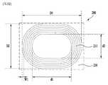
一方、冷蔵庫の本体に内蔵された送信部200のコイル及び冷蔵庫の棚100に内蔵された受信部300のコイルはいずれもPCBコイルで製作され、コイルにはMnZn系のフェライト(遮蔽部材)を重ねて当てることによって送受信コイル間の相互インダクタンスを増加させた。 On the other hand, the coil of the transmittingunit 200 built in the main body of the refrigerator and the coil of the receivingunit 300 built in theshelf 100 of the refrigerator are both manufactured of PCB coils, and MnZn-based ferrite (shielding member) is laminated on the coils. The mutual inductance between the transmitting and receiving coils was increased by hitting the coil.

上記遮蔽部材は送信部200及び受信部300のいずれにも適用可能であり、遮蔽部材の厚さは1.2〜10mm程度が適当である。また、上記遮蔽部材は堅い(rigid)プレート(plate)だけでなくフレキシブルなシート(sheet)でもなることができる。 The shielding member can be applied to both the transmittingunit 200 and the receivingunit 300, and the thickness of the shielding member is appropriately about 1.2 to 10 mm. Further, the shielding member can be not only a rigid plate but also a flexible sheet.

また、送信部200の共振部の具体的な仕様は、例えばコイルインダクタンスは約9.3μH、直列コンデンサは約100nF、そして送信部200単独で存在する場合の共振周波数は約150kHzである。 The specific specifications of the resonance portion of thetransmission unit 200 are, for example, a coil inductance of about 9.3 μH, a series capacitor of about 100 nF, and a resonance frequency of about 150 kHz when thetransmitter 200 alone exists.

一方、受信部300の共振部の具体的な仕様は、例えばコイルインダクタンスは約36μH、直列コンデンサは約4.7nF、並列コンデンサは約2.2nF、そして送信部200と受信部300との結合時に発生する補助共振周波数は約350kHzである。もちろん、送信/受信部の結合状態によって上記補助共振周波数は違うことができ、送信部200と受信部300とが約9mmの間隔で整列されたときの実験値である。 On the other hand, the specific specifications of the resonance part of thereceiver 300 are, for example, a coil inductance of about 36 μH, a series capacitor of about 4.7 nF, a parallel capacitor of about 2.2 nF, and when thetransmitter 200 and thereceiver 300 are coupled. The generated auxiliary resonance frequency is about 350 kHz. Of course, the auxiliary resonance frequency can be different depending on the coupling state of the transmission / reception unit, and is an experimental value when thetransmission unit 200 and thereception unit 300 are aligned at an interval of about 9 mm.

最後に、受信部300の負荷の具体的な仕様は、例えば負荷の種類としてはLED負荷を使い、等価負荷抵抗は約50Ωである。 Finally, the specific specifications of the load of the receivingunit 300 are, for example, an LED load is used as the type of load, and the equivalent load resistance is about 50Ω.

一方、本出願の他の一例として、それぞれの棚100が異なる(他の)(different)色(カラー)(color)又は明るさの光を発光するように設計することも可能である。これを具現するために、それぞれの棚100の側面に位置する冷蔵庫本体(送信部200)に供給される電力の量を異なるように(差別的に)(differentially)調節することができる。また、無線電力伝送モジュールに電圧(電源)(voltage)が印加されれば電力が伝送され、電圧が遮断されれば電力伝送が遮断される原理を用いて電源をオフしたりオンしたりする(オフさせてからオンさせる)デューティサイクル(duty cycle at which the power supply is turned on or off)を調節してディミング(dimming)を具現することができる。さらに、図4に示したように、補助共振周波数から駆動周波数が高くなるほど電力伝送が低くなる点に基づき、駆動周波数を用いてディミング(dimming)を具現することができる。すなわち、補助共振周波数から漸次的に駆動周波数を高めて光源の明るさを漸次的に減らすことができる。反対に、補助共振周波数まで漸次的に駆動周波数を減少させて光源の明るさを漸次的に増加させることができる。 On the other hand, as another example of the present application, it is also possible to design eachshelf 100 to emit light of a different (different) color (color) or brightness. In order to realize this, the amount of electric power supplied to the refrigerator main body (transmission unit 200) located on the side surface of eachshelf 100 can be adjusted differently (differentially). In addition, power is transmitted when a voltage is applied to the wireless power transmission module, and power is turned off and on using the principle that power transmission is cut off when the voltage is cut off (the power supply is turned off and on). Dimming can be achieved by adjusting the duty cycle at which the power supply is turned on or off. Further, as shown in FIG. 4, dimming can be realized by using the drive frequency based on the point that the power transmission decreases as the drive frequency increases from the auxiliary resonance frequency. That is, the drive frequency can be gradually increased from the auxiliary resonance frequency to gradually reduce the brightness of the light source. On the contrary, the driving frequency can be gradually decreased to the auxiliary resonance frequency to gradually increase the brightness of the light source.

上記棚100の照明のディミング(dimming)技術は、冷蔵庫ドアの開放時に照明を徐々に明るくして視認性を高める効果があり、冷蔵庫の周辺温度又は時間によって棚100の照明の明るさを調節することができる。上記ディミング技術は多様な色(例えば、R、G、B)を組み合わせてカラー照明も可能にする。 The dimming technology of the lighting of theshelf 100 has the effect of gradually brightening the lighting when the refrigerator door is opened to improve visibility, and adjusts the brightness of the lighting of theshelf 100 according to the ambient temperature or time of the refrigerator. be able to. The dimming technique also enables color illumination by combining various colors (eg, R, G, B).

先に詳細に説明したように、複数のコイルを用いた無線電力伝送システムにおいて、送信部は予め設定された電圧を受信するモジュール、流れる電流によって磁束(magnetic flux)を発生させる第1コイル及び第1コイルと直列に接続されて第1共振周波数を発生させる第1コンデンサを含むことができる。上記送信部から離隔した受信部は、電力を消費する負荷、第1コイルと磁束を鎖交して電流を誘導する第2コイル、並びに受信部が送信部と整列されたときに補助共振を発生させることができるように上記負荷の等価抵抗によって第2コイルと直列に接続された第2コンデンサ若しくは並列に接続された第3コンデンサを含むことができる。 As described in detail above, in a wireless power transmission system using a plurality of coils, the transmitter is a module that receives a preset voltage, a first coil that generates magnetic flux by a flowing current, and a first coil. It can include a first capacitor that is connected in series with one coil to generate a first resonance frequency. The receiving unit separated from the transmitting unit generates an auxiliary resonance when the load that consumes power, the second coil that induces a current by interlinking the first coil and the magnetic flux, and the receiving unit are aligned with the transmitting unit. A second capacitor connected in series with the second coil or a third capacitor connected in parallel with the equivalent resistance of the load can be included so that the load can be generated.

このような無線電力伝送システムは、送信部と受信部とが整列されたときに発生する補助共振点を用い、受信部が脱離されたときに送信部コイルで過度な共振エネルギ(電流)が発生する問題点及び伝送部と受信部とが脱離された後に金属異物が近接するときに上記金属異物を誘導加熱させる問題点を解決することができる。また、上記無線電力伝送システムは、受信部が脱離されたときに待機電力を最小にすることができる。その上、無線電力伝送システムは不必要な回路を最小にすることによって単純化し、高効率を達成することができる。 Such a wireless power transmission system uses an auxiliary resonance point generated when the transmitter and the receiver are aligned, and when the receiver is detached, an excessive resonance energy (current) is generated in the transmitter coil. It is possible to solve the problem that occurs and the problem that the metal foreign matter is induced and heated when the metallic foreign matter comes close to each other after the transmission unit and the receiving unit are separated from each other. Further, the wireless power transmission system can minimize the standby power when the receiving unit is detached. Moreover, wireless power transfer systems can be simplified and highly efficient by minimizing unnecessary circuits.

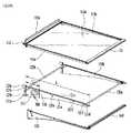
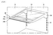
先に図2〜図13を参照して説明した回路的構成、つまり機能的構成を含むとともに、送信部200及び受信部300は冷蔵庫の棚100に多様な機械的構成、つまり構造的構成を有するように適用されることができる。このような機械的構成のうち、送信部200及び受信部300の配置が設計的観点で重要であり得るので、先に考慮する必要がある。より詳細には、送信部200及び受信部300の配置が決定されれば、棚100及び関連構造がこのような配置に基づいて容易に設計可能である。よって、図14は冷蔵庫の貯蔵室及び棚を概略的に示す斜視図であり、以下で送信部200及び受信部200の配置を図14に基づいて説明する。 In addition to including the circuit configuration, that is, the functional configuration described above with reference to FIGS. 2 to 13, the transmittingunit 200 and the receivingunit 300 have various mechanical configurations, that is, structural configurations on theshelf 100 of the refrigerator. Can be applied as Among such mechanical configurations, the arrangement of the transmittingunit 200 and the receivingunit 300 can be important from a design point of view, and therefore needs to be considered first. More specifically, once the arrangement of the transmittingunit 200 and the receivingunit 300 is determined, theshelf 100 and the related structure can be easily designed based on such an arrangement. Therefore, FIG. 14 is a perspective view schematically showing the storage room and the shelves of the refrigerator, and the arrangement of the transmittingunit 200 and the receivingunit 200 will be described below with reference to FIG.

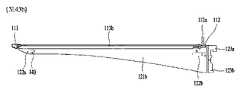
前述したように、棚100は貯蔵室2内の取付けのために側壁15又は後壁13によって支持されることができる。また、送信部200及び受信部300は、磁束、つまり電磁波を用いて無線で電力を伝送するためには互いに向き合っていなければならない。したがって、互いに向き合う棚100及び冷蔵庫(貯蔵室2)の部分、つまり棚100の側部100a、100b/側壁15a、15b又は棚100の後方部100c、100d/後壁13a、13bに送信部200及び受信部300が取り付けられることができる。実在に棚100は薄板の形状を有するので、その側部100a、100b又は後方部100c、100dは送信部200又は受信部300を直接設置するのに適切でないこともある。よって、図示のように、送信部200又は受信部300の取付けのためのフランジ100e、100fが棚の側部100a、100b及び後方部100c、100dにそれぞれ提供されることができる。 As mentioned above, theshelves 100 can be supported byside walls 15 orrear walls 13 for mounting within thestorage chamber 2. Further, the transmittingunit 200 and the receivingunit 300 must face each other in order to wirelessly transmit electric power using magnetic flux, that is, electromagnetic waves. Therefore, thetransmission unit 200 and the portions of theshelves 100 and the refrigerator (storage chamber 2) facing each other, that is, theside portions 100a, 100b /side walls 15a, 15b of theshelves 100 or the rear portions 100c, 100d /rear walls 13a, 13b of theshelves 100, and thetransmission unit 200 and The receivingunit 300 can be attached. Since theshelf 100 actually has the shape of a thin plate, itsside portions 100a, 100b or rear portions 100c, 100d may not be suitable for directly installing the transmittingunit 200 or the receivingunit 300. Therefore, as shown, flanges 100e and 100f for mounting the transmittingunit 200 or the receivingunit 300 can be provided on theside portions 100a and 100b and the rear portions 100c and 100d of the shelf, respectively.

送信部200は側壁15a、15bに配置されることもでき、後壁13a、13bに配置されることもできる。また、受信部300は上記送信部200と向き合うように棚100の側部100a、100b又は後方部100c、100dに配置されることができる。送信部200及び受信部300が側壁15a、15b及び棚100の側部100a、100bにそれぞれ配置される場合、このような送信部200及び受信部300は使用者によく見えないので、冷蔵庫の外観が向上することができる。したがって、送信部200及び受信部300を側壁15a、15b及び棚100の側部100a、100bにそれぞれ配置することを先に考慮することができる。図16〜図45で説明する棚100はこのように配置された送信部200及び受信部300を有する。より詳細には、受信部300は受信した電圧を棚の光源に供給するために棚100の側部100a、100bに取り付けられることができ、送信部200は外部電源と接続されるとともに受信部300と向き合うように側壁15a、15bに取り付けられることができる。一方(alternatively)、後壁13a、13bの後側には多様な機械装置が電源と接続されて配置されるので、送信部200が後壁13a、13bに配置されれば、外部電源に容易に接続されることができる。したがって、後述する図46及び図47の例のように、送信部200及び受信部300が後壁13a、13b及び棚100の後方部100c、100dにそれぞれ配置されることもできる。 Thetransmission unit 200 can be arranged on theside walls 15a and 15b, and can also be arranged on therear walls 13a and 13b. Further, the receivingunit 300 can be arranged on theside portions 100a, 100b or the rear portions 100c, 100d of theshelf 100 so as to face the transmittingunit 200. When the transmittingunit 200 and the receivingunit 300 are arranged on theside walls 15a and 15b and theside portions 100a and 100b of theshelf 100, respectively, such atransmitting unit 200 and the receivingunit 300 are not clearly visible to the user, so that the appearance of the refrigerator Can be improved. Therefore, it can be considered first that the transmittingunit 200 and the receivingunit 300 are arranged on theside walls 15a and 15b and theside portions 100a and 100b of theshelf 100, respectively. Theshelves 100 described with reference to FIGS. 16 to 45 have a transmittingunit 200 and a receivingunit 300 arranged in this way. More specifically, the receivingunit 300 can be attached to theside portions 100a and 100b of theshelf 100 in order to supply the received voltage to the light source of the shelf, and the transmittingunit 200 is connected to an external power source and the receivingunit 300. It can be attached to theside walls 15a and 15b so as to face each other. On the other hand (alternatively), various mechanical devices are arranged on the rear side of therear walls 13a and 13b in connection with the power supply. Therefore, if thetransmission unit 200 is arranged on therear walls 13a and 13b, it can be easily connected to the external power source. Can be connected. Therefore, as in the examples of FIGS. 46 and 47 described later, the transmittingunit 200 and the receivingunit 300 can be arranged on therear walls 13a and 13b and the rear portions 100c and 100d of theshelf 100, respectively.

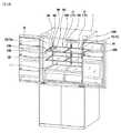
棚100は前述したように配置された送信部200及び受信部300と機能的及び構造的に最適に接続されるように設計することができる。このような棚100を関連図面に基づいて以下で詳細に説明する。図16a及び図16bは本出願による棚を左側及び右側からそれぞれ見た斜視図、図17及び図18は図16の棚の分解斜視図である。また、図19はカバー、受信部及び送信部を含む棚の部分斜視図、図20aは受信部及び光源部のアセンブリを示す平面図、図20bはカバーの内部構造を詳細に示す平面図である。 Theshelf 100 can be designed to be functionally and structurally optimally connected to thetransmitter 200 andreceiver 300 arranged as described above. Such ashelf 100 will be described in detail below with reference to the relevant drawings. 16a and 16b are perspective views of the shelves according to the present application as viewed from the left and right sides, respectively, and FIGS. 17 and 18 are exploded perspective views of the shelves of FIG. Further, FIG. 19 is a partial perspective view of the shelf including the cover, the receiving unit and the transmitting unit, FIG. 20a is a plan view showing the assembly of the receiving unit and the light source unit, and FIG. 20b is a plan view showing the internal structure of the cover in detail. ..

図1及び図14を参照して説明したように、貯蔵空間を効率的に使うために、複数の棚100が後壁13に支持されるとともに上記貯蔵室2の左右側にそれぞれ配置されることができる。図16aは冷蔵庫を正面から見たとき、貯蔵室2の左側に配置される棚100を示し、図16bは冷蔵庫を正面から見たとき、貯蔵室2の右側に配置された棚100を示す。前述したように、また図19、図21及び図23にも示したように、送信部200及び受信部300は無線電力送受信のために互いに向き合うように、側壁15及び上記側壁15と向き合う棚100の側部に配置されることができる。このような場合、図16aの棚100において、左側部100aが左側壁15aと向き合うので、受信部300は棚100の左側部100aに配置され、送信部200は左側壁15aに配置されることができる。また、図16bの棚100の場合、右側部100bが右側壁15bと向き合うので、受信部300は棚100の右側部100bに配置され、送信部200は右側壁15bに配置されることができる。また、図示の棚100は、左右側にそれぞれ配置されるために後壁13上に固定又は支持されるので、図示したように左右側ブラケット121a、121bを有することができる。これらのブラケット121a、121bは棚100の左右側部100a、100bをそれぞれなし、受信部300の取付けに十分な空間を提供することができる。したがって、図16aの棚100の場合、受信部300が左側ブラケット121aに取り付けられ、図16bの棚100の場合、受信部300が右側ブラケット121bに取り付けられることができる。このようなブラケット121a、121bのアセンブリは後でより詳細に説明する。一方、図1及び図16に示したものとは違い、冷蔵庫が左右側壁15a、15bにかけて連続して伸びる単一棚100を有する場合、送信部200及び受信部300は左側壁15a/棚左側部100a及び右側壁15b/棚右側部100bのいずれか一つに選択的に取り付けられることができる。 As described with reference to FIGS. 1 and 14, a plurality ofshelves 100 are supported by therear wall 13 and arranged on the left and right sides of thestorage chamber 2 in order to efficiently use the storage space. Can be done. FIG. 16a shows theshelves 100 arranged on the left side of thestorage chamber 2 when the refrigerator is viewed from the front, and FIG. 16b shows theshelves 100 arranged on the right side of thestorage chamber 2 when the refrigerator is viewed from the front. As described above, and as also shown in FIGS. 19, 21 and 23, the transmittingunit 200 and the receivingunit 300 face theside wall 15 and theside wall 15 so as to face each other for wireless power transmission / reception. Can be placed on the side of. In such a case, in theshelf 100 of FIG. 16a, since the left side portion 100a faces theleft side wall 15a, the receivingunit 300 may be arranged on the left side portion 100a of theshelf 100, and the transmittingunit 200 may be arranged on theleft side wall 15a. it can. Further, in the case of theshelf 100 of FIG. 16b, since theright side portion 100b faces theright side wall 15b, the receivingunit 300 can be arranged on theright side portion 100b of theshelf 100, and the transmittingunit 200 can be arranged on theright side wall 15b. Further, since the illustratedshelf 100 is fixed or supported on therear wall 13 because it is arranged on the left and right sides, respectively, it is possible to have the left andright side brackets 121a and 121b as shown. Thesebrackets 121a and 121b form the left andright side portions 100a and 100b of theshelf 100, respectively, and can provide a sufficient space for mounting the receivingportion 300. Therefore, in the case of theshelf 100 of FIG. 16a, the receivingunit 300 can be attached to theleft side bracket 121a, and in the case of theshelf 100 of FIG. 16b, the receivingunit 300 can be attached to theright side bracket 121b. The assembly ofsuch brackets 121a, 121b will be described in more detail later. On the other hand, unlike those shown in FIGS. 1 and 16, when the refrigerator has asingle shelf 100 extending continuously from the left andright side walls 15a and 15b, the transmittingunit 200 and the receivingunit 300 are on theleft side wall 15a / left side of the shelf. It can be selectively attached to any one of 100a and theright side wall 15b / theright side portion 100b of the shelf.

このような基本的な構成に続いて、前述した図面をさらに参照して棚100の詳細な構成を説明すると次の通りである。 Following such a basic configuration, a detailed configuration of theshelf 100 will be described with reference to the above-mentioned drawings as follows.

まず、棚100は棚部材110を含むことができる。棚部材110上には冷蔵庫内に貯蔵される食品が置かれることができる。棚部材110は、上記食品を実質的に支持するプレート(plate)110aを含むことができる。上記プレート110aは実質的に棚部材110の大部分を占め、これによって上記棚部材110の胴体を形成することができる。プレート110aは食品の安定的な支持のために十分な強度を有することができる。プレート110aはその上に置かれた食品だけではなく他の棚100のプレート110aに置かれた食品も容易に識別することができるように透明部材でなることができる。また、棚部材110はプレート110aの両側部にそれぞれ配置されるレール(rail)113a、113bを含むことができる。このようなレール113a、113bはプレート110aの両側を支持するように構成されることができる。より詳細には、図24に明らかに示すように、レール113a、113bはその上部に形成されて長手方向に伸びるリセス(recess)113cを含むことができる。プレート110aの側部はこのようなリセス113c内に安定的に支持されることができる。また、棚部材100はプレート110aの前端部及び後端部にそれぞれ配置される前方カバー111及び後方カバー112を含むことができる。前方及び後方カバー111、112は露出されるプレート110aの前後端部を保護するとともに棚100の外観を向上させることができるデザインを有することができる。より詳細には、後方カバー112はその上部に取り付けられるバリア(barrier)112aを有することができる。バリア112aは後方カバー112から所定高さまで突出し、これによって棚部材110上に置かれる食品が棚の後方に落下することを防止することができる。このような棚部材110の組立ての際、まずプレート110aがレール113a、113bのリセス113c上に装着され、固定手段、例えば接着剤113fによって上記リセス113c上に固定されることができる。また、このようなプレート110a−レール113a、113bの予備アセンブリ(preliminary assembly)の前方端及び後方端に上記カバー111、112がそれぞれ結合され、プレート110aだけでなくレール113a、113bの末端もカバー111、112によって保持される(held)ことができる。よって、このような過程によって、プレート110a、レール113a、113b及びカバー111、112は一つのアセンブリ、つまり棚部材110として形成されることができる。 First, theshelf 100 can include ashelf member 110. Food stored in the refrigerator can be placed on theshelf member 110. Theshelf member 110 may include aplate 110a that substantially supports the food. Theplate 110a substantially occupies most of theshelf member 110, whereby the body of theshelf member 110 can be formed. Theplate 110a can have sufficient strength for stable support of food. Theplate 110a can be made of a transparent member so that not only the food placed on it but also the food placed on theplate 110a of theother shelf 100 can be easily identified. Further, theshelf member 110 can includerails 113a and 113b arranged on both sides of theplate 110a, respectively.Such rails 113a and 113b can be configured to support both sides of theplate 110a. More specifically, as clearly shown in FIG. 24, therails 113a, 113b can include a recess 113c formed above it and extending in the longitudinal direction. The side portion of theplate 110a can be stably supported in such a recess 113c. Further, theshelf member 100 can include afront cover 111 and arear cover 112 arranged at the front end portion and the rear end portion of theplate 110a, respectively. The front andrear covers 111, 112 can have a design that can protect the front and rear ends of the exposedplate 110a and improve the appearance of theshelf 100. More specifically, therear cover 112 can have abarrier 112a attached to its top. Thebarrier 112a projects from therear cover 112 to a predetermined height, whereby food placed on theshelf member 110 can be prevented from falling behind the shelf. When assembling such ashelf member 110, theplate 110a is first mounted on the recess 113c of therails 113a and 113b, and can be fixed on the recess 113c by a fixing means, for example, an adhesive 113f. Further, thecovers 111 and 112 are connected to the front end and the rear end of the preliminary assembly of theplates 110a-rails 113a and 113b, respectively, and not only theplate 110a but also the ends of therails 113a and 113b are covered 111. , 112 can be held. Therefore, by such a process, theplates 110a, therails 113a, 113b and thecovers 111, 112 can be formed as one assembly, that is, theshelf member 110.

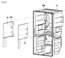
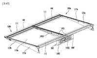
また、棚100は後壁13に対して上記棚部材110及びその上に置かれた食品を支持するように構成されるブラケット120を含むことができる。ブラケット120は棚部材110の下側に配置され、棚部材110の底部を支持することができる。ブラケット120は棚部材110の安定的な支持のために棚部材110の両側部にそれぞれ配置される左側及び右側ブラケット121a、121bでなることができる。より詳細には、このような左右側ブラケット121a、121bは棚部材110の左右側の下側に配置され、棚部材110の底部の左右側部をそれぞれ支持することができる。左右側ブラケット121a、121bは棚部材110の安定的な支持のために棚部材110の左右側部に沿って長く伸びることができる。また、ブラケット120は左右側ブラケット121a、121bを支持するように構成されるバー(bar)122a、122bを含むことができる。バー122a、122bは左右側ブラケット121a、121bの間に配置され、左右側ブラケット121a、121bに垂直に配向されることができる。また、バー122a、122bは左右側ブラケット121a、121bの前方及び後方にそれぞれ配置されることができる。バー122a、122bはブラケット121a、121bにボルトなどの固定部材で結合されることができ、あるいはブラケット121a、121bに直接熔接されることもできる。上記バー122a、122bは外力によるブラケット121a、121bのねじれや変形を防止することができ、よって棚100の強度を増加させることができる。このようなバー122a、122bは、適切な強度を有する限り、円形、楕円形、四角形などの多様な断面形を有することができる。例えば、図16cに示したように、前方バー122aは円形の断面を有する円柱部材でなるが、後方バー122bは四角形の断面を有するプレート部材でなることができる。 Further, theshelf 100 can include abracket 120 configured to support theshelf member 110 and food placed on theshelf member 110 with respect to therear wall 13. Thebracket 120 is arranged below theshelf member 110 and can support the bottom of theshelf member 110. Thebracket 120 may consist of left andright brackets 121a, 121b arranged on both sides of theshelf member 110 for stable support of theshelf member 110, respectively. More specifically, such left andright side brackets 121a and 121b are arranged on the lower left and right sides of theshelf member 110, and can support the left and right side portions of the bottom portion of theshelf member 110, respectively. The left andright brackets 121a and 121b can extend long along the left and right sides of theshelf member 110 for stable support of theshelf member 110. Further, thebracket 120 can includebars 122a and 122b configured to support the left andright brackets 121a and 121b. Thebars 122a and 122b are arranged between the left andright brackets 121a and 121b, and can be oriented perpendicularly to the left andright brackets 121a and 121b. Further, thebars 122a and 122b can be arranged in front of and behind the left andright side brackets 121a and 121b, respectively. Thebars 122a and 122b can be connected to thebrackets 121a and 121b with fixing members such as bolts, or can be directly welded to thebrackets 121a and 121b. Thebars 122a and 122b can prevent thebrackets 121a and 121b from being twisted or deformed by an external force, and thus can increase the strength of theshelf 100.Such bars 122a, 122b can have various cross-sectional shapes such as circular, elliptical, and quadrangular as long as they have appropriate strength. For example, as shown in FIG. 16c, thefront bar 122a may be a cylindrical member having a circular cross section, while therear bar 122b may be a plate member having a quadrangular cross section.

ブラケット120は棚部材110を支持するために後壁13に固定されるか支持されるように構成されることができる。このような固定及び支持のために、後壁13は上記ブラケット120の後端がかかって支持されることができる装着孔18を含むことができる。一方、食品の高さ及び大きさは互いに違うので、このような食品を効率的に貯蔵するために、棚100は垂直方向、つまり上方又は下方に移動可能に構成されることができる。よって、図1、図21及び図23に示したように、複数の装着孔18が垂直に一列に配置されることができる。また、このような複数の装着孔18の列(column)は左右側ブラケット121a、121bにそれぞれ提供されることができる。ブラケット121a、121bがいずれか一つの装着孔18から分離されて他の高さを有する他の装着孔18に結合されれば、棚100の高さが変化することができる。 Thebracket 120 can be configured to be fixed or supported to therear wall 13 to support theshelf member 110. For such fixation and support, therear wall 13 can include a mountinghole 18 that can be supported by the rear end of thebracket 120. On the other hand, since the heights and sizes of the foods are different from each other, theshelves 100 can be configured to be movable in the vertical direction, that is, upwards or downwards, in order to efficiently store such foods. Therefore, as shown in FIGS. 1, 21 and 23, a plurality of mountingholes 18 can be arranged vertically in a row. Further, such a row of a plurality of mountingholes 18 can be provided to the left andright side brackets 121a and 121b, respectively. If thebrackets 121a and 121b are separated from any one mountinghole 18 and coupled to another mountinghole 18 having another height, the height of theshelf 100 can be changed.

より詳細には、図16〜図19及び図22に詳細に示したように、ブラケット120は後壁13、つまり装着孔18に結合される第1係止片123a及び第2係止片123bを含むことができる。第1及び第2係止片123a、123bはブラケット120の後端部に提供され、上記後端部の上部及び下部にそれぞれ配置されることができる。上記第1係止片123aと上記第2係止片123bとは互いに異なる装着孔18に結合されることにより、上記ブラケット120を上記後壁に固定することができる。上記第1係止片123aは全体的に(generally)‘L’字形、つまりアングル形に形成され、上記ブラケット120の後端の上側に提供されることができる。上記第1係止片123aは上記装着孔18に挿入されれば、上記装着孔18の上側にかかり、上記ブラケット120の前端部が下方に垂れることを防止することができる。上記第2係止片123bは上記第1係止片123bの下部に提供され、上記装着孔18に挿入されることができる。上記第2係止片123bが上記装着孔18に挿入されれば、上記ブラケット120が上記第1係止片123aを中心に後壁13に向かって回転(pivot)することを防止し、よって上記ブラケット120の前端が下方に垂れることを防止することができる。上記第2係止片123bは機能的な違いによって上記第1係止片123aとは違う形状を有することが可能である。例えば、上記第2係止片123bは、図示のように、上記ブラケット120の後方から後方に向かって突出したピン(pin)形状を有することができる。 More specifically, as shown in detail in FIGS. 16-19 and 22, thebracket 120 has arear wall 13, i.e., afirst locking piece 123a and asecond locking piece 123b coupled to the mountinghole 18. Can include. The first andsecond locking pieces 123a and 123b are provided at the rear end portion of thebracket 120 and can be arranged at the upper portion and the lower portion of the rear end portion, respectively. Thebracket 120 can be fixed to the rear wall by connecting thefirst locking piece 123a and thesecond locking piece 123b to different mounting holes 18. Thefirst locking piece 123a is generally formed in an'L'shape, that is, an angle shape, and can be provided above the rear end of thebracket 120. When thefirst locking piece 123a is inserted into the mountinghole 18, it can be applied to the upper side of the mountinghole 18 to prevent the front end portion of thebracket 120 from hanging downward. Thesecond locking piece 123b is provided in the lower part of thefirst locking piece 123b and can be inserted into the mountinghole 18. When thesecond locking piece 123b is inserted into the mountinghole 18, thebracket 120 is prevented from rotating (pivot) toward therear wall 13 about thefirst locking piece 123a, and thus the above. It is possible to prevent the front end of thebracket 120 from hanging downward. Thesecond locking piece 123b can have a shape different from that of thefirst locking piece 123a due to a functional difference. For example, thesecond locking piece 123b can have a pin shape that protrudes from the rear to the rear of thebracket 120, as shown in the figure.

上記装着孔18において、上記第1係止片123aに挿入されるための装着孔と上記第2係止片123bに挿入されるための装着孔とが隣り合って配置されて対を形成することができる。例えば、上記第1係止片123aが挿入されるための装着孔の大きさは上記第2係止片123bが挿入されるための装着孔の大きさより大きくなることができる。このような場合、上記第1係止片123aに挿入されるための装着孔と上記第2係止片123bに挿入されるための装着孔とが対をなすように順次配置されることが可能である。また、このような装着孔の対は、前述したように、後壁13に垂直に一列に配置されることができる。 In the mountinghole 18, the mounting hole for being inserted into thefirst locking piece 123a and the mounting hole for being inserted into thesecond locking piece 123b are arranged next to each other to form a pair. Can be done. For example, the size of the mounting hole for inserting thefirst locking piece 123a can be larger than the size of the mounting hole for inserting thesecond locking piece 123b. In such a case, the mounting holes for being inserted into thefirst locking piece 123a and the mounting holes for being inserted into thesecond locking piece 123b can be sequentially arranged so as to form a pair. Is. Further, as described above, such a pair of mounting holes can be arranged in a row perpendicular to therear wall 13.

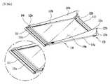
一方、使用者は棚100の後方に置かれた食品を取り出しにくいことがあり得る。よって、食品を容易に(易しく)(easy)取り出すことができるように、棚100は水平方向、つまり前方及び後方に移動可能に構成されることができる。実際的に、棚100の全体をこのように移動させることは構造的に難しくなることができるので、棚100の棚部材110が前方及び後方に移動可能に構成されることができる。このような前後方への移動のために、棚部材110のレール113a、113bはブラケット120にスライド可能に支持されるか結合されるように構成されることができる。図24は図16aのA−A線に沿って得られた断面図、図37は棚部材のレールを示す斜視図及び部分拡大図である。より詳細には、図24はプレート110a及び右側ブラケット121bと一緒に右側レール113bを示し、図37は関連の他の部材なしに右側レール113bのみを示す。これらの図面を参照し、前後方移動のためのメカニズム及びレールの詳細な構成を以下で説明する。 On the other hand, it may be difficult for the user to take out the food placed behind theshelf 100. Thus, theshelves 100 can be configured to be movable in the horizontal direction, i.e. forward and backward, so that food can be easily removed. Practically, it can be structurally difficult to move theentire shelf 100 in this way, so that theshelf member 110 of theshelf 100 can be configured to be movable forward and backward. For such anterior-posterior movement, therails 113a, 113b of theshelf member 110 can be configured to be slidably supported or coupled to thebracket 120. FIG. 24 is a cross-sectional view obtained along the line AA of FIG. 16a, and FIG. 37 is a perspective view and a partially enlarged view showing the rail of the shelf member. More specifically, FIG. 24 shows theright rail 113b with theplate 110a and theright bracket 121b, and FIG. 37 shows only theright rail 113b without any other related members. With reference to these drawings, the mechanism for forward / backward movement and the detailed configuration of the rail will be described below.

図24に示したように、ブラケット120、つまり右側ブラケット121bは右側レール113bをスライド可能に支持するように構成されたフランジ121cを含むことができる。フランジ121cはレール113bの底面を支持するように内方に伸びることができる。レール113bは、下方に伸び、フランジ121cの外側面上で支持される第1フランジ113dを含むことができる。また、レール113bは同様に下方に伸び、フランジ121cの内側面で支持される第2フランジ113eを含むことができる。第2フランジ113eはまた水平に外方に伸びる延長部を含むことができ、より安定的な支持のためにフランジ121cを取り囲むことができる。よって、レール113bはこのような第1及び第2フランジ113d、113eによって案内されながらフランジ121cに沿って移動することができる。このような第1及び第2フランジ113d、113e及びフランジ121cは左右レール113a、113b及びブラケット121a、121bに同様に適用されることができる。よって、図16dに示したように、左右レール113a、113bによって棚部材110が前方及び後方に移動することができる。棚部材110が前方に移動すれば、食品は使用者に近接することができ、よって使用者は便利に食品を取り出すことができる。一方、フランジ121cの上面がレール113bの底面と全体で接触すれば、面接触による相対的に大きな摩擦抵抗が発生し得る。よって、図24に示したように、レール113bはその底面に形成される突出部113hを含むことができる。突出部113hは第1及び第2フランジ113d、113eの間に配置されるように概して幅方向においてレール113bの底部の中央部に配置され、下方にフランジ121cに向かって伸びることができる。突出部113hはフランジ121cと相対的に小さい接触面を有するので、レール113bは大きな抵抗なしにフランジ121cに沿って移動することができる。よって、図16dに示したように、棚部材110はより円滑に前方及び後方に左右レール113a、113b及びブラケット121a、121bによって支持されながら移動することができる。 As shown in FIG. 24, thebracket 120, i.e. theright bracket 121b, may include aflange 121c configured to slidably support theright rail 113b. Theflange 121c can extend inward to support the bottom surface of therail 113b. Therail 113b may include a first flange 113d that extends downward and is supported on the outer surface of theflange 121c. Further, therail 113b can also include asecond flange 113e that extends downward and is supported by the inner surface of theflange 121c. Thesecond flange 113e can also include an extension that extends horizontally outwards and can surround theflange 121c for more stable support. Therefore, therail 113b can move along theflange 121c while being guided by the first andsecond flanges 113d and 113e. Such first andsecond flanges 113d, 113e andflange 121c can be similarly applied to the left andright rails 113a, 113b andbrackets 121a, 121b. Therefore, as shown in FIG. 16d, theshelf member 110 can be moved forward and backward by the left andright rails 113a and 113b. If theshelf member 110 moves forward, the food can be brought closer to the user, so that the user can conveniently take out the food. On the other hand, if the upper surface of theflange 121c comes into contact with the bottom surface of therail 113b as a whole, relatively large frictional resistance may be generated due to the surface contact. Therefore, as shown in FIG. 24, therail 113b can include aprotrusion 113h formed on the bottom surface thereof. Theprotrusion 113h is generally arranged in the central portion of the bottom of therail 113b in the width direction so as to be arranged between the first andsecond flanges 113d and 113e, and can extend downward toward theflange 121c. Since theprotrusion 113h has a relatively small contact surface with theflange 121c, therail 113b can move along theflange 121c without large resistance. Therefore, as shown in FIG. 16d, theshelf member 110 can move more smoothly forward and backward while being supported by the left andright rails 113a and 113b and thebrackets 121a and 121b.

冷蔵庫は前述したような移動可能な棚部材110を有する棚100だけでなく、上記棚部材110が動かないようにブラケット121a、121bに固定された棚100も含むことができる。例えば、使用者は貯蔵室2の上部に配置された棚100の後方に置かれた食品を取り出すことは難しいが、貯蔵室2の下部に配置された棚100の後方に置かれた食品を比較的容易に取り出すことができる。したがって、貯蔵室2の上部の棚100には移動可能な棚部材110が適用されることができ、貯蔵室2の下部の棚100には固定されて移動できない棚部材110が適用されることができる。すなわち、棚100の相対的位置及び他の要件を考慮して上記移動可能な棚部材110を選択的に適用することができる。 The refrigerator can include not only theshelf 100 having themovable shelf member 110 as described above, but also theshelf 100 fixed to thebrackets 121a and 121b so that theshelf member 110 does not move. For example, it is difficult for the user to take out the food placed behind theshelf 100 placed at the top of thestorage room 2, but compare the food placed behind theshelf 100 placed at the bottom of thestorage room 2. It can be easily taken out. Therefore, themovable shelf member 110 can be applied to theupper shelf 100 of thestorage chamber 2, and the fixed andimmovable shelf member 110 can be applied to thelower shelf 100 of thestorage chamber 2. it can. That is, themovable shelf member 110 can be selectively applied in consideration of the relative position of theshelf 100 and other requirements.

前述したように、リセス113c内に装着されたプレート110aは接着剤113fによってリセス113cの底面上に固定されることができる。このような固定をより効率的に行うために、多様な更なる構成がレール113a、113bに付け加えられることができる。図24及び図37はそのような構成をよく示す。まず、プレート110aがリセス113cの底部に固定されるとき、プレート110aが加圧されることができる。このような加圧によって接着剤113fがリセス113cの外部に流出することができ、棚100の外観を阻害することができる。このような理由で、レール113a、113bの上部、正確にはリセス113cの底面には、図24及び図37に示したように、溝113gが形成されることができる。上記溝113gはリセス113c上で流動する接着剤113fを収容し、よって接着剤113fがリセス113cの外部に流出することを防止することができる。接着剤113fの流出をより効果的に防止するために、一対の溝113gがリセス113cの底面上に形成されることができる。これらの一対の溝113gは互いに所定間隔で離隔し、レール113a、113bの長手方向に伸びることができる。よって、これらの溝113gの間に実質的な接着面113kが形成されることができる。また、リセス113cの底面上にはスペーサ(spacer)113iが形成されることができる。スペーサ113iはリセス113cの底面から上方に所定長さで伸びることができる。プレート110aは実質的にこのようなスペーサ113i上に置かれ、上記スペーサ113iによってプレート110aとリセス113cとの間には接着剤113fが充填可能な空間が形成されることができる。このような理由で、スペーサ113iは一対の溝113gの間に、より詳細には接着面113k上に配置されることができる。棚部材110の組立ての際、スペーサ113iの上部には接着部材、例えば両面テープが付けられることができ、プレート110aが上記スペーサ113i上に予備的に付着されることができる。その後、プレート110aは接着剤113fによってレール113bに最終的に固定されることができる。このような固定作業中、接着剤113fは上記溝113gによって外部に流出せずにプレート110aの固定に全部使われることができる。よって、前述した構成によって、棚100の外観を損なわなく、プレート110aはレール113a、113bによって堅固に固定されることができる。 As described above, theplate 110a mounted in the recess 113c can be fixed on the bottom surface of the recess 113c by the adhesive 113f. Various additional configurations can be added to therails 113a, 113b to make such fixation more efficient. 24 and 37 show such a configuration well. First, when theplate 110a is fixed to the bottom of the recess 113c, theplate 110a can be pressurized. By such pressurization, the adhesive 113f can flow out to the outside of the recess 113c, and the appearance of theshelf 100 can be impaired. For this reason,grooves 113g can be formed on the upper portions of therails 113a and 113b, more precisely on the bottom surface of the recess 113c, as shown in FIGS. 24 and 37. Thegroove 113g accommodates the adhesive 113f flowing on the recess 113c, and thus can prevent the adhesive 113f from flowing out of the recess 113c. A pair ofgrooves 113g can be formed on the bottom surface of the recess 113c to more effectively prevent the adhesive 113f from flowing out. These pair ofgrooves 113g are separated from each other at predetermined intervals and can extend in the longitudinal direction of therails 113a and 113b. Therefore, a substantialadhesive surface 113k can be formed between thesegrooves 113g. Further, a spacer 113i can be formed on the bottom surface of the recess 113c. The spacer 113i can extend upward from the bottom surface of the recess 113c by a predetermined length. Theplate 110a is substantially placed on such a spacer 113i, and the spacer 113i can form a space in which the adhesive 113f can be filled between theplate 110a and the recess 113c. For this reason, the spacer 113i can be arranged between the pair ofgrooves 113g, more specifically on theadhesive surface 113k. When assembling theshelf member 110, an adhesive member, for example, double-sided tape can be attached to the upper portion of the spacer 113i, and theplate 110a can be preliminarily attached onto the spacer 113i. Theplate 110a can then be finally fixed to therail 113b by the adhesive 113f. During such fixing work, the adhesive 113f can be completely used for fixing theplate 110a without flowing out due to thegroove 113g. Therefore, according to the above-described configuration, theplate 110a can be firmly fixed by therails 113a and 113b without impairing the appearance of theshelf 100.

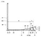
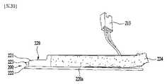
また、棚100は、受信部300から電源を受けて光を照射するように構成される光源部140を含むことができる。図25は棚の光源部の上部(top)を示す平面図、図26aは図25のB−B線に沿って得られた断面図、図26bは図16aのC−C線に沿って得られた断面図である。図27は前方に光を照射するように構成された棚の光源部を示す斜視図、図28は下方に光を照射するように構成された棚の光源部を示す斜視図である。また、図29は図27の光源部の底部(bottom)を示す平面図、図30a及び図30bはブラケットに結合された光源部を示す部分斜視図である。また、図36a〜図36eは光源部の右側及び左側キャップを示す斜視図及び上記キャップを示す平面図、正面図及び右側面図である。図38は冷蔵庫の内部を照明する壁体(wall)の光源を示す冷蔵庫の正面図、図39は冷蔵庫の内部を照明する壁体光源及び棚の光源部を示す冷蔵庫の断面図である。これらの図面に基づいて光源部140を詳細に説明すると次の通りである。また、図16〜図20は棚100の全体構造を詳細に示すので、以下の説明で一緒に参照する。 Further, theshelf 100 can include alight source unit 140 configured to receive power from the receivingunit 300 and irradiate light. 25 is a plan view showing the top of the light source portion of the shelf, FIG. 26a is a sectional view obtained along the line BB of FIG. 25, and FIG. 26b is obtained along the line CC of FIG. 16a. It is a cross-sectional view. FIG. 27 is a perspective view showing a light source portion of a shelf configured to irradiate light forward, and FIG. 28 is a perspective view showing a light source portion of a shelf configured to irradiate light downward. 29 is a plan view showing the bottom of the light source portion of FIG. 27, and FIGS. 30a and 30b are partial perspective views showing the light source portion coupled to the bracket. 36a to 36e are a perspective view showing the right and left caps of the light source unit, and a plan view, a front view, and a right side view showing the caps. FIG. 38 is a front view of the refrigerator showing a wall light source that illuminates the inside of the refrigerator, and FIG. 39 is a cross-sectional view of the refrigerator showing the wall light source that illuminates the inside of the refrigerator and the light source portion of the shelf. Thelight source unit 140 will be described in detail based on these drawings as follows. Further, since FIGS. 16 to 20 show the overall structure of theshelf 100 in detail, they will be referred to together in the following description.

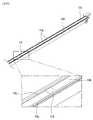
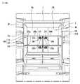
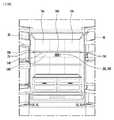
冷蔵庫の内部空間、つまり貯蔵室2は暗いから、使用者が貯蔵された食品を容易に捜すことができない。よって、図38及び図39に示したように、冷蔵庫の内部、つまり貯蔵室2を照明するために光源60A、60Bが提供されることができる。上記貯蔵室2の均一な照明のために、光源60A、60Bは、例えば上側壁12に取り付けられることができ、上側壁12の前方部及び後方部にそれぞれ配置されることができる。しかし、光源60A、60Bから放出された光は棚100及びその上に置かれた物品によって遮られて貯蔵室2の全領域に到逹することができない。よって、光源60A、60Bに加え、棚100に光源部140が取り付けられれば、このような光源部140は棚100の間の空間を直接照明することができる。このような理由で、棚100に取り付けられた光源部140によって使用者は棚100に置かれた物品をより易しく(clearly)確認することができ、貯蔵室2を均一に照明することができる。また、一般に、貯蔵室2の後方部が前方部に比べてより暗いから、前方光源60Aも、図39に示したように、貯蔵室2の後方部の照明のために、上記後方部に向かって配向されることができる。よって、貯蔵室2の前方部が相対的に貯蔵室2の後方部に比べて照明が不足であることがあり得る。このような理由で、貯蔵室2の前方部を照明することができるように、光源部140は棚100の前方部に配置されることができる。また、光源部140は均一な照明のために棚100の前方部に沿って連続して伸びることができる。実際的に光源部140はブラケット121a、121bの間に配置され、その左右側両端がブラケット121a、121bに結合されることができる。このような光源部140は貯蔵室2の前方部の照明を補うことができる。また、図39に示したように、光源部140から放出された光は直下にある食品又は他の棚によって反射されることができ、これによって貯蔵室2をより均一に照明することができる。また、図39に示したように、冷蔵庫は棚100の中央部に取り付けられる追加照明部140−1及び/又は棚100の後方部に取り付けられる追加照明部140−2を有することができる。このような追加照明部140−1、140−2は前方の照明部140と一緒に貯蔵室2をより均一に照明することができる。 Since the internal space of the refrigerator, that is, thestorage room 2 is dark, the user cannot easily search for the stored food. Therefore, as shown in FIGS. 38 and 39, thelight sources 60A and 60B can be provided to illuminate the inside of the refrigerator, that is, thestorage chamber 2. For uniform illumination of thestorage chamber 2, thelight sources 60A and 60B can be attached to, for example, theupper side wall 12, and can be arranged at the front portion and the rear portion of theupper side wall 12, respectively. However, the light emitted from thelight sources 60A and 60B cannot reach the entire area of thestorage chamber 2 because it is blocked by theshelf 100 and the articles placed on theshelf 100. Therefore, if thelight source unit 140 is attached to theshelf 100 in addition to thelight sources 60A and 60B, such alight source unit 140 can directly illuminate the space between theshelves 100. For this reason, thelight source unit 140 attached to theshelf 100 allows the user to more clearly check the articles placed on theshelf 100 and uniformly illuminate thestorage chamber 2. Further, since the rear portion of thestorage chamber 2 is generally darker than the front portion, the frontlight source 60A also faces the rear portion for illumination of the rear portion of thestorage chamber 2, as shown in FIG. 39. Can be oriented. Therefore, it is possible that the front portion of thestorage chamber 2 is relatively insufficient in lighting as compared with the rear portion of thestorage chamber 2. For this reason, thelight source unit 140 can be arranged in the front portion of theshelf 100 so that the front portion of thestorage chamber 2 can be illuminated. Also, thelight source unit 140 can extend continuously along the front portion of theshelf 100 for uniform illumination. Practically, thelight source unit 140 is arranged between thebrackets 121a and 121b, and both left and right ends thereof can be coupled to thebrackets 121a and 121b. Such alight source unit 140 can supplement the illumination of the front portion of thestorage chamber 2. Further, as shown in FIG. 39, the light emitted from thelight source unit 140 can be reflected by the food or other shelves directly underneath, whereby thestorage chamber 2 can be illuminated more uniformly. Further, as shown in FIG. 39, the refrigerator can have an additional illumination unit 140-1 attached to the central portion of theshelf 100 and / or an additional illumination unit 140-2 attached to the rear portion of theshelf 100. Such additional lighting units 140-1 and 140-2 can illuminate thestorage chamber 2 more uniformly together with thefront lighting unit 140.

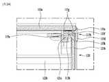
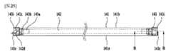
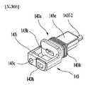
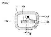
より詳細には、図17及び図25によく示したように、光源部140はハウジング141を含む。ハウジング141は中空管形状の部材でなることができる。また、光源部140は光を発光するように構成される光源モジュール142を含むことができる。モジュール142は、図29によく示したように、基板142aと基板に付着された発光素子142bとでなることができる。発光素子142bは、例えばLED(Light Emitting Diode)でなることができる。前述したように、均一な照明のために、光源部140は棚100の前方部に沿って(along)長く伸びるので、モジュール142の基板142aも同様に長く伸びたストリップ部材で形成され、発光素子142bも基板142aに沿って所定間隔で一列に配置されることができる。また、受信部300から電源を受けるために、モジュール142は基板142aに接続される配線142c、142dを含むことができ、これらの配線142c、142dは光源部140の外部に伸びて受信部300に接続されることができる。このようなモジュール142は、外部の環境から保護されるために、ハウジング141内に収容される。また、ハウジング141は、モジュール142で生成された光を所望の方向に照射するために、特定の部分を除いた残りの部分は不透明になる。すなわち、上記ハウジング141は、光を通過させないように構成される遮光部、及び光を通過させるように構成される透明部、つまりウィンドウ141c(図29参照)を含むことができる。 More specifically, as well shown in FIGS. 17 and 25, thelight source unit 140 includes ahousing 141. Thehousing 141 can be made of a hollow tube shaped member. Further, thelight source unit 140 can include alight source module 142 configured to emit light. As shown well in FIG. 29, themodule 142 can consist of thesubstrate 142a and thelight emitting element 142b attached to the substrate. Thelight emitting element 142b can be made of, for example, an LED (Light Emitting Diode). As described above, for uniform illumination, thelight source unit 140 extends long along the front portion of theshelf 100, so that thesubstrate 142a of themodule 142 is also formed of a similarly elongated strip member and is a light emitting element. The 142b can also be arranged in a row along thesubstrate 142a at predetermined intervals. Further, in order to receive power from the receivingunit 300, themodule 142 can includewirings 142c and 142d connected to thesubstrate 142a, and thesewirings 142c and 142d extend to the outside of thelight source unit 140 and reach the receivingunit 300. Can be connected. Such amodule 142 is housed in ahousing 141 to be protected from the external environment. Further, in order to irradiate thehousing 141 with the light generated by themodule 142 in a desired direction, the remaining portion except the specific portion becomes opaque. That is, thehousing 141 can include a light-shielding portion that is configured to prevent light from passing through, and a transparent portion that is configured to allow light to pass through, that is, awindow 141c (see FIG. 29).

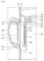
また、図26a、図26b及び図36a〜図36eによく示したように、光源部140はハウジング141の両端を閉鎖するように構成されるキャップ143を含むことができる。キャップ143は、基本的に水分又はその他の異物がハウジング141内に進入してモジュール142の故障を引き起こすことを防止することができる。キャップ143はヘッド143i及び上記ヘッド143iから伸びる延長部143aを含むことができる。ヘッド143iはハウジング141の外部に位置し、ブラケット121a、121bと結合されることができる。ヘッド143iは一部が開放した中空(hollow)の胴体を有することができる。すなわち、ヘッド143iは内部に所定の空間を形成するコンテナでなることができる。一部が開放しているので、ヘッド143iの内部空間はアクセス(access)可能である。よって、作業者は、ハウジング141の内部からキャップ143を通じて光源部140の外部に配線142c、142dを容易に引き出すことができる。その一方(in contrast)、延長部143aはハウジング141の内部に挿入されてモジュール142を保持することができる。すなわち、延長部143aはモジュール142を実質的に保持しながら(catching)支持する(supporting)ホルダとなることができる。ハウジング141の左右側端にキャップ143が取り付けられれば、延長部、つまりホルダ143aはモジュール142の左右側部を保持することができる。よって、このようなキャップ143、正確には延長部143aを用いて、モジュール142はハウジング141の内壁から一定の間隔を維持しながらハウジング141内で安定的に支持されることができる。 Further, as well shown in FIGS. 26a, 26b and 36a-36e, thelight source unit 140 can include acap 143 configured to close both ends of thehousing 141. Thecap 143 can basically prevent moisture or other foreign matter from entering thehousing 141 and causing a failure of themodule 142. Thecap 143 can include ahead 143i and anextension 143a extending from thehead 143i. Thehead 143i is located outside thehousing 141 and can be coupled to thebrackets 121a, 121b. Thehead 143i can have a hollow fuselage that is partially open. That is, thehead 143i can be a container that forms a predetermined space inside. The internal space of thehead 143i is accessible because part of it is open. Therefore, the operator can easily pull out thewirings 142c and 142d from the inside of thehousing 141 to the outside of thelight source unit 140 through thecap 143. On the other hand (in contrast), theextension 143a can be inserted inside thehousing 141 to hold themodule 142. That is, theextension 143a can serve as a supporting holder that substantially holds and supports themodule 142. If thecap 143 is attached to the left and right ends of thehousing 141, the extension portion, that is, theholder 143a can hold the left and right side portions of themodule 142. Therefore, by using such acap 143, more precisely, theextension portion 143a, themodule 142 can be stably supported in thehousing 141 while maintaining a constant distance from the inner wall of thehousing 141.

また、キャップ143は、図25にも示したように、キャップ143の胴体とハウジング141との間に配置されるシーリング部材143bをさらに含むことができる。実際的に、シーリング部材143bは上記延長部143aを取り囲むように配置される。シーリング部材143bはキャップ143、つまり延長部143aとハウジング141との間に押し込まれ、これによってハウジング141の内部に水分及びその他の異物が進入することを効果的に防止することができる。すなわち、上記シーリング部材143bは、ハウジング141と延長部143aとの間に挿入され、外部物質が上記ハウジング141内に進入することを防止する光源部140の第1シーリング部を形成することができる。また、キャップ143は突起(protrusion)143cを含むことができる。突起143cはキャップ143の左右側端から長手方向に外方に伸びることができる。図16〜図20にもよく示したように、ブラケット120は前方部に形成された溝121dを含むことができる。よって、図30a及び図30bによく示したように、突起143cを溝121dに挿入することにより、光源部140はブラケット120に結合され、安定的に支持されることができる。また、突起143cはブラケット120に直接結合され、ブラケット120の外部に露出される部位となる。したがって、このような突起143cを通じて配線142c、142dが受信部300と接続されるために、光源部140及びブラケット120の外部に引き出されることができる。このように引き出すために、突起143cは、図30a及び図30bによく示したように、貫通孔143hを含むことができる。受信部200の位置によって配線142c、142dは左右側突起143cのうち受信部200に近接したいずれか一つを通じて引き出されることができる。 Further, as shown in FIG. 25, thecap 143 can further include a sealingmember 143b arranged between the body of thecap 143 and thehousing 141. Practically, theceiling member 143b is arranged so as to surround theextension portion 143a. The sealingmember 143b is pushed between thecap 143, that is, theextension 143a and thehousing 141, which can effectively prevent moisture and other foreign matter from entering the inside of thehousing 141. That is, the sealingmember 143b can be inserted between thehousing 141 and theextension portion 143a to form a first sealing portion of thelight source portion 140 that prevents an external substance from entering thehousing 141. Also, thecap 143 can include aprotrusion 143c. Theprotrusion 143c can extend outward in the longitudinal direction from the left and right ends of thecap 143. As is well shown in FIGS. 16 to 20, thebracket 120 can include agroove 121d formed in the front portion. Therefore, as well shown in FIGS. 30a and 30b, by inserting theprotrusion 143c into thegroove 121d, thelight source unit 140 can be coupled to thebracket 120 and stably supported. Further, theprotrusion 143c is directly connected to thebracket 120 and becomes a portion exposed to the outside of thebracket 120. Therefore, since thewirings 142c and 142d are connected to the receivingunit 300 throughsuch protrusions 143c, they can be pulled out to the outside of thelight source unit 140 and thebracket 120. To pull out in this way, theprotrusion 143c can include a throughhole 143h, as well shown in FIGS. 30a and 30b. Depending on the position of the receivingunit 200, thewirings 142c and 142d can be pulled out through any one of the left andright side protrusions 143c that is close to the receivingunit 200.

一方、上記延長部143aは、前述したように、モジュール142を保持するホルダとしての機能を提供することができる。すなわち、キャップ143は、ハウジング141の内部に伸びてモジュール142を安定的に固定するように構成されるホルダ143aを含むことができる。上記ホルダ143aは図26a及び図26bによく示される。図26aはモジュール142と結合されたホルダ143aを示すが、図26bではホルダ143aをよりよく示すためにモジュール142が省略されている。図26a及び図26bを参照すると、キャップ143はモジュール142の両端を支持するように構成されるストッパ143dをホルダ143aとして有することができる。モジュール142は一般に所定の長さを有し、この長さは多様な条件、例えば含まれた素子142bの数によって決定できる。よって、モジュール142の長さが先に決定されるので、このようなモジュール142の両端と当接してこれらを支持するようにストッパ143dの大きさ、つまり長さも決定されることができる。上記ストッパ413dには貫通孔143kが形成され、ハウジング141の内部と外部とが上記貫通孔143kによって互いに連通することができる。したがって、配線142c、142dは貫通孔143kを通じてハウジング141の外部に引き出されることができ、このような貫通孔143kは図30a及び図30bにもよく示される。 On the other hand, theextension portion 143a can provide a function as a holder for holding themodule 142, as described above. That is, thecap 143 can include aholder 143a that extends inside thehousing 141 and is configured to stably secure themodule 142. Theholder 143a is often shown in FIGS. 26a and 26b. FIG. 26a shows theholder 143a coupled to themodule 142, but in FIG. 26b themodule 142 is omitted to better show theholder 143a. With reference to FIGS. 26a and 26b, thecap 143 may havestoppers 143d configured to support both ends of themodule 142 asholders 143a. Themodule 142 generally has a predetermined length, which can be determined by various conditions, for example the number ofelements 142b included. Therefore, since the length of themodule 142 is determined first, the size, that is, the length of thestopper 143d can be determined so as to abut and support both ends of themodule 142. A throughhole 143k is formed in the stopper 413d, and the inside and the outside of thehousing 141 can communicate with each other through the throughhole 143k. Therefore, thewirings 142c and 142d can be pulled out of thehousing 141 through the throughholes 143k, and such throughholes 143k are also well shown in FIGS. 30a and 30b.

また、キャップ143は、モジュール142の上部を支持するように構成される第1アーム(arm)143eをホルダ143aとして有することができる。第1アーム143eはモジュール142の上部を支持するようにモジュール142の上部に配置されることができる。より詳細には、第1アーム413eはストッパ143dの上部からハウジング141の内側に所定の長さで伸びることができる。また、キャップ143は、モジュール142の下部を支持するように構成される第2アーム(arm)143fをホルダ143aとして有することができる。第2アーム143fはモジュール142の下部を支持するようにモジュール142の下部に配置されることができる。より詳細には、第2アーム413fはストッパ143dの下部からハウジング141の内側に所定の長さで伸びることができる。また、モジュール142は長い胴体を持っているので、自重によって下方に垂れることがある。よって、第2アーム413fは、図示のように、第1アーム413eより長く形成されることができる。例えば、第2アーム413fは第1アーム413eの1.1倍〜3.0倍の長さを有することができる。また、第2アーム413fは部分的に縮小した幅を有するように構成されることができる。より詳細には、図26b及び図36a〜図36eによく示したように、第2アーム413fは、ヘッド143iから所定の長さで伸びる第1延長部143f−1、及び上記第1延長部143f−1から伸び、第1延長部143f−1より小さい幅を有する第2延長部143f−2を含むことができる。第1延長部143f−1は第1アーム143eとほぼ同じ長さを有することができ、これによって第2延長部143f−1が第2アーム413fの伸びた長さ(increased length)をなすようになる。よって、より単純な構造及び少ない素材を用いて第2アーム413fの意図した長さを確保することができる。このような第2アーム413fはモジュール142の下部のより広い部位を支持することができ、よって長いモジュール142を安定的に支持することができる。 Further, thecap 143 can have afirst arm 143e configured to support the upper portion of themodule 142 as theholder 143a. Thefirst arm 143e can be arranged on top of themodule 142 so as to support the top of themodule 142. More specifically, the first arm 413e can extend from the upper part of thestopper 143d to the inside of thehousing 141 by a predetermined length. Further, thecap 143 can have asecond arm 143f configured to support the lower portion of themodule 142 as theholder 143a. Thesecond arm 143f can be arranged in the lower part of themodule 142 so as to support the lower part of themodule 142. More specifically, the second arm 413f can extend from the lower part of thestopper 143d to the inside of thehousing 141 by a predetermined length. Also, since themodule 142 has a long fuselage, it may hang down due to its own weight. Therefore, the second arm 413f can be formed longer than the first arm 413e as shown in the figure. For example, the second arm 413f can have 1.1 to 3.0 times the length of the first arm 413e. Also, the second arm 413f can be configured to have a partially reduced width. More specifically, as well shown in FIGS. 26b and 36a to 36e, the second arm 413f includes afirst extension portion 143f-1 extending from thehead 143i by a predetermined length, and thefirst extension portion 143f. Asecond extension 143f-2 extending from -1 and having a width smaller than thefirst extension 143f-1 can be included. Thefirst extension 143f-1 can have approximately the same length as thefirst arm 143e so that thesecond extension 143f-1 has an increased length of the second arm 413f. Become. Therefore, the intended length of the second arm 413f can be secured by using a simpler structure and less material. Such a second arm 413f can support a wider portion of the lower part of themodule 142, and thus can stably support along module 142.

また、前述したように、基板の配線142c、142dはストッパ143dの貫通孔143kを通じてハウジング141の外部に伸びることができる。よって、上記貫通孔143kを通じて水分が浸透することができる。このような理由で、図30aによく示したように、キャップ143のヘッド143iはシーリング物質143gで充填されることができる。すなわち、上記シーリング物質143gはヘッド143iの内部に提供され、外部物質がハウジング141内に進入することを防止する光源部140の第2シーリング部を形成することができる。このようなシーリング物質143gはヘッド143i内で配線142c、142dを固定する役目もすることができる。また、図26aに示したように、水分及び外部物質によるモジュール142の故障をより効果的に防止するために、ホルダ143a、つまりストッパ143d並びに第1及び第2アーム143e、143fの内部及び/又は周りにさらにシーリング部材又は物質143mが提供されることができる。より詳細には、上記シーリング部材又は物質143mはホルダ143a(すなわち、ストッパ143d/第1及び第2アーム143e、143f)とモジュール142との間に挿入されることができ、水分又は他の外部物質がモジュール142に到逹することを効果的に遮断することができる。すなわち、前述した第1及び第2シーリング部143b、143gと一緒に、上記シーリング部材又はシーリング物質143mはホルダ143aとモジュール142との間に挿入され、外部物質が上記モジュール142に到逹することを防止する光源部140の第3シーリング部として作用することができる。このような更なるシーリング部材又は物質143mはストッパ143dの貫通孔143kもシーリングすることができる。したがって、ヘッド143i内のシーリング物質143g(図30a参照)が貫通孔143kを通じてハウジング141の内部に進入することも防止することができる。 Further, as described above, thewirings 142c and 142d of the substrate can extend to the outside of thehousing 141 through the throughhole 143k of thestopper 143d. Therefore, water can permeate through the throughhole 143k. For this reason, as well shown in FIG. 30a, thehead 143i of thecap 143 can be filled with 143 g of sealing material. That is, the sealingsubstance 143g is provided inside thehead 143i, and can form a second sealing portion of thelight source portion 140 that prevents an external substance from entering thehousing 141. Such a sealingsubstance 143g can also serve to fix thewirings 142c and 142d in thehead 143i. Further, as shown in FIG. 26a, in order to more effectively prevent the failure of themodule 142 due to moisture and external substances, theholder 143a, that is, thestopper 143d and the inside and / or the inside and / or of the first andsecond arms 143e and 143f. A sealing member ormaterial 143 m can be further provided around. More specifically, the sealing member orsubstance 143m can be inserted between theholder 143a (ie,stoppers 143d / first andsecond arms 143e, 143f) and themodule 142 to provide moisture or other external material. Can effectively block the arrival of themodule 142. That is, the sealing member or the sealingsubstance 143m is inserted between theholder 143a and themodule 142 together with the first andsecond sealing portions 143b and 143g described above, so that the external substance reaches themodule 142. It can act as a third sealing portion of thelight source portion 140 to be prevented. Such a further sealing member orsubstance 143m can also seal the throughhole 143k of thestopper 143d. Therefore, it is possible to prevent 143 g of the sealing substance (see FIG. 30a) in thehead 143i from entering the inside of thehousing 141 through the throughhole 143k.

このような光源部140は、図27に示したように、前方に光を照射するように構成されることができる。図25を参照すると、ハウジング141は前方部141a及び後方部141aを含むことができ、上記前方部141aが使用者に向かって配向されることができる。したがって、図27に示したように、発光素子142bは前方に光を照射するように前方に、つまり前方部141aに向かって配向されることができる。また、前方部141aのみが透明になって、照射された光を通過させることができる。このような光の照射は貯蔵室2を効果的に照明することができるが、使用者の眩しさを引き起こすことができる。このような理由で、光源部140は、図28に示したように、下方に光を照射するように構成されることができる。よって、図29にも示したように、発光素子142bは下方に光を照射するようにハウジング141の底部に向かって配向されることができる。また、照射された光を通過させるように構成されたウィンドウ141cがハウジング141の底部に形成されることができる。このような配向によって使用者に直接光が照射されず、眩しさを防止することができる。 As shown in FIG. 27, such alight source unit 140 can be configured to irradiate light forward. With reference to FIG. 25, thehousing 141 can include afront portion 141a and arear portion 141a, and thefront portion 141a can be oriented toward the user. Therefore, as shown in FIG. 27, thelight emitting element 142b can be oriented forward so as to irradiate light forward, that is, toward thefront portion 141a. Further, only thefront portion 141a becomes transparent so that the irradiated light can pass through. Such irradiation of light can effectively illuminate thestorage chamber 2, but can cause glare of the user. For this reason, thelight source unit 140 can be configured to irradiate light downward, as shown in FIG. Therefore, as shown in FIG. 29, thelight emitting element 142b can be oriented toward the bottom of thehousing 141 so as to irradiate light downward. Also, awindow 141c configured to allow the illuminated light to pass through can be formed at the bottom of thehousing 141. Due to such orientation, the user is not directly irradiated with light, and glare can be prevented.

より詳細には、図40aに示したように、光源部140は直下方に向かって光を照射するように構成されることができる。このような直下方への光の照射のために、光源部140は水平面に実質的に平行に配向されることができる。光を放出するウィンドウ141cが光源部140、正確にはハウジング141の底部に配置されるので、直下方に光を照射するために、光源部(すなわち、ハウジング141)の底部又はウィンドウ141cが上記水平面に実質的に平行に配向されることができる。一方、図40bに示したように、光源部140は下方だけでなく貯蔵室2の後方部にも光を照射するように構成されることができる。このために、光源部140は貯蔵室2の後方部に向かって配向されることができ、上記水平面に対して所定の傾斜角を有するように配向されることができる。より正確には、貯蔵室2の後方部にも光を照射するために、ハウジング141の底部又はウィンドウ141cが貯蔵室2の後方部に向かって配向されることができ、上記水平面に対して所定の傾斜角を有するように配向されることができる。 More specifically, as shown in FIG. 40a, thelight source unit 140 can be configured to irradiate light directly downward. Due to such irradiation of light directly below, thelight source unit 140 can be oriented substantially parallel to the horizontal plane. Since thewindow 141c that emits light is arranged at the bottom of thelight source unit 140, more precisely, thehousing 141, the bottom of the light source unit (that is, the housing 141) or thewindow 141c is the horizontal plane in order to irradiate the light directly below. Can be oriented substantially parallel to. On the other hand, as shown in FIG. 40b, thelight source unit 140 can be configured to irradiate not only the lower portion but also the rear portion of thestorage chamber 2. Therefore, thelight source unit 140 can be oriented toward the rear portion of thestorage chamber 2 and can be oriented so as to have a predetermined inclination angle with respect to the horizontal plane. More precisely, in order to irradiate the rear portion of thestorage chamber 2 with light, the bottom portion of thehousing 141 or thewindow 141c can be oriented toward the rear portion of thestorage chamber 2 and is predetermined with respect to the horizontal plane. Can be oriented to have a tilt angle of.

一方、前述したように、光源部140は、モジュール142、正確には発光素子142bを保護するハウジング141を含むが、光源部140はこのようなハウジング141なしにモジュール142を含むことができる。すなわち、光源部140は、外部に露出されたモジュール142、つまり発光素子142bを含むことができる。例えば、図27に示したように、露出された発光素子142bが光源部140として棚100に配置されることができ、前方に光を照射するように配向されることができる。一方、図28に示したように、露出された発光素子142bは光源部140として棚100に配置されることができ、下方に光を照射するように配向されることができる。このような露出された発光素子142bを有する光源部140にもこの明細書で説明する多様な光源部140の構成が同様に適用されることができる。 On the other hand, as described above, thelight source unit 140 includes thehousing 141 that protects themodule 142, to be exact, thelight emitting element 142b, but thelight source unit 140 can include themodule 142 without such ahousing 141. That is, thelight source unit 140 can include amodule 142 exposed to the outside, that is, alight emitting element 142b. For example, as shown in FIG. 27, the exposedlight emitting element 142b can be arranged on theshelf 100 as alight source unit 140, and can be oriented so as to irradiate light forward. On the other hand, as shown in FIG. 28, the exposedlight emitting element 142b can be arranged on theshelf 100 as alight source unit 140, and can be oriented so as to irradiate light downward. The various configurations of thelight source unit 140 described in this specification can be similarly applied to thelight source unit 140 having such an exposedlight emitting element 142b.

ウィンドウ141cが光源部140(すなわち、ハウジング141)の底部全体に形成されれば、光の放出面積の増加によって貯蔵室2の内部をより明るく照明することができる。しかし、このようなウィンドウ141cから放出された光の一部が前方に照射されて使用者に眩しさを引き起こす可能性がある。よって、図29及び光源部140の断面を示す図41a〜図41eに示したように、ウィンドウ141cはハウジング141の底部全体ではなくて一部にのみ形成されることができる。より詳細には、図41aに示したように、ウィンドウ141cの前端(front end)から後端(rear end)の間の長さ(A1)は光源部140(正確には、ハウジング141)の前端から後端までの距離(A2)の1/2に設定することができる。このようなウィンドウ141cの長さ(A2)の設定によって、眩しさを防止しながらも十分な照明を提供することができる。また、このようなウィンドウ141cがハウジング141の底部の前方部に配置されれば、前述したように、使用者の眩しさを引き起こすことができる。よって、図41a〜図41eに示したように、ウィンドウ141cはハウジング141の底部の後方部に配置されることができる。図41aのウィンドウ141c、つまりハウジング141の後方部に配置されたウィンドウ141cは眩しさを引き起こさないので、図40aに示したように、直下方に照射する光源部140に適用されることができる。一方、図40bの光源部140において、ウィンドウ141cが貯蔵室2の後方部に向かって配向されるので、このようなウィンドウ141cから照射された光は眩しさを引き起こす可能性が少ない。よって、図40bの光源部140はハウジング141の底部全体に形成されるウィンドウ141cを有することができる。また、発光素子142bは所定の間隔で離隔しているので、発光素子142bに近接したウィンドウ141cの一部はウィンドウ141cの他の部位に比べて相対的に明るくなることができる。すなわち、点光源として使用者に認識されることができる。このような現象は冷蔵庫の外観に影響を及ぼすことができる。このような理由で、ウィンドウ141cは入射する光を均一に分散させることができる拡散板(ディヒューザ)(diffuser)でなることができる。上記拡散板の使用によって点光源効果を除去することができる。 If thewindow 141c is formed on the entire bottom of the light source unit 140 (that is, the housing 141), the inside of thestorage chamber 2 can be illuminated more brightly by increasing the light emitting area. However, some of the light emitted from such awindow 141c may be radiated forward, causing glare to the user. Therefore, as shown in FIGS. 29a and 41e showing the cross section of thelight source unit 140, thewindow 141c can be formed only on a part of the bottom portion of thehousing 141, not the entire bottom portion. More specifically, as shown in FIG. 41a, the length (A1) between the front end and the rear end of thewindow 141c is the front end of the light source unit 140 (more precisely, the housing 141). It can be set to 1/2 of the distance (A2) from the rear end to the rear end. By setting the length (A2) of thewindow 141c in this way, it is possible to provide sufficient lighting while preventing glare. Further, if such awindow 141c is arranged in the front portion of the bottom portion of thehousing 141, it can cause glare of the user as described above. Therefore, as shown in FIGS. 41a to 41e, thewindow 141c can be arranged at the rear portion of the bottom portion of thehousing 141. Since thewindow 141c of FIG. 41a, that is, thewindow 141c arranged at the rear portion of thehousing 141 does not cause glare, it can be applied to thelight source unit 140 that irradiates directly below as shown in FIG. 40a. On the other hand, in thelight source unit 140 of FIG. 40b, since thewindow 141c is oriented toward the rear portion of thestorage chamber 2, the light emitted from such awindow 141c is unlikely to cause glare. Therefore, thelight source portion 140 of FIG. 40b can have awindow 141c formed on the entire bottom portion of thehousing 141. Further, since thelight emitting elements 142b are separated by a predetermined interval, a part of thewindow 141c close to thelight emitting element 142b can be relatively brighter than the other parts of thewindow 141c. That is, it can be recognized by the user as a point light source. Such a phenomenon can affect the appearance of the refrigerator. For this reason, thewindow 141c can be a diffuser capable of uniformly dispersing the incident light. The point light source effect can be removed by using the diffuser.

また、図41bに示したように、ウィンドウ141cは曲面状(curved)に形成されることができる。すなわち、ウィンドウ141cは実質的な曲率半径(R)を有するように形成されることができる。より詳細には、ウィンドウ141cは部分的に曲面状になることができ、これによって少なくとも一つの曲面部分(curved portion)を含むことができる。また、ウィンドウ141cは全体的に曲面状に形成されることができる。このような曲面状ウィンドウ141cによって光がより広い範囲に拡散することができ、貯蔵室2をより均一に照明することができる。光源部140が、前述したように、棚100の下側に位置する領域を照明するように構成されるので、モジュール142及び発光素子142bも、図41a及び図41bに示したように、下方に光を照射するように配向されることができる。すなわち、少なくとも発光素子142bはハウジング141の下方に向かって配向され、これによってハウジング141の下部内面と向き合うことができる。しかし、一方(alternatively)、図41cに示したように、モジュール142及び発光素子142bは下方に代わって上方に光を照射するように配向されることができる。すなわち、発光素子142bはハウジング141の上部に向かって配向されることができ、ハウジング141の上部内面と向き合うことができる。このような配向によって、発光素子142bはウィンドウ141cと向い合わないので、前述したような点光源現象を根本的に防止することができる。また、発光素子142bから放出された光は不透明なハウジング141の内面によって反射されながら拡散される(diffused)ことができ、よって、一次的にハウジング141の内部で均一な状態、つまり均一な光束(flux)を有することができる。したがって、このような均一な光がウィンドウ141cを通じて外部に放出されることにより、より均一な照明を行うことができる。また、図41dに示したように、上方に配向されたモジュール142及び発光素子142bは光源部140の後方部に配置されることができる。すなわち、発光素子142bはハウジング141の内部空間の後方部に配置されることができる。例えば、発光素子142bの垂直方向中心軸は光源部140(すなわち、ハウジング141)の垂直方向中心軸(C)から所定距離(B)で後方に離隔することができる。このような離隔距離(B)は、例えば約1mmであってもよい。このような発光素子142bは同様に後方部に配置されたウィンドウ141cと整列されることができる。よって、発光素子142bから放出された光はハウジング141の内面で反射され、直ちにウィンドウ141cに到逹されることができる。一方、図41eに示したように、モジュール142及び発光素子142bは光源部140、正確にはハウジング141の上部だけでなく前方部に向かって光を照射するように配向されることができる。すなわち、発光素子142bはハウジング141の上部内面及び前方内面と向き合うことができる。このような配向のために、発光素子142bは水平面に対して所定の角度(θ)で傾くことができる。例えば、上記角度(θ)は10°〜15°であってもよい。このように配向された発光素子142bは複数のハウジング141の内面と向き合うので、発光素子142bから放出された光はより大きく反射されて拡散することができる。例えば、図41a及び図41bに示した下方に配向された発光素子142bからの光の40%がハウジング141の内面で反射される反面、図41eの発光素子141bからの光の70%が上記内面で反射されることができる。よって、このような図41eの発光素子141bは点光源現象を防止しながらも著しく均一な照明を提供することができる。 Further, as shown in FIG. 41b, thewindow 141c can be formed in a curved shape (curved). That is, thewindow 141c can be formed to have a substantial radius of curvature (R). More specifically, thewindow 141c can be partially curved, which can include at least one curved portion. Further, thewindow 141c can be formed in a curved surface shape as a whole. With such acurved window 141c, the light can be diffused in a wider range, and thestorage chamber 2 can be illuminated more uniformly. Since thelight source unit 140 is configured to illuminate the area located below theshelf 100 as described above, themodule 142 and thelight emitting element 142b are also downward as shown in FIGS. 41a and 41b. It can be oriented to irradiate light. That is, at least thelight emitting element 142b is oriented downward of thehousing 141 so that it can face the lower inner surface of thehousing 141. However, on the other hand (alternatively), as shown in FIG. 41c, themodule 142 and thelight emitting element 142b can be oriented to illuminate upwards instead of downwards. That is, thelight emitting element 142b can be oriented toward the upper part of thehousing 141 and can face the upper inner surface of thehousing 141. Due to such orientation, thelight emitting element 142b does not face thewindow 141c, so that the above-mentioned point light source phenomenon can be fundamentally prevented. Further, the light emitted from thelight emitting element 142b can be diffused while being reflected by the inner surface of theopaque housing 141, so that the light is temporarily in a uniform state inside thehousing 141, that is, a uniform luminous flux (a uniform luminous flux). flux) can have. Therefore, by emitting such uniform light to the outside through thewindow 141c, more uniform illumination can be performed. Further, as shown in FIG. 41d, the upwardly orientedmodule 142 and thelight emitting element 142b can be arranged behind thelight source unit 140. That is, thelight emitting element 142b can be arranged at the rear portion of the internal space of thehousing 141. For example, the vertical central axis of thelight emitting element 142b can be separated rearward by a predetermined distance (B) from the vertical central axis (C) of the light source unit 140 (that is, the housing 141). Such a separation distance (B) may be, for example, about 1 mm. Such alight emitting element 142b can be aligned with thewindow 141c similarly arranged at the rear portion. Therefore, the light emitted from thelight emitting element 142b is reflected on the inner surface of thehousing 141 and can immediately reach thewindow 141c. On the other hand, as shown in FIG. 41e, themodule 142 and thelight emitting element 142b can be oriented so as to irradiate thelight source unit 140, more precisely, not only the upper portion of thehousing 141 but also the front portion. That is, thelight emitting element 142b can face the upper inner surface and the front inner surface of thehousing 141. Due to such orientation, thelight emitting element 142b can be tilted at a predetermined angle (θ) with respect to the horizontal plane. For example, the angle (θ) may be 10 ° to 15 °. Since thelight emitting element 142b oriented in this way faces the inner surfaces of the plurality ofhousings 141, the light emitted from thelight emitting element 142b can be more reflected and diffused. For example, 40% of the light from the downwardly oriented light emittingelement 142b shown in FIGS. 41a and 41b is reflected by the inner surface of thehousing 141, while 70% of the light from thelight emitting element 141b of FIG. 41e is the inner surface. Can be reflected by. Therefore, thelight emitting element 141b of FIG. 41e can provide remarkably uniform illumination while preventing the point light source phenomenon.

前述したように、棚部材110のプレート110a、つまり棚部材100の胴体は透明部材でなることができるので、光源部140から放出されるか冷蔵庫の他の部分で反射された光を通過させることができる。したがって、このようなプレート110aを通じての光の漏出によって、意図した空間を適切に照明することができない可能性がある。このような理由で、棚100は、棚部材110、正確にはプレート110aに形成されて光の漏出を防止するために、光を反射するように構成されるレイヤ(layer)114を含むことができる。図42はレイヤを含む棚部材を示す平面図である。また、図42は説明上の便宜のために棚部材110の下に配置された光源部140も一緒に示す。 As described above, since theplate 110a of theshelf member 110, that is, the body of theshelf member 100 can be made of a transparent member, the light emitted from thelight source unit 140 or reflected by other parts of the refrigerator is passed through. Can be done. Therefore, there is a possibility that the intended space cannot be properly illuminated due to the leakage of light through theplate 110a. For this reason, theshelf 100 may include ashelf member 110, more precisely alayer 114 formed on theplate 110a and configured to reflect light in order to prevent light leakage. it can. FIG. 42 is a plan view showing a shelf member including a layer. FIG. 42 also shows alight source unit 140 arranged under theshelf member 110 for convenience of explanation.

レイヤ114はプレート110aに入射する光が通過することができないように不透明に形成されることができる。また、このような不透明なレイヤ114はプレート110aに入射する光を反射することもできる。このようなレイヤ114はプレート110aの上面又は下面上に配置されることができる。また、レイヤ114は多様な方式で形成されることができる。例えば、レイヤ114は、プレート110aの上面又は下面上に印刷される不透明な塗料又はプレート110aの上面又は下面上に付着された不透明なフィルムでなることもできる。一般に、プレート110aの中央部には物品が載せられているので、光の漏出をこのような中央部では抑制することができる。したがって、レイヤ114は、図42に示したように、プレート110aの縁部に形成されることができる。より詳細には、レイヤ114は、プレート110aの前方部及び後方部にそれぞれ配置される前方及び後方レイヤ114a、114d、及びプレート110aの左右側にそれぞれ配置される左側及び右側レイヤ114b、114cを含むことができる。これらのレイヤ114a、114b、114c、114dは、外部に露出されて光を通過させ得るプレート110aの前後左右の端縁から内方に伸びることができる。したがって、プレート110aの縁部での光の露出を確かに防止することができる。特に、プレート110aの前方部には光源部140が配置されるので、光の漏出が上記プレート110aの前方部でひどく発生し得る。よって、前方レイヤ114aは、図42に示したように、プレート110aの前端からプレート110aの下側に配置された光源部140を覆うように伸びることができる。このような前方レイヤ114aによって光源部140が使用者に見えないので、光の漏出を防止しながらも棚100の外観を向上させることができる。同様に、左右側レイヤ114b、114cも左右側レール113a、113b及びブラケット121a、121bを使用者に見えないように遮ることができる。 Thelayer 114 can be formed opaque so that light incident on theplate 110a cannot pass through. In addition, such anopaque layer 114 can also reflect light incident on theplate 110a. Such alayer 114 can be arranged on the upper surface or the lower surface of theplate 110a. Further, thelayer 114 can be formed by various methods. For example, thelayer 114 may be an opaque paint printed on the upper or lower surface of theplate 110a or an opaque film adhered to the upper or lower surface of theplate 110a. Generally, since the article is placed in the central portion of theplate 110a, the leakage of light can be suppressed in such a central portion. Therefore, thelayer 114 can be formed on the edge of theplate 110a, as shown in FIG. 42. More specifically, thelayer 114 includes front andrear layers 114a and 114d arranged on the front and rear portions of theplate 110a, respectively, and left andright layers 114b and 114c arranged on the left and right sides of theplate 110a, respectively. be able to. Theselayers 114a, 114b, 114c, 114d can extend inward from the front, rear, left, and right edges of theplate 110a, which is exposed to the outside and allows light to pass through. Therefore, it is possible to certainly prevent the exposure of light at the edge of theplate 110a. In particular, since thelight source unit 140 is arranged in the front portion of theplate 110a, light leakage can occur severely in the front portion of theplate 110a. Therefore, as shown in FIG. 42, thefront layer 114a can extend from the front end of theplate 110a so as to cover thelight source unit 140 arranged below theplate 110a. Since thelight source unit 140 is not visible to the user due to such afront layer 114a, the appearance of theshelf 100 can be improved while preventing light leakage. Similarly, the left andright layers 114b and 114c can also block the left andright rails 113a and 113b and thebrackets 121a and 121b so that they cannot be seen by the user.

光源部140は、前述したように、棚100の前方部に配置され、下方に光を照射するように配向されることができる。このように意図した下方照明のために、光源部140は棚の上部をなす棚部材100より下側に配置されることが有利である。また、ブラケット121a、121bが棚部材100の下側に配置され、十分な強度を有するので、棚部材100の下側に配置される光源部140を支持するのに用いられることができる。したがって、光源部140は、例えば図16aに示したように、棚部材110の下側に配置され、棚100の前方部に配置されるように、ブラケット121a、121bの前方部の間に取り付けられることができる。一方、前述したように、前方バー122aも光源部140と同様にブラケット121a、121bの前方部に配置されるので、光源部140と前方バー122aとの多様な相対的配置を考慮することができる。これに関連し、図43a〜図43cは光源部及びブラケットのバー(bar)の多様な配置例を示す側面図である。まず、図43aに示したように、光源部140が前方バー122aの前方に配置されることができる。前方バー122aも棚100の前方部の強度を補強するためのものなので、光源部140と一緒にブラケット121a、121bの前方部に配置されるように、光源部140に近接して上記光源部140の後方に配置されることができる。一方(alternatively)、図43bに示したように、光源部140が前方バー122aの後側に配置されることができる。先に図43aで説明したものと類似した理由で、光源部140は貯蔵室2の前方部を照明するためのものなので、前方バー122aと一緒にブラケット121a、121bの前方部に配置されるように、前方バー122aに近接して上記前方バー122aの後方に配置されることができる。また、図43cに示したように、光源部140のみがブラケット121a、121bの前方部に配置されることができる。その代わりに、前方バー122aはブラケット121a、121bの前方部に提供されなくてもよい。 As described above, thelight source unit 140 is arranged in the front portion of theshelf 100 and can be oriented so as to irradiate light downward. For such intended downward illumination, it is advantageous that thelight source unit 140 is located below theshelf member 100 that forms the upper part of the shelf. Further, since thebrackets 121a and 121b are arranged on the lower side of theshelf member 100 and have sufficient strength, they can be used to support thelight source unit 140 arranged on the lower side of theshelf member 100. Therefore, thelight source unit 140 is arranged between the front portions of thebrackets 121a and 121b so as to be arranged below theshelf member 110 and arranged in the front portion of theshelf 100, for example, as shown in FIG. 16a. be able to. On the other hand, as described above, since thefront bar 122a is also arranged in the front portion of thebrackets 121a and 121b like thelight source portion 140, various relative arrangements between thelight source portion 140 and thefront bar 122a can be considered. .. In this regard, FIGS. 43a-43c are side views showing various arrangement examples of the light source unit and the bar of the bracket. First, as shown in FIG. 43a, thelight source unit 140 can be arranged in front of thefront bar 122a. Since thefront bar 122a is also for reinforcing the strength of the front portion of theshelf 100, thelight source portion 140 is located close to thelight source portion 140 so as to be arranged in the front portion of thebrackets 121a and 121b together with thelight source portion 140. Can be placed behind. On the other hand (alternatively), as shown in FIG. 43b, thelight source unit 140 can be arranged behind thefront bar 122a. Since thelight source unit 140 is for illuminating the front portion of thestorage chamber 2 for the same reason as that described above with reference to FIG. 43a, it is arranged in the front portion of thebrackets 121a and 121b together with thefront bar 122a. In addition, it can be arranged in the vicinity of thefront bar 122a and behind thefront bar 122a. Further, as shown in FIG. 43c, only thelight source portion 140 can be arranged in the front portion of thebrackets 121a and 121b. Instead, thefront bar 122a may not be provided on the front portion of thebrackets 121a, 121b.

このような多様な構成において、まず図43cの例において、光源部140は前方バー122aの代わりをするほどの十分な強度を有するように構成されることができる。例えば、光源部140のハウジング141は金属素材で作られ、十分な厚さ及び大きさを有することができ、よって光源部140が棚100の前方部に十分な強度を提供することができる。したがって、図43cの棚100は適切な強度を有しながらも単純な構造を有することができる。一方、図43aの例において、光源部140は前方バー122aの前方に配置されるので、光源部140から放出される光が前方バー122aによって遮られるか反射されないこともあり得る。したがって、前方バー122aとの干渉なしに、図43aの光源部140は意図した貯蔵室2の前方部をうまく照明することができる。また、光源部140自体もある程度の強度を棚100の前方部に提供することができるので、前方バー122aの追加によって棚100の強度をさらに補強することができる。結果的に、図43aの棚100は高強度を有しながらも意図した貯蔵室2の前方部を適切に照明することができ、本願の他の全ての図面もこのような図43aに示した光源部140及び前方バー122aの配置を含んでいる。 In such a variety of configurations, first, in the example of FIG. 43c, thelight source unit 140 can be configured to have sufficient intensity to replace thefront bar 122a. For example, thehousing 141 of thelight source unit 140 is made of a metal material and can have a sufficient thickness and size, so that thelight source unit 140 can provide sufficient strength to the front portion of theshelf 100. Therefore, theshelf 100 of FIG. 43c can have a simple structure while having appropriate strength. On the other hand, in the example of FIG. 43a, since thelight source unit 140 is arranged in front of thefront bar 122a, the light emitted from thelight source unit 140 may be blocked or not reflected by thefront bar 122a. Therefore, thelight source unit 140 of FIG. 43a can illuminate the intended front portion of thestorage chamber 2 well without interference with thefront bar 122a. Further, since thelight source unit 140 itself can provide a certain amount of strength to the front portion of theshelf 100, the strength of theshelf 100 can be further reinforced by adding thefront bar 122a. As a result, theshelf 100 of FIG. 43a can adequately illuminate the intended front portion of thestorage chamber 2 while having high intensity, and all other drawings of the present application are also shown in such FIG. 43a. The arrangement of thelight source unit 140 and thefront bar 122a is included.

このような図43aの配置例に関連し、光源部140及び前方バー122aは、使用者の便宜のために、より詳細に構成(configured)されることができる。図44は光源部及びバーの配置に関連した詳細な構成を示す側面図である。前述したように、棚部材110は前後方に移動可能に構成されることができる。棚部材110の前後方移動のために、使用者は棚部材110を引っ張るか押すことができる。このような操作を円滑に行うために、棚部材110に取っ手が必要とされることがあり得る。例えば、棚部材110の前方部、つまり前方カバー111が使用者に近く位置するので、このような前方カバー111が取っ手として用いられることができる。より詳細には、図16cにも示すように、棚100は棚部材110、正確には前方カバー111の下部に提供される取っ手111aを含むことができる。取っ手111aは、使用者が滑りなしに棚部材110を把持することができるように、多様な構造を有することができる。例えば、取っ手111aは、図16cに示したように、斜めに配置された複数のステップ部(step)でなることができる。また、使用者の手が取っ手111aを握るためには、棚100の前方部に配置された光源部140と取っ手111aとの間に空間が必要である。よって、光源部140は前方カバー110から所定間隔で離隔するように配置されることができる。より詳細には、光源部140の前端部は前方カバー110、正確には取っ手111aの後端部から所定距離(C1)で離隔することができる。例えば、上記離隔距離(C1)は3mm〜15mmであってもよい。このような離隔距離(C1)によって光源部140と取っ手111aとの間には使用者の把持のための十分な空間が提供されることができる。また、光源部140は棚100の前方部に配置されるので、使用者が棚部材110を移動させるために、取っ手111aの代わりに光源部140を引っ張ることができる。このような場合、光源部140はブラケット121a、121bに固定されているので、使用者の引っ張りによって破損されることがあり得る。よって、先に既に図43aを参照して説明したように、前方バー122bが光源部140の後方部に近接して配置されることができる。このような配置によって、前方バー122bと光源部140との間には使用者の手が入ることができる空間が形成されないので、光源部140が取っ手111aの代わりに使用者によって操作されることを防止することができる。その上、前方バー122bは光源部140より低く配置されることができる。前方バー122bが相対的に低く配置されるので、使用者が棚部材110の操作のために取っ手111aの代わりに他の部材を誤って握る場合にも、使用者は前方バー122bを光源部140の代わりに握ることができる。より詳細には、前方バー122aの下端部は光源部140の下端部より所定距離(C2)だけ低く配置されることができる。例えば、このような距離(C2)は1mm〜7mmであってもよい。このような距離(C2)による配置によって、前方バー122aは使用者によって光源部140の代わりに握られることができ、これによって光源部140の破損を防止することができる。 In connection with such an arrangement example of FIG. 43a, thelight source unit 140 and thefront bar 122a can be configured in more detail for the convenience of the user. FIG. 44 is a side view showing a detailed configuration related to the arrangement of the light source unit and the bar. As described above, theshelf member 110 can be configured to be movable forward and backward. The user can pull or push theshelf member 110 for forward and backward movement of theshelf member 110. A handle may be required on theshelf member 110 in order to smoothly perform such an operation. For example, since the front portion of theshelf member 110, that is, thefront cover 111 is located close to the user, such afront cover 111 can be used as a handle. More specifically, as also shown in FIG. 16c, theshelf 100 can include ashelf member 110, more precisely a handle 111a provided underneath thefront cover 111. The handle 111a can have a variety of structures so that the user can grip theshelf member 110 without slipping. For example, the handle 111a can consist of a plurality of diagonally arranged steps, as shown in FIG. 16c. Further, in order for the user's hand to grip the handle 111a, a space is required between thelight source unit 140 arranged in the front portion of theshelf 100 and the handle 111a. Therefore, thelight source unit 140 can be arranged so as to be separated from thefront cover 110 at a predetermined interval. More specifically, the front end of thelight source unit 140 can be separated from thefront cover 110, more precisely the rear end of the handle 111a, at a predetermined distance (C1). For example, the separation distance (C1) may be 3 mm to 15 mm. Such a separation distance (C1) can provide a sufficient space between thelight source unit 140 and the handle 111a for the user to grip. Further, since thelight source unit 140 is arranged in the front portion of theshelf 100, the user can pull thelight source unit 140 instead of the handle 111a in order to move theshelf member 110. In such a case, since thelight source unit 140 is fixed to thebrackets 121a and 121b, it may be damaged by the pull of the user. Therefore, as described above with reference to FIG. 43a, thefront bar 122b can be arranged close to the rear portion of thelight source unit 140. Due to such an arrangement, a space where the user's hand can enter is not formed between thefront bar 122b and thelight source unit 140, so that thelight source unit 140 is operated by the user instead of the handle 111a. Can be prevented. Moreover, thefront bar 122b can be arranged lower than thelight source unit 140. Since thefront bar 122b is arranged relatively low, even if the user mistakenly grasps another member instead of the handle 111a for operating theshelf member 110, the user can use thefront bar 122b as thelight source unit 140. Can be held instead of. More specifically, the lower end portion of thefront bar 122a can be arranged lower than the lower end portion of thelight source unit 140 by a predetermined distance (C2). For example, such a distance (C2) may be 1 mm to 7 mm. Due to the arrangement at such a distance (C2), thefront bar 122a can be gripped by the user instead of thelight source unit 140, whereby damage to thelight source unit 140 can be prevented.

前述した棚100の構造に続いて、冷蔵庫に適用された送信部200及び受信部300の実際的な構造を以下で関連図面に基づいて説明する。図21は本出願による冷蔵庫及び棚を示す部分斜視図、図22は棚のブラケット及び受信部を示す部分平面図、図23は貯蔵室側壁の送信部と棚の受信部との整列を説明する側面図である。特に、送信部200に関連しては、図31〜図35を以下で参照する。より詳細には、図31は送信部の側部を示す側面図、図32は送信部の背面を示す背面図である。図33は送信部の取付けのための構造を含むインナケースの部分斜視図である。最後に、図34a及び図34bは冷蔵庫に取り付けられた送信部及び受信部の多様な例を示す断面図、図35は冷蔵庫に取り付けられた送信部を示す部分斜視図である。また、図16〜図20は棚100の全体構造を詳細に示すので、以降の説明で一緒に参照する。 Following the structure of theshelf 100 described above, the practical structure of the transmittingunit 200 and the receivingunit 300 applied to the refrigerator will be described below with reference to the related drawings. FIG. 21 is a partial perspective view showing a refrigerator and a shelf according to the present application, FIG. 22 is a partial plan view showing a bracket and a receiving part of the shelf, and FIG. It is a side view. In particular, with respect to thetransmission unit 200, FIGS. 31 to 35 will be referred to below. More specifically, FIG. 31 is a side view showing a side portion of the transmission unit, and FIG. 32 is a rear view showing the back surface of the transmission unit. FIG. 33 is a partial perspective view of the inner case including a structure for mounting the transmitter. Finally, FIGS. 34a and 34b are cross-sectional views showing various examples of the transmitter and receiver attached to the refrigerator, and FIG. 35 is a partial perspective view showing the transmitter attached to the refrigerator. Further, since FIGS. 16 to 20 show the overall structure of theshelf 100 in detail, they will be referred to together in the following description.

送信部200は、前述したように、棚100に取り付けられた受信部300と向き合うように側壁15上に配置されることができる。図19、図21、図23、図31及び図32にそれぞれ示したように、送信部200は回路基板210でなることができる。また、送信部200は基板210上に形成されるコイル211を含むことができる。上記コイル211は送信部200、正確には基板210の受信部300と向き合う表面上に提供されることができる。より詳細には、コイル211は送信部200、正確には基板210の表面のうち受信部300に最も近い表面上に形成されることができる。このようなコイル211は電力伝送のための電磁波を発生させるもので、図2を参照して説明した1次コイルに相当することができる。 As described above, thetransmission unit 200 can be arranged on theside wall 15 so as to face thereception unit 300 attached to theshelf 100. As shown in FIGS. 19, 21, 23, 31 and 32, respectively, thetransmission unit 200 can be acircuit board 210. Further, thetransmission unit 200 can include acoil 211 formed on thesubstrate 210. Thecoil 211 can be provided on a surface facing the transmittingunit 200, more precisely the receivingunit 300 of thesubstrate 210. More specifically, thecoil 211 can be formed on the surface of thetransmitter 200, more precisely thesubstrate 210, which is closest to thereceiver 300. Such acoil 211 generates an electromagnetic wave for power transmission, and can correspond to the primary coil described with reference to FIG.

上記送信部200で発生する電磁波は受信部300に向かって送られる(移送される)(transmitted)が、一部の電磁波は反対方向に漏洩されることができる。よって、送信部200は、このような電磁波の漏洩を防止するための遮蔽部材212を含むことができる。図34bにもよく示すように、遮蔽部材212は受信部300と向き合う送信部200の表面と対向するように位置する送信部200の表面に提供されることができる。すなわち、送信部200は受信部300と向き合う第1表面、及び上記第1表面と対向する第2表面を含むことができ、遮蔽部材212はこのような第2表面上に付着されることができる。より詳細には、遮蔽部材212はコイル211が形成される表面の反対の表面上に直接付着されることができ、あるいはこのような反対表面に近接して配置されることができる。また、遮蔽部材212の代わりに遮蔽コーティングも同じ目的で適用することができる。遮蔽部材212は、電磁波が漏洩されることを防止するとともに、漏洩される電磁波、つまり受信部300の方ではなくて他方に配向された電磁波を再び受信部300に向かって実際的に迂回させるか再配向させることができる。したがって、送信部200の大部分の電磁波が受信部300に伝送されることができる。また、遮蔽部材212はコイル211のインダクタンスを増加させる役目もすることができる。このような遮蔽部材212によってより多量の電力が受信部300に効果的に伝送されることができる。また、送信部200は基板210に接続された端子213を含むことができる。このような端子213は、受信部300に電力を供給するために、外部電源と直接接続されることができる。また、上記貯蔵室2には、湿度が高くて水を含む食品がたくさん保管されるから、水が飛び出るか又は凝結する水滴が上記送信部200上で形成される(に結ぶ)(formed on)可能性がある。したがって、送信部200には防水コーティング214を適用することができる。すなわち、送信部200は、その内部に水分及びその他の異物が進入することを防止するように構成されるシーリング部材として上記防水コーティング214を含むことができる。図31に示したように、防水コーティング214は基板210上に適用されることができ、水分又はその他の異物が基板210に到逹することを防止することによって漏電又は感電を効果的に防止することができる。 The electromagnetic waves generated by the transmittingunit 200 are transmitted (transmitted) toward the receivingunit 300, but some electromagnetic waves can be leaked in the opposite direction. Therefore, thetransmission unit 200 can include a shieldingmember 212 for preventing such leakage of electromagnetic waves. As is well shown in FIG. 34b, the shieldingmember 212 can be provided on the surface of the transmittingunit 200 located so as to face the surface of the transmittingunit 200 facing the receivingunit 300. That is, the transmittingunit 200 can include a first surface facing the receivingunit 300 and a second surface facing the first surface, and the shieldingmember 212 can be attached to such a second surface. .. More specifically, the shieldingmember 212 can be attached directly on the opposite surface of the surface on which thecoil 211 is formed, or can be placed in close proximity to such an opposite surface. Further, instead of the shieldingmember 212, a shielding coating can be applied for the same purpose. Whether the shieldingmember 212 prevents the electromagnetic waves from being leaked and actually bypasses the leaked electromagnetic waves, that is, the electromagnetic waves oriented to the other side instead of the receivingunit 300, toward the receivingunit 300 again. It can be reoriented. Therefore, most of the electromagnetic waves of the transmittingunit 200 can be transmitted to the receivingunit 300. The shieldingmember 212 can also serve to increase the inductance of thecoil 211. A larger amount of electric power can be effectively transmitted to the receivingunit 300 by such a shieldingmember 212. Further, thetransmission unit 200 can include a terminal 213 connected to thesubstrate 210.Such terminals 213 can be directly connected to an external power source to supply power to the receivingunit 300. Further, since a large amount of food containing water due to high humidity is stored in thestorage chamber 2, water droplets from which water pops out or condenses are formed on thetransmitter 200. there is a possibility. Therefore, thewaterproof coating 214 can be applied to thetransmission unit 200. That is, thetransmission unit 200 can include thewaterproof coating 214 as a sealing member configured to prevent moisture and other foreign substances from entering the inside thereof. As shown in FIG. 31, thewaterproof coating 214 can be applied on thesubstrate 210 and effectively prevents electric leakage or electric shock by preventing moisture or other foreign matter from reaching thesubstrate 210. be able to.

受信部300は、前述したように、側壁15上に配置された送信部200と向き合うように棚100の左側部又は右側部、つまり左側ブラケット121a又は右側ブラケット121bに配置されることができる。図18に示したように、棚100を堅固に支持するために、ブラケット121a、121bの後方部はブラケット121a、121bの前方部より大きな大きさを有する。したがって、受信部300は相対的に広く、これによって適切な強度も有するブラケット121a、121bの後方部に配置されることができる。すなわち、受信部300はブラケット121a、121bの後端部から距離(L1)(の地点)までの(within a distance L1)後方部領域内に配置されることができる。このような距離(L1)は、例えばブラケット121a、121bの全長Lの1/4に設定することができる。したがって、受信部300はブラケット121a、121bの後端部から前方部の方に全長Lの1/4(地点)までの領域内に配置されることができる。 As described above, the receivingunit 300 can be arranged on the left side portion or the right side portion of theshelf 100, that is, theleft side bracket 121a or theright side bracket 121b so as to face the transmittingunit 200 arranged on theside wall 15. As shown in FIG. 18, the rear portions of thebrackets 121a and 121b have a larger size than the front portions of thebrackets 121a and 121b in order to firmly support theshelf 100. Therefore, the receivingunit 300 can be arranged at the rear portion of thebrackets 121a and 121b, which are relatively wide and thus have appropriate strength. That is, the receivingunit 300 can be arranged in the rear portion region (within a distance L1) from the rear end portions of thebrackets 121a and 121b to the distance (L1) (point). Such a distance (L1) can be set to, for example, 1/4 of the total length L of thebrackets 121a and 121b. Therefore, the receivingunit 300 can be arranged in the region from the rear end portion to the front portion of thebrackets 121a and 121b up to 1/4 (point) of the total length L.

図18〜図23にそれぞれ示したように、受信部300も回路基板310を含むことができる。また、受信部300は基板310上に形成されるコイル311を含むことができる。上記コイル311は、受信部300、正確には基板310の送信部200と向き合う表面上に提供されることができる。より詳細には、コイル311は、受信部300、正確には基板310の表面のうち送信部200に最も近い表面上に形成されることができる。このようなコイル311は図2を参照して説明した2次コイルに相当することができる。前述したように、送信部200のコイル211は受信部300と向き合う送信部200のいずれか一表面上に提供され、受信部300のコイル311も送信部200と向き合う受信部300のいずれか一表面上に提供されるので、上記コイル211、311は互いに向き合うようになり、効果的に電力を伝送することができる。 As shown in FIGS. 18 to 23, the receivingunit 300 can also include thecircuit board 310. Further, the receivingunit 300 can include acoil 311 formed on thesubstrate 310. Thecoil 311 can be provided on a surface facing the receivingunit 300, more precisely the transmittingunit 200 of thesubstrate 310. More specifically, thecoil 311 can be formed on the surface of the receivingunit 300, more precisely thesubstrate 310, which is closest to the transmittingunit 200. Such acoil 311 can correspond to the secondary coil described with reference to FIG. As described above, thecoil 211 of the transmittingunit 200 is provided on any one surface of the transmittingunit 200 facing the receivingunit 300, and thecoil 311 of the receivingunit 300 is also provided on any one surface of the receivingunit 300 facing the transmittingunit 200. As provided above, thecoils 211 and 311 face each other and can effectively transmit power.

送信部200で発生する電磁波は上記受信部300に大部分が伝達されることができるが、一部の電磁波は受信部300を通過して貯蔵室2内の貯蔵容器に伝達されることもあり得る。上記容器が金属素材などの電磁誘導を引き起こすことができる素材の容器であれば、上記容器が加熱されるに伴って容器に保管された食品の温度が上昇することができる。このような場合、上記容器内の食品はむしろ高温に加熱され、容易に(易しく)腐敗されるか変質されることがある。これを防止するために、受信部300は遮蔽部材312を含むことができる。したがって、送信部200から伝達される電磁波が食品容器を加熱することを防止することができる。図34bにもよく示すように、遮蔽部材312は送信部200と向き合う受信部300の表面と対向するように位置する受信部300の表面に提供されることができる。すなわち、受信部300は、送信部200と向き合う第1表面、及び上記第1表面と対向する第2表面を含むことができ、遮蔽部材312はこのような第2表面上に付着されることができる。より詳細には、遮蔽部材312はコイル311が形成される表面の反対の表面上に直接付着されることができ、あるいはこのような反対表面に近接して配置されることができる。また、遮蔽部材312の代わりに遮蔽コーティングも同じ目的で適用することができる。例えば、遮蔽部材312は基板310においてコイル311が形成される表面の反対側の表面上に付着されることができ、これに近接したブラケット120上に付着されることもできる。このような遮蔽部材312は、容器の誘導加熱を防止するだけでなく電磁波の漏洩を防止することによって電力受信効率を向上させることもできる。その上、遮蔽部材312はコイル311のインダクタンスを増加させることができ、これによって電力受信効率をより向上させることができる。また、図19、図20及び図22によく示したように、受信部300は光源部140の配線142c、142dと接続されることができる。より詳細には、受信部300の基板310が上記配線142c、142dと接続され、よって受信した電力が配線142c、142dを介してモジュール142に供給されることができる。また、送信部200と同様に、受信部300にも防水コーティングを適用することができ、漏電又は感電を効果的に防止することができる。すなわち、受信部300も、その内部に水分及びその他の異物が進入することを防止するように構成されるシーリング部材として上記防水コーティングを含むことができる。このような防水コーティングは基板310上に適用されることができ、水分又はその他の異物が基板310に到逹することを防止することによって漏電又は感電を効果的に防止することができる。 Most of the electromagnetic waves generated by the transmittingunit 200 can be transmitted to the receivingunit 300, but some electromagnetic waves may pass through the receivingunit 300 and be transmitted to the storage container in thestorage chamber 2. obtain. If the container is a container made of a material such as a metal material that can cause electromagnetic induction, the temperature of the food stored in the container can rise as the container is heated. In such cases, the food in the container is rather heated to a high temperature and can be easily (easily) spoiled or altered. In order to prevent this, the receivingunit 300 can include a shieldingmember 312. Therefore, it is possible to prevent the electromagnetic wave transmitted from the transmittingunit 200 from heating the food container. As is well shown in FIG. 34b, the shieldingmember 312 can be provided on the surface of the receivingunit 300 located so as to face the surface of the receivingunit 300 facing the transmittingunit 200. That is, the receivingunit 300 can include a first surface facing the transmittingunit 200 and a second surface facing the first surface, and the shieldingmember 312 may be attached to such a second surface. it can. More specifically, the shieldingmember 312 can be attached directly on the opposite surface of the surface on which thecoil 311 is formed, or can be placed in close proximity to such an opposite surface. Further, instead of the shieldingmember 312, a shielding coating can be applied for the same purpose. For example, the shieldingmember 312 can be attached to the surface of thesubstrate 310 opposite to the surface on which thecoil 311 is formed, and can also be attached to thebracket 120 in the vicinity thereof. Such a shieldingmember 312 can improve the power reception efficiency by not only preventing the induction heating of the container but also preventing the leakage of electromagnetic waves. Moreover, the shieldingmember 312 can increase the inductance of thecoil 311, which can further improve the power receiving efficiency. Further, as well shown in FIGS. 19, 20, and 22, the receivingunit 300 can be connected to thewirings 142c and 142d of thelight source unit 140. More specifically, thesubstrate 310 of the receivingunit 300 is connected to thewirings 142c and 142d, so that the received power can be supplied to themodule 142 via thewirings 142c and 142d. Further, similarly to the transmittingunit 200, the waterproof coating can be applied to the receivingunit 300, and it is possible to effectively prevent electric leakage or electric shock. That is, the receivingunit 300 can also include the waterproof coating as a sealing member configured to prevent moisture and other foreign substances from entering the inside thereof. Such a waterproof coating can be applied on thesubstrate 310 and can effectively prevent electric leakage or electric shock by preventing moisture or other foreign matter from reaching thesubstrate 310.

送信部200において、コイル211は、図21〜図23に示したように、上記側壁15に垂直な中心軸に対して半径が次第に増加する円形を成すように巻き付けられることができる。すなわち、コイル211は螺旋(渦巻き)形に(spirally)巻き付けられることができる。したがって、上記コイル211は同じ平面内に配置されることができる。また、受信部300でも同様にコイル311は螺旋形に巻き付けられ、同じ平面内に配置されることができる。したがって、このようなコイル211、311の構成によって、送信部200及び受信部300の厚さは大きく増加しなく、よって冷蔵庫内で大きな空間を占めない。また、図21〜図23でコイル211、311は円形を有するが、図19に示したように、楕円形を有することもできる。 In thetransmission unit 200, as shown in FIGS. 21 to 23, thecoil 211 can be wound so as to form a circular shape whose radius gradually increases with respect to the central axis perpendicular to theside wall 15. That is, thecoil 211 can be spirally wound. Therefore, thecoils 211 can be arranged in the same plane. Similarly, in the receivingunit 300, thecoil 311 can be wound in a spiral shape and arranged in the same plane. Therefore, such a configuration of thecoils 211 and 311 does not significantly increase the thickness of the transmittingunit 200 and the receivingunit 300, and thus does not occupy a large space in the refrigerator. Further, although thecoils 211 and 311 have a circular shape in FIGS. 21 to 23, they may also have an elliptical shape as shown in FIG.

このような楕円形コイル211、311は、効率的な電力伝送のために、より詳細な構成を含むことができる。図52は送信部の基板及びコイルの詳細な構成を示す平面図、図53は受信部の基板及びコイルの詳細な構成を示す平面図である。これらの図面及び関連の他の図面に基づき、コイル211、311とこれに関連した送受信部200、300の他の部品を以下でより詳細に説明する。 Suchelliptical coils 211 and 311 can include more detailed configurations for efficient power transfer. FIG. 52 is a plan view showing a detailed configuration of the substrate and the coil of the transmitting unit, and FIG. 53 is a plan view showing the detailed configuration of the substrate and the coil of the receiving unit. Based on these drawings and other related drawings, thecoils 211, 311 and other components of the transmitter /receiver 200, 300 related thereto will be described in more detail below.

楕円形コイル211、311は部分的に縮小した外径(例えば、最小外径(D2、D4))を有する。したがって、楕円形コイル211、311は、その配向によって、同じ直径(例えば、最大外径(D1、D3))を有する円形コイルより小さい水平又は垂直方向への幅を有することができる。すなわち、円形コイルに比べ、楕円形コイル211、311はコンパクトな外形(プロファイル)(profile)を有することができる。このような理由で、楕円形コイル211、311は効果的な電力伝送を行いながらも冷蔵庫内の限定された空間内に配置されるのに適することができる。また、受信部300の位置変化が発生する場合にも上記受信部300と継続的に向い合って安定的に電力を伝送するために、送信部200は受信部300より大きく形成されることができる。すなわち、送信部200のコイル211は受信部300のコイル311より大きく形成されることができる。しかし、冷蔵庫において、棚100は持続的に同じ位置に固定されるので、送受信部200、300の位置も所定の位置に特定され、持続的に維持されることができる。したがって、送信部200は受信部300より大きく形成される必要がない。このような理由で、送信部200は受信部300と実質的に同じ大きさを有することができる。すなわち、送信部200のコイル211と受信部300のコイル311とは同じ大きさの外形(outer profile)を有することができる。より詳細には、図19にも示したように、コイル211の外径(D1、D2)はコイル311の外径(D3、D4)と同一に形成されることができる。すなわち、コイル211の最大外径(D1)はコイル311の最大外径(D3)と同一であり、コイル211の最小外径(D2)はコイル311の最小外径(D4)と同一に設定されることができる。 Theelliptical coils 211 and 311 have a partially reduced outer diameter (eg, minimum outer diameters (D2, D4)). Therefore, theelliptical coils 211 and 311 can have a width in the horizontal or vertical direction smaller than that of a circular coil having the same diameter (for example, maximum outer diameters (D1, D3)) depending on the orientation. That is, theelliptical coils 211 and 311 can have a more compact profile than the circular coil. For this reason, theelliptical coils 211 and 311 can be suitable for being placed in a limited space within the refrigerator while providing effective power transfer. Further, even when the position of the receivingunit 300 changes, the transmittingunit 200 can be formed larger than the receivingunit 300 in order to continuously face the receivingunit 300 and stably transmit power. .. That is, thecoil 211 of the transmittingunit 200 can be formed larger than thecoil 311 of the receivingunit 300. However, in the refrigerator, since theshelves 100 are continuously fixed at the same position, the positions of the transmission /reception units 200 and 300 can also be specified at predetermined positions and can be continuously maintained. Therefore, the transmittingunit 200 does not need to be formed larger than the receivingunit 300. For this reason, the transmittingunit 200 can have substantially the same size as the receivingunit 300. That is, thecoil 211 of the transmittingunit 200 and thecoil 311 of the receivingunit 300 can have the same outer profile. More specifically, as shown in FIG. 19, the outer diameters (D1, D2) of thecoil 211 can be formed to be the same as the outer diameters (D3, D4) of thecoil 311. That is, the maximum outer diameter (D1) of thecoil 211 is the same as the maximum outer diameter (D3) of thecoil 311 and the minimum outer diameter (D2) of thecoil 211 is set to be the same as the minimum outer diameter (D4) of thecoil 311. Can be done.

このような構成によって、コイル211、311は次のような実際的な仕様(specification)を有することができる。まず、送信部200のコイル211において、最大外径(D1)は44mm、最小外径(D2)は33mmであってもよい。また、最大内径(d1)は30mm、最小内径(d2)は19mmであってもよい。コイル211のパターン(pattern)幅(W1)は1.0mmであってもよく、パターン間の間隔は0.2mmに設定されることができる。コイル211の厚さは70μmであってもよい。また、コイル211は実際的に積層された2層のレイヤでなることができ、各レイヤにおいてパターンの巻回数(すなわち、ターン数)は5.5ターン(turn)であってもよい。よって、全体的にパターンの巻回数は11ターンであってもよい。 With such a configuration, thecoils 211 and 311 can have the following practical specifications. First, in thecoil 211 of thetransmission unit 200, the maximum outer diameter (D1) may be 44 mm and the minimum outer diameter (D2) may be 33 mm. Further, the maximum inner diameter (d1) may be 30 mm and the minimum inner diameter (d2) may be 19 mm. The pattern width (W1) of thecoil 211 may be 1.0 mm, and the spacing between the patterns can be set to 0.2 mm. The thickness of thecoil 211 may be 70 μm. Further, thecoil 211 can be composed of two layers that are actually laminated, and the number of turns (that is, the number of turns) of the pattern in each layer may be 5.5 turns (turns). Therefore, the number of turns of the pattern may be 11 turns as a whole.

受信部300のコイル311において、最大外径(D3)は44mm、最小外径(D4)は33mmであってもよい。よって、前述したように、コイル211の外径(D1、D2)はコイル311の外径(D3、D4)と同一に形成される。また、最大内径(d3)は23mm、最小内径(d4)は12mmであってもよい。コイル311のパターン幅(W2)は0.6mmであってもよく、パターン間の間隔は0.2mmに設定されることができる。コイル311の厚さは70μmであってもよい。また、コイル211と同様に、コイル311も実際的に積層された2層のレイヤでなることができ、各レイヤにおいてパターンの巻回数(すなわち、ターン数)は13.5ターン(turn)であってもよい。よって、全体でパターンの巻回数は27ターンであってもよい。また、コイル311のインダクタンスは36.1±0.5μHであってもよく、DC抵抗は2.8±0.2Ωであってもよい。これらのインダクタンス及びDC抵抗は遮蔽部材312が取付けられたときの値である。 In thecoil 311 of the receivingunit 300, the maximum outer diameter (D3) may be 44 mm and the minimum outer diameter (D4) may be 33 mm. Therefore, as described above, the outer diameters (D1 and D2) of thecoil 211 are formed to be the same as the outer diameters (D3 and D4) of thecoil 311. Further, the maximum inner diameter (d3) may be 23 mm and the minimum inner diameter (d4) may be 12 mm. The pattern width (W2) of thecoil 311 may be 0.6 mm, and the spacing between the patterns can be set to 0.2 mm. The thickness of thecoil 311 may be 70 μm. Further, like thecoil 211, thecoil 311 can also consist of two layers that are actually laminated, and the number of turns (that is, the number of turns) of the pattern in each layer is 13.5 turns. You may. Therefore, the total number of turns of the pattern may be 27 turns. Further, the inductance of thecoil 311 may be 36.1 ± 0.5 μH, and the DC resistance may be 2.8 ± 0.2 Ω. These inductance and DC resistance are the values when the shieldingmember 312 is attached.

遮蔽部材212、312は、このようなコイル211、311から漏洩される電磁波及び磁束を遮断するために、上記コイル211、311の外形より大きな外形を有するように構成されることができる。遮蔽部材212、312も、他の図面、例えば、図17及び図19に示したように、最大及び最小直径を有する楕円形を有することができる。したがって、遮蔽部材212、312の最大直径はコイル211、311の最大直径(D1、D3)より大きく設定されることができる。また、遮蔽部材212、312の最小直径もコイル211、311の(外)最小直径(D2、D4)より大きく設定されることができる。例えば、遮蔽部材212、312の最大直径は46mm、最小直径は35mmに設定されることができる。このような遮蔽部材212、312は、接着剤、例えば両面テープによって基板210、310に付着されることができる。また、効果的な遮蔽のために、遮蔽部材212、312は強磁性体でなることができる。例えば、遮蔽部材212、312はμ(透磁率(permeability))>3000の強磁性体で製造されることができる。より詳細には、遮蔽部材212、312は強磁性体のうちフェライト(ferrite)、アモルファス物質などで作られることができる。フェライトを使う場合、Mn−Zn系又はNi−Zn系フェライトを使うことができる。Mn−Zn系フェライトは低損失に適し、Ni−Zn系フェライトは高周波に適する。 The shieldingmembers 212 and 312 can be configured to have an outer shape larger than the outer shape of thecoils 211 and 311 in order to block electromagnetic waves and magnetic fluxes leaked fromsuch coils 211 and 311. The shieldingmembers 212, 312 can also have an ellipse with maximum and minimum diameters, as shown in other drawings, eg, FIGS. 17 and 19. Therefore, the maximum diameter of the shieldingmembers 212 and 312 can be set larger than the maximum diameters (D1, D3) of thecoils 211 and 311. Further, the minimum diameter of the shieldingmembers 212 and 312 can also be set larger than the (outer) minimum diameters (D2 and D4) of thecoils 211 and 311. For example, the maximum diameter of the shieldingmembers 212 and 312 can be set to 46 mm, and the minimum diameter can be set to 35 mm. Such shieldingmembers 212 and 312 can be attached to thesubstrates 210 and 310 with an adhesive, for example, double-sided tape. Also, for effective shielding, the shieldingmembers 212 and 312 can be made of ferromagnets. For example, the shieldingmembers 212 and 312 can be made of a ferromagnet with μ (permeability)> 3000. More specifically, the shieldingmembers 212 and 312 can be made of a ferrite, an amorphous substance, or the like among ferromagnets. When ferrite is used, Mn—Zn-based or Ni—Zn-based ferrite can be used. Mn-Zn-based ferrite is suitable for low loss, and Ni-Zn-based ferrite is suitable for high frequency.

図21及び図23に示したように、送信部200は側壁15内に内蔵されることができる。したがって、このような送信部200は側壁15内に安定的に取り付けられることができるが、維持管理のために側壁15から分離しにくいこともあり得る。このような理由で、送信部200は側壁15から容易に脱着可能なモジュールで作られることができる。このようなモジュール化した送信部200を図31〜図32に示し、これらの図面に基づいて以下で詳細に説明する。 As shown in FIGS. 21 and 23, thetransmission unit 200 can be incorporated in theside wall 15. Therefore, such atransmission unit 200 can be stably mounted in theside wall 15, but may be difficult to separate from theside wall 15 for maintenance. For this reason, thetransmitter 200 can be made of a module that is easily removable from theside wall 15. Such amodularized transmission unit 200 is shown in FIGS. 31 to 32, and will be described in detail below based on these drawings.

まず、送信部200は、前述したように、コイル211、遮蔽部材212及び端子213が取り付けられた基板210を含むことができる。また、送信部200はこのような基板210を覆うカバー220を含むことができる。また、カバー220は上記基板210及びこれに取り付けられた他の部品を収容するように構成されることができる。より詳細には、カバー220は、図34a及び図34bによく示したように、胴体220aを有することができ、胴体220aは、平らな基板210を適切に支持するために、所定大きさのプレートでなることができる。カバー220は上記胴体220aから突出し、その縁部に沿って伸びる壁体(wall)221を有することができる。このような壁体221及び胴体220aによってカバー220は実質的に所定大きさのコンテナを形成することができる。したがって、形成された内部空間内に基板210及び他の部品を収容することができる。また、基板210は壁体221及び胴体220aによって安定的に支持されることができる。壁体221は、基板210を固定させるためのリブ211aをさらに含むこともできる。カバー220は胴体220aからさらに伸びるフランジ222を含むことができる。また、カバー220は壁体221からフランジ222と同一の方向に伸びるリブ223を含むことができる。このようなカバー220と基板210との結合によって送信部200がモジュール化されることができる。 First, as described above, thetransmission unit 200 can include thesubstrate 210 to which thecoil 211, the shieldingmember 212, and the terminal 213 are attached. Further, thetransmission unit 200 can include acover 220 that covers such asubstrate 210. Further, thecover 220 can be configured to accommodate thesubstrate 210 and other components attached to thesubstrate 210. More specifically, thecover 220 can have afuselage 220a, as well shown in FIGS. 34a and 34b, where thefuselage 220a is a plate of a predetermined size to properly support theflat substrate 210. Can be Thecover 220 may have awall 221 that projects from thefuselage 220a and extends along its edges. With such awall body 221 and abody body 220a, thecover 220 can form a container having a substantially predetermined size. Therefore, thesubstrate 210 and other components can be accommodated in the formed internal space. Further, thesubstrate 210 can be stably supported by thewall body 221 and thebody body 220a. Thewall body 221 may further include a rib 211a for fixing thesubstrate 210. Thecover 220 may include aflange 222 that extends further from thefuselage 220a. Further, thecover 220 can include arib 223 extending from thewall body 221 in the same direction as theflange 222. Thetransmission unit 200 can be modularized by such a combination of thecover 220 and thesubstrate 210.

図33を参照すると、モジュール化した送信部200を収容するために、インナケース10にはホール又はリセス200aが形成されることができる。図34aに示したように、インナケース10とアウタケース10aとの間は断熱材Sで満たされる。断熱材Sでケース10、10aの間が満たされるとき、静電気が発生し得る。断熱材Sで満たされる前に送信部200が取り付けられれば、静電気によって送信部200の回路が破損されることがあり得る。このような理由で、断熱材Sでケース10、10aの間が満たされた後、送信部200が取り付けられる。また、前もって満たされた断熱材Sが貯蔵室2内に進入することができないように送信部200を設置するための座部(seat)は底部が閉鎖されたリセス200aによって形成される。また、インナケース10の強度を補強するために、インナケース10の内面には補強板15aが取り付けられることができる。補強板15aにも送信部200の設置のための貫通孔200bが形成され、上記リセス200aと連通することができる。よって、図34aに示したように、送信部モジュール200をリセス200a内に挿入すれば、フランジ222は補強板15aの外面にかかり、リブ223は補強板15aの内面にかかることができる。同時に、送信部モジュール200の大部分はリセス200a内に配置され、外観を損なわないように、ただカバー210のみが、図35に示したように、外部に露出される。したがって、このような結合メカニズムによって送信部モジュール200は側壁15に安定的に付着されることができ、同じ方式で維持管理のために側壁15から容易に脱離されることができる。また、フランジ222が貫通孔200bより大きく形成されるので、外部の異物がリセス200a内に進入することができない。さらに、壁体221の周りにシーリング部材224が提供されることができ、よってリセス200aは、送信部200の故障を防止するために、より完全に密閉されることができる。また、断熱材Sが満たされる前に、外部電源と接続された配線がリセス200aに近接するように前もってケース10、10aの間に配置され、以後に満たされた断熱材Sによってケース10、10aの間に固定されることができる。したがって、送信部200がリセス200aに取り付けられるとき、上記リセス200aに近接した配線に送信部200の端子213が直ちに接続されることができ、送信部200と外部電源との間の接続が容易に行われることができる。上記外部電源に接続された配線の末端には、上記端子213と直接接続されるように構成された端子が取り付けられることができ、よって送信部200と外部電源とがより容易に接続されることができる。また、図34bに示したように、補強板15aは貫通孔200bの周りに形成されるリセス15bを含むことができる。フランジ200は上記リセス15b内に挿入され、補強板15aの外部に突出しないこともできる。より詳細には、フランジ200の外面は冷蔵庫の側壁15の表面と同一平面上に配置されることができる。よって、送信部200は冷蔵庫側壁15と実質的に一体化し、冷蔵庫の外観を向上させることができる。 Referring to FIG. 33, a hole or recess 200a may be formed in theinner case 10 to accommodate themodularized transmitter 200. As shown in FIG. 34a, the space between theinner case 10 and the outer case 10a is filled with the heat insulating material S. When the space between thecases 10 and 10a is filled with the heat insulating material S, static electricity may be generated. If thetransmitter 200 is attached before it is filled with the heat insulating material S, the circuit of thetransmitter 200 may be damaged by static electricity. For this reason, thetransmitter 200 is attached after the space between thecases 10 and 10a is filled with the heat insulating material S. Further, a seat for installing thetransmission unit 200 so that the pre-filled heat insulating material S cannot enter thestorage chamber 2 is formed by a recess 200a having a closed bottom. Further, in order to reinforce the strength of theinner case 10, a reinforcingplate 15a can be attached to the inner surface of theinner case 10. A throughhole 200b for installing thetransmission unit 200 is also formed in the reinforcingplate 15a, and can communicate with the recess 200a. Therefore, as shown in FIG. 34a, when thetransmission module 200 is inserted into the recess 200a, theflange 222 can be applied to the outer surface of the reinforcingplate 15a, and therib 223 can be applied to the inner surface of the reinforcingplate 15a. At the same time, most of thetransmitter module 200 is located in the recess 200a and only thecover 210 is exposed to the outside as shown in FIG. 35 so as not to spoil the appearance. Therefore, such a coupling mechanism allows thetransmitter module 200 to be stably attached to theside wall 15 and easily detached from theside wall 15 for maintenance in the same manner. Further, since theflange 222 is formed larger than the throughhole 200b, external foreign matter cannot enter the recess 200a. Further, a sealingmember 224 can be provided around thewall 221 so that the recess 200a can be more completely sealed to prevent failure of thetransmitter 200. Further, before the heat insulating material S is filled, the wiring connected to the external power supply is arranged in advance between thecases 10 and 10a so as to be close to the recess 200a, and the heat insulating material S filled thereafter is used to arrange thecases 10 and 10a. Can be fixed between. Therefore, when thetransmission unit 200 is attached to the recess 200a, theterminal 213 of thetransmission unit 200 can be immediately connected to the wiring close to the recess 200a, and the connection between thetransmission unit 200 and the external power supply can be easily performed. Can be done. At the end of the wiring connected to the external power supply, a terminal configured to be directly connected to the terminal 213 can be attached, so that thetransmitter 200 and the external power supply can be more easily connected. Can be done. Further, as shown in FIG. 34b, the reinforcingplate 15a can include arecess 15b formed around the throughhole 200b. Theflange 200 may be inserted into therecess 15b and may not protrude to the outside of the reinforcingplate 15a. More specifically, the outer surface of theflange 200 can be coplanar with the surface of theside wall 15 of the refrigerator. Therefore, thetransmission unit 200 can be substantially integrated with therefrigerator side wall 15 to improve the appearance of the refrigerator.

前述した送信部200と類似した理由で、受信部300もブラケット120に容易に着脱可能なモジュールとして作られることができる。このようなモジュール化した受信部300を図17〜図20に示し、これらの図面を参照して以下で詳細に説明する。参考として、図17〜図19は左側ブラケット121aに取り付けられる受信部300を示し、図20a及び図20bは右側ブラケット121bに取り付けられる受信部300を示す。 For the same reason as thetransmission unit 200 described above, thereception unit 300 can also be made as a module that can be easily attached to and detached from thebracket 120. Such amodularized receiving unit 300 is shown in FIGS. 17 to 20, and will be described in detail below with reference to these drawings. For reference, FIGS. 17 to 19 show a receivingunit 300 attached to theleft bracket 121a, and FIGS. 20a and 20b show a receivingunit 300 attached to theright bracket 121b.

まず、受信部300は、前述したように、コイル311、遮蔽部材312及び配線142c、142dが取り付けられた基板310を含むことができる。また、受信部300は、このような基板310を覆うカバー130を含むことができる。カバー130はやはり締結部材を用いてブラケット120に付着されることができ、よってブラケット120及びカバー130によって受信部300が取り囲まれることができる。したがって、カバー130は受信部300を外部環境から保護することができる。カバー130はブラケット120に付着されて棚100の一部を形成するので、棚100がこのようなカバー130を含むとも説明することができる。カバー130はやはり上記基板310及びこれに取り付けられた他の部品を収容するように構成されることができる。また、カバー130は、送信部200と受信部300との間の電力伝送及びこのための共振周波数の生成を邪魔しない素材で形成されることができる。例えば、カバー130はプラスチックなどの高分子素材及びその他の非伝導/非金属素材で作られることができる。 First, as described above, the receivingunit 300 can include thesubstrate 310 to which thecoil 311 and the shieldingmember 312 and thewirings 142c and 142d are attached. Further, the receivingunit 300 can include acover 130 that covers such asubstrate 310. Thecover 130 can also be attached to thebracket 120 using a fastening member, so that thebracket 120 and thecover 130 can surround thereceiver 300. Therefore, thecover 130 can protect the receivingunit 300 from the external environment. Since thecover 130 is attached to thebracket 120 to form a part of theshelf 100, it can also be described that theshelf 100 includes such acover 130. Thecover 130 can also be configured to accommodate thesubstrate 310 and other components attached thereto. Further, thecover 130 can be formed of a material that does not interfere with the power transmission between the transmittingunit 200 and the receivingunit 300 and the generation of the resonance frequency for this purpose. For example, thecover 130 can be made of a polymeric material such as plastic and other non-conducting / non-metallic materials.

より詳細には、図20a及び図20bによく示したように、カバー130は胴体130aを有することができる。上記胴体130aは板状部材でなることができ、上記胴体130aの縁部からこれに対してほぼ垂直にリブ130bが伸びることができる。よって、カバー130は胴体130a及びリブ130bによって受信部300の部品を収容する空間を形成することができる。また、カバー130は上記胴体130aから突出する壁体131を有することができる。このような壁体131及び胴体130aによってカバー130には所定大きさの座部(seat)131aが形成されることができる。よって、形成された座部131a内に基板310及び他の部品を収容することができる。また、配線142c、142dは、電源を供給するために、光源部140まで伸びなければならない。このような配線142c、142dを完全に保護するために、カバー130は、図示のように、ブラケット120の側面に沿って長く伸びることができ、図示したように、配線142c、142dもこのようなカバー130に沿って配置されることができる。カバー130はブラケット120の側面の外形と一致する外形を有することができ、よって棚100の外観を向上させることができる。 More specifically, as well shown in FIGS. 20a and 20b, thecover 130 can have afuselage 130a. Thebody 130a can be made of a plate-shaped member, and the rib 130b can extend from the edge of thebody 130a substantially perpendicular to the edge portion. Therefore, thecover 130 can form a space for accommodating the parts of the receivingunit 300 by thebody 130a and the rib 130b. Further, thecover 130 may have awall body 131 protruding from thebody body 130a. Such awall body 131 and abody body 130a can form aseat 131a having a predetermined size on thecover 130. Therefore, thesubstrate 310 and other components can be housed in the formedseat 131a. Further, thewirings 142c and 142d must extend to thelight source unit 140 in order to supply power. In order to completely protectsuch wirings 142c, 142d, thecover 130 can extend long along the side surface of thebracket 120, as shown, and as shown, thewirings 142c, 142d are also such. It can be placed along thecover 130. Thecover 130 can have an outer shape that matches the outer shape of the side surface of thebracket 120, thereby improving the appearance of theshelf 100.

また、カバー130は、配線142c、142dを保持するように構成された複数のリブ132を含むことができる。(配線は)このようなリブ132によってカバー130に安定的に付着されることができる。また、カバー130は、胴体130aに形成された複数のボス(boss)134を含むことができる。このようなボス134に対応し、図18に示したように、ブラケット121a、121bは複数の締結孔121eを含むことができる。その上、カバー130は胴体130aに形成される複数の突起135を含むことができる。図18に示したように、ブラケット121a、121bにはこのような突起135が挿入される複数のホール(hole)121fが形成されることができる。ブラケット121a、121bの後方部は、棚100を堅固に支持するために、これらの前方部より大きく形成されることができる。すなわち、ブラケット121a、121bの前方部は限定された空間を有する。よって、相対的に大きな大きさを有するボス134及び締結孔121eはカバー130及びブラケット121a、121bの後方部及び中央部に配置される反面、相対的に小さな大きさの突起135及びホール121fはカバー130及びブラケット121a、121bの前方部に配置されることができる。カバー130がブラケット121a又は121bに結合されるとき、まず突起135がホール121fに挿入されることにより、カバー130が正確な結合位置に配置されることができる。このような突起135及びホール121fの位置決め(positioning)によって、ボス134と締結孔121eとも互いに整列されることができる。締結部材を整列されたボス134及び締結孔121eに締結することにより、カバー130はブラケット121a、121bのいずれか一つに結合されることができる。 Thecover 130 may also include a plurality ofribs 132 configured to hold thewires 142c, 142d. (Wiring) can be stably attached to thecover 130 bysuch ribs 132. In addition, thecover 130 can include a plurality ofbosses 134 formed on thebody 130a. Corresponding to such aboss 134, as shown in FIG. 18, thebrackets 121a and 121b can include a plurality offastening holes 121e. Moreover, thecover 130 can include a plurality ofprotrusions 135 formed on thefuselage 130a. As shown in FIG. 18, a plurality ofholes 121f into whichsuch protrusions 135 are inserted can be formed in thebrackets 121a and 121b. The rear portions of thebrackets 121a, 121b can be formed larger than these front portions in order to firmly support theshelf 100. That is, the front portions of thebrackets 121a and 121b have a limited space. Therefore, theboss 134 and thefastening hole 121e having a relatively large size are arranged at the rear and central portions of thecover 130 and thebrackets 121a and 121b, while theprotrusion 135 and thehole 121f having a relatively small size cover thecover 130 and thebrackets 121a and 121b. It can be arranged in front of the 130 and thebrackets 121a, 121b. When thecover 130 is coupled to thebracket 121a or 121b, thecover 130 can be placed in the correct coupling position by first inserting theprotrusion 135 into thehole 121f. By such positioning of theprotrusion 135 and thehole 121f, theboss 134 and thefastening hole 121e can also be aligned with each other. By fastening the fastening member to the alignedboss 134 and thefastening hole 121e, thecover 130 can be coupled to any one of thebrackets 121a and 121b.

前述したカバー130と基板310との結合、つまり基板310の座部131aへの挿入によって、送信部300はカバー130とモジュール化することができ、カバー130と一緒に容易にブラケット120に取付けられるかあるいは分離されることができる。また、配線142c、142dはカバー130に沿って配列され、その端部に形成された開口部(aperture)133を通じてカバー130の外部に引き出され、突起143cによってモジュール142と接続されることができる。したがって、図18、図20、及び図30に示したように、カバー130、受信部300及び光源部140は単一のモジュール又はアセンブリを形成することができる。このようなアセンブリにおいて、棚100全体の観点で(With regard to the entire shelf 100)、受信部300は、これを収容するカバー130の一部と一緒に、図20aに示したように、受信部(R)を形成することができる。また、配線142c、142dは、これを収容するカバー130の一部と一緒に、配線部Wを形成することができる。光源部140は配線部Wによって電源を受ける負荷として見なされることができる。このようなアセンブリとして、カバー130、送信部300及び光源部140は、棚100、正確にはブラケット120に一度に(at the same time)容易に取り付けられることができ、しかも、維持管理のために容易に分離されることができる。カバー130は前述したようなソリッドな(solid)部材以外に他の形態でも具現されることができる。例えば、ブラケット121a、121b上に受信部300及び配線142c、142dを配置し、前述したような電力伝送を邪魔しない物質をブラケット121a、121b、受信部300及び配線142c、142d上に塗布することができる。すなわち、ソリッドなカバー130の代わりに塗料又は他のフレキシブルな部材がカバー130と同一の機能を行うように用いられることができる。このようなカバーの他の例は、同様に、電力伝送及び共振周波数生成を邪魔しないとともに、ブラケット121a、121bに受信部300及び配線142c、142dを固定させ、受信部300及び配線142c、142dを外部物質から保護することができる。 By combining thecover 130 and thesubstrate 310 described above, that is, inserting thesubstrate 310 into theseat 131a, thetransmitter 300 can be modularized with thecover 130 and can be easily attached to thebracket 120 together with thecover 130. Alternatively, it can be separated. Further, thewirings 142c and 142d are arranged along thecover 130, are drawn out of thecover 130 through an opening (aperture) 133 formed at the end thereof, and can be connected to themodule 142 by theprotrusion 143c. Therefore, as shown in FIGS. 18, 20, and 30, thecover 130, thereceiver 300, and thelight source 140 can form a single module or assembly. In such an assembly, with regard to theentire shelf 100, thereceiver 300, along with a portion of thecover 130 that accommodates it, is the receiver, as shown in FIG. 20a. (R) can be formed. Further, thewirings 142c and 142d can form the wiring portion W together with a part of thecover 130 for accommodating the wirings 142c and 142d. Thelight source unit 140 can be regarded as a load that receives power from the wiring unit W. As such an assembly, thecover 130, thetransmitter 300 and thelight source 140 can be easily attached to theshelf 100, more precisely thebracket 120 at the same time, for maintenance purposes. It can be easily separated. Thecover 130 can be embodied in other forms besides the solid member as described above. For example, the receivingunits 300 and thewirings 142c and 142d may be arranged on thebrackets 121a and 121b, and a substance that does not interfere with power transmission as described above may be applied onto thebrackets 121a and 121b, the receivingunits 300 and thewirings 142c and 142d. it can. That is, instead of thesolid cover 130, paint or other flexible member can be used to perform the same function as thecover 130. Similarly, another example of such a cover does not interfere with power transmission and resonance frequency generation, and the receivingunits 300 andwirings 142c and 142d are fixed to thebrackets 121a and 121b, and the receivingunits 300 andwirings 142c and 142d are connected. It can be protected from external substances.

一方、前述したように、棚100は相異なる高さを有するように上方及び下方に移動することができる。上記棚100の光源部140に電源を供給するためには、送信部200と受信部300とが互いに向き合わなければならない。したがって、棚100の移動後にも互いに向き合うように送信部200及び受信部300のいずれか一つが調節される必要がある。しかし、受信部300は棚100に固定されて一緒に移動するので、受信部300の代わりに送信部200が互いに向き合うように調節される必要がある。よって、送信部200は、棚100が上方又は下方に移動した後にも受信部300とずっと向き合うように構成されることができる。このような送信部200と受信部300との間の対面配置(face-to-face arrangement)のために、多様な構造を適用することができる。例えば、図21及び図23に示したように、複数の送信部200が側壁15に相異なる高さに配置されることができる。より詳細には、棚100が配置可能な高さと同一の高さに送信部200がそれぞれ配置されることができる。また、前述したように、互いに隣り合う装着孔18にかかる第1及び第2係止片123a、123bによって、棚100が後壁13に固定されることができる。図23及び図34に示すように、固定された棚100のブラケット120は装着孔18の間に配置され、このようなブラケット120の側面に配置された受信部300も同様に装着孔18の間に配置されることができる。よって、図23に示したように、複数の送信部200は互いに隣り合う装着孔18の間の高さ(H)で側壁15に配置されることができる。すなわち、送信部200は、互いに隣り合う装着孔18の間に、つまり距離(H)内に配置されるように、冷蔵庫の側壁15に取り付けられることができる。このような理由で、図23(a)に示したいずれか一つの高さから図23(b)に示した他の高さに棚100が移動する場合にも、受信部300と送信部200とが安定的な電力伝送のために向き合うことができる。また、より高い電力伝送効率のために、棚100の高さが変更された後にも送信部及び受信部200、300のコイル211、311が図示のように互いに向き合うことができる。また、棚100の高さが変更された後にも上記コイル211、311の中心軸がより高い電力伝送のために互いに一致するように配置されることもできる。また、係止片123a、123b及び装着孔18の構造が図23に示したものとは違うように変更されれば、互いに向き合うように側壁15及びブラケット120にそれぞれ配置された送信部200及び受信部300はそれ以上装着孔18の間に配置されないこともあり得る。例えば、図23に示したブラケット120の後端の上部及び下端にそれぞれ配置される係止片123a、123bとは違い、上記係止片123a、123bのいずれか一つがブラケット120の後端中央部に配置されれば、装着孔18間の距離(H)もこのような係止片123a、123bの変更によって減少することができる。よって、受信部300と向き合う送信部200はそれ以上上記距離(H)内に配置されることができないことがあり得る。しかし、このような場合にも、受信部300は依然としてブラケット120の側部に配置される。よって、送信部200の全部又は少なくとも送信部200の一部がブラケット120の側部と向き合うように側壁15に配置されれば、より詳細には、上記ブラケット120の上端部と下端部との間に配置されれば、このような送信部200は係止片123a、123b及び装着孔18の構成の変化に関係なく(構わず)(regardless of)、ブラケット120の側部に配置された受信部300と向き合うことができる。 On the other hand, as described above, theshelves 100 can be moved upwards and downwards so as to have different heights. In order to supply power to thelight source unit 140 of theshelf 100, thetransmission unit 200 and thereception unit 300 must face each other. Therefore, it is necessary to adjust any one of the transmittingunit 200 and the receivingunit 300 so as to face each other even after theshelves 100 are moved. However, since the receivingunit 300 is fixed to theshelf 100 and moves together, it is necessary to adjust the transmittingunit 200 so as to face each other instead of the receivingunit 300. Therefore, the transmittingunit 200 can be configured to face the receivingunit 300 all the time even after theshelf 100 has moved upward or downward. Various structures can be applied for such a face-to-face arrangement between the transmittingunit 200 and the receivingunit 300. For example, as shown in FIGS. 21 and 23, a plurality oftransmitters 200 can be arranged on theside wall 15 at different heights. More specifically, thetransmission units 200 can be arranged at the same height as theshelves 100 can be arranged. Further, as described above, theshelf 100 can be fixed to therear wall 13 by the first andsecond locking pieces 123a and 123b that extend to the mountingholes 18 adjacent to each other. As shown in FIGS. 23 and 34, thebracket 120 of the fixedshelf 100 is arranged between the mountingholes 18, and the receivingunit 300 arranged on the side surface of such abracket 120 is also arranged between the mounting holes 18. Can be placed in. Therefore, as shown in FIG. 23, the plurality oftransmission units 200 can be arranged on theside wall 15 at a height (H) between the mountingholes 18 adjacent to each other. That is, thetransmission unit 200 can be attached to theside wall 15 of the refrigerator so as to be arranged between the mountingholes 18 adjacent to each other, that is, within the distance (H). For this reason, even when theshelf 100 moves from any one height shown in FIG. 23 (a) to the other height shown in FIG. 23 (b), the receivingunit 300 and the transmittingunit 200 Can face each other for stable power transmission. Further, for higher power transmission efficiency, thecoils 211 and 311 of the transmitting unit and the receivingunits 200 and 300 can face each other as shown even after the height of theshelf 100 is changed. Further, even after the height of theshelf 100 is changed, the central axes of thecoils 211 and 311 can be arranged so as to coincide with each other for higher power transmission. Further, if the structures of the lockingpieces 123a and 123b and the mountinghole 18 are changed so as to be different from those shown in FIG. Theportion 300 may not be further arranged between the mounting holes 18. For example, unlike the lockingpieces 123a and 123b arranged at the upper and lower ends of the rear end of thebracket 120 shown in FIG. 23, any one of the lockingpieces 123a and 123b is the central portion of the rear end of thebracket 120. The distance (H) between the mountingholes 18 can also be reduced by such a change of the lockingpieces 123a and 123b. Therefore, the transmittingunit 200 facing the receivingunit 300 may not be able to be arranged within the above distance (H) any more. However, even in such a case, the receivingunit 300 is still arranged on the side portion of thebracket 120. Therefore, if all or at least a part of thetransmission unit 200 is arranged on theside wall 15 so as to face the side portion of thebracket 120, more specifically, between the upper end portion and the lower end portion of thebracket 120. When arranged in, such atransmitter 200 is a receiver located on the side of thebracket 120, regardless of changes in the configuration of the lockingpieces 123a, 123b and the mountinghole 18. You can face 300.

図23に示したように、前述したような構成を有する複数の送信部200を形成するために、単一基板210上に複数のコイル211が配置されることができる。図23の送信部200の代わりに、図31〜図35に示したように、複数のモジュール化した送信部200が提供されることができる。また、前述した複数の送信部200の代わりに、単一送信部200が側壁15上に垂直方向にスライド可能に取り付けられることができる。したがって、このような送信部200は、変化する棚100及び受信部300の高さに合わせて自体の高さを調節することができる。また、図23に示したように、単一基板210上に受信部300が配置されることができる高さの全体にわたって(かけて)(over)単一のコイル211aが配置されることができる。よって、受信部300の高さが棚100と一緒に変化しても、いつも送信部200は受信部300と向き合うことができるようになる。一方、受信部300の位置は装着孔18によって決定される。したがって、送信部200の位置が先に決定され、このような既に設定された位置の送信部200と受信部300とが、棚100の高さが変更された後にも、互いに向き合うように、装着孔18の高さが調節されることもできる。 As shown in FIG. 23, a plurality ofcoils 211 can be arranged on asingle substrate 210 in order to form a plurality oftransmission units 200 having the above-described configuration. As shown in FIGS. 31 to 35, a plurality ofmodularized transmission units 200 can be provided instead of thetransmission unit 200 of FIG. 23. Further, instead of the plurality oftransmission units 200 described above, asingle transmission unit 200 can be vertically slidably mounted on theside wall 15. Therefore, such atransmission unit 200 can adjust its own height according to the changing heights of theshelf 100 and thereception unit 300. Also, as shown in FIG. 23, a single coil 211a can be placed over the entire height at which thereceiver 300 can be placed on thesingle substrate 210. .. Therefore, even if the height of the receivingunit 300 changes together with theshelf 100, the transmittingunit 200 can always face the receivingunit 300. On the other hand, the position of the receivingunit 300 is determined by the mountinghole 18. Therefore, the position of the transmittingunit 200 is determined first, and the transmittingunit 200 and the receivingunit 300 at such already set positions are mounted so as to face each other even after the height of theshelf 100 is changed. The height of theholes 18 can also be adjusted.

電磁誘導方式による電力伝送において、送信部200と受信部300とが互いに遠くなれば、電力伝送効率が減少することができる。よって、送信部200と受信部300とは互いに接触するように配置されることが好ましい。しかし、図34を参照すると、断熱材Sはインナ及びアウタケース10、10aの間に高圧で充填されるので、これらのケース10、10aに高圧を加えることになる。よって、インナケース10、つまり側壁15が突出することができ、設計されたものとは違う寸法を有することができる。送信部200と受信部300とが互いに接触するように設計されれば、このような生産工程中の寸法変更によって送信部200が受信部300を押圧して破損を引き起こすことができる。また、前述したように、棚100は垂直及び水平方向に移動する。よって、送信部200と受信部300とが互いに接触するように設計されれば、棚100の着脱時、側壁15又は棚100に損傷が加えられることもできる。よって、図34に示したように、送信部200と受信部300とは一定の距離(t)で互いに離隔することができる。すなわち、送信部200と受信部300とは互いに直接接触しないように構成される。上記距離(t)は電力伝送効率を大きく低下させないように設定され、およそ9mm程度に設定されることができる。一方、既存の有線電力伝送方式は棚100とインナケース10との直接的な接触を必要とするので、腐食、漏電及び感電などの理由に加え、前述した寸法変更及び損傷などの問題点をさらに内包することになる。よって、このような理由を考慮するとき、無線電力伝送技術に基づく送信部200及び受信部300を適用することが冷蔵庫棚100の光源に電源を供給するのに最適であることがより明確になることができる。 In power transmission by the electromagnetic induction method, if the transmittingunit 200 and the receivingunit 300 are far from each other, the power transmission efficiency can be reduced. Therefore, it is preferable that the transmittingunit 200 and the receivingunit 300 are arranged so as to be in contact with each other. However, referring to FIG. 34, since the heat insulating material S is filled with high pressure between the inner andouter cases 10 and 10a, a high pressure is applied to thesecases 10 and 10a. Therefore, theinner case 10, that is, theside wall 15 can be projected, and can have dimensions different from those designed. If the transmittingunit 200 and the receivingunit 300 are designed to be in contact with each other, the transmittingunit 200 can press the receivingunit 300 and cause damage due to such a dimensional change during the production process. Further, as described above, theshelf 100 moves in the vertical and horizontal directions. Therefore, if the transmittingunit 200 and the receivingunit 300 are designed to be in contact with each other, theside wall 15 or theshelf 100 can be damaged when theshelf 100 is attached or detached. Therefore, as shown in FIG. 34, the transmittingunit 200 and the receivingunit 300 can be separated from each other at a certain distance (t). That is, the transmittingunit 200 and the receivingunit 300 are configured so as not to come into direct contact with each other. The distance (t) is set so as not to significantly reduce the power transmission efficiency, and can be set to about 9 mm. On the other hand, since the existing wired power transmission method requires direct contact between theshelf 100 and theinner case 10, in addition to the reasons such as corrosion, electric leakage and electric shock, the above-mentioned problems such as dimensional change and damage are further added. It will be included. Therefore, when considering such a reason, it becomes clearer that the application of thetransmission unit 200 and thereception unit 300 based on the wireless power transmission technology is optimal for supplying power to the light source of therefrigerator shelf 100. be able to.

先に参照した全ての図面に示したように、受信部300は配線142c、142dを介して光源部140と電気的に接続され、送信部200から伝送された電力を光源部140に供給することができる。一方、棚100はこのような配線142c、142dを介した電気的接続とは違う電気的接続を変形例として含むことができる。これに関連し、図45は受信部と光源部との電気的接続の変形例を示す斜視図である。棚の構成はもう既に前述したので、以下では構成の異なる点(区別される構成)(differences in configuration)のみを説明する。同じ理由で、説明しなかった構成に対しては、先に他の図面を参照して説明した構成を同様に適用し、これについての詳細な説明はやはり省略する。 As shown in all the drawings referred to above, the receivingunit 300 is electrically connected to thelight source unit 140 via thewirings 142c and 142d, and supplies the power transmitted from the transmittingunit 200 to thelight source unit 140. Can be done. On the other hand, theshelf 100 can include an electrical connection different from the electrical connection via thewirings 142c and 142d as a modification. In this regard, FIG. 45 is a perspective view showing a modified example of the electrical connection between the receiving unit and the light source unit. Since the shelf configuration has already been described above, only the differences in configuration will be described below. For the same reason, the configuration described above with reference to other drawings is similarly applied to the configuration not described, and the detailed description thereof will also be omitted.

図45に示した変形例は、配線142c、142dの代わりに、ブラケット121aを受信部300と光源部140との電気的接続のために使うことができる。もう既に説明したように、送信部200及び受信部300の構造と上記送信部200から受信部300への電力伝送のための構成とは前述したものと同一である。まず、棚100は、ブラケット121aと受信部300とを電気的に接続する第1接続部124を含むことができる。より詳細には、第1接続部124はブラケット121aに提供され、受信部300と接続される第1及び第2接点124a、124bを含むことができる。また、上記第1及び第2接点124a、124bは配線124c、124dを介して受信部300、正確には基板310と電気的に接続されることができる。一方、棚100は、ブラケット121aと光源部140とを電気的に接続する第2接続部125を含むことができる。より詳細には、第2接続部125はブラケット121aに提供され、光源部140と接続される第1及び第2接点125a、125bを含むことができる。また、上記第1及び第2接点125a、125bは配線125c、125dを介して光源部140、正確にはモジュール142と電気的に接続されることができる。また、上記第1及び第2接続部125の間の電気的接続のために、ブラケット121aの胴体が用いられることができる。このような電気的接続のために、ブラケット121aは高伝導性素材、例えば鋼鉄でなることができる。すなわち、図示したように、ブラケット121aの一部区間Lが第1及び第2接続部124、125を電気的に接続することができる。このような構成によって、受信部300は伝送された電力を第1接続部124、ブラケット121a、及び第2接続部125を順次介して光源部140に伝達することができる。 In the modification shown in FIG. 45, thebracket 121a can be used for electrical connection between the receivingunit 300 and thelight source unit 140 instead of thewirings 142c and 142d. As already described, the structures of the transmittingunit 200 and the receivingunit 300 and the configuration for power transmission from the transmittingunit 200 to the receivingunit 300 are the same as those described above. First, theshelf 100 can include a first connectingportion 124 that electrically connects thebracket 121a and the receivingportion 300. More specifically, thefirst connection unit 124 can include first andsecond contacts 124a, 124b provided in thebracket 121a and connected to the receivingunit 300. Further, the first andsecond contacts 124a and 124b can be electrically connected to the receivingunit 300, to be exact, thesubstrate 310 via thewirings 124c and 124d. On the other hand, theshelf 100 can include a second connectingportion 125 that electrically connects thebracket 121a and thelight source portion 140. More specifically, the second connectingportion 125 is provided to thebracket 121a and may include first and second contacts 125a, 125b that are connected to thelight source portion 140. Further, the first and second contacts 125a and 125b can be electrically connected to thelight source unit 140, to be exact, themodule 142 via the wirings 125c and 125d. Further, the fuselage of thebracket 121a can be used for the electrical connection between the first andsecond connection portions 125. For such electrical connections, thebracket 121a can be made of a highly conductive material, such as steel. That is, as shown in the figure, a part L of thebracket 121a can electrically connect the first and second connectingportions 124 and 125. With such a configuration, the receivingunit 300 can transmit the transmitted electric power to thelight source unit 140 via the first connectingunit 124, thebracket 121a, and the second connectingunit 125 in order.

第1接続部124の第1及び第2接点124a、124bにはシーリング部124eが提供されることができ、よって水分及び他の外部物質から保護されることができる。同じ理由で、シーリング部125eが第2接続部125の第1及び第2接点125a、125bに提供されることができる。このようなシーリング部124e、125eは、シーリング物質を上記第1及び第2接点124a、124b、125a、125bに塗布することによって形成されることができる。また、ブラケット121aも、漏電や感電を防止するために、絶縁材で塗布されることができる。また、受信部300を保護するために、カバー126がブラケット121aに付着されることができる。ブラケット121aが電気的接続のために用いられるので、カバー126は受信部300及び第1接続部124のみを覆うように形成されることができる。すなわち、前述した配線142c、142dを保護するために長く伸びるカバー130とは違い、カバー126はよほど縮小した大きさを有することができる。必要であれば、カバー126と同一の機能を有する更なるカバーが第2接続部125を保護するために適用されることができる。先に左側ブラケット121aに適用された電気的接続構造を説明したが、同様に右側ブラケット121bにも適用されることができる。このような図45の電気的接続構造は棚の構造を単純化させながらも効果的に電力を光源部140に伝達することができる。 Sealing portions 124e can be provided at the first andsecond contacts 124a, 124b of the first connectingportion 124, and thus can be protected from moisture and other external substances. For the same reason, the sealingportion 125e can be provided to the first and second contacts 125a, 125b of the second connectingportion 125.Such sealing portions 124e and 125e can be formed by applying a sealing substance to the first andsecond contacts 124a, 124b, 125a and 125b. Further, thebracket 121a can also be coated with an insulating material in order to prevent electric leakage and electric shock. Further, thecover 126 can be attached to thebracket 121a in order to protect the receivingunit 300. Since thebracket 121a is used for electrical connection, thecover 126 can be formed to cover only thereceiver 300 and thefirst connection 124. That is, unlike thecover 130 that extends long to protect thewirings 142c and 142d described above, thecover 126 can have a significantly reduced size. If necessary, an additional cover having the same function as thecover 126 can be applied to protect thesecond connection 125. Although the electrical connection structure applied to theleft bracket 121a has been described above, it can also be applied to theright bracket 121b as well. Such an electrical connection structure of FIG. 45 can effectively transmit electric power to thelight source unit 140 while simplifying the structure of the shelf.

先に図14を参照して説明したように、送信部200は、側壁15の代わりに、後壁13に配置されることができる。これにより、受信部300もこのような送信部200と向き合うように棚100の後方部に配置されることができる。図46は貯蔵室の後壁に取り付けられる送信部を示す正面図、図47は後方部に取り付けられた受信部を有する棚を示す斜視図である。送信部200をよく示すために、図47に示したような受信部300の装着のための構造は図46の棚100から省略する。図45の例と同様に、棚の構成はもう既に説明したので、以下では構成の異なる点のみを説明する。同じ理由で、説明しなかった構成に対しては先に他の図面に基づいて説明した構成を同様に適用し、これについての詳細な説明はやはり省略する。 As described above with reference to FIG. 14, thetransmission unit 200 can be arranged on therear wall 13 instead of theside wall 15. As a result, the receivingunit 300 can also be arranged at the rear portion of theshelf 100 so as to face such atransmitting unit 200. FIG. 46 is a front view showing a transmitting unit attached to the rear wall of the storage chamber, and FIG. 47 is a perspective view showing a shelf having a receiving unit attached to the rear portion. In order to better show the transmittingunit 200, the structure for mounting the receivingunit 300 as shown in FIG. 47 is omitted from theshelf 100 in FIG. 46. Similar to the example of FIG. 45, the shelf configuration has already been described, so only the differences in the configuration will be described below. For the same reason, the configuration described above based on the other drawings is similarly applied to the configuration not described, and the detailed description thereof will also be omitted.

図46を参照すると、冷蔵庫が左右側棚100a、100bを含むので、このような左右側棚100a、100bに電力を供給するために、一対の送信部200が左右側後壁13a、13bにそれぞれ取り付けられることができる。より詳細には、送信部200は後壁の中央部に配置されることができる。すなわち、一方の送信部200は左側棚100aの右側ブラケット121bに近接して左側後壁13aに配置されることができ、他方の送信部200は右側棚100bの左側ブラケット121aに近接して右側後壁13bに配置されることができる。図47を参照すると、左右側棚100a、100bの後方部には受信部300を支持するための一対の更なるブラケット100fが形成されることができる。より詳細には、一方のブラケット100fが左側棚100aの右側ブラケット121bの後方部から左側後壁13aに平行に所定長さで伸びることができる。また、他方のブラケット100fが右側棚100bの左側ブラケット121aの後方部から右側後壁13bに平行に所定長さで伸びることができる。このようなブラケット100fに受信部300がそれぞれ取り付けられることができる。また、伝送された電力を供給するために、配線142c、142dが受信部300と光源部140とを接続することができる。より詳細には、配線142c、142dは受信部300からブラケット121a、121bに沿って光源部140まで伸びることができる。受信部300及び配線142c、142dを保護するために、前述したカバー130がブラケット121a、121bの全側面だけでなく更なるブラケット100fを覆うように伸びることができる。このような構成によって、送信部200と受信部とが互いに向き合うことができ、効果的に電力を伝送することができる。図46に示したものとは違い、一方の送信部200は左側棚100aの左側ブラケット121aに近接して左側後壁13aに配置されることができ、他方の送信部200は右側棚100bの右側ブラケット121bに近接して右側後壁13bに配置されることができる。このような場合、送信部200と向き合うように、前述したブラケット100f及び受信部300が同じ方式で左側棚100aの左側ブラケット121a(例えば、図16a参照)及び右側棚100bの右側ブラケット121bにそれぞれ提供されることができる。 Referring to FIG. 46, since the refrigerator includes the left andright side shelves 100a and 100b, a pair oftransmission units 200 are provided on the left and right siderear walls 13a and 13b to supply electric power to the left andright side shelves 100a and 100b, respectively. Can be attached. More specifically, thetransmitter 200 can be located in the center of the rear wall. That is, one transmittingunit 200 can be arranged on the leftrear wall 13a close to theright bracket 121b of the left shelf 100a, and the other transmittingunit 200 can be arranged on the rightrear wall 13a close to theleft bracket 121a of the right shelf 100a. It can be placed on thewall 13b. With reference to FIG. 47, a pair of additional brackets 100f for supporting the receivingunit 300 can be formed at the rear portions of the left andright side shelves 100a and 100b. More specifically, one bracket 100f can extend from the rear portion of theright bracket 121b of the left shelf 100a in parallel with the leftrear wall 13a by a predetermined length. Further, the other bracket 100f can extend from the rear portion of theleft bracket 121a of theright shelf 100b in parallel with the rightrear wall 13b by a predetermined length. The receivingunit 300 can be attached to each of such brackets 100f. Further, in order to supply the transmitted electric power, thewirings 142c and 142d can connect the receivingunit 300 and thelight source unit 140. More specifically, thewirings 142c and 142d can extend from the receivingunit 300 to thelight source unit 140 along thebrackets 121a and 121b. In order to protect the receivingunit 300 and thewirings 142c and 142d, the above-mentionedcover 130 can be extended so as to cover not only all the side surfaces of thebrackets 121a and 121b but also the additional bracket 100f. With such a configuration, the transmittingunit 200 and the receiving unit can face each other, and electric power can be effectively transmitted. Unlike that shown in FIG. 46, onetransmitter 200 can be placed on the leftrear wall 13a in close proximity to theleft bracket 121a of the left shelf 100a, and theother transmitter 200 is on the right side of theright shelf 100b. It can be placed on the rightrear wall 13b in close proximity to thebracket 121b. In such a case, the bracket 100f and the receivingunit 300 described above are provided to theleft bracket 121a of the left shelf 100a (see, for example, FIG. 16a) and theright bracket 121b of theright shelf 100b in the same manner so as to face the transmittingunit 200. Can be done.

一方、棚100は冷蔵庫の後壁13の代わりに側壁15に支持されることができる。また、このような棚100の光源部140にも、無線で電力を供給するために、送信部200及び受信部300が適用されることができる。図48は貯蔵室の側壁に支持される棚における送信部及び受信部の構成を示す正面図、図49は図48の棚を示す背面図である。また、図50は貯蔵室の側壁に支持される棚において送信部及び受信部の構成の他の例を示す正面図、図51は図50の棚を示す側面図である。図45〜図47の例と同様に、棚の構成は既に前述したので、以下では構成の異なる点のみを説明する。同じ理由で、説明しなかった構成に対しては先に他の図面に基づいて説明した構成を同様に適用し、これについての詳細な説明はやはり省略する。 On the other hand, theshelf 100 can be supported by theside wall 15 instead of therear wall 13 of the refrigerator. Further, the transmittingunit 200 and the receivingunit 300 can also be applied to thelight source unit 140 of theshelf 100 in order to wirelessly supply electric power. FIG. 48 is a front view showing the configuration of a transmitting unit and a receiving unit in a shelf supported by the side wall of the storage chamber, and FIG. 49 is a rear view showing the shelf of FIG. 48. Further, FIG. 50 is a front view showing another example of the configuration of the transmitting unit and the receiving unit in the shelf supported by the side wall of the storage chamber, and FIG. 51 is a side view showing the shelf of FIG. 50. Similar to the examples of FIGS. 45 to 47, the shelves have already been configured, so only the differences in the configurations will be described below. For the same reason, the configuration described above based on the other drawings is similarly applied to the configuration not described, and the detailed description thereof will also be omitted.

図48を参照すると、棚100を支持するために、冷蔵庫の側壁15a、15bはサポータ(supporter)15c、15dを含むことができる。より詳細には、左側サポータ15cは左側壁15aから貯蔵室2の内側に所定長さで伸び、同様に右側サポータ15dは右側壁15bから貯蔵室2の内側に所定長さで伸びることができる。また、棚100の左右側部は上記左右側サポータ15c、15d上に置かれ、これによって棚100は冷蔵庫内に安定的に支持されることができる。このように、サポータ15c、15dと棚100の左右側部とが互いに向き合うので、送信部200及び受信部300は向き合う左側サポータ15c/棚の左側部又は右側サポータ15d/棚の右側部に取り付けられることができる。例えば、図48に示したように、右側サポータ15dに送信部200が取り付けられる場合、受信部300はこれと向き合うように棚の右側部に取り付けられることができる。より詳細には、サポータ15dは長さに比べて相対的に小さい幅を有するので、送信部200はこのようなサポータ15dの形状によって小さい幅を有することができる。送信部200はサポータ15dの上部のどの部位にも取り付けられることができる。しかし、使用者の目に見えないように、サポータ15dの前方部よりは中央部又は後方部に配置されることができる。また、図49に示したように、棚100の右側部には右側レール113bが配置されるので、受信部300は送信部200と向き合うように右側レール113bの下面(すなわち、底面)上に取り付けられることができる。また、送信部200がサポータ15dの後方部に配置される場合、このような送信部200と向き合うようにレール113bの下面の後方部上に配置されることができる。前方に配置された光源部140と受信部300との間の電気的接続のために、レール113bが用いられることができる。このような電気的接続のために、図45で説明したような第1及び第2接続部124、125が同様にレール113bに適用されることができ、レール113bは伝導性素材でなることができる。同様に、漏電及び感電を防止するために、例えば図45の接点124a、124b、125a、125bのような電気的接点を除いたレール113bの残りの表面は絶縁物質で塗布されることができる。レール113bの代わりに、前述したような配線142c、142dを介して、受信部300と光源部140とが互いに電気的に接続されることもできる。また、外部物質及び水分から保護するために、前述したカバー130、126のような保護部材が適用されることもできる。 Referring to FIG. 48, theside walls 15a, 15b of the refrigerator may includesupporters 15c, 15d to support theshelves 100. More specifically, the left side supporter 15c can extend from theleft side wall 15a to the inside of thestorage chamber 2 by a predetermined length, and similarly, theright side supporter 15d can extend from theright side wall 15b to the inside of thestorage chamber 2 by a predetermined length. Further, the left and right side portions of theshelf 100 are placed on the left andright side supporters 15c and 15d, whereby theshelf 100 can be stably supported in the refrigerator. In this way, since thesupporters 15c and 15d and the left and right side portions of theshelf 100 face each other, the transmittingunit 200 and the receivingunit 300 are attached to the left side supporter 15c / left side portion of the shelf or theright side supporter 15d / right side portion of the shelf facing each other. be able to. For example, as shown in FIG. 48, when the transmittingunit 200 is attached to theright side supporter 15d, the receivingunit 300 can be attached to the right side of the shelf so as to face the transmittingunit 200. More specifically, since thesupporter 15d has a width relatively small with respect to the length, the transmittingunit 200 can have a small width depending on the shape of such asupporter 15d. Thetransmitter 200 can be attached to any portion above thesupporter 15d. However, it can be arranged in the central part or the rear part of thesupporter 15d rather than the front part so as not to be seen by the user. Further, as shown in FIG. 49, since theright rail 113b is arranged on the right side of theshelf 100, the receivingunit 300 is mounted on the lower surface (that is, the bottom surface) of theright rail 113b so as to face the transmittingunit 200. Can be Further, when thetransmission unit 200 is arranged at the rear portion of thesupporter 15d, it can be arranged on the rear portion of the lower surface of therail 113b so as to face such thetransmission unit 200.Rails 113b can be used for electrical connection between thelight source unit 140 and thereceiver unit 300 located in front. For such electrical connections, the first andsecond connections 124, 125 as described in FIG. 45 can also be applied to therail 113b, which may be made of a conductive material. it can. Similarly, in order to prevent electric leakage and electric shock, the remaining surface of therail 113b excluding the electrical contacts such as thecontacts 124a, 124b, 125a, 125b in FIG. 45 can be coated with an insulating material. Instead of therail 113b, the receivingunit 300 and thelight source unit 140 can be electrically connected to each other via thewirings 142c and 142d as described above. In addition, protective members such as the above-mentionedcovers 130 and 126 can be applied to protect from external substances and moisture.

一方、図51を参照すると、側壁15に支持される棚100においても、送信部200は後壁13に配置されることができる。図50は後壁13の中央部に配置された送信部200を示すが、送信部200は棚100の後方部に近接して後壁13のどの部位にも配置されることができる。図50及び図51に共に示すように、棚100の後方部には受信部300を支持するためのブラケット100fが提供されることができる。このようなブラケット100fは、図51によく示したように、棚100の後方末端から下方に所定長さで伸びることができる。このようなブラケット100fに受信部300が送信部200と向き合うように取り付けられることができる。先に図48及び図49の例でも説明したように、前方に配置された光源部140と受信部300との間の電気的接続のために、レール113a、113bのいずれか一つが用いられることができる。また、図45で説明したような第1及び第2接続部124、125が同様にレール113a、113bのいずれか一つに適用されることができ、該当のレールは伝導性素材でなることができる。電気的接点を除いた、電気的接続のためのレール113a又は113bの残りの表面は絶縁物質で塗布されることができる。一方、配線142c、142dを介して、受信部300と光源部140とが互いに電気的に接続されることもできる。また、外部物質及び水分から配線142c、142d、受信部300、接続部124、125などを保護するために、前述したカバー130、126のような保護部材が適用されることもできる。 On the other hand, referring to FIG. 51, thetransmission unit 200 can be arranged on therear wall 13 even in theshelf 100 supported by theside wall 15. FIG. 50 shows atransmission unit 200 arranged at the center of therear wall 13, but thetransmission unit 200 can be arranged at any portion of therear wall 13 in close proximity to the rear portion of theshelf 100. As shown in both FIGS. 50 and 51, a bracket 100f for supporting the receivingunit 300 can be provided at the rear portion of theshelf 100. As shown well in FIG. 51, such a bracket 100f can extend downward from the rear end of theshelf 100 by a predetermined length. The receivingunit 300 can be attached to such a bracket 100f so as to face the transmittingunit 200. As described above in the examples of FIGS. 48 and 49, any one of therails 113a and 113b is used for the electrical connection between thelight source unit 140 and the receivingunit 300 arranged in front. Can be done. Further, the first and second connectingportions 124 and 125 as described with reference to FIG. 45 can be similarly applied to any one of therails 113a and 113b, and the corresponding rail may be made of a conductive material. it can. The remaining surface of therail 113a or 113b for electrical connection, except for the electrical contacts, can be coated with an insulating material. On the other hand, the receivingunit 300 and thelight source unit 140 can be electrically connected to each other via thewirings 142c and 142d. Further, in order to protect thewirings 142c and 142d, the receivingunit 300, the connectingunits 124 and 125 and the like from external substances and moisture, protective members such as thecovers 130 and 126 described above can be applied.

前述したような図48〜図51の構成によって、側壁15に支持される棚100でも送信部及び受信部200、300によって効果的に光源部140に電力を供給することができる。 With the configuration of FIGS. 48 to 51 as described above, even in theshelf 100 supported by theside wall 15, power can be effectively supplied to thelight source unit 140 by the transmitting unit and the receivingunits 200 and 300.

一方、前述した冷蔵庫の構成は、棚100の光源部140に必要とされる電力を無線で供給することができる。しかし、より向上した機能を提供するためには、冷蔵庫の構造及び特性を考慮した適切な制御を適用する必要がある。また、そのような制御の最適化は意図した機能的向上をより効果的で効率的に達成することができる。このような理由で、前述した冷蔵庫に対する制御方法が開発され、これについて以下で関連図面に基づいて説明する。特に反対する説明がない限り、先に参照した図面及びこれについての説明は次の制御方法の説明及び図面に基本的に含まれて参照される。 On the other hand, in the above-mentioned refrigerator configuration, the electric power required for thelight source unit 140 of theshelf 100 can be wirelessly supplied. However, in order to provide improved functionality, it is necessary to apply appropriate control in consideration of the structure and characteristics of the refrigerator. Also, such control optimization can achieve the intended functional improvement more effectively and efficiently. For this reason, the above-mentioned control method for the refrigerator has been developed, and this will be described below based on the related drawings. Unless otherwise stated, the drawings referred to above and the description thereof are basically included in the following description of the control method and the drawings for reference.

以下で説明する制御方法は前述した構成要素、つまり多様な部品の動作(作動)(operations)を制御し、このような動作に基づいて意図した機能を提供することができる。よって、制御方法に関連した動作及び機能は制御方法の特徴だけでなく全ての関連した該当の構造的構成要素の特徴とも見なすことができる。また、制御部はプロセッサ(processor)、制御器(controller)及び制御装置(controlling device)などの多様な名称で呼ばれることができ、所定の動作を行うために冷蔵庫の全ての構成要素を制御することができる。よって、制御部は実質的に本出願で以下で説明する全ての方法及びモードを実質的に制御し、これによって以後に説明する全ての段階は制御部の特徴となることができる。このような理由で、たとえ制御部又は冷蔵庫によって行われるものとして明確に説明しなかったとしても、以下の段階及びこれらの詳細な特徴はいずれも制御部又は冷蔵庫の特徴として理解されなければならない。 The control method described below can control the above-mentioned components, that is, the operations of various components, and can provide intended functions based on such operations. Thus, the actions and functions associated with the control method can be considered as features of all relevant structural components as well as features of the control method. In addition, the control unit can be called by various names such as a processor, a controller, and a controlling device, and controls all the components of the refrigerator in order to perform a predetermined operation. Can be done. Thus, the control unit substantially controls all the methods and modes described below in this application, whereby all the steps described below can be characteristic of the control unit. For this reason, the following steps and their detailed features must all be understood as features of the control unit or refrigerator, even if not explicitly described as being performed by the control unit or refrigerator.

図15は、本出願による冷蔵庫を示すブロック図である。また、図54はドアが開くときの光源を制御する方法を示すフローチャート、図55はドアが閉まるときの光源を制御する方法を示すフローチャートである。 FIG. 15 is a block diagram showing a refrigerator according to the present application. Further, FIG. 54 is a flowchart showing a method of controlling the light source when the door is opened, and FIG. 55 is a flowchart showing a method of controlling the light source when the door is closed.

図15を参照すると、冷蔵庫の構成を制御的側面で説明することができる。まず、冷蔵庫はドア20、40の開閉を感知するドアスイッチ60を有することができる。開閉を感知するために、上記ドアスイッチ60はドア20、40に近接して配置されることができる。上記ドアスイッチ60は、上記第1ドア20の開閉を感知する第1ドアスイッチ、及び上記第2ドア40の開閉を感知する第2ドアスイッチを含むことができる。 With reference to FIG. 15, the configuration of the refrigerator can be described in terms of control. First, the refrigerator can have adoor switch 60 that senses the opening and closing of thedoors 20 and 40. Thedoor switch 60 can be arranged in close proximity to thedoors 20 and 40 to detect opening and closing. Thedoor switch 60 can include a first door switch that senses the opening / closing of thefirst door 20 and a second door switch that senses the opening / closing of thesecond door 40.

上記ドアスイッチ60で感知された信号は制御部70に伝達されることができる。上記制御部70は、上記ドアスイッチ60で受信した信号によって、上記ドア20、40の開閉を感知することができる。上記制御部70は電力を伝送することができる送信部200に電力を供給することができる。ここで、制御部70は、ドアが開放された場合に限って、送信部200に電力を供給することができる。 The signal sensed by thedoor switch 60 can be transmitted to thecontrol unit 70. Thecontrol unit 70 can detect the opening and closing of thedoors 20 and 40 by the signal received by thedoor switch 60. Thecontrol unit 70 can supply electric power to atransmission unit 200 capable of transmitting electric power. Here, thecontrol unit 70 can supply electric power to thetransmission unit 200 only when the door is opened.

送信部200は、前述したように、複数取り付けられることができる。制御部100は、ドアが開放されるとき、複数の送信部200の全てに電力を供給するか、あるいは複数の電力送信部110の一部にのみ電力を供給することができる。電力は送信部200から受信部300に無線で伝達されることができる。受信部300で受信した電力は光源部140に伝達され、光が光源部140から照射されることができる。 As described above, a plurality oftransmission units 200 can be attached. When the door is opened, thecontrol unit 100 can supply power to all of the plurality oftransmission units 200, or can supply power to only a part of the plurality ofpower transmission units 110. Electric power can be transmitted wirelessly from the transmittingunit 200 to the receivingunit 300. The electric power received by the receivingunit 300 is transmitted to thelight source unit 140, and the light can be emitted from thelight source unit 140.

このような冷蔵庫の構成に基づく具体的な制御方法を図54及び図55に基づいて以下で説明する。 A specific control method based on such a refrigerator configuration will be described below with reference to FIGS. 54 and 55.

図54を参照すると、まず、ドア20、40が開放されれば、ドアスイッチ60は上記ドア20、40の開放を感知することができる(S11)。 Referring to FIG. 54, first, if thedoors 20 and 40 are opened, thedoor switch 60 can detect the opening of thedoors 20 and 40 (S11).

上記感知段階(S11)の後、制御部70は送信部200に電力を供給することができる(S12)。このような供給段階(S12)で、ドア20、40が開放されたことが感知されれば、複数の送信部200の全てに電力が供給されることができる。 After the sensing step (S11), thecontrol unit 70 can supply power to the transmission unit 200 (S12). If it is detected that thedoors 20 and 40 are opened in such a supply stage (S12), electric power can be supplied to all of the plurality oftransmission units 200.

一方、制御部70は複数の送信部200の一部に選択的に電力を供給することができる。より詳細には、開放されるドアによって露出される棚100のみが光を照射することができるように、このような露出される棚100に接続された送信部200にのみ電力が供給されることができる。すなわち、ドアによって露出される側部15に配置される送信部200のみが電力を受けることができる。例えば、左側に配置された第1ドア20が開放される場合、露出される左側部の棚のみが光を照射するように、左側壁15に取り付けられた送信部200にのみ電力が供給されることができる。 On the other hand, thecontrol unit 70 can selectively supply electric power to a part of the plurality oftransmission units 200. More specifically, power is supplied only to thetransmitter 200 connected to such an exposedshelf 100 so that only theshelf 100 exposed by the door to be opened can irradiate light. Can be done. That is, only thetransmitter 200 located on theside 15 exposed by the door can receive power. For example, when thefirst door 20 arranged on the left side is opened, power is supplied only to thetransmission unit 200 attached to theleft side wall 15 so that only the exposed left side shelf irradiates light. be able to.

また、受信部300が近接して配置されなかった状態で、送信部200を介して電磁波が発生すれば、近くの金属素材の容器が誘導加熱効果によって加熱されることができ、貯蔵された食品が損傷されることがあり得る。このような現象を防止するために、送信部200への選択的な電力供給の他の例として、電力受信部300と向い合わない送信部200には供給されない。すなわち、受信部300と向き合う送信部200にのみ電力が供給されることができる。このような選択的な供給のために、制御部100は送信部200で受信される電磁波の周波数の変化を感知し、受信部200と向い合わない送信部200を検出することができる。より詳細には、送信部200は電磁波を伝送するだけでなく一部の電磁波を受信することもできる。受信部300と向き合う送信部200は電力伝送のための共振によって大きな周波数の変化を感知する反面、受信部300と向い合わない送信部200は小さな周波数の変化のみを感知する。すなわち、受信部300と向い合わない送信部200では低周波帯域の電磁波が受信されることができる。よって、制御部70は、送信部200から伝送された後に再び受信される電磁波の周波数が小さく変化する場合、該当の送信部200に供給された電力を遮断することができる。 Further, if an electromagnetic wave is generated through the transmittingunit 200 in a state where the receivingunit 300 is not arranged close to each other, a container made of a nearby metal material can be heated by the induction heating effect, and the stored food can be heated. Can be damaged. In order to prevent such a phenomenon, as another example of selective power supply to thetransmission unit 200, thepower reception unit 200 is not supplied to thetransmission unit 200 which does not face thepower reception unit 300. That is, power can be supplied only to the transmittingunit 200 facing the receivingunit 300. For such selective supply, thecontrol unit 100 can detect a change in the frequency of the electromagnetic wave received by thetransmission unit 200 and detect thetransmission unit 200 that does not face thereception unit 200. More specifically, thetransmission unit 200 can not only transmit electromagnetic waves but also receive some electromagnetic waves. The transmittingunit 200 facing the receivingunit 300 senses a large frequency change due to resonance for power transmission, while the transmittingunit 200 not facing the receivingunit 300 senses only a small frequency change. That is, the electromagnetic wave in the low frequency band can be received by the transmittingunit 200 that does not face the receivingunit 300. Therefore, thecontrol unit 70 can cut off the power supplied to thetransmission unit 200 when the frequency of the electromagnetic wave received again after being transmitted from thetransmission unit 200 changes slightly.

上記供給段階12の後、受信部300では電磁誘導などによって電力が受信されることができる(S14)。上記受信部300で受信された電力(power)は電流に変化して光源部140に伝達され、これによって上記光源部140は光を照射することができる(S16)。初めからとても強い光を照射すれば、使用者に眩しさを引き起こすことができる。よって、上記照射段階(S16)で、上記光源部140から照射される光の強度は時間の経過につれて次第に増加するように制御され、これによって使用者が光に慣れることができる時間を与えることができる。 After thesupply step 12, the receivingunit 300 can receive electric power by electromagnetic induction or the like (S14). The electric power received by the receivingunit 300 is changed into an electric current and transmitted to thelight source unit 140, whereby thelight source unit 140 can irradiate light (S16). Irradiating a very strong light from the beginning can cause glare to the user. Therefore, in the irradiation step (S16), the intensity of the light emitted from thelight source unit 140 is controlled to gradually increase with the passage of time, thereby giving the user time to become accustomed to the light. it can.

一方、送信部200の電磁波は大部分が受信部300に伝送されるが、一部は金属容器を加熱し、容器内の食品を損傷させることができる。このような誘導加熱を防止するため、ドア20、40の開放後に所定時間の間にだけ送信部200に電力を供給することができる。すなわち、ドア20、40の開放後に所定時間が経てば、送信部200への電源供給が中断されることができる。このような電源供給の中断は、誘導加熱を防止するために、ドア20、40がずっと開放しているとしても所定時間の経過後に行われる。例えば、ドア20、40の開放後に7分が経過すれば、送信部200への電源供給が中断されることができる。送信部200に電力が供給されなければ、受信部300に電磁波が伝送されないので、誘導加熱を防止することができる。また、送信部200に電力が供給されなければ、光源部140もオフされることができる。このような場合、使用者が故障を疑わないように、電力遮断及び光源部140のオフを使用者に通知することができる。このような通知は多様な方法で行うことができる。例えば、アラーム、光、音声などを通知のために使うことができる。 On the other hand, most of the electromagnetic waves of the transmittingunit 200 are transmitted to the receivingunit 300, but some of them can heat the metal container and damage the food in the container. In order to prevent such induction heating, electric power can be supplied to thetransmission unit 200 only within a predetermined time after thedoors 20 and 40 are opened. That is, the power supply to thetransmission unit 200 can be interrupted after a predetermined time has passed after thedoors 20 and 40 are opened. Such interruption of power supply is performed after a lapse of a predetermined time even if thedoors 20 and 40 are kept open in order to prevent induction heating. For example, if 7 minutes have passed after thedoors 20 and 40 are opened, the power supply to thetransmission unit 200 can be interrupted. If power is not supplied to the transmittingunit 200, the electromagnetic wave is not transmitted to the receivingunit 300, so that induction heating can be prevented. Further, if the power is not supplied to thetransmission unit 200, thelight source unit 140 can also be turned off. In such a case, the user can be notified of the power cutoff and the off of thelight source unit 140 so that the user does not suspect a failure. Such notifications can be made in a variety of ways. For example, alarms, lights, voices, etc. can be used for notifications.

一方、図55を参照すると、ドア20、40が閉まれば、ドアスイッチ70でドアの閉鎖を感知することができる(S21)。その後、制御部70は全ての送信部200への電力供給を遮断する(S22)。送信部200で電磁波が発生しないから、受信部300でも電力を受信することができなく(S24)、光源部140もオフされる(S26)。 On the other hand, referring to FIG. 55, when thedoors 20 and 40 are closed, thedoor switch 70 can detect the closing of the door (S21). After that, thecontrol unit 70 cuts off the power supply to all the transmission units 200 (S22). Since electromagnetic waves are not generated in the transmittingunit 200, the receivingunit 300 cannot receive electric power (S24), and thelight source unit 140 is also turned off (S26).

上記詳細な説明は全ての面で制限的に解釈されてはならず、例示的なものとして見なされなければならない。本出願の範囲は添付の請求項の合理的解釈によって決定されなければならず、本出願の等価的範囲内での全ての変更は本出願の範囲に含まれる。 The above detailed description should not be construed in a restrictive manner in all respects and should be regarded as exemplary. The scope of this application must be determined by the reasonable interpretation of the appended claims, and all modifications within the equivalent scope of this application are within the scope of this application.

Claims (13)

Translated fromJapanese
所定大きさの貯蔵室を有するキャビネットと、
前記貯蔵室内に取り付けられ、前記貯蔵室内を照明する光源部を有する棚と、
外部電源と接続され無線で電力を伝送する送信部であって、第1コイル及び第1コンデンサを有する第1共振器を有する送信部と、
前記送信部から無線で前記電力を受信して前記棚の光源部に供給する受信部であって、第2コイル及び第2コンデンサを有する第2共振器を有する受信部と、を有し、
前記送信部は、
前記受信部なしで前記送信部のみが存在する場合、1次共振が発生する1次共振周波数と、
前記受信部が、前記送信部から所定間隔で離隔して前記送信部と整列される場合、前記受信部の前記第2コイル及び前記第2コンデンサのインダクタンス及び容量によって2次共振が発生する2次共振周波数であって、前記1次共振周波数の2倍以上である2次共振周波数と、を有するように構成され、
前記送信部は、前記2次共振周波数を含み前記2次共振を引き起こす特定の周波数範囲内でのみ駆動されるように構成される、冷蔵庫。
A cabinet with a storage room of a predetermined size and
Attached to the storage compartment, and the shelf having alight source sectionyou illuminate the storage compartment,
A transmitter that is connected to an external power source and wirelessly transmits electric power,and has a first resonator having a first coil and a first capacitor, and a transmitter.
Whereina transmission unit to receivethe power wirelesslyreceiving sectionyou supplied to the light source portion of said shelfincludes areceiving portion having a second resonator having a second coil and a second capacitor, the ,
The transmitter
When only the transmitter is present without the receiver, the primary resonance frequency at which the primary resonance occurs and the primary resonance frequency
When the receiving unit is separated from the transmitting unit at a predetermined interval and aligned with the transmitting unit, a secondary resonance occurs due to the inductance and capacitance of the second coil and the second capacitor of the receiving unit. It is configured to have a second-order resonance frequency that is a resonance frequency that is at least twice the first-order resonance frequency.
A refrigerator in which the transmitter is configuredto include the secondary resonance frequency and be driven only within a specific frequency range that causes the secondary resonance.
前記2次共振周波数は前記1次共振周波数より大きい、請求項1に記載の冷蔵庫。 The refrigerator according to claim 1, wherein the secondary resonance frequency is larger than the primary resonance frequency. 前記1次共振周波数は100〜150kHzの範囲を有し、前記2次共振周波数は300〜400kHzの範囲を有する、請求項1に記載の冷蔵庫。 The refrigerator according to claim 1, wherein the primary resonance frequency has a range of 100 to 150 kHz, and the secondary resonance frequency has a range of 300 to 400 kHz. 前記受信部は、前記2次共振周波数を生成するために、前記光源部の負荷の抵抗によって前記負荷に接続される前記第2コンデンサの前記容量を調節するように構成される、請求項1に記載の冷蔵庫。The receiver, in order to generate the secondary resonance frequency, configured to adjustthe capacitance ofthe second capacitor connected to the load by the resistance of the load of the light source unit, in claim 1 The listed refrigerator. 前記受信部の前記第2コンデンサは、前記光源部の負荷の抵抗によって前記負荷に直列及び/又は並列に接続される、請求項に記載の冷蔵庫。The second capacitor of the receiver,Ru is connected in series and / or parallel to the load by the resistance of the load of the light sourceunit, the refrigerator according to claim4. 前記送信部と受信部とは、互いに向き合うように前記貯蔵室の側壁と前記棚の側部とにそれぞれ提供される、請求項1に記載の冷蔵庫。 The refrigerator according to claim 1, wherein the transmitting unit and the receiving unit are provided on a side wall of the storage chamber and a side portion of the shelf so as to face each other. 前記棚は、棚部材と前記棚部材の両側部を支持するブラケットとを有し、
前記送信部は前記貯蔵室の側壁に取り付けられ、前記受信部は前記棚の側部の1つに取り付けられる、請求項1に記載の冷蔵庫。
The shelf, and alube racket to support both side portions of the shelf member and the shelf member,
The refrigerator according to claim 1, wherein the transmitting unit is attached to a side wall of the storage chamber, and the receiving unit isattached to one of the side portions of the shelf.
前記受信部は前記ブラケットの1つの後方部に取り付けられる、請求項に記載の冷蔵庫。The receiving unitis attached toone of the rear portion of the bracket, refrigerator according to claim7. 前記送信部及び前記受信部のそれぞれは、漏洩る電磁波を遮蔽する遮蔽部材を有する、請求項1に記載の冷蔵庫。Whereineach of the transmitting unit andthe receiving unithave ashielding蔽部materialyou shield electromagnetic wavesyou leak refrigerator according to claim 1. 前記送信部は、前記受信部と向き合う第1表面及び前記第1表面と対向する第2表面を有し、前記遮蔽部材は前記第2表面に付着される、請求項に記載の冷蔵庫。The refrigerator according toclaim 9 , wherein the transmitting unit has a first surface facing the receiving unit and a second surface facing the first surface, and the shielding member is attached to the second surface. 前記受信部は、前記送信部と向き合う第1表面及び前記第1表面と対向する第2表面を有し、前記遮蔽部材は前記第2表面に付着される、請求項に記載の冷蔵庫。The refrigerator according toclaim 9 , wherein the receiving unit has a first surface facing the transmitting unit and a second surface facing the first surface, and the shielding member is attached to the second surface.前記送信部は、The transmitter
前記特定の周波数範囲内の周波数で駆動されている間、動作点を探索し、前記動作点は、前記送信部の前記第1共振器において特定の電圧/電流位相差を有し、前記受信部が前記送信部と整列された場合のみ生成され、While being driven at a frequency within the specific frequency range, the operating point is searched, and the operating point has a specific voltage / current phase difference in the first resonator of the transmitting unit, and the receiving unit has a specific voltage / current phase difference. Is generated only when is aligned with the transmitter
前記動作点が前記特定の周波数範囲内で発見されない場合、異物が近接したかまたは前記受信部が分離されたと決定してオフにする、ようにさらに構成される、請求項1に記載の冷蔵庫。The refrigerator according to claim 1, further configured such that if the operating point is not found within the particular frequency range, it is determined that a foreign object is in close proximity or the receiver is separated and is turned off.
前記送信部は、前記動作点が前記特定の周波数範囲内で発見された場合、前記受信部が整列されていると決定し、前記特定の位相差が維持されている間、連続して前記電力を送る、ようにさらに構成される、請求項12に記載の冷蔵庫。When the operating point is found within the particular frequency range, the transmitter determines that the receivers are aligned and continuously powers the receiver while the particular phase difference is maintained. The refrigerator according to claim 12, further configured to send.
JP2017538331A2016-01-042016-07-29 refrigeratorActiveJP6837977B2 (en)

Applications Claiming Priority (11)

Application NumberPriority DateFiling DateTitle
KR10-2016-00005862016-01-04
KR201600005862016-01-04
US201662311917P2016-03-232016-03-23
US62/311,9172016-03-23
KR201600501542016-04-25
KR10-2016-00501542016-04-25
KR201600607702016-05-18
KR10-2016-00607702016-05-18
KR10-2016-00795722016-06-24
KR201600795722016-06-24
PCT/KR2016/008400WO2017119567A1 (en)2016-01-042016-07-29Refrigerator

Publications (2)

Publication NumberPublication Date
JP2019502080A JP2019502080A (en)2019-01-24
JP6837977B2true JP6837977B2 (en)2021-03-03

Family

ID=59274336

Family Applications (1)

Application NumberTitlePriority DateFiling Date
JP2017538331AActiveJP6837977B2 (en)2016-01-042016-07-29 refrigerator

Country Status (7)

CountryLink
US (5)US10340741B2 (en)
EP (2)EP3214730B1 (en)
JP (1)JP6837977B2 (en)
KR (6)KR102314318B1 (en)
CN (1)CN107408843B (en)
AU (1)AU2016259416B2 (en)
WO (1)WO2017119567A1 (en)

Families Citing this family (41)

* Cited by examiner, † Cited by third party
Publication numberPriority datePublication dateAssigneeTitle
CA2913480C (en)2013-06-202024-01-23Schott Gemtron CorporationModular luminaires for appliance lighting
WO2016176236A1 (en)2015-04-292016-11-03Zpower, LlcTemperature dependent charge algorithm
KR101695696B1 (en)*2015-07-152017-01-12엘지전자 주식회사Refrigerator
JP6837977B2 (en)*2016-01-042021-03-03エルジー エレクトロニクス インコーポレイティド refrigerator
US10648724B2 (en)*2016-09-062020-05-12Whirlpool CorporationCold plate shelf assembly for a refrigerator
DE102016221026A1 (en)*2016-10-262018-04-26BSH Hausgeräte GmbH Domestic refrigeration appliance with an electrical component on an end wall to a support rib and method for producing a household refrigerating appliance
DE112018001471T5 (en)*2017-03-222019-12-05The University Of Hong Kong System and method for charging electric vehicles
KR20180124748A (en)*2017-05-122018-11-21엘에스전선 주식회사Cabinet
WO2019051022A1 (en)*2017-09-062019-03-14Zpower, LlcWireless charging system and related metho
CN107853898A (en)*2017-11-022018-03-30中山日创电器有限公司 A cabinet electrically connected with a shelf lamp by using a movable mechanism
CN107951226A (en)*2017-11-022018-04-24中山日创电器有限公司 A wireless control wine cabinet
CN107874493A (en)*2017-11-022018-04-06中山日创电器有限公司 A cabinet with shelves and lights
KR102531048B1 (en)2018-04-262023-05-10주식회사 아모센스Wireless power transmission system for connection of rotation
CN109215316A (en)*2018-09-122019-01-15中山市凯腾电器有限公司 An electronic control device for a wine cooler
KR102583888B1 (en)*2018-12-052023-10-04엘지전자 주식회사Refrigerator
US10670327B1 (en)*2018-12-072020-06-02Bsh Hausgeraete GmbhHousehold cooling appliance comprising a shelf device
KR102609768B1 (en)*2019-01-102023-12-05엘지전자 주식회사Refrigerator
KR20200090461A (en)2019-01-212020-07-29백종민Gimbal side by side type refrigerator for the ship
JP7200709B2 (en)*2019-01-312023-01-10株式会社オートネットワーク技術研究所 power supply
WO2020183949A1 (en)*2019-03-122020-09-17富士フイルム株式会社Accommodation case, accommodation case stack, and method for operating microfluidic device
KR102839633B1 (en)*2019-03-262025-07-29엘지전자 주식회사Refrigerator
US11118832B2 (en)*2019-04-172021-09-14Whirlpool CorporationShelf assembly with water dispenser and filtration system
CN112290319A (en)*2019-07-102021-01-29泰科电子(上海)有限公司Electric connection assembly and electric equipment
CN113154279B (en)*2020-01-222025-08-19泰科电子(上海)有限公司Connecting device, connecting assembly and refrigerator for illumination power supply of electric appliance
CN113531974A (en)*2020-04-202021-10-22青岛海尔电冰箱有限公司Refrigerator with a door
KR102816427B1 (en)*2020-07-072025-06-05삼성전자주식회사Electronic device for wirelessly receiving power and method for operating thereof
US12150566B2 (en)*2020-09-242024-11-26True Manufacturing Co., Inc.Field-installable refrigerated cabinet kit with on-cabinet refrigeration system
US20230366615A1 (en)*2020-10-072023-11-16Electrolux Appliances AktiebolagRefrigerator
WO2022157999A1 (en)*2021-01-222022-07-28日立グローバルライフソリューションズ株式会社Storage
JP2022116465A (en)*2021-01-292022-08-10日立グローバルライフソリューションズ株式会社 containment vault
JP7352586B2 (en)*2021-01-222023-09-28日立グローバルライフソリューションズ株式会社 storage room
CN214755753U (en)*2021-05-132021-11-16宁波微鹅电子科技有限公司 A wireless charging device
US20220397335A1 (en)*2021-06-102022-12-15Da-Kuang ChangAirtight metal pipes across inner spaces of non-Styrofoam, non-Plastic inner frame of refrigerators
CN115875892A (en)*2021-09-292023-03-31博西华电器(江苏)有限公司Refrigeration device
EP4416438A1 (en)*2021-10-152024-08-21SSW Advanced Technologies, LLCIlluminated shelf assemblies
US11916398B2 (en)*2021-12-292024-02-27Energous CorporationSmall form-factor devices with integrated and modular harvesting receivers, and shelving-mounted wireless-power transmitters for use therewith
KR102651702B1 (en)*2022-01-052024-03-29뉴서광 주식회사Optional shelf module and refrigerator including same
CN114646181B (en)*2022-03-112024-06-28海信冰箱有限公司 Auxiliary door closing control method for refrigerator and refrigerator
US12119664B2 (en)2022-05-202024-10-15Snap-On IncorporatedSystems, tool storage units, and methods for providing electrical power
US12401223B2 (en)*2022-08-052025-08-26Haier Us Appliance Solutions, Inc.Wireless power transfer to a door of a refrigerator appliance
JP2024022900A (en)*2022-08-082024-02-21東芝ライフスタイル株式会社 refrigerator

Family Cites Families (37)

* Cited by examiner, † Cited by third party
Publication numberPriority datePublication dateAssigneeTitle
DE10202444A1 (en)2002-01-222003-07-31Miele & Cie Refrigeration cabinets, in particular refrigerators
KR100500243B1 (en)*2003-01-242005-07-11삼성전자주식회사Refrigerator and control method thereof
JP2005005424A (en)*2003-06-112005-01-06Matsushita Electric Ind Co Ltd Electromagnetic wave shield panel and heat and cold insulation device, electronic device, clothing article, and housing member using the same
KR101059244B1 (en)*2004-12-172011-08-25주식회사 대우일렉트로닉스 Shelf bracket support of the refrigerator
KR100756449B1 (en)2006-05-162007-09-07엘지전자 주식회사 Lamp control device and method in the refrigerator
DE102007029182C5 (en)*2007-06-252024-11-07BSH Hausgeräte GmbH refrigerator
JP2010065921A (en)*2008-09-102010-03-25Mitsubishi Electric Corp refrigerator
US20120140440A1 (en)*2009-08-142012-06-07Illinois Tool Works Inc.Inductively powered lighting assembly
KR20110034271A (en)*2009-09-282011-04-05엘지전자 주식회사 Refrigerators and freezer shelves
EP2483987A2 (en)*2009-09-282012-08-08Powermat Technologies Ltd.System and method for regulating inductive power transmission
KR20110045445A (en)*2009-10-272011-05-04엘지전자 주식회사Refrigerator
US10343535B2 (en)*2010-04-082019-07-09Witricity CorporationWireless power antenna alignment adjustment system for vehicles
WO2011143059A1 (en)2010-05-102011-11-17Illinois Tool Works Inc.Refrigerator shelf adjustment system with in-shelf lighting
JP2012023913A (en)*2010-07-162012-02-02Shigeo HamaguchiNon-contact power feeding device
WO2012021807A2 (en)*2010-08-132012-02-16Illinois Tool Works Inc.Refrigerator shelf adjustment system with in-shelf lighting
KR20120092442A (en)*2011-02-112012-08-21삼성전자주식회사Refrigerator
JP5058350B1 (en)*2011-03-302012-10-24株式会社東芝 Power transmission device and power transmission system
KR101305713B1 (en)*2011-07-272013-09-09엘지이노텍 주식회사A wireless power transmission device, receiving device and trnasmission method
WO2013027761A1 (en)2011-08-222013-02-28積水化学工業株式会社Reefer container and system for supplying power to reefer container
CN202393162U (en)*2011-11-222012-08-223M中国有限公司Wireless power-supplied lighting separation board
US9252611B2 (en)*2011-12-212016-02-02Amosense Co., Ltd.Magnetic field shielding sheet for a wireless charger, method for manufacturing same, and receiving apparatus for a wireless charger using the sheet
JP5903624B2 (en)*2012-03-092016-04-13パナソニックIpマネジメント株式会社 Non-contact power transmission device driving method and non-contact power transmission device
KR101896254B1 (en)*2012-04-172018-09-07엘지전자 주식회사Portable lighting module and Refrigerator having the same
JP6092017B2 (en)*2013-06-252017-03-08ルネサスエレクトロニクス株式会社 Power transmission device, non-contact power feeding system, and control method
US9702619B2 (en)*2013-07-312017-07-11Whirlpool CorporationControlled, dynamic lighting of interior of appliance
CN105580238B (en)2013-12-102018-08-28中国电力株式会社Power receiving device, power supply system
CN103673493B (en)*2013-12-172016-05-18合肥美的电冰箱有限公司For the luminous rack assembly of refrigerator with there is its refrigerator
JP5911608B2 (en)*2013-12-262016-04-27三菱電機エンジニアリング株式会社 Resonant transmission power supply apparatus and resonant transmission power supply system
KR101708312B1 (en)*2014-02-072017-02-20엘지전자 주식회사Wireless power transfer and receive method, apparatus and system
US9287021B2 (en)*2014-03-042016-03-15Whirlpool CorporationShelf brackets to conduct electricity to refrigerator shelves
JP6395535B2 (en)*2014-03-312018-09-26ローム株式会社 Power receiving device, power transmitting device, and non-contact power feeding system
KR101670128B1 (en)*2014-04-302016-10-27삼성전기주식회사Wireless power receiver and electronic device comprising the same
CN105226843B (en)*2014-05-272017-09-15松下知识产权经营株式会社 Wireless power transmission system and power transmission device of wireless power transmission system
KR20160047266A (en)*2014-10-222016-05-02엘지이노텍 주식회사Electromagnetic wave shielding sheet, wireless power transmitting apparatus and wireless power receiving apparatus comprising the same
KR101698792B1 (en)*2015-06-032017-01-23엘지전자 주식회사 Home Appliance
JP6401672B2 (en)*2015-07-222018-10-10本田技研工業株式会社 Power receiving device and non-contact power transmission method
JP6837977B2 (en)2016-01-042021-03-03エルジー エレクトロニクス インコーポレイティド refrigerator

Also Published As

Publication numberPublication date
US10886785B2 (en)2021-01-05
KR102314318B1 (en)2021-10-20
AU2016259416A1 (en)2017-07-20
KR102314317B1 (en)2021-10-20
KR102318549B1 (en)2021-10-29
US11239702B2 (en)2022-02-01
CN107408843B (en)2021-01-01
US9793763B2 (en)2017-10-17
KR20180091701A (en)2018-08-16
KR101944833B1 (en)2019-02-07
WO2017119567A1 (en)2017-07-13
US20190326784A1 (en)2019-10-24
US11532954B2 (en)2022-12-20
KR20180091702A (en)2018-08-16
KR20180091703A (en)2018-08-16
CN107408843A (en)2017-11-28
JP2019502080A (en)2019-01-24
EP3214730A1 (en)2017-09-06
US20210083521A1 (en)2021-03-18
US10340741B2 (en)2019-07-02
US20170214277A1 (en)2017-07-27
AU2016259416B2 (en)2017-10-19
KR20190009432A (en)2019-01-28
KR102314319B1 (en)2021-10-20
EP4287489A3 (en)2024-02-28
EP4287489A2 (en)2023-12-06
US20220140658A1 (en)2022-05-05
KR20170084990A (en)2017-07-21
EP3214730A4 (en)2018-03-21
KR20210129239A (en)2021-10-27
US20170211875A1 (en)2017-07-27
KR102418145B1 (en)2022-07-08
EP3214730B1 (en)2023-11-29

Similar Documents

PublicationPublication DateTitle
JP6837977B2 (en) refrigerator
US8911042B2 (en)Refrigerator shelf adjustment system with in-shelf lighting
US8876314B2 (en)Drawer-type refrigerator with a lighting device
CN102037784A (en)Wirelessly supplied illumination means
WO2011143059A1 (en)Refrigerator shelf adjustment system with in-shelf lighting
JP2010065921A (en) refrigerator
WO2011115957A2 (en)High-efficiency wireless lighting system
US9723699B1 (en)Methods and apparatus for wirelessly powered lighting
KR20180124748A (en)Cabinet
JP6078918B2 (en) Non-contact power feeding system for lighting and lighting fixture using the same
KR20200102821A (en)Refrigerator
US20170279308A1 (en)Wireless power transmission system using multiple coils
KR20200117316A (en)Refrigerator
CN219868675U (en) Refrigeration equipment
CN112648782A (en)Support frame with illumination function for household appliances, light-emitting layer frame and refrigerator
KR200292335Y1 (en)Lighting system of a refrigerator for the kimchi
KR20130117096A (en)Portable lighting module and refrigerator having the same

Legal Events

DateCodeTitleDescription
A621Written request for application examination

Free format text:JAPANESE INTERMEDIATE CODE: A621

Effective date:20190725

A131Notification of reasons for refusal

Free format text:JAPANESE INTERMEDIATE CODE: A131

Effective date:20200811

A521Request for written amendment filed

Free format text:JAPANESE INTERMEDIATE CODE: A523

Effective date:20201110

TRDDDecision of grant or rejection written
A01Written decision to grant a patent or to grant a registration (utility model)

Free format text:JAPANESE INTERMEDIATE CODE: A01

Effective date:20210202

A61First payment of annual fees (during grant procedure)

Free format text:JAPANESE INTERMEDIATE CODE: A61

Effective date:20210210

R150Certificate of patent or registration of utility model

Ref document number:6837977

Country of ref document:JP

Free format text:JAPANESE INTERMEDIATE CODE: R150

R250Receipt of annual fees

Free format text:JAPANESE INTERMEDIATE CODE: R250

R250Receipt of annual fees

Free format text:JAPANESE INTERMEDIATE CODE: R250


[8]ページ先頭

©2009-2025 Movatter.jp