JP6837555B2 - Operation detector - Google Patents
Operation detectorDownload PDFInfo
- Publication number
- JP6837555B2 JP6837555B2JP2019533983AJP2019533983AJP6837555B2JP 6837555 B2JP6837555 B2JP 6837555B2JP 2019533983 AJP2019533983 AJP 2019533983AJP 2019533983 AJP2019533983 AJP 2019533983AJP 6837555 B2JP6837555 B2JP 6837555B2
- Authority
- JP
- Japan
- Prior art keywords
- load
- load sensor
- sensor
- predetermined
- detection device
- Prior art date
- Legal status (The legal status is an assumption and is not a legal conclusion. Google has not performed a legal analysis and makes no representation as to the accuracy of the status listed.)
- Active
Links
Images


Classifications
- G—PHYSICS
- G06—COMPUTING OR CALCULATING; COUNTING
- G06F—ELECTRIC DIGITAL DATA PROCESSING
- G06F3/00—Input arrangements for transferring data to be processed into a form capable of being handled by the computer; Output arrangements for transferring data from processing unit to output unit, e.g. interface arrangements
- G06F3/01—Input arrangements or combined input and output arrangements for interaction between user and computer
- G06F3/03—Arrangements for converting the position or the displacement of a member into a coded form
- G06F3/041—Digitisers, e.g. for touch screens or touch pads, characterised by the transducing means
- G06F3/044—Digitisers, e.g. for touch screens or touch pads, characterised by the transducing means by capacitive means
- G06F3/0446—Digitisers, e.g. for touch screens or touch pads, characterised by the transducing means by capacitive means using a grid-like structure of electrodes in at least two directions, e.g. using row and column electrodes
- G—PHYSICS
- G06—COMPUTING OR CALCULATING; COUNTING
- G06F—ELECTRIC DIGITAL DATA PROCESSING
- G06F3/00—Input arrangements for transferring data to be processed into a form capable of being handled by the computer; Output arrangements for transferring data from processing unit to output unit, e.g. interface arrangements
- G06F3/01—Input arrangements or combined input and output arrangements for interaction between user and computer
- G06F3/03—Arrangements for converting the position or the displacement of a member into a coded form
- G06F3/033—Pointing devices displaced or positioned by the user, e.g. mice, trackballs, pens or joysticks; Accessories therefor
- G06F3/0354—Pointing devices displaced or positioned by the user, e.g. mice, trackballs, pens or joysticks; Accessories therefor with detection of 2D relative movements between the device, or an operating part thereof, and a plane or surface, e.g. 2D mice, trackballs, pens or pucks
- G06F3/03547—Touch pads, in which fingers can move on a surface
- H—ELECTRICITY
- H01—ELECTRIC ELEMENTS
- H01H—ELECTRIC SWITCHES; RELAYS; SELECTORS; EMERGENCY PROTECTIVE DEVICES
- H01H13/00—Switches having rectilinearly-movable operating part or parts adapted for pushing or pulling in one direction only, e.g. push-button switch
- G—PHYSICS
- G06—COMPUTING OR CALCULATING; COUNTING
- G06F—ELECTRIC DIGITAL DATA PROCESSING
- G06F2203/00—Indexing scheme relating to G06F3/00 - G06F3/048
- G06F2203/041—Indexing scheme relating to G06F3/041 - G06F3/045
- G06F2203/04104—Multi-touch detection in digitiser, i.e. details about the simultaneous detection of a plurality of touching locations, e.g. multiple fingers or pen and finger
- G—PHYSICS
- G06—COMPUTING OR CALCULATING; COUNTING
- G06F—ELECTRIC DIGITAL DATA PROCESSING
- G06F2203/00—Indexing scheme relating to G06F3/00 - G06F3/048
- G06F2203/041—Indexing scheme relating to G06F3/041 - G06F3/045
- G06F2203/04105—Pressure sensors for measuring the pressure or force exerted on the touch surface without providing the touch position
- G—PHYSICS
- G06—COMPUTING OR CALCULATING; COUNTING
- G06F—ELECTRIC DIGITAL DATA PROCESSING
- G06F2203/00—Indexing scheme relating to G06F3/00 - G06F3/048
- G06F2203/041—Indexing scheme relating to G06F3/041 - G06F3/045
- G06F2203/04111—Cross over in capacitive digitiser, i.e. details of structures for connecting electrodes of the sensing pattern where the connections cross each other, e.g. bridge structures comprising an insulating layer, or vias through substrate
Landscapes
- Engineering & Computer Science (AREA)
- General Engineering & Computer Science (AREA)
- Theoretical Computer Science (AREA)
- Human Computer Interaction (AREA)
- Physics & Mathematics (AREA)
- General Physics & Mathematics (AREA)
- Position Input By Displaying (AREA)
- Switches Operated By Changes In Physical Conditions (AREA)
- Input From Keyboards Or The Like (AREA)
- Switches With Compound Operations (AREA)
- Switches That Are Operated By Magnetic Or Electric Fields (AREA)
- Force Measurement Appropriate To Specific Purposes (AREA)
Description
Translated fromJapanese本出願は、2017年8月3日に出願された日本国特許出願2017−150698号の優先権を主張するものであり、日本国特許出願2017−150698号の全内容を本出願に参照により援用する。This application claims the priority of Japanese Patent Application No. 2017-150698 filed on August 3, 2017, and the entire contents of Japanese Patent Application No. 2017-150698 are incorporated by reference in this application. To do.
本発明は、操作検出装置に関する。The present invention relates to an operation detection device.
ベースの上に配置されたタッチパッドと、タッチパッドとベースの間におけるタッチパッドの四隅に配置された4つの荷重センサと、荷重センサの出力電圧に基づいてタッチ位置を検出するマイクロコンピュータと、を備えたタッチパネル表示器が知られている(例えば、特許文献1参照。)。A touchpad placed on the base, four load sensors placed at the four corners of the touchpad between the touchpad and the base, and a microcomputer that detects the touch position based on the output voltage of the load sensor. A touch panel display provided is known (see, for example, Patent Document 1).
特許文献1に開示されたタッチパネル表示器は、過大な荷重(過荷重)がタッチパッドに付加された場合、荷重センサが故障する可能性がある。In the touch panel display disclosed in Patent Document 1, when an excessive load (overload) is applied to the touch pad, the load sensor may fail.
本発明の目的は、過荷重から荷重センサを保護することができる操作検出装置を提供することにある。An object of the present invention is to provide an operation detection device capable of protecting a load sensor from overload.
本発明の一実施形態による操作検出装置は、操作がなされる操作面を有する操作部と、操作部の下面に配置され、操作面に付加された荷重を検出する荷重センサと、荷重センサに対する予め定められた第1の荷重以下の荷重の付加を許容すると共に、荷重センサに対する予め定められた第1の荷重より大きい荷重の付加を操作部の下面の接触によって制限して荷重センサを保護する保護部と、を有する。The operation detection device according to the embodiment of the present invention includes an operation unit having an operation surface on which the operation is performed, a load sensor arranged on the lower surface of the operation unit to detect the load applied to the operation surface, and a load sensor in advance. Protection that protects the load sensor by allowing the application of a load less than or equal to the predetermined first load and limiting the application of a load larger than the predetermined first load to the load sensor by contact with the lower surface of the operation unit. It has a part and.
本発明の一実施形態によれば、過荷重から荷重センサを保護する操作検出装置を提供することができる。According to one embodiment of the present invention, it is possible to provide an operation detection device that protects the load sensor from overload.
(実施の形態の要約)
実施の形態に係る操作検出装置は、操作がなされる操作面を有する操作部と、操作部の下面に配置され、操作面に付加された荷重を検出する荷重センサと、荷重センサに対する予め定められた第1の荷重以下の荷重の付加を許容すると共に、荷重センサに対する予め定められた第1の荷重より大きい荷重の付加を操作部の下面の接触によって制限して荷重センサを保護する保護部と、を有する。(Summary of Embodiment)
The operation detection device according to the embodiment is predetermined for an operation unit having an operation surface on which the operation is performed, a load sensor arranged on the lower surface of the operation unit and detecting a load applied to the operation surface, and a load sensor. A protective unit that protects the load sensor by allowing the application of a load less than or equal to the first load and limiting the application of a load larger than the predetermined first load to the load sensor by contact with the lower surface of the operation unit. , Have.
この操作検出装置は、予め定められた第1の荷重以上の荷重が操作部に付加された場合、保護部が当該荷重の付加方向の操作部の移動を制限して荷重センサを保護するので、この構成を採用しない場合と比べて、過荷重から荷重センサを保護することができる。In this operation detection device, when a load equal to or larger than a predetermined first load is applied to the operation unit, the protection unit restricts the movement of the operation unit in the direction in which the load is applied to protect the load sensor. The load sensor can be protected from overload as compared with the case where this configuration is not adopted.
[実施の形態]
(タッチパッド1の概要)
図1は、実施の形態に係るタッチパッドを示す分解斜視図である。図2Aは、実施の形態に係るタッチパッドを示す斜視図であり、図2Bは、図2AのII(b)-II(b)線で切断した断面を矢印方向から見た模式的な断面図であり、図2Cは、タッチパッドのブロック図の一例である。図3A〜図3Cは、実施の形態に係るタッチパッドのリミッタ機構部の作用を説明するための断面図である。[Embodiment]
(Overview of touchpad 1)
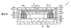
FIG. 1 is an exploded perspective view showing a touch pad according to an embodiment. FIG. 2A is a perspective view showing the touch pad according to the embodiment, and FIG. 2B is a schematic cross-sectional view of a cross section cut along the line II (b) -II (b) of FIG. 2A as viewed from the direction of an arrow. 2C is an example of a block diagram of the touch pad. 3A to 3C are cross-sectional views for explaining the operation of the limiter mechanism portion of the touch pad according to the embodiment.
本実施の形態に係る各図において、図形間の比率は、実際の比率とは異なる場合がある。また図2Bに示す矢印は、操作指9によって操作面7aになされた操作に伴って下向きに作用する荷重Fを示している。また図2Cでは、主な信号や情報の流れを矢印で示している。また図3A〜図3Cに示す上向きの矢印は、スプリング44の弾性力を示している。そして下向きの矢印は、操作面7aを押し下げる方向(荷重の付加方向)に作用する荷重を示している。さらに数値範囲を示す「A〜B」は、A以上B以下の意味で用いるものとする。In each figure according to the present embodiment, the ratio between the figures may differ from the actual ratio. Further, the arrow shown in FIG. 2B indicates a load F acting downward with the operation performed on the
操作検出装置としてのタッチパッド1は、一例として、車両の運転席と助手席の間のフロアコンソールに配置されている。このタッチパッド1は、一例として、図1の紙面左側が車両の後方側であり、右側が前方側に位置するように配置される。そしてタッチパッド1は、一例として、車両に搭載された電子機器を操作するように構成されている。このタッチパッド1は、例えば、操作面7aになされたなぞり操作、タップ操作、ピンチ操作及びプッシュ操作などを検出するように構成されている。As an example, the touch pad 1 as an operation detection device is arranged on the floor console between the driver's seat and the passenger seat of the vehicle. As an example, the touch pad 1 is arranged so that the left side of the paper surface of FIG. 1 is the rear side of the vehicle and the right side is the front side. The touch pad 1 is configured to operate an electronic device mounted on a vehicle as an example. The touch pad 1 is configured to detect, for example, a tracing operation, a tap operation, a pinch operation, a push operation, etc. performed on the
タッチパッド1は、例えば、図1〜図2Cに示すように、操作がなされる操作面7aを有する操作部7と、操作部7の下面7bに配置され、操作面7aに付加された荷重を検出する荷重センサ6と、荷重センサ6に対する予め定められた第1の荷重以下の荷重の付加を許容すると共に、荷重センサ6に対する予め定められた第1の荷重より大きい荷重の付加を操作部7の下面7bの接触によって制限して荷重センサ6を保護する保護部としてのリミッタ機構部4と、を有する。As shown in FIGS. 1 to 2C, the touch pad 1 is arranged on an
またタッチパッド1は、例えば、図2B及び図2Cに示すように、アクチュエータ8と、タッチセンサ70、発光素子71、荷重センサ6及びアクチュエータ8を制御する制御部100と、を備えている。Further, the touch pad 1 includes, for example, an
このタッチパッド1は、一例として、図1に示すように、操作面7aの四隅の下方に、荷重センサ6がそれぞれ配置されている。なお荷重センサ6の数は、これに限定されない。As an example, in this touch pad 1, as shown in FIG. 1,
リミッタ機構部4と操作部7は、例えば、図1及び図2Aに示すように、筐体2に取り付けられている。この筐体2は、一例として、PBT(ポリブチレンテレフタレート)などの樹脂材料を用いて形成されている。この筐体2と後述するベース40との間には、例えば、図1及び図2Aに示すように、樹脂材料によって形成された4つのクッション3が配置されている。このクッション3は、筐体2の嵌込部20に取り付けられている。The
(リミッタ機構部4の構成)
リミッタ機構部4は、例えば、図3A〜図3Cに示すように、荷重センサ6と接触するプレート46と、プレート46に対して操作部7の方向に弾性力を付加する弾性体としてのスプリング44と、プレート46とスプリング44とを収容する収容部400、及び収容部400と繋がって荷重センサ6の一部が侵入する開口401を有するベース40と、開口401の反対側の収容部400の端部を塞ぐようにベース40に取り付けられたキャップ42と、を有する。(Structure of limiter mechanism part 4)
As shown in FIGS. 3A to 3C, the
このキャップ42、スプリング44及びプレート46は、荷重センサ6の数に応じて4つのセットがベース40に取り付けられる。従ってベース40には、荷重センサ6の設置位置に応じて4つの収容部400及び開口401が設けられている。この収容部400は、例えば、矩形状を有するプレート46が移動可能な形状となっている。Four sets of the
ベース40は、一例として、ABS(アクリロニトリル・ブタジエン・スチレン)などの樹脂材料を用いて形成されている。このベース40の上面40a側には、操作部7が配置される。The
またベース40には、例えば、図3A〜図3Cに示すように、収容部400を挟むように凹部405が形成されている。この凹部405には、爪406が形成されている。Further, in the
筐体2とベース40との間には、例えば、図2Bに示すように、下面40bに接触するようにアクチュエータ8が配置されている。An
キャップ42は、例えば、PC(ポリカーボネート)などの樹脂材料を用いて形成されている。このキャップ42は、例えば、細長い板を両端が向かい合うように直角に折り曲げたような形状を有している。従ってキャップ42は、例えば、図1に示すように、底部42aと、底部42aの両端に位置して対向する側部42cと、を有している。The
底部42aには、凸形状を有する支持部42bが設けられている。この支持部42bには、スプリング44の一方端部が挿入される。The
側部42cには、開口42dが設けられている。この開口42dは、例えば、図3A〜図3Cに示すように、ベース40の凹部405の爪406が嵌り込むように構成されている。つまりキャップ42は、凹部405に側部42cが挿入され、爪406が開口42dに嵌り込むことによってベース40と一体となる。The
スプリング44は、一例として、炭素鋼(ピアノ線)を用いたコイルばねである。なお弾性体としては、コイルばねに限定されず、プレート46に必要な弾性力を付加すると共に元の形状に復帰するものであれば良い。The
プレート46は、一例として、POM(ポリアセタール)などの樹脂材料を用いて板状に形成されている。このプレート46の表面46aは、例えば、図3A〜図3Cに示すように、荷重センサ6と接触すると共に、収容部400の上内面400aと接触している。そして裏面46bには、凸形状を有する支持部46cが設けられている。この支持部46cには、スプリング44の他方端部が挿入される。従ってスプリング44は、キャップ42とプレート46によって支持されている。As an example, the
ここでスプリング44は、ベース40に収容された状態において、上述の予め定められた第1の荷重(一例として、10N)より小さい第2の荷重(一例として、8N)以上、予め定められた第1の荷重以下の荷重範囲で弾性変形を行うように構成されている。つまりスプリング44は、ベース40に収容された状態において、プレート46に対して第2の荷重に等しい弾性力(一例として、8N)を付加している。Here, in the state of being housed in the
またリミッタ機構部4は、この荷重範囲内の荷重の付加では、プレート46を介してスプリング44が弾性変形して荷重センサ6の移動を許容し、荷重センサ6によるゼロから予め定められた第1の荷重までの荷重の検出を可能とし、予め定められた第1の荷重より大きい荷重の付加では、ベース40の上面40aが操作部7の下面7bと接触して荷重センサ6の移動を規制し、荷重センサ6による予め定められた第1の荷重より大きい荷重の検出を制限するように構成されている。Further, in the
スプリング44は、キャップ42がベース40に取り付けられると、圧縮した状態で収容部400に収納される。この圧縮した状態のスプリング44は、例えば、図3Aに示すように、プレート46に対して弾性力F1を付加する。この弾性力F1は、一例として、予め定められた第1の荷重が10Nの場合、8Nである。When the
ここで荷重Fが操作面7aの中央に付加され、また荷重センサ6が操作面7aの四隅に配置されている場合、それぞれの荷重センサ6には、理想的にはF/4の荷重が付加される。以下では、図3A〜図3Cに図示された荷重センサ6の直上に荷重Fが付加され、当該荷重Fがこの荷重センサ6及びリミッタ機構部4に作用する場合について説明する。Here, when the load F is applied to the center of the
図3Aに示すように、例えば、操作面7aに対してスプリング44の弾性力F1以下の荷重Fが付加された場合、プレート46は、ベース40に固定されているように動かない。この際、荷重センサ6は、荷重Fを検出する。As shown in FIG. 3A, for example, when a load F equal to or less than the elastic force F1 of the
図3Bに示すように、例えば、操作面7aに対してスプリング44の弾性力F1より大きい荷重Fが付加された場合、スプリング44は、操作面7a、荷重センサ6及びプレート46を介して荷重Fを受けて圧縮される。この際、荷重センサ6は、荷重Fを検出する。なお図3Bに示すスプリング44の弾性力F2は、例えば、圧縮されている分、弾性力F1よりも大きくなる。そして操作面7aは、荷重Fと弾性力F2の釣り合いの位置まで筐体2に向かって移動する。As shown in FIG. 3B, for example, when a load F larger than the elastic force F1 of the
図3Cに示すように、さらに荷重Fが大きくなると、操作面7aが荷重Fの付加方向に移動して操作部7の下面7bとベース40の上面40aが接触してプレート46の移動が規制されるので、スプリング44の弾性力F3が最大値となる。そしてこの弾性力F3を生じさせる荷重、つまり操作部7の下面7bとベース40の上面40aが接触する際の荷重が予め定められた第1の荷重である。As shown in FIG. 3C, when the load F becomes larger, the
図3Cに示す荷重センサ6は、この弾性力F3を生じさせる荷重を検出する。また当該荷重よりも大きい荷重が操作面7aに付加された場合、スプリング44の弾性力F3を生じさせる荷重以外の荷重は、ベース40によって受けることになるので、荷重センサ6には、弾性力F3を生じさせる荷重のみを検出する。なおスプリング44の弾性力F3の最大値は、一例として、予め定められた第1の荷重が10Nの場合、10Nである。The
例えば、荷重Fが600Nであった場合、荷重センサ6には、予め定められた第1の荷重として10Nのみが付加され、ベース40が残りの荷重(590N)を受けるので、想定外の過荷重が荷重センサ6に付加されることを避けることができる。For example, when the load F is 600N, only 10N is added to the
本実施の形態のリミッタ機構部4は、一例として、1つの荷重センサ6に対して0〜10Nまでの荷重が作用するように規制している。つまり1つの荷重センサ6の検出範囲は、一例として、0〜10Nである。As an example, the
(荷重センサ6の構成)
荷重センサ6は、例えば、ピエゾ抵抗方式や静電容量方式のMEMS(Micro Electro Mechanical Systems)である。本実施の形態の荷重センサ6は、一例といて、静電容量方式のセンサであり、4つのゲージによってブリッジ回路が組まれている。(Structure of load sensor 6)
The
この荷重センサ6は、例えば、本体60からロードボタン61が突出している。荷重センサ6は、ロードボタン61に荷重が付加されることにより、内部のゲージの抵抗値が変わってブリッジ回路の出力が変化するように構成されている。In this
4つの荷重センサ6は、例えば、図2Cに示すように、荷重信号S2〜荷重信号S5を制御部100に出力する。制御部100は、例えば、この荷重信号S2〜荷重信号S5を荷重に変換し、プッシュ操作の有無を判定する。Four
(操作部7の構成)
操作部7は、一例として、図1に示すように、タッチセンサ70と、ライトガイド72と、パネル74と、を有する。(Structure of operation unit 7)
As an example, the
タッチセンサ70は、例えば、静電容量方式のタッチセンサであり、マルチタッチを検出するように構成されている。具体的にはタッチセンサ70は、複数の駆動電極及び検出電極が絶縁性を保ちながら交差して基板上に設けられている。The
この基板は、一例として、図1に示すように、プリント配線基板であり、対向する端部に複数の発光素子71が配置されている。この発光素子71は、例えば、制御部100から出力される照明信号S7に基づいて発光する。As an example, this substrate is a printed wiring board as shown in FIG. 1, and a plurality of
タッチセンサ70は、複数の駆動電極と複数の検出電極の全ての組み合わせの静電容量を読み出し、1周期分の静電容量を静電容量S1として制御部100に出力する。The
ライトガイド72は、例えば、アクリルなどの透明度が高い樹脂材料を用いてシート状に形成されている。このライトガイド72は、例えば、接着剤によってパネル74に取り付けられている。The
またライトガイド72は、上述の発光素子71の光を操作面7a方向に案内して操作面7aを照明する。よってライトガイド72には、発光素子71の光を拡散する拡散粒子などが含まれていても良い。Further, the
パネル74は、例えば、PCなどの透明な樹脂材料を用いて形成されている。そしてパネル74は、例えば、光が透過する透光領域と、光を遮光する遮光領域と、を印刷などによって形成することによって操作面7aに意匠が形成されている。The
このパネル74は、例えば、図2Aに示すように、上部が操作面7aとなり、下部が解放された箱形状を有している。またパネル74は、ライトガイド72及びタッチセンサ70と一体となっている。As shown in FIG. 2A, for example, the
(アクチュエータ8の構成)
アクチュエータ8は、ベース40を介して操作面7aを振動させるものである。このアクチュエータ8は、一例として、ユニモルフ型の圧電アクチュエータである。(Structure of actuator 8)
The
アクチュエータ8は、例えば、図2Cに示すように、制御部100から出力される駆動信号S6に基づいて振動する。
(制御部100の構成)
制御部100は、例えば、記憶されたプログラムに従って、取得したデータに演算、加工などを行うCPU(Central Processing Unit)、半導体メモリであるRAM(Random Access Memory)及びROM(Read Only Memory)などから構成されるマイクロコンピュータである。このROMには、例えば、制御部100が動作するためのプログラムと、静電しきい値101と、荷重しきい値102と、駆動情報103と、が格納されている。RAMは、例えば、一時的に演算結果などを格納する記憶領域として用いられる。(Structure of Control Unit 100)
The
制御部100は、例えば、操作部7が操作を検出すると共に荷重センサ6が当該操作に伴う荷重を検出した場合、プッシュ操作がなされたとして被制御装置を制御すると共にアクチュエータ8を制御して操作面7aを振動させ、プッシュ操作を受け付けたことを示す触覚フィードバックを呈示するように構成されている。そして制御部100は、操作が検出された点の座標値、プッシュ操作の有無などの情報を含む操作情報S8を生成して被制御装置に出力する。For example, when the
この被制御装置とは、例えば、ナビゲーション装置、音楽及び映像再生装置、空調装置などである。The controlled device is, for example, a navigation device, a music and video reproduction device, an air conditioner, and the like.
具体的には、制御部100は、タッチセンサ70から周期的に静電容量S1を取得して静電しきい値101と比較する。制御部100は、例えば、静電しきい値101以上の静電容量が存在した場合、当該静電容量の分布に基づいて操作がなされた操作面7a上の検出点を算出する。この算出は、一例として、加重平均などによって行われる。Specifically, the
また制御部100は、荷重センサ6からの荷重信号S2〜荷重信号S5に基づく荷重と荷重しきい値102とを比較する。制御部100は、荷重しきい値102以上の荷重が検出された場合、プッシュ操作がなされたと判定する。The
駆動情報103は、例えば、駆動信号S6の駆動パターンに関する情報である。制御部100は、プッシュ操作が検出された場合、プッシュ操作を受け付けたことを示す駆動パターンを有する駆動信号S6を生成してアクチュエータ8に出力して触覚フィードバックを呈示する。なお変形例として、触覚フィードバックは、例えば、機械式の押しボタンの触覚を模した触覚フィードバックなどであっても良い。Drive
また変形例として制御部100は、なぞり操作やタッチ操作などにおいて、静電しきい値101以上の静電容量の検出と、予め定められた第1の荷重以上の荷重の検出と、を組み合わせて操作の判定を行うように構成されても良い。制御部100は、この組み合わせの判定により、操作面7aから離れて、つまりフローティング状態にある操作指などの誤検出を抑制することができる。また制御部100は、この組み合わせの判定により、車両の振動に伴って意図せず操作指が触れて検出された荷重に基づく誤検出を抑制することができる。Further, as a modification, the
以下にタッチパッド1の動作について説明する。The operation of the touch pad 1 will be described below.
(動作)
タッチパッド1の制御部100は、例えば、車両の電源が投入されると、照明信号S7を発光素子71に出力して操作面7aを照明する。そして制御部100は、静電容量S1、荷重信号S2〜荷重信号S5を取得し、静電しきい値101及び荷重しきい値102と比較しながら監視する。(motion)
For example, when the power of the vehicle is turned on, the
制御部100は、操作が検出され、プッシュ操作が検出されない場合、操作が検出された点の座標値とプッシュ操作がなされなかったことを含む操作情報S8を生成して被制御装置に出力する。また制御部100は、プッシュ操作が検出された場合、操作が検出された点の座標値とプッシュ操作がなされたことを含む操作情報S8を生成して被制御装置に出力する。
(実施の形態の効果)
本実施の形態に係るタッチパッド1は、過荷重から荷重センサ6を保護することができる。具体的には、タッチパッド1は、荷重センサ6が破壊されるほどの大きい荷重(過荷重)が操作面7aに付加された場合、操作部7が荷重の付加方向に移動してベース40と接触することで予め定められた第1の荷重以上の荷重が荷重センサ6に付加されることを規制する。従ってタッチパッド1は、この構成を採用しない場合と比べて、過荷重が荷重センサ6に付加されることがないので、過荷重から荷重センサ6を保護することができる。(Effect of embodiment)
The touch pad 1 according to the present embodiment can protect the
タッチパッド1は、スプリング44のばね定数を変更することによって容易に荷重センサ6に付加される最大荷重を調整することができるので、荷重センサ6の耐荷重性能に応じた保護ができる。またタッチパッド1は、最大荷重を容易に調整することができるので、荷重センサ6の耐荷重性能が変わっても設計変更する必要がなく、様々な仕様に対応することが可能となって製造コストが抑制される。そしてタッチパッド1は、荷重センサ6の耐荷重性能に応じた保護ができるので、荷重センサ6の直上に過荷重が付加されても荷重センサ6を保護することができる。Since the touch pad 1 can easily adjust the maximum load applied to the
なお変形例としてタッチパッド1は、タッチセンサ70を備えない構成としても良い。このタッチパッド1は、操作部7と4つの荷重センサ6とが確実に接触しているので、各荷重センサ6の出力に応じて操作がなされた位置を精度良く検出することが可能である。As a modification, the touch pad 1 may be configured not to include the
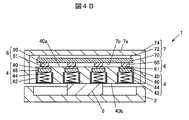
ここで図4Aは、他の実施の形態に係る操作検出装置を示す説明図であり、図4Bは、図4AのIV(b)-IV(b)線で切断した断面を矢印方向から見た断面図である。以下に示す他の実施の形態において、上述の実施の形態と同じ機能及び構成を有する部分は、実施の形態と同じ符号を付し、その説明は省略するものとする。Here, FIG. 4A is an explanatory view showing an operation detection device according to another embodiment, and FIG. 4B is a cross section cut along the IV (b) -IV (b) line of FIG. 4A as viewed from the direction of an arrow. It is a cross-sectional view. In the other embodiments shown below, parts having the same functions and configurations as those in the above-described embodiment are designated by the same reference numerals as those in the embodiments, and the description thereof will be omitted.
この操作検出装置1aは、例えば、図4Aに示すように、空調装置の操作部として構成されている。この操作検出装置1aは、パネル74の表面に複数の操作ボタン740が配置されている。そして複数の操作ボタン740の下方には、例えば、図4Bに示すように、上述のリミッタ機構部4と荷重センサ6が対となって配置されている。As shown in FIG. 4A, for example, the operation detection device 1a is configured as an operation unit of the air conditioner. In this operation detection device 1a, a plurality of operation buttons 740 are arranged on the surface of the
操作検出装置1aは、静電容量方式のタッチセンサ70によって操作がなされた操作ボタン740を検出すると共に、荷重センサ6によって当該操作ボタン740に対するプッシュ操作を検出するように構成されている。操作検出装置1aは、プッシュ操作がなされた操作ボタン740に関する操作情報S8を空調装置に出力する。空調装置は、操作情報S8に基づいてプッシュ操作がなされた操作ボタン740に割り当てられた機能を実行する。The operation detection device 1a is configured to detect the operation button 740 operated by the
この操作検出装置1aは、リミッタ機構部4を備えることにより、過荷重が荷重センサ6に付加されることがないので荷重センサ6を保護することができる。なお変形例として操作検出装置1aは、リミッタ機構部4と荷重センサ6の対が操作面7aの四隅の下方にのみに配置されても良い。Since the operation detection device 1a includes the
以上、本発明のいくつかの実施の形態及び変形例を説明したが、これらの実施の形態及び変形例は、一例に過ぎず、請求の範囲に係る発明を限定するものではない。これら新規な実施の形態及び変形例は、その他の様々な形態で実施されることが可能であり、本発明の要旨を逸脱しない範囲で、種々の省略、置き換え、変更などを行うことができる。また、これら実施の形態及び変形例の中で説明した特徴の組合せの全てが発明の課題を解決するための手段に必須であるとは限らない。さらに、これら実施の形態及び変形例は、発明の範囲及び要旨に含まれると共に、請求の範囲に記載された発明とその均等の範囲に含まれる。Although some embodiments and modifications of the present invention have been described above, these embodiments and modifications are merely examples and do not limit the invention according to the claims. These novel embodiments and modifications can be implemented in various other embodiments, and various omissions, replacements, changes, etc. can be made without departing from the gist of the present invention. Moreover, not all combinations of features described in these embodiments and modifications are essential as means for solving the problems of the invention. Further, these embodiments and modifications are included in the scope and gist of the invention, and are included in the invention described in the claims and the equivalent scope thereof.
1 タッチパッド
1a 操作検出装置
2 筐体
4 リミッタ機構部
6 荷重センサ
7 操作部
7a 操作面
7b 下面
40 ベース
40a 上面
40b 下面
42 キャップ
44 スプリング
46 プレート
100 制御部
102 荷重しきい値
103 駆動情報
400 収容部
401 開口
740 操作ボタン
1 Touch pad 1a
Claims (10)
Translated fromJapanese前記操作部の下面に一方側が接触して配置され、前記操作面に付加された荷重を検出する荷重センサと、
前記荷重センサに対する予め定められた第1の荷重以下の荷重の付加を許容すると共に、前記荷重センサに対する前記予め定められた第1の荷重より大きい荷重の付加を前記操作部の前記下面と自身の上面の接触によって制限して前記荷重センサを保護する保護部と、
を備え、
前記保護部は、前記荷重センサの他方側と表面が接触するプレートと、前記プレートの裏面に配置され、前記プレートに対して前記操作部の方向に弾性力を付加すると共に前記操作部に付加された荷重により弾性変形する弾性体と、前記プレートと前記弾性体とを収容し、上内面が前記弾性体の弾性力により前記プレートの前記表面と接触する収容部、及び前記収容部と繋がって前記荷重センサの一部が侵入し、前記上面と前記上内面に貫通する開口を有するベースと、を有する、
操作検出装置。An operation unit that has an operation surface on which operations are performed,
A load sensor, which is arranged so that one side is in contact with the lower surface of the operation unit and detects a load applied to the operation surface,
A load equal to or less than a predetermined first load is allowed to be applied to the load sensor, and a load larger than the predetermined first load is applied to the load sensor on the lower surface of the operation unitand itself. A protective unit that protects the load sensor by limiting it by contact with theupper surface,
Equipped witha,
The protective portion is arranged on the back surface of the plate and the plate in which the other side of the load sensor is in contact with the front surface, and an elastic force is applied to the plate in the direction of the operation portion and is added to the operation portion. An elastic body that elastically deforms due to a heavy load, a housing portion that accommodates the plate and the elastic body, and an upper inner surface that comes into contact with the surface of the plate due to the elastic force of the elastic body, and a housing portion that is connected to the housing portion. It has a base having an opening through which a part of the load sensor enters and penetrates the upper surface and the upper inner surface.
Operation detector.
請求項2に記載の操作検出装置。In a state of being accommodated in the accommodating portion, the elastic body undergoes elastic deformation in a load range equal to or greater than a second load smaller than the predetermined first load and equal to or less than the predetermined first load. ,
The operation detection device according to claim 2.
請求項3に記載の操作検出装置。When a load is applied within the load range, the protective portion elastically deforms the elastic body through the plate to allow the load sensor to move, and the load sensor allows the load sensor to move from zero to the predetermined first. When a load larger than the predetermined first load is applied, the upper surface of the base comes into contact with the lower surface of the operation unit to restrict the movement of the load sensor. , Limiting the detection of a load greater than the predetermined first load by the load sensor.
The operation detection device according to claim 3.
請求項3又は4に記載の操作検出装置。When a load larger than the predetermined first load is applied to the protective portion, the contact between the upper surface of the base and the lower surface of the operation portion causes the protective portion to have a load other than the predetermined first load. It has a configuration in which the base receives a load.
The operation detection device according to claim 3 or 4.
請求項1乃至5のいずれか1項に記載の操作検出装置。The load sensor has a main body having a bridge circuit built by a gauge inside and a load button protruding from the main body, and the resistance value of the gauge changes according to the load applied to the load button. It has a configuration in which the output of the bridge circuit changes.
The operation detection device according to any one of claims 1 to 5.
請求項1乃至6のいずれか1項に記載の操作検出装置。The load based on the load signal from the load sensor is compared with the load threshold value, and when a load equal to or higher than the load threshold value is detected, it is determined that the push operation of the operation unit has been performed, and the operation information is received. Equipped with a control unit that outputs to the control device,
The operation detection device according to any one of claims 1 to 6.
前記保護部は、前記複数の荷重センサに応じた複数の保護部を含む、
請求項1乃至7のいずれか1項に記載の操作検出装置。The load sensor includes a plurality of load sensors.
The protection unit includes a plurality of protection units corresponding to the plurality of load sensors.
The operation detection device according to any one of claims 1 to 7.
請求項8に記載の操作検出装置。The plurality of load sensors are provided below the four corners of the operation surface, respectively.
The operation detection device according to claim 8.
前記複数の荷重センサは、前記複数の操作ボタンの下方にそれぞれ設けられている、
請求項8に記載の操作検出装置。The operation unit is configured by arranging a plurality of operation buttons on the operation surface.
The plurality of load sensors are provided below the plurality of operation buttons, respectively.
The operation detection device according to claim 8.
Applications Claiming Priority (3)
| Application Number | Priority Date | Filing Date | Title |
|---|---|---|---|
| JP2017150698 | 2017-08-03 | ||
| JP2017150698 | 2017-08-03 | ||
| PCT/JP2018/024909WO2019026504A1 (en) | 2017-08-03 | 2018-06-29 | Operation detection device |
Publications (2)
| Publication Number | Publication Date |
|---|---|
| JPWO2019026504A1 JPWO2019026504A1 (en) | 2020-04-23 |
| JP6837555B2true JP6837555B2 (en) | 2021-03-03 |
Family
ID=65232556
Family Applications (1)
| Application Number | Title | Priority Date | Filing Date |
|---|---|---|---|
| JP2019533983AActiveJP6837555B2 (en) | 2017-08-03 | 2018-06-29 | Operation detector |
Country Status (5)
| Country | Link |
|---|---|
| US (1) | US11194412B2 (en) |
| JP (1) | JP6837555B2 (en) |
| CN (1) | CN110998498A (en) |
| DE (1) | DE112018003952T5 (en) |
| WO (1) | WO2019026504A1 (en) |
Families Citing this family (3)
| Publication number | Priority date | Publication date | Assignee | Title |
|---|---|---|---|---|
| CN110550579B (en)* | 2019-09-10 | 2021-05-04 | 灵动科技(北京)有限公司 | Automatic guide forklift |
| JP7235003B2 (en)* | 2020-05-19 | 2023-03-08 | 株式会社デンソー | Vehicle operating device |
| CN111590435B (en)* | 2020-05-27 | 2021-07-06 | 聊城开发区隆阳机械制造有限责任公司 | Realize polishing sweeps collection device to hardware based on gravity changes |
Family Cites Families (27)
| Publication number | Priority date | Publication date | Assignee | Title |
|---|---|---|---|---|
| US5263375A (en)* | 1987-09-18 | 1993-11-23 | Wacoh Corporation | Contact detector using resistance elements and its application |
| US5510812A (en)* | 1994-04-22 | 1996-04-23 | Hasbro, Inc. | Piezoresistive input device |
| US6016097A (en)* | 1997-08-29 | 2000-01-18 | Eaton Corporation | Motion transducer |
| JP2001264189A (en)* | 2000-03-16 | 2001-09-26 | Kubota Corp | Load cell |
| KR100499143B1 (en)* | 2003-02-27 | 2005-07-04 | 삼성전자주식회사 | Ground reaction force detection module for walking robot and robot foot structure adopting the same |
| US7343223B2 (en)* | 2003-03-13 | 2008-03-11 | Alps Electric Co., Ltd. | Robot apparatus and load sensor |
| US20060181517A1 (en)* | 2005-02-11 | 2006-08-17 | Apple Computer, Inc. | Display actuator |
| CN101681216B (en)* | 2007-05-31 | 2012-10-03 | 日本写真印刷株式会社 | Insert molding laminate and its manufacturing method, and, insert molding and its manufacturing method |
| EP2416231A4 (en)* | 2009-03-31 | 2013-09-04 | Nissha Printing | Information input device and pressure detection unit used for information input device |
| JP2011191103A (en)* | 2010-03-12 | 2011-09-29 | Alps Electric Co Ltd | Force sensor and method of manufacturing the same |
| JP5688792B2 (en)* | 2010-09-10 | 2015-03-25 | 国立大学法人弘前大学 | Sensor device and distribution measuring device |
| JP5327173B2 (en) | 2010-09-22 | 2013-10-30 | 株式会社デンソー | Touch position detection circuit for touch panel display |
| GB2488600B (en)* | 2011-03-04 | 2013-05-29 | Hm Technology Internat Ltd | A force sensor |
| JP5666698B2 (en) | 2011-05-20 | 2015-02-12 | アルプス電気株式会社 | LOAD DETECTING DEVICE, ELECTRONIC DEVICE USING THE LOAD DETECTING DEVICE, AND METHOD FOR MANUFACTURING LOAD DETECTING DEVICE |
| JP2013016336A (en)* | 2011-07-04 | 2013-01-24 | Tokai Rika Co Ltd | Switch device |
| GB201111340D0 (en)* | 2011-07-04 | 2011-08-17 | Meso Ltd | Load measuring system |
| JP2013217679A (en)* | 2012-04-05 | 2013-10-24 | Alps Electric Co Ltd | Load detection device, input device using the same and method for manufacturing the input device |
| US9164003B2 (en)* | 2012-10-11 | 2015-10-20 | Honeywell International Inc. | Force sensor with mechanical over-force transfer mechanism |
| WO2015065639A1 (en)* | 2013-10-30 | 2015-05-07 | Honeywell International Inc. | Force sensor with gap-controlled over-force protection |
| JP5587491B1 (en)* | 2013-12-27 | 2014-09-10 | 株式会社フジクラ | Electronic device and control method of electronic device |
| JP6188231B2 (en)* | 2014-02-26 | 2017-08-30 | アルプス電気株式会社 | LOAD DETECTING DEVICE AND ELECTRONIC DEVICE USING THE LOAD DETECTING DEVICE |
| EP3177978A4 (en)* | 2014-08-04 | 2018-03-21 | Nextinput, Inc. | Force sensitive touch panel devices |
| US10096239B2 (en)* | 2014-12-31 | 2018-10-09 | Pelco Products, Inc. | Accessible pedestrian pushbutton station |
| JP6086272B1 (en) | 2016-02-23 | 2017-03-01 | 大陽日酸株式会社 | Nitrogen and oxygen production method, and nitrogen and oxygen production apparatus |
| US10126183B2 (en)* | 2016-04-14 | 2018-11-13 | Nextinput, Inc. | Actuator for force sensor and method of assembling a force-sensing system |
| US10416803B2 (en)* | 2016-09-21 | 2019-09-17 | Apple Inc. | Gasket with embedded capacitive sensor |
| FR3066451B1 (en)* | 2017-05-18 | 2019-05-03 | Aptiv Technologies Limited | CONTROL PANEL FOR MOTOR VEHICLE |
- 2018
- 2018-06-29JPJP2019533983Apatent/JP6837555B2/enactiveActive
- 2018-06-29CNCN201880050409.0Apatent/CN110998498A/enactivePending
- 2018-06-29USUS16/623,957patent/US11194412B2/enactiveActive
- 2018-06-29WOPCT/JP2018/024909patent/WO2019026504A1/ennot_activeCeased
- 2018-06-29DEDE112018003952.8Tpatent/DE112018003952T5/ennot_activeCeased
Also Published As
| Publication number | Publication date |
|---|---|
| CN110998498A (en) | 2020-04-10 |
| US11194412B2 (en) | 2021-12-07 |
| US20200142512A1 (en) | 2020-05-07 |
| WO2019026504A1 (en) | 2019-02-07 |
| DE112018003952T5 (en) | 2020-05-07 |
| JPWO2019026504A1 (en) | 2020-04-23 |
Similar Documents
| Publication | Publication Date | Title |
|---|---|---|
| US10942571B2 (en) | Laptop computing device with discrete haptic regions | |
| JP6837555B2 (en) | Operation detector | |
| CN109656458B (en) | input device | |
| JP5038422B2 (en) | Control module for automobile | |
| US9141219B2 (en) | Operating device for providing tactile feedback on a depressible touch screen | |
| JP2016120890A (en) | Vehicular switching device | |
| US20180081437A1 (en) | Dynamically configurable input structure with tactile overlay | |
| KR102720074B1 (en) | Control devices for automobiles | |
| JP2013182424A (en) | Input device | |
| US20230347740A1 (en) | Display device and input device | |
| CN110998500A (en) | Operation detection device | |
| JP7669627B2 (en) | Input Devices | |
| WO2017010338A1 (en) | Operation apparatus | |
| US11863176B2 (en) | Operation panel | |
| CN112540692B (en) | Touch control operation device | |
| CN114879864B (en) | Touch control device | |
| CN110506250B (en) | Touch-sensitive control device for a motor vehicle and method for operating a touch-sensitive control device | |
| US11463089B1 (en) | Haptic reactive electrical switch | |
| JP2022097801A (en) | On-vehicle display device | |
| JP2019152944A (en) | Operation input device | |
| US20250269793A1 (en) | Shift device | |
| KR102482926B1 (en) | Automotive switch with damping function | |
| WO2016006216A1 (en) | Switch and input device using same | |
| JP6919620B2 (en) | Electronics | |
| JP2025128672A (en) | display device |
Legal Events
| Date | Code | Title | Description |
|---|---|---|---|
| A621 | Written request for application examination | Free format text:JAPANESE INTERMEDIATE CODE: A621 Effective date:20191210 | |
| A131 | Notification of reasons for refusal | Free format text:JAPANESE INTERMEDIATE CODE: A131 Effective date:20201201 | |
| A521 | Request for written amendment filed | Free format text:JAPANESE INTERMEDIATE CODE: A523 Effective date:20210112 | |
| TRDD | Decision of grant or rejection written | ||
| A01 | Written decision to grant a patent or to grant a registration (utility model) | Free format text:JAPANESE INTERMEDIATE CODE: A01 Effective date:20210202 | |
| A61 | First payment of annual fees (during grant procedure) | Free format text:JAPANESE INTERMEDIATE CODE: A61 Effective date:20210209 | |
| R150 | Certificate of patent or registration of utility model | Ref document number:6837555 Country of ref document:JP Free format text:JAPANESE INTERMEDIATE CODE: R150 |