JP6837362B2 - Automatic analyzer - Google Patents
Automatic analyzerDownload PDFInfo
- Publication number
- JP6837362B2 JP6837362B2JP2017052059AJP2017052059AJP6837362B2JP 6837362 B2JP6837362 B2JP 6837362B2JP 2017052059 AJP2017052059 AJP 2017052059AJP 2017052059 AJP2017052059 AJP 2017052059AJP 6837362 B2JP6837362 B2JP 6837362B2
- Authority
- JP
- Japan
- Prior art keywords
- reagent container
- reagent
- reagent bottle
- loading
- operation handle
- Prior art date
- Legal status (The legal status is an assumption and is not a legal conclusion. Google has not performed a legal analysis and makes no representation as to the accuracy of the status listed.)
- Active
Links
Images


Classifications
- G—PHYSICS
- G01—MEASURING; TESTING
- G01N—INVESTIGATING OR ANALYSING MATERIALS BY DETERMINING THEIR CHEMICAL OR PHYSICAL PROPERTIES
- G01N35/00—Automatic analysis not limited to methods or materials provided for in any single one of groups G01N1/00 - G01N33/00; Handling materials therefor
- G01N35/02—Automatic analysis not limited to methods or materials provided for in any single one of groups G01N1/00 - G01N33/00; Handling materials therefor using a plurality of sample containers moved by a conveyor system past one or more treatment or analysis stations
- G01N35/025—Automatic analysis not limited to methods or materials provided for in any single one of groups G01N1/00 - G01N33/00; Handling materials therefor using a plurality of sample containers moved by a conveyor system past one or more treatment or analysis stations having a carousel or turntable for reaction cells or cuvettes
- G—PHYSICS
- G01—MEASURING; TESTING
- G01N—INVESTIGATING OR ANALYSING MATERIALS BY DETERMINING THEIR CHEMICAL OR PHYSICAL PROPERTIES
- G01N35/00—Automatic analysis not limited to methods or materials provided for in any single one of groups G01N1/00 - G01N33/00; Handling materials therefor
- G01N35/0099—Automatic analysis not limited to methods or materials provided for in any single one of groups G01N1/00 - G01N33/00; Handling materials therefor comprising robots or similar manipulators
- G—PHYSICS
- G01—MEASURING; TESTING
- G01N—INVESTIGATING OR ANALYSING MATERIALS BY DETERMINING THEIR CHEMICAL OR PHYSICAL PROPERTIES
- G01N35/00—Automatic analysis not limited to methods or materials provided for in any single one of groups G01N1/00 - G01N33/00; Handling materials therefor
- G01N35/02—Automatic analysis not limited to methods or materials provided for in any single one of groups G01N1/00 - G01N33/00; Handling materials therefor using a plurality of sample containers moved by a conveyor system past one or more treatment or analysis stations
- G01N35/04—Details of the conveyor system
- G—PHYSICS
- G01—MEASURING; TESTING
- G01N—INVESTIGATING OR ANALYSING MATERIALS BY DETERMINING THEIR CHEMICAL OR PHYSICAL PROPERTIES
- G01N35/00—Automatic analysis not limited to methods or materials provided for in any single one of groups G01N1/00 - G01N33/00; Handling materials therefor
- G01N35/10—Devices for transferring samples or any liquids to, in, or from, the analysis apparatus, e.g. suction devices, injection devices
- G01N35/1002—Reagent dispensers
- G—PHYSICS
- G01—MEASURING; TESTING
- G01N—INVESTIGATING OR ANALYSING MATERIALS BY DETERMINING THEIR CHEMICAL OR PHYSICAL PROPERTIES
- G01N35/00—Automatic analysis not limited to methods or materials provided for in any single one of groups G01N1/00 - G01N33/00; Handling materials therefor
- G01N35/02—Automatic analysis not limited to methods or materials provided for in any single one of groups G01N1/00 - G01N33/00; Handling materials therefor using a plurality of sample containers moved by a conveyor system past one or more treatment or analysis stations
- G01N35/04—Details of the conveyor system
- G01N2035/0401—Sample carriers, cuvettes or reaction vessels
- G01N2035/0406—Individual bottles or tubes
- G—PHYSICS
- G01—MEASURING; TESTING
- G01N—INVESTIGATING OR ANALYSING MATERIALS BY DETERMINING THEIR CHEMICAL OR PHYSICAL PROPERTIES
- G01N35/00—Automatic analysis not limited to methods or materials provided for in any single one of groups G01N1/00 - G01N33/00; Handling materials therefor
- G01N35/02—Automatic analysis not limited to methods or materials provided for in any single one of groups G01N1/00 - G01N33/00; Handling materials therefor using a plurality of sample containers moved by a conveyor system past one or more treatment or analysis stations
- G01N35/04—Details of the conveyor system
- G01N2035/0401—Sample carriers, cuvettes or reaction vessels
- G01N2035/0412—Block or rack elements with a single row of samples
- G—PHYSICS
- G01—MEASURING; TESTING
- G01N—INVESTIGATING OR ANALYSING MATERIALS BY DETERMINING THEIR CHEMICAL OR PHYSICAL PROPERTIES
- G01N35/00—Automatic analysis not limited to methods or materials provided for in any single one of groups G01N1/00 - G01N33/00; Handling materials therefor
- G01N35/02—Automatic analysis not limited to methods or materials provided for in any single one of groups G01N1/00 - G01N33/00; Handling materials therefor using a plurality of sample containers moved by a conveyor system past one or more treatment or analysis stations
- G01N35/04—Details of the conveyor system
- G01N2035/0439—Rotary sample carriers, i.e. carousels
- G01N2035/0443—Rotary sample carriers, i.e. carousels for reagents
Landscapes
- Chemical & Material Sciences (AREA)
- General Health & Medical Sciences (AREA)
- Life Sciences & Earth Sciences (AREA)
- Health & Medical Sciences (AREA)
- Analytical Chemistry (AREA)
- Biochemistry (AREA)
- Physics & Mathematics (AREA)
- General Physics & Mathematics (AREA)
- Immunology (AREA)
- Pathology (AREA)
- Chemical Kinetics & Catalysis (AREA)
- Engineering & Computer Science (AREA)
- Robotics (AREA)
- Automatic Analysis And Handling Materials Therefor (AREA)
Description
Translated fromJapanese発明は、血液や尿といった生物学的サンプルの定性的ないし定量的分析を行う自動分析装置に係る。 The invention relates to an automated analyzer that performs qualitative or quantitative analysis of biological samples such as blood and urine.
自動分析装置は、血液その他の生物学的サンプルを自動的に分析して結果を出力する装置であり、病院や医療検査施設では必須の装置となっている。これらの自動分析装置は、より多種多用の検査をより短時間で行うことが求められている。 An automatic analyzer is a device that automatically analyzes blood and other biological samples and outputs the results, and is an indispensable device in hospitals and medical testing facilities. These automatic analyzers are required to perform a wider variety of inspections in a shorter time.
自動分析装置は、装置内に装填された試薬が不足しそうになった場合、試薬不足の警告をオペレータに発して、充填された新しい試薬との交換を促す。オペレータは一旦自動分析装置を停止して試薬の交換作業を行うので、試薬の交換作業が簡単かつ確実で、短時間で交換可能な構成が望ましい。 The automated analyzer issues a reagent shortage warning to the operator to prompt the operator to replace it with a new filled reagent when the reagent loaded in the device is about to run out. Since the operator temporarily stops the automatic analyzer and performs the reagent replacement work, it is desirable that the reagent replacement work is simple and reliable, and that the reagent can be replaced in a short time.
特許文献1に記載された自動分析器(自動分析装置)は、「分析のために使用する試薬を収納し、この試薬を所望する位置まで輸送する試薬駆動ディスク(301)と、試薬を含む試薬コンテナ(110)を一時的にスタンバイさせる試薬スタンバイ位置および磁気粒子を攪拌するための磁気粒子攪拌位置を有する固定ディスク(303)とを含む。試薬スタンバイ位置の一部は、装填システム(304)によって構成されている。分析リクエストステータスに従い、試薬コンテナ移動ユニット(305)が、試薬を含む試薬コンテナ(110)を、試薬駆動ユニット(301)と固定ディスク(303)との間で移動させるようになっている。試薬を含む試薬コンテナ(110)を内部に取り付けできるように構成された装填システム(304)を固定ディスク(303)の一部に設けることによって、試薬固定ディスクの作動状態に係わらず、試薬コンテナ(60)のいずれかを変更できるようにすると共に、システムが低温貯蔵機能を有することが可能」であるよう構成されている。 The automatic analyzer (automatic analyzer) described in Patent Document 1 states that "a reagent-driven disk (301) that stores a reagent used for analysis and transports the reagent to a desired position, and a reagent containing the reagent. Includes a fixed disk (303) with a reagent standby position to temporarily put the container (110) on standby and a magnetic particle agitation position to agitate the magnetic particles. Part of the reagent standby position is provided by the loading system (304). The reagent container moving unit (305) now moves the reagent container (110) containing the reagent between the reagent driving unit (301) and the fixed disk (303) according to the analysis request status. By providing a loading system (304) configured to be able to mount the reagent container (110) containing the reagent inside as a part of the fixing disk (303), regardless of the operating state of the reagent fixing disk. It is configured so that any of the reagent containers (60) can be modified and the system can have a cold storage function. "
特許文献1に開示された構成では、試薬ディスク(111)に試薬を装填するために、試薬を含む試薬コンテナ(110)を、モータのような電動アクチュエータによって駆動される試薬コンテナ移動ユニット(305)によって、試薬駆動ユニット(301)と固定ディスク(303)との間で移動させるよう構成されており、またさらに、システム内に試薬コンテナ(110)をマウントできるようにする装填システム(304)は、試薬アクチュエータ(402)によって上下方向に駆動される構成である。 In the configuration disclosed in Patent Document 1, in order to load the reagent into the reagent disk (111), the reagent container (110) containing the reagent is driven by an electric actuator such as a motor, and the reagent container moving unit (305). The loading system (304) is configured to move between the reagent drive unit (301) and the fixed disk (303), and also allows the reagent container (110) to be mounted within the system. It is configured to be driven in the vertical direction by the reagent actuator (402).
すなわち、複数の電動アクチュエータを用いて試薬コンテナ(110)を試薬ディスク(111)に装填する構成であるため、構造の簡素化や小型化、あるいは動作制御アルゴリズムの簡素化には限界がある。 That is, since the reagent container (110) is loaded into the reagent disk (111) using a plurality of electric actuators, there is a limit to simplification and miniaturization of the structure or simplification of the operation control algorithm.
一方で、試薬コンテナを手で直接把持して装填する構成とした場合には、試薬コンテナを装填完了した際の位置ばらつきが生じやすい、という問題がある。 On the other hand, when the reagent container is directly grasped and loaded by hand, there is a problem that the position variation tends to occur when the reagent container is completely loaded.
本発明では、構造が簡単で小型化が可能であり、試薬の交換作業が簡単かつ確実で、短時間で試薬交換が可能な自動分析装置を提供することを目的とする。 An object of the present invention is to provide an automatic analyzer capable of simple structure, miniaturization, easy and reliable reagent exchange work, and quick reagent exchange.
上記目的を達成するために本発明は、例えば、開閉可能な開口を備え、内部の所定の位置に試薬容器を保持可能な試薬容器保持スロットを複数備えた試薬容器ホルダと、装填補助手段を設け、前記装填補助手段は、試薬容器を設置可能な試薬容器設置部と、前記試薬容器設置部を移動可能に支持する支柱と、前記試薬容器設置部をユーザによる操作に連動して操作する操作ハンドルとを設け、前記装填補助手段は、前記操作ハンドルのユーザ操作に連動して、前記試薬容器を上下方向に移動させて前記開口を介して前記試薬容器ホルダの外部から前記試薬容器ホルダの内部に搬入し、前記試薬容器を水平方向に移動させて前記試薬容器保持スロットに装填させるように補助し、前記操作ハンドルのユーザ操作に連動して、前記試薬容器を水平方向に移動させて前記試薬容器保持スロットから取り外し、前記試薬容器を上下方向に移動させて前記試薬容器保持スロットから前記開口を介して前記試薬容器ホルダの外部に搬出させるように補助する構成であり、前記試薬容器ホルダは、垂直軸のまわりに回転自在に配置された円筒状の中空のドラムと、前記ドラムの上面と下面と円筒状の側面とを覆った断熱カバーとをさらに備え、前記開口は上面の前記断熱カバーに設けられていることを特徴とする。
In order to achieve the above object, the present invention provides, for example, a reagent container holder having an opening / closing opening and a plurality of reagent container holding slots capable of holding a reagent container at a predetermined position inside, and a loading assisting means. The loading assisting means includes a reagent container installation unit on which the reagent container can be installed, a support column that movably supports the reagent container installation unit, and an operation handle that operates the reagent container installation unit in conjunction with an operation by the user.In conjunction with the user operation of the operation handle, the loading assisting means moves the reagent container in the vertical directionfrom the outside of the reagent container holder to the inside of the reagent container holder through the opening. Carry in, assist the reagent container to move horizontally to load into the reagent container holding slot, and move the reagent container horizontally in conjunction with the user operation of the operation handle to move the reagent container horizontally. The structure is such that it is removed from the holding slot and the reagent container is moved in the vertical direction to assist the reagent container from being carried out from the reagent container holding slot through the opening to the outside of the reagent container holder, and the reagent container holder is vertical. A hollow cylindrical drum rotatably arranged around a shaft and a heat insulating cover covering the upper surface, the lower surface, and the cylindrical side surface of the drum are further provided, and the opening is provided in the heat insulating cover on the upper surface. It is characterized by being.
本発明によれば、構造が簡単で小型化が可能であり、試薬の交換作業が簡単かつ確実で、短時間で試薬交換が可能な自動分析装置を提供できる、という効果がある。 According to the present invention, there is an effect that it is possible to provide an automatic analyzer capable of simple structure, miniaturization, easy and reliable reagent exchange work, and quick reagent exchange.
以下、本発明の実施形態を図面により説明する。 Hereinafter, embodiments of the present invention will be described with reference to the drawings.
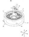
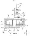
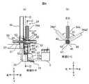
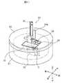
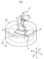
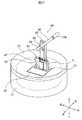
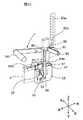
図1から図8は、本発明の第一実施形態に係るもので、図1は試薬ディスク(以下、試薬容器ホルダ、ないしドラムと称することがある)を含む自動分析装置の平面図、図2、図3は試薬ディスクおよび試薬ボトル装填手段の斜視図、図4は試薬ディスクおよび試薬ボトル装填手段の平面図、図5は図2におけるA−A断面図を示している。図6(a)は図4におけるB−B断面図、図6(b)はC−C断面図、図7はD−D断面図、図8は試薬ボトル装填手段の構成を示す分解斜視図である。 1 to 8 relate to the first embodiment of the present invention, and FIG. 1 is a plan view of an automatic analyzer including a reagent disk (hereinafter, may be referred to as a reagent container holder or a drum), FIG. 2. , FIG. 3 is a perspective view of the reagent disc and the reagent bottle loading means, FIG. 4 is a plan view of the reagent disc and the reagent bottle loading means, and FIG. 5 is a sectional view taken along the line AA in FIG. 6 (a) is a sectional view taken along the line BB in FIG. 4, FIG. 6 (b) is a sectional view taken along the line CC, FIG. 7 is a sectional view taken along the line DD, and FIG. 8 is an exploded perspective view showing the configuration of the reagent bottle loading means. Is.
また、以下の説明において、上下左右前後の方向は図1および図2中に示す上下左右前後の方向を基準とする。 Further, in the following description, the directions of up, down, left, right, front and back are based on the directions of up, down, left, right, front and back shown in FIGS. 1 and 2.
図1に示す本実施形態に係る自動分析装置1において、鉛直軸のまわりに回転自在に支持された円筒形の試薬ディスク2の外周壁の内側に沿って、複数の試薬容器(以下、試薬コンテナ、試薬ボトル、ないし単にボトルと称する場合がある)を収納し、それぞれの試薬ボトル3から所定の試薬を所定量だけ、分注ピペットによって吸引して、反応容器内で血液や尿といった生物学的サンプルと混合して分析する機能を備える。自動分析装置1には、例えば後方に向けてヒンジで開閉可能に支持された、可動部分を覆う安全カバー4が設けられている。安全カバー4は図示しない例えばソレノイドなどによる所謂インターロックが設けられており、自動分析装置1の動作中はソレノイドに通電することによって閂をかけ、安全カバー4を閉じた状態に保持する構成である。自動分析装置1の停止中はソレノイドへの通電を解除することで安全カバー4は開放可能となるので、操作者が手動動作で試薬ボトル3を交換することができる。 In the automatic analyzer 1 according to the present embodiment shown in FIG. 1, a plurality of reagent containers (hereinafter, reagent containers) are provided along the inside of the outer peripheral wall of the
試薬ボトル3の内部は、複数の試薬を収納できるよう複数の収納領域に分割されており、それぞれの収納領域の上面は開閉自在な蓋となっている。その構成の詳細は後述する。 The inside of the
まず、分析を行うサンプルの搬送経路について説明する。 First, the transport route of the sample to be analyzed will be described.
分析を行うサンプル5aは、ベルトコンベヤやラックハンドラ等のサンプル搬送手段5によって自動分析装置1内を移動し、サンプルを分注する分注ピペットを備えたサンプル分注手段6まで搬送されて分注される。 The
複数のサンプル分注チップと反応容器は、サンプル分注チップ/反応容器供給手段7に載置された状態で自動分析装置1内に供給され、反応容器はサンプル分注チップ/反応容器搬送手段8によってサンプル分注チップ/反応容器供給手段7からインキュベータ9(培養ディスクと称することもある)へ移動させる。サンプル分注チップ10はサンプル分注チップ/反応容器供給手段7からサンプル分注チップバッファ11まで移動させる。 The plurality of sample dispensing chips and the reaction vessel are supplied into the automatic analyzer 1 in a state of being placed on the sample dispensing chip / reaction
このような移動を可能とするため、サンプル分注チップ/反応容器搬送手段8は、X軸(左右方向)、Y軸(前後方向)およびZ軸(上下方向)方向に移動可能に構成されており、その移動範囲としては、反応容器廃棄孔12、サンプル分注チップバッファ11、反応溶液撹拌手段13、サンプル分注チップ/反応容器供給手段7およびインキュベータ9の一部の上方、の範囲を移動可能に構成されている。 In order to enable such movement, the sample dispensing chip / reaction
サンプル分注チップバッファ11は、複数のサンプル分注チップ10を一時的に載置するバッファであり、サンプル分注手段6はサンプル分注チップバッファ11の上部に移動して、サンプル分注チップ10のいずれか1つを把持する。 The sample
鉛直の中心軸のまわりに回転自在に軸支された円板状のインキュベータ9は、複数の反応容器14を外周近傍の円周上に係止する構成であり、インキュベータ9を回転することによって各々の反応容器14を所定位置まで移動させることができる。 The disk-shaped incubator 9 rotatably supported around the vertical central axis has a configuration in which a plurality of
次にサンプル分注手段6はサンプルの上部領域に移動し、サンプル分注チップ10の内部にサンプルを吸引した後、インキュベータ9上の反応容器14の上部領域へ移動し、サンプルをサンプル分注チップ10内部から反応容器14内に排出する。この後、サンプル分注手段6は、サンプル分注チップ/反応容器廃棄孔12の上部領域に移動し、サンプル分注チップ10を孔の内部に落下して廃棄する。 Next, the sample dispensing means 6 moves to the upper region of the sample, sucks the sample into the
次に、反応容器14内のサンプルに加える試薬の搬送経路について説明する。 Next, the transport route of the reagent added to the sample in the
鉛直の中心軸のまわりに回転自在に軸支された円筒状、かつ内側を空洞とした試薬ディスク2は、内側空洞の外周壁に沿って複数の試薬ボトル3を放射状に保持するスロットを形成しており、試薬ディスク2を回転することで、各試薬ボトル3を円周上の所定位置へ移動させる。なお、試薬ボトル3の一部には、磁気粒子を多数含んだ試薬も含まれる。 The cylindrical and
試薬分注ピペット15は、試薬ボトル3内の試薬を吸引して所定の位置まで移動できるよう、移動可能に構成されている。まず、試薬ディスク2上の所定の種類の試薬の上部領域へ試薬分注ピペット15が移動して所定の量の試薬を吸引した後、インキュベータ9上の所定の反応容器14の上部領域へ移動して試薬を反応容器14内に排出する。 The
試薬ディスク2の上部には、試薬の撹拌手段16が設けられている。この撹拌手段16には、鉛直軸のまわりに回転可能な磁気粒子攪拌アーム(スティラーとも称される)が設けられている。この磁気粒子攪拌アームは、磁気粒子を含んだ攪拌するべき試薬が入っている試薬ボトル3の上部領域へ移動し、磁気粒子攪拌アームの下端に設けられた例えばパドル状ないし螺旋状の磁気粒子攪拌手段を試薬内に下降させ、この磁気粒子攪拌手段を回転させることによって磁気粒子溶液を攪拌する。溶液内の磁気粒子が自然沈殿しないようにするために、磁気粒子攪拌アームは、試薬が分注される直前に磁気粒子を攪拌する。攪拌後、磁気粒子攪拌アームは、試薬ボトル3の上部まで上昇した後、洗浄液が入った洗浄手段17の上部領域へ移動し、洗浄液内に降下した後、磁気粒子攪拌手段を回転させ、この攪拌手段に付着している磁気粒子を取り除く。 A reagent stirring means 16 is provided on the upper part of the
サンプルと所定の試薬を分注してから所定の反応時間が経過した後に、反応溶液が形成される。この反応溶液を反応溶液吸引ノズル18によって反応容器14から吸引し、さらに検出手段19へ供給する。この検出手段19は反応溶液を分析する。 A reaction solution is formed after a predetermined reaction time has elapsed since the sample and the predetermined reagent were dispensed. This reaction solution is sucked from the
次に、分析された反応溶液はサンプル分注チップ/反応容器搬送手段8によってサンプル分注チップ/反応容器廃棄孔12の上部領域まで移動され、サンプル分注チップ/反応容器廃棄孔12内に廃棄する。 Next, the analyzed reaction solution is moved to the upper region of the sample dispensing chip / reaction
装置のこれらの一連の動作は、制御手段であるホストコンピュータ200によって制御される。 These series of operations of the device are controlled by the
この自動分析装置は上記動作を組み合わせ、ないし繰り返すことで、複数の分析項目に関して複数のサンプルを効率的に分析することができる。 By combining or repeating the above operations, this automatic analyzer can efficiently analyze a plurality of samples with respect to a plurality of analysis items.
図2は、本発明にかかわる試薬ディスク2の外観を示す斜視図である。試薬ボトル3を一定の温度に制御するために、試薬ディスク2は断熱機能を有する蓋20とジャケット21により上下面および外周を覆われている。 FIG. 2 is a perspective view showing the appearance of the
蓋20の上面には、本実施形態においてはスライド式に開閉可能な試薬ボトル装填口フタ22を有しており、図2に示すように試薬ボトル装填口フタ22を開放した際には、試薬ボトル装填口23が上面に開口する構成である。試薬ボトル装填口フタ22は図示しないソレノイド等を用いたインターロックが設けられており、安全カバー4と同様、自動分析装置1の動作中にはロックされて閉じた状態であり、自動分析装置1の停止中には解除して開閉可能となる構成である。 In the present embodiment, the upper surface of the
試薬ボトル装填口23の上部領域には、試薬ボトル装填手段24が設けられており、詳細は後述するが、使用者による操作ハンドルを介した手動操作に伴って試薬ボトル3を試薬ディスク2外部から試薬ディスク2内部の所定の位置(以下、試薬ボトル装填スロット26、ないし単にスロットと称することがある)まで、図5に示す試薬ボトル装填経路27に沿って装填する動作、あるいは一部が空になった試薬ボトル3を試薬ディスク2内部のスロットから試薬ディスク2外部に取り出す動作を行うことができる。 A reagent bottle loading means 24 is provided in the upper region of the reagent
図3は、図2に示す斜視図から、蓋20を除いた状態のディスクを示す試薬ディスク2および試薬ボトル装填手段24の外観図である。また、分析時間ないし分析項目のような試薬に関する情報を読み出すための試薬情報読み出し手段25と、を備える。 FIG. 3 is an external view of the
図4は、図3に示した試薬ディスク2の平面図、図5は、試薬ディスク2のA−A断面図である。
試薬ディスク2のうち、試薬分注ピペット15の作動経路上には、試薬分注位置15aと、試薬分注位置15aに隣接して試薬攪拌位置16aとが設けられている。試薬ディスク2のこの領域を処理ゾーンと称することがある。試薬ディスク2の内部にはさらに、隣接した試薬ボトル3の間のスペースを区切ってスロットを形成するための仕切板28を備える。FIG. 4 is a plan view of the
In the
この試薬ディスク2は、試薬ボトル3を所望する位置へ移動するために、試薬ディスク2を回転駆動する試薬ディスク駆動ユニット29を備える。試薬ディスク駆動ユニット29の一例としては、図5に示すようにモータ29aの出力軸に設けられた小プーリ29bと、試薬ディスク駆動軸29cに設けられた大プーリ29dとの間にベルト29eを張架することで、モータ29aの回転を減速して試薬ディスク2を低速で回転する構成である。 The
次に、本実施形態における試薬ボトル装填手段24の構成について、図6から図8により詳細に説明する。 Next, the configuration of the reagent bottle loading means 24 in this embodiment will be described in detail with reference to FIGS. 6 to 8.
試薬ボトル装填手段24は、鉛直に固定された中空円筒状の支柱30に沿って上下方向に移動自在に支持された第一のガイドスリーブ31と、第一のガイドスリーブ31と一体に構成され、第一のガイドスリーブ31と直交して第一のガイドスリーブ31の前方に延伸された中空円筒状の第二のガイドスリーブ32と、第一のガイドスリーブ31と一体に第一のガイドスリーブ31より下部に設けられ、試薬ボトル3を載置する試薬ボトル載置部33と、を備えた装填フレーム35を備えている。 The reagent bottle loading means 24 is integrally formed with a
第一のガイドスリーブ31の上端近傍には、左右方向に貫通した第一のガイドピン穴36が設けられている。支柱30の左右側面には、上下方向に延伸した第一のガイド溝37が開口し、第一のガイドピン穴36と第一のガイド溝37とに第一のガイドピン38が貫通した構成としている。すなわち、支柱30に対して第一のガイドスリーブ31は、回転することなく上下方向にのみ移動可能に支持されている。 A first
支柱30の内周の内側には圧縮ばねであるバランスバネ39を備え、バランスバネ39の下端は支柱30の一部に固定され、バランスバネ39の上端は第一のガイドピン38を下方から付勢するよう構成すれば、バランスバネ39は装填フレーム35を上方に押し上げるので自重と釣合い、落下を防いで操作者が容易に試薬ボトル装填手段24を上下方向に移動可能である。 A
試薬ボトル載置部33は、試薬ボトル3の底面を載置する試薬ボトル載置部底面33aと、試薬ボトル3の側面を保持する試薬ボトル載置部側面33bと、試薬ボトル3の後面を保持する試薬ボトル載置部背面33cと、を備え、試薬ボトル3を載置することができる。 The reagent
操作者が把持して駆動操作する円筒状の操作ハンドル34aの下端部は、前後方向に中空円筒状をなすハンドルスリーブ40となっており、ハンドルスリーブ40の内周は第二のガイドスリーブ32の外周と適度な空隙をもちつつ嵌合して、第二のガイドスリーブ32に沿って前後に摺動可能、かつハンドルスリーブ40の中心軸のまわりに左右に回動可能に支持されている。ハンドルスリーブ40の内周には、上端と下端に一対のガイド突起41が中心軸を向いて設けられており、第二のガイドスリーブ32には各々のガイド突起41に対応した溝が設けられている。 The lower end of the cylindrical operation handle 34a that the operator grips and drives is a
第二のガイドスリーブ32に設けられた溝について説明する。
第二のガイドスリーブ32の上面と下面には、前後方向に一対の第二のガイド溝42が設けられており、第二のガイド溝42にガイド突起41が嵌合することで、ハンドルスリーブ40と操作ハンドル34aとを一体として操作ハンドル34aを正立した位置(中立状態と称することがある)で前後方向に移動可能としている。The groove provided in the
A pair of
第二のガイド溝42と平行に第三のガイド溝43が、第二のガイドスリーブ32の中心軸を挟んで一対設けられており、第三のガイド溝43にガイド突起41が嵌合することで、操作ハンドル34aを左方向に傾斜した状態(試薬ボトル取り外し位置34a1と称することがある)で、ハンドルスリーブ40と操作ハンドル34aとを一体として前後方向に移動可能にしている。 A pair of
第二のガイド溝42の前端には第二のガイド溝42と第三のガイド溝43とを連通した第一の回動ガイド溝44が設けられ、ガイド突起41が第一の回動ガイド溝44と嵌合することで、ハンドルスリーブ40と操作ハンドル34aとを一体として操作ハンドル34aを正立位置と左方向に傾斜した状態34a1との間を回動可能としている。 At the front end of the
第三のガイド溝43の後端には、第二のガイド溝42と第三のガイド溝43とを連通した第二の回動ガイド溝45が設けられ、操作ハンドル34aを左方向に傾斜した状態34a1と正立位置とを回動可能とし、さらに第二の回動ガイド溝45は第二のガイド溝42に対して第三のガイド溝43とは反対側に延伸されており、ハンドルスリーブ40と操作ハンドル34aとを、正立位置からさらに右方向に傾斜した状態(ロック位置34a2と称することがある)まで回動可能としている。 At the rear end of the
第一の回動ガイド溝44と、第二の回動ガイド溝45と、第三のガイド溝43は第二のガイドスリーブ32の内周まで貫通しない有底溝である。一方で第二のガイド溝42は第二のガイドスリーブ32を直径方向に貫通しており、第二のガイド溝42は第二の回動ガイド溝45よりも第一のガイドスリーブ31に近接する側に延伸された、貫通ガイド溝46としている。 The first
試薬ボトル載置部33の上面および、第二のガイドスリーブ32に沿って、前後方向に摺動自在に、試薬ボトル押し出し部47が設けられている。 A reagent
試薬ボトル押し出し部47の上端部は円筒状をなし、かつ前後方向に二分割して設けられた第三のガイドスリーブ48であって、第三のガイドスリーブ48の内周は第二のガイドスリーブ32の外周と適度な空隙をもちつつ嵌合して、前後方向に移動可能に支持されている。二分割して設けられた第三のガイドスリーブ48の間の空隙には、ハンドルスリーブ40が適度な隙間をもちつつ嵌合し、操作ハンドル34aとハンドルスリーブ40を前後方向に移動すれば、第三のガイドスリーブ48を介して試薬ボトル押し出し部47が操作ハンドル34aとともに前後方向に移動する構成である。 The upper end of the reagent
試薬ボトル押し出し部47の前面側には試薬ボトル押し出し面49が設けられている。操作ハンドル34aが最も後方に位置した際には、試薬ボトル押し出し面49は試薬ボトル載置部背面33cと略同一面をなし、その状態で試薬ボトル3を試薬ボトル載置部33に装填できる。 A reagent
試薬ボトル3を試薬ボトル載置部33に装填した状態で操作ハンドル34aを前方に移動すると、操作ハンドル34aとともに試薬ボトル押し出し面49が前方に移動し、試薬ボトル3を前方に押し出す構成である。 When the
第二のガイドスリーブ32の内周には、円筒状のガイドロッド50が前後方向に移動自在に設けられており、第三のガイドスリーブ48の後端近傍と、ガイドロッド50の前端近傍には上下方向に貫通した第二のガイドピン穴51a、51bが設けられ、第二のガイドピン穴51aと第二のガイド溝42と第二のガイドピン穴51bとを貫通して、第二のガイドピン52が設けられている。第二のガイドピン52の直径は第二のガイド溝42の幅よりもわずかに小さく、第二のガイドピン52は第二のガイド溝42および貫通ガイド溝46に嵌合して摺動可能である。 A
すなわち、操作ハンドル34aを前後方向に移動すると、第三のガイドスリーブ48を介して、試薬ボトル押し出し部47とガイドロッド50とが操作ハンドル34aとともに前後方向に移動する構成である。 That is, when the
ハンドルスリーブ40と一体、かつハンドルスリーブ40と平行に、操作ハンドル34aに近接して、後方に向けて延伸したロックピン53が設けられている。ロックピン53は、操作ハンドル34aの左右への回動動作に同期して、ハンドルスリーブ40の中心軸のまわりに回動する構成である。 A
装填フレーム35のうち、ロックピン53に相対する面にはロックピン逃げ溝54が設けられており、ロックピン53の回動を妨げない構成である。支柱30の上端近傍には、ロックピン溝55が設けられており、操作ハンドル34aを後方に移動した位置のままで装填フレーム35を所定の高さまで上昇してから右側に回動してロック位置とすると、ロックピン53がロックピン溝55に嵌合する構成としている。したがって、装填フレーム35を上昇位置でロックして、下降しないよう保持することができる。このとき、図5に示すように試薬ボトル載置部底面33aが試薬ボトル装填口23よりも位置が高くなるように構成すれば、操作者が試薬ボトル3を試薬ボトル載置部33に装着ないし取り外す作業がし易く、使いやすい自動分析装置を提供できる。 A lock
ここで、試薬ボトル装填手段24を用いて試薬ボトル3を試薬ディスク2内に装填する際の、試薬ボトル3の軌跡である試薬ボトル装填経路27について説明する。図5に示すように、まず操作ハンドル34aを最も後方かつ上方に移動して装填フレーム35を上昇位置でロックした状態から、試薬ディスク2内に鉛直に下降する。次に、最も下降した位置で進行方向を試薬ディスク2の外周に向けて前方に転換して、試薬ボトル3が試薬ディスク2の外周に設けられた試薬ボトル装填スロット26に挿入されるまで移動するので、略L字形状の軌跡となる。 Here, the reagent
すなわち、略L字形状の軌跡を実現するために、操作ハンドル34aが最後方にある際にのみ上下方向の移動を可能とし、操作ハンドル34aが最下方にある際にのみ前後方向の移動を可能とするよう構成したい。そのような構成の一例として、支柱30の下端近傍で、ガイドロッド50に近接した左側を前後方向に円筒状に切欠いた第一の閂溝56を設ける。この第一の閂溝56には、ガイドロッド50の円筒外周が適度な隙間をもって勘合して、第一の閂溝56に沿ってガイドロッド50が前後方向に摺動可能に構成されている。すなわち、装填フレーム35が最下方にあって第一の閂溝56がガイドロッド50の外周に嵌合した位置においてのみ、試薬ボトル装填手段24は前後方向に摺動可能となる。 That is, in order to realize a substantially L-shaped locus, it is possible to move in the vertical direction only when the
ガイドロッド50の前端近傍には、支柱30に近接した右側を上下方向に円筒状に切欠いた第二の閂溝57を設ける。この第二の閂溝57には、支柱30の円筒外周が適度な隙間をもって勘合して、第二の閂溝57が支柱30に沿って上下方向に摺動可能に構成されている。すなわち、操作ハンドル34aが最後方にあって第二の閂溝57が支柱30の外周に嵌合した位置においてのみ、試薬ボトル装填手段24は上下方向に摺動可能となる。 In the vicinity of the front end of the
すなわち、第一の閂溝56と第二の閂溝57とを設けることにより、操作ハンドル34aが最後方にある際にのみ上下方向の移動を可能とし、操作ハンドル34aが最下方にある際にのみ前後方向の移動を可能として、試薬ボトル装填手段24を略L字型の軌跡に沿って動作する、望ましい動作を実現可能な構成である。 That is, by providing the
試薬ボトル3は、内部に試薬を封入され、上面に開口であるボトル開口58を備えた複数の試薬容器59を前後方向に一列に併置したボトル部60と、それぞれのボトル開口58に対応して設けられたヒンジ61のまわりに開閉自在に支持され、それぞれのボトル開口58を開閉自在な蓋であるキャップ62を備えている。 The
試薬ボトル3の一部には、例えば分析時間ないし分析項目のような試薬に関する情報を記載したRFID(Radio Frequency IDentification:無線周波数認識装置)タグやバーコードラベルなどの情報記録媒体を設けてもよく、試薬ディスク2の外部に設けられた試薬情報読み出し手段25を介して記載された情報を読み取ることができる。 A part of the
次に、試薬ディスク2内に装填された試薬ボトル3が空になった後、空の試薬ボトル3を引き出すために作用する試薬ボトル引き出し手段63aについて説明する。 Next, the reagent bottle withdrawal means 63a, which acts to withdraw the
試薬ボトル引き出し手段63aは試薬ボトル押し出し部47と第三のガイドスリーブ48との間に前後方向に設けられた回転支軸穴119に嵌合した回転支軸64aのまわりに回動自在に軸支されており、回転支軸64aより下側には試薬ボトル3に近接する方向に凸した試薬ボトル引き出し突起65aが設けられ、回転支軸64aより上側は回転支軸64aから離反する方向に凸した操作板66が設けられ、操作板66は、先端が試薬ボトル押し出し部47に近接する方向に傾斜して設けられている。 The reagent bottle withdrawal means 63a is rotatably supported around a
回転支軸64aには、試薬ボトル引き出し手段63aに図示反時計方向、すなわち試薬ボトル引き出し突起65aが試薬ボトル3から離反する向きに回動するトルクを付与するトーションスプリング68が設けられている。 The
ハンドルスリーブ40には操作板66と互いに作用する操作突起67が設けられており、図7(a)に示すように操作ハンドル34aが中立ないし右側に傾斜したロック位置にある場合には、操作突起67は操作板66に作用せず、トーションスプリング68からの回動トルクによって、試薬ボトル引き出し突起65aは試薬ボトル3から離反した位置にある。すなわち、この状態で操作ハンドル34aを前方に移動すれば、試薬ボトル押し出し面49を介して試薬ボトル3を後方から前方に押し出すことはできるが、操作ハンドル34aを前方から後方に移動しても試薬ボトル3をスロットから後方に引き出すことはできず、試薬ボトル押し出し部47のみが後方に移動する。 The
一方、図7(b)に示すように操作ハンドル34aを左側に傾斜して試薬ボトル取り外し位置34a1とし、ガイド突起41が第三のガイド溝43と勘合した状態とすれば、操作突起67が操作板66に作用して回転支軸64aのまわりに回動し、試薬ボトル引き出し突起65が試薬ボトル3のヒンジ61とボトル開口58との間に挿入される。この状態で操作ハンドル34aを後方に移動すると、試薬ボトル引き出し突起65aが試薬ボトル3を後方に引くことができる。ここで、操作ハンドル34aを後方に移動すれば、試薬ディスク2のスロットに装填された試薬ボトル3を試薬ディスク2の内周側に向けて引き出すことができるので、試薬ボトル把持手段として作用する。 On the other hand, as shown in FIG. 7B, if the
試薬ボトル押し出し面49の下側には、試薬ボトル3の前後方向を逆向きに挿入できないよう、試薬ボトル3の向きを判定する方向判定レバー69と、方向判定レバー69に所定のトルクを付与するトーションスプリング70が設けられているが、その詳細は後述する。 A predetermined torque is applied to the
試薬ボトル載置部側面33bには、上下方向に設けられた二重装填防止アーム軸72のまわりに回動自在に軸支され、トーションスプリング75によって所定の回転方向に付勢された試薬ボトル検知アーム73が設けられており、試薬ボトル載置部底面33aの下面に配置された二重装填防止アーム74と連動して回動する構成である。この二重装填防止アーム74は、試薬ディスク2の空でないスロットに誤って別の試薬ボトル3を重ねて装着しないための二重装填防止手段71を構成しているが、その詳細は後述する。
A reagent bottle rotatably supported around a double loading
次に、本実施形態における試薬ボトル装填手段24を用いた試薬ボトル3の試薬ディスク2への装着工程と、空になった試薬ボトル3の試薬ディスク2からの取り外し工程を説明する。 Next, a step of attaching the
まず、本実施形態における試薬ボトル装填手段24の状態を、図9から図16までの斜視図と、図17から図19の断面図を用いて下記のように表記するものとする。なお、図17から図19の断面図においては、操作ハンドル34aは正立した状態とともに、傾斜した状態も含むものとして説明する。 First, the state of the reagent bottle loading means 24 in the present embodiment is described as follows using the perspective views of FIGS. 9 to 16 and the cross-sectional views of FIGS. 17 to 19. In the cross-sectional views of FIGS. 17 to 19, the
1.第一の状態(図9):試薬ボトル装填手段24は上端位置にあり、操作ハンドル34aは最も後方で右側に傾斜して、ロックピン53がロックピン溝55に嵌合して、試薬ボトル装填手段24を上端でロックした状態にある。さらに、試薬ボトル装填口フタ22は閉止した状態である。 1. 1. First state (FIG. 9): The reagent bottle loading means 24 is in the upper end position, the
2.第二の状態(図10):試薬ボトル装填手段24は上端位置にあるものの操作ハンドル34aは最も後方で正立位置にあってロックピン53はロックピン溝55から外れて、試薬ボトル装填手段24の上端でのロックは解除されている。試薬ボトル3は試薬ボトル載置部33に載置されており、試薬ボトル装填口フタ22は開いて、試薬ボトル装填口23が開口した状態である。 2. 2. Second state (FIG. 10): The reagent bottle loading means 24 is in the upper end position, but the
3.第三の状態(図11、図17):試薬ボトル装填手段24は最も下降した状態であり、操作ハンドル34aは最も後方で正立位置にある。第二の状態から第三の状態においては、第二の閂溝57は支柱30の外周と嵌合しており、操作ハンドル34aは上下方向には移動できるが、前後方向には移動できない構成である。 3. 3. Third state (FIGS. 11 and 17): The reagent bottle loading means 24 is in the most lowered state, and the
4.第四の状態(図12、図18):試薬ボトル装填手段24は最も下降した状態であり、かつ操作ハンドル34aは最も手前で正立位置にある。試薬ボトル3は試薬ボトル押し出し部47によって操作ハンドル34aとともに前方に移動し、試薬ディスク2の試薬ボトル装填スロット26に挿入されて、試薬ディスク2の外周に沿った装填位置にある。 4. Fourth state (FIGS. 12 and 18): The reagent bottle loading means 24 is in the most lowered state, and the
5.第五の状態(図13、図19):試薬ボトル装填手段24は最も下降した状態であり、操作ハンドル34aは最も後方で正立位置にある。試薬ボトル3は試薬ボトル装填スロット26に挿入された装填位置に装填されており、試薬ボトル装填手段24は空の状態である。第三の状態から第四の状態の状態、さらに第五の状態においては、第一の閂溝56はガイドロッド50の外周と嵌合しており、操作ハンドル34aは前後方向には移動できるが、上下方向には移動できない構成である。 5. Fifth state (FIGS. 13 and 19): The reagent bottle loading means 24 is in the most lowered state, and the
6.第六の状態(図14、図18):試薬ボトル装填手段24は装填状態1と同じく上端位置にあり、操作ハンドル34aは最も後方で正立位置にある。試薬ボトル3は試薬ディスク2の外周に沿った試薬ボトル装填スロット26に装填されており、試薬ボトル装填手段24は空の状態である。 6. Sixth state (FIGS. 14 and 18): The reagent bottle loading means 24 is in the upper end position as in the loading state 1, and the
7.第七の状態(図15、図17):試薬ボトル装填手段24は最も下降し、操作ハンドル34aは最も手前位置で左側に傾斜して、操作突起67を介して試薬ボトル引き出し手段63が試薬ボトル3に作用した状態である。 7. Seventh state (FIGS. 15 and 17): The reagent bottle loading means 24 is lowered most, the
8.第八の状態(図16):試薬ボトル装填手段24は最も下降し、操作ハンドル34aは左側に傾斜した状態で、試薬ボトル引き出し手段63aが試薬ボトル3に作用したまま最も後方に移動した状態である。試薬ボトル3は試薬ボトル引き出し手段63aの作用によって試薬ボトル装填スロット26から引き出され、操作ハンドル34aとともに後方に移動して、試薬ボトル載置部33に載置された状態である。
8. Eighth state (FIG. 16): The reagent bottle loading means 24 is lowered most, the
次に、本実施形態における試薬ボトル装填手段24を用いて、試薬ボトル3を試薬ディスク2内の空きスロットに装填する一連の動作を説明する。 Next, a series of operations of loading the
自動分析装置1が駆動されており、試薬ディスク2内の試薬ボトル3を用いて試薬を分注し、サンプルを分析する動作を行っている間は、試薬ボトル装填手段24は第一状態にある。 While the automatic analyzer 1 is driven, the reagent is dispensed using the
試薬ディスク2内に、試薬ボトル3の装填されていない空きスロットがあって、その空きスロットに新たな試薬ボトル3を装填する際には、まず自動分析装置1を停止してインターロックを解除し、安全カバー4を開く。次に、試薬ボトル装填口フタ22を開く。新たな試薬ボトル3を試薬ボトル載置部33に載置して、操作ハンドル34aを正立位置として第二状態となる。 When there is an empty slot in the
第二状態から操作ハンドル34aを下方に移動して、試薬ボトル3の載置された試薬ボトル装填手段24を下降させて第三状態とする。 The
第三状態から操作ハンドル34aを手前に引いて、試薬ボトル押し出し部47を前方に移動することで、試薬ボトル3を空きスロット内に挿入する。試薬ボトル3は試薬ディスク2の外周内側に沿った所定の位置まで押し込まれて第四状態となる。試薬ボトル3は操作ハンドル34aの駆動操作に応じて所定の位置まで移動するので、装填完了した際の位置ばらつきが少なく、精度よく試薬ボトル3を装填できる。 The
第四状態から操作ハンドル34aを後方に押して、試薬ボトル押し出し部47を後方に移動する。試薬ボトル3は試薬ディスク2内の所定の位置に留まり、第五状態となる。 From the fourth state, the
第五状態から、操作ハンドル34aを上方に移動して、試薬ボトル押し出し部47を上方に移動し、第六状態となる。 From the fifth state, the
その後、操作ハンドル34aを右側に傾斜してロックピン53をロックピン溝55に嵌合させて、試薬ボトル装填手段24を上端でロックし、さらに試薬ボトル装填口フタ22を閉止すれば、第一状態に戻るので、安全カバー4を閉じれば自動分析装置1を駆動可能な状態となる。 After that, the
次に、本実施形態における試薬ボトル装填手段24を用いて、空になった試薬ボトル3を試薬ディスク2内から取り出す一連の動作を説明する。 Next, a series of operations for taking out the
自動分析装置1が駆動されており、試薬ディスク2内の試薬ボトル3を用いて試薬を分注し、サンプルを分析する動作を行っている最中は、試薬ボトル装填手段24は第一状態にある。 While the automatic analyzer 1 is being driven, the reagent is dispensed using the
空になった試薬ボトル3を試薬ディスク2内から取り出す際には、まず自動分析装置1を停止してインターロックを解除し、安全カバー4を開く。次に、試薬ボトル装填口フタ22を開く。試薬ボトル載置部33は空のままで操作ハンドル34aを正立位置として、第六状態とする。 When removing the
第六状態から操作ハンドル34aを下方に移動して、試薬ボトル装填手段24を下降させて第五状態とする。 The
第五状態から操作ハンドル34aを手前に引いて、試薬ボトル押し出し部47を前方に移動することで、試薬ボトル押し出し面49は試薬ボトル3に接して、第四状態となる。 By pulling the
第四状態から操作ハンドル34aを左側に傾斜させ試薬ボトル取り外し位置34a1とすることで試薬ボトル引き出し手段63aを作用させて、第七状態とする。 By tilting the operation handle 34a to the left from the fourth state and setting the reagent bottle removal position 34a1, the reagent bottle withdrawal means 63a operates to obtain the seventh state.
第七状態から操作ハンドル34aを左側に傾斜させたまま後方に移動することで、空の試薬ボトル3は試薬ボトル引き出し手段63aの作用によって、試薬ディスク2のスロットから後方に引き出され、試薬ボトル載置部33に載置されて第八状態となる。 By moving the operation handle 34a backward from the seventh state while tilting the operation handle 34a to the left, the
第八状態から、操作ハンドル34aを正立位置に戻すことで、第三状態となる。 By returning the operation handle 34a to the upright position from the eighth state, the third state is reached.
第三状態から、操作ハンドル34aを上方に移動して、試薬ボトル押し出し部47を上方に移動し、第二状態となる。 From the third state, the
第二状態から、操作ハンドル34aを右側に傾斜してロックピン53をロックピン溝55に嵌合させて、試薬ボトル装填手段24を上端でロックし、空の試薬ボトル3を操作者が取り外して、試薬ボトル装填口フタ22を閉じれば第一の状態に戻るので、取り出し動作が完了する。 From the second state, the
空の試薬ボトル3を取り外した後、新たな試薬ボトル3を載置して、引き続き試薬ボトル装填動作を行うことで、試薬ボトル3を交換することができる。 After removing the
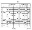
次に、図20のタイムチャートを用いて、試薬ボトル3の装填と取り外し動作の際の各部の動作方向と動作タイミングの概要について説明する。 Next, using the time chart of FIG. 20, the outline of the operation direction and the operation timing of each part during the loading and unloading operation of the
タイムチャートの左半分(A)は、試薬ボトル3を試薬ディスク2に装填するまでの装填工程を示し、タイムチャートの右半分(B)は、空の試薬ボトル3を試薬ディスク2から取り外す工程を示す。
丸数字の1から8は、先に説明した試薬ボトル装填手段24の状態を示し、それぞれ第一状態から第八状態までに対応している。
(a)は、操作ハンドル34aの左右への傾斜動作を示し、右傾斜のときは支柱30との間でロックし、左傾斜の時は試薬ボトル引き出し手段63に作用する。
(b)は、操作ハンドル34aの上下の動きを示す。
(c)は、操作ハンドル34aの前後の動きを示す。
(d)は、試薬ボトル載置部33の上下の動きを示し、操作ハンドル34aとともに上下移動する構成だから、(b)の操作ハンドル34aの上下の動きと同一となる。
(e)は、試薬ボトル載置部33の前後の動きを示し、操作ハンドル34aとともに前後移動する構成だから、(c)の操作ハンドル34aの前後の動きと同一となる。
(f)は、試薬ボトル引き出し手段63aの動作を示し、試薬ボトル引き出し手段63aが試薬ボトル3に作用している間は、試薬ボトル載置部33が後方に移動する際に、空の試薬ボトル3を試薬ディスク2のスロットから引き出すことができる。The left half (A) of the time chart shows the loading process until the
The circled numbers 1 to 8 indicate the states of the reagent bottle loading means 24 described above, and correspond to the first state to the eighth state, respectively.
(A) shows the operation of tilting the operation handle 34a to the left and right, locks the
(B) shows the vertical movement of the
(C) shows the front-back movement of the
(D) shows the vertical movement of the reagent
(E) shows the front-back movement of the reagent
(F) shows the operation of the reagent bottle withdrawal means 63a, and while the reagent bottle withdrawal means 63a is acting on the
試薬ボトル3を装填する際には、まず、操作ハンドル34aを右傾斜した第一状態から正立した第二状態とし、さらに操作ハンドル34aを下方に下降して第三状態とする。次に、操作ハンドル34aを前方に移動して第四状態とすれば、試薬ボトル3は試薬ディスク2内の空きスロット内に挿入されて装填される。 When loading the
その後、操作ハンドル34aを後方に移動して第五状態、さらに上方に移動して第六状態を経て、操作ハンドル34aを正立から右方に傾斜して試薬ボトル装填手段24を最上端の位置でロックして、再び第一状態となる。 After that, the
試薬ボトル3を取り外す際には、まず、操作ハンドル34aを右傾斜した第一状態から正立した第六状態とし、さらに操作ハンドル34aを下方に下降して第五状態とする。次に、操作ハンドル34aを前方に移動して第4状態とし、さらに操作ハンドル34aを左側に傾斜して第七状態とすれば、試薬ボトル引き出し手段63が試薬ボトル3に作用する。引き続き操作ハンドル34aを後方に移動すると、試薬ボトル3は試薬ディスク2内のスロットから引き出されて第八状態となる。操作ハンドル34aを正立位置に戻して第三状態とし、さらに上方に移動して第二状態を経て、操作ハンドル34aを正立から右方に傾斜して試薬ボトル装填手段24を最上端の位置でロックして、再び第一状態となる。 When removing the
<逆挿入防止>
次に、図21と図22を用いて、試薬ボトル3を試薬ボトル載置部33に装填する際に、正規な向きでは装填できるが、操作者が誤って逆向きに装填しようとした際には、試薬ボトル3の装填を妨げて、操作者に試薬ボトル3の向きが逆向きであることを認知させるための方向判定レバー69を備えた逆挿入防止手段76について説明する。なお、本実施形態において、試薬ボトル3は、キャップ62のヒンジ61が試薬ボトル載置部背面33cに近接する方向に挿入することを正規な方向である、とする。<Prevention of reverse insertion>
Next, when the
図21は、試薬ボトル3を正規な向きで試薬ボトル載置部33に装填する際の動作を説明する図であり、(a)から(c)は平面図、(d)は斜視図である。 21A and 21B are views for explaining the operation when the
図22は、試薬ボトル3を逆向きで試薬ボトル載置部33に装填しようとした際の動作を説明する図であり、(a)は平面図、(b)は斜視図である。 22A and 22B are views for explaining the operation when the
方向判定レバー69は、試薬ボトルを逆向きに装填しようとした際には試薬容器の挿入を阻止する、試薬容器逆方向挿入阻止手段として作用する。方向判定レバー69は、回転支軸79のまわりに回動自在に軸支され、第一の突起であるヒンジ検知突起77と第二の突起であるストッパ突起78とを備え、矢印方向にトーションスプリング70による回転トルクによって付勢されている。 The
ストッパ突起78は試薬ボトル載置部側面33bに沿って、試薬ボトル3のボトル部上面80よりも下方にて試薬ボトル3の左側面近傍に当接するよう配置されている。 The
ヒンジ検知突起77は、試薬ボトル3のボトル部上面80よりも上部でヒンジ61近傍に当接するように配置され、かつストッパ突起78より長く、試薬ボトル3の左右方向の中央近傍に向くよう、ストッパ突起78から傾斜して延伸されている。 The
図21(a)ないし(d)において、正規な向きで試薬ボトル3を装填しようとすると、最初に試薬ボトル3の後面にあるヒンジ61の近傍がヒンジ検知突起77に当接する。この接触点は回転支軸79よりも右方に寄っているから、方向判定レバー69を回転支軸79のまわりに反時計方向に回転させようとする反力を生じ、図21(b)に示すように方向判定レバー69は回動する。方向判定レバー69が試薬ボトル3に押されて回動を続けると、長さの短いストッパ突起78の先端が試薬ボトル3の後面に当接し、その後も方向判定レバー69はさらに回動して図21(c)に示した位置、すなわち試薬ボトル3の後面が試薬ボトル載置部背面33cに当接して、試薬ボトル3が試薬ボトル載置部33に正しく装填される。 In FIGS. 21 (a) to 21 (d), when the
一方、図22(a)ないし(b)に示すように、試薬ボトル3を前後逆向き、すなわちヒンジ61が前面を向いた向きに装填しようとした場合には、ヒンジ検知突起77はヒンジ61近傍に当接しないので方向判定レバー69は回動することなく、ストッパ突起78が試薬ボトル3の後面に略垂直に当接して所謂つっかえ棒となり、試薬ボトル3がそれ以上後方に移動できない。操作者は試薬ボトル3を後方一杯まで押し込むことができないことから、試薬ボトル3が逆向きになっていることに気づく。 On the other hand, as shown in FIGS. 22 (a) to 22 (b), when the
以上の逆挿入防止手段76を備えたことにより、試薬ボトル3の向きが正しいか逆か、を簡素な構成で容易に操作者に知らしめることができるので、逆向きに試薬ボトル3を装填することがなく、使い易く信頼性の高い自動分析装置を提供できる。 By providing the above-mentioned reverse
図23と図24を用いて、既に試薬ボトル3が装填されているスロットに、誤って別の試薬ボトル3を重ねて装填(これを、二重装填と称する場合がある)しないための二重装填防止手段71の構成について説明する。 23 and 24 are used to prevent accidentally stacking another
試薬ボトル3を供給する作業は、試薬ディスク2に装填された試薬ボトル3のいずれかが空になり、空の試薬ボトル3を取り外した後の空いたスロットに新たな試薬ボトル3を供給するか、あるいは元々の空きスロットに新たな試薬ボトル3を供給する際に行われる。 In the operation of supplying the
ここで、空きスロットと判定したにもかかわらず実際には試薬ディスク2に試薬ボトル3が入っていた場合、既に装填されている試薬ボトル3の上面に、新たに装填しようとする試薬ボトル3の底面が当たって、新たに装填しようとする試薬ボトル3が押し上げられて外れ、試薬ディスク2内に落下する恐れがある。このような事態を回避するための二重装填防止手段71の構成の一例について、説明する。 Here, if the
図23と図24は、試薬ボトルの二重装填防止手段71の構成を示す、それぞれ(a)斜視図と(b)平面図である。
試薬ボトル載置部側面33bの一部には、二重装填防止アーム軸72のまわりに回動自在に軸支された試薬ボトル検知アーム73が設けられており、二重装填防止アーム軸72は試薬ボトル載置部底面33aよりも下方に延伸され、二重装填防止アーム74が設けられている。試薬ボトル検知アーム73はトーションスプリング75によって、図示反時計方向に付勢されている。23 and 24 are (a) a perspective view and (b) a plan view showing the configuration of the reagent bottle double loading prevention means 71, respectively.
A reagent
図23は、試薬ディスク2内に試薬ボトル3が隣接したスロットに既に装填されており、空になった試薬ボトル3を引き出すために、第六状態から第五状態に、操作ハンドル34aによって試薬ボトル載置部33を試薬ディスク2内に下降させる際の形態を示している。 In FIG. 23, the
試薬ボトル載置部33に試薬ボトル3は装填されていないので、試薬ボトル検知アーム73は、トーションスプリング75の付勢力によって試薬ボトル載置部側面33bから突出した位置にある。このとき二重装填防止アーム74は、図23(b)の平面視で空になった試薬ボトル3と、隣接した試薬ボトル3との間の空隙に位置するよう配置されており、試薬ボトル載置部33を下降して第五状態にすることができる。すなわち、空になった試薬ボトル3を引き出す目的で試薬ボトル載置部33が空の状態では、試薬ボトル載置部33を下降することができる。 Since the
一方、図24は、試薬ディスク2に空きスロットが無く、試薬ボトル3が既に装填されているにも関わらず、試薬ボトル載置部33に新たな試薬ボトル3(一点鎖線で示す)を装填してスロットに装填しようとした場合を示している。試薬ボトル載置部側面33bに沿って試薬ボトル3が装填されているために、試薬ボトル検知アーム73はトーションスプリング75の付勢力に抗って図示時計方向に回動し、二重装填防止アーム74の先端は、図24(b)の平面視で、既に装填されている試薬ボトル3と重なる位置に移動する。 On the other hand, in FIG. 24, although there is no empty slot in the
すると、試薬ボトル載置部33を下降しようとした際には二重装填防止アーム74の先端が既に装填されている試薬ボトル3の上面に当接するので、試薬ボトル載置部33はそれ以上に下降することができず、操作ハンドル34aを下降しようとする操作者に、試薬ディスク2が空でないことを知らしめることができる。 Then, when the reagent
さらにこのとき、既に装填されている試薬ボトル3の上面に当接して反力を受けるのは、試薬ボトル載置部底面33aよりも下方に設けられた二重装填防止アーム74なので、試薬ボトル載置部33に載置された試薬ボトル3には力が加わることはなく、新たに装填しようとする試薬ボトル3が押し上げられて外れることはない。 Further, at this time, it is the double
以上の二重装填防止手段71を備えたので、次に装填しようとしている試薬ディスク2内のスロットが空であるか否か、を簡素な構成で容易に操作者に知らしめることができるので、二重に試薬ボトル3を装填することがなく、使い易く信頼性の高い自動分析装置1を提供できる。 Since the above double loading prevention means 71 is provided, it is possible to easily notify the operator with a simple configuration whether or not the slot in the
図25のフローチャートを用いて、第一実施形態において試薬ディスク2内の空きスロットに新たに試薬ボトル3を装填する工程について説明する。 The step of newly loading the
ステップS101
装填工程の開始に伴って、空きスロットの有無を確認して、処理を分岐する。Step S101
With the start of the loading process, the presence or absence of empty slots is confirmed, and the process is branched.
ステップS102
試薬ディスク2内の空きスロットがあった場合には、その空きスロットの位置を確認する。Step S102
If there is an empty slot in the
ステップS103
試薬ディスク2を回転して、空きスロットを試薬ボトル装填手段24による装填位置に移動して停止する。Step S103
The
ステップS104
動作を停止してインターロックを解除し、安全カバー4と試薬ボトル装填口フタ22とを開放可能な状態とする。Step S104
The operation is stopped and the interlock is released so that the safety cover 4 and the reagent bottle
ステップS105
安全カバー4を開く。Step S105
Open the safety cover 4.
ステップS106
試薬ボトル装填口フタ22を開く。Step S106
Open the reagent bottle
ステップS107
試薬ボトル3を試薬ボトル装填手段24に装填する。Step S107
The
ステップS108
操作ハンドル34aを操作して、試薬ボトル3を試薬ディスク2の空きスロット内に装填し、試薬ボトル装填手段24を元の位置に戻してロックする。Step S108
The
ステップS109
試薬ボトル装填口フタ22を閉じる。Step S109
Close the reagent bottle
ステップS110
安全カバー4を閉じる。Step S110
Close the safety cover 4.
ステップS111
安全カバー4が閉じられたことを検知するか、あるいは操作者が試薬ボトル3の装填が完了したことを、図示しない操作手段から操作したら、インターロックを作動して、安全カバー4と試薬ボトル装填口フタ22とをロックする。Step S111
When it is detected that the safety cover 4 is closed or the operator operates from an operation means (not shown) that the loading of the
ステップS112
新たに装填された試薬ボトル3を例えばRFIDリーダである試薬情報読み出し手段25の位置まで回動する。Step S112
The newly loaded
ステップS113
試薬ボトル3の試薬情報を読み取る。Step S113
Read the reagent information of the
以上で、試薬ディスク2の空きスロット内に、新たに試薬ボトル3の装填工程が完了する。上記のステップのうち、安全カバー4を開くステップS105から、安全カバー4を閉じるステップS110までは操作者による手動動作であって、手動動作に従って試薬ボトル3の装填を行うことができ、同様に試薬ボトル3を試薬ディスク2から取り外すこともできる構成である。 With the above, the loading process of the
以上のように、操作者の手動動作によって試薬ボトル3の装填および取り出しを行うことができる構成としたので、構造の簡素化や小型化が実現でき、さらに動作制御アルゴリズムを簡素化することができる。 As described above, since the
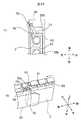
次に、本発明の第二実施形態について図26から図35により説明する。図26から図33は試薬ボトル装填手段24の第二実施形態を示す斜視図である。 Next, the second embodiment of the present invention will be described with reference to FIGS. 26 to 35. 26 to 33 are perspective views showing a second embodiment of the reagent bottle loading means 24.
第二実施形態が第一実施形態と異なるところは、操作ハンドル34bを左右方向に延伸した円筒状としたことと、試薬ボトル引き出し突起65が試薬ボトル3に対して作用する、試薬ボトル引き出し手段63の動作を、操作ハンドル34bの傾斜動作ではなく、アクチュエータとしてソレノイド81を設け、ソレノイド81への通電によって行うことである。また、操作ハンドル34bから試薬ボトル載置部33までの駆動リンク機構が異なることによって、操作ハンドル34bの動作を異なるものとしたので以下説明する。 The second embodiment is different from the first embodiment in that the
図26は第一実施形態の第一状態に相当し、試薬ボトル3を装填する前の状態を示す。 FIG. 26 corresponds to the first state of the first embodiment and shows the state before loading the
図27は第一実施形態の第二状態に相当し、試薬ボトル載置部33に試薬ボトル3を装填した状態を示す。試薬ボトル3が試薬ディスク2内に装填された位置にあれば、第一実施形態の第六状態に相当する。 FIG. 27 corresponds to the second state of the first embodiment, and shows a state in which the
図28は図26を右上方向から見た斜視図である。 FIG. 28 is a perspective view of FIG. 26 as viewed from the upper right direction.
図29は図28に示す斜視図において、試薬ボトル装填手段24のみを示す斜視図であり、一部を省略して内部構造を記載している。 FIG. 29 is a perspective view showing only the reagent bottle loading means 24 in the perspective view shown in FIG. 28, and a part thereof is omitted to describe the internal structure.
図30は第一実施形態の第三状態に相当し、図31は図30を右上方向から見た斜視図であって、試薬ボトル3を試薬ディスク2内に下降した状態を示す。試薬ボトル3が試薬ディスク2内に装填された位置にあれば、第一実施形態の第五状態に相当する。 FIG. 30 corresponds to the third state of the first embodiment, and FIG. 31 is a perspective view of FIG. 30 viewed from the upper right direction, showing a state in which the
図32は第一実施形態の第四状態に相当し、図33は図32を右上方向から見た斜視図であって、試薬ボトル3を試薬ディスク2内に装填完了した状態を示す。 FIG. 32 corresponds to the fourth state of the first embodiment, and FIG. 33 is a perspective view of FIG. 32 viewed from the upper right direction, showing a state in which the
図34はソレノイド81を用いて試薬ボトル引き出し突起65を試薬ボトル3に対して作用する、試薬ボトル把持手段の構成と動作を詳細に説明する斜視図である。 FIG. 34 is a perspective view for explaining in detail the configuration and operation of the reagent bottle gripping means in which the reagent bottle pull-out
図34(a)は第一実施形態の第八状態に相当し、ソレノイド81に通電せず、試薬ボトル引き出し突起65が試薬ボトル3に対して作用していない状態、
図34(b)は第一実施形態の第七状態に相当し、ソレノイド81に通電して、試薬ボトル引き出し突起65が試薬ボトル3に対して作用した状態を示している。FIG. 34A corresponds to the eighth state of the first embodiment, in which the
FIG. 34B corresponds to the seventh state of the first embodiment, and shows a state in which the reagent bottle pull-out
<試薬ボトル装填手段>
第二実施形態における試薬ボトル装填手段24の構成について説明する。固定して設けられた角型の支柱82には、鉛直部83aと鉛直部83aの下部に鉛直部83aに連続して設けられた円弧部83bとを備えたガイドレール83を備えている。<Reagent bottle loading means>
The configuration of the reagent bottle loading means 24 in the second embodiment will be described. The fixed
円筒状の操作ハンドル34bは、試薬ボトル載置部33の一部を上側かつ後方に延伸して設けられた操作ハンドル支軸84のまわりに回動自在に軸支されたハンドルアーム85の前側先端に左右方向に水平に設けられている。 The
操作ハンドル支軸84のまわりには、先端にガイドピン86を設けたガイドアーム87がハンドルアーム85と一体として回転するよう設けられている。ガイドピン86はガイドレール83に摺動自在に勘合して、ガイドレール83に沿って移動可能な構成である。 A
試薬ボトル載置部33の下端近傍に試薬ボトル3を装填する。試薬ボトル3の後部には、試薬ボトル載置部33に対して前後方向に摺動自在に支持された試薬ボトル押し出し部47が設けられ、試薬ボトル押し出し部47が前方に向けて移動すると試薬ボトル3を試薬ボトル載置部33から試薬ディスク2の内側に向けて押出して、試薬ディスク2の試薬ボトル装填スロット26に試薬ボトル3を装填することができる。 The
図28から図31に示すように、操作ハンドル34bを下方に向けて鉛直に移動すると、ガイドピン86はガイドレール鉛直部83aに沿って下方に移動するので、ガイドアーム87は回動することなく鉛直に下方に移動する。したがって試薬ボトル載置部33は操作ハンドル34bとともに下方に移動し、試薬ディスク2は試薬ボトル装填口23から試薬ディスク2内に下降する。 As shown in FIGS. 28 to 31, when the
図29から図31に示すように、試薬ボトル装填手段24の内部には上下方向に延伸したプッシュロッド88が設けられ、上端はハンドルアーム85に設けられたプッシュロッド上端支軸89に回動可能に軸支されている。試薬ボトル載置部33の下端近傍には、ベルクランク支点90のまわりに回動自在に軸支された略L字型のベルクランク91が設けられ、第一のベルクランク軸92において、ベルクランク91の一端とプッシュロッド88の下端とは回転自在に軸支されている。ベルクランク91の他端は第二のベルクランク軸93となっており、試薬ボトル押し出し部47の後端近傍から下側に延伸して設けられた上下方向の溝である試薬ボトル押し出し溝94に摺動自在に嵌合した構成である。 As shown in FIGS. 29 to 31, a
次に、図32および図33に示すように、操作ハンドル34bをさらに下方に向けて操作すると、ガイドピン86はガイドレール円弧部83bに沿って操作ハンドル支軸84のまわりに回動する。したがって、ハンドルアーム85は下降することなく操作ハンドル支軸84のまわりに回動し、プッシュロッド88は下降してベルクランク91をベルクランク支点90のまわりに図33の図示反時計方向に回動し、第二のベルクランク軸93も回動する。すると、第二のベルクランク軸93と嵌合した試薬ボトル押し出し溝94を介して試薬ボトル押し出し部47を前方に移動するので、試薬ボトル3は試薬ボトル載置部33から前方に押し出されて試薬ディスク2に装填される構成である。 Next, as shown in FIGS. 32 and 33, when the
次に、図34を用いて、第1実施形態とは異なる試薬ボトル引き出し手段63bの構成を説明する。試薬ボトル引き出し手段63bは、アクチュエータとしてソレノイド81を設け、ソレノイド81への通電によって、試薬ボトル引き出し突起65bを試薬ボトル3に対して作用する構成である。図34(a)において、ソレノイド81のプランジャ95は押しバネ96の反力によってソレノイド81から離反する方向に付勢され、先端近傍にはピン97が設けられる。ソレノイド81に通電されると、プランジャ95は押しバネ96の付勢力に抗ってソレノイド81によって吸引される。 Next, the configuration of the reagent bottle withdrawal means 63b different from that of the first embodiment will be described with reference to FIG. 34. The reagent bottle withdrawal means 63b has a configuration in which a
レバー98は略L字型をなし、回転支軸64bのまわりに回動自在に軸支されており、一端はピン97を介してプランジャ95に接続され、レバー98の他端は試薬ボトル3に近接する側に凸した試薬ボトル引き出し突起65bを備えている。ソレノイド81に通電されない時、試薬ボトル引き出し突起65bは押しバネ96の付勢力によって試薬ボトル3から離反するので、試薬ボトル3に作用することはない。 The
一方ソレノイド81に通電した際は、プランジャ95が吸引されてレバー98は回転支軸64のまわりに回動し、試薬ボトル引き出し突起65bは試薬ボトル3に近接する方向に移動する。試薬ボトル引き出し突起65bが試薬ボトル3に作用したままの状態で、試薬ボトル押し出し部47とともに試薬ボトル3を後方に移動すれば、試薬ボトル装填スロット26から引き出すことができる。 On the other hand, when the
すなわち、試薬ボトル3を試薬ボトル載置部33に載置した状態で、操作ハンドル34bを鉛直に下降させた後、手前に回動するよう操作することにより、試薬ボトル3を下降してから前方に移動して、試薬ディスク2内の空きスロットに試薬ボトル3を装填することができる。 That is, with the
また、試薬ボトル載置部33が空の状態で、操作ハンドル34bを鉛直に下降させた後、手前に回動するよう操作することにより、試薬ボトル載置部33を下降させてから前方に移動する。次にソレノイド81に通電することで試薬ボトル引き出し突起65bを試薬ボトル3に作用させ、その状態のまま操作ハンドル34bを上方に回動して試薬ボトル載置部33を後方に移動して、試薬ボトル3を試薬ディスク2のスロットから引き出す。その後、操作ハンドル34bを鉛直に上昇させれば、試薬ディスク2内から試薬ボトル3を試薬ボトル装填口23を通って取り出すことができ、ソレノイド81の通電を解除すれば、空になった試薬ボトル3を取り外すことができる。 Further, when the reagent
図35は、第二実施形態において、第一実施形態の図20と同じように、試薬ボトル3の装填と取り外し動作の際の各部の動作方向と動作タイミングの概要を示したものである。第一実施形態との相違は、操作ハンドル34bの左右傾斜操作がないことと、試薬ボトル3の把持と解除をソレノイド81への通電有無によって行うことである。また、操作ハンドル34bの回動動作を、第二のベルクランク軸93の回動と試薬ボトル押し出し溝94の摺動を介して前後方向の動作に方向転換しているため、試薬ボトル載置部33の前後方向の動作量と操作ハンドル34bの回動角度とは比例しないので、試薬ボトル載置部33の動作量は直線ではなく曲線となる。 FIG. 35 shows an outline of the operation direction and operation timing of each part during the loading and unloading operation of the
次に、本発明の第三実施形態について図36から図41により説明する。 Next, the third embodiment of the present invention will be described with reference to FIGS. 36 to 41.
図36は試薬ボトル装填手段24の第三実施形態の斜視図であり、図37から図40は操作ハンドル34cを上端から下端まで一方向に移動する装填動作を順次示す断面図である。図41は第一実施形態における図20、第二実施形態における図35と同様に、試薬ボトル3の装填と取り外し動作の際の各部の動作方向と動作タイミングの概要を示した図である。 36 is a perspective view of the third embodiment of the reagent bottle loading means 24, and FIGS. 37 to 40 are cross-sectional views sequentially showing a loading operation in which the
第三実施形態が第一実施形態、および第二実施形態と異なるところは、操作ハンドル34cは第一の支軸99のまわりに回動可能に軸支されたハンドルアーム85aを介して、回動動作のみを行う構成となっている。 The third embodiment differs from the first embodiment and the second embodiment in that the
試薬ボトル装填口フタ22は蓋20に沿ってスライドして試薬ボトル装填口23を開口する構成ではなく、詳細は後述するが、操作ハンドル34cと連動して上下動することで試薬ボトル装填口23を開閉し、操作ハンドル34cの下端位置において試薬ボトル装填口23を閉止する構成である。 The reagent bottle
第一実施形態および第二実施形態において、試薬ボトル3の装填、ないし試薬ボトル3の取り外し時には、それぞれ操作ハンドル34cは上端から下端まで移動した後、上端まで復帰する一往復動作を行う構成である。しかし、第三実施形態においては、操作ハンドル34cを上端から下端まで一方向に移動することで装填動作を行い、操作ハンドル34cが下端位置の状態で自動分析装置1を動作し、操作ハンドル34cを下端から上端まで一方向に移動することで、空の試薬ボトル3を取り外す動作を行う構成である。 In the first embodiment and the second embodiment, when the
図36から図40において、ハンドルアーム85aは固定支持された支持フレーム100に設けられた第一の支軸99のまわりに一端を回動自在に軸支されており、他端には円筒状の操作ハンドル34cが設けられている。支持フレーム100に設けられた第四の支軸101には第三のリンク102の一端が回動自在に軸支されており、第三のリンク102の他端は円筒状の第五の支軸103となっており、試薬ボトル装填口フタ22の左右側面に前後方向に設けられたスライド溝104に対して摺動自在に嵌合されている。試薬ボトル装填口フタ22は、固定された支柱30cに対して鉛直方向に摺動自在に支持されたスライダ105に固定され、スライダ105とともに下端まで下降した際には、試薬ボトル装填口23を閉止する構成である。 In FIGS. 36 to 40, one end of the
図36ないし図37においては、操作ハンドル34cと試薬ボトル装填口フタ22は最も上昇した所謂開位置にあり、このとき第四の支軸101の直上に第五の支軸103が位置するように配置すれば、支持フレーム100に対して第三のリンク102がつっかえ棒となって、スライド溝104を介して試薬ボトル装填口フタ22を下から支持する構成である。 In FIGS. 36 to 37, the
ハンドルアーム85aの一端と他端との中間には第二の支軸106が設けられている。第二のリンク107の一端は第二の支軸106と回動自在に軸支されており、他端は第三のリンク102に設けられた第三の支軸108と回動自在に軸支されている。 A
図36ないし図37に示すようにスライダ105が上端に位置した場合には、第三の支軸108は、第三のリンク102の第四の支軸101に近接して、かつ第四の支軸101と第五の支軸103を結んだ直線に対して、第二の支軸106とは反対側に設けられている。 When the
図37に示すように、スライダ105の最下端近傍には第四のリンク109の一端を回動自在に支持する第八の支軸110が設けられ、第四のリンク109の他端は、固定支持されたガイド板111に設けられた略L字型かつ互いに上下に位置をずらして配置された2本のガイド溝112、112のうち下方のガイド溝112に摺動自在に支持された第九の支軸113である。 As shown in FIG. 37, an
スライダ105の第八の支軸110よりも上方かつやや前方には、第五のリンク114の一端を回動自在に支持する第六の支軸115が設けられ、第五のリンク114の他端は上方のガイド溝112に摺動自在に支持された第七の支軸116である。 A
第四のリンク109と第五のリンク114の長さは同一であり、第六の支軸115と第七の支軸116との間の距離と、第八の支軸110と第九の支軸113との間の距離は等しいものとする。また、第六の支軸115と第八の支軸110の距離と、2本のガイド溝112、112の間隔は、第六の支軸115と第八の支軸110とを結んだ直線の方向において等しくなるよう配置したものとする。 The lengths of the
スライダ105を上下方向に移動すると、第六の支軸115と第八の支軸110はスライダ105と一体として上下方向に移動する。第七の支軸116と第九の支軸113とがガイド溝112に沿って移動すると、第四のリンク109と第五のリンク114とは常に互いに平行を保ったまま移動する構成である。 When the
第七の支軸116と第九の支軸113は試薬ボトル載置部33にそれぞれ回転可能に軸支されており、さらに第四のリンク109と第五のリンク114とは常に互いに平行を保ったまま移動する構成なので、試薬ボトル載置部33は第七の支軸116と第九の支軸113を介してガイド溝112に沿って平行に移動する構成であり、ガイド溝112は略L字型をしているので、試薬ボトル載置部33も略L字型のガイド溝112に沿って移動する。 The
試薬ボトル載置部33は、後方下端の近傍に第十の支軸117を備え、試薬ボトル3の後方下端部分を支持する試薬ボトル支持フック118は第十の支軸117のまわりに回動自在に支持されている。図37に図示するように試薬ボトル支持フック118が上昇する方向に回動した位置では試薬ボトル3の後方下端部分を支持し、図39ないし図40に示すように試薬ボトル支持フック118が下降する方向に回動した位置では、試薬ボトル3の底面から外れて試薬ボトル3を支持しない構成である。 The reagent
次に、試薬ボトル3を試薬ディスク2内部に装填する一連の装填動作について、図36から図40により説明する。 Next, a series of loading operations for loading the
図36ないし図37において、試薬ボトル3を試薬ボトル載置部33に装填することができる。このとき、試薬ボトル3の後方下端部分を試薬ボトル支持フック118に引っ掛けて、試薬ボトル3を保持する。先に述べたように第三のリンク102が上下方向のつっかえ棒になっているので、試薬ボトル載置部33を下方に押しても試薬ボトル載置部33は下降しないので、安定して試薬ボトル3を装填できる。この状態を第一状態cと称することがある。 In FIGS. 36 to 37, the
図38は操作ハンドル34cを第一の支軸99のまわりに図示反時計方向に回転させ、試薬ボトル3を下降しつつある状態を示す。第三のリンク102は第二のリンク107を介して第三の支軸108が前方に移動されるので、第四の支軸101のまわりに反時計方向に回動する。第五の支軸103はスライド溝104に沿って前方に移動し、試薬ボトル装填口フタ22はスライダ105、第六の支軸115、第八の支軸110とともに下降し、第四のリンク109と第五のリンク114は平行を維持しつつ、試薬ボトル載置部33を試薬ディスク2内部に下降する。この状態を第二状態cと称することがある。 FIG. 38 shows a state in which the
図39は、操作ハンドル34cをさらに第一の支軸99のまわりに図示反時計方向に回転させた状態を図示している。操作ハンドル34cの回動とともに、第二のリンク107を介して第三のリンク102はさらに反時計方向に回動し、第五の支軸103はスライド溝104に沿って後方に移動しつつ、試薬ボトル装填口フタ22をさらに下降させる。第六の支軸115と第八の支軸110も下降するが、第七の支軸116と第九の支軸113とは、略L字型をしたガイド溝112の前後方向に延伸した範囲を摺動しつつ前方に移動し、試薬ボトル載置部33を試薬ディスク2の外周側に向けて前方に移動する。第四のリンク109と第五のリンク114とが水平になった時点で、試薬ボトル載置部33は最も前方に移動して試薬ボトル3は試薬ディスク2の外周近傍の装填位置となる。 FIG. 39 illustrates a state in which the
ここで、例えば第二の実施形態における図34で示したようなソレノイドのような電磁アクチュエータ、または第四のリンク109と連動して作用する図示しないカム機構などによって、試薬ボトル支持フック118が下降する方向である図示反時計方向に回動させれば、試薬ボトル3の底面から外れる。この状態を第三状態cと称することがある。 Here, for example, the reagent
図40は、さらに操作ハンドル34cを回動して、最も下降した位置とした状態を示している。第三のリンク102は図37の上昇位置から第四の支軸101のまわりに略180゜回転し、第五の支軸103は第四の支軸101の直下に位置することで、第三のリンク102が支持フレーム100に対してつっかえ棒となって、試薬ボトル装填口フタ22によって蓋20に開口した試薬ボトル装填口23を閉止する。第六の支軸115と第八の支軸110とはガイド溝112よりも下方に位置するので、第七の支軸116と第九の支軸113はガイド溝112に沿って後方に移動する。 FIG. 40 shows a state in which the
試薬ボトル支持フック118は試薬ボトル3の底面から外れた状態なので、試薬ボトル3は試薬ディスク2の外周近傍の装填位置に留まり、試薬ボトル載置部33、第五のリンク、第四のリンク109は後方に移動した退避位置となって、試薬ボトル3の装填が完了する。この状態を第四状態cと称することがある。 Since the reagent
試薬ボトル3が空になり、試薬ディスク2から取り出す場合には、図40の第四状態cから操作ハンドル34cを上昇する方向に第一の支軸99のまわりに回動し、退避位置から図39の第三状態cで試薬ボトル載置部33が試薬ボトル3に近接し、図38の第二状態cにおいて試薬ボトル支持フック118が試薬ボトル3の後端下部を引っ掛けて後方に試薬ボトル3を引き出し、さらに操作ハンドル34cが最も上昇した図37の第一状態cとすれば、試薬ボトル3は試薬ボトル装填口23から取り出すことができる。 When the
図41のタイムチャートを用いて、第三実施形態における試薬ボトル3の装填と取り外し動作の際の各部の動作方向と動作タイミングの概要について説明する。第一状態cから第四状態cを、図41では丸数字に添字cを付記して表する。 Using the time chart of FIG. 41, the outline of the operation direction and the operation timing of each part during the loading and unloading operation of the
操作ハンドル34cは第一状態cから第四状態cに至るまで、第一の支軸99のまわりに円弧運動を行い、ほぼ一様に下降する。試薬ボトル載置部33は第一状態cから第二状態cまで下降する。この部分は、略L字形状をしたガイド溝112のうち鉛直方向を向いた部分に沿って試薬ボトル載置部33が移動している。第二状態cから第三状態cまで、試薬ボトル載置部33は試薬ディスク2の内周から外周に向けて前方に移動し、第三状態cは試薬ボトル載置部33が最も前方に移動した頂点位置で、装填位置となる。 From the first state c to the fourth state c, the
第三状態cで試薬ボトル支持フック118を試薬ボトル3から解除して、引き続き第三状態cから第四状態cまで試薬ボトル載置部33は後方に移動して退避位置に至る。この状態で、試薬ボトル装填手段24は退避した状態なので、試薬ディスク2を回転して、自動分析装置1を運転することが可能となる。 In the third state c, the reagent
試薬ボトルの取り外し動作は、試薬ボトル装填動作とは逆の動作なので、図41のタイムチャートは左右対称となる。 Since the reagent bottle removal operation is the opposite of the reagent bottle loading operation, the time chart of FIG. 41 is symmetrical.
本発明によれば、操作ハンドルを操作するのみで試薬ボトルを試薬ディスク内の所定の位置に装填することと、所定の位置から取り外すことができるので、使いやすく信頼性の高い自動分析装置を提供できる、という効果がある。 According to the present invention, since the reagent bottle can be loaded into a predetermined position in the reagent disk and removed from the predetermined position simply by operating the operation handle, an easy-to-use and highly reliable automatic analyzer is provided. It has the effect of being able to do it.
本発明による試薬ボトル装填手段はさらに、操作ハンドルによる手動動作のみに応じて、試薬ボトルを試薬ディスクの内部の所定の位置まで移動して装填することができる構成なので、アクチュエータや配線、あるいはギヤやベルトといった動力伝達機構が不要であり、試薬ボトル装填手段の簡素化や小型化、低価格化が可能であって、動作制御アルゴリズムが簡素で試薬ボトルの装填と取り外しがし易い、信頼性の高い自動分析装置を提供できる。 Further, the reagent bottle loading means according to the present invention has a configuration in which the reagent bottle can be moved to a predetermined position inside the reagent disk and loaded only by a manual operation by the operation handle, so that the actuator, wiring, gear, or the like can be used. There is no need for a power transmission mechanism such as a belt, the reagent bottle loading means can be simplified, downsized, and the price can be reduced, the operation control algorithm is simple, and the reagent bottle can be easily loaded and removed, making it highly reliable. An automatic analyzer can be provided.
本発明によれば、試薬ボトル装填手段は操作ハンドル34a、34b、34cの操作に応じて動作し、かつ試薬ボトル3を試薬ディスク2のスロット内に挿入する位置は操作ハンドル34a、34b、34cの操作によってばらつくことはなく、常に一定の位置に装填されるので、試薬ボトルの装填誤差を低減することができ、使いやすく信頼性の高い自動分析装置を提供できる、という効果がある。 According to the present invention, the reagent bottle loading means operates in response to the operation of the operating handles 34a, 34b, 34c, and the position where the
本発明によれば、試薬ボトル支持部に、試薬ボトルを正規な方向で挿入した際は最も奥まで押し込んで正しく装填できるが、試薬ボトルを逆向きに挿入した場合は、途中で止まって奥まで挿入できないように機能する逆挿入防止手段を備えたので、試薬ボトルを試薬ボトル支持部に逆方向に挿入することを防止できるので、使いやすく信頼性の高い自動分析装置を提供できる、という効果がある。 According to the present invention, when the reagent bottle is inserted into the reagent bottle support portion in the normal direction, it can be pushed all the way in and loaded correctly, but when the reagent bottle is inserted in the opposite direction, it stops in the middle and reaches the back. Since it is equipped with a reverse insertion prevention means that functions so that it cannot be inserted, it is possible to prevent the reagent bottle from being inserted into the reagent bottle support in the opposite direction, which has the effect of providing an easy-to-use and highly reliable automatic analyzer. is there.
本発明によれば、試薬ディスク2の空スロットではなく、既に試薬ボトル3が装填されたスロットに、さらに重ねて新しい試薬ボトル3を装填(二重装填)しようとした際に、既に試薬ボトル3が装填済の場合には、試薬ボトル保持部33の底部に設けられた二重装填検知手段によって既に試薬ボトル3が装填されていることを検出するので、試薬ボトル3同士が衝突して試薬ボトル保持部33から試薬ボトル3が浮き上がって外れ、試薬ディスク2の中に落下する、といった事態を防止できるので、使いやすく信頼性の高い自動分析装置を提供できる、という効果がある。 According to the present invention, when a
なお、本発明は上記の実施形態に限定されるものではなく、様々な変形例が含まれる。例えば、上記した実施形態は本発明を分かりやすく説明するために詳細に説明したものであり、必ずしも説明した全ての構成を備えるものに限定されるものではない。また、ある実施形態の構成の一部を他の実施形態の構成に置き換えることが可能であり、また、ある実施形態の構成に他の実施形態の構成を加えることも可能である。また、各実施形態の構成の一部について、他の構成の追加・削除・置換をすることが可能である。 The present invention is not limited to the above embodiment, and includes various modifications. For example, the above-described embodiment has been described in detail in order to explain the present invention in an easy-to-understand manner, and is not necessarily limited to the one including all the described configurations. Further, it is possible to replace a part of the configuration of one embodiment with the configuration of another embodiment, and it is also possible to add the configuration of another embodiment to the configuration of one embodiment. Further, it is possible to add / delete / replace a part of the configuration of each embodiment with another configuration.
また本実施形態において、試薬ボトル装填口フタはスライド式ないし上下移動式の構成であるとしたが、そのような構成に限定されるものではなく、回転支持されるヒンジ式の開閉フタであってもよい。 Further, in the present embodiment, the reagent bottle loading port lid has a sliding type or a vertically movable structure, but the present invention is not limited to such a structure, and is a hinge type opening / closing lid that is rotationally supported. May be good.
また本実施形態において、操作ハンドルは円筒形状であるとしたが、円筒形状に限定されるものではなく、レバー状、略T字形状、略L字形状、円管状、湾曲した形状、指の形状に合わせて凹凸を設けた形状など、手で握り易く上下左右への移動動作や回転動作が行い易い形状であれば、いずれの形状であってもよい。 Further, in the present embodiment, the operation handle is assumed to have a cylindrical shape, but the operation handle is not limited to a cylindrical shape, and is not limited to a cylindrical shape. Any shape may be used as long as it is easy to hold by hand and easily moves up, down, left and right, and rotates, such as a shape having irregularities according to the above.
また本実施形態において、複数の試薬ボトル3を保持する試薬容器ホルダは円筒状の回転ドラムである試薬ディスク2としたが、円筒状の回転ドラムに限定されるものではなく、試薬容器ホルダの別の形態として、例えば複数の試薬ボトル3が一列または複数列に直列に配置された箱状の試薬ボックスであってもよい。このような形態において試薬ボトル3を装填する際は、箱状の試薬ボックスを前後ないし左右に直線的に移動して空きスロットを所定の位置に移動した後、試薬ボトル3の装填を行うことができる。 Further, in the present embodiment, the reagent container holder for holding the plurality of
またさらに、複数の試薬ボトル3が一列または複数列に直列に配置された箱状の試薬ボックスの上面ではなく側面に開口を設けた構成であってもよい。このような形態において試薬ボトル3を装填する際は、箱状の試薬ボックスを前後ないし左右に直線的に移動して空きスロットを所定の位置に移動した後、側面の開口から試薬ボトル3の装填を行うことができる。 Further, a box-shaped reagent box in which a plurality of
またさらに本実施形態において、試薬ディスク2の上面に試薬ボトル装填口23が開口して、上面から試薬ボトル3を装填ないし取り外しをする構成としたが、試薬ボトル装填口23は上面に限定されるものではなく、試薬ディスク2の円周上の側面に開口を設け、試薬ディスク2の外周から内周に向けてスロット内に試薬ボトル3を装填し、試薬ディスク2の内周から外周に向けてスロット内から試薬ボトル3を移動して試薬ディスク2の外部に試薬ボトル3を取り外す構成であってもよい。 Further, in the present embodiment, the reagent
またさらに、試薬ディスク2の上面には試薬ボトル装填口23を設け、試薬ディスク2の円周上の側面には試薬ボトル3取り出し用の開口を設け、上面に設けた試薬ボトル装填口23から試薬ディスク2内部に試薬ボトル3を装填し、試薬ディスク2内の空になった試薬ボトル3は、試薬ディスク2側面に設けた取り出し用の開口から、試薬ディスク2外部に取り出す構成であってもよい。 Further, a reagent
また本実施形態において、試薬ボトル装填手段24の試薬ボトル載置部33には試薬ボトル3を1本のみ載置可能であり、スロットには試薬ボトル3を1本ずつ装填ないし取り外しを行う構成であるとしたが、そのような構成に限定されるものではなく、試薬ボトル載置部33には複数の試薬ボトル3を載置可能であって、複数の試薬ボトル3を同時に複数のスロットに装填ないし取り外しを行う構成であってもよい。 Further, in the present embodiment, only one
1 自動分析装置
2 試薬ディスク
3 試薬ボトル
4 安全カバー
5 サンプル搬送手段
6 サンプル分注手段
7 サンプル分注先端/反応容器供給手段
8 サンプル分注先端/反応容器搬送手段
9 培養ディスク
10 サンプル分注先端
11 サンプル分注先端バッファ
12 サンプル分注先端/反応容器廃棄孔
13 反応溶液撹拌手段
14 反応容器
15 試薬分注ピペット
15a 試薬分注位置
16 撹拌手段
16a 試薬攪拌位置
17 洗浄手段
18 反応溶液吸引ノズル
19 検出手段
20 蓋
21 ジャケット
22 試薬ボトル装填口フタ
23 試薬ボトル装填口
24 試薬ボトル装填手段
25 試薬情報読み出し手段
26 試薬ボトル装填スロット
27 試薬ボトル装填経路
28 仕切板
29 試薬ディスク駆動ユニット
29a モータ
29b 小プーリ
29c 試薬ディスク駆動軸
29d 大プーリ
29e ベルト
30 支柱
31 第一のガイドスリーブ
32 第二のガイドスリーブ
33 試薬ボトル載置部
33a 試薬ボトル載置部底面
33b 試薬ボトル載置部側面
33c 試薬ボトル載置部背面
34a 操作ハンドル
34b 操作ハンドル
34c 操作ハンドル
35 装填フレーム
36 第一のガイドピン穴
37 第一のガイド溝
38 第一のガイドピン
39 バランスバネ
40 ハンドルスリーブ
41 ガイド突起
42 第二のガイド溝
43 第三のガイド溝
44 第一の回動ガイド溝
45 第二の回動ガイド溝
46 貫通ガイド溝
47 試薬ボトル押し出し部
48 第三のガイドスリーブ
49 試薬ボトル押し出し面
50 ガイドロッド
51a 第二のガイドピン穴
51b 第二のガイドピン穴
52 第二のガイドピン
53 ロックピン
54 ロックピン逃げ溝
55 ロックピン溝
56 第一の閂溝
57 第二の閂溝
58 ボトル開口
59 試薬容器
60 ボトル部
61 ヒンジ
62 キャップ
63a 試薬ボトル引き出し手段
63b 試薬ボトル引き出し手段
64a 回転支軸
64b 回転支軸
65a 試薬ボトル引き出し突起
65b 試薬ボトル引き出し突起
66 操作板
67 操作突起
68 トーションスプリング
69 方向判定レバー
70 トーションスプリング
71 二重装填防止手段
72 二重装填防止アーム軸
73 試薬ボトル検知アーム
74 二重装填防止アーム
75 トーションスプリング
76 逆挿入防止手段
77 ヒンジ検知突起
78 ストッパ突起
79 回転支軸
80 ボトル部上面
81 ソレノイド
82 支柱(第二実施形態)
83 ガイドレール
83a 鉛直部
83b 円弧部
84 操作ハンドル支軸
85 ハンドルアーム
85a ハンドルアーム
86 ガイドピン
87 ガイドアーム
88 プッシュロッド
89 プッシュロッド上端支軸
90 ベルクランク支点
91 ベルクランク
92 第一のベルクランク軸
93 第二のベルクランク軸
94 試薬ボトル押し出し溝
95 プランジャ
96 押しバネ
97 ピン
98 レバー
99 第一の支軸
100 支持フレーム
101 第四の支軸
102 第三のリンク
103 第五の支軸
104 スライド溝
105 スライダ
106 第二の支軸
107 第二のリンク
108 第三の支軸
109 第四のリンク
110 第八の支軸
111 ガイド板
112 ガイド溝
113 第九の支軸
114 第五のリンク
115 第六の支軸
116 第七の支軸
117 第十の支軸
118 試薬ボトル支持フック
119 回転支軸穴
200 ホストコンピュータ1 Automatic analyzer 2 Reagent disc 3 Reagent bottle 4 Safety cover 5 Sample transfer means 6 Sample dispensing means 7 Sample dispensing tip / reaction vessel supply means 8 Sample dispensing tip / reaction vessel transport means 9 Culture disc 10 Sample dispensing tip 11 Sample Dispensing Tip Buffer 12 Sample Dispensing Tip / Reaction Vessel Discard Hole 13 Reaction Solution Stirring Means 14 Reaction Vessel 15 Reagent Dispensing Pipet 15a Reagent Dispensing Position 16 Stirring Means 16a Reagent Stirring Position 17 Cleaning Means 18 Reaction Solution Suction Nozzle 19 Detection means 20 Lid 21 Jacket 22 Reagent bottle loading port Lid 23 Reagent bottle loading port 24 Reagent bottle loading means 25 Reagent information reading means 26 Reagent bottle loading slot 27 Reagent bottle loading path 28 Partition plate 29 Reagent disk drive unit 29a Motor 29b Small pulley 29c Reagent disk drive shaft 29d Large pulley 29e Belt 30 Strut 31 First guide sleeve 32 Second guide sleeve 33 Reagent bottle mounting part 33a Reagent bottle mounting part Bottom surface 33b Reagent bottle mounting part Side surface 33c Reagent bottle mounting part Rear 34a Operation handle 34b Operation handle 34c Operation handle 35 Loading frame 36 First guide pin hole 37 First guide groove 38 First guide pin 39 Balance spring 40 Handle sleeve 41 Guide protrusion 42 Second guide groove 43 Third Guide groove 44 First rotation guide groove 45 Second rotation guide groove 46 Through guide groove 47 Reagent bottle extrusion 48 Third guide sleeve 49 Reagent bottle extrusion surface 50 Guide rod 51a Second guide pin hole 51b Second guide pin hole 52 Second guide pin 53 Lock pin 54 Lock pin escape groove 55 Lock pin groove 56 First bar groove 57 Second bar groove 58 Bottle opening 59 Reagent container 60 Bottle part 61 Hinge 62 Cap 63a Reagent bottle withdrawal means 63b Reagent bottle withdrawal means 64a Rotation support shaft 64b Rotation support shaft 65a Reagent bottle withdrawal protrusion 65b Reagent bottle withdrawal protrusion 66 Operation plate 67 Operation protrusion 68 Torsion spring 69 Direction determination lever 70 Torsion spring 71 Double loading prevention means 72 Double loading prevention arm shaft 73 Reagent bottle detection arm 74 Double loading prevention arm 75 Torsion spring 76 Reverse insertion prevention means 77 Hinge detection protrusion 78 Stopper protrusion 7 9 Rotating support shaft 80 Bottle portion upper surface 81 Solenoid 82 Support (second embodiment)
83
Claims (9)
Translated fromJapanese装填補助手段を設け、
前記装填補助手段は、試薬容器を設置可能な試薬容器設置部と、前記試薬容器設置部を移動可能に支持する支柱と、前記試薬容器設置部をユーザによる操作に連動して操作する操作ハンドルとを設け、
前記装填補助手段は、
前記操作ハンドルのユーザ操作に連動して、前記試薬容器を上下方向に移動させて前記開口を介して前記試薬容器ホルダの外部から前記試薬容器ホルダの内部に搬入し、前記試薬容器を水平方向に移動させて前記試薬容器保持スロットに装填させるように補助し、
前記操作ハンドルのユーザ操作に連動して、前記試薬容器を水平方向に移動させて前記試薬容器保持スロットから取り外し、前記試薬容器を上下方向に移動させて前記試薬容器保持スロットから前記開口を介して前記試薬容器ホルダの外部に搬出させるように補助する構成であり、
前記試薬容器ホルダは、垂直軸のまわりに回転自在に配置された円筒状の中空のドラムと、
前記ドラムの上面と下面と円筒状の側面とを覆った断熱カバーとをさらに備え、
前記開口は上面の前記断熱カバーに設けられていることを特徴とする自動分析装置。
A reagent container holder with an opening and closing opening and a plurality of reagent container holding slots capable of holding a reagent container in a predetermined position inside.
Provide loading assistance means,
The loading assisting means includes a reagent container installation unit on which the reagent container can be installed, a support column that movably supports the reagent container installation unit, and an operation handle that operates the reagent container installation unit in conjunction with an operation by the user. Provided
The loading assisting means
In conjunction with the user operation of the operation handle, the reagent container is moved in the vertical direction and carried into the reagent container holder fromthe outside of the reagent container holder through the opening, and the reagent container is moved in the horizontal direction. Assists in moving and loading into the reagent vessel holding slot
In conjunction with the user operation of the operation handle, the reagent container is moved horizontally to be removed from the reagent container holding slot, and the reagent container is moved up and down to move from the reagent container holding slot through the opening. It is configured to assist the reagent container holder to be carried out to the outside.
The reagent container holder includes a cylindrical hollow drum rotatably arranged around a vertical axis.
Further provided with a heat insulating cover covering the upper and lower surfaces of the drum and the cylindrical side surface.
An automatic analyzer characterized in that the opening is provided in the heat insulating cover on the upper surface.
前記装填補助手段は、前記装填工程において、
前記操作ハンドルの垂直方向の移動に伴って、前記試薬容器載置部上に載置された試薬容器を前記開口から前記ドラム内部に下降させ、前記操作ハンドルの垂直方向以外の方向への移動に伴って、前記試薬容器載置部上の前記試薬容器を前記ドラムの前記垂直軸から離れる方向であって前記ドラムの内周に設けられた前記試薬容器保持スロットに移動させることを特徴とする自動分析装置。In the automatic analyzer according toclaim 1,
The loading assisting means is used in the loading step.
With the vertical movement of the operation handle, the reagent container placed on the reagent container mounting portion is lowered from the opening into the drum, and the operation handle is moved in a direction other than the vertical direction. Along with this, the reagent container on the reagent container mounting portion is moved to the reagent container holding slot provided on the inner circumference of the drum in a direction away from the vertical axis of the drum. Analysis equipment.
前記装填補助手段は、前記取り出し工程において、
前記操作ハンドルの垂直方向以外の方向への移動に伴って、特定の試薬容器保持スロット上に保持された試薬容器を、当該試薬容器保持スロットから前記ドラムの前記垂直軸に近づく方向に移動させて前記試薬容器載置部上に載置させ、
前記操作ハンドルの垂直方向への移動に伴って、当該試薬容器を載置した試薬容器載置部を、前記開口を経由して前記ドラム外部に移動させることを特徴とする自動分析装置。In the automatic analyzer according toclaim 1,
The loading assisting means is used in the taking-out step.
With the movement of the operation handle in a direction other than the vertical direction, the reagent container held on the specific reagent container holding slot is moved from the reagent container holding slot in a direction approaching the vertical axis of the drum. Place it on the reagent container mounting part and place it on the reagent container.
An automatic analyzer characterized in that the reagent container mounting portion on which the reagent container is placed is moved to the outside of the drum via the opening as the operation handle moves in the vertical direction.
装填補助手段を設け、
前記装填補助手段は、試薬容器を設置可能な試薬容器設置部と、前記試薬容器設置部を移動可能に支持する支柱と、前記試薬容器設置部をユーザによる操作に連動して操作する操作ハンドルとを設け、
前記装填補助手段は、
前記操作ハンドルのユーザ操作に連動して、前記試薬容器を上下方向に移動させて前記開口を介して前記試薬容器ホルダの外部から前記試薬容器ホルダの内部に搬入し、前記試薬容器を水平方向に移動させて前記試薬容器保持スロットに装填させるように補助し、
前記操作ハンドルのユーザ操作に連動して、前記試薬容器を水平方向に移動させて前記試薬容器保持スロットから取り外し、前記試薬容器を上下方向に移動させて前記試薬容器保持スロットから前記開口を介して前記試薬容器ホルダの外部に搬出させるように補助する構成であり、
前記試薬容器載置部にはさらに、支軸のまわりに回動自在に軸支され、前記試薬容器を正規方向に挿入した際には前記試薬容器と傾斜して当接する第一の突起、並びに、第一の突起よりも短く、前記試薬容器を逆方向に挿入した際に前記試薬容器と直交して当接する第二の突起を備えた判定レバーをさらに備え、
前記試薬容器を正規な向きで前記試薬容器載置部に挿入した際には、前記判定レバーは前記支軸のまわりに回動して試薬容器の挿入を妨げず、
前記試薬容器を逆向きで前記試薬容器載置部に挿入した際には、前記判定レバーは回動せず前記第二の突起により前記試薬容器の挿入を阻止する、試薬容器逆方向挿入阻止手段を備えたことを特徴とする自動分析装置。
A reagent container holder with an opening and closing opening and a plurality of reagent container holding slots capable of holding a reagent container in a predetermined position inside.
Provide loading assistance means,
The loading assisting means includes a reagent container installation unit on which the reagent container can be installed, a support column that movably supports the reagent container installation unit, and an operation handle that operates the reagent container installation unit in conjunction with an operation by the user. Provided
The loading assisting means
In conjunction with the user operation of the operation handle, the reagent container is moved in the vertical direction and carried into the reagent container holder fromthe outside of the reagent container holder through the opening, and the reagent container is moved in the horizontal direction. Assists in moving and loading into the reagent vessel holding slot
In conjunction with the user operation of the operation handle, the reagent container is moved horizontally to be removed from the reagent container holding slot, and the reagent container is moved up and down to move from the reagent container holding slot through the opening. It is configured to assist the reagent container holder to be carried out to the outside.
The reagent container mounting portion is further rotatably supported around a support shaft, and when the reagent container is inserted in a normal direction, a first protrusion that is inclined to abut with the reagent container, and A determination lever further provided with a second protrusion that is shorter than the first protrusion and abuts orthogonally to the reagent container when the reagent container is inserted in the opposite direction.
When the reagent container is inserted into the reagent container mounting portion in a normal orientation, the determination lever rotates around the support shaft without hindering the insertion of the reagent container.
When the reagent container is inserted into the reagent container mounting portion in the reverse direction, the determination lever does not rotate and the second protrusion prevents the reagent container from being inserted. An automatic analyzer characterized by being equipped with.
装填補助手段を設け、
前記装填補助手段は、試薬容器を設置可能な試薬容器設置部と、前記試薬容器設置部を移動可能に支持する支柱と、前記試薬容器設置部をユーザによる操作に連動して操作する操作ハンドルとを設け、
前記装填補助手段は、
前記操作ハンドルのユーザ操作に連動して、前記試薬容器を上下方向に移動させて前記開口を介して前記試薬容器ホルダの外部から前記試薬容器ホルダの内部に搬入し、前記試薬容器を水平方向に移動させて前記試薬容器保持スロットに装填させるように補助し、
前記操作ハンドルのユーザ操作に連動して、前記試薬容器を水平方向に移動させて前記試薬容器保持スロットから取り外し、前記試薬容器を上下方向に移動させて前記試薬容器保持スロットから前記開口を介して前記試薬容器ホルダの外部に搬出させるように補助する構成であり、
前記試薬容器保持スロットにはさらに、支軸のまわりに回動自在に軸支され、前記試薬容器載置部に前記試薬容器が挿入された際に前記試薬容器と当接して回動する第三の突起と、
前記試薬容器載置部の下面に、前記試薬ディスク内の前記試薬容器保持スロットに装填された前記試薬容器上面と対向して設けられ、前記第三の突起とともに前記支軸のまわりに回動する第四の突起と、をさらに備え、
前記第四の突起は、前記試薬容器が前記試薬容器載置部に挿入されていない場合は、前記試薬容器保持スロットに装填された前記試薬容器上面には当接しない位置に配置され、
前記試薬容器が前記試薬容器載置部に挿入されている場合は、前記試薬容器保持スロットに装填された前記試薬容器上面に当接する位置に配置され、
前記試薬容器載置部に前記試薬容器を挿入して下降すると、前記試薬容器保持スロットが空の場合には、前記第四の突起が前記試薬容器上面に当接せず前記試薬容器載置部を下降可能とし、
前記試薬容器保持スロットに前記試薬容器が装填されている場合には、前記第四の突起が前記試薬容器上面に当接して前記試薬容器載置部の下降を阻害する、自動分析装置。
A reagent container holder with an opening and closing opening and a plurality of reagent container holding slots capable of holding a reagent container in a predetermined position inside.
Provide loading assistance means,
The loading assisting means includes a reagent container installation unit on which the reagent container can be installed, a support column that movably supports the reagent container installation unit, and an operation handle that operates the reagent container installation unit in conjunction with an operation by the user. Provided
The loading assisting means
In conjunction with the user operation of the operation handle, the reagent container is moved in the vertical direction and carried into the reagent container holder fromthe outside of the reagent container holder through the opening, and the reagent container is moved in the horizontal direction. Assists in moving and loading into the reagent vessel holding slot
In conjunction with the user operation of the operation handle, the reagent container is moved horizontally to be removed from the reagent container holding slot, and the reagent container is moved up and down to move from the reagent container holding slot through the opening. It is configured to assist the reagent container holder to be carried out to the outside.
Further, the reagent container holding slot is rotatably supported around a support shaft, and when the reagent container is inserted into the reagent container mounting portion, the reagent container comes into contact with the reagent container and rotates. With the protrusion of
It is provided on the lower surface of the reagent container mounting portion so as to face the upper surface of the reagent container loaded in the reagent container holding slot in the reagent disk, and rotates around the support shaft together with the third protrusion. With a fourth protrusion,
The fourth protrusion is arranged at a position where it does not come into contact with the upper surface of the reagent container loaded in the reagent container holding slot when the reagent container is not inserted in the reagent container mounting portion.
When the reagent container is inserted into the reagent container mounting portion, it is arranged at a position where it abuts on the upper surface of the reagent container loaded in the reagent container holding slot.
When the reagent container is inserted into the reagent container mounting portion and lowered, when the reagent container holding slot is empty, the fourth protrusion does not abut on the upper surface of the reagent container and the reagent container mounting portion Can be lowered,
When the reagent container is loaded in the reagent container holding slot, the fourth protrusion abuts on the upper surface of the reagent container to hinder the descent of the reagent container mounting portion.
装填補助手段を設け、
前記装填補助手段は、試薬容器を設置可能な試薬容器設置部と、前記試薬容器設置部を移動可能に支持する支柱と、前記試薬容器設置部をユーザによる操作に連動して操作する操作ハンドルとを設け、
前記装填補助手段は、
前記操作ハンドルのユーザ操作に連動して、前記試薬容器を上下方向に移動させて前記開口を介して前記試薬容器ホルダの外部から前記試薬容器ホルダの内部に搬入し、前記試薬容器を水平方向に移動させて前記試薬容器保持スロットに装填させるように補助し、
前記操作ハンドルのユーザ操作に連動して、前記試薬容器を水平方向に移動させて前記試薬容器保持スロットから取り外し、前記試薬容器を上下方向に移動させて前記試薬容器保持スロットから前記開口を介して前記試薬容器ホルダの外部に搬出させるように補助する構成であり、
前記操作ハンドルは、前記支柱に対して垂直方向および支柱に対して傾斜する方向に可動である、自動分析装置。
A reagent container holder with an opening and closing opening and a plurality of reagent container holding slots capable of holding a reagent container in a predetermined position inside.
Provide loading assistance means,
The loading assisting means includes a reagent container installation unit on which the reagent container can be installed, a support column that movably supports the reagent container installation unit, and an operation handle that operates the reagent container installation unit in conjunction with an operation by the user. Provided
The loading assisting means
In conjunction with the user operation of the operation handle, the reagent container is moved in the vertical direction and carried into the reagent container holder fromthe outside of the reagent container holder through the opening, and the reagent container is moved in the horizontal direction. Assists in moving and loading into the reagent vessel holding slot
In conjunction with the user operation of the operation handle, the reagent container is moved horizontally to be removed from the reagent container holding slot, and the reagent container is moved up and down to move from the reagent container holding slot through the opening. It is configured to assist the reagent container holder to be carried out to the outside.
The operation handle is an automatic analyzer that is movable in a direction perpendicular to the support column and in a direction inclined with respect to the support column.
装填補助手段を設け、
前記装填補助手段は、試薬容器を設置可能な試薬容器設置部と、前記試薬容器設置部を移動可能に支持する支柱と、前記試薬容器設置部をユーザによる操作に連動して操作する操作ハンドルとを設け、
前記装填補助手段は、
前記操作ハンドルのユーザ操作に連動して、前記試薬容器を上下方向に移動させて前記開口を介して前記試薬容器ホルダの外部から前記試薬容器ホルダの内部に搬入し、前記試薬容器を水平方向に移動させて前記試薬容器保持スロットに装填させるように補助し、
前記操作ハンドルのユーザ操作に連動して、前記試薬容器を水平方向に移動させて前記試薬容器保持スロットから取り外し、前記試薬容器を上下方向に移動させて前記試薬容器保持スロットから前記開口を介して前記試薬容器ホルダの外部に搬出させるように補助する構成であり、
前記操作ハンドルの移動に連動して移動するガイドピンと、
前記ガイドピンを摺動自在に勘合して移動させることが可能なガイドレールと、
前記試薬容器載置部上に保持された試薬容器を押し出す試薬容器押し出し部を備え、
前記ガイドレールはその一部が鉛直方向に設けられた鉛直部と、鉛直部に連続して形成された円弧部とを有しており、
前記ガイドレールの鉛直部に沿って前記ガイドピンが移動することにより、前記操作ハンドルの移動に連動して前記試薬容器載置部が垂直方向に移動して前記開口部を経由して前記試薬容器ホルダ内に移動させ、前記ガイドレールの円弧部に沿って前記ガイドピンが移動することにより、前記操作ハンドルの回転移動に連動して前記試薬容器押し出し部が試薬容器を水平方向に移動させる、自動分析装置。
A reagent container holder with an opening and closing opening and a plurality of reagent container holding slots capable of holding a reagent container in a predetermined position inside.
Provide loading assistance means,
The loading assisting means includes a reagent container installation unit on which the reagent container can be installed, a support column that movably supports the reagent container installation unit, and an operation handle that operates the reagent container installation unit in conjunction with an operation by the user. Provided
The loading assisting means
In conjunction with the user operation of the operation handle, the reagent container is moved in the vertical direction and carried into the reagent container holder fromthe outside of the reagent container holder through the opening, and the reagent container is moved in the horizontal direction. Assists in moving and loading into the reagent vessel holding slot
In conjunction with the user operation of the operation handle, the reagent container is moved horizontally to be removed from the reagent container holding slot, and the reagent container is moved up and down to move from the reagent container holding slot through the opening. It is configured to assist the reagent container holder to be carried out to the outside.
A guide pin that moves in conjunction with the movement of the operation handle,
A guide rail that allows the guide pin to be slidably fitted and moved,
A reagent container extruding portion for extruding the reagent container held on the reagent container mounting portion is provided.
The guide rail has a vertical portion partially provided in the vertical direction and an arc portion continuously formed in the vertical portion.
By moving the guide pin along the vertical portion of the guide rail, the reagent container mounting portion moves in the vertical direction in conjunction with the movement of the operation handle, and the reagent container passes through the opening. By moving the guide pin into the holder and moving the guide pin along the arc portion of the guide rail, the reagent container pushing portion moves the reagent container in the horizontal direction in conjunction with the rotational movement of the operation handle, which is automatic. Analysis equipment.
前記装填補助手段はさらに、前記試薬容器保持スロット上に保持された試薬容器を前記試薬容器載置部に移動させる試薬容器引き出し突起と、前記試薬容器引き出し突起を駆動させるアクチュエータを備えた、自動分析装置。In the automatic analyzer according toclaim 7,
The loading auxiliary means further comprising: a reagent container drawer projection for moving the held reagent containers onthe reagent container holding slots insaid reagent container platform, an actuator for driving the reagent container drawer protrusions, automated analysis apparatus.
装填補助手段を設け、
前記装填補助手段は、試薬容器を設置可能な試薬容器設置部と、前記試薬容器設置部を移動可能に支持する支柱と、前記試薬容器設置部をユーザによる操作に連動して操作する操作ハンドルとを設け、
前記装填補助手段は、
前記操作ハンドルのユーザ操作に連動して、前記試薬容器を上下方向に移動させて前記開口を介して前記試薬容器ホルダの外部から前記試薬容器ホルダの内部に搬入し、前記試薬容器を水平方向に移動させて前記試薬容器保持スロットに装填させるように補助し、
前記操作ハンドルのユーザ操作に連動して、前記試薬容器を水平方向に移動させて前記試薬容器保持スロットから取り外し、前記試薬容器を上下方向に移動させて前記試薬容器保持スロットから前記開口を介して前記試薬容器ホルダの外部に搬出させるように補助する構成であり、
ユーザが、前記操作ハンドルを上端から下端まで移動させることで新しい試薬容器を前記試薬容器保持スロット上に装填する装填工程を行うことができ、ユーザが、前記操作ハンドルを下端から上端まで移動させることで前記試薬容器を試薬容器ホルダ外に搬出する搬出工程を行うことができる、自動分析装置。
A reagent container holder with an opening and closing opening and a plurality of reagent container holding slots capable of holding a reagent container in a predetermined position inside.
Provide loading assistance means,
The loading assisting means includes a reagent container installation unit on which the reagent container can be installed, a support column that movably supports the reagent container installation unit, and an operation handle that operates the reagent container installation unit in conjunction with an operation by the user. Provided
The loading assisting means
In conjunction with the user operation of the operation handle, the reagent container is moved in the vertical direction and carried into the reagent container holder fromthe outside of the reagent container holder through the opening, and the reagent container is moved in the horizontal direction. Assists in moving and loading into the reagent vessel holding slot
In conjunction with the user operation of the operation handle, the reagent container is moved horizontally to be removed from the reagent container holding slot, and the reagent container is moved up and down to move from the reagent container holding slot through the opening. It is configured to assist the reagent container holder to be carried out to the outside.
The user can perform the loading step of loading the new reagent container onto the reagent container holding slot by moving the operation handle from the upper end to the lower end, and the user can move the operation handle from the lower end to the upper end. An automatic analyzer capable of carrying out a carry-out step of carrying out the reagent container to the outside of the reagent container holder.
Priority Applications (4)
| Application Number | Priority Date | Filing Date | Title |
|---|---|---|---|
| JP2017052059AJP6837362B2 (en) | 2017-03-17 | 2017-03-17 | Automatic analyzer |
| US16/483,799US11169168B2 (en) | 2017-03-17 | 2018-03-07 | Automated analyzer |
| PCT/JP2018/008842WO2018168613A1 (en) | 2017-03-17 | 2018-03-07 | Automated analysis device |
| CN201880006001.3ACN110140054B (en) | 2017-03-17 | 2018-03-07 | Automatic analyzer |
Applications Claiming Priority (1)
| Application Number | Priority Date | Filing Date | Title |
|---|---|---|---|
| JP2017052059AJP6837362B2 (en) | 2017-03-17 | 2017-03-17 | Automatic analyzer |
Publications (2)
| Publication Number | Publication Date |
|---|---|
| JP2018155571A JP2018155571A (en) | 2018-10-04 |
| JP6837362B2true JP6837362B2 (en) | 2021-03-03 |
Family
ID=63522959
Family Applications (1)
| Application Number | Title | Priority Date | Filing Date |
|---|---|---|---|
| JP2017052059AActiveJP6837362B2 (en) | 2017-03-17 | 2017-03-17 | Automatic analyzer |
Country Status (4)
| Country | Link |
|---|---|
| US (1) | US11169168B2 (en) |
| JP (1) | JP6837362B2 (en) |
| CN (1) | CN110140054B (en) |
| WO (1) | WO2018168613A1 (en) |
Families Citing this family (10)
| Publication number | Priority date | Publication date | Assignee | Title |
|---|---|---|---|---|
| IT201900000166A1 (en)* | 2019-01-08 | 2020-07-08 | Ima Spa | APPARATUS AND METHOD FOR THE AUTOMATED MANAGEMENT OF BACTERIAL CHARGE DETECTOR DEVICES. |
| JP7245106B2 (en) | 2019-04-11 | 2023-03-23 | 株式会社日立ハイテク | Interlock unit and automatic analyzer equipped with it |
| JP7138783B2 (en)* | 2019-04-11 | 2022-09-16 | 株式会社日立ハイテク | automatic analyzer |
| CN111929453A (en)* | 2020-07-24 | 2020-11-13 | 桂林云璟科技有限公司 | Analyzer, guide structure thereof and guide plate |
| CN112964889A (en)* | 2021-04-28 | 2021-06-15 | 深圳市亚辉龙生物科技股份有限公司 | Reagent mixing and loading device and immunodetection equipment |
| CN113495166B (en)* | 2021-06-22 | 2024-05-03 | 迪瑞医疗科技股份有限公司 | Automatic loading system for kit and control method thereof |
| CN113815917B (en)* | 2021-10-28 | 2023-06-16 | 中元汇吉生物技术股份有限公司 | Substrate bottle replacement device, control method thereof, and sample analyzer |
| CN114471287A (en)* | 2022-01-27 | 2022-05-13 | 河北科技大学 | A batch processing device based on the technology of mixing and shaking of medicines in vials |
| CN114739742B (en)* | 2022-03-31 | 2023-10-10 | 海之韵(苏州)科技有限公司 | Cross-pollution-preventing unmanned water quality sampling ship and unmanned water quality sampling method |
| CN118731395B (en)* | 2024-09-04 | 2025-04-22 | 上海镭慎光电科技有限公司 | A bioaerosol detection and sampling integrated machine and its use method |
Family Cites Families (15)
| Publication number | Priority date | Publication date | Assignee | Title |
|---|---|---|---|---|
| US5609822A (en)* | 1995-07-07 | 1997-03-11 | Ciba Corning Diagnostics Corp. | Reagent handling system and reagent pack for use therein |
| US5776784A (en) | 1996-01-11 | 1998-07-07 | Dade International Inc. | Apparatus and method for reagent separation in a chemical analyzer |
| JP3238690B2 (en)* | 1999-12-13 | 2001-12-17 | オリンパス光学工業株式会社 | Automatic analyzer |
| EP1225450A1 (en)* | 2001-01-02 | 2002-07-24 | Randox Laboratories Ltd. | Reagent dispensing or filling apparatus and holder |
| JP5009684B2 (en)* | 2006-06-30 | 2012-08-22 | シスメックス株式会社 | Sample analyzer |
| EP2293083B1 (en)* | 2008-06-17 | 2018-09-05 | Hitachi High-Technologies Corporation | Automatic analyzer |
| CA2769501C (en) | 2009-07-29 | 2015-07-07 | F. Hoffmann-La Roche Ag | Automatic analyzer |
| JP2011027663A (en)* | 2009-07-29 | 2011-02-10 | Hitachi High-Technologies Corp | Automatic analyzing device |
| JP5726091B2 (en)* | 2009-12-14 | 2015-05-27 | 株式会社日立ハイテクノロジーズ | Automatic analyzer and lid opening / closing device for reagent container |
| KR101543062B1 (en)* | 2010-02-26 | 2015-08-07 | 시스멕스 가부시키가이샤 | Analysis device and reagent container |
| JP5478360B2 (en)* | 2010-05-20 | 2014-04-23 | 株式会社日立ハイテクノロジーズ | Automatic analyzer |
| JP2013217741A (en)* | 2012-04-06 | 2013-10-24 | Hitachi High-Technologies Corp | Automatic analyzer |
| WO2014069376A1 (en)* | 2012-10-30 | 2014-05-08 | 株式会社日立ハイテクノロジーズ | Reagent container and automated analyzer |
| JP5829643B2 (en) | 2013-03-29 | 2015-12-09 | シスメックス株式会社 | Analysis equipment |
| JP6674470B2 (en)* | 2015-08-28 | 2020-04-01 | 株式会社日立ハイテク | Automatic analyzer |
- 2017
- 2017-03-17JPJP2017052059Apatent/JP6837362B2/enactiveActive
- 2018
- 2018-03-07CNCN201880006001.3Apatent/CN110140054B/enactiveActive
- 2018-03-07WOPCT/JP2018/008842patent/WO2018168613A1/ennot_activeCeased
- 2018-03-07USUS16/483,799patent/US11169168B2/enactiveActive
Also Published As
| Publication number | Publication date |
|---|---|
| WO2018168613A1 (en) | 2018-09-20 |
| JP2018155571A (en) | 2018-10-04 |
| CN110140054A (en) | 2019-08-16 |
| US20200191814A1 (en) | 2020-06-18 |
| US11169168B2 (en) | 2021-11-09 |
| CN110140054B (en) | 2023-02-03 |
Similar Documents
| Publication | Publication Date | Title |
|---|---|---|
| JP6837362B2 (en) | Automatic analyzer | |
| KR101659619B1 (en) | System and method for the processing of liquid samples | |
| CN102818907B (en) | Automatic analyzer | |
| JP2011027663A (en) | Automatic analyzing device | |
| JP7032235B2 (en) | Automatic analyzer | |
| JP6087274B2 (en) | Sample processing equipment | |
| CN113848333B (en) | A sample analysis device | |
| JP2019215355A (en) | Automatic analyzer | |
| JP7520004B2 (en) | Automated analyzer and reagent storage unit | |
| US20180180637A1 (en) | Automatic analyzing device | |
| JP7423814B2 (en) | automatic analyzer | |
| CN116134320B (en) | A sample analysis device and method | |
| JP7574185B2 (en) | Automatic analyzer and reagent container lid opening/closing mechanism | |
| JP6283130B2 (en) | Sample processing apparatus and sample processing method | |
| CN115856329A (en) | Sample analysis device | |
| CN115902250A (en) | Sample analysis device |
Legal Events
| Date | Code | Title | Description |
|---|---|---|---|
| A521 | Request for written amendment filed | Free format text:JAPANESE INTERMEDIATE CODE: A523 Effective date:20170322 | |
| A621 | Written request for application examination | Free format text:JAPANESE INTERMEDIATE CODE: A621 Effective date:20200228 | |
| A521 | Request for written amendment filed | Free format text:JAPANESE INTERMEDIATE CODE: A523 Effective date:20200302 | |
| A131 | Notification of reasons for refusal | Free format text:JAPANESE INTERMEDIATE CODE: A131 Effective date:20200818 | |
| A521 | Request for written amendment filed | Free format text:JAPANESE INTERMEDIATE CODE: A523 Effective date:20201016 | |
| A131 | Notification of reasons for refusal | Free format text:JAPANESE INTERMEDIATE CODE: A131 Effective date:20201104 | |
| A521 | Request for written amendment filed | Free format text:JAPANESE INTERMEDIATE CODE: A523 Effective date:20201222 | |
| TRDD | Decision of grant or rejection written | ||
| A01 | Written decision to grant a patent or to grant a registration (utility model) | Free format text:JAPANESE INTERMEDIATE CODE: A01 Effective date:20210112 | |
| A61 | First payment of annual fees (during grant procedure) | Free format text:JAPANESE INTERMEDIATE CODE: A61 Effective date:20210209 | |
| R150 | Certificate of patent or registration of utility model | Ref document number:6837362 Country of ref document:JP Free format text:JAPANESE INTERMEDIATE CODE: R150 |