JP6837106B2 - Portable information equipment - Google Patents
Portable information equipmentDownload PDFInfo
- Publication number
- JP6837106B2 JP6837106B2JP2019154929AJP2019154929AJP6837106B2JP 6837106 B2JP6837106 B2JP 6837106B2JP 2019154929 AJP2019154929 AJP 2019154929AJP 2019154929 AJP2019154929 AJP 2019154929AJP 6837106 B2JP6837106 B2JP 6837106B2
- Authority
- JP
- Japan
- Prior art keywords
- display
- support plate
- housing member
- portable information
- magnet
- Prior art date
- Legal status (The legal status is an assumption and is not a legal conclusion. Google has not performed a legal analysis and makes no representation as to the accuracy of the status listed.)
- Active
Links
Images


Classifications
- G—PHYSICS
- G06—COMPUTING OR CALCULATING; COUNTING
- G06F—ELECTRIC DIGITAL DATA PROCESSING
- G06F1/00—Details not covered by groups G06F3/00 - G06F13/00 and G06F21/00
- G06F1/16—Constructional details or arrangements
- G06F1/1613—Constructional details or arrangements for portable computers
- G06F1/1633—Constructional details or arrangements of portable computers not specific to the type of enclosures covered by groups G06F1/1615 - G06F1/1626
- G06F1/1637—Details related to the display arrangement, including those related to the mounting of the display in the housing
- G06F1/1652—Details related to the display arrangement, including those related to the mounting of the display in the housing the display being flexible, e.g. mimicking a sheet of paper, or rollable
- G—PHYSICS
- G06—COMPUTING OR CALCULATING; COUNTING
- G06F—ELECTRIC DIGITAL DATA PROCESSING
- G06F1/00—Details not covered by groups G06F3/00 - G06F13/00 and G06F21/00
- G06F1/16—Constructional details or arrangements
- G06F1/1601—Constructional details related to the housing of computer displays, e.g. of CRT monitors, of flat displays
- G—PHYSICS
- G06—COMPUTING OR CALCULATING; COUNTING
- G06F—ELECTRIC DIGITAL DATA PROCESSING
- G06F1/00—Details not covered by groups G06F3/00 - G06F13/00 and G06F21/00
- G06F1/16—Constructional details or arrangements
- G06F1/1613—Constructional details or arrangements for portable computers
- G06F1/1615—Constructional details or arrangements for portable computers with several enclosures having relative motions, each enclosure supporting at least one I/O or computing function
- G06F1/1616—Constructional details or arrangements for portable computers with several enclosures having relative motions, each enclosure supporting at least one I/O or computing function with folding flat displays, e.g. laptop computers or notebooks having a clamshell configuration, with body parts pivoting to an open position around an axis parallel to the plane they define in closed position
- H—ELECTRICITY
- H05—ELECTRIC TECHNIQUES NOT OTHERWISE PROVIDED FOR
- H05K—PRINTED CIRCUITS; CASINGS OR CONSTRUCTIONAL DETAILS OF ELECTRIC APPARATUS; MANUFACTURE OF ASSEMBLAGES OF ELECTRICAL COMPONENTS
- H05K5/00—Casings, cabinets or drawers for electric apparatus
- H05K5/0017—Casings, cabinets or drawers for electric apparatus with operator interface units
- H—ELECTRICITY
- H05—ELECTRIC TECHNIQUES NOT OTHERWISE PROVIDED FOR
- H05K—PRINTED CIRCUITS; CASINGS OR CONSTRUCTIONAL DETAILS OF ELECTRIC APPARATUS; MANUFACTURE OF ASSEMBLAGES OF ELECTRICAL COMPONENTS
- H05K5/00—Casings, cabinets or drawers for electric apparatus
- H05K5/0086—Casings, cabinets or drawers for electric apparatus portable, e.g. battery operated apparatus
- H—ELECTRICITY
- H05—ELECTRIC TECHNIQUES NOT OTHERWISE PROVIDED FOR
- H05K—PRINTED CIRCUITS; CASINGS OR CONSTRUCTIONAL DETAILS OF ELECTRIC APPARATUS; MANUFACTURE OF ASSEMBLAGES OF ELECTRICAL COMPONENTS
- H05K5/00—Casings, cabinets or drawers for electric apparatus
- H05K5/02—Details
- H05K5/0217—Mechanical details of casings
- H05K5/0226—Hinges
- H—ELECTRICITY
- H05—ELECTRIC TECHNIQUES NOT OTHERWISE PROVIDED FOR
- H05K—PRINTED CIRCUITS; CASINGS OR CONSTRUCTIONAL DETAILS OF ELECTRIC APPARATUS; MANUFACTURE OF ASSEMBLAGES OF ELECTRICAL COMPONENTS
- H05K5/00—Casings, cabinets or drawers for electric apparatus
- H05K5/02—Details
- H05K5/03—Covers
- G—PHYSICS
- G06—COMPUTING OR CALCULATING; COUNTING
- G06F—ELECTRIC DIGITAL DATA PROCESSING
- G06F2200/00—Indexing scheme relating to G06F1/04 - G06F1/32
- G06F2200/16—Indexing scheme relating to G06F1/16 - G06F1/18
- G06F2200/161—Indexing scheme relating to constructional details of the monitor
- G06F2200/1612—Flat panel monitor
Landscapes
- Engineering & Computer Science (AREA)
- Theoretical Computer Science (AREA)
- Computer Hardware Design (AREA)
- Microelectronics & Electronic Packaging (AREA)
- General Engineering & Computer Science (AREA)
- Physics & Mathematics (AREA)
- Human Computer Interaction (AREA)
- General Physics & Mathematics (AREA)
- Mathematical Physics (AREA)
- Telephone Set Structure (AREA)
- Devices For Indicating Variable Information By Combining Individual Elements (AREA)
Description
Translated fromJapanese本発明は、筐体間を回動可能な携帯用情報機器に関する。 The present invention relates to a portable information device that can rotate between housings.
近年、タッチパネル式の液晶ディスプレイを有し、物理的なキーボードを持たないタブレット型PCやスマートフォン等の携帯用情報機器が急速に普及している。この種の携帯用情報機器のディスプレイは、使用時には大きい方が望ましい反面、非使用時には小さいことが望ましい。そこで、有機EL(Electro Luminescence)等のフレキシブルディスプレイを用いることで、筐体だけでなくディスプレイまでも折り畳み可能に構成した携帯用情報機器が提案されている(例えば、特許文献1参照)。 In recent years, portable information devices such as tablet PCs and smartphones, which have a touch panel type liquid crystal display and do not have a physical keyboard, have rapidly become widespread. The display of this type of portable information device is preferably large when in use, but small when not in use. Therefore, a portable information device has been proposed in which not only the housing but also the display can be folded by using a flexible display such as an organic EL (Electroluminescence) (see, for example, Patent Document 1).
上記特許文献1の構成では、左右一対の支持プレートの上面に金属箔等のシート状部材を貼り付けて、その表面でディスプレイを支持している。この際、シート状部材と支持プレートとの間は、支持プレートの折曲部に対応する部分に非粘着領域を設け、これにより支持プレート間の折曲動作を許容している。 In the configuration of Patent Document 1, a sheet-like member such as a metal foil is attached to the upper surface of a pair of left and right support plates, and the display is supported on the surface thereof. At this time, a non-adhesive region is provided between the sheet-shaped member and the support plate in a portion corresponding to the bent portion of the support plate, thereby allowing the bending operation between the support plates.
ところで、このような支持プレートとシート状部材との粘着は、通常、両面テープを用いて行っている。そして、折曲部に対応する部分は、両面テープを設置しないことで、非粘着領域を形成している。このため、筐体を開いた際、ディスプレイの折曲部及びその周辺部が支持プレートから浮き上がり、その表面に線や筋のようなものが現れることがある。これは、外観品質や視認性の低下を招く可能性がある。 By the way, such adhesion between the support plate and the sheet-like member is usually performed by using double-sided tape. Then, a non-adhesive region is formed in the portion corresponding to the bent portion by not installing the double-sided tape. Therefore, when the housing is opened, the bent portion of the display and its peripheral portion may be lifted from the support plate, and lines or streaks may appear on the surface thereof. This can lead to poor appearance quality and visibility.
本発明は、上記従来技術の課題を考慮してなされたものであり、ディスプレイの外観品質や視認性を向上することができる携帯用情報機器を提供することを目的とする。 The present invention has been made in consideration of the above-mentioned problems of the prior art, and an object of the present invention is to provide a portable information device capable of improving the appearance quality and visibility of a display.
本発明の第1態様に係る携帯用情報機器は、携帯用情報機器であって、第1筐体部材と、前記第1筐体部材に対して相対的に回動可能に連結された第2筐体部材と、前記第1筐体部材に固定された第1支持プレートと、前記第2筐体部材に固定され、前記第1支持プレートと隣接して設けられた第2支持プレートと、前記第1支持プレート及び前記第2支持プレートの表面で、その裏面が支持され、前記第1筐体部材と前記第2筐体部材が相対的に回動することに応じて折り曲げられる折曲領域を有するディスプレイと、前記第1支持プレート及び前記第2支持プレートの表面と、前記ディスプレイの裏面とを粘着により固定する粘着部材と、を備え、少なくとも前記折曲領域と重なる範囲において、前記第1支持プレート及び前記第2支持プレートの表面と、前記ディスプレイの裏面との間の粘着力を他の部分よりも弱めた弱粘着部、又は、前記第1支持プレート及び前記第2支持プレートの表面と、前記ディスプレイの裏面とのうち、少なくとも一方の面に対して粘着しない非粘着部を有し、前記ディスプレイは、少なくとも前記折曲領域と重なる位置に磁性体を有し、さらに、前記折曲領域と重なる位置で前記ディスプレイの裏面よりも下方に設けられ、前記磁性体を吸引可能な磁石を備える。 The portable information device according to the first aspect of the present invention is a portable information device, and is a second housing member that is rotatably connected to the first housing member. A housing member, a first support plate fixed to the first housing member, a second support plate fixed to the second housing member and provided adjacent to the first support plate, and the above. A bent region in which the back surface of the first support plate and the second support plate is supported and the first housing member and the second housing member are bent in response to relative rotation. The first support is provided with a display, an adhesive member for fixing the front surface of the first support plate and the second support plate, and the back surface of the display by adhesive, and at least in a range overlapping the bent region. A weakly adhesive portion in which the adhesive force between the front surface of the plate and the second support plate and the back surface of the display is weaker than that of other portions, or the surface of the first support plate and the second support plate. It has a non-adhesive portion that does not adhere to at least one of the back surfaces of the display, and the display has a magnetic material at a position that overlaps with at least the bent region, and further, the bent region and the folded region. It is provided below the back surface of the display at an overlapping position, and includes a magnet capable of attracting the magnetic material.
このような構成によれば、少なくとも折曲領域と重なる範囲において、支持プレートとディスプレイとを他の部分よりも弱い粘着力で粘着する弱粘着部、又は支持プレートとディスプレイとのうち少なくとも一方とは粘着しない非粘着部を有する。このため、ディスプレイの円滑な折り畳み動作が可能である。さらに、当該携帯用情報機器は、少なくとも折曲領域と重なる位置でディスプレイの下方に磁石を備える。これにより、ディスプレイが開かれた際、ディスプレイ側の磁性体を磁石が吸引する。その結果、ディスプレイは、折曲領域でのしわや浮き上がりが抑制され、外観品質や視認性が向上する。 According to such a configuration, at least one of the support plate and the display is a weak adhesive portion that adheres the support plate and the display with a weaker adhesive force than the other parts, or at least one of the support plate and the display, in a range that overlaps with the bent region. It has a non-adhesive part that does not adhere. Therefore, the display can be smoothly folded. Further, the portable information device includes a magnet below the display at least at a position overlapping the bending region. As a result, when the display is opened, the magnet attracts the magnetic material on the display side. As a result, the display is suppressed from wrinkles and floating in the bent region, and the appearance quality and visibility are improved.
前記磁石は、前記第1筐体部材と前記第2筐体部材との間をそれぞれが略同一平面上にある使用形態とした場合に、前記磁性体を吸引し、前記ディスプレイを前記第1支持プレート及び前記第2支持プレート側へと引き寄せ、前記磁石は、前記第1筐体部材と前記第2筐体部材との間をそれぞれが対面する位置まで折り畳んで前記ディスプレイが折り曲げられた収納形態とした場合には、前記使用形態の場合よりも前記磁性体から離間した位置に配置される構成としてもよい。そうすると、使用形態において、磁石は、ディスプレイの磁性体をより確実に吸引し、しわ等の発生を抑制できる。さらに収納形態において、磁石はディスプレイから離間することで、磁石がディスプレイの円滑な折曲動作を阻害することが防止される。 The magnet attracts the magnetic material and supports the display by the first support when the first housing member and the second housing member are used in substantially the same plane. The magnet is attracted to the plate and the second support plate side, and the magnet is folded to a position where the first housing member and the second housing member face each other, and the display is bent. In this case, the structure may be arranged at a position farther from the magnetic material than in the case of the above-mentioned usage mode. Then, in the usage pattern, the magnet can more reliably attract the magnetic material of the display and suppress the occurrence of wrinkles and the like. Further, in the stowed mode, the magnet is separated from the display to prevent the magnet from hindering the smooth bending operation of the display.
前記磁石は、前記第1支持プレート及び前記第2支持プレートのうちの少なくとも一方の裏面に配置された構成としてもよい。 The magnet may be arranged on the back surface of at least one of the first support plate and the second support plate.
前記磁石の少なくとも一部は、前記第1支持プレート及び前記第2支持プレートのうち、少なくとも一方に埋設された構成としてもよい。 At least a part of the magnet may be embedded in at least one of the first support plate and the second support plate.
さらに、前記収納形態において、前記第1筐体部材及び前記第2筐体部材の隣接する一縁部間に形成される隙間を覆うように、前記第1筐体部材の内面と前記第2筐体部材の内面との間に亘って設けられた背表紙部材を備え、前記背表紙部材は、前記第1筐体部材の内面に対しては該内面に沿って前記第2筐体部材から前記第1筐体部材に向かう方向にスライド可能に設けられ、前記第2筐体部材の内面に対してはスライド不能に固定されており、前記磁石は、前記背表紙部材に設けられた構成としてもよい。 Further, in the storage form, the inner surface of the first housing member and the second housing so as to cover the gap formed between the first housing member and the adjacent edge portion of the second housing member. A spine member is provided between the body member and the inner surface of the body member, and the spine member is provided from the second housing member along the inner surface of the first housing member. It is provided so as to be slidable in the direction toward the first housing member, and is fixed so as not to be slidable to the inner surface of the second housing member, and the magnet may be provided on the spine cover member. Good.
前記磁性体は、圧延された金属製のシート状部材で構成されてもよい。そうすると、シート状部材は、薄く且つ磁性を有する構成となる。 The magnetic material may be composed of a rolled metal sheet-like member. Then, the sheet-like member has a thin and magnetic structure.
前記シート状部材は、ステンレス製であってもよい。そうすると、シート状部材は、ディスプレイの折曲動作に対する高い補助作用を発揮する。 The sheet-shaped member may be made of stainless steel. Then, the sheet-shaped member exerts a high auxiliary effect on the bending operation of the display.
前記シート状部材は、前記ディスプレイの全面に亘って延在した構成としてもよい。そうすると、ディスプレイの厚みが不均一になることを防止できる。 The sheet-shaped member may be configured to extend over the entire surface of the display. Then, it is possible to prevent the thickness of the display from becoming uneven.
前記磁石は、前記折曲領域の長手方向で少なくとも両端部に近接した位置に配置されていてもよい。 The magnet may be arranged at a position close to at least both ends in the longitudinal direction of the bent region.
本発明の上記態様によれば、ディスプレイの外観品質や視認性を向上することができる。 According to the above aspect of the present invention, the appearance quality and visibility of the display can be improved.
以下、本発明に係る携帯用情報機器について好適な実施形態を挙げ、添付の図面を参照しながら詳細に説明する。 Hereinafter, suitable embodiments of the portable information device according to the present invention will be described in detail with reference to the accompanying drawings.
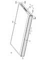
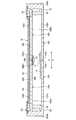
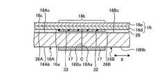
図1は、一実施形態に係る携帯用情報機器10を閉じて収納形態とした状態を示す斜視図である。図2は、図1に示す携帯用情報機器10を開いて使用形態とした状態を模式的に示す斜視図である。図3は、図2に示す携帯用情報機器10の内部構造を模式的に示す側面断面図である。 FIG. 1 is a perspective view showing a state in which the
図1及び図2に示すように、携帯用情報機器10は、第1筐体部材12A及び第2筐体部材12Bと、背表紙部材14と、ディスプレイ16とを備える。本実施形態の携帯用情報機器10は、本のように折り畳み可能なタブレット型PCである。携帯用情報機器10は、携帯電話、スマートフォン、電子手帳又は携帯用ゲーム機等であってもよい。 As shown in FIGS. 1 and 2, the
各筐体部材12A,12Bは、それぞれ背表紙部材14に対応する辺以外の3辺に側壁を起立形成した矩形の板状部材である。各筐体部材12A,12Bは、例えばステンレスやマグネシウム、アルミニウム等の金属板、或いは炭素繊維等の強化繊維を含む繊維強化樹脂板等で構成される。ディスプレイ16は、筐体部材12A,12Bの内面12Ac,12Bc間に亘るように設けられている。ディスプレイ16は、内面12Ac,12Bcに対して、第1支持プレート18A及び第2支持プレート18Bを介して支持されている。 Each of the
筐体部材12A,12Bは、互いに隣接して配置されている。筐体部材12A,12B間は、互いの隣接縁部である一縁部12Aa,12Baの両端部に設けられた一対のヒンジ機構19,19を介して連結されている。ヒンジ機構19は、筐体部材12A,12B間を図1に示す収納形態と図2に示す使用形態とに折り畳み可能に連結している。収納形態では、筐体部材12A,12Bが略同一平面上に配置される。使用形態では、筐体部材12A,12Bが互いに対面する位置まで折り畳まれる。図3中に1点鎖線で示す線Cは、筐体部材12A,12Bの折り畳み動作の中心となる折曲中心Cを示している。各筐体部材12A,12Bは、背表紙部材14側の一縁部12Aa,12Baがヒンジ側端部となる。各筐体部材12A,12Bは、背表紙部材14側とは反対側の他縁部12Ab,12Bbが開放端部となる。 The
ヒンジ機構19は、例えば各筐体部材12A,12Bの一縁部12Aa,12Baの長手方向(Y方向)両端部のそれぞれに配置され、ディスプレイ16の外周縁部の外側に位置している。本実施形態の携帯用情報機器10は、ヒンジ機構19による筐体部材12A,12B間の回動中心がディスプレイ16の表面16cと一致した構成となっている。 The
以下、図1及び図2に示すように、携帯用情報機器10について、中央の背表紙部材14から他縁部12Ab,12Bbに向かう方向をX方向、背表紙部材14の長手方向に沿う方向をY方向と呼んで説明する。 Hereinafter, as shown in FIGS. 1 and 2, with respect to the
ディスプレイ16は、例えばタッチパネル式の液晶ディスプレイである。ディスプレイ16は、例えば柔軟性の高いペーパー構造を持った有機EL等のフレキシブルディスプレイである。ディスプレイ16は、筐体部材12A,12Bの開閉動作に伴って開閉する。ディスプレイ16は、その表面16cの外周縁部にベゼル部材23が配設される。ベゼル部材23は、ディスプレイ16の表面の表示領域(アクティブ領域)R1を除く外周縁部の非表示領域(非アクティブ領域)R2を覆っている。 The
ディスプレイ16は、例えば最上層のタッチパネル部、上層の表示部、下層のシート状部材16d(図4A参照)、最下層のカバーフィルム部等を積層したアセンブリ部品である。図4A等では、ディスプレイ16の断面構造として、タッチパネル部及び表示部をまとめてパネル部16eとして図示し、シート状部材16dの下にあるカバーフィルム部の図示は省略している。カバーフィルム部は設けなくてもよい。 The
シート状部材16dは、ディスプレイ16を所望の折曲軌跡に沿って折曲動作させるための補助部材である。シート状部材16dは、ステンレスを圧延によって薄く形成したステンレス製のシートである。シート状部材16dは、圧延を受けることで磁化された磁性体(強磁性体)である。シート状部材16dは、ディスプレイ16の裏面16aの下方に配置された磁石17によって吸引可能である。本実施形態のシート状部材16dは、ディスプレイ16の全面に亘って延在している(図4A参照)。これにより、ディスプレイ16の厚みが不均一になることを容易に防止できる。但し、シート状部材16dは、少なくとも折曲領域16bに重なる位置に設けられていればよい。シート状部材16dの厚みは特に限定されないが、例えば数十μm、或いは100μm〜200μm程度である。シート状部材16dは、ディスプレイ16の折曲動作を適切に補助することができ、さらに磁性体で形成されていれば、ステンレス以外の金属材料で形成されてもよい。 The sheet-shaped
ディスプレイ16は、例えば図3に示すように支持プレート18A,18Bの外周端面に突設された取付片24を介して筐体部材12A,12Bに位置決め固定される。取付片24は、支持プレート18A,18Bの隣接する一縁部18Aa,18Ba以外の外周縁部の適宜箇所に複数設けられている。取付片24は、例えば内面12Ac,12Bcに設けられたボス部25に対してねじ止めされる。これにより各支持プレート18A,18Bは、それぞれ各筐体部材12A,12Bの内面12Ac,12Bcに取り付けられる。 As shown in FIG. 3, for example, the
各筐体部材12A,12Bと支持プレート18A,18Bとに挟まれた筐体内部空間には、基板、CPU等の各種半導体チップ、通信モジュール、バッテリ装置、冷却装置等の各種部品が取付固定されている。 Various semiconductor chips such as a substrate and a CPU, communication modules, battery devices, cooling devices, and other various parts are mounted and fixed in the housing internal space sandwiched between the
背表紙部材14は、可撓性を持った薄い板状部材で形成され、携帯用情報機器10を折り畳んだ際の背表紙となる。背表紙部材14は一縁部12Aa,12Ba間を内側から覆うように筐体部材12A,12Bの内面12Ac,12Bc間に亘って設けられている。図1に示すように、携帯用情報機器10は、収納形態では、筐体部材12A,12Bの一縁部12Aa,12Ba間が大きく離間して隙間を生じる。背表紙部材14は、この一縁部12Aa,12Ba間の隙間を覆うことで、内部のディスプレイ16や各種部品が露呈することを防止している。 The
図3に示すように、背表紙部材14は、例えば第1筐体部材12Aの内面12Acに対してはこれに沿ってX方向にスライド可能に設けられ、第2筐体部材12Bの内面12Bcに対してはねじ止め等によってスライド不能に固定されている。これにより背表紙部材14は、筐体部材12A,12B間の開閉動作に追従するようにスライドし、収納形態で一縁部12Aa,12Ba間の隙間を覆う。 As shown in FIG. 3, the
次に、支持プレート18A,18Bの構成例を説明する。図3に示すように、各支持プレート18A,18Bは、薄いプレート状部材である。支持プレート18A,18Bは、ディスプレイ16を支持するプレートである。ディスプレイ16は、その裏面16aが支持プレート18A,18Bの表面18Ac,18Bcに対して粘着部材26を用いて固定されている。各支持プレート18A,18Bは、それぞれ各筐体部材12A,12Bに支持され、折曲中心Cを中心として本のように開閉される。 Next, a configuration example of the
支持プレート18A,18Bは、例えばステンレス等の金属板、或いは炭素繊維等による繊維強化樹脂板等で構成される。支持プレート18A,18Bは、使用形態では、隣接する一縁部18Aa,18Ba同士が当接する(図4A参照)。支持プレート18A,18Bは、収納形態では、一縁部18Aa,18Ba同士が離間する(図4B参照)。 The
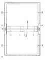
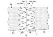
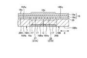
次に、磁石17の構成例を説明する。図4Aは、使用形態でのディスプレイ16、磁石17、粘着部材26及び支持プレート18A,18Bの構成を模式的に示す側面断面図である。図4Bは、収納形態でのディスプレイ16、磁石17、粘着部材26及び支持プレート18A,18Bの構成を模式的に示す側面断面図である。図5は、携帯用情報機器10の内部構造を模式的に示す平面図であり、図2に示す携帯用情報機器10からディスプレイ16及びベゼル部材23を省略した図である。 Next, a configuration example of the
磁石17は、磁性体であるシート状部材16dを吸引可能な永久磁石である。磁石17は、ディスプレイ16の折曲領域16bと重なる位置に配置されている。折曲領域16bは、筐体部材12A,12B間及び支持プレート18A,18B間が折り畳まれた際、ディスプレイ16が円弧状に湾曲する部分である(図4B参照)。図4A及び図4Bに示す構成例において、磁石17は、左右一対で構成され、支持プレート18A,18Bの裏面18Ab,18Bbにそれぞれ設けられている。各磁石17は、裏面18Ab,18Bbの一縁部18Aa,18Ba側端部に配置されている。磁石17に代えて、例えば図4A中の左右の磁石17,17をまとめて1つの磁石で構成したものを用いてもよい。この場合、この1つの磁石は、一方の支持プレート18A(18B)に固定され、他方の支持プレート18B(18A)まで亘る長さを有し、片持ち支持で配置されるとよい。 The
図4Aに示す使用形態において、各磁石17は、折曲領域16bの下方に配置され、折曲中心Cを挟んで互いに隣接する。この際、各磁石17は、シート状部材16dに対して最も近い位置に配置される。図4Bに示す収納形態において、各磁石17は、互いに離間した支持プレート18A,18Bに伴って互いに離間し、使用形態時よりもシート状部材16dから大きく離間した位置に配置される。 In the usage pattern shown in FIG. 4A, the
図5中に破線で示すように、磁石17は、例えば折曲領域16bに重なる範囲でY方向に沿って帯状に配置される。図5中に2点鎖線で示すように、磁石17は、折曲領域16bに重なる位置で、Y方向で両端部に配置されてもよい。この場合、磁石17は、さらにY方向で中央部にも配置されてもよい。 As shown by the broken line in FIG. 5, the
次に、粘着部材26の構成例を説明する。図6は、支持プレート18A,18Bの表面18Ac,18Bcに設けられた粘着部材26の一部を拡大した平面図である。 Next, a configuration example of the
図4A及び図4Bに示すように、粘着部材26は、ディスプレイ16の裏面16aと、支持プレート18A,18Bの表面18Ac,18Bcとの間を固定している。粘着部材26は、例えばPSA(Pressure Sensitive Adhesive)、OCA(Optical Clear Adhesive)等の両面テープである。粘着部材26の厚みは、例えば10μm〜30μm程度である。なお、粘着部材とは、2つの物質間を固定する部材を示すものであり、テープ状に形成された両面テープ以外、例えば塗布によって両面テープと同様に用いられる粘着剤等も含む概念である。 As shown in FIGS. 4A and 4B, the
図4A、図4B及び図6に示すように、粘着部材26は、第1粘着部26Aと、第2粘着部26Bと、弱粘着部27とを有する。 As shown in FIGS. 4A, 4B and 6, the
第1粘着部26Aは、第1支持プレート18Aの表面18Acと、これに重なるディスプレイ16の裏面16aの略半分の領域とを粘着する。第2粘着部26Bは、第2支持プレート18Bの表面18Bcと、これに重なるディスプレイ16の裏面16aの略半分の領域とを粘着する。第1粘着部26Aと第2粘着部26Bは、弱粘着部27を挟んで左右に設けられる。 The first
弱粘着部27は、折曲中心Cを跨ぐように設けられ、Y方向に沿って帯状に延在している。弱粘着部27は、粘着部26A,26Bよりも粘着力が弱い部分である。弱粘着部27は、少なくともディスプレイ16の折曲領域16bと重なる範囲に設けられている。弱粘着部27は、折曲領域16bよりも多少広い範囲に設けられてもよい。 The weak
弱粘着部27は、支持プレート18A,18B間の境界線(折曲中心C)を基準として、第1支持プレート18Aに粘着された第1領域27Aと、第2支持プレート18Bに粘着された第2領域27Bとを有する。領域27A,27Bは、ディスプレイ16の折曲領域16bに重なる位置に沿って並んだ複数の孔部28を有する。各孔部28は、粘着部材26が設けられていない円形の領域である。孔部28の形状は適宜変更可能である。 The weakly
図6に示す構成例では、孔部28は、折曲中心Cを基準として左右対称形状となっている。具体的には、孔部28は、X方向に円形の孔部28を5つ並べた構成であり、折曲中心Cに重なる中央の孔部28が最も大径となっている。この最も大径の孔部28は、そのX方向半分ずつを第1領域31Aと第2領域31Bとで利用している。この最も大径の孔部28は、Y方向で隣接する孔部28,28間の部分が切れ目29で左右に分断されている。つまり第1領域31Aと第2領域31Bとの間は、折曲中心Cに沿った切れ目29と孔部28によって分断されている。孔部28の形状や配置は適宜変更可能である。 In the configuration example shown in FIG. 6, the
弱粘着部27は、複数の孔部28を有することで、単位面積当たりで見た場合の粘着力が粘着部26A,26Bよりも弱い。換言すれば、粘着部26A,26Bは、孔部28を持たない分だけ、弱粘着部27よりも単位面積当たりの粘着力が強いとも言える。粘着部26A,26Bは、粘着部材26の使用量の低減のため、多少は粘着剤を設けない部分が存在していてもよいが、少なくとも弱粘着部27よりも単位面積当たりの粘着剤を設けていない部分の割合が小さい。弱粘着部27は、例えば孔部28の形状に形成した図示しないマスキングテープを貼り付けた支持プレート18A,18B上に粘着部材26を塗布し、マスキングテープに重なった部分の粘着部材26を他の部分から切りとるように、マスキングテープと共に剥がすことで、容易に形成できる。 Since the weak
本実施形態のディスプレイ16は、その裏面16aがシリコーン製のカバーフィルム部で形成されている。一方、支持プレート18A,18Bは、その表面18Ac,18Bcも含めて繊維強化樹脂板で形成されている。このため、上記したPSAやOCA等で形成された粘着部材26は、ディスプレイ16よりも支持プレート18A,18Bに対してより強力に粘着される。その結果、粘着部26A,26Bよりも粘着力の弱い弱粘着部27は、支持プレート18A,18Bに対してはある程度大きな粘着力で粘着される。一方、弱粘着部27は、ディスプレイ16に対しては小さな粘着力で粘着される。このため、弱粘着部27は、引き剥がし力を受けた場合、支持プレート18A,18Bよりもディスプレイ16から優先して剥がれる。 The
弱粘着部27の構成は、限定されない。弱粘着部27は、例えば図7に示すように、波形状を有する弱粘着部30としてもよい。弱粘着部30は、弱粘着部27と同様に第1領域27A及び第2領域27Bを有するが、その形状が異なる。すなわち、弱粘着部30の各領域27A,27Bは、折曲中心Cに沿って延びた波形状を有する。領域27A,27Bの波形状同士は、例えば0.5周期分だけ位相がずれた状態で隙間31を介して対向している。隙間31は、第1領域27Aと第2領域27Bとの間で粘着部材26が設けられていない領域である。従って、このような弱粘着部30においても、隙間31を有することで、単位面積当たりで見た場合の粘着力が粘着部26A,26Bよりも弱い。 The configuration of the weak
弱粘着部27,30は、その粘着面の一部をマスキングテープ等のマスキング材でカバーすることで一部の粘着面をカバーし、これにより粘着力を弱めた構成としてもよい。また、粘着部材26は、孔部28やマスキング材等を用いた構成に代えて、粘着部26A,26Bの部分よりも粘着性の低い粘着剤を用いることで弱粘着部を形成してもよい。さらに、粘着部材26は、粘着部26A,26B及び弱粘着部を全て同一の粘着剤で均等に形成しておき、ディスプレイ16の裏面16a又は支持プレート18A,18Bの表面18Ac,18Bcの折曲領域16bに対応する部分に粘着部材26と粘着力を低下させるコーティング等の表面処理を施すことで、弱粘着部を形成してもよい。 The weak
次に、携帯用情報機器10を使用形態から収納形態に折り畳む動作を説明する。 Next, the operation of folding the
携帯用情報機器10が図2に示す使用形態にある場合、図4Aに示すように、支持プレート18A,18Bは、互いの一縁部18Aa,18Baの端面同士が当接し、1枚の平板を形成している。この状態では、粘着部材26の粘着部26A,26Bは、支持プレート18A,18Bとディスプレイ16との間を広い面積で粘着している。粘着部材26の弱粘着部27(30)は、平板状の支持プレート18A,18Bの一縁部18Aa,18Baの周辺部と、その上で開かれて1枚の平板状に形成されたディスプレイ16の折曲領域16bとの間を粘着している。この際、磁石17は、シート状部材16dに対して最も近い位置に配置される。このため、ディスプレイの折曲領域16bは、磁石17の吸引力によって支持プレート18A,18B側へと引き寄せられ、表面18Ac,18Bcに対して押し付けられる(図4A中の矢印M参照)。つまり、この構成例の場合、支持プレート18A,18Bは、磁石17の磁力を透過できる素材である必要がある。 When the
この形態では、ディスプレイ16は、磁石17の磁力により、折曲領域16bも含めた略全面が支持プレート18A,18B上に確実に固定される。このため、ディスプレイ16は、折曲領域16b及びその周辺部も含めてしわや浮き上がりを生じることが抑制される。その結果、当該携帯用情報機器10は、使用形態時のディスプレイ16の外観品質や視認性が確保される。上記した通り、磁石17は、少なくともY方向で両端部付近に配置される。これにより、しわや浮き上がりが目立ち易い、ディスプレイ16の折曲領域16bのY方向両端部でのしわ等の発生をより確実に抑制できる。しかも粘着部材26は、折曲領域16bに重なる範囲に弱粘着部27(30)を備える。このため、弱粘着部27(30)の粘着作用により、ディスプレイ16の折曲領域16bがしわ等を生じることが一層確実に抑制される。換言すれば、この構成例では、粘着部材26が弱粘着部27等を備えため、磁石17による吸引作用を低く設定してもしわ等の発生を抑制できる。このため、磁石17を小型化、薄型化することができる。 In this embodiment, the magnetic force of the
次に、携帯用情報機器10を使用形態から収納形態に折り畳む場合、図4Bに示すように、粘着部材26の弱粘着部27がディスプレイ16の裏面16aから剥がれる。すなわち、粘着部材26は、ヒンジ機構19の回動中心であるディスプレイ16の表面16cよりも外側にあるため、折曲時の内輪差で引張方向の力を受ける。このため、折曲領域16bに対して配置され、他の部分(粘着部26A,26B)よりも粘着力が弱い弱粘着部27は、支持プレート18A,18Bの表面18Ac,18Bc又はディスプレイ16の裏面16aから引き剥がされる方向の力を受ける。この際、シリコーンで形成されたディスプレイ16の裏面16aに対する粘着力は、支持プレート18A,18Bの表面18Ac,18Bcに対する粘着力よりも相対的に弱い。このため、弱粘着部27はディスプレイ16から剥がれ、支持プレート18A,18B上に残る。 Next, when the
同時に、支持プレート18A,18Bは、その一縁部18Aa,18Ba間が離間する。その際、各磁石17は、離間した支持プレート18A,18Bに伴って互いに離間し、シート状部材16dから大きく離間した位置に配置される。このため、各磁石17は、収納形態時にはシート状部材16dを吸引しない。その結果、収納形態時には、弱粘着部27は、第1粘着部26A及び第1領域27Aが第1支持プレート18A上に残り、第2粘着部26B及び第2領域27Bが第2支持プレート18B上に残って状態となる(図4B参照)。また、この形態で磁石17の磁力がディスプレイ16に悪影響を及ぼすことも抑えられている。 At the same time, the
このように、当該携帯用情報機器10は、収納形態へと折り畳む際は弱粘着部27がディスプレイ16から剥がれ、同時に磁石17の吸引力も作用しなくなる。その結果、ディスプレイ16は、収納形態へと円滑に折り畳まれる。さらに、折り畳み時にディスプレイ16が過度な負荷や設計条件を越えた曲率での折曲力を受けることが抑制される。また、当該携帯用情報機器10は、使用形態時にディスプレイ16の折曲領域16bにしわや浮き上がりが形成されないことで、折り畳み動作の開始時に、このようなしわや浮き上がりが圧縮力を受けて、さらに浮き上がって座屈することによる不具合の発生も抑制できる。 As described above, when the
次に、携帯用情報機器10を収納形態から使用形態に開くと、弱粘着部27は、図5Aに示すようにディスプレイ16と支持プレート18A,18Bとの間で押圧され、再び、両者間を粘着する。同時に磁石17は、その吸引力によって折曲領域16bを支持プレート18A,18B側に引き寄せる。このため、ディスプレイ16は、折曲領域16bも含めた略全面が支持プレート18A,18B上に再び固定され、折曲領域16b及びその周辺部も含めてしわや浮き上がりを生じることが抑制される。 Next, when the
弱粘着部27(30)は、折り畳み時に支持プレート18A,18Bから剥がれ、ディスプレイ16に残る構成としてもよい。この場合、例えばディスプレイ16の裏面16a又は支持プレート18,18Bの表面18Ac,18Bcの素材を、図4A及び図4Bに示す構成例から変更すればよい。 The weak adhesive portion 27 (30) may be peeled off from the
磁石17は、使用形態時にディスプレイ16の折曲領域16bを支持プレート18A,18B側に吸引可能であれば、その形状や配置は適宜変更可能である。例えば図4Aでは、折曲領域16bを覆う範囲に磁石17を配置した構成を例示したが、磁石17は、折曲領域16bに重なる範囲の一部のみに配置されてもよい。磁石17は、支持プレート18A,18Bのうちの一方のみに配置されてもよい。 The shape and arrangement of the
磁石17は、図8に示すように、支持プレート18A,18Bの内部に埋設されてもよい。そうすると、磁石17が携帯用情報機器10の厚みに影響を及ぼすことがなく、当該携帯用情報機器10を一層薄型化することができる。また、磁石17が、裏面18Ab,18Bbから突出しないことで、その下方に配設する電子部品の設置自由度が向上する。 As shown in FIG. 8, the
磁石17は、図9に示すように、支持プレート18A,18Bの裏面18Ab,18Bbに形成した凹部に配置してもよい。これにより磁石17は、支持プレート18A,18Bの裏面18Ab,18Bb側に埋設される。磁石17は、図9中に2点鎖線で示すように、支持プレート18A,18Bの表面18Ac,18Bcに形成した凹部に埋設してもよい。このように磁石17を裏面18Ab,18Bb又は表面18Ac,18Bcに形成した凹部に配置することで、図8に示す構成例よりも磁石17の設置作業が容易となる。磁石17は、その一部のみが支持プレート18A,18Bに埋設されていてもよい。 As shown in FIG. 9, the
磁石17は、図3中に2点鎖線で示すように、背表紙部材14の表面に設けられていてもよい。背表紙部材14は、使用形態時に図3に示すように、折曲中心Cを覆うように配置されるため、この折曲中心Cを覆う部分に磁石17を設けるとよい。磁石17は、背表紙部材14に埋設してもよい。背表紙部材14を設けない構成等の場合、磁石17は、筐体部材12A,12Bの内面12Ac,12Bcに設けてもよい。 The
粘着部材26は、弱粘着部27(30)に代えて、折曲領域16bに重なる範囲の粘着面の一面又は両面の粘着力をなくした構成としてもよい。例えば図10に示す非粘着部32は、粘着部材26の一面にマスキングテープ等の樹脂フィルムを設けた構成である。つまり上記弱粘着部27(30)は、その一部に非粘着部29(31)を設けることで、寝着剤の粘着力を弱めた構成となっていた。これに対し、非粘着部32は、折曲領域16bに重なる部分で粘着剤の一面を樹脂フィルム等で覆うことで、粘着力を持たない構成となっている。非粘着部32は、例えば折曲中心Cを挟んで左右一対設けられ、第1粘着部26A側と第2粘着部26B側とに分割されている。各非粘着部32は、使用形態時にはディスプレイ16の裏面16aに当接し、収納形態時には裏面16aから離間する。このような非粘着部32を設けた構成においても、図8に示す使用形態時には、磁石17の吸引力によってディスプレイ16の折曲領域16bが支持プレート18A,18B側へと引き寄せられる。その結果、ディスプレイ16は、折曲領域16b及びその周辺部も含めてしわや浮き上がりを生じることが抑制される。 Instead of the weak adhesive portion 27 (30), the
粘着部材26は、図11に示すように、弱粘着部27(30)や非粘着部32に代えて、折曲領域16bに重なる範囲に粘着剤を設けない構成としてもよい。図11に示す粘着部材26は、第1粘着部26A及び第2粘着部26Bと、粘着部26A,26B間で粘着剤の設置されない領域(非粘着部34)とを有する。このような非粘着部34を設けた構成においても、図9に示す使用形態時には、磁石17の吸引力によってディスプレイ16の折曲領域16bが支持プレート18A,18B側へと引き寄せられる。その結果、ディスプレイ16は、折曲領域16b及びその周辺部も含めてしわや浮き上がりを生じることが抑制される。なお、図10や図11に示す構成例の場合、粘着部材26は、折曲領域16bに重なる範囲においてもディスプレイ16の裏面16a等に対して剥離や再粘着が可能である必要がない。このため、この場合の粘着部材26は、再粘着を必要としない接着剤によって形成してもよい。 As shown in FIG. 11, the
なお、本発明は、上記した実施形態に限定されるものではなく、本発明の主旨を逸脱しない範囲で自由に変更できることは勿論である。 It should be noted that the present invention is not limited to the above-described embodiment, and of course, it can be freely changed without departing from the gist of the present invention.
上記では、本のように二つ折りに折り畳み可能な携帯用情報機器10を例示したが、本発明は、同形の筐体部材同士を二つ折りに折り畳む構成以外、例えば大形の筐体部材の左右縁部にそれぞれ小形の筐体部材を折り畳み可能に連結した観音開きの構成、1つの筐体部材の左右縁部にそれぞれ折り畳み方向の異なる筐体部材を連結したS型の折り畳み構成、大形の筐体部材の左右一方の縁部に小形の筐体部材を折り畳み可能に連結したJ型の折り畳み構成等、各種構成に適用可能であり、筐体部材の連結数は4以上としてもよい。 In the above, the
10 携帯用情報機器
12A 第1筐体部材
12B 第2筐体部材
14 背表紙部材
16 ディスプレイ
16b 折曲領域
16d シート状部材
17 磁石
18A 第1支持プレート
18B 第2支持プレート
26 粘着部材
27,30 弱粘着部
28 孔部
31 隙間
32,34 非粘着部
10
Claims (7)
Translated fromJapanese第1筐体部材と、
前記第1筐体部材に対して相対的に回動可能に連結された第2筐体部材と、
前記第1筐体部材に固定された第1支持プレートと、
前記第2筐体部材に固定され、前記第1支持プレートと隣接して設けられた第2支持プレートと、
前記第1支持プレート及び前記第2支持プレートの表面で、その裏面が支持され、前記第1筐体部材と前記第2筐体部材が相対的に回動することに応じて折り曲げられる折曲領域を有するディスプレイと、
前記第1支持プレート及び前記第2支持プレートの表面と、前記ディスプレイの裏面とを粘着により固定する粘着部材と、
を備え、
少なくとも前記折曲領域と重なる範囲において、前記第1支持プレート及び前記第2支持プレートの表面と、前記ディスプレイの裏面との間の粘着力を他の部分よりも弱めた弱粘着部、又は、前記第1支持プレート及び前記第2支持プレートの表面と、前記ディスプレイの裏面とのうち、少なくとも一方の面に対して粘着しない非粘着部を有し、
前記ディスプレイは、少なくとも前記折曲領域と重なる位置に磁性体を有し、
さらに、前記折曲領域と重なる位置で前記ディスプレイの裏面よりも下方に設けられ、前記磁性体を吸引可能な磁石を備え、
前記磁石は、前記第1支持プレート及び前記第2支持プレートのうち、少なくとも一方の裏面に配置されていることを特徴とする携帯用情報機器。It is a portable information device
With the first housing member
The second housing member, which is rotatably connected to the first housing member,
The first support plate fixed to the first housing member and
A second support plate fixed to the second housing member and provided adjacent to the first support plate,
A bent region in which the back surface of the first support plate and the front surface of the second support plate is supported, and the first housing member and the second housing member are bent in response to relative rotation. With a display that has
An adhesive member that adhesively fixes the front surface of the first support plate and the second support plate to the back surface of the display.
With
A weak adhesive portion having a weaker adhesive force between the front surface of the first support plate and the second support plate and the back surface of the display than other portions, or the weak adhesive portion, at least in a range overlapping the bent region. It has a non-adhesive portion that does not adhere to at least one of the front surface of the first support plate and the second support plate and the back surface of the display.
The display has a magnetic material at least at a position overlapping the bent region.
Further, a magnet provided below the back surface of the display at a position overlapping the bent region and capable of attracting the magnetic material is provided.
The magnet, the one of the first support plate and the second support plate, a portable information equipment which is characterized that youhave arranged in at least one of the back surface.
前記磁石は、前記第1筐体部材と前記第2筐体部材との間をそれぞれが略同一平面上にある使用形態とした場合に、前記磁性体を吸引し、前記ディスプレイを前記第1支持プレート及び前記第2支持プレート側へと引き寄せ、
前記磁石は、前記第1筐体部材と前記第2筐体部材との間をそれぞれが対面する位置まで折り畳んで前記ディスプレイが折り曲げられた収納形態とした場合には、前記使用形態の場合よりも前記磁性体から離間した位置に配置されることを特徴とする携帯用情報機器。The portable information device according to claim 1.
The magnet attracts the magnetic material and supports the display by the first support when the first housing member and the second housing member are used in substantially the same plane. Pull toward the plate and the second support plate side,
When the magnet is folded to a position where the first housing member and the second housing member face each other to form a storage form in which the display is bent, the magnet is more than in the case of the usage form. A portable information device characterized in that it is arranged at a position away from the magnetic material.
第1筐体部材と、
前記第1筐体部材に対して相対的に回動可能に連結された第2筐体部材と、
前記第1筐体部材に固定された第1支持プレートと、
前記第2筐体部材に固定され、前記第1支持プレートと隣接して設けられた第2支持プレートと、
前記第1支持プレート及び前記第2支持プレートの表面で、その裏面が支持され、前記第1筐体部材と前記第2筐体部材が相対的に回動することに応じて折り曲げられる折曲領域を有するディスプレイと、
前記第1支持プレート及び前記第2支持プレートの表面と、前記ディスプレイの裏面とを粘着により固定する粘着部材と、
を備え、
少なくとも前記折曲領域と重なる範囲において、前記第1支持プレート及び前記第2支持プレートの表面と、前記ディスプレイの裏面との間の粘着力を他の部分よりも弱めた弱粘着部、又は、前記第1支持プレート及び前記第2支持プレートの表面と、前記ディスプレイの裏面とのうち、少なくとも一方の面に対して粘着しない非粘着部を有し、
前記ディスプレイは、少なくとも前記折曲領域と重なる位置に磁性体を有し、
さらに、前記折曲領域と重なる位置で前記ディスプレイの裏面よりも下方に設けられ、前記磁性体を吸引可能な磁石を備え、
前記磁石は、前記第1筐体部材と前記第2筐体部材との間をそれぞれが略同一平面上にある使用形態とした場合に、前記磁性体を吸引し、前記ディスプレイを前記第1支持プレート及び前記第2支持プレート側へと引き寄せ、
前記磁石は、前記第1筐体部材と前記第2筐体部材との間をそれぞれが対面する位置まで折り畳んで前記ディスプレイが折り曲げられた収納形態とした場合には、前記使用形態の場合よりも前記磁性体から離間した位置に配置されるものであり、
さらに、前記収納形態において、前記第1筐体部材及び前記第2筐体部材の隣接する一縁部間に形成される隙間を覆うように、前記第1筐体部材の内面と前記第2筐体部材の内面との間に亘って設けられた背表紙部材を備え、
前記背表紙部材は、前記第1筐体部材の内面に対しては該内面に沿って前記第2筐体部材から前記第1筐体部材に向かう方向にスライド可能に設けられ、前記第2筐体部材の内面に対してはスライド不能に固定されており、
前記磁石は、前記背表紙部材に設けられていることを特徴とする携帯用情報機器。It is a portable information device
With the first housing member
The second housing member, which is rotatably connected to the first housing member,
The first support plate fixed to the first housing member and
A second support plate fixed to the second housing member and provided adjacent to the first support plate,
A bent region in which the back surface of the first support plate and the front surface of the second support plate is supported, and the first housing member and the second housing member are bent in response to relative rotation. With a display that has
An adhesive member that adhesively fixes the front surface of the first support plate and the second support plate to the back surface of the display.
With
A weak adhesive portion having a weaker adhesive force between the front surface of the first support plate and the second support plate and the back surface of the display than other portions, or the weak adhesive portion, at least in a range overlapping the bent region. It has a non-adhesive portion that does not adhere to at least one of the front surface of the first support plate and the second support plate and the back surface of the display.
The display has a magnetic material at least at a position overlapping the bent region.
Further, a magnet provided below the back surface of the display at a position overlapping the bent region and capable of attracting the magnetic material is provided.
The magnet attracts the magnetic material and supports the display by the first support when the first housing member and the second housing member are used in substantially the same plane. Pull toward the plate and the second support plate side,
When the magnet is folded to a position where the first housing member and the second housing member face each other to form a storage form in which the display is bent, the magnet is more than in the case of the usage form. It is arranged at a position away from the magnetic material, and is arranged.
Further, in the storage form, the inner surface of the first housing member and the second housing so as to cover the gap formed between the first housing member and the adjacent edge portion of the second housing member. It is provided with a spine cover member provided between the inner surface of the body member.
The spine member is provided so as to be slidable with respect to the inner surface of the first housing member in a direction from the second housing member toward the first housing member along the inner surface, and the second housing is provided. It is fixed to the inner surface of the body member so that it cannot slide.
The magnet is a portable information device provided on the spine member.
前記磁性体は、圧延された金属製のシート状部材であることを特徴とする携帯用情報機器。The portable information device according to any one of claims 1 to3.
The magnetic material is a portable information device characterized by being a rolled metal sheet-like member.
前記シート状部材は、ステンレス製であることを特徴とする携帯用情報機器。The portable information device according to claim4.
The sheet-shaped member is a portable information device made of stainless steel.
前記シート状部材は、前記ディスプレイの全面に亘って延在していることを特徴とする携帯用情報機器。The portable information device according to claim4 or5.
The sheet-shaped member is a portable information device that extends over the entire surface of the display.
前記磁石は、前記折曲領域の長手方向で少なくとも両端部に近接した位置に配置されていることを特徴とする携帯用情報機器。The portable information device according to any one of claims 1 to6.
A portable information device characterized in that the magnet is arranged at a position close to at least both ends in the longitudinal direction of the bent region.
Priority Applications (2)
| Application Number | Priority Date | Filing Date | Title |
|---|---|---|---|
| JP2019154929AJP6837106B2 (en) | 2019-08-27 | 2019-08-27 | Portable information equipment |
| US16/749,734US10831234B1 (en) | 2019-08-27 | 2020-01-22 | Portable information device |
Applications Claiming Priority (1)
| Application Number | Priority Date | Filing Date | Title |
|---|---|---|---|
| JP2019154929AJP6837106B2 (en) | 2019-08-27 | 2019-08-27 | Portable information equipment |
Publications (2)
| Publication Number | Publication Date |
|---|---|
| JP2021033778A JP2021033778A (en) | 2021-03-01 |
| JP6837106B2true JP6837106B2 (en) | 2021-03-03 |
Family
ID=73052082
Family Applications (1)
| Application Number | Title | Priority Date | Filing Date |
|---|---|---|---|
| JP2019154929AActiveJP6837106B2 (en) | 2019-08-27 | 2019-08-27 | Portable information equipment |
Country Status (2)
| Country | Link |
|---|---|
| US (1) | US10831234B1 (en) |
| JP (1) | JP6837106B2 (en) |
Families Citing this family (9)
| Publication number | Priority date | Publication date | Assignee | Title |
|---|---|---|---|---|
| KR102705836B1 (en)* | 2019-02-26 | 2024-09-12 | 삼성디스플레이 주식회사 | Display apparatus |
| CN110827691B (en)* | 2019-11-27 | 2021-11-23 | 武汉华星光电半导体显示技术有限公司 | Display panel support frame and display device |
| KR20210096725A (en)* | 2020-01-28 | 2021-08-06 | 삼성디스플레이 주식회사 | Foldable display device |
| WO2022162933A1 (en)* | 2021-02-01 | 2022-08-04 | シャープディスプレイテクノロジー株式会社 | Display device |
| TWI811972B (en)* | 2021-04-23 | 2023-08-11 | 元太科技工業股份有限公司 | Flexible display device |
| US12277004B2 (en)* | 2021-06-11 | 2025-04-15 | Samsung Electronics Co., Ltd. | Hinge apparatus and electronic device including the same |
| CN114464089B (en)* | 2022-01-12 | 2023-07-25 | 武汉华星光电半导体显示技术有限公司 | Folding display panel and display device |
| JP7361823B2 (en)* | 2022-03-16 | 2023-10-16 | レノボ・シンガポール・プライベート・リミテッド | Electronics |
| WO2025004176A1 (en)* | 2023-06-27 | 2025-01-02 | シャープディスプレイテクノロジー株式会社 | Display device |
Family Cites Families (20)
| Publication number | Priority date | Publication date | Assignee | Title |
|---|---|---|---|---|
| EP2388687A4 (en)* | 2009-01-19 | 2013-07-24 | Si Hwan Kim | Portable display device |
| US8971032B2 (en)* | 2012-11-02 | 2015-03-03 | Blackberry Limited | Support for a flexible display |
| US9013864B2 (en)* | 2012-11-02 | 2015-04-21 | Blackberry Limited | Support for a flexible display |
| KR102333557B1 (en)* | 2014-12-30 | 2021-12-01 | 엘지디스플레이 주식회사 | Foldable display apparatus |
| KR102272355B1 (en)* | 2015-01-19 | 2021-07-05 | 삼성디스플레이 주식회사 | Display apparatus |
| KR102344282B1 (en)* | 2015-03-17 | 2021-12-30 | 삼성디스플레이 주식회사 | Display device |
| KR102542197B1 (en)* | 2016-10-19 | 2023-06-13 | 삼성디스플레이 주식회사 | Flexible Display Device |
| US10416710B2 (en)* | 2017-01-10 | 2019-09-17 | Lenovo (Singapore) Pte. Ltd. | Portable information device |
| JP6507183B2 (en)* | 2017-01-10 | 2019-04-24 | レノボ・シンガポール・プライベート・リミテッド | Portable information equipment |
| US10409332B2 (en)* | 2017-01-10 | 2019-09-10 | Lenovo (Singapore) Pte. Ltd. | Portable information device |
| US10481634B2 (en)* | 2017-01-10 | 2019-11-19 | Lenovo (Singapore) Pte. Ltd. | Portable information device |
| JP6429909B2 (en)* | 2017-01-10 | 2018-11-28 | レノボ・シンガポール・プライベート・リミテッド | Portable information equipment |
| JP6535353B2 (en) | 2017-01-10 | 2019-06-26 | レノボ・シンガポール・プライベート・リミテッド | Portable information equipment |
| JP6513732B2 (en)* | 2017-04-27 | 2019-05-15 | レノボ・シンガポール・プライベート・リミテッド | Portable information equipment |
| CN108953864B (en)* | 2017-05-23 | 2021-02-19 | 元太科技工业股份有限公司 | Bearing device and display |
| JP6453413B1 (en)* | 2017-10-04 | 2019-01-16 | レノボ・シンガポール・プライベート・リミテッド | Portable information equipment |
| KR102454248B1 (en)* | 2018-03-29 | 2022-10-17 | 삼성디스플레이 주식회사 | Display apparatus |
| KR102452238B1 (en)* | 2018-05-11 | 2022-10-07 | 삼성디스플레이 주식회사 | Display device |
| KR102549716B1 (en)* | 2018-07-16 | 2023-07-03 | 삼성디스플레이 주식회사 | Display apparatus |
| JP2020046541A (en)* | 2018-09-19 | 2020-03-26 | レノボ・シンガポール・プライベート・リミテッド | Portable information appliance |
- 2019
- 2019-08-27JPJP2019154929Apatent/JP6837106B2/enactiveActive
- 2020
- 2020-01-22USUS16/749,734patent/US10831234B1/enactiveActive
Also Published As
| Publication number | Publication date |
|---|---|
| JP2021033778A (en) | 2021-03-01 |
| US10831234B1 (en) | 2020-11-10 |
Similar Documents
| Publication | Publication Date | Title |
|---|---|---|
| JP6837106B2 (en) | Portable information equipment | |
| JP6898485B1 (en) | Portable information equipment and display assembly | |
| JP6758442B2 (en) | Portable information equipment | |
| JP6828105B1 (en) | Portable information equipment | |
| CN112068636B (en) | Portable information device and display assembly | |
| JP6715359B1 (en) | Portable information device and method for manufacturing the portable information device | |
| US10908639B2 (en) | Portable information device | |
| JP2019067279A (en) | Portable information equipment | |
| US20220149337A1 (en) | Method for manufacturing a display device | |
| US11307612B2 (en) | Portable information device and cover device | |
| JP6952833B1 (en) | Portable information equipment | |
| JP2007529776A (en) | Electronic panel device that can be rolled | |
| US20220137669A1 (en) | Portable information device and double-sided adhesive tape | |
| US20200323086A1 (en) | Hinge for electronic device, and electronic device | |
| JP2021071752A (en) | Portable information device and manufacturing method thereof | |
| JP2021033776A (en) | Portable information device | |
| JP2018112836A (en) | Portable information apparatus and method for manufacturing support plate | |
| JP2024053677A (en) | Tape member and electronic device | |
| JP7561927B1 (en) | Electronics and Display Assembly | |
| JP7366207B1 (en) | Electronics | |
| JP2021043492A (en) | Electronic device |
Legal Events
| Date | Code | Title | Description |
|---|---|---|---|
| A621 | Written request for application examination | Free format text:JAPANESE INTERMEDIATE CODE: A621 Effective date:20190827 | |
| A131 | Notification of reasons for refusal | Free format text:JAPANESE INTERMEDIATE CODE: A131 Effective date:20201027 | |
| A521 | Request for written amendment filed | Free format text:JAPANESE INTERMEDIATE CODE: A523 Effective date:20210118 | |
| TRDD | Decision of grant or rejection written | ||
| A01 | Written decision to grant a patent or to grant a registration (utility model) | Free format text:JAPANESE INTERMEDIATE CODE: A01 Effective date:20210202 | |
| A61 | First payment of annual fees (during grant procedure) | Free format text:JAPANESE INTERMEDIATE CODE: A61 Effective date:20210208 | |
| R150 | Certificate of patent or registration of utility model | Ref document number:6837106 Country of ref document:JP Free format text:JAPANESE INTERMEDIATE CODE: R150 | |
| S111 | Request for change of ownership or part of ownership | Free format text:JAPANESE INTERMEDIATE CODE: R313113 | |
| R350 | Written notification of registration of transfer | Free format text:JAPANESE INTERMEDIATE CODE: R350 | |
| R250 | Receipt of annual fees | Free format text:JAPANESE INTERMEDIATE CODE: R250 | |
| R250 | Receipt of annual fees | Free format text:JAPANESE INTERMEDIATE CODE: R250 | |
| S111 | Request for change of ownership or part of ownership | Free format text:JAPANESE INTERMEDIATE CODE: R313113 | |
| R350 | Written notification of registration of transfer | Free format text:JAPANESE INTERMEDIATE CODE: R350 |