JP6836194B2 - Camera cleaning device for vehicle rear door - Google Patents
Camera cleaning device for vehicle rear doorDownload PDFInfo
- Publication number
- JP6836194B2 JP6836194B2JP2017198200AJP2017198200AJP6836194B2JP 6836194 B2JP6836194 B2JP 6836194B2JP 2017198200 AJP2017198200 AJP 2017198200AJP 2017198200 AJP2017198200 AJP 2017198200AJP 6836194 B2JP6836194 B2JP 6836194B2
- Authority
- JP
- Japan
- Prior art keywords
- camera
- injection nozzle
- lens
- garnish
- rear door
- Prior art date
- Legal status (The legal status is an assumption and is not a legal conclusion. Google has not performed a legal analysis and makes no representation as to the accuracy of the status listed.)
- Active
Links
Images


Classifications
- B—PERFORMING OPERATIONS; TRANSPORTING
- B60—VEHICLES IN GENERAL
- B60S—SERVICING, CLEANING, REPAIRING, SUPPORTING, LIFTING, OR MANOEUVRING OF VEHICLES, NOT OTHERWISE PROVIDED FOR
- B60S1/00—Cleaning of vehicles
- B60S1/02—Cleaning windscreens, windows or optical devices
- B60S1/56—Cleaning windscreens, windows or optical devices specially adapted for cleaning other parts or devices than front windows or windscreens
- H—ELECTRICITY
- H04—ELECTRIC COMMUNICATION TECHNIQUE
- H04N—PICTORIAL COMMUNICATION, e.g. TELEVISION
- H04N23/00—Cameras or camera modules comprising electronic image sensors; Control thereof
- H04N23/50—Constructional details
- B—PERFORMING OPERATIONS; TRANSPORTING
- B08—CLEANING
- B08B—CLEANING IN GENERAL; PREVENTION OF FOULING IN GENERAL
- B08B3/00—Cleaning by methods involving the use or presence of liquid or steam
- B08B3/02—Cleaning by the force of jets or sprays
- B—PERFORMING OPERATIONS; TRANSPORTING
- B08—CLEANING
- B08B—CLEANING IN GENERAL; PREVENTION OF FOULING IN GENERAL
- B08B3/00—Cleaning by methods involving the use or presence of liquid or steam
- B08B3/04—Cleaning involving contact with liquid
- B—PERFORMING OPERATIONS; TRANSPORTING
- B60—VEHICLES IN GENERAL
- B60R—VEHICLES, VEHICLE FITTINGS, OR VEHICLE PARTS, NOT OTHERWISE PROVIDED FOR
- B60R13/00—Elements for body-finishing, identifying, or decorating; Arrangements or adaptations for advertising purposes
- B60R13/04—External Ornamental or guard strips; Ornamental inscriptive devices thereon
- B—PERFORMING OPERATIONS; TRANSPORTING
- B60—VEHICLES IN GENERAL
- B60S—SERVICING, CLEANING, REPAIRING, SUPPORTING, LIFTING, OR MANOEUVRING OF VEHICLES, NOT OTHERWISE PROVIDED FOR
- B60S1/00—Cleaning of vehicles
- B—PERFORMING OPERATIONS; TRANSPORTING
- B60—VEHICLES IN GENERAL
- B60S—SERVICING, CLEANING, REPAIRING, SUPPORTING, LIFTING, OR MANOEUVRING OF VEHICLES, NOT OTHERWISE PROVIDED FOR
- B60S1/00—Cleaning of vehicles
- B60S1/02—Cleaning windscreens, windows or optical devices
- B60S1/46—Cleaning windscreens, windows or optical devices using liquid; Windscreen washers
- B60S1/48—Liquid supply therefor
- B60S1/52—Arrangement of nozzles; Liquid spreading means
- G—PHYSICS
- G02—OPTICS
- G02B—OPTICAL ELEMENTS, SYSTEMS OR APPARATUS
- G02B27/00—Optical systems or apparatus not provided for by any of the groups G02B1/00 - G02B26/00, G02B30/00
- G02B27/0006—Optical systems or apparatus not provided for by any of the groups G02B1/00 - G02B26/00, G02B30/00 with means to keep optical surfaces clean, e.g. by preventing or removing dirt, stains, contamination, condensation
Landscapes
- Engineering & Computer Science (AREA)
- Mechanical Engineering (AREA)
- Physics & Mathematics (AREA)
- Water Supply & Treatment (AREA)
- General Physics & Mathematics (AREA)
- Optics & Photonics (AREA)
- Multimedia (AREA)
- Signal Processing (AREA)
- Studio Devices (AREA)
- Camera Bodies And Camera Details Or Accessories (AREA)
- Cleaning By Liquid Or Steam (AREA)
Description
Translated fromJapanese本発明は、車両のリアドアに設けられたカメラのレンズを洗浄するための車両リアドア用カメラ洗浄装置に関する。 The present invention relates to a camera cleaning device for a vehicle rear door for cleaning a camera lens provided on a vehicle rear door.
特許文献1は車両リアドア用カメラ洗浄装置を開示している。即ち、特許文献1に開示された車両のリアドア(バックドア)のアウタパネルにはカメラが固定されている。カメラは、リアドアに固定されたカメラケースと、カメラケースに支持され且つカメラケースの後面において露出するレンズと、カメラケースと一体化し且つカメラケースの後面において開口する噴射ノズルと、を備えている。 Patent Document 1 discloses a camera cleaning device for a vehicle rear door. That is, the camera is fixed to the outer panel of the rear door (back door) of the vehicle disclosed in Patent Document 1. The camera includes a camera case fixed to a rear door, a lens supported by the camera case and exposed on the rear surface of the camera case, and an injection nozzle integrated with the camera case and opened on the rear surface of the camera case.
リアドアの後方に位置する被写体によって反射された撮影光束がレンズに入射すると、例えば車内に設けられたディスプレイに被写体が表示される。 When the shooting light flux reflected by the subject located behind the rear door is incident on the lens, the subject is displayed on a display provided in the vehicle, for example.
カメラケースの内部には、一端が噴射ノズルに接続され且つ他端がポンプを介して洗浄水用タンクに接続された洗浄水用流路が形成されている。例えばレンズの表面に異物が付着したときにポンプが作動すると、洗浄水タンク内の洗浄水が高圧化されながら洗浄水用流路を介して噴射ノズルに供給される。すると、高圧の洗浄水が噴射ノズルから外部に噴射される。その結果、噴射された洗浄水の一部がカメラのレンズに向かうので、洗浄水によってレンズから異物が除去される。 Inside the camera case, a washing water flow path is formed, one end of which is connected to an injection nozzle and the other end of which is connected to a washing water tank via a pump. For example, when the pump operates when a foreign substance adheres to the surface of the lens, the washing water in the washing water tank is supplied to the injection nozzle through the washing water flow path while increasing the pressure. Then, high-pressure washing water is ejected from the injection nozzle to the outside. As a result, a part of the sprayed cleaning water goes to the lens of the camera, and the cleaning water removes foreign matter from the lens.
しかしながら特許文献1では、洗浄水が噴射ノズルから拡散されながら噴射される。即ち、噴射ノズルは、洗浄水の噴射方向を精度よく制御できない。そのため、噴射ノズルから噴射された洗浄水の一部のみがレンズに向かう。換言すると、噴射された洗浄水の残部は、例えば車両のレンズとは異なる部位に向けて噴射される。そのため、特許文献1では洗浄水が有効に利用されていない。 However, in Patent Document 1, the washing water is sprayed while being diffused from the jet nozzle. That is, the injection nozzle cannot accurately control the injection direction of the washing water. Therefore, only a part of the cleaning water ejected from the injection nozzle goes toward the lens. In other words, the balance of the sprayed wash water is sprayed toward a portion different from the lens of the vehicle, for example. Therefore, in Patent Document 1, the washing water is not effectively used.
さらに噴射ノズルはアウタパネルの外面(後面)において後方に露出している。そのため噴射ノズルによってリアドアの美観が損なわれていた。 Further, the injection nozzle is exposed rearward on the outer surface (rear surface) of the outer panel. Therefore, the appearance of the rear door was spoiled by the injection nozzle.
本発明は上述した課題に対処するためになされたものである。即ち、本発明の目的の一つは、噴射ノズルから噴射された洗浄水によってカメラのレンズを効率よく洗浄でき、且つ、噴射ノズルによってリアドアの美観が損なわれることを防止できる車両リアドア用カメラ洗浄装置を提供することにある。 The present invention has been made to address the above-mentioned problems. That is, one of the objects of the present invention is a camera cleaning device for a vehicle rear door that can efficiently clean the camera lens with the cleaning water ejected from the injection nozzle and prevent the injection nozzle from spoiling the aesthetic appearance of the rear door. Is to provide.
本発明の車両リアドア用カメラ洗浄装置は、
車両(10)の後方に位置する被写体を撮像可能なカメラ(25、55)が固定され且つ前記車両のリアドア(13)の外面を構成するアウタパネル(15)に、前記カメラのレンズ(27)より上方に位置するように固定された、前記レンズに向けて洗浄水を拡散させながら噴射可能な噴射ノズル(30、56)と、
前記アウタパネルの後方に位置するように前記アウタパネルに固定されたガーニッシュ(20)と、
を備え、
前記アウタパネルと前記ガーニッシュとの間に前記噴射ノズルが配設される。The camera cleaning device for a vehicle rear door of the present invention
A camera (25, 55) capable of capturing an image of a subject located behind the vehicle (10) is fixed to an outer panel (15) constituting the outer surface of the rear door (13) of the vehicle from the lens (27) of the camera. Injection nozzles (30, 56) that are fixed so as to be located above and can be ejected while diffusing the washing water toward the lens.
A garnish (20) fixed to the outer panel so as to be located behind the outer panel,
With
The injection nozzle is arranged between the outer panel and the garnish.
本発明の車両リアドア用カメラ洗浄装置によれば、洗浄水が噴射ノズルから拡散されながら噴射されると、噴射された洗浄水の一部はレンズに直接到達する。さらに、噴射された洗浄水の残部の一部は、ガーニッシュによって反射された後にレンズに到達する。そのため、洗浄水が拡散されながら噴射ノズルから噴射されるにも拘わらず、噴射された洗浄水全体に対するレンズに到達する洗浄水の割合が高くなる。換言すると、噴射ノズルから噴射された洗浄水によってカメラのレンズを効率よく洗浄できる。 According to the vehicle rear door camera cleaning device of the present invention, when the cleaning water is sprayed while being diffused from the injection nozzle, a part of the sprayed cleaning water reaches the lens directly. In addition, some of the remnants of the sprayed wash water reach the lens after being reflected by the garnish. Therefore, although the cleaning water is sprayed from the injection nozzle while being diffused, the ratio of the cleaning water reaching the lens to the entire sprayed cleaning water is high. In other words, the camera lens can be efficiently cleaned by the cleaning water ejected from the injection nozzle.
さらに本発明の車両リアドア用カメラ洗浄装置によれば、噴射ノズルの後方への露出がガーニッシュによって防止される。そのため、噴射ノズルによってリアドアの美観が損なわれることが防止される。 Further, according to the vehicle rear door camera cleaning device of the present invention, the rear exposure of the injection nozzle is prevented by the garnish. Therefore, it is possible to prevent the rear door from being spoiled by the injection nozzle.
本発明装置の一態様において、前記ガーニッシュの下端部(21)の前面が前記噴射ノズルと対向し且つ前記下端部を下方に延長した仮想延長線(IL)上に前記レンズが位置するように前記ガーニッシュの形状が設定される。 In one aspect of the apparatus of the present invention, the lens is located on a virtual extension line (IL) in which the front surface of the lower end portion (21) of the garnish faces the injection nozzle and the lower end portion extends downward. The shape of the garnish is set.
本発明をこの態様で実施すると、噴射ノズルから噴射され且つガーニッシュの下端部の内面に当たった洗浄水がレンズに到達し易くなる。そのため、噴射ノズルから噴射された洗浄水によってカメラのレンズをより効率よく洗浄できる。 When the present invention is carried out in this embodiment, the cleaning water ejected from the injection nozzle and hitting the inner surface of the lower end portion of the garnish easily reaches the lens. Therefore, the camera lens can be washed more efficiently with the washing water jetted from the jet nozzle.
上記説明においては、本発明の理解を助けるために、後述する実施形態に対応する発明の構成に対し、その実施形態で用いた名称及び/又は符号を括弧書きで添えている。しかしながら、本発明の各構成要素は、前記符号によって規定される実施形態に限定されるものではない。本発明の他の目的、他の特徴及び付随する利点は、以下の図面を参照しつつ記述される本発明の実施形態についての説明から容易に理解されるであろう。 In the above description, in order to help the understanding of the present invention, the names and / or symbols used in the embodiments are added in parentheses to the configurations of the invention corresponding to the embodiments described later. However, each component of the present invention is not limited to the embodiment defined by the reference numerals. Other objects, other features and accompanying advantages of the invention will be readily understood from the description of embodiments of the invention described with reference to the drawings below.
以下、本発明の実施形態に係るリアドア用カメラ洗浄装置について添付図面を参照しながら説明する。 Hereinafter, the rear door camera cleaning device according to the embodiment of the present invention will be described with reference to the accompanying drawings.
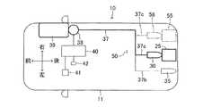
図1及び図2に示す車両10は、車体11と、4つの車輪12(図1に左右の後輪のみ図示)と、を備えている。車体11の背面には背面開口部11aが形成されている。背面開口部11aにはリアドア13(バックドア)が設けられている。 The
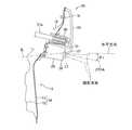
リアドア13は、リアドア13の下半部を構成する本体部14と、リアドア13の上半部を構成するドアサッシュ17と、本体部14とドアサッシュ17との間に形成された開口部に設けられたリアウィンド18と、を備えている。さらに図3乃至図5に示すように本体部14は、その車外側部(後部)を構成する金属製のアウタパネル15と、アウタパネル15の直前に位置する金属製のインナパネル16と、を有している。図3に示すように、アウタパネル15とインナパネル16の一部同士はボルト19によって固定されている。さらに図1及び図3乃至図5に示すように、アウタパネル15の外面(後面)には車幅方向(左右方向)に延びるガーニッシュ20の上縁部が固定されている。ガーニッシュ20の上縁部を除く部位とアウタパネル15との間には空間が形成されている。ガーニッシュ20の下端部21は、側面視において上下方向に対して傾斜するように加工されている。さらにガーニッシュ20がボルト19の直後に位置しているので、ボルト19の後方への露出がガーニッシュ20によって防止されている。さらに図1に示すように、アウタパネル15には、ワイパー22の基端部が回転可能に支持されている。 The
図1乃至図5に示すように、アウタパネル15の外面にはリアカメラ25が固定されている。リアカメラ25は、アウタパネル15に固定されたカメラケース26と、カメラケース26の後端部に固定されたレンズ27と、カメラケース26に内蔵された撮像素子(図示略)と、を備えている。図3に示すように、車両10(リアドア13)の後方に位置する被写体(図示略)によって反射された撮影光束がレンズ27に入射すると、レンズ27を透過した撮影光束が撮像素子によって受光される。すると撮像素子が撮像データを画像処理装置(図示略)に送信し、画像処理装置が撮像データを画像処理する。この画像処理装置は、図2に示す制御装置40を介して、インストルメントパネル(図示略)に固定されたディスプレイ41に接続されている。そのため、画像処理装置によって画像処理された被写体を表す画像がディスプレイ41に表示される。即ち、リアカメラ25は電子インナーミラーとして利用される。換言すると、リアカメラ25は電子インナーミラー用のカメラとして適している。なお、図3に示すように、レンズ27の光軸27OAと水平方向とがなす角度θ1は比較的小さい(換言すると、後述するリアカメラ55の光軸と水平方向とがなす角度より小さい)。即ち、リアカメラ25は、リアドア13の後方の風景(例えば、道路)、並びにリアドア13の後方に位置する人物及び物等を撮影する。 As shown in FIGS. 1 to 5, the
図3乃至図5に示すように、リアカメラ25の直後にはガーニッシュ20が位置し、且つ、ガーニッシュ20の下端部21がレンズ27の上部と前後方向に対向する。しかし、リアカメラ25のレンズ27に入射する撮影光束の断面形状はレンズ27の画角によって規定され、且つ、図3に示すようにガーニッシュ20の下端部21は撮影光束より上方に位置する。そのため、ガーニッシュ20(下端部21)がディスプレイ41に表示されることはない。
さらに側面視において、下端部21を下方(前方)に延長した仮想延長線IL上にレンズ27が位置する。As shown in FIGS. 3 to 5, the
Further, in the side view, the
図1乃至図5に示すようにアウタパネル15の外面にはカメラ用噴射ノズル30が固定されている。図3乃至図5に示すように、カメラ用噴射ノズル30の下面の後端部には噴射口31が形成されている。カメラ用噴射ノズル30はリアカメラ25の直上に位置する。即ち、カメラ用噴射ノズル30の噴射口31は、リアカメラ25のレンズ27より上方に位置する。
さらにカメラ用噴射ノズル30の直後にガーニッシュ20が位置し、且つ、噴射口31と下端部21とが微小隙間を形成しながら対向する。そのためカメラ用噴射ノズル30の後方への露出がガーニッシュ20によって防止される。そのためカメラ用噴射ノズル30によってリアドア13(及び車両10)の美観が損なわれることがない。As shown in FIGS. 1 to 5, a
Further, the
図2乃至図5に示すように、カメラ用噴射ノズル30には第1分岐チューブ37aの一端が接続されている。第1分岐チューブ37aは図2に示す送水用チューブ37の一部であり、送水用チューブ37の第1分岐チューブ37aと反対側の端部は電動ポンプ38を介して洗浄水タンク39に接続されている。洗浄水タンク39には洗浄水が充填されている。さらに制御装置40には、インストルメントパネルに固定された洗浄スイッチ42が接続されている。 As shown in FIGS. 2 to 5, one end of the
さらに図1及び図2に示すように、ドアサッシュ17の外面の上部にはウィンド用噴射ノズル35が固定されている。ウィンド用噴射ノズル35の下面には噴射口36が形成されており、噴射口36はリアウィンド18の外面と対向している。図2に示すように、ウィンド用噴射ノズル35には第2分岐チューブ37bの一端が接続されている。第2分岐チューブ37bは送水用チューブ37の一部である。 Further, as shown in FIGS. 1 and 2, a
本実施形態では、ガーニッシュ20、カメラ用噴射ノズル30、送水用チューブ37、電動ポンプ38、洗浄水タンク39、制御装置40、及び洗浄スイッチ42がカメラ洗浄装置50の構成要素である。 In the present embodiment, the
例えば、リアウィンド18又はレンズ27の表面に異物が付着したときに、車両10の車内にいる乗員が手で洗浄スイッチ42を押すと、それまでOFF位置に位置していた洗浄スイッチ42がON位置に移動する。すると洗浄スイッチ42がON位置に位置する間、制御装置40が電動ポンプ38に対して作動信号(電気信号)を送信し続ける。作動信号を受けた電動ポンプ38は洗浄水タンク39内の洗浄水に圧力を与えて、洗浄水タンク39内の洗浄水を送水用チューブ37側へ送る。すると、洗浄水タンク39から送水用チューブ37へ流れた洗浄水が、第1分岐チューブ37a及び第2分岐チューブ37bにそれぞれ流れる。そのため、カメラ用噴射ノズル30の噴射口31及びウィンド用噴射ノズル35の噴射口36から洗浄水がそれぞれ拡散しながら噴射される。 For example, when a foreign object adheres to the surface of the
ウィンド用噴射ノズル35の噴射口36から噴射された洗浄水はリアウィンド18の外面に付着する。洗浄水がリアウィンド18の外面に付着した状態で、ワイパー用モータ(図示略)の動力を利用してワイパー22を回転させると、ワイパー22によってリアウィンド18の外面に付着していた異物が除去される。 The cleaning water injected from the
一方、カメラ用噴射ノズル30の噴射口31から噴射された洗浄水は、図4に示すように拡散されながら下方へ向かう。すると噴射された高圧の洗浄水の一部W1はレンズ27に直接到達する。さらに噴射された高圧の洗浄水の残部の一部W2は、ガーニッシュ20の下端部21の内面によって反射される。上述したように、下端部21を下方(前方)に延長した仮想延長線IL上にレンズ27が位置するので、ガーニッシュ20の下端部21によって反射された洗浄水W2はレンズ27に到達する。従って、これらの高圧の洗浄水W1、W2によってレンズ27の表面から異物が除去される。
さらに図5に示すように、下端部21の内面(前面)とカメラ用噴射ノズル30の噴射口31との間の空間に洗浄水の一部W3が一時的に溜まる。この洗浄水W3はある程度の水圧を有している。洗浄水W3は、下端部21の内面に沿ってレンズ27へ向かい且つレンズ27の表面の異物を除去しながらレンズ27の下方へ落下する。On the other hand, the cleaning water ejected from the
Further, as shown in FIG. 5, a part of the cleaning water W3 temporarily collects in the space between the inner surface (front surface) of the
このように洗浄水W1のみならず、洗浄水W2及び洗浄水W3によっても、レンズ27から異物が除去される。即ち、洗浄水が拡散されながらカメラ用噴射ノズル30の噴射口31から噴射されるにも拘わらず、噴射された洗浄水全体に対するレンズ27に到達する洗浄水の割合が高くなる。換言すると、カメラ用噴射ノズル30から噴射された洗浄水によってレンズ27の表面の異物が効率よく洗浄される。 In this way, foreign matter is removed from the
乗員が手を洗浄スイッチ42から離すと、洗浄スイッチ42は自動的にOFF位置に復帰する。すると制御装置40が電動ポンプ38に対して作動信号の送信を停止するので電動ポンプ38が停止する。そのため、洗浄水はカメラ用噴射ノズル30及びウィンド用噴射ノズル35から噴射されなくなる。 When the occupant releases his / her hand from the cleaning
以上、本発明を上記実施形態に基づいて説明したが、本発明は上記実施形態に限定されるものではなく、本発明の目的を逸脱しない限りにおいて種々の変更が可能である。 Although the present invention has been described above based on the above embodiment, the present invention is not limited to the above embodiment, and various modifications can be made without departing from the object of the present invention.
例えば、図1及び図2に仮想線で示す示すように、アウタパネル15の外面に、リアカメラ25とは異なるリアカメラ55及びリアカメラ55の直上に位置するカメラ用噴射ノズル56を固定してもよい。この変形例では、ガーニッシュ20、カメラ用噴射ノズル30、送水用チューブ37、電動ポンプ38、洗浄水タンク39、制御装置40、洗浄スイッチ42、及びカメラ用噴射ノズル56がカメラ洗浄装置50の構成要素である。 For example, as shown by virtual lines in FIGS. 1 and 2, even if the
このリアカメラ55の構造はリアカメラ25と同一であり且つリアカメラ55は前記画像処理装置に接続されている。但し、リアカメラ55のレンズの光軸と水平方向とがなく角度はθ1より大きい。そのため、リアカメラ55は、例えば、リアドア13から短距離離れた領域(例えば、リアドア13から1m乃至2m離れた領域)の地面(路面)を撮影する。そして、リアカメラ55が撮影した画像はディスプレイ41に表示される。即ち、リアカメラ55は駐車用バックカメラとして利用される。換言すると、リアカメラ55は駐車用バックカメラ用のカメラとして適している。なお、リアカメラ55のレンズとしては、例えば広角レンズ又は魚眼レンズを利用可能である。さらにリアカメラ55の直後にはガーニッシュ20が位置し、且つ、ガーニッシュ20の下端部21がリアカメラ55のレンズの上部と前後方向に対向する。但し、リアカメラ55のレンズに入射する撮影光束より上方にガーニッシュ20の下端部21が位置する。 The structure of the
カメラ用噴射ノズル56の構造はカメラ用噴射ノズル30と同一である。そしてカメラ用噴射ノズル56には、送水用チューブ37の一部である第3分岐チューブ37cの一端が接続されている。カメラ用噴射ノズル56の直後にガーニッシュ20が位置し、且つ、カメラ用噴射ノズル56の噴射口と下端部21とが微小隙間を形成しながら対向する。そのためカメラ用噴射ノズル56の後方への露出がガーニッシュ20によって防止される。そのためカメラ用噴射ノズル56によってリアドア13(及び車両10)の美観が損なわれることがない。 The structure of the
そしてこの変形例では、カメラ用噴射ノズル56から噴射される洗浄水によって、リアカメラ55のレンズに付着した異物が効率よく洗浄される。 In this modified example, the cleaning water ejected from the
また、カメラ洗浄装置が、リアカメラ25のレンズ27及び/又はリアカメラ55のレンズに異物が付着したときにこの異物を検出する検出手段を備え、且つ、検出手段が異物を検出したときに電動ポンプ38を自動的に動作させてもよい。この変形例によれば、リアカメラ25のレンズ27及び/又はリアカメラ55のレンズに異物が付着したときに、リアカメラ25のレンズ27及び/又はリアカメラ55のレンズに付着した異物が洗浄水によって自動的に除去される。 Further, the camera cleaning device includes a detecting means for detecting the foreign matter when the foreign matter adheres to the
例えば、送水用チューブ37上に切換え弁を設けることにより、第1分岐チューブ37a、第2分岐チューブ37b、及び第3分岐チューブ37cのそれぞれに洗浄水を選択的に送水できるようにしてもよい。 For example, by providing a switching valve on the
さらにリアカメラ25とカメラ用噴射ノズル30とを一体化してもよい。
同様に、リアカメラ55とカメラ用噴射ノズル56とを一体化してもよい。Further, the
Similarly, the
リアカメラ25とリアカメラ55の一方のみをリアドア13に設けてもよい。 Only one of the
さらに、リアカメラ25の機能及びリアカメラ55の機能を備える1つのカメラをリアドア13に設けてもよい。このカメラはレンズの画角(焦点距離)を調整可能である。そのため、このカメラの画角(焦点距離)を調整することにより、このカメラはリアカメラ25が撮影可能な範囲に位置する被写体及びリアカメラ55が撮影可能な範囲に位置する被写体を選択的に撮影できる。 Further, one camera having the functions of the
リアカメラ25、リアカメラ55、及び/又は(リアカメラ25の機能及びリアカメラ55の機能を備える)上記カメラのレンズに入射する撮影光束が、ガーニッシュ20の一部によって反射された反射光を含んでいてもよい。但し、この場合は、画像処理装置が、撮像データを処理することにより、ディスプレイ41にガーニッシュ20が表示されないようにするのが好ましい。 The
さらにカメラ用噴射ノズル30が、圧縮空気をカメラ用噴射ノズル30の外部に噴射するためのエア噴射口を備えてもよい。このようにすれば、カメラ用噴射ノズル30から噴射された洗浄水がレンズ27の表面上に残留したときに、この残留した洗浄水を圧縮空気によって除去できる。
同様に、カメラ用噴射ノズル56が、圧縮空気をカメラ用噴射ノズル56の外部に噴射するためのエア噴射口を備えてもよい。このようにすれば、カメラ用噴射ノズル56から噴射された洗浄水がリアカメラ55のレンズの表面上に残留したときに、この残留した洗浄水を圧縮空気によって除去できる。Further, the
Similarly, the
13・・・リアドア、15・・・アウタパネル、20・・・ガーニッシュ、21・・・下端部、25・・・リアカメラ、26・・・カメラケース、27・・・レンズ、30・・・カメラ用噴射ノズル、35・・・ウィンド用噴射ノズル、39・・・洗浄水タンク、40・・・制御装置、41・・・ディスプレイ、42・・・洗浄スイッチ、50・・・カメラ洗浄装置、55・・・リアカメラ、56・・・カメラ用噴射ノズル。 13 ... rear door, 15 ... outer panel, 20 ... garnish, 21 ... lower end, 25 ... rear camera, 26 ... camera case, 27 ... lens, 30 ... camera Injection nozzle for 35 ... Wind injection nozzle, 39 ... Cleaning water tank, 40 ... Control device, 41 ... Display, 42 ... Cleaning switch, 50 ... Camera cleaning device, 55 ... rear camera, 56 ... injection nozzle for camera.
Claims (3)
Translated fromJapanese前記アウタパネルの後方に位置するように前記アウタパネルに固定されたガーニッシュと、
を備え、
前記アウタパネルと前記ガーニッシュとの間に前記噴射ノズルが配設され、
前記ガーニッシュの下端部の前面が前記噴射ノズルと対向し且つ前記下端部を下方且つ前記車両の前方に延長した仮想延長線上に前記レンズが位置するように前記ガーニッシュの形状が設定され、
前記噴射ノズルと前記ガーニッシュとが、前記噴射ノズルの前記噴射口から噴射された洗浄水の一部が前記レンズに直接到達するとともに、前記噴射ノズルの前記噴射口から噴射された洗浄水の残部の一部が前記ガーニッシュによって反射された後にレンズに到達するように構成された、
車両リアドア用カメラ洗浄装置。The outer panel an object located behind the vehicle captured camera capable constituting the rear door of the outer surface of the fixed and the vehicle,is fixed so as to be positioned above the lens of thecamera, pre-Symbol lensfrom the injection port With an injection nozzle that can inject while diffusing the washing water toward
A garnish fixed to the outer panel so as to be located behind the outer panel,
With
The injection nozzle is arranged between the outer panel and the garnish.
The shape of the garnish is set so that the front surface of the lower end portion of the garnish faces the injection nozzle and the lens is located on a virtual extension line extending the lower end portion downward and in front of the vehicle.
In the injection nozzle and the garnish, a part of the cleaning water ejected from the injection port of the injection nozzle reaches the lens directly, and the rest of the cleaning water ejected from the injection port of the injection nozzle. Partially configured to reach the lens after being reflected by the garnish,
Car both rear door for the camera cleaning equipment.
前記ガーニッシュの下端部が前記レンズの上部と前後方向において対向するように構成されている、
車両リアドア用カメラ洗浄装置。In the camera cleaning device for a vehicle rear door according to claim 1.
The lower end of the garnish is configured to face the upper part of the lens in the front-rear direction.
Car both rear door for the camera cleaning equipment.
前記噴射ノズル及び前記ガーニッシュは、 The injection nozzle and the garnish
前記ガーニッシュの下端部の前面と前記噴射ノズルの前記噴射口との間の空間に、前記噴射口から噴射された洗浄水の残部の他の一部が一時的に溜まり、前記空間に一時的に留まった洗浄水が前記レンズへ向かうように構成されている、 In the space between the front surface of the lower end portion of the garnish and the injection port of the injection nozzle, another part of the remaining part of the washing water sprayed from the injection port temporarily collects in the space temporarily. It is configured so that the retained wash water goes toward the lens.
車両リアドア用カメラ洗浄装置。 Camera cleaning device for vehicle rear doors.
Priority Applications (4)
| Application Number | Priority Date | Filing Date | Title |
|---|---|---|---|
| JP2017198200AJP6836194B2 (en) | 2017-10-12 | 2017-10-12 | Camera cleaning device for vehicle rear door |
| EP18178291.3AEP3470278B1 (en) | 2017-10-12 | 2018-06-18 | Vehicle |
| US16/012,232US10661762B2 (en) | 2017-10-12 | 2018-06-19 | Camera cleaning device |
| CN201810706837.6ACN109660702B (en) | 2017-10-12 | 2018-07-02 | camera cleaning device |
Applications Claiming Priority (1)
| Application Number | Priority Date | Filing Date | Title |
|---|---|---|---|
| JP2017198200AJP6836194B2 (en) | 2017-10-12 | 2017-10-12 | Camera cleaning device for vehicle rear door |
Publications (2)
| Publication Number | Publication Date |
|---|---|
| JP2019073043A JP2019073043A (en) | 2019-05-16 |
| JP6836194B2true JP6836194B2 (en) | 2021-02-24 |
Family
ID=62705499
Family Applications (1)
| Application Number | Title | Priority Date | Filing Date |
|---|---|---|---|
| JP2017198200AActiveJP6836194B2 (en) | 2017-10-12 | 2017-10-12 | Camera cleaning device for vehicle rear door |
Country Status (4)
| Country | Link |
|---|---|
| US (1) | US10661762B2 (en) |
| EP (1) | EP3470278B1 (en) |
| JP (1) | JP6836194B2 (en) |
| CN (1) | CN109660702B (en) |
Families Citing this family (10)
| Publication number | Priority date | Publication date | Assignee | Title |
|---|---|---|---|---|
| JP7356410B2 (en)* | 2018-03-07 | 2023-10-04 | 株式会社小糸製作所 | Sensor system with cleaner for vehicles |
| US11279325B2 (en)* | 2019-06-24 | 2022-03-22 | Ford Global Technologies, Llc | Sensor cleaning |
| DE102019209381A1 (en)* | 2019-06-27 | 2020-12-31 | Robert Bosch Gmbh | Device for protecting a sensor window |
| JP7188361B2 (en)* | 2019-11-15 | 2022-12-13 | トヨタ自動車株式会社 | vehicle front structure |
| CN112383682B (en)* | 2020-10-28 | 2022-03-22 | 安徽华铭达科技有限公司 | Panoramic camera |
| CN112702573B8 (en)* | 2020-12-23 | 2022-11-15 | 广西安正智能科技有限公司 | Monitoring equipment with automatic protective glass cleaning function |
| CN113928223A (en)* | 2021-10-28 | 2022-01-14 | 新乡北方车辆仪表有限公司 | A design method of self-adaptive cleaning photoelectric observation mirror for special vehicles |
| CN114809801B (en)* | 2022-05-11 | 2024-08-27 | 中核建创新科技有限公司 | Civil engineering safety management system and management monitoring method thereof |
| CN114951069B (en)* | 2022-06-05 | 2023-04-07 | 杨晓东 | Rock engineering ground hole measuring equipment and using method thereof |
| CN116890002A (en)* | 2023-07-11 | 2023-10-17 | 河南三鹰实业有限公司 | Security protection camera mounting structure |
Family Cites Families (10)
| Publication number | Priority date | Publication date | Assignee | Title |
|---|---|---|---|---|
| JP2010195360A (en)* | 2009-02-27 | 2010-09-09 | Daikyonishikawa Corp | Vehicular washer nozzle |
| US20110292212A1 (en)* | 2010-05-27 | 2011-12-01 | Asmo Co., Ltd. | Washer nozzle for vehicle mounted camera, vehicle mounted camera, and washer device for vehicle |
| JP5643157B2 (en)* | 2011-06-23 | 2014-12-17 | アスモ株式会社 | In-vehicle camera washer nozzle and in-vehicle camera cleaning system |
| JP5494743B2 (en) | 2011-10-14 | 2014-05-21 | 株式会社デンソー | Camera cleaning device |
| US20130146577A1 (en)* | 2011-12-08 | 2013-06-13 | Continental Automotive Systems, Inc. | Vehicle mounted optical and sensor cleaning system |
| RU2582478C1 (en)* | 2012-07-27 | 2016-04-27 | Ниссан Мотор Ко., Лтд. | Vehicle-mounted camera device |
| JP6536167B2 (en)* | 2015-05-20 | 2019-07-03 | 株式会社デンソー | In-vehicle optical sensor mounting bracket and in-vehicle optical sensor unit |
| US10604122B2 (en)* | 2015-06-30 | 2020-03-31 | Koito Manufacturing Co., Ltd. | Foreign matter removal device and vehicle provided with same |
| JP2017092752A (en)* | 2015-11-12 | 2017-05-25 | トヨタ自動車株式会社 | Imaging system |
| CN105872343A (en)* | 2016-06-29 | 2016-08-17 | 胡振强 | Vibrational self-dedusting monitor |
- 2017
- 2017-10-12JPJP2017198200Apatent/JP6836194B2/enactiveActive
- 2018
- 2018-06-18EPEP18178291.3Apatent/EP3470278B1/enactiveActive
- 2018-06-19USUS16/012,232patent/US10661762B2/enactiveActive
- 2018-07-02CNCN201810706837.6Apatent/CN109660702B/enactiveActive
Also Published As
| Publication number | Publication date |
|---|---|
| JP2019073043A (en) | 2019-05-16 |
| US20190111895A1 (en) | 2019-04-18 |
| US10661762B2 (en) | 2020-05-26 |
| EP3470278B1 (en) | 2020-11-04 |
| CN109660702B (en) | 2020-12-15 |
| CN109660702A (en) | 2019-04-19 |
| EP3470278A1 (en) | 2019-04-17 |
Similar Documents
| Publication | Publication Date | Title |
|---|---|---|
| JP6836194B2 (en) | Camera cleaning device for vehicle rear door | |
| US12036957B2 (en) | Vehicular cleaner system, vehicle having vehicular cleaner system, vehicular cleaner and vehicle having vehicular cleaner | |
| JP5803831B2 (en) | In-vehicle optical sensor cleaning device | |
| JP6998328B2 (en) | Vehicles with vehicle cleaner system and vehicle cleaner system | |
| JP6645984B2 (en) | Integrated cleaning assembly for image sensor support and lens | |
| JP7021590B2 (en) | Transmission / reception device for vehicles | |
| CN111032451B (en) | License plate lamp unit and vehicle with license plate lamp unit | |
| CN106660525A (en) | Integrated automotive system, compact, low-profile nozzle assembly and compact fluidic circuit for cleaning a wide-angle image sensor's exterior surface | |
| JP2013154771A (en) | On-vehicle camera device | |
| JP2011245989A (en) | Washer nozzle for on-vehicle camera, on-vehicle camera, and washer device for vehicle | |
| JP2004182080A (en) | Vehicle with infrared camera and infrared camera system | |
| JP2012201122A (en) | Nozzle device for vehicle-mounted camera, vehicle-mounted camera with cleaning device, and cleaning system for vehicle-mounted camera | |
| JP6822349B2 (en) | In-vehicle sensor cleaning device | |
| JP7125849B2 (en) | vehicle system | |
| CN112154083B (en) | Exterior mirror device for vehicle, exterior mirror system for vehicle, and method for controlling exterior mirror device for vehicle | |
| JP2020152338A (en) | Sensor cleaning device | |
| JP2019147449A (en) | Vehicle camera unit with cleaning function | |
| JP7356410B2 (en) | Sensor system with cleaner for vehicles | |
| JP2008147936A (en) | Optical component cleaning unit and in-camera cleaning system |
Legal Events
| Date | Code | Title | Description |
|---|---|---|---|
| A621 | Written request for application examination | Free format text:JAPANESE INTERMEDIATE CODE: A621 Effective date:20200219 | |
| A977 | Report on retrieval | Free format text:JAPANESE INTERMEDIATE CODE: A971007 Effective date:20201111 | |
| A131 | Notification of reasons for refusal | Free format text:JAPANESE INTERMEDIATE CODE: A131 Effective date:20201117 | |
| A521 | Request for written amendment filed | Free format text:JAPANESE INTERMEDIATE CODE: A523 Effective date:20201224 | |
| TRDD | Decision of grant or rejection written | ||
| A01 | Written decision to grant a patent or to grant a registration (utility model) | Free format text:JAPANESE INTERMEDIATE CODE: A01 Effective date:20210106 | |
| A61 | First payment of annual fees (during grant procedure) | Free format text:JAPANESE INTERMEDIATE CODE: A61 Effective date:20210119 | |
| R151 | Written notification of patent or utility model registration | Ref document number:6836194 Country of ref document:JP Free format text:JAPANESE INTERMEDIATE CODE: R151 |