JP6834808B2 - Display device and input control method - Google Patents
Display device and input control methodDownload PDFInfo
- Publication number
- JP6834808B2 JP6834808B2JP2017124988AJP2017124988AJP6834808B2JP 6834808 B2JP6834808 B2JP 6834808B2JP 2017124988 AJP2017124988 AJP 2017124988AJP 2017124988 AJP2017124988 AJP 2017124988AJP 6834808 B2JP6834808 B2JP 6834808B2
- Authority
- JP
- Japan
- Prior art keywords
- input
- area
- display
- region
- external device
- Prior art date
- Legal status (The legal status is an assumption and is not a legal conclusion. Google has not performed a legal analysis and makes no representation as to the accuracy of the status listed.)
- Expired - Fee Related
Links
Images


Landscapes
- User Interface Of Digital Computer (AREA)
Description
Translated fromJapanese本発明は、表示装置及び入力制御方法に関する。 The present invention relates to a display device and an input control method.
特許文献1に記載された画像表示装置は、画像を表示する表示部と、表示部の表示画面上に配置されたタッチ検出部と、外部装置(例えば、キーボード)を接続可能なIF部とを備える。表示部とタッチ検出部とはタッチパネルディスプレーを構成する。 The image display device described in Patent Document 1 includes a display unit for displaying an image, a touch detection unit arranged on the display screen of the display unit, and an IF unit to which an external device (for example, a keyboard) can be connected. Be prepared. The display unit and the touch detection unit constitute a touch panel display.
画像表示装置は、IF部に外部装置が接続されたことを検出すると、タッチ検出部の上にタッチ無効領域を確保する。タッチ無効領域は、外部装置を載置するための領域である。そして、タッチ無効領域では、タッチ操作が無効にされる。その結果、ユーザーは、外部装置を画像表示装置に接続し、外部装置をタッチパネルディスプレー上に置いて操作することができる。 When the image display device detects that an external device is connected to the IF unit, it secures a touch invalid area on the touch detection unit. The touch invalid area is an area for mounting an external device. Then, in the touch invalid area, the touch operation is invalidated. As a result, the user can connect the external device to the image display device and place the external device on the touch panel display for operation.
しかしながら、特許文献1に記載された画像表示装置では、外部装置の接続が検出されると、常にタッチ無効領域が確保される。一方、ユーザーは、外部装置を画像表示装置に接続した場合でも、外部装置をタッチパネルディスプレー上に置いて操作するとは限らない。従って、ユーザーの外部装置の使用状況によっては、タッチ無効領域は、タッチ有効領域を狭くしているだけであり、タッチパネルディスプレーの操作性を低下させる。 However, in the image display device described in Patent Document 1, when the connection of the external device is detected, the touch invalid area is always secured. On the other hand, even when the external device is connected to the image display device, the user does not always operate the external device by placing it on the touch panel display. Therefore, depending on the usage status of the external device of the user, the touch invalid area only narrows the touch effective area, which deteriorates the operability of the touch panel display.
本発明は、上記課題に鑑みてなされたものであり、外部装置が接続されたときに、タッチパネルディスプレーの操作性の低下を抑制できる表示装置及び入力制御方法を提供することを目的としている。 The present invention has been made in view of the above problems, and an object of the present invention is to provide a display device and an input control method capable of suppressing a decrease in operability of a touch panel display when an external device is connected.
本発明の一局面点によれば、表示装置は、外部装置を接続可能である。表示装置は、表示部と、タッチ検出部と、入力決定部とを備える。表示部は、画像を表示する。タッチ検出部は、前記表示部の表示面に対するタッチ入力を検出する。入力決定部は、前記外部装置が接続された後の前記表示面に対するタッチ入力に基づいて、前記表示面上の領域のうちの第1領域に対するタッチ入力を、有効な入力として処理するか、無効な入力として処理するかを決定する。 According to one aspect of the present invention, the display device can be connected to an external device. The display device includes a display unit, a touch detection unit, and an input determination unit. The display unit displays an image. The touch detection unit detects a touch input to the display surface of the display unit. The input determination unit processes or invalidates the touch input for the first area of the area on the display surface as a valid input based on the touch input for the display surface after the external device is connected. Decide whether to process as input.
本発明の他の局面によれば、入力制御方法は、外部装置を接続可能な表示装置によって実行される。入力制御方法は、前記外部装置が接続された後に、前記表示装置の表示面に対するタッチ入力が検出されたか否かを判定するステップと、前記表示面に対する前記タッチ入力が検出されと判定されたときに、前記タッチ入力に基づいて、前記表示面上の領域のうちの第1領域に対するタッチ入力を、有効な入力として処理するか、無効な入力として処理するかを決定するステップとを含む。 According to another aspect of the invention, the input control method is performed by a display device to which an external device can be connected. The input control method includes a step of determining whether or not a touch input to the display surface of the display device is detected after the external device is connected, and when it is determined that the touch input to the display surface is detected. Including a step of determining whether to process the touch input for the first area of the area on the display surface as a valid input or an invalid input based on the touch input.
本発明によれば、外部装置が接続されたときに、タッチパネルディスプレーの操作性の低下を抑制できる。 According to the present invention, it is possible to suppress a decrease in operability of the touch panel display when an external device is connected.
以下、本発明の実施形態について、図面を参照しながら説明する。なお、図中、同一または相当部分については同一の参照符号を付して説明を繰り返さない。 Hereinafter, embodiments of the present invention will be described with reference to the drawings. In the drawings, the same or corresponding parts are designated by the same reference numerals and the description is not repeated.
(実施形態1)
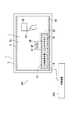
図1〜図7を参照して、本発明の実施形態1に係る表示システム100について説明する。まず、図1を参照して、表示システム100を説明する。図1は、表示システム100を示す図である。図1に示すように、表示システム100は、表示装置1と、外部装置200とを備える。表示装置1は画像IMを表示する。画像IMは、例えば、ボタンa1、ボタンa2、ボタンa3、及びボタンa4を含む。表示装置1は、外部装置200を接続可能である。外部装置200は、表示装置1に接続可能な機器である。外部装置200は、例えば、入力装置である。入力装置は、例えば、マウスのようなポインティングデバイス、又は、キーボードである。ただし、外部装置200は、電子機器である限りは、入力装置に限定されない。(Embodiment 1)
The
表示装置1は、タッチパネルディスプレー3と、接続ポート9(接続部)とを備える。接続ポート9に外部装置200が接続される。タッチパネルディスプレーは、タッチ入力を検出するとともに、画像IMを表示する。タッチ入力は、例えば、ユーザーの指FGによるタッチ入力である。 The display device 1 includes a
タッチパネルディスプレー3は、表示部5と、タッチ検出部7とを含む。表示部5は画像IMを表示する。表示部5は、例えば、液晶ディスプレー又は有機EL(Electro−Luminescence)ディスプレーである。 The
タッチ検出部7は、表示部5の表示面5aに対するタッチ入力を検出する。具体的には、タッチ検出部7は、表示部5の表示面5aに対するタッチ位置を検出し、タッチ位置を示すタッチ信号を出力する。タッチ位置は、例えば、ユーザーの指FGによるタッチ位置である。タッチ検出部7は表示部5に設置される。タッチ検出部7は、例えば、タッチパネルである。タッチパネルは、表示部5の表示面5aに設置されていてもよいし、オンセル型であってもよいし、インセル型であってもよい。また、タッチパネルの方式は、例えば、抵抗膜方式、又は、静電容量方式である。 The
表示装置1は、表示部5の表示面5aが水平方向に略平行になるように設置される。ただし、表示部5の表示面5aが水平方向に対して傾斜していてもよい。 The display device 1 is installed so that the
表示装置1は、タッチ入力に関するノーマルモードと入力制御モードとを有する。ユーザーは、タッチパネルディスプレー3又は外部装置200を介して、ノーマルモードと入力制御モードとを切り替える。 The display device 1 has a normal mode for touch input and an input control mode. The user switches between the normal mode and the input control mode via the
ノーマルモードは、表示部5の表示面5aの全領域に対して、常に、タッチ有効領域が設定されるモードである。入力制御モードは、表示面5aの一部領域に対して、タッチ無効領域を設定することの可能なモードである。 The normal mode is a mode in which the touch effective area is always set for the entire area of the
タッチ有効領域は、表示面5aの領域のうちの「ある領域」に対するタッチ入力を有効な入力として処理するときの「ある領域」を示す。タッチ無効領域は、表示面5aの領域のうちの「ある領域」に対するタッチ入力を無効な入力として処理するときの「ある領域」を示す。 The touch effective area indicates a "certain area" when the touch input for the "certain area" in the area of the
次に、図1及び図2を参照して、表示装置1を説明する。図2は、表示装置1を示す機能ブロック図である。図2に示すように、表示装置1は、制御部21と、記憶部23とをさらに備える。制御部21は、タッチパネルディスプレー3及び記憶部23を制御する。制御部21は、CPU(Central Processing Unit)のようなプロセッサーを含む。記憶部23は、各種データ及びコンピュータープログラムを記憶する。記憶部23は、記憶装置を含む。記憶装置は、半導体メモリーのような主記憶装置、並びに、半導体メモリー及びハードディスクドライブのような補助記憶装置を含む。なお、外部装置200は、接続ポート9を介して、制御部21に接続される。 Next, the display device 1 will be described with reference to FIGS. 1 and 2. FIG. 2 is a functional block diagram showing the display device 1. As shown in FIG. 2, the display device 1 further includes a
制御部21は、表示制御部25と、領域制御部27と、入力決定部29とを含む。具体的には、制御部21のプロセッサーが、記憶部23の記憶装置に記憶されたコンピュータープログラムを実行することにより、表示制御部25、領域制御部27、及び入力決定部29として機能する。 The
次に、図1及び図2を参照して、入力制御モードでの制御部21の処理を説明する。 Next, the processing of the
図1及び図2に示すように、表示制御部25は、画像IMを表示するように、表示部5を制御する。領域制御部27は、表示部5の表示面5aに、第1領域A1を設定する。第1領域A1の面積は、外部装置200の平面視での面積よりも大きい。第1領域A1の形状は、例えば、外部装置200の平面視での形状と略同一、又は、外部装置200の平面視での形状の概観を表す形状と略同一である。第1領域A1は、表示面5a上の領域のうち、接続ポート9に近い側と接続ポート9から遠い側とのうち、近い側に偏って位置している。従って、実施形態1によれば、ユーザーは、外部装置200を第1領域A1に載置し易い。 As shown in FIGS. 1 and 2, the
表示部5の表示面5aは、第1領域A1に加えて、第2領域A2を含む。第2領域A2は第1領域A1と異なる。具体的には、第2領域A2は、表示面5a上の領域のうち、第1領域A1を除く領域である。第1領域A1と第2領域A2とは、第3領域A3を構成する。 The
制御部21は、外部装置200が表示装置1に接続されていないときは、表示面5aの第3領域A3に対するタッチ入力を、有効な入力として処理する。つまり、第3領域A3がタッチ有効領域に設定されている。 When the
一方、入力決定部29は、外部装置200が表示装置1に接続された後の表示面5aに対するタッチ入力に基づいて、表示面5a上の領域のうちの第1領域A1に対するタッチ入力を、有効な入力として処理するか、無効な入力として処理するかを決定する。 On the other hand, the
従って、第1領域A1に対するタッチ入力を無効な入力として処理することが決定された後では、ユーザーは、第1領域A1に外部装置200を載置できる。一方、第1領域A1に対するタッチ入力を有効な入力として処理することが決定された後では、ユーザーは、第1領域A1に対してタッチ入力を実行できる。従って、外部装置200が接続されたときに第1領域A1を常にタッチ無効領域に設定する場合と比較して、表示面5aの全領域(具体的には第3領域A3)をタッチ入力のために有効に活用できる。その結果、実施形態1によれば、外部装置200が接続されたときに、タッチパネルディスプレー3の操作性の低下を抑制できる。 Therefore, after it is decided to process the touch input for the first area A1 as an invalid input, the user can place the
具体的には、入力決定部29が第1領域A1に対するタッチ入力を有効な入力として処理することを決定した後は、制御部21は、第1領域A1に対するタッチ入力を有効な入力として処理する。つまり、第1領域A1がタッチ有効領域に設定される。また、外部装置200の接続の前後に関係なく、制御部21は、第2領域A2に対するタッチ入力を有効な入力として処理する。つまり、第2領域A2は、常に、タッチ有効領域に設定されている。 Specifically, after the
入力決定部29が第1領域A1に対するタッチ入力を有効な入力として処理することを決定した後は、ユーザーは、第2領域A2に対してだけでなく、第1領域A1に対してタッチ入力を実行できる。 After the
一方、入力決定部29が第1領域A1に対するタッチ入力を無効な入力として処理ことを決定した後は、制御部21は、第1領域A1に対するタッチ入力を無効な入力として処理する。つまり、第1領域A1がタッチ無効領域に設定される。第1領域A1がタッチ無効領域に設定されたときでも、第2領域A2はタッチ有効領域に設定されている。 On the other hand, after the
入力決定部29が第1領域A1に対するタッチ入力を無効な入力として処理することを決定した後は、ユーザーは、第1領域A1に外部装置200を載置して、外部装置200を操作できる。一方、ユーザーは、第2領域A2に対してタッチ入力を実行できる。 After the
実施形態1では、外部装置200が表示装置1に接続されたことに応答して、第1領域A1に対するタッチ入力を、無効な入力として処理することを決定する。従って、第1領域A1がタッチ無効領域に設定される。その結果、実施形態1によれば、ユーザーは、外部装置200を直ちに第1領域A1に載置でき、ユーザーの利便性を向上できる。一方、制御部21は、第2領域A2に対するタッチ入力を、有効な入力として処理する。つまり、第2領域A2はタッチ有効領域に設定されたままである。 In the first embodiment, in response to the
第1領域A1に対するタッチ入力を無効な入力として処理することが決定されたときに、表示制御部25は、第1領域A1に特定画像31を表示するように表示部5を制御する。従って、表示部5は第1領域A1に特定画像31を表示する。その結果、実施形態1によれば、ユーザーは、外部装置200を載置するための第1領域A1を容易に認識でき、ユーザーの利便性を更に向上できる。特定画像31は、不透明色を有していてもよいし、画像IMのうち特定画像31との重複部分が透けて見えるように、半透明色を有していてもよい。また、特定画像31はメッセージを含んでいてもよい。さらに、特定画像31のサイズは、例えば、第1領域A1のサイズと略同一である。 When it is determined that the touch input for the first area A1 is processed as an invalid input, the
次に、図2及び図3を参照して、第1領域A1をタッチ有効領域に設定するときの処理を説明する。図3は、第1領域A1をタッチ有効領域に設定するときの第1ジェスチャーG1を示す図である。図2及び図3に示すように、外部装置200が接続された後において、第1ジェスチャーG1を示すタッチ入力が表示面5a上の領域のうちの第2領域A2で検出されたときに、入力決定部29は、第1領域A1に対するタッチ入力を、有効な入力として処理することを決定する。従って、第1領域A1がタッチ有効領域に設定される。その結果、実施形態1によれば、ユーザーは、第1ジェスチャーG1を示すタッチ入力を実行することにより、第1領域A1をタッチ有効領域に容易に設定できる。第1ジェスチャーG1は、ユーザーの指FGによるジェスチャーを示す。 Next, with reference to FIGS. 2 and 3, a process for setting the first region A1 as the touch effective region will be described. FIG. 3 is a diagram showing a first gesture G1 when the first area A1 is set as the touch effective area. As shown in FIGS. 2 and 3, after the
第1領域A1に対するタッチ入力を有効な入力として処理することが決定されたときに、表示制御部25は、第1領域A1に表示された特定画像31を消去するように表示部5を制御する。従って、表示部5は特定画像31を消去する。その結果、実施形態1によれば、画像IMの全てが表示されるため、ユーザーの利便性を更に向上できる。特に、特定画像31に隠れていたボタンa3及びボタンa4が表示されるため、ユーザーは、ボタンa3及びボタンa4に対するタッチ入力を実行できる。 When it is determined to process the touch input for the first area A1 as a valid input, the
なお、入力決定部29は、タッチ検出部7の出力したタッチ信号に基づいて、タッチ入力が第1ジェスチャーG1を示しているか否かを判定する。 The
次に、図2及び図4を参照して、第1領域A1をタッチ無効領域に設定するときの処理を説明する。図4は、第1領域A1をタッチ無効領域に設定するときの第2ジェスチャーG2を示す図である。図2及び図4に示すように、外部装置200が表示装置1に接続された後において、第2ジェスチャーG2を示すタッチ入力が表示面5a上の領域のうちの第3領域A3で検出されたときに、入力決定部29は、第1領域A1に対するタッチ入力を、無効な入力として処理することを決定する。従って、第1領域A1がタッチ無効領域に設定される。その結果、実施形態1によれば、ユーザーは、第2ジェスチャーG2を示すタッチ入力を実行することにより、第1領域A1をタッチ無効領域に容易に設定できる。第2ジェスチャーは第1ジェスチャーと異なる。 Next, with reference to FIGS. 2 and 4, a process for setting the first region A1 as the touch invalid region will be described. FIG. 4 is a diagram showing a second gesture G2 when the first region A1 is set as the touch invalid region. As shown in FIGS. 2 and 4, after the
第1領域A1に対するタッチ入力を無効な入力として処理することが決定されたときに、表示制御部25は、第1領域A1に特定画像31を表示するように表示部5を制御する。従って、表示部5は特定画像31を表示する。その結果、実施形態1によれば、ユーザーは、外部装置200を載置するための第1領域A1を容易に認識できる。 When it is determined that the touch input for the first area A1 is processed as an invalid input, the
なお、入力決定部29は、タッチ検出部7の出力したタッチ信号に基づいて、タッチ入力が第2ジェスチャーG2を示しているか否かを判定する。 The
次に、図2及び図5を参照して、第1領域A1を移動するときの処理を説明する。図5は、第1領域A1の移動を示す図である。図2及び図5に示すように、領域制御部27は、第1領域A1を移動する。具体的には、第1領域A1を移動することの指示(以下、「移動指示」と記載する。)が入力されたときに、領域制御部27は、第1領域A1を移動する。移動指示は、例えば、外部装置200又はタッチ検出部7を介して入力される。表示制御部25は、第1領域A1の移動に合わせて特定画像31を移動するように、表示部5を制御する。 Next, processing when moving the first region A1 will be described with reference to FIGS. 2 and 5. FIG. 5 is a diagram showing the movement of the first region A1. As shown in FIGS. 2 and 5, the
実施形態1によれば、ユーザーは、所望の位置に第1領域A1及び特定画像31を移動できる。その結果、ユーザーの利便性を更に向上できる。 According to the first embodiment, the user can move the first region A1 and the
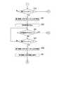
次に、図2、図6、及び図7を参照して、表示装置1によって実行される入力制御方法を説明する。図6及び図7は、入力制御方法を示すフローチャートである。図6及び図7に示すように、入力制御方法は、ステップS1〜ステップS31を含む。以下、肯定判定は「Yes」判定を示し、否定判定は「No」判定を示す。 Next, the input control method executed by the display device 1 will be described with reference to FIGS. 2, 6, and 7. 6 and 7 are flowcharts showing an input control method. As shown in FIGS. 6 and 7, the input control method includes steps S1 to S31. Hereinafter, the affirmative determination indicates a “Yes” determination, and the negative determination indicates a “No” determination.
具体的には、図2及び図6に示すように、ステップS1において、入力決定部29は、表示面5aの第3領域A3に対するタッチ入力を、有効な入力として処理することを決定する。 Specifically, as shown in FIGS. 2 and 6, in step S1, the
ステップS3において、入力決定部29は、外部装置200が表示装置1に接続されたか否かを判定する。 In step S3, the
ステップS3で否定判定されると、処理はステップS3に戻る。
一方ステップS3で肯定判定されると、処理はステップS5に進む。If a negative determination is made in step S3, the process returns to step S3.
On the other hand, if an affirmative determination is made in step S3, the process proceeds to step S5.
ステップS5において、入力決定部29は、表示装置1のモードが入力制御モードに設定されているか否かを判定する。 In step S5, the
ステップS5で否定判定されると、処理はステップS3に進む。
一方ステップS5で肯定判定されると、処理はステップS7に進む。If a negative determination is made in step S5, the process proceeds to step S3.
On the other hand, if an affirmative determination is made in step S5, the process proceeds to step S7.
ステップS7において、入力決定部29は、第1領域A1に対するタッチ入力を無効な入力として処理することを決定する。 In step S7, the
ステップS9において、表示制御部25は、第1領域A1に特定画像31を表示するように表示部5を制御する。 In step S9, the
ステップS11において、入力決定部29は、外部装置200が表示装置1から外されたか否かを判定する。 In step S11, the
ステップS11で肯定判定されると、処理はステップS1に進む。
一方ステップS11で否定判定されると、処理はステップS13に進む。If an affirmative determination is made in step S11, the process proceeds to step S1.
On the other hand, if a negative determination is made in step S11, the process proceeds to step S13.
ステップS13において、領域制御部27は、第1領域A1の移動指示が入力されたか否かを判定する。 In step S13, the
ステップS13で否定判定されると、処理は図7のステップS19に進む。
一方ステップS13で肯定判定されると、処理はステップS15に進む。If a negative determination is made in step S13, the process proceeds to step S19 in FIG.
On the other hand, if an affirmative determination is made in step S13, the process proceeds to step S15.
ステップS15において、領域制御部27は、移動指示に応じて、第1領域A1を移動する。 In step S15, the
ステップS17において、表示制御部25は、移動指示に応じて、特定画像31を移動する。その結果、特定画像31は、第1領域A1とともに移動する。そして、処理は図7のステップS19に進む。 In step S17, the
図2及び図7に示すように、ステップS19において、入力決定部29は、第1ジェスチャーを示すタッチ入力が第2領域A2で検出されたか否かを判定する。 As shown in FIGS. 2 and 7, in step S19, the
ステップS19で否定判定されると、処理は図6のステップS11に進む。
一方ステップS19で肯定判定されると、処理はステップS21に進む。If a negative determination is made in step S19, the process proceeds to step S11 of FIG.
On the other hand, if an affirmative determination is made in step S19, the process proceeds to step S21.
ステップS21において、入力決定部29は、第1領域A1に対するタッチ入力を有効な入力として処理することを決定する。 In step S21, the
ステップS23において、表示制御部25は、特定画像31を消去するように表示部5を制御する。 In step S23, the
ステップS25において、入力決定部29は、外部装置200が表示装置1から外されたか否かを判定する。 In step S25, the
ステップS25で肯定判定されると、処理は図6のステップS1に進む。
一方ステップS25で否定判定されると、処理はステップS27に進む。If an affirmative determination is made in step S25, the process proceeds to step S1 of FIG.
On the other hand, if a negative determination is made in step S25, the process proceeds to step S27.
ステップS27において、入力決定部29は、第2ジェスチャーを示すタッチ入力が第3領域A3で検出されたか否かを判定する。 In step S27, the
ステップS27で否定判定されると、処理はステップS25に進む。
一方、ステップS27で肯定判定されると、処理はステップS29に進む。If a negative determination is made in step S27, the process proceeds to step S25.
On the other hand, if an affirmative determination is made in step S27, the process proceeds to step S29.
ステップS29において、入力決定部29は、第1領域A1に対するタッチ入力を無効な入力として処理することを決定する。 In step S29, the
ステップS31において、表示制御部25は、第1領域A1に特定画像31を表示するように表示部5を制御する。そして、処理は図6のステップS11に進む。 In step S31, the
なお、図7のステップS19及びステップS27が、「外部装置200が接続された後に、表示装置1の表示面5aに対するタッチ入力が検出されたか否かを判定するステップ」に相当する。また、ステップS21及びステップS29が、「表示面5aに対するタッチ入力が検出されと判定されたときに、タッチ入力に基づいて、表示面5a上の領域のうちの第1領域A1に対するタッチ入力を、有効な入力として処理するか、無効な入力として処理するかを決定するステップ」に相当する。 Note that steps S19 and S27 in FIG. 7 correspond to "a step of determining whether or not a touch input to the
(実施形態2)
図1、図2、図8、及び図9を参照して、本発明の実施形態2に係る表示システム100について説明する。実施形態2が、外部装置200の接続に応答して第1領域A1をタッチ有効領域に設定する点で、実施形態2は実施形態1と異なる。実施形態2に係る表示システム100の構成は、実施形態1に係る表示システム100の構成と同様である。従って、実施形態2の説明において、図1及び図2を適宜参照する。以下、実施形態2が実施形態1と主に異なる点を説明する。また、入力制御モードでの各構成の処理を説明する。(Embodiment 2)
The
図1及び図2に示すように、入力決定部29は、外部装置200が表示装置1に接続されたことに応答して、第1領域A1に対するタッチ入力を、有効な入力として処理することを決定する。従って、外部装置200が接続された後において、第2ジェスチャーG2(図4)を示すタッチ入力が第3領域A3で検出されるまでは、第1領域A1に対するタッチ入力は、有効な入力として処理される。その結果、実施形態2によれば、ユーザーは、外部装置200を接続した場合に、表示面5aの全領域(具体的には第3領域A3)に対するタッチ入力を直ちに実行できる。特に、外部装置200の接続時に、ユーザーが外部装置200を第1領域A1に載置する予定のないときに、ユーザーにとって便宜である。なお、制御部21は、第2ジェスチャーG2を示すタッチ入力に関係なく、外部装置200が接続された後において、第2領域A2に対するタッチ入力を、有効な入力として処理する。 As shown in FIGS. 1 and 2, the
そして、入力決定部29は、外部装置200が接続された後において、第2ジェスチャーG2を示すタッチ入力が第3領域A3で検出されたときに、第1領域A1に対するタッチ入力を、無効な入力として処理することを決定する。従って、実施形態2によれば、ユーザーが外部装置200を第1領域A1に載置することを希望するときに、第2ジェスチャーG2を示すタッチ入力を実行することにより、容易に第1領域A1をタッチ無効領域に設定できる。 Then, when the touch input indicating the second gesture G2 is detected in the third area A3 after the
次に、図2、図8、及び図9を参照して、表示装置1によって実行される入力制御方法を説明する。図8及び図9は、入力制御方法を示すフローチャートである。図8及び図9に示すように、入力制御方法は、ステップS51〜ステップS79を含む。以下、肯定判定は「Yes」判定を示し、否定判定は「No」判定を示す。 Next, the input control method executed by the display device 1 will be described with reference to FIGS. 2, 8 and 9. 8 and 9 are flowcharts showing an input control method. As shown in FIGS. 8 and 9, the input control method includes steps S51 to S79. Hereinafter, the affirmative determination indicates a “Yes” determination, and the negative determination indicates a “No” determination.
具体的には、図2及び図8に示すように、ステップS51において、入力決定部29は、表示面5aの第3領域A3に対するタッチ入力を、有効な入力として処理することを決定する。 Specifically, as shown in FIGS. 2 and 8, in step S51, the
ステップS53において、入力決定部29は、外部装置200が表示装置1に接続されたか否かを判定する。 In step S53, the
ステップS53で否定判定されると、処理はステップS53に戻る。
一方ステップS53で肯定判定されると、処理はステップS55に進む。If a negative determination is made in step S53, the process returns to step S53.
On the other hand, if an affirmative determination is made in step S53, the process proceeds to step S55.
ステップS55において、入力決定部29は、表示装置1のモードが入力制御モードに設定されているか否かを判定する。 In step S55, the
ステップS55で否定判定されると、処理はステップS53に進む。
一方ステップS55で肯定判定されると、処理はステップS57に進む。If a negative determination is made in step S55, the process proceeds to step S53.
On the other hand, if an affirmative determination is made in step S55, the process proceeds to step S57.
ステップS57において、入力決定部29は、第1領域A1に対するタッチ入力を有効な入力として処理することを決定する。 In step S57, the
ステップS59において、入力決定部29は、外部装置200が表示装置1から外されたか否かを判定する。 In step S59, the
ステップS59で肯定判定されると、処理はステップS51に進む。
一方ステップS59で否定判定されると、処理はステップS61に進む。If an affirmative determination is made in step S59, the process proceeds to step S51.
On the other hand, if a negative determination is made in step S59, the process proceeds to step S61.
ステップS61において、入力決定部29は、第2ジェスチャーを示すタッチ入力が第3領域A3で検出されたか否かを判定する。 In step S61, the
ステップS61で否定判定されると、処理はステップS59に進む。
一方、ステップS61で肯定判定されると、処理はステップS63に進む。If a negative determination is made in step S61, the process proceeds to step S59.
On the other hand, if an affirmative determination is made in step S61, the process proceeds to step S63.
ステップS63において、入力決定部29は、第1領域A1に対するタッチ入力を無効な入力として処理することを決定する。 In step S63, the
ステップS65において、表示制御部25は、第1領域A1に特定画像31を表示するように表示部5を制御する。そして、処理は図9のステップS67に進む。 In step S65, the
図2及び図9に示すように、ステップS67において、入力決定部29は、外部装置200が表示装置1から外されたか否かを判定する。 As shown in FIGS. 2 and 9, in step S67, the
ステップS67で肯定判定されると、処理は図8のステップS51に進む。
一方、ステップS67で否定判定されると、処理はステップS69に進む。If an affirmative determination is made in step S67, the process proceeds to step S51 of FIG.
On the other hand, if a negative determination is made in step S67, the process proceeds to step S69.
ステップS69において、領域制御部27は、第1領域A1の移動指示が入力されたか否かを判定する。 In step S69, the
ステップS69で否定判定されると、処理はステップS75に進む。
一方ステップS69で肯定判定されると、処理はステップS71に進む。If a negative determination is made in step S69, the process proceeds to step S75.
On the other hand, if an affirmative determination is made in step S69, the process proceeds to step S71.
ステップS71において、領域制御部27は、移動指示に応じて、第1領域A1を移動する。 In step S71, the
ステップS73において、表示制御部25は、移動指示に応じて、特定画像31を移動する。その結果、特定画像31は、第1領域A1とともに移動する。 In step S73, the
ステップS75において、入力決定部29は、第1ジェスチャーを示すタッチ入力が第2領域A2で検出されたか否かを判定する。 In step S75, the
ステップS75で否定判定されると、処理はステップS67に進む。
一方ステップS75で肯定判定されると、処理はステップS77に進む。If a negative determination is made in step S75, the process proceeds to step S67.
On the other hand, if an affirmative determination is made in step S75, the process proceeds to step S77.
ステップS77において、入力決定部29は、第1領域A1に対するタッチ入力を有効な入力として処理することを決定する。 In step S77, the
ステップS79において、表示制御部25は、特定画像31を消去するように表示部5を制御する。そして、処理は図8のステップS59に進む。 In step S79, the
なお、図8のステップS61及び図9のステップS75が、「外部装置200が接続された後に、表示装置1の表示面5aに対するタッチ入力が検出されたか否かを判定するステップ」に相当する。また、ステップS63及びステップS77が、「表示面5aに対するタッチ入力が検出されと判定されたときに、タッチ入力に基づいて、表示面5a上の領域のうちの第1領域A1に対するタッチ入力を、有効な入力として処理するか、無効な入力として処理するかを決定するステップ」に相当する。 In addition, step S61 of FIG. 8 and step S75 of FIG. 9 correspond to "a step of determining whether or not a touch input to the
以上、図面を参照しながら本発明の実施形態について説明した。但し、本発明は、上記の実施形態に限られるものではなく、その要旨を逸脱しない範囲で種々の態様において実施することが可能である(例えば、下記(1)、(2))。また、上記の実施形態に開示されている複数の構成要素を適宜組み合わせることによって、種々の発明の形成が可能である。例えば、実施形態に示される全構成要素から幾つかの構成要素を削除してもよい。さらに、異なる実施形態にわたる構成要素を適宜組み合わせてもよい。図面は、理解しやすくするために、それぞれの構成要素を主体に模式的に示しており、図示された各構成要素の厚み、長さ、個数、間隔等は、図面作成の都合上から実際とは異なる場合もある。また、上記の実施形態で示す各構成要素の材質、形状、寸法等は一例であって、特に限定されるものではなく、本発明の効果から実質的に逸脱しない範囲で種々の変更が可能である。 The embodiments of the present invention have been described above with reference to the drawings. However, the present invention is not limited to the above-described embodiment, and can be implemented in various embodiments without departing from the gist thereof (for example, (1) and (2) below). In addition, various inventions can be formed by appropriately combining the plurality of components disclosed in the above embodiments. For example, some components may be removed from all the components shown in the embodiments. Furthermore, components over different embodiments may be combined as appropriate. In order to make the drawings easier to understand, each component is schematically shown, and the thickness, length, number, spacing, etc. of each component shown are actual for the convenience of drawing creation. May be different. Further, the material, shape, dimensions, etc. of each component shown in the above embodiment are merely examples, and are not particularly limited, and various changes can be made without substantially deviating from the effects of the present invention. is there.
(1)実施形態1及び実施形態2において、複数の外部装置200を表示装置1に接続してもよい。そして、領域制御部27は、外部装置200ごとに、表示面5aに対して第1領域A1を設定してもよい。従って、表示面5aに対して複数の第1領域A1が設定される。 (1) In the first and second embodiments, a plurality of
(2)実施形態1及び実施形態2において、外部装置200と表示装置1とは、無線接続されてもよいし、有線接続されてもよい。 (2) In the first and second embodiments, the
(3)実施形態1及び実施形態2において、第1ジェスチャーG1及び第2ジェスチャーG2の各々は、タッチ位置の移動軌跡(例えば、図形)で表されてもよいし、タッチ位置の出現(例えば、タップ)によって表されてもよい。タップの回数は、単数でもよいし、複数でもよい。 (3) In the first embodiment and the second embodiment, each of the first gesture G1 and the second gesture G2 may be represented by a movement locus (for example, a figure) of the touch position, or an appearance of the touch position (for example, a figure). It may be represented by a tap). The number of taps may be singular or plural.
本発明は、表示装置及び入力制御方法に関するものであり、産業上の利用可能性を有する。 The present invention relates to a display device and an input control method, and has industrial applicability.
1 表示装置
5 表示部
7 タッチ検出部
9 接続ポート(接続部)
25 表示制御部
27 領域制御部
29 入力決定部
200 外部装置1
25
Claims (7)
Translated fromJapanese画像を表示する表示部と、
前記表示部の表示面に対するタッチ入力を検出するタッチ検出部と、
前記外部装置が接続された後の前記表示面に対する前記タッチ入力に基づいて、前記表示面上の領域のうちの第1領域に対するタッチ入力を、有効な入力として処理するか、無効な入力として処理するかを決定する入力決定部と、
前記第1領域に対する前記タッチ入力を無効な入力として処理することが決定されたときに、前記第1領域に特定画像を表示するように前記表示部を制御する表示制御部と、
前記第1領域の移動指示が入力されたときに、前記第1領域を移動する領域制御部と、
前記外部装置が接続される接続ポートと
を備え、
前記表示制御部は、前記第1領域の移動に合わせて前記特定画像を移動するように、前記表示部を制御し、
前記第1領域は、前記表示面上の前記領域のうち、前記接続ポートに近い側と前記接続ポートから遠い側とのうち、前記近い側に偏って位置している、表示装置。
A display device to which an external device can be connected
A display unit that displays images and
A touch detection unit that detects a touch input to the display surface of the display unit,
Based on the touch input to the display surface after the external device is connected, the touch input to the first area of the area on the display surface is processed as a valid input or an invalid input. An input decision unit that decides whether to do it,
A display control unit that controls the display unit so as to display a specific image in the first area when it is determined to process the touch input for the first area as an invalid input.
When the movement instruction of the first region is inputted, and a region control unit for moving said firstregion,
It is provided witha connection port to which the external device is connected.
Wherein the display control unit so as to move the specific image according to the movement of the first region,and controls the display unit,
The first region is a display devicethat is biased toward the near side of the area on the display surface, which is closer to the connection port and farther from the connection port.
前記第2領域は、前記第1領域と異なり、
前記外部装置が接続された後において、第2ジェスチャーを示すタッチ入力が前記表示面上の前記領域のうちの第3領域で検出されたときに、前記入力決定部は、前記第1領域に対する前記タッチ入力を、無効な入力として処理することを決定し、
前記第2ジェスチャーは、前記第1ジェスチャーと異なる、請求項1に記載の表示装置。
After the external device is connected, when a touch input indicating the first gesture is detected in the second region of the region on the display surface, the input determination unit determines the input with respect to the first region. Decided to treat touch input as valid input,
The second region is different from the first region.
After the external device is connected, when the touch input indicating the second gesture is detected in the third region of the region on the display surface, the input determination unit determines the input with respect to the first region. Decided to treat touch input as invalid input,
The display device according to claim 1, wherein the second gesture is different from the first gesture.
The display device according to claim 2, wherein in response to the connection of the external device, the input determination unit determines to process the touch input for the first region as an invalid input.
The display device according to claim 2, wherein in response to the connection of the external device, the input determination unit determines to process the touch input for the first region as a valid input.
The display device according to any one ofclaims 1 to 4 , wherein the specific image includes a message indicating that the external device can be mounted.
The shape of the first region, the shape and substantially the same in plan view of the external device, or is substantially the same shape and representing an overview of the shape in plan view of the external device, claims 1 to5 The display device according to any one of the above.
前記外部装置が接続された後に、前記表示装置の表示面に対するタッチ入力が検出されたか否かを判定するステップと、
前記表示面に対する前記タッチ入力が検出されと判定されたときに、前記タッチ入力に基づいて、前記表示面上の領域のうちの第1領域に対するタッチ入力を、有効な入力として処理するか、無効な入力として処理するかを決定するステップと、
前記第1領域に対する前記タッチ入力を無効な入力として処理することが決定されたときに、前記第1領域に特定画像を表示するステップと、
前記第1領域の移動指示が入力されたときに、前記第1領域を移動するステップと、
前記第1領域の移動に合わせて前記特定画像を移動するステップと
を含み、
前記表示装置は、前記外部装置が接続される接続ポートを備え、
前記第1領域は、前記表示面上の前記領域のうち、前記接続ポートに近い側と前記接続ポートから遠い側とのうち、前記近い側に偏って位置している、入力制御方法。An input control method executed by a display device to which an external device can be connected.
After the external device is connected, a step of determining whether or not a touch input to the display surface of the display device is detected, and
When it is determined that the touch input to the display surface is detected, the touch input to the first area of the area on the display surface is treated as a valid input or invalid based on the touch input. Steps to decide whether to process as input
A step of displaying a specific image in the first area when it is determined to process the touch input for the first area as an invalid input.
When the movement instruction of the first area is input, the step of moving the first area and
Look including the step of moving the specific image according to the movement of the first region,
The display device includes a connection port to which the external device is connected.
An input control methodin which the first region is biased toward the near side of the area on the display surface, which is closer to the connection port and farther from the connection port.
Priority Applications (1)
| Application Number | Priority Date | Filing Date | Title |
|---|---|---|---|
| JP2017124988AJP6834808B2 (en) | 2017-06-27 | 2017-06-27 | Display device and input control method |
Applications Claiming Priority (1)
| Application Number | Priority Date | Filing Date | Title |
|---|---|---|---|
| JP2017124988AJP6834808B2 (en) | 2017-06-27 | 2017-06-27 | Display device and input control method |
Publications (2)
| Publication Number | Publication Date |
|---|---|
| JP2019008627A JP2019008627A (en) | 2019-01-17 |
| JP6834808B2true JP6834808B2 (en) | 2021-02-24 |
Family
ID=65026045
Family Applications (1)
| Application Number | Title | Priority Date | Filing Date |
|---|---|---|---|
| JP2017124988AExpired - Fee RelatedJP6834808B2 (en) | 2017-06-27 | 2017-06-27 | Display device and input control method |
Country Status (1)
| Country | Link |
|---|---|
| JP (1) | JP6834808B2 (en) |
- 2017
- 2017-06-27JPJP2017124988Apatent/JP6834808B2/ennot_activeExpired - Fee Related
Also Published As
| Publication number | Publication date |
|---|---|
| JP2019008627A (en) | 2019-01-17 |
Similar Documents
| Publication | Publication Date | Title |
|---|---|---|
| JP5204286B2 (en) | Electronic device and input method | |
| JP5664147B2 (en) | Information processing apparatus, information processing method, and program | |
| US9575654B2 (en) | Touch device and control method thereof | |
| JP5507494B2 (en) | Portable electronic device with touch screen and control method | |
| US20100013782A1 (en) | Touch-sensitive mobile computing device and controlling method applied thereto | |
| TWI490775B (en) | Computing device, method of operating the same and non-transitory computer readable medium | |
| JP6225911B2 (en) | Information processing apparatus, information processing method, and program | |
| CN105264870B (en) | User input using hover input | |
| JP5371798B2 (en) | Information processing apparatus, information processing method and program | |
| KR20130093043A (en) | Method and mobile device for user interface for touch and swipe navigation | |
| KR102205283B1 (en) | Electro device executing at least one application and method for controlling thereof | |
| CN104808936A (en) | Interface operation method and portable electronic device using the method | |
| JP2009003851A (en) | Information apparatus with touch panel, and icon selecting method and program used for the same | |
| JP6191567B2 (en) | Operation screen display device, image forming apparatus, and display program | |
| JP2011134273A (en) | Information processor, information processing method, and program | |
| JP6017995B2 (en) | Portable information processing apparatus, input method thereof, and computer-executable program | |
| JP5782420B2 (en) | User interface device, user interface method and program | |
| US20150123916A1 (en) | Portable terminal device, method for operating portable terminal device, and program for operating portable terminal device | |
| US20140225854A1 (en) | Display Apparatus, Display Method, and Program | |
| JP5414134B1 (en) | Touch-type input system and input control method | |
| JP6834808B2 (en) | Display device and input control method | |
| US11893229B2 (en) | Portable electronic device and one-hand touch operation method thereof | |
| US20180348994A1 (en) | Display device and computer-readable non-transitory recording medium with display control program stored thereon | |
| KR101678213B1 (en) | An apparatus for user interface by detecting increase or decrease of touch area and method thereof | |
| JP2017049904A (en) | Information processing apparatus, information processing program, and information processing method |
Legal Events
| Date | Code | Title | Description |
|---|---|---|---|
| A621 | Written request for application examination | Free format text:JAPANESE INTERMEDIATE CODE: A621 Effective date:20190628 | |
| A977 | Report on retrieval | Free format text:JAPANESE INTERMEDIATE CODE: A971007 Effective date:20200228 | |
| A131 | Notification of reasons for refusal | Free format text:JAPANESE INTERMEDIATE CODE: A131 Effective date:20200317 | |
| A521 | Request for written amendment filed | Free format text:JAPANESE INTERMEDIATE CODE: A523 Effective date:20200511 | |
| A131 | Notification of reasons for refusal | Free format text:JAPANESE INTERMEDIATE CODE: A131 Effective date:20201027 | |
| A521 | Request for written amendment filed | Free format text:JAPANESE INTERMEDIATE CODE: A523 Effective date:20201217 | |
| TRDD | Decision of grant or rejection written | ||
| A01 | Written decision to grant a patent or to grant a registration (utility model) | Free format text:JAPANESE INTERMEDIATE CODE: A01 Effective date:20210105 | |
| A61 | First payment of annual fees (during grant procedure) | Free format text:JAPANESE INTERMEDIATE CODE: A61 Effective date:20210118 | |
| R150 | Certificate of patent or registration of utility model | Ref document number:6834808 Country of ref document:JP Free format text:JAPANESE INTERMEDIATE CODE: R150 | |
| LAPS | Cancellation because of no payment of annual fees |