JP6833869B2 - Temperature-dependent adhesion between applicator and skin during tissue cooling - Google Patents
Temperature-dependent adhesion between applicator and skin during tissue coolingDownload PDFInfo
- Publication number
- JP6833869B2 JP6833869B2JP2018554644AJP2018554644AJP6833869B2JP 6833869 B2JP6833869 B2JP 6833869B2JP 2018554644 AJP2018554644 AJP 2018554644AJP 2018554644 AJP2018554644 AJP 2018554644AJP 6833869 B2JP6833869 B2JP 6833869B2
- Authority
- JP
- Japan
- Prior art keywords
- adhesive
- applicator
- skin
- cooling
- temperature
- Prior art date
- Legal status (The legal status is an assumption and is not a legal conclusion. Google has not performed a legal analysis and makes no representation as to the accuracy of the status listed.)
- Active
Links
- 238000001816coolingMethods0.000titleclaimsdescription145
- 230000001419dependent effectEffects0.000titledescription10
- 239000000853adhesiveSubstances0.000claimsdescription388
- 230000001070adhesive effectEffects0.000claimsdescription388
- 238000012546transferMethods0.000claimsdescription81
- 230000009477glass transitionEffects0.000claimsdescription35
- 230000002745absorbentEffects0.000claimsdescription24
- 239000002250absorbentSubstances0.000claimsdescription24
- 239000000758substrateSubstances0.000claimsdescription24
- 230000001965increasing effectEffects0.000claimsdescription16
- 239000002245particleSubstances0.000claimsdescription11
- 239000003349gelling agentSubstances0.000claimsdescription5
- 230000004044responseEffects0.000claimsdescription5
- 238000000926separation methodMethods0.000claimsdescription3
- 150000004676glycansChemical class0.000claimsdescription2
- 229920001282polysaccharidePolymers0.000claimsdescription2
- 239000005017polysaccharideSubstances0.000claimsdescription2
- 108090000623proteins and genesProteins0.000claimsdescription2
- 102000004169proteins and genesHuman genes0.000claimsdescription2
- 239000000725suspensionSubstances0.000claimsdescription2
- 210000003491skinAnatomy0.000description139
- 210000001519tissueAnatomy0.000description129
- 238000011282treatmentMethods0.000description118
- 238000000034methodMethods0.000description78
- PEDCQBHIVMGVHV-UHFFFAOYSA-NGlycerineChemical compoundOCC(O)COPEDCQBHIVMGVHV-UHFFFAOYSA-N0.000description63
- 210000004027cellAnatomy0.000description60
- 150000002632lipidsChemical class0.000description37
- 239000011230binding agentSubstances0.000description32
- 229930091371FructoseNatural products0.000description28
- 239000005715FructoseSubstances0.000description28
- RFSUNEUAIZKAJO-ARQDHWQXSA-NFructoseChemical compoundOC[C@H]1O[C@](O)(CO)[C@@H](O)[C@@H]1ORFSUNEUAIZKAJO-ARQDHWQXSA-N0.000description28
- 238000007920subcutaneous administrationMethods0.000description28
- 238000007710freezingMethods0.000description27
- 230000008014freezingEffects0.000description26
- 238000000315cryotherapyMethods0.000description25
- 239000012530fluidSubstances0.000description25
- 150000002772monosaccharidesChemical class0.000description25
- 230000006378damageEffects0.000description19
- 210000000577adipose tissueAnatomy0.000description18
- SZXQTJUDPRGNJN-UHFFFAOYSA-Ndipropylene glycolChemical compoundOCCCOCCCOSZXQTJUDPRGNJN-UHFFFAOYSA-N0.000description18
- 230000001225therapeutic effectEffects0.000description17
- 239000013529heat transfer fluidSubstances0.000description15
- 239000010410layerSubstances0.000description15
- 239000003795chemical substances by applicationSubstances0.000description13
- 239000002131composite materialSubstances0.000description13
- 239000002577cryoprotective agentSubstances0.000description13
- WQZGKKKJIJFFOK-GASJEMHNSA-NGlucoseNatural productsOC[C@H]1OC(O)[C@H](O)[C@@H](O)[C@@H]1OWQZGKKKJIJFFOK-GASJEMHNSA-N0.000description12
- 239000008103glucoseSubstances0.000description12
- 230000006907apoptotic processEffects0.000description11
- 230000007246mechanismEffects0.000description11
- XLYOFNOQVPJJNP-UHFFFAOYSA-NwaterSubstancesOXLYOFNOQVPJJNP-UHFFFAOYSA-N0.000description11
- 238000010438heat treatmentMethods0.000description10
- 208000014674injuryDiseases0.000description8
- 239000003638chemical reducing agentSubstances0.000description7
- 238000001514detection methodMethods0.000description7
- 239000000463materialSubstances0.000description7
- 238000012360testing methodMethods0.000description7
- DNIAPMSPPWPWGF-UHFFFAOYSA-NPropylene glycolChemical compoundCC(O)CODNIAPMSPPWPWGF-UHFFFAOYSA-N0.000description6
- 210000001789adipocyteAnatomy0.000description6
- 230000008901benefitEffects0.000description6
- WQZGKKKJIJFFOK-VFUOTHLCSA-Nbeta-D-glucoseChemical compoundOC[C@H]1O[C@@H](O)[C@H](O)[C@@H](O)[C@@H]1OWQZGKKKJIJFFOK-VFUOTHLCSA-N0.000description6
- 230000030833cell deathEffects0.000description6
- 239000004744fabricSubstances0.000description6
- 230000006870functionEffects0.000description6
- 239000000203mixtureSubstances0.000description6
- 229930006000SucroseNatural products0.000description5
- 230000009471actionEffects0.000description5
- 239000011248coating agentSubstances0.000description5
- 238000000576coating methodMethods0.000description5
- 238000004891communicationMethods0.000description5
- 150000001875compoundsChemical class0.000description5
- 238000004090dissolutionMethods0.000description5
- 230000008569processEffects0.000description5
- 239000005720sucroseSubstances0.000description5
- 230000008733traumaEffects0.000description5
- 238000010792warmingMethods0.000description5
- CZMRCDWAGMRECN-UGDNZRGBSA-NSucroseChemical compoundO[C@H]1[C@H](O)[C@@H](CO)O[C@@]1(CO)O[C@@H]1[C@H](O)[C@@H](O)[C@H](O)[C@@H](CO)O1CZMRCDWAGMRECN-UGDNZRGBSA-N0.000description4
- 210000001015abdomenAnatomy0.000description4
- 239000012790adhesive layerSubstances0.000description4
- 230000009286beneficial effectEffects0.000description4
- 230000036760body temperatureEffects0.000description4
- 230000008859changeEffects0.000description4
- 230000004087circulationEffects0.000description4
- 239000002537cosmeticSubstances0.000description4
- 230000000694effectsEffects0.000description4
- 238000009472formulationMethods0.000description4
- 239000012528membraneSubstances0.000description4
- 230000004048modificationEffects0.000description4
- 238000012986modificationMethods0.000description4
- 230000009467reductionEffects0.000description4
- 230000002829reductive effectEffects0.000description4
- 239000002904solventSubstances0.000description4
- 239000000126substanceSubstances0.000description4
- 241000282412HomoSpecies0.000description3
- 206010061218InflammationDiseases0.000description3
- 229920000297RayonPolymers0.000description3
- 208000027418Wounds and injuryDiseases0.000description3
- 230000004075alterationEffects0.000description3
- 210000003423ankleAnatomy0.000description3
- 230000001640apoptogenic effectEffects0.000description3
- 230000017531blood circulationEffects0.000description3
- 210000001217buttockAnatomy0.000description3
- 210000000170cell membraneAnatomy0.000description3
- 230000007423decreaseEffects0.000description3
- 230000003247decreasing effectEffects0.000description3
- 229940079593drugDrugs0.000description3
- 239000003814drugSubstances0.000description3
- 230000001815facial effectEffects0.000description3
- 239000000835fiberSubstances0.000description3
- 239000011521glassSubstances0.000description3
- 230000036541healthEffects0.000description3
- 206010020718hyperplasiaDiseases0.000description3
- 230000006872improvementEffects0.000description3
- 210000003127kneeAnatomy0.000description3
- 230000004130lipolysisEffects0.000description3
- 230000014759maintenance of locationEffects0.000description3
- 238000002156mixingMethods0.000description3
- 230000002028prematureEffects0.000description3
- 239000002964rayonSubstances0.000description3
- 238000001953recrystallisationMethods0.000description3
- 238000005057refrigerationMethods0.000description3
- 238000007665saggingMethods0.000description3
- 239000000523sampleSubstances0.000description3
- 210000004927skin cellAnatomy0.000description3
- 238000003860storageMethods0.000description3
- 238000005728strengtheningMethods0.000description3
- 235000000346sugarNutrition0.000description3
- 150000008163sugarsChemical class0.000description3
- 230000007704transitionEffects0.000description3
- 210000000689upper legAnatomy0.000description3
- 229920000049Carbon (fiber)Polymers0.000description2
- 229920000742CottonPolymers0.000description2
- LYCAIKOWRPUZTN-UHFFFAOYSA-NEthylene glycolChemical compoundOCCOLYCAIKOWRPUZTN-UHFFFAOYSA-N0.000description2
- XLOMVQKBTHCTTD-UHFFFAOYSA-NZinc monoxideChemical compound[Zn]=OXLOMVQKBTHCTTD-UHFFFAOYSA-N0.000description2
- QVGXLLKOCUKJST-UHFFFAOYSA-Natomic oxygenChemical compound[O]QVGXLLKOCUKJST-UHFFFAOYSA-N0.000description2
- 230000015572biosynthetic processEffects0.000description2
- 210000004369bloodAnatomy0.000description2
- 239000008280bloodSubstances0.000description2
- 238000004364calculation methodMethods0.000description2
- 239000004917carbon fiberSubstances0.000description2
- 230000015556catabolic processEffects0.000description2
- 238000006243chemical reactionMethods0.000description2
- 238000007906compressionMethods0.000description2
- 230000006835compressionEffects0.000description2
- 239000004020conductorSubstances0.000description2
- 230000008602contractionEffects0.000description2
- 238000007796conventional methodMethods0.000description2
- 239000002826coolantSubstances0.000description2
- 238000002425crystallisationMethods0.000description2
- 230000008025crystallizationEffects0.000description2
- 230000001351cycling effectEffects0.000description2
- 238000006731degradation reactionMethods0.000description2
- 210000004207dermisAnatomy0.000description2
- 230000001066destructive effectEffects0.000description2
- 238000010586diagramMethods0.000description2
- 238000000113differential scanning calorimetryMethods0.000description2
- 238000009826distributionMethods0.000description2
- 239000003292glueSubstances0.000description2
- 230000004054inflammatory processEffects0.000description2
- 230000000302ischemic effectEffects0.000description2
- 238000007443liposuctionMethods0.000description2
- 239000007788liquidSubstances0.000description2
- 238000011866long-term treatmentMethods0.000description2
- 238000005259measurementMethods0.000description2
- 238000012544monitoring processMethods0.000description2
- 230000017074necrotic cell deathEffects0.000description2
- 230000003287optical effectEffects0.000description2
- 229910052760oxygenInorganic materials0.000description2
- 239000001301oxygenSubstances0.000description2
- 239000004814polyurethaneSubstances0.000description2
- 229920002635polyurethanePolymers0.000description2
- 238000011084recoveryMethods0.000description2
- 230000010410reperfusionEffects0.000description2
- 230000002441reversible effectEffects0.000description2
- 239000003381stabilizerSubstances0.000description2
- 210000004003subcutaneous fatAnatomy0.000description2
- 230000000699topical effectEffects0.000description2
- 239000011800void materialSubstances0.000description2
- 208000016261weight lossDiseases0.000description2
- 230000004580weight lossEffects0.000description2
- HDTRYLNUVZCQOY-UHFFFAOYSA-Nα-D-glucopyranosyl-α-D-glucopyranosideNatural productsOC1C(O)C(O)C(CO)OC1OC1C(O)C(O)C(O)C(CO)O1HDTRYLNUVZCQOY-UHFFFAOYSA-N0.000description1
- OWEGMIWEEQEYGQ-UHFFFAOYSA-N100676-05-9Natural productsOC1C(O)C(O)C(CO)OC1OCC1C(O)C(O)C(O)C(OC2C(OC(O)C(O)C2O)CO)O1OWEGMIWEEQEYGQ-UHFFFAOYSA-N0.000description1
- QTBSBXVTEAMEQO-UHFFFAOYSA-MAcetateChemical compoundCC([O-])=OQTBSBXVTEAMEQO-UHFFFAOYSA-M0.000description1
- 229920001817AgarPolymers0.000description1
- 241000894006BacteriaSpecies0.000description1
- OKTJSMMVPCPJKN-UHFFFAOYSA-NCarbonChemical compound[C]OKTJSMMVPCPJKN-UHFFFAOYSA-N0.000description1
- 241000699802Cricetulus griseusSpecies0.000description1
- 229920002245Dextrose equivalentPolymers0.000description1
- 108010010803GelatinProteins0.000description1
- 206010019280Heart failuresDiseases0.000description1
- 208000031226HyperlipidaemiaDiseases0.000description1
- 206010020751HypersensitivityDiseases0.000description1
- 206010021143HypoxiaDiseases0.000description1
- GUBGYTABKSRVRQ-PICCSMPSSA-NMaltoseNatural productsO[C@@H]1[C@@H](O)[C@H](O)[C@@H](CO)O[C@@H]1O[C@@H]1[C@@H](CO)OC(O)[C@H](O)[C@H]1OGUBGYTABKSRVRQ-PICCSMPSSA-N0.000description1
- 230000005679Peltier effectEffects0.000description1
- 206010057249PhagocytosisDiseases0.000description1
- 206010037549PurpuraDiseases0.000description1
- 241001672981PurpuraSpecies0.000description1
- HDTRYLNUVZCQOY-WSWWMNSNSA-NTrehaloseNatural productsO[C@@H]1[C@@H](O)[C@@H](O)[C@@H](CO)O[C@@H]1O[C@@H]1[C@H](O)[C@@H](O)[C@@H](O)[C@@H](CO)O1HDTRYLNUVZCQOY-WSWWMNSNSA-N0.000description1
- 208000009443Vascular MalformationsDiseases0.000description1
- 206010047139VasoconstrictionDiseases0.000description1
- 239000006096absorbing agentSubstances0.000description1
- 238000009825accumulationMethods0.000description1
- 239000000654additiveSubstances0.000description1
- 230000002411adverseEffects0.000description1
- 239000008272agarSubstances0.000description1
- 238000005054agglomerationMethods0.000description1
- 230000002776aggregationEffects0.000description1
- 208000026935allergic diseaseDiseases0.000description1
- 230000007815allergyEffects0.000description1
- HDTRYLNUVZCQOY-LIZSDCNHSA-Nalpha,alpha-trehaloseChemical compoundO[C@@H]1[C@@H](O)[C@H](O)[C@@H](CO)O[C@@H]1O[C@@H]1[C@H](O)[C@@H](O)[C@H](O)[C@@H](CO)O1HDTRYLNUVZCQOY-LIZSDCNHSA-N0.000description1
- 229910052782aluminiumInorganic materials0.000description1
- XAGFODPZIPBFFR-UHFFFAOYSA-NaluminiumChemical compound[Al]XAGFODPZIPBFFR-UHFFFAOYSA-N0.000description1
- 210000003484anatomyAnatomy0.000description1
- 230000000845anti-microbial effectEffects0.000description1
- 238000003782apoptosis assayMethods0.000description1
- 210000000617armAnatomy0.000description1
- 230000001580bacterial effectEffects0.000description1
- GUBGYTABKSRVRQ-QUYVBRFLSA-Nbeta-maltoseChemical compoundOC[C@H]1O[C@H](O[C@H]2[C@H](O)[C@@H](O)[C@H](O)O[C@@H]2CO)[C@H](O)[C@@H](O)[C@@H]1OGUBGYTABKSRVRQ-QUYVBRFLSA-N0.000description1
- 230000000903blocking effectEffects0.000description1
- 230000036770blood supplyEffects0.000description1
- 230000001680brushing effectEffects0.000description1
- 229910052799carbonInorganic materials0.000description1
- 230000010428chromatin condensationEffects0.000description1
- 239000013611chromosomal DNASubstances0.000description1
- 238000004140cleaningMethods0.000description1
- 230000008645cold stressEffects0.000description1
- 239000000470constituentSubstances0.000description1
- 238000012937correctionMethods0.000description1
- 230000000959cryoprotective effectEffects0.000description1
- 238000002681cryosurgeryMethods0.000description1
- 230000034994deathEffects0.000description1
- 230000002950deficientEffects0.000description1
- 235000005911dietNutrition0.000description1
- 230000037213dietEffects0.000description1
- 150000002016disaccharidesChemical class0.000description1
- 238000006073displacement reactionMethods0.000description1
- 230000002500effect on skinEffects0.000description1
- 230000007613environmental effectEffects0.000description1
- 210000002615epidermisAnatomy0.000description1
- 230000004907fluxEffects0.000description1
- 238000005187foamingMethods0.000description1
- 150000002231fructose derivativesChemical class0.000description1
- 230000002538fungal effectEffects0.000description1
- 239000008273gelatinSubstances0.000description1
- 229920000159gelatinPolymers0.000description1
- 235000019322gelatineNutrition0.000description1
- 235000011852gelatine dessertsNutrition0.000description1
- 210000004907glandAnatomy0.000description1
- 150000002303glucose derivativesChemical class0.000description1
- 150000002334glycolsChemical class0.000description1
- 230000005484gravityEffects0.000description1
- 239000005556hormoneSubstances0.000description1
- 229940088597hormoneDrugs0.000description1
- 230000002209hydrophobic effectEffects0.000description1
- WGCNASOHLSPBMP-UHFFFAOYSA-NhydroxyacetaldehydeNatural productsOCC=OWGCNASOHLSPBMP-UHFFFAOYSA-N0.000description1
- 229920003063hydroxymethyl cellulosePolymers0.000description1
- 229940031574hydroxymethyl celluloseDrugs0.000description1
- 230000002631hypothermal effectEffects0.000description1
- 230000006910ice nucleationEffects0.000description1
- 230000028993immune responseEffects0.000description1
- 230000001939inductive effectEffects0.000description1
- 230000006749inflammatory damageEffects0.000description1
- 238000001802infusionMethods0.000description1
- 230000000977initiatory effectEffects0.000description1
- 208000028867ischemiaDiseases0.000description1
- 238000002955isolationMethods0.000description1
- 230000002147killing effectEffects0.000description1
- 210000002414legAnatomy0.000description1
- 210000000265leukocyteAnatomy0.000description1
- 230000007774longtermEffects0.000description1
- 238000004519manufacturing processMethods0.000description1
- 230000010534mechanism of actionEffects0.000description1
- 230000002503metabolic effectEffects0.000description1
- 230000004060metabolic processEffects0.000description1
- 229910052751metalInorganic materials0.000description1
- 239000002184metalSubstances0.000description1
- VNWKTOKETHGBQD-UHFFFAOYSA-NmethaneChemical compoundCVNWKTOKETHGBQD-UHFFFAOYSA-N0.000description1
- 150000002771monosaccharide derivativesChemical class0.000description1
- 230000004660morphological changeEffects0.000description1
- 210000000663muscle cellAnatomy0.000description1
- 210000003739neckAnatomy0.000description1
- 210000005036nerveAnatomy0.000description1
- 231100000252nontoxicToxicity0.000description1
- 230000003000nontoxic effectEffects0.000description1
- 231100000862numbnessToxicity0.000description1
- 230000004792oxidative damageEffects0.000description1
- 239000005022packaging materialSubstances0.000description1
- 206010033675panniculitisDiseases0.000description1
- 230000036961partial effectEffects0.000description1
- 230000002688persistenceEffects0.000description1
- 210000001539phagocyteAnatomy0.000description1
- 230000008782phagocytosisEffects0.000description1
- 230000002399phagocytotic effectEffects0.000description1
- 238000005191phase separationMethods0.000description1
- 229920001451polypropylene glycolPolymers0.000description1
- 239000011148porous materialSubstances0.000description1
- 238000004321preservationMethods0.000description1
- 238000003825pressingMethods0.000description1
- 230000005522programmed cell deathEffects0.000description1
- 239000013074reference sampleSubstances0.000description1
- 230000024042response to gravityEffects0.000description1
- 230000006903response to temperatureEffects0.000description1
- 238000012552reviewMethods0.000description1
- 210000001732sebaceous glandAnatomy0.000description1
- GCLGEJMYGQKIIW-UHFFFAOYSA-Hsodium hexametaphosphateChemical compound[Na]OP1(=O)OP(=O)(O[Na])OP(=O)(O[Na])OP(=O)(O[Na])OP(=O)(O[Na])OP(=O)(O[Na])O1GCLGEJMYGQKIIW-UHFFFAOYSA-H0.000description1
- 239000007787solidSubstances0.000description1
- 238000000527sonicationMethods0.000description1
- 238000000528statistical testMethods0.000description1
- 210000004304subcutaneous tissueAnatomy0.000description1
- 239000001797sucrose acetate isobutyrateSubstances0.000description1
- 235000010983sucrose acetate isobutyrateNutrition0.000description1
- UVGUPMLLGBCFEJ-SWTLDUCYSA-Nsucrose acetate isobutyrateChemical compoundCC(C)C(=O)O[C@H]1[C@H](OC(=O)C(C)C)[C@@H](COC(=O)C(C)C)O[C@@]1(COC(C)=O)O[C@@H]1[C@H](OC(=O)C(C)C)[C@@H](OC(=O)C(C)C)[C@H](OC(=O)C(C)C)[C@@H](COC(C)=O)O1UVGUPMLLGBCFEJ-SWTLDUCYSA-N0.000description1
- 238000004781supercoolingMethods0.000description1
- 230000002459sustained effectEffects0.000description1
- 210000000106sweat glandAnatomy0.000description1
- 230000008961swellingEffects0.000description1
- 239000006188syrupSubstances0.000description1
- 235000020357syrupNutrition0.000description1
- 230000009885systemic effectEffects0.000description1
- 238000002076thermal analysis methodMethods0.000description1
- 230000001052transient effectEffects0.000description1
- 238000013519translationMethods0.000description1
- 230000000472traumatic effectEffects0.000description1
- 230000002792vascularEffects0.000description1
- 230000025033vasoconstrictionEffects0.000description1
- 239000002699waste materialSubstances0.000description1
- 238000004804windingMethods0.000description1
- 230000037303wrinklesEffects0.000description1
- 239000011787zinc oxideSubstances0.000description1
Images


Classifications
- A—HUMAN NECESSITIES
- A61—MEDICAL OR VETERINARY SCIENCE; HYGIENE
- A61F—FILTERS IMPLANTABLE INTO BLOOD VESSELS; PROSTHESES; DEVICES PROVIDING PATENCY TO, OR PREVENTING COLLAPSING OF, TUBULAR STRUCTURES OF THE BODY, e.g. STENTS; ORTHOPAEDIC, NURSING OR CONTRACEPTIVE DEVICES; FOMENTATION; TREATMENT OR PROTECTION OF EYES OR EARS; BANDAGES, DRESSINGS OR ABSORBENT PADS; FIRST-AID KITS
- A61F7/00—Heating or cooling appliances for medical or therapeutic treatment of the human body
- A61F7/02—Compresses or poultices for effecting heating or cooling
- A—HUMAN NECESSITIES
- A61—MEDICAL OR VETERINARY SCIENCE; HYGIENE
- A61F—FILTERS IMPLANTABLE INTO BLOOD VESSELS; PROSTHESES; DEVICES PROVIDING PATENCY TO, OR PREVENTING COLLAPSING OF, TUBULAR STRUCTURES OF THE BODY, e.g. STENTS; ORTHOPAEDIC, NURSING OR CONTRACEPTIVE DEVICES; FOMENTATION; TREATMENT OR PROTECTION OF EYES OR EARS; BANDAGES, DRESSINGS OR ABSORBENT PADS; FIRST-AID KITS
- A61F7/00—Heating or cooling appliances for medical or therapeutic treatment of the human body
- A—HUMAN NECESSITIES
- A61—MEDICAL OR VETERINARY SCIENCE; HYGIENE
- A61B—DIAGNOSIS; SURGERY; IDENTIFICATION
- A61B18/00—Surgical instruments, devices or methods for transferring non-mechanical forms of energy to or from the body
- A61B18/02—Surgical instruments, devices or methods for transferring non-mechanical forms of energy to or from the body by cooling, e.g. cryogenic techniques
- A—HUMAN NECESSITIES
- A61—MEDICAL OR VETERINARY SCIENCE; HYGIENE
- A61F—FILTERS IMPLANTABLE INTO BLOOD VESSELS; PROSTHESES; DEVICES PROVIDING PATENCY TO, OR PREVENTING COLLAPSING OF, TUBULAR STRUCTURES OF THE BODY, e.g. STENTS; ORTHOPAEDIC, NURSING OR CONTRACEPTIVE DEVICES; FOMENTATION; TREATMENT OR PROTECTION OF EYES OR EARS; BANDAGES, DRESSINGS OR ABSORBENT PADS; FIRST-AID KITS
- A61F7/00—Heating or cooling appliances for medical or therapeutic treatment of the human body
- A61F7/007—Heating or cooling appliances for medical or therapeutic treatment of the human body characterised by electric heating
- C—CHEMISTRY; METALLURGY
- C09—DYES; PAINTS; POLISHES; NATURAL RESINS; ADHESIVES; COMPOSITIONS NOT OTHERWISE PROVIDED FOR; APPLICATIONS OF MATERIALS NOT OTHERWISE PROVIDED FOR
- C09J—ADHESIVES; NON-MECHANICAL ASPECTS OF ADHESIVE PROCESSES IN GENERAL; ADHESIVE PROCESSES NOT PROVIDED FOR ELSEWHERE; USE OF MATERIALS AS ADHESIVES
- C09J11/00—Features of adhesives not provided for in group C09J9/00, e.g. additives
- C09J11/02—Non-macromolecular additives
- C09J11/06—Non-macromolecular additives organic
- C—CHEMISTRY; METALLURGY
- C09—DYES; PAINTS; POLISHES; NATURAL RESINS; ADHESIVES; COMPOSITIONS NOT OTHERWISE PROVIDED FOR; APPLICATIONS OF MATERIALS NOT OTHERWISE PROVIDED FOR
- C09J—ADHESIVES; NON-MECHANICAL ASPECTS OF ADHESIVE PROCESSES IN GENERAL; ADHESIVE PROCESSES NOT PROVIDED FOR ELSEWHERE; USE OF MATERIALS AS ADHESIVES
- C09J7/00—Adhesives in the form of films or foils
- A—HUMAN NECESSITIES
- A61—MEDICAL OR VETERINARY SCIENCE; HYGIENE
- A61F—FILTERS IMPLANTABLE INTO BLOOD VESSELS; PROSTHESES; DEVICES PROVIDING PATENCY TO, OR PREVENTING COLLAPSING OF, TUBULAR STRUCTURES OF THE BODY, e.g. STENTS; ORTHOPAEDIC, NURSING OR CONTRACEPTIVE DEVICES; FOMENTATION; TREATMENT OR PROTECTION OF EYES OR EARS; BANDAGES, DRESSINGS OR ABSORBENT PADS; FIRST-AID KITS
- A61F7/00—Heating or cooling appliances for medical or therapeutic treatment of the human body
- A61F2007/0001—Body part
- A61F2007/0002—Head or parts thereof
- A61F2007/0009—Throat or neck
- A61F2007/0011—Neck only
- A—HUMAN NECESSITIES
- A61—MEDICAL OR VETERINARY SCIENCE; HYGIENE
- A61F—FILTERS IMPLANTABLE INTO BLOOD VESSELS; PROSTHESES; DEVICES PROVIDING PATENCY TO, OR PREVENTING COLLAPSING OF, TUBULAR STRUCTURES OF THE BODY, e.g. STENTS; ORTHOPAEDIC, NURSING OR CONTRACEPTIVE DEVICES; FOMENTATION; TREATMENT OR PROTECTION OF EYES OR EARS; BANDAGES, DRESSINGS OR ABSORBENT PADS; FIRST-AID KITS
- A61F7/00—Heating or cooling appliances for medical or therapeutic treatment of the human body
- A61F2007/0001—Body part
- A61F2007/0002—Head or parts thereof
- A61F2007/0014—Chin
- A—HUMAN NECESSITIES
- A61—MEDICAL OR VETERINARY SCIENCE; HYGIENE
- A61F—FILTERS IMPLANTABLE INTO BLOOD VESSELS; PROSTHESES; DEVICES PROVIDING PATENCY TO, OR PREVENTING COLLAPSING OF, TUBULAR STRUCTURES OF THE BODY, e.g. STENTS; ORTHOPAEDIC, NURSING OR CONTRACEPTIVE DEVICES; FOMENTATION; TREATMENT OR PROTECTION OF EYES OR EARS; BANDAGES, DRESSINGS OR ABSORBENT PADS; FIRST-AID KITS
- A61F7/00—Heating or cooling appliances for medical or therapeutic treatment of the human body
- A61F2007/0054—Heating or cooling appliances for medical or therapeutic treatment of the human body with a closed fluid circuit, e.g. hot water
- A61F2007/0056—Heating or cooling appliances for medical or therapeutic treatment of the human body with a closed fluid circuit, e.g. hot water for cooling
- A—HUMAN NECESSITIES
- A61—MEDICAL OR VETERINARY SCIENCE; HYGIENE
- A61F—FILTERS IMPLANTABLE INTO BLOOD VESSELS; PROSTHESES; DEVICES PROVIDING PATENCY TO, OR PREVENTING COLLAPSING OF, TUBULAR STRUCTURES OF THE BODY, e.g. STENTS; ORTHOPAEDIC, NURSING OR CONTRACEPTIVE DEVICES; FOMENTATION; TREATMENT OR PROTECTION OF EYES OR EARS; BANDAGES, DRESSINGS OR ABSORBENT PADS; FIRST-AID KITS
- A61F7/00—Heating or cooling appliances for medical or therapeutic treatment of the human body
- A61F7/007—Heating or cooling appliances for medical or therapeutic treatment of the human body characterised by electric heating
- A61F2007/0075—Heating or cooling appliances for medical or therapeutic treatment of the human body characterised by electric heating using a Peltier element, e.g. near the spot to be heated or cooled
- A—HUMAN NECESSITIES
- A61—MEDICAL OR VETERINARY SCIENCE; HYGIENE
- A61F—FILTERS IMPLANTABLE INTO BLOOD VESSELS; PROSTHESES; DEVICES PROVIDING PATENCY TO, OR PREVENTING COLLAPSING OF, TUBULAR STRUCTURES OF THE BODY, e.g. STENTS; ORTHOPAEDIC, NURSING OR CONTRACEPTIVE DEVICES; FOMENTATION; TREATMENT OR PROTECTION OF EYES OR EARS; BANDAGES, DRESSINGS OR ABSORBENT PADS; FIRST-AID KITS
- A61F7/00—Heating or cooling appliances for medical or therapeutic treatment of the human body
- A61F2007/0087—Hand-held applicators
- A—HUMAN NECESSITIES
- A61—MEDICAL OR VETERINARY SCIENCE; HYGIENE
- A61F—FILTERS IMPLANTABLE INTO BLOOD VESSELS; PROSTHESES; DEVICES PROVIDING PATENCY TO, OR PREVENTING COLLAPSING OF, TUBULAR STRUCTURES OF THE BODY, e.g. STENTS; ORTHOPAEDIC, NURSING OR CONTRACEPTIVE DEVICES; FOMENTATION; TREATMENT OR PROTECTION OF EYES OR EARS; BANDAGES, DRESSINGS OR ABSORBENT PADS; FIRST-AID KITS
- A61F7/00—Heating or cooling appliances for medical or therapeutic treatment of the human body
- A61F2007/0093—Heating or cooling appliances for medical or therapeutic treatment of the human body programmed
- A—HUMAN NECESSITIES
- A61—MEDICAL OR VETERINARY SCIENCE; HYGIENE
- A61F—FILTERS IMPLANTABLE INTO BLOOD VESSELS; PROSTHESES; DEVICES PROVIDING PATENCY TO, OR PREVENTING COLLAPSING OF, TUBULAR STRUCTURES OF THE BODY, e.g. STENTS; ORTHOPAEDIC, NURSING OR CONTRACEPTIVE DEVICES; FOMENTATION; TREATMENT OR PROTECTION OF EYES OR EARS; BANDAGES, DRESSINGS OR ABSORBENT PADS; FIRST-AID KITS
- A61F7/00—Heating or cooling appliances for medical or therapeutic treatment of the human body
- A61F7/02—Compresses or poultices for effecting heating or cooling
- A61F2007/0225—Compresses or poultices for effecting heating or cooling connected to the body or a part thereof
- A61F2007/0226—Compresses or poultices for effecting heating or cooling connected to the body or a part thereof adhesive, self-sticking
- A—HUMAN NECESSITIES
- A61—MEDICAL OR VETERINARY SCIENCE; HYGIENE
- A61F—FILTERS IMPLANTABLE INTO BLOOD VESSELS; PROSTHESES; DEVICES PROVIDING PATENCY TO, OR PREVENTING COLLAPSING OF, TUBULAR STRUCTURES OF THE BODY, e.g. STENTS; ORTHOPAEDIC, NURSING OR CONTRACEPTIVE DEVICES; FOMENTATION; TREATMENT OR PROTECTION OF EYES OR EARS; BANDAGES, DRESSINGS OR ABSORBENT PADS; FIRST-AID KITS
- A61F7/00—Heating or cooling appliances for medical or therapeutic treatment of the human body
- A61F7/02—Compresses or poultices for effecting heating or cooling
- A61F2007/0225—Compresses or poultices for effecting heating or cooling connected to the body or a part thereof
- A61F2007/0239—Compresses or poultices for effecting heating or cooling connected to the body or a part thereof using vacuum
- A—HUMAN NECESSITIES
- A61—MEDICAL OR VETERINARY SCIENCE; HYGIENE
- A61F—FILTERS IMPLANTABLE INTO BLOOD VESSELS; PROSTHESES; DEVICES PROVIDING PATENCY TO, OR PREVENTING COLLAPSING OF, TUBULAR STRUCTURES OF THE BODY, e.g. STENTS; ORTHOPAEDIC, NURSING OR CONTRACEPTIVE DEVICES; FOMENTATION; TREATMENT OR PROTECTION OF EYES OR EARS; BANDAGES, DRESSINGS OR ABSORBENT PADS; FIRST-AID KITS
- A61F7/00—Heating or cooling appliances for medical or therapeutic treatment of the human body
- A61F7/02—Compresses or poultices for effecting heating or cooling
- A61F2007/0282—Compresses or poultices for effecting heating or cooling for particular medical treatments or effects
- A61F2007/029—Fat cell removal or destruction by non-ablative heat treatment
Landscapes
- Health & Medical Sciences (AREA)
- Life Sciences & Earth Sciences (AREA)
- Engineering & Computer Science (AREA)
- Biomedical Technology (AREA)
- Heart & Thoracic Surgery (AREA)
- Animal Behavior & Ethology (AREA)
- General Health & Medical Sciences (AREA)
- Public Health (AREA)
- Veterinary Medicine (AREA)
- Vascular Medicine (AREA)
- Surgery (AREA)
- Physics & Mathematics (AREA)
- Nuclear Medicine, Radiotherapy & Molecular Imaging (AREA)
- Thermal Sciences (AREA)
- Chemical & Material Sciences (AREA)
- Organic Chemistry (AREA)
- Otolaryngology (AREA)
- Medical Informatics (AREA)
- Molecular Biology (AREA)
- Thermotherapy And Cooling Therapy Devices (AREA)
- Surgical Instruments (AREA)
- Application Of Or Painting With Fluid Materials (AREA)
Description
Translated fromJapanese本開示内容、すなわち本発明は、例えばクライオリポレーシス(脂肪冷却痩身と呼ばれる場合があり、低温脂肪分解または脂肪凍死法と呼ばれる場合もある)およびクライオリシス(冷凍溶解と呼ばれる場合がある)との関連において組織の冷却に関する。 The present disclosure, that is, the present invention, is described, for example, as cryoliporesis (sometimes referred to as fat cooling slimming, sometimes referred to as hypothermia or lipolysis) and cryolysis (sometimes referred to as cryolysis) In the context of tissue cooling.
〔関連出願の説明〕
本願は、2016年1月7日に出願された米国特許仮出願第62/276,131号の先の出願日に関する権益を主張する出願であり、この米国特許仮出願を参照により引用し、その記載内容全体を本明細書の一部とする。[Explanation of related applications]
This application is an application claiming interests relating to the earlier filing date of U.S. Patent Provisional Application No. 62 / 276,131 filed on January 7, 2016, which is cited by reference from this U.S. Patent Provisional Application. The entire description is incorporated herein by reference.
〔参照による引用〕
本願の譲受人に譲渡された以下の米国特許出願、米国特許出願公開および米国特許を参照により引用し、これらの記載内容全体を本明細書の一部とする。[Quote by reference]
The following U.S. patent applications, U.S. patent application publications and U.S. patents assigned to the assignee of the present application are cited by reference and the entire description thereof is incorporated herein by reference.
米国特許出願公開第2008/0287839号明細書(発明の名称:METHOD OF ENHANCED REMOVAL OF HEAT FROM SUBCUTANEOUS LIPID-RICH CELLS AND TREATMENT APPARATUS HAVING AN ACTUATOR) U.S. Patent Application Publication No. 2008/0287839 (Title of Invention: METHOD OF ENHANCED REMOVAL OF HEAT FROM SUBCUTANEOUS LIPID-RICH CELLS AND TREATMENT APPARATUS HAVING AN ACTUATOR)
米国特許第6,032,675号明細書(発明の名称:FREEZING METHOD FOR CONTROLLED REMOVAL OF FATTY TISSUE BY LIPOSUCTION) U.S. Pat. No. 6,032,675 (Title of Invention: FREEZING METHOD FOR CONTROLLED REMOVAL OF FATTY TISSUE BY LIPOSUCTION)
米国特許出願公開第2007/0255362号明細書(発明の名称:CRYOPROTECTANT FOR USE WITH A TREATMENT DEVICE FOR IMPROVED COOLING OF SUBCUTANEOUS LIPID-RICH CELLS) U.S. Patent Application Publication No. 2007/0255362 (Title of Invention: CRYOPROTECTANT FOR USE WITH A TREATMENT DEVICE FOR IMPROVED COOLING OF SUBCUTANEOUS LIPID-RICH CELLS)
米国特許第7,854,754号明細書(発明の名称:COOLING DEVICE FOR REMOVING HEAT FROM SUBCUTANEOUS LIPID-RICH CELLS) U.S. Pat. No. 7,854,754 (Title of Invention: COOLING DEVICE FOR REMOVING HEAT FROM SUBCUTANEOUS LIPID-RICH CELLS)
米国特許出願公開第2011/0066216号明細書(発明の名称:COOLING DEVICE FOR REMOVING HEAT FROM SUBCUTANEOUS LIPID-RICH CELLS) U.S. Patent Application Publication No. 2011/0066216 (Title of Invention: COOLING DEVICE FOR REMOVING HEAT FROM SUBCUTANEOUS LIPID-RICH CELLS)
米国特許出願公開第2008/0077201号明細書(発明の名称:COOLING DEVICES WITH FLEXIBLE SENSORS) U.S. Patent Application Publication No. 2008/0077201 (Title of Invention: COOLING DEVICES WITH FLEXIBLE SENSORS)
米国特許出願公開第2008/0077211号明細書(発明の名称:COOLING DEVICE HAVING A PLURALITY OF CONTROLLABLE COOLING ELEMENTS TO PROVIDE A PREDETERMINED COOLING PROFILE) U.S. Patent Application Publication No. 2008/0077211 (Title of Invention: COOLING DEVICE HAVING A PLURALITY OF CONTROLLABLE COOLING ELEMENTS TO PROVIDE A PREDETERMINED COOLING PROFILE)
2007年10月31日に出願された米国特許出願公開第2009/0118722号明細書(発明の名称:METHOD AND APPARATUS FOR COOLING SUBCUTANEOUS LIPID-RICH CELLS OR TISSUE) U.S. Patent Application Publication No. 2009/0118722 filed on October 31, 2007 (Title of Invention: METHOD AND APPARATUS FOR COOLING SUBCUTANEOUS LIPID-RICH CELLS OR TISSUE)
米国特許出願公開第2009/0018624号明細書(発明の名称:LIMITING USE OF DISPOSABLE SYSTEM PATIENT PROTECTION DEVICES) U.S. Patent Application Publication No. 2009/0018624 (Title of Invention: LIMITED USE OF DISPOSABLE SYSTEM PATIENT PROTECTION DEVICES)
米国特許出願公開第2009/0018623号明細書(発明の名称:SYSTEM FOR TREATING LIPID-RICH REGIONS) U.S. Patent Application Publication No. 2009/0018623 (Title of Invention: SYSTEM FOR TREATING LIPID-RICH REGIONS)
米国特許出願公開第2009/0018625号明細書(発明の名称:MANAGING SYSTEM TEMPERATURE TO REMOVE HEAT FROM LIPID-RICH REGIONS) U.S. Patent Application Publication No. 2009/0018625 (Title of Invention: MANAGING SYSTEM TEMPERATURE TO REMOVE HEAT FROM LIPID-RICH REGIONS)
米国特許出願公開第2009/0018627号明細書(発明の名称:SECURE SYSTEM FOR REMOVING HEAT FROM LIPID-RICH REGIONS) U.S. Patent Application Publication No. 2009/0018627 (Title of Invention: SECURE SYSTEM FOR REMOVING HEAT FROM LIPID-RICH REGIONS)
米国特許出願公開第2009/0018626号明細書(発明の名称:USER INTERFACES FOR A SYSTEM THAT REMOVES HEAT FROM LIPID-RICH REGIONS) U.S. Patent Application Publication No. 2009/0018626 (Title of Invention: USER INTERFACES FOR A SYSTEM THAT REMOVES HEAT FROM LIPID-RICH REGIONS)
米国特許第6,041,787号明細書(発明の名称:USE OF CRYOPROTECTIVE AGENT COMPOUNDS DURING CRYOSURGERY) U.S. Pat. No. 6,041,787 (Invention name: USE OF CRYOPROTECTIVE AGENT COMPOUNDS DURING CRYOSURGERY)
米国特許第8,285,390号明細書(発明の名称:MONITORING THE COOLING OF SUBCUTANEOUS LIPID-RICH CELLS, SUCH AS THE COOLING OF ADIPOSE TISSUE) U.S. Pat. No. 8,285,390 (Title of Invention: MONITORING THE COOLING OF SUBCUTANEOUS LIPID-RICH CELLS, SUCH AS THE COOLING OF ADIPOSE TISSUE)
米国特許第8,275,442号明細書(発明の名称:TREATMENT PLANNING SYSTEMS AND METHODS FOR BODY CONTOURING APPLICATIONS) U.S. Pat. No. 8,275,442 (Title of Invention: TREATMENT PLANNING SYSTEMS AND METHODS FOR BODY CONTOURING APPLICATIONS)
米国特許出願第12/275,002号明細書(発明の名称:APPARATUS WITH HYDROPHILIC RESERVOIRS FOR COOLING SUBCUTANEOUS LIPID-RICH CELLS) U.S. Patent Application No. 12 / 275,002 (Title of Invention: APPARATUS WITH HYDROPHILIC RESERVOIRS FOR COOLING SUBCUTANEOUS LIPID-RICH CELLS)
米国特許出願第12/275,014号明細書(発明の名称:APPARATUS WITH HYDROPHOBIC FILTERS FOR REMOVING HEAT FROM SUBCUTANEOUS LIPID- RICH CELLS) U.S. Patent Application No. 12 / 275,014 (Title of Invention: APPARATUS WITH HYDROPHOBIC FILTERS FOR REMOVING HEAT FROM SUBCUTANEOUS LIPID- RICH CELLS)
米国特許出願公開第2010/0152824号明細書(発明の名称:SYSTEMS AND METHODS WITH INTERRUPT/RESUME CAPABILITIES FOR COOLING SUBCUTANEOUS LIPID-RICH CELLS) U.S. Patent Application Publication No. 2010/0152824 (Title of Invention: SYSTEMS AND METHODS WITH INTERRUPT / RESUME CAPABILITIES FOR COOLING SUBCUTANEOUS LIPID-RICH CELLS)
米国特許第8,192,474号明細書(発明の名称:TISSUE TREATMENT METHODS) U.S. Pat. No. 8,192,474 (Title of Invention: TISSUE TREATMENT METHODS)
米国特許出願公開第2010/0280582号明細書(発明の名称:DEVICE, SYSTEM AND METHOD FOR REMOVING HEAT FROM SUBCUTANEOUS LIPID-RICH CELLS) U.S. Patent Application Publication No. 2010/0280582 (Title of Invention: DEVICE, SYSTEM AND METHOD FOR REMOVING HEAT FROM SUBCUTANEOUS LIPID-RICH CELLS)
米国特許出願公開第2012/0022518号明細書(発明の名称:COMBINED MODALITY TREATMENT SYSTEMS, METHODS AND APPARATUS FOR BODY CONTOURING APPLICATIONS) U.S. Patent Application Publication No. 2012/0022518 (Title of Invention: COMBINED MODALITY TREATMENT SYSTEMS, METHODS AND APPARATUS FOR BODY CONTOURING APPLICATIONS)
米国特許出願公開第2011/0238050号明細書(発明の名称:HOME-USE APPLICATORS FOR NON-INVASIVELY REMOVING HEAT FROM SUBCUTANEOUS LIPID-RICH CELLS VIA PHASE CHANGE COOLANTS, AND ASSOCIATED DEVICES, SYSTEMS AND METHODS) U.S. Patent Application Publication No. 2011/0238050 (Title of Invention: HOME-USE APPLICATORS FOR NON-INVASIVELY REMOVING HEAT FROM SUBCUTANEOUS LIPID-RICH CELLS VIA PHASE CHANGE COOLANTS, AND ASSOCIATED DEVICES, SYSTEMS AND METHODS)
米国特許出願公開第2011/0238051号明細書(発明の名称:HOME-USE APPLICATORS FOR NON-INVASIVELY REMOVING HEAT FROM SUBCUTANEOUS LIPID-RICH CELLS VIA PHASE CHANGE COOLANTS, AND ASSOCIATED DEVICES, SYSTEMS AND METHODS) U.S. Patent Application Publication No. 2011/0238051 (Title of Invention: HOME-USE APPLICATORS FOR NON-INVASIVELY REMOVING HEAT FROM SUBCUTANEOUS LIPID-RICH CELLS VIA PHASE CHANGE COOLANTS, AND ASSOCIATED DEVICES, SYSTEMS AND METHODS)
米国特許出願公開第2012/0239123号明細書(発明の名称:DEVICES, APPLICATION SYSTEMS AND METHODS WITH LOCALIZED HEAT FLUX ZONES FOR REMOVING HEAT FROM SUBCUTANEOUS LIPID-RICH CELLS) U.S. Patent Application Publication No. 2012/0239123 (Title of Invention: DEVICES, APPLICATION SYSTEMS AND METHODS WITH LOCALIZED HEAT FLUX ZONES FOR REMOVING HEAT FROM SUBCUTANEOUS LIPID-RICH CELLS)
米国特許出願第13/830,413号明細書(発明の名称:MULTI-MODALITY TREATMENT SYSTEMS, METHODS AND APPARATUS FOR ALTERING SUBCUTANEOUS LIPID-RICH TISSUE) U.S. Patent Application No. 13 / 830,413 (Title of Invention: MULTI-MODALITY TREATMENT SYSTEMS, METHODS AND APPARATUS FOR ALTERING SUBCUTANEOUS LIPID-RICH TISSUE)
米国特許出願第13/830,027号明細書(発明の名称:TREATMENT SYSTEMS WITH FLUID MIXING SYSTEMS AND FLUID-COOLED APPLICATORS AND METHODS OF USING THE SAME) U.S. Patent Application No. 13 / 830,027 (Title of Invention: TREATMENT SYSTEMS WITH FLUID MIXING SYSTEMS AND FLUID-COOLED APPLICATORS AND METHODS OF USING THE SAME)
米国特許出願第11/528,225号明細書(発明の名称:COOLING DEVICE HAVING A PLURALITY OF CONTROLLABLE COOLING ELEMENTS TO PROVIDE A PREDETERMINED COOLING PROFILE) U.S. Patent Application No. 11 / 528,225 (Title of Invention: COOLING DEVICE HAVING A PLURALITY OF CONTROLLABLE COOLING ELEMENTS TO PROVIDE A PREDETERMINED COOLING PROFILE)
米国特許第8,285,390号明細書(発明の名称:MONITORING THE COOLING OF SUBCUTANEOUS LIPID-RICH CELLS, SUCH AS THE COOLING OF ADIPOSE TISSUE) U.S. Pat. No. 8,285,390 (Title of Invention: MONITORING THE COOLING OF SUBCUTANEOUS LIPID-RICH CELLS, SUCH AS THE COOLING OF ADIPOSE TISSUE)
引用により参照した本願の譲受人に譲渡された上記米国特許出願、上記米国特許出願公開および米国特許または任意他の文献が本発明と抵触する限りにおいて、本発明の範囲が調整される。 The scope of the invention is adjusted to the extent that the US patent application, the publication of the US patent application and the US patent or any other document transferred to the assignee of the present application referenced by reference conflict with the invention.
過剰の体脂肪または脂肪組織が患者(被験者)の体の種々の場所に存在している場合があり、そして容姿を損ねる場合がある。あご下および/または首(頸部)の周りの過剰の皮下脂肪は、外見上見栄えが悪い場合があり、場合によっては「二重あご(下あごまたはオトガイ)」を生じさせる場合がある。二重あごは、皮膚の伸びおよび/またはたるみを生じさせる場合があり、その結果、不快感もまた生じる場合がある。さらに、表在性の脂肪区画内の過剰の脂肪組織は、たるんだ顔面構造、例えばたるんだ頬を生じさせる場合があり、それによっても望ましくない外観が生じる。過剰の体脂肪は、腹部、大腿部、臀部、膝、および腕ならびに他の場所にも付く場合がある。 Excess body fat or adipose tissue may be present in various parts of the patient's (subject's) body and may be disfiguring. Excessive subcutaneous fat under the chin and / or around the neck (neck) may look unattractive and in some cases may result in a "double chin (lower chin or chin)". Double chin can cause skin stretch and / or sagging, which can result in discomfort as well. In addition, excess adipose tissue within the superficial adipose tissue can result in sagging facial structures, such as sagging cheeks, which also results in an unwanted appearance. Excess body fat may also be attached to the abdomen, thighs, buttocks, knees, and arms and elsewhere.
人体の美的改善には、脂肪組織の選択的な除去が必要とされる場合がある。しかしながら、この目的のための侵襲的手技(例えば、脂肪吸引)は、比較的高いコスト、長い回復期間、おおよび合併症の恐れの増大と関連する傾向がある。脂肪組織、例えばオトガイ下のまたは顔面脂肪組織を減少させる薬剤の注入を行うと、相当な腫張、紫斑、疼痛、しびれ、および/または硬化が生じる場合がある。脂肪組織を減少させるための従来の非侵襲的治療は、典型的には、規則的運動、局所用剤の塗布、減量用薬剤の使用、ダイエット、またはこれらの治療の組合せを含む。これら非侵襲的治療の一欠点は、これら非侵襲的治療がある特定の環境のもとでは有効ではない場合があり、それどころか実現可能ではないということにある。例えば、個人が身体的に怪我をしているかまたは病気であるときには、規則的な運動は、選択肢となり得ない。局所用剤および経口投与減量薬は、別の例としてこれらが望ましくない反応(例えば、アレルギーまたは他の陰性反応)を生じさせる場合にはオプションとはならない。加うるに、非侵襲的治療は、脂肪過多の特定の領域を選択的に減少させる上では効果がない場合がある。例えば、首、後、頬などの周りの局所的な脂肪を落とすことは、全体的なまたは全身の減量法を用いては達成できない場合が多い。 Aesthetic improvement of the human body may require selective removal of adipose tissue. However, invasive procedures for this purpose (eg, liposuction) tend to be associated with relatively high costs, long recovery periods, and increased risk of complications. Infusion of agents that reduce adipose tissue, such as under the submental or facial adipose tissue, may result in significant swelling, purpura, pain, numbness, and / or hardening. Traditional non-invasive treatments for reducing adipose tissue typically include regular exercise, topical application, weight loss drug use, diet, or a combination of these treatments. One drawback of these non-invasive treatments is that these non-invasive treatments may not be effective under certain circumstances and, on the contrary, are not feasible. For example, regular exercise may not be an option when an individual is physically injured or ill. Topical and oral dose-reducing agents are not optional if, in another example, they cause an unwanted reaction (eg, an allergy or other negative reaction). In addition, non-invasive treatments may be ineffective in selectively reducing certain areas of hyperlipidemia. For example, removing local fat around the neck, back, cheeks, etc. is often not achieved using global or systemic weight loss methods.
さらに、人体の美的および/または治療による改善では、脂質に富んでいない組織ならびに脂質に富んだ組織の治療または変更を伴う場合があり、この場合もまた、従来の治療は、多くの患者(被験者)にとって適当ではない場合があり、しかも効果的な治療に必要なある特定の組織領域を効果的に標的にすることができない。少なくとも上述の理由で、人体のこの美的および/または治療による改善分野において技術革新が要望されている。 In addition, aesthetic and / or therapeutic improvements in the human body may involve treatment or modification of non-lipid and lipid-rich tissues, again with conventional treatments in many patients (subjects). ) May not be suitable, and it is not possible to effectively target certain tissue areas required for effective treatment. Technological innovation is desired in this area of aesthetic and / or therapeutic improvement of the human body, at least for the reasons mentioned above.
本発明の第1の観点によれば、皮膚を有する被験者(患者・ヒト)の組織領域を冷却する方法であって、この方法は、
アプリケータを接着剤がアプリケータの伝熱面と被験者の皮膚との間に介在するように被験者の皮膚に当てるステップを含み、接着剤は、改質または非改質糖類および粘度降下剤を含み、
組織領域のところの組織を損傷させるのに十分に低い温度まで組織領域を冷却しながらアプリケータの伝熱面を経て接着剤を冷却するステップを含むことを特徴とする方法か 提供される。According to the first aspect of the present invention, it is a method of cooling a tissue area of a subject (patient / human) having skin, and this method is
Includes the step of applying the applicator to the subject's skin such that the adhesive intervenes between the heat transfer surface of the applicator and the subject's skin, the adhesive containing modified or non-modified sugars and viscosity reducing agents. ,
A method is provided that comprises the step of cooling the adhesive through the heat transfer surface of the applicator while cooling the tissue area to a temperature low enough to damage the tissue at the tissue area.
本発明の別の観点によれば、皮膚を有する被験者(患者・ヒト)の組織領域を冷却するシステムであって、このシステムは、
伝熱面を有するアプリケータを含み、アプリケータは、その伝熱面を経て組織領域を冷却するよう構成され、
アプリケータが組織領域を冷却するために作動可能に位置決めされたときに被験者の皮膚とアプリケータの伝熱面との間に介在するように構成された接着剤を含み、接着剤が被験者の皮膚とアプリケータの伝熱面との間に介在した状態で接着剤を室温から−10℃に冷却することにより、被験者の皮膚とアプリケータの伝熱面との間の引張り接着力が可逆的に少なくとも1.25倍になることを特徴とするシステムが提供される。According to another aspect of the present invention, it is a system for cooling a tissue area of a subject (patient / human) having skin, and this system is
Including an applicator having a heat transfer surface, the applicator is configured to cool the tissue area through the heat transfer surface.
It contains an adhesive configured to intervene between the subject's skin and the heat transfer surface of the applicator when the applicator is operably positioned to cool the tissue area, the adhesive containing the subject's skin. By cooling the adhesive from room temperature to -10 ° C while intervening between the applicator and the heat transfer surface of the applicator, the tensile adhesive force between the subject's skin and the heat transfer surface of the applicator is reversible. A system is provided characterized in that it is at least 1.25 times larger.
本発明の別の観点によれば、アプリケータ用の複合構造体であって、複合構造体は、
接着剤を含み、この接着剤は、
改質または非改質糖類と、
粘度降下剤とを含み、接着剤は、20℃ではヒトの皮膚に対して第1の引張り接着力レベルを有し、接着剤は、−10℃ではヒトの皮膚に対して第2の引張り接着力レベルを有し、第2の引張り接着力レベルは、第1の引張り接着力レベルの少なくとも1.25倍であり、
接着剤を担持した吸収性基材を有することを特徴とする複合構造体が提供される。According to another aspect of the present invention, the composite structure is a composite structure for an applicator.
Contains an adhesive, this adhesive
With modified or non-modified sugars,
Including a viscosity-lowering agent, the adhesive has a first tensile adhesive force level to human skin at 20 ° C and the adhesive has a second tensile adhesive to human skin at -10 ° C. It has a force level and the second tensile adhesive force level is at least 1.25 times the first tensile adhesive force level.
Provided is a composite structure characterized by having an absorbent substrate carrying an adhesive.
本発明の別の観点によれば、皮膚を有する被験者(患者・ヒト)の組織領域を冷却して組織領域のところの組織を損傷させるシステムであって、このシステムは、
伝熱面を有するアプリケータを含み、アプリケータは、その伝熱面を経てかつ被験者の皮膚を経て組織領域を冷却して組織領域のところの組織を損傷させるよう構成され、
アプリケータが組織領域を冷却するために作動可能に位置決めされたときにアプリケータの伝熱面と被験者の皮膚との間に介在するよう構成された接着剤を含み、接着剤は、改質または非改質糖類および粘度降下剤を含むことを特徴とするシステムが提供される。According to another aspect of the present invention, a system that cools the tissue area of a subject (patient / human) having skin and damages the tissue at the tissue area.
Including an applicator having a heat transfer surface, the applicator is configured to cool the tissue area through the heat transfer surface and through the subject's skin to damage the tissue at the tissue area.
The adhesive comprises an adhesive configured to intervene between the heat transfer surface of the applicator and the subject's skin when the applicator is operably positioned to cool the tissue area, and the adhesive is modified or modified. A system is provided characterized by containing non-modifying sugars and viscosity reducing agents.
本発明の別の観点によれば、皮膚を有する被験者(患者・ヒト)の組織領域を冷却するシステムであって、このシステムは、
伝熱面を有するアプリケータを有し、アプリケータは、その伝熱面を経てかつ被験者の皮膚を経て組織領域を冷却するよう構成され、
アプリケータが組織領域を冷却するために作動可能に位置決めされたときにアプリケータの伝熱面と被験者の皮膚との間に介在するよう構成された接着剤を含み、接着剤は、20℃では500,000センチポアズ未満の粘度、−15℃では3,000,000センチポアズを超える粘度、および−20℃よりも低いガラス転移温度を有することを特徴とするシステムが提供される。According to another aspect of the present invention, it is a system for cooling a tissue area of a subject (patient / human) having skin, and this system is
Having an applicator having a heat transfer surface, the applicator is configured to cool the tissue area through the heat transfer surface and through the subject's skin.
Includes an adhesive configured to intervene between the heat transfer surface of the applicator and the subject's skin when the applicator is operably positioned to cool the tissue area, the adhesive at 20 ° C. A system is provided characterized by having a viscosity of less than 500,000 centipores, a viscosity of more than 3,000,000 centipores at −15 ° C., and a glass transition temperature below −20 ° C.
本発明の多くの観点は、以下の図面を参照すると良好に理解できる。図中のコンポーネントは、必ずしも縮尺通りにはなっていない。それどころか、本発明の原理を明確に示す上で誇張がなされている。参照しやすくするため、本明細書全体を通じて、同一の参照符号が本発明の2つ以上の実施形態の同一の、ほぼ同じ、または類似のコンポーネントまたは特徴を示すために用いられている場合がある。 Many aspects of the invention can be well understood with reference to the drawings below. The components in the figure are not always on scale. On the contrary, it is exaggerated in clarifying the principle of the present invention. For ease of reference, the same reference numerals may be used throughout the specification to indicate the same, nearly identical, or similar components or features of two or more embodiments of the invention. ..
外観appearance
冷却治療中、アプリケータと治療を受ける組織領域との安定した熱的および物理的接触状態を維持することが有用であると言える。この熱的および物理的接触状態が壊されまたは変更されると、組織領域またはその複数の部分は、時期尚早に再び温まる場合があり、それにより治療効果が低下しまたはそれどころか治療効果がなくなる。加うるに、アプリケータは、組織領域とアプリケータとの安定した接触状態に依存する種々のセンサを含む場合が多い。これらセンサは、例えば、例えばアプリケータ温度、組織温度、アプリケータと組織の接触品質、および組織特性(例えば、インピーダンス、音響特性、および光学特性など)のような条件を検出するために用いられる。センサの読みは、凍結事象を検出するために用いられる場合があり、それにより、治療パラメータをこれに応答して変化させる。アプリケータと組織領域との物理的接触状態が何らかの理由で、例えば患者が動くことによって阻害されると、アプリケータと組織領域との何らかの結果としてのX、Y、またはZ軸動作がこれらセンサのうちの少なくとも幾つかからの深刻な信号アーチファクトを生じさせる場合がある。これにより、誤ったセンサの読みが生じるとともに不正確な是正作用、例えば冷却不足または冷却過剰、時期尚早な警告、時期尚早な治療中断、不正確な凍結事象検出などが生じる場合がある。 It may be useful to maintain stable thermal and physical contact between the applicator and the tissue area being treated during cryotherapy. When this thermal and physical contact condition is disrupted or altered, the tissue area or parts thereof may reheat prematurely, thereby reducing or even eliminating the therapeutic effect. In addition, the applicator often includes various sensors that depend on the stable contact between the tissue area and the applicator. These sensors are used to detect conditions such as, for example, applicator temperature, tissue temperature, applicator-tissue contact quality, and tissue properties (eg, impedance, acoustic properties, and optical properties). Sensor readings may be used to detect freezing events, thereby changing therapeutic parameters in response. If for some reason the physical contact between the applicator and the tissue area is impeded, for example by the movement of the patient, some resulting X, Y, or Z-axis movement of the applicator and the tissue area will occur on these sensors. It can cause serious signal artifacts from at least some of them. This can lead to erroneous sensor readings and inaccurate corrective actions, such as undercooling or overcooling, premature warnings, premature discontinuation of treatment, and inaccurate detection of freezing events.
冷却治療中におけるアプリケータと患者(被験者)の皮膚との安定した熱的および物理的接触状態を維持する従来方式としては、吸引力および/または拘束具(例えば、ストラップ)の使用が挙げられる。これら従来方式は、多くの場合において効果的であるが、欠点を有する。例えば、吸引力は、空隙を経て患者の皮膚に加えられ、この空隙は、アプリケータとの熱的および物理的接触に利用できる皮膚領域を減少させる。空隙と接触状態にある患者の皮膚の領域は、吸引力の強さに正比例する。かくして、相当大きな保持強度が望ましい場合、吸引力によってかかる保持強度を達成するには、広い皮膚領域が空隙と接触状態にあることが必要な場合があり、したがってアプリケータとの熱的および物理的接触状態には利用できない。経皮的冷却との関係において、アプリケータとの熱的および物理的接触に利用される患者の皮膚の領域を減少させることは、典型的には望ましくない。さらに、強力な吸引力は、長時間にわたる治療の間、不快である場合がある。拘束具は、吸引の必要性を減少させまたはなくすことはできるが、これは限定された場合にのみ可能である。例えば、吸引力とは異なり、拘束具は、典型的には、皮膚および下に位置する組織を引っ張ってこれらを三次元表面と接触状態に保持するのには好適ではない。また、吸引力および拘束具の使用は、一般に、患者が種々の理由のうちの何らかの理由で動いたときにアプリケータと組織領域との過度の相対運度を許容し、それにより、上述したように、誤ったセンサ読み、誤った警告、および非効率的な治療が生じる場合がある。 Conventional methods for maintaining stable thermal and physical contact between the applicator and the patient's (subject's) skin during cryotherapy include the use of suction forces and / or restraints (eg, straps). While these conventional methods are effective in many cases, they have drawbacks. For example, suction is applied to the patient's skin via a void, which reduces the area of skin available for thermal and physical contact with the applicator. The area of the patient's skin that is in contact with the void is directly proportional to the strength of the suction force. Thus, if a fairly large retention strength is desired, it may be necessary for a large skin area to be in contact with the voids to achieve such retention strength by suction, and thus thermal and physical with the applicator. Not available for contact. In the context of percutaneous cooling, reducing the area of the patient's skin that is utilized for thermal and physical contact with the applicator is typically undesirable. In addition, strong suction can be unpleasant during long-term treatment. Restraints can reduce or eliminate the need for suction, but this is only possible in limited cases. For example, unlike suction forces, restraints are typically not suitable for pulling on the skin and underlying tissues to keep them in contact with the three-dimensional surface. Also, the use of suction forces and restraints generally allows excessive relative luck between the applicator and the tissue area when the patient moves for any reason for a variety of reasons, thereby as described above. May result in false sensor readings, false warnings, and inefficient treatment.
本発明の実施形態に従って組織を冷却する方法ならびに関連構造体およびシステムは、上述した従来技術と関連した1つまたは2つ以上の問題および/または他の問題が本明細書において記載されているにせよそうでないにせよいずれにせよ、かかる問題を少なくとも部分的に解決することができる。本発明の少なくとも幾つかの実施形態としての方法は、アプリケータと組織領域との安定した熱的および物理的接触を促進するための温度依存性接着剤による結合の使用を含む。この結合を生じさせる接着剤を患者の皮膚、アプリケータの伝熱面、および介在する構造体(例えば、ライナ)のうちの1つまたは2つ以上に塗布するのが良い。さらに、接着剤を別個独立に(例えば、粘着性層として)塗布することができ、または複合構造体の一部として吸収性基材によって担持することができる。次に、患者の皮膚およびアプリケータの伝熱面を接着剤がこれらの間に位置した状態で互いに結合するのが良い。アプリケータを用いると、患者の皮膚を経て、アプリケータの伝熱面を経て、接着剤を経て、そして治療インターフェースのところに存在する場合に種々の他の介在する構造体または物質を経て治療領域を冷却することができる。 Methods for cooling tissues and related structures and systems according to embodiments of the present invention have one or more problems and / or other problems associated with the prior art described above described herein. Either or not, such a problem can be solved, at least in part. Methods as at least some embodiments of the invention include the use of temperature-dependent adhesive ties to promote stable thermal and physical contact between the applicator and the tissue area. The adhesive that gives rise to this bond may be applied to one or more of the patient's skin, the heat transfer surface of the applicator, and the intervening structure (eg, liner). In addition, the adhesive can be applied separately (eg, as an adhesive layer) or supported by an absorbent substrate as part of the composite structure. It is then good to bond the patient's skin and the heat transfer surfaces of the applicator to each other with the adhesive located between them. With the applicator, the therapeutic area via the patient's skin, through the heat transfer surface of the applicator, through the adhesive, and, if present at the therapeutic interface, through various other intervening structures or substances. Can be cooled.
組織領域を冷却している間、接着剤もまた冷却するのが良い。接着剤のこの冷却は、接着剤を経て患者の皮膚とアプリケータの伝熱面との接着力を著しく強化することができ、それにより治療中における患者の皮膚とアプリケータの伝熱面との相対運動が減少しまたはなくなる。理論により、しかも理論に束縛されるものではないが、冷却に応答した接着剤の粘度の増大と接着剤の粘着力の増大の両方は、接着力の強化に貢献することができる。さらに、接着剤は、塗布の際、患者の皮膚の凸凹に容易に適合するのに足るほど低いが、その形状を維持するのに足るほど高い粘度および粘着力を有することができる。塗布中における粘度および粘着力はまた、アプリケータを皮膚上に理想的に配置して最適位置に動かすことができるのに足るほど低いのが良い。組織冷却中における冷蔵または冷却温度では、接着剤の粘度および粘着力は、アプリケータの伝熱面と組織領域との安定した熱的および物理的接触を促進しかつ治療中における患者の動きにもかかわらずアプリケータを皮膚に対して定位置に固定したままにするのに足るほど高いのが良い。かくして、従来の相当物に対し、本発明の少なくとも幾つかの実施形態による組織の冷却方法ならびに関連構造体およびシステムは、アプリケータと組織領域との安定した熱的および物理的接触状態を維持する上で吸引力、拘束具、および/または他の機構をほとんど必要とせずまたは全く必要としない。 While cooling the tissue area, it is also good to cool the adhesive. This cooling of the adhesive can significantly enhance the adhesion between the patient's skin and the heat transfer surface of the applicator via the adhesive, thereby between the patient's skin and the heat transfer surface of the applicator during treatment. Relative movement diminishes or disappears. By theory, and not bound by theory, both an increase in the viscosity of the adhesive in response to cooling and an increase in the adhesive strength of the adhesive can contribute to the enhancement of the adhesive strength. In addition, the adhesive can have a viscosity and adhesive strength sufficient to maintain its shape, while being low enough to easily adapt to the unevenness of the patient's skin when applied. The viscosity and adhesive strength during application should also be low enough to allow the applicator to be ideally placed on the skin and moved to its optimum position. At refrigeration or cooling temperatures during tissue cooling, the viscosity and adhesive strength of the adhesive promotes stable thermal and physical contact between the heat transfer surface of the applicator and the tissue area and also the movement of the patient during treatment. Regardless, it should be high enough to keep the applicator in place with respect to the skin. Thus, as opposed to conventional equivalents, the tissue cooling methods and related structures and systems according to at least some embodiments of the invention maintain stable thermal and physical contact between the applicator and the tissue area. Needs little or no suction, restraints, and / or other mechanisms on it.
図1〜図27を参照して本発明の幾つかの実施形態による組織の冷却方法ならびに関連構造体およびシステムの特定の詳細について本明細書において説明する。組織の冷却方法ならびに関連構造体およびシステムを主としてまたは全体的にクライオリポレーシスおよびクライオリシスとの関連で本明細書において開示する場合があるが、本明細書において開示されるこれらに加えて他の関連技術は、本発明の範囲に含まれる。例えば、開示する方法、構造体、およびシステムは、上述するとともに参照により引用して記載内容を本明細書の一部とした特許出願明細書および特許明細書において言及されている任意の適合性のある治療形式との関連において有用な場合がある。一般に、理解されるべきこととして、本明細書において開示する方法、構造体、およびシステムに加えて、他の方法、構造体、およびシステムは、本発明の範囲に含まれる。例えば、本明細書による方法、構造体、およびシステムは、本明細書において開示する形態、コンポーネント、および手技とは異なるかつ/あるいは追加の形態、コンポーネント、および手技を有することができる。例えば、当業者であれば理解されるように、本発明の実施形態としての方法、構造体、およびシステムは、本発明から逸脱しないで本明細書において開示される形態、コンポーネント、および/または手技のうちの1つまたは2つ以上を省いた状態であっても良い。 Specific details of tissue cooling methods and related structures and systems according to some embodiments of the present invention will be described herein with reference to FIGS. 1-27. Organizational cooling methods and related structures and systems may be disclosed herein primarily or in the context of cryoporesis and cryolysis, but in addition to these disclosed herein. The related art is included in the scope of the present invention. For example, the methods, structures, and systems to be disclosed are of any conformity mentioned in the patent application specification and the patent specification as described above and cited by reference and incorporated herein by reference. It may be useful in the context of certain forms of treatment. Generally, it should be understood that, in addition to the methods, structures, and systems disclosed herein, other methods, structures, and systems are within the scope of the invention. For example, the methods, structures, and systems according to this specification may have forms, components, and procedures that differ and / or are different from the forms, components, and procedures disclosed herein. For example, as will be appreciated by those skilled in the art, the methods, structures, and systems as embodiments of the present invention are the forms, components, and / or procedures disclosed herein without departing from the present invention. One or two or more of them may be omitted.
一般的に本明細書において用いられる「治療システム」という用語は、美容、治療または他の医学的治療システムならびに任意の治療法または医療器具の使用法を意味している。本発明の実施形態に従って構成された少なくとも幾つかの治療システムは、過剰な脂肪組織または他の望ましくない組織を減少させまたはなくしあるいは皮膚の見栄えを良くするために有用である。多くの場合、治療システムは、種々の場所で使用でき、かかる場所としては、例えば患者の顔面、首、腹部、大腿部、臀部、膝、背中、腕、および/または足首が挙げられる。本発明の少なくとも幾つかの実施形態による治療システムは、標的解剖学的領域のところの組織の美容的に有益な変更に好適である。美容目的の処置の中には、美容的に望ましい見た目、感触、サイズ、形状、および/または他の望ましい美容的特性または特徴に適合するよう標的領域を変更する目的のためだけである処置がある。したがって、美容目的の処置の少なくとも幾つかの実施形態は、かなりの治療効果を提供しないで(例えば、治療効果なしで)実施される場合がある。例えば、美容目的の処置には、患者の健康、身体的健全性、または肉体の健康が含まれない処置がある。美容方法は、皮下または真皮領域を標的にして患者の外観を変化させることができ、かかる美容方法は、例えば、患者のオトガイ下領域、顔面、首、足首領域などに対して実施される手技を含む場合がある。しかしながら、他の実施形態では、望ましい治療は、治療結果、例えば血管の奇形の矯正、脂腺および汗腺を含む腺の治療、神経の治療、身体ホルモンレベルの変更(脂肪組織の減少)などを示すことができる。 As used herein, the term "therapeutic system" means the use of cosmetological, therapeutic or other medical treatment systems as well as any treatment or medical device. At least some therapeutic systems constructed according to embodiments of the present invention are useful for reducing or eliminating excess adipose tissue or other unwanted tissues or for improving the appearance of the skin. Often, the treatment system can be used in a variety of locations, such as the patient's face, neck, abdomen, thighs, buttocks, knees, back, arms, and / or ankles. The therapeutic system according to at least some embodiments of the present invention is suitable for cosmetically beneficial alterations of tissue at the target anatomical region. Some cosmetic treatments are only for the purpose of modifying the target area to match the cosmetically desirable look, feel, size, shape, and / or other desired cosmetic characteristics or characteristics. .. Therefore, at least some embodiments of cosmetological treatment may be performed without providing a significant therapeutic effect (eg, without a therapeutic effect). For example, cosmetic treatments include treatments that do not include patient health, physical health, or physical health. Cosmetological methods can target the subcutaneous or dermis area to alter the patient's appearance, such cosmetological methods performing procedures performed on, for example, the submental area, face, neck, ankle area of the patient. May include. However, in other embodiments, the desired treatment indicates treatment results such as correction of vascular malformations, treatment of glands including sebaceous and sweat glands, treatment of nerves, alteration of body hormone levels (reduction of adipose tissue), and the like. be able to.
本明細書全体を通じて、「1つの実施例(one example)」、「一実施例(an example)」、「1つの実施形態(one embodiment)」、または「一実施形態(an embodiment)」と言った場合(なお、“one ”(「1つの〜」)は、“not only one”(「1つだけではない、すなわち1つまたは2つ以上)」を意味し、“an (a)”(「一〜」)は、“at least one”(「少なくとも1つ」)を意味している)、これは、かかる実施例と関連して説明される特定の特徴、構造、または特性が本発明の少なくとも1つの実施例に含まれることを意味する。かくして、本明細書全体を通じて種々の場所に「1つの実施例では」、「一実施例では」、「1つの実施形態」、または「一実施形態」という語句が現れることは、必ずしも、全てが同一の実施例を意味しているわけではない。さらに、特定の特徴、構造、ルーチン、段階、または特性を本発明の1つまたは2つ以上の実施例において任意適当な仕方で組み合わせることができる。本明細書につけられている表題は、便宜上であるに過ぎず、本発明の範囲または意味を制限しまたは解釈するものではない。 Throughout this specification, it is referred to as "one example", "an example", "one embodiment", or "an embodiment". (Note that "one" ("one ~") means "not only one" ("not only one", that is, one or more) "and" an (a) "( “1”) means “at least one”), which is the particular feature, structure, or property described in connection with such embodiments. Means that it is included in at least one embodiment of. Thus, the appearance of the terms "in one embodiment", "in one embodiment", "one embodiment", or "one embodiment" in various places throughout the specification is not necessarily all. It does not mean the same embodiment. In addition, specific features, structures, routines, steps, or properties can be combined in any suitable way in one or more embodiments of the invention. The titles provided herein are for convenience only and do not limit or interpret the scope or meaning of the invention.
治療システムTreatment system
図1は、患者(被験者)100および本発明の一実施形態に従って組織を冷却する治療システム102の部分概略等角図である。本発明の観点を多くの種々の治療システムで実施でき、これら治療システムのうちの治療システム102は、単なる一つの実施例である。図1に示されているように、治療システム102は、患者の体の輪郭にぴったりと適合するアプリケータ104を含むのが良い。図示の実施形態では、アプリケータ104は、患者の下あご106の下の治療部位105のところに配置される。他の実施形態では、アプリケータ104を患者の体の他の適当な場所のところに(例えば、腹部、大腿部、臀部、膝、背中、腕、足首などのところに)配置することができる。再び図1を参照すると、治療システム102は、患者の頭109をぴったりと受け入れるよう形付けられたヘッドサポート108(例えば、ピロー)を含むのが良い。治療システム102は、アプリケータ104をヘッドサポート108に取り外し可能に連結する拘束具110(例えば、ストラップ)を更に含むのが良い。拘束具110は、アプリケータ104を押してこれを治療部位105のところで患者の皮膚111にしっかりと接触させるよう構成されているのが良い。アプリケータ104と患者の皮膚111との間の治療インターフェースのところの構造および物質は、図1には示されておらず、これについては次の図を参照して説明する。 FIG. 1 is a partial isometric view of a patient (subject) 100 and a
図2は、図1のA‐A線矢視断面図である。図1および図2を一緒に参照すると、治療システム102は、制御モジュール112および制御モジュール112とアプリケータ104との間に延びるコネクタ114(例えば、ケーブル)を含むのが良い。制御モジュール112は、流体系118、電源120、吸引システム122、およびコントローラ124を使用したハウジング116を含むのが良い。流体系118は、伝熱流体(例えば、水、グリコール、または油)を冷やすとともにアプリケータ104を通って伝熱流体を循環させるよう構成されているのが良い。例えば、流体系118は、適当な流体冷却および流体循環コンポーネント(図示せず)、例えば流体チャンバ、冷凍ユニット、冷却塔、熱電チラー、および/またはポンプを含むのが良い。伝熱流体は、相変化の有無を問わず熱を伝達する流体であるのが良い。幾つかの実施形態では、流体系118は、適当な流体加熱コンポーネント(これまた図示せず)、例えば、アプリケータ104が治療部位105のところで加熱と冷却をもたらすことができるよう伝熱流体を加熱するよう構成されている熱電ヒータを更に含む。他の実施形態では、治療システム102は、冷却だけを可能にするよう構成される。 FIG. 2 is a cross-sectional view taken along the line AA of FIG. With reference to FIGS. 1 and 2, the
コネクタ114は、細長い本体126および本体126内に設けられたライン128(個別的にライン128a〜128eとして示されている)を有するのが良い。ライン128は、制御モジュール112とアプリケータ104との間を長手方向に延びるのが良い。図示の実施形態では、ライン128は、流体系118に作動可能に連結された供給流体ライン128a、これまた流体系118に作動可能に連結された戻り流体ライン128b、電源120に作動可能に接続された電力ライン128c、吸引システム122に作動可能に連結された吸引ライン128d、およびコントローラ124に作動可能に接続された制御ライン128eを含む。他の実施形態では、コネクタ114の対応物は、図示のラインに加えてまたはこれらラインに代えて他の適当なラインを備えることができる。さらに、制御モジュール112およびアプリケータ104は、コネクタ114を介する通信に加えてまたはこれに代えてワイヤレスで通信するよう構成されていても良い。 The
使用の際、治療システム102は、伝熱流体を制御モジュール112から供給流体ライン128a経由でアプリケータ104に連続的にまたは間欠的に送り出すことができる。アプリケータ104内において、伝熱流体は、循環して熱を治療部位105から吸収することができる。伝熱流体は、次に、アプリケータ104から戻り流体ライン128b経由で制御モジュール112に流れることができる。加温期間の間、制御モジュール112は、伝熱流体を能動的に加熱するのが良く、その結果、温かい伝熱流体がアプリケータ104を通って循環して流れるようにされる。代替的にまたは追加的に、伝熱流体は、受動的に温かくなるようにされても良い。図示の実施形態では、アプリケータ104は、治療部位のところの熱勾配を維持し、それにより冷却または加熱を推進するよう伝熱流体の循環を利用している。他の実施形態では、アプリケータ104の対応物は、この熱勾配を維持するよう伝熱流体の循環を補完しまたはこれに取って代わる熱電素子を有するのが良い。熱電素子は、冷却可能に(例えば、ペルチエ効果によって)、かつ/あるいは加熱可能に(例えば、抵抗によって)構成されるのが良い。例えば、幾つかの実施形態では、アプリケータ104の対応物は、冷却を推進するための伝熱流体の循環を利用するとともに加熱を推進するための熱電素子を利用することができる。 Upon use, the
制御モジュール112は、吸引システム122を制御して吸引力をアプリケータ104経由でかつ吸引ライン128d経由で治療部位105のところに加えることができる。吸引力は、ライナ(図示せず)をアプリケータ104に固定するとともに/あるいは治療部位105のところの皮膚111およびその下に位置する組織を引き込んでこれらをアプリケータ104またはアプリケータライナに接触させる目的でおよび/または他の目的で有用であると言える。適当な吸引力レベルは、治療部位105のところの組織の特性、患者の快適さ、および/または治療部位105のところの温度依存性接着剤(図示せず)の保持力に基づいて選択されるのが良い。電源120は、電力ライン128cを経由してアプリケータ104の電気素子(例えば、熱的およびセンサデバイス)に電力供給するために直流電圧をもたらすよう構成されているのが良い。例えば、制御モジュール112は、コントローラ124に作動可能に接続された入力/出力装置130(例えば、タッチスクリーン)を含むのが良い。入力/出力装置130は、治療システム102の作動状態および/または治療プロトコルの進捗状況を表示することができる。 The
コントローラ124は、アプリケータ104と通信状態にあるのが良く、このコントローラは、治療システム102がアプリケータ104を用いて治療部位105のところの組織を冷却するようにするための命令を含むのが良い。少なくとも幾つかの実施形態では、コントローラ124は、制御ライン128e経由で、ワイヤレス通信リンク経由で、光通信リンク経由で、かつ/あるいは別の適当な通信リンク経由でアプリケータ104とデータのやりとりをする。コントローラ124は、例えば本願の譲受人に譲渡された米国特許第8,275,442号明細書に記載されている1つまたは2つ以上の治療プロフィールおよび/または患者特有の治療計画に基づいて(これらには限定されない)治療をモニタするとともに調整することができ、この米国特許を参照により引用し、その記載内容全体を本明細書の一部とする。適当な治療プロフィールおよび患者特有治療計画は、各々が温度プロフィール、真空レベル、および/または持続時間(例えば、1分間、5分間、10分間、20分間、30分間、1時間、2時間など)を含む1つまたは2つ以上のセグメントを含むのが良い。 The
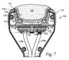
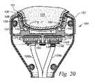
図3は、アプリケータ104の端面図である。図4は、図3のB‐B線矢視断面図である。図5および図6は、図4に対応した断面図であり、取り外し可能なライナ131の取り付け後(図5)および患者100に対して実施された冷却手技中(図6)におけるアプリケータ100を示す図である。図1〜図6をまとめて参照すると、アプリケータ104は、組織受け入れキャビティ132を構成することができ、このアプリケータは、キャビティ132内に伝熱面134を有することができる。伝熱面134は、耐久性のある表面であるのが良く、アプリケータ104は、この耐久性のある表面を通って治療部位105のところの組織135を冷却するよう構成されている。この冷却中、ライナ131および接着剤136が伝熱面134と組織135との間に配置されるのが良い。ライナ131は、例えば、治療中、アプリケータ104を清浄に保つのを助ける上で有用であると言える。以下に詳細に説明する接着剤136は、例えば、伝熱面134と組織135との安定した熱的かつ物理的接触状態を維持する上で有用であると言える。ライナ131は、ライナ接着剤(図示せず)により、アプリケータ104に取り付けられるのが良くかつ/あるいは別の適当な仕方で、例えばアプリケータ104により生じる真空によって定位置に保持されるのが良い。ライナ131と伝熱面134との間にライナ接着剤が存在する場合、かかるライナ接着剤は、接着剤136に関して以下に説明するように何らかの特別な特性、例えば温度依存性の接着剤の接着力および/または粘度を有する必要はない。 FIG. 3 is an end view of the
伝熱面134は、例えばコントローラ124を介して温度制御されるのが良い。図示の実施形態では、伝熱面134は、三次元である。他の実施形態では、伝熱面134は、二次元であるのが良い。図4に示されているように、アプリケータ104は、キャビティ132の本体を構成するカップ137およびキャビティ132の口を構成する異形リップ138を有するのが良い。カップ137は、キャビティ132中に引き込まれた組織135を受け入れるよう輪郭付けられるのが良くかつ組織135の冷却を容易にするためのヒートシンクとしての役目を果たすのが良い。リップ138は、患者の皮膚111に密着するとともに/あるいはライナ131、接着剤136、または伝熱面134と患者の皮膚111との間に設けられた別の介在する構造または物質に密着するよう構成されているのが良い。アプリケータ104は、キャビティ132の最も下方の部分のところにスロット139を有するのが良い。アプリケータ104は、キャビティ132内かつスロット139の周りに側部吸引ポート140および端部吸引ポート142を更に有するのが良い。スロット139、側部吸引ポート140、および端部吸引ポート142は、吸引ライン128d経由でかつアプリケータ104内の追加の吸引ライン(図示せず)経由で吸引システム122に作動可能に連結されるのが良い。図示の実施形態では、アプリケータ104は、アプリケータ104に向いたライナ131の表面に施されたライナ接着剤の使用に加えてまたはこれに代えて、側部および端部吸引ポート140,142のところの吸引力によってライナ131をキャビティ132内に保持するよう構成されている。 The temperature of the
スロット139のところの吸引力は、組織135をキャビティ132中に引き込んでこの組織135を接着剤136の助けによりキャビティ132内に保持するのが良い。以下に説明するように、接着剤の引張り接着力および粘度は、温度の減少につれて増大するのが良く、その結果、接着剤により提供される初期接着力は、比較的弱いのが良い。他の実施形態では、アプリケータ104の対応物は、取り外し可能なライナなしで使用可能に構成されていても良く、側部および端部吸引ポート140,142ならびにスロット139のところの吸引力は、組織135をキャビティ132内に引き込んでこの組織135をキャビティ132内に保持することができる。さらに別の実施形態では、アプリケータ104の対応物は、他の適当な吸引形態を有することができる。さらに、アプリケータ104の対応物は、吸引機能なしであっても良く、例えば、組織135をキャビティ132内に引き込んで組織135をキャビティ132内に保持する場合、かかる対応物は、必要とされない。例えば、実質的に平べったいまたは僅かに湾曲したアプリケータ104の対応物は、吸引力を用いないで患者の皮膚111上に直接置かれてストラップおよび接着剤136だけでまたは接着剤136だけで定位置に保持されるのが良い。 The suction force at
再び図1〜図6を参照すると、アプリケータ104は、スロット139の下に位置する流体冷却要素144を更に有するのが良い。流体冷却要素144は、伝熱面134経由で熱伝達を促進する仕方で伝熱流体を運搬するよう形作られたチャネル146を含むのが良い。アプリケータ104は、供給流体ライン128aおよび戻り流体ライン128bにそれぞれ結合された入口ポート148および出口ポート150を有するのが良い。チャネル146は、入口ポート148と出口ポート150との間で曲がりくねったまたは他の適当な経路に沿って延びるのが良い。アプリケータ104は、流体冷却要素144とスロット139との間に設けられた熱電素子152を更に有するのが良い。流体冷却要素144および熱電素子152は、所望の冷却レベルまたは所望の加熱レベルを生じさせるよう一緒にまたは別々に使用可能である。流体冷却要素144および/または加熱のための熱電素子152を用いることは、例えば、アプリケータ104を冷却手技が完了した後に治療部位から離すのを容易にする上で有用な場合がある。 With reference to FIGS. 1 to 6 again, the
図7〜図9は、図6に類似した断面図であり、本発明の他のそれぞれの実施形態に従って冷却治療中における治療インターフェースの周りの領域を示す図である。特に、図7〜図9は、治療インターフェースのところの互いに異なる接着形態を示している。図7に示されている実施形態では、接着剤136は、ライナ131が皮膚111に接触する前にライナ131に塗布される。したがって、接着剤136は、ライナ131と接触状態にはない治療部位105の部分にはないのが良い。幾つかの場合、接着剤136は、ライナ131上にあらかじめ施される。例えば、ライナ131は、接着剤136の層を備えた状態で包装されるとともに1回使用後に破棄されるよう構成されるのが良い。他の実施形態では、接着剤136は、治療が開始する直前で、例えばライナ131がアプリケータ104に取り外し可能に連結される直前または直後にライナ131に塗布されるのが良い。図8に示されている実施形態では、アプリケータ104は、ライナ131を備えておらず、接着剤136が皮膚111と伝熱面134との間に直接施される。この形態は、例えば、接着剤136を保護することが必要ではない場合、例えば接着剤136が水溶性でありかつ伝熱面134に接着剤136が埋め込み状態になる場合のある隙間および割れ目がない場合に望ましいと言える。これらの場合または他の場合、スロット139、側部吸引ポート140、および端部吸引ポート142は、接着剤136が吸引システム122中に引き込まれるのを阻止するフィルタ(図示せず)を有するのが良い。 7-9 are cross-sectional views similar to FIG. 6 showing the area around the treatment interface during cryotherapy according to each of the other embodiments of the present invention. In particular, FIGS. 7-9 show different bonding morphologies at the treatment interface. In the embodiment shown in FIG. 7, the adhesive 136 is applied to the
図9に示されている実施形態では、接着剤136は、患者の皮膚111とアプリケータ104の伝熱面134との間に配置された吸収性基板160によって担持される。接着剤136と吸収性基板160は、一緒になって、治療インターフェースのところに配置されるよう構成される複合構造体162を構成することができる。吸収性基板160は、例えば、低い粘度での接着剤136の塗布を容易にし、接着剤136を治療面のところの定位置に保持し、アプリケータ104の配置中における接着剤136の変位を減少させまたは阻止するとともに/あるいは連続した材料層がアプリケータ104と患者の皮膚111との間に存在するようにするのに有用であると言える。同様に、連続した材料層がアプリケータ104と患者の皮膚との間に存在するようにすることにより、患者の皮膚111に直接触れるアプリケータ104の部分がないようにすることができる。過冷却治療温度を用いる場合、アプリケータ104と患者の皮膚111とのかかる直接的な接触は、望ましくない場合があり、と言うのは、かかる直接的な接触は、皮膚111に不用意に菌を付けたり皮膚中に時期尚早な凍結事象を生じさせたりする場合があるからである。 In the embodiment shown in FIG. 9, the adhesive 136 is supported by an absorbent substrate 160 disposed between the patient's
幾つかの実施形態では、吸収性基板160を患者の首、腕、脚、胴などの周りにフィットさせることができるよう管状でありかつ伸縮性である。他の実施形態では、吸収性基板160は、平べったいまたは湾曲したパッドであっても良く、あるいは治療部位と最適な接触を行うが当てたり取り外したりするのが容易な他の適当な形態を有しても良い。吸収性基板160は、伸縮性の布、メッシュ、または接着剤136を担持するのに適した他の多孔質材料から成るのが良い。綿、レーヨン、およびポリウレタン生地は、吸収性基板160に用いられるのに適した材料の2、3の例である。さらに、吸収性基板160は、対応の接着剤136の低い熱伝導率を少なくとも部分的に補償する熱伝導性材料を含むのが良い。かくして、幾つかの場合、複合構造体162は、接着剤136単独よりも熱伝導率が高い。高い熱伝導率は、例えば、冷却手技中における凍結事象の熱的シグナチャの検出を容易にするのに有益であると言える。吸収性基板160が伸縮性布を含む場合、この布の繊維の何割かまたは全ては、熱伝導性材料で作られるのが良い。例えば、布は、金属繊維、炭素繊維、および/または熱伝導性被膜を備えた繊維を含むのが良い。炭素繊維は、例えば、カルゴン・カーボン(Calgon Carbon)(ペンシルベニア州ピッツバーグ所在)からFLEXZORB(商標)で入手できる。吸収性基板160のこれらの形態および他の形態は、1回使用または多数回使用向けに構成でき、そして接着剤136があらかじめ塗布された状態でまたは塗布されない状態で包装できる。吸収性基板160に接着剤136があらかじめ塗布されている場合、対応の複合構造体162は、成分としての接着剤136を周囲環境から保護するために不透湿性包装材(図示せず)内に封入されるのが良い。さらに、複合構造体162は、ライナ131とは別個にまたはライナ131と一緒に包装されるのが良い。特定の実施形態では、複合構造体162は、複合構造体162およびライナ131を、複合構造体162を別個に位置決めする必要なく、患者の皮膚111に単に接触させることができるようライナ131上にあらかじめ位置決めされる。別の実施形態では、複合構造体162は、ライナ131と別個独立であってアプリケータ104との熱的および物理的接触を確立する前に、患者の皮膚111上に配置されるよう構成されている。 In some embodiments, the absorbent substrate 160 is tubular and stretchable so that it can be fitted around the patient's neck, arms, legs, torso, and the like. In other embodiments, the absorbent substrate 160 may be a flat or curved pad, or other suitable embodiment that provides optimal contact with the treatment site but is easy to apply and remove. May have. The absorbent substrate 160 may consist of a stretchable cloth, mesh, or other porous material suitable for carrying the adhesive 136. Cotton, rayon, and polyurethane fabrics are just a few examples of suitable materials for use in the absorbent substrate 160. In addition, the absorbent substrate 160 may include a thermally conductive material that at least partially compensates for the low thermal conductivity of the
図10は、図9の一部分の拡大図である。図11は、図10に類似した断面図であり、本発明の別の実施形態に従って治療インターフェースのところの温度センサ164を示す図である。図11に示されているように、温度センサ164は、吸収性基板160によって担持されるのが良い(例えば、これに埋め込まれるのが良い)。変形例として、温度センサ164の対応物は、アプリケータ104の別の適当な部分、例えばアプリケータ104の伝熱面134によって担持されても良い(例えば、これに埋め込まれても良い)。温度センサ164は、例えば、凍結事象と関連した熱エネルギーを検出前に運ばなければならない距離を短くすることによって皮膚111のところでの凍結事象の熱的シグナチャの検出を容易にするのに有用であると言える。温度センサ164は、吸収性基板160から出て外部エレクトロニクスへの接続可能なポート(図示せず)まで延びる電線166を有するのが良い。変形例として、温度センサ164は、外部エレクトロニクスとワイヤレスで通信するよう構成されていても良い。幾つかの場合、温度センサ164は、吸収性基板160中に組み込まれる。他の場合、温度センサ164は、使用時点で吸収性基板160中に挿入される。これらの場合および他の場合、温度センサ164は、1回使用であっても良く、多数回使用であっても良い。 FIG. 10 is an enlarged view of a part of FIG. 9. FIG. 11 is a cross-sectional view similar to FIG. 10 showing a
図12および図13は、互いに異なる形式のアプリケータとの接着剤136の使用法を示している。図12に示されている実施形態では、接着剤136は、治療部位171のところで「ピンチ(pinch)型」アプリケータ170と併用状態で示されている。アプリケータ170は、冷却素子176にそれぞれ作動可能に連結された側壁174を備えたフレーム172を有するのが良い。フレーム172は、端部隙間177を形成することができ、アプリケータ170は、この端部隙間のところに吸引ポート178を有する。端部隙間177のところの吸引力は、組織135の冷却が始まる前に組織135を側壁174相互間で捕捉状態で治療部位171のところに保持するのを容易にすることができる。組織135の冷却が始まった後、接着剤136は、冷えて組織135と側壁174との強固な接着剤結合部を形成することができる。少なくとも幾つかの場合、端部隙間177のところの吸引力は、組織135と側壁174との接着剤結合部が強化された後、減少する。端部隙間177のところの吸引力を減少させることは、例えば、端部隙間177の最も近くに位置する組織135の一部分のところでの吸引力と関連した血液のたまりを減少させまたはなくすのに有用であると言える。本発明の少なくとも幾つかの実施形態に従って接着剤136と併用できる「ピンチ型」アプリケータに関する追加の詳細が例えば米国特許出願公開第2015/0342780号明細書および米国特許出願第14/662,181号明細書に見受けられ、これら2つの特許文献を参照により引用し、これらの記載内容全体を本明細書の一部とする。 12 and 13 show the use of adhesive 136 with different types of applicators. In the embodiment shown in FIG. 12, the adhesive 136 is shown in combination with the "pinch"
図13に示された実施形態では、接着剤136は、アプリケータ104(図6)に類似した別のカップ型アプリケータ179と併用状態で示されている。アプリケータ179もまた、皮膚111とアプリケータ179の伝熱面との間に端部隙間177が存在しないことを除き、アプリケータ170(図12)とほぼ同じである。アプリケータ179は、カップ180およびカップ180の基部のところに設けられていて組織135をカップ180中に完全に引き込む吸引ポート181を有するのが良い。アプリケータ104(図6)およびアプリケータ170(図12)と同様、アプリケータ179は、患者の体から引き離すことができる組織に用いるのに好適な三次元アプリケータである。少なくとも幾つかの場合、これらアプリケータと関連した治療インターフェースもまた、三次元である。しかしながら、理解されるべきこととして、二次元治療インターフェースを介して組織を冷却するアプリケータとも接着剤を使用することができる。 In the embodiment shown in FIG. 13, the adhesive 136 is shown in combination with another cup-
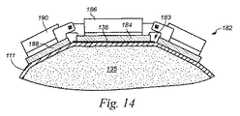
図14に示されている実施形態では、接着剤136は、治療部位183のところで「サドルバッグ型」アプリケータ182と併用状態で示されている。アプリケータ182は、中央裏当て186に結合された冷却要素184を有するのが良い。アプリケータ182は、側方裏当て190にそれぞれ結合された吸引要素188を更に有するのが良い。側方裏当て190は、中央裏当て186の互いに反対側のそれぞれの側部で対応して中央裏当て186にヒンジ式に連結されるのが良い。ストラップ(図示せず)が当初、アプリケータ182を圧縮力によって治療部位183のところに固定するために使用されるのが良い。オプションとして、吸引要素188のところの吸引力は、組織135の冷却が始まる前に組織135を側壁174相互間で捕捉状態で治療部位171のところに保持するのを容易にすることができる。組織135の冷却が始まった後、接着剤136は、冷え、そしてストラップまたは吸引力を引き続き使用することなくアプリケータ182を定位置にほじするのに十分に強固な接着剤結合部を組織135と側壁174との間に形成することができる。少なくとも幾つかの場合、ストラップからの圧縮力および/または吸引要素188からの吸引力を組織135と冷却要素184との接着剤結合部が強化された後に減少させまたはなくすことができる。ストラップからの圧縮力および/または吸引要素188からの吸引力を減少させることは、例えば、患者の快適さを高めるために有用であると言える。本発明の少なくとも幾つかの実施形態に従って接着剤136と併用できる「サドルバッグ(saddlebag )型」アプリケータに関する追加の詳細が例えば米国特許出願公開第2015/0342780号明細書および米国特許出願第14/662,181号明細書に見受けられ、これら2つの特許文献を参照により引用し、これらの記載内容全体を本明細書の一部とする。 In the embodiment shown in FIG. 14, the adhesive 136 is shown in combination with the "saddlebag type"
治療方法Method of treatment
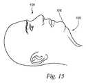
図15〜図18は、本発明の一実施形態に従って治療システム102(図1)を用いて患者100に対して実施される冷却治療中の互いに異なるそれぞれの段階にある患者100の側面図である。図15では、患者100は、治療が始まる前の状態で示されている。図16では、患者100は、接着剤136が粘着性層として治療部位105のところで患者の皮膚111に塗布された後の状態で示されている。接着剤136は、はけ塗りによって、なすり付けによって、配置によって(例えば、接着剤136が吸収性基材によって担持されているとき)、および/または別の適当な塗布技術によって治療部位105のところで皮膚111に塗布されるのが良い。少なくとも幾つかの実施形態では、接着剤136は、塗布温度(例えば、室温または体温)では、皮膚上に安定した粘着性層を形成するのに足るほど高い粘度を有するが、典型的には皮膚に存在する凸凹(例えば、しわ)に容易に適合するのに足るほど低い粘度を有する。例えば、接着剤136を5,000センチポアズから500,000センチポアズの範囲内にあり、例えば10,000センチポアズから100,000センチポアズの範囲内にある粘度で治療部位105のところで皮膚111に塗布するのが良い。加うるに、塗布されるとき、接着剤136は、低い粘着度を有するのが良く、この粘着度は、接着剤が冷却された後実質的に増大する。接着剤136を塗布した後、アプリケータ104を展開するのが良く(図17)、次にこれを動かして治療部位105のところで患者100に接触させるのが良い(図18)。この接触が達成されている間およびこの接触が達成された直後、アプリケータ104を塗布温度では接着剤136の比較的低い粘度および粘着度を考慮して正確に位置決めするのが良い。 15-18 are side views of the
図19および図20は、冷却治療中の互いに異なるそれぞれの段階における図18のC‐C線矢視断面図である。アプリケータ104が最初に治療部位105に接触すると、治療部位105のところの皮膚111および下に位置する組織135は、たいていの場合、キャビティ132の外側に位置するのが良い。図19の矢印192で示されている吸引力が皮膚111および下に位置する組織135をキャビティ132中に引き込むことができ、ついには皮膚111および下に位置する組織135は、動いてアプリケータ104の伝熱面134と熱的かつ物理的接触関係をなす。組織135と伝熱面134との熱的かつ物理的接触関係は、皮膚111を通り、接着剤136を通り、ライナ131を通り、そしてライナ131とアプリケータ104の伝熱面134との間のライナ接着剤(図示せず)を通って延びることができる。接着剤136は、ライナ131経由の皮膚111と伝熱面134との接着力を促進するのに十分であるが、組織135と伝熱面134との間の熱伝導性を甚だしくは減少させないほど薄い厚さで存在するのが良い。少なくとも幾つかの場合、接着剤136は、0.1ミリメートルから1ミリメートルまでの範囲、例えば0.2ミリメートルから0.5ミリメートルまでの範囲にある平均厚さで存在する。特定の実施形態では、接着剤136は、0.3ミリメートルの平均厚さで存在する。 19 and 20 are cross-sectional views taken along the line CC of FIG. 18 at different stages during cryotherapy. When the
皮膚111および下に位置する組織135が最初に動いて伝熱面134と熱的かつ物理的接触関係をなすと、接着剤136は、皮膚111と伝熱面134との弱い接着剤結合部を形成することができる。かくして、少なくとも幾つかの場合、アプリケータ104は、冷却が始まる前に容易に再位置決め可能である。アプリケータ104を再位置決めすることは、例えば、アプリケータ104の初期位置が最適以下である場合に有用であると言える。アプリケータ104をいったん正しく位置決めして組織135と伝熱面134が互いに熱的かつ物理的接触関係(しかもライナ131が存在していない場合でも互いに直接的な物理的接触関係)をなすと、アプリケータ104を起動して熱(図20において矢印194で表わされている)を組織135から引き出すことができる。このように、アプリケータ104は、皮膚111経由で、接着剤136経由で、ライナ131経由で、任意のライナ接着剤経由で、そしてアプリケータ104の伝熱面134経由で組織135を冷却することができる。組織135を冷却している間に接着剤136を冷却することができる。接着剤136を冷却することにより、皮膚111と伝熱面134との直接的なまたは間接的な接着剤結合部を低温で強化することができ、それにより接着剤136経由でかつライナ131経由で皮膚111と伝熱面134との接着力を強化することができる。これは、接着剤136が冷やされている間、皮膚111に対するアプリケータ104の動きを阻みまたは完全に阻止することができる。 When the
皮膚111と伝熱面134との接着剤結合部を低温で強化した後、アプリケータ104は、もはや容易には再位置決め可能ではないと言える。少なくとも幾つかの場合、接着剤136を塗布温度から冷却治療と関連した冷却温度に冷却することにより、皮膚111と伝熱面134との接着剤結合部の引張り強度を少なくとも1.25倍超、1.5倍超、2倍超、3倍超、4倍超、5倍超、6倍超、7倍超、10倍超、20倍超、または30倍超に高めることができる。例えば、接着力を低温で強化するときに伝熱面134に垂直な方向における皮膚111と伝熱面134との接着状態を壊すのに必要な力は、接着力を低温で強化する前に接着関係を壊すのに必要な対応の力の少なくとも1.25倍超、1.5倍超、2倍超、3倍超、4倍超、5倍超、6倍超、7倍超、10倍超、20倍超、または30倍超であるのが良い。同様に、接着剤136を塗布温度から冷却治療と関連した冷却温度に冷却することにより、少なくとも、皮膚111と伝熱面134との接着剤結合部の剪断強度を、剪断強度が低温で強化される前の皮膚111と伝熱面134との接着剤結合部の剪断強度の1.25倍超、1.5倍超、2倍超、3倍超、4倍超、5倍超、6倍超、7倍超、10倍超、20倍超、または30倍超に高めることができる。例えば、接着力を低温で強化するときに伝熱面134に平行な方向における皮膚111と伝熱面134との接着状態を壊すのに必要な力は、接着力を低温で強化する前に接着関係を壊すのに必要な対応の力の少なくとも1.25倍超、1.5倍超、2倍超、3倍超、4倍超、5倍超、6倍超、7倍超、10倍超、20倍超、または30倍超であるのが良い。剪断強度の増大は、冷却治療中における皮膚111と伝熱面134との任意のX、Y軸相対運度を阻止する上で重要な場合がある。 After strengthening the adhesive bond between the
「カップ(cup)型」アプリケータ(例えば、図6に示されているアプリケータ104)または「ピンチ型」アプリケータ(例えば、図12に示されているアプリケータ170)に関し、組織が側壁を有するカップまたはウェル中に引き込まれる場合、剪断強度の増大は、皮膚と伝熱面との相対運動を減少させまたはなくす上で極めて効果的である場合がある。これは、治療部位のところでのこれらアプリケータと皮膚との「ポップオフ(pop off )」または他形式の望ましくないシフト動作または分離を減少させまたはなくす上で有用な場合がある。表面アプリケータ(例えば、図14に示されているアプリケータ182)の場合、Z軸に沿う運動を阻止する引張り強度の増大は、Z軸における皮膚と伝熱メントの相対運動を減少させまたはなくす上で極めて効果的な場合がある。この場合もまた、これは、治療部位のところでのこれらアプリケータと皮膚との「ポップオフ(pop off )」または他形式の望ましくないシフト動作または分離を減少させまたはなくす上で有用な場合がある。 For a "cup" applicator (eg, the
温度変化に応答した接着力および粘度の大きな可逆的変化を示す上述した接着剤の使用に加えて、当業者であれば理解されるように、接着剤吸収剤(用いられる場合)、ライナ(用いられる場合)、伝熱面、および接着剤に接触することができる任意他のコンポーネントを形成するのに用いられる材料であればどんなものでも接着剤と適合性があるはずである。例えば、これら他の構造体および材料は、接着剤に対して好ましくは濡れ状態であって室温ではこれに対して強固な結合部を形成するよう選択されるのが良い。少なくとも1つの試験された接着剤フォーメーションに関し、アルミニウム、綿、レーヨン、およびポリウレタンが強固な接着剤結合部のフォーメーションと適合性のあることが判明した。結合強度は、接着剤を担持した吸収性基材が少なくとも幾分多孔質の表面を有する場合に増大することが判明した。 In addition to the use of adhesives described above, which show large reversible changes in adhesive strength and viscosity in response to temperature changes, as will be appreciated by those skilled in the art, adhesive absorbers (if used), liners (used Any material used to form the heat transfer surface, and any other component that can come into contact with the adhesive, if any) should be compatible with the adhesive. For example, these other structures and materials are preferably selected to form a strong bond to the adhesive, preferably wet and at room temperature. For at least one tested adhesive formation, aluminum, cotton, rayon, and polyurethane were found to be compatible with the strong adhesive joint formation. Bond strength has been found to increase when the absorbent substrate carrying the adhesive has at least a somewhat porous surface.
皮膚111と伝熱面134との接着剤結合部が低温で強化された後、組織135をキャビティ132中に押し込むために当初用いられる吸引力および/または圧縮力のレベルは、キャビティ132内の組織135の位置を維持する上では不必要な場合がある。したがって、吸引力および/または圧縮力のレベルを減少させることができ、このことは例えば、長期間にわたる治療中に患者の快適さを高めるとともに/あるいは吸引力および/または圧縮力の望ましくない副作用を減少させる上で有益な場合がある。幾つかの場合、組織135と伝熱面134との熱的かつ物理的接触状態は、組織135が冷却されている間、主として、接着力によって起こりまたは接着性だけで起こる。他の場合、組織135と伝熱面134との熱的かつ物理的接触状態を維持することは、組織135が冷却されている間、主として、接着力によって補完される吸引力によって起こるのが良い。 After the adhesive bond between the
少なくとも幾つかの実施形態では、接着剤136を塗布温度から冷却治療と関連した冷蔵温度まで冷却することにより、接着剤136の粘度がセンチポアズ尺度で少なくとも1,000%(例えば少なくとも10,000%)増大する。これらの実施形態および他の実施形態では、接着剤136をこのように冷却することにより、接着剤136は、接着剤136のガラス転移温度よりも高い温度では3,000,000センチポアズから接着剤136の最大粘度までの範囲にある粘度を有することができる。接着剤136をそのガラス転移温度よりも低い温度まで冷却することにより、接着剤136を介する皮膚111と伝熱面134との間の接着力を弱くすることができる。したがって、接着剤136は、冷却治療中に接着剤136を冷却する目標である最も低い温度よりも低いガラス転移温度を有するよう選択されるのが良い。例えば、接着剤136は、−20℃よりも低い、例えば−30℃よりも低いガラス転移温度を有するよう選択されるのが良い。 In at least some embodiments, by cooling the adhesive 136 from the coating temperature to the refrigeration temperature associated with cryotherapy, the viscosity of the adhesive 136 is at least 1,000% (eg, at least 10,000%) on the centipores scale. Increase. In these and other embodiments, by thus cooling the adhesive 136, the adhesive 136 is charged from 3,000,000 centipoise to the adhesive 136 at a temperature higher than the glass transition temperature of the adhesive 136. Can have viscosities in the range up to the maximum viscosity of. By cooling the adhesive 136 to a temperature lower than the glass transition temperature, the adhesive force between the
特定の実施形態によれば、室温でまたは別の適当な塗布温度では、接着剤136は、アプリケータ104を皮膚111上に容易に置いたり取り外したりすることができ、そしてアプリケータ104を正しく位置決めするための必要に応じて側方に動かしまたはねじることができるよう最小接着力を有する。例えば、冷却前の接着力は、アプリケータ104を正確な位置に保ち、そして他の何らかの保持力を用いないで相当長い期間にわたってその位置に固定したままにするのには不十分な場合がある。しかしながら、治療温度では、接着力は、他の何らかの取り付け力を用いないで接着力だけでアプリケータ104を定位置に保つのに足るほど強力であるように劇的に増大する。不必要になる場合のある他の取り付け力としては、吸引力、ストラップ、またはそれどころか重力の助けによる患者の組織135の支持(例えば、患者100が横になっていてかつアプリケータ104が患者100の上に乗っかっている場合)を含む場合がある。換言すると、接着剤136は、アプリケータ104を任意の向きで定位置に固定するのに足るほど強固である。したがって、患者100が立っていてアプリケータ104が患者100から、例えば患者の腹部または脇腹から単にぶら下がっている場合であっても、接着剤136は、アプリケータ104を固定するとともにこれを定位置にかつアプリケータ104によって治療を受けている治療部位のところでは皮膚111に対して動かないように保つに足るほど強固である。さらに、接着剤136は、アプリケータ104を定位置に保持するとともに患者が立っていてかつアプリケータ104が患者からぶら下がっている場合、アプリケータ104が患者の皮膚111に対して動くのを阻止するのに足るほど強固であるだけでなく、患者が動き、揺れ、あるいは急に立ち上がったり飛び降りたりする場合であっても上述のように強固であることができる。 According to certain embodiments, at room temperature or at another suitable coating temperature, the adhesive 136 allows the
図21は、図20の一部分の拡大図である。図21に示されているように、ライナ131は、スロット139の周囲のところに位置する丸形縁部196を有するのが良い。図20および図21を一緒に参照すると、接着剤136が皮膚111とライナ131との間から絞り出され、それによりスロット139に向かって、リップ138の上方の領域に向かってかつ/あるいはライナ131が存在していない他の領域に向かってずらされるのが良い。例えば、接着剤136は、スロット139から見て遠くに位置する丸形縁部196の側部のところよりもスロット139の近くに位置する丸形縁部196の側部のところの方が厚いのが良い。接着剤136は、塗布時、これがライナ131にしっかりと圧接された治療部位105の領域から全く絞り出されることはないほど高い粘度を有するのが良い。接着剤136は、図示の実施形態では、患者の皮膚111をライナ131に接触させる前に患者の皮膚111に塗布されるので、接着剤136は、ライナ131と接触状態にはない治療部位105の部分、例えばスロット139のところの治療部位105の一部分のところに存在するのが良い。接着剤136は、塗布時、これをライナ131と接触状態にはない治療部位105の部分のところの吸引力によって皮膚111から引き離されないほど高い粘度を有するのが良い。しかしながら、幾つかの場合、治療部位105のこれらの部分のところの接着剤136の何割かまたは全ては、吸引力によって皮膚111から引き離されるのが良い。これらの場合、アプリケータ104は、遊離した接着剤136が引き込まれる吸引ラインおよび/またはポートの詰まりを減少させまたはなくすフィルタ(図示せず)を有するのが良い。 FIG. 21 is an enlarged view of a part of FIG. 20. As shown in FIG. 21, the
図22は、本発明の一実施形態に従って患者の組織領域を冷却する方法200を説明した流れ図である。説明を簡単にするために、主としてアプリケータ104に関してこの方法200について更に説明する。しかしながら、理解されるべきこととして、本発明の実施形態に従って、この方法200(適当な場合)および/またはこの方法200の諸部分(適当な場合)をアプリケータ104,170,179,182または他のアプリケータのうちの任意のものに関して実施することができる。図20〜図22および上述した種々の先の図を一緒に参照すると、方法200は、皮膚111とアプリケータ104を接着剤136がこれらの間に位置した状態で互いに接触させるステップを含むのが良い(ブロック202)。上述したように、これは、接着剤136を皮膚111上に、ライナ131上に、かつ/あるいはアプリケータ104の伝熱面134上に塗布する(例えば、刷毛塗りする、なすり付ける、配置するなど)ステップ、および次に皮膚111とアプリケータ104を互いに熱的かつ物理的接触状態にするステップを含むのが良い。接着剤136は、別個独立であっても良くあるいは吸収性基材(例えば図9に示されている吸収性基材160)によって担持されても良い。少なくとも幾つかの実施形態では、方法200は、皮膚111をキャビティ132中に押し込むステップを含む(ブロック204)。例えば、方法200は、皮膚111を吸引力によって少なくとも部分的にかつ/あるいは圧縮力によって少なくとも部分的にキャビティ132中に押し込むステップを含むのが良い。 FIG. 22 is a flow chart illustrating a
組織135が皮膚111経由でかつ接着剤136経由で伝熱面134と熱的かつ物理的接触状態にあるとき、方法200は、接着剤136を冷却するステップ(ブロック206)および組織135を冷却するステップ(ブロック208)を含むのが良い。接着剤136を冷却するステップは、接着剤136を接着剤136のガラス転移温度よりも低い温度、例えば接着剤136のガラス転移温度よりも1℃高い温度から接着剤136のガラス転移温度よりも10℃高い温度まで、例えば1℃、2℃、3℃、4℃、5℃、6℃、7℃、8℃、9℃、または10℃のうちのいずれかだけ高い温度まで冷却するステップを含むのが良い。少なくとも幾つかの場合、接着剤136を冷却する目標である温度は、−25℃から−1℃まで、−25℃から−5℃まで、−20℃から−8℃まで、または−18℃から−10℃までのいずれかの範囲内にある。接着剤136を冷却することにより、皮膚111と伝熱面134との接着剤結合部を低温で強化することができる。組織135を冷却することは、接着剤結合部の低温強化中にかつ/あるいは接着剤結合部の低温強化後に起こるのが良い。組織135を冷却することは、接着剤136の粘着性層経由で、吸収性基材160および接着剤136を含む複合構造体経由で(図9)かつ/あるいはアプリケータ104と皮膚111との間の塗布向きの別の適当な形態をなす接着剤136経由で組織135を冷却するステップを含むのが良い。少なくとも幾つかの実施形態では、組織135は、皮下の脂質に富んだ細胞および/または皮膚または皮下層中の任意他の標的構造を損傷させまたは違ったやり方で崩壊させるのに十分に低い温度まで冷却される。これらの実施形態および他の実施形態では、組織135を冷却することは、組織135を0℃、−5℃、−10℃よりも低い温度までまたは少なくとも15分間、別の適当なしきい値よりも低い温度まで冷却するステップを含むのが良い。 When the
組織135を冷却している間、方法200は、組織135と伝熱面134との熱的かつ物理的接触状態を維持するステップを含むのが良い(ブロック210)。接着剤136により、この熱的かつ物理的接触状態は、接着剤136が存在していなかった場合よりも信頼性が高い状態になることができる。少なくとも幾つかの場合、皮膚111と伝熱面134との接着剤結合部は、組織135を冷却している間、組織135をキャビティ132中に押し込むために用いられる吸引力および/または圧縮力に少なくとも部分的にまたは全体が取って代わるに足るほど強固になるのが良い。これらの場合または他の場合、方法200は、接着剤結合部を低温で強化した後かつ組織135を冷却している間、吸引力および/または圧縮力を減少させまたはゼロにするステップを含むのが良い。方法200は、組織135を冷却している間、ライナ131の一部分をキャビティ132内に維持するステップを更に含むのが良い(ブロック212)。例えば、キャビティ132内のライナ131の位置は、少なくとも主として、吸引力によってかつ/あるいは任意特定の特性を有する必要がないに過ぎない別の接着剤によって維持されるのが良い。皮膚111と伝熱面134との強固な接着剤結合部が接着剤136経由で存在している間、組織135をアプリケータ104から迅速に離す場合、ライナ131をキャビティ132内に保持する吸引力を解除するのが良く、そして組織135をライナ接着剤が存在していない場合、ライナ131と一緒にキャビティ132から取り出すのが良い。ライナ接着剤が存在しているときであってまたはライナ131が用いられない場合であってアプリケータ104からの組織135の迅速な解除が必要な場合、アプリケータ104を迅速に再加温して、組織135をキャビティ132から容易に取り出すことができるのに足るほど高い温度まで接着剤136を加温するのが良い。 While cooling the
図22に示されているように、方法200は、接着剤136を冷却した後、接着剤136を加温するステップ(ブロック214)を更に含むのが良い。これは、皮膚111と伝熱面134との接着力を弱くすることができる。少なくとも幾つかの実施形態では、接着剤136を加温するステップは、接着剤136を少なくとも10℃だけ加温するステップを含む。さらに、接着剤136を加温するステップは、接着剤136を能動的に加温するステップ(例えば、熱電素子152を用いて)および/または接着剤136を受動的に加温するステップ(例えば、非冷却伝熱流体を流体冷却要素144に通すことによって)を含むのが良い。接着剤136を加温することにより、接着剤136の粘度を1,000,000センチポアズ未満に減少させることができる。接着剤136を加温した後、方法200は、皮膚111と伝熱面134を分離するステップを含むのが良い(ブロック216)。 As shown in FIG. 22, the
本発明の少なくとも幾つかの実施形態による冷却治療を用いると、皮膚、皮下層または他の層のいずれかの中の標的組織を減少させまたはなくし、それにより組織が所望の外観を有することができるようにする。例えば、本発明の実施形態としての治療システムは、医学的処置を実施して治療効果および/または美容手技を提供して美容的に有益な効果を得ることができる。理論に束縛されるものではないが、冷却の選択的作用は、結果として、例えば、細胞膜の崩壊、細胞収縮、無効化、崩壊、損傷、破壊、除去、殺傷、減少および/または脂質に富んだ細胞および脂質に富んでいない細胞の他の変更方法、皮膚中の他の組織、皮下の組織または他の組織の変更をもたらすと考えられる。このような変更は、単独または組合せで作用する1つまたは2つ以上の機序から生じると考えられる。このような1つまたは複数の機序は、アポトーシスカスケードをトリガし、これは、非侵襲的冷却による脂質に富んだ細胞死の顕著な形態であると考えられる。これらの実施形態のうちの任意の実施形態において、組織冷却効果は、所望の作用機構、例えばアポトーシス、リポリシスなどによって脂質に富んだ細胞の選択的減少であるのが良い。幾つかの手技では、アプリケータ104は、患者の標的組織を約−25℃から約20℃までの範囲の温度まで冷却することができる。他の実施形態では、冷却温度は、約−20℃〜約10℃、約−18℃〜約5℃、約−15℃〜約5℃、または約−15℃〜約0℃であるのが良い。別の実施形態では、冷却温度は、−5℃以下、−10℃以下、−15℃以下であるのが良く、あるいは、さらに別の実施形態では、約−15℃〜約−25℃であるのが良い。他の冷却温度および温度範囲を用いることができる。 Cryotherapy according to at least some embodiments of the invention can be used to reduce or eliminate target tissue in any of the skin, subcutaneous layers or other layers, whereby the tissue can have the desired appearance. To do so. For example, a therapeutic system as an embodiment of the present invention can perform a medical procedure to provide a therapeutic effect and / or a cosmetological procedure to obtain a cosmetically beneficial effect. Without being bound by theory, the selective action of cooling is, as a result, rich in cell membrane disruption, cell contraction, nullification, disruption, damage, destruction, removal, killing, reduction and / or lipid. Other methods of altering cells and non-lipid-rich cells are thought to result in alterations of other tissues in the skin, subcutaneous tissues or other tissues. Such changes are believed to result from one or more mechanisms that act alone or in combination. One or more such mechanisms trigger an apoptotic cascade, which is believed to be a prominent form of lipid-rich cell death due to non-invasive cooling. In any of these embodiments, the tissue cooling effect is preferably a selective reduction of lipid-rich cells due to the desired mechanism of action, such as apoptosis, lipolysis, and the like. In some procedures, the
「プログラムされた細胞死」とも称されるアポトーシスは、周囲組織にダメージを及ぼすことなく細胞が自爆するという遺伝学的に誘起される死のメカニズムである。順序付けされた一連の生化学的事象は、細胞に形態学的変化を誘起させる。これらの変化は、細胞の泡状突起、細胞膜の非対称性および取り付けのロス、細胞収縮、クロマチンの凝縮、および染色体DNA分裂を含む。低温露出(cold exposure)のような外部刺激による傷は、細胞に細胞アポトーシスを誘起することのできる1つの機序である。これについては、ダブリュー・エー・ネーグル(Nagle, W. A.),ビー・エル・ソロフ(Soloff, B. L.),エー・ジェー・モス・ジュニア(Moss, A. J. Jr.),「カルチャード・チャイニーズ・ハムスター・セルズ・アンダーゴー・アポトーシス・アフター・エクスポージャ・トゥ・コールド・バット・ノンフリージング・テンプリチャーズ(Cultured Chinese Hamster Cells Undergo Apoptosis After Exposure to Cold but Nonfreezing Temperatures)」,クライオバイオロジー(Cryobiology),1990年,第27巻,p.439〜451を参照されたい。 Apoptosis, also known as "programmed cell death," is a genetically induced mechanism of death in which cells self-destruct without damaging surrounding tissues. A series of ordered biochemical events induces morphological changes in cells. These changes include cell foaming, cell membrane asymmetry and loss of attachment, cell contraction, chromatin condensation, and chromosomal DNA division. Injury caused by external stimuli, such as cold exposure, is one mechanism that can induce cell apoptosis in cells. For more on this, W. A. Nagle (Nagle, WA), B. L. Solof (Soloff, BL), AJ Moss Jr. (Moss, AJ Jr.), "Cultured Chinese Hamster Sels." Undergo Apoptosis After Exposure to Cold but Nonfreezing Temperatures, Cryobiology, 1990, No. Volume 27, p. See 439-451.
細胞壊死(局部的な炎症を生じる細胞死のトラウマ形態)とは対照的なアポトーシスの一観点は、アポトーシス細胞が細胞膜の表面に食作用マーカを表現および表示し、従って、食作用に対する細胞をマクロファージによってマークすることである。その結果、食細胞は、免疫応答を引き出すことなく、死につつある細胞(例えば、脂質に富んだ細胞)を吸収して除去することができる。脂質に富んだ細胞にこれらのアポトーシス事象を引き出す温度は、皮下脂肪組織の長期持続および/または永久的減少および再整形に貢献することができる。 One aspect of apoptosis, as opposed to cell necrosis (the traumatic form of cell death that causes local inflammation), is that apoptotic cells express and display phagocytotic markers on the surface of the cell membrane, thus macrophaging cells for phagocytosis. Is to mark by. As a result, phagocytes can absorb and eliminate dying cells (eg, lipid-rich cells) without eliciting an immune response. The temperature that elicits these apoptotic events in lipid-rich cells can contribute to long-term persistence and / or permanent reduction and reshaping of the panniculus adipos.
冷却によるアポトーシスの脂質に富んだ細胞死の1つの機序は、非脂質に富んだ細胞に結晶化を誘起しない温度において脂肪細胞内に脂質の局部的結晶化を伴うと考えられる。結晶化された脂質は、これらの細胞を選択的に傷付け、アポトーシスを誘起することがある(また、結晶化された脂質が脂肪細胞の二脂質膜を損傷または破壊する場合には壊死も誘起することがある)。傷付ける別のメカニズムは、細胞の二脂質膜内におけるこれら脂質の脂質相遷移を伴い、これは、膜を破壊して、アポトーシスを誘起させる。このメカニズムは、多数の細胞形式について記録が詳細に文書に残されており、脂肪細胞または脂質に富んだ細胞が冷却されたときにアクティブとなる。これについては、ピー・マズロー(Mazur, P.),「クライオバイオロジー:ザ・フリージング・オブ・バイオロジカル・イステムズ(Cryobiology: the Freezing of Biological Systems)」,サイエンス(Science),1970年,第68巻,p.939〜94、ピー・ジェイ・クイン(Quinn, P. J.),「ア・リピッド・フェーズ・セパレーション・モデル・オブ・ロー・テンプリチャ・ダメージ・トゥ・バイオロジカル・メンブレンズ(A Lipid Phase Separation Model of Low Temperature Damage to Biological Membranes)」,クライオバイオロジー(Cryobiology )1985年,第22巻,p.128〜147、ビー・ルビンスキー(Rubinsky, B.),「プリンシパルズ・オブ・ロー・テンプリチャー・プリザベーション(Principles of Low Temperature Preservation)」,ハート・フェイリュア・レビューズ(Heart Failure Reviews),2003年,第8巻,p.277〜284を参照されたい。 One mechanism of lipid-rich cell death for cooling-induced apoptosis is thought to be associated with local crystallization of lipids within adipocytes at temperatures that do not induce crystallization in non-lipid-rich cells. Crystallized lipids can selectively damage these cells and induce apoptosis (and also induce necrosis if the crystallized lipids damage or destroy the dilipid membrane of adipocytes. Sometimes). Another mechanism of injury involves the lipid phase transition of these lipids within the cell's bilipid membrane, which disrupts the membrane and induces apoptosis. This mechanism is well documented for a number of cell types and becomes active when adipocytes or lipid-rich cells are cooled. For more on this, Mazur, P., "Cryobiology: the Freezing of Biological Systems," Science, 1970, 68th Volume, p. 939-94, Quinn, PJ, "A Lipid Phase Separation Model of Low Temperature" Damage to Biological Membranes) ”, Cryobiology, 1985, Vol. 22, p. 128-147, Rubinsky, B., "Principles of Low Temperature Preservation", Heart Failure Reviews, 2003 Year, Volume 8, p. See 277-284.
米国特許第8,192,474号明細書に記載されている脂肪細胞損傷の考えられる機序は、かかる細胞が本命債において説明されているように冷却されたときにある特定の条件下で起こる場合のある虚血/再灌流外傷に関連している。例えば、本明細書において説明するような冷却による治療中、標的脂肪組織は、血液供給の際に絞りを受ける場合があり、かくして、加えられた圧力、冷却組織中の血管収縮に影響を及ぼす場合のある冷却などの結果としての隔離に起因して酸素が欠乏する場合がある。酸素欠乏および絞られた血流の期間中における組織中の代謝廃棄物の蓄積によって生じる虚血損傷に加えて、冷却治療後における血流の回復は、さらに、虚血期間を生じた組織に酸素化血液が元通りに流されると起こることが知られている炎症および酸化による損傷に起因して脂肪細胞に対して再灌流外傷を生じさせる場合がある。この種の外傷は、脂肪細胞をエネルギー源に当てることによって(例えば、熱的手段、電気的手段、化学的手段、機械的手段、音響的手段、または他の手段によって)または本明細書において説明するように冷却治療と関連してまたは冷却治療後に血流量を増大させることによって促進される場合がある。例えば種々の機械的手段によって(例えば、圧力を加えることによりまたはマッサージを施すことにより)、化学的手段によってまたはある特定の冷却条件によって、ならびに脂肪組織中の炎症および/または白血球の活動を刺激するための酸素ラジカル形成化合物を局所的に導入することによってかかる脂肪組織中の血管収縮を増大させることもまた、かかる細胞に対する外傷の促進の一因となる場合がある。外傷の他のまだ解明されていない機序が存在する場合がある。 The possible mechanism of adipocyte injury described in U.S. Pat. No. 8,192,474 occurs under certain conditions when such cells are cooled as described in the favorite bond. It may be associated with ischemia / reperfusion trauma. For example, during treatment with cooling as described herein, the target adipose tissue may be squeezed during blood supply, thus affecting the applied pressure, vasoconstriction in the cooling tissue. Oxygen may be deficient due to isolation as a result, such as cooling. In addition to ischemic damage caused by oxygen deficiency and accumulation of metabolic waste in tissues during periods of squeezed blood flow, recovery of blood flow after cooling treatment further oxygenates the tissues that have undergone the ischemic period. Reperfusion trauma to fat cells may occur due to inflammation and oxidative damage known to occur when chemized blood is reconstituted. This type of trauma is described herein by exposing fat cells to an energy source (eg, by thermal, electrical, chemical, mechanical, acoustic, or other means). It may be promoted in connection with cryotherapy or by increasing blood flow after cryotherapy. Stimulates inflammation and / or leukocyte activity in adipose tissue, for example by various mechanical means (eg, by applying pressure or by massaging), by chemical means or by certain cooling conditions. Increasing vascular constriction in such adipose tissue by locally introducing an oxygen radical-forming compound for such cells may also contribute to the promotion of trauma to such cells. There may be other unexplained mechanisms of trauma.
脂質リッチ細胞死に関するアポトーシスメカニズムに加えて、局部的低温露出も、脂質リッチ細胞の脂質分解(すなわち、脂肪代謝)を誘起すると考えられ、皮下の脂質に富んだ細胞の減少を更に増やすように働く既存の脂質分解を増強することが示されている。これについては、エー・エル・バレランド(Vallerand, A. L.),ジェイ・ザメクニック(Zamecnik. J.),ピー・ジェイ・エイチ・ジョーンズ(Jones, P. J. H.),アイ・ジェイコブス(Jacobs, I),「コールド・ストレス・インクリーシズ・リポリシス,FFA RaアンドTG/FFAサイクリング・イン・ヒューマンズ(Cold Stress Increases Lipolysis, FFA Ra and TG/FFA Cycling in Humans)」,アビエーション、スペース・アンド・エンバイロメンタル・メディスン(Aviation, Space and Environmental Medicine),1999年,第70巻,p.42〜50を参照されたい。 In addition to the apoptosis mechanism for lipid-rich cell death, local cold exposure is also thought to induce lipid degradation (ie, fat metabolism) in lipid-rich cells and acts to further increase the loss of subcutaneous lipid-rich cells. It has been shown to enhance existing lipid degradation. For more on this, AL Valerand, AL, Zamecnik. J., Jones, PJH, Jacobs, I, "Cold." Cold Stress Increases Lipolysis, FFA Ra and TG / FFA Cycling in Humans, Aviation, Aerospace Medicine, FFA Ra and TG / FFA Cycling in Humans, Aviation, Space and Humans. Environmental Medicine), 1999, Vol. 70, p. See 42-50.
上記技術の予想される一利点は、標的組織中の皮下の脂質に富んだ細胞を全体として減少させることができ、この場合、同一領域中の脂質に富んでいない細胞に対する付随的な損傷をもたらさないということにある。一般に、脂質に富んでいない細胞に悪影響を及ぼさない低い温度で脂質に富んだ細胞に影響を及ぼすことができる。その結果、脂質に富んだ細胞、例えば高い局在性の脂肪組織(例えば、オトガイ下脂肪過多所、下顎下脂肪過多所、顔面脂肪過多所など)と関連した脂質に富んだ細胞に影響を及ぼすことができる一方で、全体として同一中の脂質に富んでいない細胞(例えば、筋細胞)に損傷を及ぼさない。影響を受けなかった脂質に富んでいない細胞は、脂質に富んだ細胞(例えば、皮下脂肪層よりも深いところに位置する細胞)の下に、真皮中に、表皮中にかつ/あるいは他の場所に位置することができる。 One promising advantage of the technique is that it can reduce subcutaneous lipid-rich cells in the target tissue as a whole, resulting in concomitant damage to non-lipid-rich cells in the same region. There is no such thing. In general, it can affect lipid-rich cells at low temperatures that do not adversely affect non-lipid-rich cells. As a result, it affects lipid-rich cells, such as lipid-rich cells associated with highly localized adipose tissue (eg, submandibular fat hyperplasia, submandibular fat hyperplasia, facial fat hyperplasia, etc.). While it can, it does not damage non-lipid-rich cells (eg, muscle cells) in the same as a whole. Unaffected non-lipid-rich cells are under lipid-rich cells (eg, cells located deeper than the subcutaneous fat layer), in the dermis, in the epidermis, and / or elsewhere. Can be located in.
幾つかの手技では、治療システムは、上側の組織層を通って下に位置する組織から熱を除去することができ、そして最も低い温度がアプリケータの1つまたは複数の冷却面の近くに位置した状態で(すなわち、皮膚の上側層の温度は、標的とされている下に位置する細胞の温度よりも低いのが良い)温度勾配を生じさせることができる。標的細胞の温度をこれら標的細胞に対して破壊的であるのに足るほど低く減少させる(例えば、アポトーシス、細胞の死などを誘起させる)一方で、上側および表面の皮膚細胞の温度を保護状態(例えば、非破壊的)であるようにするのに足るほど高く維持することは、難題である場合がある。これら2つのしきい値相互間の温度差は、小さい場合がある(例えば、約5℃〜約10℃、10℃未満、15℃未満など)。上に位置する細胞(例えば、典型的には水分に富んだ真皮および表皮皮膚細胞)を低温への持続性の暴露を必要とする皮膚科学的手技および関連美容的手技中、凍結による損傷から保護することは、例えばかかる凍結による損傷を阻みまたは阻止するための凍結保護剤を用いることによってこれら皮膚細胞の凍結耐性および/または凍結回避を向上させることを伴うことができる。少なくとも幾つかの場合、接着剤136は、かかる凍結保護剤として作用する。接着剤は、組織が組織の凍結点よりも高い温度まで冷却される場合、凍結が過冷却に起因して起こることのない場合に組織の凍結点よりも低い温度まで組織が冷却される場合に使用でき、あるいは変形例として、組織の凍結が意図されてこれが起こるようになっている手技において使用できる。本発明の少なくとも幾つかの実施形態と適合性のある凍結保護剤に関する追加の詳細は、例えば、米国特許出願公開第2005/0251120号明細書に見受けられ、この米国特許出願公開を参照により引用し、その記載内容全体を本明細書の一部とする。 In some procedures, the treatment system can remove heat from the underlying tissue through the upper tissue layer, and the lowest temperature is located near one or more cooling surfaces of the applicator. In this state (ie, the temperature of the upper layer of skin should be lower than the temperature of the underlying cells being targeted) can produce a temperature gradient. It reduces the temperature of target cells low enough to be destructive to these target cells (eg, induces apoptosis, cell death, etc.) while protecting the temperature of upper and surface skin cells (eg, inducing apoptosis, cell death, etc.). Keeping high enough to be non-destructive, for example) can be a challenge. The temperature difference between these two thresholds may be small (eg, about 5 ° C to about 10 ° C, less than 10 ° C, less than 15 ° C, etc.). Protects underlying cells (eg, typically water-rich dermal and epidermal skin cells) from freezing damage during dermatological and related cosmetic procedures that require sustained exposure to low temperatures This can be accompanied by improving the freeze resistance and / or freeze avoidance of these skin cells, for example by using a cryoprotectant to prevent or prevent such freezing damage. In at least some cases, the adhesive 136 acts as such a cryoprotectant. Adhesives are used when the tissue is cooled to a temperature above the tissue freezing point, when the tissue is cooled to a temperature below the tissue freezing point if freezing does not occur due to supercooling. It can be used, or as a variant, in procedures where tissue freezing is intended and this occurs. Additional details regarding cryoprotectants that are compatible with at least some embodiments of the invention can be found, for example, in US Patent Application Publication No. 2005/0251120, which is cited by reference. , The entire description thereof is a part of the present specification.
接着剤配合内容Adhesive content
本発明の実施形態による接着剤(例えば、上述の接着剤136)は、冷却時に粘度および粘着度(すなわち、粘着性)が著しく増大する結合剤を含むのが良い。接着剤は、結果的に得られる接着剤の粘度温度依存性を変更し、結果的に得られる接着剤の粘着度温度依存性を変更するとともに/あるいは結果的に得られる接着剤のガラス転移温度を低下させるよう結合剤と混ぜ合わされる粘度降下剤を更に含むのが良い。図23は、純粋な結合剤(右側)および粘度降下剤で希釈された結合剤(左側)に関する粘度と温度の関係を表わすプロット図である。図23に示されているように、粘度降下剤を添加することにより、接着剤のガラス転移温度が低下するとともに接着剤に関する高い温度依存性粘度の領域がシフトされて−20℃〜20℃になる。幾つかの場合、結合剤は、室温では固体であり、粘度降下剤は、室温では液体溶剤であり、結合剤について比較的高い溶解限度、例えば50%w/wを超え、60%w/wを超え、70%w/wを超えまたはこれよりも高いしきい値を有する。他の場合、粘度降下剤および結合剤は、室温では混和性液体であるのが良い。 The adhesive according to an embodiment of the present invention (eg,
接着剤中の結合剤と粘度降下剤の相対的な比率は、接着剤の粘度および粘着度が著しく増大する冷却温度範囲が、接着剤が用いられるべき治療の冷却温度範囲に対応するよう選択されるのが良い。標的温度範囲は、例えば、塗布温度(例えば、室温または体温)から皮下の脂質に富んだ細胞および/または皮膚または皮下層中の任意他の標的構造を損傷させまたは違ったやり方で壊すのに適した冷却温度(例えば、−20℃、−15℃、−10℃、または−5℃)まで延びるのが良い。追加的にまたは代替的に、接着剤中の結合剤と粘度降下剤の相対的比率は、粘度降下剤中における結合剤の溶解限度に基づいて選択されても良い。例えば、接着剤中の結合剤の濃度は、接着剤の通常の貯蔵および使用中、結合剤の再結晶化を依然として適切に抑制する最大濃度であるように選択されるのが良い(それにより、接着剤の粘度および粘着度が最大になる)。 The relative ratio of binder to viscosity reducer in the adhesive is selected so that the cooling temperature range in which the viscosity and stickiness of the adhesive increases significantly corresponds to the cooling temperature range of the treatment in which the adhesive should be used. It is good to have. The target temperature range is suitable, for example, to damage or otherwise disrupt subcutaneous lipid-rich cells and / or any other target structure in the skin or subcutaneous layer from the application temperature (eg, room temperature or body temperature). It is preferable to extend to the cooling temperature (for example, -20 ° C, -15 ° C, -10 ° C, or -5 ° C). Additional or alternative, the relative ratio of binder to viscosity-lowering agent in the adhesive may be selected based on the dissolution limit of the binder in the viscosity-lowering agent. For example, the concentration of the binder in the adhesive may be selected to be the maximum concentration that still adequately suppresses the recrystallization of the binder during normal storage and use of the adhesive (thus. Maximum adhesive viscosity and adhesiveness).
本発明の少なくとも幾つかの実施形態による接着剤は、20℃で500,000センチポアズ未満(例えば、5,000センチポアズから500,000センチポアズまでの範囲内にある)粘度および−15℃では、3,000,000センチポアズを超える粘度を有する。これらの場合および他の場合、−10℃における接着剤の粘度は、20℃における接着剤の粘度のセンチポアズ尺度で少なくとも1,000%だけ(例えば、少なくとも3,000%だけ、少なくとも5,000%だけ、または少なくとも10,000%だけ)高いのが良い。さらに、接着剤は、20℃におけるヒトの皮膚に対する第1の引張り接着力レベルおよび第1の引張り接着力レベルの1.25倍超、1.5倍超、2倍超、3倍超、4倍超、5倍超、6倍超、7倍超、10倍超、20倍超、または30倍超の−10℃におけるヒトの皮膚に対する第2の引張り接着力レベルを有するのが良い。ヒトの皮膚に対するこの引張り接着力を試験するには、通常の引張り力をアプリケータと皮膚類似物との間に挟んだ扁平な接着剤層に加えるのが良い。 The adhesive according to at least some embodiments of the present invention has a viscosity of less than 500,000 centipores at 20 ° C. (eg, in the range of 5,000 to 500,000 centipores) and 3, at -15 ° C. It has a viscosity exceeding 1,000,000 centipores. In these and other cases, the viscosity of the adhesive at -10 ° C is at least 1,000% on the centipore scale of the viscosity of the adhesive at 20 ° C (eg, at least 3,000%, at least 5,000%). Only, or at least 10,000%) higher. In addition, the adhesive is more than 1.25 times, more than 1.5 times, more than 2 times more than 3 times and 4 times the first tensile adhesive force level and the first tensile adhesive force level to human skin at 20 ° C. It is preferable to have a second tensile adhesive force level to human skin at −10 ° C. of more than double, more than 5 times, more than 6 times, more than 7 times, more than 10 times, more than 20 times, or more than 30 times. To test this tensile adhesive force to human skin, normal tensile force should be applied to the flat adhesive layer sandwiched between the applicator and the skin analog.
結合剤は、改質または非改質単糖類であるのが良い。これら化合物は、この用途に好適であるといえ、と言うのは、これら化合物は、これらのガラス転移温度を超える温度まで冷却されると、粘度が増大するとともに粘着度が増大するようになる傾向があるからである。上述したように、この挙動は、アプリケータを用いて皮下の脂質に富んだ細胞および/または皮膚または皮下層中の任意他の標的構造を冷却し、それにより損傷させ、または違ったやり方で壊す段階を含む冷却治療中、皮膚とアプリケータとの接着度を高めるのに望ましい。皮膚とアプリケータとの結合強度は、高い粘度(例えば、結合部の内部健全性を維持するため)と高い粘着度(例えば、接着剤と皮膚との結合インターフェースの健全性を維持するため)の両方から恩恵を受けることができる。単糖類はまた、生体適合性であり、非毒性であり、しかも水溶性である傾向があり、後者は、洗浄を容易にするのに有用である。本発明の少なくとも幾つかの実施形態としての方法に用いるのに適した単糖類の例としては、改質および非改質単糖類(例えば、ブドウ糖および果糖)および改質および非改質二糖類(例えば、スクロース、マルトース、およびトレハロース)が挙げられる。ブドウ糖、果糖、およびスクロースアセテートイソブチレン(SAIB)に関する実験データを後述するが、理解されるべきこととして、他の改質および非改質単糖類もまた、本発明の実施形態としての方法に使用するのに適していることが見込まれる。 The binder is preferably a modified or unmodified monosaccharide. These compounds are suitable for this application, because when they are cooled to temperatures above their glass transition temperature, they tend to increase in viscosity and stickiness. Because there is. As mentioned above, this behavior uses an applicator to cool subcutaneous lipid-rich cells and / or any other target structure in the skin or subcutaneous layer, thereby damaging or otherwise disrupting. It is desirable to improve the adhesion between the skin and the applicator during cryotherapy, including steps. The bond strength between the skin and the applicator is of high viscosity (eg, to maintain the internal integrity of the bond) and high adhesion (eg, to maintain the integrity of the bond interface between the adhesive and the skin). You can benefit from both. Monosaccharides also tend to be biocompatible, non-toxic, and water-soluble, the latter useful for facilitating cleaning. Examples of monosaccharides suitable for use in the methods of at least some embodiments of the invention include modified and unmodified monosaccharides (eg, glucose and fructose) and modified and unmodified disaccharides (eg, glucose and fructose). For example, sucrose, maltose, and trehalose). Experimental data on glucose, fructose, and sucrose acetate isobutylene (SAIB) will be described later, but it should be understood that other modified and unmodified monosaccharides are also used in the methods as embodiments of the present invention. It is expected to be suitable for.
単糖類および単糖類誘導体が冷却時に、粘度が増大するとともに粘着度が増大するようになる傾向は、これらのガラス転移温度未満では当てはまらない。例えば、純粋SAIB、純粋ブドウ糖、純粋果糖がそのガラス状態に移行するとき、これは、もろくなってもはや粘着性を示さない。純粋SAIB、純粋ブドウ糖、および純粋果糖に関するガラス転移温度は、全て0℃またはこれよりも高い。かくして、これら単糖類は、0℃未満まで冷却段階を含む冷却手順においてこれらの純粋な形態で用いられた場合にガラスになり、かかる冷却段階は、皮下の脂質に富んだ細胞を壊す冷却手順に特有である。この問題を解決するため、結合剤は、結果として得られる結合剤のガラス転移温度を接着剤が用いられるべき冷却手順の冷却温度特性よりも低い温度にする割合で粘度降下剤と混ぜ合わされるのが良い。少なくとも幾つかの場合、結合剤のガラス転移温度は、このように改質され、その結果、対応の接着剤のガラス転移温度は、−20℃よりも低く、例えば−30℃よりも低くなる。適当な粘度降下剤としては、グリコール(例えば、プロピレングリコール、ジプロピレングリコール、およびグリセロール)および他の極性のある生体適合性油状化合物が挙げられる。これら化合物は、単糖類の良好な溶剤でありかつ比較的低いガラス転移温度を有する傾向がある。 The tendency for monosaccharides and monosaccharide derivatives to increase in viscosity and stickiness upon cooling does not apply below these glass transition temperatures. For example, when pure SAIB, pure glucose, pure fructose transitions to its glassy state, it becomes brittle and no longer sticky. The glass transition temperatures for pure SAIB, pure glucose, and pure fructose are all 0 ° C. or higher. Thus, these monosaccharides become glass when used in their pure form in a cooling procedure involving a cooling step below 0 ° C., which is a cooling procedure that destroys subcutaneous lipid-rich cells. It is peculiar. To solve this problem, the binder is mixed with the viscosity reducing agent at a rate that makes the glass transition temperature of the resulting binder lower than the cooling temperature characteristics of the cooling procedure in which the adhesive should be used. good. In at least some cases, the glass transition temperature of the binder is thus modified so that the glass transition temperature of the corresponding adhesive is below -20 ° C, for example below -30 ° C. Suitable viscosity-lowering agents include glycols (eg, propylene glycol, dipropylene glycol, and glycerol) and other polar biocompatible oil compounds. These compounds are good solvents for monosaccharides and tend to have a relatively low glass transition temperature.
本発明の少なくとも幾つかの実施形態としての接着剤は、3%w/w未満の水を含む。例えば、本発明の実施形態としての結合剤、粘度降下剤、および接着剤は、無水であるのが良い。補助溶剤としての水の存在により、改質または非改質単糖類について粘度降下剤の溶解限度が減少する傾向がある。かくして、単糖類を主成分とする結合剤を含む接着剤から水を減少させまたはなくすことにより、これら成分としての結合剤に関するこれら接着剤の溶解限度を大きくすることができる。これにより、接着剤の通常の貯蔵および使用中における結合剤の再結晶化を依然として適切に抑制しながら冷却手順のための標的温度範囲内で接着剤の最大粘度および粘着度を増大させることができる。単糖類を主成分とする結合剤を含む接着剤から水を減少させまたはなくすことにより、接着剤の抗微生物性もまた高めることができる。水が存在していない場合、単糖類を主成分とする結合剤は、典型的には、細菌および菌類の成長をサポートしない。これにより、これら結合剤を含む接着剤の製造および貯蔵を容易にすることができる。 The adhesive as at least some embodiments of the present invention contains less than 3% w / w of water. For example, the binder, viscosity reducing agent, and adhesive as embodiments of the present invention are preferably anhydrous. The presence of water as an auxiliary solvent tends to reduce the dissolution limit of viscosity-lowering agents for modified or non-modified monosaccharides. Thus, by reducing or eliminating water from adhesives containing monosaccharide-based binders, the dissolution limits of these adhesives with respect to the binders as these components can be increased. This allows the maximum viscosity and stickiness of the adhesive to be increased within the target temperature range for the cooling procedure while still adequately suppressing the recrystallization of the binder during normal storage and use of the adhesive. .. The antimicrobial properties of the adhesive can also be enhanced by reducing or eliminating water from the adhesive containing the monosaccharide-based binder. In the absence of water, monosaccharide-based binders typically do not support bacterial and fungal growth. This makes it possible to facilitate the production and storage of adhesives containing these binders.
少なくとも幾つかの場合、接着剤ができるだけ粘性が高いことが望ましい。例えば、冷却手技中、アプリケータを患者の皮膚にくっつけるのに十分に高い冷却状態の粘度を有することに加えて、接着剤が冷却の始まる前にまたは相当な冷却が達成される前に接着剤の塗布を容易にするのに十分に高い塗布状態の(例えば、室温および/または体温での)粘度を有することもまた、有用であると言える。高い塗布状態の粘度は、例えば、接着剤の過剰の滴りおよび/またはアプリケータと患者の皮膚とのインターフェースからの接着剤のはみ出しを抑制することができる。これと関連して、接着剤は、塗布時にその形状を保持するその能力を高めるゲル化剤を含むのが良い。適当なゲル化剤の例としては、多糖類(例えば、アガール)およびタンパク質(例えば、ゼラチン)が挙げられる。ゲル化剤は、それが存在していても接着剤の他の望ましい特性を甚だしくは妨害することがないように比較的低い濃度(例えば、5%w/w未満)で存在するのが良い。 In at least some cases, it is desirable that the adhesive be as viscous as possible. For example, during a cooling procedure, in addition to having a sufficient cooling state viscosity to allow the applicator to adhere to the patient's skin, the adhesive before the start of cooling or before significant cooling is achieved. It may also be useful to have a viscosity in the applied state (eg, at room temperature and / or body temperature) high enough to facilitate the application of. The high viscosity of the applied state can prevent, for example, excessive dripping of the adhesive and / or squeeze of the adhesive from the interface between the applicator and the patient's skin. In this regard, the adhesive may include a gelling agent that enhances its ability to retain its shape upon application. Examples of suitable gelling agents include polysaccharides (eg, agar) and proteins (eg, gelatin). The gelling agent is preferably present in a relatively low concentration (eg, less than 5% w / w) so that its presence does not significantly interfere with other desirable properties of the adhesive.
補助溶剤としての水を減少させまたはなくすことに加えてまたはこれに代えて、本発明の少なくとも幾つかの実施形態としての接着剤は、2種類以上の改質または非改質単糖類を含む結合剤を含む。例えば、本発明の特定の実施形態としての接着剤は、改質または非改質の第1の単糖類(例えば、スクロース、果糖、およびブドウ糖のうちの1つ)と改質または非改質の第2の単糖類(例えば、スクロース、果糖、およびブドウ糖のうちの別の1つ)の組み合わせである結合剤を含む。改質または非改質の第1の単糖類および改質または非改質の第2の単糖類の各々は、結合剤全体に対して5%w/wから95%w/wまでの範囲内の濃度で存在するのが良い。水を減少させまたはなくす場合と同様、結合剤中の2種類以上の改質または非改質単糖類の存在は、結合剤に関する対応の接着剤の溶解限度を増大させることができる。本発明の特定の実施形態としての接着剤は、改質または非改質果糖および改質または非改質ブドウ糖を含む結合剤を含む。改質または非改質単糖類の他の組み合わせもまた、結合剤としての使用に望ましいことが見込まれる。 In addition to or in lieu of reducing or eliminating water as an auxiliary solvent, the adhesive as at least some embodiments of the present invention is a bond comprising two or more modified or unmodified monosaccharides. Contains the agent. For example, the adhesive as a particular embodiment of the invention is a modified or unmodified first monosaccharide (eg, one of sucrose, fructose, and glucose) and modified or unmodified. Includes a binder that is a combination of a second monosaccharide (eg, another one of sucrose, fructose, and glucose). Each of the modified or unmodified first monosaccharide and the modified or unmodified second monosaccharide is in the range of 5% w / w to 95% w / w with respect to the total binder. It should be present at the concentration of. The presence of two or more modified or unmodified monosaccharides in the binder, as in the case of reducing or eliminating water, can increase the dissolution limit of the corresponding adhesive for the binder. Adhesives as a particular embodiment of the invention include binders containing modified or unmodified fructose and modified or unmodified glucose. Other combinations of modified or unmodified monosaccharides are also expected to be desirable for use as binders.
組み込み状態の温度センサ164(図11)に関して上述したように、冷却手技中、皮膚の凍結と関連した熱的シグナチャを検出することが有用であると言える。少なくとも幾つかの場合、本発明の実施形態としての接着剤の熱的性質は、この検出を容易にする。例えば、接着剤の熱伝導率は、接着剤が塗布温度(例えば、室温または体温)から皮下の脂質に富んだ細胞および/または皮膚または皮下層中の任意他の標的構造を損傷させまたは違ったやり方で壊すのに適した冷却温度(例えば、−20℃、−15℃、−10℃、または−5℃)まで冷却されると増大することができる。かくして、接着剤が温度信号を運ぶ速度を、皮膚凍結を検出する必要性が最も高いときに冷却プロセスの最も低温の部分の間に高めることができる。さらに、接着剤の熱伝導率は、皮下の脂質に富んだ細胞および/または皮膚または皮下層中の任意他の標的構造を損傷させまたは違ったやり方で壊すのに適した冷却温度の範囲(例えば、−5℃から−20℃までの範囲)内で相対的に一貫しているのが良い。例えば、−5℃における接着剤の熱伝導率と−20℃における接着剤の熱伝導率の差は、ワット/メートル・ケルビン尺度で2%未満であるのが良い。これは、冷却手技中のバックグラウンド熱的情報から皮膚凍結と関連した熱的シグナチャを識別するのを容易にする上で有用であると言える。 As mentioned above for the
本発明の実施形態としての接着剤は、これらの熱伝導率を高める添加剤を更に含むのが良い。例えば、所与の接着剤は、熱伝導率の高い物質、例えば酸化亜鉛の分散粒子を含むのが良い。熱伝導性粒子は、凝集を回避するための超音波処理または類似の混合プロセスによって接着剤中に取り込まれるのが良い。さらに、接着剤は、接着剤全体を通じての粒子の均等な分布を促進する安定化剤(例えば、適合性のある静電および立体安定化剤)を含むのが良い。したがって、接着剤は、室温では安定した懸濁液であるのが良い。幾つかの場合、粒子は、接着剤内でランダムな分布状態にあるときに接着剤の熱伝導率を高めるよう構成される。他の場合、粒子は、接着剤内で順序づけられた分布状態にあるときに接着剤の熱伝導率が高まるよう構成される。例えば、本発明の特定の実施形態としての接着剤内の熱伝導性粒子は、接着剤の熱伝導率を高めるよう現場で磁気的にずらされるよう構成される。接着剤用のアプリケータは、粒子がアプリケータと患者の皮膚との間での熱エネルギーの優先的な伝達を可能にするチャネルを形成するようにする磁界を加えるよう構成されるのが良い。本発明の実施形態によるこれらの熱伝導性粒子および他の熱伝導性粒子は、冷却手順の間、患者の皮膚を通るこれらの移動を減少させまたはなくすために100ナノメートルを超える平均有効直径を有するのが良い。 The adhesive as an embodiment of the present invention may further contain these additives that increase the thermal conductivity. For example, a given adhesive may include a material with high thermal conductivity, such as dispersed particles of zinc oxide. The thermally conductive particles are preferably incorporated into the adhesive by sonication or a similar mixing process to avoid agglomeration. In addition, the adhesive may include stabilizers (eg, compatible electrostatic and steric stabilizers) that promote the even distribution of particles throughout the adhesive. Therefore, the adhesive should be a stable suspension at room temperature. In some cases, the particles are configured to increase the thermal conductivity of the adhesive when it is in a randomly distributed state within the adhesive. In other cases, the particles are configured to increase the thermal conductivity of the adhesive when it is in an ordered distribution within the adhesive. For example, the thermally conductive particles in the adhesive as a particular embodiment of the present invention are configured to be magnetically displaced in the field to increase the thermal conductivity of the adhesive. The applicator for the adhesive is preferably configured to apply a magnetic field that allows the particles to form a channel that allows preferential transfer of thermal energy between the applicator and the patient's skin. These thermally conductive particles and other thermally conductive particles according to embodiments of the present invention have an average effective diameter of greater than 100 nanometers to reduce or eliminate their movement through the patient's skin during the cooling procedure. Good to have.
本発明の実施形態としての接着剤は、冷却手順の間、アプリケータと患者の皮膚との接着性を提供することに加えて諸利益を有することができる。例えば、幾つかの接着剤の粘度降下剤は、潜在的な氷核形成部位を働かせないようにすることによって皮膚凍結を抑制することができる。別の例として、幾つかの接着剤の結合剤は、患者の皮膚中に吸収可能でありまたはそれどころか患者の皮膚を通って吸収可能であり、そして非標的細胞に対する凍結保護をもたらすことができる。同様に、単糖類を利用した前処置が凍結防止のために患者の皮膚に用いられた場合、前処置後に塗布された接着剤中の単糖類を主成分とする結合剤の存在は、前処理中に吸収される凍結保護単糖類の外への移動を抑制する濃度勾配を確立することができる。本発明の実施形態としての接着剤の他の利点もまた、上述の利点に加えてまたはこれらに代えて、達成可能である。 The adhesive as an embodiment of the present invention can have benefits in addition to providing adhesion between the applicator and the patient's skin during the cooling procedure. For example, some adhesive viscosity-lowering agents can suppress skin freezing by disabling potential ice nucleation sites. As another example, some adhesive binders can be absorbed into the patient's skin or even through the patient's skin, and can provide cryoprotection against non-target cells. Similarly, if a monosaccharide-based pretreatment is used on the patient's skin to prevent freezing, the presence of a monosaccharide-based binder in the adhesive applied after the pretreatment is pretreatment. It is possible to establish a concentration gradient that suppresses the outward movement of cryoprotective monosaccharides absorbed into it. Other advantages of the adhesive as embodiments of the present invention are also achievable in addition to or in place of the advantages described above.
実験例Experimental example
1.)濃度への粘度依存性(SAIB/DPG接着剤)1. 1. )Viscosity dependence on concentration (SAIB / DPG adhesive)
スクロースアセテートイソブチレート(SAIB)とジプロピレングリコール(DPG)を60℃で混合することによってこれら2つの成分物質を含む接着剤を調製した。具体的に説明すると、70%、75%および80%v/vSAIB含有量を含むSAIB/DPG接着剤を調製し、ブルックフィールド(Brookfield)粘度計を用いてこれらの粘度を測定した。以下の表1は、DPGをSAIBに添加することによって混合物の粘度を調整することができ、多量のDPG含有量が固定された温度では粘度の低下を招くことを示している。
2.)剪断速度に対する粘度依存性(SAIB/DPG接着剤)2. 2. )Viscosity dependence on shear rate (SAIB / DPG adhesive)
ブルックフィールド粘度計を用いて70%v/vSAIBおよび30%v/vDPGを含む接着剤の粘度を試験して剪断速度依存性を求めた。以下の表2に示された結果の示すところによれば、試験された接着剤は、剪断速度依存性であり、かくして、非ニュートン流体としてモデル化できた。
3.)温度に対する粘度依存性(SAIB/DPG接着剤)3. 3. )Viscosity dependence on temperature (SAIB / DPG adhesive)
ブルックフィールド粘度計を用いて70%v/vSAIBおよび30%v/vDPGを含む接着剤の粘度を試験して剪断速度依存性を求めた。図24に示された結果の示すところによれば、試験された接着剤の粘度は、接着剤の温度が約20℃から約0℃に減少すると3桁増大した。 The viscosity of the adhesive containing 70% v / v SAIB and 30% v / v DPG was tested using a Brookfield viscometer to determine the shear rate dependence. According to the results shown in FIG. 24, the viscosity of the tested adhesive increased by three orders of magnitude as the temperature of the adhesive decreased from about 20 ° C to about 0 ° C.
4.)ガラス転移温度(SAIB/DPG接着剤)4. )Glass transition temperature (SAIB / DPG adhesive)
ガラス転移を互いに異なるSAIB濃度のSAIB/DPG接着剤について温度に対して観察した。以下の表3に示されている結果の示すところによれば、80%v/vSAIBおよび20%v/vDPGを含む試験された接着剤は、−15℃という低い温度でも冷却治療をサポートすることができ、70%v/vSAIBおよび30%v/vDPGを含む試験された接着剤は、−20℃という低い温度でも冷却治療をサポートすることができた。表3では、Y=ガラス状態であり、N=非ガラス状態である。
5.)凍結防止(SAIB/DPG接着剤)5. )Anti-freezing (SAIB / DPG adhesive)
−10℃における70%v/vSAIBおよび30%v/vDPGを含む接着剤は、−10℃で過冷却された皮膚と接触させられると、即時命令的皮膚凍結をトリガすることのないことが判明した。したがって、接着剤が存在している状態で皮膚を−10℃まで冷却し、そして凍結が温度カメラによって検出されるまで組織を−10℃に保持することによって、試験された接着剤が凍結を生じさせる潜在的可能性について試験した。このようにして検出された凍結は、全て皮膚内で開始された。これは、試験された接着剤が凍結の開始にあたって役割があったとしてもおそらく僅かであったことを示している。 Adhesives containing 70% v / v SAIB and 30% v / vDPG at -10 ° C were found not to trigger immediate imperative skin freezing when contacted with skin supercooled at -10 ° C. did. Therefore, by cooling the skin to -10 ° C in the presence of the adhesive and holding the tissue at -10 ° C until freezing is detected by a temperature camera, the tested adhesive causes freezing. Tested for potential to cause. All freezes detected in this way were initiated within the skin. This indicates that the adhesive tested was probably insignificant, if at all, in initiating freezing.
6.)非接着性凍結保護剤との比較(SAIB/DPG接着剤)6. )Comparison with non-adhesive cryoprotectant (SAIB / DPG adhesive)
70%v/vSAIBおよび30%v/vDPGを含む接着剤を自然な皮膚凍結温度および熱的性質について非接着性凍結保護剤と比較した。試験した非接着性凍結保護剤は、50%w/wプロピレングリコール、1.5%w/wヒドロキシメチルセルロース、および48.5%w/w水の混合物であった。試験されるべき皮膚を前処理皮膚拭き取り紙によって清浄にし、その後100μLの試験された接着剤か非接着性凍結保護剤かのいずれかを治療部位(1平方インチ(なお、1インチは、2.54cm))上に塗布した。10℃から−18℃への初期低下、次に約2.4分で2℃の低下、約3.6分で2℃の低下、約4.8分で2℃の低下、そして約6.0分で1℃の低下を含み、結果として−25℃の温度にする温度設定値プロフィールを用いて冷却を行った。試験された接着剤および非接着性凍結保護剤は、それぞれ、−22.79℃および−23.26℃の平均自然皮膚凍結温度に対応することが判明した。統計学的試験(両側T検定)は、α=0.05の有意水準を用いてp=0.93のp値を与えたが、このことは、試験された接着剤および非接着性凍結保護剤がおそらくは同じ皮膚自然凍結温度に対応していることを示している。 Adhesives containing 70% v / v SAIB and 30% v / v DPG were compared to non-adhesive cryoprotectants for natural skin freezing temperature and thermal properties. The non-adhesive cryoprotectant tested was a mixture of 50% w / w propylene glycol, 1.5% w / w hydroxymethyl cellulose, and 48.5% w / w water. Clean the skin to be tested with pretreated skin wipes, then apply 100 μL of either the tested adhesive or non-adhesive cryoprotectant to the treatment area (1 square inch (1 inch is 2.). 54 cm)) was applied on top. Initial drop from 10 ° C to -18 ° C, then 2 ° C drop in about 2.4 minutes, 2 ° C drop in about 3.6 minutes, 2 ° C drop in about 4.8 minutes, and about 6. Cooling was performed using a temperature set profile that included a 1 ° C. drop in 0 minutes and resulted in a temperature of -25 ° C. The adhesives and non-adhesive cryoprotectants tested were found to correspond to average natural skin freezing temperatures of -22.79 ° C and -23.26 ° C, respectively. Statistical tests (two-sided T-test) gave a p-value of p = 0.93 using a significance level of α = 0.05, which was the adhesive tested and non-adhesive cryoprotection. It indicates that the agent probably corresponds to the same natural freezing temperature of the skin.
試験された接着剤および非接着性凍結保護剤に関する皮膚温度の経時的変化のプロフィールもまた比較した。1.55℃/秒の一定速度の増減割合および−18℃の標的温度で試験された接着剤および非接着性凍結保護剤を用いた試験的治療を実施した。皮膚温度の経時的変化および標的温度に達するまでの時間のプロフィールは、試験された接着剤および非接着性凍結保護剤についてほぼ同一であることが判明した。 Profiles of changes in skin temperature over time for the adhesives and non-adhesive cryoprotectants tested were also compared. Experimental treatments were performed with adhesives and non-adhesive cryoprotectants tested at a constant rate of increase / decrease of 1.55 ° C / sec and a target temperature of -18 ° C. The profile of changes in skin temperature over time and the time to reach the target temperature was found to be approximately identical for the adhesives and non-adhesive cryoprotectants tested.
7.)温度に対する粘度依存性(果糖/グリセロール接着剤)7. )Viscosity dependence on temperature (fructose / glycerol adhesive)
ブルックフィールド粘度計を用いて43%v/v果糖および57%v/vグリセロールを含む接着剤の粘度を試験して剪断速度依存性を求めた。図25に示された結果の示すところによれば、試験された接着剤の粘度は、接着剤の温度が約80℃から約0℃に減少すると数桁増大した。零下の温度に関し、接着剤の粘度は、粘度計の測定可能な範囲を超えていた。 The viscosity of the adhesive containing 43% v / v fructose and 57% v / v glycerol was tested using a Brookfield viscometer to determine the shear rate dependence. The results shown in FIG. 25 show that the viscosity of the tested adhesive increased by several orders of magnitude as the temperature of the adhesive decreased from about 80 ° C to about 0 ° C. With respect to sub-zero temperatures, the viscosity of the adhesive was beyond the measurable range of the viscometer.
8.)ガラス転移温度(果糖/グリセロール接着剤)8. )Glass transition temperature (fructose / glycerol adhesive)
43%w/w果糖および57%w/wグリセロールを含む接着剤のガラス転移温度を理論的にかつ実験的に求めた。以下に示されている理論的計算により、−45.082℃というガラス転移温度が得られた。
ω2=第2の成分(グリセロール)の重量分率=0.429
k=第1の成分と第2の成分とのこれらのガラス転移を介する比熱容量の変化=1.085/0.75
Tg1=第1の成分(果糖)のガラス転移温度=7℃
Tg2=第2の成分(グリセロール)のガラス転移温度=−93℃The glass transition temperature of the adhesive containing 43% w / w fructose and 57% w / w glycerol was theoretically and experimentally determined. The theoretical calculations shown below yielded a glass transition temperature of -45.082 ° C.
ω2 = Weight fraction of the second component (glycerol) = 0.429
k = Change in specific heat capacity of the first component and the second component via these glass transitions = 1.085 / 0.75
Tg1 = glass transition temperature of the first component (fructose) = 7 ° C
Tg2 = glass transition temperature of the second component (glycerol) = -93 ° C
接着剤のガラス転移温度の実験による測定を示差走査熱量測定法(DSC)の熱分析によって実施した。DSC装置では、同一温度でのサンプルへの熱流と基準サンプルへの熱流の差を温度の関数として記録した。これにより、ガラス転移を含む相転移と関連した熱的効果を温度の関数として測定することができる。実験による測定は、試験された接着剤に関し−45.35℃のガラス転移温度が得られ、これは、理論的計算と良好に一致した。 Experimental measurements of the glass transition temperature of the adhesive were performed by differential scanning calorimetry (DSC) thermal analysis. In the DSC apparatus, the difference between the heat flow to the sample and the heat flow to the reference sample at the same temperature was recorded as a function of temperature. This allows the thermal effect associated with the phase transition, including the glass transition, to be measured as a function of temperature. Experimental measurements yielded a glass transition temperature of -45.35 ° C. for the adhesive tested, which was in good agreement with theoretical calculations.
9.)引張り接着力(果糖/グリセロール接着剤)9. )Tension adhesive strength (fructose / glycerol adhesive)
43%w/w果糖および57%w/wグリセロールを含む接着剤が施されたレーヨン生地片をアプリケータとプリングブロックとの間に配置した。次に、アプリケータを用いて接着剤が施された生地を所定の温度まで冷却した。接着剤が施された生地を所定の温度で釣り合わせた後、ESM303電動力試験装置(ニューヨーク州コピアグー所在のマーク‐10・コーポレーション(Mark-10 Corporation ))を0.5インチ/minの一定速度でかつ0.25インチの移動距離で用いて通常の引張り力を加えた。プリングブロックの取り外し前にピーク力を記録した。以下の表4に示されている結果の示すところによれば、ピーク引張り接着力は、接着剤の温度が40℃から−22℃に減少すると、3.4lbFから34.3lbFに増大した(なお、1ポンドは、約0.454kgである)。
10.)熱的性質(果糖/グリセロール接着剤)10. )Thermal properties (fructose / glycerol adhesive)
リンセイス・トランジエント・ホット・ブリッジ(Linseis Transient Hot Bridge:THB)を用いて43%w/w果糖および57%w/wグリセロールを含む接着剤が施された布片の熱的性質を試験した。THBは、0.01W/mKから1W/mKまでの範囲の熱伝導率を測定することができた。冷却チャンバを用いて平衡状態において温度依存性特性を測定した。試験した接着剤の密度を1.363g/cm3であると仮定した。この試験結果は、図26(比熱および熱伝導率と温度の関係を表わすプロット図)および図27(熱拡散率と温度との関係を表わすプロット図)に示されている。熱的データの示すところによれば、試験したサンプルが冷えると、このサンプルは、熱伝導性層としてより効果的になる。さらに、熱伝導率は、0℃未満で比較的一定である。0℃未満の温度において約0.3W/(m・K)の熱伝導率は、皮膚凍結によって放出される熱の迅速な検出を許容するのに十分に高い。The Linseis Transient Hot Bridge (THB) was used to test the thermal properties of glued pieces containing 43% w / w fructose and 57% w / w glycerol. THB was able to measure thermal conductivity in the range of 0.01 W / mK to 1 W / mK. Temperature-dependent characteristics were measured in equilibrium using a cooling chamber. The density of the adhesive tested was assumed to be1.363 g / cm 3. The test results are shown in FIG. 26 (plot diagram showing the relationship between specific heat and thermal conductivity and temperature) and FIG. 27 (plot diagram showing the relationship between thermal diffusivity and temperature). Thermal data show that when the sample tested cools, the sample becomes more effective as a thermally conductive layer. Furthermore, the thermal conductivity is relatively constant below 0 ° C. The thermal conductivity of about 0.3 W / (m · K) at temperatures below 0 ° C. is high enough to allow rapid detection of the heat released by skin freezing.
11.)ガラス転移温度(果糖/グリセロール接着剤)11. )Glass transition temperature (fructose / glycerol adhesive)
44および20%v/vグリセロールのデキストローズ均等物を含む80%v/vブドウ糖シロップを含む接着剤が施されたペーパータオル片をアプリケータと500g重りとの間に配置した。次に、アプリケータを用いて接着剤が施されたペーパータオルを0.5℃/sの冷却速度で10℃から−10℃まで冷却した。冷却後かつ3分間−10℃に保持した後、アプリケータを裏返し、重りをつり下げた。この試験により、接着剤が施されたペーパータオルの引張り強度は、重りが重力に対応してアプリケータから外れるのを阻止するのに十分であることが判明した。 A piece of adhesiveized paper towel containing 80% v / v glucose syrup containing 44 and 20% v / v glycerol dextrose equivalent was placed between the applicator and a 500 g weight. The adhesive-coated paper towel was then cooled using an applicator from 10 ° C. to −10 ° C. at a cooling rate of 0.5 ° C./s. After cooling and holding at −10 ° C. for 3 minutes, the applicator was turned over and the weight was hung. This test found that the tensile strength of the glued paper towel was sufficient to prevent the weight from coming off the applicator in response to gravity.
12.)21.5℃における粘度(果糖/グリセロール接着剤および果糖/ブドウ糖/グリセロール接着剤)12. )Viscosity at 21.5 ° C (fructose / glycerol adhesive and fructose / glucose / glycerol adhesive)
ブルックフィールド粘度計を用いて、3つの互いに異なる配合内容を有する接着剤の21.5℃における粘度を試験した。以下の表5に示された結果の示すところによれば、全単糖類濃度を43%w/wから55%w/wに増大させると、21.5℃における接着剤の粘度は著しく増大する。2つの互いに異なる単糖類(この場合、果糖およびブドウ糖)の使用により、この増大が許容された一方で、依然として単糖類の再結晶化が適切に抑制された。
12.)熱的性質(果糖/ブドウ糖/グリセロール接着剤)12. )Thermal properties (fructose / glucose / glycerol adhesive)
上述の実施例10で説明したように、3つの互いに異なる配合内容を有する接着剤の−9.2℃、6.4℃および22.4℃における熱伝導率を試験した。以下の表6に示されている試験結果の示すところによれば、試験した接着剤の3つ全ては、冷却手順の間、凍結検出を許容するのに十分な熱伝導率を有していた。
13.)他の試験した接着剤13. )Other tested adhesives
上述した接着剤配合内容に加えて、以下の配合内容を有する接着剤を温度依存性接着度について試験したが、これらは、(a)43%w/w果糖および57%w/wポリプロピレングリコール、(b)43%w/w果糖および57%w/wジプロピレングリコール、および(c)33%w/wブドウ糖および67%w/wグリセロールであった。これら接着剤は全て、上述の実施例9において説明したように43%w/w果糖および57%w/wグリセロールを含む接着剤の温度依存性接着度とほぼ同じ温度依存性接着度を有することが判明した。 In addition to the adhesive formulations described above, adhesives with the following formulations were tested for temperature-dependent adhesion, which included (a) 43% w / w fructose and 57% w / w polypropylene glycol. (B) 43% w / w fructose and 57% w / w dipropylene glycol, and (c) 33% w / w glucose and 67% w / w glycerol. All of these adhesives have substantially the same temperature-dependent adhesion as the temperature-dependent adhesion of the adhesive containing 43% w / w fructose and 57% w / w glycerol as described in Example 9 above. There was found.
結論Conclusion
本発明の種々の実施形態について上述した。理解されるように、上述した細部は、当業者が開示した実施形態を構成して使用することができるようにするのに十分な仕方で実施形態を説明するために提供されている。しかしながら、これら細部および利点のうちの幾つかは、幾つかの実施形態を実施するのにあたって必要ではない場合がある。加うるに、周知の構造または機能の中には、詳細には示されまたは説明されていない場合があり、その目的は、種々の実施形態の適切な説明を不必要にぼかすのを回避することにある。幾つかの実施形態は、本発明の範囲内に含まれると言えるが、これらは、図を参照して詳細には説明されていない場合がある。さらに、種々の実施形態の特徴、構造、または特性は、任意適当な仕方で組み合わせ可能である。さらに、当業者には認識されるように、上述の機能に類似した機能を実行するよう使用できる他の多くの技術が存在する。プロセスまたは行為が所与の順序で提供されるが、変形実施形態は、異なる順序でプロセスまたは行為を実行することができ、幾つかのプロセスまたは行為は、改造可能であり、削除可能であり、かつ/あるいは移動可能である。本明細書において提供される見出しは、便宜上のものであるに過ぎず、説明した本発明の範囲または意味を解釈するものではない。 Various embodiments of the present invention have been described above. As will be appreciated, the details described above are provided to illustrate the embodiments in a manner sufficient to allow the embodiments disclosed by those skilled in the art to be constructed and used. However, some of these details and benefits may not be necessary in implementing some embodiments. In addition, some well-known structures or functions may not be shown or described in detail, the purpose of which is to avoid unnecessarily blurring the appropriate description of the various embodiments. It is in. It can be said that some embodiments are included within the scope of the present invention, but these may not be described in detail with reference to the figures. Moreover, the features, structures, or properties of the various embodiments can be combined in any suitable manner. Moreover, as will be appreciated by those skilled in the art, there are many other techniques that can be used to perform functions similar to those described above. Processes or actions are provided in a given order, but variant embodiments can perform processes or actions in different orders, and some processes or actions are modifiable and deleteable, And / or movable. The headings provided herein are for convenience only and do not interpret the scope or meaning of the invention described.
別段の明示の必要がなければ、原文明細書全体を通じ、“comprise”、“comprising”(これらは、訳文では「〜を有する」としている場合が多い)などという用語は、排他的なまたは網羅的な意味とは対照的に包括的な意味で解されるべきであり、すなわち、“including, but not limited to” (「〜を含むが、〜には限定されない」)という意味で解されるべきである。単数形または複数形を用いた用語もまた、それぞれ、複数または単数を含む。2つまたは3つ以上のアイテムのリストを参照した“or”(「または」)という用語の使用は、その用語の以下の解釈の全て、すなわち、リスト中のアイテムの任意のもの、リスト中のアイテムの全て、およびリスト中のアイテムの任意の組み合わせを含む。さらに、「A、B、およびCなどのうちの少なくとも1つ」は、当業者が慣例を理解する意味が意図されている(例えば、「A、B、およびCのうちの少なくとも1つを含むシステム」は、Aだけ、Bだけ、Cだけ、AとBの両方、AとCの両方、BとCの両方、および/またはAとBとCの全てなどを含むシステムを含むが、これらには限定されない)。「A、B、またはCなどのうちの少なくとも1つ」に対する慣例的類似表現が用いられる場合、一般に、かかる言い方は、当業者が慣例(例えば、「A、B、またはCなどのうちの少なくとも1つを含むシステム」がAだけ、Bだけ、Cだけ、AとBの両方、AとCの両方、BとCの両方、および/またはAとBとCの全てなどを含むシステムを含むが、これらには限定されない)を理解する意味が意図されている。 Unless otherwise stated, terms such as "comprise" and "comprising" (which are often referred to as "having" in the translation) are exclusive or exhaustive throughout the source text. Should be understood in a comprehensive sense as opposed to the meaning of "including, but not limited to" ("including, but not limited to"). Is. Terms using the singular or plural also include plural or singular, respectively. The use of the term "or" ("or") with reference to a list of two or more items is all of the following interpretations of the term, i.e. any of the items in the list, in the list. Includes all of the items and any combination of items in the list. Furthermore, "at least one of A, B, C, etc." is intended to mean that one of ordinary skill in the art will understand the convention (eg, includes at least one of "A, B, and C, etc." "System" includes systems including A only, B only, C only, both A and B, both A and C, both B and C, and / or all of A and B and C, etc. Not limited to). When a customary analogy to "at least one of A, B, C, etc." is used, such a phrase is generally used by those skilled in the art (eg, at least one of "A, B, C, etc." "Systems containing one" includes systems containing only A, only B, only C, both A and B, both A and C, both B and C, and / or all of A, B and C, and so on. However, it is intended to make sense to understand (but not limited to).
添付の出願書類に一覧表示されている場合のある任意の文献を含む任意の特許、出願および他の文献を参照により引用し、これらの記載内容を本明細書の一部とする。説明した本発明の観点を必要に応じて改造して上述の種々の文献のシステム、機能、および概念を用いて更に別の実施形態を提供することができる。これらの変更および他の変更は、上述の詳細な説明に照らして実施できる。上述の説明は、ある特定の実施形態を詳細に説明するとともに想定した最適実施態様を説明しているが、どのように詳細であろうとも、所与の変更を行うことができる。具体化例における細部は、本明細書において開示した本発明によって依然として含まれる限り、相当なばらつきがあっても良い。上述したように、本発明のある特定の特徴または観点を説明する際に用いられる特定の用語は、その用語が関連している本発明の任意特定の特性、特徴、または観点に制限されるようその用語が本明細書において再提示されていることを示唆しているものと解されてはならない。 Reference references are made to any patents, applications and other documents, including any documents that may be listed in the accompanying application documents, the contents of which are incorporated herein by reference. Yet another embodiment can be provided using the systems, functions, and concepts of the various literature described above, which are modified as necessary from the aspects of the invention described. These and other changes can be made in the light of the detailed description above. Although the above description describes in detail a particular embodiment as well as an assumed optimal embodiment, no matter how detailed it may be, a given modification can be made. The details in the embodiment may vary considerably as long as they are still contained by the invention disclosed herein. As mentioned above, the particular term used in describing a particular feature or aspect of the invention may be limited to any particular property, feature, or perspective of the invention to which the term is associated. The term should not be construed as suggesting that it has been re-presented herein.
Claims (16)
Translated fromJapanese伝熱面を有するアプリケータを含み、前記アプリケータは、その伝熱面を経て前記組織領域を冷却するよう構成され、
前記アプリケータが前記組織領域を冷却するために作動可能に位置決めされたときに、前記被験者の皮膚と前記アプリケータの前記伝熱面との間に介在するように構成された接着剤を含み、前記接着剤が前記被験者の皮膚と前記アプリケータの前記伝熱面との間に介在した状態で前記接着剤を室温から−10℃に冷却することにより、前記被験者の皮膚と前記アプリケータの前記伝熱面との間の引張り接着力が可逆的に少なくとも1.25倍になる、システム。A system for cooling a tissue area of a subject having skin, said system.
Including an applicator having a heat transfer surface, the applicator is configured to cool the tissue area through the heat transfer surface.
Contains an adhesive configured to intervene between the subject's skin and the heat transfer surface of the applicator when the applicator is operably positioned to cool the tissue area. By cooling the adhesive from room temperature to −10 ° C. with the adhesive interposed between the subject's skin and the heat transfer surface of the applicator, the subject's skin and the applicator said. A system in which the tensile adhesive force between the heat transfer surface is reversibly increased by at least 1.25 times.
前記アプリケータは、前記皮膚を少なくとも部分的に吸引力によって前記キャビティ中に押し込むよう構成されている、請求項1−12のいずれか1項に記載のシステム。The applicator constitutes a three-dimensional cavity configured to receive the subject's skin.
The system according to any one of claims 1-12, wherein the applicator is configured to at least partially push the skin into the cavity by suction.
前記ゲル化剤は、多糖類又はタンパク質である、請求項1−13のいずれか1項に記載のシステム。The adhesive contains a gelling agent and
The system according to any one of claims 1-13, wherein the gelling agent is a polysaccharide or protein.
Applications Claiming Priority (3)
| Application Number | Priority Date | Filing Date | Title |
|---|---|---|---|
| US201662276131P | 2016-01-07 | 2016-01-07 | |
| US62/276,131 | 2016-01-07 | ||
| PCT/US2017/012626WO2017120538A1 (en) | 2016-01-07 | 2017-01-06 | Temperature-dependent adhesion between applicator and skin during cooling of tissue |
Publications (3)
| Publication Number | Publication Date |
|---|---|
| JP2019505349A JP2019505349A (en) | 2019-02-28 |
| JP2019505349A5 JP2019505349A5 (en) | 2020-04-23 |
| JP6833869B2true JP6833869B2 (en) | 2021-02-24 |
Family
ID=57906991
Family Applications (1)
| Application Number | Title | Priority Date | Filing Date |
|---|---|---|---|
| JP2018554644AActiveJP6833869B2 (en) | 2016-01-07 | 2017-01-06 | Temperature-dependent adhesion between applicator and skin during tissue cooling |
Country Status (10)
| Country | Link |
|---|---|
| US (2) | US10524956B2 (en) |
| EP (1) | EP3399950A1 (en) |
| JP (1) | JP6833869B2 (en) |
| KR (2) | KR102416368B1 (en) |
| CN (1) | CN108472151B (en) |
| AU (1) | AU2017206118B2 (en) |
| BR (1) | BR112018013919A2 (en) |
| CA (1) | CA3009414A1 (en) |
| HK (1) | HK1259174A1 (en) |
| WO (1) | WO2017120538A1 (en) |
Families Citing this family (57)
| Publication number | Priority date | Publication date | Assignee | Title |
|---|---|---|---|---|
| KR101039758B1 (en) | 2006-04-28 | 2011-06-09 | 젤티크 애스세틱스, 인코포레이티드. | Cryoprotectants for use with therapeutic devices for improved cooling of subcutaneous lipid-rich cells |
| US9132031B2 (en) | 2006-09-26 | 2015-09-15 | Zeltiq Aesthetics, Inc. | Cooling device having a plurality of controllable cooling elements to provide a predetermined cooling profile |
| US20080077201A1 (en) | 2006-09-26 | 2008-03-27 | Juniper Medical, Inc. | Cooling devices with flexible sensors |
| US8192474B2 (en) | 2006-09-26 | 2012-06-05 | Zeltiq Aesthetics, Inc. | Tissue treatment methods |
| US20080287839A1 (en) | 2007-05-18 | 2008-11-20 | Juniper Medical, Inc. | Method of enhanced removal of heat from subcutaneous lipid-rich cells and treatment apparatus having an actuator |
| WO2009026471A1 (en) | 2007-08-21 | 2009-02-26 | Zeltiq Aesthetics, Inc. | Monitoring the cooling of subcutaneous lipid-rich cells, such as the cooling of adipose tissue |
| CA2760610C (en) | 2009-04-30 | 2017-09-19 | Zeltiq Aesthetics, Inc. | Device, system and method of removing heat from subcutaneous lipid-rich cells |
| US8676338B2 (en) | 2010-07-20 | 2014-03-18 | Zeltiq Aesthetics, Inc. | Combined modality treatment systems, methods and apparatus for body contouring applications |
| US10722395B2 (en) | 2011-01-25 | 2020-07-28 | Zeltiq Aesthetics, Inc. | Devices, application systems and methods with localized heat flux zones for removing heat from subcutaneous lipid-rich cells |
| DE102012013534B3 (en) | 2012-07-05 | 2013-09-19 | Tobias Sokolowski | Apparatus for repetitive nerve stimulation for the degradation of adipose tissue by means of inductive magnetic fields |
| US9844460B2 (en) | 2013-03-14 | 2017-12-19 | Zeltiq Aesthetics, Inc. | Treatment systems with fluid mixing systems and fluid-cooled applicators and methods of using the same |
| US20150216719A1 (en) | 2014-01-31 | 2015-08-06 | Zeltiq Aesthetics, Inc | Treatment systems and methods for treating cellulite and for providing other treatments |
| US10675176B1 (en) | 2014-03-19 | 2020-06-09 | Zeltiq Aesthetics, Inc. | Treatment systems, devices, and methods for cooling targeted tissue |
| US10952891B1 (en) | 2014-05-13 | 2021-03-23 | Zeltiq Aesthetics, Inc. | Treatment systems with adjustable gap applicators and methods for cooling tissue |
| US10568759B2 (en) | 2014-08-19 | 2020-02-25 | Zeltiq Aesthetics, Inc. | Treatment systems, small volume applicators, and methods for treating submental tissue |
| US10935174B2 (en) | 2014-08-19 | 2021-03-02 | Zeltiq Aesthetics, Inc. | Stress relief couplings for cryotherapy apparatuses |
| US11504322B2 (en) | 2014-08-28 | 2022-11-22 | The General Hospital Corporation | Injectable slurries and methods of manufacturing the same |
| DK3185876T3 (en) | 2014-08-28 | 2022-10-31 | Massachusetts Gen Hospital | COMPOSITIONS AND METHODS FOR THE TREATMENT OF NEUROLOGICAL DISORDERS |
| US11491342B2 (en) | 2015-07-01 | 2022-11-08 | Btl Medical Solutions A.S. | Magnetic stimulation methods and devices for therapeutic treatments |
| US11266850B2 (en) | 2015-07-01 | 2022-03-08 | Btl Healthcare Technologies A.S. | High power time varying magnetic field therapy |
| US10695576B2 (en) | 2015-07-01 | 2020-06-30 | Btl Medical Technologies S.R.O. | Aesthetic method of biological structure treatment by magnetic field |
| US20180001107A1 (en) | 2016-07-01 | 2018-01-04 | Btl Holdings Limited | Aesthetic method of biological structure treatment by magnetic field |
| US10478633B2 (en) | 2015-07-01 | 2019-11-19 | Btl Medical Technologies S.R.O. | Aesthetic method of biological structure treatment by magnetic field |
| US10821295B1 (en) | 2015-07-01 | 2020-11-03 | Btl Medical Technologies S.R.O. | Aesthetic method of biological structure treatment by magnetic field |
| US10471269B1 (en) | 2015-07-01 | 2019-11-12 | Btl Medical Technologies S.R.O. | Aesthetic method of biological structure treatment by magnetic field |
| US10695575B1 (en) | 2016-05-10 | 2020-06-30 | Btl Medical Technologies S.R.O. | Aesthetic method of biological structure treatment by magnetic field |
| US10709894B2 (en) | 2015-07-01 | 2020-07-14 | Btl Medical Technologies S.R.O. | Aesthetic method of biological structure treatment by magnetic field |
| US11154418B2 (en) | 2015-10-19 | 2021-10-26 | Zeltiq Aesthetics, Inc. | Vascular treatment systems, cooling devices, and methods for cooling vascular structures |
| US11253717B2 (en) | 2015-10-29 | 2022-02-22 | Btl Healthcare Technologies A.S. | Aesthetic method of biological structure treatment by magnetic field |
| HK1259174A1 (en) | 2016-01-07 | 2019-11-29 | Zeltiq Aesthetics, Inc. | Temperature-dependent adhesion between applicator and skin during cooling of tissue |
| US10765552B2 (en) | 2016-02-18 | 2020-09-08 | Zeltiq Aesthetics, Inc. | Cooling cup applicators with contoured heads and liner assemblies |
| US11247039B2 (en) | 2016-05-03 | 2022-02-15 | Btl Healthcare Technologies A.S. | Device including RF source of energy and vacuum system |
| US11464993B2 (en) | 2016-05-03 | 2022-10-11 | Btl Healthcare Technologies A.S. | Device including RF source of energy and vacuum system |
| US11534619B2 (en) | 2016-05-10 | 2022-12-27 | Btl Medical Solutions A.S. | Aesthetic method of biological structure treatment by magnetic field |
| US10555831B2 (en) | 2016-05-10 | 2020-02-11 | Zeltiq Aesthetics, Inc. | Hydrogel substances and methods of cryotherapy |
| US11382790B2 (en) | 2016-05-10 | 2022-07-12 | Zeltiq Aesthetics, Inc. | Skin freezing systems for treating acne and skin conditions |
| US10709895B2 (en) | 2016-05-10 | 2020-07-14 | Btl Medical Technologies S.R.O. | Aesthetic method of biological structure treatment by magnetic field |
| US10682297B2 (en) | 2016-05-10 | 2020-06-16 | Zeltiq Aesthetics, Inc. | Liposomes, emulsions, and methods for cryotherapy |
| US10583287B2 (en) | 2016-05-23 | 2020-03-10 | Btl Medical Technologies S.R.O. | Systems and methods for tissue treatment |
| US10556122B1 (en) | 2016-07-01 | 2020-02-11 | Btl Medical Technologies S.R.O. | Aesthetic method of biological structure treatment by magnetic field |
| US11141219B1 (en) | 2016-08-16 | 2021-10-12 | BTL Healthcare Technologies, a.s. | Self-operating belt |
| WO2018175111A1 (en) | 2017-03-21 | 2018-09-27 | Zeltiq Aesthetics, Inc. | Use of saccharides for cryoprotection and related technology |
| US11076879B2 (en) | 2017-04-26 | 2021-08-03 | Zeltiq Aesthetics, Inc. | Shallow surface cryotherapy applicators and related technology |
| JP6673556B2 (en)* | 2018-03-05 | 2020-03-25 | 特定非営利活動法人ウェアラブル環境情報ネット推進機構 | Electronic heating and cooling clothes and electronic cooling and heating equipment detachable from clothes |
| WO2020028472A1 (en) | 2018-07-31 | 2020-02-06 | Zeltiq Aesthetics, Inc. | Methods, devices, and systems for improving skin characteristics |
| KR102176088B1 (en) | 2019-03-12 | 2020-11-09 | (주)클래시스 | Chin wearing apparatus of skin treatment handpiece and skin treatment apparatus having the same |
| US12156689B2 (en) | 2019-04-11 | 2024-12-03 | Btl Medical Solutions A.S. | Methods and devices for aesthetic treatment of biological structures by radiofrequency and magnetic energy |
| ES2926904T3 (en) | 2019-04-11 | 2022-10-31 | Btl Medical Solutions A S | Device for the aesthetic treatment of biological structures using radiofrequency and magnetic energy |
| FR3099987B1 (en)* | 2019-08-19 | 2021-09-17 | Deleo | Double-shell cryolipolysis applicator |
| WO2021224678A1 (en) | 2020-05-04 | 2021-11-11 | Btl Medical Technologies S.R.O. | Device and method for unattended treatment of a patient |
| US11878167B2 (en) | 2020-05-04 | 2024-01-23 | Btl Healthcare Technologies A.S. | Device and method for unattended treatment of a patient |
| EP3906901A1 (en)* | 2020-05-04 | 2021-11-10 | High Technology Products, SL | Pads and systems for treatment of a subject |
| EP3925560A1 (en)* | 2020-06-19 | 2021-12-22 | High Technology Products, SL | Applicator heads, apparatus and methods for treatment of skin of a subject |
| CN116096317A (en)* | 2020-08-14 | 2023-05-09 | 斯尔替克美学股份有限公司 | Multi-applicator systems and methods for body contouring |
| EP4415812A1 (en) | 2021-10-13 | 2024-08-21 | BTL Medical Solutions a.s. | Devices for aesthetic treatment of biological structures by radiofrequency and magnetic energy |
| US11896816B2 (en) | 2021-11-03 | 2024-02-13 | Btl Healthcare Technologies A.S. | Device and method for unattended treatment of a patient |
| JP2025502801A (en) | 2021-12-30 | 2025-01-28 | クライオサ, インク. | Systems and methods for treating obstructive sleep apnea - Patents.com |
Family Cites Families (656)
| Publication number | Priority date | Publication date | Assignee | Title |
|---|---|---|---|---|
| US681806A (en) | 1901-05-25 | 1901-09-03 | Armand Mignault | Lung-protector. |
| US889810A (en) | 1908-01-04 | 1908-06-02 | Henry Robinson | Medicating and massaging appliance. |
| DE532976C (en) | 1930-07-29 | 1931-09-11 | Lorenz Akt Ges C | Transmitter device for spring writers, in which the transmission rails are moved in the direction of movement of the transmission buttons |
| GB387960A (en) | 1932-09-17 | 1933-02-16 | William Hipon Horsfield | Electro-therapeutic massaging appliance |
| FR854937A (en) | 1939-05-19 | 1940-04-27 | Suction massage device | |
| US2516491A (en) | 1945-10-08 | 1950-07-25 | Henry A Swastek | Massage and shampoo device |
| US2521780A (en) | 1947-06-12 | 1950-09-12 | Bertha A Dodd | Cushion or receptacle |
| US2726658A (en) | 1953-04-27 | 1955-12-13 | Donald E Chessey | Therapeutic cooling devices for domestic and hospital use |
| BE527380A (en) | 1953-04-29 | |||
| US2766619A (en) | 1953-06-26 | 1956-10-16 | Tribus Myron | Ice detecting apparatus |
| CH333982A (en) | 1954-06-11 | 1958-11-15 | Usag Ultraschall Ag | Ultrasonic irradiation device |
| US3093135A (en) | 1962-01-29 | 1963-06-11 | Max L Hirschhorn | Cooled surgical instrument |
| US3133539A (en) | 1962-08-06 | 1964-05-19 | Eidus William | Thermoelectric medical instrument |
| US3132688A (en) | 1963-04-08 | 1964-05-12 | Welville B Nowak | Electronic cold and/or hot compress device |
| US3282267A (en) | 1964-05-05 | 1966-11-01 | Eidus William | Thermoelectric hypothermia instrument |
| US3502080A (en) | 1965-06-28 | 1970-03-24 | Max L Hirschhorn | Thermoelectrically cooled surgical instrument |
| US3591645A (en) | 1968-05-20 | 1971-07-06 | Gulf Research Development Co | Process for preparing a halogenated aromatic |
| US3618754A (en)* | 1969-02-11 | 1971-11-09 | Kendall & Co | Conformable elastic adhesive tape |
| US3703897A (en) | 1969-10-09 | 1972-11-28 | Kendall & Co | Hydrophobic non-adherent wound dressing |
| US3587577A (en) | 1970-05-09 | 1971-06-28 | Oleg Alexandrovich Smirnov | Device for applying selective and general hypothermy to and reheating of human body through the common integuments thereof |
| US3710784A (en) | 1972-04-03 | 1973-01-16 | C Taylor | Massaging device |
| US4002221A (en) | 1972-09-19 | 1977-01-11 | Gilbert Buchalter | Method of transmitting ultrasonic impulses to surface using transducer coupling agent |
| US3827436A (en) | 1972-11-10 | 1974-08-06 | Frigitronics Of Conn Inc | Multipurpose cryosurgical probe |
| US3786814A (en) | 1972-12-15 | 1974-01-22 | T Armao | Method of preventing cryoadhesion of cryosurgical instruments and cryosurgical instruments |
| US3942519A (en) | 1972-12-26 | 1976-03-09 | Ultrasonic Systems, Inc. | Method of ultrasonic cryogenic cataract removal |
| DE2343910C3 (en) | 1973-08-31 | 1979-02-15 | Draegerwerk Ag, 2400 Luebeck | Cryomedical facility |
| US4269068A (en) | 1974-02-21 | 1981-05-26 | Rockwell International Corporation | Ultrasonic couplant compositions and method for employing same |
| SU532976A1 (en) | 1974-05-05 | 1978-11-05 | Киевский Государственный Институт Усовершенстовования Врачей Министерства Здравоохранения Ссср | Apparatus for local refrigeration of tissue |
| US3986385A (en) | 1974-08-05 | 1976-10-19 | Rosemount Engineering Company Limited | Apparatus for determining the freezing point of a liquid |
| US3993053A (en) | 1974-08-05 | 1976-11-23 | Murray Grossan | Pulsating massage system |
| JPS5417360B2 (en) | 1974-08-15 | 1979-06-29 | ||
| US4026299A (en) | 1975-09-26 | 1977-05-31 | Vari-Temp Manufacturing Co. | Cooling and heating apparatus |
| US4202336A (en) | 1976-05-14 | 1980-05-13 | Erbe Elektromedizin Kg | Cauterizing probes for cryosurgery |
| US4140130A (en) | 1977-05-31 | 1979-02-20 | Storm Iii Frederick K | Electrode structure for radio frequency localized heating of tumor bearing tissue |
| US4149529A (en) | 1977-09-16 | 1979-04-17 | Jobst Institute, Inc. | Portable thermo-hydraulic physiotherapy device |
| US4178429A (en) | 1978-11-17 | 1979-12-11 | Scheffer Karl D | Catalyst for curing resins |
| DE2851602A1 (en) | 1978-11-29 | 1980-06-12 | Messerschmitt Boelkow Blohm | Medical cooling device for localised inflammation - with Peltier element between heat conductive block and cooling pad applied to patient's skin |
| US4381009A (en) | 1980-01-28 | 1983-04-26 | Bon F Del | Hand-held device for the local heat-treatment of the skin |
| US4428368A (en) | 1980-09-29 | 1984-01-31 | Masakatsu Torii | Massage device |
| US4396011A (en) | 1981-01-09 | 1983-08-02 | Clairol Incorporated | Heating pad |
| US4459854A (en) | 1981-07-24 | 1984-07-17 | National Research Development Corporation | Ultrasonic transducer coupling member |
| US4528979A (en) | 1982-03-18 | 1985-07-16 | Kievsky Nauchno-Issledovatelsky Institut Otolaringologii Imeni Professora A.S. Kolomiiobenka | Cryo-ultrasonic surgical instrument |
| JPS58187454A (en) | 1982-04-27 | 1983-11-01 | Nippon Kayaku Co Ltd | Anthraquinone compound |
| US4555313A (en) | 1982-10-21 | 1985-11-26 | The United States Of America As Represented By The United States Department Of Energy | Method of forming a continuous polymeric skin on a cellular foam material |
| US4548212A (en) | 1982-10-29 | 1985-10-22 | Leung Frank K | Apparatus for thermographic examinations |
| US4483341A (en) | 1982-12-09 | 1984-11-20 | Atlantic Richfield Company | Therapeutic hypothermia instrument |
| US4531524A (en) | 1982-12-27 | 1985-07-30 | Rdm International, Inc. | Circuit apparatus and method for electrothermal treatment of cancer eye |
| US4644955A (en) | 1982-12-27 | 1987-02-24 | Rdm International, Inc. | Circuit apparatus and method for electrothermal treatment of cancer eye |
| US4961422A (en) | 1983-01-21 | 1990-10-09 | Marchosky J Alexander | Method and apparatus for volumetric interstitial conductive hyperthermia |
| DE3308553C2 (en) | 1983-03-10 | 1986-04-10 | Udo Prof. Dr.med. 4130 Moers Smidt | Means for reducing the human body weight |
| US4614191A (en) | 1983-09-02 | 1986-09-30 | Perler Robert F | Skin-cooling probe |
| DE3381512D1 (en) | 1983-10-26 | 1990-06-07 | Nihon Kenkozoshin Kenkyukai Kk | A MAGNETIC FIELD HALF-DEVICE. |
| US5158070A (en) | 1983-12-14 | 1992-10-27 | Edap International, S.A. | Method for the localized destruction of soft structures using negative pressure elastic waves |
| WO1985003216A1 (en) | 1984-01-18 | 1985-08-01 | Bailey David F | Multi-layer disposable medical thermal blanket |
| US4603076A (en) | 1985-03-04 | 1986-07-29 | Norwood Industries, Inc. | Hydrophilic foam |
| US4869250A (en) | 1985-03-07 | 1989-09-26 | Thermacor Technology, Inc. | Localized cooling apparatus |
| US4664110A (en) | 1985-03-18 | 1987-05-12 | University Of Southern California | Controlled rate freezing for cryorefractive surgery |
| US4585002A (en) | 1985-04-22 | 1986-04-29 | Igor Kissin | Method and apparatus for treatment of pain by frequently alternating temperature stimulation |
| JPS6282977A (en) | 1985-10-07 | 1987-04-16 | オムロン株式会社 | Heating/cooling low frequency medical treatment apparatus |
| US4700701A (en) | 1985-10-23 | 1987-10-20 | Montaldi David H | Sterilization method and apparatus |
| JPH0765230B2 (en) | 1986-09-19 | 1995-07-12 | 三菱マテリアル株式会社 | Method for forming porous layer on metal surface |
| ATE66360T1 (en) | 1986-05-16 | 1991-09-15 | Termac Sa | THERAPEUTIC DEVICE WITH A MASS OF THERMALLY ACTIVE MATERIAL. |
| SU1563684A1 (en) | 1986-05-26 | 1990-05-15 | Томский государственный медицинский институт | Cryosurgical scalpel |
| GB8620227D0 (en) | 1986-08-20 | 1986-10-01 | Smith & Nephew Ass | Wound dressing |
| JPH07107152B2 (en)* | 1986-09-05 | 1995-11-15 | 積水化学工業株式会社 | Adhesive composition |
| US4880564A (en) | 1986-09-29 | 1989-11-14 | Ciba-Geigy Corporation | Antifoams for aqueous systems and their use |
| US4741338A (en) | 1986-10-06 | 1988-05-03 | Toshiaki Miyamae | Thermoelectric physical remedy apparatus |
| US5018521A (en) | 1986-10-24 | 1991-05-28 | Campbell William P | Method of and apparatus for increased transfer of heat into or out of the body |
| US4764463A (en) | 1986-10-30 | 1988-08-16 | The University Of Tennessee Research Corporation | Platelet cyropreservation |
| US4906463A (en) | 1986-12-22 | 1990-03-06 | Cygnus Research Corporation | Transdermal drug-delivery composition |
| CN86200604U (en) | 1987-01-10 | 1987-10-14 | Zhichang Yang | Apparatus for freezing freckle and treating some skin diseases with freezing |
| US4962761A (en) | 1987-02-24 | 1990-10-16 | Golden Theodore A | Thermal bandage |
| US4846176A (en) | 1987-02-24 | 1989-07-11 | Golden Theodore A | Thermal bandage |
| US4935345A (en) | 1987-04-07 | 1990-06-19 | Arizona Board Of Regents | Implantable microelectronic biochemical sensor incorporating thin film thermopile |
| US4802475A (en) | 1987-06-22 | 1989-02-07 | Weshahy Ahmed H A G | Methods and apparatus of applying intra-lesional cryotherapy |
| US5084671A (en) | 1987-09-02 | 1992-01-28 | Tokyo Electron Limited | Electric probing-test machine having a cooling system |
| US5143063A (en) | 1988-02-09 | 1992-09-01 | Fellner Donald G | Method of removing adipose tissue from the body |
| JPH01223961A (en) | 1988-03-02 | 1989-09-07 | Kineshio:Kk | Method for improvement of muscle subcutaneous tissue and subcutaneous tissue activating device |
| US5065752A (en) | 1988-03-29 | 1991-11-19 | Ferris Mfg. Co. | Hydrophilic foam compositions |
| DK161260C (en) | 1988-05-06 | 1991-12-30 | Paul Verner Nielsen | flow measurement |
| US4930317A (en) | 1988-05-20 | 1990-06-05 | Temperature Research Corporation | Apparatus for localized heat and cold therapy |
| DE3821219C1 (en) | 1988-06-23 | 1989-08-24 | Phywe Systeme Gmbh, 3400 Goettingen, De | |
| US5108390A (en) | 1988-11-14 | 1992-04-28 | Frigitronics, Inc. | Flexible cryoprobe |
| US4905697A (en) | 1989-02-14 | 1990-03-06 | Cook Pacemaker Corporation | Temperature-controlled cardiac pacemaker responsive to body motion |
| US5024650A (en) | 1989-02-15 | 1991-06-18 | Matsushita Electric Works, Ltd. | Stress dissolving refreshment system |
| DE8905769U1 (en) | 1989-05-09 | 1989-07-13 | Schulte, Franz-Josef, Dipl.-Ing., 59939 Olsberg | Device for generating cold and heat |
| DE58908841D1 (en)* | 1989-05-31 | 1995-02-09 | Siemens Ag | Surface mount opto component. |
| US5200170A (en) | 1989-07-18 | 1993-04-06 | Mcdow Ronald A | Medical process--use of dichlorodifluoromethane (CCl2 F2) and chlorodifluoromethane (CHClF2) as cryogens for treating skin lesions |
| US5516505A (en) | 1989-07-18 | 1996-05-14 | Mcdow; Ronald A. | Method for using cryogenic agents for treating skin lesions |
| JP2625548B2 (en) | 1989-07-19 | 1997-07-02 | 沖電気工業株式会社 | Image generation method and image generation device |
| US5575812A (en) | 1990-02-26 | 1996-11-19 | Vesture Corporation | Cooling pad method |
| US5817149A (en) | 1990-02-26 | 1998-10-06 | Vesture Corporation | Heat application method |
| US5339541A (en) | 1990-02-26 | 1994-08-23 | Vesture Corporation | Footwear with therapeutic pad |
| JPH03259975A (en) | 1990-03-09 | 1991-11-20 | Matsushita Refrig Co Ltd | Water-repellent coating composition and heat exchanger coated therewith |
| FR2659851A1 (en) | 1990-03-20 | 1991-09-27 | Karagozian Serge | MASSAGE APPARATUS. |
| US5354597A (en)* | 1990-03-30 | 1994-10-11 | Minnesota Mining And Manufacturing Company | Elastomeric tapes with microtextured skin layers |
| JP3194383B2 (en)* | 1990-05-10 | 2001-07-30 | リンテック株式会社 | One-part pressure-sensitive adhesive composition |
| JP3065657B2 (en) | 1990-06-08 | 2000-07-17 | 株式会社リコー | Dry type electrophotographic toner |
| US5362966A (en) | 1990-06-27 | 1994-11-08 | Rosenthal Robert D | Measurement of finger temperature in near-infrared quantitative measurement instrument |
| US5148804A (en) | 1990-06-28 | 1992-09-22 | Hill Dennis M | Device, system, and methods for applying cryotherapy |
| JPH0493597A (en) | 1990-08-08 | 1992-03-26 | Matsushita Refrig Co Ltd | Water repellent coating composition and heat exchanger coated with water repellant coating composition |
| US5336616A (en) | 1990-09-12 | 1994-08-09 | Lifecell Corporation | Method for processing and preserving collagen-based tissues for transplantation |
| GB2248183A (en) | 1990-09-25 | 1992-04-01 | Lin Ju Nin | Facial sauna apparatus |
| US5221726A (en) | 1990-10-09 | 1993-06-22 | Mcneil-Ppc, Inc. | Hydrophilic materials useful in preparing fluid-absorbent products |
| US5342617A (en) | 1990-12-03 | 1994-08-30 | Medical Polymers, Inc. | Water-based human tissue lubricant |
| US5139496A (en) | 1990-12-20 | 1992-08-18 | Hed Aharon Z | Ultrasonic freeze ablation catheters and probes |
| JP3217386B2 (en) | 1991-04-24 | 2001-10-09 | オリンパス光学工業株式会社 | Diagnostic system |
| US5358467A (en) | 1991-05-05 | 1994-10-25 | Anatole Milstein | Method for vacuum mechanothermal stimulation of the body surface |
| US5207674A (en) | 1991-05-13 | 1993-05-04 | Hamilton Archie C | Electronic cryogenic surgical probe apparatus and method |
| US20010031459A1 (en) | 1991-07-08 | 2001-10-18 | The American National Red Cross | Method of preparing tissues for vitrification |
| DE4125463A1 (en) | 1991-08-01 | 1993-02-04 | Deutsches Inst Lebensmitteltec | METHOD AND DEVICE FOR CONTINUOUS, CONTROLLED STRUCTURING, IN PARTICULAR CRYSTALLIZATION OF SUBSTANCE SYSTEMS IN A FLOWABLE CONDITION, PARTICULARLY FATTY MEASURES, LIKE CHOCOLATE MATERIAL |
| US5352711A (en) | 1991-08-12 | 1994-10-04 | The Proctor & Gamble Company | Method for hydrophilizing absorbent foam materials |
| US5169384A (en) | 1991-08-16 | 1992-12-08 | Bosniak Stephen L | Apparatus for facilitating post-traumatic, post-surgical, and/or post-inflammatory healing of tissue |
| US5514105A (en) | 1992-01-03 | 1996-05-07 | The Procter & Gamble Company | Resilient plastic web exhibiting reduced skin contact area and enhanced fluid transfer properties |
| US5531742A (en) | 1992-01-15 | 1996-07-02 | Barken; Israel | Apparatus and method for computer controlled cryosurgery |
| GB9201940D0 (en) | 1992-01-28 | 1992-03-18 | S I Ind Limited | Cooling or heating arrangement |
| WO1993019705A1 (en) | 1992-03-31 | 1993-10-14 | Massachusetts Institute Of Technology | Apparatus and method for acoustic heat generation and hyperthermia |
| US5954680A (en) | 1992-06-19 | 1999-09-21 | Augustine Medical, Inc. | Near hyperthermic heater wound covering |
| DE4224595A1 (en) | 1992-07-23 | 1994-01-27 | Steindorf Susanne Ruth | Surgical instrument for treating diseased tissue esp. prostate - has heating system located in probe within body opening and-or diseased organs adjacent to body openings |
| EP0654987A4 (en) | 1992-08-17 | 1995-12-13 | Mehl Thomas L | Hand-held, multi-purpose portable steamer. |
| US5327886A (en) | 1992-08-18 | 1994-07-12 | Chiu Cheng Pang | Electronic massage device with cold/hot compress function |
| US5298268A (en)* | 1992-08-21 | 1994-03-29 | Beatreme Foods Inc. | Seasoned snack foods and methods for production thereof |
| DE59309311D1 (en) | 1992-10-02 | 1999-02-25 | Beiersdorf Ag | HYDROPHILIC POLYURETHANE FOAMS, ESPECIALLY FOR THE TREATMENT OF DEEP Wounds, Wound Dressings Based On HYDROPHILIC POLYURETHANE FOAMS AND METHOD FOR THE PRODUCTION THEREOF |
| GB9222335D0 (en) | 1992-10-23 | 1992-12-09 | Unilever Plc | Acyl lactylates as skin elasticity enhancing agents |
| US5314423A (en) | 1992-11-03 | 1994-05-24 | Seney John S | Cold electrode pain alleviating tissue treatment assembly |
| DE4238291A1 (en) | 1992-11-13 | 1994-05-19 | Diehl Gmbh & Co | Cryo-therapy system for small areal freezing of surfaces esp. for skin alterations - has cold probe and heat exchanger which are connected heat-conducting with each other by Peltier elements having heat contact surfaces |
| US5333460A (en) | 1992-12-21 | 1994-08-02 | Carrier Corporation | Compact and serviceable packaging of a self-contained cryocooler system |
| US5277030A (en) | 1993-01-22 | 1994-01-11 | Welch Allyn, Inc. | Preconditioning stand for cooling probe |
| US5386837A (en) | 1993-02-01 | 1995-02-07 | Mmtc, Inc. | Method for enhancing delivery of chemotherapy employing high-frequency force fields |
| US6620188B1 (en) | 1998-08-24 | 2003-09-16 | Radiant Medical, Inc. | Methods and apparatus for regional and whole body temperature modification |
| US5902256A (en) | 1993-02-12 | 1999-05-11 | Jb Research, Inc. | Massage unit with replaceable hot and cold packs |
| US5433717A (en) | 1993-03-23 | 1995-07-18 | The Regents Of The University Of California | Magnetic resonance imaging assisted cryosurgery |
| US5456703A (en) | 1993-04-28 | 1995-10-10 | Therabite Corporation | Apparatus for application of heat/cold to target regions of the human anatomy |
| WO1994026216A1 (en) | 1993-05-12 | 1994-11-24 | Yablon Jeffrey S | Portable therapeutic device |
| EP0701455B1 (en) | 1993-06-04 | 2001-03-14 | Biotime, Inc. | Plasma-like solution |
| US5411541A (en) | 1993-08-05 | 1995-05-02 | Oansh Designs Ltd. | Portable fluid therapy device |
| US5372608A (en) | 1993-08-12 | 1994-12-13 | Johnson; Bertrand L. | Circulating chilled-fluid therapeutic device |
| US5334131A (en) | 1993-08-20 | 1994-08-02 | Omandam Ismael C | Strap-on massager with vibratory unbalanced weight |
| US5891617A (en) | 1993-09-15 | 1999-04-06 | Organogenesis Inc. | Cryopreservation of harvested skin and cultured skin or cornea equivalents by slow freezing |
| US5871526A (en) | 1993-10-13 | 1999-02-16 | Gibbs; Roselle | Portable temperature control system |
| GB2283678B (en) | 1993-11-09 | 1998-06-03 | Spembly Medical Ltd | Cryosurgical catheter probe |
| US5885211A (en) | 1993-11-15 | 1999-03-23 | Spectrix, Inc. | Microporation of human skin for monitoring the concentration of an analyte |
| JPH07194666A (en) | 1993-12-30 | 1995-08-01 | Daisee Kogyo Kk | Massaging appliance and method |
| US5472416A (en) | 1994-01-10 | 1995-12-05 | Very Inventive Physicians, Inc. | Tumescent lipoplastic method and apparatus |
| RU2036667C1 (en) | 1994-01-24 | 1995-06-09 | Олег Алексеевич Машков | Method for treating disseminated psoriasis |
| US5497596A (en) | 1994-01-27 | 1996-03-12 | E. I. Du Pont De Nemours And Company | Method for reducing penetration of liquid through nonwoven film-fibril sheets pierced by fastening elements |
| GB2286660A (en) | 1994-02-01 | 1995-08-23 | David Thorner | Peltier effect cooling apparatus for treating diseased or injured tissue |
| US5647868A (en) | 1994-02-02 | 1997-07-15 | Chinn; Douglas Owen | Cryosurgical integrated control and monitoring system and method |
| US5725483A (en) | 1994-02-22 | 1998-03-10 | Podolsky; Grigory | Massaging device |
| US5363347A (en) | 1994-02-24 | 1994-11-08 | Hap Nguyen | Vending tanning timer |
| US5833685A (en) | 1994-03-15 | 1998-11-10 | Tortal; Proserfina R. | Cryosurgical technique and devices |
| US5507790A (en) | 1994-03-21 | 1996-04-16 | Weiss; William V. | Method of non-invasive reduction of human site-specific subcutaneous fat tissue deposits by accelerated lipolysis metabolism |
| US5505726A (en) | 1994-03-21 | 1996-04-09 | Dusa Pharmaceuticals, Inc. | Article of manufacture for the photodynamic therapy of dermal lesion |
| JPH07268274A (en) | 1994-04-01 | 1995-10-17 | Kansai Paint Co Ltd | Composition and method for imparting hydrophilicity |
| JP3263275B2 (en) | 1994-04-05 | 2002-03-04 | ザ リージェンツ オブ ザ ユニバーシティ オブ カリフォルニア | Apparatus for laser treatment of living tissue and laser treatment apparatus for flame-like nevus |
| US6230501B1 (en) | 1994-04-14 | 2001-05-15 | Promxd Technology, Inc. | Ergonomic systems and methods providing intelligent adaptive surfaces and temperature control |
| US5792080A (en) | 1994-05-18 | 1998-08-11 | Matsushita Electric Works, Ltd. | Massaging apparatus having self-adjusting constant strength and non-adjust strength modes |
| US5672172A (en) | 1994-06-23 | 1997-09-30 | Vros Corporation | Surgical instrument with ultrasound pulse generator |
| US5505730A (en) | 1994-06-24 | 1996-04-09 | Stuart D. Edwards | Thin layer ablation apparatus |
| IL110176A (en) | 1994-06-30 | 1999-12-31 | Israel State | Multiprobe surgical cryogenic apparatus |
| US5967976A (en) | 1994-08-19 | 1999-10-19 | Novoste Corporation | Apparatus and methods for procedures related to the electrophysiology of the heart |
| US5529067A (en) | 1994-08-19 | 1996-06-25 | Novoste Corporation | Methods for procedures related to the electrophysiology of the heart |
| US5514170A (en) | 1994-08-25 | 1996-05-07 | Mauch; Rose M. | Cold pack device |
| US5486207A (en) | 1994-09-20 | 1996-01-23 | Mahawili; Imad | Thermal pad for portable body heating/cooling system and method of use |
| US5628769A (en) | 1994-09-30 | 1997-05-13 | Saringer Research, Inc. | Method and devices for producing somatosensory stimulation using temperature |
| US5895418A (en) | 1994-09-30 | 1999-04-20 | Saringer Research Inc. | Device for producing cold therapy |
| CN1127288C (en) | 1994-11-09 | 2003-11-12 | 塞莱顿科学有限责任公司 | Wound repair dressings and methods for their preservation |
| DE4445627A1 (en) | 1994-12-21 | 1996-06-27 | Holland Letz Horst | Heat exchanger for thermal therapy pad |
| US6426445B1 (en) | 1995-01-10 | 2002-07-30 | The Procter & Gamble Company | Absorbent members comprising an agglomerate of hydrogel-forming absorbent polymer and particulate hydrophilic foam |
| US5735844A (en) | 1995-02-01 | 1998-04-07 | The General Hospital Corporation | Hair removal using optical pulses |
| US5647051A (en) | 1995-02-22 | 1997-07-08 | Seabrook Medical Systems, Inc. | Cold therapy system with intermittent fluid pumping for temperature control |
| US5635162A (en) | 1995-02-23 | 1997-06-03 | Ultradent Products, Inc. | Hemostatic composition for treating gingival area |
| US5980561A (en) | 1995-03-01 | 1999-11-09 | Kolen; Paul T. | Applying thermal therapy to living tissue |
| IES950163A2 (en) | 1995-03-01 | 1995-12-27 | Shannon Cool Limited | Cold therapy apparatus |
| US5580714A (en) | 1995-03-08 | 1996-12-03 | Celox Laboratories, Inc. | Cryopreservation solution |
| WO1996037158A1 (en) | 1995-04-28 | 1996-11-28 | Chinn Douglas O | Cryosurgical integrated control monitoring system and method |
| US5660836A (en) | 1995-05-05 | 1997-08-26 | Knowlton; Edward W. | Method and apparatus for controlled contraction of collagen tissue |
| US6425912B1 (en) | 1995-05-05 | 2002-07-30 | Thermage, Inc. | Method and apparatus for modifying skin surface and soft tissue structure |
| US6241753B1 (en) | 1995-05-05 | 2001-06-05 | Thermage, Inc. | Method for scar collagen formation and contraction |
| US6470216B1 (en) | 1995-05-05 | 2002-10-22 | Thermage, Inc. | Method for smoothing contour irregularities of skin surface |
| US5755753A (en) | 1995-05-05 | 1998-05-26 | Thermage, Inc. | Method for controlled contraction of collagen tissue |
| US5634890A (en) | 1995-05-09 | 1997-06-03 | Aquasage, Inc. | Water massage therapy device and method for using the same |
| US5901707A (en) | 1995-05-19 | 1999-05-11 | Hpl Biomedical, Inc. | Silicone mask for cryosurgery and method |
| US5741248A (en) | 1995-06-07 | 1998-04-21 | Temple University-Of The Commonwealth System Of Higher Education | Fluorochemical liquid augmented cryosurgery |
| US5769879A (en) | 1995-06-07 | 1998-06-23 | Medical Contouring Corporation | Microwave applicator and method of operation |
| WO1997004832A1 (en) | 1995-07-25 | 1997-02-13 | Massachusetts Institute Of Technology | Enhanced transdermal transport using ultrasound |
| US5746736A (en) | 1995-08-09 | 1998-05-05 | Lumedics, Ltd. | Cryogenic laser lithotripsy with enhanced light absorption |
| US5964749A (en) | 1995-09-15 | 1999-10-12 | Esc Medical Systems Ltd. | Method and apparatus for skin rejuvenation and wrinkle smoothing |
| US5654546A (en) | 1995-11-07 | 1997-08-05 | Molecular Imaging Corporation | Variable temperature scanning probe microscope based on a peltier device |
| US5733280A (en) | 1995-11-15 | 1998-03-31 | Avitall; Boaz | Cryogenic epicardial mapping and ablation |
| US5755755A (en) | 1995-12-13 | 1998-05-26 | Panyard; Albert A. | Therapeutic structure and method |
| US5634940A (en) | 1995-12-13 | 1997-06-03 | Panyard; Albert A. | Therapeutic structure and methods |
| JPH09164163A (en) | 1995-12-15 | 1997-06-24 | Matsushita Electric Ind Co Ltd | Local cooling / heater |
| WO1997022262A2 (en) | 1995-12-19 | 1997-06-26 | Jie Hao | Soft ice |
| WO1997024088A1 (en) | 1995-12-29 | 1997-07-10 | Life Resuscitation Technologies, Inc. | Total body cooling system |
| US7141049B2 (en) | 1999-03-09 | 2006-11-28 | Thermage, Inc. | Handpiece for treatment of tissue |
| US7022121B2 (en) | 1999-03-09 | 2006-04-04 | Thermage, Inc. | Handpiece for treatment of tissue |
| US6413255B1 (en) | 1999-03-09 | 2002-07-02 | Thermage, Inc. | Apparatus and method for treatment of tissue |
| US7229436B2 (en) | 1996-01-05 | 2007-06-12 | Thermage, Inc. | Method and kit for treatment of tissue |
| US7115123B2 (en) | 1996-01-05 | 2006-10-03 | Thermage, Inc. | Handpiece with electrode and non-volatile memory |
| US7006874B2 (en) | 1996-01-05 | 2006-02-28 | Thermage, Inc. | Treatment apparatus with electromagnetic energy delivery device and non-volatile memory |
| US7189230B2 (en) | 1996-01-05 | 2007-03-13 | Thermage, Inc. | Method for treating skin and underlying tissue |
| US6350276B1 (en) | 1996-01-05 | 2002-02-26 | Thermage, Inc. | Tissue remodeling apparatus containing cooling fluid |
| US7267675B2 (en) | 1996-01-05 | 2007-09-11 | Thermage, Inc. | RF device with thermo-electric cooler |
| US7473251B2 (en) | 1996-01-05 | 2009-01-06 | Thermage, Inc. | Methods for creating tissue effect utilizing electromagnetic energy and a reverse thermal gradient |
| JP2000503154A (en) | 1996-01-11 | 2000-03-14 | エムアールジェイ インコーポレイテッド | System for controlling access and distribution of digital ownership |
| US5651773A (en) | 1996-01-19 | 1997-07-29 | Perry; Larry C. | Skin protector for ultrasonic-assisted liposuction and accessories |
| US5650450A (en) | 1996-01-25 | 1997-07-22 | Foamex L.P. | Hydrophilic urethane foam |
| FR2744358B1 (en) | 1996-02-01 | 1998-05-07 | Biogenie Beaute Concept | MASSAGE HEAD COMBINING SUCTION MASSAGE AND ELECTROTHERAPY |
| FR2745935B1 (en) | 1996-03-11 | 1998-05-22 | Ygk Holding S A | AUTOMATED TANNING EQUIPMENT |
| US5654279A (en) | 1996-03-29 | 1997-08-05 | The Regents Of The University Of California | Tissue destruction in cryosurgery by use of thermal hysteresis |
| US6180867B1 (en) | 1996-04-17 | 2001-01-30 | General Electric Company | Thermal sensor array and methods of fabrication and use |
| SE510531C2 (en) | 1996-05-02 | 1999-05-31 | Sca Hygiene Prod Ab | Hollow-casing layer for absorbing articles, as well as ways of making the casing layer |
| SE9602226D0 (en)* | 1996-06-05 | 1996-06-05 | Astra Ab | Biocompatible glue |
| US6230051B1 (en) | 1996-06-18 | 2001-05-08 | Alza Corporation | Device for enhancing transdermal agent delivery or sampling |
| AU3813897A (en) | 1996-07-25 | 1998-02-20 | Light Medicine, Inc. | Photodynamic therapy apparatus and methods |
| US5976123A (en) | 1996-07-30 | 1999-11-02 | Laser Aesthetics, Inc. | Heart stabilization |
| US5966763A (en) | 1996-08-02 | 1999-10-19 | Hill-Rom, Inc. | Surface pad system for a surgical table |
| US6102885A (en) | 1996-08-08 | 2000-08-15 | Bass; Lawrence S. | Device for suction-assisted lipectomy and method of using same |
| JPH1043226A (en)* | 1996-08-08 | 1998-02-17 | Kodaka Kogyo Kk | Blood flow promoting device |
| US5840080A (en) | 1996-08-15 | 1998-11-24 | Der Ovanesian; Mary | Hot or cold applicator with inner element |
| US5665053A (en) | 1996-09-27 | 1997-09-09 | Jacobs; Robert A. | Apparatus for performing endermology with ultrasound |
| US5941825A (en) | 1996-10-21 | 1999-08-24 | Philipp Lang | Measurement of body fat using ultrasound methods and devices |
| BE1010730A7 (en) | 1996-11-04 | 1998-12-01 | Pira Luc Louis Marie Francis | Cryoprobe based on peltier module. |
| US5800490A (en) | 1996-11-07 | 1998-09-01 | Patz; Herbert Samuel | Lightweight portable cooling or heating device with multiple applications |
| WO1998022114A1 (en)* | 1996-11-15 | 1998-05-28 | Dumex-Alpharma A/S | A method for promoting tissue repair |
| US7204832B2 (en) | 1996-12-02 | 2007-04-17 | Pálomar Medical Technologies, Inc. | Cooling system for a photo cosmetic device |
| US20060149343A1 (en) | 1996-12-02 | 2006-07-06 | Palomar Medical Technologies, Inc. | Cooling system for a photocosmetic device |
| US8182473B2 (en) | 1999-01-08 | 2012-05-22 | Palomar Medical Technologies | Cooling system for a photocosmetic device |
| US6517532B1 (en) | 1997-05-15 | 2003-02-11 | Palomar Medical Technologies, Inc. | Light energy delivery head |
| US5964092A (en) | 1996-12-13 | 1999-10-12 | Nippon Sigmax, Co., Ltd. | Electronic cooling apparatus |
| ES2289192T3 (en) | 1996-12-31 | 2008-02-01 | Altea Therapeutics Corporation | TISSUE MICROPORATION FOR SUPPLY OF BIOACTIVE AGENTS. |
| US6102875A (en) | 1997-01-16 | 2000-08-15 | Jones; Rick E. | Apparatus for combined application of massage, accupressure and biomagnetic therapy |
| US5830208A (en) | 1997-01-31 | 1998-11-03 | Laserlite, Llc | Peltier cooled apparatus and methods for dermatological treatment |
| JPH10216169A (en) | 1997-02-05 | 1998-08-18 | Kanae Kagawa:Kk | Cold-feeling/cooling sheet |
| JPH10223961A (en) | 1997-02-10 | 1998-08-21 | Furukawa Electric Co Ltd:The | Optical amplifier |
| US5925026A (en) | 1997-03-10 | 1999-07-20 | Kimberly-Clark Worldwide, Inc. | Apertured absorbent pads for use in absorbent articles |
| WO1998041157A1 (en) | 1997-03-17 | 1998-09-24 | Boris Rubinsky | Freezing method for controlled removal of fatty tissue by liposuction |
| US6041787A (en) | 1997-03-17 | 2000-03-28 | Rubinsky; Boris | Use of cryoprotective agent compounds during cryosurgery |
| GB2323659A (en) | 1997-03-25 | 1998-09-30 | Paul Weatherstone | Hand directable chilled air blower |
| NL1007696C1 (en) | 1997-05-01 | 1998-11-03 | Inst Voor Agrotech Onderzoek | Controlled-release coated substance. |
| ES2226133T3 (en) | 1997-05-15 | 2005-03-16 | Palomar Medical Technologies, Inc. | DERMATOLOGICAL TREATMENT DEVICE. |
| US5817050A (en) | 1997-05-29 | 1998-10-06 | Klein; Jeffrey A. | Liposuction cannula |
| CA2293388A1 (en) | 1997-06-17 | 1998-12-23 | Michael L. Barretti | Method and apparatus for temperature control of biologic tissue with simultaneous irradiation |
| US6104959A (en) | 1997-07-31 | 2000-08-15 | Microwave Medical Corp. | Method and apparatus for treating subcutaneous histological features |
| EP1014858A4 (en) | 1997-08-19 | 2005-07-13 | John D Mendlein | Ultrasonic transmission films and devices, particularly for hygienic transducer surfaces |
| US6023932A (en) | 1997-08-25 | 2000-02-15 | Johnston; Robert | Topical cooling device |
| FR2767476B1 (en) | 1997-08-25 | 1999-10-15 | Juliette Dubois | PHYSIOTHERAPEUTIC DEVICE FOR THE TREATMENT OF THE SKIN BY VACUUM AND ULTRASOUND SUCTION |
| US6113558A (en) | 1997-09-29 | 2000-09-05 | Angiosonics Inc. | Pulsed mode lysis method |
| US6623430B1 (en) | 1997-10-14 | 2003-09-23 | Guided Therapy Systems, Inc. | Method and apparatus for safety delivering medicants to a region of tissue using imaging, therapy and temperature monitoring ultrasonic system |
| US6071239A (en) | 1997-10-27 | 2000-06-06 | Cribbs; Robert W. | Method and apparatus for lipolytic therapy using ultrasound energy |
| GB9724186D0 (en) | 1997-11-14 | 1998-01-14 | British Tech Group | Low temperature coatings |
| US6113559A (en) | 1997-12-29 | 2000-09-05 | Klopotek; Peter J. | Method and apparatus for therapeutic treatment of skin with ultrasound |
| US6104952A (en) | 1998-01-07 | 2000-08-15 | Tu; Lily Chen | Devices for treating canker sores, tissues and methods thereof |
| DE19800416C2 (en) | 1998-01-08 | 2002-09-19 | Storz Karl Gmbh & Co Kg | Device for the treatment of body tissue, in particular soft tissue close to the surface, by means of ultrasound |
| US6251129B1 (en) | 1998-03-24 | 2001-06-26 | Innercool Therapies, Inc. | Method for low temperature thrombolysis and low temperature thrombolytic agent with selective organ temperature control |
| IL126783A0 (en) | 1998-03-05 | 1999-08-17 | M T R E Advanced Technology Lt | System and method for heat control of a living body |
| US6047215A (en) | 1998-03-06 | 2000-04-04 | Sonique Surgical Systems, Inc. | Method and apparatus for electromagnetically assisted liposuction |
| ES2245506T3 (en) | 1998-03-12 | 2006-01-01 | Palomar Medical Technologies, Inc. | ELECTROMAGNETIC RADIATION APPLICATION SYSTEM ON SKIN. |
| US6551349B2 (en) | 1998-03-24 | 2003-04-22 | Innercool Therapies, Inc. | Selective organ cooling apparatus |
| CA2326120C (en) | 1998-03-27 | 2015-01-13 | The General Hospital Corporation | Method and apparatus for the selective targeting of lipid-rich tissues |
| FR2776920B3 (en) | 1998-04-03 | 2000-04-28 | Elie Piana | VACUUM MASSAGE DEVICE |
| US6569189B1 (en) | 1998-04-06 | 2003-05-27 | Augustine Medical, Inc. | Tissue treatment apparatus including a bandpass filter transparent to selected wavelengths of IR electromagnetic spectrum |
| US6264649B1 (en) | 1998-04-09 | 2001-07-24 | Ian Andrew Whitcroft | Laser treatment cooling head |
| US5997530A (en) | 1998-04-13 | 1999-12-07 | The Regents Of The University Of California | Apparatus and method to control atmospheric water vapor composition and concentration during dynamic cooling of biological tissues in conjunction with laser irradiations |
| US6354297B1 (en) | 1998-04-16 | 2002-03-12 | The Uniformed Services University Of The Health Sciences | Method and device for destroying fat cells by induction of programmed cell death |
| US6113626A (en) | 1998-04-23 | 2000-09-05 | The Board Of Regents Of The University Of Texas System | Heat transfer blanket for controlling a patient's temperature |
| ES2316185T3 (en) | 1998-04-23 | 2009-04-01 | The Board Of Regents Of The University Of Texas System | HEAT AND METHOD TRANSFER TO CONTROL THE TEMPERATURE OF A PATIENT. |
| US6375673B1 (en) | 1998-04-23 | 2002-04-23 | The Board Of Regents Of The University Of Texas System | Heat transfer blanket for and method of controlling a patient's temperature |
| US6151735A (en) | 1998-05-05 | 2000-11-28 | Imak Corporation | Zone inflatable orthopedic pillow |
| US20050143797A1 (en) | 2003-07-18 | 2005-06-30 | Thermotek, Inc. | Compression sequenced thermal therapy system |
| US6015390A (en) | 1998-06-12 | 2000-01-18 | D. Krag Llc | System and method for stabilizing and removing tissue |
| US6039694A (en) | 1998-06-25 | 2000-03-21 | Sonotech, Inc. | Coupling sheath for ultrasound transducers |
| US6312453B1 (en) | 1998-07-16 | 2001-11-06 | Olympic Medical Corp. | Device for cooling infant's brain |
| US6673098B1 (en) | 1998-08-24 | 2004-01-06 | Radiant Medical, Inc. | Disposable cassette for intravascular heat exchange catheter |
| US6620189B1 (en) | 2000-02-28 | 2003-09-16 | Radiant Medical, Inc. | Method and system for control of a patient's body temperature by way of a transluminally insertable heat exchange catheter |
| US6093230A (en) | 1998-10-12 | 2000-07-25 | Allegiance Corporation | Filter assembly comprising two filter elements separated by a hydrophobic foam |
| US6059820A (en) | 1998-10-16 | 2000-05-09 | Paradigm Medical Corporation | Tissue cooling rod for laser surgery |
| TW514521B (en) | 1998-10-16 | 2002-12-21 | Coolsystems Inc | Compliant heat exchange splint and control unit |
| US6150148A (en) | 1998-10-21 | 2000-11-21 | Genetronics, Inc. | Electroporation apparatus for control of temperature during the process |
| IL126723A0 (en) | 1998-10-22 | 1999-08-17 | Medoc Ltd | Vaginal probe and method |
| US6120519A (en) | 1998-12-02 | 2000-09-19 | Weber; Paul J. | Advanced fulcrum liposuction device |
| US7785359B2 (en) | 1998-12-18 | 2010-08-31 | Traumatec, Inc. | Therapeutic cooling devices |
| DE60023118T2 (en) | 1999-01-04 | 2006-07-13 | Medivance, Inc., Louisville | IMPROVED COOLING / HEATING CUSHION AND SYSTEM |
| US6183773B1 (en) | 1999-01-04 | 2001-02-06 | The General Hospital Corporation | Targeting of sebaceous follicles as a treatment of sebaceous gland disorders |
| US6306119B1 (en) | 1999-01-20 | 2001-10-23 | Pearl Technology Holdings, Llc | Skin resurfacing and treatment using biocompatible materials |
| US6592577B2 (en) | 1999-01-25 | 2003-07-15 | Cryocath Technologies Inc. | Cooling system |
| US6635053B1 (en) | 1999-01-25 | 2003-10-21 | Cryocath Technologies Inc. | Cooling system |
| EP1031346B1 (en) | 1999-01-27 | 2002-05-02 | Idea Ag | Noninvasive vaccination through the skin |
| WO2000044346A1 (en) | 1999-02-03 | 2000-08-03 | Gerard Hassler | Lowering skin temperature |
| US6200308B1 (en) | 1999-01-29 | 2001-03-13 | Candela Corporation | Dynamic cooling of tissue for radiation treatment |
| FR2789893B1 (en) | 1999-02-24 | 2001-05-11 | Serge Karagozian | COMBINATION DERMOTONY AND MAGNETOTHERAPY MASSAGE APPARATUS |
| US6678558B1 (en) | 1999-03-25 | 2004-01-13 | Genetronics, Inc. | Method and apparatus for reducing electroporation-mediated muscle reaction and pain response |
| EP1175749B1 (en) | 1999-04-22 | 2005-07-06 | Veridicom, Inc. | High security biometric authentication using a public key/private key encryption pairs |
| US20040009936A1 (en) | 1999-05-03 | 2004-01-15 | Tang De-Chu C. | Vaccine and drug delivery by topical application of vectors and vector extracts |
| WO2000067685A1 (en) | 1999-05-12 | 2000-11-16 | Burns Terrence R | Thermoregulation systems |
| US20020198518A1 (en) | 1999-05-26 | 2002-12-26 | Mikus Paul W. | Entry position grid for computer guided cryosurgery |
| US6643535B2 (en) | 1999-05-26 | 2003-11-04 | Endocare, Inc. | System for providing computer guided ablation of tissue |
| US6139544A (en) | 1999-05-26 | 2000-10-31 | Endocare, Inc. | Computer guided cryosurgery |
| US6694170B1 (en) | 1999-05-26 | 2004-02-17 | Endocare, Inc. | Computer guided surgery for prostatic nerve sparing |
| US6357907B1 (en) | 1999-06-15 | 2002-03-19 | V & P Scientific, Inc. | Magnetic levitation stirring devices and machines for mixing in vessels |
| WO2003053266A2 (en) | 1999-06-30 | 2003-07-03 | Thermage, Inc. | Liquid cooled rf handpiece |
| KR200173222Y1 (en) | 1999-07-19 | 2000-03-15 | 이강민 | Supersonic skin massager |
| AU6756300A (en) | 1999-08-02 | 2001-02-19 | Lance B. Becker | Method for inducing hypothermia |
| JP2001046416A (en) | 1999-08-10 | 2001-02-20 | Try Company:Kk | Body cooling device |
| US6548728B1 (en) | 1999-08-11 | 2003-04-15 | Medical Products, Inc. | Wound dressing garment |
| US6290713B1 (en) | 1999-08-24 | 2001-09-18 | Thomas A. Russell | Flexible illuminators for phototherapy |
| US7113821B1 (en) | 1999-08-25 | 2006-09-26 | Johnson & Johnson Consumer Companies, Inc. | Tissue electroperforation for enhanced drug delivery |
| IL131834A0 (en) | 1999-09-09 | 2001-03-19 | M T R E Advanced Technology Lt | Method and system for improving cardiac output of a patient |
| US6471693B1 (en) | 1999-09-10 | 2002-10-29 | Cryocath Technologies Inc. | Catheter and system for monitoring tissue contact |
| US6226996B1 (en) | 1999-10-06 | 2001-05-08 | Paul J. Weber | Device for controlled cooling of a surface |
| GB9923804D0 (en) | 1999-10-08 | 1999-12-08 | Hewlett Packard Co | Electronic commerce system |
| WO2001032114A1 (en) | 1999-11-02 | 2001-05-10 | Wizcare Ltd. | Skin-gripper |
| GB2356145B (en) | 1999-11-10 | 2004-07-28 | Mas Mfg Ltd | Dressing |
| US6743222B2 (en) | 1999-12-10 | 2004-06-01 | Candela Corporation | Method of treating disorders associated with sebaceous follicles |
| US6402775B1 (en) | 1999-12-14 | 2002-06-11 | Augustine Medical, Inc. | High-efficiency cooling pads, mattresses, and sleeves |
| JP2004159666A (en) | 1999-12-21 | 2004-06-10 | Ya Man Ltd | Laser epilation device |
| JP4723707B2 (en) | 1999-12-22 | 2011-07-13 | パナソニック電工株式会社 | Slimming equipment |
| US6699237B2 (en) | 1999-12-30 | 2004-03-02 | Pearl Technology Holdings, Llc | Tissue-lifting device |
| JP2001190586A (en) | 2000-01-11 | 2001-07-17 | Ohiro Seisakusho:Kk | Facial treatment implement |
| US6840955B2 (en) | 2000-01-27 | 2005-01-11 | Robert J. Ein | Therapeutic apparatus |
| FR2805989B1 (en) | 2000-03-10 | 2003-02-07 | Prod Ella Bache Laboratoire Su | PROCESS FOR TREATING INESTHETISMS OF SILHOUETTE OF THE HUMAN BODY AND DEVICE FOR IMPLEMENTING THE METHOD |
| US6951712B2 (en) | 2000-03-14 | 2005-10-04 | Alnis Biosciences, Inc. | Cryoprotective system comprising polymeric nano- or micro-particles |
| KR100367639B1 (en) | 2000-03-20 | 2003-01-14 | 안문휘 | Cryogenic stimulating device of acupuncture points |
| US6311497B1 (en) | 2000-03-22 | 2001-11-06 | Young-Chun Chung | Device for cold and warm formentations |
| US20020188478A1 (en) | 2000-03-24 | 2002-12-12 | Joe Breeland | Health-care systems and methods |
| US6354099B1 (en) | 2000-04-11 | 2002-03-12 | Augustine Medical, Inc. | Cooling devices with high-efficiency cooling features |
| JP2003530959A (en) | 2000-04-20 | 2003-10-21 | ザ、ボード、オブ、トラスティーズ、オブ、ザ、リーランド、スタンフォード、ジュニア、ユニバーシティ | Method and apparatus for cooling a body core |
| US20020151830A1 (en) | 2000-04-28 | 2002-10-17 | Rocky Kahn | Hydrotherapy system with water pervious body support |
| US6494844B1 (en) | 2000-06-21 | 2002-12-17 | Sanarus Medical, Inc. | Device for biopsy and treatment of breast tumors |
| CA2415878A1 (en) | 2000-07-13 | 2002-01-24 | Michael E. Leckrone | Non-invasive carotid cooler brain hypothermia medical device |
| WO2002009571A2 (en) | 2000-07-31 | 2002-02-07 | Galil Medical Ltd. | Planning and facilitation systems and methods for cryosurgery |
| US6795728B2 (en) | 2001-08-17 | 2004-09-21 | Minnesota Medical Physics, Llc | Apparatus and method for reducing subcutaneous fat deposits by electroporation |
| AU2001286515A1 (en) | 2000-08-17 | 2002-02-25 | Robert L. Campbell | Heat exchange element with hydrophilic evaporator surface |
| US8251986B2 (en) | 2000-08-17 | 2012-08-28 | Angiodynamics, Inc. | Method of destroying tissue cells by eletroporation |
| US6697670B2 (en) | 2001-08-17 | 2004-02-24 | Minnesota Medical Physics, Llc | Apparatus and method for reducing subcutaneous fat deposits by electroporation with improved comfort of patients |
| US6892099B2 (en) | 2001-02-08 | 2005-05-10 | Minnesota Medical Physics, Llc | Apparatus and method for reducing subcutaneous fat deposits, virtual face lift and body sculpturing by electroporation |
| US6458888B1 (en) | 2000-09-15 | 2002-10-01 | Isp Investments Inc. | Rheology modifier for use in aqueous compositions |
| US6527765B2 (en) | 2000-10-06 | 2003-03-04 | Charles D. Kelman | Cryogenic surgical system and method of use in removal of tissue |
| US6579281B2 (en) | 2000-10-11 | 2003-06-17 | Popcab, Llc | Instrument stabilizer for through-a-port surgery |
| US6540694B1 (en) | 2000-10-16 | 2003-04-01 | Sanarus Medical, Inc. | Device for biopsy tumors |
| JP3655820B2 (en) | 2000-10-23 | 2005-06-02 | 繁雄 小林 | Head cooling and heating device |
| EP1201266A1 (en) | 2000-10-26 | 2002-05-02 | Compex SA | Method for programming stimulation data into a stimulation device |
| DE10056242A1 (en) | 2000-11-14 | 2002-05-23 | Alstom Switzerland Ltd | Condensation heat exchanger has heat exchanger surfaces having a coating consisting of a alternating sequence of layers made up of a hard layer with amorphous carbon or a plasma polymer |
| US6821274B2 (en) | 2001-03-07 | 2004-11-23 | Gendel Ltd. | Ultrasound therapy for selective cell ablation |
| US7549987B2 (en) | 2000-12-09 | 2009-06-23 | Tsunami Medtech, Llc | Thermotherapy device |
| US6645162B2 (en) | 2000-12-27 | 2003-11-11 | Insightec - Txsonics Ltd. | Systems and methods for ultrasound assisted lipolysis |
| US6626854B2 (en) | 2000-12-27 | 2003-09-30 | Insightec - Txsonics Ltd. | Systems and methods for ultrasound assisted lipolysis |
| EP1700573A3 (en) | 2000-12-28 | 2010-12-01 | Palomar Medical Technologies, Inc. | Apparatus for therapeutic EMR treatment of the skin |
| US6607498B2 (en) | 2001-01-03 | 2003-08-19 | Uitra Shape, Inc. | Method and apparatus for non-invasive body contouring by lysing adipose tissue |
| US7347855B2 (en) | 2001-10-29 | 2008-03-25 | Ultrashape Ltd. | Non-invasive ultrasonic body contouring |
| EP1362223B1 (en) | 2001-01-03 | 2008-05-21 | Ultrashape Inc. | Non-invasive ultrasonic body contouring |
| US6551348B1 (en) | 2001-01-26 | 2003-04-22 | Deroyal Industries, Inc. | Temperature controlled fluid therapy system |
| JP2002224051A (en) | 2001-01-30 | 2002-08-13 | Yamaguchi Prefecture | Nonrestraint life monitor |
| US20050145372A1 (en) | 2004-01-02 | 2005-07-07 | Noel Thomas P. | Method and thermally active multi-phase heat transfer apparatus and method for abstracting heat using liquid bi-phase heat exchanging composition |
| US6904956B2 (en) | 2002-10-18 | 2005-06-14 | Thomas P. Noel | Method and thermally active convection apparatus and method for abstracting heat with circulation intermediate three dimensional-parity heat transfer elements in bi-phase heat exchanging composition |
| JP4027049B2 (en) | 2001-02-28 | 2007-12-26 | 株式会社ニデック | Laser therapy device |
| US6948903B2 (en) | 2001-03-15 | 2005-09-27 | Maxon Lift Corporation | Unitary liftgate |
| JP4938177B2 (en) | 2001-03-22 | 2012-05-23 | 小林製薬株式会社 | Cold / warm pad |
| JP2002290397A (en) | 2001-03-23 | 2002-10-04 | Iryo Joho Syst Kaihatsu Center | Secure communication method |
| US7083580B2 (en) | 2001-04-06 | 2006-08-01 | Mattioli Engineering Ltd. | Method and apparatus for skin absorption enhancement and transdermal drug delivery |
| US20020156509A1 (en) | 2001-04-23 | 2002-10-24 | Stephen Cheung | Thermal control suit |
| WO2002087700A1 (en) | 2001-04-26 | 2002-11-07 | The Procter & Gamble Company | Method, kit and device for the treatment of cosmetic skin conditions |
| US6438954B1 (en) | 2001-04-27 | 2002-08-27 | 3M Innovative Properties Company | Multi-directional thermal actuator |
| FR2823973B1 (en) | 2001-04-27 | 2003-12-26 | Alain Meunier | MASSAGE APPARATUS FOR PERFORMING "PRESS-PRESS-TIRE" MASSAGE |
| US6430956B1 (en) | 2001-05-15 | 2002-08-13 | Cimex Biotech Lc | Hand-held, heat sink cryoprobe, system for heat extraction thereof, and method therefore |
| GB0111986D0 (en) | 2001-05-16 | 2001-07-04 | Optomed As | Cryosurgical apparatus and methods |
| CN2514795Y (en) | 2001-05-18 | 2002-10-09 | 郑晓丹 | Multi-contact freezing beauty pencil |
| US7192426B2 (en) | 2001-05-31 | 2007-03-20 | Endocare, Inc. | Cryogenic system |
| US20020188286A1 (en) | 2001-06-06 | 2002-12-12 | Quijano Rodolfo C. | Methods for treating vulnerable plaque |
| US6551341B2 (en) | 2001-06-14 | 2003-04-22 | Advanced Cardiovascular Systems, Inc. | Devices configured from strain hardened Ni Ti tubing |
| FR2826107A1 (en) | 2001-06-19 | 2002-12-20 | M D I C | Cold pack useful for cryotherapy or food preservation comprises sealed flexible casing containing aqueous composition, hydrocolloid thickener and freezing point depressant |
| TW476644B (en) | 2001-06-28 | 2002-02-21 | Wen-Hu Liau | Portable first-aid cold hot compress pack |
| JP3393128B1 (en) | 2001-07-18 | 2003-04-07 | 正雄 酒井 | Female wearing condom |
| CN2514811Y (en) | 2001-07-31 | 2002-10-09 | 尹旭光 | Electrothermal device for heatig foot |
| US20040260209A1 (en) | 2003-06-23 | 2004-12-23 | Engli (2001) Ltd. | System and method for face and body treatment |
| US20030032900A1 (en) | 2001-08-08 | 2003-02-13 | Engii (2001) Ltd. | System and method for facial treatment |
| US20040260210A1 (en) | 2003-06-23 | 2004-12-23 | Engii (2001) Ltd. | System and method for face and body treatment |
| US6438964B1 (en) | 2001-09-10 | 2002-08-27 | Percy Giblin | Thermoelectric heat pump appliance with carbon foam heat sink |
| US6572450B2 (en) | 2001-09-21 | 2003-06-03 | Iphotonics, Inc. | Roll format polishing process for optical devices |
| US20030062040A1 (en) | 2001-09-28 | 2003-04-03 | Lurie Keith G. | Face mask ventilation/perfusion systems and method |
| US20030114885A1 (en) | 2001-10-02 | 2003-06-19 | Nova Richard C. | System and device for implementing an integrated medical device component package |
| US7183360B2 (en) | 2001-10-05 | 2007-02-27 | Basf Aktiengesellschaft | Method for crosslinking hydrogels with morpholine-2,3-diones |
| US6699267B2 (en) | 2001-10-11 | 2004-03-02 | Medivance Incorporated | Patient temperature control system with fluid temperature response |
| US6660027B2 (en) | 2001-10-11 | 2003-12-09 | Medivance Incorporated | Patient temperature control system with fluid preconditioning |
| US7112340B2 (en) | 2001-10-19 | 2006-09-26 | Baxter International Inc. | Compositions of and method for preparing stable particles in a frozen aqueous matrix |
| US20030125649A1 (en) | 2001-10-31 | 2003-07-03 | Mcintosh Laura Janet | Method and system apparatus using temperature and pressure for treating medical disorders |
| US6889090B2 (en) | 2001-11-20 | 2005-05-03 | Syneron Medical Ltd. | System and method for skin treatment using electrical current |
| CA2725655C (en) | 2001-11-20 | 2015-01-20 | Western Digital Technologies, Inc. | Access and control system for network-enabled devices |
| US6648904B2 (en) | 2001-11-29 | 2003-11-18 | Palomar Medical Technologies, Inc. | Method and apparatus for controlling the temperature of a surface |
| US6849075B2 (en) | 2001-12-04 | 2005-02-01 | Estech, Inc. | Cardiac ablation devices and methods |
| US20030109910A1 (en) | 2001-12-08 | 2003-06-12 | Lachenbruch Charles A. | Heating or cooling pad or glove with phase change material |
| US6755852B2 (en) | 2001-12-08 | 2004-06-29 | Charles A. Lachenbruch | Cooling body wrap with phase change material |
| US6699266B2 (en) | 2001-12-08 | 2004-03-02 | Charles A. Lachenbruch | Support surface with phase change material or heat tubes |
| EP1627662B1 (en) | 2004-06-10 | 2011-03-02 | Candela Corporation | Apparatus for vacuum-assisted light-based treatments of the skin |
| US7762965B2 (en) | 2001-12-10 | 2010-07-27 | Candela Corporation | Method and apparatus for vacuum-assisted light-based treatments of the skin |
| JP2003190201A (en) | 2001-12-26 | 2003-07-08 | Lion Corp | Body cooling tool and body warming tool |
| AU2003219843B2 (en) | 2002-02-20 | 2009-04-23 | Medicis Technologies Corporation | Ultrasonic treatment and imaging of adipose tissue |
| US6523354B1 (en) | 2002-03-08 | 2003-02-25 | Deborah Ann Tolbert | Cooling blanket |
| US8840608B2 (en) | 2002-03-15 | 2014-09-23 | The General Hospital Corporation | Methods and devices for selective disruption of fatty tissue by controlled cooling |
| EP1917935B1 (en) | 2002-03-15 | 2011-01-12 | The General Hospital Corporation | Method for selective disruption of fatty tissue by controlled cooling |
| US6662054B2 (en) | 2002-03-26 | 2003-12-09 | Syneron Medical Ltd. | Method and system for treating skin |
| US20030236487A1 (en) | 2002-04-29 | 2003-12-25 | Knowlton Edward W. | Method for treatment of tissue with feedback |
| US20040176667A1 (en) | 2002-04-30 | 2004-09-09 | Mihai Dan M. | Method and system for medical device connectivity |
| US20030220594A1 (en) | 2002-05-24 | 2003-11-27 | United States Manufacturing Company, Inc. | Torso orthosis apparatus and method |
| US6746474B2 (en) | 2002-05-31 | 2004-06-08 | Vahid Saadat | Apparatus and methods for cooling a region within the body |
| US20060106836A1 (en) | 2002-06-07 | 2006-05-18 | Madoka Masugi | Data processing system, data processing device, data processing method, and computer program |
| JP3786055B2 (en) | 2002-06-07 | 2006-06-14 | ソニー株式会社 | Data processing system, data processing apparatus and method, and computer program |
| WO2004000098A2 (en) | 2002-06-19 | 2003-12-31 | Palomar Medical Technologies, Inc. | Method and apparatus for treatment of cutaneous and subcutaneous conditions |
| CA2487987C (en) | 2002-06-19 | 2010-04-13 | Palomar Medical Technologies, Inc. | Method and apparatus for photothermal treatment of tissue at depth |
| JP2004073812A (en) | 2002-06-20 | 2004-03-11 | Ya Man Ltd | Massager |
| JP2005530548A (en) | 2002-06-25 | 2005-10-13 | ウルトラシェイプ インコーポレイティド | Apparatus and method effective for body aesthetics |
| US6820961B2 (en) | 2002-06-28 | 2004-11-23 | Lexmark International, Inc. | Stationary ink mist chimney for ink jet printer |
| US6969399B2 (en) | 2002-07-11 | 2005-11-29 | Life Recovery Systems Hd, Llc | Apparatus for altering the body temperature of a patient |
| US7250047B2 (en) | 2002-08-16 | 2007-07-31 | Lumenis Ltd. | System and method for treating tissue |
| US6860896B2 (en) | 2002-09-03 | 2005-03-01 | Jeffrey T. Samson | Therapeutic method and apparatus |
| US6789545B2 (en) | 2002-10-04 | 2004-09-14 | Sanarus Medical, Inc. | Method and system for cryoablating fibroadenomas |
| JP2006501960A (en) | 2002-10-07 | 2006-01-19 | パロマー・メディカル・テクノロジーズ・インコーポレイテッド | Apparatus for photobiological stimulation |
| US8226698B2 (en) | 2002-10-08 | 2012-07-24 | Vitalwear, Inc. | Therapeutic cranial wrap for a contrast therapy system |
| US6994151B2 (en) | 2002-10-22 | 2006-02-07 | Cooligy, Inc. | Vapor escape microchannel heat exchanger |
| EP2522294A2 (en) | 2002-10-23 | 2012-11-14 | Palomar Medical Technologies, Inc. | Phototreatment device for use with coolants and topical substances |
| US20040082886A1 (en) | 2002-10-24 | 2004-04-29 | Timpson Sandra Tee | Therapeutic device for relieving pain and stress |
| GB2396109B (en) | 2002-12-12 | 2006-04-19 | Johnson & Johnson Medical Ltd | Absorbent multilayer hydrogel wound dressings |
| CN1511503A (en) | 2002-12-30 | 2004-07-14 | 中国科学院理化技术研究所 | Slimming device that alternately stimulates cold and heat on the skin |
| US7976519B2 (en) | 2002-12-31 | 2011-07-12 | Kci Licensing, Inc. | Externally-applied patient interface system and method |
| US7410484B2 (en) | 2003-01-15 | 2008-08-12 | Cryodynamics, Llc | Cryotherapy probe |
| US7083612B2 (en) | 2003-01-15 | 2006-08-01 | Cryodynamics, Llc | Cryotherapy system |
| US7273479B2 (en) | 2003-01-15 | 2007-09-25 | Cryodynamics, Llc | Methods and systems for cryogenic cooling |
| US20050143781A1 (en) | 2003-01-31 | 2005-06-30 | Rafael Carbunaru | Methods and systems for patient adjustment of parameters for an implanted stimulator |
| US20040176754A1 (en) | 2003-03-06 | 2004-09-09 | Island Tobin C. | Method and device for sensing skin contact |
| US20060234899A1 (en) | 2003-03-05 | 2006-10-19 | H.H. Brown Shoe Technologies Inc. D/B/A Dicon Technologies | Hydrophilic polyurethane foam articles comprising an antimicrobial compound |
| US7037326B2 (en) | 2003-03-14 | 2006-05-02 | Hee-Young Lee | Skin cooling device using thermoelectric element |
| DE10314138A1 (en) | 2003-03-25 | 2004-10-07 | Krüger & Gothe GmbH | Heating / cooling device |
| US9149322B2 (en) | 2003-03-31 | 2015-10-06 | Edward Wells Knowlton | Method for treatment of tissue |
| US20040206365A1 (en) | 2003-03-31 | 2004-10-21 | Knowlton Edward Wells | Method for treatment of tissue |
| GB0307963D0 (en) | 2003-04-05 | 2003-05-14 | Eastman Kodak Co | A foamed material and a method of making thereof |
| US7659301B2 (en) | 2003-04-15 | 2010-02-09 | The General Hospital Corporation | Methods and devices for epithelial protection during photodynamic therapy |
| US7220778B2 (en) | 2003-04-15 | 2007-05-22 | The General Hospital Corporation | Methods and devices for epithelial protection during photodynamic therapy |
| US20040210287A1 (en) | 2003-04-21 | 2004-10-21 | Greene Judy L. | Portable cooling or heating device for applying cryotherapy |
| KR20040094508A (en) | 2003-05-02 | 2004-11-10 | 김창선 | Apparatus for Skin Treatment Using Ultra-sonic And Cold-Hot |
| US20040249427A1 (en) | 2003-06-06 | 2004-12-09 | Yunes Nabilsi | Medical cooler device |
| US7147610B2 (en) | 2003-06-19 | 2006-12-12 | Tarek Maalouf | Multiple combination heat/massage devices |
| JP4504099B2 (en) | 2003-06-25 | 2010-07-14 | 株式会社リコー | Digital certificate management system, digital certificate management apparatus, digital certificate management method, update procedure determination method and program |
| US7479104B2 (en) | 2003-07-08 | 2009-01-20 | Maquet Cardiovascular, Llc | Organ manipulator apparatus |
| US8100956B2 (en) | 2006-05-09 | 2012-01-24 | Thermotek, Inc. | Method of and system for thermally augmented wound care oxygenation |
| US20050043723A1 (en) | 2003-08-19 | 2005-02-24 | Schering-Plough Healthcare Products, Inc. | Cryosurgery device |
| JP2005065984A (en) | 2003-08-25 | 2005-03-17 | Nikon Corp | Massage machine |
| US20050049526A1 (en) | 2003-09-03 | 2005-03-03 | Baer Mark P. | Massage devices and methods thereof |
| US20050049661A1 (en) | 2003-09-03 | 2005-03-03 | Koffroth Shirley B. | Ice belt to reduce body temperature |
| CA2441489A1 (en) | 2003-09-12 | 2005-03-12 | Jocelyn Tortal | Inducing and contouring ice formation |
| US7077858B2 (en) | 2003-09-22 | 2006-07-18 | Coolhead Technologies, Inc. | Flexible heat exchangers for medical cooling and warming applications |
| WO2005033957A1 (en) | 2003-09-30 | 2005-04-14 | Sony Corporation | Content acquisition method |
| JP2005110755A (en) | 2003-10-03 | 2005-04-28 | Shinko Denshi Kk | Heating/cooling apparatus for reducing muscular fatigue |
| US7282036B2 (en) | 2003-10-24 | 2007-10-16 | Masatoshi Masuda | Cosmetic device having vibrator |
| EP1527760A1 (en) | 2003-10-29 | 2005-05-04 | Normand, Jacques | Thermal pad and its use |
| US7613523B2 (en) | 2003-12-11 | 2009-11-03 | Apsara Medical Corporation | Aesthetic thermal sculpting of skin |
| MXPA06007343A (en)* | 2003-12-23 | 2007-01-26 | Hemcon Inc | Tissue dressing assemblies, systems, and methods formed from hydrophilic polymer sponge structures such as chistosan. |
| US7532201B2 (en) | 2003-12-30 | 2009-05-12 | Liposonix, Inc. | Position tracking device |
| EP1699360A4 (en) | 2003-12-30 | 2009-05-06 | Liposonix Inc | Component ultrasound transducer |
| US7857773B2 (en) | 2003-12-30 | 2010-12-28 | Medicis Technologies Corporation | Apparatus and methods for the destruction of adipose tissue |
| US7695437B2 (en) | 2003-12-30 | 2010-04-13 | Medicis Technologies Corporation | Ultrasound therapy head with movement control |
| KR20060113930A (en) | 2003-12-30 | 2006-11-03 | 리포소닉스 인코포레이티드 | Systems and devices for the destruction of adipose tissue |
| US20070141265A1 (en) | 2004-02-02 | 2007-06-21 | Timothy Thomson | Process for controlling the density, conformation and composition of the hydrophilic layer of a polyurethane composite |
| EP1721662A4 (en)* | 2004-02-05 | 2012-11-07 | Taiyo Kagaku Kk | Adsorptivity imparting agent containing porous silica |
| JP2005237908A (en) | 2004-02-12 | 2005-09-08 | Tamotsu Nishizaki | Cryosurgical unit using heat exchanger |
| US7052167B2 (en) | 2004-02-25 | 2006-05-30 | Vanderschuit Carl R | Therapeutic devices and methods for applying therapy |
| JP4109640B2 (en) | 2004-02-25 | 2008-07-02 | 株式会社エム・アイ・ラボ | Automatic excitation massager |
| US20060035380A1 (en) | 2004-03-12 | 2006-02-16 | L'oreal | Fake-proof marking of a composition |
| JP2005312950A (en) | 2004-03-31 | 2005-11-10 | Terumo Corp | Medical tool for energy irradiation and medical energy irradiation device |
| EP2301471A1 (en) | 2004-04-01 | 2011-03-30 | The General Hospital Corporation | Method and apparatus for dermatological treatment and tissue reshaping |
| CA2579146C (en) | 2004-04-01 | 2016-06-21 | The General Hospital Corporation | Method and apparatus for dermatological treatment |
| US20050251117A1 (en) | 2004-05-07 | 2005-11-10 | Anderson Robert S | Apparatus and method for treating biological external tissue |
| US8571648B2 (en) | 2004-05-07 | 2013-10-29 | Aesthera | Apparatus and method to apply substances to tissue |
| US20070179482A1 (en) | 2004-05-07 | 2007-08-02 | Anderson Robert S | Apparatuses and methods to treat biological external tissue |
| US7842029B2 (en) | 2004-05-07 | 2010-11-30 | Aesthera | Apparatus and method having a cooling material and reduced pressure to treat biological external tissue |
| JP2005323716A (en) | 2004-05-13 | 2005-11-24 | Takeshi Shimizu | Cold spot stimulation device |
| US20050277859A1 (en) | 2004-05-27 | 2005-12-15 | Carlsmith Bruce S | Joint protection device |
| US7959657B1 (en) | 2004-07-07 | 2011-06-14 | Harsy Douglas R | Portable thermal therapeutic apparatus and method |
| JP4579603B2 (en) | 2004-07-14 | 2010-11-10 | 株式会社リブドゥコーポレーション | Non-woven fabric for skin cleaning |
| US20060036300A1 (en) | 2004-08-16 | 2006-02-16 | Syneron Medical Ltd. | Method for lypolisis |
| US7171508B2 (en) | 2004-08-23 | 2007-01-30 | Micron Technology, Inc. | Dual port memory with asymmetric inputs and outputs, device, system and method |
| US8535228B2 (en) | 2004-10-06 | 2013-09-17 | Guided Therapy Systems, Llc | Method and system for noninvasive face lifts and deep tissue tightening |
| US8133180B2 (en) | 2004-10-06 | 2012-03-13 | Guided Therapy Systems, L.L.C. | Method and system for treating cellulite |
| US20120016239A1 (en) | 2004-10-06 | 2012-01-19 | Guided Therapy Systems, Llc | Systems for cosmetic treatment |
| US8690779B2 (en) | 2004-10-06 | 2014-04-08 | Guided Therapy Systems, Llc | Noninvasive aesthetic treatment for tightening tissue |
| JP5094402B2 (en) | 2004-10-06 | 2012-12-12 | ガイデッド セラピー システムズ, エル.エル.シー. | Method and system for ultrasonic tissue processing |
| US20060111744A1 (en) | 2004-10-13 | 2006-05-25 | Guided Therapy Systems, L.L.C. | Method and system for treatment of sweat glands |
| JP2008522642A (en) | 2004-10-06 | 2008-07-03 | ガイデッド セラピー システムズ, エル.エル.シー. | Method and system for beauty enhancement |
| US20060094988A1 (en) | 2004-10-28 | 2006-05-04 | Tosaya Carol A | Ultrasonic apparatus and method for treating obesity or fat-deposits or for delivering cosmetic or other bodily therapy |
| JP4324673B2 (en) | 2004-11-05 | 2009-09-02 | 国立大学法人東北大学 | Cryotherapy device with Peltier module |
| US20060122509A1 (en) | 2004-11-24 | 2006-06-08 | Liposonix, Inc. | System and methods for destroying adipose tissue |
| US7828831B1 (en) | 2004-12-06 | 2010-11-09 | Deroyal Industries, Inc. | Hot and cold fluid therapy system |
| US7780656B2 (en) | 2004-12-10 | 2010-08-24 | Reliant Technologies, Inc. | Patterned thermal treatment using patterned cryogen spray and irradiation by light |
| GB2422109B (en) | 2005-01-13 | 2007-02-21 | Richard Mills | Apparatus for providing a heating and cooling effect |
| WO2006077572A2 (en) | 2005-01-24 | 2006-07-27 | Yuval Avni | Devices and method for applying vibrations to joints |
| WO2006086513A2 (en) | 2005-02-08 | 2006-08-17 | Carewave, Inc. | Apparatus and method for using a portable thermal device to reduce accommodation of nerve receptors |
| US8500661B2 (en) | 2005-03-09 | 2013-08-06 | Allan Ronald Greenberg | Apparatus and method of body contouring and skin conditioning |
| US20060206040A1 (en) | 2005-03-09 | 2006-09-14 | Greenberg Ronald A | aparatus and method of body contouring and skin conditioning using a mobile suction device |
| US20090047607A1 (en) | 2005-03-31 | 2009-02-19 | Hiroyuki Nagasaka | Exposure method, exposure apparatus and device fabricating methods |
| US7975702B2 (en) | 2005-04-05 | 2011-07-12 | El.En. S.P.A. | System and method for laser lipolysis |
| US7399800B2 (en)* | 2005-04-15 | 2008-07-15 | E.I. Du Pont De Nemours And Company | Temperature switchable adhesives comprising crystallizable abietic acid derivative-based tackifiers |
| US7806915B2 (en) | 2005-04-27 | 2010-10-05 | Zoll Circulation, Inc. | Apparatus and method for providing enhanced heat transfer from a body |
| US7217265B2 (en) | 2005-05-18 | 2007-05-15 | Cooltouch Incorporated | Treatment of cellulite with mid-infrared radiation |
| US7713266B2 (en) | 2005-05-20 | 2010-05-11 | Myoscience, Inc. | Subdermal cryogenic remodeling of muscles, nerves, connective tissue, and/or adipose tissue (fat) |
| US7850683B2 (en) | 2005-05-20 | 2010-12-14 | Myoscience, Inc. | Subdermal cryogenic remodeling of muscles, nerves, connective tissue, and/or adipose tissue (fat) |
| US20090326621A1 (en) | 2005-05-24 | 2009-12-31 | Rizk El-Galley | Surgical delivery devices and methods |
| CN2843367Y (en) | 2005-07-01 | 2006-12-06 | 李铁军 | The refrigerating plant that is used for the treatment of skin vegetations |
| EP1905191B1 (en) | 2005-07-20 | 2014-09-03 | Verimatrix, Inc. | Network user authentication system and method |
| US7955262B2 (en) | 2005-07-26 | 2011-06-07 | Syneron Medical Ltd. | Method and apparatus for treatment of skin using RF and ultrasound energies |
| US20070032561A1 (en) | 2005-08-05 | 2007-02-08 | I-Sioun Lin | Modified hydrophilic polyurethane memory foam, application and manufacturing method thereof |
| US20070055173A1 (en) | 2005-08-23 | 2007-03-08 | Sanarus Medical, Inc. | Rotational core biopsy device with liquid cryogen adhesion probe |
| CN2850584Y (en) | 2005-09-05 | 2006-12-27 | 李钟俊 | Freezing skin-softening cosmetic instrument |
| CN2850585Y (en) | 2005-09-05 | 2006-12-27 | 李钟俊 | Novel freezing skin-softening cosmetic instrument with magnetic field |
| US7967763B2 (en) | 2005-09-07 | 2011-06-28 | Cabochon Aesthetics, Inc. | Method for treating subcutaneous tissues |
| US8518069B2 (en) | 2005-09-07 | 2013-08-27 | Cabochon Aesthetics, Inc. | Dissection handpiece and method for reducing the appearance of cellulite |
| GB2431108A (en) | 2005-09-07 | 2007-04-18 | Mohammed Firoz Hussein | Applicator for dispensing cryogenic fluid |
| WO2007038567A1 (en) | 2005-09-28 | 2007-04-05 | Candela Corporation | Treating cellulite |
| US20070078502A1 (en) | 2005-10-05 | 2007-04-05 | Thermage, Inc. | Method and apparatus for estimating a local impedance factor |
| US7572268B2 (en) | 2005-10-13 | 2009-08-11 | Bacoustics, Llc | Apparatus and methods for the selective removal of tissue using combinations of ultrasonic energy and cryogenic energy |
| US7729773B2 (en) | 2005-10-19 | 2010-06-01 | Advanced Neuromodualation Systems, Inc. | Neural stimulation and optical monitoring systems and methods |
| WO2007056493A1 (en) | 2005-11-08 | 2007-05-18 | Schumann Daniel H | Device and method for the treatment of pain with electrical energy |
| US20080014627A1 (en) | 2005-12-02 | 2008-01-17 | Cabochon Aesthetics, Inc. | Devices and methods for selectively lysing cells |
| US9248317B2 (en) | 2005-12-02 | 2016-02-02 | Ulthera, Inc. | Devices and methods for selectively lysing cells |
| US20070135876A1 (en) | 2005-12-08 | 2007-06-14 | Weber Paul J | Acne and skin defect treatment via non-radiofrequency electrical current controlled power delivery device and methods |
| US7799018B2 (en) | 2006-01-06 | 2010-09-21 | Olga Goulko | Cryogenic applicator for rejuvenating human skin and related method |
| US20090312676A1 (en) | 2006-02-02 | 2009-12-17 | Tylerton International Inc. | Metabolic Sink |
| CN100362067C (en) | 2006-02-08 | 2008-01-16 | 舒宏纪 | Interface paint with high hydrophobicity, heat conductivity and adhesion |
| US7824437B1 (en) | 2006-02-13 | 2010-11-02 | Gina Saunders | Multi-functional abdominal cramp reducing device and associated method |
| US8133191B2 (en) | 2006-02-16 | 2012-03-13 | Syneron Medical Ltd. | Method and apparatus for treatment of adipose tissue |
| US7854754B2 (en) | 2006-02-22 | 2010-12-21 | Zeltiq Aesthetics, Inc. | Cooling device for removing heat from subcutaneous lipid-rich cells |
| JP4903471B2 (en) | 2006-03-30 | 2012-03-28 | 東急建設株式会社 | Building wall material and wireless transmission system |
| US20070249519A1 (en) | 2006-04-20 | 2007-10-25 | Kalypsys, Inc. | Methods for the upregulation of glut4 via modulation of ppar delta in adipose tissue and for the treatment of disease |
| US20070255187A1 (en) | 2006-04-26 | 2007-11-01 | Branch Alan P | Vibrating therapy device |
| KR101039758B1 (en) | 2006-04-28 | 2011-06-09 | 젤티크 애스세틱스, 인코포레이티드. | Cryoprotectants for use with therapeutic devices for improved cooling of subcutaneous lipid-rich cells |
| US7615036B2 (en) | 2006-05-11 | 2009-11-10 | Kalypto Medical, Inc. | Device and method for wound therapy |
| US20070282318A1 (en) | 2006-05-16 | 2007-12-06 | Spooner Gregory J | Subcutaneous thermolipolysis using radiofrequency energy |
| US20070270925A1 (en) | 2006-05-17 | 2007-11-22 | Juniper Medical, Inc. | Method and apparatus for non-invasively removing heat from subcutaneous lipid-rich cells including a coolant having a phase transition temperature |
| KR100746322B1 (en) | 2006-06-12 | 2007-08-06 | 주식회사 바이오스마트 | Loaded skin care device for cryotherapy and care |
| KR100746323B1 (en) | 2006-06-12 | 2007-08-06 | 주식회사 바이오스마트 | Roller skin care device for cryotherapy and care |
| US8246611B2 (en) | 2006-06-14 | 2012-08-21 | Candela Corporation | Treatment of skin by spatial modulation of thermal heating |
| US8460352B2 (en) | 2006-07-05 | 2013-06-11 | Kaz Usa, Inc. | Site-specific pad with notch |
| US20080046047A1 (en) | 2006-08-21 | 2008-02-21 | Daniel Jacobs | Hot and cold therapy device |
| WO2008025511A1 (en) | 2006-08-28 | 2008-03-06 | Liquid Ice Cosmedicals Gmbh | Improved preparation for reducing and/or preventing body fat and respective uses, in particular together with a dressing material |
| US20090171253A1 (en) | 2006-09-06 | 2009-07-02 | Cutera, Inc. | System and method for dermatological treatment using ultrasound |
| WO2008029408A1 (en) | 2006-09-08 | 2008-03-13 | Arbel Medical Ltd. | Method and device for combined treatment |
| US20080097207A1 (en) | 2006-09-12 | 2008-04-24 | Siemens Medical Solutions Usa, Inc. | Ultrasound therapy monitoring with diagnostic ultrasound |
| US9132031B2 (en) | 2006-09-26 | 2015-09-15 | Zeltiq Aesthetics, Inc. | Cooling device having a plurality of controllable cooling elements to provide a predetermined cooling profile |
| US8192474B2 (en) | 2006-09-26 | 2012-06-05 | Zeltiq Aesthetics, Inc. | Tissue treatment methods |
| US20080077201A1 (en) | 2006-09-26 | 2008-03-27 | Juniper Medical, Inc. | Cooling devices with flexible sensors |
| WO2008055243A2 (en) | 2006-10-31 | 2008-05-08 | Zeltiq Aesthetics, Inc. | Method and apparatus for cooling subcutaneous lipid-rich cells or tissue |
| CN200970265Y (en) | 2006-11-09 | 2007-11-07 | 韩秀玲 | Freezing therapeutic device |
| US20080140371A1 (en) | 2006-11-15 | 2008-06-12 | General Electric Company | System and method for treating a patient |
| EP2097133A1 (en) | 2006-12-18 | 2009-09-09 | Koninklijke Philips Electronics N.V. | Cell lysis or electroporation device comprising at least one pyroelectric material |
| US20080161892A1 (en) | 2006-12-28 | 2008-07-03 | John Anthony Mercuro | Facial Cold -Pack Holder |
| WO2008101034A2 (en) | 2007-02-13 | 2008-08-21 | Thermotek, Inc. | System and method for cooled airflow for dermatological applications |
| JP2010534076A (en) | 2007-02-16 | 2010-11-04 | ケー. パール,ポール | An apparatus and method that applies non-invasive ultrasound to shape the body using skin contact cooling. |
| CN101259329A (en) | 2007-03-08 | 2008-09-10 | 德切勒·克里斯托夫·迪亚特曼 | Warming device for plush toy |
| EP3391844A1 (en) | 2007-04-19 | 2018-10-24 | Miramar Labs, Inc. | Apparatus for reducing sweat production |
| BRPI0810066A2 (en) | 2007-04-19 | 2015-05-05 | The Foundry Inc | Systems and methods for creating an effect using microwave energy for specific tissue |
| US20080287839A1 (en) | 2007-05-18 | 2008-11-20 | Juniper Medical, Inc. | Method of enhanced removal of heat from subcutaneous lipid-rich cells and treatment apparatus having an actuator |
| WO2008154007A1 (en) | 2007-06-08 | 2008-12-18 | Cynosure, Inc. | Surgical waveguide |
| US20080312651A1 (en) | 2007-06-15 | 2008-12-18 | Karl Pope | Apparatus and methods for selective heating of tissue |
| US20090012434A1 (en) | 2007-07-03 | 2009-01-08 | Anderson Robert S | Apparatus, method, and system to treat a volume of skin |
| KR20090000258U (en) | 2007-07-06 | 2009-01-09 | 주식회사 바이오스마트 | Roller skin care device for cryotherapy and care |
| EP2182872A1 (en) | 2007-07-13 | 2010-05-12 | Zeltiq Aesthetics, Inc. | System for treating lipid-rich regions |
| US8523927B2 (en) | 2007-07-13 | 2013-09-03 | Zeltiq Aesthetics, Inc. | System for treating lipid-rich regions |
| US20090018624A1 (en) | 2007-07-13 | 2009-01-15 | Juniper Medical, Inc. | Limiting use of disposable system patient protection devices |
| US20090018625A1 (en) | 2007-07-13 | 2009-01-15 | Juniper Medical, Inc. | Managing system temperature to remove heat from lipid-rich regions |
| US20090018627A1 (en) | 2007-07-13 | 2009-01-15 | Juniper Medical, Inc. | Secure systems for removing heat from lipid-rich regions |
| US20090018626A1 (en) | 2007-07-13 | 2009-01-15 | Juniper Medical, Inc. | User interfaces for a system that removes heat from lipid-rich regions |
| WO2009026471A1 (en) | 2007-08-21 | 2009-02-26 | Zeltiq Aesthetics, Inc. | Monitoring the cooling of subcutaneous lipid-rich cells, such as the cooling of adipose tissue |
| WO2009055581A2 (en) | 2007-10-24 | 2009-04-30 | Skintreet, Llc | Method and portable device for treating skin disorders |
| US20090149930A1 (en) | 2007-12-07 | 2009-06-11 | Thermage, Inc. | Apparatus and methods for cooling a treatment apparatus configured to non-invasively deliver electromagnetic energy to a patient's tissue |
| KR101826243B1 (en) | 2007-12-12 | 2018-02-06 | 미라마 랩스 인코포레이티드 | Systems, apparatus, methods and procedures for the noninvasive treatment of tissue using microwave energy |
| EP2762199B1 (en) | 2007-12-12 | 2018-03-14 | Miramar Labs, Inc. | Systems, apparatus, methods and procedures for the noninvasive treatment of tissue using microwave energy |
| US9962284B2 (en)* | 2007-12-19 | 2018-05-08 | Johnson & Johnson Consumer Inc. | Thermal treatment device |
| US8579835B2 (en) | 2008-02-01 | 2013-11-12 | Alma Lasers Ltd. | Apparatus and method for selective ultrasonic damage of adipocytes |
| JP2009189757A (en) | 2008-02-15 | 2009-08-27 | Akira Hirai | Fever relieving device |
| US20090228082A1 (en)* | 2008-03-07 | 2009-09-10 | Smiths Medical Asd, Inc. | Patient heat transfer device |
| EP2271276A4 (en) | 2008-04-17 | 2013-01-23 | Miramar Labs Inc | Systems, apparatus, methods and procedures for the noninvasive treatment of tissue using microwave energy |
| WO2009135054A1 (en) | 2008-04-30 | 2009-11-05 | Eric William Brader | Apparatus and method for preventing brain damage during cardiac arrest, cpr, or severe shock |
| EP2279028A2 (en) | 2008-05-07 | 2011-02-02 | Sanuwave, Inc. | Medical treatment system including an ancillary medical treatment apparatus with an associated data storage medium |
| US20180104094A9 (en) | 2008-05-16 | 2018-04-19 | Seth A. Biser | Thermal eye compress systems and methods of use |
| US20090299234A1 (en) | 2008-05-28 | 2009-12-03 | Nuga Medical Co., Ltd | Fat remover |
| KR20110091832A (en) | 2008-06-06 | 2011-08-12 | 얼테라, 인크 | Tissue Imaging and Treatment Systems |
| US20090306749A1 (en) | 2008-06-07 | 2009-12-10 | Damalie Mulindwa | Therapeutic hot and cold water belt |
| US20090312693A1 (en) | 2008-06-13 | 2009-12-17 | Vytronus, Inc. | System and method for delivering energy to tissue |
| EP3811912A1 (en) | 2008-08-07 | 2021-04-28 | The General Hospital Corporation | Method and apparatus for dermatological hypopigmentation |
| US20100036295A1 (en) | 2008-08-08 | 2010-02-11 | Palomar Medical Technologies, Inc. | Method and apparatus for fractional deformation and treatment of cutaneous and subcutaneous tissue |
| US8672931B2 (en) | 2008-08-18 | 2014-03-18 | 3JT Enterprises, LLC | Cryosurgical device with metered dose |
| US9149386B2 (en) | 2008-08-19 | 2015-10-06 | Niveus Medical, Inc. | Devices and systems for stimulation of tissues |
| US8409184B2 (en) | 2009-09-09 | 2013-04-02 | Cpsi Holdings Llc | Cryo-medical injection device and method of use |
| US8784409B2 (en) | 2008-09-03 | 2014-07-22 | Endocare, Inc. | Cryogenic system and method of use |
| WO2010036732A1 (en) | 2008-09-25 | 2010-04-01 | Zeltiq Aesthetics, Inc. | Treatment planning systems and methods for body contouring applications |
| US20100087806A1 (en) | 2008-10-07 | 2010-04-08 | Vandolay, Inc. | Automated Cryogenic Skin Treatment |
| US8603073B2 (en) | 2008-12-17 | 2013-12-10 | Zeltiq Aesthetics, Inc. | Systems and methods with interrupt/resume capabilities for treating subcutaneous lipid-rich cells |
| WO2010075448A1 (en) | 2008-12-22 | 2010-07-01 | Myoscience, Inc. | Skin protection for subdermal cryogenic remodeling for cosmetic and other treatments |
| CA2748362A1 (en) | 2008-12-24 | 2010-07-01 | Michael H. Slayton | Methods and systems for fat reduction and/or cellulite treatment |
| US20100168726A1 (en) | 2008-12-31 | 2010-07-01 | Marc Arthur Brookman | Cryogenic Dispensing System and Method for Treatment of Dermatological Conditions |
| US8882758B2 (en) | 2009-01-09 | 2014-11-11 | Solta Medical, Inc. | Tissue treatment apparatus and systems with pain mitigation and methods for mitigating pain during tissue treatments |
| US8372130B2 (en) | 2009-01-23 | 2013-02-12 | Forever Young International, Inc. | Temperature controlled facial mask with area-specific treatments |
| CA2751527C (en) | 2009-02-20 | 2020-05-05 | Niveus Medical, Inc. | Systems and methods of powered muscle stimulation using an energy guidance field |
| WO2010096840A2 (en) | 2009-02-23 | 2010-08-26 | Miramar Labs, Inc. | Tissue interface system and method |
| DE102009014976B3 (en) | 2009-03-30 | 2010-06-02 | Jutta Munz | Applicator device for applying e.g. cream on eye portion of human body, has activator device provided in upper housing part, and producing heat or coldness that is transmitted to substance contained in substance chamber |
| CA2760610C (en)* | 2009-04-30 | 2017-09-19 | Zeltiq Aesthetics, Inc. | Device, system and method of removing heat from subcutaneous lipid-rich cells |
| FR2946845B1 (en) | 2009-06-18 | 2011-08-19 | Oreal | DEVICE FOR TREATING HUMAN KERATINIC MATERIALS |
| US9919168B2 (en) | 2009-07-23 | 2018-03-20 | Palomar Medical Technologies, Inc. | Method for improvement of cellulite appearance |
| US8523791B2 (en) | 2009-08-11 | 2013-09-03 | Laboratoire Naturel Paris, Llc | Multi-modal drug delivery system |
| US8932238B2 (en) | 2009-09-29 | 2015-01-13 | Liposonix, Inc. | Medical ultrasound device with liquid dispensing device coupled to a therapy head |
| US20110112520A1 (en) | 2009-11-11 | 2011-05-12 | Invasix Corporation | Method and device for fat treatment |
| WO2011091293A1 (en) | 2010-01-21 | 2011-07-28 | Zeltiq Aesthetics, Inc. | Compositions for use with a system for improved cooling of subcutaneous lipid-rich tissue |
| SG188957A1 (en) | 2010-01-25 | 2013-05-31 | Enanta Pharm Inc | Hepatitis c virus inhibitors |
| CA2787374A1 (en) | 2010-01-25 | 2011-07-28 | Zeltiq Aesthetics, Inc. | Home-use applicators for non-invasively removing heat from subcutaneous lipid-rich cells via phase change coolants, and associated devices, systems and methods |
| DE102010007177B4 (en) | 2010-02-08 | 2017-06-22 | Siemens Healthcare Gmbh | Display method for an image of the interior of a vessel located in front of a widening device and display device corresponding thereto |
| US20110196438A1 (en) | 2010-02-10 | 2011-08-11 | Lukas Mnozil | Therapy device and method for treating underlying tissue using electrical and acoustic energies |
| US20110202048A1 (en) | 2010-02-12 | 2011-08-18 | Solta Medical, Inc. | Methods for pain reduction with functional thermal stimulation and tissue treatment systems |
| US9980765B2 (en) | 2010-02-15 | 2018-05-29 | The General Hospital Corporation | Methods and devices for selective disruption of visceral fat by controlled cooling |
| US20110257642A1 (en) | 2010-04-16 | 2011-10-20 | Griggs Iii Charles Sherman | Method for producing a permanent or nearly permanent skin image, design or tattoo by freezing the skin |
| US20120158100A1 (en) | 2010-06-21 | 2012-06-21 | Kevin Schomacker | Driving Microneedle Arrays into Skin and Delivering RF Energy |
| US8676338B2 (en) | 2010-07-20 | 2014-03-18 | Zeltiq Aesthetics, Inc. | Combined modality treatment systems, methods and apparatus for body contouring applications |
| FR2967893B1 (en) | 2010-11-25 | 2013-10-18 | Zadeh David Khorassani | MASSAGE APPARATUS COMPRISING A SUCTION SYSTEM |
| AU2011253768B2 (en) | 2010-12-01 | 2016-08-11 | Gold Rythmn Pty Ltd | Product or process for modifying skin |
| WO2012094426A2 (en) | 2011-01-04 | 2012-07-12 | Schwartz Alan N | Gel-based seals and fixation devices and associated systems and methods |
| US10722395B2 (en) | 2011-01-25 | 2020-07-28 | Zeltiq Aesthetics, Inc. | Devices, application systems and methods with localized heat flux zones for removing heat from subcutaneous lipid-rich cells |
| US20120209363A1 (en) | 2011-02-10 | 2012-08-16 | R2T2 Solutions Llc | Hot and cold therapy device |
| US9021614B2 (en) | 2011-02-18 | 2015-05-05 | Medical Techology, Inc. | Leg protector for sports activities |
| US9038640B2 (en) | 2011-03-31 | 2015-05-26 | Viora Ltd. | System and method for fractional treatment of skin |
| US20120310232A1 (en) | 2011-06-06 | 2012-12-06 | Danny Erez | System and method for treating a tissue using multiple energy types |
| BR112014000666A2 (en) | 2011-07-20 | 2019-06-04 | Scr Inc | heating and / or cooling pad and shredding delivery system to one or more of an individual's body and respective method for providing hot and cold therapy |
| ES2562990T3 (en) | 2011-09-05 | 2016-03-09 | Venus Concept Ltd | Improved aesthetic device to beautify the skin |
| US20130073017A1 (en) | 2011-09-15 | 2013-03-21 | Fong Yu Liu | Thermal vacuum therapy and apparatus thereof |
| KR20130043299A (en) | 2011-10-20 | 2013-04-30 | 김기태 | Medical skin beauty care apparatus for heating and stimulating skin using thermoelectric module and ultra-sonic vibrator |
| US9974684B2 (en) | 2011-11-16 | 2018-05-22 | The General Hospital Corporation | Method and apparatus for cryogenic treatment of skin tissue |
| CN104334128B (en) | 2011-11-16 | 2017-12-05 | 通用医疗公司 | Method and device for cryogenic treatment of skin tissue |
| US8397518B1 (en) | 2012-02-20 | 2013-03-19 | Dhama Innovations PVT. Ltd. | Apparel with integral heating and cooling device |
| US20130331914A1 (en) | 2012-06-11 | 2013-12-12 | Martin Lee | Thermal therapy system and method of use |
| CA2877439A1 (en) | 2012-06-22 | 2013-12-27 | Physiolab Technologies Limited | Thermal and/or pressure regulation control system |
| KR20140038165A (en) | 2012-09-20 | 2014-03-28 | (주)휴톤 | Multi function apparatus for treating skin |
| US9710607B2 (en) | 2013-01-15 | 2017-07-18 | Itrace Biomedical Inc. | Portable electronic therapy device and the method thereof |
| KR20140092121A (en) | 2013-01-15 | 2014-07-23 | 삼성전자주식회사 | Method for cooling ultrasound treatment apparatus, ultrasound treatment apparatus by using the same |
| US9545523B2 (en) | 2013-03-14 | 2017-01-17 | Zeltiq Aesthetics, Inc. | Multi-modality treatment systems, methods and apparatus for altering subcutaneous lipid-rich tissue |
| US9844460B2 (en) | 2013-03-14 | 2017-12-19 | Zeltiq Aesthetics, Inc. | Treatment systems with fluid mixing systems and fluid-cooled applicators and methods of using the same |
| WO2014191263A1 (en) | 2013-05-30 | 2014-12-04 | Koninklijke Philips N.V. | Non-invasive device for rejuvenation of skin tissue using treatment pressure below ambient pressure |
| US8764693B1 (en) | 2013-11-20 | 2014-07-01 | Richard A. Graham | Systems and methods for decompression and elliptical traction of the cervical and thoracic spine |
| RU2585787C2 (en)* | 2013-12-09 | 2016-06-10 | Общество с ограниченной ответственностью "Умные адгезивы" | Hydrophilic thermally switched pressure-sensitive adhesive composition reversibly coming off in water at elevated temperatures |
| US20150216719A1 (en) | 2014-01-31 | 2015-08-06 | Zeltiq Aesthetics, Inc | Treatment systems and methods for treating cellulite and for providing other treatments |
| US20170165105A1 (en) | 2014-01-31 | 2017-06-15 | The General Hospital Corporation | Methods, kits, and cooling devices for disrupting function of one or more sebaceous glands |
| ES2733641T3 (en) | 2014-02-12 | 2019-12-02 | Massachusetts Gen Hospital | Procedure and apparatus to affect the pigmentation of a tissue |
| CN104127279B (en)* | 2014-08-06 | 2019-03-15 | 珠海横琴早晨科技有限公司 | A kind of film of multi-functional spontaneous adjusting temperature and its application |
| US10568759B2 (en) | 2014-08-19 | 2020-02-25 | Zeltiq Aesthetics, Inc. | Treatment systems, small volume applicators, and methods for treating submental tissue |
| US10935174B2 (en) | 2014-08-19 | 2021-03-02 | Zeltiq Aesthetics, Inc. | Stress relief couplings for cryotherapy apparatuses |
| US20160089550A1 (en) | 2014-09-25 | 2016-03-31 | Zeltiq Aesthetics, Inc. | Treatment systems, methods, and apparatuses for altering the appearance of skin |
| US20170079833A1 (en) | 2015-09-21 | 2017-03-23 | Zeltiq Aesthestics, Inc. | Transcutaneous treatment systems, cooling devices, and methods for cooling nerves |
| US11154418B2 (en) | 2015-10-19 | 2021-10-26 | Zeltiq Aesthetics, Inc. | Vascular treatment systems, cooling devices, and methods for cooling vascular structures |
| HK1259174A1 (en) | 2016-01-07 | 2019-11-29 | Zeltiq Aesthetics, Inc. | Temperature-dependent adhesion between applicator and skin during cooling of tissue |
| US10765552B2 (en) | 2016-02-18 | 2020-09-08 | Zeltiq Aesthetics, Inc. | Cooling cup applicators with contoured heads and liner assemblies |
- 2017
- 2017-01-06HKHK19101223.6Apatent/HK1259174A1/enunknown
- 2017-01-06USUS15/400,885patent/US10524956B2/enactiveActive
- 2017-01-06KRKR1020187022452Apatent/KR102416368B1/enactiveActive
- 2017-01-06WOPCT/US2017/012626patent/WO2017120538A1/ennot_activeCeased
- 2017-01-06EPEP17701767.0Apatent/EP3399950A1/enactivePending
- 2017-01-06KRKR1020227022273Apatent/KR20220098285A/enactivePending
- 2017-01-06AUAU2017206118Apatent/AU2017206118B2/enactiveActive
- 2017-01-06BRBR112018013919Apatent/BR112018013919A2/ennot_activeApplication Discontinuation
- 2017-01-06CACA3009414Apatent/CA3009414A1/enactivePending
- 2017-01-06JPJP2018554644Apatent/JP6833869B2/enactiveActive
- 2017-01-06CNCN201780006039.6Apatent/CN108472151B/enactiveActive
- 2019
- 2019-11-23USUS16/693,273patent/US20200100935A1/enactivePending
Also Published As
| Publication number | Publication date |
|---|---|
| BR112018013919A2 (en) | 2018-12-11 |
| KR20180102600A (en) | 2018-09-17 |
| KR102416368B1 (en) | 2022-07-04 |
| US20170196731A1 (en) | 2017-07-13 |
| KR20220098285A (en) | 2022-07-11 |
| US10524956B2 (en) | 2020-01-07 |
| US20200100935A1 (en) | 2020-04-02 |
| AU2017206118A1 (en) | 2018-07-12 |
| CN108472151B (en) | 2020-10-27 |
| EP3399950A1 (en) | 2018-11-14 |
| WO2017120538A1 (en) | 2017-07-13 |
| HK1259174A1 (en) | 2019-11-29 |
| AU2017206118B2 (en) | 2021-09-30 |
| JP2019505349A (en) | 2019-02-28 |
| CN108472151A (en) | 2018-08-31 |
| CA3009414A1 (en) | 2017-07-13 |
Similar Documents
| Publication | Publication Date | Title |
|---|---|---|
| JP6833869B2 (en) | Temperature-dependent adhesion between applicator and skin during tissue cooling | |
| US20240358613A1 (en) | Use of saccharides for cryoprotection and related technology | |
| US11819257B2 (en) | Compositions, treatment systems and methods for improved cooling of lipid-rich tissue | |
| JP4703724B2 (en) | Antifreeze for use in therapeutic devices with improved cooling of subcutaneous lipid-rich cells | |
| US20110300079A1 (en) | Compositions for use with a system for improved cooling of subcutaneous lipid-rich tissue | |
| CN101351167B (en) | Antifreeze used in therapeutic devices that promote cooling of subcutaneous fat-rich cells | |
| US20200069458A1 (en) | Compositions, treatment systems, and methods for fractionally freezing tissue | |
| MX2008001841A (en) | Cryoprotectant for use with a treatment device for improved cooling of subcutaneous lipid-rich cells |
Legal Events
| Date | Code | Title | Description |
|---|---|---|---|
| A521 | Request for written amendment filed | Free format text:JAPANESE INTERMEDIATE CODE: A523 Effective date:20200106 | |
| A621 | Written request for application examination | Free format text:JAPANESE INTERMEDIATE CODE: A621 Effective date:20200106 | |
| A521 | Request for written amendment filed | Free format text:JAPANESE INTERMEDIATE CODE: A523 Effective date:20200316 | |
| A977 | Report on retrieval | Free format text:JAPANESE INTERMEDIATE CODE: A971007 Effective date:20201211 | |
| TRDD | Decision of grant or rejection written | ||
| A01 | Written decision to grant a patent or to grant a registration (utility model) | Free format text:JAPANESE INTERMEDIATE CODE: A01 Effective date:20210104 | |
| A61 | First payment of annual fees (during grant procedure) | Free format text:JAPANESE INTERMEDIATE CODE: A61 Effective date:20210203 | |
| R150 | Certificate of patent or registration of utility model | Ref document number:6833869 Country of ref document:JP Free format text:JAPANESE INTERMEDIATE CODE: R150 | |
| R250 | Receipt of annual fees | Free format text:JAPANESE INTERMEDIATE CODE: R250 | |
| R250 | Receipt of annual fees | Free format text:JAPANESE INTERMEDIATE CODE: R250 |