JP6832848B2 - Tissue sample processing system and related methods - Google Patents
Tissue sample processing system and related methodsDownload PDFInfo
- Publication number
- JP6832848B2 JP6832848B2JP2017521512AJP2017521512AJP6832848B2JP 6832848 B2JP6832848 B2JP 6832848B2JP 2017521512 AJP2017521512 AJP 2017521512AJP 2017521512 AJP2017521512 AJP 2017521512AJP 6832848 B2JP6832848 B2JP 6832848B2
- Authority
- JP
- Japan
- Prior art keywords
- sperm
- outlets
- tissue sample
- cells
- particles
- Prior art date
- Legal status (The legal status is an assumption and is not a legal conclusion. Google has not performed a legal analysis and makes no representation as to the accuracy of the status listed.)
- Expired - Fee Related
Links
- 238000000034methodMethods0.000titleclaimsdescription71
- 238000012545processingMethods0.000titledescription51
- 239000012530fluidSubstances0.000claimsdescription122
- 210000004027cellAnatomy0.000claimsdescription89
- 238000000926separation methodMethods0.000claimsdescription79
- 239000000463materialSubstances0.000claimsdescription51
- 238000003860storageMethods0.000claimsdescription42
- 238000007710freezingMethods0.000claimsdescription29
- 230000008014freezingEffects0.000claimsdescription29
- 210000003743erythrocyteAnatomy0.000claimsdescription12
- 210000000130stem cellAnatomy0.000claimsdescription8
- 238000012546transferMethods0.000claimsdescription7
- 208000020584PolyploidyDiseases0.000claimsdescription4
- 230000002159abnormal effectEffects0.000claimsdescription2
- 239000003153chemical reaction reagentSubstances0.000claimsdescription2
- 206010026749ManiaDiseases0.000claims1
- 210000001519tissueAnatomy0.000description138
- 239000000523sampleSubstances0.000description134
- 239000002245particleSubstances0.000description125
- 238000012360testing methodMethods0.000description13
- 210000000582semenAnatomy0.000description10
- 230000033001locomotionEffects0.000description9
- 230000002381testicularEffects0.000description8
- 210000001550testisAnatomy0.000description8
- 238000013461designMethods0.000description6
- 238000010586diagramMethods0.000description6
- 230000008569processEffects0.000description6
- 238000005516engineering processMethods0.000description5
- 230000006870functionEffects0.000description5
- 239000000243solutionSubstances0.000description5
- 238000001356surgical procedureMethods0.000description5
- 238000013459approachMethods0.000description4
- 230000008901benefitEffects0.000description4
- 239000012141concentrateSubstances0.000description4
- 238000005138cryopreservationMethods0.000description4
- 238000000338in vitroMethods0.000description4
- 238000012986modificationMethods0.000description4
- 230000004048modificationEffects0.000description4
- 230000001850reproductive effectEffects0.000description4
- 230000004720fertilizationEffects0.000description3
- 230000035935pregnancyEffects0.000description3
- 238000010992refluxMethods0.000description3
- 230000021595spermatogenesisEffects0.000description3
- IJGRMHOSHXDMSA-UHFFFAOYSA-NAtomic nitrogenChemical compoundN#NIJGRMHOSHXDMSA-UHFFFAOYSA-N0.000description2
- 108090000790EnzymesProteins0.000description2
- 102000004190EnzymesHuman genes0.000description2
- 241001465754MetazoaSpecies0.000description2
- 206010003883azoospermiaDiseases0.000description2
- 230000015572biosynthetic processEffects0.000description2
- 210000000349chromosomeAnatomy0.000description2
- 239000004205dimethyl polysiloxaneSubstances0.000description2
- 210000002257embryonic structureAnatomy0.000description2
- 230000035558fertilityEffects0.000description2
- 208000000509infertilityDiseases0.000description2
- 230000036512infertilityEffects0.000description2
- 238000007689inspectionMethods0.000description2
- 230000000414obstructive effectEffects0.000description2
- 229920000435poly(dimethylsiloxane)Polymers0.000description2
- -1polydimethylsiloxanePolymers0.000description2
- 239000002243precursorSubstances0.000description2
- 238000000746purificationMethods0.000description2
- 238000011084recoveryMethods0.000description2
- 210000002863seminiferous tubuleAnatomy0.000description2
- 210000001082somatic cellAnatomy0.000description2
- 230000019100sperm motilityEffects0.000description2
- 230000001225therapeutic effectEffects0.000description2
- 229920000089Cyclic olefin copolymerPolymers0.000description1
- 241000282412HomoSpecies0.000description1
- 208000007466Male InfertilityDiseases0.000description1
- 208000037280TrisomyDiseases0.000description1
- 230000001133accelerationEffects0.000description1
- 230000002411adverseEffects0.000description1
- 230000002776aggregationEffects0.000description1
- 238000004220aggregationMethods0.000description1
- 238000001574biopsyMethods0.000description1
- 210000000601blood cellAnatomy0.000description1
- 230000024245cell differentiationEffects0.000description1
- 230000006037cell lysisEffects0.000description1
- 238000006243chemical reactionMethods0.000description1
- 239000003795chemical substances by applicationSubstances0.000description1
- 230000002301combined effectEffects0.000description1
- 238000011109contaminationMethods0.000description1
- 229920001577copolymerPolymers0.000description1
- 238000012258culturingMethods0.000description1
- 230000001627detrimental effectEffects0.000description1
- 238000011161developmentMethods0.000description1
- 230000018109developmental processEffects0.000description1
- 201000010099diseaseDiseases0.000description1
- 208000037265diseases, disorders, signs and symptomsDiseases0.000description1
- 238000006073displacement reactionMethods0.000description1
- 230000000694effectsEffects0.000description1
- 238000000605extractionMethods0.000description1
- 238000001914filtrationMethods0.000description1
- 239000012634fragmentSubstances0.000description1
- 230000014509gene expressionEffects0.000description1
- 230000036541healthEffects0.000description1
- 238000003384imaging methodMethods0.000description1
- 231100000535infertilityToxicity0.000description1
- 208000021267infertility diseaseDiseases0.000description1
- 231100000503infertility inductionToxicity0.000description1
- 238000002347injectionMethods0.000description1
- 239000007924injectionSubstances0.000description1
- 230000001788irregularEffects0.000description1
- 238000002372labellingMethods0.000description1
- 206010024378leukocytosisDiseases0.000description1
- 239000007788liquidSubstances0.000description1
- 238000005259measurementMethods0.000description1
- 239000011259mixed solutionSubstances0.000description1
- 238000007479molecular analysisMethods0.000description1
- 230000009456molecular mechanismEffects0.000description1
- 229910052757nitrogenInorganic materials0.000description1
- JRZJOMJEPLMPRA-UHFFFAOYSA-NolefinNatural productsCCCCCCCC=CJRZJOMJEPLMPRA-UHFFFAOYSA-N0.000description1
- 210000000287oocyteAnatomy0.000description1
- 230000008520organizationEffects0.000description1
- 229920000515polycarbonatePolymers0.000description1
- 239000004417polycarbonateSubstances0.000description1
- 238000002360preparation methodMethods0.000description1
- 230000003134recirculating effectEffects0.000description1
- 238000011160researchMethods0.000description1
- 230000035945sensitivityEffects0.000description1
- 230000001568sexual effectEffects0.000description1
- 230000000392somatic effectEffects0.000description1
- 239000012798spherical particleSubstances0.000description1
- 239000010902strawSubstances0.000description1
- 239000013589supplementSubstances0.000description1
- 230000004083survival effectEffects0.000description1
- 238000010257thawingMethods0.000description1
- 238000002560therapeutic procedureMethods0.000description1
- 230000035899viabilityEffects0.000description1
- XLYOFNOQVPJJNP-UHFFFAOYSA-NwaterSubstancesOXLYOFNOQVPJJNP-UHFFFAOYSA-N0.000description1
Images


Classifications
- C—CHEMISTRY; METALLURGY
- C12—BIOCHEMISTRY; BEER; SPIRITS; WINE; VINEGAR; MICROBIOLOGY; ENZYMOLOGY; MUTATION OR GENETIC ENGINEERING
- C12M—APPARATUS FOR ENZYMOLOGY OR MICROBIOLOGY; APPARATUS FOR CULTURING MICROORGANISMS FOR PRODUCING BIOMASS, FOR GROWING CELLS OR FOR OBTAINING FERMENTATION OR METABOLIC PRODUCTS, i.e. BIOREACTORS OR FERMENTERS
- C12M47/00—Means for after-treatment of the produced biomass or of the fermentation or metabolic products, e.g. storage of biomass
- C12M47/04—Cell isolation or sorting
- A—HUMAN NECESSITIES
- A61—MEDICAL OR VETERINARY SCIENCE; HYGIENE
- A61B—DIAGNOSIS; SURGERY; IDENTIFICATION
- A61B17/00—Surgical instruments, devices or methods
- A61B17/42—Gynaecological or obstetrical instruments or methods
- A61B17/425—Gynaecological or obstetrical instruments or methods for reproduction or fertilisation
- A61B17/435—Gynaecological or obstetrical instruments or methods for reproduction or fertilisation for embryo or ova transplantation
- A—HUMAN NECESSITIES
- A61—MEDICAL OR VETERINARY SCIENCE; HYGIENE
- A61D—VETERINARY INSTRUMENTS, IMPLEMENTS, TOOLS, OR METHODS
- A61D19/00—Instruments or methods for reproduction or fertilisation
- B—PERFORMING OPERATIONS; TRANSPORTING
- B01—PHYSICAL OR CHEMICAL PROCESSES OR APPARATUS IN GENERAL
- B01L—CHEMICAL OR PHYSICAL LABORATORY APPARATUS FOR GENERAL USE
- B01L3/00—Containers or dishes for laboratory use, e.g. laboratory glassware; Droppers
- B01L3/50—Containers for the purpose of retaining a material to be analysed, e.g. test tubes
- B01L3/502—Containers for the purpose of retaining a material to be analysed, e.g. test tubes with fluid transport, e.g. in multi-compartment structures
- B01L3/5027—Containers for the purpose of retaining a material to be analysed, e.g. test tubes with fluid transport, e.g. in multi-compartment structures by integrated microfluidic structures, i.e. dimensions of channels and chambers are such that surface tension forces are important, e.g. lab-on-a-chip
- B01L3/502761—Containers for the purpose of retaining a material to be analysed, e.g. test tubes with fluid transport, e.g. in multi-compartment structures by integrated microfluidic structures, i.e. dimensions of channels and chambers are such that surface tension forces are important, e.g. lab-on-a-chip specially adapted for handling suspended solids or molecules independently from the bulk fluid flow, e.g. for trapping or sorting beads, for physically stretching molecules
- C—CHEMISTRY; METALLURGY
- C12—BIOCHEMISTRY; BEER; SPIRITS; WINE; VINEGAR; MICROBIOLOGY; ENZYMOLOGY; MUTATION OR GENETIC ENGINEERING
- C12M—APPARATUS FOR ENZYMOLOGY OR MICROBIOLOGY; APPARATUS FOR CULTURING MICROORGANISMS FOR PRODUCING BIOMASS, FOR GROWING CELLS OR FOR OBTAINING FERMENTATION OR METABOLIC PRODUCTS, i.e. BIOREACTORS OR FERMENTERS
- C12M23/00—Constructional details, e.g. recesses, hinges
- C12M23/02—Form or structure of the vessel
- C12M23/16—Microfluidic devices; Capillary tubes
- C—CHEMISTRY; METALLURGY
- C12—BIOCHEMISTRY; BEER; SPIRITS; WINE; VINEGAR; MICROBIOLOGY; ENZYMOLOGY; MUTATION OR GENETIC ENGINEERING
- C12N—MICROORGANISMS OR ENZYMES; COMPOSITIONS THEREOF; PROPAGATING, PRESERVING, OR MAINTAINING MICROORGANISMS; MUTATION OR GENETIC ENGINEERING; CULTURE MEDIA
- C12N5/00—Undifferentiated human, animal or plant cells, e.g. cell lines; Tissues; Cultivation or maintenance thereof; Culture media therefor
- C12N5/06—Animal cells or tissues; Human cells or tissues
- C12N5/0602—Vertebrate cells
- C12N5/0608—Germ cells
- C12N5/0612—Germ cells sorting of gametes, e.g. according to sex or motility
- G—PHYSICS
- G01—MEASURING; TESTING
- G01N—INVESTIGATING OR ANALYSING MATERIALS BY DETERMINING THEIR CHEMICAL OR PHYSICAL PROPERTIES
- G01N30/00—Investigating or analysing materials by separation into components using adsorption, absorption or similar phenomena or using ion-exchange, e.g. chromatography or field flow fractionation
- G01N30/0005—Field flow fractionation
- B—PERFORMING OPERATIONS; TRANSPORTING
- B01—PHYSICAL OR CHEMICAL PROCESSES OR APPARATUS IN GENERAL
- B01L—CHEMICAL OR PHYSICAL LABORATORY APPARATUS FOR GENERAL USE
- B01L2200/00—Solutions for specific problems relating to chemical or physical laboratory apparatus
- B01L2200/06—Fluid handling related problems
- B01L2200/0647—Handling flowable solids, e.g. microscopic beads, cells, particles
- B01L2200/0652—Sorting or classification of particles or molecules
- B—PERFORMING OPERATIONS; TRANSPORTING
- B01—PHYSICAL OR CHEMICAL PROCESSES OR APPARATUS IN GENERAL
- B01L—CHEMICAL OR PHYSICAL LABORATORY APPARATUS FOR GENERAL USE
- B01L2300/00—Additional constructional details
- B01L2300/08—Geometry, shape and general structure
- B01L2300/0809—Geometry, shape and general structure rectangular shaped
- B01L2300/0816—Cards, e.g. flat sample carriers usually with flow in two horizontal directions
- B—PERFORMING OPERATIONS; TRANSPORTING
- B01—PHYSICAL OR CHEMICAL PROCESSES OR APPARATUS IN GENERAL
- B01L—CHEMICAL OR PHYSICAL LABORATORY APPARATUS FOR GENERAL USE
- B01L2300/00—Additional constructional details
- B01L2300/08—Geometry, shape and general structure
- B01L2300/0861—Configuration of multiple channels and/or chambers in a single devices
- B01L2300/0864—Configuration of multiple channels and/or chambers in a single devices comprising only one inlet and multiple receiving wells, e.g. for separation, splitting
- B—PERFORMING OPERATIONS; TRANSPORTING
- B01—PHYSICAL OR CHEMICAL PROCESSES OR APPARATUS IN GENERAL
- B01L—CHEMICAL OR PHYSICAL LABORATORY APPARATUS FOR GENERAL USE
- B01L3/00—Containers or dishes for laboratory use, e.g. laboratory glassware; Droppers
- B01L3/50—Containers for the purpose of retaining a material to be analysed, e.g. test tubes
- B01L3/502—Containers for the purpose of retaining a material to be analysed, e.g. test tubes with fluid transport, e.g. in multi-compartment structures
- B01L3/5027—Containers for the purpose of retaining a material to be analysed, e.g. test tubes with fluid transport, e.g. in multi-compartment structures by integrated microfluidic structures, i.e. dimensions of channels and chambers are such that surface tension forces are important, e.g. lab-on-a-chip
- B01L3/502738—Containers for the purpose of retaining a material to be analysed, e.g. test tubes with fluid transport, e.g. in multi-compartment structures by integrated microfluidic structures, i.e. dimensions of channels and chambers are such that surface tension forces are important, e.g. lab-on-a-chip characterised by integrated valves
- G—PHYSICS
- G01—MEASURING; TESTING
- G01N—INVESTIGATING OR ANALYSING MATERIALS BY DETERMINING THEIR CHEMICAL OR PHYSICAL PROPERTIES
- G01N30/00—Investigating or analysing materials by separation into components using adsorption, absorption or similar phenomena or using ion-exchange, e.g. chromatography or field flow fractionation
- G01N30/0005—Field flow fractionation
- G01N2030/0015—Field flow fractionation characterised by driving force
- G01N2030/002—Field flow fractionation characterised by driving force sedimentation or centrifugal FFF
Landscapes
- Health & Medical Sciences (AREA)
- Life Sciences & Earth Sciences (AREA)
- Engineering & Computer Science (AREA)
- Chemical & Material Sciences (AREA)
- Wood Science & Technology (AREA)
- Zoology (AREA)
- General Health & Medical Sciences (AREA)
- Organic Chemistry (AREA)
- Bioinformatics & Cheminformatics (AREA)
- Biomedical Technology (AREA)
- Biotechnology (AREA)
- Genetics & Genomics (AREA)
- Biochemistry (AREA)
- Microbiology (AREA)
- General Engineering & Computer Science (AREA)
- Veterinary Medicine (AREA)
- Cell Biology (AREA)
- Physics & Mathematics (AREA)
- Analytical Chemistry (AREA)
- Sustainable Development (AREA)
- Molecular Biology (AREA)
- Public Health (AREA)
- Clinical Laboratory Science (AREA)
- Dispersion Chemistry (AREA)
- Reproductive Health (AREA)
- Animal Behavior & Ethology (AREA)
- Surgery (AREA)
- Developmental Biology & Embryology (AREA)
- Fluid Mechanics (AREA)
- General Physics & Mathematics (AREA)
- Immunology (AREA)
- Pathology (AREA)
- Chemical Kinetics & Catalysis (AREA)
- Hematology (AREA)
- Transplantation (AREA)
- Gynecology & Obstetrics (AREA)
- Pregnancy & Childbirth (AREA)
- Nuclear Medicine, Radiotherapy & Molecular Imaging (AREA)
- Heart & Thoracic Surgery (AREA)
- Medical Informatics (AREA)
Description
Translated fromJapanese (関連出願の相互参照)
本出願は、2014年10月20日に出願された米国仮出願第62/066,232号の利益を主張するものであり、これは、参照により本明細書に組み込まれる。(Cross-reference of related applications)
This application claims the benefit of US Provisional Application No. 62 / 066,232 filed October 20, 2014, which is incorporated herein by reference.
西側世界では、約8組に1組のカップルが、1年間避妊しないで性交をしても、自然妊娠に至ることができないでいる。これらのケースのほぼ半分において、男性側の精液が、世界保健機関(WHO)による、正常精液認定の基準を下回る1つ以上の精液パラメーターを有している。非閉塞性無精子症(NOA)は、男性の射精液内に精子が入っていないという、男性に要因がある不妊症の最も深刻な形態であるが、これは、そうした不妊症の症例の10%に影響を及ぼしている。NOA患者の場合には、妊娠させるには外科的な手法により精子を直接精巣から取り出すことになるが、この手法は、顕微鏡下精巣精子採取術(mTESE)と呼ばれている。このmTESEは、手術用顕微鏡下で、精巣の精細管を取り出す外科的手法を伴うが、それに引き続き、実質組織内の生成形成の中心となっている部分を特定するため、発生学者が顕微鏡で組織検査を実施する。精子が特定されると、組織の試料はまとめて冷凍保存され、カップルは妊娠を目指して、体外受精(IVF)を受ける。 In the western world, about one in eight couples are unable to reach a natural pregnancy even if they have sexual intercourse without contraception for a year. In nearly half of these cases, male semen has one or more semen parameters that fall below the World Health Organization (WHO) criteria for normal semen certification. Non-obstructive azoospermia (NOA) is the most serious form of male-induced infertility, with no sperm in the male ejaculatory fluid, which is the 10th case of such infertility. Affects%. In the case of NOA patients, sperm is removed directly from the testis by a surgical technique to get pregnant, a technique called microscopic testicular sperm extraction (mTESE). This mTESE involves a surgical procedure to remove the seminiferous tubules of the testis under a surgical microscope, but subsequently, embryologists microscopically tissue to identify the central part of the formation in parenchymal tissue. Carry out an inspection. Once the sperm have been identified, the tissue samples are cryopreserved together and the couple undergoes in vitro fertilization (IVF) for pregnancy.
このmTESEによる方法は、現在の技術には大きな限界があるため、首尾よくいかないことも多い。例えば、IVFは、卵母細胞採取と精子の準備とを協調させる必要があり、時間との戦いという面があるため、mTESE術によって分離された精子が、後々使用できるように冷凍保存されていることが重要である。生検を受けたばかりの組織内で精母細胞が特定されると、現行の冷凍保存技術では必然的に、比較的大きな保存用チューブ内に大量の組織を保存することになる。その結果、組織が解凍された後、精母細胞の位置を再び特定することが困難となっている。例えば、現在のところmTESE術は、精子を特定するため、顕微鏡を用いて精巣の組織試料を手作業で点検することに頼っているが、これは時間のかかる、労働集約的なプロセスである。精子を含む試料が冷凍保存され、それから解凍された後、ART(生殖補助医療)療法において用いることが可能となるのに先立って、精子はその位置を再び特定され、かつ他の細胞型と分離されねばならない。このプロセスは非常に非効率であり、精子が見逃されたり、見失われてしまうことも多々ある。このように、発生学者が、精巣の組織を顕微鏡で最大12時間も覗いてみても、精子を発見しそこなうことも多々ある。精子が当初特定され、組織が体外受精用に冷凍保存されたとしても、多くの場合に精子は、組織が解凍された後で再びその力を取り戻す機会を持たない。加えて、凍結と解凍とを複数回繰り返すのは、精子が生存するためには有害であるため、この方法では、治療目的で使用するために精子を解凍する機会はたった1回しかない。これらの理由により、多くのNOA患者がmTESE術を受けたとしても、その精子が再びその力を回復することがほぼないということに気づかされるだけである。こうした男性は、父として子孫を残すための他の選択肢がないという状況に追い込まれるが、そうなると、自分の精子ではなく、ドナーから提供された精子を使うという方法に訴えることも多々ある。 This mTESE method is often unsuccessful due to the large limitations of current technology. For example, IVF requires coordination between oocyte collection and sperm preparation, which is a time-fighting aspect, so sperm isolated by mTESE are stored frozen for later use. This is very important. Once spermatocytes have been identified in freshly biopsied tissue, current cryopreservation techniques inevitably result in the storage of large amounts of tissue in relatively large storage tubes. As a result, it is difficult to relocate spermatocytes after the tissue has been thawed. For example, mTESE surgery currently relies on manual inspection of testicular tissue samples using a microscope to identify sperm, a time-consuming, labor-intensive process. After a sample containing sperm is cryopreserved and then thawed, sperm are repositioned and separated from other cell types prior to being available for use in ART (Assisted Reproductive Technology) therapy. Must be done. This process is very inefficient and sperm are often missed or lost. Thus, embryologists often fail to find sperm even when looking through testicular tissue under a microscope for up to 12 hours. Even if sperm are initially identified and the tissue is cryopreserved for in vitro fertilization, sperm often do not have the opportunity to regain their strength after the tissue has been thawed. In addition, repeated freezing and thawing multiple times is detrimental to sperm survival, so this method provides only one opportunity to thaw sperm for therapeutic use. For these reasons, it is only noticed that even if many NOA patients undergo mTESE surgery, their sperm rarely regain their strength. These men are forced into a situation where they have no other option to leave offspring as a father, which often resorts to using sperm donated by donors instead of their own.
精子を隔離するために開発された微小流体装置の数少ない例は、運動可能な精子を運動しなくなった精子から分離するために、精子運動性の特性を用いるというものである。しかしながら、精巣の精子は運動しないものであり、既存の技術は、NOAの精巣組織の試料から、精子を隔離するためには好適でない。 A few examples of microfluidic devices developed to sequester sperm are the use of sperm motility properties to separate motile sperm from immobile sperm. However, testicular sperm are immobile and existing techniques are not suitable for isolating sperm from NOA testicular tissue samples.
組織試料処理システム及びそれに関連する方法が開示され、説明される。1つの態様では、組織試料処理システムは、微小流体分離システムを備え得る。微小流体分離システムは、組織試料を受容するための流体チャネルと、複数の排出口とを含み得る。流体チャネル内での組織試料の流れは、複数の排出口のうちのそれぞれ1つが、組織試料内の材料の異なるサイズ画分を受容するように、組織試料内の材料をそのサイズに基づいて、複数のサイズ画分に分離するのを容易にし得る。加えて、試料処理システムは、複数の排出口のうちの少なくとも1つと関連する冷凍保存システムで、組織試料中の、複数の排出口のうちのその少なくとも1つと関連する材料を凍結させるための冷凍保存システムを備え得る。 Tissue sample processing systems and related methods are disclosed and described. In one embodiment, the tissue sample processing system may comprise a microfluidic separation system. The microfluidic separation system may include a fluid channel for receiving tissue samples and multiple outlets. The flow of the tissue sample in the fluid channel is based on the size of the material in the tissue sample so that each one of the outlets accepts different size fractions of the material in the tissue sample. It may be easy to separate into multiple size fractions. In addition, the sample processing system is a freezing storage system associated with at least one of the multiple outlets for freezing the material associated with at least one of the plurality of outlets in the tissue sample. May have a storage system.
1つの態様では、キャリア流体及び組織試料を受容するための流体チャネルと、複数の排出口とを有する微小流体分離システムとを含み得る、組織試料処理システムが開示されている。流体チャネル内でのキャリア流体及び組織試料の流れは、複数の排出口のうちのそれぞれ1つが、組織試料内の材料の異なるサイズ画分を受容するように、組織試料内の材料をそのサイズに基づいて、複数のサイズ画分に分離するのを容易にし得る。加えて、組織試料処理システムは、複数の排出口のうちの少なくとも1つと関連する仕分けシステムで、組織試料内の、複数の排出口のうちのその少なくとも1つと関連する材料の複数のアリコートを仕分けるための仕分けシステムを含み得る。 In one aspect, a tissue sample processing system is disclosed that may include a fluid channel for receiving carrier fluids and tissue samples, and a microfluidic separation system with multiple outlets. The flow of carrier fluid and tissue sample within the fluid channel is to size the material in the tissue sample so that each one of the outlets accepts different size fractions of the material in the tissue sample. Based on this, it may be easy to separate into multiple size fractions. In addition, a tissue sample processing system is a sorting system associated with at least one of a plurality of outlets that sorts a plurality of aliquots of material associated with at least one of the plurality of outlets in a tissue sample. May include a sorting system for.
別の1つの態様では、キャリア流体及び組織試料を受容するための流体チャネルと、複数の排出口とを有する微小流体分離システムとを含み得る、組織試料処理システムが開示されている。流体チャネル内でのキャリア流体及び組織試料の流れは、複数の排出口のうちのそれぞれ1つが、組織試料内の材料の異なるサイズ画分を受容するように、組織試料内の材料をそのサイズに基づいて、複数のサイズ画分に分離するのを容易にし得る。加えて、組織試料処理システムは、複数の排出口のうちの少なくとも1つと関連する濃縮システムで、組織試料内の、複数の排出口のうちのその少なくとも1つと関連する材料のサイズ画分を濃縮するための濃縮システムを含み得る。 In another aspect, a tissue sample processing system is disclosed that may include a fluid channel for receiving carrier fluids and tissue samples, and a microfluidic separation system having multiple outlets. The flow of carrier fluid and tissue sample within the fluid channel is to size the material in the tissue sample so that each one of the outlets accepts different size fractions of the material in the tissue sample. Based on this, it may be easy to separate into multiple size fractions. In addition, the tissue sample processing system is a concentration system associated with at least one of the outlets to concentrate the size fraction of the material associated with at least one of the outlets in the tissue sample. Concentration system for
1つの態様では、精子細胞を分離する方法が開示されている。その方法は、流体チャネルと複数の排出口とを有する微小流体分離システムを得ることを含み得る。その方法はまた、キャリア流体を流体チャネル内に配置することをも含み得る。加えて、その方法は、精子試料を流体チャネル内に配置することを含み得る。精子は独特の形状をしており、しばしば、特に運動していない状態では、従来の方法による分離には素直に従わない。流体チャネル内でのキャリア流体及び精子試料の流れは、複数の排出口のうちのそれぞれ1つが、運動してない精子を含む、精子試料内の材料の異なるサイズ画分を受容するように、精子試料内の材料をそのサイズに基づいて、複数のサイズ画分に分離するのを容易にし得る。 In one aspect, a method of separating sperm cells is disclosed. The method may include obtaining a microfluidic separation system with fluid channels and multiple outlets. The method may also include placing the carrier fluid within the fluid channel. In addition, the method may include placing the sperm sample in a fluid channel. Sperm have a unique shape and often do not obediently follow conventional separation, especially when not in motion. The flow of carrier fluid and sperm sample within the fluid channel is such that each one of the outlets accepts different size fractions of material within the sperm sample, including non-moving sperm. It may be easy to separate the material in the sample into multiple size fractions based on their size.
別の1つの態様では、運動していない精子細胞を組織試料から分離する方法が開示されている。その方法は、層流条件下で精子試料を流体チャネルを通して流すことを含み得るが、流体チャネル内の交差流が、内側の流体流れ層内の、運動していない精子細胞を分離するのを容易にする。方法はまた、内側の流体流れ層を空間的に分離することを含み得る。 In another aspect, a method of separating non-motile sperm cells from a tissue sample is disclosed. The method may involve flowing a sperm sample through a fluid channel under laminar flow conditions, but crossflow within the fluid channel facilitates separation of non-motile sperm cells within the inner fluid flow layer. To. The method may also include spatially separating the inner fluid flow layer.
このように、以降の詳細な説明が一層理解され得るように、かつ、当技術分野へのこの貢献が一層評価され得るように、本発明のより重要な特徴を幾分大まかに略述した。本発明の他の特徴は、添付の図面及び特許請求の範囲と合わせた、以下の本発明の詳細な説明により明確となるか、又は本発明の実施により教示され得る。 Thus, the more important features of the invention have been outlined somewhat so that the following detailed description can be better understood and this contribution to the art can be further appreciated. Other features of the invention may be clarified by the following detailed description of the invention, combined with the accompanying drawings and claims, or may be taught by the practice of the invention.
これらの図面は本発明の種々の態様を示すために提供され、特許請求の範囲により別様で制限されない限り、寸法、材料、構成、配置、又は比率の観点から、範囲を制限することを意図するものではない。 These drawings are provided to illustrate various aspects of the invention and are intended to limit the scope in terms of dimensions, materials, configurations, arrangements, or ratios, unless otherwise limited by the claims. It is not something to do.
これらの代表的実施形態は、当業者による本発明の実施を可能にするよう十分詳細に記載されてはいるが、他の実施形態も実現され得ること、並びに本発明の趣旨及び範囲から逸脱することなく本発明に対する種々の変更をなし得ることは理解されるべきである。したがって、本発明の実施形態についての以下のより詳細な記載は、特許請求の範囲に記載された本発明の範囲を限定することを意図するものではないが、限定ではなく例示のみを目的として、本発明の特徴及び特性を記載し、本発明の操作の最良の形態を説明し、かつ当業者による本発明の実施を十分に可能にするために、提示される。したがって、本発明の範囲は添付の特許請求の範囲のみによって規定されるものとする。 Although these representative embodiments have been described in sufficient detail to allow those skilled in the art to implement the invention, other embodiments may also be realized and deviate from the spirit and scope of the invention. It should be understood that various modifications to the present invention can be made without it. Therefore, the following more detailed description of embodiments of the present invention is not intended to limit the scope of the invention described in the claims, but for purposes of illustration only, not limitation. It is presented to describe the features and properties of the invention, to illustrate the best modes of operation of the invention, and to fully enable those skilled in the art to practice the invention. Therefore, the scope of the present invention shall be defined only by the appended claims.
定義
本発明の記載及び特許請求において、以下の用語を使用する。Definitions The following terms are used in the description and claims of the present invention.
単数形「a」、「an」、及び「the」は、文脈で明確に別様が規定されない限り、複数への言及を含む。したがって、例えば「(1つの)試料」への言及は、1つ以上のかかる材料への言及を含み、「注入」への言及は、1つ以上のかかる工程を指す。 The singular forms "a", "an", and "the" include references to the plural unless explicitly stated otherwise in the context. Thus, for example, a reference to "(one) sample" includes a reference to one or more such materials, and a reference to "injection" refers to one or more such steps.
特定の性質又は状況に関して本明細書で使用する場合、「実質的に」とは、ばらつきが、特定の性質又は状況から測定され得る程に外れるようなものではなく、十分わずかなものであることを意味する。許容され得るばらつきの正確な程度は、場合によっては具体的な文脈に依存し得る。 As used herein with respect to a particular property or situation, "substantially" means that the variability is not measurable from the particular property or situation, but is small enough. Means. The exact degree of variability that can be tolerated may depend on the specific context in some cases.
本明細書で使用する場合、「隣接する」とは、2つの構造又は要素の近接性を意味する。特に、「隣接」していると特定される要素は、当接していても又は接続していてもよい。かかる要素はまた、必ずしも互いが接触する必要なく、互いに近傍にあって(near)も、接近して(close to)いてもよい。近接性の正確な程度は、場合によっては具体的な文脈に依存し得る。 As used herein, "adjacent" means the proximity of two structures or elements. In particular, the elements identified as "adjacent" may be in contact or connected. Such elements also do not necessarily have to be in contact with each other and may be near or close to each other. The exact degree of proximity may depend on the specific context in some cases.
本明細書で使用する場合、複数の項目、構造要素、構成要素、及び/又は材料は、便宜上、共通の一覧で示され得る。しかし、これらの一覧は、あたかも一覧の各要素が、別個の独自の要素として個々に認識されるように解釈されるべきである。したがって、かかる一覧の個々の要素は、別途記載のない限り、共通の群の中でのこれらの提示のみに基づき、同じ一覧の任意の他の要素の事実上の均等物として解釈されるべきでない。 As used herein, a plurality of items, structural elements, components, and / or materials may be presented in a common list for convenience. However, these lists should be interpreted as if each element of the list were individually recognized as a separate and unique element. Therefore, the individual elements of such a list should not be construed as de facto equivalents of any other element of the same list, based solely on these presentations within a common group, unless otherwise stated. ..
本明細書で使用する場合、用語「のうちの少なくとも1つ」は、「1つ以上の」の同義語であると意図される。例えば、「A、B、及びCのうちの少なくとも1つ」は明示的に、Aのみ、Bのみ、Cのみ、又はそれぞれの組み合わせを含む。 As used herein, the term "at least one" is intended to be synonymous with "one or more." For example, "at least one of A, B, and C" explicitly includes A only, B only, C only, or a combination thereof.
濃度、量、及び他の数値データは、範囲の形式で本明細書で提示され得る。かかる範囲の形式は単に、便宜上及び簡潔性のために用いられることを理解されたく、かつ、範囲の限定として明示的に列挙される数値を含むだけでなく、あたかも各数値及び部分範囲が明示的に列挙されているかのように、その範囲内に包含されている個々の数値又は部分範囲全ても含むと柔軟に解釈されるべきである。例えば、約1〜約4.5の数的範囲は、1〜約4.5の明示的に列挙された限界だけでなく、2、3、4等の個々の数字、及び1〜3、2〜4等の副範囲も含むと解釈されるべきである。同じ原理は、「約4.5未満」等の1つの数的値のみを列挙する範囲に適用され、これは、上で列挙される値及び範囲の全てを含むと解釈されるべきである。更に、記載されている範囲の幅又は特性に関係なく、かかる解釈を適用するべきである。 Concentrations, quantities, and other numerical data may be presented herein in the form of ranges. It should be understood that such range formats are used for convenience and brevity, and not only include the numbers explicitly listed as range limitations, but as if each number and subrange is explicit. It should be flexibly interpreted to include all individual numbers or subranges contained within that range, as listed in. For example, the numerical range of about 1 to about 4.5 is not only the explicitly listed limits of 1 to about 4.5, but also individual numbers such as 2, 3, 4, etc., and 1-3, 2. It should be interpreted to include subranges such as ~ 4. The same principle applies to ranges that enumerate only one numerical value, such as "less than about 4.5", which should be construed to include all of the values and ranges listed above. In addition, such an interpretation should be applied regardless of the width or characteristics of the range described.
任意の方法又はプロセスの請求項で列挙した任意の工程は、任意の順序で実行してよく、特許請求の範囲に提示される順序に限定されるべきでない。ミーンズ・プラス・ファンクション又はステップ・プラス・ファンクションの限定は、特定の請求項の限定に対し、以下の条件の全て:a)「〜のための手段(means for)」又は「〜のための工程(step for)」が明示的に列挙され、かつb)対応する機能が明示的に列挙される場合にのみ、用いられるであろう。ミーンズ・プラス・ファンクションを支える構造、材料又は動作は、本明細書における記載で明示的に列挙される。したがって、本発明の範囲は、単に本明細書で与えられる記載及び実施例ではなく、添付の特許請求の範囲及びこれらの法的均等物によってのみ決定されるべきである。 Any step listed in the claims of any method or process may be performed in any order and should not be limited to the order presented in the claims. Mean's plus function or step plus function limitation, in contrast to the limitation of a particular claim, all of the following conditions: a) "means for" or "step for" It will only be used if "step for" is explicitly listed and b) the corresponding function is explicitly listed. The structures, materials or operations that underpin the Means Plus function are explicitly listed herein. Therefore, the scope of the present invention should be determined solely by the appended claims and their legal equivalents, not merely by the description and examples given herein.
組織試料処理
図1は、本開示の1つの例による組織試料処理システム100を、模式的に図示している。組織試料処理システム100は、組織試料102と、必要に応じてキャリア流体104とを受容する、微小流体分離システム110を含み得る。以下に詳しく説明するように、微小流体分離システム110内での、組織試料102とキャリア流体104との流れは、組織試料102内の材料を、そのサイズに基づいて、複数のサイズ画分に分離するのを容易にする。したがって、微小流体分離システム110は、組織試料内の(サイズに基づく)ある具体的なタイプの細胞を、他の細胞から分離するように構成され得る。1つの例では、組織試料102は、精子細胞(例えば、運動している精子細胞及び/又は運動していない精子細胞)を含む、精子又は精液試料を含み得る。一部のケースでは、組織試料又は試料流体は、追加された別のキャリア流体を有しない、(すなわち、キャリア流体は、自然の精液である)流体の精子試料であり得る。あるいは、所望の流体の流れを容易にするために、追加的なキャリア流体が添加され得る。微小流体分離システム110は、精子細胞を、組織試料内の他の細胞から分離するように、例えば、運動していない精子細胞を、赤血球(RBC)から分離するように構成され得る。1つの態様では、微小流体分離システム110は、例えば、精子を生成するために潜在的に使用され得る精原幹細胞又は他の精子前駆体のような、数種類の細胞型を仕分けし得る。組織試料処理システム100は、精子細胞を、体細胞組織細胞よりも濃縮するために用いられ得る。微小流体分離システム110からの出力は、その出力中の所望の細胞タイプの解像度を向上させるために、再処理106され得る。例えば、以下に説明するような、任意の好適なタイプの微小流体分離システム110が使用可能である。Tissue Sample Processing FIG. 1 schematically illustrates a tissue
組織試料処理システム100はまた、微小流体分離システム110からの所望の出力である組織試料102中の材料を冷凍するための、冷凍保存システム120をも含み得る。冷凍保存システム120は、例えば液体窒素冷凍庫又は機械式冷凍庫のような、任意の好適なタイプの低温冷凍庫を含み得る。 The tissue
図2は、本開示の別の1つの例による、組織試料処理システム200を模式的に図示している。組織試料処理システム200は、既に説明したのと同様に、微小流体分離システム210を含み得る。その場合、組織試料処理システム200は、組織試料内の材料の、複数のアリコートを仕分けるための、仕分け及び/又は濃縮システム230を含み得る。例えば以下に説明するような、任意の好適な仕分け及び/又は濃縮システムを使用し得る。一般に、仕分けシステムは、組織試料内の材料(例えば、粒子又は細胞)を、アリコートに仕分けするが、そのアリコートは、所与の量(例えば、ある数量範囲)の、所望の細胞型を含み得る。濃縮システムは、望ましくない細胞を集団から除去するために、組織試料内の材料の、サイズ画分を濃縮することによって、特定の細胞型の解像度を改善する。仕分け及び/又は濃縮システム130は、図2の図中では単一のブロックで表されているが、仕分けシステムと濃縮システムとが、互いに独立していてもよいということは理解されるべきである。すなわち、組織試料処理システム200には、仕分けシステム若しくは濃縮システムのいずれかが含まれていても、又はその両方が含まれていてもよい。1つの態様では、単一のシステムが、仕分けと濃縮との両方の機能を果たし得る。組織試料処理システム200が別体の仕分けシステムと濃縮システムとを含み得るという場合に、その出力の流れは、任意の順序であり得る。例えば、仕分けシステムがその出力を濃縮システムへと送達してもよく、あるいは濃縮システムがその出力を仕分けシステムへと送達してもよい。 FIG. 2 schematically illustrates a tissue
図3は、本開示の更に別の例による組織試料処理システム300を模式的に図示している。組織試料処理システム300は、既に説明したのと同様に、微小流体分離システム310と、仕分け及び/又は濃縮システム330とを含み得る。その場合には、組織試料処理システム300はまた、既に説明したのと同様に、冷凍保存システム320をも含み得る。かくして、仕分け及び/又は濃縮システム330からの出力は、冷凍及び保存されるために、冷凍保存システム320に送達され得る。例えば、仕分け及び/又は濃縮システム330からの、濃縮及び/又は仕分けされた材料は、冷凍保存システム320へと送達されて冷凍され得る。 FIG. 3 schematically illustrates a tissue
図4は、本開示の更に別の1つの例による組織試料処理システム400を図示している。組織試料処理システム400は、微小流体分離システム410と、濃縮システム430aと、仕分けシステム430bと、冷凍保存システム420とを含み得る。図4は、本開示による、組織試料処理システムの、いくつかの具体的な態様を示している。例えば、微小流体分離システム410は、キャリア流体と組織試料とを受容するための流体チャネル411と、複数の排出口412a〜412nとを含み得る。流体チャネル411内でのキャリア流体及び組織試料の流れは、複数の排出口412a〜412nのうちのそれぞれ1つが、組織試料内の材料の異なるサイズ画分を受容するように、組織試料内の材料をそのサイズに基づいて、複数のサイズ画分に分離するのを容易にし得る。流体チャネル411は、「直線的」形状を有するように図示されているが、以下に論じるように、流体チャネルは、例えばらせん状の形状のような任意の好適な形状を有し得るということが認識されるべきである。 FIG. 4 illustrates a tissue
1つの態様では、流体チャネル411は、キャリア流体を受容するためのキャリア流体取り入れ口414を有する取り入れ口ゾーン413と、組織試料を受容するための組織試料取り入れ口415とを含み得る。流体チャネル411はまた、複数の排出口412a〜412nを有する、排出口ゾーン416をも含み得る。加えて、流体チャネル411は、取り入れ口ゾーン413と排出口ゾーン416との間にある移送領域417を含み得る。移送領域417は、キャリア流体と組織試料とに対して開放されていてよい。移送領域417内の交差流は、組織試料内の材料を、そのサイズに基づいて、複数のサイズ画分に分離するのを容易にし得るが、複数の排出口412a〜412nのそれぞれが、組織試料内の材料の異なるサイズ画分を受容し得るようになっている。例えば、排出口412a〜412nは、さまざまなサイズ画分を、設計パラメーターに基づいて回収するように、空間的に分離され得る。6つの排出口が図示されているが、任意の好適な数の排出口が含まれていてよい。本明細書において用いられる場合、「交差流」という用語は、流体チャネル411内の粒子に対して横方向に作用して、異なるサイズ画分へと材料が分離されるようにし得る流れ及び/又は力を説明するために用いられている。したがって、例えば、流体チャネル411内の交差流は、(例えば、直線的なチャネル形状の)流体チャネルの中に注入された流体によるものであり得、かつ/又は、(例えば、ディーン抗力を発生させるような流れである、)横方向の二次的な渦流(これについては以下に詳述する)を生み出すらせん状チャネルに沿った流れによるものであり得る。1つの態様では、らせん状形状は、実質的に平面状のらせんであり得る。あるいは、又は追加的に、流体チャネル411内の交差流は、チャネル沿いの、交差流流体の導入を可能にする専用の流れ取り入れ口を介して誘導され得る。 In one embodiment, the fluid channel 411 may include an
濃縮システム430aは、排出口412a〜412nのうちの1つ以上と関連付けられて、排出口412a〜412nに関連付けられた、組織試料内の材料のサイズ画分を濃縮し得るようになっている。図4に示すように、冷凍保存ユニットは、排出口411aに関連付けられている。濃縮システム430aは、濃縮システム430aの1つ以上の排出口と関連付けられ得る出力した材料を、仕分けシステム430bに提供するための、1つ以上の排出口(ただし、これらは具体的には図示されていない)を含み得る。したがって、ひとたび所与のサイズ画分の材料が濃縮されると、その材料は、仕分けシステム430bへと出力され、濃縮システム430aから送達された組織試料内の材料の、複数のアリコートに仕分けされ得る。1つの態様では、仕分けシステム430bは、約1〜約20個の運動していない精子細胞を、それぞれのアリコートに仕分けるために用いられ得る。更に特定の1つの態様では、仕分けシステム430bは、約1〜約10個の運動していない精子細胞を、それぞれのアリコートに仕分けるために用いられ得る。更にまた特定の1つの、仕分けシステム430bは、1つの運動していない精子細胞を、それぞれのアリコートに仕分けるために用いられ得る。1つの態様では、組織試料処理システム400は、濃縮システムを含んでいなくてもよい。したがって、仕分けシステム430bは、微小流体分離システム410の排出口412a〜412nのうちの1つ以上と関連付けられ得る。組織試料材料のアリコートは、例えば冷凍保存用チューブ又は冷凍保存用ストローのような、冷凍保存用の任意の好適な容器又はチャンバ440内に送達され、その中に保管され得る。さまざまな寸法のものが採用され得るが、典型的な精子細胞アリコートは、10〜約2000マイクロリットル、一部のケースでは50〜500マイクロリットル、別のケースでは約200マイクロリットル未満であり得る。 The
冷凍保存ユニット420は、例えば、組織試料の材料のアリコートを有する容器440を受容することにより、仕分けシステム430bからの材料を受容するように構成され得る。冷凍保存ユニット420は、組織試料材料のアリコートを凍結するための低温冷凍庫421を含み得る。1つの態様では、組織試料処理システム400は、濃縮システム又は仕分けシステムを含んでいなくてもよい。したがって、冷凍保存ユニット420は、微小流体分離システム410の排出口412a〜412nのうちの1つ以上と関連付けられ得る。 The freezing
1つの態様では、組織試料処理システム400は、入力された量の精子試料を、所定のアリコートに分割し、そのアリコートを、「仕分けチップ」上に設けられた冷凍保存チャンバに送達して、集められた精子集団を比較的均一に分割できる。それゆえ、流体は仕分けシステム430bに向けて送られ得るが、そこでは、精子含有流体の多数のアリコートが個別に保管され、後に、それぞれ独立に冷凍及び解凍され得る。それゆえに、組織試料処理システム400は、精巣の組織試料を入力として受容し、精子細胞の生存性を損なうことなく、仕分けされ冷凍保存された精子を出力することが可能である。1つの態様では、保管用チャンバは、ヒトの体外受精ラボで精子を分注するために用いられる、マイクロマニピュレータとともに用いられ得る。 In one embodiment, the tissue
精子細胞が時間に対して敏感であることは、このようなアプローチを望ましいものとするが、それは、当初のIVF術が不首尾に終わった場合に、細胞を別々の時に解凍することが可能であるからである。多数のアリコート保管チャネルが直列に配置され、それぞれ独立に凍結及び解凍し得る、任意の数の個別のコンパートメントを提供し得る。このように、組織試料処理システム400は、分離された精子を、個別に冷凍保存され、解凍後、IVF用に容易に元の状態に戻し得るアリコートに分けることができる、ミクロ規模の精子冷凍保存システムであり得る。 The sensitivity of sperm cells to time makes such an approach desirable, but it allows cells to thaw at different times if the original IVF procedure is unsuccessful. Because. A number of aliquot storage channels can be arranged in series to provide any number of separate compartments, each of which can be frozen and thawed independently. Thus, the tissue
1つの態様では、組織試料処理システム400を、多数の冷凍保存用アリコートを作るため、個々の精子を集団に仕分けるのを自動化することが可能である。それゆえ、組織試料処理システム400は、mTESE術中の、例えば、精巣の組織片を、単一の細胞に解離させ、精母細胞を、その他の体細胞型及び組織の破片から分離するような、組織処理の工程を自動化し得る。自動化されたシステムは、臨床医に、試料処理に本来かかっていた時間を節約させることができるとともに、人為的ミスを減らすことも可能となり、効率を改善し、更には一貫した結果を得ることがより可能となる。別の1つの態様では、組織試料処理システム400は、細胞分離、仕分け、そして冷凍保存を提供する、微小流体閉鎖「システム」を備え得る。閉鎖システムは、無菌性を高め、汚染を防ぐ一方で、試料の喪失を最小化し得る。しかしながら、冷凍保存ユニット及び/又は仕分けシステムは、精子分離流体チャネルとは独立して用いられ得るということを認識すべきである。 In one embodiment, the tissue
1つの態様では、組織試料処理システム400は、組織を単一の細胞に解離するための構成部品を含み得るが、それは、ヒトのmTESE術用試料は、典型的には、個別の細胞ではなく組織片からなるためである。機械的なアプローチ(例えば、フィルター、速い流速に依存する空洞現象に基づく装置、及び、細胞集塊をせん断し、同時に細胞を分離可能な、横方向外側への移動用アレイに基づく変形例)を用いれば、細胞に悪影響を及ぼす可能性のある酵素の使用を回避可能である。1つの態様では、赤血球がその出力を汚染しているという場合に、細胞集団から赤血球を取り除くのを助けるために、赤血球に特異的に働く抗体を用いることが可能である。1つの態様では、組織試料処理システム400は、入ってくる異なる組織型(例えば、精子細胞、血球細胞、又は幹細胞)を仕分けるための、使い捨てモジュールを有し得る。組織試料処理システム400はまた、入力/出力制御部品、精子細胞計数用/画像形成用構成部品、及びソフトウェアをも含み得る。 In one embodiment, the tissue
組織試料処理システム400は、閉塞性又は非閉塞性無精子症を患っている患者から抽出した精巣の精子の生検試料から、精子を分離するための現行の方法に対して、いくつかのアドバンテージを有している。例えば、精巣の組織の、自動化されたミクロ規模の流れにより、ヒューマンエラーが減少し、時間が短縮され、更に、人間の技術者により手動で、顕微鏡下において精子細胞を分離するのに必要とされる技術熟練度が減ることになる。ミクロ規模の仕分け及び冷凍保存システムはまた、多数のアリコートを個別に解凍することを可能とするが、これは現行の技術とは対照的であり、IVFの結果を改善するものである。加えて、組織試料処理システム400によれば、現行の冷凍保存方法と比べて、精子細胞が元の状態に回復する率が高まる。それゆえ、本装置は、精子の質を保存することができる(すなわち、細胞標識化、酵素、細胞溶解のいずれもがない)。 The tissue
組織試料処理システム400は、任意の好適なタイプの仕分け構造又は構成を備え得る。1つの例では、流体チャネルは、分割薄流原理を用いて、運動していない精子細胞を、試料内の他の細胞破片から分離することが可能である。この技術の1つの例が、米国特許第8,535,536号に記載されており、この特許はその全体が、参照により本明細書に組み込まれる。別の1つの例では、流体チャネルは、サイズによる分離用のポストを流れの中に有する、横方向外側の変位アレイを備え得る。小さな粒子は、まっすぐに通過するように移動可能であるが、より大きな粒子は、片側に偏向され得る。 The tissue
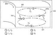
図5Aは、らせん状の形状を有する流体チャネル511を有する、微小流体分離システム510を模式的に図示している。このデザインは、さまざまなサイズの粒子に作用する慣性による揚力と、粘着性の抗力とを有効に利用して、精子のようなミクロ規模の粒子が、分化しながら移動し、そして分離するのを実現するものである。支配的な慣性力と、らせん状のマイクロチャンネルの幾何学的な形状によるディーン回転力とが、より大きな粒子には、マイクロチャネルの内側の壁に近い位置で、1つの均衡位置を占めさせることになる。ディーン力の影響下では、より小さい粒子は、マイクロチャネルの外側の半分に移動して、2つの区別可能な粒子の流れを形成する結果となり、この粒子の流れは、2つの別々の排出口内に回収されることとなり得る。高いアスペクト比を有するチャネルによって生成された大きな揚力により、短い距離の中で、また遅い速度の流れであっても、完全な流離分離又は、濾過が実現され得る。 FIG. 5A schematically illustrates a
らせん状微小流体分離システム510は、内側取り入れ口514a、外側取り入れ口514b、複数のループに配列された流体チャネル511、内側排出口512a、及び外側排出口512bを備え得る。 The spiral
内側取り入れ口514a及び外側取り入れ口514bは、さまざまなサイズの粒子を含有する、多くの粒子で満たされた溶液を受容するように構成され、らせん状微小流体分離システム510の中に溶液が入るのを可能にするようなポート又はその他の接続装置に接続され得る(例えば、シリンジが繋がれるように構成され得る)。代替的な1つの実施形態では、ただ1つの取り入れ口が設けられ得るが、別の1つの実施形態では、3つ以上の取り入れ口が用いられ得る。 The
内側取り入れ口514aと外側取り入れ口514bとは、複数のループ511状に配列されたらせん状流体チャネル511に、流体連結されている。図5Bは、らせん状流体チャネル511の断面図を図示している。流体チャネル511は、2つの第1壁550及び551、並びに2つの第2壁552及び553を有する矩形の断面を有している。第1壁550及び551は、本明細書では、マイクロチャネルの幅を画定するものとして、また、第2壁552及び553は、高さを画定するものとして、言及し得るものである。しかしながら、らせん状微小流体分離システム510の向きについて、なんらの特定の限定を意図してはいない。 The
内側排出口512a及び外側排出口512bは、らせん状マイクロチャネル511の、内側取り入れ口514a及び外側取り入れ口514bとは反対側に位置している。本明細書でより詳細に説明されるように、分離された粒子は、内側排出口512a及び外側排出口512bで、集められ、検出され、計数され、又はその他の方法で分析され得る。 The inner outlet 512a and the outer outlet 512b are located on the opposite side of the
らせん状微小流体分離システム510の設計パラメーターは、ディーン抗力を用いて、より小さい粒子の位置を溶液内で入れ替え、かつ、ディーン抗力と結合された慣性による揚力を用いて、より大きな粒子を溶液内で均衡させて、2つの粒径どうしの間の、完全な又はほぼ完全な分離を実現し得る。これらの力を組み合わせた効果として、粒径に基づく、区別可能な粒子の流れが結果として形成され、これらの流れが、らせん状流体チャネル511内の層流を利用することにより、内側排出口512a及び外側排出口512bで集められる。 The design parameters of the spiral
図5Bは、らせん状流体チャネル511内を流れる粒子に作用する力を更に図示している。らせん状のチャネル内に集まる流れは、慣性による揚力(FL)、すなわち粒子を壁から遠ざけるように押す力と、ディーン抗力(FD)、すなわち横方向の二次的な渦流によって、らせん状チャネルの長さ方向に沿って生成される力との間のバランスを必要とする。このバランスは、所与の粒子タイプに対して、流れのある物理的パラメーターが、ある具体的に特定された範囲にある場合に達成され得るものである。慣性による揚力(FL)とディーン抗力(FD)は、以下の式によりそれぞれ計算可能である:FIG. 5B further illustrates the forces acting on the particles flowing through the

かくして、らせん状流体チャネル511を通って流れる流体は、径方向外側向きの遠心性の加速度を受けることになり、ディーン渦として知られる、2つのそれぞれ反対方向に回転し、それぞれチャネルの上半分と下半分とに存在する渦556a及び556bを形成することとなる。曲線のあるチャネルを流れる粒子(図5Bでは粒子1〜4と標識化してある)は、横断方向のディーン流れにより、抗力を受ける。粒径によるが、この抗力(FD)は、粒子をディーン渦に沿って動かし(すなわち、円運動させ)、それにより、内側又は外側のチャネル壁に向かって移動させる。このディーン抗力FDに加えて、曲線のあるチャネル内の粒子は、水圧による力と慣性による揚力とを受けている。粒子に作用する純揚力(FL)は、せん断力により誘導された慣性による揚力と、壁により誘導された慣性による揚力とを組み合わせたものである。ポアズイユ流れ中、速度プロファイルの放物性は、結果として、流体のせん断力により誘導された慣性による揚力を結果として生み出し、その力は粒子に作用し、かつマイクロチャネルの中心から遠ざかる方向に向かうようになっている。粒子がマイクロチャネルの壁に向かって動くにつれて、非対称的な後流が粒子の周りに誘導されて、壁により誘導され、壁から遠ざかる方向に向かう、慣性による揚力を生み出す。これらの対向する揚力の大きさは、チャネルの断面にわたって変化し、壁により誘導された揚力がチャネル壁(例えば、内側壁552及び外側壁553)の近くでは支配的となり、せん断力により誘導された揚力は、流体チャネル511の中央付近で支配的となっている。したがって、粒子は、反対向きの揚力同士が均しくなり、狭い帯状を形成する位置を占める傾向がある。Thus, the fluid flowing through the
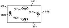
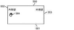
図6A〜6Cは、慣性による移動の原理を模式的に図示している。図6Aは、マイクロチャネル511内を流れる粒子560を図示している。図6Bは、矩形のマイクロチャネル511の場合に、せん断力により誘導された揚力と壁により誘導された揚力とが互いに均衡する均衡位置の数が、低いReの4カ所(位置562a、562b、562c、及び562d)にまで減少することを示している。以下により詳細に説明するように、ディーン抗力(FD)成分を加えることにより、その4カ所の均衡位置の数は更に減少し、図6Cに図示されている内側マイクロチャネル壁(位置564)付近の、たった1つになる。6A to 6C schematically show the principle of movement by inertia. FIG. 6A illustrates
再びここで図5Bを参照すると、らせん状流体チャネル511内に分散した粒子は、流体チャネル511の上半分及び下半分にそれぞれ形成される2つのディーン渦556a及び556bのうちの片方に乗り込むことになる。ディーン抗力と慣性による揚力とは、マイクロチャネル内を1未満のReで流れる中立的に浮揚性の粒子の移動を支配しがちである。流体チャネル上下の壁550及び551付近を流れる粒子(粒子3及び粒子4により図示)は、ディーン抗力FDによる強い横方向の流れを感じ、マイクロチャネル内側壁552及び外側壁553へ向かって押し流される。マイクロチャネル外側壁553付近では、純揚力(FL)がFDの方向に沿って作用し、粒子(粒子2)は、そのサイズに関わらず、ディーン渦556a及び556bに従う動きを続ける。しかしながら、流体チャネル内側壁552付近では、FL及びFDが互いに逆方向に作用し、これらの力の大きさ次第で、粒子(粒子1)は均衡して集束する流れを形成するか、又はディーン渦の中で、再循環し続ける。Referring again to FIG. 5B here, the particles dispersed in the
らせん状流体チャネル内を流れる粒子に作用する力、すなわちディーン抗力及び慣性による揚力、が粒径に依存することは、同じくらいの粒径を有する粒子の、集束する流れを作るために操作することが可能である。らせん状微小流体分離システム510のらせん状の幾何学形状は、より大きな粒子に、単一の均衡位置を、流体チャネルの内側壁552付近で占めさせる。他方、より小さい粒子は、ディーン流によるより大きな粘着性抗力を受け、ディーン渦556a及び556bに沿って再循環を続け、かつ、マイクロチャネル511の外側の半分に移動され得る。このように、らせん状微小流体分離システム510は、より大きな粒子の慣性による移動と、より小さい粒子に対するディーン抗力の影響力とを用いて、異なる粒径の粒子を分離することを実現する。 The dependence of the force acting on the particles flowing through the spiral fluid channel, namely the Dean drag and the lift due to inertia, on the particle size is manipulated to create a focused flow of particles of similar particle size. Is possible. The helical geometry of the helical
完全な粒子の分離を実現するために必要となる、らせん状マイクロチャネル511の長さLfは、以下のように書くことができる:The length L f of the
ここで、図7A〜7Dを参照すると、らせん状微小流体分離システム610の別の1つの実施形態が図示されている。この例示的ならせん状マイクロチャネル粒子セパレータ610は、図7Aに図示されているように、内側取り入れ口614a、外側取り入れ口614b、及び6個の排出口612a〜612fを備える。一部の実施形態では、1つだけの取り入れ口を用い得るということを理解すべきである。あるいは、3つ以上の取り入れ口を用い得る。更に、排出口も図のものよりも多くても少なくてもよい。らせん状微小流体分離システム610は、複数のループ状に配置されたらせん状流体チャネル611を有する。図示された実施形態では、取り入れ口614a及び614bから、複数の排出口612a〜612fまで5つのループが存在している。 Here, with reference to FIGS. 7A-7D, another embodiment of the spiral
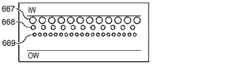
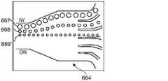
ディーン抗力と慣性による揚力とを組み合わせた結果、流体チャネル内側壁652で、粒子が均衡している。粒子が均衡している位置は、これらの2つの力の比率に依存して決まる。らせん状微小流体分離システム610の幾何学的特性は、2つの力の割合が粒径に依存するということを利用して、分別された、集束する粒子の流れを形成する(図7C及び7Dの、粒径A、B、及びCの粒子の流れにより図示されている)が、その流れは、排出口612a〜612fから取り出され得る。図7Bに図示されているように、粒径A、B、及びC(図8参照)を含む、多くの粒子を含んだ溶液が、内側及び/又は外側取り入れ口614a及び614bから導入される。それぞれのサイズを有する粒子は、流体チャネル611内で混じり合っている。らせん状流体チャネル611内では、粒子粒径による複数の流れに集束し始めている。図7Cに示すように、粒径Aの粒子は、最大の粒子であるが、これらの粒子は、内側壁652に最も近い位置にある第1の流れ667に収束する。粒径Aよりも小さい粒径Bの粒子は、粒径Aの粒子の流れの隣にある第2の流れ668に集束している。粒径Bよりも小さい粒径Cの粒子は、最も外側の第3の流れ669に集束している。 As a result of combining Dean drag and lift due to inertia, the particles are balanced at the fluid channel
複数の排出口612a〜612fの前に、粒子667、668、及び669の流れを、指定された排出口に方向付ける助けとなる幅広部分664が、位置し得る。個別の粒子の流れと流れとの間の分離は、個別の流れを複数の排出口612a〜612fで取り出す前に、らせん状流体チャネル611が、幅広部分664の中に開放されることによって向上する。図7Dを参照すると、複数の排出口612a〜612fは、粒子の集束した流れをそれぞれ受容するように配列されている。第1の粒子の流れ667は、粒径Aの比較的大きな粒子を含むが、らせん状微小流体分離システム610を、排出口612aから出る。第2の粒子の流れ668は、粒径Bの粒子を含むが、らせん状微小流体分離システム610を、排出口612bから出る。粒径Cの最小の粒子は、らせん状微小流体分離システム610を、排出口612cから出る。 In front of the plurality of
図8は、流体チャネル611の断面を示し、FL及びFDの粒子への効果を表す。これらの力の比率(FL/FD)は、所与のサイズ(直径)の粒子がどこで均衡するかを決める(例えば、流れの中又は粒径A、B、又はC)決定要因である。支配的な慣性による揚力は、流体チャネルの内側壁付近にある取り入れ口で無作為的に分配されていた粒子を、流れが下流に進むにつれて、位置合わせしていく。他方、有意なレベルのディーン抗力は、これらの集約された流れを、粒径に応じて、最大の粒子がチャネルの内側壁に最も近くなるように、チャネルの壁から更に遠ざけるように動かす。この結果、異なる粒子の3つの流れが展開されることになるが、これらの流れは、適切な排出口を設計することにより、独立に取り出され得る。Figure 8 shows a cross-section of the
既に説明したとおり、微小流体分離システムの流体チャネルは、微小流体の慣性に基づいて材料を仕分けるためのらせん状の形状を有し得る。微小流体の慣性力は、流れと揚力を均衡させ、らせん状のチャネル内の粒子を集束させ、粒径と形状とに基づいて、異なるチャネル排出口に細胞を向けることが期待されている。このように適切な幾何学的形状と流速とを有するらせん状チャネルを用いることにより、混合液中の精子細胞を他の細胞から分離して濃縮することが可能となる。細胞及び粒子が、らせん状チャネルを通って動くにつれて、逆回転の流れが成立し、チャネル内で粒子を横方向に動かす。細胞及び粒子が、チャネルの側壁に向かって移動するにつれて、揚力が粒子を壁から遠ざけるように押し、粒子を、チャネル内の、流れと揚力が均衡する、均衡位置に動かす。チャネル内の粒子にとって、この均衡位置がどこになるのは粒子のサイズ、形状、流速、及び、らせん状チャネルの幾何学的形状次第で変化する。所与のチャネルの幾何学的形状に対して、異なる粒径と形状の粒子は、チャネル内の異なる位置で集束する。チャネルの幾何学的形状と流速とを最適化することにより、試料内のその他のさまざまな粒子に対して、どこで精子が分離され、集束するかという条件を決定し得る。なお、精子は独特のサイズと形状を有しており、そのことは、こうした方法を精製に利用する好機を、提供するものである。らせん状のチャネルを導入しているので、揚力と集束の場所は、らせんの半径によって大きく影響を受ける。このように、これらのさまざまなパラメーターを操作して、精子細胞を汚染細胞から分離するのに最適なチャネル及び流速を決定することが可能となる。 As described above, the fluid channels of a microfluidic separation system can have a spiral shape for sorting materials based on the inertia of the microfluids. The inertial force of a microfluidic force is expected to balance flow and lift, focus particles within a spiral channel, and direct cells to different channel outlets based on particle size and shape. By using a spiral channel having an appropriate geometry and flow velocity in this way, sperm cells in the mixed solution can be separated from other cells and concentrated. As cells and particles move through the spiral channel, a counter-rotating flow is established, moving the particles laterally within the channel. As cells and particles move toward the side walls of the channel, lift pushes the particles away from the wall, moving the particles into a balanced position within the channel where flow and lift are in equilibrium. For particles in the channel, this equilibrium position depends on the size, shape, flow velocity of the particles and the geometry of the spiral channel. For the geometry of a given channel, particles of different particle sizes and shapes will focus at different locations within the channel. By optimizing the channel geometry and flow velocity, it is possible to determine where sperm are separated and focused for a variety of other particles in the sample. It should be noted that sperm have a unique size and shape, which provides an opportunity to utilize these methods for purification. Due to the introduction of spiral channels, lift and focus location are greatly affected by the radius of the helix. Thus, these various parameters can be manipulated to determine the optimal channels and flow rates for separating sperm cells from contaminated cells.
上に論じてきた理論的原理を用いて、精子を効果的に分離するらせん状流体チャネルを設計することが可能となる。集束に対して、慣性による揚力と、ディーン抗力との間の比率(Rf)は、以下の式で与えられ、 Using the theoretical principles discussed above, it is possible to design spiral fluid channels that effectively separate sperm. The ratio (Rf) between the lift due to inertia and the Dean drag with respect to the focus is given by the following equation.
1つの態様では、流体チャネルは、約25μm〜約100μmの高さを有し得る。別の1つの態様では、流体チャネルは、約50μm〜約400μmの幅を有し得る。更に別の1つの態様では、チャネルのアスペクト比は約0.2〜約0.5であり得る。更にまた別の1つの態様では、らせんの平均半径は約1cm〜約16cmであり得るが、等比級数状になる。更なる態様においては、流体チャネル内の流速は、約0.1mL/分〜約1mL/分であり得るが、より大きなチャネルについては、それよりも速い速度になり得る。排出口の数は、2〜10個であり得るが、ただし、流体チャネルは、任意の好適な数の排出口を有し得る。ある特定の例では、らせん状チャネルは、最初のらせんの半径が0.7cm、最後のらせんの半径が0.899cmであり、チャネルの幅が150μmであり、チャネルの高さが50μmであり、4回らせん状に巻かれており、チャネルどうしの間の隙間は、310μmであってよい。精子を分離するための微小流体分離システムを設計するにあたって直面する課題の1つは、理論上は球状の粒子を想定しているものの実際には不規則な、精子細胞の形状である(精子の頭部の長さは約4.79μmで、幅は約2.82μmである)。ある推測では、精子は、5μm直径の球としてみなし得る。解像度の推測用に、赤血球は、9μmの直径の球として近似し得る(RBCの寸法は:直径が7.5〜8.7μmで、厚みが1.7〜2.2μm)。 In one embodiment, the fluid channel can have a height of about 25 μm to about 100 μm. In another aspect, the fluid channel can have a width of about 50 μm to about 400 μm. In yet another aspect, the channel aspect ratio can be from about 0.2 to about 0.5. In yet another aspect, the average radius of the helix can be from about 1 cm to about 16 cm, but is geometric progression. In a further embodiment, the flow velocity within the fluid channel can be from about 0.1 mL / min to about 1 mL / min, but for larger channels it can be faster. The number of outlets can be 2-10, but the fluid channel can have any suitable number of outlets. In one particular example, the spiral channel has a radius of the first helix of 0.7 cm, a radius of the last helix of 0.899 cm, a width of the channel of 150 μm, and a height of the channel of 50 μm. It is spirally wound four times and the gap between the channels may be 310 μm. One of the challenges faced in designing a microfluidic separation system for sperm separation is the shape of sperm cells, which theoretically assumes spherical particles but is actually irregular (sperm). The length of the head is about 4.79 μm and the width is about 2.82 μm). One speculation is that sperm can be considered as spheres with a diameter of 5 μm. For resolution estimation, red blood cells can be approximated as spheres with a diameter of 9 μm (RBC dimensions: 7.5-8.7 μm in diameter and 1.7-2.2 μm in thickness).
それゆえ、本開示による微小流体分離システムは、細胞のサイズと形状に頼る微小流体の慣性力アプローチに基づき得る。精子は、慣性力微小流体チャネルを用いて同じようなサイズの細胞と比較すると、長い尾部を有するために独特の挙動を示し得るが、そのことは、精子を素早く精製し集める上では役立つものである。このように、動きのない精子を赤血球やその他の汚染細胞から分離するために、らせん状チャネルを用いることが可能である。1つの態様では、分離の技術は、精子のサイズ及び/又は形状特性にフォーカスすることができる。例えば、慣性力の微小流体設計は、精子の尾部が有する「背びれ様」形状の、特定の方向に流すという特性を利用することが可能である。 Therefore, the microfluidic separation system according to the present disclosure can be based on a microfluidic inertial force approach that relies on cell size and shape. Sperm may behave uniquely due to their long tail when compared to cells of similar size using inertial microfluidic channels, which helps in the rapid purification and collection of sperm. is there. Thus, it is possible to use spiral channels to separate immobile sperm from red blood cells and other contaminated cells. In one embodiment, the separation technique can focus on sperm size and / or shape characteristics. For example, a microfluidic design of inertial force can take advantage of the "dorsal fin-like" shape of the sperm tail, which allows it to flow in a particular direction.
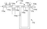
図9は、本開示の1つの例による仕分け/濃縮システム730を模式的に図示している。仕分け/濃縮システム730は、本明細書で開示したような微小流体分離システムからの組織試料材料を受容するための取り入れ口770と、排出口770bとを含み得る。仕分け/濃縮システム730はまた、第1流体導管771及び第2流体導管772をも含み得る。第1流体導管771は、ある所与のサイズの粒子(例えば、組織試料材料のうちの所望のサイズ画分の細胞)がその導管を通ることができないようなサイズ又は形状であり得る。1つの態様では、第1流体導管771は、所望のサイズの粒子を1つ以上受容又は収容可能なサイズのトラップ部776aを有し得るが、第1導管を粒子が通過するのを防ぐように構成されている小サイズ部776b(精子に対しては1.5μm以下の幅を有する)をも有し得る。第1流体導管771の流体抵抗は、所与のサイズの粒子が第1導管に向かって流れて来て、第1導管で捕らわれるようにするように、第2流体導管772の流体抵抗よりも大きくなり得る。加えて、仕分け/濃縮システム730は、複数のアリコート保管チャネル773a、773b(すなわち、固定化チャネル)と、アリコート保管チャネルに、保管(例えば、冷凍保存)のために、アリコートを分離するのを容易にするため、その複数のアリコート保管チャネルと関連付けられた複数のバルブ774a、774bとを含み得る。第1導管771から、そこに捕らわれた粒子を流し、複数のアリコート保管チャネル773a及び773bの中に流すための流体を提供するための還流ライン775が含まれ得る。取り入れ口、排出口、及び還流ライン775は、仕分け/濃縮システム730の動作を容易にするためのバルブ774c〜774eをそれぞれ含み得る。バルブ付き導管777が、流れを制御するために含まれ得る。 FIG. 9 schematically illustrates a sorting /
図10A〜10Cは、動作中の仕分け/濃縮システム730を図示している。図10Aは、組織試料材料がシステムに入ってくるのを可能にするために開放された、取り入れ口770aのバルブ774cと、排出口770bのバルブ774dとを示す。他のバルブは全て閉めてある。そのような場合、組織試料は精子778a〜778dを含み、この精子778a〜778dを濃縮し、仕分けることが望ましい状況である。組織試料材料は、より大きな粒子用のトラップが待っている第1導管771に流入するか、あるいはそのようなトラップを迂回する第2導管772流入するかのいずれかである。しかしながら、第2導管772内の抵抗はより高いため、組織試料内の材料は、好んで第1流体導管771内に流入する。大きな粒子、例えば精子778a〜778cは、第1導管771内で、小サイズ部776b(図10B参照)により捕捉されるが、一方で小さな粒子779は、第1導管771の小サイズ部776bを通過して、排出口770bを介してシステム730から出られるようになっている。大きな粒子(例えば、精子778d)を含む、第1導管771に流入しない任意の粒子は、トラップを迂回することが可能である。2つの流路を提供したことにより、精子778a〜778dがシステム730を通って流れるにつれて、それらがトラップで捕捉されるか又はトラップを迂回するかのいずれかであることが保証される。第2導管772は、所望の流れ抵抗(背圧)を得られるように、その長さ及び/又は断面積を調製することが可能である。一般的なガイドラインとして、設計上のパラメーターは変化し得るが、第2導管は、第1導管よりも0.3〜3倍大きい流れ抵抗を有し得る。1つの態様では、第1導管771のトラップ部776aと、迂回の態様により、所望の数(例えば約1〜約5個)の精子が1つのトラップ内に捕捉されるように構成され得る。所望の数の精子が捕捉されると、図10Bに示すように、取り入れ口バルブ774c及び排出口バルブ774dを閉鎖して、システム730を通る流れをストップできる。図10Cに示すように、還流ライン775のバルブ774e及びアリコート保管チャネル773bのバルブ774bを開放して、精子778a〜778cを、第1チャネル771のトラップ部776aからアリコート保管チャネル773bへと流すことが可能である。あるいは、アリコート保管チャネル773aのバルブ774aを開放し、バルブ774bを閉鎖して、精子をアリコート保管チャネル773aに向かわせるのも可能である。バルブ774a及び774bは、1回精子を流す間に、交互に開放して、捕捉した精子の一部をアリコート保管チャネル773a及び773bに分けることが可能であるが、あるいはバルブ774a及び774bは、精子を1回流すごとに交代して開閉することも可能である。こうして、仕分け/濃縮システム730は、望ましくない粒子を組織試料から除去し、それにより精子を濃縮し、かつ精子をアリコートに仕分けして冷凍保存させることが可能である。なお、2つのアリコート保管チャネルしか図示されていないが、システム730は、任意の好適な数のアリコート保管チャネルと、関連するバルブを含み、捕捉した精子を所定の位置に回すことが可能であるということを、認識すべきである。例えば、精子を準備して、プレートの個々のウェル内に、1度に1つずつ分注することも可能である。1つの態様では、仕分け/濃縮システム730は、単一のトラップしか内蔵していない「チップ」として構成されることも可能である。 10A-10C illustrate the sorting /
仕分け/濃縮システム730は、濃縮システムとして構成することが可能で、その濃縮システムは、アリコート保管チャネルを1つ省いて又は1つだけ用いて、仕分けシステムを兼用させ得る/させないことも可能であるということを認識すべきである。同様に、仕分け/濃縮システム730は、仕分けシステムとして構成することが可能で、その仕分けシステムは、取り入れ口770a、並びにアリコート保管チャネル773a及び773bのバルブ774a〜774cのみを操作することによって、濃縮システムを兼用させ得る/させないことも可能である。 The sorting / concentrating
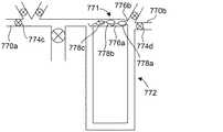
図11は、本開示の別の1つの例による仕分け/濃縮システム830を模式的に図示している。仕分け/濃縮システム830は、トラップと迂回の構成を組み込んだという点で、多くの面で図9の仕分け/濃縮システム730と類似している。しかしながらこの場合、仕分け/濃縮システム830は、直列に配置した複数のトラップと迂回とを含む。この例にはバルブが図示されていないが、仕分け/濃縮システム830は任意の好適な配置でバルブを含むことが可能であり、それにより、比較的大きな粒子、例えば精子を捕捉することを容易にし、既に説明したような方法、例えば連続的なバルブの開閉動作や、逆流を発生させることにより精子をトラップから取り除いて、その大きな粒子をシステム830から回収するのを容易にすることが可能であるということを認識すべきである。 FIG. 11 schematically illustrates a sorting /
本明細書で開示された構成部品は、任意の好適な材料で製造され得るが、例えば、ポリジメチルシロキサン(PDMS)材料、ポリメチルメタクロレート(PMMA)、ポリカーボネート(PC)、及び/又は環状オレフィンコポリマー(COC)が挙げられるが、それらに限られない。 The components disclosed herein can be made of any suitable material, such as a polydimethylsiloxane (PDMS) material, a polymethylmethachrolate (PMMA), a polycarbonate (PC), and / or a cyclic olefin. Copolymers (COCs) include, but are not limited to.
1つの態様では、本明細書で開示される技術は、単一の組織試料処理システムであるが、そのシステムは、試料源が精巣の組織である場合に、体細胞や破片に対して精子を分離して濃縮するために使用可能である。別の1つの態様では、組織試料処理システムはまた、精子試料から冷凍保存用のアリコートを作製することを可能にし、後々に使用することを可能とする。他の能力には、精子を培養して、精子を倍数性に基づいて分離することも含まれる。 In one aspect, the technique disclosed herein is a single tissue sample processing system, which produces sperm against somatic cells and debris when the sample source is testicular tissue. It can be used to separate and concentrate. In another aspect, the tissue sample processing system also allows the aliquots for cryopreservation to be made from sperm samples for later use. Other abilities also include culturing sperm and separating sperm on the basis of ploidy.
本明細書で開示される技術の、更に別の用途は、ヒト及びその他の動物の臨床的生殖補助医療技術(ART)の分野及び生殖研究の分野に存在する。現行の、ART関連精子分離技術は、精子の運動性に依存して分離が行われ、そのために、典型的な分離の方法はしばしばARTでは用いられない一方で、本明細書で開示される方法は、運動している細胞を必要としないため、ARTの分野でも独特のアプローチである。例えば、精巣の組織試料からの少数の細胞を濃縮可能な、本明細書で開示される組織試料処理システムは、男性不妊症の分野における用途に幅広い関わりを用いるものである。組織試料処理システムは、生存している精子を分離することが可能であるだけでなく、他のまばらな細胞型、例えば精原幹細胞やその他の精子前駆体をも分離することが可能である。これは、ヒトの精巣の組織から精原幹細胞を分離する現行の方法が、治療的処置とは両立しない、抗体のような薬剤の使用を伴うということを考慮すると、非常に重要である。重要なことには、組織試料処理システムは、これらの細胞型を、有害な試薬を添加することなく分離し得る。生体外での精原幹細胞分化技術と合わせて用いて、組織試料処理システムは、成熟した精子細胞の培養に用いることができ、現在成熟した精子を作ることができない患者に対して不妊治療を行う場合の、選択肢を提供するものである。 Yet another use of the techniques disclosed herein exists in the field of clinical assisted reproductive technology (ART) and reproductive research in humans and other animals. Current ART-related sperm separation techniques rely on sperm motility for separation, and therefore typical methods of separation are often not used in ART, while the methods disclosed herein. Is a unique approach in the field of ART as it does not require moving cells. For example, the tissue sample processing system disclosed herein, which is capable of concentrating a small number of cells from testis tissue samples, has broad implications for applications in the field of male infertility. The tissue sample processing system is capable of not only separating live sperm, but also other sparse cell types such as spermatogonial stem cells and other sperm precursors. This is very important considering that current methods of isolating spermatogonial stem cells from human testis tissue involve the use of agents such as antibodies that are incompatible with therapeutic treatment. Importantly, the tissue sample processing system can separate these cell types without the addition of harmful reagents. Combined with in vitro sperm stem cell differentiation technology, the tissue sample processing system can be used to culture mature sperm cells and provide fertility treatment for patients who are currently unable to produce mature sperm. It provides a choice of cases.
本技術は、IVFで使用するため個々の精子を選別するためにも用いることが可能である。例えば、組織試料処理システムは、正常な倍数体の(それぞれの染色体のちょうど1つだけを含む)精子細胞を、異常な倍数体の(多すぎる又は少なすぎる1つ以上の染色体を含む)精子細胞から分離するために用いられ得る。IVF用に正常な精子を、質量又は電荷に基づいて分離する能力は、生存する胚を作り出す可能性を高め、一染色体性又は三染色体性の胚ができる可能性を低くする。正常な精子を分離することに加えて、個々の精子の非侵襲的な保存により、それぞれの精子の生殖能力を判定するための非侵襲的な撮像が可能となり、妊娠及び誕生を成功させるために最善の潜在能力を有する精子を発生学者が選択するのを可能にし得る。 The technique can also be used to sort individual sperms for use in IVF. For example, tissue sample processing systems have normal polyploid sperm cells (containing just one of each chromosome) and abnormal polyploid sperm cells (containing one or more chromosomes that are too many or too few). Can be used to separate from. The ability to separate normal sperm for IVF on the basis of mass or charge increases the likelihood of producing viable embryos and reduces the likelihood of producing monochromosomal or trisomy embryos. In addition to separating normal sperm, the non-invasive storage of individual sperm allows non-invasive imaging to determine the fertility of each sperm, for successful pregnancy and birth. It may allow embryologists to select sperm with the best potential.
臨床的な目的に加えて、個々の精巣細胞型を少量の組織から分離して冷凍保存することで、生殖研究の能力を向上させることが可能である。例えば、NOAの患者は、精巣内に、特定の精子形成の中心点を示すが、現在のところ、何が1つの精細管内での精子形成を促進し、他ではそれをしないのかがはっきりとわかっていない。精細管から、特定の細胞下位集団を分離することにより、遺伝子の発現、後生的又はその他の分子分析の実施が可能となり、精子形成を命じる分子的メカニズムが明らかになる可能性を開く。精原幹細胞の分離により、マウスの組織における先端研究を補うためのヒトの組織における多能性転化のプロセスの研究を、研究者が行うことも可能になるであろう。更に、個々の精子細胞を捉えることにより、研究者が、多様な精子集団をバルクで研究するのとは異なる、個別の精子の特性を研究することが可能になり得る。 In addition to clinical purposes, it is possible to improve the ability of reproductive studies by separating individual testis cell types from small amounts of tissue and storing them in a freezer. For example, patients with NOA show a specific central point of spermatogenesis in the testis, but at present it is clear what promotes spermatogenesis in one fine tube and not in others. Not. Separation of specific cell subpopulations from the seminiferous tubules allows gene expression, metazoan or other molecular analysis to be performed, opening up the possibility of revealing the molecular mechanisms that direct spermatogenesis. Separation of sperm stem cells will also allow researchers to study the process of pluripotency conversion in human tissue to supplement advanced studies in mouse tissue. In addition, capturing individual sperm cells may allow researchers to study individual sperm characteristics that differ from studying diverse sperm populations in bulk.
本発明の1つの実施形態によれば、精子細胞を分離する方法が開示される。その方法は、流体チャネルと複数の排出口とを有する微小流体分離システムを得ることを含み得る。その方法は、キャリア流体を流体チャネル内に配置することを更に含み得る。加えて、その方法は、精子試料を流体チャネル内に配置することを含み得るが、流体チャネル内でのキャリア流体及び精子試料の流れは、複数の排出口のうちのそれぞれ1つが、精子試料内の材料の異なるサイズ画分を受容するように、精子試料内の材料をそのサイズに基づいて、複数のサイズ画分に分離するのを容易にし得る。 According to one embodiment of the present invention, a method for separating sperm cells is disclosed. The method may include obtaining a microfluidic separation system with fluid channels and multiple outlets. The method may further include placing the carrier fluid within the fluid channel. In addition, the method may include placing the sperm sample in a fluid channel, but the flow of the carrier fluid and sperm sample in the fluid channel is such that each one of the outlets is in the sperm sample. It may be easy to separate the material in the sperm sample into multiple size fractions based on its size so as to accept different size fractions of the material.
方法の1つの態様では、流体チャネルはらせん状の形状を有する。方法の別の1つの態様では、微小流体分離システムは、キャリア流体を受容するためのキャリア流体取り入れ口及び組織試料を受容するための組織試料取り入れ口を有する取り入れ口ゾーンと、複数の排出口を有する排出口ゾーンと、取り入れ口ゾーンと排出口ゾーンとの間の移送領域とを備えてよく、移送領域は、キャリア流体及び組織試料に対して開かれており、移送領域内の交差流が、組織試料内の材料をサイズに基づいて分離するのを容易にする。方法の更に別の1つの態様では、複数の排出口の少なくとも1つと関連付けられる精子試料内の材料は、運動していない精子細胞を含む。1つの態様では、方法は、仕分けシステムを、複数の排出口の少なくとも1つに関連付けることを更に含んでもよく、複数の排出口のうちのその少なくとも1つと関連付けられる精子試料中の材料は、運動していない精子細胞を含み、かつ、方法は、運動していない精子細胞を複数のアリコートに仕分けることを含む。方法の1つの態様では、仕分けシステムは、複数の排出口のうちの少なくとも1つに関連付けられた組織試料の中の材料を受容するための取り入れ口と、複数のアリコート保管チャネルと、複数のアリコート保管チャネルと関連付けられる、複数のアリコートをアリコート保管チャネルに分離するのを容易にするための複数のバルブとを含んでもよい。 In one aspect of the method, the fluid channel has a spiral shape. In another aspect of the method, the microfluidic separation system has an inlet zone with a carrier fluid inlet for receiving the carrier fluid and a tissue sample intake for receiving the tissue sample, and multiple outlets. The outlet zone may be provided with a transfer area between the intake zone and the discharge port zone, and the transfer area is open to the carrier fluid and the tissue sample, and the cross flow in the transfer area is formed. Facilitates separation of materials in tissue samples based on size. In yet another aspect of the method, the material in the sperm sample associated with at least one of the multiple outlets comprises non-motile sperm cells. In one embodiment, the method may further comprise associating the sorting system with at least one of the plurality of outlets, the material in the sperm sample associated with at least one of the plurality of outlets being motile. The method comprises sorting non-motile sperm cells into a plurality of aliquots. In one aspect of the method, the sorting system comprises an intake for receiving material in a tissue sample associated with at least one of a plurality of outlets, a plurality of aliquot storage channels, and a plurality of aliquots. It may include a plurality of valves associated with the storage channel to facilitate separation of the plurality of aliquots into aliquot storage channels.
本発明の別の1つの実施形態によれば、精子試料から運動していない精子細胞を分離する方法が開示される。その方法は、層流条件下で精子試料を流体チャネルを通して流すことを含み得るが、流体チャネル内の交差流が、内側の流体流れ層内の、運動していない精子細胞を分離するのを容易にする。また、方法は内側の流体流れ層を空間的に分離することを含み得る。 According to another embodiment of the present invention, a method for separating non-motile sperm cells from a sperm sample is disclosed. The method may involve flowing a sperm sample through a fluid channel under laminar flow conditions, but crossflow within the fluid channel facilitates separation of non-motile sperm cells within the inner fluid flow layer. To. The method may also include spatially separating the inner fluid flow layer.
方法の1つの態様では、流体チャネルはらせん状の形状を有してもよい。1つの態様では、方法は、運動していない精子細胞を、流体チャネルの排出口内に受容することを更に含み得る。別の1つの態様では、方法は、運動していない精子細胞を複数のアリコートに仕分けることを更に含み得る。方法の1つの態様では、複数のアリコートのそれぞれは約1〜約20個の運動していない精子細胞を含み得る。方法の別の1つの態様では、複数のアリコートのそれぞれは約1〜約10個の運動していない精子細胞を含み得る。方法の更に別の1つの態様では、複数のアリコートのそれぞれは単一の運動していない精子細胞を含み得る。 In one aspect of the method, the fluid channel may have a spiral shape. In one embodiment, the method may further comprise accepting non-motile sperm cells into the outlet of a fluid channel. In another aspect, the method may further comprise sorting non-motile sperm cells into multiple aliquots. In one aspect of the method, each of the plurality of aliquots may contain from about 1 to about 20 non-motile sperm cells. In another aspect of the method, each of the plurality of aliquots may contain from about 1 to about 10 non-motile sperm cells. In yet another aspect of the method, each of the plurality of aliquots may comprise a single non-motile sperm cell.
本開示の方法においては、特定の順序を要求しないが、一般的に、1つの実施形態では、方法のステップは連続的に実行され得る。 The methods of the present disclosure do not require a particular order, but in general, in one embodiment, the steps of the method can be performed continuously.
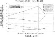
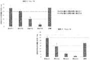
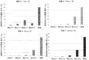
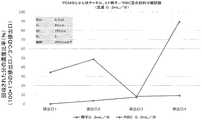
図12A〜22は、本発明の1つの態様による、組織試料処理システムの性能に関する試験データを示す。特に、図12A及び12Bは、高白血球(WBC)精液から精子を分離する能力を示す。図12Aは、らせん状チャネルを用いて分離した後の、異なる排出口のそれぞれでの、細胞濃度測定値を示す。WBCの大半(7.5百万/mL)が、内側壁排出口で集められ、精子の大半(2.55百万/mL)は、外側壁排出口で集められた。図22Bは、83%の精子細胞が外側壁排出口で、94%のWBCが内側壁排出口で集められたことを示す。加えて、少量のRBCも、内側壁排出口で集められた。このように、らせん状チャネルによる精子分離技術は、高濃度のWBCを含む精液試料に対して用いることが可能である。精液中のWBCの濃度が、100万/mLに近い値であったり、それを超える値であったりした場合には、膿精液症(白血球増多症)であると考えられる。ART術を進める前に、精液からWBCを除去すべきである。図21は、4つの排出口それぞれの精子集団の密度を計測するための細胞集計グリッド(例えば、MAKLER細胞計算板)の代表的な部分を示す。 12A-22 show test data on the performance of a tissue sample processing system according to one aspect of the invention. In particular, FIGS. 12A and 12B show the ability to separate sperm from hyperleukocyte (WBC) semen. FIG. 12A shows cell concentration measurements at each of the different outlets after separation using a helical channel. The majority of WBC (7.5 million / mL) was collected at the inner wall outlet and the majority of sperm (2.55 million / mL) was collected at the outer wall outlet. FIG. 22B shows that 83% of sperm cells were collected at the outer wall outlet and 94% of WBC were collected at the inner wall outlet. In addition, a small amount of RBC was also collected at the inner wall outlet. As described above, the sperm separation technique using a spiral channel can be used for a semen sample containing a high concentration of WBC. When the concentration of WBC in semen is close to or exceeds 1 million / mL, it is considered to be purulent semen disease (leukocytosis). WBC should be removed from semen before proceeding with ART. FIG. 21 shows a representative portion of a cell aggregation grid (eg, a MAKLER cell calculator) for measuring the density of sperm populations in each of the four outlets.
前述の詳細な説明は、特定の代表的実施形態を参照して本発明について記載している。しかし、添付の特許請求の範囲に説明されている本発明の範囲を逸脱することなく、種々の修正及び変更を行うことができることが理解されるであろう。詳細な説明及び添付図面は、制限するものではなく、単に例示的なものとしてみなされるものとし、かかる全ての修正又は変更は、たとえあったとしても、本明細書で記載及び説明される本発明の範囲内に収まることが意図されている。 The above-mentioned detailed description describes the present invention with reference to specific representative embodiments. However, it will be appreciated that various modifications and modifications can be made without departing from the scope of the invention as described in the appended claims. The detailed description and accompanying drawings are not intended to be limiting, but are merely to be taken as exemplary, and all such modifications or changes, if any, are described and described herein. It is intended to be within the range of.
Claims (16)
Translated fromJapanese取り入れ口ゾーンに設けられた少なくとも1つの取り入れ口と、前記取り入れ口ゾーンとは反対側の排出口ゾーンに設けられた複数の排出口とを備えた流体チャネルを有し、前記流体チャネルがらせん状形状を備える、微小流体分離システムを入手すること、及び
精子試料を前記流体チャネル内に配置すること、を含み、前記流体チャネル内での前記精子試料の流れは、前記精子試料内の材料を、サイズと形状に基づいて、複数のサイズ形状画分に分離するのを容易にし、前記複数の排出口のそれぞれが、前記精子試料内の前記材料の異なるサイズ形状画分を受容するようになっている、方法。A method of separating sperm cells
It has a fluid channelhaving at least one inlet provided in the intake zone and a plurality of outlets provided in the outlet zone opposite to the intake zone, and thefluid channel is spiral. The flow of the sperm sample in the fluid channel comprises obtaining a microfluidic separation system having ashape and placing the sperm sample in the fluid channel, the material in the sperm sample. It facilitates separation into multiple size shape fractions based on size and shape, and each of the plurality of outletsnow accepts different size shape fractions of the material in the sperm sample. There is a way.
前記微小流体分離システムが更に、前記取り入れ口ゾーンと前記排出口ゾーンとの間にあって前記キャリア流体及び前記組織試料に対して開かれている移送領域を備え、
前記移送領域内の交差流が、前記組織試料内の前記材料を、サイズと形状に基づいて分離するのを容易にする、請求項1に記載の方法。The inlet zonehasa carrier fluid inlet for receiving a carrierfluid,a tissue sample inlet for receiving the tissue sample,
The microfluidic separation system further comprisesa transferarea that is open to thefront Symbol carrier fluid and the tissue sampleI mania and the outlet zone and the inlet zone,
The method of claim 1, wherein the cross-flow in the transfer region facilitates separation of the material in the tissue sample based on size and shape.
前記運動していない精子細胞を、複数のアリコートに仕分けることを更に含む、請求項1に記載の方法。The material in the sperm sample that further comprises associating the sorting system with at least one of the plurality of outlets and associated with said at least one of the plurality of outlets is a non-motile sperm cell. Including and
The method of claim 1, further comprising sorting the non-motile sperm cells into a plurality of aliquots.
前記複数の排出口のうちの前記少なくとも1つに関連付けられる前記組織試料内の前記材料を受容するための取り入れ口と、
複数のアリコート保管チャネルと、
前記複数のアリコート保管チャネルと関連付けられ、前記複数のアリコートを前記アリコート保管チャネルに分離するのを容易にする、複数のバルブと、を備える、請求項4に記載の方法。The sorting system
An intake for receiving the material in the tissue sample associated with at least one of the plurality of outlets.
With multiple aliquot storage channels,
The method ofclaim 4 , comprising a plurality of valves associated with the plurality of aliquot storage channels and facilitating separation of the plurality of aliquots into said aliquot storage channels.
Applications Claiming Priority (3)
| Application Number | Priority Date | Filing Date | Title |
|---|---|---|---|
| US201462066232P | 2014-10-20 | 2014-10-20 | |
| US62/066,232 | 2014-10-20 | ||
| PCT/US2015/056494WO2016064896A1 (en) | 2014-10-20 | 2015-10-20 | Tissue sample processing system and associated methods |
Publications (2)
| Publication Number | Publication Date |
|---|---|
| JP2017531440A JP2017531440A (en) | 2017-10-26 |
| JP6832848B2true JP6832848B2 (en) | 2021-02-24 |
Family
ID=55761430
Family Applications (1)
| Application Number | Title | Priority Date | Filing Date |
|---|---|---|---|
| JP2017521512AExpired - Fee RelatedJP6832848B2 (en) | 2014-10-20 | 2015-10-20 | Tissue sample processing system and related methods |
Country Status (5)
| Country | Link |
|---|---|
| US (1) | US11708556B2 (en) |
| EP (1) | EP3209766A4 (en) |
| JP (1) | JP6832848B2 (en) |
| CA (1) | CA2965138A1 (en) |
| WO (1) | WO2016064896A1 (en) |
Families Citing this family (11)
| Publication number | Priority date | Publication date | Assignee | Title |
|---|---|---|---|---|
| WO2017184721A1 (en) | 2016-04-19 | 2017-10-26 | Regents Of The University Of Minnesota | Cryopreservation compositions and methods involving nanowarming |
| US11517900B2 (en)* | 2017-10-27 | 2022-12-06 | University Of Utah Research Foundation | Microfluidic system for sperm separation and enrichment from various types of sperm samples |
| CN108132208A (en)* | 2017-12-25 | 2018-06-08 | 黄庆 | A kind of spiral shape microchannel and its application method and series and parallel installation method |
| KR20200138352A (en)* | 2018-04-03 | 2020-12-09 | 휴렛-팩커드 디벨롭먼트 컴퍼니, 엘.피. | Microfluidic channels carrying cells of different sizes |
| US11491485B2 (en)* | 2018-04-09 | 2022-11-08 | Cornell University | Rheotaxis-based separation of motile sperm and bacteria using a microfluidic corral system |
| JP7434740B2 (en)* | 2019-07-12 | 2024-02-21 | 株式会社Ihi | Preparation system for test sample liquid and method for preparing test sample liquid |
| WO2021016186A1 (en)* | 2019-07-19 | 2021-01-28 | University Of Utah Research Foundation | Rapid sperm separation based on sperm morphology and motility |
| SE544733C2 (en)* | 2020-07-20 | 2022-10-25 | Javier Cruz | Microfluidic device and method for manipulation of particles in fluids |
| DE102020127787B4 (en)* | 2020-10-22 | 2025-08-14 | Fraunhofer-Gesellschaft zur Förderung der angewandten Forschung eingetragener Verein | Method and cryopreservation device for cryopreserving a plurality of cell aggregates of biological cells |
| CN112401994A (en)* | 2020-11-18 | 2021-02-26 | 南京鼓楼医院 | An integrated device for automatic selection and transfer of embryos based on surgical robots |
| CN112547145B (en)* | 2020-11-19 | 2022-04-12 | 东南大学 | Rare cell rapid screening micro-fluidic device |
Family Cites Families (33)
| Publication number | Priority date | Publication date | Assignee | Title |
|---|---|---|---|---|
| US5514537A (en)* | 1994-11-28 | 1996-05-07 | Board Of Supervisors Of Louisiana State University And Agricultural And Mechanical College | Process and apparatus for sorting spermatozoa |
| US7208265B1 (en)* | 1999-11-24 | 2007-04-24 | Xy, Inc. | Method of cryopreserving selected sperm cells |
| WO2003008102A1 (en) | 2001-07-18 | 2003-01-30 | The Regents Of The University Of Michigan | Microfluidic gravity pump with constant flow rate |
| AU2003216175A1 (en) | 2002-02-04 | 2003-09-02 | Colorado School Of Mines | Laminar flow-based separations of colloidal and cellular particles |
| JP4557551B2 (en)* | 2002-02-27 | 2010-10-06 | ミシガン大学リージェンツ | Motile sperm sorting |
| MXPA05001654A (en) | 2002-08-15 | 2005-10-18 | Xy Inc | High resolution flow cytometer. |
| MX350776B (en)* | 2003-03-28 | 2017-09-15 | Inguran Llc * | Apparatus, methods and processes for sorting particles and for providing sex-sorted animal sperm. |
| WO2004108011A1 (en) | 2003-06-06 | 2004-12-16 | The Regents Of The University Of Michigan | Integrated microfluidic sperm isolation and insemination device |
| EP1663460B1 (en) | 2003-09-04 | 2015-07-08 | Premium Genetics (UK) Limited | Multiple laminar flow-based particle and cellular separation with laser steering |
| NZ550196A (en)* | 2004-03-29 | 2010-11-26 | Inguran Llc | Method for sorting sperm cells into X or Y chromosome-bearing enriched populations comprising a composition which inhibits motility and a DNA-selective dye |
| US20060118167A1 (en) | 2004-12-03 | 2006-06-08 | Xy, Inc. | Pressure regulated continuously variable volume container for fluid delivery |
| NZ562203A (en) | 2005-04-07 | 2010-09-30 | Xy Llc | Flow path conditioner system utilising an antimicrobial aqueous solvent composition |
| US20090018895A1 (en)* | 2007-03-12 | 2009-01-15 | Lee S. Weinblatt | Technique for correlating purchasing behavior of a consumer to advertisements |
| CN101765762B (en) | 2007-04-16 | 2013-08-14 | 通用医疗公司以马萨诸塞州通用医疗公司名义经营 | Systems and methods for aggregating particles in microchannels |
| FR2931141B1 (en) | 2008-05-13 | 2011-07-01 | Commissariat Energie Atomique | MICROFLUIDIC SYSTEM AND METHOD FOR THE SORTING OF AMAS FROM CELLS AND PREFERENCE FOR CONTINUOUS ENCAPSULATION THROUGH THEIR SORTING |
| WO2009151624A1 (en) | 2008-06-13 | 2009-12-17 | Xy, Inc. | Lubricious microfluidic flow path system |
| US9157550B2 (en)* | 2009-01-05 | 2015-10-13 | The Board Of Trustees Of The University Of Illinois | Microfluidic systems and methods |
| JP2010281701A (en)* | 2009-06-05 | 2010-12-16 | Tohoku Univ | Microparticle continuous sorting / measurement device and microfluidic chip |
| US8535536B1 (en) | 2009-07-04 | 2013-09-17 | University Of Utah Research Foundation | Cross-flow split-thin-flow cell |
| WO2011005781A1 (en) | 2009-07-06 | 2011-01-13 | Sony Corporation | Microfluidic device |
| US8208138B2 (en)* | 2009-09-24 | 2012-06-26 | University Of Cincinnati | Spiral microchannel particle separators, straight microchannel particle separators, and continuous particle separator and detector systems |
| JP5624629B2 (en) | 2009-12-23 | 2014-11-12 | サイトベラ,インコーポレイテッド | System and method for filtering particles |
| EP2542661B1 (en) | 2010-03-04 | 2020-04-22 | National University of Singapore | Detection of circulating tumor cells in a microfluidic sorter |
| CN102242055B (en) | 2011-06-03 | 2013-08-14 | 博奥生物有限公司 | Method for evaluating sperm activity and screening sperms and special microfluidic chip device for same |
| TWI613294B (en) | 2011-09-14 | 2018-02-01 | 臺北醫學大學 | Microfluidic chips for acquiring sperms with high motility, productions and applications thereof |
| US9149806B2 (en) | 2012-01-10 | 2015-10-06 | Biopico Systems Inc | Microfluidic devices and methods for cell sorting, cell culture and cells based diagnostics and therapeutics |
| US9987632B2 (en) | 2012-02-03 | 2018-06-05 | University Of Cincinnati | Microfluidic methods for passive separation of cells and particles |
| US9494568B2 (en) | 2012-02-03 | 2016-11-15 | Neobios Pte Ltd | Passive microfluidic device and a method of forming the same |
| WO2013128561A1 (en)* | 2012-02-28 | 2013-09-06 | 株式会社メニコン | Cell manipulation implement |
| WO2013129947A1 (en)* | 2012-02-29 | 2013-09-06 | Auckland Uniservices Limited | Method and apparatus for the isolation of motile sperm |
| CN104797340A (en)* | 2012-09-21 | 2015-07-22 | 麻省理工学院 | Micro-fluidic device and uses thereof |
| WO2014085801A1 (en) | 2012-11-30 | 2014-06-05 | The Broad Institute, Inc. | Cryo-treatment in a microfluidic device |
| US10371622B2 (en) | 2013-03-14 | 2019-08-06 | Inguran, Llc | Device for high throughput sperm sorting |
- 2015
- 2015-10-20JPJP2017521512Apatent/JP6832848B2/ennot_activeExpired - Fee Related
- 2015-10-20USUS15/520,795patent/US11708556B2/enactiveActive
- 2015-10-20WOPCT/US2015/056494patent/WO2016064896A1/enactiveApplication Filing
- 2015-10-20EPEP15852164.1Apatent/EP3209766A4/ennot_activeWithdrawn
- 2015-10-20CACA2965138Apatent/CA2965138A1/ennot_activeAbandoned
Also Published As
| Publication number | Publication date |
|---|---|
| CA2965138A1 (en) | 2016-04-28 |
| US11708556B2 (en) | 2023-07-25 |
| EP3209766A4 (en) | 2018-08-15 |
| JP2017531440A (en) | 2017-10-26 |
| US20170306288A1 (en) | 2017-10-26 |
| WO2016064896A1 (en) | 2016-04-28 |
| EP3209766A1 (en) | 2017-08-30 |
Similar Documents
| Publication | Publication Date | Title |
|---|---|---|
| JP6832848B2 (en) | Tissue sample processing system and related methods | |
| US11446664B2 (en) | Combined sorting and concentrating particles in a microfluidic device | |
| CN107702973B (en) | Whole blood plasma separation system and method | |
| CN105745021B (en) | Microfluidic methods and systems for separating particle clusters | |
| CN109580323B (en) | Spiral micro-channel and use method thereof and serial and parallel connection mounting structure | |
| CN104111190B (en) | A kind of Double helix micro-fluidic chip | |
| CN115369011A (en) | Systems and methods for sperm sorting | |
| WO2021013066A1 (en) | Microfluidic chip suitable for capturing circulating tumour cells | |
| WO2019117800A1 (en) | Microfluidic device and method for cell separation of a blood sample | |
| CN207366327U (en) | A kind of whole blood blood plasma piece-rate system | |
| CA2782176A1 (en) | Methods and apparatus for segregation of particles, including segregation and proliferation of fetal and stem cells | |
| US20230033651A1 (en) | Microfluidic systems and methods for low-shear isolation of rare cells from large sample volumes | |
| WO2020097048A1 (en) | Systems and methods for sorting particles using hydrodynamic sizing | |
| JP5877512B2 (en) | Sperm collection device with good mobility | |
| AU2022268371A1 (en) | Microfluidic device | |
| Jiang | Inertial microfluidics for circulating tumor cell separation and detection | |
| Zhang et al. | On-chip sample preparations for point-of-care cellular analysis of blood | |
| HK1242781B (en) | Combined sorting and concentrating particles in a microfluidic device | |
| HK1243765B (en) | Combined sorting and concentrating particles in a microfluidic device | |
| HK1242781A1 (en) | Combined sorting and concentrating particles in a microfluidic device |
Legal Events
| Date | Code | Title | Description |
|---|---|---|---|
| A621 | Written request for application examination | Free format text:JAPANESE INTERMEDIATE CODE: A621 Effective date:20181015 | |
| A977 | Report on retrieval | Free format text:JAPANESE INTERMEDIATE CODE: A971007 Effective date:20190724 | |
| A131 | Notification of reasons for refusal | Free format text:JAPANESE INTERMEDIATE CODE: A131 Effective date:20190806 | |
| A601 | Written request for extension of time | Free format text:JAPANESE INTERMEDIATE CODE: A601 Effective date:20191029 | |
| A521 | Request for written amendment filed | Free format text:JAPANESE INTERMEDIATE CODE: A523 Effective date:20191224 | |
| A131 | Notification of reasons for refusal | Free format text:JAPANESE INTERMEDIATE CODE: A131 Effective date:20200421 | |
| A521 | Request for written amendment filed | Free format text:JAPANESE INTERMEDIATE CODE: A523 Effective date:20200716 | |
| TRDD | Decision of grant or rejection written | ||
| A01 | Written decision to grant a patent or to grant a registration (utility model) | Free format text:JAPANESE INTERMEDIATE CODE: A01 Effective date:20210105 | |
| A61 | First payment of annual fees (during grant procedure) | Free format text:JAPANESE INTERMEDIATE CODE: A61 Effective date:20210202 | |
| R150 | Certificate of patent or registration of utility model | Ref document number:6832848 Country of ref document:JP Free format text:JAPANESE INTERMEDIATE CODE: R150 | |
| LAPS | Cancellation because of no payment of annual fees |