JP6832331B2 - Vehicle control device - Google Patents
Vehicle control deviceDownload PDFInfo
- Publication number
- JP6832331B2 JP6832331B2JP2018240419AJP2018240419AJP6832331B2JP 6832331 B2JP6832331 B2JP 6832331B2JP 2018240419 AJP2018240419 AJP 2018240419AJP 2018240419 AJP2018240419 AJP 2018240419AJP 6832331 B2JP6832331 B2JP 6832331B2
- Authority
- JP
- Japan
- Prior art keywords
- deceleration force
- power plant
- additional
- additional deceleration
- vehicle
- Prior art date
- Legal status (The legal status is an assumption and is not a legal conclusion. Google has not performed a legal analysis and makes no representation as to the accuracy of the status listed.)
- Active
Links
Images


Classifications
- B—PERFORMING OPERATIONS; TRANSPORTING
- B60—VEHICLES IN GENERAL
- B60W—CONJOINT CONTROL OF VEHICLE SUB-UNITS OF DIFFERENT TYPE OR DIFFERENT FUNCTION; CONTROL SYSTEMS SPECIALLY ADAPTED FOR HYBRID VEHICLES; ROAD VEHICLE DRIVE CONTROL SYSTEMS FOR PURPOSES NOT RELATED TO THE CONTROL OF A PARTICULAR SUB-UNIT
- B60W10/00—Conjoint control of vehicle sub-units of different type or different function
- B60W10/04—Conjoint control of vehicle sub-units of different type or different function including control of propulsion units
- B—PERFORMING OPERATIONS; TRANSPORTING
- B60—VEHICLES IN GENERAL
- B60W—CONJOINT CONTROL OF VEHICLE SUB-UNITS OF DIFFERENT TYPE OR DIFFERENT FUNCTION; CONTROL SYSTEMS SPECIALLY ADAPTED FOR HYBRID VEHICLES; ROAD VEHICLE DRIVE CONTROL SYSTEMS FOR PURPOSES NOT RELATED TO THE CONTROL OF A PARTICULAR SUB-UNIT
- B60W10/00—Conjoint control of vehicle sub-units of different type or different function
- B60W10/18—Conjoint control of vehicle sub-units of different type or different function including control of braking systems
- B60W10/184—Conjoint control of vehicle sub-units of different type or different function including control of braking systems with wheel brakes
- B60W10/188—Conjoint control of vehicle sub-units of different type or different function including control of braking systems with wheel brakes hydraulic brakes
- B—PERFORMING OPERATIONS; TRANSPORTING
- B60—VEHICLES IN GENERAL
- B60W—CONJOINT CONTROL OF VEHICLE SUB-UNITS OF DIFFERENT TYPE OR DIFFERENT FUNCTION; CONTROL SYSTEMS SPECIALLY ADAPTED FOR HYBRID VEHICLES; ROAD VEHICLE DRIVE CONTROL SYSTEMS FOR PURPOSES NOT RELATED TO THE CONTROL OF A PARTICULAR SUB-UNIT
- B60W30/00—Purposes of road vehicle drive control systems not related to the control of a particular sub-unit, e.g. of systems using conjoint control of vehicle sub-units
- B60W30/02—Control of vehicle driving stability
- B60W30/045—Improving turning performance
- B—PERFORMING OPERATIONS; TRANSPORTING
- B60—VEHICLES IN GENERAL
- B60W—CONJOINT CONTROL OF VEHICLE SUB-UNITS OF DIFFERENT TYPE OR DIFFERENT FUNCTION; CONTROL SYSTEMS SPECIALLY ADAPTED FOR HYBRID VEHICLES; ROAD VEHICLE DRIVE CONTROL SYSTEMS FOR PURPOSES NOT RELATED TO THE CONTROL OF A PARTICULAR SUB-UNIT
- B60W30/00—Purposes of road vehicle drive control systems not related to the control of a particular sub-unit, e.g. of systems using conjoint control of vehicle sub-units
- B60W30/18—Propelling the vehicle
- B60W30/18009—Propelling the vehicle related to particular drive situations
- B60W30/18109—Braking
- B60W30/18136—Engine braking
- B—PERFORMING OPERATIONS; TRANSPORTING
- B60—VEHICLES IN GENERAL
- B60W—CONJOINT CONTROL OF VEHICLE SUB-UNITS OF DIFFERENT TYPE OR DIFFERENT FUNCTION; CONTROL SYSTEMS SPECIALLY ADAPTED FOR HYBRID VEHICLES; ROAD VEHICLE DRIVE CONTROL SYSTEMS FOR PURPOSES NOT RELATED TO THE CONTROL OF A PARTICULAR SUB-UNIT
- B60W40/00—Estimation or calculation of non-directly measurable driving parameters for road vehicle drive control systems not related to the control of a particular sub unit, e.g. by using mathematical models
- B60W40/10—Estimation or calculation of non-directly measurable driving parameters for road vehicle drive control systems not related to the control of a particular sub unit, e.g. by using mathematical models related to vehicle motion
- B—PERFORMING OPERATIONS; TRANSPORTING
- B60—VEHICLES IN GENERAL
- B60W—CONJOINT CONTROL OF VEHICLE SUB-UNITS OF DIFFERENT TYPE OR DIFFERENT FUNCTION; CONTROL SYSTEMS SPECIALLY ADAPTED FOR HYBRID VEHICLES; ROAD VEHICLE DRIVE CONTROL SYSTEMS FOR PURPOSES NOT RELATED TO THE CONTROL OF A PARTICULAR SUB-UNIT
- B60W10/00—Conjoint control of vehicle sub-units of different type or different function
- B60W10/04—Conjoint control of vehicle sub-units of different type or different function including control of propulsion units
- B60W10/06—Conjoint control of vehicle sub-units of different type or different function including control of propulsion units including control of combustion engines
- B—PERFORMING OPERATIONS; TRANSPORTING
- B60—VEHICLES IN GENERAL
- B60W—CONJOINT CONTROL OF VEHICLE SUB-UNITS OF DIFFERENT TYPE OR DIFFERENT FUNCTION; CONTROL SYSTEMS SPECIALLY ADAPTED FOR HYBRID VEHICLES; ROAD VEHICLE DRIVE CONTROL SYSTEMS FOR PURPOSES NOT RELATED TO THE CONTROL OF A PARTICULAR SUB-UNIT
- B60W2520/00—Input parameters relating to overall vehicle dynamics
- B60W2520/16—Pitch
- B—PERFORMING OPERATIONS; TRANSPORTING
- B60—VEHICLES IN GENERAL
- B60W—CONJOINT CONTROL OF VEHICLE SUB-UNITS OF DIFFERENT TYPE OR DIFFERENT FUNCTION; CONTROL SYSTEMS SPECIALLY ADAPTED FOR HYBRID VEHICLES; ROAD VEHICLE DRIVE CONTROL SYSTEMS FOR PURPOSES NOT RELATED TO THE CONTROL OF A PARTICULAR SUB-UNIT
- B60W2540/00—Input parameters relating to occupants
- B60W2540/18—Steering angle
- B—PERFORMING OPERATIONS; TRANSPORTING
- B60—VEHICLES IN GENERAL
- B60W—CONJOINT CONTROL OF VEHICLE SUB-UNITS OF DIFFERENT TYPE OR DIFFERENT FUNCTION; CONTROL SYSTEMS SPECIALLY ADAPTED FOR HYBRID VEHICLES; ROAD VEHICLE DRIVE CONTROL SYSTEMS FOR PURPOSES NOT RELATED TO THE CONTROL OF A PARTICULAR SUB-UNIT
- B60W2710/00—Output or target parameters relating to a particular sub-units
- B60W2710/06—Combustion engines, Gas turbines
- B—PERFORMING OPERATIONS; TRANSPORTING
- B60—VEHICLES IN GENERAL
- B60W—CONJOINT CONTROL OF VEHICLE SUB-UNITS OF DIFFERENT TYPE OR DIFFERENT FUNCTION; CONTROL SYSTEMS SPECIALLY ADAPTED FOR HYBRID VEHICLES; ROAD VEHICLE DRIVE CONTROL SYSTEMS FOR PURPOSES NOT RELATED TO THE CONTROL OF A PARTICULAR SUB-UNIT
- B60W2710/00—Output or target parameters relating to a particular sub-units
- B60W2710/18—Braking system
- B60W2710/182—Brake pressure, e.g. of fluid or between pad and disc
- B—PERFORMING OPERATIONS; TRANSPORTING
- B60—VEHICLES IN GENERAL
- B60W—CONJOINT CONTROL OF VEHICLE SUB-UNITS OF DIFFERENT TYPE OR DIFFERENT FUNCTION; CONTROL SYSTEMS SPECIALLY ADAPTED FOR HYBRID VEHICLES; ROAD VEHICLE DRIVE CONTROL SYSTEMS FOR PURPOSES NOT RELATED TO THE CONTROL OF A PARTICULAR SUB-UNIT
- B60W2720/00—Output or target parameters relating to overall vehicle dynamics
- B60W2720/12—Lateral speed
- B60W2720/125—Lateral acceleration
Landscapes
- Engineering & Computer Science (AREA)
- Transportation (AREA)
- Mechanical Engineering (AREA)
- Chemical & Material Sciences (AREA)
- Combustion & Propulsion (AREA)
- Automation & Control Theory (AREA)
- Physics & Mathematics (AREA)
- Mathematical Physics (AREA)
- Regulating Braking Force (AREA)
- Control Of Driving Devices And Active Controlling Of Vehicle (AREA)
- Electrical Control Of Ignition Timing (AREA)
- Steering Control In Accordance With Driving Conditions (AREA)
Description
Translated fromJapanese本発明は、車両制御装置に関する。 The present invention relates to a vehicle control device.
自動車の旋回性を向上させる車両制御装置として、旋回開始時に運転者のブレーキ操作とは無関係に減速力を生じさせることによって、車両の荷重を前輪側に移動させ、車両の旋回性を高めるものが公知である(例えば、特許文献1)。車両の荷重が前輪側に移動することによって、前輪と路面との摩擦力が増加し、前輪に生じる横力が増加して車両の旋回性が向上する。 As a vehicle control device that improves the turning performance of a vehicle, a vehicle control device that moves the load of the vehicle to the front wheel side by generating a deceleration force at the start of turning regardless of the driver's braking operation to improve the turning performance of the vehicle. It is known (for example, Patent Document 1). When the load of the vehicle moves to the front wheels side, the frictional force between the front wheels and the road surface increases, the lateral force generated on the front wheels increases, and the turning performance of the vehicle improves.
特許文献1に係る車両制御装置では、ディスクブレーキ等の車両に設けられたブレーキによって旋回性を向上させるための減速力を発生させている。しかし、旋回性を向上させるための減速力を発生させるためにブレーキを使用すると、ブレーキの作動頻度が増えるため、摩擦材が摩耗すると共に、ブレーキの温度が上昇する虞がある。そのため、パワープラントによって旋回性を向上させるための減速力を発生させることが検討されている。しかし、パワープラントは車両の状態に応じて減速力を発生させることが困難な場合がある。 In the vehicle control device according to
本発明は、以上の背景を鑑み、減速力を与えることによって車両の旋回性を高める車両制御装置において、減速力を発生させる装置を適切に選択することを課題とする。 In view of the above background, it is an object of the present invention to appropriately select a device that generates a deceleration force in a vehicle control device that enhances the turning performance of a vehicle by applying a deceleration force.
上記課題を解決するために本発明の一態様は、車両(1)のブレーキ(20)及びパワープラント(6)を制御する車両制御装置(30)であって、前輪舵角を含む車両状態情報を取得する車両状態検出装置(34)と、前記車両状態情報に基づいて前記車両に加えるべき付加ピッチモーメントを演算する付加ピッチモーメント演算部(36)と、前記付加ピッチモーメントに基づいて前記車両に発生させるべき、減速側を負の値とした付加減速力を演算する減速力演算部(37)と、前記付加減速力と、前記ブレーキ及び前記パワープラントの状態情報とに基づいて、前記ブレーキが発生させるべきブレーキ付加減速力と前記パワープラントが発生させるパワープラント付加減速力とを演算する減速力分配部(38)とを有することを特徴とする。ここで、減速力は、加速側を正、減速側を負の値とする。 In order to solve the above problems, one aspect of the present invention is a vehicle control device (30) that controls a brake (20) and a power plant (6) of the vehicle (1), and vehicle state information including a front wheel steering angle. The vehicle state detection device (34) for acquiring the above, the additional pitch moment calculation unit (36) for calculating the additional pitch moment to be added to the vehicle based on the vehicle state information, and the vehicle based on the additional pitch moment. Based on the deceleration force calculation unit (37) that calculates the additional deceleration force with the deceleration side as a negative value to be generated, the additional deceleration force, and the state information of the brake and the power plant, the brake It is characterized by having a deceleration force distribution unit (38) that calculates a brake additional deceleration force to be generated and a power plant additional deceleration force generated by the power plant. Here, the deceleration force has a positive value on the acceleration side and a negative value on the deceleration side.
この態様によれば、ブレーキだけでなくパワープラントも利用して旋回性を向上させるための減速力を発生させることができるため、ブレーキの使用を抑制することができる。また、パワープラントが減速力を発生させることが難しい状態では、ブレーキを使用して減速力を発生させることができる。車両制御装置は、減速力を発生させる装置を適切に選択することができる。 According to this aspect, not only the brake but also the power plant can be used to generate a deceleration force for improving the turning performance, so that the use of the brake can be suppressed. Further, when it is difficult for the power plant to generate the deceleration force, the brake can be used to generate the deceleration force. The vehicle control device can appropriately select a device that generates a deceleration force.
上記の態様において、前記減速力分配部は、予め設定されたパワープラント分配不可条件が成立したときに、前記付加減速力に基づいて前記ブレーキ付加減速力を演算し、かつ前記パワープラント付加減速力に0を設定するとよい。 In the above aspect, the deceleration force distribution unit calculates the brake additional deceleration force based on the additional deceleration force when the preset power plant distribution disabling condition is satisfied, and the power plant additional deceleration force. Should be set to 0.
この態様によれば、パワープラントによって減速力を発生させることが難しい状態ではブレーキによって減速力を発生させることができる。 According to this aspect, the deceleration force can be generated by the brake in a state where it is difficult to generate the deceleration force by the power plant.
上記の態様において、前記減速力分配部は、前記ブレーキ付加減速力に0より小さい値を設定し、前記パワープラント付加減速力に0を設定した場合において、前記パワープラント分配不可条件が成立から不成立に変化しても、前記付加減速力が0になるまで前記パワープラント付加減速力を0に維持するとよい。 In the above aspect, when the deceleration force distribution unit sets the brake additional deceleration force to a value smaller than 0 and the power plant additional deceleration force is set to 0, the power plant distribution disabling condition is not satisfied. Even if it changes to, the power plant additional deceleration force may be maintained at 0 until the additional deceleration force becomes 0.
この態様によれば、減速力を発生させる装置をブレーキからパワープラントに切り替えることに起因する、減速度の変動を抑制することができる。ブレーキとパワープラントとは、応答性に差があるため、減速力を発生させる装置をブレーキからパワープラントに単純に切り替えると、減速度が変動し、乗員が違和感を覚える。本態様では、ブレーキが減速力を発生させている状態では、パワープラント分配不可条件の成立、不成立に関わらず、減速力を発生する装置を切り替えないため、減速度の変動を抑制することができる。 According to this aspect, the fluctuation of deceleration caused by switching the device for generating the deceleration force from the brake to the power plant can be suppressed. Since there is a difference in responsiveness between the brake and the power plant, if the device that generates the deceleration force is simply switched from the brake to the power plant, the deceleration will fluctuate and the occupant will feel uncomfortable. In this embodiment, in the state where the brake is generating the deceleration force, the device that generates the deceleration force is not switched regardless of whether the power plant distribution disabling condition is satisfied or not, so that the fluctuation of the deceleration can be suppressed. ..
上記の態様において、前記減速力分配部は、前記パワープラント分配不可条件が不成立であり、かつ前記付加減速力が所定の判定値以上のときに、前記パワープラント付加減速力に前記付加減速力を設定し、かつ前記ブレーキ付加減速力に0を設定するとよい。 In the above aspect, the deceleration force distribution unit applies the additional deceleration force to the power plant additional deceleration force when the power plant distributability condition is not satisfied and the additional deceleration force is equal to or more than a predetermined determination value. It is preferable to set and set the brake additional deceleration force to 0.
この態様によれば、パワープラントによって減速力を発生させることができる。 According to this aspect, a deceleration force can be generated by the power plant.
上記の態様において、前記減速力分配部は、前記パワープラント付加減速力に0より小さい値を設定し、前記ブレーキ付加減速力に0を設定した場合において、前記パワープラント分配不可条件が不成立から成立に変化しても、前記付加減速力が0になるまで前記ブレーキ付加減速力を0に維持するとよい。 In the above aspect, when the deceleration force distribution unit sets the power plant additional deceleration force to a value smaller than 0 and the brake additional deceleration force is set to 0, the power plant distribution disabling condition is not satisfied. Even if it changes to, the brake additional deceleration force may be maintained at 0 until the additional deceleration force becomes 0.
この態様によれば、減速力を発生させる装置をブレーキからパワープラントに切り替えることに起因する、減速度の変動を抑制することができる。 According to this aspect, the fluctuation of deceleration caused by switching the device for generating the deceleration force from the brake to the power plant can be suppressed.
上記の態様において、前記減速力分配部は、前記パワープラント分配不可条件が不成立であり、かつ前記付加減速力が前記判定値より小さいときに、前記パワープラント付加減速力に前記判定値を設定すると共に、かつ前記ブレーキ付加減速力に前記付加減速力から前記判定値を引いた値を設定するとよい。 In the above embodiment, the deceleration force distribution unit sets the determination value for the power plant additional deceleration force when the power plant distributability condition is not satisfied and the additional deceleration force is smaller than the determination value. At the same time, it is preferable to set the brake additional deceleration force to a value obtained by subtracting the determination value from the additional deceleration force.
この態様によれば、パワープラントによって可能な限り減速力を発生させ、減速力の不足分をブレーキによって発生させることができる。 According to this aspect, the deceleration force can be generated as much as possible by the power plant, and the shortage of the deceleration force can be generated by the brake.
上記の態様において、前記パワープラントは、前記付加減速力を実現するために、点火時期をリタードさせるとよい。 In the above aspect, the power plant may retard the ignition timing in order to realize the additional deceleration force.
この態様によれば、簡単な手法でパワープラントが付加減速力を発生させることができる。 According to this aspect, the power plant can generate an additional deceleration force by a simple method.
以上の構成によれば、減速力を与えることによって車両の旋回性を高める車両制御装置において、減速力を発生させる装置を適切に選択することができる。 According to the above configuration, in the vehicle control device that enhances the turning performance of the vehicle by applying the deceleration force, the device that generates the deceleration force can be appropriately selected.
以下、図面を参照して、本発明に係る車両制御装置の実施形態について説明する。 Hereinafter, embodiments of the vehicle control device according to the present invention will be described with reference to the drawings.
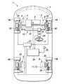
図1に示すように、実施形態に係る4輪自動車である車両1は、車両1の骨格をなす車体2と、サスペンション装置3を介して車体2に支持された前輪4A及び後輪4B(車輪)とを有する。 As shown in FIG. 1, the
本実施形態に係る車両1は、前輪4Aを駆動するパワープラント6を有する。パワープラント6は、ガソリンエンジンやディーゼルエンジン等の内燃機関及び電動モータの少なくとも一方であってよい。本実施形態に係る車両1は、パワープラント6がガソリンエンジンであり、パワープラント6の駆動力及び減速力(制動力)が前輪4Aに伝達される前輪駆動車である。パワープラント6は、例えば点火時期をリタードする(遅らせる)リタード制御によって、発生トルクを低減させ、前輪4Aに減速力を与えることができる。 The
各サスペンション装置3は、車体2に回動可能に支持されたサスペンションアーム7と、サスペンションアーム7に支持され、前輪4A及び後輪4Bを回転可能に支持するナックル8と、車体2とサスペンションアーム7との間に設けられたばね11及びショックアブソーバ12とを有する。 Each
車両1の操舵装置15は、自身の軸線を中心として回動可能に支持されたステアリングシャフト16と、ステアリングシャフト16の一端に設けられたステアリングホイール17と、ステアリングシャフト16の他端に設けられたピニオンに噛み合うと共に、左右に延びて左右両端においてタイロッドを介して前輪4Aに対応した左右のナックル8に連結されたラック軸18とを有する。ステアリングシャフト16に連結されたステアリングホイール17が回転すると、ラック軸18が左右に移動して前輪4Aに対応したナックル8が回動し、左右の前輪4Aが転舵する。また、ステアリングシャフト16には、運転者による操舵に応じてアシストトルクを付与する電動モータが設けられている。 The
各前輪4A及び後輪4Bには、それぞれブレーキ20が設けられている。ブレーキ20は、例えばディスクブレーキであり、油圧供給装置21から供給される油圧によって制御され、対応する前輪4A及び後輪4Bに制動力を与える。油圧供給装置21は各ブレーキ20に供給する油圧を独立して制御することができ、各ブレーキ20が対応する前輪4A及び後輪4Bに与える制動力は互いに独立して変更可能である。 A
車両1には、制御装置30(車両制御装置)が設けられている。制御装置30は、マイクロコンピュータやROM、RAM、周辺回路、入出力インタフェース、各種ドライバ等から構成された電子制御回路(ECU)である。制御装置30は、複数の制御を実行し、一つの制御として、ブレーキペダルの操作量に基づいて各ブレーキ20が発生すべき目標制動力を演算し、目標制動力に応じて油圧供給装置21を制御する。また、制御装置30は、他の一つの制御として、アクセルペダルの操作量に基づいてパワープラント6を制御する。 The
本実施形態では、制御装置30は、運転者のブレーキペダル操作に関わらず、車両の運動状態を表す車両状態量に基づいて、車両1に付加すべき付加ピッチモーメントMYadd(k)を演算し、演算した付加ピッチモーメントMYadd(k)を発生させるべく、ブレーキ20及びパワープラント6の少なくとも一方を制御する。車両状態量には、前輪4Aの舵角である前輪舵角や、車両1の速度である車速、車両1に実際に生じている実ヨーレート等が含まれる。In the present embodiment, the control device 30 calculates an additional pitch moment M Yadd (k) to be added to the
車体2には、車両状態検出手段としての車速センサ33、前輪舵角センサ34、ヨーレートセンサ35が設けられている。車速センサ33は、各前輪4A及び後輪4Bに設けられ、前輪4A及び後輪4Bの回転に応じて発生するパルス信号を制御装置30に出力する。制御装置30は、各車速センサ33からの信号に基づいて、各前輪4A及び後輪4Bの車輪速を取得すると共に、各車輪速を平均することによって車速Vを取得する。前輪舵角センサ34は、ステアリングシャフト16の回転角に応じた信号を制御装置30に出力する。制御装置30は、前輪舵角センサ34からの信号に基づいて前輪4Aの操舵角である前輪舵角δf(k)を取得する。変数kは任意の時点kを表す。ヨーレートセンサ35は、車体2に発生している車両1の重心を中心としたヨーレートを検出するセンサであり、ヨーレートに応じた信号を制御装置30に出力する。制御装置30は、ヨーレートセンサ35からの信号に基づいて車両1に生じる実ヨーレートγ(k)を取得する。また、車体2には、アクセルペダルの位置を検出するアクセルペダルセンサや、ブレーキペダルの位置を検出するブレーキペダルセンサ、車両1の前後加速度を検出する前後加速度センサ、車両1の横加速度を検出する横加速度センサ等が設けられ、制御装置30はアクセルペダル位置、ブレーキペダル位置、前後加速度、横加速度等に基づいて制御を行ってもよい。The
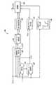
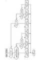
図2に示すように、制御装置30は、付加ピッチモーメント演算部36と、付加減速力演算部37と、減速力分配部38とを有する。図3に示すように、付加ピッチモーメント演算部36は、重心スリップ角演算部41と、規範ヨーレート演算部42と、前輪横力演算部43と、ステアドラッグ演算部44と、ステアドラッグ微分値演算部45と、旋回方向ゲイン設定部47と、車速ゲイン設定部48と、演算部49とを有する。 As shown in FIG. 2, the
重心スリップ角演算部41は、車速V及び前輪舵角δf(k)に基づいて、重心スリップ角β(k)を演算する。重心スリップ角β(k)は、車両1の重心を中心とした車両のスリップ角である。重心スリップ角β(k)の演算は、公知の様々な手法を適用することができ、例えば車両1の規範モデルに基づいて、下記の数式(1)に基づいて行ってもよい。
規範ヨーレート演算部42は、車速V及び前輪舵角δf(k)に基づいて規範ヨーレートγref(k)を演算する。規範ヨーレートγref(k)は、当該車両1において車速V及び前輪舵角δf(k)が定まったときに車両1に生じるべき重心を中心としたヨーレートを表している。規範ヨーレートγref(k)の演算は、公知の様々な手法を適用することができ、例えば車両1の規範モデルに基づいた下記の数式(2)を用いて行ってもよい。
前輪横力演算部43は、前輪舵角δf(k)と、車速Vと、重心スリップ角β(k)と、規範ヨーレートγref(k)と、次の数式(3)で表される車両1の規範モデルとに基づいて前輪横力FYf(k)を演算する。
ステアドラッグ演算部44は、前輪横力FYf(k)と前輪舵角δf(k)とに基づいてステアドラッグFXsd(k)を演算する。ステアドラッグは、前輪横力FYf(k)の車両1後方を向く成分、すなわち車両1のX軸(前後軸)に沿った成分であり、ステアリングドラッグやコーナリングドラッグともいわれる。ステアドラッグ演算部44は、次の数式(4)に基づいて、前輪横力FYf(k)と前輪舵角δf(k)からステアドラッグFXsd(k)を演算する。
ステアドラッグ微分値演算部45は、ステアドラッグFXsd(k)を微分することによってステアドラッグ微分値d/dt(FXsd(k))を演算する。ステアドラッグ微分値演算部45は、ステアドラッグFXsd(k)の前回値FXsd(k-1)と今回値FXsd(k)とに基づいて、次の数式(5)によってステアドラッグ微分値d/dt(FXsd(k))を演算する。
旋回方向ゲイン設定部47は、ヨーレートセンサ35によって検出された実ヨーレートγ(k)と、規範ヨーレート演算部42によって演算された規範ヨーレートγref(k)とに基づいて、旋回方向ゲインG1を設定する。旋回方向ゲイン設定部47は、実ヨーレートγ(k)及び規範ヨーレートγref(k)の符号(正負)が同じときに旋回方向ゲインG1に1を設定し、符号が異なるときに旋回方向ゲインG1に0を設定する。本実施形態では、旋回方向ゲイン設定部47は、実ヨーレートγ(k)に規範ヨーレートγref(k)を掛け、値が0以上のときに旋回方向ゲインG1に1を設定し、値が0より小さいときに旋回方向ゲインG1に0を設定する。実ヨーレートγ(k)及び規範ヨーレートγref(k)の符号が同じときは車両1が旋回状態であると判断でき、符号が異なるときは車両1に横滑りやスピンが生じている状態と判断できる。他の実施形態では、旋回方向ゲインG1の急激な変化を抑制するべく、実ヨーレートγ(k)と規範ヨーレートγref(k)とを乗じた値が0以上であるときに、乗じた値の大きさに応じて旋回方向ゲインG1の値を0から1の範囲で増加させるようにしてもよい。The turning direction gain setting
車速ゲイン設定部48は、車速Vに応じて、0から1の間で変化する車速ゲインG2を設定する。例えば、車速Vが所定の第1閾値以下の場合に車速ゲインG2が0に設定され、車速Vが第1閾値より大きくかつ所定の第2閾値より小さい場合に車速ゲインG2が0より大きく1より小さい値に設定され、車速Vが第2閾値以上の場合に車速ゲインG2が1に設定されるように構成されている。また、車速Vが第1閾値より大きくかつ所定の第2閾値より小さい場合には、車速Vの増加に応じて車速ゲインG2が比例的に増加するとよい。 The vehicle speed
図4に示すように、演算部49は、ステアドラッグ前後ジャーク演算部51と、付加前後加速度ベース値演算部52と、補正部53と、レートリミット処理部54と、ローパスフィルタ処理部55と、演算部56とを有する。ステアドラッグ前後ジャーク演算部51は、次の数式(6)に示すように、ステアドラッグ微分値d/dt(FXsd(k))を車両重量で除することによって、ステアドラッグ前後ジャークd/dt(GXsd(k))を演算する。ステアドラッグ前後ジャークd/dt(GXsd(k))は、ステアドラッグFXsd(k)によって生じる前後ジャーク(前後加加速度)である。
付加前後加速度ベース値演算部52は、ステアドラッグ前後ジャークd/dt(GXsd(k))に基づいて、車両1に付加すべき加速度のベース値(生値)である付加前後加速度ベース値GXad0(k)を演算する。付加前後加速度ベース値GXad0(k)の演算は、次の数式(7)に示すように、ステアドラッグ前後ジャークd/dt(GXsd(k))に所定の係数Kpを乗じたものを付加前後加速度ベース値GXad0(k)とする。
補正部53は、付加前後加速度ベース値GXad0(k)に、旋回方向ゲインG1及び車速ゲインG2を乗じて第1付加前後加速度補正値GXad1(k)を演算する。レートリミット処理部54は、第1付加前後加速度補正値GXad1(k)の変化率が所定の値以下となるようにレートリミット処理を行い、第1付加前後加速度補正値GXad1(k)を補正して第2付加前後加速度補正値GXad2(k)とする。第1付加前後加速度補正値GXad1(k)の変化率が所定の値以下である場合には、第2付加前後加速度補正値GXad2(k)は第1付加前後加速度補正値GXad1(k)と等しくなり、第1付加前後加速度補正値GXad1(k)の変化率が所定の値より大きい場合には第2付加前後加速度補正値GXad2(k)は第2付加前後加速度補正値GXad2(k)の前回値に対して所定の上限変化量を有する値に設定される。ローパスフィルタ処理部55は、第2付加前後加速度補正値GXad2(k)が所定の上限値以下となるように値を補正し、付加前後加速度GXadd(k)として出力する。The correction unit 53 calculates the first additional front-rear acceleration correction value G Xad1 (k) by multiplying the added front-rear acceleration base value GXad0 (k) by the turning direction gain G1 and the vehicle speed gain G2. The rate
演算部56は、付加前後加速度GXadd(k)に基づいて、次の数式(8)に基づいて、車両1に付加すべき付加ピッチモーメントMYadd(k)を演算する。
図5に示すように、前輪舵角δf(k)は中立位置を0°として、右旋回(正側とする)と左旋回(負側とする)とで値の符号が相違し、前輪舵角δf(k)に応じて発生する前輪横力FYf(k)も右旋回と左旋回とで値の符号が相違する。一方、前輪横力FYf(k)の車両1の後方を向く成分であるステアドラッグFXsd(k)は、旋回方向に関係なく常に車両1の後方を向き、常に負の値となる。ステアドラッグFXsd(k)は、前輪舵角δf(k)の絶対値の増加に応じて負側(車両1後方側)に値が増加する傾向を有する。ステアドラッグFXsd(k)の微分値であるステアドラッグ微分値d/dt(FXsd(k))は、前輪舵角δf(k)の増加時、すなわちステアリングホイール17の切り増し時に負の値となり、前輪舵角δf(k)の減少時、すなわちステアリングホイール17の切り戻し時に正の値となり、切り増し時及び切り戻し時で値の正負が異なる。そのため、ステアドラッグ微分値d/dt(FXsd(k))に基づいて前輪舵角δf(k)(ステアリングホイール17)の切り増し時及び切り戻し時を容易に判別することができる。ステアドラッグ微分値d/dt(FXsd(k))を車体重量mで除したステアドラッグ前後ジャークd/dt(GXsd(k))についても同様に、その値に基づいて前輪舵角δf(k)の切り増し時及び切り戻し時を容易に判別することができる。そのため、ステアドラッグ微分値d/dt(FXsd(k))及びステアドラッグ前後ジャークd/dt(GXsd(k))に基づいて付加ピッチモーメントMYadd(k)を設定することによって、前輪舵角δf(k)(ステアリングホイール17)の切り増し時及び切り戻し時を判別して適切に付加ピッチモーメントMYadd(k)を設定することができる。As shown in FIG. 5,the sign of the value of the front wheel steering angle δ f (k) is different between right turn (positive side) and left turn (negative side) with the neutral position as 0 °.The sign of the value of the front wheel lateral force FYf (k) generated according to the front wheel steering angle δ f (k) differs between right turn and left turn. On the other hand, steering drag FXsd a component facing the rear of the
また、規範ヨーレートγref(k)と実ヨーレートγ(k)との符号に基づいて旋回方向ゲインG1を設定するため、規範ヨーレートγref(k)と実ヨーレートγ(k)の符号が相違して車両1に横滑り(スピン)が発生していると判定される場合には、旋回方向ゲインG1が0となって付加ピッチモーメントMYadd(k)が0となり、横滑りが助長されることがない。Further, since the turning direction gain G1 is set based on the codes of the normative yaw rate γref (k) and the actual yaw rate γ (k), the codes of the normative yaw rate γref (k) and the actual yaw rate γ (k) are different. When it is determined that the
また、演算部49は、車速Vに応じて設定される車速ゲインG2に基づいて付加ピッチモーメントMYadd(k)を演算するため、車速Vが大きいほど荷重移動が大きくなる。これにより、高速でコーナーに進入するときには、より大きな制動力が発生して荷重が前輪側に移動し、旋回性が向上する。Further, since the
図2に示す付加減速力演算部37は、付加ピッチモーメントMYadd(k)に基づいて、付加ピッチモーメントMYadd(k)を発生させるために前輪4Aに加えるべき付加減速力Fadd(k)を演算する。付加減速力演算部37は、例えば次の数式(9)及び(10)に基づいて演算するとよい。
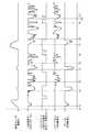
減速力分配部38は、付加減速力Fadd(k)と、ブレーキ20及びパワープラント6の状態情報とに基づいて、ブレーキ20が発生させるべきブレーキ付加減速力Fbadd(k)とパワープラント6が発生させるべきパワープラント付加減速力Fpadd(k)とを演算する。減速力分配部38は、図6に示す減速力分配処理に従ってブレーキ付加減速力Fbadd(k)とパワープラント付加減速力Fpadd(k)とを演算する。ブレーキ付加減速力Fbadd(k)及びパワープラント付加減速力Fpadd(k)は、加速側を正、減速側を負の値とする。The deceleration
減速力分配部38は、最初に、前回の付加減速力Fadd(k-1)が0であるか否かを判定する(S1)。このS1の判定により、現時点においてパワープラント6及びブレーキ20の少なくとも一方が既に付加減速力Fadd(k)に基づく減速力を発生させているか否かを確認することができる。The deceleration
減速力分配部38は、S1の判定結果がYesの場合、予め設定されたパワープラント分配不可条件が成立しているか否かを判定する(S2)。パワープラント分配不可条件は、例えばブレーキペダルが踏み込まれているか否か(すなわち、制動要求があるか否か、条件1)、パワープラント6がフューエルカット中であるか否か(条件2)、パワープラント6の冷却水の温度が所定の判定値以下であるか否か(条件3)、パワープラント6の回転数が所定の判定値以下であるか否か(条件4)、リタード継続時間が所定の判定値以上であるか否か(条件5)、リタードを禁止すべき故障が発生しているか否か(条件6)、の少なくとも1つを含むとよい。 When the determination result in S1 is Yes, the deceleration
ブレーキペダルが踏み込まれている場合(条件1が成立)、パワープラント6は既に出力を低減させているため、更に減速力を発生させることが困難である。同様に、フューエルカットが実行されている場合(条件2が成立)、パワープラント6は既に出力を低減させているため、更に減速力を発生させることが困難である。条件3〜6のいずれかが成立する場合、リタード制御を実行することができず、パワープラント6は減速力を発生させることができない。パワープラント6の冷却水の温度が所定の判定値以下の場合(条件3が成立)、不完全燃焼を防止するためにリタード制御が禁止される。パワープラント6の回転数が所定の判定値以下である場合(条件4が成立)、パワープラント6のエンジンストップを防止するためにリタード制御が禁止される。リタード継続時間が所定の判定値以上である場合(条件5が成立)、パワープラント6の排気を浄化する排気浄化触媒の温度上昇を防止するためにリタード制御が禁止される。 When the brake pedal is depressed (
減速力分配部38は、アクセルペダルセンサやエンジンECU、冷却水温センサ、エンジン回転数センサ、各種故障検知センサから信号に基づいて、パワープラント分配不可条件が成立しているか否かを判定する。本実施形態では、減速力分配部38は、上記の条件1〜6のいずれか1つが成立しているときに、パワープラント分配不可条件が成立していると判定する。他の実施形態では、減速力分配部38は、上記の条件1〜6の内、複数が成立しているときに、パワープラント分配不可条件が成立していると判定してもよい。 The deceleration
減速力分配部38は、パワープラント分配不可条件が成立している場合(S2の判定結果がYesの場合)、パワープラント付加減速力Fpadd(k)に0を設定し、ブレーキ付加減速力Fbadd(k)に付加減速力Fadd(k)を設定する(S3)。S3の処理によって、付加減速力Fadd(k)は、ブレーキ20のみによって実現される。When the power plant distribution disabling condition is satisfied (when the determination result of S2 is Yes), the deceleration force distribution unit 38sets 0 for the power plant additional deceleration force Fp add (k) and sets the brake additional deceleration force Fb.The additional deceleration force Fadd (k) is set in add (k) (S3). By the processing of S3, the additional deceleration force Fadd (k) is realized only by the
減速力分配部38は、パワープラント分配不可条件が不成立である場合(S2の判定結果がNoの場合)、付加減速力Fadd(k)の絶対値が所定の判定値Fpsh以下であるか否かを判定する(S4)。判定値Fpshは、付加減速力Fadd(k)に対してパワープラント6が発生可能な減速力の判定値として設定されており、正の値である。When the power plant distributable condition is not satisfied (when the determination result of S2 is No), the deceleration
減速力分配部38は、付加減速力Fadd(k)の絶対値が判定値Fpsh以上の場合(S4の判定結果がYesの場合)、パワープラント付加減速力Fpadd(k)に付加減速力Fadd(k)を設定し、ブレーキ付加減速力Fbadd(k)に0を設定する(S5)。S5の処理によって、付加減速力Fadd(k)は、パワープラント6のみによって実現される。When the absolute value of the additional deceleration force F add (k) is equal toor greater than the determination value Fp sh (when the determination result of S4 is Yes), the deceleration
減速力分配部38は、付加減速力Fadd(k)の絶対値が判定値Fpshより大きい場合(S4の判定結果がNoの場合)、パワープラント付加減速力Fpadd(k)に判定値Fpshの符号を負にした−Fpshを設定し、ブレーキ付加減速力Fbadd(k)に付加減速力Fadd(k)に判定値Fpshを加算した値(Fadd(k)+Fpsh)を設定する(S6)。付加減速力Fadd(k)は負の値であり、判定値Fpshは正の値であるため、Fadd(k)+Fpshの絶対値は付加減速力Fadd(k)の絶対値より小さくなる。S6の処理によって、付加減速力Fadd(k)は、パワープラント6とブレーキとによって実現される。When the absolute value of the additional deceleration force Fadd (k) islarger than the determination value Fp sh (when the determination result of S4 is No), thedeceleration force distribution unit 38 determines the power plant additional deceleration force Fp add (k). Set −Fpsh with the sign of Fpsh negative, and setthe value (F add (k) + Fpsh) obtained by adding the judgment value Fpsh to the additional deceleration force Fadd(k) to the brake additional deceleration force Fb add (k). (S6). Since the additional deceleration force Fadd (k) is a negative value and the judgment value Fpsh is a positive value,the absolute value of F add (k) + Fpsh is smaller than the absolute value of the additional deceleration force Fadd (k). .. By the processing of S6, the additional deceleration force Fadd (k) is realized by the
減速力分配部38は、S1の判定結果がNoの場合、すなわちパワープラント6及びブレーキ20の少なくとも一方が、付加減速力Fadd(k)に基づく減速力を既に発生させている場合、前回のパワープラント付加減速力Fpadd(k-1)が0であるか否かを判定する(S7)。When the determination result of S1 is No, that is, when at least one of the
減速力分配部38は、前回のパワープラント付加減速力Fpadd(k-1)が0である場合(S7の判定結果がYes)、ブレーキ付加減速力Fbadd(k)に付加減速力Fadd(k)を設定する。これにより、前回にブレーキ20のみが付加減速力Fadd(k)に基づく減速力を発生させている場合には、継続してブレーキ20のみが付加減速力Fadd(k)に基づく減速力を発生させる。Deceleration
減速力分配部38は、前回のパワープラント付加減速力Fpadd(k-1)が0でない場合(S7の判定結果がNo)、付加減速力Fadd(k)の絶対値が判定値Fpsh以下であるか否かを判定する(S9)。減速力分配部38は、付加減速力Fadd(k)の絶対値が判定値Fpsh以下の場合(S9の判定結果がYesの場合)、パワープラント付加減速力Fpadd(k)に付加減速力Fadd(k)を設定し、ブレーキ付加減速力Fbadd(k)に0を設定する(S10)。一方、減速力分配部38は、付加減速力Fadd(k)の絶対値が判定値Fpshより大きい場合(S9の判定結果がNoの場合)、パワープラント付加減速力Fpadd(k)に判定値Fpshの符号を負にした−Fpshを設定し、ブレーキ付加減速力Fbadd(k)に0を設定する(S11)。S10及びS11の処理により、前回にパワープラント6が付加減速力Fadd(k)に基づく減速力を発生させている場合には、継続してパワープラント6が付加減速力Fadd(k)に基づく減速力を発生させる。In the deceleration
減速力分配部38は、S3、S5、S6、S8、S10、S11の処理を実行した後にリターンに進み、減速力分配制御を繰り返す。 The deceleration
パワープラント6は、減速力分配部38によって設定されたパワープラント付加減速力Fpadd(k)に基づいて制御され、パワープラント付加減速力Fpadd(k)を発生させる。また、ブレーキ20は、減速力分配部38によって設定されたブレーキ付加減速力Fbadd(k)に基づいて制御され、ブレーキ付加減速力Fbadd(k)を発生させる。これにより、車両1に付加ピッチモーメントMYadd(k)に応じたピッチモーメントを発生させ、前輪4Aの荷重を大きくし、前輪横力FYf(k)を大きくして旋回性を高めることができる。The power plant 6 is controlled based on the power plant additional deceleration force Fp add (k) set by the deceleration
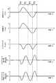
以上のように構成した制御装置30の作用及び効果について説明する。制御装置30の減速力分配部38は、図6の減速力分配処理を実行することによって、図7に示すようにパワープラント付加減速力Fpadd(k)及びブレーキ付加減速力Fbadd(k)を設定する。図7の時間T1、T2、T4、T7では、パワープラント分配不可条件が成立しているため、付加減速力Fadd(k)に基づいてブレーキ付加減速力Fbadd(k)が設定され、パワープラント付加減速力Fpadd(k)に0が設定される。時間T3、T5、T8、T10では、パワープラント分配不可条件が不成立であるため、付加減速力Fadd(k)に基づいてパワープラント付加減速力Fpadd(k)が設定され、ブレーキ付加減速力Fbadd(k)には0が設定される。なお、時間T3、T5、T8、T10から発生する付加減速力Fadd(k)の絶対値は判定値Fpsh以下であり、パワープラント付加減速力Fpadd(k)は付加減速力Fadd(k)と等しい値に設定される。このように、パワープラント分配不可条件が成立していない場合には、パワープラント6を使用して付加減速力Fadd(k)を発生させることができる。The operation and effect of the
また、時間T6及びT9では、パワープラント分配不可条件が不成立から成立に変化するが、その時点においてパワープラント6が既に減速力を発生させているため、パワープラント6が継続して減速力を発生させる。これにより、減速力を発生させる装置をパワープラント6からブレーキ20に切り替えることに起因する、減速度の変動を抑制することができる。 Further, at times T6 and T9, the power plant distributable condition changes from unsatisfied to satisfied, but since the
以上で具体的実施形態の説明を終えるが、本発明は上記実施形態に限定されることなく幅広く変形実施することができる。 Although the description of the specific embodiment is completed above, the present invention can be widely modified without being limited to the above embodiment.
1 :車両
4A :前輪
4B :後輪
6 :パワープラント
20 :ブレーキ
21 :油圧供給装置
30 :制御装置
33 :車速センサ
34 :前輪舵角センサ
35 :ヨーレートセンサ
36 :付加ピッチモーメント演算部
37 :付加減速力演算部
38 :減速力分配部
49 :演算部1:
Claims (5)
Translated fromJapanese前輪舵角を含む車両状態情報を取得する車両状態検出装置と、
前記車両状態情報に基づいて前記車両に加えるべき付加ピッチモーメントを演算する付加ピッチモーメント演算部と、
前記付加ピッチモーメントに基づいて前記車両に発生させるべき、減速側を負の値とした付加減速力を演算する減速力演算部と、
前記付加減速力と、前記ブレーキ及び前記パワープラントの状態情報とに基づいて、前記ブレーキが発生させるべきブレーキ付加減速力と前記パワープラントが発生させるパワープラント付加減速力とを演算する減速力分配部とを有し、
前記減速力分配部は、予め設定されたパワープラント分配不可条件が成立したときに、前記付加減速力に基づいて前記ブレーキ付加減速力を演算し、かつ前記パワープラント付加減速力に0を設定し、前記パワープラント分配不可条件が成立から不成立に変化しても、前記付加減速力が0になるまで前記パワープラント付加減速力を0に維持することを特徴とする車両制御装置。A vehicle control device that controls vehicle brakes and power plants.
A vehicle condition detection device that acquires vehicle condition information including the front wheel steering angle,
An additional pitch moment calculation unit that calculates an additional pitch moment to be added to the vehicle based on the vehicle state information,
A deceleration force calculation unit that calculates an additional deceleration force with the deceleration side as a negative value, which should be generated in the vehicle based on the additional pitch moment.
A deceleration force distribution unit that calculates the brake additional deceleration force to be generated by the brake and the power plant additional deceleration force generated by the power plant based on the additional deceleration force and the state information of the brake and the power plant.It has adoor,
The deceleration force distribution unit calculates the brake additional deceleration force based on the additional deceleration force and sets 0 to the power plant additional deceleration force when a preset power plant distributable condition is satisfied. The vehicle control device is characterizedin that the power plant additional deceleration force is maintained at 0 until the additional deceleration force becomes 0 even if the power plant distributable condition is changed from being satisfied to not being satisfied.
Priority Applications (3)
| Application Number | Priority Date | Filing Date | Title |
|---|---|---|---|
| JP2018240419AJP6832331B2 (en) | 2018-12-24 | 2018-12-24 | Vehicle control device |
| US16/719,312US11318945B2 (en) | 2018-12-24 | 2019-12-18 | Vehicle control system |
| CN201911308675.1ACN111361548B (en) | 2018-12-24 | 2019-12-18 | Vehicle control system |
Applications Claiming Priority (1)
| Application Number | Priority Date | Filing Date | Title |
|---|---|---|---|
| JP2018240419AJP6832331B2 (en) | 2018-12-24 | 2018-12-24 | Vehicle control device |
Publications (2)
| Publication Number | Publication Date |
|---|---|
| JP2020100320A JP2020100320A (en) | 2020-07-02 |
| JP6832331B2true JP6832331B2 (en) | 2021-02-24 |
Family
ID=71097353
Family Applications (1)
| Application Number | Title | Priority Date | Filing Date |
|---|---|---|---|
| JP2018240419AActiveJP6832331B2 (en) | 2018-12-24 | 2018-12-24 | Vehicle control device |
Country Status (3)
| Country | Link |
|---|---|
| US (1) | US11318945B2 (en) |
| JP (1) | JP6832331B2 (en) |
| CN (1) | CN111361548B (en) |
Families Citing this family (7)
| Publication number | Priority date | Publication date | Assignee | Title |
|---|---|---|---|---|
| KR20210037785A (en)* | 2019-09-27 | 2021-04-07 | 한국기술교육대학교 산학협력단 | Apparatus and method for improving ride comfort of a vehicle |
| WO2022086487A1 (en)* | 2020-10-19 | 2022-04-28 | Ford Global Technologies, Llc | Suspension system with electronic pitch stability control |
| JP7150001B2 (en)* | 2020-12-28 | 2022-10-07 | 本田技研工業株式会社 | vehicle controller |
| JP2022108414A (en) | 2021-01-13 | 2022-07-26 | 本田技研工業株式会社 | vehicle controller |
| JP7145993B2 (en)* | 2021-01-20 | 2022-10-03 | 本田技研工業株式会社 | vehicle controller |
| JP2022117642A (en)* | 2021-02-01 | 2022-08-12 | 本田技研工業株式会社 | vehicle controller |
| JP2022157610A (en) | 2021-03-31 | 2022-10-14 | 本田技研工業株式会社 | vehicle controller |
Family Cites Families (10)
| Publication number | Priority date | Publication date | Assignee | Title |
|---|---|---|---|---|
| JP4252487B2 (en)* | 2004-04-23 | 2009-04-08 | 日産自動車株式会社 | Deceleration control device |
| JPWO2006013645A1 (en)* | 2004-08-06 | 2008-05-01 | 株式会社日立製作所 | Vehicle attitude control device and method |
| JP2006177442A (en)* | 2004-12-22 | 2006-07-06 | Toyota Motor Corp | Acceleration / deceleration controller |
| JP4277915B2 (en)* | 2007-04-03 | 2009-06-10 | 株式会社デンソー | Vehicle control device |
| JP5143103B2 (en)* | 2009-09-30 | 2013-02-13 | 日立オートモティブシステムズ株式会社 | Vehicle motion control device |
| JP6255678B2 (en)* | 2013-03-01 | 2018-01-10 | 三菱自動車工業株式会社 | Control device for internal combustion engine |
| JP6112311B2 (en)* | 2014-08-11 | 2017-04-12 | マツダ株式会社 | Vehicle behavior control device |
| JP6073941B2 (en)* | 2015-02-18 | 2017-02-01 | 本田技研工業株式会社 | Vehicle travel control device |
| US10465614B2 (en)* | 2015-12-22 | 2019-11-05 | Mazda Motor Corporation | Vehicle control device |
| JP6395789B2 (en) | 2016-11-18 | 2018-09-26 | 本田技研工業株式会社 | Vehicle control device |
- 2018
- 2018-12-24JPJP2018240419Apatent/JP6832331B2/enactiveActive
- 2019
- 2019-12-18USUS16/719,312patent/US11318945B2/enactiveActive
- 2019-12-18CNCN201911308675.1Apatent/CN111361548B/enactiveActive
Also Published As
| Publication number | Publication date |
|---|---|
| JP2020100320A (en) | 2020-07-02 |
| US20200198637A1 (en) | 2020-06-25 |
| US11318945B2 (en) | 2022-05-03 |
| CN111361548A (en) | 2020-07-03 |
| CN111361548B (en) | 2023-04-07 |
Similar Documents
| Publication | Publication Date | Title |
|---|---|---|
| JP6832331B2 (en) | Vehicle control device | |
| US7489995B2 (en) | Vehicle motion stability control apparatus | |
| JP6844500B2 (en) | Vehicle behavior control device | |
| JP4886655B2 (en) | Vehicle behavior control device | |
| US11325599B2 (en) | Vehicle control system for adjusting longtitudinal motion to reduce deviation of lateral motion | |
| WO2018173302A1 (en) | Control device and steering device | |
| CN111152781B (en) | Vehicle behavior stabilization system | |
| CN114802140B (en) | Vehicle control system | |
| CN107444052B (en) | Damping force control device for vehicle | |
| JP6395789B2 (en) | Vehicle control device | |
| JP6521495B1 (en) | Vehicle behavior control device | |
| WO2018173303A1 (en) | Control device and suspension device | |
| US11958465B2 (en) | Vehicle control system | |
| US12077140B2 (en) | Vehicle control system | |
| JP2004203084A (en) | Vehicle motion control device | |
| US12358505B2 (en) | Vehicle control system | |
| US11840210B2 (en) | Vehicle control system | |
| JP5401236B2 (en) | Vehicle motion control device | |
| JP2006144569A (en) | Driving force controller for vehicle |
Legal Events
| Date | Code | Title | Description |
|---|---|---|---|
| A621 | Written request for application examination | Free format text:JAPANESE INTERMEDIATE CODE: A621 Effective date:20190726 | |
| A131 | Notification of reasons for refusal | Free format text:JAPANESE INTERMEDIATE CODE: A131 Effective date:20200915 | |
| A521 | Request for written amendment filed | Free format text:JAPANESE INTERMEDIATE CODE: A523 Effective date:20201113 | |
| TRDD | Decision of grant or rejection written | ||
| A01 | Written decision to grant a patent or to grant a registration (utility model) | Free format text:JAPANESE INTERMEDIATE CODE: A01 Effective date:20210105 | |
| A61 | First payment of annual fees (during grant procedure) | Free format text:JAPANESE INTERMEDIATE CODE: A61 Effective date:20210201 | |
| R150 | Certificate of patent or registration of utility model | Ref document number:6832331 Country of ref document:JP Free format text:JAPANESE INTERMEDIATE CODE: R150 |