JP6831349B2 - Synthetic Aperture Image Reconstruction System in Patient Interface Module (PIM) - Google Patents
Synthetic Aperture Image Reconstruction System in Patient Interface Module (PIM)Download PDFInfo
- Publication number
- JP6831349B2 JP6831349B2JP2018102529AJP2018102529AJP6831349B2JP 6831349 B2JP6831349 B2JP 6831349B2JP 2018102529 AJP2018102529 AJP 2018102529AJP 2018102529 AJP2018102529 AJP 2018102529AJP 6831349 B2JP6831349 B2JP 6831349B2
- Authority
- JP
- Japan
- Prior art keywords
- circuit
- signal
- flavor
- pim
- phase
- Prior art date
- Legal status (The legal status is an assumption and is not a legal conclusion. Google has not performed a legal analysis and makes no representation as to the accuracy of the status listed.)
- Expired - Fee Related
Links
- 239000000796flavoring agentSubstances0.000claimsdescription100
- 235000019634flavorsNutrition0.000claimsdescription98
- 238000001514detection methodMethods0.000claimsdescription48
- 238000000034methodMethods0.000claimsdescription41
- 238000006243chemical reactionMethods0.000claimsdescription18
- 239000000872bufferSubstances0.000claimsdescription13
- 230000008569processEffects0.000claimsdescription9
- 230000004044responseEffects0.000claimsdescription5
- 238000012935AveragingMethods0.000claimsdescription4
- 230000005540biological transmissionEffects0.000claimsdescription4
- 238000002592echocardiographyMethods0.000claimsdescription3
- 230000003287optical effectEffects0.000claimsdescription3
- 230000001360synchronised effectEffects0.000claimsdescription3
- 230000003750conditioning effectEffects0.000claimsdescription2
- 238000001228spectrumMethods0.000claimsdescription2
- 238000005070samplingMethods0.000description38
- 239000007787solidSubstances0.000description20
- 238000012545processingMethods0.000description17
- 238000003384imaging methodMethods0.000description16
- 230000002792vascularEffects0.000description8
- 238000004891communicationMethods0.000description7
- 238000001914filtrationMethods0.000description7
- 230000009467reductionEffects0.000description6
- 238000002604ultrasonographyMethods0.000description6
- 210000004204blood vesselAnatomy0.000description4
- 230000006870functionEffects0.000description4
- 230000002093peripheral effectEffects0.000description4
- 238000012014optical coherence tomographyMethods0.000description3
- 230000003111delayed effectEffects0.000description2
- 238000010586diagramMethods0.000description2
- 230000006872improvementEffects0.000description2
- 230000010363phase shiftEffects0.000description2
- 239000013316polymer of intrinsic microporositySubstances0.000description2
- 230000001960triggered effectEffects0.000description2
- 230000003321amplificationEffects0.000description1
- 238000003491arrayMethods0.000description1
- 210000001367arteryAnatomy0.000description1
- 230000008901benefitEffects0.000description1
- 210000004369bloodAnatomy0.000description1
- 239000008280bloodSubstances0.000description1
- 230000003139buffering effectEffects0.000description1
- 238000004364calculation methodMethods0.000description1
- 230000015556catabolic processEffects0.000description1
- 239000002131composite materialSubstances0.000description1
- 238000006731degradation reactionMethods0.000description1
- 238000013461designMethods0.000description1
- 239000006185dispersionSubstances0.000description1
- 235000013399edible fruitsNutrition0.000description1
- 210000003743erythrocyteAnatomy0.000description1
- 230000002349favourable effectEffects0.000description1
- 238000001727in vivoMethods0.000description1
- 238000002608intravascular ultrasoundMethods0.000description1
- 238000012986modificationMethods0.000description1
- 230000004048modificationEffects0.000description1
- 238000003199nucleic acid amplification methodMethods0.000description1
- 239000013307optical fiberSubstances0.000description1
- 230000035945sensitivityEffects0.000description1
- 238000000638solvent extractionMethods0.000description1
- 230000003595spectral effectEffects0.000description1
- 230000007704transitionEffects0.000description1
Images


Classifications
- A—HUMAN NECESSITIES
- A61—MEDICAL OR VETERINARY SCIENCE; HYGIENE
- A61B—DIAGNOSIS; SURGERY; IDENTIFICATION
- A61B8/00—Diagnosis using ultrasonic, sonic or infrasonic waves
- A61B8/12—Diagnosis using ultrasonic, sonic or infrasonic waves in body cavities or body tracts, e.g. by using catheters
- A—HUMAN NECESSITIES
- A61—MEDICAL OR VETERINARY SCIENCE; HYGIENE
- A61B—DIAGNOSIS; SURGERY; IDENTIFICATION
- A61B5/00—Measuring for diagnostic purposes; Identification of persons
- A61B5/0059—Measuring for diagnostic purposes; Identification of persons using light, e.g. diagnosis by transillumination, diascopy, fluorescence
- A61B5/0062—Arrangements for scanning
- A61B5/0066—Optical coherence imaging
- A—HUMAN NECESSITIES
- A61—MEDICAL OR VETERINARY SCIENCE; HYGIENE
- A61B—DIAGNOSIS; SURGERY; IDENTIFICATION
- A61B5/00—Measuring for diagnostic purposes; Identification of persons
- A61B5/0059—Measuring for diagnostic purposes; Identification of persons using light, e.g. diagnosis by transillumination, diascopy, fluorescence
- A61B5/0082—Measuring for diagnostic purposes; Identification of persons using light, e.g. diagnosis by transillumination, diascopy, fluorescence adapted for particular medical purposes
- A61B5/0084—Measuring for diagnostic purposes; Identification of persons using light, e.g. diagnosis by transillumination, diascopy, fluorescence adapted for particular medical purposes for introduction into the body, e.g. by catheters
- A—HUMAN NECESSITIES
- A61—MEDICAL OR VETERINARY SCIENCE; HYGIENE
- A61B—DIAGNOSIS; SURGERY; IDENTIFICATION
- A61B8/00—Diagnosis using ultrasonic, sonic or infrasonic waves
- A61B8/08—Clinical applications
- A61B8/0891—Clinical applications for diagnosis of blood vessels
- A—HUMAN NECESSITIES
- A61—MEDICAL OR VETERINARY SCIENCE; HYGIENE
- A61B—DIAGNOSIS; SURGERY; IDENTIFICATION
- A61B8/00—Diagnosis using ultrasonic, sonic or infrasonic waves
- A61B8/52—Devices using data or image processing specially adapted for diagnosis using ultrasonic, sonic or infrasonic waves
- A61B8/5207—Devices using data or image processing specially adapted for diagnosis using ultrasonic, sonic or infrasonic waves involving processing of raw data to produce diagnostic data, e.g. for generating an image
- G—PHYSICS
- G01—MEASURING; TESTING
- G01S—RADIO DIRECTION-FINDING; RADIO NAVIGATION; DETERMINING DISTANCE OR VELOCITY BY USE OF RADIO WAVES; LOCATING OR PRESENCE-DETECTING BY USE OF THE REFLECTION OR RERADIATION OF RADIO WAVES; ANALOGOUS ARRANGEMENTS USING OTHER WAVES
- G01S15/00—Systems using the reflection or reradiation of acoustic waves, e.g. sonar systems
- G01S15/88—Sonar systems specially adapted for specific applications
- G01S15/89—Sonar systems specially adapted for specific applications for mapping or imaging
- G01S15/8906—Short-range imaging systems; Acoustic microscope systems using pulse-echo techniques
- G01S15/8909—Short-range imaging systems; Acoustic microscope systems using pulse-echo techniques using a static transducer configuration
- G01S15/8915—Short-range imaging systems; Acoustic microscope systems using pulse-echo techniques using a static transducer configuration using a transducer array
- G01S15/892—Short-range imaging systems; Acoustic microscope systems using pulse-echo techniques using a static transducer configuration using a transducer array the array being curvilinear
- G—PHYSICS
- G01—MEASURING; TESTING
- G01S—RADIO DIRECTION-FINDING; RADIO NAVIGATION; DETERMINING DISTANCE OR VELOCITY BY USE OF RADIO WAVES; LOCATING OR PRESENCE-DETECTING BY USE OF THE REFLECTION OR RERADIATION OF RADIO WAVES; ANALOGOUS ARRANGEMENTS USING OTHER WAVES
- G01S15/00—Systems using the reflection or reradiation of acoustic waves, e.g. sonar systems
- G01S15/88—Sonar systems specially adapted for specific applications
- G01S15/89—Sonar systems specially adapted for specific applications for mapping or imaging
- G01S15/8906—Short-range imaging systems; Acoustic microscope systems using pulse-echo techniques
- G01S15/8997—Short-range imaging systems; Acoustic microscope systems using pulse-echo techniques using synthetic aperture techniques
- H—ELECTRICITY
- H03—ELECTRONIC CIRCUITRY
- H03K—PULSE TECHNIQUE
- H03K19/00—Logic circuits, i.e. having at least two inputs acting on one output; Inverting circuits
- H03K19/02—Logic circuits, i.e. having at least two inputs acting on one output; Inverting circuits using specified components
- H03K19/173—Logic circuits, i.e. having at least two inputs acting on one output; Inverting circuits using specified components using elementary logic circuits as components
- H03K19/177—Logic circuits, i.e. having at least two inputs acting on one output; Inverting circuits using specified components using elementary logic circuits as components arranged in matrix form
- H03K19/17724—Structural details of logic blocks
- H03K19/17728—Reconfigurable logic blocks, e.g. lookup tables
Landscapes
- Health & Medical Sciences (AREA)
- Life Sciences & Earth Sciences (AREA)
- Physics & Mathematics (AREA)
- Engineering & Computer Science (AREA)
- Radar, Positioning & Navigation (AREA)
- Remote Sensing (AREA)
- Heart & Thoracic Surgery (AREA)
- General Health & Medical Sciences (AREA)
- Veterinary Medicine (AREA)
- Public Health (AREA)
- Animal Behavior & Ethology (AREA)
- Biophysics (AREA)
- Pathology (AREA)
- Biomedical Technology (AREA)
- Surgery (AREA)
- Medical Informatics (AREA)
- Molecular Biology (AREA)
- Radiology & Medical Imaging (AREA)
- Nuclear Medicine, Radiotherapy & Molecular Imaging (AREA)
- Acoustics & Sound (AREA)
- Mathematical Physics (AREA)
- General Physics & Mathematics (AREA)
- Computer Networks & Wireless Communication (AREA)
- Computing Systems (AREA)
- Computer Hardware Design (AREA)
- General Engineering & Computer Science (AREA)
- Computer Vision & Pattern Recognition (AREA)
- Vascular Medicine (AREA)
- Ultra Sonic Daignosis Equipment (AREA)
- Endoscopes (AREA)
- Theoretical Computer Science (AREA)
Description
Translated fromJapanese本開示は、一般的に生体内の血管内超音波(IVUS)撮像に関し、特に超音波トランスデューサのアレイを備えたソリッドステートカテーテルで採取したデータから画像を得るIVUS患者インターフェースモジュール(PIM)に関する。 The present disclosure relates generally to in vivo endovascular ultrasound (IVUS) imaging, and particularly to the IVUS patient interface module (PIM), which obtains images from data taken with a solid state catheter equipped with an array of ultrasound transducers.
血管内超音波(IVUS)撮像は、人体内の動脈などの病変血管の診断ツールとして介入心臓病学において、処置が必要かの判定、介入のガイドおよび/またはその有効性の評価をするために広く使用されている。IVUS撮像では、意図する血管の画像を作成するのに超音波エコーを使用する。超音波はほとんどの組織および血液を容易に通過するが、組織構造(血管壁の種々の層など)、赤血球および意図する他の特徴から生じる不連続部から部分的に反射する。患者インターフェースモジュール(PIM)を介してIVUSソリッドステートカテーテルに接続したIVUS撮像システムは、受信した超音波エコーを処理して、ソリッドステートカテーテルを配置した血管の断面像を生成する。 Intravascular ultrasound (IVUS) imaging is an intervention as a diagnostic tool for diseased blood vessels such as arteries in the human body. In cardiology, to determine if treatment is necessary, guide intervention and / or evaluate its effectiveness. Widely used. IVUS imaging uses ultrasound echoes to create images of the intended blood vessels. Ultrasound easily passes through most tissues and blood, but is partially reflected from tissue structures (such as various layers of the vessel wall), red blood cells, and discontinuities resulting from other intended features. An IVUS imaging system connected to an IVUS solid-state catheter via a patient interface module (PIM) processes the received ultrasound echo to produce a cross-sectional image of the vessel in which the solid-state catheter is placed.
既存のソリッドステートIVUSカテーテルでは、データを獲得するのに広帯域幅が必要であること、大量のデータを格納するための高記憶装置が必要であることおよび多量の計算が必要であることなど、システムが複雑であるが、有用な診断情報が得られる。したがって、簡単なシステムを用いて、血管の状態についてのより貴重な洞察を得るために画像品質を高める必要がある。 Existing solid-state IVUS catheters require a wide bandwidth to acquire data, a high storage capacity to store large amounts of data, and a large amount of computation. Is complicated, but useful diagnostic information can be obtained. Therefore, simple systems need to be used to enhance image quality to gain more valuable insights into the condition of blood vessels.
したがって、コンパクトで効率的な回路構成および血管内超音波システムに使用されるソリッドステートIVUSカテーテルに接続するための電気的インターフェースを提供するための改善した装置、システムおよび方法がまだ必要とされている。 Therefore, there is still a need for improved equipment, systems and methods to provide compact and efficient circuit configurations and electrical interfaces for connecting to solid-state IVUS catheters used in endovascular ultrasound systems. ..
本明細書で開示される実施態様によれば、再構成フィールドプログラマブルゲートアレイ(FPGA)回路は、直交内部調整回路と;バッファ回路と;再構成エンジン回路とを備えており、前記再構成エンジン回路は信号の位相を測定する回路と;フレーバー補間回路とを備えており、信号の位相を測定する回路は前記信号の中心周波数の各サイクルについての2つの複素数を形成するデジタル化点を含んでいる。 According to an embodiment disclosed herein, a reconfigured field programmable gate array (FPGA) circuit comprises a quadrature internal adjustment circuit; a buffer circuit; and a reconfigured engine circuit, said reconfigured engine circuit. Equipped with a circuit for measuring the phase of the signal; a flavor interpolation circuit; the circuit for measuring the phase of the signal contains digitizing points forming two complex numbers for each cycle of the central frequency of the signal. ..
本明細書で開示される実施態様によれば、組織画像を採取するためのシステムは、患者インターフェースモジュール(PIM)を備え、前記PIMはパルス送信器回路と;アナログ/デジタル変換回路と;再構成FPGA回路と;遠位端付近に検出ヘッドを有するカテーテルであって、前記検出ヘッドがトランスデューサ要素アレイを備えているカテーテルとを備えており、前記再構成FPGA回路は直交内部調整回路と;バッファ回路と;再構成エンジン回路とを備えており、再構成エンジン回路は信号の位相を測定するための回路と;フレーバー補間回路とを備えており、信号の位相を測定するための前記回路は前記信号の中心周波数の各サイクルの2つの複素数を形成するデジタル化点を含むことができる。 According to embodiments disclosed herein, the system for taking tissue images comprises a patient interface module (PIM), said PIM with a pulse transmitter circuit; with an analog-to-digital converter circuit; An FPGA circuit; a catheter having a detection head near the distal end, wherein the detection head comprises a catheter with a transducer element array, and the reconstructed FPGA circuit is an orthogonal internal adjustment circuit; a buffer circuit. The reconstructed engine circuit includes a circuit for measuring the phase of the signal and; the flavor interpolation circuit is provided, and the circuit for measuring the phase of the signal is the signal. It can contain digitizing points that form two complex numbers for each cycle of the central frequency of.
ある実施態様によれば、画像再構成方法は、複数のトランスデューサからの信号を受信すること;アナログ/デジタル変換器において前記信号を処理すること;複素対数におけるデータ点を整理すること;アキュミュレーターを用いて複素対数の位相を調整すること;フレーバー間の複素データ点を補間することを備えることができる。 According to one embodiment, the image reconstruction method is to receive signals from multiple transducers; to process the signals in an analog / digital converter; to organize data points in complex logarithm; to an accumulator. Adjusting the phase of the complex logarithm using; can be provided to interpolate complex data points between flavors.
本開示のこれらおよび他の実施態様を、以下において添付図面を参照しながらさらに詳細に説明する。 These and other embodiments of the present disclosure will be described in more detail below with reference to the accompanying drawings.
図面において、同じ参照番号の要素は同じまたは類似の機能を有している。 In drawings, elements with the same reference number have the same or similar functionality.
本開示の原理を理解しやすくする目的で、図面に示した実施態様に言及し、特定の用語を用いて具体的に説明する。しかしながら、それらは本開示の範囲を限定するものではない。記載の装置、システムおよび方法に対するいずれの変更およびさらなる修正、ならびに本開示の原理のさらなる応用は、開示に関係する当業者により通常おこなわれているように、十分に想定され、本開示内に含まれる。特に、1つの実施態様に関して説明される特徴、構成要素および/または工程は、本開示の他の実施態様に関して説明される特徴、構成要素および/または工程と組み合わせることができる。しかしながら、簡潔とするために、これらの組み合わせの非常に多くの重複するところは、別個には説明しない。 For the purpose of facilitating the understanding of the principles of the present disclosure, the embodiments shown in the drawings will be referred to and will be specifically described using specific terms. However, they do not limit the scope of this disclosure. Any changes or further modifications to the devices, systems and methods described, as well as further applications of the principles of this disclosure, are well assumed and included within this disclosure, as would normally be made by those skilled in the art relating to the disclosure. Is done. In particular, the features, components and / or steps described for one embodiment can be combined with the features, components and / or steps described for other embodiments of the present disclosure. However, for the sake of brevity, the numerous overlaps of these combinations are not described separately.
本明細書に開示されている実施態様によるIVUSソリッドステートカテーテルにおいて、複数の超音波トランスデューサが検出ヘッド付近に位置する。本明細書で開示されているソリッドステートカテーテルまたはソリッドステート患者インターフェースモジュール(PIM)は、撮像を容易にするためにトランスデューサを物理的に回転することを必要としないカテーテルまたはPIMとして理解される。さらに、ある実施態様によれば、ソリッドステートカテーテルまたはソリッドステートPIMなどのソリッドステートコンポーネントは、互いに独立して分離または交換できる部品のない、シングルピース製コンポーネントを備えていてもよい。検出ヘッドを、可撓性ドライブシャフトの先端付近のカテーテルの遠位端に配置する。ある実施態様によれば、ドライブシャフトは、意図する血管に挿入されるプラスチックシース内部に位置してもよい。プラスチックシースは、血管組織をカテーテル内のワイヤから保護し、超音波信号が自由に検出ヘッドから組織内に伝搬し、戻ることを可能とする。互いに隣接する超音波トランスデューサ群は、トランスデューサを互いに固定位相で刺激したときに合成開口を形成してもよい。合成開口は、検出ヘッドの側部に位置し、カテーテルの長尺軸から半径方向に外側に向いている。トランスデューサは、異なる焦点深度を有する超音波ビーム群を照射した各点での種々の組織構造から反射した戻りエコーを聞き取る。これにより、IVUS像におけるAスキャンが形成される。隣接するトランスデューサまたは開口群を順次選択することにより、検出ヘッドの全周をカバーして、カテーテル周囲のAスキャンを収集してもよい。したがって、方位方向において約360°検出ヘッドを包囲する血管組織をカバーする2D画像(Bスキャン)を、Aスキャンの収集から形成してもよい。 In the IVUS solid-state catheter according to the embodiments disclosed herein, multiple ultrasonic transducers are located near the detection head. The solid-state catheter or solid-state patient interface module (PIM) disclosed herein is understood as a catheter or PIM that does not require physical rotation of the transducer to facilitate imaging. Further, according to certain embodiments, solid-state components such as solid-state catheters or solid-state PIMs may include single-piece components without components that can be separated or replaced independently of each other. The detection head is placed at the distal end of the catheter near the tip of the flexible drive shaft. According to certain embodiments, the drive shaft may be located inside a plastic sheath that is inserted into the intended blood vessel. The plastic sheath protects the vascular tissue from the wires in the catheter, allowing the ultrasonic signal to freely propagate and return from the detection head into the tissue. A group of ultrasonic transducers adjacent to each other may form a synthetic aperture when the transducers are stimulated in a fixed phase with each other. The synthetic opening is located on the side of the detection head and points radially outward from the long axis of the catheter. The transducer hears return echoes reflected from different tissue structures at each point irradiated with ultrasonic beam groups with different depths of focus. This forms an A scan in the IVUS image. A scan around the catheter may be collected to cover the entire circumference of the detection head by sequentially selecting adjacent transducers or aperture groups. Therefore, a 2D image (B scan) covering the vascular tissue surrounding the approximately 360 ° detection head in the directional direction may be formed from the collection of the A scans.
Aスキャンにより、検出ヘッドの中心にある放射状線に沿った血管組織の一次元(1D)情報が得られる。最深焦点距離が検出ヘッドにおける合成開口により可能である限り、Aスキャンは検出素子から血管組織に延びる。IVUS撮像システムは、検出ヘッドの周囲の一連の数百または数千のAスキャンラインから、血管断面の二次元表示させる。画像を正確なものとするために、カテーテルの長尺軸から半径方向に延びている複数のAラインスキャンを使用して、連続2D表示をアセンブルする。これには、複雑なハードウエア管理が必要であり、データ処理速度およびバンド幅要件について大きな負担となる。例えば、ある実施態様によれば、512または1024以下のAスキャンを、血管組織のスムーズな2D画像を形成するために、検出ヘッドの周囲付近に使用してもよい。本明細書に開示されている画像再構成システムの実施態様によれば、減少したAスキャン数を使用して正確なIVUS画像を得てもよい。 The A scan provides one-dimensional (1D) information of the vascular tissue along the radial line in the center of the detection head. As long as the deepest focal length is possible due to the synthetic aperture in the detection head, the A scan extends from the detection element to the vascular tissue. The IVUS imaging system provides a two-dimensional display of a vessel cross section from a series of hundreds or thousands of A scanlines around a detection head. To make the image accurate, multiple A-line scans extending radially from the long axis of the catheter are used to assemble a continuous 2D display. This requires complex hardware management and is a heavy burden on data processing speed and bandwidth requirements. For example, according to certain embodiments, an A scan of 512 or 1024 or less may be used near the perimeter of the detection head to form a smooth 2D image of vascular tissue. According to embodiments of the image reconstruction system disclosed herein, the reduced number of A scans may be used to obtain accurate IVUS images.
本明細書と一致するある実施態様によれば、ソリッドステートIVUSカテーテルから画像を生成するのに使用される合成開口再構成システムの構成が提供される。この構成によれば、効率的な画像再構成アルゴリズムが得られ、画像品質を犠牲にすることなくハードウエアの複雑性を減少できる。一般的に、本明細書に開示されている回路構成およびシステムは、「画像再構成」システムと称することができる。本明細書で開示されている画像再構成システムの複雑性の減少(および電力損)は、電流データ処理構成と比較して、16倍以上であることができる。この複雑性の減少により、画像再構成システムを本明細書で開示されているソリッドステートPIM内に配置するなどのシステム分割についての新たな可能性が高まる。 According to one embodiment consistent with this specification, a configuration of a synthetic aperture reconstruction system used to generate an image from a solid state IVUS catheter is provided. This configuration provides an efficient image reconstruction algorithm and can reduce hardware complexity without sacrificing image quality. Generally, the circuit configurations and systems disclosed herein can be referred to as "image reconstruction" systems. The reduction in complexity (and power loss) of the image reconstruction system disclosed herein can be 16-fold or greater as compared to the current data processing configuration. This reduction in complexity opens up new possibilities for system partitioning, such as placing the image reconstruction system within the solid-state PIM disclosed herein.
図1は、本開示の実施態様によるIVUS撮像システム100を示す。ある実施態様によれば、IVUS撮像システム100は、複数の超音波トランスデューサを有する検出ヘッド150を備えた撮像システムである。検出ヘッド150における複数の超音波トランスデューサは、カテーテル102の長尺軸(図1におけるZ軸)に集中して周囲に沿って配置されたトランスデューサ要素(例えば、16、32、64、96、128または他の好適な数)のアレイを形成してもよい。ある実施態様によれば、IVUS撮像システムは、ソリッドステートIVUSカテーテル102と、患者インターフェースモジュール(PIM)104と、IVUS制御システム106と、IVUS制御装置106により生成したIVUS画像を表示するモニター108とを備えている。ソリッドステートカテーテル102は、ある実施態様によれば、遠位端付近に検出ヘッド150を備えている。ある実施態様によれば、ソリッドステートカテーテル102の一部分は、検出ヘッド150を越えて延びて、ソリッドステートカテーテル102の先端を形成してもよい。PIM104は、適切なインターフェース仕様を実行して、ソリッドステートカテーテル102を支持する。ある実施態様によれば、PIM104は、一連の送信トリガー信号と制御波形を生成して検出ヘッド150における超音波トランスデューサの操作を調整する。 FIG. 1 shows an
本明細書に開示されている実施態様による画像再構成システムは、ソリッドステートPIM104に組み込むのに十分な程度にコンパクトである。したがって、ある実施態様によるIVUS撮像システム100は、複数の周辺装置をホスティングする「ハブ」として動作する汎用制御システム106を備えていてもよい。各周辺装置は、ソリッドステートPIM104などのそれ自体の特定用途向けインターフェースを取り付けて有していてもよい。周辺PIMは、2D再構成画像および/または他のデータを「ハブ」制御システム106に提供して、画像または他のデータを表示および/またはより詳細な画像/データ処理をおこなうようにしてもよい。 The image reconstruction system according to the embodiments disclosed herein is compact enough to be incorporated into the
本明細書に開示されている実施態様による再構成システムは、より高頻度で動作するトランスデューサのより大きなアレイを備えた検出ヘッド150を収容している。例えば、ある実施態様によれば、96〜128までのトランスデューサ要素を有するアレイを備えていてもよい。このようなトランスデューサ要素は、より多数のトランスデューサ要素により空間分解能を高め、IVUS画像品質を改善してもよい。さらに、本明細書に開示されている実施態様によれば、より高頻度で検出ヘッド150においてトランスデューサアレイを動作させることができる。 The reconstruction system according to the embodiments disclosed herein accommodates a
検出ヘッド150におけるトランスデューサ要素のアレイは、超音波信号を、PIM104からトリガー信号を受信した後に意図する組織に送信する。また、検出ヘッド150における超音波トランスデューサは、組織から受信したエコー信号を、PIM104により処理される電気信号に変換する。また、PIM104は、高圧および低圧DC電源を供給して、IVUSソリッドステートカテーテル102の動作をサポートする。ある実施態様によれば、PIM104は、DC電圧を、検出ヘッド150においてトランスデューサを駆動する回路に供給する。 The array of transducer elements in the
また、図1は、Z軸をソリッドステートカテーテル102の長手方向に沿って配向した3次元(3D)座標系XYZを示す。図1に一致する座標軸を、本開示全体を通じて使用する。当業者には、座標軸の特定の選択は本開示と一致する実施態様を限定するものではないことが分かるであろう。 FIG. 1 also shows a three-dimensional (3D) coordinate system XYZ with the Z axis oriented along the longitudinal direction of the
制御システム「ハブ」を有するIVUSシステム100の実施態様によれば、複数のソリッドステートPIM104は、制御システム106において共通ハードウエアを共有してもよい。ある実施態様によれば、様式特異的ハードウエアは、周辺ソリッドステートPIM104に位置させてもよい。このようなシステム構成は、「ハブおよびスポーク」システムと称することができる。ある実施態様によれば、制御システム106は、ディスプレイ108および、種々の機器様式に共通のユーザーインターフェース要素を管理する。さらに、本明細書に開示されている画像再構成システムは、ある実施態様によれば、PIM104における各機器の様式に特異的である。本開示と一致する実施態様によれば、ソリッドステートPIM104からホスト制御システム106に直接、使用可能なデータ速度でデジタルフォーマットにおいて、再構成Aスキャンイメージデータを供給することができる。制御システム106において、Aスキャンイメージデータを、2D組織画像(例えば、断面画像)としてスキャン変換および表示する。 According to an embodiment of the
図2は、本開示のある実施態様による、IVUS撮像システム100に使用される患者インターフェースモジュール(PIM)104の部分図である。図2は、再構成フィールドプログラマブルゲートアレイ(FPGA)回路250を備えて、アナログ/デジタル変換器(ADC)回路216により提供されるデジタル信号から、コミュニケーションプロトコル回路218に画像再構成データを提供するPIM104をより詳細に示す。ある実施態様によれば、再構成システムは、再構成FPGA250に設けられる。FPGA250は、データおよびコマンドを保存する記憶回路と、保存されたデータを用いてコマンドを実施するプロセッサ回路と、ADC回路216から受信したデータとを備えている。ある実施態様によれば、FPGA250は、ADC回路216により提供されるデータを一時的に保存するためのバッファメモリを備え、一方、プロセッサ回路は異なるデータ部分に関連する操作を実施する。 FIG. 2 is a partial view of the patient interface module (PIM) 104 used in the
図2は、テレスコープ122に嵌合するコネクタ118によりソリッドステートPIM104に取り付けたシャフト114を示す。テレスコープ122は、ソリッドステートカテーテル102の長さを調整可能にしている。また、PIM104は、パルス送信器回路212を備えていて、複数のパルス信号223を検出ヘッド150におけるトランスデューサに提供する。検出ヘッド150におけるトランスデューサは、電気信号224を受信増幅回路214に送信する。電気信号224は、受信増幅器214により増幅される。ある実施態様によれば、電気信号224は、検出ヘッド150におけるトランスデューサにより検出される血管組織からのエコー応答を含むアナログ信号である。アナログ/デジタル変換器(ADC)216は増幅器214からの増幅信号をデジタル信号に変換し、その信号はPIM104からIVUS制御システム106に通信プロトコル回路218により転送される。 FIG. 2 shows a shaft 114 attached to the
クロック/タイミング回路200は、トランスミッタタイミング信号222をパルス送信器212に提供し、安定なシステムクロックを用いてデジタル化信号226をADC回路216に提供する。ある実施態様によれば、信号222および226は互いに同期している。したがって、ある実施態様によれば、トランスミッタタイミング信号222およびデジタル化信号226は同じ位相を有しているか、またはそれらの相対位相はやがてクロック/タイミング回路200の分解能内に固定される。ある実施態様によれば、クロック/タイミング回路200は、位相ロックループ(PLL)また周波数ロックループ(FLL)を備えており、互いの有理分数である周波数を有する信号222および226を生成する。 The clock / timing circuit 200 provides the
本開示に一致する実施態様によれば、検出ヘッド150において異なる種類のトランスデューサ、例えば、従来のPZT装置、圧電微細加工超音波トランスデューサ(PMUT)装置、容量性微細加工超音波トランスデューサ(CMUT)装置および/またはそれらの組み合わせを備えることができる。ある実施態様によれば、クロック/タイミング回路200および再構成FPGA250は、血管内光学コヒレントトモグラフィ(OCT)撮像などの光学的手法を用いたPIM104の様式に含まれる。OCT撮像において、トランスデューサは、光ファイバー、フィルター要素、またはある種の他のスペクトル分散光学コンポーネントおよび光検出器を備えることができる。 According to embodiments consistent with the present disclosure, different types of transducers in the
ある実施態様によれば、再構成FPGA250は、外部メモリを用いて収集したデータをPIM104に保存してもよい。再構成FPGA250のある実施態様によれば、再構成FPGA250に備えられたメモリ回路がデータ処理操作をおこなうのに十分なように、簡略化したデータ処理スキームを使用する。したがって、ある実施態様によれば、減少した外部リンク数を有するソリッドステートPIM104は、ソリッドステートIVUSカテーテル102を支持する。ある実施態様によれば、PIM104は、各々が中心周波数が約20MHz(1MHz=106Hz)、最大30MHzで動作する128以下のトランスデューサ要素を備えた検出ヘッド150を有するソリッドステートカテーテル102を支持する。According to one embodiment, the reconfigured
ある実施態様によれば、PIM104における再構成FPGA250は、異なるAスキャンラインの間の補間操作を含むグレイスケールAスキャンを生成するように構成される。スキャン変換および表示は、IVUS制御システム106においておこなわれる。ある実施態様によれば、Aスキャンラインのグレイスケール演算により、複数の密集したAスキャンラインからのデータを結合する。Aスキャンラインにおけるデータ点の大きさを、アキュムレータおよび最小値フィルタリングと最大値フィルタリングを用いた中央値フィルタリングを用いて平均する。グレイスケール演算は、平均大きさ値の対数スケールを形成することを含む。グレイスケール演算で得られる対数値は、瓶に分布され、一定カラーレベルが各瓶に割り当てられ、Aスキャンにより形成された2D画像における各点について「グレイスケール」値を形成する。ある実施態様によれば、ネイティブベースバンドAスキャンデータはPIM104においておこなわれ、Aスキャン補間およびグレイスケール変換はIVUS制御システム106においておこなわれる。 According to one embodiment, the reconstructed
ある実施態様によれば、通信プロトコル回路218は、IVUS制御システム106に対して相対的に低帯域幅のリンクを使用する。例えば、ある実施態様によれば、通信プロトコル回路218とIVUS制御システム106との間で8〜12メガバイト/秒の通信帯域幅を使用する。PIM104とIVUS制御システム106との間のリンクについて低帯域幅を用いた実施態様は、「ハブおよびスポーク」システム構成に好適である。実際に、IVUS制御システム106における広帯域幅通信プロトコル回路は、多数のPIM104(各々が低通信帯域幅要件を有する)に対応することができる。 According to one embodiment, the communication protocol circuit 218 uses a link with a relatively low bandwidth relative to the
図3は、ある実施態様による、検出ヘッド150および超音波ビームを生成するトランスデューサ要素151−1、151−2、151−3、151−4および151−5(まとめてトランスデューサ要素151と称する)のアレイの部分図を示す。ある実施態様によれば、超音波トランスデューサ151は、カテーテル102から放射状に外側に超音波ビーム320−1、320−2または320−3(まとめてビーム320と称する)を照射する合成開口を形成する。ある実施態様によれば、合成開口は、検出ヘッド150におけるトランスデューサ要素群を同時にトリガーするか、または同相でトリガーすることにより生成する。さらに、ある実施態様によれば、検出ヘッド150における合成開口は、トランスデューサ要素群を互いの間で特定の位相差でトリガーするときに超音波ビームを生成する。 FIG. 3 shows a
合成開口におけるトランスデューサ要素151の各々の間の位相差は、超音波ビームが事前に選択された焦点ゾーン310−1、310−2または310−3(まとめて焦点ゾーン310と称する)に集中するように選択される。図3には3つの焦点ゾーン310が示されているが、当業者には、より多くの焦点ゾーン310を選択される各方向に使用できることが分かるであろう。ある実施態様によれば、各Aスキャンラインについて、10、16、20またはそれ以上の焦点ゾーンを使用してもよい。ある実施態様によれば、単一の焦点ゾーンまたは2つの焦点ゾーン310を使用してもよい。焦点ゾーン310を画定する合成開口におけるトランスデューサ要素151間の位相差は、好適遅延トリガー信号を各トランスデューサ151に供給することにより、電子的に生成してもよい。焦点ゾーン310を形成するために時間遅延させた電子的トリガーパルスの配置は、「電子レンズ」と称される。電子レンズはクロック/タイミング回路200およびパルス送信回路212に作成してもよい(図2参照)。 The phase difference between each of the transducer elements 151 in the synthetic aperture is such that the ultrasonic beam is focused in a preselected focal zone 310-1, 310-2 or 310-3 (collectively referred to as focal zone 310). Is selected for. Although three focal zones 310 are shown in FIG. 3, those skilled in the art will appreciate that more focal zones 310 can be used in each of the selected directions. According to certain embodiments, 10, 16, 20 or more focal zones may be used for each A scanline. According to certain embodiments, a single focal zone or two focal zones 310 may be used. The phase difference between the transducer elements 151 at the synthetic aperture defining the focal zone 310 may be generated electronically by supplying a suitable delay trigger signal to each transducer 151. The arrangement of the electronic trigger pulses time-delayed to form the focal zone 310 is referred to as the "electronic lens". The electronic lens may be created in the clock / timing circuit 200 and the pulse transmission circuit 212 (see FIG. 2).
ある実施態様によれば、合成開口におけるトランスデューサ151間の位相差は、超音波ビームが半径方向を中心として所定の方位角φで生成されるように選択される。事前に選択した方向を、「フレーバー」と称することができる。例えば、半径方向は、要素151−3に対応する合成開口の中央部における検出ヘッド150の断面の曲率に対して垂直な方向として定義できる(図1におけるX軸)。したがって、トランスデューサ151間の相対位相を調整して、超音波は半径方向330−1に沿って焦点ゾーン320に集めることができる。ある実施態様によれば、要素151間の相対位相を調整することにより、超音波ビームは、方位方向Δφ2に沿った「フレーバー」330−2に沿って形成される。方位方向Δφ2は、2つの隣接するトランスデューサ151間に形成される角度Δφ3の実質的に半分の角度に対する。ある実施態様によれば、角度Δφ3は0.1ラジアンであることができ、したがって、角度Δφ2は約0.05ラジアンであることができる。半径方向330−1(Δφ=0)に沿ったAスキャンは、ベースバンドAスキャンと称することができる。According to one embodiment, the phase difference between the transducers 151 at the synthetic aperture is selected such that the ultrasonic beam is generated at a predetermined azimuth angle φ about the radial direction. The preselected direction can be referred to as the "flavor". For example, the radial direction can be defined as the direction perpendicular to the curvature of the cross section of the
本明細書に開示されている実施態様によれば、焦点およびフレーバー情報を保存するコンパクトで正確な方法が提供される。複数の焦点ゾーン310および複数のフレーバーに基づくスキームは、合成開口内の各トランスデューサ要素151についての保存位相情報に依存する。位相値は、場合によっては、Aスキャンに使用される異なる焦点ゾーンに沿って各フレーバーについて保存される。例えば、フレーバー330−1における要素151−1からの音響フロントと要素151−2からの音響フロントとの間の相対位相は、線330−1(X軸)に沿った点での検出ヘッド150からの距離fを中心とする焦点ゾーンについての値(x−f)2に依存する。要素151−1からの音響フロントと要素151−2からの音響フロントとの間の相対位相は、フレーバー330−2について、(x’−f)2値との関係でも異なる。ここでx’はX軸に対して角度Δφ2をなす線に沿った検出ヘッド150からの距離である。According to the embodiments disclosed herein, a compact and accurate method of storing focus and flavor information is provided. Schemes based on multiple focal zones 310 and multiple flavors depend on conserved phase information for each transducer element 151 within the synthetic aperture. Phase values are optionally stored for each flavor along the different focal zones used for the A scan. For example, the relative phase between the acoustic front from element 151-1 and the acoustic front from element 151-2 in flavor 330-1 is from the
ある実施態様によれば、Aスキャンにおいて使用される異なる焦点ゾーンに沿った各フレーバーについての位相値を保存することは、位相値の第1差を保存することにより簡略化される。このような実施態様によれば、位相の2つの値ごとに、単一数、すなわち、2つの連続する位相値の間の差が保存される。位相差は、ある実施において再構成FPGA250におけるアキュムレータレジスターに保存される。したがって、フレーバースキャンを画定する線に沿った各点での位相値は、初期位相値も保存されることを前提として、アキュムレータを用いて演算できる。 According to one embodiment, storing the phase values for each flavor along the different focal zones used in the A scan is simplified by storing the first difference in phase values. According to such an embodiment, for every two values of phase, a single number, i.e., the difference between two consecutive phase values is preserved. The phase difference is stored in the accumulator register in the reconstructed
ある実施態様によれば、位相値の第2差を使用することにより、保存がさらに簡略化される。そのような実施態様によれば、3つの位相値ごとに、単一数、すなわち、第1位相値、第2位相値および第3位相値との間の第2差を保存する。例えば、第2差は、第3位相値と第2位相値との間の差から、第2位相値と第1位相値との間の差を差し引くことにより得ることができる。したがって、フレーバースキャンを画定する線に沿った各点での位相値を、再構成FPGA250における2つのアキュムレータを用いて算出される。第1アキュムレータは位相値間の差を保存し、第2アキュムレータは第1アキュムレータにおける値の差を保存する。ある実施態様によれば、上記した第2差法により、約32キロバイトのメモリに保存される128のトランスデューサ要素を備えたセンサヘッドにおける4つの異なるフレーバーについての焦点マップを可能にする。ソリッドステートカテーテル102を中心として128(トランスデューサ)x4(フレーバー)=512Aスキャンラインを有するこのような実施態様によれば、視野全体を通して位相精度を1度、より向上させることができる。 According to one embodiment, storage is further simplified by using a second difference in phase values. According to such an embodiment, for every three phase values, a single number, i.e., the second difference between the first phase value, the second phase value and the third phase value is preserved. For example, the second difference can be obtained by subtracting the difference between the second phase value and the first phase value from the difference between the third phase value and the second phase value. Therefore, the phase values at each point along the line defining the flavor scan are calculated using the two accumulators in the reconstructed
図4は、本開示のある実施態様によるトランスデューサ要素において受信された信号405を処理する4XDQS400法の部分図である。音響信号405は、受信増幅器214による増幅後の電圧値を表す(図2参照)。図4の縦軸における電圧値は、任意単位で示されている。図4の横軸は時間(任意単位)を表す。信号405は、トランスデューサ要素が中心周波数Fcを中心とした周波数バンドを有する音響インパルスを生じた後、検出ヘッド150においてトランスデューサ要素により受信されたエコー信号であることができる。中心周波数Fcは、トランスデューサ要素の共鳴周波数であることができる。中心周波数Fcは、本明細書において開示されている画像再構成システムの性能を向上するように選択してよい。例えば、Fcは、20MHz以上、30MHz以下でよい。検出ヘッド150におけるトランスデューサ要素の周波数バンドは、Fcの約25%〜約50%でよい。例えば、Fcが20MHzである実施態様によれば、トランスデューサ要素の周波数バンドは、15MHz〜25MHzの周波数を含むことができる。 FIG. 4 is a partial view of the 4XDQS400 method processing the
また、図4は、信号400の振幅を調節するエンベロープ450を示す。エンベロープ450は、ある実施態様によれば、血管組織において生じる音響インパルスに対する弾性応答から得られる。図4におけるサンプリング法4XDQS400は、サンプリング点401および402を含む。サンプリング点401および402は、クロック/タイミング回路200により供給されるデジタル化信号226にしたがってADC回路216(図2参照)により選択されるデジタル化点であることができる。ある実施態様によれば、サンプリング点401は、やがてサンプリング点402とインターリーブ、すなわち、サンプリング点401の各々よりサンプリング402が先行する。同様に、ある実施態様によれば、サンプリング点402の各々よりも、サンプリング点401が先行する。したがって、全てのサンプリング点の約1/2がサンプリング点401であり、全てのサンプリング点の約1/2がサンプリング点402である。さらにある実施態様によれば、サンプリング点401とサンプリング402のインターリーブは、ADC回路216により供給されるサンプリング点401および402を含むデジタル値を用いて、再構成FPGA250により実施される。 FIG. 4 also shows an
最良の超音波再構成のフィデリティを得るために、ADC回路216は、エコー信号400から予測される最大周波数よりも高いサンプリング周波数Fsでサンプリング点401および402を選択する。ある実施態様によれば、Fsは、エコー信号405において予測される最大周波数の2倍以上であることができる。例えば、エコー信号400がFcのほぼ20MHzを中心としている実施態様によれば、サンプリング周波数Fsは80MHzでよい。より一般的には、トランスデューサが周波数Fcを中心とする狭帯域幅超音波スペクトルを生じる実施態様によれば、サンプリング周波数Fsは、ほぼ4×Fcとして選択できる。したがって、本開示に一致する実施態様によれば、方法4XDQS400は、インターリーブサンプリング点401とサンプリング点402を、サンプリング点401が多かれ少なかれ、信号400のピークと谷と重なり合い、サンプリング点402が多かれ少なかれ信号405のノード値(電圧ゼロ)と重なり合うように分離する。ある実施態様によれば、サンプリング点402は、クロック/タイミング回路200により供給されるデジタル化信号226において約90°の位相差だけサンプリング点401から遅れてもよい。 To obtain the best ultrasonic reconstruction fidelity, the
ADC回路216により供給されるデジタル化点を、サンプリング点401および402にインターリーブすることにより、再構成FPGA250は、ADC回路216の周波数の約1/2で動作する。これにより、再構成FPGA250の負荷要件および処理能を減少する。例えば、Fcが約20MHzで選択され、Fsが約80MHzで選択されるとき、FPGA250は約40MHzの周波数Fiで動作できる。本開示と一致するFPGA250の実施態様によれば、FPGA250がADC回路216の周波数の1/2で動作するとともに、データの位相情報が失われることがなく、且つフィデリティが向上する利点が得られる。この理由は、サンプリング点401および402を組み合わせて直交法(I/Q)を使用して複素数値を形成するからである。例えば、点401a、401b、402aおよび402bを整理して2つの複素数c1およびc2とすることができる:
ある実施態様によれば、方法4XDQS405を使用することにより、クロック/タイミング回路200におけるデジタル化信号226に対して全位相θを調整することにより周波数Fcでエコー信号400の位相を正確に求めることがきる。したがって、例えば、位相θを調整することにより、c1およびc2の実部Re(c1)およびRe(c2)の値を最大化することができるとともに、虚部Im(c1)およびIm(c2)の値も値θoについて最小化できる。したがって、θoは、周波数Fcでのエコー信号405の位相を決定する。十分に狭い帯域のトランスデューサについて、中心周波数Fcからわずかにはずれているエコー信号の位相も、θoにより求めることができる。 According to one embodiment, the method 4XDQS405 can be used to accurately determine the phase of the
したがって、場合によっては、方法4XDQS400による画像再構成のフィデリティは、典型的に高サンプリング周波数(例えば、80MHz)で動作するクロック/タイミング回路200の精度と同程度に良好であり、c1およびc2の実部および虚部の最大および最小を見いだす感度と同程度に良好である(式1および式2参照)。ある実施態様によれば、4XDQS400による信号再構成の精度は、クロック周期の何分の1かの位相シフトがc1およびc2の顕著な変化を生じることがあるので、クロック/タイミング回路200の80MHz周波数よりもはるかによい(式1および式2ならびに図4参照)。したがって、40MHzでのみ動作する再構成FPGA250は、本開示に一致する実施態様によれば、約1ns以下の精度で超音波エコー信号を再現する。Fsが約80MHzである実施態様によれば、方法4XDQS400により、数ns、すなわち、約1nsのタイミング精度を得るために少なくとも200MHzで動作するADC回路を必要とするであろう従来のデジタル化スキームに対して少なくとも2倍向上する。ある実施態様によれば、方法4XDQS400は、図5に関連して以下で詳細に説明する再構成FPGAによりおこなわれる。 Therefore, in some cases, the fidelity of image reconstruction by method 4XDQS400 is as good as the accuracy of the clock / timing circuit 200, which typically operates at high sampling frequencies (eg 80 MHz), and is the fruit of c1 and c2. It is as good as the sensitivity to find the maximum and minimum of the part and the imaginary part (see
図5は、本開示のある実施態様による、画像再構成用再構成FPGA回路250の部分ブロック図を示す。再構成FPGA250は、I/Q内部調整回路510と、交差項バッファ回路520と、再構成エンジン回路530とを備えることができる。ある実施態様によれば、入力データ501は、周波数FsでADC回路にてサンプリングしたデジタルデータを含む。方法4XDQS400に一致するある実施態様によれば、周波数Fsは、上記したように、ほぼ4×Fcである。例えば、トランスデューサFcが約20MHzである実施態様において、入力信号501についてのFsは約80MHzである。出力データ502は、減少した周波数Fiでの値c1およびc2(上記式1および式2参照)などのインターリーブI/Q対を含む。例えば、ある実施態様によれば、Fiの値は、ほぼ1/2Fsでよい。概略80MHzであるFsについては、出力502は、概略40MHzで動作できる。 FIG. 5 shows a partial block diagram of a
ある実施態様によれば、I/Q内部調整回路510は、デジタル入力501を、値c1およびc2により形成される複素ベースバンドに変換する(式1および式2参照)。ある実施態様によれば、I/Q内部調整回路510は、方法4XDQS400をおこなって、上記で詳細に説明したように、複素データc1およびc2を提供する(図4参照)。交差項バッファ回路520により、I/Q内部調整回路510により提供されるc1およびc2値の平均を求めるサポートのための2ラインまたは4ラインバッファが得られる。ある実施態様によれば、交差項バッファ回路520は、入力信号501の獲得と出力信号502における再構成との間のデータレートを調整するための「ピンポン」メモリとして使用される。 According to one embodiment, the I / Q
再構成FPGA250は、交差項バッファ520によりバッファリングされ平均化されたI/Q調整データを処理する再構成エンジン530を備えている。再構成エンジン530は、各フレーバーが一連の共通の焦点パラメータを共有したI/Q対を、フレーバーにより処理する(例えば、上記したc1およびc2)(図3参照)。 The
図6は、ある実施態様による、デジタル信号処理のためのI/Q内部調整回路510の部分図である。調整回路510は、遅延回路610と、平均回路615と、オフセット減算回路620と、I/Q変換回路630と、補間回路640とを備えている。ADC回路216からのデジタルサンプルを含んでいる入力信号501を平均回路615により使用して、データについてのDCオフセットを算出する。Nサンプル点の総数は、一定のデータ処理サイクルについて、入力信号501から受信する。遅延回路610は、信号501から受信したNサンプル点の約1/2の遅延を導入する。例えば、ある実施態様によれば、データ点401は、複素数値c1およびc2の実部と虚部がやがて重なり合うように、データ点402に対して遅延できる(図4ならびに式1および式2参照)。当業者は、サンプリング点の総数Nは限定されないことは分かるであろう。ある実施態様によれば、各Aスキャンライン当たりのサンプリング点数Nが1000であることができる。ある実施態様によれば、より多くのサンプリング点、例えば、N=1500以上のサンプリング点を使用してもよい。 FIG. 6 is a partial view of the I / Q
回路620は、データ点Nから、平均回路615により得られるDCオフセットを差し引く。その結果、周波数Fsで、サンプル625をI/Q変換回路630を転送する。I/Q変換回路630は、Fc波形のサイクルごとに複素対数c1およびc2を形成する。I/Q変換回路630は、ある実施において、式1および式2を使用して複素数c1およびc2を形成する。ある実施態様によれば、I/Q変換回路630は、4つの連続するサンプル625ごとに、第3および第4サンプルについての符号を変更し、第1および第3サンプルを「I」コンポーネント(例えば、図4におけるサンプル401)とし、サンプル2および4を「Q」コンポーネント(例えば、図4におけるサンプル402)とする。ある実施態様によれば、c1およびc2サンプルを、サンプリング周波数の概略1/2の周波数Fi、ほぼ1/2×Fsでインターリーブする。したがって、インターリーブサンプル635を、周波数Fiで補間回路640に移す。ある実施態様によれば、Fsが概略80MHzである用途では、Fiは概略40MHzでよい。 The
補間回路640は、Fiよりも低いおよびFiよりも高い信号周波数を減衰するためのフィルターを備えている。また、補間回路は、「I」サンプル(例えば、サンプル401)と「Q」サンプル(例えば、サンプル402)との間の位相遅れを共通サンプル時間に適用する。ある実施態様によれば、補間回路640の出力は、I/Q対として形成されるインターリーブサンプル645である。インターリーブサンプル645は、複素数値c1およびc2(但し、c1値およびc2値の各々は、互いに同期する「I」コンポーネントと「Q」コンポーネントを含む)を含む。 The interpolation circuit 640 includes a filter for attenuating signal frequencies lower than Fi and higher than Fi. The interpolation circuit also applies the phase lag between the "I" sample (eg, sample 401) and the "Q" sample (eg, sample 402) to the common sample time. According to one embodiment, the output of the interpolation circuit 640 is an interleaved
図7は、ある実施態様による、画像再構成のための再構成エンジン530の部分図である。再構成エンジン530は、回路520におけるバッファリング後にI/Q内部調整回路510からインターリーブI/Q対645を受信する。I/Q対645は、周波数Fiを有している。再構成エンジン530は、フレーバーにしたがって、I/Q対を、フレーバーブロック710−1、710−2〜710−K(まとめて、フレーバーブロック710)に分離する。フレーバー数Kは限定されず、異なる実施態様で、各合成開口当たり異なる数のフレーバーを使用してもよい。トランスデューサアレイの隣接するトランスデューサ間の使用されるフレーバー数Kは、場合によっては、IVUS撮像システムの望ましい分解能に依存する。ある実施態様によれば、Kは8以下でよい。ある実施態様によれば、Kは4またはさらに2であってもよい。各フレーバーブロック710におけるデータ処理およびコンポーネントは、図8に関連して以下で詳細に説明する。 FIG. 7 is a partial view of a
図8は、ある実施態様によるフレーバーブロック710の部分図である。フレーバーブロック710は、インターリーブI/Q対645を受信し、焦点制御回路810からの情報を用いて、フレーバーブロック710はAスキャンラインモジュール820−1、820−2〜820−F(まとめてAスキャンラインモジュール820と称する)を再構成する。Aスキャンラインモジュール820は、検出ヘッド150付近で使用される合成開口の各々についてベースバンドAスキャンを再構成してもよい。ベースバンドAスキャンは、上記で詳細に説明したスキャンライン330−1としてもよい(図3参照)。検出ヘッド150付近の全体2Dフレームを収集するのに使用される合成開口数Fは、64、128またはそれ以上であってもよい。ある実施態様によれば、合成開口は、検出ヘッド150付近に設けられたトランスデューサ要素151の各々に集中してもよい。このような実施態様によれば、ベースバンドAスキャンは、トランスデューサの各々について生成してもよい。したがって、64のトランスデューサ要素151を有する検出ヘッド150について、ベースバンドAスキャンの数F=64をおこなうことができる。同様に、128の要素を有する検出ヘッド150については、ベースバンドAスキャンライン数F=128を形成できる。 FIG. 8 is a partial view of the
焦点制御回路810は、Aスキャンモジュール820の各々により処理される焦点情報を保存する。ある実施態様によれば、焦点制御回路810は、ベースバンドAスキャンライン330−1に沿った各焦点ゾーン310についての位相差情報を保存する第1アキュムレータを備えている(図3参照)。ある実施態様によれば、焦点制御回路810は、ベースバンドAスキャンライン330−1に沿った各焦点ゾーン310についての第2位相差情報を保存する第2アキュムレータを備えている。 The
また、図8は、フレーバー補間回路840における処理のためのAスキャンラインモジュール820の情報を保存するAスキャンラインバッファ回路830を示す。フレーバー補間回路840は、バッファ830により供給されるAスキャンライン間の値を補間して、フレーバーブロック710におけるフレーバーに対応する位置での信号値を得る。例えば、フレーバー補間回路840において算出されるフレーバーは、ベースバンドAスキャン330−1との角度がΔφ2である、フレーバー330−2としてもよい(X軸に沿った、図3参照)。ある実施態様によれば、フレーバー補間回路840は、ベースバンドAスキャン330−1に沿った位相を含む信号の第1値と、隣接するベースバンドAスキャンに沿った位相を含む信号の第2値を使用して、フレーバー330−2に沿った信号の値を得る。隣接するAスキャンは、ベースバンドAスキャンライン330−1との角度がΔφ3である要素151−2に対応してよい(図3参照)。Further, FIG. 8 shows an A
上記したフレーバーブロック710を用いたある実施態様によれば、減少したフレーバーブロック数Kが、再構成エンジン530において必要である(図7参照)。例えば、ある実施態様によれば、1つ(K=1)または2つ(K=2)のフレーバーブロックのみが使用される。このような実施態様では、4、8またはそれ以上のフレーバーを用いた例と比較して、再構成FPGA250において、メモリおよび算出リソースが4倍〜8倍減少する。したがって、方法4XDQS400と組み合わせてフレーバー補間回路840を用いた実施態様によれば(図4参照)、正味8倍〜16倍の簡略化がなされる。上記の簡略化は、フレーバー補間によるライブスキャンの減少、および、上記で説明した方法4XDQS400の動作の頻度がほぼ2倍減少したことによる(図4参照)。 According to an embodiment using the flavor blocks 710 described above, a reduced number of flavor blocks K is required in the reconstruction engine 530 (see FIG. 7). For example, according to some embodiments, only one (K = 1) or two (K = 2) flavor blocks are used. In such an embodiment, memory and computational resources are reduced by a factor of 4-8 in the reconfigured
ある実施態様によれば、フレーバー補間回路840を使用して、8フレーバーを算出し、330−1および330−2などのAスキャンにより得られる2つのフレーバー補間する(図3参照)。 According to one embodiment, the
本開示に一致する再構成エンジンにおける「フレーバー」の一部または全ては、位相を含むベースバンドAスキャン間の単純な補間により生成できる。上記した図3に関連して説明したように保存された位相情報は、I/Q対645(c1およびc2)において維持され、2D画像の正確な再構成が可能となる。ベースバンドAスキャン(位相を含む)を補間することにより、遅延和再構成プロセスの直線性が保持され、その結果、補間は、完全再構成スキャンライン間の中間Aスキャン(フレーバー)を正確に算出できる。ある実施態様によれば、ベースバンドAスキャンの空間サンプルを選択して正確な画像再構成をおこなう。 Some or all of the "flavors" in the reconstruction engine consistent with the present disclosure can be generated by simple interpolation between baseband A scans including phase. The stored phase information as described in connection with FIG. 3 described above is maintained at I / Q vs. 645 (c1 and c2), allowing accurate reconstruction of the 2D image. By interpolating the baseband A scan (including phase), the linearity of the delayed sum reconstruction process is preserved, so that the interpolation accurately calculates the intermediate A scan (flavor) between the fully reconstructed scan lines. it can. According to one embodiment, a spatial sample of baseband A scan is selected for accurate image reconstruction.
スキャンライン間の補間(またはいくつかのスキャンラインについての空間フィルタリングでさえ)は、より多くのフレーバーを再構成エンジン530に付加するよりも単純である。複雑性の減少は、検出ヘッド150におけるアレイ要素151の数の増加ととともにより顕著となる。複数のフレーバーの再構成を除去することにより、IVUSシステム100のハードウエアおよび計算の複雑性を実質的に減少させることができる。これには、再構成エンジン530を収容するFPGA250についての電力消費が含まれる。 Interpolation between scanlines (or even spatial filtering for some scanlines) is simpler than adding more flavor to the
ある実施態様によれば、4つのフレーバーを計算して64のベースバンドAスキャンから256ライン画像を得る。補間器840を用いて補間される各フレーバーは、データメモリ、焦点メモリおよびDSPハードウエアの面での再構成の要件を減少する。したがって、8つのフレーバーから1つのフレーバーに再構成エンジン530を減少すると、メモリが8倍節約でき、およびクロック速度または使用される処理チャンネル数が8倍減少する。 According to one embodiment, four flavors are calculated to obtain 256 line images from 64 baseband A scans. Each flavor interpolated using the
フレーバー補間器840における補間ハードウエアは、エコー信号405から直接得られた「ネイティブ」Aスキャンのための再構成ハードウエアと比較してオーバーヘッドが小さい。例えば、2つのフレーバー(K=2、図7参照)を用いた画像再構成の方法を方法4XDQS400によるデータ処理の2倍の簡略化(例えば、200MHz〜80MHzサンプル速度)と組み合わせると、既存の手法に対して複雑性が8倍減少する。 The interpolating hardware in the
ある実施態様によれば、フレーバー補間840では、IコンポーネントとQコンポーネント(図4においてそれぞれサンプリング点401および402)の線形補間を使用する。ある実施態様によれば、フレーバー補間器840は、より正確であるが、実行するにはわずかにより複雑である大きさ/位相補間を使用する。あるこのような実施態様によれば、値c1およびc2(式1および式2参照)の大きさ(MAG)の補間およびそれらの位相(PHAS)を以下のようにして使用する:
ある実施態様によれば、フレーバー補間器840では、小さなFIRフィルター(空間低パスフィルター)を使用して隣接するベースバンドAスキャン間のスムージングをおこなう。 According to one embodiment, the
ある実施態様によれば、フレーバー補間器840は、1フレーバースキームについて、わずか24のデジタル信号処理(DSP)スライスおよび48のメモリブロックを用いて実行する。ある実施態様によれば、2フレーバースキームにおいて、48のDSPスライスと96のメモリブロックを使用する。ある実施態様によれば、クロック/タイミング回路200において、DSPスライス数とクロック速度との間の好ましいトレードオフが得られる(例えば、2つのフレーバーの選択について80のDSPスライス)。したがって、ある実施態様によれば、DSPスライスの増加とクロック速度の減少が得られる。 According to one embodiment, the
本明細書に開示されている画像再構成の実施態様は、現在のハードウエアの改良の観点から望ましい。例えば、128要素のアレイは、検出ヘッド150における64アレイと比較してリソースが概略2倍である。クロック速度は、より高い周波数アレイについて、それに応じて増加する。本明細書に開示されている画像再構成についての構成では、128要素アレイに対しての全体の再構成エンジンは、単一のSpartan−6FPGA(最大180DSPスライスおよび268メモリブロック)またはシリーズ7ファミリー装置(Artix/Virtex)(適度なクロック速度(<100MHz)で動作する)に調度良い。 The image reconstruction embodiments disclosed herein are desirable from the perspective of current hardware improvements. For example, an array of 128 elements has approximately twice the resources as compared to a 64-array with
隣接フレーバー(2つの要素間)は、互いに全く同じエコー信号(交差項)を線形結合して構成されている。隣接フレーバー間の主な差は、累積して合成フォーカススキャンラインを形成したときの種々のエコー信号に適用される複合加重にある。一つの再構成スキャンラインから次に移動すると、種々のエコーコンポーネントに加えられる加重および位相シフトのほとんどはほんの少量だけ異なる。したがって、ネイティブスキャンライン間の加重の補間により、一つのフレーバーから次へのスムーズに移行する。「ネイティブ」スキャンラインは、ベースバンドAスキャンラインまたはフレーバーを有するAスキャンラインであることができる。ネイティブスキャンラインは、トランスデューサ150にトリガーされたインパルスにより生成されるエコー信号を収集することにより得られる。 Adjacent flavors (between two elements) are composed of linear combinations of exactly the same echo signals (intersection terms). The main difference between adjacent flavors is the composite weight applied to the various echo signals as they accumulate to form a synthetic focus scanline. Moving from one reconstruction scanline to the next, most of the weights and phase shifts applied to the various echo components differ by only a small amount. Therefore, weighted interpolation between native scanlines facilitates a smooth transition from one flavor to the next. A "native" scanline can be a baseband A scanline or an A scanline with a flavor. The native scanline is obtained by collecting the echo signal generated by the impulse triggered by the
ある実施態様によれば、検出ヘッド150は、開口幅が10波長であり、角度要素間隔が0.1ラジアンである。このような実施態様によれば、空間周波数帯域幅は、20波長(往復伝搬)である。典型的なアポディゼーション機能について、空間周波数応答のほとんどは、10波長によりカバーされ、空間周波数応答のほんのわずかの末端だけが全20波長空間帯域幅にまで広がっている。上記した実施態様によれば、たった0.1ラジアンの増分(アレイ要素間隔に対応する)で画像をサンプリングする1フレーバーは、まばらすぎて許容できる空間分解能を得ることができないことがある。したがって、0.05ラジアンだけ分離した2つのフレーバーなどのネイティブスキャンフレーバーが、画像アーチファクトを減少するために望ましいことがある。 According to one embodiment, the
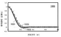
図9は、本開示の一部の実施態様により処理した音響信号の点広がり関数(PSF)のグラフ900である。曲線901は、回折限界音響画像のPSFを示す。曲線903は、フレーバー補間器840において線形補間を用いて得られた音響画像のPSFを示す。曲線902は、フレーバー補間器840における4点空間フィルタリングを用いて得られた音響画像のPSFを示す。グラフ900におけるPSFは、データのハニング重み付けおよび1つのフレーバーを用いて得られる。 FIG. 9 is a
図9に示す実施態様によれば、画像品質は、線形補間(曲線903)または4点フィルタリング(曲線902)を用いた主ローブ幅(分解能)で低下してもよい。また、4点FIRフィルターでのサイドローブレベルの顕著な増加も認めることができる。これは、単一フレーバーでの再構成エンジン530の大幅な簡略化からのトレードオフによるものである。 According to the embodiment shown in FIG. 9, the image quality may be reduced by the main lobe width (resolution) using linear interpolation (curve 903) or 4-point filtering (curve 902). A significant increase in sidelobe levels with the 4-point FIR filter can also be observed. This is a trade-off from the significant simplification of the
図10は、本開示のある実施態様により処理された音響信号についてのPSFのグラフ1000である。グラフ1000では、ハニング重り付けおよび2つのフレーバーを用いた画像再構成エンジン530についての結果が得られる。追加のフレーバーを再構成して、角度間隔が0.05ラジアンである要素間の画像に入れると、画像はよくサンプリングされ、補間または空間フィルタリングにより適切に真像を再構成することが観察される。曲線1003は、線形補間を用いた再構成エンジン530の結果を示す。曲線1002は、PSFについての4点空間フィルタリングを用いた再構成エンジン530の結果を示す。この場合、線形補間では、主ローブ幅が適度に増加し、一方、4点FIRフィルターでは、理論PSFと比較して、分解能がわずか5%低下する。いずれの補間法でもサイドローブの顕著な増加はない。 FIG. 10 is a
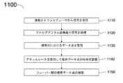
図11は、本開示のある実施態様による画像再構成についての方法1100のフローチャートである。方法1100は、場合によっては、FPGA250に設けられたメモリ回路およびプロセッサ回路によりおこなわれる。ある実施態様によれば、方法1100は、FPGA250により部分的におこなわれ、ADC回路216およびクロック/タイミング回路200により部分的におこなわれる。さらに、ある実施態様によれば、方法1100は、制御システム106によりおこなわれる。 FIG. 11 is a flowchart of
工程1110では、複数のトランスデューサから信号を受信することが含まれる。工程1110において、複数のトランスデューサは、合成開口を形成していてもよい。工程1110では、受信した信号は、トランスデューサの共鳴周波数Fcを中心とした周波数帯域を有するエコー信号でよい。工程1120では、中心周波数Fcの少なくとも2倍のデジタル化周波数を有するアナログ/デジタル変換器における信号をサンプリングすることが含まれる。工程1120は、中心周波数Fcの約4倍のデジタル化周波数を有する信号を処理することを含んでいてもよい。工程1130では、複素対数におけるデータ点を整理することが含まれる。ある実施態様によれば、工程1130は、データ点をインターリーブして、90°位相遅れだけ互いに分離した2セットとすることを含む。
工程1130では、受信した信号の位相は、2つのインターリーブデータセットにおける電圧値を測定することにより見いだすことができる。例えば、ある実施態様によれば、第1インターリーブデータセットの和を使用し、第2インターリーブデータセットの和を使用するとともに、全体のデータセットの位相を調整する。また、第1インターリーブデータセットの和を最大化する位相の値により、第2インターリーブデータセットの和を最小化してもよい。この値は、デジタル化周波数の値の約4分の1(1/4)の周波数で受信した音響エコー信号の位相でよい。ある実施態様によれば、複素対数は、上記した式1および式2で定義した複素数値c1およびc2である。 In
工程1140では、アキュムレータを用いて複素データ点の位相を調整することが含まれる。工程1140は、複素データ点と関連する焦点ゾーンを見いだすこと、およびデータ点の位相を見いだすこと(フレーバー方向との関連で)を含む。また、工程1140は、組織点と、合成開口における各トランスデューサ要素との間の位相値を用いて各データ点についての交差項を定義することを含む。工程1150では、フレーバー間の複素データ点を補間することが含まれる。ある実施態様によれば、工程1150は、別個に複素データ点の実部と虚部について、線形補間を用いることを含む。ある実施態様によれば、工程1150は、非線形関数を用いて複素データ点の強度値と位相値を補間することを含む(式3および式4参照)。また、工程1150は、補間値を用いて血管組織の2D画像を形成する工程を含んでいてもよい。
ある実施態様によれば、本明細書で開示されている4点FIR空間フィルターを用いた2フレーバー再構成エンジンを、8フレーバー再構成と比較して、認知できるような画像品質の低下がない画像再構成に使用する。方法4XDQS400と関連して少なくとも2倍の節減およびフレーバーにおいて4倍の減少(8から2に減少)を考慮すると、本明細書に開示されている構成により、複雑性が少なくとも8倍減少する。図3に関連して上記で詳細に説明した、コンパクトフォーカスメモリスキームにより、第1および第2差法を用いて合成開口におけるトランスデューサ要素についての位相情報を保存することで、複雑性がさらに減少する。 According to one embodiment, a two-flavor reconstruction engine using the four-point FIR spatial filter disclosed herein is compared to an eight-flavor reconstruction for an image with no perceptible degradation in image quality. Used for reconstruction. Considering at least 2-fold savings and a 4-fold reduction in flavor (reduced from 8 to 2) in connection with Method 4XDQS400, the configurations disclosed herein reduce complexity by at least 8-fold. The compact focus memory scheme described in detail above in connection with FIG. 3 further reduces complexity by storing phase information about the transducer elements in the synthetic aperture using the first and second difference methods. ..
デジタル化法4XDQS400により、PIM104の設計および操作が簡略となる。ある実施態様によれば、方法4XDQS400により、データ獲得についての速度要件が2倍減少できる。これとフレーバー再構成の簡略化により、全体の画像再構成プロセスにおいて最大8倍の向上ができる。ある実施態様によれば、PIM104は、PIM内に複雑度が低い(および低電力)再構成エンジンを備えたソリッドステートPIMであり、Aスキャンを低帯域幅デジタルリンクにより制御システム106に直接供給する。ある実施態様によれば、グレイスケールデータについてのPIM104と制御システム106との間の伝送速度は、8メガバイト/秒である。このような実施態様によれば、スキャン変換は、制御システム106でおこなわれ、一方、フレーバー補間はPIM104でおこなわれる。ある実施態様によれば、再構成ベースバンドデータは、PIM104と制御システム106との間の12メガバイト/秒リンクで送られ、フレーバー補間およびグレイスケール変換は制御システム106でおこなわれる。 The digitization method 4XDQS400 simplifies the design and operation of the
上記した開示の実施態様は、典型例にすぎない。当業者には、具体的に開示されているものから種々の代替実施態様が分かるであろう。また、これらの代替実施態様は、本開示の範囲内である。開示自体、以下の請求の範囲によってのみ限定される。 The above-described disclosure embodiment is only a typical example. Those skilled in the art will appreciate various alternative embodiments from those specifically disclosed. Also, these alternative embodiments are within the scope of the present disclosure. The disclosure itself is limited only by the following claims.
Claims (19)
Translated fromJapanese患者インターフェースモジュール(PIM)であって、
パルス送信器回路と、
アナログ/デジタル変換回路と、
再構成FPGA回路と、
を備えているPIMと、
遠位端付近に検出ヘッドを有するカテーテルであって、前記検出ヘッドは、開口構成に関連付けられたトランスデューサ要素のアレイであって、画像データを得るように構成されているトランスデューサ要素のアレイを備え、前記PIMは、前記トランスデューサ要素のアレイにより得られた前記画像データを処理するように構成されている、カテーテルと、
前記PIMとは別個の制御システムであって、前記制御システムは、前記PIMから、処理された前記画像データを受信し、処理された前記画像データをディスプレイに出力するように構成されている、制御システムと、
を備え、
前記PIMは、前記制御システムと前記カテーテルとの間に通信可能に配置され、
前記再構成FPGA回路は、
前記アナログ/デジタル変換回路によってエコー信号から変換された、デジタル化点を含むデジタルデータを受け、該デジタルデータを複素ベースバンドに変換する内部調整回路と、
前記複素ベースバンドを形成する複素数値をバッファリングするバッファ回路と、
前記バッファ回路によってバッファリングされた前記複素数値を含む信号を処理する再構成エンジン回路と、
を備え、
前記再構成エンジン回路は、
前記信号の位相を測定するための回路と、
フレーバー補間回路と、
を備え、
前記信号の前記位相を測定するための前記回路は、前記信号の中心周波数の各サイクルについての2つの複素数を形成するデジタル化点を含み、
前記パルス送信器回路は、前記開口構成のフレーバーに基づいて、前記トランスデューサ要素のアレイに対するトリガーを生成するように構成され、
前記フレーバー補間回路は、前記開口構成の前記フレーバーに基づいて、前記信号に対して補間をおこなうように構成されている、システム。A system for collecting tissue images
Patient Interface Module (PIM)
With the pulse transmitter circuit,
Analog / digital conversion circuit and
Reconstructed FPGA circuit and
With PIM and
A catheter having a detection head near the distal end, said detection head comprising an array of transducer elements associated with an aperture configuration, the transducer elements configured to obtain image data. The PIM is configured to process the image data obtained by the array of transducer elements, the catheter and the catheter.
A control system that is separate from the PIM, the control system is configured to receive the processed image data from the PIM and output the processed image data to a display. With the system
With
The PIM is communicably disposed between the control system and the catheter.
The reconstructed FPGA circuit
An internal adjustment circuit that receives digital data including a digitization point converted from an echo signal by the analog / digital conversion circuit and converts the digital data into a complex base band.
A buffer circuit that buffers complex values that form the complex baseband,
A reconstruction engine circuit that processes a signal containing the complex value buffered by the buffer circuit, and
With
The reconstructed engine circuit
A circuit for measuring the phase of the signal and
Flavor interpolation circuit and
With
The circuit for measuring the phase of the signal includes digitization points forming two complex numbers for each cycle of the center frequency of the signal.
The pulse transmitter circuit is configured to generate a trigger for the array of transducer elements based on the flavor of the aperture configuration.
The flavor interpolation circuit is a system configured to interpolate the signal based on the flavor having the aperture configuration.
遅延回路と、
平均化回路と、
前記遅延回路の信号から、前記平均化回路からの信号を減算するためのオフセット減算回路と、
前記オフセット減算回路のサンプルから複素数を与えるためのI/Q変換回路と、
前記I/Q変換回路からの複素数値を補間するための補間回路と、
をさらに備えている、請求項1に記載のシステム。The internal adjustment circuit
With a delay circuit
With the averaging circuit,
An offset subtraction circuit for subtracting a signal from the averaging circuit from the signal of the delay circuit,
An I / Q conversion circuit for giving a complex number from the sample of the offset subtraction circuit, and
An interpolation circuit for interpolating complex values from the I / Q conversion circuit and
The system according to claim 1, further comprising.
前記信号の前記位相を測定するための前記回路は、前記超音波エコーに対応する前記電気信号の位相を測定するように構成されている、請求項1に記載のシステム。The array of transducer elements is configured to convert ultrasonic echoes received from tissue into corresponding electrical signals.
The system of claim 1, wherein the circuit for measuring the phase of the signal is configured to measure the phase of the electrical signal corresponding to the ultrasonic echo.
前記パルス送信器回路および前記アナログ/デジタル変換回路に接続され、送信タイミング信号を前記パルス送信器回路に出力し、デジタル化信号を前記アナログ/デジタル変換回路に出力するタイミング回路
をさらに備えている、請求項1に記載のシステム。The PIM is
A timing circuit that is connected to the pulse transmitter circuit and the analog / digital conversion circuit, outputs a transmission timing signal to the pulse transmitter circuit, and outputs a digitized signal to the analog / digital conversion circuit is further provided. The system according to claim 1.
遠位端付近に検出ヘッドを有するカテーテルであって、前記検出ヘッドは、開口構成に関連付けられたトランスデューサ要素のアレイであって、画像データを得るように構成されているトランスデューサ要素のアレイを備えている、カテーテルと、
前記トランスデューサ要素のアレイにより得られた前記画像データを処理するように構成されている患者インターフェースモジュール(PIM)であって、
前記開口構成のフレーバーに基づいて、前記トランスデューサ要素のアレイに対するトリガーを生成するように構成されているパルス送信器回路と、
アナログ/デジタル変換回路と、
前記開口構成の前記フレーバーに基づいて、前記カテーテルによって受信されたエコー信号から前記アナログ/デジタル変換回路によって変換されたデジタルデータにおいて、フレーバー間のデータ値を補間して追加のフレーバー位置での値を得る補間をおこなうように構成されている再構成FPGA回路と、
を備えているPIMと、
前記PIMとは別個の制御システムであって、前記PIMは、前記制御システムと前記カテーテルとの間に通信可能に配置され、前記制御システムは、前記PIMから、処理された前記画像データを受信し、処理された前記画像データをディスプレイに出力するように構成されている、制御システムと、
を備えているシステム。A system for collecting tissue images
A catheter having a detection head near the distal end, said detection head comprising an array of transducer elements associated with an aperture configuration, the transducer elements configured to obtain image data. There is a catheter and
A patient interface module (PIM) configured to process the image data obtained by the array of transducer elements.
A pulse transmitter circuit configured to generate a trigger for the array of transducer elements based on the flavor of the aperture configuration.
Analog / digital conversion circuit and
In the digital data converted by the analog /digital conversion circuit from the echo signal received by the catheter based on the flavor of the opening configuration, the data value between the flavors is interpolated to obtain the value at the additional flavor position. A reconfigured FPGA circuit configured to perform the interpolation to obtain
With PIM and
A control system separate from the PIM, the PIM is communicably arranged between the control system and the catheter, which receives the processed image data from the PIM. A control system configured to output the processed image data to a display.
A system that features.
Applications Claiming Priority (2)
| Application Number | Priority Date | Filing Date | Title |
|---|---|---|---|
| US201261746733P | 2012-12-28 | 2012-12-28 | |
| US61/746,733 | 2012-12-28 |
Related Parent Applications (1)
| Application Number | Title | Priority Date | Filing Date |
|---|---|---|---|
| JP2015550700ADivisionJP6383731B2 (en) | 2012-12-28 | 2013-12-20 | Synthetic aperture image reconstruction system in patient interface module (PIM) |
Publications (2)
| Publication Number | Publication Date |
|---|---|
| JP2018126667A JP2018126667A (en) | 2018-08-16 |
| JP6831349B2true JP6831349B2 (en) | 2021-02-17 |
Family
ID=51017961
Family Applications (2)
| Application Number | Title | Priority Date | Filing Date |
|---|---|---|---|
| JP2015550700AActiveJP6383731B2 (en) | 2012-12-28 | 2013-12-20 | Synthetic aperture image reconstruction system in patient interface module (PIM) |
| JP2018102529AExpired - Fee RelatedJP6831349B2 (en) | 2012-12-28 | 2018-05-29 | Synthetic Aperture Image Reconstruction System in Patient Interface Module (PIM) |
Family Applications Before (1)
| Application Number | Title | Priority Date | Filing Date |
|---|---|---|---|
| JP2015550700AActiveJP6383731B2 (en) | 2012-12-28 | 2013-12-20 | Synthetic aperture image reconstruction system in patient interface module (PIM) |
Country Status (5)
| Country | Link |
|---|---|
| US (2) | US10420531B2 (en) |
| EP (1) | EP2938268B1 (en) |
| JP (2) | JP6383731B2 (en) |
| CA (1) | CA2896513A1 (en) |
| WO (1) | WO2014105717A1 (en) |
Families Citing this family (22)
| Publication number | Priority date | Publication date | Assignee | Title |
|---|---|---|---|---|
| US10231701B2 (en) | 2013-03-15 | 2019-03-19 | Provisio Medical, Inc. | Distance, diameter and area determining device |
| US10716536B2 (en)* | 2013-07-17 | 2020-07-21 | Tissue Differentiation Intelligence, Llc | Identifying anatomical structures |
| US10780298B2 (en) | 2013-08-22 | 2020-09-22 | The Regents Of The University Of Michigan | Histotripsy using very short monopolar ultrasound pulses |
| EP4218600A1 (en)* | 2014-09-11 | 2023-08-02 | Provisio Medical, Inc. | Distance, diameter and area measuring device |
| GB2539368A (en) | 2015-02-09 | 2016-12-21 | Univ Erasmus Med Ct Rotterdam | Intravascular photoacoustic imaging |
| KR20160097862A (en)* | 2015-02-10 | 2016-08-18 | 삼성전자주식회사 | Portable ultrasound apparatus, and control method for same |
| JP6979882B2 (en) | 2015-06-24 | 2021-12-15 | ザ リージェンツ オブ ザ ユニヴァシティ オブ ミシガン | Tissue disruption therapy systems and methods for the treatment of brain tissue |
| US11986341B1 (en) | 2016-05-26 | 2024-05-21 | Tissue Differentiation Intelligence, Llc | Methods for accessing spinal column using B-mode imaging to determine a trajectory without penetrating the the patient's anatomy |
| JP6747108B2 (en)* | 2016-07-05 | 2020-08-26 | コニカミノルタ株式会社 | Ultrasonic signal processing device, ultrasonic signal processing method, and ultrasonic diagnostic device |
| EP3697314B1 (en) | 2017-10-19 | 2021-04-21 | Koninklijke Philips N.V. | Wireless digital patient interface module using wireless charging |
| US20210196242A1 (en)* | 2017-10-19 | 2021-07-01 | Koninklijke Philips N.V. | Digital rotational patient interface module |
| WO2019077141A1 (en)* | 2017-10-20 | 2019-04-25 | Koninklijke Philips N.V. | Intraluminal medical system with multi-device connectors |
| WO2019174984A1 (en)* | 2018-03-15 | 2019-09-19 | Koninklijke Philips N.V. | Variable intraluminal ultrasound transmit pulse generation and control devices, systems, and methods |
| US11547303B2 (en)* | 2018-05-04 | 2023-01-10 | Hi Llc | Non-invasive optical detection system and method of multiple-scattered light with swept source illumination |
| AU2019389001B2 (en) | 2018-11-28 | 2025-08-14 | Histosonics, Inc. | Histotripsy systems and methods |
| CN109782661B (en)* | 2019-01-04 | 2020-10-16 | 中国科学院声学研究所东海研究站 | System and method for realizing reconfigurable and multi-output real-time processing based on FPGA |
| US11813485B2 (en) | 2020-01-28 | 2023-11-14 | The Regents Of The University Of Michigan | Systems and methods for histotripsy immunosensitization |
| JP2023540482A (en) | 2020-08-27 | 2023-09-25 | ザ リージェンツ オブ ザ ユニバーシティー オブ ミシガン | Ultrasonic transducer with transmitting and receiving functions for histotripsy |
| US11686072B2 (en) | 2020-11-18 | 2023-06-27 | Caterpillar Inc. | Work implement assembly using adapters, adapter covers, and a notched base edge |
| US11939740B2 (en) | 2020-11-18 | 2024-03-26 | Caterpillar Inc. | Work implement assembly using adapters, adapter covers, and a notched base edge |
| US11808017B2 (en) | 2020-11-18 | 2023-11-07 | Caterpillar Inc. | Work implement assembly using adapters, adapter covers, and a notched base edge |
| EP4608504A1 (en) | 2022-10-28 | 2025-09-03 | Histosonics, Inc. | Histotripsy systems and methods |
Family Cites Families (37)
| Publication number | Priority date | Publication date | Assignee | Title |
|---|---|---|---|---|
| US4683893A (en)* | 1986-06-30 | 1987-08-04 | North American Philips Corporation | Amplitude conditional signal processing for ultrasound frequency estimation |
| CA1334966C (en) | 1987-03-23 | 1995-03-28 | Dow Corning Corporation | Siloxane-polyalphaolefin hydraulic fluid |
| US4917097A (en)* | 1987-10-27 | 1990-04-17 | Endosonics Corporation | Apparatus and method for imaging small cavities |
| JPH0563509U (en)* | 1992-02-07 | 1993-08-24 | 横河メディカルシステム株式会社 | Receiving digital beam former |
| US5793701A (en)* | 1995-04-07 | 1998-08-11 | Acuson Corporation | Method and apparatus for coherent image formation |
| US5771895A (en) | 1996-02-12 | 1998-06-30 | Slager; Cornelis J. | Catheter for obtaining three-dimensional reconstruction of a vascular lumen and wall |
| US6241675B1 (en)* | 1998-06-09 | 2001-06-05 | Volumetrics Medical Imaging | Methods and systems for determining velocity of tissue using three dimensional ultrasound data |
| GB2345543A (en) | 1999-01-06 | 2000-07-12 | Intravascular Res Ltd | Ultrasonic visualisation system with remote components |
| US20020115931A1 (en) | 2001-02-21 | 2002-08-22 | Strauss H. William | Localizing intravascular lesions on anatomic images |
| US6592520B1 (en)* | 2001-07-31 | 2003-07-15 | Koninklijke Philips Electronics N.V. | Intravascular ultrasound imaging apparatus and method |
| CA2513422C (en) | 2003-01-15 | 2013-12-24 | University Of Virginia Patent Foundation | System and method for ultrasound c-scanning |
| US20050203402A1 (en)* | 2004-02-09 | 2005-09-15 | Angelsen Bjorn A. | Digital ultrasound beam former with flexible channel and frequency range reconfiguration |
| US7699782B2 (en)* | 2004-03-09 | 2010-04-20 | Angelsen Bjoern A J | Extended, ultrasound real time 3D image probe for insertion into the body |
| US20050203416A1 (en)* | 2004-03-10 | 2005-09-15 | Angelsen Bjorn A. | Extended, ultrasound real time 2D imaging probe for insertion into the body |
| US7207943B2 (en)* | 2004-03-24 | 2007-04-24 | Siemens Medical Solutions Usa, Inc. | Synthetic elevation aperture for ultrasound systems and methods |
| US7744538B2 (en) | 2004-11-01 | 2010-06-29 | Siemens Medical Solutions Usa, Inc. | Minimum arc velocity interpolation for three-dimensional ultrasound imaging |
| US7930014B2 (en) | 2005-01-11 | 2011-04-19 | Volcano Corporation | Vascular image co-registration |
| CA2603495A1 (en) | 2005-04-01 | 2006-10-12 | Visualsonics Inc. | System and method for 3-d visualization of vascular structures using ultrasound |
| US20070043596A1 (en)* | 2005-08-16 | 2007-02-22 | General Electric Company | Physiology network and workstation for use therewith |
| WO2007035765A2 (en)* | 2005-09-19 | 2007-03-29 | University Of Virginia Patent Foundation | System and method for adaptive beamforming for image reconstruction and/or target/source localization |
| EP1952175B1 (en)* | 2005-11-02 | 2013-01-09 | Visualsonics, Inc. | Digital transmit beamformer for an arrayed ultrasound transducer system |
| RU2465826C2 (en) | 2006-12-15 | 2012-11-10 | Конинклейке Филипс Электроникс Н.В. | X-ray imager with spectral resolution |
| JP5016326B2 (en)* | 2007-03-06 | 2012-09-05 | 株式会社日立メディコ | Ultrasonic diagnostic equipment |
| US9629571B2 (en) | 2007-03-08 | 2017-04-25 | Sync-Rx, Ltd. | Co-use of endoluminal data and extraluminal imaging |
| CN101373181B (en)* | 2007-08-24 | 2012-03-21 | 深圳迈瑞生物医疗电子股份有限公司 | Method and apparatus for calculating point-to-point trace-changing coefficient in real time |
| EP2257328A2 (en)* | 2008-03-27 | 2010-12-08 | Nellcor Puritan Bennett LLC | Breathing assistance systems with lung recruitment maneuvers |
| JP5063509B2 (en) | 2008-06-30 | 2012-10-31 | 三菱電機株式会社 | Air conditioner |
| TWI379105B (en) | 2008-07-17 | 2012-12-11 | Coretronic Corp | Optical film and backlight module using the same |
| GB0905377D0 (en)* | 2009-03-30 | 2009-05-13 | Danmedical Ltd | Medical apparatus |
| JP5398613B2 (en)* | 2009-04-14 | 2014-01-29 | 富士フイルム株式会社 | Ultrasonic diagnostic equipment |
| US8398552B2 (en) | 2009-04-14 | 2013-03-19 | Fujifilm Corporation | Ultrasonic diagnostic apparatus |
| JP5390942B2 (en) | 2009-06-03 | 2014-01-15 | 富士フイルム株式会社 | Ultrasonic diagnostic apparatus and signal processing program |
| CN102665569B (en) | 2009-10-12 | 2015-05-13 | 硅谷医疗器械有限公司 | Intravascular ultrasound system for co-registered imaging |
| EP2578163A1 (en)* | 2010-06-07 | 2013-04-10 | Panasonic Corporation | Malignant tissue tumor detection method and malignant tissue tumor detection device |
| CN107669295B (en)* | 2010-09-10 | 2021-04-20 | 阿西斯特医疗系统有限公司 | Apparatus and method for medical image search |
| JP6440359B2 (en)* | 2011-01-31 | 2018-12-19 | サニーブルック ヘルス サイエンシーズ センター | Ultrasonic probe with an ultrasonic transducer that can be processed on a common electrical channel |
| US9433398B2 (en)* | 2011-06-08 | 2016-09-06 | University Of Virginia Patent Foundation | Separable beamforming for ultrasound array |
- 2013
- 2013-12-20WOPCT/US2013/077009patent/WO2014105717A1/enactiveApplication Filing
- 2013-12-20JPJP2015550700Apatent/JP6383731B2/enactiveActive
- 2013-12-20EPEP13868858.5Apatent/EP2938268B1/enactiveActive
- 2013-12-20CACA2896513Apatent/CA2896513A1/ennot_activeAbandoned
- 2013-12-20USUS14/137,304patent/US10420531B2/enactiveActive
- 2018
- 2018-05-29JPJP2018102529Apatent/JP6831349B2/ennot_activeExpired - Fee Related
- 2019
- 2019-09-24USUS16/580,991patent/US12144677B2/enactiveActive
Also Published As
| Publication number | Publication date |
|---|---|
| EP2938268A1 (en) | 2015-11-04 |
| JP2018126667A (en) | 2018-08-16 |
| JP6383731B2 (en) | 2018-08-29 |
| US20200015779A1 (en) | 2020-01-16 |
| US12144677B2 (en) | 2024-11-19 |
| US10420531B2 (en) | 2019-09-24 |
| EP2938268B1 (en) | 2022-11-30 |
| WO2014105717A1 (en) | 2014-07-03 |
| US20140187925A1 (en) | 2014-07-03 |
| JP2016501677A (en) | 2016-01-21 |
| CA2896513A1 (en) | 2014-07-03 |
| EP2938268A4 (en) | 2016-08-24 |
Similar Documents
| Publication | Publication Date | Title |
|---|---|---|
| JP6831349B2 (en) | Synthetic Aperture Image Reconstruction System in Patient Interface Module (PIM) | |
| US11559277B2 (en) | Ultrasound 3D imaging system | |
| US11103221B2 (en) | System and method for providing variable ultrasound array processing in a post-storage mode | |
| US11596389B2 (en) | Method for multi-frequency imaging and composite image display using high-bandwidth transducer outputs | |
| US10426435B2 (en) | Ultrasound 3D imaging system | |
| US7402136B2 (en) | Efficient ultrasound system for two-dimensional C-scan imaging and related method thereof | |
| KR101242368B1 (en) | Mobile ultrasound diagnosis probe apparatus for using two-dimension array data, mobile ultrasound diagnosis system using the same | |
| US20140046188A1 (en) | System and Method for Ultrasonic Diagnostics | |
| US20150025387A1 (en) | Efficient architecture for 3d and planar ultrasonic imaging-synthetic axial acquisition and method thereof | |
| EP3893022A1 (en) | Ultrasound imaging system memory architecture | |
| CN102469985B (en) | Diagnostic ultrasound equipment | |
| EP2934333B1 (en) | Method for multi-frequency imaging using high-bandwidth transducer outputs | |
| Whittingham | New and future developments in ultrasonic imaging | |
| CA2882873A1 (en) | System and method for focusing ultrasound image data | |
| US20250169792A1 (en) | Ultrasound 3d imaging system | |
| HK40063952A (en) | Ultrasound imaging system memory architecture |
Legal Events
| Date | Code | Title | Description |
|---|---|---|---|
| A621 | Written request for application examination | Free format text:JAPANESE INTERMEDIATE CODE: A621 Effective date:20180529 | |
| A131 | Notification of reasons for refusal | Free format text:JAPANESE INTERMEDIATE CODE: A131 Effective date:20190305 | |
| A977 | Report on retrieval | Free format text:JAPANESE INTERMEDIATE CODE: A971007 Effective date:20190228 | |
| A601 | Written request for extension of time | Free format text:JAPANESE INTERMEDIATE CODE: A601 Effective date:20190524 | |
| A131 | Notification of reasons for refusal | Free format text:JAPANESE INTERMEDIATE CODE: A131 Effective date:20191203 | |
| A601 | Written request for extension of time | Free format text:JAPANESE INTERMEDIATE CODE: A601 Effective date:20200218 | |
| A521 | Request for written amendment filed | Free format text:JAPANESE INTERMEDIATE CODE: A523 Effective date:20200603 | |
| A131 | Notification of reasons for refusal | Free format text:JAPANESE INTERMEDIATE CODE: A131 Effective date:20200929 | |
| A521 | Request for written amendment filed | Free format text:JAPANESE INTERMEDIATE CODE: A523 Effective date:20201210 | |
| TRDD | Decision of grant or rejection written | ||
| A01 | Written decision to grant a patent or to grant a registration (utility model) | Free format text:JAPANESE INTERMEDIATE CODE: A01 Effective date:20210105 | |
| A61 | First payment of annual fees (during grant procedure) | Free format text:JAPANESE INTERMEDIATE CODE: A61 Effective date:20210128 | |
| R150 | Certificate of patent or registration of utility model | Ref document number:6831349 Country of ref document:JP Free format text:JAPANESE INTERMEDIATE CODE: R150 | |
| S531 | Written request for registration of change of domicile | Free format text:JAPANESE INTERMEDIATE CODE: R313531 | |
| S533 | Written request for registration of change of name | Free format text:JAPANESE INTERMEDIATE CODE: R313533 | |
| R350 | Written notification of registration of transfer | Free format text:JAPANESE INTERMEDIATE CODE: R350 | |
| LAPS | Cancellation because of no payment of annual fees |