JP6831210B2 - Vacuum cleaner - Google Patents
Vacuum cleanerDownload PDFInfo
- Publication number
- JP6831210B2 JP6831210B2JP2016215460AJP2016215460AJP6831210B2JP 6831210 B2JP6831210 B2JP 6831210B2JP 2016215460 AJP2016215460 AJP 2016215460AJP 2016215460 AJP2016215460 AJP 2016215460AJP 6831210 B2JP6831210 B2JP 6831210B2
- Authority
- JP
- Japan
- Prior art keywords
- vacuum cleaner
- main body
- body case
- map
- data
- Prior art date
- Legal status (The legal status is an assumption and is not a legal conclusion. Google has not performed a legal analysis and makes no representation as to the accuracy of the status listed.)
- Active
Links
- 238000013507mappingMethods0.000claimsdescription55
- 238000004364calculation methodMethods0.000claimsdescription31
- 238000003384imaging methodMethods0.000claimsdescription21
- 238000004891communicationMethods0.000claimsdescription18
- 238000004140cleaningMethods0.000description74
- 238000012545processingMethods0.000description32
- 239000000428dustSubstances0.000description14
- 238000000034methodMethods0.000description8
- 238000003702image correctionMethods0.000description7
- 238000005286illuminationMethods0.000description5
- 230000005540biological transmissionEffects0.000description4
- 230000006870functionEffects0.000description4
- 238000013500data storageMethods0.000description2
- 238000010586diagramMethods0.000description2
- 238000003708edge detectionMethods0.000description2
- 230000003287optical effectEffects0.000description2
- 238000012937correctionMethods0.000description1
- 238000001514detection methodMethods0.000description1
- 238000005516engineering processMethods0.000description1
- 239000000284extractSubstances0.000description1
- 230000004807localizationEffects0.000description1
- 238000012986modificationMethods0.000description1
- 230000004048modificationEffects0.000description1
- 230000004044responseEffects0.000description1
- 238000010079rubber tappingMethods0.000description1
- 229920003002synthetic resinPolymers0.000description1
- 239000000057synthetic resinSubstances0.000description1
- 230000007704transitionEffects0.000description1
Images


Classifications
- G—PHYSICS
- G05—CONTROLLING; REGULATING
- G05D—SYSTEMS FOR CONTROLLING OR REGULATING NON-ELECTRIC VARIABLES
- G05D1/00—Control of position, course, altitude or attitude of land, water, air or space vehicles, e.g. using automatic pilots
- G05D1/02—Control of position or course in two dimensions
- G05D1/021—Control of position or course in two dimensions specially adapted to land vehicles
- G05D1/0268—Control of position or course in two dimensions specially adapted to land vehicles using internal positioning means
- G05D1/0274—Control of position or course in two dimensions specially adapted to land vehicles using internal positioning means using mapping information stored in a memory device
- G—PHYSICS
- G05—CONTROLLING; REGULATING
- G05D—SYSTEMS FOR CONTROLLING OR REGULATING NON-ELECTRIC VARIABLES
- G05D1/00—Control of position, course, altitude or attitude of land, water, air or space vehicles, e.g. using automatic pilots
- G05D1/0088—Control of position, course, altitude or attitude of land, water, air or space vehicles, e.g. using automatic pilots characterized by the autonomous decision making process, e.g. artificial intelligence, predefined behaviours
- A—HUMAN NECESSITIES
- A47—FURNITURE; DOMESTIC ARTICLES OR APPLIANCES; COFFEE MILLS; SPICE MILLS; SUCTION CLEANERS IN GENERAL
- A47L—DOMESTIC WASHING OR CLEANING; SUCTION CLEANERS IN GENERAL
- A47L9/00—Details or accessories of suction cleaners, e.g. mechanical means for controlling the suction or for effecting pulsating action; Storing devices specially adapted to suction cleaners or parts thereof; Carrying-vehicles specially adapted for suction cleaners
- A47L9/28—Installation of the electric equipment, e.g. adaptation or attachment to the suction cleaner; Controlling suction cleaners by electric means
- A—HUMAN NECESSITIES
- A47—FURNITURE; DOMESTIC ARTICLES OR APPLIANCES; COFFEE MILLS; SPICE MILLS; SUCTION CLEANERS IN GENERAL
- A47L—DOMESTIC WASHING OR CLEANING; SUCTION CLEANERS IN GENERAL
- A47L11/00—Machines for cleaning floors, carpets, furniture, walls, or wall coverings
- A47L11/40—Parts or details of machines not provided for in groups A47L11/02 - A47L11/38, or not restricted to one of these groups, e.g. handles, arrangements of switches, skirts, buffers, levers
- A47L11/4011—Regulation of the cleaning machine by electric means; Control systems and remote control systems therefor
- A—HUMAN NECESSITIES
- A47—FURNITURE; DOMESTIC ARTICLES OR APPLIANCES; COFFEE MILLS; SPICE MILLS; SUCTION CLEANERS IN GENERAL
- A47L—DOMESTIC WASHING OR CLEANING; SUCTION CLEANERS IN GENERAL
- A47L11/00—Machines for cleaning floors, carpets, furniture, walls, or wall coverings
- A47L11/40—Parts or details of machines not provided for in groups A47L11/02 - A47L11/38, or not restricted to one of these groups, e.g. handles, arrangements of switches, skirts, buffers, levers
- A47L11/4061—Steering means; Means for avoiding obstacles; Details related to the place where the driver is accommodated
- A—HUMAN NECESSITIES
- A47—FURNITURE; DOMESTIC ARTICLES OR APPLIANCES; COFFEE MILLS; SPICE MILLS; SUCTION CLEANERS IN GENERAL
- A47L—DOMESTIC WASHING OR CLEANING; SUCTION CLEANERS IN GENERAL
- A47L11/00—Machines for cleaning floors, carpets, furniture, walls, or wall coverings
- A47L11/40—Parts or details of machines not provided for in groups A47L11/02 - A47L11/38, or not restricted to one of these groups, e.g. handles, arrangements of switches, skirts, buffers, levers
- A47L11/4063—Driving means; Transmission means therefor
- A47L11/4066—Propulsion of the whole machine
- A—HUMAN NECESSITIES
- A47—FURNITURE; DOMESTIC ARTICLES OR APPLIANCES; COFFEE MILLS; SPICE MILLS; SUCTION CLEANERS IN GENERAL
- A47L—DOMESTIC WASHING OR CLEANING; SUCTION CLEANERS IN GENERAL
- A47L9/00—Details or accessories of suction cleaners, e.g. mechanical means for controlling the suction or for effecting pulsating action; Storing devices specially adapted to suction cleaners or parts thereof; Carrying-vehicles specially adapted for suction cleaners
- A47L9/28—Installation of the electric equipment, e.g. adaptation or attachment to the suction cleaner; Controlling suction cleaners by electric means
- A47L9/2805—Parameters or conditions being sensed
- A47L9/2826—Parameters or conditions being sensed the condition of the floor
- A—HUMAN NECESSITIES
- A47—FURNITURE; DOMESTIC ARTICLES OR APPLIANCES; COFFEE MILLS; SPICE MILLS; SUCTION CLEANERS IN GENERAL
- A47L—DOMESTIC WASHING OR CLEANING; SUCTION CLEANERS IN GENERAL
- A47L9/00—Details or accessories of suction cleaners, e.g. mechanical means for controlling the suction or for effecting pulsating action; Storing devices specially adapted to suction cleaners or parts thereof; Carrying-vehicles specially adapted for suction cleaners
- A47L9/28—Installation of the electric equipment, e.g. adaptation or attachment to the suction cleaner; Controlling suction cleaners by electric means
- A47L9/2836—Installation of the electric equipment, e.g. adaptation or attachment to the suction cleaner; Controlling suction cleaners by electric means characterised by the parts which are controlled
- A47L9/2852—Elements for displacement of the vacuum cleaner or the accessories therefor, e.g. wheels, casters or nozzles
- A—HUMAN NECESSITIES
- A47—FURNITURE; DOMESTIC ARTICLES OR APPLIANCES; COFFEE MILLS; SPICE MILLS; SUCTION CLEANERS IN GENERAL
- A47L—DOMESTIC WASHING OR CLEANING; SUCTION CLEANERS IN GENERAL
- A47L9/00—Details or accessories of suction cleaners, e.g. mechanical means for controlling the suction or for effecting pulsating action; Storing devices specially adapted to suction cleaners or parts thereof; Carrying-vehicles specially adapted for suction cleaners
- A47L9/28—Installation of the electric equipment, e.g. adaptation or attachment to the suction cleaner; Controlling suction cleaners by electric means
- A47L9/2894—Details related to signal transmission in suction cleaners
- G—PHYSICS
- G05—CONTROLLING; REGULATING
- G05D—SYSTEMS FOR CONTROLLING OR REGULATING NON-ELECTRIC VARIABLES
- G05D1/00—Control of position, course, altitude or attitude of land, water, air or space vehicles, e.g. using automatic pilots
- G05D1/02—Control of position or course in two dimensions
- G—PHYSICS
- G05—CONTROLLING; REGULATING
- G05D—SYSTEMS FOR CONTROLLING OR REGULATING NON-ELECTRIC VARIABLES
- G05D1/00—Control of position, course, altitude or attitude of land, water, air or space vehicles, e.g. using automatic pilots
- G05D1/02—Control of position or course in two dimensions
- G05D1/021—Control of position or course in two dimensions specially adapted to land vehicles
- G05D1/0231—Control of position or course in two dimensions specially adapted to land vehicles using optical position detecting means
- G05D1/0246—Control of position or course in two dimensions specially adapted to land vehicles using optical position detecting means using a video camera in combination with image processing means
- G05D1/0251—Control of position or course in two dimensions specially adapted to land vehicles using optical position detecting means using a video camera in combination with image processing means extracting 3D information from a plurality of images taken from different locations, e.g. stereo vision
- G—PHYSICS
- G05—CONTROLLING; REGULATING
- G05D—SYSTEMS FOR CONTROLLING OR REGULATING NON-ELECTRIC VARIABLES
- G05D1/00—Control of position, course, altitude or attitude of land, water, air or space vehicles, e.g. using automatic pilots
- G05D1/02—Control of position or course in two dimensions
- G05D1/021—Control of position or course in two dimensions specially adapted to land vehicles
- G05D1/0276—Control of position or course in two dimensions specially adapted to land vehicles using signals provided by a source external to the vehicle
- A—HUMAN NECESSITIES
- A47—FURNITURE; DOMESTIC ARTICLES OR APPLIANCES; COFFEE MILLS; SPICE MILLS; SUCTION CLEANERS IN GENERAL
- A47L—DOMESTIC WASHING OR CLEANING; SUCTION CLEANERS IN GENERAL
- A47L2201/00—Robotic cleaning machines, i.e. with automatic control of the travelling movement or the cleaning operation
- A47L2201/02—Docking stations; Docking operations
- A—HUMAN NECESSITIES
- A47—FURNITURE; DOMESTIC ARTICLES OR APPLIANCES; COFFEE MILLS; SPICE MILLS; SUCTION CLEANERS IN GENERAL
- A47L—DOMESTIC WASHING OR CLEANING; SUCTION CLEANERS IN GENERAL
- A47L2201/00—Robotic cleaning machines, i.e. with automatic control of the travelling movement or the cleaning operation
- A47L2201/04—Automatic control of the travelling movement; Automatic obstacle detection
Landscapes
- Engineering & Computer Science (AREA)
- Radar, Positioning & Navigation (AREA)
- Physics & Mathematics (AREA)
- Aviation & Aerospace Engineering (AREA)
- Remote Sensing (AREA)
- General Physics & Mathematics (AREA)
- Automation & Control Theory (AREA)
- Mechanical Engineering (AREA)
- Electromagnetism (AREA)
- Computer Vision & Pattern Recognition (AREA)
- Business, Economics & Management (AREA)
- Evolutionary Computation (AREA)
- Game Theory and Decision Science (AREA)
- Medical Informatics (AREA)
- Artificial Intelligence (AREA)
- Health & Medical Sciences (AREA)
- Multimedia (AREA)
- Control Of Position, Course, Altitude, Or Attitude Of Moving Bodies (AREA)
- Electric Vacuum Cleaner (AREA)
Description
Translated fromJapanese本発明の実施形態は、本体ケースに配置された撮像手段を備えた電気掃除機に関する。 An embodiment of the present invention relates to a vacuum cleaner provided with an imaging means arranged in a main body case.
従来、被掃除面としての床面上を自律走行しながら床面を掃除する、いわゆる自律走行型の電気掃除機(掃除ロボット)が知られている。 Conventionally, a so-called autonomous traveling type electric vacuum cleaner (cleaning robot) that cleans the floor surface while autonomously traveling on the floor surface as a surface to be cleaned is known.
このような電気掃除機において、効率のよい掃除を実現するために、掃除したい部屋の大きさや形状、および障害物などを地図に反映して作成(マッピング)し、この作成した地図に基づいて最適な走行経路を設定して、その走行経路に沿って走行する技術がある。この地図は、例えば本体ケースの上部に配置したカメラを用いて撮像した天井の画像などに基づいて作成される。 In such an electric vacuum cleaner, in order to realize efficient cleaning, the size and shape of the room to be cleaned, obstacles, etc. are reflected on the map and created (mapped), and it is optimal based on this created map. There is a technology to set a different travel route and travel along the travel route. This map is created based on, for example, an image of the ceiling taken by a camera placed on the upper part of the main body case.
このように地図を作成する場合、例えば本体ケースが入り込めるベッドの下部やテーブルの下部などに移動したときに、カメラはベッドやテーブルの裏面側などを撮像するに過ぎず、天井を撮像できないことから、作成される地図の精度が低下する。そして、地図の作成精度が低下すると、このマップに基づいて設定される電気掃除機の走行経路も精度が低下し、掃除の効率が低下する。 When creating a map in this way, for example, when moving to the lower part of the bed or the lower part of the table where the main body case can be inserted, the camera only images the back side of the bed or table, and cannot image the ceiling. , The accuracy of the created map is reduced. Then, when the accuracy of creating the map is lowered, the accuracy of the traveling route of the vacuum cleaner set based on this map is also lowered, and the cleaning efficiency is lowered.
本発明が解決しようとする課題は、地図の作成精度を向上して効率よく掃除できる電気掃除機を提供することである。 An object to be solved by the present invention is to provide an electric vacuum cleaner capable of efficiently cleaning by improving the accuracy of creating a map.
実施形態の電気掃除機は、本体ケースと、駆動部と、撮像手段と、距離算出手段と、自己位置推定手段と、マッピング手段と、制御手段とを有する。駆動部は、本体ケースを走行可能とする。撮像手段は、本体ケースに配置され、本体ケースの走行方向側を撮像する。距離算出手段は、撮像手段によって撮像した画像に基づいて走行方向側に位置する物体までの距離を算出する。自己位置推定手段は、撮像手段によって撮像した画像に基づいて本体ケースの位置を算出する。マッピング手段は、距離算出手段および自己位置推定手段の算出結果に基づいて走行場所の地図を三次元データにより作成する。制御手段は、マッピング手段により作成された地図の三次元データに基づいて駆動部の動作を制御することで本体ケースを自律走行させる。マッピング手段は、第1のマッピング手段と、第2のマッピング手段とを備える。第1のマッピング手段は、所定位置で撮像手段により撮像された画像から距離算出手段および自己位置推定手段の算出結果から取得された物体の二次元配置位置データに基づき、制御手段が本体ケースを走行させる走行ルートを設定するための走行場所の二次元の簡易的な地図を作成する。第2のマッピング手段は、走行ルートに沿って本体ケースが走行しているときに撮像手段により撮像された画像から距離算出手段および自己位置推定手段の算出結果から取得された物体の高さデータを含む三次元データを簡易的な地図に追加反映させる。The vacuum cleaner of the embodiment includes a main body case, a driving unit, an image pickup means, a distance calculation means, a self-position estimation means, a mapping means, and a control means. The drive unit enables the main body case to travel. The imaging means is arranged in the main body case and images the traveling direction side of the main body case. The distance calculating means calculates the distance to an object located on the traveling direction side based on the image captured by the imaging means. The self-position estimation means calculates the position of the main body case based on the image captured by the imaging means. The mapping means creates a map of the traveling place by three-dimensional data based on the calculation results of the distance calculation means and the self-position estimation means. The control means autonomously travels the main body case by controlling the operation of the drive unit based on the three-dimensional data of the map created by the mapping means. The mapping means includes a first mapping means and a second mapping means. In the first mapping means, the control means travels on the main body case based on the two-dimensional arrangement position data of the object acquired from the calculation results of the distance calculation means and the self-position estimation means from the image captured by the imaging means at the predetermined position. Create a simple two-dimensional map of the driving location to set the driving route. The second mapping means obtains the height data of the object obtained from the calculation results of the distance calculation means and the self-position estimation means from the image captured by the imaging means when the main body case is traveling along the travel route. The included three-dimensional data is additionally reflected on the simple map .
以下、一実施形態の構成を、図面を参照して説明する。 Hereinafter, the configuration of one embodiment will be described with reference to the drawings.
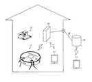
図1ないし図4において、11は自律走行体としての電気掃除機であり、この電気掃除機11は、この電気掃除機11の充電用の基地部となる基地装置としての充電装置(充電台)12とともに自律走行体装置としての電気掃除装置(電気掃除システム)を構成するものである。そして、電気掃除機11は、本実施形態において、走行面としての被掃除面である床面上を自律走行(自走)しつつ床面を掃除する、いわゆる自走式のロボットクリーナ(掃除ロボット)である。この電気掃除機11は、例えば掃除領域内などに配置された中継手段(中継部)としてのホームゲートウェイ(ルータ)14との間で有線通信あるいはWi−Fi(登録商標)やBluetooth(登録商標)などの無線通信を用いて通信(送受信)することにより、インターネットなどの(外部)ネットワーク15を介して、データ格納手段(データ格納部)としての汎用のサーバ16や、表示端末(表示部)である汎用の外部装置17などと有線あるいは無線通信可能となっている。 In FIGS. 1 to 4, 11 is an electric vacuum cleaner as an autonomous traveling body, and the
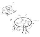
そして、この電気掃除機11は、中空状の本体ケース20を備えている。また、この電気掃除機11は、走行部21を備えている。さらに、この電気掃除機11は、塵埃を掃除する掃除部22を備えている。また、この電気掃除機11は、有線、あるいは無線によりネットワーク15を介して通信する情報送信手段としてのデータ通信手段(通信部)23を備えている。さらに、この電気掃除機11は、画像を撮像する撮像部24を備えている。さらに、この電気掃除機11は、センサ部25を備えている。また、この電気掃除機11は、コントローラである制御手段(制御部)26を備えている。さらに、この電気掃除機11は、画像処理プロセッサ(GPU)である画像処理手段(画像処理部)27を備えている。また、この電気掃除機11は、外部装置との間で信号が入出力される入出力部28を備えている。そして、この電気掃除機11は、給電用の電池である二次電池29を備えている。なお、以下、電気掃除機11(本体ケース20)の走行方向に沿った方向を前後方向(図2に示す矢印FR,RR方向)とし、この前後方向に対して交差(直交)する左右方向(両側方向)を幅方向として説明する。 The
本体ケース20は、例えば合成樹脂などにより形成されている。この本体ケース20は、例えば扁平な円柱状(円盤状)などに形成されていてもよい。また、この本体ケース20には、集塵口である吸込口31などが床面に対向する下部などに設けられていてもよい。 The
走行部21は、駆動部としての駆動輪34を備えている。また、この走行部21は、駆動輪34を駆動させる駆動手段である図示しないモータを備えている。すなわち、電気掃除機11は、駆動輪34と、この駆動輪34を駆動させるモータとを備えている。なお、この走行部21には、旋回用の旋回輪36などを備えていてもよい。 The
駆動輪34は、電気掃除機11(本体ケース20)を床面上で前進方向および後退方向に走行(自律走行)させる、すなわち走行用のものである。本実施形態では、この駆動輪34は、例えば本体ケース20の左右に一対設けられている。なお、この駆動輪34に代えて、駆動部としての無限軌道などを用いることもできる。 The
モータは、駆動輪34に対応して配置されている。したがって、本実施形態では、このモータは、例えば左右一対設けられている。そして、このモータは、各駆動輪34を独立して駆動させることが可能となっている。 The motors are arranged corresponding to the
掃除部22は、例えば床面や壁面などの被掃除部の塵埃を除去するものである。この掃除部22は、例えば床面上の塵埃を吸込口31から集めて捕集したり、壁面を拭き掃除したりする機能を有している。この掃除部22は、吸込口31から空気とともに塵埃を吸い込む電動送風機40と、吸込口31に回転可能に取り付けられて塵埃を掻き上げる回転清掃体としての回転ブラシ41およびこの回転ブラシ41を回転駆動させるブラシモータと、本体ケース20の前側などの両側に回転可能に取り付けられて塵埃を掻き集める旋回清掃部としての補助掃除手段(補助掃除部)であるサイドブラシ43およびこのサイドブラシ43を駆動させるサイドブラシモータとの少なくともいずれかを備えていてもよい。また、この掃除部22は、吸込口31と連通して塵埃を溜める集塵部を備えていてもよい。 The
データ通信手段23は、例えばホームゲートウェイ14およびネットワーク15を介して外部装置17と各種情報を送受信するための無線LANデバイスである。なお、例えばデータ通信手段23にアクセスポイント機能を搭載し、ホームゲートウェイ14を介さずに外部装置17と直接無線通信をするようにしてもよい。また、例えばデータ通信手段23にウェブサーバ機能を付加してもよい。 The data communication means 23 is a wireless LAN device for transmitting and receiving various information to and from the
撮像部24は、撮像手段(撮像部本体)としてのカメラ51を備えている。すなわち、電気掃除機11は、カメラ51を備えている。また、この撮像部24は、カメラ51に照明を付与する照明手段(照明部)としてのランプ53を備えていてもよい。すなわち、電気掃除機11は、ランプ53を備えていてもよい。 The
カメラ51は、本体ケース20の走行方向である前方を、それぞれ所定の水平画角(例えば105°など)でデジタルの画像を所定時間毎、例えば数十ミリ秒毎などの微小時間毎、あるいは数秒毎などに撮像するデジタルカメラである。このカメラ51は、単数でも複数でもよい。本実施形態では、カメラ51は、左右一対設けられている。すなわち、このカメラ51は、左右に離間されて本体ケース20の前部に配置されている。また、これらカメラ51,51は、互いの撮像範囲(視野)が重なっている。そのため、これらカメラ51,51により撮像される画像は、その撮像領域が左右方向にラップしている。なお、カメラ51により撮像する画像は、例えば可視光領域のカラー画像や白黒画像でもよいし、赤外線画像でもよい。また、カメラ51により撮像した画像は、例えば画像処理手段27などにより所定のデータ形式に圧縮することもできる。 The
ランプ53は、カメラ51により画像を撮像する際の照明用の光を出力するものである。このランプ53は、本実施形態では、カメラ51,51の中間位置に配置されている。このランプ53は、カメラ51により撮像する光の波長範囲に応じた光を出力するようになっている。したがって、このランプ53は、可視光領域を含む光を照明してもよいし、赤外光を照明してもよい。 The
センサ部25は、電気掃除機11(本体ケース20)の走行をサポートする各種の情報をセンシングするものである。より具体的に、このセンサ部25は、例えば床面の凹凸状態(段差)や、走行の障害となる壁あるいは障害物などをセンシングするものである。すなわち、このセンサ部25は、例えば赤外線センサや接触センサなどの段差センサ、障害物センサなどを備えている。なお、このセンサ部25は、例えば各駆動輪34(各モータ)の回転数を検出することで電気掃除機11(本体ケース20)の旋回角度や進行距離を検出する光エンコーダなどの回転数センサや、床面の塵埃量を検出する光センサなどの塵埃量センサなどをさらに備えていてもよい。 The
制御手段26は、例えば制御手段本体(制御部本体)であるCPUやROMおよびRAMなどを備えるマイコンが用いられる。この制御手段26は、図示しないが、走行部21と電気的に接続される走行制御部を備えている。また、この制御手段26は、図示しないが、掃除部22と電気的に接続される掃除制御部を備えている。さらに、この制御手段26は、図示しないが、センサ部25と電気的に接続されるセンサ接続部を備えている。また、この制御手段26は、図示しないが、画像処理手段27と電気的に接続される処理接続部を備えている。さらに、この制御手段26は、図示しないが、入出力部28と電気的に接続される入出力接続部を備えている。すなわち、この制御手段26は、走行部21、掃除部22、センサ部25、画像処理手段27および入出力部28と電気的に接続されている。また、この制御手段26は、二次電池29と電気的に接続されている。そして、この制御手段26は、例えば駆動輪34すなわちモータを駆動して電気掃除機11(本体ケース20)を自律走行させる走行モードと、充電装置12を介して二次電池29を充電する充電モードと、動作待機中の待機モードとを有している。 As the control means 26, for example, a microcomputer including a CPU, a ROM, a RAM, etc., which is a control means main body (control unit main body), is used. Although not shown, the control means 26 includes a travel control unit that is electrically connected to the
走行制御部は、走行部21のモータの動作を制御する、すなわち、モータに流れる電流の大きさおよび向きを制御することにより、モータを正転、あるいは逆転させることで、モータの動作を制御し、モータの動作を制御することで駆動輪34の動作を制御するものである。 The travel control unit controls the operation of the motor of the
掃除制御部は、掃除部22の電動送風機40、ブラシモータおよびサイドブラシモータの動作を制御する、すなわち、電動送風機40、ブラシモータ、および、サイドブラシモータの通電量をそれぞれ別個に制御することで、これら電動送風機40、ブラシモータ(回転ブラシ41)、および、サイドブラシモータ(サイドブラシ43)の動作を制御する。 The cleaning control unit controls the operation of the
センサ接続部は、センサ部25による検出結果を取得するものである。 The sensor connection unit acquires the detection result by the
処理接続部は、画像処理手段27による画像処理に基づき設定される設定結果を取得するものである。 The processing connection unit acquires a setting result set based on image processing by the image processing means 27.
入出力接続部は、入出力部28を介して制御コマンドを取得するとともに、入出力部28から出力する信号を入出力部28に出力するものである。 The input / output connection unit acquires control commands via the input /
画像処理手段27は、カメラ51により撮像された画像(生画像)を画像処理するものである。より具体的に、この画像処理手段27は、カメラ51により撮像された画像の中から画像処理によって特徴点を抽出することで障害物の距離および高さを検出して掃除領域の地図(マップ)を作成したり、電気掃除機11(本体ケース20(図2))の現在位置を推定したりするものである。そして、この画像処理手段27は、例えば画像処理手段本体(画像処理部本体)であるCPUやROMおよびRAMなどを備える画像処理エンジンである。この画像処理手段27は、図示しないが、カメラ51の動作を制御する撮像制御部を備えている。また、この画像処理手段27は、図示しないが、ランプ53の動作を制御する照明制御部を備えている。したがって、この画像処理手段27は、撮像部24と電気的に接続されている。さらに、この画像処理手段27は、記憶手段(記憶部)としてのメモリ61を備えている。すなわち、電気掃除機11は、メモリ61を備えている。また、この画像処理手段27は、カメラ51により撮像された生画像を補正した補正画像を作成する画像補正部62を備えている。すなわち、電気掃除機11は、画像補正部62を備えている。さらに、この画像処理手段27は、画像に基づき走行方向側に位置する物体までの距離を算出する距離算出手段(距離算出部)63を備えている。すなわち、電気掃除機11は、距離算出手段(距離算出部)63を備えている。また、この画像処理手段27は、距離算出手段63によって算出した物体までの距離に基づいて障害物を判定する障害物検出手段(障害物判定部)64を備えている。すなわち、電気掃除機11は、障害物検出手段(障害物判定部)64を備えている。また、この画像処理手段27は、電気掃除機11(本体ケース20)の自己位置を推定する自己位置推定手段(自己位置推定部)65を備えている。すなわち、電気掃除機11は、自己位置推定手段(自己位置推定部)65を備えている。さらに、この画像処理手段27は、走行場所である掃除領域の地図(マップ)を作成するマッピング手段(マッピング部)66を備えている。すなわち、電気掃除機11は、マッピング手段(マッピング部)66を備えている。また、この画像処理手段27は、電気掃除機11(本体ケース20)の走行計画(走行ルート)を設定する走行計画設定手段(走行計画設定部)67を備えている。すなわち、電気掃除機11は、走行計画設定手段(走行計画設定部)67を備えている。そして、この画像処理手段27は、電気掃除機11(本体ケース20)により掃除できなかった箇所を推定する未掃除箇所推定手段(未掃除箇所推定部)68を備えている。すなわち、電気掃除機11は、未掃除箇所推定手段(未掃除箇所推定部)68を備えている。 The image processing means 27 performs image processing on an image (raw image) captured by the
撮像制御部は、例えばカメラ51のシャッタの動作を制御する制御回路を備え、このシャッタを所定時間毎に動作させることで、所定時間毎にカメラ51により画像を撮像させるように制御する。 The image pickup control unit includes, for example, a control circuit for controlling the operation of the shutter of the
照明制御部は、例えばスイッチなどを介してランプ53のオンオフを制御している。 The lighting control unit controls the on / off of the
なお、これら撮像制御部および照明制御部は、画像処理手段27とは別個の撮像制御手段として構成してもよいし、例えば制御手段26に設けられていてもよい。 The image pickup control unit and the illumination control unit may be configured as an image pickup control means separate from the image processing means 27, or may be provided in, for example, the control means 26.
メモリ61は、例えばカメラ51で撮像した画像のデータや、マッピング手段66により作成された地図などの各種データを記憶する。このメモリ61としては、電気掃除機11の電源のオンオフに拘らず記憶した各種データを保持する、例えばフラッシュメモリなどの不揮発性のメモリが用いられる。 The memory 61 stores various data such as image data captured by the
画像補正部62は、カメラ51により撮像した生画像のレンズの歪み補正やノイズの除去、コントラスト調整、および画像中心の一致化などの一次画像処理をする。 The
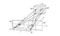
距離算出手段63は、既知の方法を用いて、カメラ51により撮像した画像、本実施形態では、カメラ51により撮像され画像補正部62によって補正された補正画像と、カメラ51間の距離とに基づいて物体(特徴点)の距離(深度)および三次元座標を計算する。すなわち、この距離算出手段63は、図5に示すように、例えばカメラ51の奥行きf、カメラ51とこのカメラ51により撮像された画像G1,G2の物体(特徴点)との距離(視差)、および、カメラ51間の距離lに基づく三角測量を応用し、カメラ51により撮像した各画像(画像補正部62(図1)によって処理された補正画像)中から同一位置を示す画素ドットを検出し、この画素ドットの上下方向、左右方向および前後方向の角度を計算して、これら角度とカメラ51間の距離とからその位置のカメラ51からの距離および高さを計算するとともに物体O(特徴点SP)の三次元座標を算出する。したがって、本実施形態において、複数のカメラ51により撮像する画像は、可能な限り範囲が重なって(ラップして)いることが好ましい。なお、この図1に示す距離算出手段63は、この計算した物体の距離を示す距離画像(視差画像)を作成してもよい。この距離画像の作成の際には、計算した各画素ドットの距離を、例えば1ドット毎などの所定ドット毎に明度、あるいは色調などの、視認により識別可能な階調に変換して表示することにより行われる。したがって、この距離画像は、いわば図2に示す電気掃除機11(本体ケース20)の走行方向前方のカメラ51によって撮像される範囲内に位置する物体の距離情報(距離データ)の集合体を可視化したものである。なお、特徴点は、図1に示す画像補正部62により補正された画像や距離画像に対して例えばエッジ検出などを行うことで抽出可能である。エッジ検出方法は、既知の任意の方法を用いることができる。 The distance calculation means 63 is based on an image captured by the
障害物検出手段64は、カメラ51により撮像された画像に基づいて障害物を検出する。より具体的に、この障害物検出手段64は、距離算出手段63により距離を算出した物体が障害物であるかどうかを判定する。すなわち、この障害物検出手段64は、距離算出手段63により計算した物体の距離から、所定の画像範囲中の部分を抽出し、この画像範囲中に撮像されている物体の距離を、予め設定された、あるいは可変設定された閾値である設定距離と比較し、この設定距離以下の距離(電気掃除機11(本体ケース20(図2))からの距離)に位置する物体を障害物であると判定する。上記の画像範囲は、例えば図2に示す電気掃除機11(本体ケース20)の上下左右の大きさに応じて設定される。すなわち、画像範囲は、電気掃除機11(本体ケース20)がそのまま直進したときに接触する範囲に上下左右が設定される。 The
図1に示す自己位置推定手段65は、距離算出手段63により算出した物体の特徴点の三次元座標に基づき、電気掃除機11の自己位置、および、障害物となる物体の有無を判断するものである。また、マッピング手段66は、距離算出手段63により算出した特徴点の三次元座標に基づき、電気掃除機11(本体ケース20(図2))が配置された掃除領域内に位置する物体(障害物)などの位置関係および高さを記す地図を作成する。すなわち、自己位置推定手段65およびマッピング手段66には、既知のSLAM(simultaneous localization and mapping)技術を用いることができる。 The self-position estimation means 65 shown in FIG. 1 determines the self-position of the
マッピング手段66は、距離算出手段63および自己位置推定手段65の算出結果に基づいて走行場所の地図を三次元データにより作成するものである。このマッピング手段66は、本実施形態において、第1のマッピング手段66aと、第2のマッピング手段66bとを備えている。 The mapping means 66 creates a map of the traveling place by three-dimensional data based on the calculation results of the distance calculation means 63 and the self-position estimation means 65. In the present embodiment, the mapping means 66 includes a first mapping means 66a and a second mapping means 66b.
第1のマッピング手段66aは、カメラ51により撮像した画像、すなわち距離算出手段63により算出された物体の三次元データに基づき、任意の方法を用いて簡易的な地図を作成するものである。本実施形態では、第1のマッピング手段66aは、例えば、制御手段26により本体ケース20(図2)を走行制御しつつカメラ51により撮像した画像に基づいて、簡易的な地図を作成する。より具体的に、第1のマッピング手段66aは、例えば、制御手段26により本体ケース20(図2)を所定位置で旋回させるように走行制御しつつカメラ51により撮像した画像(画像補正部62により補正した補正画像)に基づき、距離算出手段63により算出した特徴点の三次元座標のx軸成分(左右成分)およびz軸成分(前後成分)から、簡易的な地図を作成する。例えば、この第1のマッピング手段66aは、掃除を開始する際に簡易的な地図を作成する。このとき、第1のマッピング手段66aは、メモリ61に地図が記憶されていない場合に簡易的な地図を作成する。すなわち、メモリ61に地図が記憶されている場合には、第1のマッピング手段66aによるマッピングは不要となる。 The first mapping means 66a creates a simple map by using an arbitrary method based on the image captured by the
第2のマッピング手段66bは、カメラ51により撮像した画像、すなわち距離算出手段63により算出された物体の三次元データを地図に追加反映させるものである。すなわち、この第2のマッピング手段66bは、距離算出手段63により算出した特徴点の三次元座標のうち、y軸成分(上下成分)から、電気掃除機11(本体ケース20(図2))が配置された掃除領域内に位置する物体(障害物)などの二次元位置および高さを第1のマッピング手段66aにより簡易的に作成された地図である簡易地図、あるいはメモリ61に記憶された地図に詳細情報を追加する。この詳細情報とは、例えばカーペットの厚みや、ベッド下部の高さなどである。なお、本実施形態において、マッピング手段66により作成する地図とは、メモリ61などに展開されたデータをいうものとする。すなわち、この地図のデータは、三次元データ、すなわち物体の二次元配置位置データおよび高さデータにより構成されている。また、この地図のデータは、掃除の際の電気掃除機11(本体ケース20(図2))の走行軌跡を記す走行軌跡データをさらに含んでいてもよい。 The second mapping means 66b additionally reflects the image captured by the
走行計画設定手段67は、マッピング手段66により作成した地図、および、自己位置推定手段65により推定した自己位置に基づいて、最適な走行ルートを設定する。ここで、作成する最適な走行ルートとしては、地図中の掃除可能な領域(障害物や段差などの走行不能な領域を除く領域)を最短の走行距離で走行できるルート、例えば電気掃除機11(本体ケース20(図2))が可能な限り直進する(方向転換が最も少ない)ルート、障害物となる物体への接触が少ないルート、あるいは、同じ箇所を重複して走行する回数が最小となるルートなど、効率的に走行(掃除)を行うことができるルートが設定される。また、この走行計画設定手段67は、走行ルートを設定する際、地図(簡易地図)に基づき掃除領域の形状や広さを把握し、初めに掃除する場所を設定したり、掃除に必要となると想定される二次電池29の容量を確認したり、掃除領域を分割したりするようにしてもよい。なお、本実施形態において、走行計画設定手段67により設定する走行ルートは、メモリ61などに展開されたデータ(走行ルートデータ)をいうものとする。 The travel plan setting means 67 sets an optimum travel route based on the map created by the mapping means 66 and the self-position estimated by the self-position estimation means 65. Here, as the optimum travel route to be created, a route that can travel in the shortest mileage in a cleanable area (area excluding non-travelable areas such as obstacles and steps) in the map, for example, the vacuum cleaner 11 ( The route in which the main body case 20 (Fig. 2)) goes straight as much as possible (with the least number of changes in direction), the route with less contact with obstacles, or the number of times the same location is duplicated is minimized. A route that allows efficient driving (cleaning), such as a route, is set. In addition, when setting the travel route, the travel plan setting means 67 grasps the shape and size of the cleaning area based on the map (simple map), sets the place to be cleaned first, and is required for cleaning. The expected capacity of the
未掃除箇所推定手段68は、三次元データと本体ケース20(図2)の走行軌跡データとに基づき、掃除できなかった場所を推定するものである。すなわち、この未掃除箇所推定手段68は、地図を示す三次元データと、本体ケース20(図2)の走行軌跡データとを比較し、電気掃除機11(本体ケース20(図2))が走行可能な領域のうち走行軌跡が形成されなかった箇所を、掃除できなかった場所として推定する。この掃除できなかった場所は、マッピング手段66により作成した地図に反映することができる。 The uncleaned portion estimating means 68 estimates a location that could not be cleaned based on the three-dimensional data and the traveling locus data of the main body case 20 (FIG. 2). That is, the uncleaned portion estimating means 68 compares the three-dimensional data showing the map with the traveling locus data of the main body case 20 (FIG. 2), and the vacuum cleaner 11 (main body case 20 (FIG. 2)) travels. Of the possible areas, the part where the traveling locus was not formed is estimated as the part that could not be cleaned. This uncleaned place can be reflected in the map created by the mapping means 66.
入出力部28は、図示しないリモコンなどの外部装置から送信される制御コマンドや、本体ケース20(図2)に設けられたスイッチ、あるいはタッチパネルなどの入力手段から入力される制御コマンドを取得するとともに、例えば充電装置12(図2)などに対して信号を送信するものである。この入出力部28は、例えば充電装置12(図2)などへと無線信号(赤外線信号)を送信する例えば赤外線発光素子などの図示しない送信手段(送信部)、および、充電装置12(図2)やリモコンなどからの無線信号(赤外線信号)を受信する例えばフォトトランジスタなどの図示しない受信手段(受信部)などを備えている。 The input /
二次電池29は、走行部21、掃除部22、データ通信手段23、撮像部24、センサ部25、制御手段26、画像処理手段27、および、入出力部28などに給電するものである。また、この二次電池29は、例えば本体ケース20(図2)の下部などに露出する接続部としての充電端子71(図3)と電気的に接続されており、これら充電端子71(図3)が充電装置12(図2)側と電気的および機械的に接続されることで、この充電装置12(図2)を介して充電されるようになっている。 The
図2に示す充電装置12は、例えば定電流回路などの充電回路を内蔵している。また、この充電装置12には、二次電池29(図1)の充電用の充電用端子73が設けられている。この充電用端子73は、充電回路と電気的に接続されており、充電装置12に帰還した電気掃除機11の充電端子71(図3)と機械的および電気的に接続されるようになっている。 The charging
図4に示すホームゲートウェイ14は、アクセスポイントなどとも呼ばれ、建物内に設置され、ネットワーク15に対して例えば有線により接続されている。 The
サーバ16は、ネットワーク15に接続されたコンピュータ(クラウドサーバ)であり、各種データを保存可能である。 The
外部装置17は、建物の内部では例えばホームゲートウェイ14を介してネットワーク15に対して有線あるいは無線通信可能であるとともに、建物の外部ではネットワーク15に対して有線あるいは無線通信可能な、例えばPC(タブレット端末(タブレットPC))やスマートフォン(携帯電話)などの汎用のデバイスである。この外部装置17は、少なくとも画像を表示する表示機能を有している。 The
次に、上記一実施形態の動作を、図面を参照しながら説明する。 Next, the operation of the above embodiment will be described with reference to the drawings.
一般に、電気掃除装置は、電気掃除機11によって掃除をする掃除作業と、充電装置12によって二次電池29を充電する充電作業とに大別される。充電作業は、充電装置12に内蔵された充電回路を用いる既知の方法が用いられるため、掃除作業についてのみ説明する。また、外部装置17などからの指令に応じてカメラ51により所定の対象物を撮像する撮像作業を別途備えていてもよい。 Generally, the electric cleaning device is roughly classified into a cleaning work of cleaning by the
まず、掃除の開始から終了までの概略を説明する。電気掃除機11は、掃除開始を開始すると充電装置12から離脱し、メモリ61に地図が記憶されていない場合にはカメラ51により撮像した画像に基づいて第1のマッピング手段66aにより簡易的な地図を作成し、この簡易的な地図に基づいて走行計画設定手段67により設定された走行ルートに沿って走行するように制御手段26が電気掃除機11(本体ケース20)を制御しながら掃除部22により掃除をする。メモリ61に地図が記憶されている場合には、この地図に基づいて走行計画設定手段67により設定された走行ルートに沿って走行するように制御手段26が電気掃除機11(本体ケース20)を制御しながら掃除部22により掃除をする。この掃除の最中に、カメラ51により撮像した画像に基づいて第2のマッピング手段66bにより物体の二次元配置位置および高さを検出し、地図に反映させてメモリ61に記憶していく。そして、掃除が終了すると、制御手段26が電気掃除機11(本体ケース20)を充電装置12へと帰還させるように走行制御し、充電装置12に帰還した後、所定のタイミングで二次電池29の充電作業に移行する。 First, the outline from the start to the end of cleaning will be described. When the
より詳細に、電気掃除機11は、例えば予め設定された掃除開始時刻となったときや、リモコンまたは外部装置17によって送信された掃除開始の制御コマンドを入出力部28によって受信したときなどのタイミングで、制御手段26が待機モードから走行モードに切り換わり、この制御手段26(走行制御部)がモータ(駆動輪34)を駆動させ充電装置12から所定距離離脱する。 More specifically, the
次いで、電気掃除機11は、メモリ61を参照し、メモリ61に地図が記憶されているか否かを判断する。メモリ61に地図が記憶されていない場合には、マッピング手段66の第1のマッピング手段66aにより、掃除領域の簡易地図を作成し、この簡易地図に基づいて走行計画設定手段67により最適な走行ルートを作成する。 Next, the
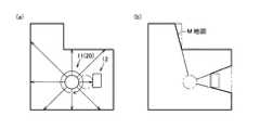
簡易地図の作成の際には、概略として、電気掃除機11は、充電装置12から離脱した位置で旋回(超信地旋回)しながら、カメラ51により撮像した画像に基づいて物体(壁や障害物など)の二次元配置位置データおよび高さデータを取得して、簡易地図を作成する(簡易地図作成モード)。そして、掃除領域全体の簡易地図を作成すると、簡易地図作成モードを終了し、後述する掃除モードに移行する。 When creating a simple map, as a general rule, the
より具体的に、例えば図6(a)に示すように、電気掃除機11(本体ケース20)が充電装置12に接続された状態から、充電装置12から所定距離離脱した後、所定角度旋回(超信地旋回)しつつカメラ51(図2)によって画像を撮像する。このとき、電気掃除機11(本体ケース20)の旋回角度は、例えば360°とする。そして、撮像された物体(特徴点)の電気掃除機11(本体ケース20)からの距離と、現在の電気掃除機11(本体ケース20)の位置とにより障害物の位置(二次元座標)を認識して、図6(b)に示すように地図M(図中の太線に示す)を作成する。このとき、カメラ51(図2)の死角となる位置については、障害物または壁であるものとして処理する。 More specifically, for example, as shown in FIG. 6A, after the vacuum cleaner 11 (main body case 20) is connected to the charging
一方、メモリ61に予め地図が記憶されている場合には、簡易地図を作成せず、メモリ61に記憶されている地図に基づいて、走行計画設定手段67により最適な走行ルートを作成する。 On the other hand, when the map is stored in the memory 61 in advance, the simple map is not created, and the optimum travel route is created by the travel plan setting means 67 based on the map stored in the memory 61.
そして、走行計画設定手段67により作成した走行ルートに沿って、電気掃除機11は掃除領域内を自律走行しつつ掃除をする(掃除モード)。この掃除モードにおいて、掃除部22では、例えば制御手段26(掃除制御部)により駆動された電動送風機40、ブラシモータ(回転ブラシ41)、あるいはサイドブラシモータ(サイドブラシ43)により床面の塵埃を、吸込口31を介して集塵部へと捕集する。 Then, the
自律走行の際には、概略として、電気掃除機11は、掃除部22を動作させながら、走行ルートに沿って進みながらカメラ51により進行方向前方の画像を撮像しつつ、障害物検出手段64により障害物となる物体を検出するとともにセンサ部25により周辺をセンシングし、自己位置推定手段65によって定期的に自己位置を推定する動作を繰り返していく。このとき、カメラ51により撮像した画像に基づいて、マッピング手段66の第2のマッピング手段66bが特徴点の詳細情報(高さデータ)を地図に反映させることで地図を完成していく。また、自己位置推定手段65による電気掃除機11(本体ケース20)の自己位置の推定により、電気掃除機11(本体ケース20)の走行軌跡データを作成することもできる。 In the case of autonomous traveling, as a general rule, the
設定された走行ルートを完走すると、電気掃除機11は、充電装置12に帰還する。そして、この帰還の直後や、帰還から所定時間経過したとき、あるいは所定時刻になったときなど、適宜のタイミングで制御手段26が走行モードから充電モードに切り換わって、二次電池29の充電に移行する。 When the set travel route is completed, the
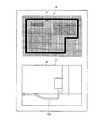
なお、完成した地図Mは、図7に視覚的に示すように、掃除領域(部屋)が所定の大きさの四角形状(正方形状)などのメッシュに分割され、メッシュ毎に高さデータが関連付けられて記憶されている。物体の高さは、カメラ51により撮像した画像に基づいて距離算出手段63により取得される。例えば、図7に示す地図Mは、床面に凸段差を生じさせる障害物であるカーペットC、電気掃除機11(本体ケース20)が下部に進入可能な高さを有する障害物であるベッドB、電気掃除機11(本体ケース20)が下部に進入可能な高さを有する障害物であるソファS、走行不可能な障害物である棚R、ベッドBやソファSの障害物である脚部LG、および、掃除領域を囲む走行不可能な障害物である壁Wなどを有している。この地図のデータは、メモリ61だけでなく、データ通信手段23を介して、ネットワーク15を経由してサーバ16に送信して記憶したり、外部装置17に送信して外部装置17のメモリに記憶したりすることができる。 In the completed map M, as visually shown in FIG. 7, the cleaning area (room) is divided into meshes such as a square shape (square shape) having a predetermined size, and height data is associated with each mesh. It is remembered. The height of the object is acquired by the distance calculating means 63 based on the image captured by the
そして、以上説明した一実施形態によれば、カメラ51によって撮像した画像に基づいて走行方向側に位置する物体までの距離を算出し、カメラ51によって撮像した画像に基づいて本体ケース20の位置を算出するとともに、これらの算出結果に基づいて走行場所の地図を三次元データにより作成し、この作成された地図の三次元データに基づいて駆動輪34(モータ)の動作を制御することで本体ケース20を自律走行させることにより、地図の作成精度を向上し、三次元データに基づいて走行障害の判断が容易になる。この結果、電気掃除機11(本体ケース20)を掃除領域に応じて、より隅々まできめ細かく走行制御することができ、効率よく掃除できる。 Then, according to one embodiment described above, the distance to the object located on the traveling direction side is calculated based on the image captured by the
具体的に、三次元データは、物体の二次元配置位置データおよび高さデータからなることで、例えば電気掃除機11(本体ケース20)がベッドの下に進入できるか、あるいは電気掃除機11(本体ケース20)がカーペットなどの段差を走行できるかなどの判断が容易になる。 Specifically, the three-dimensional data consists of two-dimensional placement position data and height data of an object, so that, for example, the vacuum cleaner 11 (main body case 20) can enter under the bed, or the vacuum cleaner 11 (main body case 20). It becomes easy to judge whether the main body case 20) can run on a step such as a carpet.
したがって、例えば床面にカーペットが敷かれていることを判断した場合には、非カーペット面とカーペット面とで掃除方法を異ならせることで、掃除性能を向上させることができる。具体的に、例えば非カーペット面では、電動送風機40による吸込力を低下させて消費電力を抑制し、二次電池29を長持ちさせることができ、カーペット面では、走行速度を低速とし、かつ、電動送風機40による吸込力を増加させるように制御手段26が制御することで、カーペットに付着した塵埃を、掃除部22によってより除去しやすくできる。 Therefore, for example, when it is determined that the carpet is laid on the floor surface, the cleaning performance can be improved by making the cleaning method different between the non-carpet surface and the carpet surface. Specifically, for example, on the non-carpet surface, the suction force of the
マッピング手段66は、カメラ51により撮像した画像に基づいて簡易的に地図を作成する第1のマッピング手段66aと、カメラ51により撮像された物体の三次元データを地図に追加反映させる第2のマッピング手段66bとを備えているので、簡易的に作成した地図によって、走行計画設定手段67が初期段階で走行ルートを設定する際などに、この簡易地図に基づき掃除領域の形状や広さを把握することができ、初めに掃除する場所を設定したり、掃除に必要となると想定される二次電池29の容量を確認したり、掃除領域を分割したりするなどの判断が容易になるとともに、掃除を継続するに従い地図の精度が向上していくので、最終的に作成された地図が高精度のものとなり、次回以降の掃除の際に有効に利用することができる。 The mapping means 66 includes a first mapping means 66a that simply creates a map based on an image captured by the
第1のマッピング手段66aは、制御手段26が本体ケース20を旋回させるように駆動輪34(モータ)の動作を制御してカメラ51により撮像した画像に基づいて簡易地図を作成するので、短時間で容易に簡易的な地図を作成できる。 The first mapping means 66a controls the operation of the drive wheels 34 (motor) so that the control means 26 turns the
また、地図のデータを記憶するメモリ61を備えることにより、2回目以降の掃除の際には、前回の掃除の際に作成した地図に基づいて走行ルートなどを容易に設定でき、掃除を直ちに開始できる。 In addition, by providing a memory 61 that stores map data, it is possible to easily set a travel route based on the map created during the previous cleaning during the second and subsequent cleanings, and cleaning starts immediately. it can.
そして、上記マッピング手段66により作成された地図は、本実施形態において、例えば以下のように応用することが可能である。 Then, the map created by the mapping means 66 can be applied in the present embodiment as follows, for example.
例えば、データ通信手段23が、ネットワーク15に接続されている外部装置17に対してネットワーク15を介して地図のデータを送信することで、地図を外部装置17に例えばリアルタイムで表示させることができる。 For example, the data communication means 23 can display the map on the
また、データ通信手段23は、ネットワーク15に接続されているサーバ16に対してネットワーク15を介して地図のデータを送受信することで、前回の掃除の際に作成した地図をサーバ16に記憶し、必要に応じてこのサーバ16から読み出すことができるので、例えばメモリ61を電気掃除機11に設けない構成とすることもできる。 In addition, the data communication means 23 sends and receives map data to and from the
また、地図のデータに、三次元データと、本体ケース20の走行軌跡データとを備えることで、物体の三次元データと本体ケース20の走行軌跡データとを反映した地図を外部装置17にリアルタイムで表示させることができる。 Further, by providing the map data with the three-dimensional data and the traveling locus data of the
そして、三次元データと本体ケース20の走行軌跡データとに基づき、未掃除箇所推定手段68が掃除できなかった場所を推定することで、例えば掃除できなかった箇所を地図に表示させることが可能になる。 Then, by estimating the place where the uncleaned part estimation means 68 could not be cleaned based on the three-dimensional data and the traveling locus data of the
特に、この推定された掃除できなかった場所の画像をカメラ51により撮像する、より詳細には掃除できなかった場所の画像をカメラ51により撮像可能な場所へと制御手段26が電気掃除機11(本体ケース20)を走行させるように駆動輪34(モータ)の動作を制御することで、掃除できなかった箇所を所有者に対して視覚的に明確に伝達することができる。 In particular, the control means 26 takes the image of the estimated uncleanable place with the
そして、この推定結果をデータ通信手段23によりネットワーク15を介して送信することで、ネットワーク15に接続された外部装置17に、例えば図8に示すように、掃除できなかった場所Pを反映した地図Mと、掃除できなかった場所の具体的な画像Gとをそれぞれ表示することが可能になる。この例では、例えば床面に沿って壁Wから突出したケーブルCBと壁Wとにより囲まれた部分が掃除できなかった場所P(電気掃除機11(本体ケース20)が接近して走行できなかった場所)となっている。そのため、この掃除できなかった場所を自分で掃除したり、次回の掃除の際にその場所を電気掃除機11によって自動掃除可能となるように掃除領域を片付けたりするなどの、所有者の自主的な掃除への参加を促すことができる。 Then, by transmitting this estimation result via the
制御手段26が、外部装置17から送信される制御コマンドに基づいて電気掃除機11(本体ケース20)を走行させるように駆動輪34(モータ)の動作を制御することで、例えば外部装置17に表示された地図を参照して所有者が電気掃除機11(本体ケース20)を所望の場所に走行させる制御コマンドなどを入力して、電気掃除機11(本体ケース20)を任意に遠隔操作することが可能になる。 The control means 26 controls the operation of the drive wheels 34 (motor) so as to drive the vacuum cleaner 11 (main body case 20) based on the control command transmitted from the
具体的に、制御コマンドは、地図上において移動させたい場所に制御手段26が本体ケース20を走行させるように駆動輪34(モータ)の動作を制御するための走行制御情報を含むことで、例えば外部装置17に表示された地図の所望の位置をタップするなど、地図上の所望の箇所を画面で示すだけの簡単な操作によって、その所望の箇所へと所有者が電気掃除機11(本体ケース20)を誘導する指示を出すことが可能になる。 Specifically, the control command includes, for example, travel control information for controlling the operation of the drive wheels 34 (motor) so that the control means 26 travels the
また、制御コマンドは、地図上において制御手段26が本体ケース20を進入させたくない場所へと走行させないように駆動輪34(モータ)の動作を制御するための走行制御情報を含むことで、例えば外部装置17に表示された地図上の所望の位置を、ラインを引くことなどによって地図上に示すだけの簡単な操作によって、その所望の位置へと所有者が電気掃除機11(本体ケース20)を進入させないように誘導する指示を出すことが可能になる。 Further, the control command includes, for example, travel control information for controlling the operation of the drive wheels 34 (motor) so that the control means 26 does not travel to a place where the
なお、上記一実施形態において、距離算出手段63は、複数(一対)のカメラ51によりそれぞれ撮像した画像を用いて特徴点の三次元座標を算出したが、例えば1つのカメラ51を用い、本体ケース20を移動させながら時分割で撮像した複数の画像を用いて特徴点の三次元座標を算出することもできる。 In the above embodiment, the distance calculation means 63 calculates the three-dimensional coordinates of the feature points using the images captured by each of the plurality of (pair)
本発明の一実施形態を説明したが、この実施形態は、例として提示したものであり、発明の範囲を限定することは意図していない。この新規な実施形態は、その他の様々な形態で実施されることが可能であり、発明の要旨を逸脱しない範囲で、種々の省略、置き換え、変更を行うことができる。この実施形態やその変形は、発明の範囲や要旨に含まれるとともに、特許請求の範囲に記載された発明とその均等の範囲に含まれる。 Although one embodiment of the present invention has been described, this embodiment is presented as an example and is not intended to limit the scope of the invention. This novel embodiment can be implemented in various other embodiments, and various omissions, replacements, and changes can be made without departing from the gist of the invention. This embodiment and its modifications are included in the scope and gist of the invention, and are also included in the scope of the invention described in the claims and the equivalent scope thereof.
11 電気掃除機
15 ネットワーク
16 サーバ
17 表示端末である外部装置
20 本体ケース
23 情報送信手段としてのデータ通信手段
26 制御手段
34 駆動部としての駆動輪
51 撮像手段としてのカメラ
61 記憶手段としてのメモリ
63 距離算出手段
65 自己位置推定手段
66 マッピング手段
66a 第1のマッピング手段
66b 第2のマッピング手段
68 未掃除箇所推定手段
M 地図11 vacuum cleaner
15 network
16 server
17 External device that is a display terminal
20 Body case
23 Data communication means as information transmission means
26 Control means
34 Drive wheels as a drive unit
51 Camera as an imaging means
61 Memory as a means of storage
63 Distance calculation means
65 Self-position estimation means
66 Mapping means
66a First mapping means
66b Second mapping means
68 Uncleaned area estimation method M map
Claims (12)
Translated fromJapaneseこの本体ケースを走行可能とする駆動部と、
前記本体ケースに配置され、前記本体ケースの走行方向側を撮像する撮像手段と、
この撮像手段によって撮像した画像に基づいて前記走行方向側に位置する物体までの距離を算出する距離算出手段と、
前記撮像手段によって撮像した画像に基づいて前記本体ケースの位置を算出する自己位置推定手段と、
これら距離算出手段および自己位置推定手段の算出結果に基づいて走行場所の地図を三次元データにより作成するマッピング手段と、
このマッピング手段により作成された地図の三次元データに基づいて前記駆動部の動作を制御することで前記本体ケースを自律走行させる制御手段とを具備し、
前記マッピング手段は、
所定位置で前記撮像手段により撮像された画像から前記距離算出手段および前記自己位置推定手段の算出結果から取得された物体の二次元配置位置データに基づき、前記制御手段が前記本体ケースを走行させる走行ルートを設定するための前記走行場所の二次元の簡易的な地図を作成する第1のマッピング手段と、
前記走行ルートに沿って前記本体ケースが走行しているときに前記撮像手段により撮像された画像から前記距離算出手段および前記自己位置推定手段の算出結果から取得された物体の高さデータを含む三次元データを前記簡易的な地図に追加反映させる第2のマッピング手段とを備えている
ことを特徴とした電気掃除機。With the main body case
The drive unit that enables this main body case to run,
An imaging means that is arranged in the main body case and images the traveling direction side of the main body case.
A distance calculating means for calculating the distance to an object located on the traveling direction side based on an image captured by the imaging means, and a distance calculating means.
A self-position estimation means that calculates the position of the main body case based on the image captured by the imaging means, and
A mapping means that creates a map of the travel location from three-dimensional data based on the calculation results of these distance calculation means and self-position estimation means, and
It is provided with a control means for autonomously traveling the main body case by controlling the operation of the drive unit based on the three-dimensional data of the map created by the mapping means.
The mapping means
Based on the two-dimensional arrangement position data of the object acquired from the calculation results of the distance calculation means and the self-position estimation means from the image captured by the imaging means at a predetermined position, the control means travels the main body case. A first mapping means for creating a simple two-dimensional map of the travel location for setting a route, and
A tertiary including height data of an object acquired from the calculation results of the distance calculating means and the self-position estimating means from the image captured by the imaging means while the main body case is traveling along the traveling route. A vacuum cleaner characterizedby having a second mapping means for additionally reflecting the original data on the simple map.
ことを特徴とした請求項1記載の電気掃除機。The first mapping means is characterized in that the control means controls the operation of the drive unit so as to rotate the main body case at apredetermined position and creates a simple map based on the image captured by the imaging means. The vacuum cleaner according to claim1 .
ことを特徴とした請求項1または2記載の電気掃除機。The vacuum cleaner according to claim 1or 2 , wherein the vacuum cleaner is provided with a storage means for storing map data.
ことを特徴とした請求項1ないし3いずれか一記載の電気掃除機。The vacuum cleaner according to any one of claims 1 to3, wherein the vacuum cleaner is provided with a data communication means for transmitting map data to a display terminal via a network.
ことを特徴とした請求項4記載の電気掃除機。The vacuum cleaner according to claim4 , wherein the data communication means transmits and receives map data to and from a server connected to the network via the network.
ことを特徴とした請求項1ないし5いずれか一記載の電気掃除機。The vacuum cleaner according to any one of claims 1 to5 , wherein the map data includes three-dimensional data and traveling locus data of the main body case.
ことを特徴とした請求項6記載の電気掃除機。The vacuum cleaner according to claim6 , further comprising an uncleaned portion estimating means for estimating a location that could not be cleaned based on three-dimensional data and travel locus data of the main body case.
ことを特徴とした請求項7記載の電気掃除機。The vacuum cleaner according to claim7 , wherein the imaging means captures an image of a location estimated by the uncleaned portion estimating means.
ことを特徴とした請求項7または8記載の電気掃除機。The vacuum cleaner according to claim7 or8 , further comprising an information transmitting means for transmitting an estimation result by an uncleaned portion estimating means to a network by communication.
ことを特徴とした請求項1ないし9いずれか一記載の電気掃除機。The vacuum cleaner according to any one of claims 1 to9 , wherein the control means controls the operation of the drive unit so as to drive the main body case based on a control command transmitted from an external device.
ことを特徴とした請求項10記載の電気掃除機。The vacuum cleaner according to claim10 , wherein the control command includes travel control information for controlling the operation of the drive unit so that the control means travels the main body case to a place to be moved on the map.
ことを特徴とした請求項10または11記載の電気掃除機。The control command according to claim10 or11 , wherein the control command includes travel control information for controlling the operation of the drive unit so that the control means does not travel to a place where the main body case is not desired to enter on the map. Electric vacuum cleaner.
Priority Applications (6)
| Application Number | Priority Date | Filing Date | Title |
|---|---|---|---|
| JP2016215460AJP6831210B2 (en) | 2016-11-02 | 2016-11-02 | Vacuum cleaner |
| US16/346,657US11119484B2 (en) | 2016-11-02 | 2017-06-07 | Vacuum cleaner and travel control method thereof |
| PCT/JP2017/021204WO2018083831A1 (en) | 2016-11-02 | 2017-06-07 | Electric vacuum cleaner |
| GB1906013.6AGB2569926A (en) | 2016-11-02 | 2017-06-07 | Electric vacuum cleaner |
| CN201780064391.5ACN109843139B (en) | 2016-11-02 | 2017-06-07 | Electric vacuum cleaner |
| TW106122153ATWI664948B (en) | 2016-11-02 | 2017-07-03 | Electric sweeper |
Applications Claiming Priority (1)
| Application Number | Priority Date | Filing Date | Title |
|---|---|---|---|
| JP2016215460AJP6831210B2 (en) | 2016-11-02 | 2016-11-02 | Vacuum cleaner |
Publications (2)
| Publication Number | Publication Date |
|---|---|
| JP2018068896A JP2018068896A (en) | 2018-05-10 |
| JP6831210B2true JP6831210B2 (en) | 2021-02-17 |
Family
ID=62075979
Family Applications (1)
| Application Number | Title | Priority Date | Filing Date |
|---|---|---|---|
| JP2016215460AActiveJP6831210B2 (en) | 2016-11-02 | 2016-11-02 | Vacuum cleaner |
Country Status (6)
| Country | Link |
|---|---|
| US (1) | US11119484B2 (en) |
| JP (1) | JP6831210B2 (en) |
| CN (1) | CN109843139B (en) |
| GB (1) | GB2569926A (en) |
| TW (1) | TWI664948B (en) |
| WO (1) | WO2018083831A1 (en) |
Families Citing this family (14)
| Publication number | Priority date | Publication date | Assignee | Title |
|---|---|---|---|---|
| US11503972B2 (en)* | 2017-03-03 | 2022-11-22 | Techtronic Floor Care Technology Limited | Vacuum cleaner and vacuum cleaning system in wireless communication with a user-controlled electronic device |
| US11348269B1 (en)* | 2017-07-27 | 2022-05-31 | AI Incorporated | Method and apparatus for combining data to construct a floor plan |
| CN108873879B (en)* | 2017-09-25 | 2022-03-04 | 北京石头创新科技有限公司 | Autonomous mobile robot and its pile finding method, control device and intelligent cleaning system |
| CN108852174B (en) | 2017-09-25 | 2022-02-25 | 北京石头创新科技有限公司 | Autonomous mobile robot and pile searching method, control device and intelligent cleaning system thereof |
| DE102018114892B4 (en)* | 2018-06-20 | 2023-11-09 | RobArt GmbH | Autonomous mobile robot and method for controlling an autonomous mobile robot |
| JP7281707B2 (en)* | 2018-07-06 | 2023-05-26 | パナソニックIpマネジメント株式会社 | Mobile robot and control method |
| EP3660617A4 (en)* | 2018-08-14 | 2021-04-14 | Chiba Institute of Technology | MOBILE ROBOT |
| JP7414285B2 (en)* | 2018-12-17 | 2024-01-16 | Groove X株式会社 | Robots and charging stations and landmark devices for robots |
| CN111603100B (en)* | 2020-05-08 | 2022-04-22 | 美智纵横科技有限责任公司 | Storage and reuse method and storage and reuse device for sweeping drawing of sweeper |
| CN112190185B (en)* | 2020-09-28 | 2022-02-08 | 深圳市杉川机器人有限公司 | Floor sweeping robot, three-dimensional scene construction method and system thereof, and readable storage medium |
| KR20220072146A (en)* | 2020-11-25 | 2022-06-02 | 삼성전자주식회사 | Electronic apparatus and controlling method thereof |
| CN112731936A (en)* | 2020-12-28 | 2021-04-30 | 上海有个机器人有限公司 | Method, device, medium and intelligent terminal for scanning remote-controlled robot |
| CN117008599A (en)* | 2023-02-27 | 2023-11-07 | 北京石头创新科技有限公司 | Path planning method, related equipment and robot of path planning method |
| KR20250111998A (en)* | 2024-01-16 | 2025-07-23 | 삼성전자주식회사 | Robotic vacuum cleaners managing non-entranceable areas and their methods |
Family Cites Families (32)
| Publication number | Priority date | Publication date | Assignee | Title |
|---|---|---|---|---|
| JPS5943009B2 (en)* | 1977-07-30 | 1984-10-19 | ソニー株式会社 | signal receiving device |
| JP3986310B2 (en)* | 2001-12-19 | 2007-10-03 | シャープ株式会社 | Parent-child type vacuum cleaner |
| JP4243594B2 (en)* | 2005-01-31 | 2009-03-25 | パナソニック電工株式会社 | Cleaning robot |
| KR100843085B1 (en) | 2006-06-20 | 2008-07-02 | 삼성전자주식회사 | Grid map preparation method and device of mobile robot and method and device for area separation |
| US8961695B2 (en)* | 2008-04-24 | 2015-02-24 | Irobot Corporation | Mobile robot for cleaning |
| CN201573208U (en)* | 2009-06-16 | 2010-09-08 | 泰怡凯电器(苏州)有限公司 | Device and robot for simultaneous localization and map creation of indoor service robots |
| DE102009052629A1 (en)* | 2009-11-10 | 2011-05-12 | Vorwerk & Co. Interholding Gmbh | Method for controlling a robot |
| KR20110119118A (en)* | 2010-04-26 | 2011-11-02 | 엘지전자 주식회사 | Robot cleaner, and remote monitoring system using the same |
| KR101677634B1 (en) | 2010-07-12 | 2016-11-18 | 엘지전자 주식회사 | Robot cleaner and controlling method of the same |
| JP2014048842A (en)* | 2012-08-30 | 2014-03-17 | Brother Ind Ltd | Autonomous mobile device |
| CN103885443B (en)* | 2012-12-20 | 2017-02-08 | 联想(北京)有限公司 | Device, system and method for simultaneous localization and mapping unit |
| JP6132659B2 (en) | 2013-02-27 | 2017-05-24 | シャープ株式会社 | Ambient environment recognition device, autonomous mobile system using the same, and ambient environment recognition method |
| JP2014200449A (en)* | 2013-04-04 | 2014-10-27 | シャープ株式会社 | Self-propelled vacuum cleaner |
| KR102061511B1 (en) | 2013-04-26 | 2020-01-02 | 삼성전자주식회사 | Cleaning robot, home monitoring apparatus and method for controlling the same |
| US10209080B2 (en) | 2013-12-19 | 2019-02-19 | Aktiebolaget Electrolux | Robotic cleaning device |
| CN104536445B (en)* | 2014-12-19 | 2018-07-03 | 深圳先进技术研究院 | Mobile navigation method and system |
| JP6729997B2 (en)* | 2014-12-25 | 2020-07-29 | 東芝ライフスタイル株式会社 | Vacuum cleaner |
| KR102328252B1 (en) | 2015-02-13 | 2021-11-19 | 삼성전자주식회사 | Cleaning robot and controlling method thereof |
| DE102015105211A1 (en) | 2015-04-07 | 2016-10-13 | Vorwerk & Co. Interholding Gmbh | Process for working a soil |
| CN104914865B (en) | 2015-05-29 | 2017-10-24 | 国网山东省电力公司电力科学研究院 | Intelligent Mobile Robot Position Fixing Navigation System and method |
| JP6659317B2 (en)* | 2015-11-17 | 2020-03-04 | 株式会社東芝 | Position and orientation estimation device, position and orientation estimation program, and vacuum cleaner system |
| US11030181B2 (en)* | 2015-11-30 | 2021-06-08 | Open Text Sa Ulc | Systems and methods for multi-brand experience in enterprise computing environment |
| JP6685755B2 (en)* | 2016-02-16 | 2020-04-22 | 東芝ライフスタイル株式会社 | Autonomous vehicle |
| JP7058067B2 (en) | 2016-02-16 | 2022-04-21 | 東芝ライフスタイル株式会社 | Autonomous vehicle |
| CN106020201B (en)* | 2016-07-13 | 2019-02-01 | 广东奥讯智能设备技术有限公司 | Mobile robot 3D navigation positioning system and navigation locating method |
| JP6831213B2 (en)* | 2016-11-09 | 2021-02-17 | 東芝ライフスタイル株式会社 | Vacuum cleaner |
| JP7007108B2 (en)* | 2017-05-23 | 2022-01-24 | 東芝ライフスタイル株式会社 | Vacuum cleaner |
| JP2018196511A (en)* | 2017-05-23 | 2018-12-13 | 東芝ライフスタイル株式会社 | Electric vacuum cleaner |
| JP6814095B2 (en)* | 2017-05-23 | 2021-01-13 | 東芝ライフスタイル株式会社 | Vacuum cleaner |
| JP7174505B2 (en)* | 2017-05-23 | 2022-11-17 | 東芝ライフスタイル株式会社 | vacuum cleaner |
| JP6944274B2 (en)* | 2017-05-23 | 2021-10-06 | 東芝ライフスタイル株式会社 | Vacuum cleaner |
| JP7075201B2 (en) | 2017-12-15 | 2022-05-25 | 東芝ライフスタイル株式会社 | Vacuum cleaner |
- 2016
- 2016-11-02JPJP2016215460Apatent/JP6831210B2/enactiveActive
- 2017
- 2017-06-07USUS16/346,657patent/US11119484B2/enactiveActive
- 2017-06-07GBGB1906013.6Apatent/GB2569926A/ennot_activeWithdrawn
- 2017-06-07CNCN201780064391.5Apatent/CN109843139B/enactiveActive
- 2017-06-07WOPCT/JP2017/021204patent/WO2018083831A1/ennot_activeCeased
- 2017-07-03TWTW106122153Apatent/TWI664948B/ennot_activeIP Right Cessation
Also Published As
| Publication number | Publication date |
|---|---|
| US11119484B2 (en) | 2021-09-14 |
| WO2018083831A1 (en) | 2018-05-11 |
| CN109843139B (en) | 2021-01-29 |
| GB2569926A (en) | 2019-07-03 |
| TW201817360A (en) | 2018-05-16 |
| GB201906013D0 (en) | 2019-06-12 |
| TWI664948B (en) | 2019-07-11 |
| US20200064838A1 (en) | 2020-02-27 |
| JP2018068896A (en) | 2018-05-10 |
| CN109843139A (en) | 2019-06-04 |
Similar Documents
| Publication | Publication Date | Title |
|---|---|---|
| JP6831210B2 (en) | Vacuum cleaner | |
| JP6814095B2 (en) | Vacuum cleaner | |
| JP6831213B2 (en) | Vacuum cleaner | |
| JP7058067B2 (en) | Autonomous vehicle | |
| JP6685755B2 (en) | Autonomous vehicle | |
| JP7007078B2 (en) | Vacuum cleaner | |
| JP7007108B2 (en) | Vacuum cleaner | |
| JP7141220B2 (en) | self-propelled vacuum cleaner | |
| JP7075201B2 (en) | Vacuum cleaner | |
| JP6864433B2 (en) | Vacuum cleaner | |
| JP6944274B2 (en) | Vacuum cleaner | |
| JP7174505B2 (en) | vacuum cleaner | |
| JP2019103618A (en) | Vacuum cleaner | |
| JP6912937B2 (en) | Vacuum cleaner | |
| JP7014586B2 (en) | Autonomous vehicle |
Legal Events
| Date | Code | Title | Description |
|---|---|---|---|
| A621 | Written request for application examination | Free format text:JAPANESE INTERMEDIATE CODE: A621 Effective date:20191003 | |
| A131 | Notification of reasons for refusal | Free format text:JAPANESE INTERMEDIATE CODE: A131 Effective date:20200916 | |
| A521 | Request for written amendment filed | Free format text:JAPANESE INTERMEDIATE CODE: A523 Effective date:20201113 | |
| TRDD | Decision of grant or rejection written | ||
| A01 | Written decision to grant a patent or to grant a registration (utility model) | Free format text:JAPANESE INTERMEDIATE CODE: A01 Effective date:20210113 | |
| A61 | First payment of annual fees (during grant procedure) | Free format text:JAPANESE INTERMEDIATE CODE: A61 Effective date:20210128 | |
| R150 | Certificate of patent or registration of utility model | Ref document number:6831210 Country of ref document:JP Free format text:JAPANESE INTERMEDIATE CODE: R150 |