JP6829449B2 - Dual-function plasma and non-ionizing microwave coagulation electrosurgical instruments and electrosurgical instruments incorporating them - Google Patents
Dual-function plasma and non-ionizing microwave coagulation electrosurgical instruments and electrosurgical instruments incorporating themDownload PDFInfo
- Publication number
- JP6829449B2 JP6829449B2JP2019164916AJP2019164916AJP6829449B2JP 6829449 B2JP6829449 B2JP 6829449B2JP 2019164916 AJP2019164916 AJP 2019164916AJP 2019164916 AJP2019164916 AJP 2019164916AJP 6829449 B2JP6829449 B2JP 6829449B2
- Authority
- JP
- Japan
- Prior art keywords
- microwave
- plasma
- gas
- energy
- coaxial cable
- Prior art date
- Legal status (The legal status is an assumption and is not a legal conclusion. Google has not performed a legal analysis and makes no representation as to the accuracy of the status listed.)
- Active
Links
- 230000015271coagulationEffects0.000titleclaimsdescription33
- 238000005345coagulationMethods0.000titleclaimsdescription33
- 239000004020conductorSubstances0.000claimsdescription81
- 239000000523sampleSubstances0.000claimsdescription54
- 230000005855radiationEffects0.000claimsdescription44
- 230000005684electric fieldEffects0.000claimsdescription26
- 238000001514detection methodMethods0.000claimsdescription11
- 239000003989dielectric materialSubstances0.000claimsdescription11
- 238000000034methodMethods0.000claimsdescription9
- 230000007274generation of a signal involved in cell-cell signalingEffects0.000claimsdescription4
- 238000005070samplingMethods0.000claims1
- 210000002381plasmaAnatomy0.000description125
- 239000007789gasSubstances0.000description78
- 210000001519tissueAnatomy0.000description26
- 210000004369bloodAnatomy0.000description16
- 239000008280bloodSubstances0.000description16
- 238000004659sterilization and disinfectionMethods0.000description16
- 210000005228liver tissueAnatomy0.000description15
- 238000004088simulationMethods0.000description15
- 230000001954sterilising effectEffects0.000description15
- XKRFYHLGVUSROY-UHFFFAOYSA-NArgonChemical compound[Ar]XKRFYHLGVUSROY-UHFFFAOYSA-N0.000description14
- 230000000740bleeding effectEffects0.000description12
- 230000007246mechanismEffects0.000description12
- 238000011282treatmentMethods0.000description11
- 230000005404monopoleEffects0.000description10
- 238000005259measurementMethods0.000description9
- 206010003084AreflexiaDiseases0.000description7
- 229910052786argonInorganic materials0.000description7
- 239000010453quartzSubstances0.000description6
- VYPSYNLAJGMNEJ-UHFFFAOYSA-Nsilicon dioxideInorganic materialsO=[Si]=OVYPSYNLAJGMNEJ-UHFFFAOYSA-N0.000description6
- 230000005865ionizing radiationEffects0.000description5
- 238000007711solidificationMethods0.000description5
- 230000008023solidificationEffects0.000description5
- 238000001356surgical procedureMethods0.000description5
- 239000004696Poly ether ether ketoneSubstances0.000description4
- JUPQTSLXMOCDHR-UHFFFAOYSA-Nbenzene-1,4-diol;bis(4-fluorophenyl)methanoneChemical compoundOC1=CC=C(O)C=C1.C1=CC(F)=CC=C1C(=O)C1=CC=C(F)C=C1JUPQTSLXMOCDHR-UHFFFAOYSA-N0.000description4
- 230000005540biological transmissionEffects0.000description4
- 210000004204blood vesselAnatomy0.000description4
- 238000010586diagramMethods0.000description4
- 230000009977dual effectEffects0.000description4
- 229920002530polyetherether ketonePolymers0.000description4
- 230000017531blood circulationEffects0.000description3
- 239000000919ceramicSubstances0.000description3
- 230000000249desinfective effectEffects0.000description3
- 238000001839endoscopyMethods0.000description3
- 238000010438heat treatmentMethods0.000description3
- 239000000463materialSubstances0.000description3
- 238000012545processingMethods0.000description3
- IJGRMHOSHXDMSA-UHFFFAOYSA-NAtomic nitrogenChemical compoundN#NIJGRMHOSHXDMSA-UHFFFAOYSA-N0.000description2
- CURLTUGMZLYLDI-UHFFFAOYSA-NCarbon dioxideChemical compoundO=C=OCURLTUGMZLYLDI-UHFFFAOYSA-N0.000description2
- 208000008469Peptic UlcerDiseases0.000description2
- 208000025865UlcerDiseases0.000description2
- 230000008901benefitEffects0.000description2
- 239000001307heliumSubstances0.000description2
- 229910052734heliumInorganic materials0.000description2
- SWQJXJOGLNCZEY-UHFFFAOYSA-Nhelium atomChemical compound[He]SWQJXJOGLNCZEY-UHFFFAOYSA-N0.000description2
- 230000033001locomotionEffects0.000description2
- 238000012423maintenanceMethods0.000description2
- 239000002184metalSubstances0.000description2
- 230000003278mimic effectEffects0.000description2
- 230000000630rising effectEffects0.000description2
- 238000007789sealingMethods0.000description2
- 231100000397ulcerToxicity0.000description2
- 206010001526Air embolismDiseases0.000description1
- 241000894006BacteriaSpecies0.000description1
- 206010009944Colon cancerDiseases0.000description1
- 206010013554DiverticulumDiseases0.000description1
- 201000009273EndometriosisDiseases0.000description1
- 229910001218Gallium arsenideInorganic materials0.000description1
- 239000004642PolyimideSubstances0.000description1
- 208000015815Rectal diseaseDiseases0.000description1
- 206010046996Varicose veinDiseases0.000description1
- 208000027418Wounds and injuryDiseases0.000description1
- 239000003570airSubstances0.000description1
- 230000033115angiogenesisEffects0.000description1
- 230000004888barrier functionEffects0.000description1
- 239000011324beadSubstances0.000description1
- 230000009286beneficial effectEffects0.000description1
- 230000023555blood coagulationEffects0.000description1
- 210000000481breastAnatomy0.000description1
- 229910052799carbonInorganic materials0.000description1
- 239000001569carbon dioxideSubstances0.000description1
- 229910002092carbon dioxideInorganic materials0.000description1
- 230000015556catabolic processEffects0.000description1
- 229910010293ceramic materialInorganic materials0.000description1
- 230000008859changeEffects0.000description1
- 230000001112coagulating effectEffects0.000description1
- 206010009887colitisDiseases0.000description1
- 208000029742colonic neoplasmDiseases0.000description1
- 230000007423decreaseEffects0.000description1
- 230000008034disappearanceEffects0.000description1
- 208000000718duodenal ulcerDiseases0.000description1
- 230000007613environmental effectEffects0.000description1
- 239000011521glassSubstances0.000description1
- 230000023597hemostasisEffects0.000description1
- 230000002440hepatic effectEffects0.000description1
- 238000009413insulationMethods0.000description1
- 230000002262irrigationEffects0.000description1
- 238000003973irrigationMethods0.000description1
- 230000003902lesionEffects0.000description1
- 210000004185liverAnatomy0.000description1
- 210000003750lower gastrointestinal tractAnatomy0.000description1
- 239000000696magnetic materialSubstances0.000description1
- 230000007257malfunctionEffects0.000description1
- 239000012528membraneSubstances0.000description1
- 239000000203mixtureSubstances0.000description1
- 239000003607modifierSubstances0.000description1
- 238000012544monitoring processMethods0.000description1
- 229910052757nitrogenInorganic materials0.000description1
- 230000001175peptic effectEffects0.000description1
- 208000011906peptic ulcer diseaseDiseases0.000description1
- 230000002093peripheral effectEffects0.000description1
- 229920001721polyimidePolymers0.000description1
- 230000008569processEffects0.000description1
- 230000001737promoting effectEffects0.000description1
- 230000001681protective effectEffects0.000description1
- 230000002787reinforcementEffects0.000description1
- 125000006850spacer groupChemical group0.000description1
- 229910001220stainless steelInorganic materials0.000description1
- 239000010935stainless steelSubstances0.000description1
- 239000002344surface layerSubstances0.000description1
- 230000001360synchronised effectEffects0.000description1
- 230000001960triggered effectEffects0.000description1
- 210000002438upper gastrointestinal tractAnatomy0.000description1
- 238000004804windingMethods0.000description1
Images


Classifications
- A—HUMAN NECESSITIES
- A61—MEDICAL OR VETERINARY SCIENCE; HYGIENE
- A61N—ELECTROTHERAPY; MAGNETOTHERAPY; RADIATION THERAPY; ULTRASOUND THERAPY
- A61N1/00—Electrotherapy; Circuits therefor
- A61N1/40—Applying electric fields by inductive or capacitive coupling ; Applying radio-frequency signals
- A—HUMAN NECESSITIES
- A61—MEDICAL OR VETERINARY SCIENCE; HYGIENE
- A61B—DIAGNOSIS; SURGERY; IDENTIFICATION
- A61B18/00—Surgical instruments, devices or methods for transferring non-mechanical forms of energy to or from the body
- A61B18/04—Surgical instruments, devices or methods for transferring non-mechanical forms of energy to or from the body by heating
- A61B18/042—Surgical instruments, devices or methods for transferring non-mechanical forms of energy to or from the body by heating using additional gas becoming plasma
- A—HUMAN NECESSITIES
- A61—MEDICAL OR VETERINARY SCIENCE; HYGIENE
- A61B—DIAGNOSIS; SURGERY; IDENTIFICATION
- A61B18/00—Surgical instruments, devices or methods for transferring non-mechanical forms of energy to or from the body
- A61B18/04—Surgical instruments, devices or methods for transferring non-mechanical forms of energy to or from the body by heating
- A61B18/12—Surgical instruments, devices or methods for transferring non-mechanical forms of energy to or from the body by heating by passing a current through the tissue to be heated, e.g. high-frequency current
- A61B18/14—Probes or electrodes therefor
- A61B18/148—Probes or electrodes therefor having a short, rigid shaft for accessing the inner body transcutaneously, e.g. for neurosurgery or arthroscopy
- A—HUMAN NECESSITIES
- A61—MEDICAL OR VETERINARY SCIENCE; HYGIENE
- A61B—DIAGNOSIS; SURGERY; IDENTIFICATION
- A61B18/00—Surgical instruments, devices or methods for transferring non-mechanical forms of energy to or from the body
- A61B18/18—Surgical instruments, devices or methods for transferring non-mechanical forms of energy to or from the body by applying electromagnetic radiation, e.g. microwaves
- A61B18/1815—Surgical instruments, devices or methods for transferring non-mechanical forms of energy to or from the body by applying electromagnetic radiation, e.g. microwaves using microwaves
- A—HUMAN NECESSITIES
- A61—MEDICAL OR VETERINARY SCIENCE; HYGIENE
- A61N—ELECTROTHERAPY; MAGNETOTHERAPY; RADIATION THERAPY; ULTRASOUND THERAPY
- A61N1/00—Electrotherapy; Circuits therefor
- A61N1/02—Details
- A61N1/04—Electrodes
- A61N1/06—Electrodes for high-frequency therapy
- A—HUMAN NECESSITIES
- A61—MEDICAL OR VETERINARY SCIENCE; HYGIENE
- A61N—ELECTROTHERAPY; MAGNETOTHERAPY; RADIATION THERAPY; ULTRASOUND THERAPY
- A61N1/00—Electrotherapy; Circuits therefor
- A61N1/44—Applying ionised fluids
- A—HUMAN NECESSITIES
- A61—MEDICAL OR VETERINARY SCIENCE; HYGIENE
- A61B—DIAGNOSIS; SURGERY; IDENTIFICATION
- A61B18/00—Surgical instruments, devices or methods for transferring non-mechanical forms of energy to or from the body
- A61B2018/00315—Surgical instruments, devices or methods for transferring non-mechanical forms of energy to or from the body for treatment of particular body parts
- A61B2018/00321—Head or parts thereof
- A61B2018/00327—Ear, nose or throat
- A—HUMAN NECESSITIES
- A61—MEDICAL OR VETERINARY SCIENCE; HYGIENE
- A61B—DIAGNOSIS; SURGERY; IDENTIFICATION
- A61B18/00—Surgical instruments, devices or methods for transferring non-mechanical forms of energy to or from the body
- A61B2018/00315—Surgical instruments, devices or methods for transferring non-mechanical forms of energy to or from the body for treatment of particular body parts
- A61B2018/00345—Vascular system
- A61B2018/00404—Blood vessels other than those in or around the heart
- A—HUMAN NECESSITIES
- A61—MEDICAL OR VETERINARY SCIENCE; HYGIENE
- A61B—DIAGNOSIS; SURGERY; IDENTIFICATION
- A61B18/00—Surgical instruments, devices or methods for transferring non-mechanical forms of energy to or from the body
- A61B2018/00315—Surgical instruments, devices or methods for transferring non-mechanical forms of energy to or from the body for treatment of particular body parts
- A61B2018/00482—Digestive system
- A61B2018/00494—Stomach, intestines or bowel
- A—HUMAN NECESSITIES
- A61—MEDICAL OR VETERINARY SCIENCE; HYGIENE
- A61B—DIAGNOSIS; SURGERY; IDENTIFICATION
- A61B18/00—Surgical instruments, devices or methods for transferring non-mechanical forms of energy to or from the body
- A61B2018/00315—Surgical instruments, devices or methods for transferring non-mechanical forms of energy to or from the body for treatment of particular body parts
- A61B2018/00482—Digestive system
- A61B2018/005—Rectum
- A—HUMAN NECESSITIES
- A61—MEDICAL OR VETERINARY SCIENCE; HYGIENE
- A61B—DIAGNOSIS; SURGERY; IDENTIFICATION
- A61B18/00—Surgical instruments, devices or methods for transferring non-mechanical forms of energy to or from the body
- A61B2018/00315—Surgical instruments, devices or methods for transferring non-mechanical forms of energy to or from the body for treatment of particular body parts
- A61B2018/00559—Female reproductive organs
- A—HUMAN NECESSITIES
- A61—MEDICAL OR VETERINARY SCIENCE; HYGIENE
- A61B—DIAGNOSIS; SURGERY; IDENTIFICATION
- A61B18/00—Surgical instruments, devices or methods for transferring non-mechanical forms of energy to or from the body
- A61B2018/00571—Surgical instruments, devices or methods for transferring non-mechanical forms of energy to or from the body for achieving a particular surgical effect
- A61B2018/00577—Ablation
- A—HUMAN NECESSITIES
- A61—MEDICAL OR VETERINARY SCIENCE; HYGIENE
- A61B—DIAGNOSIS; SURGERY; IDENTIFICATION
- A61B18/00—Surgical instruments, devices or methods for transferring non-mechanical forms of energy to or from the body
- A61B2018/00571—Surgical instruments, devices or methods for transferring non-mechanical forms of energy to or from the body for achieving a particular surgical effect
- A61B2018/00589—Coagulation
- A—HUMAN NECESSITIES
- A61—MEDICAL OR VETERINARY SCIENCE; HYGIENE
- A61B—DIAGNOSIS; SURGERY; IDENTIFICATION
- A61B18/00—Surgical instruments, devices or methods for transferring non-mechanical forms of energy to or from the body
- A61B2018/00636—Sensing and controlling the application of energy
- A61B2018/00642—Sensing and controlling the application of energy with feedback, i.e. closed loop control
- A—HUMAN NECESSITIES
- A61—MEDICAL OR VETERINARY SCIENCE; HYGIENE
- A61B—DIAGNOSIS; SURGERY; IDENTIFICATION
- A61B18/00—Surgical instruments, devices or methods for transferring non-mechanical forms of energy to or from the body
- A61B2018/00636—Sensing and controlling the application of energy
- A61B2018/00666—Sensing and controlling the application of energy using a threshold value
- A—HUMAN NECESSITIES
- A61—MEDICAL OR VETERINARY SCIENCE; HYGIENE
- A61B—DIAGNOSIS; SURGERY; IDENTIFICATION
- A61B18/00—Surgical instruments, devices or methods for transferring non-mechanical forms of energy to or from the body
- A61B2018/00636—Sensing and controlling the application of energy
- A61B2018/00696—Controlled or regulated parameters
- A61B2018/00702—Power or energy
- A—HUMAN NECESSITIES
- A61—MEDICAL OR VETERINARY SCIENCE; HYGIENE
- A61B—DIAGNOSIS; SURGERY; IDENTIFICATION
- A61B18/00—Surgical instruments, devices or methods for transferring non-mechanical forms of energy to or from the body
- A61B2018/00636—Sensing and controlling the application of energy
- A61B2018/00696—Controlled or regulated parameters
- A61B2018/00744—Fluid flow
- A—HUMAN NECESSITIES
- A61—MEDICAL OR VETERINARY SCIENCE; HYGIENE
- A61B—DIAGNOSIS; SURGERY; IDENTIFICATION
- A61B18/00—Surgical instruments, devices or methods for transferring non-mechanical forms of energy to or from the body
- A61B2018/00636—Sensing and controlling the application of energy
- A61B2018/00773—Sensed parameters
- A61B2018/00779—Power or energy
- A61B2018/00785—Reflected power
- A—HUMAN NECESSITIES
- A61—MEDICAL OR VETERINARY SCIENCE; HYGIENE
- A61B—DIAGNOSIS; SURGERY; IDENTIFICATION
- A61B18/00—Surgical instruments, devices or methods for transferring non-mechanical forms of energy to or from the body
- A61B2018/00636—Sensing and controlling the application of energy
- A61B2018/00773—Sensed parameters
- A61B2018/00863—Fluid flow
- A—HUMAN NECESSITIES
- A61—MEDICAL OR VETERINARY SCIENCE; HYGIENE
- A61B—DIAGNOSIS; SURGERY; IDENTIFICATION
- A61B18/00—Surgical instruments, devices or methods for transferring non-mechanical forms of energy to or from the body
- A61B2018/00636—Sensing and controlling the application of energy
- A61B2018/00773—Sensed parameters
- A61B2018/00869—Phase
- A—HUMAN NECESSITIES
- A61—MEDICAL OR VETERINARY SCIENCE; HYGIENE
- A61B—DIAGNOSIS; SURGERY; IDENTIFICATION
- A61B18/00—Surgical instruments, devices or methods for transferring non-mechanical forms of energy to or from the body
- A61B2018/00636—Sensing and controlling the application of energy
- A61B2018/00773—Sensed parameters
- A61B2018/00875—Resistance or impedance
- A—HUMAN NECESSITIES
- A61—MEDICAL OR VETERINARY SCIENCE; HYGIENE
- A61B—DIAGNOSIS; SURGERY; IDENTIFICATION
- A61B18/00—Surgical instruments, devices or methods for transferring non-mechanical forms of energy to or from the body
- A61B2018/0091—Handpieces of the surgical instrument or device
- A61B2018/00916—Handpieces of the surgical instrument or device with means for switching or controlling the main function of the instrument or device
- A61B2018/00958—Handpieces of the surgical instrument or device with means for switching or controlling the main function of the instrument or device for switching between different working modes of the main function
- A—HUMAN NECESSITIES
- A61—MEDICAL OR VETERINARY SCIENCE; HYGIENE
- A61B—DIAGNOSIS; SURGERY; IDENTIFICATION
- A61B18/00—Surgical instruments, devices or methods for transferring non-mechanical forms of energy to or from the body
- A61B18/18—Surgical instruments, devices or methods for transferring non-mechanical forms of energy to or from the body by applying electromagnetic radiation, e.g. microwaves
- A61B18/1815—Surgical instruments, devices or methods for transferring non-mechanical forms of energy to or from the body by applying electromagnetic radiation, e.g. microwaves using microwaves
- A61B2018/1823—Generators therefor
- A—HUMAN NECESSITIES
- A61—MEDICAL OR VETERINARY SCIENCE; HYGIENE
- A61B—DIAGNOSIS; SURGERY; IDENTIFICATION
- A61B18/00—Surgical instruments, devices or methods for transferring non-mechanical forms of energy to or from the body
- A61B18/18—Surgical instruments, devices or methods for transferring non-mechanical forms of energy to or from the body by applying electromagnetic radiation, e.g. microwaves
- A61B18/1815—Surgical instruments, devices or methods for transferring non-mechanical forms of energy to or from the body by applying electromagnetic radiation, e.g. microwaves using microwaves
- A61B2018/183—Surgical instruments, devices or methods for transferring non-mechanical forms of energy to or from the body by applying electromagnetic radiation, e.g. microwaves using microwaves characterised by the type of antenna
- A61B2018/1853—Monopole antennas
- A—HUMAN NECESSITIES
- A61—MEDICAL OR VETERINARY SCIENCE; HYGIENE
- A61B—DIAGNOSIS; SURGERY; IDENTIFICATION
- A61B18/00—Surgical instruments, devices or methods for transferring non-mechanical forms of energy to or from the body
- A61B18/18—Surgical instruments, devices or methods for transferring non-mechanical forms of energy to or from the body by applying electromagnetic radiation, e.g. microwaves
- A61B18/1815—Surgical instruments, devices or methods for transferring non-mechanical forms of energy to or from the body by applying electromagnetic radiation, e.g. microwaves using microwaves
- A61B2018/1861—Surgical instruments, devices or methods for transferring non-mechanical forms of energy to or from the body by applying electromagnetic radiation, e.g. microwaves using microwaves with an instrument inserted into a body lumen or cavity, e.g. a catheter
- A—HUMAN NECESSITIES
- A61—MEDICAL OR VETERINARY SCIENCE; HYGIENE
- A61B—DIAGNOSIS; SURGERY; IDENTIFICATION
- A61B18/00—Surgical instruments, devices or methods for transferring non-mechanical forms of energy to or from the body
- A61B18/18—Surgical instruments, devices or methods for transferring non-mechanical forms of energy to or from the body by applying electromagnetic radiation, e.g. microwaves
- A61B18/1815—Surgical instruments, devices or methods for transferring non-mechanical forms of energy to or from the body by applying electromagnetic radiation, e.g. microwaves using microwaves
- A61B2018/1892—Details of electrical isolations of the antenna
Landscapes
- Health & Medical Sciences (AREA)
- Life Sciences & Earth Sciences (AREA)
- Engineering & Computer Science (AREA)
- Animal Behavior & Ethology (AREA)
- Nuclear Medicine, Radiotherapy & Molecular Imaging (AREA)
- Veterinary Medicine (AREA)
- Biomedical Technology (AREA)
- Public Health (AREA)
- General Health & Medical Sciences (AREA)
- Surgery (AREA)
- Radiology & Medical Imaging (AREA)
- Otolaryngology (AREA)
- Molecular Biology (AREA)
- Medical Informatics (AREA)
- Heart & Thoracic Surgery (AREA)
- Physics & Mathematics (AREA)
- Plasma & Fusion (AREA)
- Electromagnetism (AREA)
- Neurology (AREA)
- Neurosurgery (AREA)
- Surgical Instruments (AREA)
- Plasma Technology (AREA)
Description
Translated fromJapanese本発明は、ラジオ波(radiofrequency)および/またはマイクロ波周波数エネルギーを用いて止血すること(すなわち、破れた血管を血液の凝固を促すことによって封止すること)により生体組織の処置を行う電気手術装置に関する。特に、本発明は、ガス流とともにラジオ波(RF)および/またはマイクロ波周波数エネルギーを使用して熱プラズマを生成し維持する外科手術装置に関する。 The present invention is an electrosurgery that treats living tissue by stopping bleeding using radiofrequency and / or microwave frequency energy (ie, sealing a torn blood vessel by promoting blood coagulation). Regarding the device. In particular, the present invention relates to a surgical device that uses radio frequency (RF) and / or microwave frequency energy with a gas stream to generate and maintain a thermal plasma.
アルゴンプラズマ凝固法(APC)またはアルゴンビーム凝固法(ABC)は、表面の出血を抑えるための既知の外科的手法であり、その手法では、プラズマを送達する外科手術用プローブと病巣との間において物理的な接触を必要としない。APCは内視鏡下で実施することができるため、内視鏡を介して通したプローブを通してアルゴンガスのジェットが誘導される。アルゴンガスは放出されるとイオン化してプラズマを生じ、プラズマが凝固を引き起こす。 Argon plasma coagulation (APC) or argon beam coagulation (ABC) is a known surgical technique for controlling surface bleeding, in which a surgical probe that delivers plasma and a lesion No physical contact is required. Since the APC can be performed endoscopically, a jet of argon gas is guided through a probe that is passed through the endoscope. When the argon gas is released, it is ionized to generate plasma, and the plasma causes solidification.
プラズマを発生させるには、高電場(例えば、高電圧または高インピーダンス状態)であることが望ましい。したがって、ガスを分解してプラズマを生成するのに必要な高電圧(高電場)を可能にするためには、高インピーダンス状態にする必要がある。国際公開第2009/060213号で議論している一実施形態では、高電圧(高インピーダンス)状態にするために、低周波(例えば、ラジオ波)発振回路と、適切なドライバおよびスイッチングデバイス(例えば、ゲート駆動チップおよびパワーMOSFETまたはBJT)によってこの低周波発振回路に一次巻線が接続される変成器とを使用するフライバック回路を用いている。この構成により、プラズマを発生またはその他の方法で引き起こす、高電圧パルスまたはスパイクを生成する。プラズマを発生させたならば、マイクロ波エネルギーを供給することによってプラズマを維持してもよい。 In order to generate plasma, it is desirable to have a high electric field (for example, a high voltage or high impedance state). Therefore, in order to enable the high voltage (high electric field) required to decompose the gas and generate plasma, it is necessary to make it in a high impedance state. In one embodiment discussed in WO 2009/06013, low frequency (eg, radio wave) oscillator circuits and suitable drivers and switching devices (eg, eg, radiowaves) are used to achieve high voltage (high impedance) conditions. A flyback circuit is used that uses a gate drive chip and a transformer in which the primary winding is connected to this low frequency oscillator circuit by a power MOSFET or BJT). This configuration produces high voltage pulses or spikes that generate or otherwise cause plasma. Once the plasma has been generated, it may be maintained by supplying microwave energy.
最も一般的には、本発明は、表面を凝固させるために、プラズマを発生させること、およびより深部レベルで凝固させるために、非電離マイクロ波場を(プラズマが無い状態で)放出することの両方が可能な電気手術機器を提供する。前者の機能は、従来型のAPC手法と同様、例えば、表面出血の処置を行うために有用であり得る。後者の機能は、消化性潰瘍の処置を行うため、または大血管を凝固させるために使用され得る。 Most commonly, the present invention is to generate a plasma to coagulate the surface and to emit a non-ionizing microwave field (in the absence of plasma) to coagulate at a deeper level. We provide electrosurgical equipment that can do both. The former function may be useful, for example, for treating surface bleeding, similar to conventional APC techniques. The latter function can be used to treat peptic ulcer or to coagulate large blood vessels.
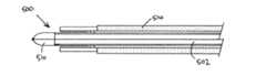
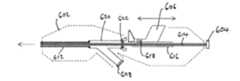
上述の二重機能を実現するために、本発明の電気手術機器は、2つの構成の間で調整可能なプローブ先端を備える。プローブ先端は、発生器からラジオ波(RF)および/またはマイクロ波周波数エネルギーを受信するように接続され、またガスのための流路を画定する。第1の構成では、プローブ先端は、バイポーラ(例えば、同軸)構造を画定して、ガスのための流路を横切るように、受信したRFおよび/またはマイクロ波周波数エネルギーから高電場を生成してプラズマを生成し維持する。第2の構成では、プローブ先端は、アンテナ構造を画定して、非電離マイクロ波エネルギーを組織内に放出する。アンテナ構造は、放射モノポールアンテナであってもよく、放射モノポールアンテナは、受信したマイクロ波周波数エネルギーからの電場を外向きに(すなわち、プローブから離れるように)放出可能な、円筒、ボール、針金またはヘリカルもしくはターンスタイルアンテナの形態を取ってもよい。よって、第1の構成では、機器は、RFエネルギーおよびマイクロ波エネルギーの一方または両方を使用してもよいが、第2の構成では、機器は、マイクロ波エネルギーを使用することが好ましい。 To achieve the dual function described above, the electrosurgical instruments of the present invention include probe tips that are adjustable between the two configurations. The probe tip is connected to receive radio frequency (RF) and / or microwave frequency energy from the generator and also defines a flow path for the gas. In the first configuration, the probe tip defines a bipolar (eg, coaxial) structure to generate a high electric field from the received RF and / or microwave frequency energy so as to cross the flow path for the gas. Generate and maintain plasma. In the second configuration, the probe tip defines the antenna structure and emits non-ionizing microwave energy into the tissue. The antenna structure may be a radiating monopole antenna, which is a cylinder, ball, capable of emitting an electric field from the received microwave frequency energy outward (ie, away from the probe). It may take the form of a wire or helical or turn-style antenna. Thus, in the first configuration, the device may use one or both of RF energy and microwave energy, but in the second configuration, the device preferably uses microwave energy.
バイポーラ構造は、内側導体と外側導体とを備えてもよい。外側導体は、プローブ先端を第1の構成および第2の構成の間で調整するために、内側導体に対して伸縮自在であってもよい。例えば、内側導体および外側導体が同軸に配置される場合、外側導体は、内側導体を取り囲む第1の位置(第1の構成に対応)から軸方向に後方へ(すなわち、機器の近位端部に向けて)変位した第2の位置(第2の構成に対応)まで収縮させて、内側導体を露出させてもよい。 The bipolar structure may include an inner conductor and an outer conductor. The outer conductor may be stretchable with respect to the inner conductor in order to adjust the probe tip between the first and second configurations. For example, if the inner and outer conductors are arranged coaxially, the outer conductor is axially rearward (ie, the proximal end of the device) from a first position (corresponding to the first configuration) surrounding the inner conductor. The inner conductor may be exposed by shrinking to a second position (corresponding to the second configuration) displaced (towards).
第1の構成では、RFまたはマイクロ波エネルギーを用いてプラズマを発生させてもよい。プラズマ発生後、マイクロ波エネルギーを使用してプラズマを維持してもよい。この構成は、ケーブルの容量および組織の多様性によって生じる負荷に起因して電場が崩壊することがある従来型の電気手術システムで使用されるRFプラズマよりも有利であり得る。 In the first configuration, RF or microwave energy may be used to generate the plasma. After the plasma is generated, microwave energy may be used to maintain the plasma. This configuration may be advantageous over RF plasmas used in conventional electrosurgery systems where the electric field can collapse due to loads caused by cable capacitance and tissue diversity.
プラズマのインピーダンスは、マイクロ波エネルギーの周波数でアプリケータ(およびエネルギー送達システム)のインピーダンスに整合させて、マイクロ波源で生成されたマイクロ波エネルギーを効率的にプラズマへと伝達できるようにすることが好ましい。マイクロ波エネルギーを使用する場合、アプリケータおよび/または発生器を(静的または動的に)調整して、プラズマを、組織が呈する負荷に確実に整合させるようにしてもよい。マイクロ波周波数では、ケーブルは、分布定数素子伝送線路を形成し、ここでは、アプリケータおよびエネルギー源の間のインピーダンス整合は、マイクロ波発生器のソースインピーダンス、ケーブル(伝送線路)の特性インピーダンス、アプリケータ構造自体のインピーダンス、および組織のインピーダンスによって決まる。ケーブルの特性インピーダンスがマイクロ波源の出力インピーダンスと同じ場合、ケーブルによる減衰(誘電損失および導体損失)を差し引いた、すべてのマイクロ波出力がアプリケータへと送達される。アプリケータおよび組織のインピーダンスがケーブルの特性インピーダンスと同じ場合、マイクロ波源で利用可能な最大出力がプラズマ/組織負荷へと伝達される。アプリケータおよびプラズマ/組織負荷の間で最も良いインピーダンス整合を維持するために、後述のように、アプリケータ構造を調整してもよい。また、発生器または第1のケーブルの遠位端部および第2の(器具)ケーブルの近位端部の間のインターフェースで調整してもよい。これらの調整は、整合ネットワークの容量および/またはインダクタンスの変化の形態、すなわち、スタブチューニングの形態であってもよい。 The impedance of the plasma is preferably matched to the impedance of the applicator (and energy delivery system) at the frequency of the microwave energy so that the microwave energy generated by the microwave source can be efficiently transferred to the plasma. .. When using microwave energy, the applicator and / or generator may be adjusted (statically or dynamically) to ensure that the plasma is aligned with the load exerted by the tissue. At microwave frequencies, the cable forms a distributed constant element transmission line, where impedance matching between the applicator and energy source is the source impedance of the microwave generator, the characteristic impedance of the cable (transmission line), the application. It depends on the impedance of the structure itself and the impedance of the structure. If the characteristic impedance of the cable is the same as the output impedance of the microwave source, then all microwave output, minus cable attenuation (dielectric loss and conductor loss), is delivered to the applicator. If the impedance of the applicator and tissue is the same as the characteristic impedance of the cable, the maximum output available at the microwave source is transferred to the plasma / tissue load. The applicator structure may be adjusted as described below to maintain the best impedance matching between the applicator and the plasma / tissue load. It may also be adjusted at the interface between the generator or the distal end of the first cable and the proximal end of the second (instrument) cable. These adjustments may be in the form of changes in the capacitance and / or inductance of the matched network, i.e., in the form of stub tuning.
本明細書では、「マイクロ波周波数」は、広く400MHz〜100GHzの周波数範囲を指すこともあるが、1GHz〜60GHzの範囲であることが好ましい。検討している具体的な周波数は、915MHz、2.45GHz、3.3GHz、5.8GHz、10GHz、14.5GHzおよび24GHzである。対照的に、本明細書では、「ラジオ波」または「RF」は、少なくとも3桁小さい、例えば、最大300MHz、好適には10kHz〜1MHzの周波数範囲を指すために使用している。 As used herein, the "microwave frequency" may broadly refer to a frequency range of 400 MHz to 100 GHz, but is preferably in the range of 1 GHz to 60 GHz. The specific frequencies under consideration are 915 MHz, 2.45 GHz, 3.3 GHz, 5.8 GHz, 10 GHz, 14.5 GHz and 24 GHz. In contrast, "radio waves" or "RF" are used herein to refer to a frequency range that is at least three orders of magnitude smaller, eg, up to 300 MHz, preferably 10 kHz to 1 MHz.
本発明の一実施態様によれば、電気手術器具であって、ラジオ波(RF)および/またはマイクロ波周波数電磁(EM)エネルギーを伝えるための同軸ケーブル、ならびにRFおよび/またはマイクロ波エネルギーを受信するために同軸ケーブルの遠位端部に接続されるプローブ先端を備える細長いプローブと、細長いプローブを通してプローブ先端までガスを運ぶためのガス通路とを備え、同軸ケーブルが、内側導体、外側導体および内側導体を外側導体と隔てる誘電材料を備え、プローブ先端が、同軸ケーブルの内側導体に接続される第1の電極および同軸ケーブルの外側導体に接続される第2の電極を備え、第1の電極および第2の電極が、熱または非熱プラズマを生成するために、ガス通路から受け入れたガスの流路を横切るように、受信したRFおよび/またはマイクロ波周波数EMエネルギーから電場を生成するように構成される第1の構成と、第1の電極が第2の電極を越えて遠位に延びてプローブ先端から外向きにマイクロ波EM場を放出するための放射構造を形成する第2の構成との間で互いに対して移動可能である、電気手術器具が提供される。よって、第1の構成では、器具は、生体組織の表面(または表層)の凝固および/または生体組織もしくは各種器具の滅菌/消毒に好適なプラズマを生成するように動作するのであってもよい。ガスは、アルゴン、または任意の他の好適なガスであってよく、例えば、二酸化炭素、ヘリウム、窒素、空気およびこれらのガスのうちの任意のガスの混合物、すなわち、空気10%/ヘリウム90%であってもよい。プローブ先端でRF EMエネルギーまたはマイクロ波EMエネルギーのいずれかに対して高インピーダンス状態を作ることによって、プラズマを発生させるための高電場を生じさせてもよい。このことは、第1および第2の電極の好適な幾何形状を選択することにより達成され得る。例えば、第1の構成において第1および第2の電極の間に石英または他の類似の低損失材料などの、一片の絶縁誘電材料を配置してもよい。このことがインピーダンスを高め、したがって高電場の生成を促進することもある。第1の構成では、第1の導体を越えて(例えば、第1の導体よりも遠位に)第2の電極を延びるように構成させて、非電離放射が絶対に放出されないようにしてもよい。 According to one embodiment of the invention, an electrosurgical instrument that receives a coaxial cable for transmitting radio wave (RF) and / or microwave frequency electromagnetic (EM) energy, and RF and / or microwave energy. The coaxial cable comprises an elongated probe with a probe tip connected to the distal end of the coaxial cable to carry gas through the elongated probe to the probe tip, and the coaxial cable has an inner conductor, an outer conductor and an inner conductor. It comprises a dielectric material that separates the conductor from the outer conductor, and the probe tip comprises a first electrode connected to the inner conductor of the coaxial cable and a second electrode connected to the outer conductor of the coaxial cable, the first electrode and The second electrode is configured to generate an electric field from the received RF and / or microwave frequency EM energy so as to cross the flow path of the gas received from the gas passage to generate a thermal or non-thermal plasma. A first configuration to be formed and a second configuration in which the first electrode extends distally beyond the second electrode to form a radiation structure for emitting a microwave EM field outward from the probe tip. Electrosurgical instruments are provided that are movable relative to each other. Thus, in the first configuration, the instrument may operate to coagulate the surface (or surface layer) of the living tissue and / or generate plasma suitable for sterilizing / disinfecting the living tissue or various instruments. The gas may be argon, or any other suitable gas, eg, carbon dioxide, helium, nitrogen, air and a mixture of any of these gases, i.e. 10% air / 90% helium. It may be. A high electric field may be created to generate the plasma by creating a high impedance state at the probe tip for either RF EM energy or microwave EM energy. This can be achieved by choosing suitable geometry for the first and second electrodes. For example, in the first configuration, a piece of insulating dielectric material, such as quartz or other similar low loss material, may be placed between the first and second electrodes. This increases impedance and thus may facilitate the generation of high electric fields. In the first configuration, the second electrode is configured to extend beyond the first conductor (eg, distal to the first conductor) so that non-ionizing radiation is never emitted. Good.
第2の構成では、プローブは、生体組織の深部凝固または滅菌のためのマイクロ波EM場の形態で、マイクロ波周波数エネルギーを放射することができる。 In the second configuration, the probe can radiate microwave frequency energy in the form of a microwave EM field for deep coagulation or sterilization of living tissue.
好適な実施形態では、器具は、RFおよびマイクロ波EMエネルギーの両方を受信可能である。RFEMエネルギーは、プラズマ発生のためであってもよく、高電圧パルスとして受信されてもよい。マイクロ波EMエネルギーは、プラズマを維持するためのもの、すなわち、プラズマへと出力を送達して電離状態を維持するためのものである。これもまた、パルスとして受信してもよい。プラズマの準連続ビームを生成する方法で、プラズマを繰り返し発生させてもよい。この構成がRF EMエネルギーのみを使用する従来型のAPC機器よりも有利である点は、容量性負荷または乾燥から湿潤への環境変化に起因してプラズマが崩壊しない点である。さらに、器具の二重構成の性質により、器具は、深部凝固に好適な状態に切り替わることができ、この状態において、第2の電極(および絶縁誘電材料)は、後述のように、第1の電極が放射マイクロ波モノポールアンテナ構造として働くように第1の電極を露出させる離れた所に引き離される。 In a preferred embodiment, the instrument is capable of receiving both RF and microwave EM energy. RFEM energy may be due to plasma generation or may be received as a high voltage pulse. The microwave EM energy is for maintaining the plasma, that is, for delivering the output to the plasma and maintaining the ionized state. This may also be received as a pulse. Plasma may be repeatedly generated by a method of generating a quasi-continuous beam of plasma. The advantage of this configuration over conventional APC equipment that uses only RF EM energy is that the plasma does not collapse due to capacitive loading or environmental changes from dry to wet. Further, due to the dual nature of the instrument, the instrument can be switched to a state suitable for deep solidification, in which the second electrode (and insulating dielectric material) is the first, as described below. The electrodes are pulled apart to expose the first electrode so that it acts as a radiated microwave monopole antenna structure.
また、マイクロ波周波数エネルギーを使用して、例えば、マイクロ波共振器、または動作周波数で四分の一波長(またはその奇数倍)の長さの、より高インピーダンスの伝送線路を使用してプラズマを発生するために低い電圧をより高い電圧に変換するインピーダンス変成器、すなわち、四分の一波長変成器を使用することによって、プラズマを発生させることが可能であってもよい。この高インピーダンス線路を切り替えて接続してプラズマを発生させてもよいし、プラズマが発生してプラズマを維持する必要がある場合切り替えて切り離して(すなわち、より低インピーダンスの線路に戻す)もよい。2つの状態の間で切り替えるために、パワーPINまたはバラクタダイオードを使用することが好ましいこともあるが、同軸または導波管スイッチを使用することもできる。 It also uses microwave frequency energy to generate plasma, for example, using a microwave resonator, or a higher impedance transmission line that is a quarter wavelength (or an odd multiple of it) at the operating frequency. It may be possible to generate the plasma by using an impedance modifier that converts the lower voltage to a higher voltage to generate, i.e., a quarter wavelength transformer. The high impedance lines may be switched and connected to generate plasma, or may be switched and disconnected (ie, returned to a lower impedance line) when plasma is generated and the plasma needs to be maintained. It may be preferable to use a power PIN or varicap diode to switch between the two states, but coaxial or waveguide switches can also be used.
細長いプローブは、同軸ケーブルを取り囲むスリーブを備えてもよい。スリーブは、同軸ケーブルを保護するように働くのであってもよいが、また、例えば、スリーブの内面および同軸ケーブルの外面の間の空間としてガス通路を画定してもよい。ガス通路は、ガス源(例えば、加圧ガスキャニスタなど)に接続するためにスリーブの近位端部に入力ポートを有してもよい。 The elongated probe may include a sleeve that surrounds the coaxial cable. The sleeve may act to protect the coaxial cable, but may also define the gas passage as a space between, for example, the inner surface of the sleeve and the outer surface of the coaxial cable. The gas passage may have an input port at the proximal end of the sleeve to connect to a gas source (eg, a pressurized gas canister, etc.).
さらに、スリーブは、第1および第2の電極を相対的に動かすための手段であってもよい。マイクロ波同軸ケーブル上で導電性(例えば、金属製)カテーテルを摺動させることによって、第1および第2の電極を相対的に動かしてもよく、マイクロ波同軸ケーブルの外側導体もまた金属製であってもよい。この構成では、カテーテル(または同軸ケーブル上で摺動するチューブ)の内面は、同軸ケーブルの外側導体と良好に電気接触していなければならない。このことは、第2の電極または同軸ケーブルの外側電極に対して摺動可能であり、かつガスを流すことができるガス透過性導電構造を提供することによって達成されてもよい。ガス透過性導電構造は、導電性メッシュ、放射状に延びる導電性ワイヤまたはばね、および複数の周縁方向に離間した放射状に突出する歯(dents)のうちのいずれであってもよい。よって、ガス透過性導電構造は、複数の(例えば、4つ以上)周方向接続部を提供してもよく、そうでなければマイクロ波信号のための良好な電気接続を確実にするための点接点を設ける必要がある。この解決策により、マイクロ波エネルギーが伝播するのに適切な環境を作るのに十分な接続点を有すること、十分なガスが流れるようにすること、および外側カテーテルが同軸ケーブルの上で比較的容易に動くことができるようにすることの間でバランスを取ることもできる。 Further, the sleeve may be a means for relatively moving the first and second electrodes. The first and second electrodes may be moved relative to each other by sliding a conductive (eg, metal) catheter over the microwave coaxial cable, and the outer conductor of the microwave coaxial cable is also made of metal. There may be. In this configuration, the inner surface of the catheter (or tube that slides on the coaxial cable) must be in good electrical contact with the outer conductor of the coaxial cable. This may be achieved by providing a gas permeable conductive structure that is slidable with respect to the second electrode or the outer electrode of the coaxial cable and allows gas to flow. The gas permeable conductive structure may be any of a conductive mesh, radially extending conductive wires or springs, and a plurality of radially spaced radially protruding teeth (dents). Thus, the gas permeable conductive structure may provide multiple (eg, 4 or more) circumferential connections, otherwise to ensure good electrical connections for microwave signals. It is necessary to provide contacts. This solution allows for sufficient connection points to create a suitable environment for microwave energy to propagate, allows sufficient gas to flow, and makes the outer catheter relatively easy on coaxial cable. You can also balance between being able to move in.
一実施形態では、スリーブの遠位端部に第2の電極を設ける、または形成してもよく、またスリーブは、同軸ケーブルに対して伸縮可能であってもよい。換言すると、スリーブは、第1の電極をプローブ先端で露出させるように引き下げることが可能であってもよい。スリーブは、同軸ケーブルと同軸であってもよい。よって、第1および第2の電極は、第1の構成では互いに同軸であってもよい。第2の電極は、スリーブの遠位端部上にある導電性材料の環状帯であってもよい。上述の誘電材料は、スリーブ上かつ環状帯の内側に設けられた石英製カラーであってもよい。代替的または追加的に、誘電材料は、後述のように、内側電極の一部であってもよい。 In one embodiment, a second electrode may be provided or formed at the distal end of the sleeve, and the sleeve may be stretchable with respect to the coaxial cable. In other words, the sleeve may be capable of pulling down so that the first electrode is exposed at the probe tip. The sleeve may be coaxial with the coaxial cable. Therefore, the first and second electrodes may be coaxial with each other in the first configuration. The second electrode may be an annular band of conductive material over the distal end of the sleeve. The dielectric material described above may be a quartz collar provided on the sleeve and inside the annular band. Alternatively or additionally, the dielectric material may be part of the inner electrode, as described below.
伸縮自在なスリーブは、2つ以上の伸縮自在部分を備えてもよい。伸縮自在部分は、その間に液密封止部を有してガスが漏れないようにしてもよい。機械または電気機械システム、すなわち、機械式スライダ、リニアモータまたはステッピングモータ構成を用いて、摺動可能な外側スリーブを収縮または伸長させてもよい。後述するように、同軸ケーブルの外側導体に対する外側スリーブの位置は、発生器内またはプローブ内の検出器(複数可)を使用し、反射電力または順方向および反射電力測定、すなわち、反射計またはVSWRブリッジ測定を使用してなされる反射損失またはインピーダンス整合/不整合測定によって決定してもよい。 The stretchable sleeve may include two or more stretchable portions. The stretchable portion may have a liquidtight sealing portion between them to prevent gas from leaking. A mechanical or electromechanical system, ie, a mechanical slider, linear motor or stepper motor configuration, may be used to retract or extend the slidable outer sleeve. As will be described later, the position of the outer sleeve with respect to the outer conductor of the coaxial cable uses a detector (s) in the generator or probe to measure reflected power or forward and reflected power, ie, a reflector or VSWR. It may be determined by reflection loss or impedance matching / mismatching measurements made using bridge measurements.
代替的な実施形態では、同軸ケーブル自体をスリーブ内で動かすことができてもよい。この構成では、手動スライダまたは本明細書で言及する同軸ケーブルをスリーブ内で摺動させるための移動機構のいずれかを含み得る、近位にあるハンドピースにスリーブを固定してもよい。 In an alternative embodiment, the coaxial cable itself may be movable within the sleeve. In this configuration, the sleeve may be secured to a proximal handpiece, which may include either a manual slider or a moving mechanism for sliding the coaxial cable referred to herein within the sleeve.
第1の電極は、同軸ケーブルからRFおよび/またはマイクロ波EMエネルギーを受信するように連結された、マイクロ波放射モノポールアンテナ構造であってもよい。同軸ケーブルの外側導体は、アンテナに不平衡給電を形成するように接地してもよいし、あるいはアンテナに平衡給電を形成する、すなわち、両導体にかかる電圧が上下するように浮かせてもよい。第1の電極は、受信したマイクロ波EM放射に対応するマイクロ波場を放出するためのマイクロ波アンテナとして働くような形にされることが好ましい。例えば、モノポーラ放射構造は、円筒形の誘電材料を備えてもよく、これは、半球状の遠位端部を有し、かつ外側導体を越えて突出し円筒形の誘電材を通って延びてその半球状の遠位端部で突出する同軸ケーブルの内側導体の長さを取り囲む。他の遠位端部の形状、例えば、ボールまたは平坦端部も可能である。円筒は、低損失セラミック材料から作られてもよい。誘電体円筒の存在により、例えば、反射電力量を減らすことによって、組織内へのエネルギー送達を改善することができる。円筒の半球状の遠位端部から突出する内側導体の長さの端部に丸みをつけて、例えば、半球状にして、放射される場をより均一にしてもよい。 The first electrode may be of a microwave emitting monopole antenna structure connected to receive RF and / or microwave EM energy from a coaxial cable. The outer conductors of the coaxial cable may be grounded to form an unbalanced feed on the antenna, or they may form a balanced feed on the antenna, i.e., float the voltages across the conductors up and down. The first electrode is preferably shaped to act as a microwave antenna for emitting a microwave field corresponding to the received microwave EM radiation. For example, the monopolar radiating structure may comprise a cylindrical dielectric material, which has a hemispherical distal end and extends beyond the outer conductor and extends through the cylindrical dielectric material. Surrounds the length of the inner conductor of the coaxial cable protruding at the distal end of the hemisphere. Other distal end shapes, such as balls or flat ends, are also possible. The cylinder may be made of a low loss ceramic material. The presence of the dielectric cylinder can improve energy delivery into the tissue, for example by reducing the amount of reflected power. The end of the length of the inner conductor protruding from the distal end of the hemispherical shape of the cylinder may be rounded, for example, hemispherically to make the radiated field more uniform.
制御下で凝固させるために血液内に効率的に照射させる非電離放射を生成するために、モノポーラ放射構造(すなわち、第2の構成にある第1の電極)を、マイクロ波EM放射の周波数において血液のインピーダンスに十分に整合するように構成することが好ましい。 To generate non-ionizing radiation that efficiently irradiates the blood for coagulation under control, a monopolar radiation structure (ie, the first electrode in the second configuration) is applied at the frequency of microwave EM radiation. It is preferably configured to be well matched to the blood impedance.
同軸ケーブルの外側電極を、ガスを通過させる導電メッシュによって第2の電極に接続してもよい。したがって、導電メッシュを、プローブ内の通路、すなわち、同軸ケーブルおよびスリーブの間の空間に設けてもよい。あるいは、同軸ケーブルおよびスリーブの間の空間を、例えば、スリーブまたはスリーブの一部に接続された分割要素によって、複数のサブ通路に分割してもよい。この場合、分割要素または別個のコネクタ要素が、同軸ケーブルの外側導体および第2の電極の間を電気接続させてもよい。接続はまた、1つの可撓性ワイヤまたは条片から作られてもよく、これを第2の電極にはんだ付けまたは圧着させてもよい。 The outer electrode of the coaxial cable may be connected to the second electrode by a conductive mesh that allows gas to pass through. Therefore, the conductive mesh may be provided in the passage within the probe, i.e., in the space between the coaxial cable and the sleeve. Alternatively, the space between the coaxial cable and the sleeve may be divided into a plurality of sub-passages, for example, by a sleeve or a dividing element connected to a part of the sleeve. In this case, a split element or a separate connector element may make an electrical connection between the outer conductor of the coaxial cable and the second electrode. The connection may also be made from a single flexible wire or strip, which may be soldered or crimped to a second electrode.
プローブは、腹腔鏡下で使用してもよいし、あるいは内視鏡検査機器を通して、例えば、内視鏡、胃鏡、気管支鏡などの処置具用チャンネルを通して挿入可能な寸法にされてもよい。例えば、同軸ケーブルは、2.5mm未満の直径を有してもよく、2.2mm未満であることが好ましい。スリーブは、2.6mm未満の外側直径を有してもよく、2.5mm未満であることが好ましい。より大型の腹腔鏡器具では、外側直径は3mm以上であってもよく、より大きい直径の同軸ケーブルを使用してもよい。 The probe may be used under a laparoscope or may be sized so that it can be inserted through an endoscopy instrument, for example, through a treatment instrument channel such as an endoscope, gastroscope, or bronchoscope. For example, the coaxial cable may have a diameter of less than 2.5 mm, preferably less than 2.2 mm. The sleeve may have an outer diameter of less than 2.6 mm, preferably less than 2.5 mm. For larger laparoscopic instruments, the outer diameter may be 3 mm or more, and coaxial cables with larger diameters may be used.
本発明の別の実施態様によれば、凝固を行うための電気手術装置であって、マイクロ波EMエネルギーを発生するためのマイクロ波信号発生器と、マイクロ波EMエネルギーを受信するように接続される上述の電気手術器具と、プローブにマイクロ波EMエネルギーを伝えるための供給構造であって、供給構造が、プローブをマイクロ波信号発生器に接続するためのマイクロ波チャンネルを備える、供給構造と、電気手術器具にガスを供給するように接続されるガス供給部とを備え、装置が、電気手術器具が第1の構成にあり、そこにガスが供給される場合、表面凝固モードで動作可能であり、それによって、プローブ先端に送達されるマイクロ波EMエネルギーが第1および第2の電極の間でガスプラズマを発生および/または維持するように構成され、電気手術器具が第2の構成にあり、そこにガスの供給がない場合、深部組織凝固モードで動作可能であり、それによって、プローブ先端に送達されるマイクロ波EMエネルギーがプローブ先端から外向きに非電離電場を出すように構成される、電気手術装置が提供される。装置は、第1の周波数を有するRF電磁(EM)エネルギーを発生するためのラジオ波(RF)信号発生器を含んでもよく、マイクロ波周波数EMエネルギーは、第1の周波数よりも高い第2の周波数を有し、供給構造が、プローブをRF信号発生器に接続するためのRFチャンネルを含み、表面凝固モードでは、装置が、RF EMエネルギーをプローブ先端に送達して第1および第2の電極の間でガスプラズマを発生するように構成される。 According to another embodiment of the present invention, an electrosurgical apparatus for performing coagulation, which is connected to a microwave signal generator for generating microwave EM energy so as to receive microwave EM energy. The above-mentioned electrosurgical instruments and a supply structure for transmitting microwave EM energy to the probe, wherein the supply structure includes a microwave channel for connecting the probe to the microwave signal generator. It has a gas supply that is connected to supply gas to the electrosurgical instrument, and the device can operate in surface coagulation mode when the electrosurgical instrument is in the first configuration and gas is supplied to it. Yes, thereby the microwave EM energy delivered to the probe tip is configured to generate and / or maintain a gas plasma between the first and second electrodes, and the electrosurgical instrument is in the second configuration. , When there is no gas supply, it can operate in deep tissue coagulation mode, which is configured so that the microwave EM energy delivered to the probe tip creates a non-ionized field outward from the probe tip. , Electrosurgical equipment is provided. The device may include a radio frequency (RF) signal generator to generate radio frequency (EM) energy having a first frequency, the radio frequency EM energy being a second frequency higher than the first frequency. Having a frequency, the feed structure includes an RF channel for connecting the probe to the RF signal generator, and in surface coagulation mode, the device delivers RF EM energy to the probe tip to the first and second electrodes. It is configured to generate gas plasma between the frequencies.
装置は、RF EM放射のパルス(または複数のパルス)をプローブに送達させて、プラズマを発生させるために流路を横断して高電場を発生させるように構成されるプラズマ発生信号発生回路を備えてもよく、プラズマ発生信号発生回路は、マイクロ波チャンネル上のマイクロ波EM放射のパルスの検出可能な特性を使用して、RF EM放射のパルスの発生を開始させるように構成される制御回路を含む。このように、RF EM放射は、プラズマを発生させるために使用されるが、マイクロ波EM放射は、プラズマを維持するために使用される。上述のようにマイクロ波EM放射のパルスに対してRF発生パルスの送達を調整することによって、装置は、より確実にプラズマを発生させることができる。 The device comprises a plasma generation signal generation circuit configured to deliver a pulse (or multiple pulses) of RF EM radiation to the probe to generate a high electric field across the flow path to generate plasma. The plasma generation signal generation circuit may be a control circuit configured to initiate the generation of RF EM radiation pulses using the detectable properties of microwave EM radiation pulses on the microwave channel. Including. Thus, RF EM radiation is used to generate the plasma, while microwave EM radiation is used to maintain the plasma. By adjusting the delivery of the RF generation pulse to the pulse of microwave EM radiation as described above, the device can more reliably generate the plasma.
装置は、マイクロ波チャンネル上の順方向および反射電力をサンプリングし、かつそこから、プローブによってマイクロ波出力が送達されたことを示すマイクロ波検出信号を生成するためのマイクロ波信号検出器と、マイクロ波検出信号を受信するためのマイクロ波信号検出器と通信可能なコントローラとをさらに備えてもよく、コントローラが、マイクロ波EM放射のためのエネルギー送達プロファイルを選択するように動作可能であり、マイクロ波EM放射ためのエネルギー送達プロファイルが組織の凝固のためのものであり、コントローラが、マイクロ波信号発生器のためのマイクロ波制御信号を出力するようにプログラムされたデジタルマイクロプロセッサを備え、マイクロ波制御信号が、マイクロ波EM放射のためのエネルギー送達プロファイルを設定するためのものであり、コントローラが、受信したマイクロ波検出信号に基づいてマイクロ波制御信号の状態を判定するように構成される。この構成を使用して、反射マイクロ波信号を測定し、それによって、マイクロ波検出信号は、プラズマが発生したか否かの指標にしてもよい。信号検出器はまた、順方向および反射マイクロ波EM放射を連続的に監視するように構成させて、プラズマを送達する間に最適なインピーダンス整合が確実に維持されるようにしてもよい。マイクロ波信号検出器は、順方向および反射信号検出器(例えば、マイクロ波チャンネル上に好適な方向性パワーカプラ)を備えてもよい。検出器は、信号強度のみを検出するように構成されてもよく、例えば、これらは、ダイオード検出器であってもよい。あるいは、検出器は、強度および位相を検出するように構成されてもよく、例えば、これらは、ヘテロダイン検出器であってもよい。よって、マイクロ波検出信号は、反射損失またはインピーダンス整合情報を表すのであってもよい。電気手術器具の第1および第2の電極の相対位置は、表面凝固モード(すなわち、プラズマが発生されている場合)では、設定された反射損失閾値、すなわち、8dB、10dBまたは12dBに到達するまでコントローラによって調整可能であってもよい。 The device samples the forward and reflected power on the microwave channel, from which the microwave signal detector and the microwave are used to generate a microwave detection signal indicating that the probe has delivered the microwave output. It may further include a microwave signal detector for receiving the wave detection signal and a communicable controller, the controller being able to operate to select an energy delivery profile for microwave EM radiation, micro. The energy delivery profile for wave EM emission is for tissue coagulation, and the controller is equipped with a digital microprocessor programmed to output microwave control signals for the microwave signal generator, microwave. The control signal is for setting an energy delivery profile for microwave EM radiation, and the controller is configured to determine the state of the microwave control signal based on the received microwave detection signal. This configuration may be used to measure the reflected microwave signal, whereby the microwave detection signal may be an indicator of whether or not plasma has been generated. The signal detector may also be configured to continuously monitor forward and reflected microwave EM radiation to ensure optimal impedance matching is maintained during plasma delivery. The microwave signal detector may include forward and reflected signal detectors (eg, directional power couplers suitable for microwave channels). The detectors may be configured to detect only the signal strength, for example they may be diode detectors. Alternatively, the detectors may be configured to detect intensity and phase, for example, they may be heterodyne detectors. Therefore, the microwave detection signal may represent reflection loss or impedance matching information. The relative positions of the first and second electrodes of the electrosurgical instrument, in surface coagulation mode (ie, when plasma is being generated), reach the set return loss threshold, ie 8 dB, 10 dB or 12 dB. It may be adjustable by the controller.
装置は、第1の電極と第2の電極とを相対的に動かすための移動機構を含んでもよく、コントローラが、受信したマイクロ波検出信号に基づいて移動機構に制御信号を伝えるように構成される。移動機構は、機械式であってもよく、例えば、器具の操作者によって手動で制御されてもよい。移動機構は、器具の遠位端部、例えば、手動の摺動または回転機構に配置されるアクチュエータ、例えば、レバーまたはプルアームを備えてもよい。 The device may include a moving mechanism for moving the first electrode and the second electrode relative to each other, and the controller is configured to transmit a control signal to the moving mechanism based on the received microwave detection signal. To. The moving mechanism may be mechanical or may be manually controlled, for example, by the operator of the instrument. The moving mechanism may include an actuator, such as a lever or pull arm, that is located at the distal end of the instrument, eg, a manual sliding or rotating mechanism.
しかしながら、例えば、電気機械的機構を用いて、第1および第2の電極の相対運動(すなわち、第1および第2の構成の設定)を自動で制御することもまた本明細書において企図されている。例えば、一実施形態では、スリーブを自動的に動かし、治療部位の血流量に応じてガス供給を作動させるように構成される設定コントローラがあってもよい。この特徴を利用して、大量出血の応急処置、および健常な組織が加熱される深さの抑制を確実にしてもよい。 However, it is also contemplated herein to automatically control the relative motion of the first and second electrodes (ie, the setting of the first and second configurations), for example using an electromechanical mechanism. There is. For example, in one embodiment, there may be a configuration controller configured to automatically move the sleeve and activate the gas supply according to the blood flow at the treatment site. This feature may be used to ensure first aid for massive bleeding and control of the heating depth of healthy tissue.
さらに、コントローラは、プラズマへのインピーダンス整合を制御するための手段として移動機構を自動的に操作するように構成されてもよい。マイクロ波チャンネル上の反射および順方向電力測定を使用して、手動によって、または反射損失測定またはインピーダンス整合に基づいて電気機械的アクチュエータ(PZTアクチュエータ、磁歪アクチュエータ、ステッピングモータ、リニアモータ)を利用して、内側同軸ケーブル(または同軸ケーブルに取り付けられた内側電極)に対する外側カテーテルの位置を制御してもよい。ABCまたは表面凝固の最中に深部または大量の出血が生じることにより、プラズマが消失し、その結果、反射損失測定値が変化することもある、すなわち、10dB(良好な整合)から2dB(劣悪な整合)に変化することもある。本発明では、外側スリーブが自動的に後退することにより、マイクロ波アンテナを展開させて、電離ガス(プラズマ)ではなく大きい出血部に対応するための深部凝固を行う非電離マイクロ波エネルギーを血液または血管に導入可能にしてもよい。 In addition, the controller may be configured to automatically operate the moving mechanism as a means of controlling impedance matching to the plasma. Utilizing electromechanical actuators (PZT actuators, magnetic strain actuators, stepping motors, linear motors) manually or based on reflection loss measurement or impedance matching using reflection and forward power measurements on microwave channels. , The position of the outer catheter with respect to the inner coaxial cable (or the inner electrode attached to the coaxial cable) may be controlled. Deep or massive bleeding during ABC or surface coagulation can result in plasma disappearance, which can result in changes in return loss measurements, ie from 10 dB (good match) to 2 dB (poor match). It may change to (consistency). In the present invention, the outer sleeve automatically retracts to deploy a microwave antenna to provide blood or non-ionized microwave energy for deep coagulation to accommodate large bleeding areas rather than ionized gas (plasma). It may be able to be introduced into a blood vessel.
設定コントローラは、第1および第2の電極を互いに相対的に動かすために、スリーブまたは同軸ケーブルに接続されるステッピングモータまたはリニアモータを含んでもよい。第1の電極の移動はまた、インピーダンス整合または反射損失測定のかわりに、あるいはこれだけではなく、流量測定に基づいてもよい。この例では、動作モードは、表面凝固(ABC)から深部凝固(非電離マイクロ波放射を送達するためにモノポールアンテナを延長)まで自動的に変わって、血流量の増加に基づいて深部凝固を行う。 The configuration controller may include a stepper motor or linear motor connected to a sleeve or coaxial cable to move the first and second electrodes relative to each other. The movement of the first electrode may also be based on flow rate measurement instead of, or not limited to, impedance matching or return loss measurement. In this example, the mode of operation automatically changes from surface coagulation (ABC) to deep coagulation (extending a monopole antenna to deliver non-ionizing microwave radiation), with deep coagulation based on increased blood flow. Do.
設定コントローラをバルブに接続して、例えば、器具が第2の構成に移動した場合に供給を遮断し、器具が第1の構成に移動した場合に供給を開始するようにガス供給を制御してもよい。バルブは、器具の一部であってもよい、例えば、スリーブおよび同軸ケーブルの間に組み込まれてもよいし、器具の外側、例えば、ガス供給部に配置されてもよい。 A configuration controller is connected to the valve to control the gas supply so that, for example, the supply is cut off when the appliance moves to the second configuration and started when the appliance moves to the first configuration. May be good. The valve may be part of the appliance, eg, incorporated between the sleeve and coaxial cable, or may be located outside the appliance, eg, at the gas supply.
さらに、上述のマイクロ波信号検出器と組み合わせて、設定コントローラは、マイクロ波検出信号に基づいて反射マイクロ波信号を最小にするように、プラズマが存在する場合に第1の構成におけるスリーブの位置を制御するように構成されてもよい。換言すると、設定コントローラは、プラズマの効率的な送達を助けるために、第1の構成においてスリーブの位置を精密に調整するためのフィードバック構成を備える。 In addition, in combination with the microwave signal detector described above, the configuration controller position the sleeve in the first configuration in the presence of plasma so as to minimize the reflected microwave signal based on the microwave detection signal. It may be configured to control. In other words, the configuration controller includes a feedback configuration for precisely adjusting the position of the sleeve in the first configuration to aid in the efficient delivery of plasma.
第1の構成にある場合、熱プラズマを発生するように器具を構成してもよいが、滅菌のために非熱プラズマを発生するように構成してもよい。同軸アプリケータ構造が、3mm〜5mmの直径である、すなわち同軸構造内の外側導体の内径が3mm〜5mmの直径である、プラズマ発生領域と、0.25mm〜1mmの壁厚で内側にぴったり嵌まる石英チューブとを有し、内側導体の外径が0.75mm〜4mmの場合に(内側導体および石英チューブの内壁の間の領域にガスが流れる空間を設けることができる)、40%未満、すなわち、28%のデューティサイクルのパルスモードで発生器を動作させることによって、消毒または滅菌に好適な非熱プラズマを発生させることができる。一実施形態では、単一のマイクロ波パルスの出力の実効値は50Wであり、一周期140msのうち、パルスONの時間は40msである、すなわち、プラズマへと送達される平均出力は、2.45GHzで14.28Wである。RF発生パルスをこの構成で使用した場合、RF発生パルス幅は、約1msであり、正弦波振動の周波数は100kHzであった。振幅は、ピーク値で約1kV(707Vrms)であった。RF出力は、マイクロ波出力の10%未満であった。RFパルスは、マイクロ波バーストまたはパルスに同期させ、マイクロ波バーストまたはパルスの立ち上がりエッジにトリガをかけた。 In the case of the first configuration, the instrument may be configured to generate thermal plasma, but may be configured to generate non-thermal plasma for sterilization. The coaxial applicator structure fits snugly inward with a plasma generating region of 3 mm to 5 mm in diameter, i.e., the inner diameter of the outer conductor in the coaxial structure is 3 mm to 5 mm in diameter, and a wall thickness of 0.25 mm to 1 mm. Less than 40% when it has a whole quartz tube and the outer diameter of the inner conductor is 0.75 mm to 4 mm (a space can be provided for gas to flow in the region between the inner conductor and the inner wall of the quartz tube). That is, by operating the generator in pulse mode with a duty cycle of 28%, a non-thermal plasma suitable for disinfection or sterilization can be generated. In one embodiment, the effective value of the output of a single microwave pulse is 50 W, and the pulse ON time is 40 ms in 140 ms of one cycle, that is, the average output delivered to the plasma is 2. It is 14.28 W at 45 GHz. When the RF generated pulse was used in this configuration, the RF generated pulse width was about 1 ms and the frequency of the sinusoidal vibration was 100 kHz. The amplitude was about 1 kV (707 Vrms) at the peak value. The RF output was less than 10% of the microwave output. The RF pulse was synchronized with the microwave burst or pulse and triggered the rising edge of the microwave burst or pulse.
この特定のアプリケータ幾何形状については、熱プラズマを生成するために、デューティサイクルを増加、すなわち、50%まで増加させてもよく、あるいは、連続波(CW)および/または実行出力レベルを増加、すなわち、75Wまたは100Wまで増加させてもよい(幾何形状が減少または増加した場合、それに応じてマイクロ波出力およびRF発生パルスの振幅を調整する)。RFマイクロ波出力の割合は、非熱および熱プラズマでは一定、すなわち、10%未満に保つことが好ましい。 For this particular applicator geometry, the duty cycle may be increased, i.e. up to 50%, or continuous wave (CW) and / or execution output levels may be increased to generate thermal plasma. That is, it may be increased to 75 W or 100 W (when the geometry decreases or increases, the microwave output and the amplitude of the RF generated pulse are adjusted accordingly). The proportion of RF microwave output is preferably kept constant for non-thermal and thermal plasmas, i.e. less than 10%.
器具の遠位端部において滅菌を行う能力を有することは、スコープ類の器具チャンネルを消毒する目的には特に有利であり得る。換言すると、器具がスコープ(例えば、内視鏡など)から引き抜かれるにつれて非熱プラズマが放出されて器具の内面の処理を行う。この目的には非熱プラズマが好ましいが、非電離マイクロ波RF放射のみを送達することによって、すなわちガスなしで滅菌することも可能であり得る。 Having the ability to perform sterilization at the distal end of the instrument can be particularly advantageous for the purpose of disinfecting the instrument channel of scopes. In other words, as the instrument is pulled out of the scope (eg, an endoscope), non-thermal plasma is emitted to process the inner surface of the instrument. Non-thermal plasmas are preferred for this purpose, but it may also be possible to sterilize by delivering only non-ionizing microwave RF radiation, i.e. without gas.
非熱プラズマの滅菌機能を利用して治療前後に体腔を滅菌してもよい。器具、例えば、内視鏡または胃鏡を洗浄または滅菌するために機器を使用する場合、非熱プラズマおよび非電離マイクロ波放射の組み合わせを生成するように機器を構成してもよい。機器はまた、NOTES法で使用される場合、または表面凝固、身体組織の滅菌および大血管または大きい出血部の深部凝固を行うことが有利である場合、非熱プラズマ、熱プラズマおよび非電離マイクロ波放射を生成するように構成されてもよい。 The body cavity may be sterilized before and after treatment using the sterilization function of non-thermal plasma. When using an instrument to clean or sterilize an instrument, such as an endoscope or gastroscope, the instrument may be configured to produce a combination of non-thermal plasma and non-ionizing microwave radiation. The instrument is also used in the NOTES method, or when it is advantageous to perform surface coagulation, sterilization of body tissue and deep coagulation of large blood vessels or large bleeding areas, non-thermal plasma, thermal plasma and non-ionized microwaves. It may be configured to generate radiation.
よって、装置および器具は、4つの使用モードを有してもよい。すなわち:
−内視鏡もしく任意の他のスコープまたは他の機器の器具チャンネルの滅菌または消毒するために使用される、あるいは生体組織または体表面を滅菌または消毒するために使用される非熱プラズマ
−内視鏡、他のスコープまたは他の機器の器具チャンネルを滅菌または消毒するための非電離マイクロ波放射
−表面または表層凝固のための熱プラズマ
−深部凝固のための非電離マイクロ波放射。Thus, devices and appliances may have four modes of use. That is:
-Inside a non-thermal plasma used to sterilize or disinfect the instrument channel of an endoscope or any other scope or other device, or to sterilize or disinfect living tissue or body surface. Non-ionizing microwave radiation for sterilizing or disinfecting instrument channels of endoscopes, other scopes or other equipment-thermal plasma for surface or surface coagulation-non-ionizing microwave radiation for deep coagulation.
換言すると、器具のスリーブは、4つの状態の間で調整可能であってもよい。すなわち:
−非電離マイクロ波放射:モノポール放射アンテナが、深部凝固のための非電離マイクロ波放射を放出するために露出される;
−RFおよびマイクロ波エネルギーを使用するプラズマ発生:放射モノポールが外側スリーブによって覆われ、プラズマ(表面凝固には熱プラズマおよび/または滅菌/消毒には非熱プラズマ)を発生および維持し得るようにガスがその領域内に導入される;
−マイクロ波エネルギーのみを使用するプラズマ発生:内側導体および外側導体の間の距離を調整してプラズマ発生に足る高電場を発生させる;
−マイクロ波場のみを使用するプラズマ維持:内側導体および外側導体の間の距離を調整してプラズマが維持されるような低インピーダンス環境を生成させる。In other words, the sleeve of the device may be adjustable between the four states. That is:
-Non-ionizing microwave radiation: The monopole radiation antenna is exposed to emit non-ionizing microwave radiation for deep coagulation;
-Plasma generation using RF and microwave energy: The radiant monopole is covered by an outer sleeve so that plasma (thermal plasma for surface coagulation and / or non-thermal plasma for sterilization / disinfection) can be generated and maintained. Gas is introduced into the area;
-Plasma generation using only microwave energy: Adjust the distance between the inner and outer conductors to generate a high electric field sufficient for plasma generation;
-Plasma maintenance using only microwave fields: Adjust the distance between the inner and outer conductors to create a low impedance environment where the plasma is maintained.
スリーブは、各構成に対応する複数の既定の設定位置を有してもよい。器具は、設定位置のそれぞれにスリーブを保持するための機構、例えば、位置決め溝またはラチェット機構を含んでもよい。 The sleeve may have a plurality of default setting positions corresponding to each configuration. The instrument may include a mechanism for holding the sleeve at each of the set positions, such as a positioning groove or ratchet mechanism.
よって、器具は、4つの機能、すなわち、非熱プラズマを使用する滅菌、熱プラズマを使用する表面組織凝固、非電離マイクロ波放射を使用する深部組織凝固および非電離マイクロ波放射を使用する滅菌を提供してもよい。単一の器具が上述のように2つまたは3つまたは4つの機能を行うことができることにより、別の機能が必要となった場合に器具を外す必要がないことから、迅速かつ効率的な処置が可能になることが理解されよう。 Thus, the instrument has four functions: sterilization using non-thermal plasma, surface tissue coagulation using thermal plasma, deep tissue coagulation using non-ionizing microwave radiation and sterilization using non-ionizing microwave radiation. May be provided. A quick and efficient procedure because a single instrument can perform two, three or four functions as described above, eliminating the need to remove the instrument if another function is needed. Will be understood to be possible.
装置の使用モードのいずれにおいても、RFおよびマイクロ波EMエネルギーを別々または同時に送達してよい。例えば、表面凝固モードでは、RF EMエネルギーのみを使用してプラズマを発生および維持してもよく、深部凝固モードでは、マイクロ波EMエネルギーのみを使用して非電離放射を送達してもよい。あるいは、高電圧RF電場を形成してプラズマを発生して、次にRF場で補ったマイクロ波周波数場を形成してプラズマを維持する。 RF and microwave EM energies may be delivered separately or simultaneously in any mode of use of the device. For example, in surface solidification mode, plasma may be generated and maintained using only RF EM energy, and in deep solidification mode, non-ionizing radiation may be delivered using only microwave EM energy. Alternatively, a high voltage RF electric field is formed to generate plasma, and then a microwave frequency field supplemented by the RF field is formed to maintain the plasma.
同様に、プラズマ発生を確実にするのを助けるために、マイクロ波周波数EMエネルギーを使用してRF発生電圧を高めてもよい。これは、RF発生パルス幅に対してピーク出力を生成するように、その後、プラズマ発生後、プラズマを維持するための低下させた出力レベルを生成するようにマイクロ波信号発生器を制御することによってなされ得る。 Similarly, microwave frequency EM energy may be used to increase the RF generated voltage to help ensure plasma generation. This is done by controlling the microwave signal generator to produce a peak output for the RF generated pulse width and then to produce a reduced output level to maintain the plasma after the plasma is generated. Can be done.
別の実施態様では、本発明は、RFエネルギーのパルスによってプラズマを発生させ、マイクロ波周波数エネルギーパルスによってプラズマを維持するAPCを行うのに適する器具を提供してもよい。この実施態様によれば、電気手術器具であって、ラジオ波(RF)およびマイクロ波周波数電磁(EM)放射を伝えるための同軸ケーブル、ならびにRFおよびマイクロ波放射を同軸ケーブルから別々または同時に受信するために同軸ケーブルの遠位端部に接続されるプローブ先端を備える細長いプローブと、細長いプローブを通してプローブ先端までガスを運ぶためのガス通路とを備え、同軸ケーブルが、内側導体、外側導体および内側導体を外側導体と隔てる誘電材料を備え、プローブ先端が、同軸ケーブルの内側導体に接続される第1の電極および同軸ケーブルの外側導体に接続される第2の電極を備え、第1の電極および第2の電極が、プラズマを発生するために、ガス通路から受け入れたガスの流路を横切るように、受信したRF EMエネルギーから高電場を生成するように構成され、またプラズマ発生後、プラズマを維持するように受信したマイクロ波エネルギーを送達するように構成される、電気手術器具が提供される。 In another embodiment, the invention may provide an instrument suitable for performing an APC in which a pulse of RF energy is used to generate a plasma and a pulse of microwave frequency energy is used to maintain the plasma. According to this embodiment, an electrosurgical instrument that receives a coaxial cable for transmitting radio frequency (RF) and microwave frequency electromagnetic (EM) radiation, and RF and microwave radiation separately or simultaneously from the coaxial cable. The coaxial cable comprises an elongated probe with a probe tip connected to the distal end of the coaxial cable and a gas passage for carrying gas through the elongated probe to the probe tip, the coaxial cable having an inner conductor, an outer conductor and an inner conductor. The probe tip comprises a first electrode connected to the inner conductor of the coaxial cable and a second electrode connected to the outer conductor of the coaxial cable, the first electrode and the first electrode having a dielectric material separating the outer conductor. The two electrodes are configured to generate a high electric field from the received RF EM energy so as to cross the flow path of the gas received from the gas path to generate the plasma, and maintain the plasma after the plasma is generated. An electrosurgical instrument is provided that is configured to deliver the microwave energy received so as to.
この機器は、上述の二重機能持たないかもしれないが、そのかわりに、マイクロ波周波数エネルギーを利用して既存のAPCシステムを改良する。プラズマビームを作るためにRFおよびマイクロ波周波数エネルギーを使用することの利点は、プラズマ発生に必要とされるエネルギーが外部リターンパスに頼らず、プラズマを維持するエネルギーを正確に制御して迅速かつ効率的な処置を確実にすることができることである。あるいは、従来のように、RFのみを使用してプラズマを発生させてもよく、深部組織凝固またはスコープ器具チャンネル洗浄用途における滅菌またはNOTES法もしくは自然開口部用途における生体組織の滅菌という追加機能を提供するためだけにマイクロ波エネルギーを提供してもよい。 The device may not have the dual functionality described above, but instead utilizes microwave frequency energy to improve existing APC systems. The advantage of using RF and microwave frequency energies to create a plasma beam is that the energy required to generate the plasma does not rely on an external return path, and the energy to maintain the plasma is precisely controlled for rapid and efficient operation. It is possible to ensure the appropriate treatment. Alternatively, as in the past, plasma may be generated using only RF, providing the additional function of sterilization in deep tissue coagulation or scope instrument channel irrigation applications or sterilization of living tissue in NOTES methods or natural opening applications. Microwave energy may be provided just to do so.
上述の二重機能の実施態様と同様に、直径が2.5mm未満である可撓性マイクロ波ケーブルの遠位端部でプラズマを発生してもよく、これにより、任意の内視鏡検査機器、すなわち、内視鏡、胃鏡などの器具チャンネルの奥まで器具を導入することが可能になる。また、内視鏡の器具チャンネルを洗浄または消毒するために使用してもよく、潰瘍の処置前後に組織を消毒するためおよび/または身体の自然開口部に現れる細菌の殺菌または減菌および/または植皮する前の創傷床の滅菌および/または身体に植皮する前の皮膚の消毒に使用してもよい。 Similar to the dual function embodiment described above, plasma may be generated at the distal end of a flexible microwave cable having a diameter of less than 2.5 mm, thereby any endoscopy instrument. That is, the instrument can be introduced deep into the instrument channel such as an endoscope and a gastroscope. It may also be used to clean or disinfect the instrument channel of the endoscope, to disinfect tissue before and after treatment of the ulcer and / or to kill or sterilize and / or bacteria that appear in the natural opening of the body. It may be used to sterilize the wound bed prior to skin grafting and / or to disinfect the skin prior to skin grafting on the body.
また、出血/失血を防ぐまたはくい止めるのに必要とされる、耳、鼻および喉(ENT、耳鼻咽喉科)、子宮内膜症手術、および一般的な開放手術において使用してもよい。 It may also be used in ear, nose and throat (ENT, otolaryngology), endometriosis surgery, and general open surgery, which are required to prevent or stop bleeding / loss.
本発明は、表面凝固が有益である、すなわち、肝床または乳房皮弁手術における表層出血の止血、表面の潰瘍の処置を行うなどに有益である、数多くの開放および内視鏡下手術の用途において使用することができる。上部および下部消化管における出血を最小にする手術において特に有用であり得、また静脈瘤出血ならびに消化性潰瘍および十二指腸潰瘍、憩室症、血管形成異常、大腸炎、結腸癌、肛門直腸疾患からの出血の処置に関与し得る。 The present invention has a number of open and endoscopic surgical applications in which surface coagulation is beneficial, i.e., hemostasis of superficial bleeding in hepatic bed or breast flap surgery, treatment of surface ulcers, etc. Can be used in. It can be particularly useful in surgery to minimize bleeding in the upper and lower gastrointestinal tract, and also varicose vein bleeding and bleeding from peptic and duodenal ulcers, diverticulosis, angiogenesis, colitis, colon cancer, anal rectal disease. Can be involved in the treatment of.
添付の図面を参照しながら本発明の実施形態を以下に説明する。 Embodiments of the present invention will be described below with reference to the accompanying drawings.
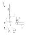
図1に、国際公開第2012/076844号に開示された出力送達システム100の概略図を示す。電力送達システム100は、本発明において使用するのに好適である。 FIG. 1 shows a schematic diagram of the output delivery system 100 disclosed in International Publication No. 2012/076844. The power delivery system 100 is suitable for use in the present invention.
システム100は、RFラインアップ102とマイクロ波ラインアップ104とを備え、これらはRFチャンネルおよびマイクロ波チャンネルの部分を形成する。 System 100 comprises an
RFラインアップ102は、後述のように、プラズマ発生のための好適な出力レベルでRF周波数電磁信号を発生および制御するための構成要素を含む。この実施形態では、RFラインアップ1002は、RF発振器1001と、出力コントローラ1002と、増幅器装置(ここでは、ドライバ増幅器1003と出力増幅器1004とを備える)と、変成器1005と、RF信号検出器1006とを含む。 The
マイクロ波ラインアップ104は、生体組織を処置するための好適な出力レベルでマイクロ波周波数電磁信号を発生および制御するための構成要素を含む。この実施形態では、マイクロ波ラインアップ104は、位相同期発振器1007と、信号増幅器1008と、調整可能な信号減衰器(例えば、アナログまたはデジタルPINダイオード式減衰器)1009と、増幅器装置(ここでは、ドライバ増幅器1010および出力増幅器1011)と、順方向パワーカプラ1012と、サーキュレータ1013と、反射パワーカプラ1014とを含む。サーキュレータ1013は、反射信号から順方向信号を絶縁して、カプラ1012、1014において望ましくない信号成分を減らす、すなわち、カプラの方向性を高める。サーキュレータはまた、高出力の段内のトランジスタ、例えば、パワーGaNまたはGaAsトランジスタを保護する。ポート1からポート3、ポート2からポート1およびポート3からポート2の間の絶縁をできるだけ大きくする、すなわち、15dB超にすることが望ましく、20dB超とすることがより好ましい。 The microwave lineup 104 includes components for generating and controlling microwave frequency electromagnetic signals at suitable power levels for treating living tissue. In this embodiment, the microwave lineup 104 includes a phase-synchronized oscillator 1007, a
RFラインアップ102およびマイクロ波ラインアップ104は、コントローラ106と通信し、コントローラ106は、信号処理および汎用インターフェース回路108と、マイクロコントローラ110と、ウォッチドッグ1015とを備えてもよい。ウォッチドッグ1015は、システムがその意図されている仕様の通りに動作しなくなる、すなわち、出力または処置時間がユーザが要求したものよりも大きいためにシステムが患者の組織へと誤った量のエネルギーを送達するような、潜在的なエラー状態の範囲監視してもよい。ウォッチドッグ1015は、マイクロコントローラ110とは独立のマイクロプロセッサを備えて、マイクロコントローラを確実に正しく機能させる。ウォッチドッグ1015は、例えば、DC電源からの電圧レベルまたはマイクロコントローラ110が決定したパルスのタイミングを監視してもよい。コントローラ106は、RFラインアップ102およびマイクロ波ラインアップ104の構成要素に制御信号を伝えるように構成される。この実施形態では、マイクロプロセッサ110は、RF制御信号CRFを出力コントローラ1002に出力し、またマイクロ波制御信号CMを調整可能な信号減衰器1009に出力するようにプログラムされている。これらの制御信号を利用して、RFラインアップ102からのRF EM放射出力およびマイクロ波ラインアップ104からのマイクロ波EM放射出力のエネルギー送達プロファイルを設定する。特に、出力コントローラ1002および調整可能な信号減衰器1009は、出力放射の出力レベルを制御することが可能である。さらに、出力コントローラ1002および調整可能な信号減衰器1009は、出力放射の波形(例えば、パルス幅、デューティサイクル、および振幅など)を設定可能なスイッチング回路を含んでもよい。The
マイクロプロセッサ110は、RF信号検出器1006および順方向および反射パワーカプラ1012、1014からの信号情報に基づいてRF制御信号CRFおよびマイクロ波制御信号CMを出力するようにプログラムされている。RF信号検出器1006は、RFチャンネル上のRF EM放射の電圧および電流(および任意で、電圧と電流との位相差)を示す信号または複数の信号SRFを出力する。この実施形態では、RFチャンネル(サンプリングした電流および電圧情報由来)またはマイクロ波チャンネル(サンプリングした順方向および反射電力情報由来)から取得され得る位相情報の測定値だけでRFおよびマイクロ波発生器を制御してもよい。順方向パワーカプラ1012は、順方向電力レベルを示す信号SM1を出力し、反射パワーカプラ1014は、反射電力レベルを示す信号SM2を出力する。RF信号検出器1006および順方向および反射パワーカプラ1012、1014からの信号SRF、SM1、SM2は、信号処理および汎用インターフェース回路108に伝えられ、そこでマイクロプロセッサ110に渡すのに適切な形態に適合される。The microprocessor 110 is programmed to output an RF control signalC RF and microwave control signalC M on the basis of the signal information from the
ユーザインターフェース112、例えば、タッチスクリーンパネル、キーボード、LED/LCDディスプレイ、メンブレンキーパッド、フットスイッチなどが、コントローラ106と通信して、ユーザ(例えば、外科医)に処置に関する情報を提供し、治療の様々な態様(例えば、患者へのエネルギー送達量、またはエネルギー送達プロファイル)を手動で、例えば、好適なユーザコマンドを介して選択または制御できるようにする。従来型のフットスイッチ1016を使用して装置を動作させてもよく、フットスイッチ1016もまたコントローラ106に接続される。 A user interface 112, such as a touch screen panel, keyboard, LED / LCD display, membrane keypad, footswitch, etc., communicates with controller 106 to provide the user (eg, surgeon) with information about the procedure and various treatments. Aspects (eg, energy delivery to the patient, or energy delivery profile) can be manually selected or controlled, eg, via suitable user commands. The device may be operated using the conventional foot switch 1016, which is also connected to the controller 106.
RFラインアップ102およびマイクロ波ラインアップ104によってそれぞれ生成されるRFおよびマイクロ波信号は、信号コンバイナ114に入力され、信号コンバイナ114は、RFおよびマイクロ波EM放射をケーブルアセンブリ116伝いにプローブ118へと別々または同時に運ぶ。この実施形態では、信号コンバイナ114は、デュプレクサ−ダイプレクサ装置を備え、これにより、マイクロ波およびRF周波数のエネルギーをケーブルアセンブリ116(例えば、同軸ケーブル)伝いにプローブ(またはアプリケータ)118まで伝送でき、プローブ118から患者生体組織内、スコープ、例えば、内視鏡の器具チャンネル内、または別の表面にエネルギーが送達される(例えば、放射される)。 The RF and microwave signals generated by the
信号コンバイナ114はまた、プローブ118からケーブルアセンブリ116伝いに跳ね返る反射エネルギーをマイクロ波およびRFラインアップ102、104内に通して、例えば、内部にある検出器に検出させる。後述のように、装置は、RFチャンネル上にローパスフィルタ146を含み、マイクロ波チャンネル上にハイパスフィルタ166を含んでもよく、それにより、反射RF信号のみがRFラインアップ102に入り、反射マイクロ波信号のみがマイクロ波ラインアップ104に入る。 The
最後に、装置は、外部電源1018(例えば、コンセントからの電力)から電力を受信し、装置内の構成要素のためにDC電源信号V1〜V6に変換する電力供給装置1017を含む。よって、ユーザインターフェースは、電力信号V1を受信し、マイクロプロセッサ110は、電力信号V3を受信し、RFラインアップ102は、電力信号V3を受信し、マイクロ波ラインアップは、電力信号V4を受信し、信号処理および汎用インターフェース回路108は、電力信号V5を受信し、ウォッチドッグ1015は、電力信号V6を受信する。Finally, the device receives power from an external power source 1018 (e.g., power from the wall outlet), a power supply device 1017 to convert the DC power signalsV 1 ~V6 for components within the device. Thus, the user interface receives the power signal V1 , the microprocessor 110 receives the power signal V3 , the
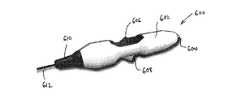
図2に、本発明の実施形態である電気手術装置200の概略図を示す。装置200は、その遠位端部からプラズマまたは非電離電磁(EM)放射を送達可能な電気手術器具202を備える。器具202の構造の例を以下に述べる。 FIG. 2 shows a schematic view of the electrosurgical apparatus 200 according to the embodiment of the present invention. The device 200 comprises an electrosurgical instrument 202 capable of delivering plasma or non-ionizing electromagnetic (EM) radiation from its distal end. An example of the structure of the instrument 202 will be described below.
器具202は、出力送達システムに接続され、出力送達システムは、図1を参照して説明したようなものであってよい。しかしながら、図2の実施形態では、出力送達システムは、供給構造208を介して器具202の近位端部に出力を送達するために接続されたラジオ波(RF)放射源204およびマイクロ波放射源206を備える。供給構造208は、上述のような信号コンバイナ装置210を含んでもよい。RF源204およびマイクロ波源206は、それぞれ、コントローラ(図示せず)からの制御信号CRFおよびCMに基づいて、RF信号およびマイクロ波信号を出力するように構成されてもよい。Instrument 202 is connected to an output delivery system, which may be as described with reference to FIG. However, in the embodiment of FIG. 2, the output delivery system is a radio frequency (RF) source 204 and a microwave source connected to deliver the output to the proximal end of the appliance 202 via the supply structure 208. It is equipped with 206. The supply structure 208 may include the signal combiner device 210 as described above. RF source 204 and
器具202はまた、例えば、加圧ガス源214から供給ライン212を介して、ガスを受け入れるように接続される。供給ライン212上の制御弁216は、例えば、コントローラからの制御信号Cgに基づいて、器具202によって受け入れたガスの流量を制御するように構成されてもよい。プラズマを発生させる前にプラズマ形成領域にガスが存在する必要があるため、前記エネルギー源が作動した時にガスを確実に存在させるために、RFおよび/またはマイクロ波エネルギー源を作動させる前に、ガス制御弁および/または流量コントローラを作動させることが望ましいこともある。プラズマ形成領域にガスセンサを含み、このセンサからの信号を使用してガス流量弁を制御することが好適な場合もある。このシステムはまた、ガス利用を制御するのを助け、および患者のアルゴン(または他の)ガス塞栓を防ぐ。The appliance 202 is also connected, for example, from a pressurized gas source 214 via a supply line 212 to receive gas. Control valve 216 on the supply line 212, for example, based on the control signal Cg from the controller may be configured to control the flow rate of the gas received by the instrument 202. Since the gas must be present in the plasma forming region before the plasma is generated, the gas must be present before the RF and / or microwave energy source is activated to ensure that the gas is present when the energy source is activated. It may be desirable to activate the control valve and / or flow controller. It may be preferable to include a gas sensor in the plasma forming region and use the signal from this sensor to control the gas flow valve. This system also helps control gas utilization and prevents argon (or other) gas embolism in the patient.
RFおよびマイクロ波測定情報はまた、ガスコントローラを制御するために使用されてもよい、すなわち、発生器内の電圧/電流および/または順方向/反射電力監視回路を用いてRFおよび/またはマイクロ波出力が検出されない場合、ガス制御弁を閉鎖してもよい。ガス供給を遮断する前に、設定された時間、すなわち、20msまたは200ms、待機することが好ましい場合もある。この構成は、安全機構として、またガス使用制御手段として働く。 RF and microwave measurement information may also be used to control the gas controller, i.e. RF and / or microwave using voltage / current and / or forward / reflected power monitoring circuitry within the generator. If no output is detected, the gas control valve may be closed. It may be preferable to wait for a set amount of time, ie 20 ms or 200 ms, before shutting off the gas supply. This configuration acts as a safety mechanism and as a gas use control means.
図3Aおよび図3Bに、本発明による電気手術器具300の第1の実施形態を示す。器具300は、管状スリーブ304に取り囲まれ、中央に同軸ケーブル302を備える細長いプローブを備える。同軸ケーブル302の近位端部(図3Aおよび図3Bの左手に示す)は、RFおよびマイクロ波信号を供給する供給構造に接続するように適合される好適なコネクタ306で終端する。同軸ケーブル302は、器具の遠位端部(図3Aおよび図3Bの右手)にRFおよびマイクロ波信号を伝える。 3A and 3B show a first embodiment of the electrosurgical instrument 300 according to the present invention. Instrument 300 is surrounded by a tubular sleeve 304 and comprises an elongated probe with a coaxial cable 302 in the center. The proximal end of coaxial cable 302 (shown on the left in FIGS. 3A and 3B) is terminated with a suitable connector 306 adapted to connect to a supply structure that supplies RF and microwave signals. Coaxial cable 302 carries RF and microwave signals to the distal end of the instrument (right hand in FIGS. 3A and 3B).
同軸ケーブル302の遠位端部は、短絡または絶縁破壊が生じるのを防ぐために、同軸ケーブルの本体と円筒形キャップとの間に配置されたガラスビーズまたはセラミックディスクなどの絶縁要素308で終端する。あるいは、マイクロ波ケーブル内の誘電体を例えば、0.1mm〜0.2mmだけ同軸ケーブルの外側導体を越えて延長させてもよい。同軸ケーブルの外側導体310は、絶縁要素308で止まるが、内側導体312は、絶縁要素308を通って続き、深部凝固のための最良のインピーダンス整合を与えるように(シミュレーションを使用して)選択された長さだけ絶縁要素308を越えて突出する。突出する長さは、円筒形セラミック(または他の好適な誘電体または磁性材料)キャップ314によって取り囲まれ、キャップ314は、その遠位端部においてドーム状316、例えば、半球になって終端する。内側導体312は、ドーム316からわずかに突出する。内側導体312および円筒形キャップは、器具の第1の電極として働く。 The distal end of the coaxial cable 302 is terminated with an insulating
スリーブ304は、同軸ケーブル302に対して長手方向に摺動するように構成される。この実施形態では、スリーブ304は、近位ベースピース318内において伸縮可能な仕方で摺動可能に設けられる。プルワイヤ(図示せず)がコネクタ306を通して延びて、同軸ケーブルに対するスリーブ304の配置を補助してもよい。プルワイヤは、手動で操作してもよいし、あるいは例えば、コントローラからの制御信号に基づいてスリーブ304の位置を自動的に制御する自動制御機構、例えば、ステッピングモータまたはリニアモータに接続してもよい。 The sleeve 304 is configured to slide in the longitudinal direction with respect to the coaxial cable 302. In this embodiment, the sleeve 304 is slidably provided within the proximal base piece 318 in a stretchable manner. A pull wire (not shown) may extend through the connector 306 to assist in the placement of the sleeve 304 with respect to the coaxial cable. The pull wire may be operated manually or may be connected to, for example, an automatic control mechanism that automatically controls the position of the sleeve 304 based on a control signal from the controller, such as a stepper motor or a linear motor. ..
プルワイヤは、一方の端部で同軸ケーブルに接続され、スリーブ(カテーテル)上を摺動するように構成される硬質な管の一部の形態であってもよい。2つのカテーテル部分を導入し、第1の部分を、「Y字」部分(同軸ケーブルでマイクロ波/RFエネルギーを、またチューブでガスを導入するために使用される)に固定される近位端部にすることが好ましい場合もある。「Y字」ピースへの2つの入力および共通の出力は、封止され、気密でなければならない。この目的のために、ねじを締めることによって調節可能な周囲封止部を有するルアーロック装置を使用してもよい。第1の硬質な部分は、内視鏡またはカニューレなどの器具チャンネルの内側に導入される第2のやや軟質の部分(メインカテーテル)の上で摺動するのであってもよい。硬質な近位部分および可撓性部分の間に封止部を設けて、ガスが2つの部分の接合部分から絶対に漏れることのないようにする。 The pullwire may be in the form of a portion of a rigid tube that is connected to a coaxial cable at one end and is configured to slide over a sleeve (catheter). Proximal end where two catheter parts are introduced and the first part is fixed to the "Y" part (used to introduce microwave / RF energy with coaxial cable and gas with tube) In some cases, it is preferable to make a part. The two inputs and common outputs to the "Y" piece must be sealed and airtight. For this purpose, luer lock devices with perimeter seals that can be adjusted by tightening screws may be used. The first rigid portion may slide over a second slightly soft portion (main catheter) that is introduced inside the instrument channel, such as an endoscope or cannula. A seal is provided between the rigid proximal portion and the flexible portion to ensure that gas never leaks from the junction of the two portions.
スリーブ304は、同軸ケーブル302を取り囲んで、同軸ケーブル302の外面およびスリーブ304の内面の間に環状空間320を画定する。同軸ケーブル302をスリーブ内に位置決めするために、放射状の支持要素またはスペーサ(図示せず)を使用してもよい。環状空間320を使用してガスを器具の遠位端部に輸送してもよい。ベースピース318は、その側面に、ガス供給ラインに接続されるポート322を有する。ガス漏れを最小にするために、ベースピース318およびコネクタ306の間の接合部、ならびにベースピースおよびスリーブ304の間の摺動接合部に、気密封止部324、326を設け、これは、Oリングなどであってもよい。したがって、ポート322内に導入されたガスは、環状空間320に沿って流れて、その遠位端部で器具から出る。 The sleeve 304 surrounds the coaxial cable 302 and defines an annular space 320 between the outer surface of the coaxial cable 302 and the inner surface of the sleeve 304. Radial support elements or spacers (not shown) may be used to position the coaxial cable 302 within the sleeve. The annular space 320 may be used to transport gas to the distal end of the instrument. The base piece 318 has a
スリーブ304は、その長さに沿いにその遠位端部に至る導電性内面321を有する。この導電性内面321は、同軸ケーブル302の外側導体310に電気接続される。この実施形態では、これは、環状空間320内に設けられた導電メッシュ328によってなされる。メッシュは多孔質であり、したがって、ガスを通過させることができると同時に、電気接続を提供する。このことはまた、導体または電極310および321の片面または両面に電気接続、すなわち、はんだ付けまたは圧着または捕捉されるばねまたは複数の小さいワイヤを用いて達成される。導体(複数可)の周囲に少なくとも2つの、理想的には少なくとも4つの、周囲接点を設けることによって、マイクロ波エネルギーが損なわれることなく伝播するのに十分に良好な電気接触を確実にすることができる。また、必要な電気接触を確立すると同時に、プラズマ発生領域またはプラズマが形成される機器の遠位端部へとガスを流すことができるようにするために、導体のうちの1つの中/上に複数の歯または部分的圧着(例えば、180°)を置くことが可能かつ好ましい場合もある。 The sleeve 304 has a conductive inner surface 321 that extends along its length to its distal end. The conductive inner surface 321 is electrically connected to the outer conductor 310 of the coaxial cable 302. In this embodiment, this is done by a conductive mesh 328 provided in the annular space 320. The mesh is porous and therefore allows gas to pass through while at the same time providing electrical connectivity. This is also achieved using electrical connections on one or both sides of the conductors or electrodes 310 and 321 that is, a spring or multiple small wires that are soldered or crimped or captured. Providing at least two, ideally at least four, peripheral contacts around the conductor (s) to ensure good electrical contact enough to propagate the microwave energy without loss. Can be done. Also, in / on one of the conductors to establish the required electrical contact and at the same time allow the gas to flow to the plasma generating region or the distal end of the device on which the plasma is formed. It may be possible and preferred to have multiple teeth or partial crimps (eg 180 °).
スリーブの導電性内面321は、円筒形キャップ314と長手方向に重なり合い得るその遠位長さに沿って絶縁チューブ330(例えば、石英、セラミックなどで作られたもの)によってさらに覆われる。導電性内面321および絶縁チューブ330は、器具の第2の電極として働く。 The conductive inner surface 321 of the sleeve is further covered by an insulating tube 330 (eg, made of quartz, ceramic, etc.) along its distal length that may overlap the cylindrical cap 314 in the longitudinal direction. The conductive inner surface 321 and the insulating
摺動可能なスリーブにより、器具は2つの構成を取り入れることができる。第1の構成では、図3Bに示すように、スリーブ304の導電性内面321は、円筒形キャップ314と長手方向に一致している。この構成では、RFまたはマイクロ波信号が器具に供給された時に高電場を呈する高インピーダンス領域が設定される。この構成では、器具は、プローブの遠位端部からプラズマ、例えば、表面凝固のための熱プラズマを、あるいは滅菌のための非熱プラズマを送達するように適合されてもよい。 The slidable sleeve allows the instrument to incorporate two configurations. In the first configuration, as shown in FIG. 3B, the conductive inner surface 321 of the sleeve 304 coincides with the cylindrical cap 314 in the longitudinal direction. In this configuration, a high impedance region is set that exhibits a high electric field when an RF or microwave signal is supplied to the instrument. In this configuration, the instrument may be adapted to deliver plasma, eg, thermal plasma for surface coagulation, or non-thermal plasma for sterilization, from the distal end of the probe.
マイクロプロセッサは、マイクロ波検出信号からコントローラで判定される検出された反射損失またはインピーダンス不整合に基づいて、同軸ケーブルに対して摺動スリーブの位置を調整するための制御信号を出力するように構成されてもよい。この制御は、例えば、既定の必要とされる整合または反射損失、例えば、10dB(マイクロ波エネルギーの90%がプラズマへと送達される)を維持するように、プラズマ発生時になされてもよい。 The microprocessor is configured to output a control signal for adjusting the position of the sliding sleeve with respect to the coaxial cable based on the detected reflection loss or impedance mismatch determined by the controller from the microwave detection signal. May be done. This control may be made at the time of plasma generation, for example, to maintain a predetermined required matching or return loss, eg, 10 dB (90% of microwave energy is delivered to the plasma).
好適な実施形態では、プラズマ(必要に応じて熱プラズマまたは非熱プラズマ)は、以下のステップで発生される。
−器具の遠位領域に(すなわち、石英チューブ330および円筒形キャップ314の間の領域に)ガスを供給し、
−遠位領域で高電場を発生させることによってその領域でガスにおいてプラズマを発生させるために同軸ケーブルを通してRFエネルギーのパルスを送信し、
−確実に適切な処置がなされるように、プラズマを維持するために同軸ケーブルを通してマイクロ波エネルギーのパルスを送信する。In a preferred embodiment, the plasma (optionally thermal or non-thermal plasma) is generated in the following steps.
-Supply gas to the distal region of the instrument (ie, the region between the
-Send a pulse of RF energy through a coaxial cable to generate a plasma in the gas in that region by generating a high electric field in the distal region,
-Send microwave energy pulses through coaxial cable to maintain the plasma to ensure proper treatment.
マイクロ波パルスの特性(例えば、立ち上がりエッジ)によって、RFパルスを自動的に発して、パルスの発生および維持を常に同期させてもよい。RFパルスは、プラズマ発生のための電場を設けるのに好適な電圧を有するように構成される。電圧は、ピーク値で150V〜1500Vの間であってもよく、より好ましくは、ピーク値で250V〜750Vの間である。RFパルスの周波数は、100kHz〜1MHzの間であってもよく、ここでは、正弦波または信号の窓またはバーストが(検出されたマイクロ波パルスに基づいて)ゲーティングされ、好ましくは、0.5μs〜10msの間である。 Depending on the characteristics of the microwave pulse (eg, the rising edge), an RF pulse may be automatically emitted to synchronize the generation and maintenance of the pulse at all times. The RF pulse is configured to have a voltage suitable for providing an electric field for plasma generation. The voltage may be between 150V and 1500V at the peak value, more preferably between 250V and 750V at the peak value. The frequency of the RF pulse may be between 100 kHz and 1 MHz, where a sinusoidal or signal window or burst is gated (based on the detected microwave pulse), preferably 0.5 μs. It is between 10 ms.
プラズマの状態を確認するために、送達されるマイクロ波出力を監視してもよい(例えば、順方向および反射マイクロ波信号を測定することによって)。 To check the state of the plasma, the delivered microwave output may be monitored (eg, by measuring forward and reflected microwave signals).
上述の実施形態では、RF信号によってプラズマを発生させる。他の実施形態では、内側および外側導体の間の距離が密接していることにより、マイクロ波信号から高電場を発生できるため、マイクロ波信号のみでプラズマを発生させてもよい。例えば、器具の遠位端部に25WのCWマイクロ波出力を送達可能である場合、これにより十分な高電場を作成し得る。マイクロ波場を使用する、プラズマ発生の1つの可能な手段は、プラズマ発生時にプラズマ発生領域内の2つの導体間の距離を短くし、次いで、プラズマが発生したならば、プラズマを維持するための最適な環境(インピーダンス)を作るために再び距離を取ることである。この構成では、調整可能スリーブ(外側チューブ)を4つの可能な位置となるように、あるいは準備されるように構成してもよい。4つの可能な位置とは、すなわち:
位置1−深部凝固のための非電離マイクロ波放射を送達するためにモノポール放射アンテナが露出される;
位置2−プラズマ発生領域の設定:放射モノポールが外側スリーブによって覆われ、RFおよびマイクロ波エネルギーを使用してプラズマ(表面凝固には熱プラズマおよび/または滅菌/消毒には非熱プラズマ)を発生および維持し得るようにガスがその領域内に導入される;
位置3−マイクロ波エネルギーを使用してプラズマを発生させ、内側導体および外側導体の間の距離を調整してプラズマ発生に足る高電場を発生させる;
位置4−マイクロ波場を使用してプラズマを維持し、内側導体および外側導体の間の距離を調整してプラズマが維持されるような低インピーダンス環境を生成させる。In the above embodiment, plasma is generated by an RF signal. In other embodiments, the close distance between the inner and outer conductors allows a high electric field to be generated from the microwave signal, so the plasma may be generated solely from the microwave signal. For example, if a 25 W CW microwave output can be delivered to the distal end of the instrument, this can create a sufficiently high electric field. One possible means of plasma generation using a microwave field is to reduce the distance between two conductors in the plasma generation region during plasma generation and then to maintain the plasma if it is generated. It is to take a distance again to create the optimum environment (impedance). In this configuration, the adjustable sleeve (outer tube) may be configured to be in four possible positions or prepared. The four possible positions are:
Position 1-A monopole radiation antenna is exposed to deliver non-ionizing microwave radiation for deep coagulation;
Position 2-Plasma generation region setting: The radiating monopole is covered by an outer sleeve and uses RF and microwave energy to generate plasma (thermal plasma for surface coagulation and / or non-thermal plasma for sterilization / disinfection). And gas is introduced into the area so that it can be maintained;
Position 3-Microwave energy is used to generate plasma and the distance between the inner and outer conductors is adjusted to generate a high electric field sufficient for plasma generation;
Position 4-Microwave fields are used to maintain the plasma and the distance between the inner and outer conductors is adjusted to create a low impedance environment in which the plasma is maintained.
スリーブの位置の制御および様々な領域の形成は、RFチャンネルからの電圧および/または電流信号、ならびに/あるいはマイクロ波チャンネルからの順方向および/または反射電力信号に基づくリニアアクチュエータまたはステッピングモータの動作に基づいて自動的に行ってもよい。 Controlling the position of the sleeve and forming various regions is responsible for the operation of linear actuators or stepper motors based on voltage and / or current signals from RF channels and / or forward and / or reflected power signals from microwave channels. It may be done automatically based on.
絶縁チューブ330および円筒形キャップ314を含む同軸部分が、50オームのインピーダンスを有する場合、ピーク電圧は50Vになり、その結果、内側導体312およびスリーブ304導体の導電性内面の間の距離が1mmであれば、50kV/mの電場が生成される。そのような電場は、間隙にアルゴンが存在すれば、プラズマを発生させることができる。インピーダンス変成器、すなわち、四分の一波長変成器に切り替えて、プラズマ発生に必要な電圧増加をもたらすことが可能な場合もある。例えば、インピーダンスが250Ωの四分の一波長線路において、50Ωのソースインピーダンスおよび25Wの電力源の場合、発生電圧は、次のようになる:
そのような実施形態では、器具は、マイクロ波入力のみを受信してもよい;この構成では、出力送達システムは、RF源を持たなくてもよい。 In such an embodiment, the instrument may receive only microwave inputs; in this configuration, the output delivery system may not have an RF source.
第2の構成では、図3Aに示すように、スリーブ304は、同軸ケーブル302に対して摺動して下がって、機器の遠位端部で円筒形キャップ314をある長さ露出する。露出した端部は、放射モノポールマイクロ波アンテナとして働く。この構成では、マイクロ波信号は、ガスなしで同軸ケーブルに供給される。マイクロ波信号は、非電離放射場で放出されて深部組織凝固を行う。遠位放射モノポールに送達される非電離マイクロ波出力のレベルは、連続波出力2.5W〜50Wの間であってもよく、このレベルは、血流量または凝固する血管の大きさに依存する。出力レベルはまた、発生器からアプリケータまたはアンテナにマイクロ波エネルギーを送達するのに使用されるマイクロ波伝送ケーブルの特性に依存する。 In the second configuration, as shown in FIG. 3A, the sleeve 304 slides down with respect to the coaxial cable 302, exposing the cylindrical cap 314 to a length at the distal end of the device. The exposed end acts as a radiating monopole microwave antenna. In this configuration, the microwave signal is fed to the coaxial cable without gas. The microwave signal is emitted in a non-ionizing radiation field to cause deep tissue coagulation. The level of non-ionizing microwave output delivered to the distal radiating monopole may be between 2.5 W and 50 W continuous wave output, which depends on blood flow or the size of the coagulating vessel. .. The output level also depends on the characteristics of the microwave transmission cable used to deliver microwave energy from the generator to the applicator or antenna.
図4A、図4Bおよび図4Cに、本発明による電気手術器具400の第2の実施形態を示す。図3Aおよび図3Bと共通の特徴には、同じ参照番号を付与してある。第2の実施形態は、第1の実施形態に類似しているが、同軸ケーブル302の外側導体310のスリーブ304の導電性内面321への電気接続の仕方が異なる。導電メッシュではなく、第2の実施形態は、導電性材料製の分裂円錐部材402を使用して、同軸ケーブル302の外側導体310をスリーブ304の導電性内面321に接続する。円錐部材402は、同軸ケーブルからスリーブ304に向けてラッパ状に広がる複数の指部を備える。スリーブ304は、指部に対して摺動してもよく、あるいは円錐部材402は、スリーブに固定させて、同軸ケーブル上で摺動させてもよい。 4A, 4B and 4C show a second embodiment of the electrosurgical instrument 400 according to the present invention. Features common to FIGS. 3A and 3B are given the same reference numbers. The second embodiment is similar to the first embodiment, but the method of electrically connecting the sleeve 304 of the outer conductor 310 of the coaxial cable 302 to the conductive inner surface 321 is different. In a second embodiment, rather than a conductive mesh, a split
図4Bは、分裂円錐部材402を通る断面図を示し、これは、ガスが指部の間をどのように通過してプローブの遠位端部に到達し得るかを示している。 FIG. 4B shows a cross-sectional view through the split
図4Cは、第1の構成にある器具を示し、図4Aは、上述の第2の構成にある器具を示している。 FIG. 4C shows the instrument in the first configuration and FIG. 4A shows the instrument in the second configuration described above.
図5は、上述の電気手術器具の第1の電極の一部を形成する円筒形キャップを模するために使用される誘電体円筒の斜視図である。約2mmの直径および6.7mmの長さを有する丸みを帯びた円筒は、5.8GHzのマイクロ波出力で肝臓組織内に良好に適合し、したがって、深部凝固モード(すなわち、第2の構成)におけるエネルギーの効率的な送達に有用であることが分かっている。図6A〜図6Cに示すように、この構造から放出される非電離放射によってもたらされる加熱は、内側導体の端部を中心とした径1mmの極めて小さい領域に及ぶ。図6Aおよび図6Bは、角ばった縁部を有する鋭利な平坦面で終端する内側導体を示している。電場は、角ばった縁部で非常に大きくなっている。図6Cは、ドーム(例えば、半球)状に終端する内側導体を示し、ドームにより、電場がより均等になる。 FIG. 5 is a perspective view of a dielectric cylinder used to mimic a cylindrical cap that forms part of the first electrode of the electrosurgical instrument described above. A rounded cylinder with a diameter of about 2 mm and a length of 6.7 mm fits well into the liver tissue at a microwave output of 5.8 GHz and therefore a deep coagulation mode (ie, a second configuration). It has been found to be useful for efficient delivery of energy in. As shown in FIGS. 6A-6C, the heating provided by the non-ionizing radiation emitted from this structure extends to a very small area with a diameter of 1 mm centered on the end of the inner conductor. 6A and 6B show an inner conductor terminating with a sharp flat surface with angular edges. The electric field is very large at the angular edges. FIG. 6C shows an inner conductor terminating in a dome (eg, hemisphere) shape, which makes the electric field more even.
図7Aおよび図7Bは、それぞれ、図6Cおよび図6Bの構造の反射損失のグラフを示している。概して、この実施形態においてマイクロ波信号に関して使用された周波数(5.8GHz)付近で組織への良好な適合を示している。図7Aは、内側導体上の半球端部が整合周波数を低下させることを示しているが、このことは、キャップの長さを短くすることによって容易に調整できる。 7A and 7B show graphs of return loss for the structures of FIGS. 6C and 6B, respectively. In general, it shows good tissue fit near the frequency (5.8 GHz) used for microwave signals in this embodiment. FIG. 7A shows that the hemispherical end on the inner conductor lowers the matching frequency, which can be easily adjusted by reducing the length of the cap.
図8Aおよび図8Bは、それぞれ、血液および肝臓組織内におけるHuber & Suhner社のSucoform86マイクロ波ケーブルなど(すなわち、直径2.2mmのケーブル)の遠位端部で終端する円筒形キャップのマイクロ波場シミュレーションである。この構成では、円筒形キャップに使用される材料はPEEKであり、半球までの円筒形部分の長さは、3mmであった。よって、キャップ(例えば、PEEK製)は、2〜2.1mmの直径および4〜4.1mmの全長を有する。この構成では、内側導体の端部におけるドームは、直径1mmでモデリングされている。同様に、このような構造からの加熱は、遠位先端の周囲に限られている。 8A and 8B show the microwave field of a cylindrical cap terminating at the distal end of a Huber & Shuner Sucoform 86 microwave cable or the like (ie, a 2.2 mm diameter cable) in blood and liver tissue, respectively. It is a simulation. In this configuration, the material used for the cylindrical cap was PEEK, and the length of the cylindrical portion up to the hemisphere was 3 mm. Thus, the cap (eg, made by PEEK) has a diameter of 2 to 2.1 mm and a total length of 4 to 4.1 mm. In this configuration, the dome at the end of the inner conductor is modeled with a diameter of 1 mm. Similarly, heating from such structures is confined to the periphery of the distal tip.
図9Aおよび図9Bは、それぞれ、図8Aおよび図8Bの構造の反射損失のグラフを示している。目的の周波数(約5.8GHz)における損失は許容される。 9A and 9B show graphs of return loss for the structures of FIGS. 8A and 8B, respectively. Losses at the desired frequency (about 5.8 GHz) are acceptable.
図10は、肝臓組織内におけるHuber & Suhner社のSucoform47マイクロ波ケーブルなど(すなわち、直径1.2mmのケーブル)の遠位端部で終端する円筒形キャップのマイクロ波場シミュレーションである。この構成では、円筒形キャップに使用される材料もまたPEEKであり、半球までの円筒形部分の長さもまた3mmであった。しかしながら、この構成では、キャップの直径は1.2mmであり、したがって、全長は約3.6mmとなる。この構成では、内側導体の端部におけるドームは、直径0.5mmでモデリングされている。 FIG. 10 is a microwave field simulation of a cylindrical cap terminating at the distal end of a Huber & Sunner Sucoform 47 microwave cable or the like (ie, a 1.2 mm diameter cable) in liver tissue. In this configuration, the material used for the cylindrical cap was also PEEK, and the length of the cylindrical portion up to the hemisphere was also 3 mm. However, in this configuration, the cap diameter is 1.2 mm and therefore the overall length is about 3.6 mm. In this configuration, the dome at the end of the inner conductor is modeled with a diameter of 0.5 mm.
図11Aおよび図11Bは、それぞれ、血液および肝臓組織内における図10の構造の反射損失のグラフを示している。同様に、目的の周波数(約5.8GHz)における損失は許容される。 11A and 11B show graphs of the reflex loss of the structure of FIG. 10 in blood and liver tissue, respectively. Similarly, a loss at the desired frequency (about 5.8 GHz) is acceptable.
図12Aおよび図12Bは、本発明の実施形態である電気手術器具500の概略断面図を示しており、電気手術器具500は、図6〜図11を参照して上に説明したマイクロ波放出構造を利用している。 12A and 12B show schematic cross-sectional views of an
図12Aは、遠位端部でプラズマを送達するのに好適な第1の構成にある電気手術器具500を示している。器具500は円筒形であり、内視鏡検査機器、例えば、内視鏡の器具チャンネルを通るのに適した寸法にされている。器具は、内側導体504と、誘電材料508によって内側導体504から隔てられた外側導体506とを有する同軸ケーブル502を備える。外側導体506は、同軸ケーブル502の外面の周囲に露出する。同軸ケーブル502の遠位端部では、内側導体504が外側導体506を越えて延び、例えば、PEEK製などの誘電体キャップ510によって取り囲まれている。キャップ510は、同軸ケーブル502と実質的に同じ直径を有する円筒である。キャップ510の遠位端部は、丸みを帯びた、例えば、半球のドームを形成する。内側導体504は、その遠位端部で、キャップ510の端部を越えて突出する丸みを帯びた先端512として終端する。 FIG. 12A shows an
同軸ケーブル502は、スリーブ514内に設けられ、スリーブは、強化用に内部編組(図示せず)を含むことが好ましい。スリーブ514の近位端部から遠位端部に導入されるガスを輸送するためのガス流路を形成する環状間隙516が、スリーブ514の内面および同軸ケーブル502の外面(すなわち、露出した外側導体)の間に存在する。 The coaxial cable 502 is preferably provided within the sleeve 514, which preferably includes an internal braid (not shown) for reinforcement. An annular gap 516 forming a gas flow path for transporting the gas introduced from the proximal end to the distal end of the sleeve 514 is the inner surface of the sleeve 514 and the outer surface of the coaxial cable 502 (ie, the exposed outer conductor). ) Exists.
導電性端子チューブ518をスリーブ514の遠位端部に設ける。例えば、導電性端子チューブ518をスリーブ514に溶接してもよい。図12Aに示す構成では、内側導体504の丸みを帯びた先端512が、第1の電極を形成し、導電性端子チューブ518が第2の電極を形成する。環状間隙516から流れるガス中でプラズマを発生させるための電場は、上述のように好適なエネルギー(例えば、RFおよび/またはマイクロ波周波数エネルギー)を同軸ケーブルに印可することによって、第1の電極および第2の電極の間で形成される。 A conductive terminal tube 518 is provided at the distal end of the sleeve 514. For example, the conductive terminal tube 518 may be welded to the sleeve 514. In the configuration shown in FIG. 12A, the rounded tip 512 of the inner conductor 504 forms the first electrode and the conductive terminal tube 518 forms the second electrode. The electric field for generating the plasma in the gas flowing from the annular gap 516 is the first electrode and by applying suitable energy (eg RF and / or microwave frequency energy) to the coaxial cable as described above. It is formed between the second electrodes.
導電性端子チューブ518は、導電性端子チューブ518の内面上にある複数の放射状に突出す突起520によって、同軸ケーブル502の外側導体506に電気接続される。導電性端子チューブ518の内周にわたって互いに離間する2つ、3つ、4つ以上の突起520が存在してもよい。突起をこのように離間させることにより、ガスを通すことができる。 The conductive terminal tube 518 is electrically connected to the outer conductor 506 of the coaxial cable 502 by a plurality of radially projecting protrusions 520 on the inner surface of the conductive terminal tube 518. There may be two, three, four or more protrusions 520 that are spaced apart from each other over the inner circumference of the conductive terminal tube 518. By separating the protrusions in this way, gas can pass through.
導電性端子チューブ518の内面の周囲にその遠位長さに沿って絶縁ライナ522を設ける。絶縁ライナ522は、ポリイミドなどから作られてもよい。ライナ522の目的は、加えたRFおよび/またはマイクロ波周波数エネルギーがプラズマ発生のための高電圧を有する電場を確実に生じるように、第1の電極および第2の電極の間に好適な誘電体バリヤを提供することである。ライナ522およびキャップ510の間に小さな間隙が存在してガスを通す。 An insulating liner 522 is provided around the inner surface of the conductive terminal tube 518 along its distal length. The insulating liner 522 may be made of polyimide or the like. The purpose of the liner 522 is to ensure that the added RF and / or microwave frequency energy produces an electric field with a high voltage for plasma generation, a suitable dielectric between the first and second electrodes. To provide a barrier. There is a small gap between the liner 522 and the cap 510 to allow gas to pass through.
図12Bは、その遠位端部で非電離マイクロ波周波数エネルギーを送達するのに好適な第2の構成にある電気手術器具500を示している。この構成では、キャップ510は、導電性端子チューブ518から延出し、それにより、上述のモノポーラマイクロ波アンテナを形成する。 FIG. 12B shows an
器具500を第1の構成および第2の構成の間で変形するには、スリーブ514に対して軸方向に同軸ケーブル502を摺動させる。摺動操作は、外科医が操作し得る器具の近位ハンドピース上に設けられた物理的なスライダスイッチによって達成されてもよい。 To deform the
図13は、本発明の実施形態である電気手術器具で使用される、あるいはその一部を構成するハンドピース600の斜視図を示している。ハンドピースは、内部構成要素を取り囲んで保護するためのハウジング602またはシェルを備える。ハウジングは、その後端に、同軸ケーブルに接続するための近位ポート604を有して、電気手術用発生器(図示せず)からRFおよび/またはマイクロ波周波数エネルギーを受信する。ハウジング602の中央部分には、器具の遠位端部における構成を変えるためのスライダスイッチ606がある。スライダスイッチ606から反対側のハウジングには、好適なガス供給管(図示せず)に取り付けるためのガス受入ポート608がある。ハウジング602の遠位端部には、ガスおよびエネルギーを処置部位に送るスリーブ612のための保護案内部として働く可撓性ノズル610がある。 FIG. 13 shows a perspective view of a
図14は、ハウジング602の内部構成要素の断面図を示している。同軸ケーブル614は、近位ポート604からハウジングを通って延びている。例えば、ステンレス鋼製のカラー616が、同軸ケーブル614の近位端部に設けられている(例えば、はんだ付けされている)。スライダスイッチ606は、グラブねじ618でカラー616に取り付けられる。この構成は、スライダスイッチ606を同軸ケーブルにこれを損傷することなく確実にしっかりと固定し得るようにする。 FIG. 14 shows a cross-sectional view of the internal components of the
同軸ケーブル614は、Y字形接合部620の第1の入力ポートに受容される。Y字形接合部620の第2の入力ポートは、ガス受入ポート608に接続される。Y字形接合部620内に導入されたガスは、適切な封止部622により第1の入力ポートから漏れないようにされる。 The coaxial cable 614 is received by the first input port of the Y-shaped junction 620. The second input port of the Y-shaped joint 620 is connected to the
同軸ケーブル614は、Y字形接合部620を通って延び、出力ポートから出る。スリーブ612の近位端部は、Y字形接合部620の出力ポートに固定され(例えば、接着される)、Y字形接合部620は、ガス受入ポート608からのガスおよび同軸ケーブルの両方を受容する。使用の際、スライダスイッチ606は、同軸ケーブル614をスリーブ612内で伸縮するように、ハウジング602に対して移動可能である。スライダスイッチの動作範囲は、20mmであってもよい。 Coaxial cable 614 extends through the Y-joint 620 and exits the output port. The proximal end of the sleeve 612 is secured (eg, glued) to the output port of the Y-shaped junction 620, which receives both gas and coaxial cable from the
Claims (8)
Translated fromJapaneseラジオ波(RF)およびマイクロ波周波数電磁(EM)放射を伝えるための同軸ケーブル、ならびに前記RFおよびマイクロ波放射を前記同軸ケーブルから別々にあるいは同時に受信するために前記同軸ケーブルの遠位端部に接続されるプローブ先端を備える細長いプローブと、
前記細長いプローブを通して前記プローブ先端までガスを運ぶためのガス通路と、
を備え、
前記同軸ケーブルが、内側導体、外側導体および前記内側導体を前記外側導体と隔てる誘電材料を備え、
前記プローブ先端が、前記同軸ケーブルの前記内側導体に接続される第1の電極および前記同軸ケーブルの前記外側導体に接続される第2の電極を備え、
前記第1の電極および第2の電極が互いに同軸であり、かつ
前記ガス通路から受け入れた前記ガスの流路を横切るように、受信した前記RF EM放射のエネルギーから電場を生成して、プラズマが発生し、かつ
前記プラズマが発生した後に、受信した前記マイクロ波のエネルギーを送達して前記プラズマを維持するように、前記第1の電極および第2の電極が構成され、
ガスを流すことができるガス透過性導電構造によって、前記同軸ケーブルの前記外側導体を前記第2の電極に接続する、
電気手術器具。It ’s an electric surgical instrument,
A coaxial cable for transmitting radio frequency (RF) and microwave frequency electromagnetic (EM) radiation, and at the distal end of the coaxial cable to receive the RF and microwave radiation separately or simultaneously from the coaxial cable. An elongated probe with a probe tip to be connected and
A gas passage for carrying gas through the elongated probe to the tip of the probe,
With
The coaxial cable comprises an inner conductor, an outer conductor, and a dielectric material that separates the inner conductor from the outer conductor.
The probe tip comprises a first electrode connected to the inner conductor of the coaxial cable and a second electrode connected to the outer conductor of the coaxial cable.
The plasma generates an electric field from the energy of the received RF EM radiation so that the first electrode and the second electrode are coaxial with each other and cross the flow path of the gas received from the gas passage. The first and second electrodes are configured to deliver the energy of the microwave received and maintain the plasma after it has been generated and the plasma has been generated.
The outer conductor of the coaxial cable is connected to the second electrode by a gas permeable conductive structure capable of flowing gas.
Electric surgical instruments.
導電性メッシュ、
放射状に延びる導電性ワイヤまたはばねのケージ、および
複数の周縁方向に離間した放射状に突出する歯(dents)
のうちのいずれかである、請求項1に記載の電気手術器具。The gas-permeable conductive structure
Conductive mesh,
Radial conductive wire or spring cages, and multiple peripherally spaced radially protruding teeth.
The electric surgical instrument according to claim 1, which is any of the above.
ラジオ波(RF)信号発生器であって、第1の周波数を有するRF電磁(EM)放射を生成するためのRF信号発生器と、
前記第1の周波数よりも高い第2の周波数を有するマイクロ波EM放射を発生するためのマイクロ波信号発生器と、
前記RF EM放射および前記マイクロ波EM放射を受信するように接続される請求項1に記載の電気手術器具と、
前記プローブに前記RF EM放射および前記マイクロ波EM放射を伝えるための供給構造であって、前記供給構造が、前記RF信号発生器に前記プローブを接続するためのRFチャンネルと、および前記プローブを前記マイクロ波信号発生器に接続するためのマイクロ波チャンネルを備える、供給構造と、
電気手術器具にガスを供給するように接続されるガス供給部と
を備え、
前記装置が、
表面凝固モードで動作可能であり、それによって、前記プローブ先端に送達される前記RF EM放射が前記第1および第2の電極の間でガスプラズマを発生するように構成され、かつ
前記マイクロ波EM放射がプラズマ発生後に前記プラズマを維持するように構成される、電気手術装置。An electrosurgical device for coagulation
A radio frequency (RF) signal generator, an RF signal generator for generating RF electromagnetic (EM) radiation having a first frequency,
A microwave signal generator for generating microwave EM radiation having a second frequency higher than the first frequency,
The electrosurgical instrument according to claim 1, which is connected to receive the RF EM radiation and the microwave EM radiation.
A supply structure for transmitting the RF EM radiation and the microwave EM radiation to the probe, wherein the supply structure provides an RF channel for connecting the probe to the RF signal generator, and the probe. A supply structure with a microwave channel for connecting to a microwave signal generator,
Equipped with a gas supply unit connected to supply gas to the electrosurgical instrument,
The device
It can operate in surface coagulation mode, whereby the RF EM radiation delivered to the probe tip is configured to generate a gas plasma between the first and second electrodes, and the microwave EM. An electrosurgical apparatus in which radiation is configured to maintain the plasma after it has been generated.
前記マイクロ波検出信号を受信するための前記マイクロ波信号検出器と通信可能なコントローラと
を備え、
前記コントローラが、前記マイクロ波EMエネルギーのためのエネルギー送達プロファイルを選択するように動作可能であり、前記マイクロ波EMエネルギーのための前記エネルギー送達プロファイルが組織の凝固のためのものであり、
前記コントローラが、前記マイクロ波信号発生器のためのマイクロ波制御信号を出力するようにプログラムされたデジタルマイクロプロセッサを備え、前記マイクロ波制御信号が、前記マイクロ波EMエネルギーのための前記エネルギー送達プロファイルを設定するためのものであり、
前記コントローラが、前記受信したマイクロ波検出信号に基づいて前記マイクロ波制御信号の状態を判定するように構成される、
請求項6に記載の電気手術装置。
Sampling the forward and reflected power on the microwave channel, and from there, a microwave signal detector for generating a microwave detection signal indicating thatthe microwave output is deliveredby the probe ,
A controller capable of communicating with the microwave signal detector for receiving the microwave detection signal is provided.
The controller can operate to select an energy delivery profile for the microwave EM energy, and the energy delivery profile for the microwave EM energy is for tissue coagulation.
The controller comprises a digital microprocessor programmed to output a microwave control signal for the microwave signal generator, wherein the microwave control signal is the energy delivery profile for the microwave EM energy. Is for setting
The controller is configured to determine the state of the microwave control signal based on the received microwave detection signal.
The electrosurgical apparatus according to claim6 .
Applications Claiming Priority (2)
| Application Number | Priority Date | Filing Date | Title |
|---|---|---|---|
| GB1308558.4 | 2013-05-13 | ||
| GBGB1308558.4AGB201308558D0 (en) | 2013-05-13 | 2013-05-13 | Electrosurgical apparatus |
Related Parent Applications (1)
| Application Number | Title | Priority Date | Filing Date |
|---|---|---|---|
| JP2018149775ADivisionJP6605673B2 (en) | 2013-05-13 | 2018-08-08 | Dual-function plasma and non-ionizing microwave coagulation electrosurgical instrument and electrosurgical device incorporating the same |
Publications (2)
| Publication Number | Publication Date |
|---|---|
| JP2020011083A JP2020011083A (en) | 2020-01-23 |
| JP6829449B2true JP6829449B2 (en) | 2021-02-10 |
Family
ID=48672221
Family Applications (3)
| Application Number | Title | Priority Date | Filing Date |
|---|---|---|---|
| JP2016513434AActiveJP6386030B2 (en) | 2013-05-13 | 2014-05-13 | Dual-function plasma and non-ionizing microwave coagulation electrosurgical instrument and electrosurgical device incorporating the same |
| JP2018149775AActiveJP6605673B2 (en) | 2013-05-13 | 2018-08-08 | Dual-function plasma and non-ionizing microwave coagulation electrosurgical instrument and electrosurgical device incorporating the same |
| JP2019164916AActiveJP6829449B2 (en) | 2013-05-13 | 2019-09-10 | Dual-function plasma and non-ionizing microwave coagulation electrosurgical instruments and electrosurgical instruments incorporating them |
Family Applications Before (2)
| Application Number | Title | Priority Date | Filing Date |
|---|---|---|---|
| JP2016513434AActiveJP6386030B2 (en) | 2013-05-13 | 2014-05-13 | Dual-function plasma and non-ionizing microwave coagulation electrosurgical instrument and electrosurgical device incorporating the same |
| JP2018149775AActiveJP6605673B2 (en) | 2013-05-13 | 2018-08-08 | Dual-function plasma and non-ionizing microwave coagulation electrosurgical instrument and electrosurgical device incorporating the same |
Country Status (14)
| Country | Link |
|---|---|
| US (2) | US10342595B2 (en) |
| EP (1) | EP2996768B1 (en) |
| JP (3) | JP6386030B2 (en) |
| KR (1) | KR102254258B1 (en) |
| CN (1) | CN105592886B (en) |
| AU (2) | AU2014267060B2 (en) |
| BR (1) | BR112015028276B1 (en) |
| CA (1) | CA2912280C (en) |
| DK (1) | DK2996768T3 (en) |
| ES (1) | ES2638791T3 (en) |
| GB (3) | GB201308558D0 (en) |
| PT (1) | PT2996768T (en) |
| SG (1) | SG11201509090QA (en) |
| WO (1) | WO2014184544A1 (en) |
Families Citing this family (63)
| Publication number | Priority date | Publication date | Assignee | Title |
|---|---|---|---|---|
| GB201308558D0 (en)* | 2013-05-13 | 2013-06-19 | Creo Medical Ltd | Electrosurgical apparatus |
| KR101810926B1 (en)* | 2015-08-19 | 2017-12-20 | 한국전자통신연구원 | Apparatus for Generating Plasma and Method for Supplying Plasma using the same |
| US10245333B2 (en) | 2015-08-19 | 2019-04-02 | Electronics And Telecommunications Research Institute | Plasma generating apparatus and treatment method using the same |
| FR3042092B1 (en)* | 2015-10-05 | 2019-07-26 | Sairem Societe Pour L'application Industrielle De La Recherche En Electronique Et Micro Ondes | ELEMENTARY DEVICE FOR PRODUCING PLASMA WITH COAXIAL APPLICATOR |
| GB2547941A (en)* | 2016-03-04 | 2017-09-06 | Creo Medical Ltd | Electrosurgical instrument |
| GB2552921A (en) | 2016-04-04 | 2018-02-21 | Creo Medical Ltd | Electrosurgical probe for delivering RF and microwave energy |
| GB2550414A (en)* | 2016-05-20 | 2017-11-22 | Creo Medical Ltd | Antenna structure |
| GB2551117A (en) | 2016-05-31 | 2017-12-13 | Creo Medical Ltd | Electrosurgical apparatus and method |
| DE102016110705A1 (en)* | 2016-06-10 | 2017-12-14 | Olympus Winter & Ibe Gmbh | Electrosurgical instrument, electrosurgical system and method of making an electrosurgical instrument |
| GB2552169A (en)* | 2016-07-11 | 2018-01-17 | Creo Medical Ltd | Electrosurgical generator |
| CN109715097A (en)* | 2016-07-29 | 2019-05-03 | 库克医学技术有限责任公司 | Electrosurgery unit with the single conductive tubular element for entering anatomical structure |
| US10748745B2 (en)* | 2016-08-16 | 2020-08-18 | Applied Materials, Inc. | Modular microwave plasma source |
| US11723713B2 (en)* | 2016-12-15 | 2023-08-15 | Medtronic Advanced Energy Llc | Electrosurgical blade with minimally exposed edge, alternative to coated blade |
| GB2559604A (en)* | 2017-02-13 | 2018-08-15 | Creo Medical Ltd | Microwave energy transfer component for electrosurgical apparatus |
| GB2561167A (en)* | 2017-03-30 | 2018-10-10 | Creo Medical Ltd | Electrosurgical energy conveying structure and electrosurgical device incorporating the same |
| CN107095717B (en)* | 2017-04-28 | 2023-06-30 | 重庆金山医疗技术研究院有限公司 | Argon gas spray pipe device and medical instrument with same |
| GB2562110A (en)* | 2017-05-05 | 2018-11-07 | Creo Medical Ltd | Apparatus for sterilising an instrument channel of a surgical scoping device |
| WO2018222899A1 (en) | 2017-05-31 | 2018-12-06 | Intuitive Surgical Operations, Inc. | System and method to protect against insulation breach in an electrosurgical instrument |
| GB201708726D0 (en)* | 2017-06-01 | 2017-07-19 | Creo Medical Ltd | Electrosurgical instrument for ablation and resection |
| US10716619B2 (en)* | 2017-06-19 | 2020-07-21 | Covidien Lp | Microwave and radiofrequency energy-transmitting tissue ablation systems |
| KR102004040B1 (en)* | 2017-07-03 | 2019-10-01 | 한국해양대학교 산학협력단 | Terahertz probe waveguide for cancer surgery |
| GB2564124B (en)* | 2017-07-04 | 2021-08-25 | Creo Medical Ltd | Control device for an electrosurgical instrument |
| WO2019032838A1 (en)* | 2017-08-09 | 2019-02-14 | The Penn State Research Foundation | Low-temperature plasma catheter for less-invasive, localized treatment of endocarditis and atherosclerosis |
| DE102017118568B3 (en)* | 2017-08-15 | 2018-10-31 | Cinogy Gmbh | Plasma treatment device |
| GB2567469A (en)* | 2017-10-13 | 2019-04-17 | Creo Medical Ltd | Electrosurgical apparatus |
| CN109953814A (en)* | 2017-12-25 | 2019-07-02 | 四川锦江电子科技有限公司 | A kind of combined type ablation sting device |
| CN109953817A (en)* | 2017-12-25 | 2019-07-02 | 四川锦江电子科技有限公司 | A kind of combined type ablation puncture member |
| GB2569812A (en)* | 2017-12-27 | 2019-07-03 | Creo Medical Ltd | Electrosurgical ablation instrument |
| GB2574365A (en) | 2018-03-16 | 2019-12-11 | Creo Medical Ltd | Sterilization apparatus |
| US11382684B2 (en)* | 2018-03-27 | 2022-07-12 | Gyrus Acmi, Inc. | Electrode blade for shavers |
| RU181459U1 (en)* | 2018-04-09 | 2018-07-16 | Федеральное государственное бюджетное учреждение науки Институт общей физики им. А.М. Прохорова Российской академии наук | Low temperature plasma generator |
| GB2576477B (en)* | 2018-05-01 | 2022-02-16 | Creo Medical Ltd | Apparatus for treating urinary tract infections |
| PL3569171T3 (en)* | 2018-05-14 | 2024-06-10 | Erbe Elektromedizin Gmbh | Device and method for setting parameters for creating plasma in an aqueous environment |
| CN108449858A (en)* | 2018-05-18 | 2018-08-24 | 四川大学 | Plasma Jet Generator Based on Coaxial Structure and Terminal Compression |
| CN112399831B (en)* | 2018-06-08 | 2024-07-30 | 诺瓦-科技工程有限责任公司 | Energy delivery systems using electric fields |
| GB2575485A (en)* | 2018-07-12 | 2020-01-15 | Creo Medical Ltd | Electrosurgical instrument |
| GB2575484A (en)* | 2018-07-12 | 2020-01-15 | Creo Medical Ltd | Electrosurgical instrument |
| GB2577706A (en)* | 2018-10-03 | 2020-04-08 | Creo Medical Ltd | Electrosurgical instrument |
| GB2578576B (en)* | 2018-10-30 | 2022-08-24 | Creo Medical Ltd | Electrosurgical instrument |
| EP3685781B8 (en) | 2019-01-24 | 2022-06-29 | Erbe Elektromedizin GmbH | Device for tissue coagulation |
| JP7267539B2 (en)* | 2019-03-29 | 2023-05-02 | 日本ゼオン株式会社 | Endoscope Microwave Irradiator |
| CN109938833B (en)* | 2019-04-22 | 2024-09-10 | 南京长城医疗设备有限公司 | Semi-rigid type microwave thermal solidification antenna for blood vessel intracavity tissue |
| GB2583490A (en)* | 2019-04-30 | 2020-11-04 | Creo Medical Ltd | Electrosurgical system |
| GB2583715A (en)* | 2019-04-30 | 2020-11-11 | Creo Medical Ltd | Electrosurgical system |
| CN112641506B (en)* | 2019-10-11 | 2025-01-17 | 广州爱锘德医疗器械有限公司 | Slide fastener structure and adjusting device |
| CN111529049A (en)* | 2019-10-11 | 2020-08-14 | 深圳钮迈科技有限公司 | Dual electrode probe and method of operating the same |
| US20210153922A1 (en)* | 2019-11-25 | 2021-05-27 | Gyrus Acmi, Inc. D/B/A Olympus Surgical Technologies America | Device for treating endometriosis |
| GB2589589A (en)* | 2019-12-03 | 2021-06-09 | Creo Medical Ltd | Electrosurgical instrument |
| GB2590424A (en)* | 2019-12-17 | 2021-06-30 | Creo Medical Ltd | Electrosurgical instrument and apparatus |
| RU199430U1 (en)* | 2020-02-06 | 2020-09-01 | Общество с ограниченной ответственностью фирма "ТЕХНОСВЕТ" | Universal installation for complex destruction of biological tissue |
| CN111315105B (en)* | 2020-02-25 | 2021-04-16 | 北京航空航天大学 | Multifunctional probe and vacuum plume detection device |
| EP4120942A1 (en)* | 2020-03-19 | 2023-01-25 | Caps Medical Ltd. | Plasma system with a plurality of plasma generating sites |
| GB2594500A (en)* | 2020-04-30 | 2021-11-03 | Creo Medical Ltd | Sterilisation apparatus for producing plasma and hydroxyl radicals |
| CN111544110B (en)* | 2020-05-06 | 2021-07-20 | 安进医疗科技(北京)有限公司 | Endoscopic surgery electrode assembly |
| CN113727508A (en)* | 2020-05-26 | 2021-11-30 | 上海大学 | Novel vacuum microwave plasma ion source |
| EP3915433A1 (en)* | 2020-05-28 | 2021-12-01 | Koninklijke Philips N.V. | Oral cleaning and/or treatment device and method of configuring the same |
| GB2595651A (en)* | 2020-05-29 | 2021-12-08 | Univ Southampton | Sterlisation of endoscopes |
| CN111938803B (en)* | 2020-08-20 | 2024-01-12 | 上海方润医疗科技股份有限公司 | Low-temperature plasma ablation power control device and system |
| DE102020211999B4 (en) | 2020-09-24 | 2024-09-26 | Siemens Healthineers Ag | Device for moving a medical object and method for providing a signal |
| GB2603789A (en)* | 2021-02-12 | 2022-08-17 | Creo Medical Ltd | Raman spectroscopy probe, Raman spectroscopy apparatus including the Raman spectroscopy probe and elongate assembly |
| CN113304400B (en)* | 2021-05-31 | 2023-05-09 | 广州奥方美容设备有限公司 | Plasma generator |
| CN115778526B (en)* | 2022-07-11 | 2023-08-29 | 南京康友医疗科技有限公司 | Microwave, radio frequency and temperature measurement integrated ablation needle |
| CN117860205B (en)* | 2024-03-11 | 2024-08-09 | 江苏百宁盈创医疗科技有限公司 | Adjustable probe of monitor |
Family Cites Families (15)
| Publication number | Priority date | Publication date | Assignee | Title |
|---|---|---|---|---|
| US5306238A (en) | 1990-03-16 | 1994-04-26 | Beacon Laboratories, Inc. | Laparoscopic electrosurgical pencil |
| US7758537B1 (en) | 1995-11-22 | 2010-07-20 | Arthrocare Corporation | Systems and methods for electrosurgical removal of the stratum corneum |
| US6391027B1 (en)* | 1996-07-04 | 2002-05-21 | Erbe Elektromedizin Gmbh | Gas-aided, axially displaceable surgical electrode |
| DE19731931C2 (en)* | 1997-07-24 | 2001-04-19 | Erbe Elektromedizin | Device for RF coagulation of biological tissue using a flexible endoscope |
| US7435247B2 (en) | 1998-08-11 | 2008-10-14 | Arthrocare Corporation | Systems and methods for electrosurgical tissue treatment |
| US7300436B2 (en)* | 2000-02-22 | 2007-11-27 | Rhytec Limited | Tissue resurfacing |
| WO2007099460A2 (en) | 2006-01-17 | 2007-09-07 | Endymion Medical Ltd. | Electrosurgical methods and devices employing phase-controlled radiofrequency energy |
| GB0624658D0 (en)* | 2006-12-11 | 2007-01-17 | Medical Device Innovations Ltd | Electrosurgical ablation apparatus and a method of ablating biological tissue |
| ES2688300T3 (en) | 2007-11-06 | 2018-10-31 | Creo Medical Limited | Applicator for plasma sterilization by microwave |
| GB201021032D0 (en) | 2010-12-10 | 2011-01-26 | Creo Medical Ltd | Electrosurgical apparatus |
| GB201100443D0 (en) | 2011-01-11 | 2011-02-23 | Creo Medical Ltd | Electrosurgical instrument |
| GB2487199A (en)* | 2011-01-11 | 2012-07-18 | Creo Medical Ltd | Electrosurgical device with fluid conduit |
| GB201308558D0 (en)* | 2013-05-13 | 2013-06-19 | Creo Medical Ltd | Electrosurgical apparatus |
| GB2521611B (en)* | 2013-12-23 | 2020-02-12 | Creo Medical Ltd | Electrosurgical apparatus and electrosurgical device |
| GB2547941A (en)* | 2016-03-04 | 2017-09-06 | Creo Medical Ltd | Electrosurgical instrument |
- 2013
- 2013-05-13GBGBGB1308558.4Apatent/GB201308558D0/ennot_activeCeased
- 2014
- 2014-05-13KRKR1020157034944Apatent/KR102254258B1/ennot_activeExpired - Fee Related
- 2014-05-13DKDK14725510.3Tpatent/DK2996768T3/enactive
- 2014-05-13ESES14725510.3Tpatent/ES2638791T3/enactiveActive
- 2014-05-13USUS14/890,426patent/US10342595B2/enactiveActive
- 2014-05-13GBGB1501567.0Apatent/GB2520197B/enactiveActive
- 2014-05-13JPJP2016513434Apatent/JP6386030B2/enactiveActive
- 2014-05-13AUAU2014267060Apatent/AU2014267060B2/ennot_activeCeased
- 2014-05-13CACA2912280Apatent/CA2912280C/enactiveActive
- 2014-05-13WOPCT/GB2014/051468patent/WO2014184544A1/enactiveApplication Filing
- 2014-05-13EPEP14725510.3Apatent/EP2996768B1/enactiveActive
- 2014-05-13SGSG11201509090QApatent/SG11201509090QA/enunknown
- 2014-05-13CNCN201480039538.1Apatent/CN105592886B/enactiveActive
- 2014-05-13GBGB1408481.8Apatent/GB2516730B/enactiveActive
- 2014-05-13BRBR112015028276-8Apatent/BR112015028276B1/ennot_activeIP Right Cessation
- 2014-05-13PTPT147255103Tpatent/PT2996768T/enunknown
- 2018
- 2018-08-08JPJP2018149775Apatent/JP6605673B2/enactiveActive
- 2018-08-15AUAU2018217260Apatent/AU2018217260B2/ennot_activeCeased
- 2019
- 2019-05-17USUS16/415,913patent/US10939948B2/ennot_activeExpired - Fee Related
- 2019-09-10JPJP2019164916Apatent/JP6829449B2/enactiveActive
Also Published As
Similar Documents
| Publication | Publication Date | Title |
|---|---|---|
| JP6829449B2 (en) | Dual-function plasma and non-ionizing microwave coagulation electrosurgical instruments and electrosurgical instruments incorporating them | |
| JP6417425B2 (en) | Surgical snare capable of supplying electromagnetic energy and / or thermal plasma into living tissue | |
| HK1219246B (en) | Dual-function plasma and non-ionising microwave coagulating electrosurgical instrument and electrosurgical apparatus incorporating the same | |
| HK1222310B (en) | Surgical snare with ability to deliver electromagnetic energy and/or thermal plasma into biological tissue |
Legal Events
| Date | Code | Title | Description |
|---|---|---|---|
| A621 | Written request for application examination | Free format text:JAPANESE INTERMEDIATE CODE: A621 Effective date:20190911 | |
| A131 | Notification of reasons for refusal | Free format text:JAPANESE INTERMEDIATE CODE: A132 Effective date:20200811 | |
| A521 | Request for written amendment filed | Free format text:JAPANESE INTERMEDIATE CODE: A523 Effective date:20201109 | |
| TRDD | Decision of grant or rejection written | ||
| A01 | Written decision to grant a patent or to grant a registration (utility model) | Free format text:JAPANESE INTERMEDIATE CODE: A01 Effective date:20201208 | |
| A61 | First payment of annual fees (during grant procedure) | Free format text:JAPANESE INTERMEDIATE CODE: A61 Effective date:20210106 | |
| R150 | Certificate of patent or registration of utility model | Ref document number:6829449 Country of ref document:JP Free format text:JAPANESE INTERMEDIATE CODE: R150 | |
| R250 | Receipt of annual fees | Free format text:JAPANESE INTERMEDIATE CODE: R250 | |
| R250 | Receipt of annual fees | Free format text:JAPANESE INTERMEDIATE CODE: R250 |