JP6828632B2 - Detection device, detection method and detection program - Google Patents
Detection device, detection method and detection programDownload PDFInfo
- Publication number
- JP6828632B2 JP6828632B2JP2017150771AJP2017150771AJP6828632B2JP 6828632 B2JP6828632 B2JP 6828632B2JP 2017150771 AJP2017150771 AJP 2017150771AJP 2017150771 AJP2017150771 AJP 2017150771AJP 6828632 B2JP6828632 B2JP 6828632B2
- Authority
- JP
- Japan
- Prior art keywords
- error
- attack
- vehicle
- bus
- unit
- Prior art date
- Legal status (The legal status is an assumption and is not a legal conclusion. Google has not performed a legal analysis and makes no representation as to the accuracy of the status listed.)
- Active
Links
- 238000001514detection methodMethods0.000titleclaimsdescription114
- 238000012544monitoring processMethods0.000claimsdescription135
- 238000004891communicationMethods0.000claimsdescription127
- 230000002776aggregationEffects0.000claimsdescription66
- 238000004220aggregationMethods0.000claimsdescription66
- 230000005540biological transmissionEffects0.000description57
- 238000009826distributionMethods0.000description35
- 238000010586diagramMethods0.000description20
- 238000012545processingMethods0.000description16
- 238000000034methodMethods0.000description11
- 230000007704transitionEffects0.000description7
- 101100028789Arabidopsis thaliana PBS1 geneProteins0.000description4
- 101100139907Arabidopsis thaliana RAR1 geneProteins0.000description4
- 101100028790Saccharomyces cerevisiae (strain ATCC 204508 / S288c) PBS2 geneProteins0.000description4
- 238000005070samplingMethods0.000description4
- 230000008569processEffects0.000description3
- 230000001174ascending effectEffects0.000description2
- 230000000694effectsEffects0.000description2
- 230000006870functionEffects0.000description2
- 240000007651Rubus glaucusSpecies0.000description1
- 235000011034Rubus glaucusNutrition0.000description1
- 235000009122Rubus idaeusNutrition0.000description1
- PKOMXLRKGNITKG-UHFFFAOYSA-Lcalcium;hydroxy(methyl)arsinateChemical compound[Ca+2].C[As](O)([O-])=O.C[As](O)([O-])=OPKOMXLRKGNITKG-UHFFFAOYSA-L0.000description1
- 125000004122cyclic groupChemical group0.000description1
- 238000007689inspectionMethods0.000description1
- 238000012986modificationMethods0.000description1
- 230000004048modificationEffects0.000description1
- 239000004065semiconductorSubstances0.000description1
- 238000012546transferMethods0.000description1
Images


Classifications
- H—ELECTRICITY
- H04—ELECTRIC COMMUNICATION TECHNIQUE
- H04L—TRANSMISSION OF DIGITAL INFORMATION, e.g. TELEGRAPHIC COMMUNICATION
- H04L12/00—Data switching networks
- H04L12/28—Data switching networks characterised by path configuration, e.g. LAN [Local Area Networks] or WAN [Wide Area Networks]
- H04L12/46—Interconnection of networks
- H04L12/4604—LAN interconnection over a backbone network, e.g. Internet, Frame Relay
- H04L12/462—LAN interconnection over a bridge based backbone
- H04L12/4625—Single bridge functionality, e.g. connection of two networks over a single bridge
- H—ELECTRICITY
- H04—ELECTRIC COMMUNICATION TECHNIQUE
- H04L—TRANSMISSION OF DIGITAL INFORMATION, e.g. TELEGRAPHIC COMMUNICATION
- H04L63/00—Network architectures or network communication protocols for network security
- H04L63/14—Network architectures or network communication protocols for network security for detecting or protecting against malicious traffic
- H04L63/1408—Network architectures or network communication protocols for network security for detecting or protecting against malicious traffic by monitoring network traffic
- H04L63/1425—Traffic logging, e.g. anomaly detection
- H—ELECTRICITY
- H04—ELECTRIC COMMUNICATION TECHNIQUE
- H04L—TRANSMISSION OF DIGITAL INFORMATION, e.g. TELEGRAPHIC COMMUNICATION
- H04L12/00—Data switching networks
- H04L12/28—Data switching networks characterised by path configuration, e.g. LAN [Local Area Networks] or WAN [Wide Area Networks]
- H—ELECTRICITY
- H04—ELECTRIC COMMUNICATION TECHNIQUE
- H04L—TRANSMISSION OF DIGITAL INFORMATION, e.g. TELEGRAPHIC COMMUNICATION
- H04L12/00—Data switching networks
- H04L12/28—Data switching networks characterised by path configuration, e.g. LAN [Local Area Networks] or WAN [Wide Area Networks]
- H04L12/40—Bus networks
- H—ELECTRICITY
- H04—ELECTRIC COMMUNICATION TECHNIQUE
- H04L—TRANSMISSION OF DIGITAL INFORMATION, e.g. TELEGRAPHIC COMMUNICATION
- H04L67/00—Network arrangements or protocols for supporting network services or applications
- H04L67/01—Protocols
- H04L67/12—Protocols specially adapted for proprietary or special-purpose networking environments, e.g. medical networks, sensor networks, networks in vehicles or remote metering networks
- H—ELECTRICITY
- H04—ELECTRIC COMMUNICATION TECHNIQUE
- H04L—TRANSMISSION OF DIGITAL INFORMATION, e.g. TELEGRAPHIC COMMUNICATION
- H04L9/00—Cryptographic mechanisms or cryptographic arrangements for secret or secure communications; Network security protocols
- H04L9/002—Countermeasures against attacks on cryptographic mechanisms
- H04L9/004—Countermeasures against attacks on cryptographic mechanisms for fault attacks
- H—ELECTRICITY
- H04—ELECTRIC COMMUNICATION TECHNIQUE
- H04L—TRANSMISSION OF DIGITAL INFORMATION, e.g. TELEGRAPHIC COMMUNICATION
- H04L2209/00—Additional information or applications relating to cryptographic mechanisms or cryptographic arrangements for secret or secure communication H04L9/00
- H04L2209/84—Vehicles
Landscapes
- Engineering & Computer Science (AREA)
- Computer Networks & Wireless Communication (AREA)
- Signal Processing (AREA)
- Computer Security & Cryptography (AREA)
- Computing Systems (AREA)
- Small-Scale Networks (AREA)
- Health & Medical Sciences (AREA)
- General Health & Medical Sciences (AREA)
- Medical Informatics (AREA)
- Computer Hardware Design (AREA)
- General Engineering & Computer Science (AREA)
Description
Translated fromJapanese本発明は、検知装置、検知方法および検知プログラムに関する。 The present invention relates to a detection device, a detection method and a detection program.
従来、車載ネットワークにおけるセキュリティを向上させるための車載ネットワークシステムが開発されている。 Conventionally, an in-vehicle network system for improving security in an in-vehicle network has been developed.
たとえば、特許文献1(特開2016−116075号公報)には、以下のような車載通信システムが開示されている。すなわち、車載通信システムは、通信データの送信側が生成するメッセージ認証コードである送信側コードと、前記通信データの受信側が生成するメッセージ認証コードである受信側コードとを使用してメッセージ認証を行う車載通信システムであって、車載ネットワークに接続され、第1の暗号鍵と前記第1の暗号鍵とは異なる第2の暗号鍵のうち前記第1の暗号鍵だけを保持する第1のECUと、前記車載ネットワークに接続され、前記第1の暗号鍵を少なくとも保持する第2のECUと、前記車載ネットワーク及び車外ネットワークに接続され、前記第1の暗号鍵と前記第2の暗号鍵のうち前記第2の暗号鍵だけを保持して、前記第2の暗号鍵を使用して前記車載ネットワークにおける通信時に前記送信側コード又は前記受信側コードを生成する第3のECUとを備え、前記第2のECUは、前記第1の暗号鍵を使用して生成した送信側コードを付与した通信データを送信し、前記第1のECUは、前記通信データを受信した場合に、前記第1の暗号鍵を使用して生成した受信側コードによって、前記受信した通信データに付与された送信側コードの検証を行う。 For example, Patent Document 1 (Japanese Unexamined Patent Publication No. 2016-116075) discloses the following in-vehicle communication system. That is, the in-vehicle communication system performs message authentication by using a sender code which is a message authentication code generated by the sender of communication data and a receiver code which is a message authentication code generated by the receiver of the communication data. A first ECU that is connected to an in-vehicle network and holds only the first encryption key among the first encryption key and the second encryption key different from the first encryption key, which is a communication system. A second ECU that is connected to the vehicle-mounted network and holds at least the first encryption key, and a second of the first encryption key and the second encryption key that is connected to the vehicle-mounted network and the vehicle exterior network. The second encryption key is provided with a third ECU that holds only the second encryption key and generates the transmission side code or the reception side code at the time of communication in the vehicle-mounted network using the second encryption key. The ECU transmits communication data to which a transmitting side code generated by using the first encryption key is attached, and when the first ECU receives the communication data, the first encryption key is used. The sender code assigned to the received communication data is verified by the receiver code generated in use.
特許文献1に記載の車載通信システムでは、車載ネットワークに限定して接続される第1のECUおよび第2のECUがメッセージ認証に用いる第1の暗号鍵と、車載ネットワークおよび車外ネットワークの両方に接続される第3のECUが用いる第2の暗号鍵とが異なることにより、車外ネットワークに接続されない第1のECUおよび第2のECUに対する車外ネットワークからのサイバー攻撃を防いでいる。 In the in-vehicle communication system described in
しかしながら、たとえば、各ECU間を接続するバスにおいて伝送される信号を電気的に操作するようなサイバー攻撃に対しては、上記のようなセキュリティ対策が無効化されることがある。 However, for example, the above security measures may be invalidated against a cyber attack in which a signal transmitted on a bus connecting each ECU is electrically operated.
このような攻撃を受けた場合において、車載ネットワークにおける攻撃を精度よく検知するための技術が求められる。 When such an attack is received, a technique for accurately detecting the attack in the in-vehicle network is required.
この発明は、上述の課題を解決するためになされたもので、その目的は、車載ネットワークにおける攻撃を精度よく検知することが可能な検知装置、検知方法および検知プログラムを提供することである。 The present invention has been made to solve the above-mentioned problems, and an object of the present invention is to provide a detection device, a detection method, and a detection program capable of accurately detecting an attack in an in-vehicle network.
(1)上記課題を解決するために、この発明のある局面に係わる検知装置は、差出元および宛先の少なくともいずれか一方を認識可能な識別情報を含むフレームが伝送されるバスを含む車載ネットワークにおける攻撃を検知する検知装置であって、前記バスにおいて、互いに異なる前記識別情報を含む複数の前記フレームが伝送され、前記バスにおける通信エラーを監視する監視部と、前記監視部の監視結果に基づいて、前記識別情報ごとの通信エラーの発生状況を集計する集計部と、前記集計部の集計結果に基づいて前記攻撃を検知する検知部とを備える。 (1) In order to solve the above problems, the detection device according to a certain aspect of the present invention is in an in-vehicle network including a bus in which a frame containing identification information capable of recognizing at least one of a source and a destination is transmitted. A detection device that detects an attack, based on a monitoring unit that monitors a communication error in the bus by transmitting a plurality of frames containing the identification information that are different from each other in the bus, and a monitoring result of the monitoring unit. A totaling unit that aggregates the occurrence status of communication errors for each identification information, and a detecting unit that detects the attack based on the totaling result of the totaling unit.
(6)上記課題を解決するために、この発明のある局面に係わる検知方法は、差出元および宛先の少なくともいずれか一方を認識可能な識別情報を含むフレームが伝送されるバスを含む車載ネットワークにおける攻撃を検知する検知装置における検知方法であって、前記バスにおいて、互いに異なる前記識別情報を含む複数の前記フレームが伝送され、前記バスにおける通信エラーを監視するステップと、監視結果に基づいて、前記識別情報ごとの通信エラーの発生状況を集計するステップと、集計結果に基づいて前記攻撃を検知するステップとを含む。 (6) In order to solve the above problems, the detection method according to a certain aspect of the present invention is in an in-vehicle network including a bus in which a frame containing identification information capable of recognizing at least one of a source and a destination is transmitted. A detection method in a detection device for detecting an attack, wherein a plurality of the frames including the identification information different from each other are transmitted in the bus, and a step of monitoring a communication error in the bus and a monitoring result are used. It includes a step of totaling the occurrence status of a communication error for each identification information and a step of detecting the attack based on the totaling result.
(7)上記課題を解決するために、この発明のある局面に係わる検知プログラムは、差出元および宛先の少なくともいずれか一方を認識可能な識別情報を含むフレームが伝送されるバスを含む車載ネットワークにおける攻撃を検知する検知装置において用いられる検知プログラムであって、前記バスにおいて、互いに異なる前記識別情報を含む複数の前記フレームが伝送され、コンピュータを、前記バスにおける通信エラーを監視する監視部と、前記監視部の監視結果に基づいて、前記識別情報ごとの通信エラーの発生状況を集計する集計部と、前記集計部の集計結果に基づいて前記攻撃を検知する検知部、として機能させるためのプログラムである。 (7) In order to solve the above problems, the detection program according to a certain aspect of the present invention is in an in-vehicle network including a bus in which a frame containing identification information capable of recognizing at least one of a source and a destination is transmitted. A detection program used in a detection device that detects an attack, wherein a plurality of the frames including the identification information different from each other are transmitted in the bus, and a computer is monitored by a monitoring unit that monitors a communication error in the bus. A program for functioning as a totaling unit that aggregates the occurrence status of communication errors for each identification information based on the monitoring results of the monitoring unit and a detection unit that detects the attack based on the aggregated results of the totaling unit. is there.
本発明は、このような特徴的な処理部を備える検知装置として実現することができるだけでなく、検知装置を備える車載通信システムとして実現することができる。また、本発明は、検知装置の一部または全部を実現する半導体集積回路として実現することができる。 The present invention can be realized not only as a detection device provided with such a characteristic processing unit, but also as an in-vehicle communication system including the detection device. Further, the present invention can be realized as a semiconductor integrated circuit that realizes a part or all of the detection device.
本発明によれば、車載ネットワークにおける攻撃を精度よく検知することができる。 According to the present invention, an attack in an in-vehicle network can be detected with high accuracy.
最初に、本発明の実施形態の内容を列記して説明する。 First, the contents of the embodiments of the present invention will be listed and described.
(1)本発明の実施の形態に係る検知装置は、差出元および宛先の少なくともいずれか一方を認識可能な識別情報を含むフレームが伝送されるバスを含む車載ネットワークにおける攻撃を検知する検知装置であって、前記バスにおいて、互いに異なる前記識別情報を含む複数の前記フレームが伝送され、前記バスにおける通信エラーを監視する監視部と、前記監視部の監視結果に基づいて、前記識別情報ごとの通信エラーの発生状況を集計する集計部と、前記集計部の集計結果に基づいて前記攻撃を検知する検知部とを備える。 (1) The detection device according to the embodiment of the present invention is a detection device that detects an attack in an in-vehicle network including a bus in which a frame containing identification information that can recognize at least one of a sender and a destination is transmitted. Therefore, in the bus, a plurality of the frames including the identification information different from each other are transmitted, and the monitoring unit that monitors the communication error in the bus and the communication for each identification information based on the monitoring result of the monitoring unit. It includes an aggregation unit that aggregates the occurrence status of errors, and a detection unit that detects the attack based on the aggregation result of the aggregation unit.
このような構成により、識別情報ごとの通信エラーの発生状況の集計結果に基づいて、フレームの差出元または宛先の車載装置ごとの通信エラーの発生状況を認識することができるので、たとえば、バスにおいて伝送される信号を電気的に操作するようなサイバー攻撃を受けて通信エラーの発生した車載装置を、特定することができる。したがって、車載ネットワークにおける攻撃を精度よく検知することができる。 With such a configuration, it is possible to recognize the occurrence status of the communication error for each in-vehicle device of the frame sender or destination based on the aggregation result of the communication error occurrence status for each identification information. Therefore, for example, in a bus. It is possible to identify an in-vehicle device in which a communication error has occurred due to a cyber attack such as electrically manipulating a transmitted signal. Therefore, it is possible to accurately detect an attack on the in-vehicle network.
(2)好ましくは、前記検知部は、前記集計結果における各前記識別情報間での通信エラーの発生状況の偏りに基づいて前記攻撃を検知する。 (2) Preferably, the detection unit detects the attack based on the bias of the occurrence status of the communication error between the identification information in the aggregation result.
このような構成により、各識別情報間での通信エラーの発生状況の偏りに基づいて、たとえば、車載ネットワークにおける各車載装置において満遍なく通信エラーが発生しているのか、または当該各車載装置のうちの特定の少数の車載装置に通信エラーが発生しているのかを認識することができる。これにより、たとえば、各車載装置において満遍なく通信エラーが発生している場合には電気的ノイズの影響も考慮して攻撃の検知を慎重に判断することができ、また、特定の少数の車載装置に通信エラーが発生している場合には、攻撃の可能性が高いと判断することができる。 With such a configuration, based on the bias of the occurrence status of the communication error between the identification information, for example, whether the communication error is evenly generated in each in-vehicle device in the in-vehicle network, or among the in-vehicle devices. It is possible to recognize whether a communication error has occurred in a specific small number of in-vehicle devices. As a result, for example, when communication errors occur evenly in each in-vehicle device, it is possible to carefully judge the detection of an attack in consideration of the influence of electrical noise, and for a specific small number of in-vehicle devices. If a communication error has occurred, it can be determined that the possibility of an attack is high.
(3)好ましくは、前記検知部は、前記通信エラーの発生回数の前記識別情報ごとの合計、および前記通信エラーの発生した前記識別情報の数であるエラーID数に基づいて前記攻撃を検知する。 (3) Preferably, the detection unit detects the attack based on the total number of occurrences of the communication error for each identification information and the number of error IDs which is the number of the identification information in which the communication error has occurred. ..
このような構成により、たとえば、通信エラーの発生回数の多い車載装置に対して攻撃を受けたと判断しようとする場合において、通信エラーの発生した車載装置数を考慮することができるので、攻撃の有無をより正しく判断することができる。 With such a configuration, for example, when it is attempted to determine that an in-vehicle device having a large number of communication errors has been attacked, the number of in-vehicle devices in which a communication error has occurred can be taken into consideration. Can be judged more correctly.
(4)より好ましくは、前記検知部は、第1の監視間隔における前記合計と第1のしきい値との第1の比較結果および前記エラーID数と第2のしきい値との第2の比較結果、ならびに複数の前記第1の監視間隔からなる第2の監視間隔における前記合計と第3のしきい値との第3の比較結果および前記エラーID数の平均と第4のしきい値との第4の比較結果の少なくともいずれか一方に基づいて前記攻撃を検知する。 (4) More preferably, the detection unit has a first comparison result between the total and the first threshold value in the first monitoring interval, and a second comparison result between the number of error IDs and the second threshold value. The comparison result, the third comparison result between the total and the third threshold value in the second monitoring interval consisting of the plurality of the first monitoring intervals, the average of the number of error IDs, and the fourth threshold. The attack is detected based on at least one of the fourth comparison results with the value.
このような構成により、たとえば、第1の監視間隔における合計が第1のしきい値より大きい場合においても、エラーID数が第2のしきい値以上であるときには、電気的ノイズによって通信エラーが広範に発生していることが考えられるので、攻撃を誤って検知してしまうことを防ぐことができる。また、たとえば、第1の監視間隔における合計が第1のしきい値より大きく、かつエラーID数が第2のしきい値より小さいときには、特定の少数の車載装置において通信エラーが発生していることから、当該特定の少数の車載装置に対する攻撃をより正しく検知することができる。また、第2の監視間隔における合計が第3のしきい値より大きい場合においても、エラーID数の平均が第4のしきい値以上であるときには、電気的ノイズによって通信エラーが広範に発生していることが考えられるので、攻撃を誤って検知してしまうことを防ぐことができる。また、たとえば、第2の監視間隔における合計が第3のしきい値より大きく、かつエラーID数の平均が第4のしきい値より小さいときには、特定の少数の車載装置において通信エラーが発生していることから、当該特定の少数の車載装置に対する攻撃をより正しく検知することができる。 With such a configuration, for example, even when the total in the first monitoring interval is larger than the first threshold value, when the number of error IDs is equal to or larger than the second threshold value, a communication error occurs due to electrical noise. Since it is possible that it has occurred widely, it is possible to prevent erroneous detection of an attack. Further, for example, when the total in the first monitoring interval is larger than the first threshold value and the number of error IDs is smaller than the second threshold value, a communication error occurs in a specific small number of in-vehicle devices. Therefore, it is possible to more accurately detect an attack on the specific small number of in-vehicle devices. Further, even when the total in the second monitoring interval is larger than the third threshold value, when the average number of error IDs is equal to or larger than the fourth threshold value, a communication error occurs widely due to electrical noise. Therefore, it is possible to prevent an attack from being detected by mistake. Further, for example, when the total in the second monitoring interval is larger than the third threshold value and the average number of error IDs is smaller than the fourth threshold value, a communication error occurs in a specific small number of in-vehicle devices. Therefore, it is possible to more accurately detect an attack on the specific small number of in-vehicle devices.
(5)より好ましくは、前記検知部は、前記第1の比較結果、前記第2の比較結果および前記エラーID数と前記第2のしきい値より大きい第5のしきい値との比較結果、ならびに前記第3の比較結果、前記第4の比較結果および前記平均と前記第4のしきい値より大きい第6のしきい値との比較結果の少なくともいずれか一方に基づいて前記攻撃を検知する。 (5) More preferably, the detection unit uses the first comparison result, the second comparison result, and the comparison result between the number of error IDs and the fifth threshold value larger than the second threshold value. , And the attack is detected based on at least one of the third comparison result, the fourth comparison result, and the comparison result between the average and the sixth threshold value larger than the fourth threshold value. To do.
たとえば、第1の監視間隔におけるエラーID数、および第2の監視間隔におけるエラーID数の平均の少なくともいずれか一方が極端に大きい場合、車載ネットワークにおける多数の車載装置に対して攻撃が行われていると考えられる。上記の構成により、車載ネットワークにおける各車載装置に対する一斉攻撃をより精度よく検知することができる。 For example, if at least one of the average number of error IDs in the first monitoring interval and the average number of error IDs in the second monitoring interval is extremely large, an attack is performed on a large number of in-vehicle devices in the in-vehicle network. It is thought that there is. With the above configuration, it is possible to more accurately detect a simultaneous attack on each in-vehicle device in the in-vehicle network.
(6)本発明の実施の形態に係る検知方法は、差出元および宛先の少なくともいずれか一方を認識可能な識別情報を含むフレームが伝送されるバスを含む車載ネットワークにおける攻撃を検知する検知装置における検知方法であって、前記バスにおいて、互いに異なる前記識別情報を含む複数の前記フレームが伝送され、前記バスにおける通信エラーを監視するステップと、監視結果に基づいて、前記識別情報ごとの通信エラーの発生状況を集計するステップと、集計結果に基づいて前記攻撃を検知するステップとを含む。 (6) The detection method according to the embodiment of the present invention is in a detection device that detects an attack in an in-vehicle network including a bus in which a frame containing identification information that can recognize at least one of a sender and a destination is transmitted. In the detection method, a plurality of the frames including the identification information different from each other are transmitted in the bus, a step of monitoring a communication error in the bus, and a communication error for each identification information based on the monitoring result. It includes a step of totaling the occurrence status and a step of detecting the attack based on the totaling result.
このような構成により、識別情報ごとの通信エラーの発生状況の集計結果に基づいて、フレームの差出元または宛先の車載装置ごとの通信エラーの発生状況を認識することができるので、たとえば、バスにおいて伝送される信号を電気的に操作するようなサイバー攻撃を受けて通信エラーの発生した車載装置を、特定することができる。したがって、車載ネットワークにおける攻撃を精度よく検知することができる。 With such a configuration, it is possible to recognize the occurrence status of the communication error for each in-vehicle device of the frame sender or destination based on the aggregation result of the communication error occurrence status for each identification information. Therefore, for example, in a bus. It is possible to identify an in-vehicle device in which a communication error has occurred due to a cyber attack such as electrically manipulating a transmitted signal. Therefore, it is possible to accurately detect an attack on the in-vehicle network.
(7)本発明の実施の形態に係る検知プログラムは、差出元および宛先の少なくともいずれか一方を認識可能な識別情報を含むフレームが伝送されるバスを含む車載ネットワークにおける攻撃を検知する検知装置において用いられる検知プログラムであって、前記バスにおいて、互いに異なる前記識別情報を含む複数の前記フレームが伝送され、コンピュータを、前記バスにおける通信エラーを監視する監視部と、前記監視部の監視結果に基づいて、前記識別情報ごとの通信エラーの発生状況を集計する集計部と、前記集計部の集計結果に基づいて前記攻撃を検知する検知部、として機能させるためのプログラムである。 (7) The detection program according to the embodiment of the present invention is a detection device that detects an attack in an in-vehicle network including a bus in which a frame containing identification information that can recognize at least one of a sender and a destination is transmitted. A detection program used, wherein a plurality of the frames including the identification information different from each other are transmitted in the bus, and the computer is based on a monitoring unit that monitors a communication error in the bus and a monitoring result of the monitoring unit. This is a program for functioning as an aggregation unit that aggregates the occurrence status of communication errors for each identification information and a detection unit that detects the attack based on the aggregation result of the aggregation unit.
このような構成により、識別情報ごとの通信エラーの発生状況の集計結果に基づいて、フレームの差出元または宛先の車載装置ごとの通信エラーの発生状況を認識することができるので、たとえば、バスにおいて伝送される信号を電気的に操作するようなサイバー攻撃を受けて通信エラーの発生した車載装置を、特定することができる。したがって、車載ネットワークにおける攻撃を精度よく検知することができる。 With such a configuration, it is possible to recognize the occurrence status of the communication error for each in-vehicle device of the frame sender or destination based on the aggregation result of the communication error occurrence status for each identification information. Therefore, for example, in a bus. It is possible to identify an in-vehicle device in which a communication error has occurred due to a cyber attack such as electrically manipulating a transmitted signal. Therefore, it is possible to accurately detect an attack on the in-vehicle network.
以下、本発明の実施の形態について図面を用いて説明する。なお、図中同一または相当部分には同一符号を付してその説明は繰り返さない。また、以下に記載する実施の形態の少なくとも一部を任意に組み合わせてもよい。 Hereinafter, embodiments of the present invention will be described with reference to the drawings. The same or corresponding parts in the drawings are designated by the same reference numerals and the description thereof will not be repeated. In addition, at least a part of the embodiments described below may be arbitrarily combined.
[構成および基本動作]
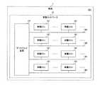
図1は、本発明の実施の形態に係る車載通信システムの構成を示す図である。[Configuration and basic operation]
FIG. 1 is a diagram showing a configuration of an in-vehicle communication system according to an embodiment of the present invention.
図1を参照して、車載通信システム301は、ゲートウェイ装置(検知装置)101と、複数の車載ECU(Electronic Control Unit)121とを備える。 With reference to FIG. 1, the vehicle-mounted
車載通信システム301は、車両1に搭載される。車載ネットワーク12は、車両1の内部における車載装置の一例である、複数の車載ECU121およびゲートウェイ装置101を含む。 The in-
ゲートウェイ装置101には、バス13A,13B,13C,13Dが接続される。以下、バス13A,13B,13C,13Dの各々を、バス13とも称する。
なお、ゲートウェイ装置101には、4つのバス13が接続される構成に限らず、3つ以下または5つ以上のバス13が接続されてもよい。 The
バス13には、たとえば複数の車載ECU121が接続される。バス13は、たとえば、非特許文献1(ルネサス エレクトロニクス株式会社、”CAN入門書 Rev. 1.00”、[online]、[平成29年6月17日検索]、インターネット〈URL:https://www.renesas.com/ja−jp/doc/products/mpumcu/apn/003/rjj05b0937_canap.pdf〉)に記載のCAN(Controller Area Network)(登録商標)の規格に従うバスである。 For example, a plurality of vehicle-mounted
なお、バス13には、複数の車載ECU121が接続される構成に限らず、1つの車載ECU121が接続される構成であってもよい。また、バス13は、FlexRay(登録商標)、MOST(Media Oriented Systems Transport)(登録商標)、イーサネット(登録商標)、およびLIN(Local Interconnect Network)等の規格に従うバスであってもよい。 The
車載ECU121は、たとえば、TCU(Telematics Communication Unit)、自動運転ECU、エンジンECU、センサ、ナビゲーション装置、ヒューマンマシンインタフェース、およびカメラ等である。 The in-
ゲートウェイ装置101は、バス13を介して車載ECU121と通信を行うことが可能である。ゲートウェイ装置101は、車両1において、異なるバス13に接続された車載ECU121間でやり取りされる情報を中継する中継処理を行う。 The
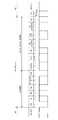
図2は、本発明の実施の形態に係る車載通信システムにおける車載ネットワークにおいて伝送されるデータフレームの一例を示す図である。図2には、標準フォーマットのデータフレームが示される。 FIG. 2 is a diagram showing an example of a data frame transmitted in an in-vehicle network in the in-vehicle communication system according to the embodiment of the present invention. FIG. 2 shows a standard format data frame.
図2を参照して、バス13において、データフレームは、インターフレームスペースIFS間において伝送される。 With reference to FIG. 2, on
データフレームは、先頭から、SOF(Start Of Frame)、ID(Identifier)、RTR(Remote Transmission Request)、CONTROL、DATA、CRC(Cyclic Redundancy Check)、CRC DELIMITER、ACK SLOT、ACK DELIMITERおよびEOF(End Of Frame)の領域を有する。 From the beginning, the data frames are SOF (Start Of Frame), ID (Identifier), RTR (Remote Transfer Request), CONTROL, DATA, CRC (Cyclic Redundancy Check), CRC DELIMITER, ACKS. It has a frame) region.
領域は、対応のビット数の長さを有する。また、各領域におけるビットのレベルは、レセシブ固定、ドミナント固定、ならびにレセシブおよびドミナントの可変のうちのいずれか1つである。 The region has a corresponding bit length. Also, the bit level in each region is one of responsive fixed, dominant fixed, and responsive and dominant variable.
具体的には、SOF領域は、1ビットの長さを有する。SOF領域における1ビットのレベルは、ドミナント固定である。 Specifically, the SOF region has a length of 1 bit. The 1-bit level in the SOF region is dominantly fixed.
ID領域は、11ビットの長さを有する。ID領域における11個のビットは、レセシブおよびドミナントの可変である。 The ID area has a length of 11 bits. The 11 bits in the ID region are recessive and dominant variable.
ID領域における11個のビットの示す値(以下、CAN−IDとも称する。)は、識別情報の一例であり、データフレームの差出元および宛先を認識可能である。 The value indicated by the 11 bits in the ID area (hereinafter, also referred to as CAN-ID) is an example of the identification information, and the source and destination of the data frame can be recognized.
また、CAN−IDは、たとえば、データフレームに含まれるデータの種類を示す。 Further, the CAN-ID indicates, for example, the type of data included in the data frame.
車載ネットワーク12におけるバス13において、互いに異なるCAN−IDを含む複数のデータフレームが伝送される。 A plurality of data frames including CAN-IDs different from each other are transmitted on the
車載ネットワーク12では、データフレームの送信は、たとえばブロードキャストにより行われる。たとえば、バス13に接続されたある車載装置が、送信ノードとして、予め設定されたCAN−IDを含むデータフレームをブロードキャストした場合、当該バス13に接続された他の車載装置は受信ノードとして動作し、ブロードキャストされたデータフレームを受信する。 In the in-
この際、受信ノードは、受信したデータフレームに含まれるCAN−IDに基づいて、受信したデータフレームが自己にとって必要であるか否かを判断する。 At this time, the receiving node determines whether or not the received data frame is necessary for itself based on the CAN-ID included in the received data frame.
車載ネットワーク12では、1つの受信ノードが、受信したデータフレームを自己にとって必要であると判断することもあるし、複数の受信ノードが、受信したデータフレームを自己にとって必要であると判断することもある。 In the in-
上記のように、車載ネットワーク12では、データフレームに含まれるCAN−IDに基づいて、当該データフレームの差出元および宛先を特定することが可能である。 As described above, in the vehicle-mounted
また、CAN−IDは、たとえば、通信調停の優先順位に用いられる。 In addition, CAN-ID is used, for example, as a priority for communication mediation.
バス13では、CAMA/CA(Carrier Sense Multiple Access with Collision Avoidance)方式に従って、最初にデータフレームを送信した車載ECU121が送信権を獲得する。 On the
たとえば、2つ以上の車載ECU121がほぼ同時にデータフレームの送信を開始した場合、ID領域の1ビット目から調停を行い、ドミナントレベルを最も長く連続して送信した車載ECU121がデータフレームの送信を行うことができる。調停の敗者となった車載ECU121は、データフレームの送信を停止し、受信動作を開始する。 For example, when two or more in-
車載ネットワーク12では、レセシブレベルおよびドミナントレベルは、それぞれ論理値1および論理値ゼロに対応するので、より小さいCAN−IDを含むデータフレームが優先的に伝送される。 In the in-
図3は、本発明の実施の形態に係る車載通信システムにおける車載ネットワークにおいて伝送されるデータフレームの一例を示す図である。図3には、拡張フォーマットのデータフレームが示される。 FIG. 3 is a diagram showing an example of a data frame transmitted in an in-vehicle network in the in-vehicle communication system according to the embodiment of the present invention. FIG. 3 shows an extended format data frame.
図3を参照して、拡張フォーマットのデータフレームでは、図2に示す標準フォーマットのデータフレームと比べて、ID領域とRTR領域との間において、SRR(Substitute Remote Request)、IDE(Identifier Extension)およびEXTENDED IDの領域がさらに設けられる。 With reference to FIG. 3, in the extended format data frame, the SRR (Substation Remote Request), IDE (Identifier Extension) and IDE (Identifier Extension) and between the ID area and the RTR area are compared with the standard format data frame shown in FIG. An area of EXTENDED ID is further provided.
[バスオフ攻撃]
図4は、本発明の実施の形態に係る車載通信システムにおけるトランシーバの状態遷移の一例を示す図である。[Bus off attack]
FIG. 4 is a diagram showing an example of state transition of the transceiver in the in-vehicle communication system according to the embodiment of the present invention.
図4を参照して、バス13を介して通信するゲートウェイ装置101および車載ECU121には、トランシーバが設けられる。トランシーバは、送信エラーカウンタTECおよび受信エラーカウンタRECを有する。 With reference to FIG. 4, a transceiver is provided in the
トランシーバは、CANの通信規格に従って動作し、エラーアクティブ状態、エラーパッシブ状態およびバスオフ状態のいずれか1つの状態をとる。 The transceiver operates according to the CAN communication standard and takes one of an error active state, an error passive state, and a bus-off state.
エラーアクティブ状態は、バス13上の通信に正常に参加することができる状態である。エラーパッシブ状態は、エラーを起こしやすい状態である。バスオフ状態は、バス13上の通信に参加できない状態であり、すべての通信が禁止される。 The error active state is a state in which the communication on the
エラーアクティブ状態またはエラーパッシブ状態にあるトランシーバは、エラーを検出した場合、エラーを検出したことを示すエラーフレームをバス13へ送信する。また、当該トランシーバは、たとえば、ID毎プロトコルエラー監視区間(図2および図3参照)におけるデータの送信中にエラーを検出した場合、データフレームの送信を中断することもある。 When the transceiver in the error active state or the error passive state detects an error, it sends an error frame indicating that the error has been detected to the
また、トランシーバは、自己が送信ユニットとして動作するときにエラーを検出した場合、送信エラーカウンタTECのカウント値を、検出したエラーの内容に応じて増加させる。 Further, when the transceiver detects an error when it operates as a transmission unit, the transceiver increases the count value of the transmission error counter TEC according to the content of the detected error.
また、トランシーバは、自己が受信ユニットとして動作するときにエラーを検出した場合、受信エラーカウンタRECのカウント値を、検出したエラーの内容に応じて増加させる。 Further, when the transceiver detects an error when it operates as a receiving unit, the transceiver increases the count value of the receiving error counter REC according to the content of the detected error.
また、トランシーバは、自己が送信ユニットとして動作するときにエラーを検出せずにメッセージを送信できた場合、送信エラーカウンタTECのカウント値をデクリメントする。 In addition, the transceiver decrements the count value of the transmission error counter TEC if it can transmit a message without detecting an error when it operates as a transmission unit.
また、トランシーバは、自己が受信ユニットとして動作するときにエラーを検出せずにメッセージを受信できた場合、受信エラーカウンタRECのカウント値をデクリメントする。 In addition, the transceiver decrements the count value of the reception error counter REC when it can receive a message without detecting an error when it operates as a reception unit.
トランシーバは、たとえば、起動されると初期状態を経てエラーアクティブ状態になる。 When a transceiver is started, for example, it goes through an initial state and then goes into an error active state.
エラーアクティブ状態にあるトランシーバは、送信エラーカウンタTECのカウント値または受信エラーカウンタRECのカウント値が127より大きい値になると、エラーパッシブ状態へ遷移する。 The transceiver in the error active state transitions to the error passive state when the count value of the transmission error counter TEC or the count value of the reception error counter REC becomes greater than 127.
エラーパッシブ状態にあるトランシーバは、送信エラーカウンタTECのカウント値および受信エラーカウンタRECのカウント値の両方が128より小さい値になると、エラーアクティブ状態へ遷移する。 The transceiver in the error passive state transitions to the error active state when both the count value of the transmission error counter TEC and the count value of the reception error counter REC are less than 128.
また、エラーパッシブ状態にあるトランシーバは、送信エラーカウンタTECのカウント値が255より大きい値になると、バスオフ状態へ遷移する。 Further, the transceiver in the error passive state transitions to the bus-off state when the count value of the transmission error counter TEC becomes larger than 255.
バスオフ状態にあるトランシーバは、連続する11ビットのレセシブビットを128回バス13上において検出した場合、送信エラーカウンタTECのカウント値および受信エラーカウンタRECのカウント値の両方をゼロにリセットするとともに、エラーアクティブ状態へ遷移する。 When the transceiver in the bus-off state detects consecutive 11-bit recessive bits on the
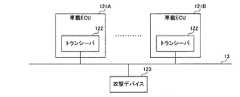
図5は、本発明の実施の形態に係る車載ネットワークにおける攻撃を説明するための図である。 FIG. 5 is a diagram for explaining an attack in an in-vehicle network according to an embodiment of the present invention.
図5を参照して、バス13には、車載ECU121である車載ECU121A,121Bと、攻撃デバイス123とが接続されている。車載ECU121A,121Bは、トランシーバ122を含む。 With reference to FIG. 5, the vehicle-mounted
バスオフ攻撃は、たとえば、非特許文献2(K. Cho、外1名、「Error Handling of In−vehicle Networks Makes Them Vulnerable」、CCS ’16 Proceedings of the 2016 ACM SIGSAC Conference on Computer and Communications Security、P.1044−1055)および非特許文献3(亀岡 良太、外5名、「ラズベリーパイからのスタッフエラー注入によるCAN ECUへのバスオフ攻撃」、2017 Symposium on Cryptography and Information Security、1E2−2)に記載されている。 The bus-off attack is, for example, Non-Patent Document 2 (K. Cho, one outsider, "Error Handling of In-Vehicle Information Makes Theme Vulnerable", CCS '16 Proceeding's of the 2016 ACM Computer Circuit 1044-155) and Non-Patent Document 3 (Ryota Kameoka, 5 outsiders, "Bus-off attack on CAN ECU by injecting staff error from raspberry pie", 2017 Computer on Cryptography and Information Security, 1E2-2). There is.
バスオフ攻撃では、攻撃デバイス123は、攻撃対象の車載ECU121におけるトランシーバ122の自己検査機能を攻撃することにより当該トランシーバ122の送信品質が低下したと誤認識させ、攻撃対象の車載ECU121をバス13から離脱させる。この結果、攻撃を受けた車載ECU121は、通信不能に追い込まれる。 In the bus-off attack, the
より詳細には、トランシーバ122は、たとえば、データフレームを送信する際に受信も同時に行うことにより、バス13へ送信したデータと同じデータがバス13から受信されたか否かを確認する。 More specifically, the
トランシーバ122は、バス13へ送信したデータと同じデータがバス13から受信された場合、送信が正常に行われたと判断する。一方、トランシーバ122は、バス13へ送信したデータと異なるデータがバス13から受信された場合、送信においてエラーが発生したと判断する。 When the
より詳細には、攻撃デバイス123は、たとえば、車載ECU121Bを攻撃する場合、ID毎プロトコルエラー監視区間(図2および図3参照)において、車載ECU121Bが送信するレセシブビットをドミナントビットで上書きする。 More specifically, when attacking the vehicle-mounted
これにより、車載ECU121Bにおけるトランシーバ122は、レセシブビットを送信したにも関わらずドミナントビットを受信したため送信においてエラーが発生したと判断し、送信エラーカウンタTECのカウント値を増加させる。 As a result, the
攻撃デバイス123がこの攻撃を繰り返すことにより、車載ECU121Bのトランシーバ122における送信エラーカウンタTECのカウント値はさらに増加する。当該送信エラーカウンタTECのカウント値が255より大きくなると、車載ECU121Bにおけるトランシーバ122はバスオフ状態に遷移し、トランシーバ122は、バス13上の通信に参加できなくなってしまう。 As the
[電気的データ改ざん攻撃]
図6は、本発明の実施の形態に係る車載ネットワークにおける電気的データ改ざん攻撃を説明するための図である。[Electrical data tampering attack]
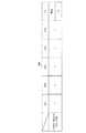
FIG. 6 is a diagram for explaining an electrical data falsification attack in an in-vehicle network according to an embodiment of the present invention.
図6を参照して、図2および図3に示すデータフレームにおける1ビットの期間には、シンクロナイゼーションセグメントSS、プロパゲーションタイムセグメントPTS、フェーズバッファセグメントPBS1およびフェーズバッファセグメントPBS2が含まれる。 With reference to FIG. 6, the 1-bit period in the data frame shown in FIGS. 2 and 3 includes the synchronization segment SS, the propagation time segment PTS, the phase buffer segment PBS1 and the phase buffer segment PBS2.
各セグメントは、Tq(Time quantum)という最小時間単位で構成される。SSのTq数は、1に固定である。PTS、PBS1およびPBS2のTq数は、所定の範囲内で任意の値に設定可能である。 Each segment is composed of a minimum time unit called Tq (Time Quantum). The Tq number of SS is fixed at 1. The Tq number of PTS, PBS1 and PBS2 can be set to any value within a predetermined range.
また、サンプルタイミングSPは、PBS1とPBS2との間に設けられる。車載ネットワーク12において、PTS、PBS1およびPBS2のTq数は車載ECU121ごとに様々な値に設定されるので、車載ネットワーク12における各車載ECU121のサンプルタイミングSPは、一般にばらついている。 Further, the sample timing SP is provided between PBS1 and PBS2. In the vehicle-mounted
電気的データ改ざん攻撃は、たとえば、非特許文献4(中山 淑文、外3名、「車載CANバスにおける電気的データ改竄の効果」、2017 Symposium on Cryptography and Information Security、1E2−3)に記載されている。 The electrical data falsification attack is described in, for example, Non-Patent Document 4 (Yoshifumi Nakayama, 3 outsiders, "Effect of Electrical Data Falsification on In-Vehicle CAN Bus", 2017 Symposium on Cryptography and Information Security, 1E2-3). There is.
電気的データ改ざん攻撃では、送信ユニットのサンプリングポイントSPより遅いサンプリングポイントSPを有する受信ユニットに対して攻撃が行われる。 In the electrical data tampering attack, the attack is performed on the receiving unit having a sampling point SP slower than the sampling point SP of the transmitting unit.
たとえば、図5において、車載ECU121Bにおけるトランシーバ122および車載ECU121Aにおけるトランシーバ122がそれぞれ送信ユニットおよび受信ユニットとして動作する状況を想定する。 For example, in FIG. 5, it is assumed that the
この例では、送信ユニットにおけるサンプルタイミングSPがビットの先頭から4Tq目であり、また受信ユニットにおけるサンプルタイミングSPがビットの先頭から6Tq目である。 In this example, the sample timing SP in the transmitting unit is the 4th Tqth from the beginning of the bit, and the sample timing SP in the receiving unit is the 6Tqth from the beginning of the bit.
攻撃デバイス123は、送信ユニットのサンプリングポイントSPでは改ざんせずに、受信ユニットのサンプリングポイントSPにおいてデータ改ざん用の電気信号をバス13へ送信することで、送信ユニットからのデータを改ざんする。これにより、送信ユニットにおけるビットエラー検出を回避しつつ受信ユニットが受信するデータを改ざんすることが可能となる。 The
より詳細には、攻撃デバイス123は、送信ユニットがデータビットを送信する場合において、ビットの先頭から4Tq目が経過してから6Tq目に至るまでに、当該データビットを改ざんするための電気信号をバス13へ送信する。 More specifically, when the transmitting unit transmits a data bit, the
送信ユニットは、自己が送信したデータビットを4Tq目のサンプルタイミングで取得するので、正常に送信したと判断する。 Since the transmission unit acquires the data bit transmitted by itself at the sample timing of the 4th Tq, it determines that the data bit has been transmitted normally.
一方、受信ユニットは、攻撃デバイス123によって改ざんされた不正なデータビットを6Tq目に取得してしまう。 On the other hand, the receiving unit acquires an invalid data bit tampered with by the
このような電気的データ改ざん攻撃では、送信ユニットおよび受信ユニットの両方においてエラーが検出されない。 In such an electrical data tampering attack, no error is detected in both the transmitting unit and the receiving unit.
しかしながら、上述したように、各車載ECU121のサンプルタイミングSPがばらついているので、車載ネットワーク12におけるすべての車載ECU121においてエラーを検出させずに電気的データ改ざん攻撃を行うことは困難であると考えられる。 However, as described above, since the sample timing SP of each in-
したがって、一般に、車載ネットワーク12における一部の車載ECU121が、電気的データ改ざん攻撃を検出してエラーフレームをバス13へ送信する状況となる。 Therefore, in general, a part of the vehicle-mounted
このような、バスオフ攻撃および電気的データ改ざん攻撃等の車載ネットワーク12における攻撃をより精度よく検知するための技術が求められる。 There is a need for a technique for more accurately detecting attacks in the in-
そこで、本発明の実施の形態に係るゲートウェイ装置では、以下のような構成および動作により、このような課題を解決する。 Therefore, the gateway device according to the embodiment of the present invention solves such a problem by the following configuration and operation.
[ゲートウェイ装置101の構成]
図7は、本発明の実施の形態に係る車載通信システムにおけるゲートウェイ装置の構成を示す図である。[Configuration of gateway device 101]
FIG. 7 is a diagram showing a configuration of a gateway device in an in-vehicle communication system according to an embodiment of the present invention.
図7を参照して、ゲートウェイ装置101は、送受信部(監視部)51A,51B,51C,51Dと、中継部52と、集計部54と、検知部55と、記憶部56とを備える。以下、送受信部51A,51B,51C,51Dの各々を、送受信部51とも称する。 With reference to FIG. 7, the
なお、ゲートウェイ装置101は、4つの送受信部51を備える構成に限らず、3つ以下、または5つ以上の送受信部51を備える構成であってもよい。 The
ゲートウェイ装置101は、検知装置として機能し、識別情報を含むデータフレームが伝送されるバス13を含む車載ネットワーク12における攻撃を検知する。 The
より詳細には、ゲートウェイ装置101における送受信部51は、たとえば、トランシーバであり、バス13に接続される。具体的には、送受信部51A,51B,51C,51Dは、それぞれバス13A,13B,13C,13Dに接続される。 More specifically, the transmission / reception unit 51 in the
送受信部51は、自己の接続されたバス13からデータフレームを受信すると、ID監視区間において受信した各ビットのレベルからCAN−IDを取得する(図2および図3参照)。 When the transmission / reception unit 51 receives a data frame from the
送受信部51は、取得したCAN−IDに基づいて、受信したデータフレームが中継を要するフレームであるか否かを判断する。 The transmission / reception unit 51 determines whether or not the received data frame is a frame that requires relay based on the acquired CAN-ID.
送受信部51は、受信したデータフレームが中継を要するフレームであると判断した場合、当該データフレームを中継部52へ出力する。 When the transmission / reception unit 51 determines that the received data frame is a frame that requires relay, the transmission / reception unit 51 outputs the data frame to the
中継部52は、データフレームの中継処理を行う。具体的には、中継部52は、たとえば、送受信部51Aからデータフレームを受けると、受けたデータフレームに含まれるCAN−IDに基づいて、当該データフレームを出力すべき送受信部51を特定する。 The
より詳細には、中継部52は、たとえば、CAN−IDと送受信部51との対応関係を示すテーブルを有している。この例では、中継部52は、当該対応関係に基づいて、当該CAN−IDに対応する送受信部51として送受信部51Bを特定する。そして、中継部52は、上記データフレームを送受信部51Bへ出力する。 More specifically, the
送受信部51Bは、中継部52からデータフレームを受けると、受けたデータフレームをバス13Bへ送信する。 When the transmission /
また、送受信部51は、バス13における通信エラーを監視する。より詳細には、送受信部51は、ID監視区間においてCAN−IDを取得した後、ID毎プロトコルエラー監視区間におけるビット列を監視する。 Further, the transmission / reception unit 51 monitors a communication error on the
送受信部51は、たとえば、差出元の車載ECU121によるデータフレームの送信の中断を検出した場合、およびエラーフレームを受信した場合、通信エラーが発生したと判断する。 The transmission / reception unit 51 determines that a communication error has occurred, for example, when the transmission source vehicle-mounted
そして、送受信部51は、通信エラーが発生したと判断したデータフレームのCAN−IDを集計部54へ通知する。 Then, the transmission / reception unit 51 notifies the
図8は、本発明の実施の形態に係るゲートウェイ装置において用いられる長監視間隔期間および短監視間隔期間の一例を示す図である。なお、図8において、横軸は時間を示す。 FIG. 8 is a diagram showing an example of a long monitoring interval period and a short monitoring interval period used in the gateway device according to the embodiment of the present invention. In FIG. 8, the horizontal axis represents time.
図8を参照して、集計部54は、送受信部51の監視結果に基づいて、識別情報ごとの通信エラーの発生状況を集計する。 With reference to FIG. 8, the
より詳細には、集計部54は、たとえば、短監視間隔期間ST1,ST2,ST3,ST4,ST5を含む長監視間隔期間LTを設定する。短監視間隔期間ST1〜ST5は、連続している。以下、短監視間隔期間ST1,ST2,ST3,ST4,ST5の各々を、短監視間隔期間STとも称する。 More specifically, the
なお、集計部54は、5つの短監視間隔期間STを含む長監視間隔期間LTを設定する構成に限らず、2つ、3つ、4つまたは6つ以上の短監視間隔期間STを含む長監視間隔期間LTを設定してもよい。 The
図9は、本発明の実施の形態に係るゲートウェイ装置における集計部が作成する集計表の一例を示す図である。 FIG. 9 is a diagram showing an example of a tabulation table created by the tabulation unit in the gateway device according to the embodiment of the present invention.
図9を参照して、集計部54は、たとえば、短監視間隔期間STの各々における通信エラーの発生回数の合計値、および長監視間隔期間LTにおける通信エラーの発生回数の合計値を含む集計表Tbl1を送受信部51ごとに作成して保持する。図9に示す集計表Tbl1は、たとえば、送受信部51A用の集計表である。 With reference to FIG. 9, the
集計表Tbl1では、車載ネットワーク12において用いられるCAN−ID数分の行が設けられ、各行には、短監視間隔期間ST1〜ST5および長監視間隔期間LTにそれぞれ対応するフィールドが設けられる。 In the summary table Tbl1, rows corresponding to the number of CAN-IDs used in the in-
集計部54は、送受信部51AからCAN−IDの通知を受けるごとに、以下の処理を行う。 The totaling
すなわち、集計部54は、集計表Tbl1において、通知されたCAN−IDに対応する行において、通知を受けたタイミングを含む短監視間隔期間STに対応するフィールドにおけるプロトコルエラー発生回数をインクリメントする。 That is, the
具体的には、集計部54は、たとえば、短監視間隔期間ST1において、送受信部51AからCAN−IDとして「1」の通知を受けると、CAN−IDが「1」の行において、短監視間隔期間ST1に対応するフィールドにおけるプロトコルエラー発生回数をインクリメントする。 Specifically, for example, in the short monitoring interval period ST1, when the
集計部54がこのような処理を行うことにより、短監視間隔期間ST1が満了すると、CAN−IDが「1」、「2」および「N」の行において、短監視間隔期間ST1に対応するフィールドにおけるプロトコルエラー発生回数としてそれぞれ5回、5回およびゼロ回が集計表Tbl1に記録される。 When the short monitoring interval period ST1 expires as a result of the
集計部54は、短監視間隔期間ST2〜短監視間隔期間ST5においても、同様の処理を行う。 The
そして、集計部54は、長監視間隔期間LTが満了すると、長監視間隔期間LTにおけるCAN−IDごとのプロトコルエラー発生回数を集計表Tbl1に書き込む。 Then, when the long monitoring interval period LT expires, the
より詳細には、集計部54は、短監視間隔期間ST1〜ST5におけるプロトコルエラー発生回数の合計値をCAN−IDごとに算出する。 More specifically, the
集計部54は、CAN−IDごとに、算出した合計値を、当該CAN−IDの行において長監視間隔期間LTに対応するフィールドに書き込む。 The
具体的には、集計部54は、たとえば、CAN−IDが「1」の行において、短監視間隔期間ST1〜ST5におけるプロトコルエラー発生回数の合計値として50回を算出する。 Specifically, the
集計部54は、算出した50回を、CAN−IDが「1」の行において長監視間隔期間LTに対応するフィールドに書き込む。 The
図10は、本発明の実施の形態に係るゲートウェイ装置における集計部が作成する集計表の一例を示す図である。 FIG. 10 is a diagram showing an example of a tabulation table created by the tabulation unit in the gateway device according to the embodiment of the present invention.
図10を参照して、集計部54は、たとえば、各短監視間隔期間STにおけるバス内プロトコルエラー分布、および長監視間隔期間LTにおけるバス内プロトコルエラー分布の平均を含む集計表Tbl2を送受信部51ごとに作成して保持する。図10に示す集計表Tbl2は、たとえば、送受信部51A用の集計表である。 With reference to FIG. 10, the
集計表Tbl2では、短監視間隔期間ST1〜ST5および長監視間隔期間LTにそれぞれ対応するフィールドが設けられる。 In the summary table Tbl2, fields corresponding to the short monitoring interval period ST1 to ST5 and the long monitoring interval period LT are provided.
集計部54は、短監視間隔期間STが満了すると、当該短監視間隔期間STにおけるバス内プロトコルエラー分布を算出し、算出したバス内プロトコルエラー分布を当該短監視間隔期間STに対応するフィールドに書き込む。 When the short monitoring interval period ST expires, the
ここで、バス内プロトコルエラー分布は、通信エラーの発生した識別情報の数であるエラーID数の一例である。具体的には、バス内プロトコルエラー分布は、短監視間隔期間STにおいて、プロトコルエラー発生回数が1回以上となったCAN−IDの個数である。 Here, the protocol error distribution in the bus is an example of the number of error IDs, which is the number of identification information in which a communication error has occurred. Specifically, the protocol error distribution in the bus is the number of CAN-IDs in which the number of protocol error occurrences is one or more in the short monitoring interval period ST.
具体的には、集計部54は、たとえば、短監視間隔期間ST1が満了すると、短監視間隔期間ST1において、プロトコルエラー発生回数が1回以上のCAN−IDが「1」および「2」であることから、バス内プロトコルエラー分布として2を算出する。 Specifically, for example, when the short monitoring interval period ST1 expires, the
そして、集計部54は、算出した2を当該短監視間隔期間ST1に対応するフィールドに書き込む。 Then, the
集計部54は、短監視間隔期間ST2〜短監視間隔期間ST5の各々が満了した場合においても、同様の処理を行う。 The
そして、集計部54は、長監視間隔期間LTが満了すると、長監視間隔期間LTにおけるバス内プロトコルエラー分布の平均を長監視間隔期間LTに対応するフィールドに書き込む。 Then, when the long monitoring interval period LT expires, the
具体的には、集計部54は、短監視間隔期間ST1〜ST5における各バス内プロトコルエラー分布の平均として、(2+2+1+1+1)を5で除した値である1.4を算出する。 Specifically, the
集計部54は、算出した1.4を長監視間隔期間LTに対応するフィールドに書き込む。 The
再び図7を参照して、検知部55は、集計部54の集計結果に基づいて車載ネットワーク12における攻撃を検知する。 With reference to FIG. 7 again, the
詳細には、検知部55は、たとえば、集計結果における各CAN−ID間での通信エラーの発生状況の偏りに基づいて車載ネットワーク12における攻撃を検知する。 Specifically, the
より詳細には、検知部55は、たとえば、通信エラーの発生回数のCAN−IDごとの合計、およびバス内プロトコルエラー分布に基づいて車載ネットワーク12における攻撃を検知する。 More specifically, the
検知部55は、たとえば、短監視間隔ごとに短間隔検知処理を行う。具体的には、検知部55は、たとえば、短監視間隔期間STにおける通信エラーの発生回数のCAN−IDごとの合計としきい値Th1との比較結果Rst1、バス内プロトコルエラー分布としきい値Th2との比較結果Rst2、およびバス内プロトコルエラー分布としきい値Th2より大きいしきい値Th5との比較結果Rst5に基づいて車載ネットワーク12における攻撃を検知する。 The
より具体的には、検知部55は、たとえば、集計部54によって設定された短監視間隔期間ST1,ST2,ST3,ST4,ST5および長監視間隔期間LTに従って動作し、短監視間隔期間ST1が満了すると、以下の処理を行う。 More specifically, the
すなわち、検知部55は、短監視間隔期間ST1におけるプロトコルエラー発生回数のCAN−IDごとの合計値を、集計部54が保持する集計表Tbl1(図9参照)から取得する。 That is, the
また、検知部55は、短監視間隔期間ST1におけるバス内プロトコルエラー分布を、集計部54が保持する集計表Tbl2(図10参照)から取得する。 Further, the
検知部55は、たとえば、「1」〜「N」のCAN−IDの中から昇順にCAN−IDを1つずつ選択し、選択したCAN−IDに対応するプロトコルエラー発生回数を用いた評価を行う。 For example, the
具体的には、検知部55は、たとえば、選択したCAN−ID(以下、対象CAN−IDとも称する。)に対応するプロトコルエラー発生回数の合計がしきい値Th1より大きく、かつバス内プロトコルエラー分布がしきい値Th2より小さい場合、少数の車載ECU121に対するサイバー攻撃である少数攻撃が発生したと判断する。検知部55は、判断結果をログとして記憶部56に記録する。 Specifically, in the
たとえば、1〜2個の車載ECU121に対してサイバー攻撃があった場合、サイバー攻撃された車載ECU121が差出元または宛先となるデータフレームに含まれるCAN−IDについてのプロトコルエラー発生回数は大きくなる。一方、サイバー攻撃された車載ECU121を差出元または宛先として示すCAN−IDの個数は少数であるため、バス内プロトコルエラー分布は大きくならない。上記の構成により、検知部55は、少数攻撃が発生したことをより正しく判断することができる。 For example, when there is a cyber attack on one or two vehicle-mounted
また、検知部55は、たとえば、対象CAN−IDに対応するプロトコルエラー発生回数の合計がしきい値Th1より大きく、かつバス内プロトコルエラー分布がしきい値Th5より大きい場合、多数の車載ECU121に対するサイバー攻撃である多数攻撃が発生したと判断する。検知部55は、判断結果をログとして記憶部56に記録する。 Further, for example, when the total number of protocol error occurrences corresponding to the target CAN-ID is larger than the threshold value Th1 and the protocol error distribution in the bus is larger than the threshold value Th5, the
たとえば、多数の車載ECU121に対してサイバー攻撃があった場合、サイバー攻撃された車載ECU121が差出元または宛先となるデータフレームに含まれるCAN−IDについてのプロトコルエラー発生回数は大きくなる。また、サイバー攻撃された車載ECU121を差出元または宛先として示すCAN−IDの個数も多数であるため、バス内プロトコルエラー分布が極めて大きくなる。上記の構成により、検知部55は、多数攻撃が発生したことをより正しく判断することができる。 For example, when there is a cyber attack on a large number of vehicle-mounted
また、検知部55は、たとえば、対象CAN−IDに対応するプロトコルエラー発生回数の合計がしきい値Th1以下であるか、またはバス内プロトコルエラー分布がしきい値Th2以上でありかつしきい値Th5以下である場合、ノイズまたは車載ECU121の故障等による通信エラーが発生したと判断する。この場合、検知部55は、判断結果を記憶部56に記録しない。 Further, in the
たとえば、ノイズはランダムに発生することが多いので、通信エラーの発生するデータフレームもランダムとなる。このため、バス内プロトコルエラー分布は大きくなる。また、車載ECU121が経年劣化する場合、車載ECU121が差出元または宛先となるデータフレームの通信エラーが散発的に発生すると考えられる。このため、バス内プロトコルエラー分布が小さくても、車載ECU121が差出元または宛先となるデータフレームに含まれるCAN−IDについてのプロトコルエラー発生回数も小さくなる。上記の構成により、検知部55は、少数攻撃または多数攻撃の発生を誤って判断してしまうことを防ぐことができる。 For example, since noise is often generated randomly, the data frame in which a communication error occurs is also random. Therefore, the protocol error distribution in the bus becomes large. Further, when the in-
検知部55は、たとえば、集計部54によって設定された短監視間隔期間ST2,ST3,ST4,ST5が満了した場合の各々においても、短監視間隔期間ST1が満了した場合と同様に、短間隔検知処理を行う。 For example, in each of the cases where the short monitoring interval period ST2, ST3, ST4, and ST5 set by the
また、検知部55は、たとえば、長監視間隔ごとに長間隔検知処理を行う。具体的には、検知部55は、たとえば、長監視間隔期間LTにおける通信エラーの発生回数のCAN−IDごとの合計としきい値Th3との比較結果Rst3、バス内プロトコルエラー分布の平均としきい値Th4との比較結果Rst4、および当該平均としきい値Th4より大きいしきい値Th6との比較結果Rst6に基づいて車載ネットワーク12における攻撃を検知する。 Further, the
より具体的には、検知部55は、長監視間隔期間LTが満了すると、長監視間隔期間LTにおけるプロトコルエラー発生回数のCAN−IDごとの合計値を、集計部54が保持する集計表Tbl1(図9参照)から取得する。 More specifically, when the long monitoring interval period LT expires, the
また、検知部55は、長監視間隔期間LTにおけるバス内プロトコルエラー分布の平均を、集計部54が保持する集計表Tbl2(図10参照)から取得する。 Further, the
検知部55は、たとえば、「1」〜「N」のCAN−IDの中から昇順にCAN−IDを1つずつ選択し、選択したCAN−IDに対応するプロトコルエラー発生回数を用いた評価を行う。 For example, the
具体的には、検知部55は、たとえば、選択したCAN−IDすなわち対象CAN−IDに対応するプロトコルエラー発生回数の合計がしきい値Th3より大きく、かつバス内プロトコルエラー分布の平均がしきい値Th4より小さい場合、少数攻撃が発生したと判断する。検知部55は、判断結果をログとして記憶部56に記録する。 Specifically, in the
たとえば、1〜2個の車載ECU121に対してサイバー攻撃があった場合、サイバー攻撃された車載ECU121が差出元または宛先となるデータフレームに含まれるCAN−IDについてのプロトコルエラー発生回数は大きくなる。一方、サイバー攻撃された車載ECU121を差出元または宛先として示すCAN−IDの個数は少数であるため、バス内プロトコルエラー分布の平均は大きくならない。上記の構成により、検知部55は、少数攻撃が発生したことをより正しく判断することができる。 For example, when there is a cyber attack on one or two vehicle-mounted
また、検知部55は、たとえば、対象CAN−IDに対応するプロトコルエラー発生回数の合計がしきい値Th3より大きく、かつバス内プロトコルエラー分布の平均がしきい値Th6より大きい場合、多数攻撃が発生したと判断する。検知部55は、判断結果をログとして記憶部56に記録する。 Further, for example, when the total number of protocol error occurrences corresponding to the target CAN-ID is larger than the threshold value Th3 and the average of the protocol error distribution in the bus is larger than the threshold value Th6, the
たとえば、多数の車載ECU121に対してサイバー攻撃があった場合、サイバー攻撃された車載ECU121が差出元または宛先となるデータフレームに含まれるCAN−IDについてのプロトコルエラー発生回数は大きくなる。また、サイバー攻撃された車載ECU121を差出元または宛先として示すCAN−IDの個数も多数であるため、バス内プロトコルエラー分布の平均が極めて大きくなる。上記の構成により、検知部55は、多数攻撃が発生したことをより正しく判断することができる。 For example, when there is a cyber attack on a large number of vehicle-mounted
また、検知部55は、たとえば、対象CAN−IDに対応するプロトコルエラー発生回数の合計がしきい値Th3以下であるか、またはバス内プロトコルエラー分布の平均がしきい値Th4以上でありかつしきい値Th6以下である場合、ノイズまたは車載ECU121の故障等による通信エラーが発生したと判断する。この場合、検知部55は、判断結果を記憶部56に記録しない。 Further, in the
たとえば、ノイズはランダムに発生することが多いので、通信エラーの発生するデータフレームもランダムとなる。このため、バス内プロトコルエラー分布の平均は大きくなる。また、車載ECU121が経年劣化する場合、車載ECU121が差出元または宛先となるデータフレームの通信エラーが散発的に発生すると考えられる。このため、バス内プロトコルエラー分布の平均が小さくても、車載ECU121が差出元または宛先となるデータフレームに含まれるCAN−IDについてのプロトコルエラー発生回数も小さくなる。上記の構成により、検知部55は、少数攻撃または多数攻撃の発生を誤って判断してしまうことを防ぐことができる。 For example, since noise is often generated randomly, the data frame in which a communication error occurs is also random. Therefore, the average of the protocol error distribution in the bus becomes large. Further, when the in-
[動作の流れ]
ゲートウェイ装置101は、コンピュータを備え、当該コンピュータにおけるCPU等の演算処理部は、以下に示すフローチャートの各ステップの一部または全部を含むプログラムを図示しないメモリから読み出して実行する。この装置のプログラムは、外部からインストールすることができる。この装置のプログラムは、記録媒体に格納された状態で流通する。[Operation flow]
The
図11は、本発明の実施の形態に係るゲートウェイ装置がサイバー攻撃を検知する際の動作手順を定めたフローチャートである。 FIG. 11 is a flowchart defining an operation procedure when the gateway device according to the embodiment of the present invention detects a cyber attack.
図11を参照して、まず、ゲートウェイ装置101は、短監視間隔期間STが満了するまで、データフレームの中継処理を行いながら、発生した通信エラーを記録する(ステップS102でNO)。 With reference to FIG. 11, first, the
そして、ゲートウェイ装置101は、短監視間隔期間STが満了すると(ステップS102でYES)、当該短監視間隔期間STにおいて発生した通信エラーを集計する(ステップS104)。 Then, when the short monitoring interval period ST expires (YES in step S102), the
次に、ゲートウェイ装置101は、車載ネットワーク12において用いられる複数のCAN−IDのうちの1つを選択する(ステップS106)。 Next, the
次に、ゲートウェイ装置101は、選択したCAN−IDすなわち対象CAN−IDに対応するプロトコルエラー発生回数の短監視間隔期間STにおける合計ENsがしきい値Th1より大きく、かつ当該短監視間隔期間STにおけるバス内プロトコルエラー分布EDsがしきい値Th2より小さい場合(ステップS108でYES)、少数攻撃を検知する(ステップS118)。 Next, in the
また、ゲートウェイ装置101は、合計ENsがしきい値Th1より大きく、かつバス内プロトコルエラー分布EDsがしきい値Th5より大きい場合(ステップS108でNOおよびステップS110でYES)、多数攻撃を検知する(ステップS112)。 Further, when the total ENs are larger than the threshold Th1 and the in-bus protocol error distribution EDs are larger than the threshold Th5 (NO in step S108 and YES in step S110), the
次に、ゲートウェイ装置101は、少数攻撃を検知するか(ステップS118)、または多数攻撃を検知すると(ステップS112)、検知結果をログに記録する(ステップS114)。 Next, when the
また、ゲートウェイ装置101は、合計ENsがしきい値Th1以下であるか、もしくはバス内プロトコルエラー分布EDsがしきい値Th2以上かつしきい値Th5以下である場合(ステップS108でNOおよびステップS110でNO)、または検知結果をログに記録すると(ステップS114)、車載ネットワーク12において用いられる複数のCAN−IDをすべて選択したか否かを確認する(ステップS116)。 Further, in the
ゲートウェイ装置101は、上記複数のCAN−IDの中で未選択のCAN−IDが存在する場合(ステップS116でNO)、上記複数のCAN−IDにおいて未選択のCAN−IDを1つ選択する(ステップS106)。 When there is an unselected CAN-ID among the plurality of CAN-IDs (NO in step S116), the
一方、ゲートウェイ装置101は、上記複数のCAN−IDをすべて選択した場合(ステップS116でYES)、新たな短監視間隔期間STが満了するまで、データフレームの中継処理を行いながら、発生した通信エラーを記録する(ステップS102でNO)。 On the other hand, when all of the plurality of CAN-IDs are selected (YES in step S116), the
図12は、本発明の実施の形態に係るゲートウェイ装置がサイバー攻撃を検知する際の動作手順を定めたフローチャートである。 FIG. 12 is a flowchart defining an operation procedure when the gateway device according to the embodiment of the present invention detects a cyber attack.
図12を参照して、まず、ゲートウェイ装置101は、長監視間隔期間LTが満了するまで、データフレームの中継処理を行いながら、長監視間隔期間LTに含まれる各短監視間隔期間STにおいて発生した通信エラーを記録する(ステップS202でNO)。 With reference to FIG. 12, first, the
そして、ゲートウェイ装置101は、長監視間隔期間LTが満了すると(ステップS202でYES)、当該各短監視間隔期間STにおいて発生した通信エラーを集計する(ステップS204)。 Then, when the long monitoring interval period LT expires (YES in step S202), the
次に、ゲートウェイ装置101は、車載ネットワーク12において用いられる複数のCAN−IDのうちの1つを選択する(ステップS206)。 Next, the
次に、ゲートウェイ装置101は、選択したCAN−IDすなわち対象CAN−IDに対応するプロトコルエラー発生回数の長監視間隔期間LTにおける合計ENpがしきい値Th3より大きく、かつ当該長監視間隔期間LTにおけるバス内プロトコルエラー分布EDpがしきい値Th4より小さい場合(ステップS208でYES)、少数攻撃を検知する(ステップS218)。 Next, in the
また、ゲートウェイ装置101は、合計ENpがしきい値Th3より大きく、かつバス内プロトコルエラー分布EDpがしきい値Th6より大きい場合(ステップS208でNOおよびステップS210でYES)、多数攻撃を検知する(ステップS212)。 Further, the
次に、ゲートウェイ装置101は、少数攻撃を検知するか(ステップS218)、または多数攻撃を検知すると(ステップS212)、検知結果をログに記録する(ステップS214)。 Next, when the
また、ゲートウェイ装置101は、合計ENpがしきい値Th3以下であるか、もしくはバス内プロトコルエラー分布EDpがしきい値Th4以上かつしきい値Th6以下である場合(ステップS208でNOおよびステップS210でNO)、または検知結果をログに記録すると(ステップS214)、車載ネットワーク12において用いられる複数のCAN−IDをすべて選択したか否かを確認する(ステップS216)。 Further, in the
ゲートウェイ装置101は、上記複数のCAN−IDの中で未選択のCAN−IDが存在する場合(ステップS216でNO)、上記複数のCAN−IDにおいて未選択のCAN−IDを1つ選択する(ステップS206)。 When the unselected CAN-ID exists among the plurality of CAN-IDs (NO in step S216), the
一方、ゲートウェイ装置101は、上記複数のCAN−IDをすべて選択した場合(ステップS216でYES)、新たな長監視間隔期間LTが満了するまで、データフレームの中継処理を行いながら、新たな長監視間隔期間LTにおいて発生した通信エラーを記録する(ステップS202でNO)。 On the other hand, when all of the plurality of CAN-IDs are selected (YES in step S216), the
なお、本発明の実施の形態に係るゲートウェイ装置は、バス13A〜13Dのすべてを攻撃の検知対象とする構成であるとしたが、これに限定するものではない。ゲートウェイ装置101は、バス13A〜13Dの一部を攻撃の検知対象とする構成であってもよい。 The gateway device according to the embodiment of the present invention is configured to detect all of the
また、本発明の実施の形態に係る車載ネットワークでは、ゲートウェイ装置101が、車載ネットワーク12における攻撃を検知する構成であるとしたが、これに限定するものではない。バス13に接続された各車載ECU121のうちの少なくともいずれか1つが、ゲートウェイ装置101と同様に、検知装置として動作し、対応のバス13における攻撃を検知する構成であってもよい。 Further, in the vehicle-mounted network according to the embodiment of the present invention, the
また、本発明の実施の形態に係る車載ネットワークでは、差出元および宛先の両方を認識可能な識別情報を含むデータフレームが伝送される構成であるとしたが、これに限定するものではない。差出元および宛先のいずれか一方を認識可能な識別情報を含むデータフレームが伝送される構成であってもよい。 Further, the in-vehicle network according to the embodiment of the present invention is configured to transmit a data frame including identification information that can recognize both the sender and the destination, but the present invention is not limited to this. A data frame containing identification information that can recognize either the sender or the destination may be transmitted.
また、本発明の実施の形態に係る車載ネットワークでは、差出元および宛先の両方を認識可能なCAN−IDを含むデータフレームが伝送される構成であるとしたが、これに限定するものではない。差出元および宛先の少なくともいずれか一方を直接示す識別情報、たとえばアドレスを含むデータフレームが伝送される構成であってもよい。 Further, the in-vehicle network according to the embodiment of the present invention is configured to transmit a data frame including a CAN-ID capable of recognizing both a sender and a destination, but the present invention is not limited to this. It may be configured to transmit identification information that directly indicates at least one of the sender and the destination, for example, a data frame including an address.
また、本発明の実施の形態に係るゲートウェイ装置では、検知部55は、集計部54における集計結果における各CAN−ID間での通信エラーの発生状況の偏りに基づいて車載ネットワーク12における攻撃を検知する構成であるとしたが、これに限定するものではない。検知部55は、上記偏りに基づかずに車載ネットワーク12における攻撃を検知する構成であってもよい。具体的には、検知部55は、たとえば、図10に示す集計表Tbl2を用いずに、車載ネットワーク12における攻撃を検知する。 Further, in the gateway device according to the embodiment of the present invention, the
また、本発明の実施の形態に係るゲートウェイ装置では、検知部55は、短間隔検知処理および長間隔検知処理の両方を行う構成であるとしたが、これに限定するものではない。検知部55は、短間隔検知処理および長間隔検知処理のいずれか一方を行う構成であってもよい。 Further, in the gateway device according to the embodiment of the present invention, the
また、本発明の実施の形態に係るゲートウェイ装置では、検知部55は、比較結果Rst1、比較結果Rst2および比較結果Rst5に基づいて車載ネットワーク12における攻撃を検知する構成であるとしたが、これに限定するものではない。検知部55は、比較結果Rst1および比較結果Rst2に基づいて車載ネットワーク12における攻撃を検知する構成であってもよい。 Further, in the gateway device according to the embodiment of the present invention, the
また、本発明の実施の形態に係るゲートウェイ装置では、検知部55は、比較結果Rst3、比較結果Rst4および比較結果Rst6に基づいて車載ネットワーク12における攻撃を検知する構成であるとしたが、これに限定するものではない。検知部55は、比較結果Rst3および比較結果Rst4に基づいて車載ネットワーク12における攻撃を検知する構成であってもよい。 Further, in the gateway device according to the embodiment of the present invention, the
ところで、特許文献1に記載の車載通信システムでは、車載ネットワークに限定して接続される第1のECUおよび第2のECUがメッセージ認証に用いる第1の暗号鍵と、車載ネットワークおよび車外ネットワークの両方に接続される第3のECUが用いる第2の暗号鍵とが異なることにより、車外ネットワークに接続されない第1のECUおよび第2のECUに対する車外ネットワークからのサイバー攻撃を防いでいる。 By the way, in the in-vehicle communication system described in
しかしながら、たとえば、各ECU間を接続するバスにおいて伝送される信号を電気的に操作するようなサイバー攻撃に対しては、上記のようなセキュリティ対策が無効化されることがある。 However, for example, the above security measures may be invalidated against a cyber attack in which a signal transmitted on a bus connecting each ECU is electrically operated.
このような攻撃を受けた場合において、車載ネットワークにおける攻撃を精度よく検知するための技術が求められる。 When such an attack is received, a technique for accurately detecting the attack in the in-vehicle network is required.
これに対して、本発明の実施の形態に係るゲートウェイ装置は、差出元および宛先の少なくともいずれか一方を認識可能な識別情報を含むデータフレームが伝送されるバス13を含む車載ネットワーク12における攻撃を検知する。バス13において、互いに異なる識別情報を含む複数のデータフレームが伝送される。送受信部51は、バス13における通信エラーを監視する。集計部54は、送受信部51の監視結果に基づいて、識別情報ごとの通信エラーの発生状況を集計する。そして、検知部55は、集計部54の集計結果に基づいて車載ネットワーク12における攻撃を検知する。 On the other hand, the gateway device according to the embodiment of the present invention attacks an attack on an in-
このような構成により、識別情報ごとの通信エラーの発生状況の集計結果に基づいて、データフレームの差出元または宛先の車載装置ごとの通信エラーの発生状況を認識することができるので、たとえば、バス13において伝送される信号を電気的に操作するようなサイバー攻撃を受けて通信エラーの発生した車載装置を、特定することができる。したがって、車載ネットワークにおける攻撃を精度よく検知することができる。 With such a configuration, it is possible to recognize the occurrence status of the communication error for each in-vehicle device of the source or destination of the data frame based on the aggregated result of the occurrence status of the communication error for each identification information. Therefore, for example, the bus. It is possible to identify an in-vehicle device in which a communication error has occurred due to a cyber attack such as electrically manipulating the signal transmitted in 13. Therefore, it is possible to accurately detect an attack on the in-vehicle network.
また、本発明の実施の形態に係るゲートウェイ装置では、検知部55は、集計結果における各識別情報間での通信エラーの発生状況の偏りに基づいて車載ネットワーク12における攻撃を検知する。 Further, in the gateway device according to the embodiment of the present invention, the
このような構成により、各識別情報間での通信エラーの発生状況の偏りに基づいて、たとえば、車載ネットワーク12における各車載装置において満遍なく通信エラーが発生しているのか、または当該各車載装置のうちの特定の少数の車載装置に通信エラーが発生しているのかを認識することができる。これにより、たとえば、各車載装置において満遍なく通信エラーが発生している場合には電気的ノイズの影響も考慮して攻撃の検知を慎重に判断することができ、また、特定の少数の車載装置に通信エラーが発生している場合には、攻撃の可能性が高いと判断することができる。 With such a configuration, based on the bias of the occurrence status of the communication error between the identification information, for example, whether the communication error is evenly generated in each in-vehicle device in the in-
また、本発明の実施の形態に係るゲートウェイ装置では、検知部55は、通信エラーの発生回数の識別情報ごとの合計、および通信エラーの発生した識別情報の数であるエラーID数に基づいて車載ネットワーク12における攻撃を検知する。 Further, in the gateway device according to the embodiment of the present invention, the
このような構成により、たとえば、通信エラーの発生回数の多い車載装置に対して攻撃を受けたと判断しようとする場合において、通信エラーの発生した車載装置数を考慮することができるので、攻撃の有無をより正しく判断することができる。 With such a configuration, for example, when it is attempted to determine that an in-vehicle device having a large number of communication errors has been attacked, the number of in-vehicle devices in which a communication error has occurred can be taken into consideration. Can be judged more correctly.
また、本発明の実施の形態に係るゲートウェイ装置では、検知部55は、短監視間隔期間STにおける合計としきい値Th1との比較結果Rst1およびエラーID数としきい値Th2との比較結果Rst2、ならびに複数の短監視間隔期間STからなる長監視間隔期間LTにおける合計としきい値Th3との比較結果Rst3およびエラーID数の平均としきい値Th4との比較結果Rst4の少なくともいずれか一方に基づいて車載ネットワーク12における攻撃を検知する。 Further, in the gateway device according to the embodiment of the present invention, the
このような構成により、たとえば、短監視間隔期間STにおける合計がしきい値Th1より大きい場合においても、エラーID数がしきい値Th2以上であるときには、電気的ノイズによって通信エラーが広範に発生していることが考えられるので、攻撃を誤って検知してしまうことを防ぐことができる。また、たとえば、短監視間隔期間STにおける合計がしきい値Th1より大きく、かつエラーID数がしきい値Th2より小さいときには、特定の少数の車載装置において通信エラーが発生していることから、当該特定の少数の車載装置に対する攻撃をより正しく検知することができる。また、長監視間隔期間LTにおける合計がしきい値Th3より大きい場合においても、エラーID数の平均がしきい値Th4以上であるときには、電気的ノイズによって通信エラーが広範に発生していることが考えられるので、攻撃を誤って検知してしまうことを防ぐことができる。また、たとえば、長監視間隔期間LTにおける合計がしきい値Th3より大きく、かつエラーID数の平均がしきい値Th4より小さいときには、特定の少数の車載装置において通信エラーが発生していることから、当該特定の少数の車載装置に対する攻撃をより正しく検知することができる。 With such a configuration, for example, even when the total in the short monitoring interval period ST is larger than the threshold value Th1, when the number of error IDs is the threshold value Th2 or more, a communication error is widely generated due to electrical noise. Therefore, it is possible to prevent an attack from being detected by mistake. Further, for example, when the total in the short monitoring interval period ST is larger than the threshold value Th1 and the number of error IDs is smaller than the threshold value Th2, a communication error has occurred in a specific small number of in-vehicle devices. Attacks on a specific small number of in-vehicle devices can be detected more accurately. Further, even when the total in the long monitoring interval period LT is larger than the threshold value Th3, when the average number of error IDs is the threshold value Th4 or more, it is possible that a communication error is widely generated due to electrical noise. Since it is possible, it is possible to prevent an attack from being detected by mistake. Further, for example, when the total in the long monitoring interval period LT is larger than the threshold value Th3 and the average number of error IDs is smaller than the threshold value Th4, a communication error has occurred in a specific small number of in-vehicle devices. , Attacks on the specific small number of in-vehicle devices can be detected more accurately.
また、本発明の実施の形態に係るゲートウェイ装置では、検知部55は、比較結果Rst1、比較結果Rst2およびエラーID数としきい値Th2より大きいしきい値Th5との比較結果、ならびに比較結果Rst3、比較結果Rst4およびエラーID数の平均としきい値Th4より大きいしきい値Th6との比較結果の少なくともいずれか一方に基づいて車載ネットワーク12における攻撃を検知する。 Further, in the gateway device according to the embodiment of the present invention, the
たとえば、短監視間隔期間STにおけるエラーID数、および長監視間隔期間LTにおけるエラーID数の平均の少なくともいずれか一方が極端に大きい場合、車載ネットワーク12における多数の車載装置に対して攻撃が行われていると考えられる。上記の構成により、車載ネットワーク12における各車載装置に対する一斉攻撃をより精度よく検知することができる。 For example, if at least one of the average number of error IDs in the short monitoring interval period ST and the average number of error IDs in the long monitoring interval period LT is extremely large, an attack is performed on a large number of in-vehicle devices in the in-
上記実施の形態は、すべての点で例示であって制限的なものではないと考えられるべきである。本発明の範囲は、上記説明ではなく特許請求の範囲によって示され、特許請求の範囲と均等の意味および範囲内でのすべての変更が含まれることが意図される。 It should be considered that the above embodiments are exemplary in all respects and not restrictive. The scope of the present invention is shown by the scope of claims rather than the above description, and is intended to include all modifications within the meaning and scope equivalent to the scope of claims.
以上の説明は、以下に付記する特徴を含む。 The above description includes the features described below.
[付記1]
差出元および宛先の少なくともいずれか一方を認識可能な識別情報を含むフレームが伝送されるバスを含む車載ネットワークにおける攻撃を検知する検知装置であって、
前記バスにおいて、互いに異なる前記識別情報を含む複数の前記フレームが伝送され、
前記バスにおける通信エラーを監視する監視部と、
前記監視部の監視結果に基づいて、前記識別情報ごとの通信エラーの発生状況を集計する集計部と、
前記集計部の集計結果に基づいて前記攻撃を検知する検知部とを備え、
前記検知装置は車両に搭載され、前記フレームを中継するゲートウェイ装置、または車載ECU(Electronic Control Unit)であり、
前記識別情報は、CAN−ID(Controller Area Network−Identifier)であり、
前記車載ネットワークは、前記車両に搭載されるTCU(Telematics Communication Unit)、自動運転ECU、エンジンECU、センサ、ナビゲーション装置、ヒューマンマシンインタフェースまたはカメラを含み、
前記フレームは、CAN、FlexRay、MOST(Media Oriented Systems Transport)、イーサネットまたはLIN(Local Interconnect Network)の通信規格に従って前記車載ネットワークにおいて伝送され、
前記集計部は、前記監視部の監視結果に基づいて、前記CAN−IDごとのプロトコルエラー発生回数を集計する、検知装置。[Appendix 1]
A detection device that detects an attack in an in-vehicle network including a bus on which a frame containing identification information that can recognize at least one of a sender and a destination is transmitted.
A plurality of the frames containing the identification information different from each other are transmitted on the bus.
A monitoring unit that monitors communication errors on the bus,
Based on the monitoring result of the monitoring unit, the aggregation unit that aggregates the occurrence status of communication errors for each identification information, and the aggregation unit.
A detection unit that detects the attack based on the aggregation result of the aggregation unit is provided.
The detection device is a gateway device mounted on a vehicle and relaying the frame, or an in-vehicle ECU (Electronic Control Unit).
The identification information is CAN-ID (Control Area Network-Identifier).
The in-vehicle network includes a TCU (Telematics Communication Unit) mounted on the vehicle, an automatic driving ECU, an engine ECU, a sensor, a navigation device, a human-machine interface or a camera.
The frame is transmitted in the in-vehicle network according to the communication standard of CAN, FlexRay, MOST (Media Oriented Systems Transport), Ethernet or LIN (Local Interconnect Network).
The aggregation unit is a detection device that aggregates the number of protocol error occurrences for each CAN-ID based on the monitoring result of the monitoring unit.
1 車両
12 車載ネットワーク
13 バス
51 送受信部(監視部)
52 中継部
54 集計部
55 検知部
56 記憶部
101 ゲートウェイ装置
121 車載ECU
122 トランシーバ
123 攻撃デバイス
301 車載通信システム1
52
Claims (6)
Translated fromJapanese前記バスにおいて、互いに異なる前記識別情報を含む複数の前記フレームが伝送され、
前記バスにおける通信エラーを監視する監視部と、
前記監視部の監視結果に基づいて、前記識別情報ごとの通信エラーの発生状況を集計する集計部と、
前記集計部の集計結果に基づいて前記攻撃を検知する検知部とを備え、
前記検知部は、前記通信エラーの発生回数の前記識別情報ごとの合計、および前記通信エラーの発生した前記識別情報の数であるエラーID数に基づいて前記攻撃を検知する、検知装置。A detection device that detects an attack in an in-vehicle network including a bus on which a frame containing identification information that can recognize at least one of a sender and a destination is transmitted.
A plurality of the frames containing the identification information different from each other are transmitted on the bus.
A monitoring unit that monitors communication errors on the bus,
Based on the monitoring result of the monitoring unit, the aggregation unit that aggregates the occurrence status of communication errors for each identification information, and the aggregation unit.
A detection unit that detects the attack based on the aggregation result of the aggregation unit is provided.
The detection unit is a detection devicethat detects the attack based on the total number of occurrences of the communication error for each identification information and the number of error IDs which is the number of the identification information in which the communication error has occurred .
前記バスにおいて、互いに異なる前記識別情報を含む複数の前記フレームが伝送され、
前記バスにおける通信エラーを監視するステップと、
監視結果に基づいて、前記識別情報ごとの通信エラーの発生状況を集計するステップと、
集計結果に基づいて前記攻撃を検知するステップとを含み、
前記攻撃を検知するステップでは、前記通信エラーの発生回数の前記識別情報ごとの合計、および前記通信エラーの発生した前記識別情報の数であるエラーID数に基づいて前記攻撃を検知する、検知方法。A detection method in a detection device that detects an attack in an in-vehicle network including a bus in which a frame containing identification information that can recognize at least one of a sender and a destination is transmitted.
A plurality of the frames containing the identification information different from each other are transmitted on the bus.
Steps to monitor communication errors on the bus and
Based on the monitoring result, the step of totaling the occurrence status of the communication error for each identification information and
Look including a step of detecting the attack based on the countingresult,
In the step of detecting the attack , the detection methoddetects the attack based on the total number of occurrences of the communication error for each identification information and the number of error IDs which is the number of the identification information in which the communication error has occurred. ..
前記バスにおいて、互いに異なる前記識別情報を含む複数の前記フレームが伝送され、
コンピュータを、
前記バスにおける通信エラーを監視する監視部と、
前記監視部の監視結果に基づいて、前記識別情報ごとの通信エラーの発生状況を集計する集計部と、
前記集計部の集計結果に基づいて前記攻撃を検知する検知部、
として機能させるためのプログラムであり、
前記検知部は、前記通信エラーの発生回数の前記識別情報ごとの合計、および前記通信エラーの発生した前記識別情報の数であるエラーID数に基づいて前記攻撃を検知する、検知プログラム。
A detection program used in a detection device that detects an attack in an in-vehicle network including a bus on which a frame containing identification information that can recognize at least one of a sender and a destination is transmitted.
A plurality of the frames containing the identification information different from each other are transmitted on the bus.
Computer,
A monitoring unit that monitors communication errors on the bus,
Based on the monitoring result of the monitoring unit, the aggregation unit that aggregates the occurrence status of communication errors for each identification information, and the aggregation unit.
A detection unit that detects the attack based on the aggregation result of the aggregation unit,
It is aprogram to function as
The detection unit is a detection programthat detects the attack based on the total number of occurrences of the communication error for each identification information and the number of error IDs which is the number of the identification information in which the communication error has occurred .
Priority Applications (5)
| Application Number | Priority Date | Filing Date | Title |
|---|---|---|---|
| JP2017150771AJP6828632B2 (en) | 2017-08-03 | 2017-08-03 | Detection device, detection method and detection program |
| CN201880044892.1ACN110832809B (en) | 2017-08-03 | 2018-04-11 | Detection device, detection method, and non-transitory computer-readable storage medium |
| PCT/JP2018/015211WO2019026352A1 (en) | 2017-08-03 | 2018-04-11 | Detector, detection method, and detection program |
| US16/634,605US11218501B2 (en) | 2017-08-03 | 2018-04-11 | Detector, detection method, and detection program |
| DE112018003971.4TDE112018003971T5 (en) | 2017-08-03 | 2018-04-11 | Detector, detection method and detection program |
Applications Claiming Priority (1)
| Application Number | Priority Date | Filing Date | Title |
|---|---|---|---|
| JP2017150771AJP6828632B2 (en) | 2017-08-03 | 2017-08-03 | Detection device, detection method and detection program |
Publications (2)
| Publication Number | Publication Date |
|---|---|
| JP2019029960A JP2019029960A (en) | 2019-02-21 |
| JP6828632B2true JP6828632B2 (en) | 2021-02-10 |
Family
ID=65232592
Family Applications (1)
| Application Number | Title | Priority Date | Filing Date |
|---|---|---|---|
| JP2017150771AActiveJP6828632B2 (en) | 2017-08-03 | 2017-08-03 | Detection device, detection method and detection program |
Country Status (5)
| Country | Link |
|---|---|
| US (1) | US11218501B2 (en) |
| JP (1) | JP6828632B2 (en) |
| CN (1) | CN110832809B (en) |
| DE (1) | DE112018003971T5 (en) |
| WO (1) | WO2019026352A1 (en) |
Families Citing this family (6)
| Publication number | Priority date | Publication date | Assignee | Title |
|---|---|---|---|---|
| US11201878B2 (en)* | 2018-11-13 | 2021-12-14 | Intel Corporation | Bus-off attack prevention circuit |
| JP7160178B2 (en)* | 2019-03-14 | 2022-10-25 | 日本電気株式会社 | In-Vehicle Security Countermeasure Device, In-Vehicle Security Countermeasure Method and Security Countermeasure System |
| KR102791477B1 (en)* | 2019-05-27 | 2025-04-03 | 현대자동차 주식회사 | Apparatus for node of prevention of the Denial of Service attack on CAN communication and method for shifting priority using the same |
| CN112346432A (en)* | 2019-08-09 | 2021-02-09 | 北汽福田汽车股份有限公司 | Vehicle monitoring method, vehicle-mounted terminal and vehicle |
| WO2021106446A1 (en)* | 2019-11-28 | 2021-06-03 | 住友電気工業株式会社 | Detection device, vehicle, detection method, and detection program |
| KR102761974B1 (en)* | 2021-11-30 | 2025-02-05 | 숭실대학교산학협력단 | Method and apparatus for detecting attacking ecu using can traffic monitoring |
Family Cites Families (14)
| Publication number | Priority date | Publication date | Assignee | Title |
|---|---|---|---|---|
| JP5522160B2 (en) | 2011-12-21 | 2014-06-18 | トヨタ自動車株式会社 | Vehicle network monitoring device |
| US9616828B2 (en)* | 2014-01-06 | 2017-04-11 | Argus Cyber Security Ltd. | Global automotive safety system |
| WO2016151566A1 (en)* | 2015-03-26 | 2016-09-29 | Tower-Sec Ltd | Security system and methods for identification of in-vehicle attack originator |
| CN106105105B9 (en) | 2014-04-03 | 2020-01-24 | 松下电器(美国)知识产权公司 | Network communication system, abnormal detection electronic control unit and abnormal response method |
| EP3142288B1 (en)* | 2014-05-08 | 2018-12-26 | Panasonic Intellectual Property Corporation of America | In-car network system, electronic control unit and update processing method |
| JP6760063B2 (en)* | 2014-07-11 | 2020-09-23 | ソニー株式会社 | Information processing equipment, communication system and information processing method |
| JP2016097879A (en) | 2014-11-25 | 2016-05-30 | トヨタ自動車株式会社 | Vehicle control system |
| CN105981336B (en)* | 2014-12-01 | 2020-09-01 | 松下电器(美国)知识产权公司 | Abnormality detection electronic control unit, vehicle-mounted network system, and abnormality detection method |
| JP6079768B2 (en) | 2014-12-15 | 2017-02-15 | トヨタ自動車株式会社 | In-vehicle communication system |
| DE102015205670A1 (en)* | 2015-03-30 | 2016-06-09 | Volkswagen Aktiengesellschaft | Attack detection method, attack detection device and bus system for a motor vehicle |
| US10798114B2 (en)* | 2015-06-29 | 2020-10-06 | Argus Cyber Security Ltd. | System and method for consistency based anomaly detection in an in-vehicle communication network |
| JP6684690B2 (en)* | 2016-01-08 | 2020-04-22 | パナソニック インテレクチュアル プロパティ コーポレーション オブ アメリカPanasonic Intellectual Property Corporation of America | Fraud detection method, monitoring electronic control unit and in-vehicle network system |
| JP6558703B2 (en)* | 2016-12-14 | 2019-08-14 | パナソニックIpマネジメント株式会社 | Control device, control system, and program |
| JP6891671B2 (en)* | 2017-06-29 | 2021-06-18 | 富士通株式会社 | Attack detection device and attack detection method |
- 2017
- 2017-08-03JPJP2017150771Apatent/JP6828632B2/enactiveActive
- 2018
- 2018-04-11CNCN201880044892.1Apatent/CN110832809B/enactiveActive
- 2018-04-11USUS16/634,605patent/US11218501B2/enactiveActive
- 2018-04-11WOPCT/JP2018/015211patent/WO2019026352A1/ennot_activeCeased
- 2018-04-11DEDE112018003971.4Tpatent/DE112018003971T5/ennot_activeWithdrawn
Also Published As
| Publication number | Publication date |
|---|---|
| CN110832809B (en) | 2021-10-19 |
| JP2019029960A (en) | 2019-02-21 |
| WO2019026352A1 (en) | 2019-02-07 |
| US11218501B2 (en) | 2022-01-04 |
| US20210105292A1 (en) | 2021-04-08 |
| DE112018003971T5 (en) | 2020-04-09 |
| CN110832809A (en) | 2020-02-21 |
Similar Documents
| Publication | Publication Date | Title |
|---|---|---|
| JP6828632B2 (en) | Detection device, detection method and detection program | |
| US11411681B2 (en) | In-vehicle information processing for unauthorized data | |
| US11356475B2 (en) | Frame transmission prevention apparatus, frame transmission prevention method, and in-vehicle network system | |
| US11296965B2 (en) | Abnormality detection in an on-board network system | |
| US10693905B2 (en) | Invalidity detection electronic control unit, in-vehicle network system, and communication method | |
| JP7280082B2 (en) | Fraud detection method, fraud detection device and program | |
| EP3361677B1 (en) | Communication device, communication method and non-transitory storage medium | |
| US11863569B2 (en) | Bus-off attack prevention circuit | |
| CN111066001B (en) | Log output method, log output device and storage medium | |
| CN114503518B (en) | Testing devices, vehicles, testing methods and testing procedures | |
| WO2018168291A1 (en) | Information processing method, information processing system, and program | |
| US20250039212A1 (en) | Fraud detection method, fraud detection device, and recording medium | |
| EP4224790A1 (en) | Method for protection from cyber attacks to a vehicle based upon time analysis, and corresponding device | |
| KR102648651B1 (en) | Method for detecting and responding for attack on can network | |
| CN118104217A (en) | Testing equipment, testing methods and testing procedures | |
| CN118592018A (en) | Detection device and detection method |
Legal Events
| Date | Code | Title | Description |
|---|---|---|---|
| A621 | Written request for application examination | Free format text:JAPANESE INTERMEDIATE CODE: A621 Effective date:20200221 | |
| A131 | Notification of reasons for refusal | Free format text:JAPANESE INTERMEDIATE CODE: A131 Effective date:20201117 | |
| A521 | Request for written amendment filed | Free format text:JAPANESE INTERMEDIATE CODE: A523 Effective date:20201211 | |
| TRDD | Decision of grant or rejection written | ||
| A01 | Written decision to grant a patent or to grant a registration (utility model) | Free format text:JAPANESE INTERMEDIATE CODE: A01 Effective date:20201222 | |
| A61 | First payment of annual fees (during grant procedure) | Free format text:JAPANESE INTERMEDIATE CODE: A61 Effective date:20210104 | |
| R150 | Certificate of patent or registration of utility model | Ref document number:6828632 Country of ref document:JP Free format text:JAPANESE INTERMEDIATE CODE: R150 | |
| R250 | Receipt of annual fees | Free format text:JAPANESE INTERMEDIATE CODE: R250 | |
| R250 | Receipt of annual fees | Free format text:JAPANESE INTERMEDIATE CODE: R250 |