JP6823661B2 - External work area monitoring system for component mounting machines - Google Patents
External work area monitoring system for component mounting machinesDownload PDFInfo
- Publication number
- JP6823661B2 JP6823661B2JP2018540583AJP2018540583AJP6823661B2JP 6823661 B2JP6823661 B2JP 6823661B2JP 2018540583 AJP2018540583 AJP 2018540583AJP 2018540583 AJP2018540583 AJP 2018540583AJP 6823661 B2JP6823661 B2JP 6823661B2
- Authority
- JP
- Japan
- Prior art keywords
- component mounting
- mounting machine
- external
- work area
- image
- Prior art date
- Legal status (The legal status is an assumption and is not a legal conclusion. Google has not performed a legal analysis and makes no representation as to the accuracy of the status listed.)
- Active
Links
- 238000012544monitoring processMethods0.000titleclaimsdescription50
- 238000001454recorded imageMethods0.000claimsdescription6
- 238000000034methodMethods0.000claimsdescription5
- 230000008569processEffects0.000claimsdescription3
- 230000006870functionEffects0.000description8
- 238000003384imaging methodMethods0.000description5
- 230000002159abnormal effectEffects0.000description2
- 238000004458analytical methodMethods0.000description2
- 238000004519manufacturing processMethods0.000description2
- 230000007246mechanismEffects0.000description2
- 230000003111delayed effectEffects0.000description1
- 238000010586diagramMethods0.000description1
- 238000005516engineering processMethods0.000description1
- 238000009434installationMethods0.000description1
- 239000004973liquid crystal related substanceSubstances0.000description1
- 230000009467reductionEffects0.000description1
- 230000032258transportEffects0.000description1
- 230000001960triggered effectEffects0.000description1
- 238000011144upstream manufacturingMethods0.000description1
Images

Classifications
- H—ELECTRICITY
- H05—ELECTRIC TECHNIQUES NOT OTHERWISE PROVIDED FOR
- H05K—PRINTED CIRCUITS; CASINGS OR CONSTRUCTIONAL DETAILS OF ELECTRIC APPARATUS; MANUFACTURE OF ASSEMBLAGES OF ELECTRICAL COMPONENTS
- H05K13/00—Apparatus or processes specially adapted for manufacturing or adjusting assemblages of electric components
- H05K13/08—Monitoring manufacture of assemblages
- H05K13/081—Integration of optical monitoring devices in assembly lines; Processes using optical monitoring devices specially adapted for controlling devices or machines in assembly lines
- H—ELECTRICITY
- H04—ELECTRIC COMMUNICATION TECHNIQUE
- H04N—PICTORIAL COMMUNICATION, e.g. TELEVISION
- H04N7/00—Television systems
- H04N7/18—Closed-circuit television [CCTV] systems, i.e. systems in which the video signal is not broadcast
- H04N7/183—Closed-circuit television [CCTV] systems, i.e. systems in which the video signal is not broadcast for receiving images from a single remote source
- H—ELECTRICITY
- H04—ELECTRIC COMMUNICATION TECHNIQUE
- H04N—PICTORIAL COMMUNICATION, e.g. TELEVISION
- H04N7/00—Television systems
- H04N7/18—Closed-circuit television [CCTV] systems, i.e. systems in which the video signal is not broadcast
- H04N7/188—Capturing isolated or intermittent images triggered by the occurrence of a predetermined event, e.g. an object reaching a predetermined position
- H—ELECTRICITY
- H05—ELECTRIC TECHNIQUES NOT OTHERWISE PROVIDED FOR
- H05K—PRINTED CIRCUITS; CASINGS OR CONSTRUCTIONAL DETAILS OF ELECTRIC APPARATUS; MANUFACTURE OF ASSEMBLAGES OF ELECTRICAL COMPONENTS
- H05K13/00—Apparatus or processes specially adapted for manufacturing or adjusting assemblages of electric components
- H05K13/08—Monitoring manufacture of assemblages
- H05K13/083—Quality monitoring using results from monitoring devices, e.g. feedback loops
Landscapes
- Engineering & Computer Science (AREA)
- Operations Research (AREA)
- Manufacturing & Machinery (AREA)
- Microelectronics & Electronic Packaging (AREA)
- Multimedia (AREA)
- Signal Processing (AREA)
- Supply And Installment Of Electrical Components (AREA)
Description
Translated fromJapanese本発明は、部品実装機の機外のうちの作業者が該部品実装機に対して作業する機外作業エリアを監視する部品実装機の機外作業エリア監視システムに関する発明である。 The present invention relates to an outside work area monitoring system for a component mounting machine, which monitors an outside work area where a worker outside the machine of the component mounting machine works on the component mounting machine.
例えば、特許文献1(特開2009−76633号公報)に記載されているように、回路基板に部品を実装する部品実装機においては、部品実装機の内部をカメラで撮影して、その画像を処理することで、部品実装機内に搬入された回路基板のサイズが間違っていないか否かを判定し、基板サイズの間違いが検出されたときに、コンベアによる回路基板の搬送を停止して、音や表示によって作業者に警告するようにしたものがある。 For example, as described in Patent Document 1 (Japanese Unexamined Patent Publication No. 2009-76633), in a component mounting machine for mounting a component on a circuit board, the inside of the component mounting machine is photographed with a camera and the image is captured. By processing, it is determined whether or not the size of the circuit board carried into the component mounting machine is incorrect, and when an incorrect board size is detected, the transfer of the circuit board by the conveyor is stopped and a sound is produced. There is a device that warns the operator by displaying or displaying.
また、特許文献2(特開2008−140248号公報)に記載されているように、部品実装機の稼働中に何らかのエラーが発生したときに、そのエラーの原因究明作業を容易にするために、部品実装機の稼働中に各機能の動作履歴のデータを所定の文字コードで記述したトレースログを出力して、それをログファイルにしてメモリに保存しておき、エラー原因の究明時に、メモリからログファイルを読み出して、そのログファイル内のトレースログを解析してエラーの箇所や原因を調べるようにしたものがある。 Further, as described in Patent Document 2 (Japanese Unexamined Patent Publication No. 2008-140248), when an error occurs during the operation of the component mounting machine, in order to facilitate the work of investigating the cause of the error. Outputs a trace log that describes the operation history data of each function in a predetermined character code while the component mounting machine is operating, saves it as a log file in the memory, and when investigating the cause of the error, from the memory Some log files are read and the trace log in the log file is analyzed to find out the location and cause of the error.
上述した特許文献1,2の方法のみでは、部品実装機のエラーの発生原因が分からない場合がある。例えば、部品実装機にセットしたフィーダのテープ装着状態が不適正であることが原因で部品吸着ミス等のエラーが発生した場合に、部品実装機の内部を撮影するカメラでは、フィーダの不適正なテープ装着状態を撮影できないため、エラーの原因が分からない。また、フィーダの不適正なテープ装着等の作業ミスにより発生するエラーは、トレースログを解析しても、原因の解明が困難である。このため、作業ミスが原因でエラーが発生した場合に、原因の解明が遅れて部品実装機の稼働率を低下させてしまうという問題があった。 The cause of the error in the component mounting machine may not be known only by the methods of Patent Documents 1 and 2 described above. For example, in a camera that photographs the inside of a component mounting machine when an error such as a component suction error occurs due to an improper tape mounting state of the feeder set in the component mounting machine, the feeder is improper. The cause of the error is unknown because the tape cannot be photographed. In addition, it is difficult to clarify the cause of an error caused by a work error such as improper tape attachment of a feeder, even if the trace log is analyzed. For this reason, when an error occurs due to a work error, there is a problem that the elucidation of the cause is delayed and the operating rate of the component mounting machine is lowered.
そこで、本発明が解決しようとする課題は、部品実装機の稼働中にエラーの原因となる作業ミスの有無を監視したり、作業ミスが原因でエラーが発生した場合に、その原因を解明できる部品実装機の機外作業エリア監視システムを提供することである。 Therefore, the problem to be solved by the present invention is to monitor the presence or absence of work mistakes that cause errors during the operation of the component mounting machine, and to clarify the causes when an error occurs due to the work mistakes. It is to provide an outside work area monitoring system for a component mounting machine.
上記課題を解決するために、本発明は、部品実装機の機外のうちの作業者が該部品実装機に対して作業する機外作業エリアを撮影する機外監視カメラと、前記機外監視カメラで撮影した画像を表示する表示装置と、前記機外監視カメラで撮影した画像を録画する録画装置とを備え、前記表示装置にリアルタイムで表示された画像又は前記録画装置から読み出されて再生された画像を見て前記機外作業エリアで作業者が作業した監視対象の状態を確認できるようにしたことを第1の特徴とし、更に、前記機外監視カメラで撮影した画像を処理して前記監視対象の状態を認識する画像認識装置を備え、前記画像認識装置の認識結果に基づいて前記監視対象の状態が正常時の状態と異なることを検出したときにそれを前記表示装置に表示することを第2の特徴とするものである。このようにすれば、部品実装機の機外作業エリアを機外監視カメラで撮影して表示装置にリアルタイムで表示された画像又は録画装置から読み出されて再生された画像を見て部品実装機の機外作業エリアで作業者が作業した監視対象の状態を確認できるため、部品実装機の稼働中にエラーの原因となる作業ミスの有無を監視して、エラー発生前に作業ミスを発見して、エラーを未然に防いだり、作業ミスが原因でエラーが発生した場合でも、その原因となる作業ミスを機外作業エリアの画像から解明することができる。In order to solve the above problems, the present invention includes an external monitoring camera that captures an external work area in which a worker outside the component mounting machine works on the component mounting machine, and the external monitoring. It is provided with a display device that displays an image taken by the camera and a recording device that records an image taken by the external surveillance camera, and the image displayed on the display device in real time or read from the recording device and played back.The first feature is that the state of the monitored object worked by the worker in the external work area can be confirmed by looking at the image, and further, the image taken by the external surveillance camera is processed. An image recognition device that recognizes the state of the monitoring target is provided, and when it is detected that the state of the monitoring target is different from the normal state based on the recognition result of the image recognition device, it is displayed on the display device. This is the second feature. In this way, the external work area of the component mounting machine is photographed by the external surveillance camera, and the image displayed in real time on the display device or the image read from the recording device and reproduced is viewed by the component mounting machine. Since the status of the monitored object worked by the worker can be checked in the work area outside the machine, the presence or absence of work mistakes that cause errors can be monitored during the operation of the component mounting machine, and work mistakes can be found before the error occurs. Therefore, even if an error is prevented or an error occurs due to a work error, the work error that causes the error can be clarified from the image of the work area outside the machine.
この場合、部品実装機の機外作業エリアは、少なくともフィーダがセットされるエリアを含み、監視対象は、少なくとも部品実装機へのフィーダのセット中及びセット完了後の状態並びに前記フィーダへの部品供給テープのセット中及びセット完了後の状態とすれば良い。部品実装機へのフィーダのセット作業やフィーダへの部品供給テープのセット作業は、部品実装機の機外作業エリアで作業者が行う代表的な作業であるため、部品実装機へのフィーダのセット中及びセット完了後の状態並びに前記フィーダへの部品供給テープのセット中及びセット完了後の状態を監視対象とすれば、機外作業エリアで発生しやすい代表的な作業ミスをリアルタイムで監視したり、部品実装機のエラー発生時にその原因となった作業ミスを特定することができる。 In this case, the work area outside the machine of the component mounting machine includes at least the area where the feeder is set, and the monitoring target is at least the state during and after the setting of the feeder to the component mounting machine and the supply of parts to the feeder. The state may be set during the setting of the tape and after the setting is completed. Since the work of setting the feeder on the component mounting machine and the work of setting the component supply tape on the feeder are typical tasks performed by the operator in the work area outside the machine of the component mounting machine, setting the feeder on the component mounting machine If the state during and after the setting is completed and the state during and after the setting of the parts supply tape to the feeder is targeted for monitoring, typical work mistakes that are likely to occur in the outside work area can be monitored in real time. , It is possible to identify the work error that caused the error in the component mounting machine.
また、機外監視カメラで撮影した画像を表示する表示装置は、機外監視カメラが設置された部品実装機を制御するコンピュータのモニタ、部品実装機が設置された部品実装ラインを管理するホストコンピュータのモニタ、このホストコンピュータとネットワークで接続された外部のコンピュータのモニタ又は携帯端末のいずれであっても良い。 In addition, the display device that displays the image taken by the external surveillance camera is a computer monitor that controls the component mounting machine on which the external surveillance camera is installed, and a host computer that manages the component mounting line on which the component mounting machine is installed. The monitor may be a monitor of an external computer connected to the host computer via a network, or a mobile terminal.
また、録画装置は、機外監視カメラで撮影した画像を部品実装機のエラー信号をトリガーにしてそのトリガーが発生した時刻よりも所定時間溯った時点から録画し、その録画する画像データには、部品実装機のトレースログと同じ時刻情報と録画時間とエラー情報をリンクさせるようにしても良い。このようにすれば、部品実装機のエラー発生時に部品実装機の機外作業エリアの録画画像を、トレースログの解析結果やエラー情報と関連付けて確認することができ、部品実装機で発生したエラーの原因をより詳細に解析できる。 In addition, the recording device records the image taken by the external surveillance camera from the time when the error signal of the component mounting machine is used as a trigger and a predetermined time is reached from the time when the trigger occurs, and the recorded image data is recorded. The same time information, recording time, and error information as the trace log of the component mounting machine may be linked. In this way, when an error occurs in the component mounting machine, the recorded image of the work area outside the component mounting machine can be checked in association with the analysis result and error information of the trace log, and the error generated in the component mounting machine can be confirmed. The cause of can be analyzed in more detail.
更に、本発明は、機外監視カメラで撮影した画像を処理して監視対象の状態を認識する画像認識装置を備え、前記画像認識装置の認識結果に基づいて前記監視対象の状態が正常時の状態と異なることを検出したときにそれを前記表示装置に表示するようにしている。このようにすれば、画像処理技術により作業ミスを自動的に検出できると共に、その作業ミスを警告表示して、作業ミスした作業をやり直すように作業者に促すことができる。
Further, the present invention includes an image recognition device that processes an image taken by an external surveillance camera to recognize the state of the monitoring target, and when the state of the monitoring target is normal based on the recognition result of the image recognition device. When it is detected that the state is different from the state, it is displayed on the display device. In this way, the work error can be automatically detected by the image processing technique, and the work error can be displayed as a warning to urge the worker to redo the work that has made the work error.
以下、本発明を実施するための形態を具体化した一実施例を説明する。
まず、図1に基づいて部品実装ライン10の構成を説明する。Hereinafter, an embodiment embodying a mode for carrying out the present invention will be described.
First, the configuration of the
部品実装ライン10のベース台11上に、回路基板の搬送方向(X方向)に隣接して複数台の部品実装機12が取り替え可能に整列配置されている。各部品実装機12は、本体ベッド13上に、部品を供給するフィーダ14、回路基板21を搬送するコンベア15、吸着ノズル(図示せず)に吸着した部品を撮像する部品撮像用のカメラ16、1本又は複数本の吸着ノズルを保持する実装ヘッド17等を搭載して構成されている。実装ヘッド17は、XY移動機構(図示せず)によってXY方向に移動され、部品吸着動作と部品実装動作を行うようになっている。各部品実装機12の上部フレーム18の前面部には、液晶ディスプレイ、CRT等のモニタ19(表示装置)と、操作キー、タッチパネル等の操作部20が設けられている。操作部20をタッチパネルで構成する場合は、モニタ19の画面に操作部20を表示するようにしても良い。 A plurality of
各部品実装機12は、上流側の部品実装機12から搬送されてくる回路基板21をコンベア15によって所定位置まで搬送してクランプ機構(図示せず)で該回路基板21をクランプして位置決めすると共に、フィーダ14によって供給される部品を実装ヘッド17の吸着ノズルで吸着して、その吸着位置から撮像位置へ移動させて部品撮像用のカメラ16で撮像して該部品を画像認識してからコンベア15上の回路基板21に実装する。 Each
更に、各部品実装機12の上部フレーム18の前面部(作業者が作業する側の部分)には、各部品実装機12の機外のうちの作業者が該部品実装機12に対して作業する機外作業エリアを撮影する機外監視カメラ23が設置されている。この場合、各部品実装機12の機外作業エリアは、少なくともフィーダ14がセットされるエリアを含み、監視対象は、少なくとも部品実装機12へのフィーダ14のセット中及びセット完了後の状態並びに該フィーダ14への部品供給テープのセット中及びセット完了後の状態となっている。 Further, on the front surface portion (the portion on the side where the operator works) of the
各部品実装機12へのフィーダ14のセット作業やフィーダ14への部品供給テープのセット作業は、部品実装機12の機外作業エリアで作業者が行う代表的な作業であるため、部品実装機12へのフィーダ14のセット中及びセット完了後の状態や該フィーダ14への部品供給テープのセット中及びセット完了後の状態(詳しくは部品供給テープを巻回したリール22のフィーダ14へのセット中及びセット完了後の状態や該リール22から引き出した部品供給テープのフィーダ14へのセット中及びセット完了後の状態)を監視対象とすれば、機外作業エリアで発生しやすい代表的な作業ミスをリアルタイムで監視したり、部品実装機12のエラー発生時にその原因となった作業ミスを特定することができる。 Since the work of setting the
各部品実装機12の動作を制御する制御装置31(図2参照)は、コンピュータを主体として構成され、稼働中(生産中)に、フィーダ14によって供給される部品を実装ヘッド17の吸着ノズルで吸着して、その吸着位置から撮像位置へ移動させて部品撮像用のカメラ16で撮像して該部品を画像認識してからコンベア15上の回路基板21に実装するという動作を制御する。各部品実装機12の制御装置31には、上述した機外監視カメラ23、モニタ19、操作部20等が接続されていると共に、部品実装機11の各機能の動作を制御する各種制御プログラム等を記憶した記憶装置32(図2参照)等が接続されている。この記憶装置32は、ハードディスク装置等の書き換え可能な不揮発性の記憶媒体により構成され、機外監視カメラ23で撮影した画像を録画する録画装置としても機能するようになっている。 The control device 31 (see FIG. 2) that controls the operation of each
また、各部品実装機12の制御装置31は、稼働中(生産中)に、部品実装機12の各機能の動作履歴のデータやフィーダ14の動作履歴のデータを所定の文字コードで記述したトレースログをログファイルにして記憶装置32に保存するようにしている。各部品実装機12の制御装置31は、機外監視カメラ23で撮影した画像を記憶装置32に録画する際に、部品実装機12のエラー信号をトリガーにしてそのトリガーが発生した時刻よりも所定時間溯った時点から録画し、その録画する画像データには、部品実装機12のトレースログと同じ時刻情報と録画時間とエラー情報をリンクさせると共に、部品実装機12のエラー発生時に、記憶装置32に録画した機外監視カメラ23の画像を部品実装機12のトレースログと同じ時刻情報と録画時間とエラー情報をリンクさせてモニタ19に表示する機能も搭載されている。 Further, the
更に、各部品実装機12の制御装置31は、機外監視カメラ23で撮影した画像を処理して監視対象の状態(部品実装機12へのフィーダ14のセット中及びセット完了後の状態並びに該フィーダ14への部品供給テープのセット中及びセット完了後の状態)を認識する画像認識装置としても機能し、その画像認識結果に基づいて前記監視対象の状態が正常時の状態と異なることを検出したときにそれを部品実装機12のモニタ19等に警告表示したり、音声等で作業者に警告するようにしている。 Further, the
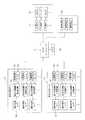
部品実装ライン10を構成する各部品実装機12の機外監視カメラ23で撮影した画像と、その画像認識結果(正常/異常)のデータは、該部品実装ライン10を管理するホストコンピュータ41にも送信される。ホストコンピュータ41は、受信した各部品実装機12の機外監視カメラ23の画像の中から、ホストコンピュータ41を操作する管理者等が選択した部品実装機12の機外監視カメラ23の画像を該ホストコンピュータ41のモニタ42(表示装置)に表示したり、上述した画像認識結果に基づいて監視対象の状態が正常時の状態と異なることが検出されたときにそれをホストコンピュータ41のモニタ42に警告表示したり、音声等で管理者等に警告するようにしている。尚、ホストコンピュータ41が管理する部品実装ライン10の本数は、1本のみであっても良いし、複数本であっても良い。 The image taken by the
ホストコンピュータ41で受信した各部品実装機12の機外監視カメラ23の画像と、その画像認識結果(正常/異常)のデータは、該ホストコンピュータ41とネットワークで接続された外部のコンピュータ(以下「外部PC」と表記する)43や携帯端末44にも送信され、それらを操作する者(管理者、作業者、技術者等)が選択した部品実装機12の機外監視カメラ23の画像を該外部PC43のモニタ45(表示装置)や携帯端末44の画面に表示したり、上述した画像認識結果に基づいて監視対象の状態が正常時の状態と異なることが検出されたときにそれを該外部PC43のモニタ45や携帯端末44の画面に警告表示したり、音声等で警告するようにしている。 The image of the
尚、部品実装機12の機外監視カメラ23の画像を、ホストコンピュータ41のモニタ42や、外部PC43のモニタ45や、携帯端末44の画面に表示する場合、それらを操作する者が選択した1台分の機外監視カメラ23の画像のみを表示するようにしても良いし、モニタ42,45や携帯端末44の画面を複数に分割して、1つの画面に複数台分の機外監視カメラ23の画像を分割表示するようにしても良い。或は、モニタ42,45や携帯端末44の画面に表示する1台分又は複数台分の機外監視カメラ23の画像を所定時間毎に自動的に他の機外監視カメラ23の画像に切り換えるようにしても良い。 When the image of the
また、ホストコンピュータ41、外部PC43及び携帯端末44は、各部品実装機12の記憶装置32に録画された機外監視カメラ23の画像を各部品実装機12のトレースログと同じ時刻情報付きでダウンロードして再生する機能も搭載されている。 Further, the
以上説明した本実施例では、部品実装機12の機外作業エリアを機外監視カメラ23で撮影してモニタ19,42,45や携帯端末44にリアルタイムで表示された画像又は部品実装機12の記憶装置32から読み出されて再生された画像を見て部品実装機12の機外作業エリアで作業者が作業した監視対象の状態を確認できるため、部品実装機12の稼働中にエラーの原因となる作業ミスの有無を監視して、エラー発生前に作業ミスを発見してエラーを未然に防いだり、作業ミスが原因でエラーが発生した場合でも、その原因となる作業ミスを機外作業エリアの画像から解明することができる。これにより、作業ミスが原因でエラーが発生した場合でも、そのエラーの原因が作業ミスであることを早期に解明してエラーを短時間で解決することができ、その分、部品実装機12の稼働率を向上させることができる。また、監視結果により作業ミスの内容や作業ミスの発生頻度も分かるため、作業者への「作業ミス防止」の注意喚起も行いやすくなり、作業ミスの減少にも繋がる。 In the present embodiment described above, the image or the
しかも、本実施例では、機外監視カメラ23で撮影した画像を、部品実装機12のエラー信号をトリガーにしてそのトリガーが発生した時刻よりも所定時間溯った時点から録画し、その録画する画像データには、部品実装機12のトレースログと同じ時刻情報と録画時間とエラー情報をリンクさせるようにしたので、部品実装機12のエラー発生時に部品実装機12の機外作業エリアの録画画像を、トレースログの解析結果やエラー情報と関連付けて確認することができ、部品実装機12で発生したエラーの原因をより詳細に解析できる。 Moreover, in this embodiment, the image taken by the
更に、本実施例では、機外監視カメラ23で撮影した画像を処理して監視対象の状態を認識する機能を搭載し、その画像認識結果に基づいて監視対象の状態が正常時の状態と異なることを検出したときにそれを警告表示するようにしたので、画像処理技術により作業ミスを自動的に検出できると共に、その作業ミスを警告表示して、作業ミスした作業をやり直すように作業者に促すことができる。 Further, in this embodiment, a function of processing an image taken by the
尚、図1の構成例では、各部品実装機12にそれぞれ機外監視カメラ23を設置するようにしたが、1台の機外監視カメラ23の視野内に複数台の部品実装機12の機外作業エリアを収めて1台の機外監視カメラ23で複数台の部品実装機12の機外作業エリアをまとめて撮影するようにしても良い。 In the configuration example of FIG. 1, the
また、部品実装機の前面側と背面側の2箇所に機外作業エリアが存在する場合は、部品実装機の前面側と背面側にそれぞれ機外監視カメラを設置して、前面側と背面側の2箇所の機外作業エリアを監視するようにすれば良い。 If there are two external work areas on the front side and the back side of the component mounting machine, install external monitoring cameras on the front side and the back side of the component mounting machine, respectively, on the front side and the back side. It suffices to monitor the two out-of-machine work areas.
その他、本発明は、機外監視カメラ23の設置場所を変更したり、部品実装機12の機外作業エリアに存在するフィーダ14以外の物まで監視するようにしても良い等、要旨を逸脱しない範囲内で種々変更して実施できることは言うまでもない。 In addition, the present invention does not deviate from the gist, such as changing the installation location of the
10…部品実装ライン、12…部品実装機、14…フィーダ、19…部品実装機のモニタ(表示装置)、22…リール、23…機外監視カメラ、31…部品実装機の制御装置(コンピュータ,画像認識装置)、32…記憶装置(録画装置)、41…ホストコンピュータ、42…ホストコンピュータのモニタ(表示装置)、43…外部PC(外部のコンピュータ)、44…携帯端末、45…外部PCのモニタ(表示装置) 10 ... Parts mounting line, 12 ... Parts mounting machine, 14 ... Feeder, 19 ... Parts mounting machine monitor (display device), 22 ... Reel, 23 ... External monitoring camera, 31 ... Parts mounting machine control device (computer, Image recognition device), 32 ... Storage device (recording device), 41 ... Host computer, 42 ... Host computer monitor (display device), 43 ... External PC (external computer), 44 ... Mobile terminal, 45 ... External PC Monitor (display device)
Claims (4)
Translated fromJapanese前記機外監視カメラで撮影した画像を表示する表示装置と、
前記機外監視カメラで撮影した画像を録画する録画装置とを備え、
前記表示装置にリアルタイムで表示された画像又は前記録画装置から読み出されて再生された画像を見て前記機外作業エリアで作業者が作業した監視対象の状態を確認できるようにした部品実装機の機外作業エリア監視システムであって、
前記機外監視カメラで撮影した画像を処理して前記監視対象の状態を認識する画像認識装置を備え、前記画像認識装置の認識結果に基づいて前記監視対象の状態が正常時の状態と異なることを検出したときにそれを前記表示装置に表示することを特徴とする部品実装機の機外作業エリア監視システム。An outside surveillance camera that captures the outside work area where a worker outside the parts mounting machine works on the parts mounting machine,
A display device that displays images taken by the external surveillance camera, and
It is equipped with a recording device that records images taken by the external surveillance camera.
Acomponent mounting machine that enables the operator to check the status of the monitored object worked in the outside work area by looking at the image displayed in real time on the display device or the image read and reproduced from the recording device.It is an outside work area monitoring system of
An image recognition device that processes an image taken by the external surveillance camera to recognize the state of the monitoring target is provided, and the state of the monitoring target is different from the normal state based on the recognition result of the image recognition device. An external work area monitoring system for a component mounting machine, characterizedin that when an image is detected, it is displayed on the display device .
前記監視対象は、少なくとも前記部品実装機への前記フィーダのセット中及びセット完了後の状態並びに前記フィーダへの部品供給テープのセット中及びセット完了後の状態であることを特徴とする請求項1に記載の部品実装機の機外作業エリア監視システム。The off-machine work area includes at least the area where the feeder is set.
Claim 1 is characterized in that the monitoring target is at least a state during and after the setting of the feeder on the component mounting machine, and a state during and after the setting of the component supply tape on the feeder. External work area monitoring system for component mounting machines described in.
Applications Claiming Priority (1)
| Application Number | Priority Date | Filing Date | Title |
|---|---|---|---|
| PCT/JP2016/078206WO2018055754A1 (en) | 2016-09-26 | 2016-09-26 | System for monitoring outside work area of component mounting machine |
Publications (2)
| Publication Number | Publication Date |
|---|---|
| JPWO2018055754A1 JPWO2018055754A1 (en) | 2019-07-04 |
| JP6823661B2true JP6823661B2 (en) | 2021-02-03 |
Family
ID=61690247
Family Applications (1)
| Application Number | Title | Priority Date | Filing Date |
|---|---|---|---|
| JP2018540583AActiveJP6823661B2 (en) | 2016-09-26 | 2016-09-26 | External work area monitoring system for component mounting machines |
Country Status (5)
| Country | Link |
|---|---|
| US (1) | US11464149B2 (en) |
| EP (1) | EP3518643B1 (en) |
| JP (1) | JP6823661B2 (en) |
| CN (1) | CN109792858B (en) |
| WO (1) | WO2018055754A1 (en) |
Families Citing this family (17)
| Publication number | Priority date | Publication date | Assignee | Title |
|---|---|---|---|---|
| WO2019089825A1 (en)* | 2017-11-02 | 2019-05-09 | AMP Robotics Corporation | Systems and methods for optical material characterization of waste materials using machine learning |
| WO2019202810A1 (en) | 2018-04-18 | 2019-10-24 | パナソニックIpマネジメント株式会社 | Component mounting system and tape scraps collecting device |
| JP7121138B2 (en)* | 2018-11-08 | 2022-08-17 | ヤマハ発動機株式会社 | Component mounter |
| US10481579B1 (en) | 2019-02-28 | 2019-11-19 | Nanotronics Imaging, Inc. | Dynamic training for assembly lines |
| US11209795B2 (en) | 2019-02-28 | 2021-12-28 | Nanotronics Imaging, Inc. | Assembly error correction for assembly lines |
| EP3912003A4 (en)* | 2019-02-28 | 2022-10-12 | Nanotronics Imaging, Inc. | ASSEMBLY ERROR CORRECTION FOR ASSEMBLY LINES |
| US11156991B2 (en) | 2019-06-24 | 2021-10-26 | Nanotronics Imaging, Inc. | Predictive process control for a manufacturing process |
| US11063965B1 (en) | 2019-12-19 | 2021-07-13 | Nanotronics Imaging, Inc. | Dynamic monitoring and securing of factory processes, equipment and automated systems |
| US11100221B2 (en) | 2019-10-08 | 2021-08-24 | Nanotronics Imaging, Inc. | Dynamic monitoring and securing of factory processes, equipment and automated systems |
| TWI760916B (en) | 2019-11-06 | 2022-04-11 | 美商奈米創尼克影像公司 | Manufacturing system for automatic production line in factory |
| US12165353B2 (en) | 2019-11-06 | 2024-12-10 | Nanotronics Imaging, Inc. | Systems, methods, and media for manufacturing processes |
| US12153408B2 (en) | 2019-11-06 | 2024-11-26 | Nanotronics Imaging, Inc. | Systems, methods, and media for manufacturing processes |
| WO2021102223A1 (en) | 2019-11-20 | 2021-05-27 | Nanotronics Imaging, Inc. | Securing industrial production from sophisticated attacks |
| US11086988B1 (en) | 2020-02-28 | 2021-08-10 | Nanotronics Imaging, Inc. | Method, systems and apparatus for intelligently emulating factory control systems and simulating response data |
| CN115004876B (en)* | 2020-03-11 | 2023-12-05 | 株式会社富士 | Management device, installation-related device, installation system, management method, and control method for installation-related device |
| CN113288190A (en)* | 2021-05-27 | 2021-08-24 | 上海联影医疗科技股份有限公司 | Monitoring system and medical system |
| JP7734337B2 (en)* | 2021-11-30 | 2025-09-05 | パナソニックIpマネジメント株式会社 | Management method, display method and management device |
Family Cites Families (17)
| Publication number | Priority date | Publication date | Assignee | Title |
|---|---|---|---|---|
| JPH01251458A (en)* | 1988-03-31 | 1989-10-06 | Sony Corp | Monitoring device |
| JPH0797856B2 (en)* | 1988-07-04 | 1995-10-18 | 花王株式会社 | Recording editing equipment |
| JPH0738279A (en)* | 1993-07-22 | 1995-02-07 | Matsushita Electric Ind Co Ltd | Electronic component mounting result management system |
| JPH09102700A (en)* | 1995-10-09 | 1997-04-15 | Matsushita Electric Ind Co Ltd | Quality analysis monitoring method |
| US6788987B2 (en) | 2001-03-07 | 2004-09-07 | Siemens Electronic Assembly Systems, Inc. | System and processes for performing quick changeovers on assembly lines |
| EP1343363A1 (en) | 2002-03-08 | 2003-09-10 | TraceXpert A/S | Feeder verification with a camera |
| TW200419640A (en)* | 2003-02-25 | 2004-10-01 | Matsushita Electric Industrial Co Ltd | Electronic component placement machine and electronic component placement method |
| US20060075631A1 (en)* | 2004-10-05 | 2006-04-13 | Case Steven K | Pick and place machine with improved component pick up inspection |
| US8594983B2 (en)* | 2006-03-20 | 2013-11-26 | Duetto Integrated Systems, Inc. | System for manufacturing laminated circuit boards |
| WO2008023757A1 (en)* | 2006-08-23 | 2008-02-28 | Yamaha Motor Co., Ltd. | Tape feeder and mounting apparatus |
| JP4901442B2 (en) | 2006-12-04 | 2012-03-21 | 東京エレクトロン株式会社 | Trouble cause investigation support device, trouble cause investigation support method, storage medium for storing program |
| JP4870054B2 (en) | 2007-09-20 | 2012-02-08 | ヤマハ発動機株式会社 | Substrate processing apparatus, surface mounting machine, printing machine, inspection machine, and coating machine |
| JP5438434B2 (en)* | 2008-08-29 | 2014-03-12 | Juki株式会社 | Electronic component mounting equipment |
| JP5454482B2 (en)* | 2011-01-20 | 2014-03-26 | パナソニック株式会社 | Component mounting apparatus and component mounting method |
| JP5854553B2 (en)* | 2011-10-18 | 2016-02-09 | 富士電機株式会社 | Visual inspection support device and control method of visual inspection support device |
| EP2922380B1 (en)* | 2012-11-13 | 2019-03-27 | FUJI Corporation | Substrate production state monitoring device |
| US10049282B2 (en)* | 2013-08-06 | 2018-08-14 | Mitsubishi Electric Corporation | Train interior monitoring method and train interior monitoring system |
- 2016
- 2016-09-26JPJP2018540583Apatent/JP6823661B2/enactiveActive
- 2016-09-26USUS16/328,457patent/US11464149B2/enactiveActive
- 2016-09-26CNCN201680089592.6Apatent/CN109792858B/enactiveActive
- 2016-09-26EPEP16916821.8Apatent/EP3518643B1/enactiveActive
- 2016-09-26WOPCT/JP2016/078206patent/WO2018055754A1/ennot_activeCeased
Also Published As
| Publication number | Publication date |
|---|---|
| CN109792858A (en) | 2019-05-21 |
| EP3518643A4 (en) | 2019-10-02 |
| EP3518643A1 (en) | 2019-07-31 |
| CN109792858B (en) | 2022-06-14 |
| US11464149B2 (en) | 2022-10-04 |
| WO2018055754A1 (en) | 2018-03-29 |
| US20210168976A1 (en) | 2021-06-03 |
| JPWO2018055754A1 (en) | 2019-07-04 |
| EP3518643B1 (en) | 2024-03-27 |
Similar Documents
| Publication | Publication Date | Title |
|---|---|---|
| JP6823661B2 (en) | External work area monitoring system for component mounting machines | |
| JP6661856B2 (en) | Devices and programs | |
| CN104770081B (en) | Substrate production status monitoring device | |
| JP5661527B2 (en) | Production management apparatus and production management method for component mounting line | |
| CN1326220C (en) | Element installation managing method, installation inspecting device and installation system | |
| JP2013243273A (en) | Component suction operation monitoring device and component presence detection device | |
| WO2016125262A1 (en) | Image processing device, mounting processing system, image processing method, and program | |
| JP2023093430A (en) | Equipment and programs | |
| WO2014030256A1 (en) | Electrical circuit fabrication line assistance system | |
| JP2008217608A (en) | Industrial machine remote monitoring system and method | |
| JP6956272B2 (en) | Trace support device | |
| CN113055595B (en) | Industrial camera control method, coil defect identification method and system | |
| JP2018107755A (en) | Information processing apparatus, control method of the same, and program | |
| JP7427050B2 (en) | Information processing system, information processing system control method, and program | |
| JP2017199740A (en) | Display system of component mounter | |
| JP2020022101A (en) | Monitoring device, production line, and control method of monitoring device | |
| CN104950867A (en) | Assembly mounter monitoring operation method | |
| KR102524763B1 (en) | The Apparatus For Notifying Error Of SMT Process Line | |
| WO2022003772A1 (en) | Component mounting system | |
| JP7182738B1 (en) | IN-FACTORY MONITORING DEVICE AND IN-FACTORY MONITORING METHOD | |
| JP7121138B2 (en) | Component mounter | |
| CN111386028B (en) | Substrate processing system | |
| JPH05167299A (en) | Device and method of checking chip mounting device cassette | |
| CN111417976A (en) | Work support system, work support method and program | |
| WO2016098176A1 (en) | Information processing device, information processing method, and program |
Legal Events
| Date | Code | Title | Description |
|---|---|---|---|
| A621 | Written request for application examination | Free format text:JAPANESE INTERMEDIATE CODE: A621 Effective date:20190722 | |
| A131 | Notification of reasons for refusal | Free format text:JAPANESE INTERMEDIATE CODE: A131 Effective date:20200727 | |
| A521 | Request for written amendment filed | Free format text:JAPANESE INTERMEDIATE CODE: A523 Effective date:20200903 | |
| TRDD | Decision of grant or rejection written | ||
| A01 | Written decision to grant a patent or to grant a registration (utility model) | Free format text:JAPANESE INTERMEDIATE CODE: A01 Effective date:20210104 | |
| A61 | First payment of annual fees (during grant procedure) | Free format text:JAPANESE INTERMEDIATE CODE: A61 Effective date:20210108 | |
| R150 | Certificate of patent or registration of utility model | Ref document number:6823661 Country of ref document:JP Free format text:JAPANESE INTERMEDIATE CODE: R150 | |
| R250 | Receipt of annual fees | Free format text:JAPANESE INTERMEDIATE CODE: R250 | |
| R250 | Receipt of annual fees | Free format text:JAPANESE INTERMEDIATE CODE: R250 |