JP6821983B2 - Liquid injection device - Google Patents
Liquid injection deviceDownload PDFInfo
- Publication number
- JP6821983B2 JP6821983B2JP2016139149AJP2016139149AJP6821983B2JP 6821983 B2JP6821983 B2JP 6821983B2JP 2016139149 AJP2016139149 AJP 2016139149AJP 2016139149 AJP2016139149 AJP 2016139149AJP 6821983 B2JP6821983 B2JP 6821983B2
- Authority
- JP
- Japan
- Prior art keywords
- liquid
- liquid chamber
- posture
- chamber
- liquid injection
- Prior art date
- Legal status (The legal status is an assumption and is not a legal conclusion. Google has not performed a legal analysis and makes no representation as to the accuracy of the status listed.)
- Active
Links
- 239000007788liquidSubstances0.000titleclaimsdescription632
- 238000002347injectionMethods0.000titleclaimsdescription159
- 239000007924injectionSubstances0.000titleclaimsdescription159
- 230000007246mechanismEffects0.000claimsdescription77
- 238000006073displacement reactionMethods0.000claimsdescription50
- 238000012423maintenanceMethods0.000claimsdescription45
- 238000003860storageMethods0.000claimsdescription41
- 230000002093peripheral effectEffects0.000claimsdescription21
- 230000036544postureEffects0.000description94
- 238000004140cleaningMethods0.000description33
- 238000004891communicationMethods0.000description8
- 238000003825pressingMethods0.000description8
- 230000004048modificationEffects0.000description7
- 238000012986modificationMethods0.000description7
- 238000000034methodMethods0.000description6
- 230000008569processEffects0.000description6
- 238000006243chemical reactionMethods0.000description5
- 230000007547defectEffects0.000description5
- 229920001971elastomerPolymers0.000description5
- 238000011010flushing procedureMethods0.000description5
- 239000000463materialSubstances0.000description5
- 239000002699waste materialSubstances0.000description5
- 238000007599dischargingMethods0.000description4
- 230000000694effectsEffects0.000description4
- 239000000976inkSubstances0.000description4
- 230000007423decreaseEffects0.000description3
- 239000000806elastomerSubstances0.000description3
- 239000000049pigmentSubstances0.000description3
- 230000009257reactivityEffects0.000description3
- 229920005549butyl rubberPolymers0.000description2
- 230000008859changeEffects0.000description2
- 239000004744fabricSubstances0.000description2
- 238000001914filtrationMethods0.000description2
- 239000011344liquid materialSubstances0.000description2
- 230000005499meniscusEffects0.000description2
- 238000007789sealingMethods0.000description2
- 238000004062sedimentationMethods0.000description2
- 239000000126substanceSubstances0.000description2
- 230000037303wrinklesEffects0.000description2
- 238000013459approachMethods0.000description1
- 230000008901benefitEffects0.000description1
- 239000003086colorantSubstances0.000description1
- 238000004040coloringMethods0.000description1
- 239000000470constituentSubstances0.000description1
- 238000011109contaminationMethods0.000description1
- 239000006185dispersionSubstances0.000description1
- 238000004090dissolutionMethods0.000description1
- 238000001035dryingMethods0.000description1
- 239000007772electrode materialSubstances0.000description1
- 238000005401electroluminescenceMethods0.000description1
- 230000005484gravityEffects0.000description1
- 238000009434installationMethods0.000description1
- 230000001788irregularEffects0.000description1
- 239000004973liquid crystal related substanceSubstances0.000description1
- 238000004519manufacturing processMethods0.000description1
- 239000003595mistSubstances0.000description1
- 239000004745nonwoven fabricSubstances0.000description1
- 239000002245particleSubstances0.000description1
- 239000002985plastic filmSubstances0.000description1
- 229920006255plastic filmPolymers0.000description1
- 239000011148porous materialSubstances0.000description1
- 239000011347resinSubstances0.000description1
- 229920005989resinPolymers0.000description1
- 230000035939shockEffects0.000description1
- 238000003756stirringMethods0.000description1
- 238000011144upstream manufacturingMethods0.000description1
Images


Landscapes
- Ink Jet (AREA)
Description
Translated fromJapanese本発明は、プリンターなどの液体噴射装置に関する。 The present invention relates to a liquid injection device such as a printer.
液体噴射装置の一例として、液体噴射ヘッドに供給される液体を一時貯留するサブタンクに溜まった気体を排出するために、サブタンクを傾けた状態で液体噴射ヘッドの吸引を行うインクジェット式のプリンターがある(例えば、特許文献1)。 As an example of the liquid injection device, there is an inkjet printer that sucks the liquid injection head with the sub tank tilted in order to discharge the gas accumulated in the sub tank that temporarily stores the liquid supplied to the liquid injection head ( For example, Patent Document 1).
流路の途中にあるサブタンクに液体を貯留すると、気泡として混入した気体がサブタンクの上部に溜まっていく。こうした気体は、吸引等のメンテナンスを行うときには、液体よりも先にサブタンクから流出させることが好ましい。しかし、サブタンクにおいて気体が流出しやすい構造を採用すると、液体を噴射するときにも気体が流出して、噴射不良を生じてしまう、という課題がある。 When the liquid is stored in the sub tank in the middle of the flow path, the gas mixed as bubbles accumulates in the upper part of the sub tank. When performing maintenance such as suction, it is preferable that such a gas flows out of the sub tank before the liquid. However, if a structure in which the gas easily flows out is adopted in the sub tank, there is a problem that the gas flows out even when the liquid is injected, resulting in injection failure.
このような課題は、インクを噴射して印刷を行うプリンターに限らず、液体噴射ヘッドに供給する液体を流路の途中で貯留する液室を有する液体噴射装置においては、概ね共通したものとなっている。 Such problems are generally common not only in printers that eject ink to print, but also in liquid injection devices that have a liquid chamber that stores the liquid supplied to the liquid injection head in the middle of the flow path. ing.
本発明は、こうした実情に鑑みてなされたものであり、その目的は、メンテナンスを行うときに液体を噴射するときよりも気体が排出されやすくなる液体噴射装置を提供することにある。 The present invention has been made in view of such circumstances, and an object of the present invention is to provide a liquid injection device in which a gas is more easily discharged than when a liquid is injected during maintenance.
以下、上記課題を解決するための手段及びその作用効果について記載する。
上記課題を解決する液体噴射装置は、ノズルを有して、媒体に向けて前記ノズルから液体を噴射する液体噴射ヘッドと、前記液体が流入する流入口及び前記液体噴射ヘッドに向けて前記液体が流出する流出口を有して、前記液体噴射ヘッドに供給される前記液体を貯留する液室と、前記液体噴射ヘッド及び前記液室を、前記媒体に向けて前記液体を噴射するときの第1姿勢と、前記液体噴射ヘッドのメンテナンスを行うときの第2姿勢とに変位させる変位機構と、を備え、前記第1姿勢での前記液室内における前記流出口の位置は、前記第2姿勢での前記液室内における前記流出口の位置よりも低い。Hereinafter, means for solving the above problems and their actions and effects will be described.
The liquid injection device that solves the above problems has a nozzle, and the liquid injection head that injects the liquid from the nozzle toward the medium, the inflow port into which the liquid flows, and the liquid toward the liquid injection head. A first when a liquid chamber having an outflow outlet for storing the liquid supplied to the liquid injection head and the liquid injection head and the liquid chamber are used to inject the liquid toward the medium. It is provided with a posture and a displacement mechanism that displaces the liquid injection head to a second posture when performing maintenance, and the position of the outlet in the liquid chamber in the first posture is the position of the outlet in the second posture. It is lower than the position of the outlet in the liquid chamber.
この構成によれば、媒体に向けて液体を噴射するときには、液室が第1姿勢になって流出口が低い位置に配置されるので、液室内に溜まった気体が流出しにくい。そのため、媒体に向けて液体を噴射するときに、ノズルに気泡が混入することに起因する噴射不良が生じにくい。一方、メンテナンスを行うときには、液室が第2姿勢になって流出口が高い位置に配置されるので、液室内に溜まった気体が流出しやすくなる。そのため、メンテナンスを行うときには液体を噴射するときよりも気体が排出されやすくなる。 According to this configuration, when the liquid is injected toward the medium, the liquid chamber is in the first posture and the outlet is arranged at a low position, so that the gas accumulated in the liquid chamber is unlikely to flow out. Therefore, when the liquid is injected toward the medium, injection defects due to the inclusion of air bubbles in the nozzle are unlikely to occur. On the other hand, when performing maintenance, the liquid chamber is in the second posture and the outlet is arranged at a high position, so that the gas accumulated in the liquid chamber tends to flow out. Therefore, when performing maintenance, the gas is more likely to be discharged than when the liquid is injected.
上記液体噴射装置において、前記流出口は、前記第1姿勢では前記流入口より低い位置にあり、前記第2姿勢では前記流入口より高い位置にある。
この構成によれば、媒体に向けて液体を噴射する第1姿勢では、液室の流出口が流入口より低い位置にあるので、液室内に溜まった気体が流出しにくく、液体を噴射する時に流入口から液室内に流入してきた気体も流出しにくい。一方、メンテナンスを行うときには、液室の流出口が流入口より高い位置にあるので、液室内に溜まった気体が流出しやすく、メンテナンスにより流入口から液室内に流入してきた気体も流出しやすい。そのため、メンテナンスを行うときには液体を噴射するときよりも気体が排出されやすくなる。In the liquid injection device, the outlet is located lower than the inlet in the first posture and higher than the inlet in the second posture.
According to this configuration, in the first posture of injecting the liquid toward the medium, the outflow port of the liquid chamber is located at a position lower than the inflow port, so that the gas accumulated in the liquid chamber does not easily flow out, and when the liquid is injected, it is difficult to flow out. The gas that has flowed into the liquid chamber from the inflow port is also unlikely to flow out. On the other hand, when performing maintenance, since the outlet of the liquid chamber is located higher than the inlet, the gas accumulated in the liquid chamber tends to flow out, and the gas that has flowed into the liquid chamber from the inlet due to maintenance also tends to flow out. Therefore, when performing maintenance, the gas is more likely to be discharged than when the liquid is injected.
上記液体噴射装置は、前記液体を貯留する液体貯留部と前記流入口とを接続する供給流路と、前記液室と前記液体貯留部とを接続する返送流路と、前記返送流路において前記液体を前記液室から前記液体貯留部に向けて流動させるポンプと、を備え、前記液室は、前記返送流路に前記液体を流出させる返送口を有し、前記第1姿勢での前記液室における前記返送口の位置は、前記第2姿勢での前記液室における前記返送口の位置よりも高い。 The liquid injection device has a supply flow path connecting the liquid storage section for storing the liquid and the inflow port, a return flow path connecting the liquid chamber and the liquid storage section, and the return flow path. The liquid chamber includes a pump for flowing a liquid from the liquid chamber toward the liquid storage portion, and the liquid chamber has a return port for discharging the liquid to the return flow path, and the liquid in the first posture. The position of the return port in the chamber is higher than the position of the return port in the liquid chamber in the second posture.
この構成によれば、媒体に向けて液体を噴射するときには、液室が第1姿勢になって返送口が高い位置に配置されるので、ポンプの駆動に伴って、液室に溜まった気体を返送流路を通じて液体貯留部に移動させることができる。そのため、媒体に向けて液体を噴射するときに、ノズルに気泡が混入することに起因する噴射不良が生じにくい。また、ポンプを駆動すると、液室、返送流路、液体貯留部及び供給流路の順に液体を循環させることができる。液室を第2姿勢にして液体を循環させた場合、返送口が低い位置に配置されるので、液室内に沈降した成分を含む液体を効率よく攪拌することができる。 According to this configuration, when the liquid is injected toward the medium, the liquid chamber is in the first posture and the return port is arranged at a high position, so that the gas accumulated in the liquid chamber is removed as the pump is driven. It can be moved to the liquid reservoir through the return channel. Therefore, when the liquid is injected toward the medium, injection defects due to the inclusion of air bubbles in the nozzle are unlikely to occur. Further, when the pump is driven, the liquid can be circulated in the order of the liquid chamber, the return flow path, the liquid storage section, and the supply flow path. When the liquid is circulated with the liquid chamber in the second posture, the return port is arranged at a low position, so that the liquid containing the components settled in the liquid chamber can be efficiently agitated.
上記液体噴射装置は、前記液体を貯留する液体貯留部と前記流入口とを接続する供給流路と、前記液室と前記液体貯留部とを接続する返送流路と、前記返送流路において前記液体を前記液室から前記液体貯留部に向けて流動させるポンプと、を備え、前記液室は、前記返送流路に前記液体を流出させる返送口を有し、前記返送口は、前記第1姿勢では前記流出口より高い位置にあり、前記第2姿勢では前記流出口より低い位置にある。 The liquid injection device has a supply flow path connecting the liquid storage section for storing the liquid and the inflow port, a return flow path connecting the liquid chamber and the liquid storage section, and the return flow path. The liquid chamber includes a pump for flowing a liquid from the liquid chamber toward the liquid storage portion, the liquid chamber has a return port for discharging the liquid into the return flow path, and the return port is the first. In the posture, it is higher than the outlet, and in the second posture, it is lower than the outlet.
この構成によれば、液室が第1姿勢になると、返送口が流出口より高い位置に配置されるので、媒体に向けて液体を噴射するときに液体噴射ヘッドの方に気泡が流れにくい。また、ポンプを駆動すると、液室、返送流路、液体貯留部及び供給流路の順に液体を循環させることができる。液室を第2姿勢にして液体を循環させた場合、返送口が低い位置に配置されるので、液室内に沈降した成分を含む液体を効率よく攪拌することができる。 According to this configuration, when the liquid chamber is in the first posture, the return port is arranged at a position higher than the outlet, so that it is difficult for air bubbles to flow toward the liquid injection head when the liquid is injected toward the medium. Further, when the pump is driven, the liquid can be circulated in the order of the liquid chamber, the return flow path, the liquid storage section, and the supply flow path. When the liquid is circulated with the liquid chamber in the second posture, the return port is arranged at a low position, so that the liquid containing the components settled in the liquid chamber can be efficiently agitated.
上記液体噴射装置では、前記メンテナンスとして、前記ポンプの駆動により、前記ノズルから前記液体を流出させる。
この構成によれば、メンテナンスとして、ポンプの駆動力によってノズルを通じて液体噴射ヘッド及び液室から液体とともに気泡等の異物を排出させる加圧クリーニングを実行することができる。In the liquid injection device, as the maintenance, the liquid is discharged from the nozzle by driving the pump.
According to this configuration, as maintenance, pressure cleaning can be performed in which foreign matter such as air bubbles is discharged together with the liquid from the liquid injection head and the liquid chamber through the nozzle by the driving force of the pump.
上記液体噴射装置において、前記液体噴射ヘッドは、前記ノズルが開口する開口面を有し、前記第1姿勢は前記開口面が水平に対して傾く姿勢であり、前記第2姿勢は前記開口面の水平に対する傾きが前記第1姿勢よりも小さくなる姿勢である。 In the liquid injection device, the liquid injection head has an opening surface through which the nozzle opens, the first posture is a posture in which the opening surface is inclined with respect to the horizontal, and the second posture is a posture in which the opening surface is inclined. This is a posture in which the inclination with respect to the horizontal is smaller than that of the first posture.
この構成によれば、変位機構は、開口面の水平に対する傾きが変化するように液体噴射ヘッドを変位させるので、液体噴射ヘッドと一緒に液室を最大90度まで傾けて、液室内における流出口等の高さを変化させることができる。 According to this configuration, the displacement mechanism displaces the liquid injection head so that the inclination of the opening surface with respect to the horizontal changes. Therefore, the liquid chamber is tilted up to 90 degrees together with the liquid injection head, and the outlet in the liquid chamber is tilted. Etc. can be changed in height.
上記液体噴射装置は、前記メンテナンスとして、前記ノズルから前記液体を吸引するメンテナンス装置を備える。
この構成によれば、メンテナンスとして、ノズルを通じて液体噴射ヘッド及び液室内の液体を吸引することにより、液体とともに気泡等の異物を排出させる吸引クリーニングを実行することができる。The liquid injection device includes a maintenance device for sucking the liquid from the nozzle as the maintenance.
According to this configuration, as maintenance, suction cleaning can be performed by sucking the liquid in the liquid injection head and the liquid chamber through the nozzle to discharge foreign substances such as air bubbles together with the liquid.
上記液体噴射装置は、前記流入口を開閉可能な弁体と、前記流入口を閉塞する方向に前記弁体を付勢する付勢部材と、を備え、前記液室は、前記液室の内圧と外圧との差圧に応じて変位可能な可撓部を壁面の一部として有し、前記弁体は、前記可撓部の変位に伴って前記流入口を開閉する。 The liquid injection device includes a valve body capable of opening and closing the inflow port and an urging member for urging the valve body in a direction of closing the inflow port, and the liquid chamber is the internal pressure of the liquid chamber. A flexible portion that can be displaced according to the differential pressure between the and external pressure is provided as a part of the wall surface, and the valve body opens and closes the inflow port according to the displacement of the flexible portion.
この構成によれば、液室の内圧と外圧との差圧に応じて可撓部が変位することによって弁体が流入口を開閉するので、液体噴射ヘッドに液体を供給する液室の圧力を適切に調整することができる。 According to this configuration, the valve body opens and closes the inflow port by displacement of the flexible portion according to the differential pressure between the internal pressure and the external pressure of the liquid chamber, so that the pressure of the liquid chamber that supplies the liquid to the liquid injection head is increased. Can be adjusted appropriately.
上記液体噴射装置において、前記液室は、前記可撓部とは別の壁面である内周面を有し、前記液室の内側に配置され、前記可撓部の変位に伴って、前記内周面に沿って移動する受圧部材を備える。 In the liquid injection device, the liquid chamber has an inner peripheral surface which is a wall surface different from the flexible portion, is arranged inside the liquid chamber, and is located inside the flexible portion as the flexible portion is displaced. A pressure receiving member that moves along the peripheral surface is provided.
この構成によれば、受圧部材が液室内で内周面に沿って移動することにより、圧力変動に伴う可撓部の変位を安定させることができる。
上記液体噴射装置は、前記液室の外側に配置され、前記可撓部の変位に伴って移動する変位部材と、前記可撓部を有する可撓部材と、前記可撓部材の外縁を押さえて固定する固定部材と、を備え、前記固定部材は、前記変位部材の移動を案内する案内部を有し、前記変位部材は、前記可撓部よりも前記案内部に対する摩擦係数が小さい。According to this configuration, the pressure receiving member moves along the inner peripheral surface in the liquid chamber, so that the displacement of the flexible portion due to the pressure fluctuation can be stabilized.
The liquid injection device is arranged outside the liquid chamber and presses a displacement member that moves with the displacement of the flexible portion, a flexible member having the flexible portion, and an outer edge of the flexible member. A fixing member for fixing is provided, and the fixing member has a guide portion for guiding the movement of the displacement member, and the displacement member has a friction coefficient with respect to the guide portion smaller than that of the flexible portion.
この構成によれば、可撓部が変位するときに、可撓部よりも摩擦係数が小さい変位部材が案内部に接触するので、圧力変動に伴う可撓部の変位を安定させることができる。 According to this configuration, when the flexible portion is displaced, a displacement member having a friction coefficient smaller than that of the flexible portion comes into contact with the guide portion, so that the displacement of the flexible portion due to pressure fluctuation can be stabilized.
以下、液体噴射装置の実施形態について、図を参照して説明する。液体噴射装置は、例えば、用紙などの媒体に液体の一例であるインクを噴射することによって記録(印刷)を行うインクジェット式のプリンターである。 Hereinafter, embodiments of the liquid injection device will be described with reference to the drawings. The liquid injection device is, for example, an inkjet printer that records (prints) by injecting ink, which is an example of a liquid, onto a medium such as paper.
(第1実施形態)
第1実施形態では、鉛直下方を重力方向Zとし、水平な方向であって互いに異なる2方向を第1方向X、第2方向Yとする。(First Embodiment)
In the first embodiment, the vertically downward direction is the gravity direction Z, and the two horizontal directions that are different from each other are the first direction X and the second direction Y.
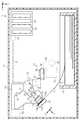
図1に示すように、本実施形態の液体噴射装置11は、筐体12と、筐体12内で液体を噴射する液体噴射ヘッド13と、液体噴射ヘッド13のメンテナンスを行うメンテナンス装置31と、液体噴射ヘッド13を変位させる変位機構14と、複数の媒体Sを収容するカセット17と、カセット17から給送された媒体Sを支持する支持部18と、備える。また、液体噴射装置11は、メンテナンス装置31を第2方向Yに沿って移動させる移動機構34と、液体噴射ヘッド13、変位機構14、メンテナンス装置31及び移動機構34の動作を制御する制御部100と、を備える。 As shown in FIG. 1, the
筐体12の内側または外側(本実施形態では筐体12の内側)には、液体噴射ヘッド13に供給する液体を収容する1または複数(本実施形態では4つ)の液体収容体19が装着される装着部20が設けられる。液体収容体19は、着脱可能なカートリッジであってもよいし、液体を注入可能なタンクであってもよい。 One or more (four in this embodiment) of liquid
また、液体噴射装置11は、液体噴射ヘッド13に液体を供給する液体供給路21と、液体供給路21に設けられる圧力調整機構24と、液体を加圧するための加圧機構22とを備える。液体供給路21には、圧力調整機構24に流入する液体を濾過するフィルター25と、圧力調整機構24から流出する液体を濾過するフィルター27と、を配置することが好ましい。 Further, the
加圧機構22の動作により、加圧された液体が液体供給路21を通じて液体噴射ヘッド13に供給される。加圧機構22は、液体収容体19内の液体を加圧してもよいし、液体収容体19から吸引した液体を下流に向けて加圧供給するようにしてもよい。 By the operation of the
変位機構14は、液体噴射ヘッド13を保持する保持部材15を備え、回動軸16を中心に保持部材15を矢印で示すように回動させることによって、液体噴射ヘッド13を図1に実線で示す第1姿勢と、図1に二点鎖線で示す第2姿勢とに変位させる。液体噴射ヘッド13は、媒体Sに向けて液体を噴射する複数のノズル23と、ノズル23が開口する開口面13bとを有する。液体噴射ヘッド13が複数の異なる種類の液体(例えば、異なる色のインク)を噴射する場合、少なくとも、ノズル23、液体供給路21及び圧力調整機構24は液体の種類毎に設けられる。 The
第1姿勢は、例えば、液体噴射ヘッド13の開口面13bが水平に対して傾く姿勢であり、第2姿勢は、開口面13bの水平に対する傾きが第1姿勢よりも小さくなる姿勢である。本実施形態において、液体噴射ヘッド13が第2姿勢のときに開口面13bは水平になるが、必ずしも水平でなくてもよく、第1姿勢のときよりも開口面13bが水平に近くなればよい。すなわち、「開口面13bの水平に対する傾きが第1姿勢よりも小さくなる」とは、開口面13bの水平に対する傾きがゼロになって、開口面13bが水平になることを含む。 The first posture is, for example, a posture in which the
液体噴射ヘッド13は、第1姿勢になったときに、支持部18に支持された媒体Sに液体を液滴として噴射することで、印刷処理を行う。本実施形態において、支持部18上において媒体Sが進む方向を搬送方向Fとし、第1姿勢になった液体噴射ヘッド13が液体を噴射する方向を噴射方向Jとする。また、搬送方向F及び噴射方向Jの双方と異なる方向を幅方向Wとする。本実施形態の液体噴射ヘッド13は、幅方向Wの印刷範囲が媒体Sの幅以上になるように配置された多数のノズル23を有するラインヘッドを構成する。 When the
次に、メンテナンス装置31の構成について例示する。
メンテナンス装置31は、液体噴射ヘッド13に対する相対移動に伴って開口面13bを払拭する払拭部材32と、ノズル23から排出される液体を受容するキャップ33と、キャップ33内を吸引する吸引機構36と、を備える。吸引機構36は、吸引流路35によりキャップ33と廃液収容部37に接続されている。払拭部材32は、例えばゴム部材やエラストマーなど、弾性変形可能な板状部材から構成することが好ましいが、不織布等、液体を吸収可能な布や多孔質材などで構成してもよい。Next, the configuration of the
The
メンテナンス装置31は、液体噴射ヘッド13が第2姿勢のときに、キャッピング、クリーニング及びワイピング(払拭)を含むメンテナンス動作を行う。
キャッピングは、図1に二点鎖線で示すように、キャップ33が液体噴射ヘッド13の下方にあるときに実行される。キャッピングを実行する際には、キャップ33が上昇移動して、開口面13bとの間に閉空間を形成する。キャッピングを行うときのメンテナンス装置31の位置をキャッピング位置という。キャッピングは、電源オフ時を含め、液体噴射ヘッド13が液体の噴射動作を休止するときに、ノズル23の乾燥を抑制するために行う。The
Capping is performed when the
クリーニングの一種である吸引クリーニングの実行にあたっては、まず、キャップ33が上昇移動してキャッピングを行う。そして、キャップ33が開口面13bとの間に閉空間を形成した状態で吸引機構36が駆動すると、液体噴射ヘッド13内などにある気泡等の異物が液体とともにノズル23から排出される。 In executing suction cleaning, which is a type of cleaning, first, the
他のクリーニングとして、加圧機構22の加圧により液体噴射ヘッド13からキャップ33内に液体を排出させる加圧クリーニングを行うようにしてもよい。クリーニングは、キャップ33が液体噴射ヘッド13の下方にあるときに行われる。クリーニングを行うときのメンテナンス装置31の位置(図1に二点鎖線で示す位置)を受容位置という。クリーニングは、印刷処理の開始前または印刷処理の実行後などに行なわれる。 As another cleaning, pressure cleaning may be performed in which the liquid is discharged from the
ワイピングは、液体噴射ヘッド13が払拭部材32に対して相対移動することで、実行される。本実施形態では、払拭部材32を含むメンテナンス装置31が支持部18から遠ざかる第2方向Yに移動することにより、払拭部材32の先端部分で開口面13bを払拭する。 Wiping is performed by the
ワイピングを行う時に、加圧機構22の加圧により液体噴射ヘッド13のノズル23から液体が排出されない程度に液面を膨出させてもよい。このように、ノズル23内を加圧した状態で行うワイピングを加圧ワイピングという。加圧ワイピングでは、払拭に伴ってノズル23内に異物が押し込まれにくい、という利点がある。 When wiping, the liquid level may be swelled to the extent that the liquid is not discharged from the
ワイピングは、液体噴射ヘッド13に液体などの汚れが付着したときに行うことが好ましい。例えば、クリーニングの後には、開口面13bにノズル23から排出された液体が付着しているので、ワイピングを行うとよい。また、液体噴射ヘッド13が媒体Sに向けて液体を噴射していると、その噴射に伴って微細なミストが発生し、開口面13b等に付着していく。その付着量が多くなると、付着した液体が液滴となって垂れ落ち、媒体Sや周辺の部材を汚してしまうことがある。そのため、印刷処理が長時間に及ぶ場合などには、液体が垂れ落ちないように、所定のタイミングで印刷処理の途中にワイピングを行ってもよい。 Wiping is preferably performed when dirt such as liquid adheres to the
また、液体噴射ヘッド13は、メンテナンス動作として、軽微な噴射不良が生じたときやワイピングの後などに、液体を噴射して吐き捨てるフラッシングを行う。液体噴射ヘッド13が第2姿勢のときには、移動機構34がメンテナンス装置31を受容位置に移動させてフラッシングを行い、フラッシングにより吐き捨てられた液体をキャップ33で受容するとよい。この場合、キャップ33は上昇移動させず、液体噴射ヘッド13から離れた位置に配置しておく方がよい。また、キャップ33で受容した液体は、吸引機構36の駆動により、廃液収容部37に収容するとよい。 Further, as a maintenance operation, the
支持部18に、媒体Sを支持するリブ18aと、リブ18aの周囲に設けられた凹状の液体受容部18bとを設け、支持部18上に媒体Sがないときに液体受容部18bに向けてフラッシングを行うようにしてもよい。この場合、液体噴射ヘッド13は、第1姿勢でフラッシングを行うことになる。 The
支持部18に液体受容部18bを設けておくと、例えば複数の媒体Sに連続して印刷処理を行う場合に、搬送される媒体Sと媒体Sとの間(紙間)に、液体噴射ヘッド13が第1姿勢のままでフラッシングを行うことができる。そのため、液体噴射ヘッド13が印刷処理の途中に第2姿勢に変位してキャップ33に向けてフラッシングを行うより、メンテナンス動作の時間を短縮できる。なお、液体受容部18bで受容した液体を、図示しない廃液チューブ等を通じて廃液収容部37に収容してもよい。 When the
次に、圧力調整機構24の構成について例示する。
なお、図2には圧力調整機構24の内部構造を示し、図3及び図4には圧力調整機構24の構成部材を示す。Next, the configuration of the
Note that FIG. 2 shows the internal structure of the
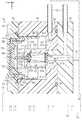
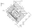
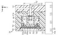
図2に示すように、液体供給路21において、圧力調整機構24に液体を流入させる部分を流入路21aといい、圧力調整機構24から液体を流出させる部分を流出路21bという。圧力調整機構24は、液体噴射ヘッド13に供給される液体を一時貯留する液室41を備える。圧力調整機構24は、流入路21aが形成された第1流路形成部材51と、液室41及び流出路21bが形成された第2流路形成部材52と、を重ねて構成される(図3及び図4を併せて参照)。 As shown in FIG. 2, in the
液室41は、第1流路形成部材51の一面側(図2では左面側)に凹設された凹部を構成する円形の内底部41aと円筒状の内周面41bとを壁面として有する。液室41において、内底部41a側を底側、凹部が開口する側を天側とする。 The
第1流路形成部材51は、内底部41a及び内周面41bの中心軸Caと中心軸が重なるとともにその中心軸に沿って流入路21aが貫通する円筒状の突出流路51aを有する。第2流路形成部材52は、第1流路形成部材51と重なったときに突出流路51aを収容する円筒状の収容凹部52aと、収容凹部52aの内底部から液室41内に突出する円筒状の円筒突部52bと、を有する。円筒突部52bの外周面には、中心軸Caに沿って延びる複数の溝52c(図4を併せて参照)を設けることが好ましい。 The first flow
突出流路51aが収容凹部52aに収容される態様で第1流路形成部材51と第2流路形成部材52が重なると、突出流路51aの先端面と円筒突部52bの内部空間とにより、供給室42が囲み形成される。そして、円筒突部52bの液室41内に突出した先端部分には、液室41と供給室42を連通させる連通孔43が形成される。 When the first flow
連通孔43の液室41と連通する開口は、流入路21aから供給室42に流入した液体が液室41に流入する流入口43aである。また、液室41の内底部41aには、流出路21bに向けて液体が流出する流出口44が形成される。液室41が図2に示す第2姿勢のとき、中心軸Caは実質的に水平になる。このとき、流出口44は中心軸Caよりも鉛直上方に配置され、流入口43aは中心軸Ca上に配置される。 The opening that communicates with the
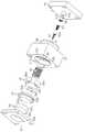
圧力調整機構24は、液室41の天側の壁面を構成する可撓部材53と、可撓部材53の外縁を液室41の外側から押さえて第2流路形成部材52に固定する固定部材54と、液室41の外側に配置されて可撓部材53に重なる変位部材55と、液室41の内側に配置される受圧部材56と、を備える。 The
可撓部材53は、エラストマー(例えば、ブチルゴムなどのゴム)等の弾性体で構成することができる。第1流路形成部材51、第2流路形成部材52及び固定部材54は、第2流路形成部材52と固定部材54の間に可撓部材53の外縁を挟んだ状態で、例えばねじなどの固定具57により、相互に固定される(図3を併せて参照)。このとき、第1流路形成部材51と第2流路形成部材52の間には、Oリング58などの弾性体を挟むと、液体の漏出を抑制することができる。 The
可撓部材53は、内底部41aと内周面41bからなる凹部の開口を塞ぐ態様で配置される。このとき、可撓部材53の外面側は大気に開放されている。可撓部材53の外縁から中心に向けて延びる部分は、内周面41bに沿って液室41内に入り込んだ後、折り返されて液室41の外側に向かうように湾曲する湾曲部53aを形成する。可撓部材53の中心部分は液室41の開口と同心円状をなす受圧壁53cを形成する。可撓部材53において湾曲部53aと受圧壁53cの間は、内周面41bの内側に位置する円筒部53bを形成する。受圧壁53cは、湾曲部53a及び円筒部53bよりも肉厚にすることが好ましい。円筒部53b、受圧壁53c及び湾曲部53aは、液室41の壁面の一部を構成する可撓部として機能する。 The
変位部材55は、可撓部材53の円筒部53bの外周側に重なる円筒状の側壁55bと、側壁55bの一端側(天側の端)を塞ぐ円盤部55cとを有する。固定部材54には、変位部材55の円盤部55cが挿通可能な円筒状の貫通孔54aが形成される。固定部材54は、可撓部材53の湾曲部53aの外縁を押さえる態様で、貫通孔54aを液室41の底側に向けて延設する突入部54bを形成するとよい。 The
受圧部材56は、可撓部材53の円筒部53bの内周側に重なる円筒状の小径円筒部56bと、小径円筒部56bの先端に位置して受圧壁53cと重なる受圧部56cと、小径円筒部56bより大径の大径円筒部56aと、を有する。受圧部材56には、大径円筒部56a等に、液体を流通させるための流通孔56d(図3及び図4を併せて参照)を形成するとよい。 The
受圧部材56は、小径円筒部56b及び受圧部56cがそれぞれ可撓部材53の円筒部53b及び受圧壁53cと重なったときに、小径円筒部56bと大径円筒部56aの間に形成される段差部分に湾曲部53aが重なる。なお、受圧部56cと受圧壁53cが接する部分には、凹凸形状を形成して、両者が凹凸形状で係合するようにすることが好ましい。 The
可撓部材53は、液室41の内圧が高くなると、液室41の内容積を大きくする方向(図2では左方向)に円筒部53b及び受圧壁53cが移動し、その移動に伴って湾曲部53aが撓み変位する。また、可撓部材53は、液室41の内圧が低くなると、液室41の内容積を小さくする方向(図2では右方向)に円筒部53b及び受圧壁53cが移動し、その移動に伴って湾曲部53aが撓み変位する。 When the internal pressure of the
変位部材55及び受圧部材56は、可撓部材53の変位に追従して、円筒部53b及び受圧壁53cと同じ方向に変位する。液室41の圧力変動に伴って可撓部材53が撓み変位するとき、受圧部材56は、大径円筒部56aが液室41の内周面41bに沿って移動する。すなわち、受圧部材56は、可撓部材53の可撓部の変位に伴って、液室41の内周面41b(可撓部とは別の液室41の壁面)に沿って移動する。 The
また、液室41の外側に配置された変位部材55は、可撓部材53が有する可撓部(円筒部53b、受圧壁53c及び湾曲部53a)の変位に伴って移動する。このとき、固定部材54に設けられた貫通孔54aは、変位部材55の移動を案内する案内部として機能する。そこで、変位部材55は、固定部材54の貫通孔54aに摺接するときに生じる摩擦力が小さくなるように、可撓部材53よりも、貫通孔54aに対する摩擦係数が小さいことが好ましい。例えば、可撓部材53がブチルゴムなどの弾性体からなる場合、変位部材55は樹脂(特に、可撓部材53よりも表面が滑らかなもの、または、可撓部材53よりも弾性変形しにくいものが好ましい)により構成する。 Further, the
そうすると、可撓部材53が撓み変位するときに、可撓部材53が貫通孔54aに摺接する代わりに変位部材55が貫通孔54aに摺接することにより、液室41の圧力変動に応じて可撓部材53がスムーズに変位する。なお、可撓部材53が貫通孔54aに摺接するときの摩擦力が小さいなどの理由で、貫通孔54aとの間に生じる摩擦力が変位の妨げにならない場合には、変位部材55を設けなくてもよい。 Then, when the
圧力調整機構24は、流入口43aを開閉可能な弁体61と、基端側が供給室42に収容されるとともに先端側が液室41に収容される突出部材62と、供給室42内に収容される第1付勢部材63と、第1付勢部材63の基端を保持する保持具64と、液室41内で受圧部材56を付勢する第2付勢部材65と、を備える。突出部材62は、供給室42内に位置する基端部62aが連通孔43より大径に形成されている。弁体61は、例えば基端部62aに取り付けられた弾性体からなる。 The
保持具64は、供給室42内において突出流路51aの先端面と接する位置に配置され、第1付勢部材63は基端側が保持具64に係止されるとともに先端側が基端部62aに係止される。第1付勢部材63は、例えば、基端側から先端側に向けて直径が小さくなる円錐状のコイルばねであるが、円筒状のコイルばねであってもよい。 The
第2付勢部材65は、例えば円筒状のコイルばねであり、円筒突部52bの外周側に重なるように配置される。第2付勢部材65は、基端側が内底部41aに係止されるとともに、先端側が受圧部56cに係止される。 The
弁体61は、突出部材62が受ける第1付勢部材63の付勢力により、連通孔43を塞ぐ。第1付勢部材63であるコイルばねが縮むと、弁体61は連通孔43から離れる。弁体61が連通孔43を塞いでいるときの弁体61及び突出部材62の位置(図2に示す位置)を閉塞位置といい、弁体61が連通孔43から離れているときの弁体61及び突出部材62の位置(図5及び図6に示す位置)を開放位置という。つまり、第1付勢部材63は、流入口43aを閉塞する方向に弁体61を付勢している。 The
次に、圧力調整機構24の動作について説明する。
加圧機構22が駆動して、加圧された液体が流入路21aから供給室42に流入すると、供給室42の圧力(内圧)が上昇する。弁体61は、供給室42の圧力が上昇しても開放位置に移動しない。そのため、加圧された液体が流入路21aから供給室42に供給されても、弁体61が閉塞位置にあれば、液室41には液体が流入しない。Next, the operation of the
When the
液体の噴射等により液体噴射ヘッド13内の液体が消費されると、液室41内の液体が流出口44から液体噴射ヘッド13に向けて流出する。液体の流出により液室41の圧力(内圧)が下がっていくと、可撓部材53が液室41の内側に向けて変位していく。そして、可撓部材53とともに変位する受圧部材56が第2付勢部材65の付勢力に抗して突出部材62を底側に押すことにより、弁体61が開放位置に移動する。その結果、供給室42の加圧された液体が流入口43aを通じて液室41に流入する。 When the liquid in the
また、液体の流入に伴って液室41の圧力が上昇すると、可撓部材53が液室41の外側に向けて変位していく。その結果、弁体61が開放位置から閉塞位置に移動して、供給室42から液室41への液体の供給が停止される。このように、液室41は、壁面の一部として、液室41の内圧と外圧(大気圧)との差圧に応じて変位可能な可撓部(円筒部53b、受圧壁53c及び湾曲部53a)を有し、弁体61は、可撓部の変位に伴って流入口43aを開閉する。 Further, when the pressure of the
ここで、第2付勢部材65は、受圧部56cが突出部材62に近づいたときに、受圧部56cを、突出部材62から離れる方向に押し返す。そのため、液室41の圧力が低下して、受圧部56cが第1付勢部材63及び第2付勢部材65の付勢力に抗して突出部材62を押した場合に、弁体61は開放位置に移動する。また、液体の流入により液室41内の圧力が正圧まで上昇する前に、第2付勢部材65の付勢力によって受圧部56cが突出部材62から離れる。そのため、液室41内の圧力は、第2付勢部材65の付勢力に応じた負圧の範囲に保持される。 Here, when the
このように、弁体61の開放位置への移動は、可撓部材53の変位に起因して生じる。そのため、弁体61は、大気圧と液室41との差圧によって、モーター等の駆動力を用いることなく、自律的に閉塞位置と開放位置の間で移動する。そのため、圧力調整機構24は差圧弁(あるいは自己封止弁)ともいい、差圧弁による自律的な圧力調整機能を自己封止機能ともいう。 As described above, the movement of the
ところで、流入口43aを通じて液室41に液体が流入するときに、気泡が混入し、液室41の上部に気体が溜まっていくことがある。こうした気体が気泡となって液体とともに流出口44から流出すると、ノズル23に気泡が混入することによって、ノズル23から適切に液滴が噴射されない噴射不良を生じることがある。 By the way, when the liquid flows into the
そのため、液体噴射装置11はメンテナンス装置31(図1参照)を備え、メンテナンス動作として、ノズル23から液体を吸引して、液体噴射ヘッド13内及び液室41内の気体を液体とともに排出させる吸引クリーニングを行う。また、液体噴射装置11は、加圧機構22の加圧により液体噴射ヘッド13からキャップ33内に液体を排出させる加圧クリーニングを行う。 Therefore, the
ここで、液室41内に入った気体は、液室41の上部に溜まるので、流出口44が液室41の上部にあると、クリーニングのときに気体が流出しやすい。
その点、図5及び図6に示すように、印刷時の第1姿勢(図5に示す姿勢)での液室41内における流出口44の位置は、メンテナンス時の第2姿勢(図6に示す姿勢)での液室41内における流出口44の位置よりも低くなる。すなわち、第1姿勢のときの流出口44の液室41の下端(底)からの高さをP1、第2姿勢のときの流出口44の液室41の下端(底)からの高さをP2とすると、P1<P2となる。Here, since the gas that has entered the
In that respect, as shown in FIGS. 5 and 6, the position of the
また、流出口44は、第1姿勢では流入口43aより低い位置にあり、第2姿勢では流入口43aより高い位置にある。すなわち、第1姿勢のときの流入口43aの液室41の下端(底)からの高さをH1、第2姿勢のときの流入口43aの液室41の下端(底)からの高さをH2とすると、P1<H1、P2>H2となる。 The
次に、本実施形態の液体噴射装置11の作用について説明する。
液体噴射装置11は、液体噴射ヘッド13及び液室41を、媒体Sに向けて液体を噴射するときの第1姿勢と、液体噴射ヘッド13のメンテナンスを行うときの第2姿勢とに変位させる変位機構14を備える。そして、液体噴射ヘッド13が媒体Sに向けて液体を噴射する印刷時には、液体噴射ヘッド13及び液室41が第1姿勢になる。そのため、ノズル23から液体が噴射されると、流入口43aより低い位置にある流出口44から液体が流出する。このように、液体の噴射時に、流出口44は液室41において低い位置にあるので、液室41の上部に気体が溜まっていたとしても、ノズル23の方に気泡が流出しにくい。Next, the operation of the
The
また、液体噴射ヘッド13及び液室41が第2姿勢になってメンテナンス装置31が吸引クリーニングを行うときには、吸引機構36の駆動に伴って、キャップ33が開口面13bとの間に形成する閉空間に負圧が生じ、その負圧が流出路21bを通じて液室41に及ぶ。すると、液室41の圧力が低下して弁体61が開放位置に移動し、流入路21aを通じて加圧された液体が液室41に流入する。そのため、液室41内において流入口43aから流出口44に向けて液体が流動し、その流れにのって、液室41内に溜まった気体も流出口44から流出する。そして、吸引クリーニング時には、流出口44は液室41において高い位置にあるので、液室41の上部に溜まった気体が排出されやすい。 Further, when the
ここで、吸引に伴って液室41内が負圧になると、液体に混じった気泡が膨張するので、液室41から排出されやすくなる。すなわち、吸引クリーニングでの気泡の排出特性は、吸引に伴って生じる負圧の大きさと関連があるが、例えば液体噴射装置11の設置場所の標高が異なると、吸引力に対して発生する負圧が変化して、気泡の排出特性が悪くなることがある。このような場合にも、クリーニング時に液室41の上部に流出口44が配置されれば、液室41の上部に溜まった気体が効率よく排出される。 Here, when the pressure inside the
特に、液体噴射ヘッド13の上流にある液室41に溜まった気体を排出するには、液体噴射ヘッド13内のみを対象とするクリーニングよりも多くの液体を排出する必要があるので、気体の排出性を向上させることにより、クリーニングにより消費される液体の量を少なくすることができる。 In particular, in order to discharge the gas accumulated in the
なお、気泡をより膨張させて排出性を向上させるために、流入路21aにチョーク弁として機能する開閉弁を設け、この開閉弁を閉じた状態で吸引を行い、液室41内の負圧が高まったところで開閉弁を開くチョーククリーニングを行ってもよい。小さな気泡が流路に引っかかっているような場合でも、チョーククリーニングを行えば、強い負圧により大きく膨張した気泡を、チョーク弁の開弁に伴う圧力変動のショックで流路から外し、大きな差圧によって勢いよく流れる液体で一気に押し流すことができる。 In addition, in order to further expand the air bubbles and improve the discharge property, an on-off valve functioning as a choke valve is provided in the
その他、クリーニングの際に、液室41の外側から受圧部材56を押す押圧機構を設けて、弁体61を強制的に開放位置に移動させることにより、ノズル23から液体を流出させてもよい。この構成によれば、吸引のための装置を備えることなく、クリーニング(加圧クリーニング)を行うことができる。また、押圧機構が受圧部材56を押す量を調整して、ノズル23から液体が排出されない程度に液室41から液体を流出させることにより、加圧ワイピングのための加圧を行うようにしてもよい。この場合には、圧力調整機構24を加圧クリーニングや加圧ワイピングなどを行うための加圧機構の一部として利用することができる。さらに、押圧機構の加圧力によって、液体噴射ヘッド13への液体の加圧供給を行うようにすることもできる。この場合、液室41は加圧ポンプのポンプ室として機能する。 In addition, at the time of cleaning, a pressing mechanism for pushing the
ところで、可撓部材53を平面状に張った状態(図9に示す)で撓み変位させる場合には、張力の反力により圧力変動への反応がばらつくことがある。その点、可撓部材53に湾曲部53aを形成して変位させると、反力の影響を受けにくくなるので、圧力変動への反応性がよくなる。ただし、可撓部材53に湾曲部53aを形成する場合、円筒部53bなどにしわができることがある。 By the way, when the
例えば、図7に示すように、円盤状の可撓部材53を変形させて湾曲部53aを形成しようとすると、円筒部53bに不規則なしわができ、その部分に生じる反力により、受圧壁53cで受けた圧力変動の湾曲部53aへの伝わり方が変動してしまうおそれがある。 For example, as shown in FIG. 7, when an attempt is made to form a
そのため、図8に示す変更例のように、変位部材55の側壁55bの内周面を、断面正多角形状(図8では正十六角形)になるように形成して、変位部材55を可撓部材53にかぶせたときに、円筒部53bに規則的なしわができるようにしてもよい。このようにすれば、円筒部53bのしわの形状を安定させて、可撓部材53の圧力変動に対する反応を安定させることができる。 Therefore, as in the modified example shown in FIG. 8, the inner peripheral surface of the
圧力調整機構24は、図9に示す第1変更例の差圧弁に変更することもできる。この変更例の圧力調整機構24は、可撓部材53がフィルムからなるとともに受圧部材56が板状をなし、第1実施形態に記載の大径円筒部56aを備えないので、圧力調整機構24の中心軸Caに沿う長さを短くして、装置を薄型化することができる。 The
ただし、受圧部材56が大径円筒部56aを備えない場合、液室41の圧力変動に伴って受圧部材56が変位するときに、受圧部材56が傾いて、圧力変動に対する反応性がばらつくことがある。特に、可撓部材53が湾曲部53aを有さず、平面状に張った状態で撓み変位する場合、図9に二点鎖線で示すように可撓部材53が液室41の外側に拡がるように張っている時には受圧部材56が傾きにくいが、図9に実線で示すように可撓部材53の張りがなくなった時には、図9に二点鎖線で示すように受圧部材56が傾くおそれがある。 However, when the
そして、受圧部材56が傾くと、突出部材62を押すタイミングがばらつくので、弁体61の開閉圧力がばらつくことにつながる。したがって、圧力調整機構24の薄型化よりも液室41の圧力変動への反応性を優先させたい場合などには、液室41の内周面41bに沿う円筒状の大径円筒部56aを有する受圧部材56を採用するとよい。 When the
その他、図10に示す第2変更例の圧力調整機構24のように、第2流路形成部材52の内周面41bに、液室41内に突出する1または複数の突部52dを設けるとともに、受圧部材56の大径円筒部56aに、突部52dが係合する係合部56eを設けてもよい。この構成によれば、突部52dに係合部56eが係合することによって、円筒状の受圧部材56の不要な回転を抑制することができる。係合部56eは孔であってもよいし、凹部であってもよい。また、受圧部材56の大径円筒部56aに流通孔56dを複数設ける場合、複数の流通孔56dのうちの一部を突部52dが係合する係合部56eとして利用してもよい。この構成によれば、液室41内における液体の流通路を確保しつつ、受圧部材56の回転を抑制することができる。 In addition, as in the
本実施形態によれば、以下のような効果を得ることができる。
(1)媒体Sに向けて液体を噴射するときには、液室41が第1姿勢になって流出口44が低い位置に配置されるので、液室41内に溜まった気体が流出しにくい。そのため、媒体Sに向けて液体を噴射するときに、ノズル23に気泡が混入することに起因する噴射不良が生じにくい。一方、メンテナンスを行うときには、液室41が第2姿勢になって流出口44が高い位置に配置されるので、液室41内に溜まった気体が流出しやすくなる。そのため、メンテナンスを行うときには液体を噴射するときよりも気体が排出されやすくなる。According to this embodiment, the following effects can be obtained.
(1) When the liquid is injected toward the medium S, the
(2)媒体Sに向けて液体を噴射する第1姿勢では、液室41の流出口44が流入口43aより低い位置にあるので、液室41内に溜まった気体が流出しにくく、液体を噴射する時に流入口から液室内に流入してきた気体も流出しにくい。一方、メンテナンスを行うときには、液室41の流出口44が流入口43aより高い位置にあるので、液室41内に溜まった気体が流出しやすく、メンテナンスにより流入口43aから液室内41に流入してきた気体も流出しやすい。そのため、メンテナンスを行うときには液体を噴射するときよりも気体が排出されやすくなる。 (2) In the first posture of injecting the liquid toward the medium S, the
(3)変位機構14は、開口面13bの水平に対する傾きが変化するように液体噴射ヘッド13を変位させるので、液体噴射ヘッド13と一緒に液室41を最大90度まで傾けて、液室41内における流出口44等の高さを変化させることができる。 (3) Since the
(4)メンテナンスとして、ノズル23を通じて液体噴射ヘッド13及び液室41内の液体を吸引することにより、液体とともに気泡等の異物を排出させる吸引クリーニングを実行することができる。 (4) As maintenance, by sucking the liquid in the
(5)液室41の内圧と外圧との差圧に応じて可撓部(円筒部53b、受圧壁53c及び湾曲部53a)が変位することによって弁体61が流入口43aを開閉するので、液体噴射ヘッド13に液体を供給する液室41の圧力を適切に調整することができる。 (5) Since the flexible portion (
(6)受圧部材56が液室41内で内周面41bに沿って移動することにより、圧力変動に伴う可撓部(円筒部53b、受圧壁53c及び湾曲部53a)の変位を安定させることができる。 (6) The
(7)可撓部(円筒部53b、受圧壁53c及び湾曲部53a)が変位するときに、可撓部よりも摩擦係数が小さい変位部材55が案内部である貫通孔54aに接触するので、圧力変動に伴う可撓部の変位を安定させることができる。 (7) When the flexible portion (
(第2実施形態)
第2実施形態の液体噴射装置11については、第1実施形態と同じ符号を付したものは同様の構成を備えるので説明を省略し、第1実施形態と異なる点を中心に説明を行う。(Second Embodiment)
The
本実施形態の液体噴射装置11は、第1実施形態の加圧機構22及び圧力調整機構24に代えて、液体供給機構70を備える。液体供給機構70は、液体収容体19と液体供給路21を通じて接続される液体貯留部71と、液体噴射ヘッド13に連通する液室41と、液体貯留部71と液室41の流入口43aを接続する液体供給路21としての供給流路73と、液室41と液体貯留部71とを接続する返送流路74と、を備える。液体貯留部71は、内部空間が外部空間と連通した開放型のタンクとすることが好ましい。 The
液室41は、返送流路74に液体を流出させる返送口45を有する。図11に実線で示す第1姿勢での液室41における返送口45の位置は、図11に二点鎖線で示す第2姿勢での液室41における返送口45の位置よりも高いことが好ましい。さらに、返送口45は、図11に実線で示す第1姿勢では流出口44より高い位置にあり、図11に二点鎖線で示す第2姿勢では流出口44より低い位置にあることが好ましい。 The
なお、本実施形態において、円筒状をなす液室41は、その中心軸が液体噴射ヘッド13の回動軸16(図1参照)と平行をなす向きに配置されるが、液室41の向きは、任意に変更することができる。また、液室41の壁面の一部(例えば、図示しない天側の壁部)を、可撓性を有するフィルムまたはエラストマー等からなる可撓部としてもよい。この場合、可撓部が液体の圧力変動に追従して撓み変位することにより、液室41を圧力ダンパーとして機能させることができる。また、第1実施形態の差圧弁を採用し、液室41を圧力調整機構24として機能させることもできる。 In the present embodiment, the cylindrical
液体供給機構70は、液体供給路21に設けられる開閉弁75と、返送流路74において液体を液室41から液体貯留部71に向けて流動させるポンプ76と、供給流路73に設けられる一方向弁77と、を備える。一方向弁77は、液体貯留部71から液室41に向かう液体の流れを許容する一方で、液室41から液体貯留部71に向かう液体の流れを抑制する逆止弁である。 The
液体噴射ヘッド13から液体を噴射するときに、ノズル23は液体収容体19よりも鉛直下方に配置され、液体貯留部71はノズル23よりも鉛直下方に配置される。そうすると、開閉弁75が開弁すると、液体収容体19内の液面と液体貯留部71内の液面との水頭差によって、液体供給路21を通じて液体収容体19から液体貯留部71に液体が流入する。また、液体貯留部71とノズル23との水頭差によって、ノズル23内は負圧になる。なお、第1実施形態の差圧弁を採用し、液室41を圧力調整機構24として機能させる場合は、液体貯留部71をノズル23よりも鉛直上方に配置するようにしてもよい。 When the liquid is injected from the
次に、本実施形態の液体噴射装置11の動作及び作用について説明する。
液体噴射ヘッド13が第1姿勢になって媒体Sに向けて液体を噴射するときには、返送口45及び流入口43aより低い位置にある流出口44から液体が流出する。このように、液体の噴射時に、流出口44は液室41において低い位置にあるので、液室41の上部に気体が溜まっていたとしても、ノズル23の方に気泡が流出しにくい。Next, the operation and operation of the
When the
また、本実施形態の液体噴射装置11では、液体を噴射しない待機時に、液体噴射ヘッド13が第2姿勢になって、ポンプ76の駆動力により、液室41、返送流路74、液体貯留部71、供給流路73の順に、液体を循環させる。このとき、返送流路74と供給流路73は循環流路として機能する。このように液体を循環させることにより、液体を攪拌して濃度等を均質化することができる。特に、液体が顔料等の沈降成分を含む場合、循環を行う第2姿勢のときに、返送口45が流出口44より低い位置にあると、液室41の底に沈んだ沈降成分を効率よく攪拌し、液体の濃度を均一にすることができる。 Further, in the
メンテナンス装置31が加圧クリーニングまたは吸引クリーニングを行うときには、液体噴射ヘッド13及び液室41が第2姿勢になる。すると、流出口44が液室41内の高い位置に配置されるので、クリーニングによって液室41の上部に溜まった気体が排出されやすくなる。 When the
ポンプ76は、例えば、第1駆動(正転駆動)をすることで液室41から液体貯留部71に向かう返送方向(図11に矢印で示す方向)に液体を流動させ、第2駆動(逆転駆動)をすることで液体貯留部71から液室41に向かう供給方向に液体を流動させるポンプとすることができる。この場合、加圧クリーニングを行うときには、ポンプ76を第2駆動させることによってノズル23から液体を流出させて、液体噴射ヘッド13及び液室41に溜まった気体を液体とともに排出する。 For example, the
その他、液体噴射ヘッド13が第1姿勢のときに、ポンプ76の第1駆動により液体を循環させてもよい。この場合、返送口45が液室41内の高い位置に配置されるので、液室41の上部に溜まった気体を液体貯留部71に移動させることができる。ただし、液体噴射ヘッド13が第1姿勢のときに液体を循環させる場合には、ノズル23内の圧力が変動してメニスカスが破壊されたり液体が漏出したりしないように、ポンプ76の駆動力を調整することが好ましい。例えば、第1姿勢のときに液体を循環させる場合の第1流量を、第2姿勢で液体を循環させる場合の第2流量よりも少なくすれば、メニスカスが破壊されたり液体が漏出したりすることによる媒体Sや周辺の部材の汚れを抑制することができる。 In addition, when the
本実施形態では、上記(1)〜(7)の他に、以下の効果を得ることができる。
(8)媒体Sに向けて液体を噴射するときには、液室41が第1姿勢になって返送口45が高い位置に配置されるので、ポンプ76の駆動に伴って、液室41に溜まった気体を返送流路74を通じて液体貯留部71に移動させることができる。そのため、媒体Sに向けて液体を噴射するときに、ノズル23に気泡が混入することに起因する噴射不良が生じにくい。また、ポンプ76を駆動すると、液室41、返送流路74、液体貯留部71及び供給流路73の順に液体を循環させることができる。液室41を第2姿勢にして液体を循環させた場合、返送口45が低い位置に配置されるので、液室41内に沈降した成分(例えば顔料)を含む液体を効率よく攪拌することができる。In this embodiment, in addition to the above (1) to (7), the following effects can be obtained.
(8) When the liquid is injected toward the medium S, the
(9)液室41が第1姿勢になると、返送口45が流出口44より高い位置に配置されるので、媒体Sに向けて液体を噴射するときに液体噴射ヘッド13の方に気泡が流れにくい。また、ポンプ76を駆動すると、液室41、返送流路74、液体貯留部71及び供給流路73の順に液体を循環させることができる。液室41を第2姿勢にして液体を循環させた場合、返送口45が低い位置に配置されるので、液室41内に沈降した成分(例えば顔料)を含む液体を効率よく攪拌することができる。 (9) When the
(10)メンテナンスとして、ポンプ76の駆動力によってノズル23を通じて液体噴射ヘッド13及び液室41から液体とともに気泡等の異物を排出させる加圧クリーニングを実行することができる。 (10) As maintenance, pressure cleaning can be performed by the driving force of the
上記実施形態は以下に示す変更例のように変更してもよい。また、上記実施形態に含まれる各構成と下記変更例に含まれる各構成とを任意に組み合わせてもよいし、下記変更例に含まれる各構成同士を任意に組み合わせてもよい。 The above embodiment may be modified as in the modification shown below. Further, each configuration included in the above embodiment and each configuration included in the following modification example may be arbitrarily combined, or each configuration included in the following modification example may be arbitrarily combined.
・第1姿勢での液室41における流出口44の位置が、第2姿勢での液室41における流出口44の位置よりも低い場合に、第1姿勢での流出口44の位置が流入口43aより高くてもよいし、第2姿勢での流出口44の位置が流入口43aより低くてもよいし、両姿勢での流出口44と流入口43aの高さが同じでもよい。 When the position of the
・第1実施形態において、液体収容体19と圧力調整機構24の間に液体を一時貯留する液体貯留部71を設けてもよい。この場合、液体貯留部71を、内部空間が外部空間と連通した開放型のタンクとして、ノズル23より高い位置に配置すると、液体貯留部71とノズル23との水頭差により、液体を液体噴射ヘッド13の方に流動させることができる。すなわち、液体噴射ヘッド13への液体の供給は、加圧機構22の駆動力によらず、水頭差によって行うこともできる。 -In the first embodiment, the
・第2実施形態において、第1姿勢での液室41における返送口45の位置が、第2姿勢での液室41における流出口44の位置よりも高い場合に、第1姿勢での返送口45の位置が流出口44より低くてもよいし、第2姿勢での返送口45の位置が流出口44より高くてもよいし、両姿勢での流出口44と返送口45の高さが同じでもよい。 -In the second embodiment, when the position of the
・液室41は、第1実施形態に記載したように圧力調整機構24の一部(圧力変動する圧力室)として機能するものであってもよいし、第2実施形態に記載したように圧力ダンパーとして機能するものであってもよい。あるいは、液室41が可撓部を有さず、液体を一時貯留する貯留室として機能するものであってもよい。 The
・第2実施形態において、液体収容体19をノズル23よりも鉛直下方に配置するとともに開閉弁75に代えてポンプを設け、ポンプの駆動により液体収容体19から液体を加圧供給するようにしてもよい。この場合、液体噴射装置11は、圧力調整機構24を備えることが好ましい。さらにこの場合、圧力調整機構24を構成する液室41の外側から受圧部材56を押す押圧機構を設けて、弁体61を強制的に開放位置に移動させることにより、ノズル23から液体を流出させてもよい。また、押圧機構の押圧により液体を所定のタイミングで液体噴射ヘッド13に供給することによって、液体の噴射、クリーニング、または液体の循環を行ってもよい。 -In the second embodiment, the
・第2実施形態において、供給流路73にポンプを設けるとともに、返送流路74に開閉弁を設けてもよい。この場合、返送流路74の開閉弁を閉じた状態で供給流路73のポンプを駆動することで液体噴射や加圧クリーニングのために液体の供給を行うことができる。また、返送流路74の開閉弁を開いた状態で供給流路73のポンプを駆動することで、液体を循環させることができる。 -In the second embodiment, a pump may be provided in the
・液体噴射装置11は、液体噴射ヘッド13及び液室41を保持して往復移動するキャリッジと、キャリッジの移動を案内するガイド軸とを備えるシリアルタイプのプリンターであってもよい。この場合には、ガイド軸を回転軸としてキャリッジとともに液体噴射ヘッド13を回動させることにより、液体噴射ヘッド13及び液室41の姿勢を変化させてもよい。また、液体噴射装置11は、液体噴射ヘッド13に供給される液体を収容した液体収容体19をキャリッジに保持するオンキャリッジタイプでもよいし、液体収容体19をキャリッジ上でない位置に配置するオフキャリッジタイプでもよい。 The
・第2姿勢のときに開口面13bが水平に対して傾き、第1姿勢のときに開口面13bの水平に対する傾きが第1姿勢のときよりも小さくなるようにしてもよい。例えば、媒体Sに液体を噴射するときに開口面13bが水平になる一方で、メンテナンスのときに開口面13bが垂直になったり水平に対して傾斜したりしてもよい。この場合、第1姿勢及び第2姿勢での液室41における流入口43a、流出口44、返送口45の位置関係を上記実施形態と逆にすることによって、本発明と同様の効果を得ることができる。 The opening
・液体噴射ヘッド13及び液室41が90度以上回動して姿勢を変化するようにしてもよい。例えば、第1姿勢のときに開口面13bが垂直になり、その状態から液体噴射ヘッド13及び液室41が180度回動して第2姿勢になってもよい。 -The
・液体噴射ヘッド13が噴射する液体はインクに限らず、例えば機能材料の粒子が液体に分散又は混合されてなる液状体などであってもよい。例えば、液晶ディスプレイ、EL(エレクトロルミネッセンス)ディスプレイ及び面発光ディスプレイの製造などに用いられる電極材や色材(画素材料)などの材料を分散または溶解のかたちで含む液状体を噴射して印刷を行う構成にしてもよい。 The liquid ejected by the
・媒体Sは用紙に限らず、プラスチックフィルムや薄い板材などでもよいし、捺染装置などに用いられる布帛であってもよい。また、媒体Sは所定のサイズに切断された単票でなくてもよく、例えば円筒状に巻かれたロール状の媒体であってもよいし、Tシャツなど、任意の形状の衣類等であってもよいし、食器または文具のような任意の形状の立体物であってもよい。 -The medium S is not limited to paper, but may be a plastic film, a thin plate material, or a cloth used for a printing device or the like. Further, the medium S does not have to be a single piece cut to a predetermined size, and may be, for example, a roll-shaped medium wound in a cylindrical shape, or a tableware having an arbitrary shape such as a T-shirt. It may be a three-dimensional object of any shape such as tableware or stationery.
11…液体噴射装置、12…筐体、13…液体噴射ヘッド、13b…開口面、14…変位機構、15…保持部材、16…回動軸、17…カセット、18…支持部、18a…リブ、18b…液体受容部、19…液体収容体、20…装着部、21…液体供給路、21a…流入路、21b…流出路、22…加圧機構、23…ノズル、24…圧力調整機構、25…フィルター、27…フィルター、31…メンテナンス装置、32…払拭部材、33…キャップ、34…移動機構、35…吸引流路、36…吸引機構、37…廃液収容部、41…液室、41a…内底部、41b…内周面、42…供給室、43…連通孔、43a…流入口、44…流出口、45…返送口、51…第1流路形成部材、51a…突出流路、52…第2流路形成部材、52a…収容凹部、52b…円筒突部、52c…溝、52d…突部、53…可撓部材、53a…湾曲部、53b…円筒部、53c…受圧壁、54…固定部材、54a…貫通孔、54b…突入部、55…変位部材、55b…側壁、55c…円盤部、56…受圧部材、56a…大径円筒部、56b…小径円筒部、56c…受圧部、56d…流通孔、56e…係合部、57…固定具、58…Oリング、61…弁体、62…突出部材、62a…基端部、63…第1付勢部材、64…保持具、65…第2付勢部材、70…液体供給機構、71…液体貯留部、73…供給流路、74…返送流路、75…開閉弁、76…ポンプ、77…一方向弁、100…制御部。 11 ... Liquid injection device, 12 ... Housing, 13 ... Liquid injection head, 13b ... Opening surface, 14 ... Displacement mechanism, 15 ... Holding member, 16 ... Rotating shaft, 17 ... Cassette, 18 ... Support, 18a ... Ribs , 18b ... Liquid receiving part, 19 ... Liquid container, 20 ... Mounting part, 21 ... Liquid supply path, 21a ... Inflow path, 21b ... Outflow path, 22 ... Pressurizing mechanism, 23 ... Nozzle, 24 ... Pressure adjusting mechanism, 25 ... filter, 27 ... filter, 31 ... maintenance device, 32 ... wiping member, 33 ... cap, 34 ... moving mechanism, 35 ... suction flow path, 36 ... suction mechanism, 37 ... waste liquid storage unit, 41 ... liquid chamber, 41a ... Inner bottom, 41b ... Inner peripheral surface, 42 ... Supply chamber, 43 ... Communication hole, 43a ... Inlet, 44 ... Outlet, 45 ... Return port, 51 ... First flow path forming member, 51a ... Protruding flow path, 52 ... Second flow path forming member, 52a ... Accommodating recess, 52b ... Cylindrical protrusion, 52c ... Groove, 52d ... Protrusion, 53 ... Flexible member, 53a ... Curved portion, 53b ... Cylindrical portion, 53c ... Pressure receiving wall, 54 ... fixing member, 54a ... through hole, 54b ... plunge part, 55 ... displacement member, 55b ... side wall, 55c ... disk part, 56 ... pressure receiving member, 56a ... large diameter cylindrical part, 56b ... small diameter cylindrical part, 56c ... pressure receiving part Part, 56d ... Flow hole, 56e ... Engagement part, 57 ... Fixture, 58 ... O ring, 61 ... Valve body, 62 ... Protruding member, 62a ... Base end part, 63 ... First urging member, 64 ... Holding Tool, 65 ... 2nd urging member, 70 ... Liquid supply mechanism, 71 ... Liquid storage, 73 ... Supply flow path, 74 ... Return flow path, 75 ... On / off valve, 76 ... Pump, 77 ... One-way valve, 100 … Control unit.
Claims (10)
Translated fromJapanese前記液体が流入する流入口及び前記液体噴射ヘッドに向けて前記液体が流出する流出口を有して、前記液体噴射ヘッドに供給される前記液体を貯留する液室と、
前記液体噴射ヘッド及び前記液室を、前記媒体に向けて前記液体を噴射するときの第1姿勢と、前記液体噴射ヘッドのメンテナンスを行うときの第2姿勢とに変位させる変位機構と、
を備え、
前記液体噴射ヘッドは、前記ノズルが開口する開口面を有し、
前記第1姿勢は前記開口面が水平に対して傾く姿勢であり、前記第2姿勢は前記開口面の水平に対する傾きが前記第1姿勢よりも小さくなる姿勢であり、
前記第1姿勢での前記液室内における前記流出口の位置は、前記第2姿勢での前記液室内における前記流出口の位置よりも低いことを特徴とする液体噴射装置。A liquid injection head having a nozzle and ejecting a liquid from the nozzle toward the medium,
A liquid chamber having an inflow port into which the liquid flows in and an outflow port from which the liquid flows out toward the liquid injection head and storing the liquid supplied to the liquid injection head.
A displacement mechanism that displaces the liquid injection head and the liquid chamber into a first posture when the liquid is jetted toward the medium and a second posture when the liquid injection head is maintained.
With
The liquid injection head has an opening surface through which the nozzle opens.
The first posture is a posture in which the opening surface is tilted with respect to the horizontal, and the second posture is a posture in which the tilt of the opening surface with respect to the horizontal is smaller than that of the first posture.
A liquid injection device characterized in that the position of the outlet in the liquid chamber in the first posture is lower than the position of the outlet in the liquid chamber in the second posture.
前記液室と前記液体貯留部とを接続する返送流路と、
前記返送流路において前記液体を前記液室から前記液体貯留部に向けて流動させるポンプと、
を備え、
前記液室は、前記返送流路に前記液体を流出させる返送口を有し、
前記第1姿勢での前記液室における前記返送口の位置は、前記第2姿勢での前記液室における前記返送口の位置よりも高いことを特徴とする請求項1または請求項2に記載の液体噴射装置。A supply flow path connecting the liquid storage unit for storing the liquid and the inflow port,
A return flow path connecting the liquid chamber and the liquid storage unit,
A pump that allows the liquid to flow from the liquid chamber to the liquid storage portion in the return flow path.
With
The liquid chamber has a return port for allowing the liquid to flow out into the return flow path.
The first or second aspect, wherein the position of the return port in the liquid chamber in the first posture is higher than the position of the return port in the liquid chamber in the second posture. Liquid injection device.
前記液室と前記液体貯留部とを接続する返送流路と、
前記返送流路において前記液体を前記液室から前記液体貯留部に向けて流動させるポンプと、
を備え、
前記液室は、前記返送流路に前記液体を流出させる返送口を有し、
前記返送口は、前記第1姿勢では前記流出口より高い位置にあり、前記第2姿勢では前記流出口より低い位置にあることを特徴とする請求項1から請求項3のうちいずれか一項に記載の液体噴射装置。A supply flow path connecting the liquid storage unit for storing the liquid and the inflow port,
A return flow path connecting the liquid chamber and the liquid storage unit,
A pump that allows the liquid to flow from the liquid chamber to the liquid storage portion in the return flow path.
With
The liquid chamber has a return port for allowing the liquid to flow out into the return flow path.
One of claims 1 to 3, wherein the return port is located higher than the outlet in the first posture and lower than the outlet in the second posture. The liquid injection device according to.
前記流入口を閉塞する方向に前記弁体を付勢する付勢部材と、
を備え、
前記液室は、前記液室の内圧と外圧との差圧に応じて変位可能な可撓部を壁面の一部として有し、
前記弁体は、前記可撓部の変位に伴って前記流入口を開閉することを特徴とする請求項1から請求項5のうちいずれか一項に記載の液体噴射装置。A valve body that can open and close the inflow port and
An urging member that urges the valve body in a direction that closes the inflow port, and
With
The liquid chamber has a flexible portion that can be displaced according to the differential pressure between the internal pressure and the external pressure of the liquid chamber as a part of the wall surface.
The liquid injection device according to any one of claims 1 to5 , wherein the valve body opens and closes the inflow port in accordance with the displacement of the flexible portion.
前記液体が流入する流入口及び前記液体噴射ヘッドに向けて前記液体が流出する流出口を有して、前記液体噴射ヘッドに供給される前記液体を貯留する液室と、A liquid chamber having an inflow port into which the liquid flows in and an outflow port from which the liquid flows out toward the liquid injection head and storing the liquid supplied to the liquid injection head.
前記流入口を開閉可能な弁体と、A valve body that can open and close the inflow port and
前記流入口を閉塞する方向に前記弁体を付勢する付勢部材と、An urging member that urges the valve body in a direction that closes the inflow port, and
前記液体噴射ヘッド及び前記液室を、前記媒体に向けて前記液体を噴射するときの第1位置と、前記液体噴射ヘッドのメンテナンスを行うときの第2位置とに変位させる変位機構と、A displacement mechanism that displaces the liquid injection head and the liquid chamber to a first position when the liquid is ejected toward the medium and a second position when the liquid injection head is maintained.
を備え、With
前記液室は、前記液室の内圧と外圧との差圧に応じて変位可能な可撓部を壁面の一部として有し、The liquid chamber has a flexible portion that can be displaced according to the differential pressure between the internal pressure and the external pressure of the liquid chamber as a part of the wall surface.
前記弁体は、前記可撓部の変位に伴って前記流入口を開閉し、The valve body opens and closes the inflow port according to the displacement of the flexible portion.
前記第1位置での前記液室内における前記流出口の位置は、前記第2位置での前記液室内における前記流出口の位置よりも低いことを特徴とする液体噴射装置。A liquid injection device characterized in that the position of the outlet in the liquid chamber at the first position is lower than the position of the outlet in the liquid chamber at the second position.
前記液室の内側に配置され、前記可撓部の変位に伴って、前記内周面に沿って移動する受圧部材を備えることを特徴とする請求項6または請求項7に記載の液体噴射装置。The liquid chamber has an inner peripheral surface which is a wall surface different from the flexible portion.
The liquid injection device according to claim6 or 7 , further comprising a pressure receiving member that is arranged inside the liquid chamber and moves along the inner peripheral surface with the displacement of the flexible portion. ..
前記可撓部を有する可撓部材と、
前記可撓部材の外縁を押さえて固定する固定部材と、
を備え、
前記固定部材は、前記変位部材の移動を案内する案内部を有し、
前記変位部材は、前記可撓部よりも前記案内部に対する摩擦係数が小さいことを特徴とする請求項6から請求項8のうちいずれか一項に記載の液体噴射装置。A displacement member that is placed outside the liquid chamber and moves with the displacement of the flexible portion.
The flexible member having the flexible portion and
A fixing member that presses and fixes the outer edge of the flexible member,
With
The fixing member has a guide portion for guiding the movement of the displacement member.
The liquid injection device according toany one of claims 6 to 8, wherein the displacement member has a smaller friction coefficient with respect to the guide portion than the flexible portion.
Priority Applications (1)
| Application Number | Priority Date | Filing Date | Title |
|---|---|---|---|
| JP2016139149AJP6821983B2 (en) | 2016-07-14 | 2016-07-14 | Liquid injection device |
Applications Claiming Priority (1)
| Application Number | Priority Date | Filing Date | Title |
|---|---|---|---|
| JP2016139149AJP6821983B2 (en) | 2016-07-14 | 2016-07-14 | Liquid injection device |
Publications (2)
| Publication Number | Publication Date |
|---|---|
| JP2018008436A JP2018008436A (en) | 2018-01-18 |
| JP6821983B2true JP6821983B2 (en) | 2021-01-27 |
Family
ID=60994817
Family Applications (1)
| Application Number | Title | Priority Date | Filing Date |
|---|---|---|---|
| JP2016139149AActiveJP6821983B2 (en) | 2016-07-14 | 2016-07-14 | Liquid injection device |
Country Status (1)
| Country | Link |
|---|---|
| JP (1) | JP6821983B2 (en) |
Families Citing this family (4)
| Publication number | Priority date | Publication date | Assignee | Title |
|---|---|---|---|---|
| JP7031143B2 (en)* | 2017-06-06 | 2022-03-08 | コニカミノルタ株式会社 | Inkjet head and inkjet recording device |
| JP7073893B2 (en)* | 2018-05-08 | 2022-05-24 | セイコーエプソン株式会社 | Liquid injection device, liquid filling method and bubble discharge method |
| JP7540265B2 (en)* | 2020-09-25 | 2024-08-27 | セイコーエプソン株式会社 | Liquid injection device |
| JP2023083724A (en)* | 2021-12-06 | 2023-06-16 | セイコーエプソン株式会社 | Liquid jet device and liquid jet method |
Family Cites Families (6)
| Publication number | Priority date | Publication date | Assignee | Title |
|---|---|---|---|---|
| JPH09109382A (en)* | 1995-10-20 | 1997-04-28 | Fujitsu Ltd | Inkjet printer |
| JP4265165B2 (en)* | 2002-07-26 | 2009-05-20 | コニカミノルタホールディングス株式会社 | Recording head |
| JP2004167929A (en)* | 2002-11-21 | 2004-06-17 | Canon Inc | Inkjet recording device |
| JP2007001106A (en)* | 2005-06-23 | 2007-01-11 | Seiko Epson Corp | Liquid ejector |
| JP2008302642A (en)* | 2007-06-11 | 2008-12-18 | Seiko Epson Corp | Liquid ejection device |
| JP4905309B2 (en)* | 2007-09-27 | 2012-03-28 | ブラザー工業株式会社 | Droplet ejector |
- 2016
- 2016-07-14JPJP2016139149Apatent/JP6821983B2/enactiveActive
Also Published As
| Publication number | Publication date |
|---|---|
| JP2018008436A (en) | 2018-01-18 |
Similar Documents
| Publication | Publication Date | Title |
|---|---|---|
| JP5211931B2 (en) | Fluid ejection device | |
| JP5789999B2 (en) | Liquid ejector | |
| JP5776188B2 (en) | Liquid ejector | |
| JP6821983B2 (en) | Liquid injection device | |
| EP3175990B1 (en) | Liquid ejecting apparatus and maintenance method of liquid ejecting apparatus | |
| US20110192913A1 (en) | Cleaning method and fluid ejecting apparatus | |
| JP2010208188A (en) | Method for removing air bubbles | |
| JP2010023420A (en) | Liquid supplying device and liquid jetting apparatus | |
| JP7035460B2 (en) | Liquid injection device, maintenance method of liquid injection device | |
| JP6981179B2 (en) | Liquid injection device, maintenance method of liquid injection device | |
| CN107718889B (en) | Liquid supply device and liquid ejecting apparatus | |
| JP2010188590A (en) | Liquid feeding apparatus and liquid jetting apparatus | |
| JP2020131491A (en) | Liquid discharge device, and recording system | |
| JP2018034378A (en) | Liquid supply device and liquid injection device | |
| JP2010030143A (en) | Fluid storage container and fluid ejection device | |
| JP6156454B2 (en) | Liquid ejector | |
| JP2016068299A (en) | Liquid jet device | |
| JP6848452B2 (en) | Liquid injection device | |
| CN107718881B (en) | Liquid ejection device and liquid supply method for liquid ejection device | |
| JP6399156B2 (en) | Liquid storage unit and liquid ejecting apparatus | |
| JP6202144B2 (en) | Liquid ejector | |
| JP2005225216A (en) | Liquid ejector | |
| JP6488634B2 (en) | Liquid ejector | |
| JP2005297330A (en) | Valve body, valve device, liquid ejecting apparatus, and cleaning method for liquid ejecting apparatus | |
| JP3901202B2 (en) | Inkjet recording device |
Legal Events
| Date | Code | Title | Description |
|---|---|---|---|
| RD05 | Notification of revocation of power of attorney | Free format text:JAPANESE INTERMEDIATE CODE: A7425 Effective date:20180910 | |
| RD03 | Notification of appointment of power of attorney | Free format text:JAPANESE INTERMEDIATE CODE: A7423 Effective date:20190402 | |
| A621 | Written request for application examination | Free format text:JAPANESE INTERMEDIATE CODE: A621 Effective date:20190606 | |
| A977 | Report on retrieval | Free format text:JAPANESE INTERMEDIATE CODE: A971007 Effective date:20200422 | |
| A131 | Notification of reasons for refusal | Free format text:JAPANESE INTERMEDIATE CODE: A131 Effective date:20200616 | |
| A521 | Written amendment | Free format text:JAPANESE INTERMEDIATE CODE: A523 Effective date:20200703 | |
| RD07 | Notification of extinguishment of power of attorney | Free format text:JAPANESE INTERMEDIATE CODE: A7427 Effective date:20200803 | |
| TRDD | Decision of grant or rejection written | ||
| A01 | Written decision to grant a patent or to grant a registration (utility model) | Free format text:JAPANESE INTERMEDIATE CODE: A01 Effective date:20201208 | |
| A61 | First payment of annual fees (during grant procedure) | Free format text:JAPANESE INTERMEDIATE CODE: A61 Effective date:20201221 | |
| R150 | Certificate of patent or registration of utility model | Ref document number:6821983 Country of ref document:JP Free format text:JAPANESE INTERMEDIATE CODE: R150 |