Movatterモバイル変換


[0]ホーム

URL:


JP6821735B2 - adapter - Google Patents

adapter
Download PDF

Info

Publication number
JP6821735B2
JP6821735B2JP2019063447AJP2019063447AJP6821735B2JP 6821735 B2JP6821735 B2JP 6821735B2JP 2019063447 AJP2019063447 AJP 2019063447AJP 2019063447 AJP2019063447 AJP 2019063447AJP 6821735 B2JP6821735 B2JP 6821735B2
Authority
JP
Japan
Prior art keywords
surgical instrument
adapter
guide
drive transmission
mounting surface
Prior art date
Legal status (The legal status is an assumption and is not a legal conclusion. Google has not performed a legal analysis and makes no representation as to the accuracy of the status listed.)
Active
Application number
JP2019063447A
Other languages
Japanese (ja)
Other versions
JP2020032162A (en
Inventor
吾郷 健二
健二 吾郷
高橋 薫
薫 高橋
優 臼木
優 臼木
翔太 戸次
翔太 戸次
友彬 野田
友彬 野田
田中 良明
良明 田中
徹弥 中西
徹弥 中西
Current Assignee (The listed assignees may be inaccurate. Google has not performed a legal analysis and makes no representation or warranty as to the accuracy of the list.)
Medicaroid Corp
Original Assignee
Medicaroid Corp
Priority date (The priority date is an assumption and is not a legal conclusion. Google has not performed a legal analysis and makes no representation as to the accuracy of the date listed.)
Filing date
Publication date
Application filed by Medicaroid CorpfiledCriticalMedicaroid Corp
Priority to CN201910751267.7ApriorityCriticalpatent/CN110859671B/en
Priority to US16/542,300prioritypatent/US11642186B2/en
Priority to EP19193766.3Aprioritypatent/EP3616642B1/en
Publication of JP2020032162ApublicationCriticalpatent/JP2020032162A/en
Application grantedgrantedCritical
Publication of JP6821735B2publicationCriticalpatent/JP6821735B2/en
Activelegal-statusCriticalCurrent
Anticipated expirationlegal-statusCritical

Links

Images

Description

Translated fromJapanese

この発明は、アダプタに関し、特に、ロボット手術システムのロボットアームに手術器具を取り外し可能に接続するためのアダプタに関する。 The present invention relates to adapters, in particular to adapters for detachably connecting surgical instruments to the robot arm of a robotic surgery system.

従来、ロボット手術システムのロボットアームに手術器具を取り外し可能に接続するためのアダプタが知られている(たとえば、特許文献1参照)。 Conventionally, an adapter for detachably connecting a surgical instrument to a robot arm of a robotic surgery system has been known (see, for example, Patent Document 1).

上記特許文献1には、手術器具の側部に設けられた爪部に係合する保持部材と、ロボットアームの駆動力を手術器具に伝達する入力部とを備える、アダプタが開示されている。この特許文献1のアダプタでは、保持部材は、爪部を外側から覆うように形成されている。Patent Document 1 discloses an adapter including a holding member that engages with a claw portion provided on a side portion of a surgical instrument and an input portion that transmits a driving force of a robot arm to the surgical instrument. In the adapter ofPatent Document 1, the holding member is formed so as to cover the claw portion from the outside.

米国特許第8998930号明細書U.S. Pat. No. 899,930

しかしながら、特許文献1のアダプタでは、保持部材が、手術器具の側部に設けられた爪部を外側から覆うように形成されているため、アダプタを、手術器具のアダプタに取り付ける部分よりも幅広く形成する必要がある。このため、アダプタを小型化することが困難であるという問題点がある。 However, in the adapter ofPatent Document 1, since the holding member is formed so as to cover the claw portion provided on the side portion of the surgical instrument from the outside, the adapter is formed wider than the portion attached to the adapter of the surgical instrument. There is a need to. Therefore, there is a problem that it is difficult to miniaturize the adapter.

この発明は、ロボット手術システムのロボットアームに手術器具を取り外し可能に接続するためのアダプタを小型化することに向けたものである。 The present invention is aimed at downsizing an adapter for detachably connecting a surgical instrument to a robot arm of a robotic surgery system.

この発明の第1の局面によるアダプタは、ロボット手術システムのロボットアームに手術器具を取り外し可能に接続するためのアダプタであって、ロボットアームに取り付けるための第1面と、手術器具の取付面が装着される第2面と、を含む基体と、基体に回転可能に設けられた複数の駆動伝達部材と、を備え、基体の第2面は、取付面に設けられた第1および第2の案内溝にそれぞれ対応する第1および第2のガイドレールを有し、第2面の第1および第2のガイドレールは、取付面の第1および第2の案内溝に挿入され、手術器具をスライドさせて複数の駆動伝達部材の各々と、取付面に設けられた複数の回転部材の各々とが対応するように手術器具を案内するように構成されており、第1および第2のガイドレールは、それぞれ、第1および第2の案内溝に設けられた係合穴に係合する爪部を有している。The adapter according tothe first aspect ofthe present invention is an adapter for detachably connecting a surgical instrument to a robot arm of a robotic surgery system, and has a first surface for attaching to the robot arm and a mounting surface for the surgical instrument. A substrate including a second surface to be mounted, and a plurality of drive transmission members rotatably provided on the substrate are provided, and the second surface of the substrate is a first and second surface provided on the mounting surface. It has first and second guide rails corresponding to the guide grooves, and the first and second guide rails on the second surface are inserted into the first and second guide grooves on the mounting surface to hold the surgical instrument.The first and second guide rails are configured to slide to guide the surgical instrument so that each of the plurality of drive transmission members and each of the plurality of rotating members provided on the mounting surface correspond to each other.Each has a claw portion that engages with an engaging hole provided in the first and second guide grooves .

この発明の第1の局面によるアダプタでは、上記のように構成することによって、手術器具の取付面の案内溝に対応するように、手術器具の取付面が装着される第2面に第1および第2のガイドレールを形成することができるので、平面視において、第1および第2のガイドレールを手術器具の取付面に対して内側に形成することができる。これにより、アダプタを手術器具の取付面以下の大きさに形成することができるので、ロボット手術システムのロボットアームに手術器具を取り外し可能に接続するためのアダプタを小型化することができる。
また、この発明の第2の局面によるアダプタは、ロボット手術システムのロボットアームに手術器具を取り外し可能に接続するためのアダプタであって、ロボットアームに取り付けるための第1面と、手術器具の取付面が装着される第2面と、を含む基体と、基体に回転可能に設けられた複数の駆動伝達部材と、を備え、基体の第2面は、取付面に設けられた第1および第2の案内溝にそれぞれ対応する第1および第2のガイドレールを有し、第2面の第1および第2のガイドレールは、取付面の第1および第2の案内溝に挿入され、手術器具をスライドさせて複数の駆動伝達部材の各々と、取付面に設けられた複数の回転部材の各々とが対応するように手術器具を案内するように構成されており、複数の駆動伝達部材は、それぞれ、取付面に設けられた対応する回転部材に係合する係合部を含み、係合部は、複数の駆動伝達部材のうちスライド挿入方向上流側に位置する第1駆動伝達部材に設けられた第1係合部と、複数の駆動伝達部材のうちスライド挿入方向下流側に位置する第2駆動伝達部材に設けられた第2係合部と、を有し、第1係合部は、手術器具をスライドさせてアダプタに取り付ける場合に、第2係合部に係合する回転部材が係合しない形状を有している。
また、この発明の第3の局面によるアダプタは、ロボット手術システムのロボットアームに手術器具を取り外し可能に接続するためのアダプタであって、ロボットアームに取り付けるための第1面と、手術器具の取付面が装着される第2面と、を含む基体と、基体に回転可能に設けられた複数の駆動伝達部材と、を備え、基体の第2面は、取付面に設けられた第1および第2の案内溝にそれぞれ対応する第1および第2のガイドレールを有し、第2面の第1および第2のガイドレールは、取付面の第1および第2の案内溝に挿入され、手術器具をスライドさせて複数の駆動伝達部材の各々と、取付面に設けられた複数の回転部材の各々とが対応するように手術器具を案内するように構成されており、第1および第2のガイドレールの延びる方向と平行な方向に沿って基体から突出するように形成され、第1および第2のガイドレールよりも先行して手術器具を案内する先行ガイド部をさらに備える。
In the adapter according tothe first aspect ofthe present invention, by configuring as described above, the first and the second surface on which the mounting surface of the surgical instrument is mounted so as to correspond to the guide groove of the mounting surface of the surgical instrument. Since the second guide rail can be formed, the first and second guide rails can be formed inside the mounting surface of the surgical instrument in a plan view. As a result, the adapter can be formed to have a size smaller than the mounting surface of the surgical instrument, so that the adapter for detachably connecting the surgical instrument to the robot arm of the robotic surgery system can be miniaturized.
Further, the adapter according to the second aspect of the present invention is an adapter for detachably connecting a surgical instrument to the robot arm of a robotic surgery system, and has a first surface for attaching to the robot arm and attachment of the surgical instrument. A substrate including a second surface on which the surface is mounted and a plurality of drive transmission members rotatably provided on the substrate are provided, and the second surface of the substrate is a first and first surface provided on the mounting surface. It has first and second guide rails corresponding to the two guide grooves, respectively, and the first and second guide rails on the second surface are inserted into the first and second guide grooves on the mounting surface for surgery. It is configured to slide the instrument to guide the surgical instrument so that each of the plurality of drive transmission members and each of the plurality of rotating members provided on the mounting surface correspond to each other. Each includes an engaging portion that engages with a corresponding rotating member provided on the mounting surface, the engaging portion being provided on a first drive transmitting member located upstream of the plurality of drive transmitting members in the slide insertion direction. The first engaging portion is provided with a first engaging portion and a second engaging portion provided on the second drive transmitting member located on the downstream side in the slide insertion direction among the plurality of drive transmitting members, and the first engaging portion is provided. , The rotating member that engages with the second engaging portion does not engage when the surgical instrument is slid and attached to the adapter.
Further, the adapter according to the third aspect of the present invention is an adapter for detachably connecting a surgical instrument to the robot arm of a robotic surgery system, and has a first surface for attaching to the robot arm and attachment of the surgical instrument. A substrate including a second surface on which the surface is mounted and a plurality of drive transmission members rotatably provided on the substrate are provided, and the second surface of the substrate is a first and first surface provided on the mounting surface. It has first and second guide rails corresponding to the two guide grooves, respectively, and the first and second guide rails on the second surface are inserted into the first and second guide grooves on the mounting surface for surgery. It is configured to slide the instrument to guide the surgical instrument so that each of the plurality of drive transmission members and each of the plurality of rotating members provided on the mounting surface correspond to each other. It is further provided with a leading guide portion that is formed so as to project from the substrate along a direction parallel to the extending direction of the guide rail and guides the surgical instrument ahead of the first and second guide rails.

本発明によれば、ロボット手術システムのロボットアームに手術器具を取り外し可能に接続するためのアダプタを小型化することができる。 According to the present invention, an adapter for detachably connecting a surgical instrument to a robot arm of a robotic surgery system can be miniaturized.

第1実施形態によるロボット手術システムの概略を示した図である。It is a figure which showed the outline of the robot operation system by 1st Embodiment.第1実施形態によるロボット手術システムの制御的な構成を示したブロック図である。It is a block diagram which showed the control structure of the robot operation system by 1st Embodiment.第1実施形態によるロボットアームにアダプタを介して手術器具が取り付けられた状態を示した斜視図である。It is a perspective view which showed the state which the surgical instrument was attached to the robot arm by 1st Embodiment via an adapter.第1実施形態によるロボットアームからアダプタおよび手術器具を取り外した状態を示した斜視図である。It is a perspective view which showed the state which the adapter and the surgical instrument were removed from the robot arm by 1st Embodiment.第1実施形態によるアダプタおよび手術器具を下方から見た斜視図である。It is a perspective view which looked at the adapter and the surgical instrument by 1st Embodiment from below.第1実施形態によるアダプタを上方から見た斜視図である。It is a perspective view which looked at the adapter by 1st Embodiment from above.第1実施形態によるアダプタの駆動伝達部材の分解斜視図である。It is an exploded perspective view of the drive transmission member of the adapter according to 1st Embodiment.第1実施形態によるアダプタの平面図である。It is a top view of the adapter according to 1st Embodiment.第1実施形態によるアダプタの正面図である。It is a front view of the adapter by 1st Embodiment.第1実施形態による手術器具の基体の下面図である。It is a bottom view of the base of the surgical instrument according to 1st Embodiment.第1実施形態による手術器具の基体の正面図である。It is a front view of the base of the surgical instrument according to 1st Embodiment.第1実施形態によるロボットアームへのアダプタの取り付けを説明するための図である。It is a figure for demonstrating attachment | attachment of an adapter to a robot arm by 1st Embodiment.第1実施形態によるアダプタへの手術器具の取り付けを説明するための第1図である。FIG. 1 is a diagram for explaining attachment of a surgical instrument to an adapter according to the first embodiment.第1実施形態によるアダプタへの手術器具の取り付けを説明するための第2図である。FIG. 2 is a diagram for explaining attachment of a surgical instrument to an adapter according to the first embodiment.第2実施形態によるアダプタおよび手術器具を下方から見た斜視図である。It is a perspective view which looked at the adapter and the surgical instrument by 2nd Embodiment from below.第2実施形態によるアダプタを上方から見た斜視図である。It is a perspective view which looked at the adapter by 2nd Embodiment from above.第2実施形態によるロボットアームへのアダプタの取り付けを説明するための斜視図である。It is a perspective view for demonstrating attachment of an adapter to a robot arm by 2nd Embodiment.第2実施形態によるアダプタへの手術器具の取り付けを説明するための第1斜視図である。It is a 1st perspective view for demonstrating attachment | attachment of a surgical instrument to an adapter by 2nd Embodiment.第2実施形態によるアダプタへの手術器具の取り付けを説明するための第2斜視図である。It is the 2nd perspective view for demonstrating the attachment of the surgical instrument to the adapter by 2nd Embodiment.第2実施形態によるロボットアームにアダプタを介して手術器具が取り付けられた状態を示した斜視図である。It is a perspective view which showed the state which the surgical instrument was attached to the robot arm by 2nd Embodiment via an adapter.第2実施形態によるアダプタへの手術器具の取り付けを説明するための第1平面図である。It is a 1st plan view for demonstrating attachment of a surgical instrument to an adapter by 2nd Embodiment.第2実施形態によるアダプタへの手術器具の取り付けを説明するための第2平面図である。It is a 2nd plan view for demonstrating attachment of a surgical instrument to an adapter by 2nd Embodiment.第2実施形態によるアダプタへの手術器具の取り付けを説明するための第3平面図である。It is a 3rd plan view for demonstrating attachment of a surgical instrument to an adapter according to 2nd Embodiment.第2実施形態によるアダプタへの手術器具の取り付けを説明するための第1側面図である。It is a 1st side view for demonstrating attachment of a surgical instrument to an adapter by 2nd Embodiment.第2実施形態によるアダプタへの手術器具の取り付けを説明するための第2側面図である。It is the 2nd side view for demonstrating the attachment of the surgical instrument to the adapter by 2nd Embodiment.第2実施形態によるアダプタへの手術器具の取り付けを説明するための第3側面図である。It is a 3rd side view for demonstrating the attachment of the surgical instrument to the adapter by 2nd Embodiment.

以下、実施形態を図面に基づいて説明する。 Hereinafter, embodiments will be described with reference to the drawings.

[第1実施形態]
(ロボット手術システムの構成)
図1および図2を参照して、第1実施形態によるロボット手術システム100の構成について説明する。
[First Embodiment]
(Structure of robotic surgery system)
The configuration of therobotic surgery system 100 according to the first embodiment will be described with reference to FIGS. 1 and 2.

図1に示すように、ロボット手術システム100は、遠隔操作装置10と、患者側装置20と、を備えている。遠隔操作装置10は、患者側装置20に設けられた医療器具(medical equipment)を遠隔操作するために設けられている。患者側装置20によって実行されるべき動作態様指令が術者(surgeon)である操作者Oにより遠隔操作装置10に入力されると、遠隔操作装置10は、動作態様指令をコントローラ26を介して患者側装置20に送信する。そして、患者側装置20は、遠隔操作装置10から送信された動作態様指令に応答して、ロボットアーム21に取り付けられた手術器具(surgical instrument)40、内視鏡50等の医療器具を操作する。これにより、低侵襲手術が行われる。 As shown in FIG. 1, therobotic surgery system 100 includes a remote control device 10 and apatient side device 20. The remote control device 10 is provided for remotely controlling a medical appliance provided in thepatient side device 20. When the operation mode command to be executed by the patient-side device 20 is input to the remote control device 10 by the operator O who is a surgeon, the remote control device 10 issues the operation mode command to the patient via thecontroller 26. It is transmitted to theside device 20. Then, the patient-side device 20 operates a medical instrument such as asurgical instrument 40 and anendoscope 50 attached to therobot arm 21 in response to an operation mode command transmitted from the remote control device 10. .. As a result, minimally invasive surgery is performed.

患者側装置20は、患者Pに対して手術を行うインターフェースを構成する。患者側装置20は、患者Pが横たわる手術台30の傍らに配置される。患者側装置20は、複数のロボットアーム21を有し、このうち1つのロボットアーム21(21b)に内視鏡50が取り付けられ、その他のロボットアーム21(21a)に手術器具40が取り付けられる。各ロボットアーム21は、プラットホーム23に共通に支持されている。複数のロボットアーム21は複数の関節を有し、それぞれの関節には、サーボモータを含む駆動部と、エンコーダ等の位置検出器とが設けられている。ロボットアーム21は、コントローラ26を介して与えられた駆動信号によりロボットアーム21に取り付けられた医療器具が所望の動作を行うように制御されるように構成されている。 The patient-side device 20 constitutes an interface for performing surgery on patient P. The patient-side device 20 is placed beside the operating table 30 on which the patient P lies. The patient-side device 20 has a plurality ofrobot arms 21, of which anendoscope 50 is attached to one robot arm 21 (21b) and asurgical instrument 40 is attached to the other robot arm 21 (21a). Eachrobot arm 21 is commonly supported by theplatform 23. The plurality ofrobot arms 21 have a plurality of joints, and each joint is provided with a drive unit including a servomotor and a position detector such as an encoder. Therobot arm 21 is configured so that a medical device attached to therobot arm 21 is controlled to perform a desired operation by a drive signal given via thecontroller 26.

プラットホーム23は、手術室の床の上に載置されたポジショナ22に支持されている。ポジショナ22は、鉛直方向に調整可能な昇降軸を有する柱部24が、車輪を備え床面を移動可能なベース25に連結されている。 Theplatform 23 is supported by apositioner 22 placed on the floor of the operating room. In thepositioner 22, apillar portion 24 having an elevating shaft that can be adjusted in the vertical direction is connected to a base 25 that has wheels and is movable on the floor surface.

ロボットアーム21aには、先端部に医療器具としての手術器具40が着脱可能に取り付けられる。手術器具40は、ロボットアーム21aに取り付けられるハウジング43(図4参照)と、細長形状のシャフト42(図4参照)と、シャフト42の先端部に設けられたエンドエフェクタ41(図4参照)とを備えている。エンドエフェクタ41として、例えば、把持鉗子、シザーズ、フック、高周波ナイフ、スネアワイヤ、クランプ、ステイプラーが挙げられるがこれに限られるものではなく、各種の処置具を適用することができる。患者側装置20を用いた手術において、ロボットアーム21aは、患者Pの体表に留置したカニューラ(トロッカ)を介して患者Pの体内に手術器具40を導入する。そして、手術器具40のエンドエフェクタ41は、手術部位の近傍に配置される。 Asurgical instrument 40 as a medical instrument is detachably attached to the tip of therobot arm 21a. Thesurgical instrument 40 includes a housing 43 (see FIG. 4) attached to therobot arm 21a, an elongated shaft 42 (see FIG. 4), and an end effector 41 (see FIG. 4) provided at the tip of theshaft 42. It has. Examples of theend effector 41 include, but are not limited to, grasping forceps, scissors, hooks, high-frequency knives, snare wires, clamps, and staplers, and various treatment tools can be applied. In the operation using the patient-side device 20, therobot arm 21a introduces thesurgical instrument 40 into the body of the patient P via a cannula (trocca) placed on the body surface of the patient P. Then, theend effector 41 of thesurgical instrument 40 is arranged in the vicinity of the surgical site.

ロボットアーム21bには、先端部に医療器具としての内視鏡50が着脱可能に取り付けられる。内視鏡50は、患者Pの体腔内を撮影するものであり、撮影した画像は、遠隔操作装置10に対して出力される。内視鏡50として、3次元画像を撮影することができる3D内視鏡若しくは2D内視鏡が用いられる。患者側装置20を用いた手術において、ロボットアーム21bは、患者Pに体表に留置したトロッカを介して患者Pの体内に内視鏡50を導入する。そして、内視鏡50が手術部位の近傍に配置される。 Anendoscope 50 as a medical instrument is detachably attached to the tip of therobot arm 21b. Theendoscope 50 photographs the inside of the body cavity of the patient P, and the captured image is output to the remote control device 10. As theendoscope 50, a 3D endoscope or a 2D endoscope capable of taking a three-dimensional image is used. In the operation using the patient-side device 20, therobot arm 21b introduces theendoscope 50 into the patient P's body via the trocca placed on the body surface of the patient P. Then, theendoscope 50 is arranged in the vicinity of the surgical site.

遠隔操作装置10は、操作者Oとのインターフェースを構成する。遠隔操作装置10は、ロボットアーム21に取り付けられた医療器具を操作者Oが操作するための装置である。すなわち、遠隔操作装置10は、操作者Oによって入力された手術器具40および内視鏡50によって実行されるべき動作態様指令をコントローラ26を介して患者側装置20へ送信可能に構成されている。遠隔操作装置10は、たとえば、マスタの操作をしながらも患者Pの様子がよく見えるように手術台30の傍らに設置される。なお、遠隔操作装置10は、例えば動作態様指令を無線で送信するようにし、手術台30が設置された手術室とは別室に設置することも可能である。 The remote control device 10 constitutes an interface with the operator O. The remote control device 10 is a device for the operator O to operate the medical device attached to therobot arm 21. That is, the remote control device 10 is configured to be able to transmit an operation mode command to be executed by thesurgical instrument 40 and theendoscope 50 input by the operator O to thepatient side device 20 via thecontroller 26. The remote control device 10 is installed near the operating table 30 so that the state of the patient P can be clearly seen while operating the master, for example. It should be noted that the remote control device 10 can be installed in a room separate from the operating room in which the operating table 30 is installed, for example, by wirelessly transmitting an operation mode command.

手術器具40によって実行されるべき動作態様とは、手術器具40の動作(一連の位置及び姿勢)及び手術器具40個別の機能によって実現される動作の態様である。たとえば、手術器具40が把持鉗子である場合には、手術器具40によって実行されるべき動作態様とは、エンドエフェクタ41の手首のロール回転位置及びピッチ回転位置と、ジョーの開閉を行う動作である。また、手術器具40が高周波ナイフである場合には、手術器具40によって実行されるべき動作態様とは、高周波ナイフの振動動作、具体的には高周波ナイフに対する電流の供給であり得る。また、手術器具40がスネアワイヤである場合には、手術器具40によって実行されるべき動作態様とは、束縛動作および束縛状態の解放動作であり得る。また、バイポーラやモノポーラに電流を供給することによって手術対象部位を焼き切る動作であり得る。 The motion mode to be performed by thesurgical instrument 40 is a motion mode (a series of positions and postures) of thesurgical instrument 40 and a motion mode realized by the individual functions of thesurgical instrument 40. For example, when thesurgical instrument 40 is a grasping forceps, the operation modes to be executed by thesurgical instrument 40 are the roll rotation position and the pitch rotation position of the wrist of theend effector 41, and the operation of opening and closing the jaw. .. When thesurgical instrument 40 is a high-frequency knife, the operation mode to be performed by thesurgical instrument 40 may be the vibration operation of the high-frequency knife, specifically, the supply of an electric current to the high-frequency knife. Further, when thesurgical instrument 40 is a snare wire, the operation modes to be performed by thesurgical instrument 40 may be a binding operation and a binding state releasing operation. In addition, it may be an operation of burning off the surgical target site by supplying an electric current to a bipolar or monopolar.

内視鏡50によって実行されるべき動作態様とは、たとえば、内視鏡50先端の位置及び姿勢、又はズーム倍率の設定である。 The operation mode to be executed by theendoscope 50 is, for example, the position and orientation of the tip of theendoscope 50, or the setting of the zoom magnification.

遠隔操作装置10は、図1および図2に示すように、操作ハンドル11と、操作ペダル部12と、表示部13と、制御装置14と、を備えている。 As shown in FIGS. 1 and 2, the remote control device 10 includes anoperation handle 11, anoperation pedal unit 12, adisplay unit 13, and acontrol device 14.

操作ハンドル11は、ロボットアーム21に取り付けられた医療器具を遠隔で操作するために設けられている。具体的には、操作ハンドル11は、医療器具(手術器具40、内視鏡50)を操作するための操作者Oによる操作を受け付ける。操作ハンドル11は、水平方向に沿って2つ設けられている。つまり、2つの操作ハンドル11のうち一方の操作ハンドル11は、操作者Oの右手により操作され、2つの操作ハンドル11のうち他方の操作ハンドル11は、操作者Oの左手により操作される。 The operation handle 11 is provided for remotely operating the medical device attached to therobot arm 21. Specifically, the operation handle 11 accepts an operation by the operator O for operating the medical instrument (surgical instrument 40, endoscope 50). Two operation handles 11 are provided along the horizontal direction. That is, one of the two operation handles 11 is operated by the right hand of the operator O, and the other operation handle 11 of the two operation handles 11 is operated by the left hand of the operator O.

また、操作ハンドル11は、遠隔操作装置10の後方側から、前方側に向かって延びるように配置されている。操作ハンドル11は、所定の3次元の操作領域内で動かすことができるように構成されている。すなわち、操作ハンドル11は、上下方向、左右方向、および前後方向に動かすことができるように構成されている。 Further, the operation handle 11 is arranged so as to extend from the rear side of the remote control device 10 toward the front side. The operation handle 11 is configured to be movable within a predetermined three-dimensional operation area. That is, the operation handle 11 is configured to be movable in the vertical direction, the horizontal direction, and the front-rear direction.

遠隔操作装置10と患者側装置20とは、ロボットアーム21aおよびロボットアーム21bの動作の制御においては、マスタスレーブ型のシステムを構成する。すなわち、操作ハンドル11は、マスタスレーブ型のシステムにおけるマスタ側の操作部を構成し、医療器具が取り付けられたロボットアーム21aおよびロボットアーム21bはスレーブ側の動作部を構成する。そして、操作ハンドル11を操作者Oが操作すると、操作ハンドル11の動きをロボットアーム21aの先端部(手術器具40のエンドエフェクタ41)またはロボットアーム21bの先端部(内視鏡50)がトレースして移動するようにロボットアーム21aまたはロボットアーム21bの動作が制御される。 The remote control device 10 and thepatient side device 20 form a master-slave type system in controlling the operation of therobot arm 21a and therobot arm 21b. That is, the operation handle 11 constitutes an operation unit on the master side in the master-slave type system, and therobot arm 21a and therobot arm 21b to which the medical device is attached constitute an operation unit on the slave side. Then, when the operator O operates theoperation handle 11, the tip of therobot arm 21a (endeffector 41 of the surgical instrument 40) or the tip of therobot arm 21b (endoscope 50) traces the movement of theoperation handle 11. The operation of therobot arm 21a or therobot arm 21b is controlled so as to move.

また、患者側装置20は、設定された動作倍率に応じてロボットアーム21aの動作を制御するよう構成されている。たとえば、動作倍率が1/2倍に設定されている場合、手術器具40のエンドエフェクタ41は、操作ハンドル11の移動距離の1/2の移動距離を移動するよう制御される。これによって、精細な手術を精確に行うことができる。 Further, the patient-side device 20 is configured to control the operation of therobot arm 21a according to the set operation magnification. For example, when the operating magnification is set to 1/2, theend effector 41 of thesurgical instrument 40 is controlled to move a moving distance of 1/2 of the moving distance of theoperating handle 11. As a result, detailed surgery can be performed accurately.

操作ペダル部12は、医療器具に関する機能を実行するための複数のペダルを含んでいる。複数のペダルは、凝固ペダルと、切断ペダルと、カメラペダルと、クラッチペダルと、を含んでいる。また、複数のペダルは、操作者Oの足により操作される。 The operatingpedal unit 12 includes a plurality of pedals for performing functions related to medical devices. The plurality of pedals include a coagulation pedal, a disconnect pedal, a camera pedal, and a clutch pedal. Further, the plurality of pedals are operated by the feet of the operator O.

凝固ペダルは、手術器具40を用いて手術部位を凝固させる操作を行うことができる。具体的には、凝固ペダルは、操作されることにより、手術器具40に凝固用の電圧が印加されて、手術部位の凝固が行われる。切断ペダルは、手術器具40を用いて手術部位を切断させる操作を行うことができる。具体的には、切断ペダルは、操作されることにより、手術器具40に切断用の電圧が印加されて、手術部位の切断が行われる。 The coagulation pedal can perform an operation of coagulating the surgical site using thesurgical instrument 40. Specifically, when the coagulation pedal is operated, a voltage for coagulation is applied to thesurgical instrument 40 to coagulate the surgical site. The cutting pedal can be operated to cut the surgical site by using thesurgical instrument 40. Specifically, when the cutting pedal is operated, a cutting voltage is applied to thesurgical instrument 40 to cut the surgical site.

カメラペダルは、体腔内を撮像する内視鏡50の位置及び姿勢を操作するために用いられる。具体的には、カメラペダルは、内視鏡50の操作ハンドル11による操作を有効にする。つまり、カメラペダルが押されている間は、操作ハンドル11により内視鏡50の位置および姿勢を操作することが可能である。たとえば、内視鏡50は、左右の操作ハンドル11の両方を用いることにより操作される。具体的には、左右の操作ハンドル11の中間点を中心に左右の操作ハンドル11を回動させることにより、内視鏡50が回動される。また、左右の操作ハンドル11を共に押し込むことにより、内視鏡50が奥に進む。また、左右の操作ハンドル11を共に引っ張ることにより、内視鏡50が手前に戻る。また、左右の操作ハンドル11を共に上下左右に移動させることにより、内視鏡50が上下左右に移動する。 The camera pedal is used to control the position and posture of theendoscope 50 that images the inside of the body cavity. Specifically, the camera pedal enables the operation by the operation handle 11 of theendoscope 50. That is, while the camera pedal is being pressed, the position and orientation of theendoscope 50 can be operated by theoperation handle 11. For example, theendoscope 50 is operated by using both the left and right operation handles 11. Specifically, theendoscope 50 is rotated by rotating the left and right operation handles 11 around an intermediate point between the left and right operation handles 11. Further, by pushing the left and right operation handles 11 together, theendoscope 50 advances to the back. Further, by pulling both the left and right operation handles 11, theendoscope 50 returns to the front. Further, by moving the left and right operation handles 11 up, down, left and right, theendoscope 50 moves up, down, left and right.

クラッチペダルは、ロボットアーム21と、操作ハンドル11との操作接続を一時切断し手術器具40の動作を停止させる場合に用いられる。具体的には、クラッチペダルが操作されている間は、操作ハンドル11を操作しても、患者側装置20のロボットアーム21が動作しない。たとえば、操作により操作ハンドル11が移動可能な範囲の端部近傍に来た場合に、クラッチペダルが操作されることにより、操作接続を一時切断して、操作ハンドル11を中央位置付近に戻すことができる。そして、クラッチペダルの操作を中止するとロボットアーム21と操作ハンドル11とが再び接続され、中央付近で操作ハンドル11の操作を再開することができる。 The clutch pedal is used when the operation connection between therobot arm 21 and the operation handle 11 is temporarily disconnected to stop the operation of thesurgical instrument 40. Specifically, while the clutch pedal is being operated, therobot arm 21 of the patient-side device 20 does not operate even if the operation handle 11 is operated. For example, when the operation handle 11 comes near the end of the movable range by the operation, the operation connection may be temporarily disconnected and the operation handle 11 may be returned to the vicinity of the center position by operating the clutch pedal. it can. Then, when the operation of the clutch pedal is stopped, therobot arm 21 and the operation handle 11 are reconnected, and the operation of the operation handle 11 can be resumed near the center.

表示部13は、内視鏡50が撮像した画像を表示することができるものである。表示部13は、スコープ型表示部または非スコープ型表示部からなる。スコープ型表示部とは、たとえば、覗き込むタイプの表示部である。また、非スコープ型表示部とは、通常のパーソナルコンピュータのディスプレイのような覗き込むタイプではない平坦な画面を有する開放型の表示部を含む概念である。 Thedisplay unit 13 can display an image captured by theendoscope 50. Thedisplay unit 13 includes a scope type display unit or a non-scope type display unit. The scope type display unit is, for example, a viewing type display unit. Further, the non-scope type display unit is a concept including an open type display unit having a flat screen which is not a type of looking into the display of a normal personal computer.

スコープ型表示部が取り付けられた場合、患者側装置20のロボットアーム21bに取り付けられた内視鏡50により撮像された3D画像が表示される。非スコープ型表示部が取り付けられた場合にも、患者側装置20に設けられた内視鏡50により撮像された3D画像が表示される。なお、非スコープ型表示部が取り付けられた場合、患者側装置20に設けられた内視鏡50により撮像された2D画像が表示されてもよい。 When the scope type display unit is attached, the 3D image captured by theendoscope 50 attached to therobot arm 21b of thepatient side device 20 is displayed. Even when the non-scope type display unit is attached, the 3D image captured by theendoscope 50 provided in thepatient side device 20 is displayed. When the non-scope type display unit is attached, the 2D image captured by theendoscope 50 provided in thepatient side device 20 may be displayed.

図2に示すように、制御装置14は、例えば、CPU等の演算器を有する制御部141と、ROMおよびRAM等のメモリを有する記憶部142と、画像制御部143とを含んでいる。制御装置14は、集中制御する単独の制御装置により構成されていてもよく、互いに協働して分散制御する複数の制御装置により構成されてもよい。制御部141は、操作ハンドル11により入力された動作態様指令を、操作ペダル部12の切替状態に応じて、ロボットアーム21aによって実行されるべき動作態様指令であるか、または、内視鏡50によって実行されるべき動作態様指令であるかを判定する。そして、制御部141は、操作ハンドル11に入力された動作態様指令が手術器具40によって実行されるべき動作態様指令であると判断すると、動作態様指令をロボットアーム21aに対して送信する。これによって、ロボットアーム21aが駆動され、この駆動によってロボットアーム21aに取り付けられた手術器具40の動作が制御される。 As shown in FIG. 2, thecontrol device 14 includes, for example, a control unit 141 having a computing unit such as a CPU, astorage unit 142 having a memory such as a ROM and a RAM, and animage control unit 143. Thecontrol device 14 may be composed of a single control device for centralized control, or may be composed of a plurality of control devices for distributed control in cooperation with each other. The control unit 141 is an operation mode command to be executed by therobot arm 21a according to the switching state of theoperation pedal unit 12, or the operation mode command input by the operation handle 11 or by theendoscope 50. Determine if it is an operation mode command to be executed. Then, when the control unit 141 determines that the operation mode command input to the operation handle 11 is an operation mode command to be executed by thesurgical instrument 40, the control unit 141 transmits the operation mode command to therobot arm 21a. As a result, therobot arm 21a is driven, and the operation of thesurgical instrument 40 attached to therobot arm 21a is controlled by this drive.

また、制御部141は、操作ハンドル11に入力された動作態様指令が内視鏡50によって実行されるべき動作態様指令であると判定すると、当該動作態様指令をロボットアーム21bに対して送信する。これによって、ロボットアーム21bが駆動され、この駆動によってロボットアーム21bに取り付けられた内視鏡50の動作が制御される。 Further, when the control unit 141 determines that the operation mode command input to the operation handle 11 is an operation mode command to be executed by theendoscope 50, the control unit 141 transmits the operation mode command to therobot arm 21b. As a result, therobot arm 21b is driven, and the operation of theendoscope 50 attached to therobot arm 21b is controlled by this drive.

記憶部142には例えば手術器具40の種類に応じた制御プログラムが記憶されていて、取り付けられた手術器具40の種類に応じて制御部141がこれらの制御プログラムを読み出すことにより、遠隔操作装置10の操作ハンドル11及び/又は操作ペダル部12の動作指令が個別の手術器具40に適合した動作をさせることができる。 For example, thestorage unit 142 stores control programs according to the type of thesurgical instrument 40, and the control unit 141 reads out these control programs according to the type of the attachedsurgical instrument 40, so that the remote control device 10 The operation command of the operation handle 11 and / or theoperation pedal unit 12 of the above can cause an operation suitable for the individualsurgical instrument 40.

画像制御部143は、内視鏡50が取得した画像を表示部13に伝送する。画像制御部143は、必要に応じて画像の加工修正処理を行う。 Theimage control unit 143 transmits the image acquired by theendoscope 50 to thedisplay unit 13. Theimage control unit 143 performs image processing correction processing as necessary.

(アダプタおよび手術器具の構成)
図3〜図11を参照して、第1実施形態によるアダプタ60および手術器具40の構成について説明する。
(Structure of adapter and surgical instruments)
The configuration of theadapter 60 and thesurgical instrument 40 according to the first embodiment will be described with reference to FIGS. 3 to 11.

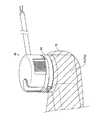
図3に示すように、ロボットアーム21は、清潔区域において使用されるため、ドレープ70により覆われる。ここで、手術室では、手術により切開した部分および医療機器が病原菌や異物などにより汚染されることを防ぐため、清潔操作が行われる。この清潔操作においては、清潔区域および清潔区域以外の区域である汚染区域が設定される。手術部位は、清潔区域に配置される。操作者Oを含む手術チームのメンバーは、手術中、清潔区域に殺菌されている物体のみが位置するよう配慮し、かつ、汚染区域に位置している物体を清潔区域に移動させるときは、この物体に滅菌処理を施す。同様に、操作者Oを含む手術チームのメンバーがその手を汚染区域に位置させたときは、清潔区域に位置している物体に直接接触する前に、手の滅菌処理を行う。清潔区域において用いられる器具は、滅菌処理が行われる、または、滅菌処理されたドレープ70により覆われる。 As shown in FIG. 3, therobot arm 21 is covered by thedrape 70 because it is used in a clean area. Here, in the operating room, a clean operation is performed in order to prevent the incised portion and the medical device from being contaminated by pathogens, foreign substances, and the like. In this cleanup operation, a clean area and a contaminated area other than the clean area are set. The surgical site is located in a clean area. Members of the surgery team, including Operator O, should take care to ensure that only sterilized objects are located in the clean area during surgery, and when moving objects located in the contaminated area to the clean area. Sterilize the object. Similarly, when a member of the surgical team, including Operator O, places his hand in a contaminated area, the hand is sterilized before it comes into direct contact with an object located in a clean area. Instruments used in clean areas are sterilized or covered with a sterilizeddrape 70.

ドレープ70は、ロボットアーム21と、手術器具40との間に配置される。具体的には、ドレープ70は、アダプタ60と、ロボットアーム21との間に配置される。アダプタ60は、ドレープ70を挟み込むようにして、ロボットアーム21に取り付けられる。つまり、アダプタ60は、ロボットアーム21aとの間にドレープ70を挟み込むためのドレープアダプタである。また、アダプタ60には、手術器具40が取り付けられる。ロボットアーム21は、手術器具40のエンドエフェクタ41を駆動させるために、アダプタ60を介して手術器具40に動力を伝達する。 Thedrape 70 is arranged between therobot arm 21 and thesurgical instrument 40. Specifically, thedrape 70 is arranged between theadapter 60 and therobot arm 21. Theadapter 60 is attached to therobot arm 21 so as to sandwich thedrape 70. That is, theadapter 60 is a drape adapter for sandwiching thedrape 70 with therobot arm 21a. Asurgical instrument 40 is attached to theadapter 60. Therobot arm 21 transmits power to thesurgical instrument 40 via theadapter 60 in order to drive theend effector 41 of thesurgical instrument 40.

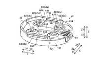
図4に示すように、アダプタ60は、基体61と、複数の駆動伝達部材62と、ガイドレール63と、先行ガイドレール64と、第1電極アレイ65と、アーム係合部66と、を備えている。また、図5に示すように、アダプタ60は、複数のアーム係合穴部67と、複数の位置決孔68とを備えている。駆動伝達部材62は、図4に示すように、Y2方向側に配置された複数の第1駆動伝達部材62aと、Y1方向側に配置された複数の第2駆動伝達部材62bとを含んでいる。また、アダプタ60は、Z2方向側に配置された第1面60aがロボットアーム21aに取り付けられる。また、アダプタ60は、Z1方向側に配置された第2面60bに手術器具40が取り付けられる。 As shown in FIG. 4, theadapter 60 includes abase 61, a plurality ofdrive transmission members 62, aguide rail 63, a leadingguide rail 64, afirst electrode array 65, and anarm engaging portion 66. ing. Further, as shown in FIG. 5, theadapter 60 includes a plurality ofarm engaging holes 67 and a plurality of positioning holes 68. As shown in FIG. 4, thedrive transmission member 62 includes a plurality of firstdrive transmission members 62a arranged on the Y2 direction side and a plurality of seconddrive transmission members 62b arranged on the Y1 direction side. .. Further, in theadapter 60, afirst surface 60a arranged on the Z2 direction side is attached to therobot arm 21a. Further, in theadapter 60, thesurgical instrument 40 is attached to thesecond surface 60b arranged on the Z1 direction side.

図5に示すように、手術器具40のハウジング43のZ2方向側に配置された取付面40aがアダプタ60に取り付けられる。また、手術器具40は、複数の回転部材44と、2つの案内溝45(第1の案内溝45aおよび第2の案内溝45b)と、2つの可動部材46と、先行案内溝47と、第2電極アレイ48とを備えている。回転部材44は、Y2方向側に配置された複数の第1回転部材44aと、Y1方向側に配置された複数の第2回転部材44bとを含んでいる。可動部材46は、ボタン461に接続されている。 As shown in FIG. 5, a mountingsurface 40a arranged on the Z2 direction side of thehousing 43 of thesurgical instrument 40 is mounted on theadapter 60. Further, thesurgical instrument 40 includes a plurality of rotatingmembers 44, two guide grooves 45 (first guide groove 45a andsecond guide groove 45b), twomovable members 46, a leadingguide groove 47, and a first. It includes a two-electrode array 48. The rotatingmember 44 includes a plurality of firstrotating members 44a arranged on the Y2 direction side and a plurality of secondrotating members 44b arranged on the Y1 direction side. Themovable member 46 is connected to thebutton 461.

図4に示すように、ドレープ70は、本体部71と、取付部72とを備えている。本体部71は、フィルム状に形成されている。取付部72は、樹脂成型により形成されている。取付部72は、ロボットアーム21aおよびアダプタ60が係合する部分に貫通口が設けられている。貫通口は、係合する部分ごとに対応するように設けられていてもよい。また、貫通口は、複数の係合する部分に対応するように設けられていてもよい。 As shown in FIG. 4, thedrape 70 includes a main body portion 71 and a mounting portion 72. The main body 71 is formed in a film shape. The mounting portion 72 is formed by resin molding. The mounting portion 72 is provided with a through hole at a portion where therobot arm 21a and theadapter 60 are engaged. The through-hole may be provided so as to correspond to each engaging portion. Further, the through hole may be provided so as to correspond to a plurality of engaging portions.

ロボットアーム21のアダプタ取付面211には、アダプタ60が取り付けられる。また、ロボットアーム21は、回転駆動部212と、係合部213と、ボス214とを備えている。 Theadapter 60 is attached to theadapter attachment surface 211 of therobot arm 21. Further, therobot arm 21 includes arotation driving unit 212, an engagingunit 213, and aboss 214.

図5に示すように、手術器具40の複数の回転部材44は、回転駆動されることにより、エンドエフェクタ41を駆動させる。具体的には、回転部材44とエンドエフェクタ41とは、シャフト42内に通されたワイヤにより接続されている。そして、回転部材44が回転されることにより、ワイヤが引っ張られてエンドエフェクタ41が駆動される。また、回転部材44は、ハウジング43内において、シャフト42とギアにより接続されている。そして、回転部材44が回転されることにより、シャフト42が回転される。 As shown in FIG. 5, the plurality of rotatingmembers 44 of thesurgical instrument 40 are rotationally driven to drive theend effector 41. Specifically, the rotatingmember 44 and theend effector 41 are connected by a wire passed through theshaft 42. Then, when the rotatingmember 44 is rotated, the wire is pulled and theend effector 41 is driven. Further, the rotatingmember 44 is connected to theshaft 42 by a gear in thehousing 43. Then, theshaft 42 is rotated by rotating the rotatingmember 44.

たとえば、回転部材44は、4つ設けられている。1つの回転部材44の回転により、シャフト42が回転される。また、他の3つの回転部材44の回転により、エンドエフェクタ41が駆動される。4つの回転部材44は、X方向に2つ配列され、Y方向に2つ配列されている。 For example, fourrotating members 44 are provided. The rotation of one rotatingmember 44 causes theshaft 42 to rotate. Further, theend effector 41 is driven by the rotation of the other threerotating members 44. Two of the fourrotating members 44 are arranged in the X direction, and two are arranged in the Y direction.

案内溝45は、Y方向に沿って延びるように設けられている。また、案内溝45は、X方向に対向するように2つ設けられている。2つの案内溝45は、略平行に設けられている。2つの案内溝45は、アダプタ60の2つのガイドレール63が挿入されてアダプタ60への取り付けを案内する。案内溝45は、可動部材46がX方向に移動することにより、幅が変化する。つまり、可動部材46が内側に移動することにより、案内溝45の幅が拡張される。また、可動部材46が外側に移動することにより、案内溝45の幅が縮小される。可動部材46は、案内溝45の幅を狭める方向(外側方向)に向けて付勢されている。具体的には、可動部材46は、バネにより付勢されている。可動部材46は、ボタン461を作業者が押すことにより、案内溝45の幅を広げる方向(内側方向)に移動する。 Theguide groove 45 is provided so as to extend along the Y direction. Further, twoguide grooves 45 are provided so as to face each other in the X direction. The twoguide grooves 45 are provided substantially in parallel. Twoguide rails 63 of theadapter 60 are inserted into the twoguide grooves 45 to guide the attachment to theadapter 60. The width of theguide groove 45 changes as themovable member 46 moves in the X direction. That is, the width of theguide groove 45 is expanded by moving themovable member 46 inward. Further, the width of theguide groove 45 is reduced by moving themovable member 46 to the outside. Themovable member 46 is urged in a direction (outward direction) in which the width of theguide groove 45 is narrowed. Specifically, themovable member 46 is urged by a spring. When the operator pushes thebutton 461, themovable member 46 moves in the direction of widening the width of the guide groove 45 (inward direction).

先行案内溝47は、Y方向に沿って延びるように設けられている。また、先行案内溝47は、2つの案内溝45(第1の案内溝45aおよび第2の案内溝45b)の間に設けられている。また、先行案内溝47は、案内溝45と略平行に延びるように形成されている。また、先行案内溝47は、X方向における取付面40aの略中央に設けられている。 The leadingguide groove 47 is provided so as to extend along the Y direction. Further, the leadingguide groove 47 is provided between the two guide grooves 45 (thefirst guide groove 45a and thesecond guide groove 45b). Further, the leadingguide groove 47 is formed so as to extend substantially parallel to theguide groove 45. Further, the leadingguide groove 47 is provided substantially in the center of the mountingsurface 40a in the X direction.

第2電極アレイ48は、アダプタ60の第1電極アレイ65を介してロボットアーム21に接続される。また、第2電極アレイ48は、ハウジング43内に設けられた基板に接続されている。つまり、手術器具40をアダプタ60を介してロボットアーム21に取り付けることにより、手術器具40の基板と、ロボットアーム21とが接続される。ハウジング43内の基板は、手術器具40の種類や手術器具40の使用回数を管理するためなどに用いられる。 Thesecond electrode array 48 is connected to therobot arm 21 via thefirst electrode array 65 of theadapter 60. Further, thesecond electrode array 48 is connected to a substrate provided in thehousing 43. That is, by attaching thesurgical instrument 40 to therobot arm 21 via theadapter 60, the substrate of thesurgical instrument 40 and therobot arm 21 are connected. The substrate in thehousing 43 is used for controlling the type ofsurgical instrument 40 and the number of times thesurgical instrument 40 is used.

図4〜図6に示すように、アダプタ60は、ロボット手術システム100のロボットアーム21aに手術器具40を取り外し可能に接続するために設けられている。基体61は、ロボットアーム21aに取り付けるための第1面60aと、手術器具40の取付面40aが装着される第2面60bと、を含んでいる。アダプタ60は、Z方向にみて、手術器具40のハウジング43と略同じ大きさを有している。具体的には、アダプタ60は、Z方向にみて、ハウジング43と略同じ直径を有する略円形状に形成されている。 As shown in FIGS. 4 to 6, theadapter 60 is provided to removably connect thesurgical instrument 40 to therobot arm 21a of therobotic surgery system 100. Thebase 61 includes afirst surface 60a for mounting on therobot arm 21a and asecond surface 60b on which the mountingsurface 40a of thesurgical instrument 40 is mounted. Theadapter 60 has substantially the same size as thehousing 43 of thesurgical instrument 40 when viewed in the Z direction. Specifically, theadapter 60 is formed in a substantially circular shape having substantially the same diameter as thehousing 43 when viewed in the Z direction.

駆動伝達部材62は、基体61に回転可能に設けられている。具体的には、駆動伝達部材62は、Z方向に延びる回転軸線を中心に回転可能に設けられている。駆動伝達部材62は、ロボットアーム21aの回転駆動部212の駆動力を、手術器具40の回転部材44に伝達する。駆動伝達部材62は、手術器具40の回転部材44に対応するように複数設けられている。また、複数の駆動伝達部材62は、手術器具40の回転部材44に対応する位置に各々配置されている。 Thedrive transmission member 62 is rotatably provided on thebase 61. Specifically, thedrive transmission member 62 is rotatably provided about a rotation axis extending in the Z direction. Thedrive transmission member 62 transmits the driving force of therotation drive unit 212 of therobot arm 21a to therotation member 44 of thesurgical instrument 40. A plurality ofdrive transmission members 62 are provided so as to correspond to therotating members 44 of thesurgical instrument 40. Further, the plurality ofdrive transmission members 62 are respectively arranged at positions corresponding to therotating members 44 of thesurgical instrument 40.

ガイドレール63は、第2面60bに設けられている。また、ガイドレール63は、Y方向に沿って延びるように設けられている。また、ガイドレール63は、X方向に対向するように2つ設けられている。2つのガイドレール63(第1のガイドレール63aおよび第2のガイドレール63b)は、略平行に設けられている。また、第1のガイドレール63aおよび第2のガイドレール63bは、手術器具40の取付面40aに略平行に設けられた第1の案内溝45aおよび第2の案内溝45bにそれぞれ対応するように設けられている。第2面60bの第1のガイドレール63aおよび第2のガイドレール63bは、第1のガイドレール63aおよび第2のガイドレール63bのそれぞれの一端634(Y2方向側の端部)と、取付面40aの第1の案内溝45aおよび第2の案内溝45bのそれぞれの一端452(Y1方向側の端部)とを対応させてスライドさせることにより、複数の駆動伝達部材62の各々と、取付面40aに設けられた複数の回転部材44の各々とが対応するように手術器具40を案内するように構成されている。 Theguide rail 63 is provided on thesecond surface 60b. Further, theguide rail 63 is provided so as to extend along the Y direction. Further, twoguide rails 63 are provided so as to face each other in the X direction. The two guide rails 63 (thefirst guide rail 63a and thesecond guide rail 63b) are provided substantially in parallel. Further, thefirst guide rail 63a and thesecond guide rail 63b correspond to thefirst guide groove 45a and thesecond guide groove 45b provided substantially parallel to the mountingsurface 40a of thesurgical instrument 40, respectively. It is provided. Thefirst guide rail 63a and thesecond guide rail 63b of thesecond surface 60b have one end 634 (end on the Y2 direction side) of each of thefirst guide rail 63a and thesecond guide rail 63b, and a mounting surface. By sliding one end 452 (the end on the Y1 direction side) of each of thefirst guide groove 45a and thesecond guide groove 45b of 40a in correspondence with each other, each of the plurality ofdrive transmission members 62 and the mounting surface Thesurgical instrument 40 is configured to guide thesurgical instrument 40 so as to correspond to each of the plurality of rotatingmembers 44 provided on the 40a.

これにより、手術器具40の取付面40aの案内溝45に対応するように、手術器具40の取付面40aが装着される第2面60bに第1のガイドレール63aおよび第2のガイドレール63bを形成することができるので、平面視において(Z方向に見て)、第1のガイドレール63aおよび第2のガイドレール63bを手術器具40の取付面40aに対して内側に形成することができる。その結果、アダプタ60を手術器具40の取付面40a以下の大きさに形成することができるので、ロボット手術システム100のロボットアーム21aに手術器具40を取り外し可能に接続するためのアダプタ60を小型化することができる。 As a result, thefirst guide rail 63a and thesecond guide rail 63b are attached to thesecond surface 60b on which the mountingsurface 40a of thesurgical instrument 40 is mounted so as to correspond to theguide groove 45 of the mountingsurface 40a of thesurgical instrument 40. Since it can be formed, thefirst guide rail 63a and thesecond guide rail 63b can be formed inside the mountingsurface 40a of thesurgical instrument 40 in a plan view (when viewed in the Z direction). As a result, theadapter 60 can be formed to have a size equal to or smaller than the mountingsurface 40a of thesurgical instrument 40. can do.

また、第2面60bの第1のガイドレール63aおよび第2のガイドレール63bは、第2部材622の第1部材621に対する移動方向(Z方向)と交差する方向(Y方向)に、手術器具40の第1の案内溝45aおよび第2の案内溝45bを案内するように構成されている。つまり、アダプタ60に対する手術器具40のスライド挿入方向は、手術器具40のシャフト42が延びる方向と略平行である。これにより、スライド挿入方向がシャフト42の延びる方向と交差する場合と異なり、アダプタ60に対して手術器具40をスライドして脱着する場合に、シャフト42を移動させるために必要なスペースを、シャフト42の延びる方向のみに設ければよい。つまり、シャフト42の延びる方向と交差する方向にシャフト42を移動させるためのスペースを大きくとる必要がない。 Further, thefirst guide rail 63a and thesecond guide rail 63b on thesecond surface 60b are surgical instruments in a direction (Y direction) intersecting the moving direction (Z direction) of thesecond member 622 with respect to thefirst member 621. It is configured to guide thefirst guide groove 45a and thesecond guide groove 45b of the 40. That is, the slide insertion direction of thesurgical instrument 40 with respect to theadapter 60 is substantially parallel to the direction in which theshaft 42 of thesurgical instrument 40 extends. As a result, unlike the case where the slide insertion direction intersects the extending direction of theshaft 42, the space required for moving theshaft 42 when thesurgical instrument 40 is slid and attached to theadapter 60 is provided to theshaft 42. It suffices to be provided only in the extending direction of. That is, it is not necessary to take a large space for moving theshaft 42 in the direction intersecting the extending direction of theshaft 42.

先行ガイドレール64は、第2面60bに設けられている。また、先行ガイドレール64は、Y方向に沿って延びるように設けられている。また、先行ガイドレール64は、第1のガイドレール63aおよび第2のガイドレール63bの間に設けられている。また、先行ガイドレール64は、第1のガイドレール63aおよび第2のガイドレール63bと略平行に延びるように形成されている。また、先行ガイドレール64は、X方向における第2面60bの略中央に設けられている。また、先行ガイドレール64は、取付面40aに設けられた先行案内溝47に対応して設けられている。つまり、先行ガイドレール64は、第1のガイドレール63aおよび第2のガイドレール63bよりも先行して手術器具40を案内する。これにより、第1のガイドレール63aおよび第2のガイドレール63bの間に設けられた先行ガイドレール64の案内により、第1のガイドレール63aおよび第2のガイドレール63bを第1の案内溝45aおよび第2の案内溝45bに容易に導くことができるので、手術器具40をアダプタ60に容易に取り付けることができる。 The leadingguide rail 64 is provided on thesecond surface 60b. Further, the leadingguide rail 64 is provided so as to extend along the Y direction. Further, the leadingguide rail 64 is provided between thefirst guide rail 63a and thesecond guide rail 63b. Further, the leadingguide rail 64 is formed so as to extend substantially parallel to thefirst guide rail 63a and thesecond guide rail 63b. Further, the leadingguide rail 64 is provided substantially in the center of thesecond surface 60b in the X direction. Further, the leadingguide rail 64 is provided corresponding to theleading guide groove 47 provided on the mountingsurface 40a. That is, the leadingguide rail 64 guides thesurgical instrument 40 ahead of thefirst guide rail 63a and thesecond guide rail 63b. As a result, thefirst guide rail 63a and thesecond guide rail 63b are moved into thefirst guide groove 45a by the guidance of theleading guide rail 64 provided between thefirst guide rail 63a and thesecond guide rail 63b. And because it can be easily guided to thesecond guide groove 45b, thesurgical instrument 40 can be easily attached to theadapter 60.

また、先行ガイドレール64は、アダプタ60に対する手術器具40のスライド挿入方向上流側(Y2方向側)が先細り形状に形成されている。具体的には、先行ガイドレール64は、Y2方向側の端部がX方向の幅が先細る形状に形成されている。また、先行ガイドレール64は、Y2方向側の端部がZ方向の高さが先細る形状に形成されている。これにより、先細り形状の部分により先行ガイドレール64を先行案内溝47に容易に導くことができる。 Further, the leadingguide rail 64 is formed in a tapered shape on the upstream side (Y2 direction side) of thesurgical instrument 40 with respect to theadapter 60 in the slide insertion direction. Specifically, the leadingguide rail 64 is formed so that the end portion on the Y2 direction side has a tapered width in the X direction. Further, the leadingguide rail 64 is formed so that the end portion on the Y2 direction side is tapered in height in the Z direction. As a result, the leadingguide rail 64 can be easily guided to theleading guide groove 47 by the tapered portion.

第1電極アレイ65は、手術器具40の第2電極アレイ48とロボットアーム21とに接続される。第1電極アレイ65は、図8に示すように、複数の電極651と、溝652とを含んでいる。電極651は、基体61を貫通するようにZ方向に延びるように配置されている。溝652は、第2面60bに設けられている。また、溝652は、手術器具40の取付面40aの第2電極アレイ48に設けられた突出部482(図11参照)を受け入れる。つまり、アダプタ60に手術器具40が取り付けられた場合に、溝652に突出部482が嵌り込む。これにより、手術器具40がアダプタ60から取り外されている状態においても、突出部482および溝652により、作業者が第1電極アレイ65および第2電極アレイ48に触れることを防止することができる。また、手術器具40をアダプタ60に取り付ける場合に、突出部482を溝652により受け入れて、第1電極アレイ65と第2電極アレイ48とを接続することができる。 Thefirst electrode array 65 is connected to thesecond electrode array 48 of thesurgical instrument 40 and therobot arm 21. As shown in FIG. 8, thefirst electrode array 65 includes a plurality ofelectrodes 651 and agroove 652. Theelectrode 651 is arranged so as to extend in the Z direction so as to penetrate thesubstrate 61. Thegroove 652 is provided on thesecond surface 60b. Further, thegroove 652 receives a protrusion 482 (see FIG. 11) provided in thesecond electrode array 48 on the mountingsurface 40a of thesurgical instrument 40. That is, when thesurgical instrument 40 is attached to theadapter 60, theprotrusion 482 fits into thegroove 652. Thereby, even when thesurgical instrument 40 is removed from theadapter 60, theprotrusion 482 and thegroove 652 can prevent the operator from touching thefirst electrode array 65 and thesecond electrode array 48. Further, when thesurgical instrument 40 is attached to theadapter 60, the protrudingportion 482 can be received by thegroove 652 to connect thefirst electrode array 65 and thesecond electrode array 48.

アーム係合部66は、ロボットアーム21の係合部213に係合する。具体的には、アーム係合部66は、第1面60aに設けられたアーム係合穴部67に挿入された係合部213と係合する。また、アーム係合部66は、Y方向に移動可能である。アーム係合部66は、付勢部材によりY1方向に付勢されている。アーム係合部66は、Y1方向に移動されることにより、係合部213と係合する。一方アーム係合部66は、Y2方向に移動されることにより、係合部213との係合が解除される。 Thearm engaging portion 66 engages with the engagingportion 213 of therobot arm 21. Specifically, thearm engaging portion 66 engages with the engagingportion 213 inserted into the arm engaginghole portion 67 provided on thefirst surface 60a. Further, thearm engaging portion 66 can be moved in the Y direction. Thearm engaging portion 66 is urged in the Y1 direction by the urging member. Thearm engaging portion 66 engages with the engagingportion 213 by being moved in the Y1 direction. On the other hand, thearm engaging portion 66 is disengaged from the engagingportion 213 by being moved in the Y2 direction.

アーム係合穴部67は、複数設けられている。つまり、アダプタ60は、複数個所の係合により、ロボットアーム21に固定される。アーム係合穴部67は、たとえば、5つ設けられている。また、複数のアーム係合穴部67は、第1面60aの周方向に沿って、均等に設けられている。 A plurality ofarm engaging holes 67 are provided. That is, theadapter 60 is fixed to therobot arm 21 by engaging at a plurality of places. For example, fivearm engaging holes 67 are provided. Further, the plurality ofarm engaging holes 67 are evenly provided along the circumferential direction of thefirst surface 60a.

位置決孔68は、第1面60aに設けられている。位置決孔68は、ロボットアーム21のボス214が嵌り込む。位置決孔68は、複数設けられている。位置決孔68は、第1面60aのY1方向側の端部近傍に設けられている。 Thepositioning hole 68 is provided on thefirst surface 60a. Theboss 214 of therobot arm 21 fits into thepositioning hole 68. A plurality of positioning holes 68 are provided. Thepositioning hole 68 is provided near the end of thefirst surface 60a on the Y1 direction side.

図7に示すように、駆動伝達部材62は、第1部材621と、付勢部材623を介して第1部材621に対して移動可能に設けられた第2部材622と、を含んでいる。第1部材621は、第2部材622が嵌り込む凹部621aと、第2部材622に係合する係合部621bとを有している。第2部材622は、付勢部材623が収容される凹部622aと、第1部材621に係合する係合部622bとを有している。第1部材621と、第2部材622とは、付勢部材623を間に挟んだ状態でZ方向に篏合している。第1部材621は、第2面60b側(Z1方向側)に配置されている。第2部材622は、第1面60a側(Z2方向側)に配置されている。付勢部材623は、第1部材621を第2部材622に対してZ1方向側に付勢している。付勢部材623は、たとえば、バネにより構成されている。 As shown in FIG. 7, thedrive transmission member 62 includes afirst member 621 and asecond member 622 movably provided with respect to thefirst member 621 via an urgingmember 623. Thefirst member 621 has arecess 621a into which thesecond member 622 fits, and an engagingportion 621b that engages with thesecond member 622. Thesecond member 622 has arecess 622a in which the urgingmember 623 is housed, and an engagingportion 622b that engages with thefirst member 621. Thefirst member 621 and thesecond member 622 are aligned in the Z direction with the urgingmember 623 sandwiched between them. Thefirst member 621 is arranged on thesecond surface 60b side (Z1 direction side). Thesecond member 622 is arranged on thefirst surface 60a side (Z2 direction side). The urgingmember 623 urges thefirst member 621 toward the Z1 direction with respect to thesecond member 622. The urgingmember 623 is composed of, for example, a spring.

第2部材622は、Z方向において、第1面60aと面一に配置されている。また、第2部材622は、Z方向において、基体61に対して移動されないように配置されている。第1部材621は、Z方向において、基体61に対して移動可能に配置されている。これにより、手術器具40を第1のガイドレール63aおよび第2のガイドレール63bに沿って案内してアダプタ60に取り付ける場合に、手術器具40の移動の妨げにならないように駆動伝達部材62の第1部材621をZ方向にくぼむように移動させることができる。 Thesecond member 622 is arranged flush with thefirst surface 60a in the Z direction. Further, thesecond member 622 is arranged so as not to be moved with respect to thesubstrate 61 in the Z direction. Thefirst member 621 is movably arranged with respect to thesubstrate 61 in the Z direction. As a result, when thesurgical instrument 40 is guided along thefirst guide rail 63a and thesecond guide rail 63b and attached to theadapter 60, thedrive transmission member 62 is set so as not to interfere with the movement of thesurgical instrument 40. Onemember 621 can be moved so as to be recessed in the Z direction.

また、第1部材621は、第2部材622がZ方向の回転軸線を中心に回転することに伴って、回転されるように構成されている。具体的には、第1部材621の内周部に設けられた係合部621bと、第2部材622の外周部に設けられた係合部622bとが、係合するように構成されている。第1部材621の係合部621bは、凹部621aから内側に突出するように形成されている。第2部材622の係合部622bは、第2部材622の外周部から内側に凹むように形成されている。第1部材621の係合部621bと、第2部材622の係合部622bとは、第1部材621が第2部材622に対してZ方向に移動したとしても、互いに係合するように構成されている。つまり、第2部材622に対する第1部材621のZ方向における位置に関わらず、第1部材621は、第2部材622とともに回転されるように構成されている。これにより、第2部材622がロボットアーム21の回転駆動部212の回転により回転されると、第1部材621も回転される。その結果、第1部材621に係合する手術器具40の回転部材44に、ロボットアーム21の回転駆動部212の回転が伝達される。 Further, thefirst member 621 is configured to be rotated as thesecond member 622 rotates about the rotation axis in the Z direction. Specifically, the engagingportion 621b provided on the inner peripheral portion of thefirst member 621 and the engagingportion 622b provided on the outer peripheral portion of thesecond member 622 are configured to engage with each other. .. The engagingportion 621b of thefirst member 621 is formed so as to project inward from therecess 621a. The engagingportion 622b of thesecond member 622 is formed so as to be recessed inward from the outer peripheral portion of thesecond member 622. The engagingportion 621b of thefirst member 621 and the engagingportion 622b of thesecond member 622 are configured to engage with each other even if thefirst member 621 moves in the Z direction with respect to thesecond member 622. Has been done. That is, thefirst member 621 is configured to rotate together with thesecond member 622 regardless of the position of thefirst member 621 with respect to thesecond member 622 in the Z direction. As a result, when thesecond member 622 is rotated by the rotation of therotation drive unit 212 of therobot arm 21, thefirst member 621 is also rotated. As a result, the rotation of therotation drive unit 212 of therobot arm 21 is transmitted to therotation member 44 of thesurgical instrument 40 that engages with thefirst member 621.

図8および図9に示すように、ガイドレール63は、レール部631と、張出部632と、爪部633とを含んでいる。レール部631は、Y方向に延びるように形成されている。レール部631は、手術器具40の案内溝45に入り込んで、アダプタ60に対する手術器具40の移動をガイドする。 As shown in FIGS. 8 and 9, theguide rail 63 includes arail portion 631, an overhangingportion 632, and aclaw portion 633. Therail portion 631 is formed so as to extend in the Y direction. Therail portion 631 enters theguide groove 45 of thesurgical instrument 40 and guides the movement of thesurgical instrument 40 with respect to theadapter 60.

張出部632は、レール部631からX方向に張り出すように形成されている。具体的には、第1のガイドレール63aおよび第2のガイドレール63bのうち、X1方向側のガイドレール63の張出部632は、レール部631に対してX1方向側に配置されている。また、第1のガイドレール63aおよび第2のガイドレール63bのうち、X2方向側のガイドレール63の張出部632は、レール部631に対してX2方向側に配置されている。 The overhangingportion 632 is formed so as to overhang from therail portion 631 in the X direction. Specifically, of thefirst guide rail 63a and thesecond guide rail 63b, the overhangingportion 632 of theguide rail 63 on the X1 direction side is arranged on the X1 direction side with respect to therail portion 631. Further, of thefirst guide rail 63a and thesecond guide rail 63b, the overhangingportion 632 of theguide rail 63 on the X2 direction side is arranged on the X2 direction side with respect to therail portion 631.

爪部633は、レール部631からX方向に張り出すように形成されている。具体的には、第1のガイドレール63aおよび第2のガイドレール63bのうち、X1方向側のガイドレール63の爪部633は、レール部631に対してX2方向側に配置されている。また、第1のガイドレール63aおよび第2のガイドレール63bのうち、X2方向側のガイドレール63の爪部633は、レール部631に対してX1方向側に配置されている。つまり、張出部632は、レール部631に対して、爪部633の反対側に設けられている。張出部632は、レール部631に対してX方向における外側に配置されている。爪部633は、レール部631に対してX方向における内側に配置されている。 Theclaw portion 633 is formed so as to project from therail portion 631 in the X direction. Specifically, of thefirst guide rail 63a and thesecond guide rail 63b, theclaw portion 633 of theguide rail 63 on the X1 direction side is arranged on the X2 direction side with respect to therail portion 631. Further, of thefirst guide rail 63a and thesecond guide rail 63b, theclaw portion 633 of theguide rail 63 on the X2 direction side is arranged on the X1 direction side with respect to therail portion 631. That is, the overhangingportion 632 is provided on the opposite side of theclaw portion 633 with respect to therail portion 631. The overhangingportion 632 is arranged outside therail portion 631 in the X direction. Theclaw portion 633 is arranged inside therail portion 631 in the X direction.

張出部632は、手術器具40の案内溝45に設けられた係合溝451(図10および図11参照)に係合する。これにより、張出部632が係合溝451に係合されることによって、アダプタ60に対して手術器具40をより安定して固定することができる。つまり、張出部632が係合溝451に係合することにより、アダプタ60に対して手術器具40がZ方向に抜けないように接続される。 The overhangingportion 632 engages with an engaging groove 451 (see FIGS. 10 and 11) provided in theguide groove 45 of thesurgical instrument 40. As a result, the overhangingportion 632 is engaged with the engaginggroove 451 so that thesurgical instrument 40 can be more stably fixed to theadapter 60. That is, by engaging the overhangingportion 632 with the engaginggroove 451 so that thesurgical instrument 40 is connected to theadapter 60 so as not to come off in the Z direction.

爪部633は、手術器具40の案内溝45に設けられた係合穴462(図10および図11参照)に係合する。具体的には、爪部633は、案内溝45を形成する可動部材46の側壁に設けられた係合穴462に係合する。これにより、爪部633が係合穴462に係合されることによって、ガイドレール63により案内した手術器具40をアダプタ60に対して位置決めして固定することができる。つまり、爪部633が係合穴462に係合することにより、手術器具40がアダプタ60に対してY方向に位置決めされるとともに、アダプタ60に対して手術器具40がY方向に抜けないように固定(ロック)される。また、爪部633は、図9に示すように、X方向に沿って傾斜するように形成されている。 Theclaw portion 633 engages with an engaging hole 462 (see FIGS. 10 and 11) provided in theguide groove 45 of thesurgical instrument 40. Specifically, theclaw portion 633 engages with the engaginghole 462 provided in the side wall of themovable member 46 forming theguide groove 45. As a result, theclaw portion 633 is engaged with the engaginghole 462, so that thesurgical instrument 40 guided by theguide rail 63 can be positioned and fixed with respect to theadapter 60. That is, by engaging theclaw portion 633 with the engaginghole 462, thesurgical instrument 40 is positioned in the Y direction with respect to theadapter 60, and thesurgical instrument 40 does not come off with respect to theadapter 60 in the Y direction. It is fixed (locked). Further, as shown in FIG. 9, theclaw portion 633 is formed so as to be inclined along the X direction.

図8に示すように、複数の駆動伝達部材62は、それぞれ、手術器具40の取付面40aに設けられた対応する回転部材44に係合する係合部624を含んでいる。係合部624は、複数の駆動伝達部材62のうちスライド挿入方向上流側(Y2方向側)に位置する第1駆動伝達部材62aに設けられた第1係合部624aと、複数の駆動伝達部材62のうちスライド挿入方向下流側(Y1方向側)に位置する第2駆動伝達部材62bに設けられた第2係合部624bとを含んでいる。第1係合部624aと、第2係合部624bとは、互いに異なる形状を有している。これにより、アダプタ60に対する手術器具40のスライドの途中で、第1駆動伝達部材62aと第2駆動伝達部材62bに対応する回転部材44とが互いに係合して引っかかるのを抑制することができるので、アダプタ60に対して手術器具40をスムーズに取り付けることができる。 As shown in FIG. 8, each of the plurality ofdrive transmission members 62 includes an engagingportion 624 that engages with a corresponding rotatingmember 44 provided on the mountingsurface 40a of thesurgical instrument 40. The engagingportion 624 includes a first engagingportion 624a provided on the firstdrive transmission member 62a located on the upstream side (Y2 direction side) of the plurality ofdrive transmission members 62 in the slide insertion direction, and the plurality of drive transmission members. Of 62, the secondengaging portion 624b provided on the seconddrive transmission member 62b located on the downstream side (Y1 direction side) in the slide insertion direction is included. The firstengaging portion 624a and the secondengaging portion 624b have different shapes from each other. As a result, it is possible to prevent the firstdrive transmission member 62a and the rotatingmember 44 corresponding to the seconddrive transmission member 62b from engaging with each other and being caught in the middle of sliding thesurgical instrument 40 with respect to theadapter 60. , Thesurgical instrument 40 can be smoothly attached to theadapter 60.

つまり、第1係合部624aは、第2係合部624bに係合する回転部材44が係合しない形状を有している。これにより、アダプタ60に対する手術器具40のスライドの途中で、第1駆動伝達部材62aと第2駆動伝達部材62bに対応する回転部材44とが互いに係合して引っかかるのをより確実に抑制することができる。 That is, the first engagingportion 624a has a shape in which the rotatingmember 44 that engages with the secondengaging portion 624b does not engage. As a result, it is possible to more reliably prevent the firstdrive transmission member 62a and the rotatingmember 44 corresponding to the seconddrive transmission member 62b from being engaged with each other and being caught in the middle of sliding thesurgical instrument 40 with respect to theadapter 60. Can be done.

具体的には、第1駆動伝達部材62aの第2面60b側には、第1係合部624aとして、第1凹部625および第2凹部626が独立して形成されている。また、第2駆動伝達部材62bの第2面60b側には、第2係合部624bとして、第1凹部625および第2凹部626が第3凹部627によりつながった形状の1つの凹部が形成されている。図10に示すように、手術器具40の取付面40aに設けられた複数の回転部材44のうち第1駆動伝達部材62aに係合する第1回転部材44aには、第1凹部625および第2凹部626に挿入される第1突起部441および第2突起部442を有している。つまり、第1凹部625には、第1突起部441が係合する。また、第2凹部626には、第2突起部442が係合する。 Specifically, afirst recess 625 and asecond recess 626 are independently formed as the first engagingportion 624a on thesecond surface 60b side of the firstdrive transmission member 62a. Further, on thesecond surface 60b side of the seconddrive transmission member 62b, one recess having a shape in which thefirst recess 625 and thesecond recess 626 are connected by thethird recess 627 is formed as the secondengaging portion 624b. ing. As shown in FIG. 10, among the plurality of rotatingmembers 44 provided on the mountingsurface 40a of thesurgical instrument 40, the first rotatingmember 44a that engages with the firstdrive transmission member 62a has afirst recess 625 and a second. It has afirst protrusion 441 and asecond protrusion 442 that are inserted into therecess 626. That is, thefirst protrusion 441 engages with thefirst recess 625. Further, thesecond protrusion 442 engages with thesecond recess 626.

手術器具40の取付面40aに設けられた複数の回転部材44のうち第2駆動伝達部材62bに係合する第2回転部材44bは、1つの凹部に挿入される第1突起部441と、第2突起部442と、第1突起部441および第2突起部442の間に配置された第3突起部443と、を有している。つまり、第1凹部625には、第1突起部441が係合する。また、第2凹部626には、第2突起部442が係合する。また、第3凹部627には、第3突起部443が係合する。これにより、第1凹部625および第2凹部626を独立して設けるか、第1凹部625および第2凹部626をつなげて1つの凹部にするかにより、第1係合部624aおよび第2係合部624bの形状を容易に互いに異なるように形成することができる。また、第1突起部441および第2突起部442を構成する部品を共通にして、第3突起部443の有無により、第1回転部材44aおよび第2回転部材44bの係合部分を互いに異なる形状に形成することができるので、部品の種類が増加するのを抑制することができる。 Of the plurality of rotatingmembers 44 provided on the mountingsurface 40a of thesurgical instrument 40, the second rotatingmember 44b that engages with the seconddrive transmission member 62b has afirst protrusion 441 inserted into one recess and a first It has twoprotrusions 442 and athird protrusion 443 arranged between thefirst protrusion 441 and thesecond protrusion 442. That is, thefirst protrusion 441 engages with thefirst recess 625. Further, thesecond protrusion 442 engages with thesecond recess 626. Further, thethird protrusion 443 engages with thethird recess 627. As a result, depending on whether thefirst recess 625 and thesecond recess 626 are provided independently, or thefirst recess 625 and thesecond recess 626 are connected to form one recess, the first engagingportion 624a and the second engagingportion 624a and the second engaging portion are engaged. The shapes of theportions 624b can be easily formed so as to be different from each other. Further, the parts constituting thefirst protrusion 441 and thesecond protrusion 442 are shared, and the engaging portions of the first rotatingmember 44a and the second rotatingmember 44b have different shapes depending on the presence or absence of thethird protrusion 443. Since it can be formed in, it is possible to suppress an increase in the types of parts.

図10および図11に示すように、手術器具40の取付面40aの案内溝45には、係合溝451が設けられている。係合溝451は、案内溝45に沿って、Y方向に延びるように形成されている。係合溝451には、アダプタ60の第2面60bに設けられたガイドレール63の張出部632が係合する。 As shown in FIGS. 10 and 11, theguide groove 45 on the mountingsurface 40a of thesurgical instrument 40 is provided with anengagement groove 451. Theengagement groove 451 is formed so as to extend in the Y direction along theguide groove 45. The overhangingportion 632 of theguide rail 63 provided on thesecond surface 60b of theadapter 60 engages with the engaginggroove 451.

案内溝45を形成する可動部材46の側壁には、係合穴462が設けられている。係合穴462には、アダプタ60の第2面60bに設けられたガイドレール63の爪部633が係合する。また、可動部材46を、X方向における内側方向に移動させることにより、爪部633の係合穴462への係合が解除される。また、可動部材46を、X方向における内側方向に移動させることにより、駆動伝達部材62がZ2方向に押されて、駆動伝達部材62と、回転部材44との係合が解除される。この状態で、手術器具40をアダプタ60に対してY2方向にスライドさせることにより、手術器具40をアダプタ60から取り外すことができる。 Anengaging hole 462 is provided on the side wall of themovable member 46 forming theguide groove 45. Theclaw portion 633 of theguide rail 63 provided on thesecond surface 60b of theadapter 60 engages with theengagement hole 462. Further, by moving themovable member 46 inward in the X direction, the engagement of theclaw portion 633 with theengagement hole 462 is released. Further, by moving themovable member 46 inward in the X direction, thedrive transmission member 62 is pushed in the Z2 direction, and the engagement between thedrive transmission member 62 and the rotatingmember 44 is released. In this state, thesurgical instrument 40 can be removed from theadapter 60 by sliding thesurgical instrument 40 with respect to theadapter 60 in the Y2 direction.

手術器具40の取付面40aの第2電極アレイ48は、複数の電極481と、突出部482とを含んでいる。複数の電極481は、それぞれ、アダプタ60の第1電極アレイ65の複数の電極651と接続される。突出部482は、各々の電極481に対してX方向の両側に配置されている。突出部482は、電極481に手などが触れるのを防止するために設けられている。具体的には、電極481を挟み込む突出部482の間隔は、指の大きさよりも十分に小さい。また、突出部482は、Z方向において、電極481よりも大きく突出している。 Thesecond electrode array 48 on the mountingsurface 40a of thesurgical instrument 40 includes a plurality ofelectrodes 481 and aprotrusion 482. Each of the plurality ofelectrodes 481 is connected to a plurality ofelectrodes 651 of thefirst electrode array 65 of theadapter 60. Theprotrusions 482 are arranged on both sides in the X direction with respect to eachelectrode 481. Theprotrusion 482 is provided to prevent theelectrode 481 from being touched by a hand or the like. Specifically, the distance between theprotrusions 482 that sandwich theelectrode 481 is sufficiently smaller than the size of a finger. Further, the protrudingportion 482 protrudes more than theelectrode 481 in the Z direction.

(ロボットアームへの手術器具の取り付け)
図12〜図14を参照して、第1実施形態によるロボットアーム21aへの手術器具40の取り付けについて説明する。
(Attachment of surgical instruments to the robot arm)
The attachment of thesurgical instrument 40 to therobot arm 21a according to the first embodiment will be described with reference to FIGS. 12 to 14.

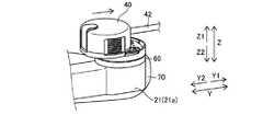
図12に示すように、ロボットアーム21aをドレープ70で覆った状態で、ロボットアーム21aにアダプタ60を取り付ける。アダプタ60は、ロボットアーム21aに対してZ方向に移動させて、ロボットアーム21aに取り付けられる。図13および図14に示すように、ロボットアーム21aに取り付けられたアダプタ60に対して手術器具40を取り付ける。手術器具40は、アダプタ60の先行ガイドレール64および第1のガイドレール63aおよび第2のガイドレール63bに沿ってY方向に移動させて、アダプタ60に取り付けられる。これにより、手術器具40がアダプタ60を介してロボットアーム21aに取り付けられる。 As shown in FIG. 12, theadapter 60 is attached to therobot arm 21a with therobot arm 21a covered with thedrape 70. Theadapter 60 is moved in the Z direction with respect to therobot arm 21a and attached to therobot arm 21a. As shown in FIGS. 13 and 14, thesurgical instrument 40 is attached to theadapter 60 attached to therobot arm 21a. Thesurgical instrument 40 is attached to theadapter 60 by being moved in the Y direction along the leadingguide rail 64 and thefirst guide rail 63a and thesecond guide rail 63b of theadapter 60. As a result, thesurgical instrument 40 is attached to therobot arm 21a via theadapter 60.

手術器具40をロボットアーム21aから取り外す場合は、手術器具40の可動部材46のボタン461を押しながら、手術器具40をY2方向にスライド移動させることにより、手術器具40がアダプタ60から外される。 When thesurgical instrument 40 is removed from therobot arm 21a, thesurgical instrument 40 is removed from theadapter 60 by sliding thesurgical instrument 40 in the Y2 direction while pressing thebutton 461 of themovable member 46 of thesurgical instrument 40.

[第2実施形態]
次に、図15〜図26を参照して、本発明の第2実施形態について説明する。この第2実施形態では、第1実施形態のアダプタに先行ガイド部をさらに設けらた構成の例について説明する。
[Second Embodiment]
Next, a second embodiment of the present invention will be described with reference to FIGS. 15 to 26. In this second embodiment, an example of a configuration in which the adapter of the first embodiment is further provided with a leading guide portion will be described.

ここで、第2実施形態のアダプタ60は、図15および図16に示すように、先行ガイド部69が設けられている。先行ガイド部69は、第1のガイドレール63aおよび第2のガイドレール63bの延びる方向と平行な方向(Y方向)に沿って基体61から突出するように形成されている。また、先行ガイド部69は、第1のガイドレール63aおよび第2のガイドレール63bよりも先行して手術器具40を案内する。これにより、基体61から突出するように設けられた先行ガイド部69の案内により、第1のガイドレール63aおよび第2のガイドレール63bを第1の案内溝45aおよび第2の案内溝45bに容易に導くことができるので、手術器具40をアダプタ60に容易に取り付けることができる。また、基体31から突出するように先行ガイド部69を設けることにより、アダプタ60に対する手術器具40の取り付け方向および取付位置を容易に認識することができる。 Here, theadapter 60 of the second embodiment is provided with aleading guide portion 69 as shown in FIGS. 15 and 16. The leadingguide portion 69 is formed so as to project from thesubstrate 61 along a direction (Y direction) parallel to the extending direction of thefirst guide rail 63a and thesecond guide rail 63b. Further, the leadingguide unit 69 guides thesurgical instrument 40 ahead of thefirst guide rail 63a and thesecond guide rail 63b. As a result, thefirst guide rail 63a and thesecond guide rail 63b can be easily moved to thefirst guide groove 45a and thesecond guide groove 45b by the guidance of theleading guide portion 69 provided so as to project from thebase 61. Thesurgical instrument 40 can be easily attached to theadapter 60 because it can be guided to. Further, by providing theleading guide portion 69 so as to protrude from the base 31, the attachment direction and attachment position of thesurgical instrument 40 with respect to theadapter 60 can be easily recognized.

また、先行ガイド部69は、手術器具40の取付面40aから第2面60b側に突出する突出部49を第1のガイドレール63aおよび第2のガイドレール63bの延びる方向(Y方向)にガイドするように構成されている。これにより、手術器具40の取付面40aに設けられた突出部49を先行ガイド部69に沿ってスライドさせることにより、手術器具40をアダプタ60の取り付け位置に容易に導くことができる。 Further, the leadingguide portion 69 guides the protrudingportion 49 projecting from the mountingsurface 40a of thesurgical instrument 40 toward thesecond surface 60b in the extending direction (Y direction) of thefirst guide rail 63a and thesecond guide rail 63b. It is configured to do. As a result, thesurgical instrument 40 can be easily guided to the attachment position of theadapter 60 by sliding the protrudingportion 49 provided on theattachment surface 40a of thesurgical instrument 40 along the leadingguide portion 69.

手術器具40の突出部49は、図15に示すように、取付面40aのY2方向の端部近傍に一対設けられている。また、一対の突出部49は、X方向に所定の間隔を隔てて配置されている。また、一対の突出部49は、第2電極アレイ48を挟み込むように配置されている。 As shown in FIG. 15, a pair of protrudingportions 49 of thesurgical instrument 40 are provided near the ends of the mountingsurface 40a in the Y2 direction. Further, the pair of protrudingportions 49 are arranged at predetermined intervals in the X direction. Further, the pair of projectingportions 49 are arranged so as to sandwich thesecond electrode array 48.

また、基体61の第2面60bは、取付面40aの突出部49が係合する取付係合部611を有している。これにより、取付係合部611に係合する突出部49を先行ガイド部69により案内することができるので、案内するための部材を手術器具に別途設ける必要がない。具体的には、取付係合部611は、図16に示すように、基体61の第2面60bのY2方向の端部近傍に一対設けられている。また、一対の取付係合部611は、X方向に所定の間隔を隔てて配置されている。また、一対の取付係合部611は、第1電極アレイ65を挟み込むように配置されている。 Further, thesecond surface 60b of thebase 61 has a mountingengaging portion 611 to which the protrudingportion 49 of the mountingsurface 40a engages. As a result, the protrudingportion 49 that engages with the mountingengaging portion 611 can be guided by the leadingguide portion 69, so that it is not necessary to separately provide a member for guiding the surgical instrument. Specifically, as shown in FIG. 16, a pair of mountingengagement portions 611 are provided near the ends of thesecond surface 60b of the base 61 in the Y2 direction. Further, the pair of mountingengagement portions 611 are arranged at predetermined intervals in the X direction. Further, the pair of mountingengagement portions 611 are arranged so as to sandwich thefirst electrode array 65.

図24〜図26に示すように、側面視において、取付係合部611は、Y方向に凹む凹部を有している。また、側面視において、突出部49は、Y方向に突出する凸部を有している。突出部49の凸部が取付係合部611の凹部にはまり込むことにより、突出部49と取付係合部611とが係合する。 As shown in FIGS. 24 to 26, in the side view, the mountingengagement portion 611 has a recess recessed in the Y direction. Further, in the side view, the protrudingportion 49 has a convex portion protruding in the Y direction. The convex portion of the protrudingportion 49 fits into the concave portion of the mountingengaging portion 611, so that the protrudingportion 49 and the mountingengaging portion 611 are engaged with each other.

また、第2実施形態では、図16に示すように、基体61には、手術器具40が当接する当接部612が設けられている。当接部612は、基体61の第2面60bのY1方向の端部近傍に一対設けられている。また、一対の当接部612は、X方向に所定の間隔を隔てて配置されている。また、一対の当接部612は、手術器具40側(Z1方向側)に突出するように形成されている。当接部612は、手術器具40がアダプタ60に取り付けられた際に、手術器具40のハウジング43のY1方向側の端部に当接するように構成されている。 Further, in the second embodiment, as shown in FIG. 16, thebase 61 is provided with acontact portion 612 to which thesurgical instrument 40 comes into contact. A pair ofcontact portions 612 are provided near the ends of thesecond surface 60b of thesubstrate 61 in the Y1 direction. Further, the pair of abuttingportions 612 are arranged at predetermined intervals in the X direction. Further, the pair ofcontact portions 612 are formed so as to project toward thesurgical instrument 40 side (Z1 direction side). Thecontact portion 612 is configured to abut the end of thehousing 43 of thesurgical instrument 40 on the Y1 direction when thesurgical instrument 40 is attached to theadapter 60.

先行ガイド部69は、第1面60aおよび第2面60bに略平行で、かつ、手術器具40を案内する方向に直交する方向(X方向)において所定の間隔を隔てて略平行に一対設けられている。これにより、1つの先行ガイド部69により手術器具40をガイドする場合と比べて、手術器具40をアダプタ60の取り付け位置に安定して案内することができる。 A pair of leadingguide portions 69 are provided substantially parallel to thefirst surface 60a and thesecond surface 60b and substantially parallel to each other at a predetermined interval in a direction (X direction) orthogonal to the direction for guiding thesurgical instrument 40. ing. As a result, thesurgical instrument 40 can be stably guided to the attachment position of theadapter 60 as compared with the case where thesurgical instrument 40 is guided by one leadingguide portion 69.

図21〜図23に示すように、一対の先行ガイド部69は、それぞれ、X方向における外側の面により手術器具40の突出部49を案内するように構成されている。つまり、X1方向側の先行ガイド部69は、X1方向側の側面により手術器具40の突出部49をY方向に案内する。また、X2方向側の先行ガイド部69は、X2方向側の側面により手術器具40の突出部49をY方向に案内する。 As shown in FIGS. 21 to 23, each of the pair of leadingguide portions 69 is configured to guide the protrudingportion 49 of thesurgical instrument 40 by the outer surface in the X direction. That is, the leadingguide portion 69 on the X1 direction side guides the protrudingportion 49 of thesurgical instrument 40 in the Y direction by the side surface on the X1 direction side. Further, the leadingguide portion 69 on the X2 direction side guides the protrudingportion 49 of thesurgical instrument 40 in the Y direction by the side surface on the X2 direction side.

また、図16に示すように、一対の先行ガイド部69は、スライド挿入方向上流側(Y2方向側)の端部が接続部691により互いに接続されている。これにより、一対の先行ガイド部69の端部を互いに接続することにより、一対の先行ガイド部69の機械的強度を向上させることができるので、一対の先行ガイド部69が撓んだりして変形するのを抑制することができる。これにより、一対の先行ガイド部69のガイド機能を確実に発揮させることができる。 Further, as shown in FIG. 16, the ends of the pair of leadingguide portions 69 on the upstream side (Y2 direction side) in the slide insertion direction are connected to each other by the connectingportion 691. As a result, the mechanical strength of the pair of leadingguide portions 69 can be improved by connecting the ends of the pair of leadingguide portions 69 to each other, so that the pair of leadingguide portions 69 are bent or deformed. Can be suppressed. As a result, the guide function of the pair of leadingguide portions 69 can be reliably exerted.

接続部691は、一対の先行ガイド部69が並ぶ方向(X方向)に延びるように形成されている。また、接続部691は、手術器具40側(Z1方向側)が凹むように形成されている。これにより、手術器具40を先行ガイド部69により案内しながらY1方向にスライドさせた場合に、手術器具40の取付面40aからZ2方向側に突出する第2電極アレイ48が、接続部691に干渉するのを抑制することができる。一対の先行ガイド部69および接続部691は、一体的に形成されている。これにより、一対の先行ガイド部69および接続部691を別体で形成する場合に比べて、部品点数を減少させることができる。 The connectingportion 691 is formed so as to extend in the direction (X direction) in which the pair of leadingguide portions 69 are arranged. Further, the connectingportion 691 is formed so that thesurgical instrument 40 side (Z1 direction side) is recessed. As a result, when thesurgical instrument 40 is slid in the Y1 direction while being guided by the leadingguide portion 69, thesecond electrode array 48 protruding from the mountingsurface 40a of thesurgical instrument 40 toward the Z2 direction interferes with the connectingportion 691. It can be suppressed. The pair of leadingguide portions 69 and the connectingportion 691 are integrally formed. As a result, the number of parts can be reduced as compared with the case where the pair of leadingguide portions 69 and the connectingportion 691 are formed separately.

また、第2実施形態では、第2面60bの第1のガイドレール63aおよび第2のガイドレール63bは、第1のガイドレール63aおよび第2のガイドレール63bのそれぞれの一端634(Y2方向側の端部)と、取付面40aの第1の案内溝45aおよび第2の案内溝45bのそれぞれの一端452(Y1方向側の端部)とを対応させてスライドさせることにより、複数の駆動伝達部材62の各々と、取付面40aに設けられた複数の回転部材44の各々とが対応するように手術器具40を案内するように構成されている。 Further, in the second embodiment, thefirst guide rail 63a and thesecond guide rail 63b of thesecond surface 60b are 634 (Y2 direction side) of each end of thefirst guide rail 63a and thesecond guide rail 63b. By sliding one end 452 (the end on the Y1 direction side) of each of thefirst guide groove 45a and thesecond guide groove 45b of the mountingsurface 40a in association with each other, a plurality of drive transmissions are transmitted. Each of themembers 62 and each of the plurality of rotatingmembers 44 provided on the mountingsurface 40a are configured to guide thesurgical instrument 40 so as to correspond to each other.

(ロボットアームへの手術器具の取り付け)
図17〜図20を参照して、第2実施形態によるロボットアーム21aへの手術器具40の取り付けについて説明する。
(Attachment of surgical instruments to the robot arm)
The attachment of thesurgical instrument 40 to therobot arm 21a according to the second embodiment will be described with reference to FIGS. 17 to 20.

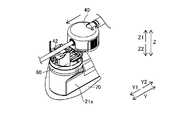
図17に示すように、ロボットアーム21aをドレープ70で覆った状態で、ロボットアーム21aにアダプタ60を取り付ける。アダプタ60は、ロボットアーム21aに対してZ方向に移動させて、ロボットアーム21aに取り付けられる。図18および図19に示すように、ロボットアーム21aに取り付けられたアダプタ60に対して手術器具40を取り付ける。手術器具40は、アダプタ60の先行ガイド部69、先行ガイドレール64および第1のガイドレール63aおよび第2のガイドレール63bに沿ってY方向に移動させて、アダプタ60に取り付けられる。これにより、図20に示すように、手術器具40がアダプタ60を介してロボットアーム21aに取り付けられる。 As shown in FIG. 17, theadapter 60 is attached to therobot arm 21a with therobot arm 21a covered with thedrape 70. Theadapter 60 is moved in the Z direction with respect to therobot arm 21a and attached to therobot arm 21a. As shown in FIGS. 18 and 19, thesurgical instrument 40 is attached to theadapter 60 attached to therobot arm 21a. Thesurgical instrument 40 is attached to theadapter 60 by being moved in the Y direction along the leadingguide portion 69, the leadingguide rail 64 and thefirst guide rail 63a and thesecond guide rail 63b of theadapter 60. As a result, as shown in FIG. 20, thesurgical instrument 40 is attached to therobot arm 21a via theadapter 60.

手術器具40をロボットアーム21aから取り外す場合は、手術器具40の可動部材46のボタン461を押しながら、手術器具40をY2方向にスライド移動させることにより、手術器具40がアダプタ60から外される。 When thesurgical instrument 40 is removed from therobot arm 21a, thesurgical instrument 40 is removed from theadapter 60 by sliding thesurgical instrument 40 in the Y2 direction while pressing thebutton 461 of themovable member 46 of thesurgical instrument 40.

(アダプタへの手術器具の取り付け)
図21〜図26を参照して、先行ガイド部69の案内によるアダプタ60への手術器具40の取り付けについて説明する。
(Attachment of surgical instruments to the adapter)
The attachment of thesurgical instrument 40 to theadapter 60 by the guidance of theleading guide portion 69 will be described with reference to FIGS. 21 to 26.

図21および図24に示すように、手術器具40の突出部49を、アダプタ60の先行ガイド部69に当接するように、手術器具40をアダプタ60のZ1方向側に位置させる。 As shown in FIGS. 21 and 24, thesurgical instrument 40 is positioned on the Z1 direction side of theadapter 60 so that the protrudingportion 49 of thesurgical instrument 40 comes into contact with the leadingguide portion 69 of theadapter 60.

図22および図25に示すように、先行ガイド部69により突出部49を案内させながら、手術器具40をY1方向に移動させる。この際、先行ガイドレール64により手術器具40が案内され、続いて、第1のガイドレール63aおよび第2のガイドレール63bにより手術器具40が案内される。 As shown in FIGS. 22 and 25, thesurgical instrument 40 is moved in the Y1 direction while the leadingguide portion 69 guides the protrudingportion 49. At this time, thesurgical instrument 40 is guided by the leadingguide rail 64, and then thesurgical instrument 40 is guided by thefirst guide rail 63a and thesecond guide rail 63b.

図23および図26に示すように、手術器具40がアダプタ60に装着されると、手術器具40の突出部49がアダプタ60の取付係合部611に係合される。 As shown in FIGS. 23 and 26, when thesurgical instrument 40 is attached to theadapter 60, the protrudingportion 49 of thesurgical instrument 40 is engaged with theattachment engaging portion 611 of theadapter 60.

なお、第2実施形態のその他の構成は、上記第1実施形態と同様である。 The other configurations of the second embodiment are the same as those of the first embodiment.

(変形例)
なお、今回開示された実施形態は、すべての点で例示であって制限的なものではないと考えられるべきである。本発明の範囲は、上記した実施形態の説明ではなく特許請求の範囲によって示され、さらに特許請求の範囲と均等の意味および範囲内でのすべての変更(変形例)が含まれる。
(Modification example)
It should be noted that the embodiments disclosed this time are exemplary in all respects and are not considered to be restrictive. The scope of the present invention is shown by the scope of claims rather than the description of the above-described embodiment, and further includes all modifications (modifications) within the meaning and scope equivalent to the scope of claims.

たとえば、上記第1および第2実施形態では、アダプタの第2面に沿って手術器具をシャフトの延びる方向にスライド移動させることにより、着脱する構成の例を示したが、本発明はこれに限られない。本発明では、アダプタの第2面に沿って手術器具をシャフトの延びる方向と交差する方向にスライド移動させることにより、着脱させてもよい。 For example, in the first and second embodiments described above, an example of a configuration in which a surgical instrument is slid and moved in a direction in which a shaft extends along a second surface of an adapter is shown, but the present invention is limited to this. I can't. In the present invention, the surgical instrument may be attached and detached by sliding the surgical instrument along the second surface of the adapter in a direction intersecting the extending direction of the shaft.

また、上記第1実施形態では、平面視においてアダプタが略円形状を有する構成の例を示したが、本発明はこれに限られない。本発明では、アダプタの平面視における形状は略円形状でなくてもよい。たとえば、アダプタは、平面視において矩形形状を有していてもよい。 Further, in the first embodiment, an example of a configuration in which the adapter has a substantially circular shape in a plan view is shown, but the present invention is not limited to this. In the present invention, the shape of the adapter in a plan view does not have to be substantially circular. For example, the adapter may have a rectangular shape in plan view.

また、上記第1および第2実施形態では、アダプタに4つの駆動伝達部材が設けられている構成の例を示したが、本発明はこれに限られない。本発明では、アダプタに4つ以外の複数の駆動伝達部材が設けられていてもよい。 Further, in the first and second embodiments, an example of a configuration in which the adapter is provided with four drive transmission members has been shown, but the present invention is not limited to this. In the present invention, the adapter may be provided with a plurality of drive transmission members other than the four.

また、上記第1および第2実施形態では、アダプタとドレープとが別体に設けられている構成の例を示したが、本発明はこれに限られない。本発明では、アダプタとドレープとが一体的に設けられている構成でもよい。 Further, in the first and second embodiments, the example of the configuration in which the adapter and the drape are separately provided is shown, but the present invention is not limited to this. In the present invention, the adapter and the drape may be integrally provided.

21a:ロボットアーム、40:手術器具、40a:取付面、42:シャフト、44:回転部材、45:案内溝、45a:第1の案内溝、45b:第2の案内溝、47:先行案内溝、48:第2電極アレイ、49:突出部、60:アダプタ、60a:第1面、60b:第2面、61:基体、62:駆動伝達部材、62a:第1駆動伝達部材、62b:第2駆動伝達部材、63:ガイドレール、63a:第1のガイドレール、63b:第2のガイドレール、64:先行ガイドレール、65:第1電極アレイ、69:先行ガイド部、70:ドレープ、100:ロボット手術システム、441:第1突起部、442:第2突起部、443:第3突起部、451:係合溝、462:係合穴、482:突出部、611:取付係合部、621:第1部材、622:第2部材、623:付勢部材、624:係合部、624a:第1係合部、624b:第2係合部、625:第1凹部、626:第2凹部、631:レール部、632:張出部、633:爪部、652:溝、691:接続部 21a: Robot arm, 40: Surgical instrument, 40a: Mounting surface, 42: Shaft, 44: Rotating member, 45: Guide groove, 45a: First guide groove, 45b: Second guide groove, 47: Advance guide groove , 48: Second electrode array, 49: Projection, 60: Adapter, 60a: First surface, 60b: Second surface, 61: Base, 62: Drive transmission member, 62a: First drive transmission member, 62b: First 2 drive transmission member, 63: guide rail, 63a: first guide rail, 63b: second guide rail, 64: leading guide rail, 65: first electrode array, 69: leading guide section, 70: drape, 100 : Robotic surgery system, 441: 1st protrusion, 442: 2nd protrusion, 443: 3rd protrusion, 451: engagement groove, 462: engagement hole, 482: protrusion, 611: mounting engagement part, 621: 1st member, 622: 2nd member, 623: urging member, 624: engaging part, 624a: 1st engaging part, 624b: 2nd engaging part, 625: 1st recess, 626: second Recess, 631: Rail part, 632: Overhang part, 633: Claw part, 652: Groove, 691: Connection part

Claims (19)

Translated fromJapanese
ロボット手術システムのロボットアームに手術器具を取り外し可能に接続するためのアダプタであって、
前記ロボットアームに取り付けるための第1面と、前記手術器具の取付面が装着される第2面と、を含む基体と、
前記基体に回転可能に設けられた複数の駆動伝達部材と、を備え、
前記基体の前記第2面は、前記取付面に設けられた第1および第2の案内溝にそれぞれ対応する第1および第2のガイドレールを有し、
前記第2面の前記第1および第2のガイドレールは、前記取付面の前記第1および第2の案内溝に挿入され、前記手術器具をスライドさせて前記複数の駆動伝達部材の各々と、前記取付面に設けられた複数の回転部材の各々とが対応するように前記手術器具を案内するように構成されており、
前記第1および第2のガイドレールは、それぞれ、前記第1および第2の案内溝に設けられた係合穴に係合する爪部を有している、アダプタ。
An adapter for detachably connecting surgical instruments to the robot arm of a robotic surgery system.
A substrate including a first surface for mounting on the robot arm and a second surface on which the mounting surface of the surgical instrument is mounted.
A plurality of drive transmission members rotatably provided on the substrate are provided.
The second surface of the substrate has first and second guide rails corresponding to the first and second guide grooves provided on the mounting surface, respectively.
The first and second guide rails on the second surface are inserted into the first and second guide grooves on the mounting surface, and the surgical instrument is slid with each of the plurality of drive transmission members. Itis configured to guide the surgical instrument so as to correspond to each of the plurality of rotating members provided on the mounting surface.
An adapter inwhich the first and second guide rails have claws that engage with engagement holes provided in the first and second guide grooves, respectively .
ロボット手術システムのロボットアームに手術器具を取り外し可能に接続するためのアダプタであって、An adapter for detachably connecting surgical instruments to the robot arm of a robotic surgery system.
前記ロボットアームに取り付けるための第1面と、前記手術器具の取付面が装着される第2面と、を含む基体と、A substrate including a first surface for mounting on the robot arm and a second surface on which the mounting surface of the surgical instrument is mounted.
前記基体に回転可能に設けられた複数の駆動伝達部材と、を備え、A plurality of drive transmission members rotatably provided on the substrate are provided.
前記基体の前記第2面は、前記取付面に設けられた第1および第2の案内溝にそれぞれ対応する第1および第2のガイドレールを有し、The second surface of the substrate has first and second guide rails corresponding to the first and second guide grooves provided on the mounting surface, respectively.
前記第2面の前記第1および第2のガイドレールは、前記取付面の前記第1および第2の案内溝に挿入され、前記手術器具をスライドさせて前記複数の駆動伝達部材の各々と、前記取付面に設けられた複数の回転部材の各々とが対応するように前記手術器具を案内するように構成されており、The first and second guide rails on the second surface are inserted into the first and second guide grooves on the mounting surface, and the surgical instrument is slid with each of the plurality of drive transmission members. It is configured to guide the surgical instrument so as to correspond to each of the plurality of rotating members provided on the mounting surface.
前記複数の駆動伝達部材は、それぞれ、前記取付面に設けられた対応する回転部材に係合する係合部を含み、Each of the plurality of drive transmission members includes an engaging portion that engages with a corresponding rotating member provided on the mounting surface.
前記係合部は、前記複数の駆動伝達部材のうちスライド挿入方向上流側に位置する第1駆動伝達部材に設けられた第1係合部と、前記複数の駆動伝達部材のうちスライド挿入方向下流側に位置する第2駆動伝達部材に設けられた第2係合部と、を有し、The engaging portion includes a first engaging portion provided on the first drive transmission member located on the upstream side of the plurality of drive transmission members in the slide insertion direction, and downstream of the plurality of drive transmission members in the slide insertion direction. It has a second engaging portion provided on the second drive transmission member located on the side, and has.
前記第1係合部は、前記手術器具をスライドさせて前記アダプタに取り付ける場合に、前記第2係合部に係合する前記回転部材が係合しない形状を有している、アダプタ。The first engaging portion is an adapter having a shape in which the rotating member that engages with the second engaging portion does not engage when the surgical instrument is slid and attached to the adapter.
ロボット手術システムのロボットアームに手術器具を取り外し可能に接続するためのアダプタであって、An adapter for detachably connecting surgical instruments to the robot arm of a robotic surgery system.
前記ロボットアームに取り付けるための第1面と、前記手術器具の取付面が装着される第2面と、を含む基体と、A substrate including a first surface for mounting on the robot arm and a second surface on which the mounting surface of the surgical instrument is mounted.
前記基体に回転可能に設けられた複数の駆動伝達部材と、を備え、A plurality of drive transmission members rotatably provided on the substrate are provided.
前記基体の前記第2面は、前記取付面に設けられた第1および第2の案内溝にそれぞれ対応する第1および第2のガイドレールを有し、The second surface of the substrate has first and second guide rails corresponding to the first and second guide grooves provided on the mounting surface, respectively.
前記第2面の前記第1および第2のガイドレールは、前記取付面の前記第1および第2の案内溝に挿入され、前記手術器具をスライドさせて前記複数の駆動伝達部材の各々と、前記取付面に設けられた複数の回転部材の各々とが対応するように前記手術器具を案内するように構成されており、The first and second guide rails on the second surface are inserted into the first and second guide grooves on the mounting surface, and the surgical instrument is slid with each of the plurality of drive transmission members. It is configured to guide the surgical instrument so as to correspond to each of the plurality of rotating members provided on the mounting surface.
前記第1および第2のガイドレールの延びる方向と平行な方向に沿って前記基体から突出するように形成され、前記第1および第2のガイドレールよりも先行して前記手術器具を案内する先行ガイド部をさらに備える、アダプタ。It is formed so as to project from the substrate along a direction parallel to the extending direction of the first and second guide rails, and guides the surgical instrument ahead of the first and second guide rails. An adapter with an additional guide section.
前記駆動伝達部材は、第1部材と、付勢部材を介して前記第1部材に対して移動可能に設けられた第2部材と、を含み、
前記第2面の前記第1および第2のガイドレールは、前記第2部材の前記第1部材に対する移動方向と交差する方向に、前記手術器具の前記第1および第2の案内溝を案内するように構成されている、請求項1〜3のいずれか1項に記載のアダプタ。
The drive transmission member includes a first member and a second member movably provided with respect to the first member via an urging member.
The first and second guide rails on the second surface guide the first and second guide grooves of the surgical instrument in a direction intersecting the moving direction of the second member with respect to the first member. The adapter according toany one of claims 1 to3 , which is configured as described above.
前記基体の前記第2面は、前記第1および第2のガイドレールの間に設けられ、前記取付面に設けられた先行案内溝に対応して、前記第1および第2のガイドレールよりも先行して前記手術器具を案内する先行ガイドレールを有している、請求項1〜4のいずれか1項に記載のアダプタ。The second surface of the substrate is provided between the first and second guide rails and corresponds to the leading guide groove provided on the mounting surface, rather than the first and second guide rails. The adapter according toany one of claims 1 to4 , further comprising a leading guide rail for guiding the surgical instrument in advance. 前記先行ガイドレールは、スライド挿入方向上流側が先細り形状に形成されている、請求項に記載のアダプタ。The adapter according to claim5 , wherein the leading guide rail is formed in a tapered shape on the upstream side in the slide insertion direction. 前記第1および第2のガイドレールは、それぞれ、前記第1および第2の案内溝に設けられた係合穴に係合する爪部を有している、請求項2または3に記載のアダプタ。The adapter according to claim2 or 3 , wherein the first and second guide rails have claws that engage with engagement holes provided in the first and second guide grooves, respectively. .. 前記第1および第2のガイドレールは、それぞれ、前記第1および第2の案内溝のそれぞれに入り込むレール部に対して前記爪部の反対側に設けられ、前記第1および第2の案内溝のそれぞれに設けられた係合溝に係合する張出部を有している、請求項1または7に記載のアダプタ。The first and second guide rails are provided on the opposite side of the claw portion with respect to the rail portion entering each of the first and second guide grooves, respectively, and the first and second guide grooves are provided. The adapter according to claim1 or 7 , which has an overhang that engages with an engagement groove provided in each of the above. 前記基体の前記第2面は、第1電極アレイと、前記取付面に設けられ前記第1電極アレイに接続する第2電極アレイに設けられた突出部を受け入れる溝と、を有している、請求項1〜のいずれか1項に記載のアダプタ。The second surface of the substrate has a first electrode array and a groove provided on the mounting surface to receive a protrusion provided on the second electrode array connected to the first electrode array. The adapter according to any one of claims 1 to8 . 前記複数の駆動伝達部材は、それぞれ、前記取付面に設けられた対応する回転部材に係合する係合部を含み、
前記係合部は、前記複数の駆動伝達部材のうちスライド挿入方向上流側に位置する第1駆動伝達部材に設けられた第1係合部と、前記複数の駆動伝達部材のうちスライド挿入方向下流側に位置する第2駆動伝達部材に設けられ、前記第1係合部と異なる形状を有する第2係合部と、を有している、請求項1または3に記載のアダプタ。
Each of the plurality of drive transmission members includes an engaging portion that engages with a corresponding rotating member provided on the mounting surface.
The engaging portion includes a first engaging portion provided on the first drive transmission member located on the upstream side of the plurality of drive transmission members in the slide insertion direction, and downstream of the plurality of drive transmission members in the slide insertion direction. The adapter according to claim1 or 3 , which is provided on a second drive transmission member located on the side and has a second engaging portion having a shape different from that of the first engaging portion.
前記第1係合部は、前記第2係合部に係合する前記回転部材が係合しない形状を有している、請求項10に記載のアダプタ。The adapter according to claim10 , wherein the first engaging portion has a shape in which the rotating member that engages with the second engaging portion does not engage. 前記第1駆動伝達部材の前記第2面側には、前記第1係合部として、第1凹部および第2凹部が独立して形成されており、
前記第2駆動伝達部材の前記第2面側には、前記第2係合部として、前記第1凹部および前記第2凹部がつながった形状の1つの凹部が形成されており、
前記取付面に設けられた複数の前記回転部材のうち前記第1駆動伝達部材に係合する第1回転部材は、前記第1凹部および前記第2凹部に挿入される第1突起部および第2突起部を有しており、
前記取付面に設けられた複数の前記回転部材のうち前記第2駆動伝達部材に係合する第2回転部材は、前記1つの凹部に挿入される前記第1突起部と、前記第2突起部と、前記第1突起部および前記第2突起部の間に配置された第3突起部と、を有している、請求項2、10または11に記載のアダプタ。
A first recess and a second recess are independently formed as the first engaging portion on the second surface side of the first drive transmission member.
On the second surface side of the second drive transmission member, one recess having a shape in which the first recess and the second recess are connected is formed as the second engaging portion.
Of the plurality of rotating members provided on the mounting surface, the first rotating member that engages with the first drive transmission member is a first protrusion and a second that are inserted into the first recess and the second recess. It has a protrusion and
Of the plurality of rotating members provided on the mounting surface, the second rotating member that engages with the second drive transmission member includes the first protrusion inserted into the one recess and the second protrusion. The adapter according to claim2, 10 or 11 , further comprising a first protrusion and a third protrusion arranged between the first protrusions.
スライド挿入方向は、前記手術器具のシャフトが延びる方向と略平行である、請求項1〜12のいずれか1項に記載のアダプタ。The adapter according to any one of claims 1 to12 , wherein the slide insertion direction is substantially parallel to the direction in which the shaft of the surgical instrument extends. 前記ロボットアームとの間にドレープを挟み込むためのドレープアダプタである、請求項1〜13のいずれか1項に記載のアダプタ。The adapter according to any one of claims 1 to13 , which is a drape adapter for sandwiching a drape with the robot arm. 前記第1および第2のガイドレールの延びる方向と平行な方向に沿って前記基体から突出するように形成され、前記第1および第2のガイドレールよりも先行して前記手術器具を案内する先行ガイド部をさらに備える、請求項1または2に記載のアダプタ。It is formed so as to project from the substrate along a direction parallel to the extending direction of the first and second guide rails, and guides the surgical instrument ahead of the first and second guide rails. The adapter according to claim1 or 2 , further comprising a guide portion. 前記先行ガイド部は、前記手術器具の前記取付面から前記第2面側に突出する突出部を前記第1および前記第2のガイドレールの延びる方向にガイドするように構成されている、請求項3または15に記載のアダプタ。The preceding guide portion is configured to guide a protruding portion protruding from the mounting surface of the surgical instrument toward the second surface side in the extending direction of the first and second guide rails. The adapter according to3 or 15 . 前記基体の前記第2面は、前記取付面の前記突出部が係合する取付係合部を有している、請求項16に記載のアダプタ。The adapter according to claim16 , wherein the second surface of the substrate has a mounting engaging portion with which the protruding portion of the mounting surface engages. 前記先行ガイド部は、前記第1面および前記第2面に略平行で、かつ、前記手術器具を案内する方向に直交する方向において所定の間隔を隔てて略平行に一対設けられている、請求項3、15〜17のいずれか1項に記載のアダプタ。A pair of leading guide portions are provided substantially parallel to the first surface and the second surface, and substantially parallel to each other at a predetermined interval in a direction orthogonal to the direction for guiding the surgical instrument. Item5. The adapter according to any one of Items 3,15 to 17 . 一対の前記先行ガイド部のスライド挿入方向上流側の端部を互いに接続する接続部を含む、請求項18に記載のアダプタ。The adapter according to claim18 , wherein the adapter includes a connection portion for connecting the ends of the pair of leading guide portions on the upstream side in the slide insertion direction to each other.
JP2019063447A2018-08-282019-03-28 adapterActiveJP6821735B2 (en)

Priority Applications (3)

Application NumberPriority DateFiling DateTitle
CN201910751267.7ACN110859671B (en)2018-08-282019-08-15Adapter and method for mounting surgical instrument to robot arm via adapter
US16/542,300US11642186B2 (en)2018-08-282019-08-16Adaptor and method of attaching surgical instrument to robot arm through adaptor
EP19193766.3AEP3616642B1 (en)2018-08-282019-08-27Adaptor and method of attaching surgical instrument to robot arm through adaptor

Applications Claiming Priority (2)

Application NumberPriority DateFiling DateTitle
JP20181593322018-08-28

Related Child Applications (1)

Application NumberTitlePriority DateFiling Date
JP2021000769ADivisionJP7035229B2 (en)2018-08-282021-01-06 adapter

Publications (2)

Publication NumberPublication Date
JP2020032162A JP2020032162A (en)2020-03-05
JP6821735B2true JP6821735B2 (en)2021-01-27

Family

ID=69666334

Family Applications (2)

Application NumberTitlePriority DateFiling Date
JP2019063447AActiveJP6821735B2 (en)2018-08-282019-03-28 adapter
JP2021000769AActiveJP7035229B2 (en)2018-08-282021-01-06 adapter

Family Applications After (1)

Application NumberTitlePriority DateFiling Date
JP2021000769AActiveJP7035229B2 (en)2018-08-282021-01-06 adapter

Country Status (1)

CountryLink
JP (2)JP6821735B2 (en)

Cited By (1)

* Cited by examiner, † Cited by third party
Publication numberPriority datePublication dateAssigneeTitle
EP3888523A1 (en)*2020-03-302021-10-06Medicaroid CorporationEndoscope adaptor, robotic surgical system, method of adjusting rotational position using endoscope adaptor

Families Citing this family (5)

* Cited by examiner, † Cited by third party
Publication numberPriority datePublication dateAssigneeTitle
CN114098845B (en)*2020-08-282023-07-25中国科学院沈阳自动化研究所 A modular surgical robot driving device
CN114305691B (en)*2020-09-282025-09-16北京术锐机器人股份有限公司Sterile drape system of surgical robot and covering method
CN114271941B (en)*2020-09-282025-07-11北京术锐机器人股份有限公司 A surgical robot system
JP2024508759A (en)*2021-02-172024-02-28オーリス ヘルス インコーポレイテッド Medical instrument drive assembly and docking system
CN118662235B (en)*2023-03-172025-09-16北京术锐机器人股份有限公司Connecting adapter capable of transmitting linear motion, connecting assembly and surgical robot system

Family Cites Families (8)

* Cited by examiner, † Cited by third party
Publication numberPriority datePublication dateAssigneeTitle
JPH09272091A (en)*1996-04-091997-10-21Olympus Optical Co LtdRobot hand automatic changer
JP5043414B2 (en)*2005-12-202012-10-10インテュイティブ サージカル インコーポレイテッド Aseptic surgical adapter
CN104706426A (en)*2009-09-232015-06-17伊顿株式会社Sterile adapter, connection structure of wheel and connection structure of surgical instrument
US9408606B2 (en)2012-06-282016-08-09Ethicon Endo-Surgery, LlcRobotically powered surgical device with manually-actuatable reversing system
CN108784838B (en)*2013-08-152021-06-08直观外科手术操作公司Instrument sterile adapter drive interface
US10595836B2 (en)2014-03-172020-03-24Intuitive Surgical Operations, Inc.Systems and methods for confirming disc engagement
CN113729964B (en)*2015-04-272024-08-02直观外科手术操作公司Surgical instrument housing and related systems and methods
BR112019010623B1 (en)2016-12-202023-01-24Verb Surgical Inc SYSTEM FOR USE IN A ROBOTIC SURGICAL SYSTEM AND METHOD OF OPERATING A ROBOTIC SURGICAL SYSTEM

Cited By (2)

* Cited by examiner, † Cited by third party
Publication numberPriority datePublication dateAssigneeTitle
EP3888523A1 (en)*2020-03-302021-10-06Medicaroid CorporationEndoscope adaptor, robotic surgical system, method of adjusting rotational position using endoscope adaptor
US11944268B2 (en)2020-03-302024-04-02Medicaroid CorporationEndoscope adaptor, robotic surgical system, method of adjusting rotational position using endoscope adaptor

Also Published As

Publication numberPublication date
JP2021053470A (en)2021-04-08
JP7035229B2 (en)2022-03-14
JP2020032162A (en)2020-03-05

Similar Documents

PublicationPublication DateTitle
JP6772226B2 (en) Surgical instruments
JP6821735B2 (en) adapter
US11642186B2 (en)Adaptor and method of attaching surgical instrument to robot arm through adaptor
US11234777B2 (en)Adaptor and robotic surgical system
JP6971284B2 (en) Adapter set and adapter
JP6745306B2 (en) Adapter and connection method
JP6823022B2 (en) Drive interface
US12082891B2 (en)Robotic surgical apparatus, surgical instrument, and method of attaching surgical instrument to robot arm
US11642187B2 (en)Surgical instrument, assembly including adaptor and surgical instrument, and robotic surgical system
US11266386B2 (en)Adapter, robotic surgical system, and adapter attaching method
JP6839220B2 (en) How to detect the attachment of surgical instruments to the drive interface, adapter, and drive interface
US20220117691A1 (en)Adaptor, method of detaching adaptor from robot arm, and robotic surgical system
EP3811883A1 (en)Surgical instrument

Legal Events

DateCodeTitleDescription
A521Request for written amendment filed

Free format text:JAPANESE INTERMEDIATE CODE: A523

Effective date:20190809

A621Written request for application examination

Free format text:JAPANESE INTERMEDIATE CODE: A621

Effective date:20190809

A977Report on retrieval

Free format text:JAPANESE INTERMEDIATE CODE: A971007

Effective date:20200722

A131Notification of reasons for refusal

Free format text:JAPANESE INTERMEDIATE CODE: A131

Effective date:20200818

A521Request for written amendment filed

Free format text:JAPANESE INTERMEDIATE CODE: A523

Effective date:20201009

TRDDDecision of grant or rejection written
A01Written decision to grant a patent or to grant a registration (utility model)

Free format text:JAPANESE INTERMEDIATE CODE: A01

Effective date:20201208

A61First payment of annual fees (during grant procedure)

Free format text:JAPANESE INTERMEDIATE CODE: A61

Effective date:20210106

R150Certificate of patent or registration of utility model

Ref document number:6821735

Country of ref document:JP

Free format text:JAPANESE INTERMEDIATE CODE: R150

R250Receipt of annual fees

Free format text:JAPANESE INTERMEDIATE CODE: R250

R250Receipt of annual fees

Free format text:JAPANESE INTERMEDIATE CODE: R250


[8]ページ先頭

©2009-2025 Movatter.jp