Movatterモバイル変換


[0]ホーム

URL:


JP6820258B2 - Tissue retrieval system and method - Google Patents

Tissue retrieval system and method
Download PDF

Info

Publication number
JP6820258B2
JP6820258B2JP2017525798AJP2017525798AJP6820258B2JP 6820258 B2JP6820258 B2JP 6820258B2JP 2017525798 AJP2017525798 AJP 2017525798AJP 2017525798 AJP2017525798 AJP 2017525798AJP 6820258 B2JP6820258 B2JP 6820258B2
Authority
JP
Japan
Prior art keywords
bag
shield
tissue
ring
guard
Prior art date
Legal status (The legal status is an assumption and is not a legal conclusion. Google has not performed a legal analysis and makes no representation as to the accuracy of the status listed.)
Active
Application number
JP2017525798A
Other languages
Japanese (ja)
Other versions
JP2017534395A5 (en
JP2017534395A (en
Inventor
セレヌ ワチリ
セレヌ ワチリ
トレイシー ブレスリン
トレイシー ブレスリン
スティーヴン シー ケスラー
スティーヴン シー ケスラー
ニコライ ポールセン
ニコライ ポールセン
ネイサン コリンズ
ネイサン コリンズ
アレクサンドラ ドゥ
アレクサンドラ ドゥ
エドゥアルド ボラーニョス
エドゥアルド ボラーニョス
ブーン プラヴォン
ブーン プラヴォン
パトリック エリオット
パトリック エリオット
マシュー エイ ウィクシー
マシュー エイ ウィクシー
ウェイン ヤング
ウェイン ヤング
ジェイコブ フィレク
ジェイコブ フィレク
ケヴィン ビー カステロ
ケヴィン ビー カステロ
アダム ホーク
アダム ホーク
グレッグ ホフステッタ
グレッグ ホフステッタ
ジャクリーン デマルキ
ジャクリーン デマルキ
エイミー ガルセス
エイミー ガルセス
ハイディ ホームズ
ハイディ ホームズ
アレクサンダー シーン
アレクサンダー シーン
Original Assignee
アプライド メディカル リソーシーズ コーポレイション
Priority date (The priority date is an assumption and is not a legal conclusion. Google has not performed a legal analysis and makes no representation as to the accuracy of the date listed.)
Filing date
Publication date
Application filed by アプライド メディカル リソーシーズ コーポレイション, アプライド メディカル リソーシーズ コーポレイションfiledCriticalアプライド メディカル リソーシーズ コーポレイション
Publication of JP2017534395ApublicationCriticalpatent/JP2017534395A/en
Publication of JP2017534395A5publicationCriticalpatent/JP2017534395A5/ja
Priority to JP2021000260ApriorityCriticalpatent/JP7520733B2/en
Application grantedgrantedCritical
Publication of JP6820258B2publicationCriticalpatent/JP6820258B2/en
Activelegal-statusCriticalCurrent
Anticipated expirationlegal-statusCritical

Links

Images

Classifications

Landscapes

Description

Translated fromJapanese

本発明は、医療器具、特に体開口部からの組織の取り出しまたは除去のためのシステムおよび方法に関する。 The present invention relates to medical devices, in particular systems and methods for removing or removing tissue from body openings.

〔関連出願の説明〕
本願は、2014年11月13日に出願された米国特許仮出願第62/079,171号(発明の名称:Systems and methods for tissue removal)、2014年11月18日に出願された米国特許仮出願第62/081,297号(発明の名称:Systems and methods for tissue removal)、および2015年1月23日に出願された米国特許仮出願第62/107,107号(発明の名称:Cut-resistant retracting tissue bag)の優先権および権益主張出願である。
[Explanation of related applications]
This application is a US patent provisional application No. 62 / 079,171 (title of the invention: Systems and methods for tissue removal) filed on November 13, 2014, and a US patent provisional application filed on November 18, 2014. Application No. 62 / 081,297 (Title of Invention: Systems and methods for tissue removal) and US Patent Provisional Application No. 62 / 107,107 (Title of Invention: Cut-) filed on January 23, 2015. It is a priority and interest claim application for resistant retracting tissue bag).

小さな切開創部位および/または種々の体口を含む体開口部からの組織の外科的取り出しのためのシステムおよび方法が文献記載されている。必要な場合、体腔内に位置する外科的に標的となる組織に接近するために小さな切開創が患者に作られる。外科的に標的となる組織には、初期切開創を作らないで体口を通って接近することも可能である。場合によっては、切開創または体口から標的組織にじかに接近する。場合によっては、接近器具システムが切開創および/または体口中に、これらを横切って、これらのところにおよび/またはこれらの中に配置されるとともに位置決めされて、組織をレトラクトし、切開創または体口を拡大し、再付形するとともに/あるいは隔離する。接近またはアクセス器具システムは、体腔または体口内にまたはこれに隣接して位置する標的組織に接近するための門またはポータルとして働く。標的組織は、公知の外科的技術または外科的処置を採用して隣接するとともに周りの組織から剥離される。いったん自由にされると、標的組織は、小さな切開創または体口を通っていつでも取り出し可能な状態にある。標的組織が大きすぎてこれを全体として除去することができない場合、標的組織のサイズを減少させて小さな切開創を通って標的組織を部分的に取り出す。理想的には、外科医は、標的組織を「くりぬき(core)」または「剥ぎ取って(peel)」これをできるだけ一体の状態に保つ。しかしながら、5割以上の確率で標的組織は、多数の小片になってしまう。 Systems and methods for surgical removal of tissue from body openings, including small incision sites and / or various body mouths, have been documented. If necessary, a small incision is made in the patient to access the surgically targeted tissue located within the body cavity. It is also possible to approach the surgically targeted tissue through the body mouth without making an initial incision. In some cases, the target tissue is approached directly through the incision or body mouth. In some cases, a proximity device system is positioned in and / or in the incision and / or body mouth, across them, where and / or in these, retracting tissue, incision or body. Enlarge and reshape and / or isolate the mouth. The access or access device system acts as a gate or portal for access to target tissue located in or adjacent to the body cavity or mouth. The target tissue is adjacent and detached from the surrounding tissue using known surgical techniques or procedures. Once freed, the target tissue is ready for removal through a small incision or body mouth. If the target tissue is too large to remove as a whole, the size of the target tissue is reduced and the target tissue is partially removed through a small incision. Ideally, the surgeon "cores" or "peels" the target tissue to keep it as cohesive as possible. However, with a probability of 50% or more, the target tissue becomes a large number of small pieces.

標的組織の寸法を減少させることは、細切術(morcellation)と呼ばれる。細切手技では、小刀またはナイフを用いて手動でまたは電動式細切器を採用して標的組織を小片の状態に切断し、そして標的組織が小さな切開創を通って取り出し可能であるように標的組織を切断する。標的組織の小片は、小さな切開創を通って患者から取り出される。標的組織をこれが小さな切開創にあった状態で通過するために寸法を減少させているとき、組織の小片が切り落とされて患者の体内に残される場合がある。したがって、細切は、悪性腫瘍または子宮内膜症の場合に禁忌である。癌を細切した場合、かかる細切によって悪性の組織が広がって癌のステージが上がる場合があり、そして患者の死亡率が増加する場合がある。 Reducing the size of the target tissue is called morcellation. In the chopping technique, the target tissue is cut into small pieces, either manually with a sword or knife or by using an electric chopping device, and the target tissue is targeted so that it can be removed through a small incision. Cut the tissue. A small piece of target tissue is removed from the patient through a small incision. When reducing the size to pass through the target tissue as it is in a small incision, small pieces of tissue may be cut off and left in the patient's body. Therefore, shredding is contraindicated in the case of malignant tumors or endometriosis. When the cancer is shredded, the shreds may spread malignant tissue, raise the stage of the cancer, and increase patient mortality.

子宮摘出術は、細切を含む場合のある外科的処置の一例である。米国において婦人に対して500,000件を超える子宮摘出術が毎年行われている。婦人が子宮摘出術を受けるのが良い通常の理由は、フィブロイド、癌、子宮内膜症または子宮脱が存在している場合である。これら子宮摘出術のうち約200,000件は、腹腔鏡下で行われる。子宮が大きすぎる(300gを超える)ので膣を通って取り出すことができない場合または子宮頸が依然として定位置にある場合、腹部切開創を通りまたは膣を通って取り出すためには検体の寸法を減少させなければならない。筋腫切除術(フィブロイド除去)の実施中、細切手技を用いて大きなフィブロイドを摘出する必要がある場合もある。細切中、標的組織(通常、子宮および場合によっては付属器構造体)を例えば組織把持器により腹壁表面に至らせてブレードを用いてその寸法を減少させ、そして切開創を通って骨盤腔から取り出す。別法では、体口、例えば膣を通って標的組織を取り出す。フィブロイドまたは子宮平滑筋腫は、子宮摘出術のうちで約30〜40%の原因となっている。これらは、子宮の良性腫瘍であり、これらフィブロイドまたは子宮平滑筋腫は、重くかつ有痛性の出血を招く場合がある。過去において、これら腫瘍が見逃された癌または平滑筋肉腫である場合があり、10,000人の婦人のうちで約1人が罹患していると考えられていた。より最近のデータの結果は、これら腫瘍のうちで見逃した悪性腫瘍の極めて高いリスクを裏付けており、その範囲は、1:1000〜1;400に見積もられる。リスクがこのように高いので、多くの外科医は、開放細切術と呼ばれるプロセスにおいて袋を用いないで細切を行うのではなく、袋の中で細切を行ってあちこちと漂う小片を収容し、そして腫瘍細胞の拡散および播種(シーディング)を防止することにより検体を包み込んで閉鎖式細切プロセスを実施するように自分の術式を変え始めた。AAGL、ACOG、およびSGOを含む多くのGYN学会は、開放細切術の潜在的な危険性を警告する声明を出した。2014年4月17日付けで、FDAは、フィブロイドのためのこれらの手技を受ける婦人にとって子宮摘出術および筋腫切除術の実施のために開放電動式細切法の利用を控える旨の声明を出した。FDAはまた、悪性の可能性の見積もりを350に対して1の割合に増大させた。これらの理由で、組織検体を安全にかつ効果的に縮小するシステムおよび方法が要望されている。本発明は、閉鎖系で実施される手動細切と電動式細切の両方のためのかかる安全なシステムおよび方法に関する。 A hysterectomy is an example of a surgical procedure that may involve shredding. More than 500,000 hysterectomy procedures are performed annually on women in the United States. The usual reason women are better off undergoing a hysterectomy is in the presence of fibroids, cancer, endometriosis or uterine prolapse. About 200,000 of these hysterectomy procedures are performed laparoscopically. If the uterus is too large (more than 300 g) to be removed through the vagina or if the cervix is still in place, reduce the size of the specimen to remove it through the abdominal incision or through the vagina There must be. During fibroidectomy (fibroid removal), it may be necessary to remove large fibroids using postage stamps. During shredding, the target tissue (usually the uterus and possibly appendage structures) is reached to the abdominal wall surface, for example with a tissue grasper, reduced in size with a blade, and removed from the pelvic cavity through an incision. .. Alternatively, the target tissue is removed through the body mouth, such as the vagina. Fibroids or uterine leiomyomas are responsible for about 30-40% of hysterectomy procedures. These are benign tumors of the uterus, and these fibroids or uterine leiomyomas can lead to severe and painful bleeding. In the past, these tumors could be missed cancers or leiomyosarcoma, and it was thought that about 1 in 10,000 women was affected. The results of more recent data support the extremely high risk of missed malignancies among these tumors, the range of which is estimated to be 1: 1000-1; 400. Because of this high risk, many surgeons do not use a bag to shred in a process called open shredding, but rather shred in a bag to contain small pieces that float around. , And began to change his procedure to wrap the specimen and perform a closed shredding process by preventing the spread and seeding of tumor cells. Many GYN societies, including AAGL, ACOG, and SGO, have issued statements warning of the potential dangers of open pruning. On April 17, 2014, the FDA issued a statement stating that women undergoing these procedures for fibroids would refrain from using open electric shredding to perform hysterectomy and fibroidectomy. did. The FDA has also increased the likelihood of malignancy by a ratio of 1 to 350. For these reasons, there is a need for systems and methods for safely and effectively shrinking tissue specimens. The present invention relates to such safe systems and methods for both manual and electric shredding performed in closed systems.

本発明の一観点によれば、組織辺縁を定める体開口部に通して組織検体を取り出すシステムが提供される。このシステムは、シールドを含む。このシールドは、軟質の耐切断性材料で作られたバンドを有する。バンドは、頂端部および底端部ならびに第1の端部および第2の端部によって互いに連結された内面および外面を有する。バンドは、長手方向軸線を備えた中央ルーメンを画定するよう構成されている。中央ルーメンは、長手方向軸線に垂直なルーメン直径を有する。バンドは、第1の端のところの外面の少なくとも一部分が第2の端のところの内面とオーバーラップするとともにこの内面と並置関係をなして螺旋を形成するとともにオーバーラップ部分を構成する縮小形態にバンドが動くことができるよう分割されている。シールドは、オーバーラップ部分を変化させることによって可変ルーメン直径を有するよう構成されている。シールドは、ルーメン直径を固定するよう構成されたロック機構体を含む。ロック機構体は、内面上に形成された少なくとも1つの内側当接部を含む。内側当接部は、長手方向軸線沿いにバンドの少なくとも一部分に沿って頂端と底端との間に延びている。第1の端は、ロック形態において内径の縮小を阻止するよう内側当接部に接触するよう構成されている。 According to one aspect of the present invention, there is provided a system for extracting a tissue sample through a body opening that defines a tissue margin. This system includes a shield. This shield has a band made of a soft cutting resistant material. The band has an inner and outer surface that are connected to each other by a top and bottom ends and a first end and a second end. The band is configured to define a central lumen with a longitudinal axis. The central lumen has a lumen diameter perpendicular to the longitudinal axis. The band is in a reduced form in which at least a part of the outer surface at the first end overlaps with the inner surface at the second end and forms a spiral in a juxtaposed relationship with the inner surface and constitutes the overlapping portion. It is divided so that the band can move. The shield is configured to have a variable lumen diameter by varying the overlap portion. The shield includes a locking mechanism configured to fix the lumen diameter. The locking mechanism includes at least one inner abutting portion formed on the inner surface. The inner abutment extends between the top and bottom along at least a portion of the band along the longitudinal axis. The first end is configured to contact the inner abutting portion in the locked form so as to prevent the inner diameter from shrinking.

本発明の別の観点によれば、組織辺縁を定める体開口部に通して組織検体を取り出すシステムが提供される。このシステムは、シールドを含む。このシールドは、軟質の耐切断性材料で作られたバンドを有する。バンドは、頂端部および底端部ならびに第1の端部および第2の端部によって互いに連結された内面および外面を有する。バンドは、長手方向軸線を備えた中央ルーメンを画定するよう構成されている。中央ルーメンは、長手方向軸線に垂直なルーメン直径を有する。バンドは、第1の端のところの外面の少なくとも一部分が第2の端のところの内面とオーバーラップするとともにこの内面と並置関係をなして螺旋を形成するとともにオーバーラップ部分を構成する縮小形態にバンドが動くことができるよう分割されている。シールドは、オーバーラップ部分を変化させることによって可変ルーメン直径を有するよう構成されている。シールドは、ルーメン直径を固定するよう構成されたロック機構体を含む。ロック機構体は、内面上に形成された少なくとも1つの内側当接部および外面上に形成された少なくとも1つの外側当接部を含む。内側当接部および外側当接部は、長手方向軸線沿いにバンドの少なくとも一部分に沿って頂端と底端との間に延びている。少なくとも1つの内側当接部は、ロック形態において内径の縮小を阻止するよう少なくとも1つの外側当接部に接触するよう構成されている。 According to another aspect of the present invention, there is provided a system for extracting a tissue sample through a body opening that defines a tissue margin. This system includes a shield. This shield has a band made of a soft cutting resistant material. The band has an inner and outer surface that are connected to each other by a top and bottom ends and a first end and a second end. The band is configured to define a central lumen with a longitudinal axis. The central lumen has a lumen diameter perpendicular to the longitudinal axis. The band is in a reduced form in which at least a part of the outer surface at the first end overlaps with the inner surface at the second end and forms a spiral in a juxtaposed relationship with the inner surface and constitutes the overlapping portion. It is divided so that the band can move. The shield is configured to have a variable lumen diameter by varying the overlap portion. The shield includes a locking mechanism configured to fix the lumen diameter. The locking mechanism includes at least one inner abutting portion formed on the inner surface and at least one outer abutting portion formed on the outer surface. The inner and outer abutments extend between the top and bottom edges along at least a portion of the band along the longitudinal axis. The at least one inner abutment is configured to contact the at least one outer abutment in the locked form so as to prevent the inner diameter from shrinking.

本発明の別の観点によれば、組織辺縁を定める体開口部に通して組織検体を取り出すシステムが提供される。このシステムは、シールドを含む。このシールドは、軟質の耐切断性材料で作られたバンドを有する。バンドは、頂端部および底端部ならびに第1の端部および第2の端部によって互いに連結された内面および外面を有する。バンドは、長手方向軸線を備えた中央ルーメンを画定するよう構成されている。中央ルーメンは、長手方向軸線に垂直なルーメン直径を有する。バンドは、第1の端のところの外面の少なくとも一部分が第2の端のところの内面とオーバーラップするとともにこの内面と並置関係をなして螺旋を形成するとともにオーバーラップ部分を構成する縮小形態にバンドが動くことができるよう分割されている。シールドは、オーバーラップ部分を変化させることによって可変ルーメン直径を有するよう構成されている。シールドは、ルーメン直径を固定するよう構成されたロック機構体を含む。ロック機構体は、内面内に形成された少なくとも1つの内側当接部を含む。少なくとも1つの内側当接部は、ロック状態のルーメン直径を有するロック形態を定めるよう第1の端または外面内に形成された少なくとも1つの外側当接部のうちの一方に接触するよう構成されている。 According to another aspect of the present invention, there is provided a system for extracting a tissue sample through a body opening that defines a tissue margin. This system includes a shield. This shield has a band made of a soft cutting resistant material. The band has an inner and outer surface that are connected to each other by a top and bottom ends and a first end and a second end. The band is configured to define a central lumen with a longitudinal axis. The central lumen has a lumen diameter perpendicular to the longitudinal axis. The band is in a reduced form in which at least a part of the outer surface at the first end overlaps with the inner surface at the second end and forms a spiral in a juxtaposed relationship with the inner surface and constitutes the overlapping portion. It is divided so that the band can move. The shield is configured to have a variable lumen diameter by varying the overlap portion. The shield includes a locking mechanism configured to fix the lumen diameter. The locking mechanism includes at least one inner abutting portion formed within the inner surface. The at least one inner abutment is configured to contact one of at least one outer abutment formed within the first end or outer surface to define a locking form having a locked lumen diameter. There is.

体壁に設けた開口部内に配置された本発明による収容袋およびガードの断面図である。It is sectional drawing of the storage bag and guard by this invention arranged in the opening provided in the body wall.本発明によるガードの上から見た斜視図である。It is a perspective view seen from the top of the guard by this invention.本発明によるガードの側面図である。It is a side view of the guard by this invention.本発明によるガードの端面図である。It is an end view of the guard by this invention.本発明によるガードの図4の5‐5線矢視断面図である。It is a cross-sectional view taken along the line 5-5 of FIG. 4 of the guard according to the present invention.本発明によるガードの図4の6‐6線矢視断面図である。FIG. 6 is a cross-sectional view taken along the line 6-6 of FIG. 4 of the guard according to the present invention.本発明によるガードの上から見た斜視図である。It is a perspective view seen from the top of the guard by this invention.本発明によるガードの側面図である。It is a side view of the guard by this invention.本発明によるガードの端面図である。It is an end view of the guard by this invention.本発明によるガードの図9の10‐10線矢視断面図である。FIG. 9 is a cross-sectional view taken along the line 10-10 of FIG. 9 of the guard according to the present invention.本発明によるキャップの上から見た斜視図である。It is a perspective view seen from the top of the cap by this invention.本発明によるキャップおよびガードの断面側面図である。It is sectional drawing side view of the cap and guard by this invention.本発明によるキャップおよびガードの側面図である。It is a side view of a cap and a guard by this invention.本発明によるキャップおよびガードの上から見た斜視図である。It is a perspective view seen from the top of the cap and guard by this invention.本発明によるガードの上から見た斜視図である。It is a perspective view seen from the top of the guard by this invention.本発明によるガードの上から見た斜視図である。It is a perspective view seen from the top of the guard by this invention.本発明によるガードの断面側面図である。It is sectional drawing side view of the guard by this invention.本発明によるレトラクタの上から見た斜視図である。It is a perspective view seen from the top of the retractor by this invention.本発明によるレトラクタの上から見た斜視図である。It is a perspective view seen from the top of the retractor by this invention.本発明による収容袋とレトラクタの組み合わせの上から見た斜視図である。It is a perspective view seen from the top of the combination of the storage bag and the retractor by this invention.本発明による組織検体、体壁および2つのリングを備えた収容袋の断面側面図である。FIG. 5 is a cross-sectional side view of a storage bag provided with a tissue sample, a body wall and two rings according to the present invention.本発明による拡張された状態の収容袋の上から見た斜視図である。It is a perspective view seen from the top of the storage bag in the expanded state by this invention.本発明による部分的に潰された状態の収容袋の上から見た斜視図である。It is a perspective view seen from the top of the storage bag in a partially crushed state by this invention.本発明によるねじられた状態の収容袋の上から見た斜視図である。It is a perspective view seen from the top of the storage bag in a twisted state by this invention.本発明によるねじられた状態の収容袋の平面図である。It is a top view of the storage bag in a twisted state by this invention.本発明による非組み立て状態の2部品構成型ガードの上から見た斜視図である。It is a perspective view seen from the top of the two-part composition type guard in the non-assembled state by this invention.本発明による組み立て状態の2部品構成型ガードの上から見た斜視図である。It is a perspective view seen from the top of the two-part composition type guard in the assembled state by this invention.本発明によるガードの上から見た斜視図である。It is a perspective view seen from the top of the guard by this invention.本発明によるレトラクタリングおよびガードの上から見た斜視図である。It is a perspective view seen from the top of the retractor ring and guard by this invention.本発明によるガードの上から見た斜視図である。It is a perspective view seen from the top of the guard by this invention.本発明によるレトラクタリングおよびガードの部分断面図である。FIG. 3 is a partial cross-sectional view of a retractor ring and a guard according to the present invention.本発明による取り外し可能なシールハウジングを備えたバルーントロカールの上から見た斜視図である。It is a top view of the balloon trocar provided with the removable seal housing according to the present invention.本発明によるバルーントロカールの断面側面図である。It is sectional drawing side view of the balloon trocar by this invention.本発明による安定器の側面図である。It is a side view of the ballast by this invention.本発明による安定器の底面図である。It is a bottom view of the ballast by this invention.本発明による安定器の図33の34‐34線矢視断面図である。FIG. 33 is a cross-sectional view taken along the line 34-34 of the ballast according to the present invention.本発明による細切器安定器の側面図である。It is a side view of the shredder ballast by this invention.本発明に従って細切器安定器をロック形態で示す断面平面図である。FIG. 5 is a cross-sectional plan view showing a shredder ballast in a locked form according to the present invention.本発明による安定器を非ロック形態で示す平面図である。It is a top view which shows the ballast by this invention in the unlocked form.本発明に従って細切器安定器をロック解除形態で示す断面平面図である。It is sectional drawing which shows the shredder ballast in the unlocked form according to this invention.本発明に従って体開口部内に配置された収容袋の上からみた斜視図である。It is a perspective view seen from the top of the storage bag arranged in the body opening according to the present invention.本発明に従って体開口部内に配置された収容袋および収容袋に連結された非ロック形態の細切器安定器の上から見た斜視図である。It is a perspective view seen from the top of the storage bag arranged in the body opening according to the present invention, and the non-locking type shredder ballast connected to the storage bag.本発明に従って安定キャップに連結された保護栓塞子を有する細切器の上から見た斜視図である。It is a perspective view seen from the top of the shredder having a protective embolus connected to a stabilizing cap according to the present invention.本発明に従って安定キャップに連結された保護栓塞子を有する細切器の下から見た斜視図である。It is a perspective view seen from the bottom of the shredder having a protective embolus connected to a stabilizing cap according to the present invention.本発明に従って安定キャップに連結された細切器の上から見た斜視図である。It is a perspective view seen from the top of the shredder connected to the stability cap according to the present invention.本発明による安定キャップの上から見た斜視図である。It is a perspective view seen from the top of the stability cap by this invention.本発明による収容袋の上から見た斜視図である。It is a perspective view seen from the top of the storage bag by this invention.本発明に従って体壁を横切って配置された収容袋内の組織検体の断面側面図である。It is sectional drawing side view of the tissue sample in the storage bag arranged across the body wall according to this invention.本発明による収容袋展開器械の側面図である。It is a side view of the storage bag deploying machine according to this invention.本発明による収容袋および展開キャップの側面図である。It is a side view of the storage bag and the development cap according to this invention.本発明による収容袋の上からみた斜視図である。It is a perspective view seen from the top of the storage bag by this invention.本発明に従って体壁を横切って配置された収容袋内の組織検体の断面側面図である。It is sectional drawing side view of the tissue sample in the storage bag arranged across the body wall according to this invention.本発明による収容袋の上からみた斜視図である。It is a perspective view seen from the top of the storage bag by this invention.本発明による収容袋の上からみた斜視図である。It is a perspective view seen from the top of the storage bag by this invention.本発明による収容袋の平面図である。It is a top view of the storage bag according to this invention.本発明による収容袋の上から見た斜視図である。It is a perspective view seen from the top of the storage bag by this invention.本発明による収容袋の上からみた斜視図である。It is a perspective view seen from the top of the storage bag by this invention.本発明による収容袋のためのパターンの平面図であり、実線が谷形折り目を示し、破線が山形折り目を示す図である。It is a plan view of the pattern for the storage bag by this invention, the solid line shows the valley crease, and the broken line shows the chevron fold.本発明による収容袋のための寸法を備えたパターンの部分平面図である。FIG. 3 is a partial plan view of a pattern with dimensions for a storage bag according to the present invention.本発明に従って上から見て実質的に正方形である収容袋のためのパターンの平面図である。FIG. 5 is a plan view of a pattern for a storage bag that is substantially square when viewed from above according to the present invention.本発明に従って三角形の開口端部を備えた収容袋の平面図である。It is a top view of the storage bag provided with a triangular opening end according to the present invention.本発明によるガードの上から見た斜視図である。It is a perspective view seen from the top of the guard by this invention.本発明によるモールド内のガードの上から見た斜視図である。It is a perspective view seen from the top of the guard in the mold by this invention.本発明によるモールド上のガードの上から見た斜視図である。It is a perspective view seen from the top of the guard on the mold by this invention.本発明による収容袋の上から見た斜視図である。It is a perspective view seen from the top of the storage bag by this invention.本発明による収容袋のリングの側面図である。It is a side view of the ring of the storage bag according to this invention.本発明による収容袋のリングの図55Aの55B‐55B線矢視断面図である。It is a cross-sectional view taken along theline 55B-55B of FIG. 55A of the ring of the storage bag according to the present invention.本発明による収容袋のためのリング内に形成される前における半剛性ロッドの上から見た斜視図である。It is a perspective view seen from the top of the semi-rigid rod before being formed in the ring for the storage bag by this invention.本発明による収容袋のリングの上から見た斜視図である。It is a perspective view seen from the top of the ring of the storage bag by this invention.本発明による収容袋側壁の平面図である。It is a top view of the side wall of the storage bag according to this invention.本発明による収容袋側壁の側面図である。It is a side view of the side wall of the storage bag according to this invention.本発明による収容袋の側面図である。It is a side view of the storage bag according to this invention.本発明による収容袋の58Aの58B線矢視断面図である。FIG. 5 is a cross-sectional view taken along theline 58B of 58A of the storage bag according to the present invention.本発明による収容袋の側面図である。It is a side view of the storage bag according to this invention.本発明による収容袋の上からみた斜視図である。It is a perspective view seen from the top of the storage bag by this invention.本発明による袋導入器の上から見た斜視図である。It is a perspective view seen from the top of the bag introducer by this invention.本発明による袋導入器の上から見た斜視図である。It is a perspective view seen from the top of the bag introducer by this invention.本発明による収容袋および袋導入器の上から見た斜視図である。It is a perspective view seen from the top of the storage bag and the bag introducer according to this invention.本発明による収容袋および袋導入器の上から見た斜視図である。It is a perspective view seen from the top of the storage bag and the bag introducer according to this invention.本発明によるガードの上から見た斜視図である。It is a perspective view seen from the top of the guard by this invention.本発明に従って体壁を横切って配置された収容袋およびガード内の組織検体の断面側面図である。FIG. 5 is a cross-sectional side view of a tissue sample in a storage bag and a guard arranged across a body wall according to the present invention.本発明によるガードの上から見た斜視図である。It is a perspective view seen from the top of the guard by this invention.本発明によるガードの2つの側壁コンポーネントの側面図である。It is a side view of the two side wall components of the guard according to the present invention.本発明によるガードの上から見た斜視図である。It is a perspective view seen from the top of the guard by this invention.本発明によるガードの側面図である。It is a side view of the guard by this invention.本発明による体開口部内のガードの側面図である。It is a side view of the guard in the body opening by this invention.本発明によるガードの上から見た斜視図である。It is a perspective view seen from the top of the guard by this invention.本発明によるガードの上から見た斜視図である。It is a perspective view seen from the top of the guard by this invention.本発明によるガードの上から見た斜視図である。It is a perspective view seen from the top of the guard by this invention.本発明によるガードの部分透視側面図である。It is a partial perspective side view of the guard by this invention.本発明によるガードの部分透視側面図である。It is a partial perspective side view of the guard by this invention.本発明によるガードの側壁の断面図である。It is sectional drawing of the side wall of the guard by this invention.本発明によるガードの上から見た斜視図である。It is a perspective view seen from the top of the guard by this invention.本発明によるガードの側面図である。It is a side view of the guard by this invention.本発明によるガードの半透明底面図である。It is a translucent bottom view of the guard by this invention.本発明によるガードの半透明平面図である。It is a semi-transparent plan view of the guard by this invention.本発明によるガードの図78Bの78C‐78C線矢視断面図である。It is a cross-sectional view taken along theline 78C-78C of FIG. 78B of the guard according to the present invention.本発明によるガードの上から見た部分透視斜視図である。It is a partial perspective perspective view seen from the top of the guard by this invention.本発明によるガードの平面図である。It is a top view of the guard by this invention.本発明によるガードの平面図である。It is a top view of the guard by this invention.本発明によるガードの上から見た斜視図である。It is a perspective view seen from the top of the guard by this invention.本発明によるガードの上から見た斜視図である。It is a perspective view seen from the top of the guard by this invention.本発明によるガードの断面平面図である。It is sectional drawing of the guard by this invention.本発明によるガードの上から見た斜視図である。It is a perspective view seen from the top of the guard by this invention.本発明によるガードの上から見た斜視図である。It is a perspective view seen from the top of the guard by this invention.本発明による細切器およびガードの側面図である。It is a side view of the shredder and guard by this invention.本発明による細切器およびガードの断面側面図である。It is sectional drawing side view of the shredder and guard by this invention.本発明による細切器の下から見た斜視図である。It is a perspective view seen from the bottom of the shredder according to this invention.本発明によるエネルギー式細切器および把持器の上から見た斜視図である。It is a perspective view seen from the top of the energy type shredding device and the gripping device according to the present invention.本発明によるガードの上から見た斜視図である。It is a perspective view seen from the top of the guard by this invention.本発明によるガードの上から見た部分透視斜視図である。It is a partial perspective perspective view seen from the top of the guard by this invention.本発明によるガードの側面図である。It is a side view of the guard by this invention.本発明によるガードの部分透視側面図である。It is a partial perspective side view of the guard by this invention.本発明によるガードの側面図である。It is a side view of the guard by this invention.本発明によるガードの部分透視平面図である。It is a partial perspective plan view of the guard by this invention.本発明によるガードの断面平面図である。It is sectional drawing of the guard by this invention.本発明によるガードの部分透視断面平面図である。It is a partial perspective sectional plan view of the guard by this invention.本発明によるレトラクタおよびガードの部分透視側面図である。It is a partial perspective side view of the retractor and the guard by this invention.本発明によるレトラクタおよびガードの断面側面図である。It is sectional drawing side view of the retractor and guard by this invention.本発明によるレトラクタおよびガードの上から見た断面斜視図である。It is sectional drawing seen from the top of the retractor and guard by this invention.本発明によるレトラクタおよびガードの上から見た断面斜視図である。It is sectional drawing seen from the top of the retractor and guard by this invention.本発明によるレトラクタおよびガードの上から見た部分透視斜視図である。It is a partial perspective perspective view seen from the top of the retractor and the guard by this invention.本発明によるガードの側面図である。It is a side view of the guard by this invention.本発明によるガードの平面図である。It is a top view of the guard by this invention.本発明によるレトラクタおよびガードの上から見た斜視図である。It is a perspective view seen from the top of the retractor and the guard by this invention.本発明によるレトラクタおよびガードの平面図である。It is a top view of the retractor and the guard by this invention.本発明によるガードの下から見た斜視図である。It is a perspective view seen from the bottom of the guard by this invention.本発明によるガードの上から見た斜視図である。It is a perspective view seen from the top of the guard by this invention.本発明によるガードの上から見た斜視図である。It is a perspective view seen from the top of the guard by this invention.本発明によるガードの下から見た斜視図である。It is a perspective view seen from the bottom of the guard by this invention.本発明によるガードの平面図である。It is a top view of the guard by this invention.本発明によるガードの上から見た斜視図である。It is a perspective view seen from the top of the guard by this invention.本発明によるガードの下から見た斜視図である。It is a perspective view seen from the bottom of the guard by this invention.本発明によるガードの平面図である。It is a top view of the guard by this invention.本発明によるガードの上から見た斜視図である。It is a perspective view seen from the top of the guard by this invention.本発明による2部品構成型ガードの上から見た斜視図である。It is a perspective view seen from the top of the two-part composition type guard by this invention.本発明によるブレードガードの上から見た斜視図である。It is a perspective view seen from the top of the blade guard by this invention.本発明によるブレードガードの上から見た断面斜視図である。It is sectional drawing seen from the top of the blade guard by this invention.本発明によるブレードガードのブレード受け器の断面図である。It is sectional drawing of the blade receiver of the blade guard by this invention.本発明によるブレードの下から見た斜視図である。It is a perspective view seen from the bottom of the blade by this invention.本発明によるブレードの上から見た斜視図であるIt is a perspective view seen from the top of the blade by this invention.本発明によるブレードガード組立体の上から見た分解組立て斜視図である。It is a disassembled assembly perspective view seen from the top of the blade guard assembly by this invention.本発明によるブレードガード組立体の上から見た斜視図である。It is a perspective view seen from the top of the blade guard assembly by this invention.本発明によるブレードガード組立体の上から見た断面斜視図である。It is sectional drawing seen from the top of the blade guard assembly by this invention.本発明によるブレードガード組立体の上から見た分解組立て斜視図である。It is a disassembled assembly perspective view seen from the top of the blade guard assembly by this invention.本発明によるブレードガード組立体の上から見た分解組立て斜視図である。It is a disassembled assembly perspective view seen from the top of the blade guard assembly by this invention.本発明によるブレードガード組立体の上から見た断面斜視図である。It is sectional drawing seen from the top of the blade guard assembly by this invention.本発明によるブレードガード組立体の上から見た断面斜視図である。It is sectional drawing seen from the top of the blade guard assembly by this invention.本発明によるブレードガード組立体の底面図である。It is a bottom view of the blade guard assembly by this invention.本発明によるブレードガード組立体の上から見た断面斜視図である。It is sectional drawing seen from the top of the blade guard assembly by this invention.本発明によるブレードガード組立体の下から見た斜視図である。It is a perspective view seen from the bottom of the blade guard assembly by this invention.本発明による収容袋の側面図である。It is a side view of the storage bag according to this invention.本発明による組織把持器および細切器の上から見た斜視図である。It is a perspective view seen from the top of the tissue gripper and the shredder according to the present invention.本発明による組織把持器のハンドルの断面側面図である。It is sectional drawing side view of the handle of the tissue gripper according to this invention.本発明による組織把持器の遠位端部の断面側面図である。It is sectional drawing side view of the distal end part of the tissue grasper by this invention.本発明による組織把持器の遠位端部の上から見た断面斜視図である。FIG. 5 is a cross-sectional perspective view of the distal end of the tissue gripper according to the present invention as viewed from above.本発明による組織把持器の遠位端部の断面側面図である。It is sectional drawing side view of the distal end part of the tissue grasper by this invention.本発明による細切器の上から見た斜視図である。It is a perspective view seen from the top of the shredder according to this invention.本発明による細切器の下から見た斜視図である。It is a perspective view seen from the bottom of the shredder according to this invention.本発明による収容袋の側面図である。It is a side view of the storage bag according to this invention.本発明による収容袋を丸く巻いた形態で示す平面図である。It is a top view which shows the storage bag according to this invention in a rolled form.本発明による収容袋を丸く巻いた形態で示す端面図である。It is an end view which shows in the form which the storage bag by this invention is rolled up.本発明による収容袋の端面図である。It is an end view of the storage bag according to the present invention.体壁および本発明による収容袋内の組織検体の断面側面図である。It is sectional drawing side view of the body wall and the tissue sample in the storage bag according to this invention.体壁ならびに本発明による収容袋および組織ガード内の組織検体の断面側面図である。It is a cross-sectional side view of the body wall and the tissue sample in the storage bag and the tissue guard according to the present invention.本発明による収容袋の側面図である。It is a side view of the storage bag according to this invention.本発明による開放状態の収容袋の平面図である。It is a top view of the storage bag in an open state by this invention.本発明による収容袋のリングの断面図である。It is sectional drawing of the ring of the storage bag by this invention.体壁および本発明による収容袋内の組織検体の断面側面図である。It is sectional drawing side view of the body wall and the tissue sample in the storage bag according to this invention.体壁ならびに本発明による収容袋および組織ガード内の組織検体の断面側面図である。It is a cross-sectional side view of the body wall and the tissue sample in the storage bag and the tissue guard according to the present invention.体壁ならびに本発明による袋リング周りに丸く巻いた収容袋および組織ガード内の組織検体の断面側面図である。It is a cross-sectional side view of a tissue sample in a body wall, a storage bag and a tissue guard wrapped around a bag ring according to the present invention.本発明による収容袋の側面図である。It is a side view of the storage bag according to this invention.本発明による開放状態の収容袋の平面図である。It is a top view of the storage bag in an open state by this invention.体壁および本発明による収容袋内の組織検体の断面側面図である。It is sectional drawing side view of the body wall and the tissue sample in the storage bag according to this invention.本発明による収容袋の側面図である。It is a side view of the storage bag according to this invention.本発明による収容袋の平面図である。It is a top view of the storage bag according to this invention.体壁および本発明による収容袋内の組織検体の断面側面図である。It is sectional drawing side view of the body wall and the tissue sample in the storage bag according to this invention.体壁および本発明による収容袋内の組織検体の断面側面図である。It is sectional drawing side view of the body wall and the tissue sample in the storage bag according to this invention.体壁および本発明による収容袋内の組織検体の断面側面図である。It is sectional drawing side view of the body wall and the tissue sample in the storage bag according to this invention.体壁ならびに本発明による収容袋および組織ガード内の組織検体の断面側面図である。It is a cross-sectional side view of the body wall and the tissue sample in the storage bag and the tissue guard according to the present invention.本発明による収容袋の側面図である。It is a side view of the storage bag according to this invention.本発明による収容袋の図142Aの142B‐142B線矢視断面図である。It is a cross-sectional view taken along theline 142B-142B of FIG. 142A of the storage bag according to the present invention.本発明によるインフレート状態の収容袋の断面図である。It is sectional drawing of the storage bag in an inflated state by this invention.体壁および本発明による収容袋内の組織検体の断面側面図である。It is sectional drawing side view of the body wall and the tissue sample in the storage bag according to this invention.体壁および本発明による収容袋内の組織検体の断面側面図である。It is sectional drawing side view of the body wall and the tissue sample in the storage bag according to this invention.体壁および本発明による収容袋内の組織検体の断面側面図である。It is sectional drawing side view of the body wall and the tissue sample in the storage bag according to this invention.体壁ならびに本発明によるインフレート状態の収容袋および組織ガード内の組織検体の断面側面図である。FIG. 5 is a cross-sectional side view of a tissue sample in a body wall and an inflated storage bag and tissue guard according to the present invention.本発明による収容袋の側面図である。It is a side view of the storage bag according to this invention.本発明による収容袋の図144Aの144B‐144B線矢視断面図である。It is a cross-sectional view taken along theline 144B-144B of FIG. 144A of the storage bag according to the present invention.本発明によるインフレート状態の収容袋の断面図である。It is sectional drawing of the storage bag in an inflated state by this invention.体壁および本発明による収容袋内の組織検体の断面側面図である。It is sectional drawing side view of the body wall and the tissue sample in the storage bag according to this invention.体壁および本発明によるインフレート状態の収容袋内の組織検体の断面側面図である。It is a cross-sectional side view of the body wall and the tissue sample in the inflated storage bag according to the present invention.体壁および本発明に従って上方に引っ張られたインフレート状態の収容袋内の組織検体の断面側面図である。FIG. 5 is a cross-sectional side view of a body wall and a tissue specimen in an inflated storage bag pulled upward according to the present invention.体壁ならびに本発明によるインフレート状態の収容袋および組織ガード内の組織検体の断面側面図である。FIG. 5 is a cross-sectional side view of a tissue sample in a body wall and an inflated storage bag and tissue guard according to the present invention.本発明によるガードの側面図である。It is a side view of the guard by this invention.本発明によるガードの底面図である。It is a bottom view of the guard by this invention.本発明によるガードの平面図である。It is a top view of the guard by this invention.本発明によるガードの側面図である。It is a side view of the guard by this invention.本発明によるガードの側面図である。It is a side view of the guard by this invention.本発明によるガードの平面図である。It is a top view of the guard by this invention.本発明による細切・袋システムの上から見た斜視図である。It is a perspective view seen from the top of the shredded bag system by this invention.本発明による電動式細切器の上から見た斜視図である。It is a perspective view seen from the top of the electric shredding device by this invention.本発明による電動式細切器の上から見た断面斜視図である。It is sectional drawing seen from the top of the electric shredding machine by this invention.本発明による電動式細切器の断面図である。It is sectional drawing of the electric shredding machine by this invention.本発明による電動式細切器の断面図である。It is sectional drawing of the electric shredding machine by this invention.本発明による検体入れ物の上から見た斜視図である。It is a perspective view seen from the top of the sample container by this invention.本発明による袋管および袋の上から見た断面斜視図である。It is sectional drawing seen from the top of the bag tube and a bag according to the present invention.本発明による収容袋を開放形態で示す上から見た断面斜視図である。It is sectional drawing seen from the top which shows the storage bag by this invention in an open form.本発明による収容袋を閉鎖形態で示す上から見た断面斜視図である。It is sectional drawing seen from the top which shows the storage bag by this invention in the closed form.本発明による収容袋を開放形態で示す上から見た断面斜視図である。It is sectional drawing seen from the top which shows the storage bag by this invention in an open form.本発明による収容袋を閉鎖形態で示す上から見た断面斜視図である。It is sectional drawing seen from the top which shows the storage bag by this invention in the closed form.本発明による収容袋を開放形態で示す上から見た断面斜視図である。It is sectional drawing seen from the top which shows the storage bag by this invention in an open form.本発明による把持器および収容袋を開放形態で示す上から見た断面斜視図である。It is sectional drawing which shows the gripper and the storage bag by this invention in an open form, and was seen from the top.本発明に従って把持器周りに巻かれた収容袋を上から見た断面斜視図である。It is sectional drawing which looked at the storage bag wound around the gripper according to this invention from the top.本発明による収容袋を開放形態で示す上から見た断面斜視図である。It is sectional drawing seen from the top which shows the storage bag by this invention in an open form.本発明による収容袋を閉鎖形態で示す上から見た断面斜視図である。It is sectional drawing seen from the top which shows the storage bag by this invention in the closed form.本発明による収容袋を開放形態で示す上から見た断面斜視図である。It is sectional drawing seen from the top which shows the storage bag by this invention in an open form.本発明によるガードの平面図である。It is a top view of the guard by this invention.本発明による細切器シャフトに取り付けられたガードの側面図である。It is a side view of the guard attached to the shredder shaft according to this invention.本発明による細切器シャフトに取り付けられたガードの平面図である。It is a top view of the guard attached to the shredder shaft according to this invention.本発明による細切器シャフトに取り付けられたガードおよび収容袋の断面側面図である。FIG. 5 is a cross-sectional side view of a guard and a storage bag attached to a shredder shaft according to the present invention.本発明による細切器シャフトに取り付けられたガードの断面平面図である。It is sectional drawing of the guard attached to the shredder shaft according to this invention.本発明による細切器シャフトに取り付けられたガードの断面側面図である。It is sectional drawing side view of the guard attached to the shredder shaft by this invention.本発明による袋管および頂部開口部を備えた収容袋の上から見た断面斜視図である。It is sectional drawing seen from the top of the storage bag provided with the bag tube and the top opening by this invention.本発明による袋管および側方開口部を備えた収容袋の断面側面図である。It is sectional drawing side view of the storage bag provided with the bag tube and the side opening by this invention.本発明による袋管および側方開口部を備えた収容袋の断面側面図である。It is sectional drawing side view of the storage bag provided with the bag tube and the side opening by this invention.本発明による収容袋内の組織検体の側面図である。It is a side view of the tissue sample in the storage bag by this invention.本発明による細切器に取り付けられた収容袋内の組織検体の断面側面図である。It is sectional drawing side view of the tissue sample in the storage bag attached to the shredding device by this invention.本発明による細切器に取り付けられた収容袋の平面図である。It is a top view of the storage bag attached to the shredder according to this invention.本発明による収容袋・細切器システムの断面側面図である。It is sectional drawing side view of the storage bag / shredding system according to this invention.体壁、組織検体および本発明による収容袋・細切器システムの断面側面図である。It is a cross-sectional side view of a body wall, a tissue sample, and a storage bag / shredding system according to the present invention.体壁、本発明による収容袋・細切器システム内の組織検体の断面側面図である。It is a cross-sectional side view of a body wall and a tissue sample in a storage bag / shredding system according to the present invention.本発明のシールドの上から見た斜視図である。It is a perspective view seen from the top of the shield of this invention.本発明のシールドの上から見た斜視図である。It is a perspective view seen from the top of the shield of this invention.本発明のシールドの平面図である。It is a top view of the shield of this invention.本発明にしたがってロック形態にあるシールドの上から見た部分断面平面図である。It is a partial cross-sectional plan view seen from the top of the shield in the lock form according to the present invention.本発明のシールドの下から見た斜視図である。It is a perspective view seen from the bottom of the shield of this invention.本発明のシールドの上から見た斜視図である。It is a perspective view seen from the top of the shield of this invention.本発明のシールドの平面図である。It is a top view of the shield of this invention.本発明のシールドの上から見た斜視図である。It is a perspective view seen from the top of the shield of this invention.本発明のシールドの上から見た斜視図である。It is a perspective view seen from the top of the shield of this invention.本発明のシールドの部分平面図である。It is a partial plan view of the shield of this invention.本発明のシールドの部分断面平面図である。It is a partial cross-sectional plan view of the shield of this invention.本発明のシールドの上から見た斜視図である。It is a perspective view seen from the top of the shield of this invention.本発明のシールドの上から見た斜視図である。It is a perspective view seen from the top of the shield of this invention.本発明のシールドの上から見た斜視図である。It is a perspective view seen from the top of the shield of this invention.本発明のシールドの上から見た斜視図である。It is a perspective view seen from the top of the shield of this invention.本発明のシールドの上から見た斜視図である。It is a perspective view seen from the top of the shield of this invention.本発明のシールドの上から見た部分斜視図である。It is a partial perspective view seen from the top of the shield of this invention.本発明のシールドの上から見た斜視図である。It is a perspective view seen from the top of the shield of this invention.

以下の説明は、当業者が外科用ツールを製造して使用することができ、そして本明細書において説明した方法を実施することができるよう提供されており、また、以下の説明は、自分の発明を実施する本発明者によって計画された最適実施態様に関する。しかしながら、種々の改造例が当業者には明らかなままであろう。これら改造例は、本発明の範囲に含まれることが想定される。互いに異なる実施形態またはかかる実施形態の観点が種々の図に示されるとともに明細書全体を通じて説明されていると言える。しかしながら、注目されるべきこととして、別々に図示されまたは説明されているが、各実施形態およびその諸々の観点は、別段の指定がなければ、他の実施形態のうちの1つまたは2つ以上およびその種々の観点と組み合わせることができる。各組み合わせが明示的に記載されていないのは、明細書の読みやすさを担保するためにすぎない。 The following description is provided to allow those skilled in the art to manufacture and use surgical tools and to carry out the methods described herein, and the following description is of their own. It relates to an optimal embodiment planned by the present inventor who implements the invention. However, various modifications will remain apparent to those skilled in the art. It is assumed that these modified examples are included in the scope of the present invention. It can be said that different embodiments or perspectives of such embodiments are shown in various figures and described throughout the specification. However, it should be noted that, although illustrated or described separately, each embodiment and its aspects are one or more of the other embodiments, unless otherwise specified. And its various perspectives. The fact that each combination is not explicitly stated is only to ensure the readability of the specification.

次に図1を参照すると、本発明の閉鎖式細切手技が示されている。小さな切開創を腹壁10の存在場所で患者に作り、体腔12に腹壁10を横切って設けられた開口部14を通って接近する。腹腔鏡下技術および器械、例えばトロカール、腹腔鏡、把持器および小刀を用いると、単一の部位開口部を作り、標的組織を探り出し、そして標的組織を周りの組織構造体から剥離することができる。追加の切開創または接近部位を用いると、器械およびスコープを挿入して細切手技の実施を容易にすることができる。標的組織16、例えば子宮摘出手技における子宮の少なくとも一部分を完全に剥離し、検体回収袋18を腹壁10に設けられた開口部14中に通して挿入して体腔12内に配置する。袋18を腹壁10を横切って配置されたトロカールまたはカニューレ中に通して送ることができる。袋18を体腔12内で広げて配向させる。標的組織16を袋18に設けられている開口部20から袋18内に入れる。種々の形式の袋18を用いることができる。袋18は、内容物が腹壁10を横切って設けられた二次切開創部位を通って体腔12内に配置されたスコープにより袋18の外部から観察できるように透明であるのが良い。袋18の内容物を袋18の外部から照明するのが良い。標的組織16の存在場所もまた、透明な袋18越しに観察でき、それにより細切の進捗状況ならびに開口部14に対する標的組織16の位置および接近度を確かめることができる。また、二次部位挿入方式により袋18を観察して袋18の状態を確かめ、それにより袋がもつれていないことおよびねじれていないことならびに検体を開口部に近づけ、この場合、袋18を検体と一緒に引っ張っていないことを確かめ、もし袋18を検体と一緒に引っ張っている場合には、その結果として、袋が偶発的にブレードに接触して切断される場合がある。また、不透明な袋18を用いることができる。袋18の材料もまた重要で有る。一般的に言って、プラスチックで作られると、袋は、引きおよび手繰り寄せに耐えるほど十分に強固であり、十分な耐引っ掻き性を有し、しかも比較的薄くかつ可撓性であり、さらに穴あけおよび裂けに対して強い。袋を折り畳んで寸法を小さくし、その結果、袋を直径約少なくとも5mmの小さな切開創/トロカール中に通して挿入することができるようにする。また、開かれると、袋は、大きな組織片を受け入れ、開口部14を通って腹壁10の表面まで延び、そして図1に示されているように器械、スコープ、細切器24、および小刀26のための十分に大きな作業空間を袋18内に作るのに足るほど大きい。袋18は、開口部を閉鎖状態に引き締めたり袋18を開いたりするよう構成されたテザーまたは引きひも22を有する。袋18は、インフレーション圧力に耐えて漏れを生じない。システム全体、システムの幾つかの部分またはシステムおよび/またはそのコンポーネントの組み合わせが本発明の種々の実施形態に従って細切されるべき物体の収容を可能にするよう構成された細切システム中に設けられまたは一体化されるべき袋および袋を挿入し、配備するとともに/あるいは回収する器具の種々の実施例が1995年10月11日に出願された米国特許出願第08/540,795号明細書、2006年10月16日に出願された同第11/549,701号明細書、2006年10月16日に出願された同第11/549,971号明細書、2010年10月11日に出願された同第12/902,055号明細書、2011年10月3日に出願された同第13/252,110号明細書に記載されており、これらの特許文献を参照により引用し、これらの開示内容全体があたかも本明細書に丸ごと記載されているかのごとくかかる開示内容全体を本明細書の一部とする。追加の袋変形例について以下において詳細に説明する。 Next, referring to FIG. 1, a closed stamp technique of the present invention is shown. A small incision is made in the patient at the location of theabdominal wall 10 and approaches thebody cavity 12 through anopening 14 provided across theabdominal wall 10. Laparoscopic techniques and instruments such as trocars, laparoscopes, graspers and swords can be used to create a single site opening, seek out the target tissue, and detach the target tissue from the surrounding tissue structure. .. Additional incision or approach sites can be used to insert instruments and scopes to facilitate the performance of postage stamp procedures. Thetarget tissue 16, for example, at least a portion of the uterus in a hysterectomy procedure, is completely exfoliated and aspecimen collection bag 18 is inserted through anopening 14 provided in theabdominal wall 10 and placed in abody cavity 12. Thebag 18 can be sent through a trocar or cannula arranged across theabdominal wall 10. Thebag 18 is spread and oriented in thebody cavity 12. Thetarget tissue 16 is placed in thebag 18 through theopening 20 provided in thebag 18. Various types ofbags 18 can be used. Thebag 18 should be transparent so that the contents can be observed from the outside of thebag 18 by a scope placed in thebody cavity 12 through a secondary incision site provided across theabdominal wall 10. It is preferable to illuminate the contents of thebag 18 from the outside of thebag 18. The location of thetarget tissue 16 can also be observed through thetransparent bag 18, thereby confirming the progress of shredding and the position and proximity of thetarget tissue 16 to theopening 14. In addition, thebag 18 is observed by the secondary site insertion method to confirm the state of thebag 18, whereby the bag is not tangled and twisted and the sample is brought close to the opening. In this case, thebag 18 is used as the sample. Make sure they are not pulled together, and if thebag 18 is pulled with the specimen, the bag may accidentally come into contact with the blade and be cut. Further, anopaque bag 18 can be used. The material of thebag 18 is also important. Generally speaking, when made of plastic, the bag is strong enough to withstand pulling and pulling, has sufficient scratch resistance, is relatively thin and flexible, and is drilled. And strong against tearing. The bag is folded to a smaller size so that the bag can be inserted through a small incision / trocar about at least 5 mm in diameter. Also, when opened, the bag receives a large piece of tissue, extends through theopening 14 to the surface of theabdominal wall 10, and as shown in FIG. 1, the instrument, scope,shredder 24, andknife 26. Large enough to create a large enough work space in thebag 18. Thebag 18 has a tether ordrawstring 22 configured to tighten the opening in a closed state or open thebag 18. Thebag 18 withstands inflationary pressure and does not leak. The entire system, some parts of the system or a combination of the system and / or its components are provided in a shredded system configured to allow accommodation of objects to be shredded according to various embodiments of the present invention. Also, US Patent Application No. 08 / 540,795, where various examples of bags to be integrated and devices for inserting, deploying and / or retrieving bags were filed on October 11, 1995. The same No. 11 / 549,701 filed on October 16, 2006, the same No. 11 / 549,971 filed on October 16, 2006, filed on October 11, 2010. It is described in the specification of No. 12 / 902,055 and the specification of No. 13 / 252,110 filed on October 3, 2011, and these patent documents are cited by reference and these are cited. The entire disclosure content of the above is made a part of the present specification as if it is described in its entirety in the present specification. An example of additional bag modification will be described in detail below.

標的組織16を袋18の内部に配置した後、テザー22を手でまたは腹腔鏡把持器を用いて掴み、袋18の少なくとも一部分を腹壁開口部14中に引く。テザー22を引くことにより、袋開口部20が閉じる。初期切開創を約15〜40mmまで大きくするのが良く、その後袋18を開口部14中に引く。標的組織16が大きすぎて開口部14に嵌まった状態で通過することができない場合、標的組織16は、腹壁10の下で体腔12内に位置することになる。袋18の開口部20を含む袋18の残部を腹壁開口部14中に引き、そしてこの残部が開口部14を通って患者の体外まで延び、そして図1に示されているように腹壁10の上面に沿って延びるようにする。袋18を巻き下げるとともに/あるいは腹壁10の表面を横切ってぴんと張った状態に引くのが良く、それによりその位置を維持して開口部14のところにおける或る程度の組織レトラクションを可能にするのが良い。 After placing thetarget tissue 16 inside thebag 18, thetether 22 is grabbed by hand or with a laparoscopic gripper and at least a portion of thebag 18 is pulled into theabdominal wall opening 14. By pulling thetether 22, thebag opening 20 is closed. The initial incision should be enlarged to about 15-40 mm, after which thebag 18 is pulled into theopening 14. If thetarget tissue 16 is too large to pass through in theopening 14, thetarget tissue 16 will be located in thebody cavity 12 under theabdominal wall 10. The rest of thebag 18 including theopening 20 of thebag 18 is pulled into the abdominal wall opening 14, and the rest extends out of the patient's body through theopening 14 and of theabdominal wall 10 as shown in FIG. It should extend along the top surface. It is better to wrap thebag 18 and / or pull it taut across the surface of theabdominal wall 10 to maintain its position and allow some degree of tissue retraction at theopening 14. Is good.

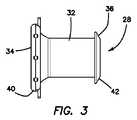
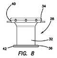
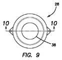
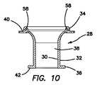
ガード28を袋18の開口部20中に通して内部に挿入する。ガード28は、切開創/開口部14内において、ガードを開口部14内に配置したときにガード28が定位置に保たれるような直径を有する。ガード28はまた、組織を切開創/開口部のところでレトラクトすることができ、従って、レトラクタと呼ばれる場合がある。ガード28の一変形例が図2〜図6に示され、別の変形例が図7〜図10に示されている。ガード28は、頂部34と底部36との間で相互に連結された側壁を定める内面30および外面32を有する。内面30は、頂部34と底部36との間に延びる中央ルーメン38を画定している。内面30は、頂部34の近くに位置していて凸状または切頭円錐形であるのが良い湾曲した漏斗状部分を有する。ガード28は、腹壁10の上面および下面にそれぞれ衝合する表面を作るよう半径方向外方に延びる頂部円周方向フランジ40および底部円周方向フランジ42を有している。頂部フランジ40は、例えばテザー22を通してガード28を袋18に固定するための孔のような特徴部を有するのが良い。ガード28は、約2.5インチ(6.35cm)の全長を有するが、種々の長さのガード28を穿通されるべき組織壁10の厚さに応じて用いることができる。可変長さのガード28、例えば伸縮または入れ子式ガード28は、本発明の範囲に含まれる。中間長さのところでのガード28の内径は、約1.3インチ(3.30cm)であり、これは、約0.6インチ(1.52cm)と同じほど小径であっても良い。中間長さのところにおけるガード28の外径は、約1.6インチ(4.06cm)であり、これは、中間長さのところにおけるガード28の直径に対する頂部円周方向フランジ40の全体的直径が大きいので頂部円周方向フランジ40が定位置に保持されるよう切開創/開口部に適合する。中間長さのところの肉厚は、約0.16インチ(4.06mm)であり、これは、約0.3インチ(7.62mm)と同じほど厚くても良い。ガード28は、任意のポリマー、例えばクラトン(KRATON(登録商標))またはポリエチレンで作られているが、ガードは、金属を含む任意適当な材料で作られても良い。ガード28は、腹壁10の開口部14を通る挿入を容易にするためにガード28を僅かに圧縮することができるよう可撓性であるのが良い。ガード28の厚さおよび/またはガード28の構成材料の選択肢は、ガード28がブレード、ナイフ、小刀、細切器等からの切断および穴あけ力に耐えることができるよう選択される。ガード28は、取り出しに先立って切断するために標的組織を当てる切断板または表面として働く。標的組織16を腹腔鏡把持器で掴みそして開口部14に向かって上方に引き上げる。次に、切断されるべき標的組織16の少なくとも一部分をガード28の長さに沿うどこかの場所でガード28の配置場所の定位置に保持する。次に、ブレード、例えば小刀または細切器をガード28の配置場所で切断されるべき標的組織の部分に接触させ、そして標的組織のこの部分を切断する。開口部14を通って標的組織の切断部分を患者の体外の表面まで引き上げ、そして標的組織の新たな区分をガード28に沿う位置に至らせて切断して取り出す。このプロセスを繰り返し実施し、ついには、検体全体が袋18から丸ごとまたは部分的に取り出されるようにする。ガード28は、袋18の保護手段としての役目を果たす。医師は、ガード28の配置場所でそして更にガードの内面30に当てた状態で標的組織を自由に切断することができ、それにより小刀または細切器による袋18の切断結果を切断の影響を軽減する。ガード28は、検体回収袋18を偶発的な切開から保護するだけでなく、ガード28は、周囲の組織、例えば腹壁を偶発的な切開から保護する。ガード28は、袋18の健全性を保つとともに閉鎖式切開システムを効果的に維持する。外科医は、検体を迅速かつ安全に縮小し、そしてこれを腹腔から取り出すことができる。 Theguard 28 is passed through theopening 20 of thebag 18 and inserted into thebag 18. Theguard 28 has a diameter within the incision /opening 14 such that theguard 28 is held in place when the guard is placed within theopening 14. Theguard 28 can also retract tissue at the incision / opening and is therefore sometimes referred to as the retractor. One modification of theguard 28 is shown in FIGS. 2 to 6, and another modification is shown in FIGS. 7 to 10. Theguard 28 has aninner surface 30 and anouter surface 32 that define the side walls that are interconnected between the top 34 and the bottom 36. Theinner surface 30 defines acentral lumen 38 extending between the top 34 and the bottom 36. Theinner surface 30 has a curved funnel-shaped portion that is located near the apex 34 and is preferably convex or truncated conical. Theguard 28 has a topcircumferential flange 40 and a bottomcircumferential flange 42 that extend radially outward to form surfaces that abut against the top and bottom surfaces of theabdominal wall 10, respectively. Thetop flange 40 may have features such as holes for fixing theguard 28 to thebag 18 through, for example, thetether 22. Theguard 28 has a total length of about 2.5 inches (6.35 cm), but can be used depending on the thickness of thetissue wall 10 through which theguards 28 of various lengths should be penetrated. Variable length guards 28, such as telescopic or nestedguards 28, are within the scope of the invention. The inner diameter of theguard 28 at the intermediate length is about 1.3 inches (3.30 cm), which may be as small as about 0.6 inches (1.52 cm). The outer diameter of theguard 28 at the intermediate length is about 1.6 inches (4.06 cm), which is the overall diameter of the topcircumferential flange 40 relative to the diameter of theguard 28 at the intermediate length. Fits the incision / opening so that the topcircumferential flange 40 is held in place due to its large size. The wall thickness at the intermediate length is about 0.16 inches (4.06 mm), which may be as thick as about 0.3 inches (7.62 mm). Theguard 28 is made of any polymer, eg Kraton® or polyethylene, but the guard may be made of any suitable material, including metals. Theguard 28 should be flexible so that theguard 28 can be slightly compressed to facilitate insertion through theopening 14 of theabdominal wall 10. The choice ofguard 28 thickness and / orguard 28 constituent material is selected so that theguard 28 can withstand cutting and drilling forces from blades, knives, swords, shavings, and the like. Theguard 28 acts as a cutting plate or surface against which the target tissue is applied for cutting prior to removal. Thetarget tissue 16 is grabbed with a laparoscopic grasper and pulled upward towards theopening 14. Next, at least a part of thetarget tissue 16 to be cut is held in place at the place where theguard 28 is placed somewhere along the length of theguard 28. A blade, such as a knife or shredder, is then brought into contact with a portion of the target tissue to be cut at the location of theguard 28, and this portion of the target tissue is cut. A cut portion of the target tissue is pulled up to a surface outside the patient's body through theopening 14, and a new section of the target tissue is cut and removed along theguard 28. This process is repeated until the entire sample is removed from thebag 18 in whole or in part. Theguard 28 serves as a protective means for thebag 18. The physician is free to cut the target tissue at the location of theguard 28 and further against theinner surface 30 of the guard, thereby reducing the effect of cutting thebag 18 with a knife or shredder. To do. Theguard 28 not only protects thespecimen collection bag 18 from accidental incisions, but theguard 28 also protects the surrounding tissue, such as the abdominal wall, from accidental incisions. Theguard 28 maintains the health of thebag 18 and effectively maintains the closed incision system. The surgeon can quickly and safely shrink the specimen and remove it from the abdominal cavity.

ガード28をいったん配置すると、外科医は、検体16を掴んでできるだけ遠くまで切開創を通ってこれを引き上げる。次に、外科医は、小刀26による検体16の細切を開始し、検体16を切断してそのサイズを小さくする。理想的には、外科医は、検体16を「くりぬき」または「剥ぎ取って」、検体をできるだけ多く一体に保つ。しかしながら、5割を超える確率で、検体16は、多数の小片の状態になる。切開創を通る状態での細切を行っている間、外科医は、腹腔12内の気腹状態を維持することができ、その結果、細切の進捗状況を二次部位のところで腹腔12内に配置された側方ポートを通って腹腔鏡下で観察することができる。側方ポートは、袋18の外部に位置し、外科医は、透明な袋越しにまたは袋それ自体のところで見ることができ、それにより袋がその健全性を維持するようにすることができる。いったん検体16を切開創中に通して残りの部分を引き出すのに十分細切し、破砕し、縮小させると、ガード28を取り出し、袋18および細切中に生じた小片を含むその内容物を患者から引き出す。袋18は、残りの小片が腹腔12内に残るのを阻止し、閉鎖系を保ち、これに対し、伝統的な細切法では、外科医は、戻って骨盤腔の中の散らばった小片を苦心して探して集めて新たな腫瘍部位を潜在的に播種するのを阻止しなければならない。外科医は、腹腔鏡下で患者を最終的に見るのを選択し、次に創部を閉じることができる。 Once theguard 28 is in place, the surgeon grabs thespecimen 16 and pulls it up through the incision as far as possible. The surgeon then begins chopping thespecimen 16 with theknife 26 and cutting thespecimen 16 to reduce its size. Ideally, the surgeon "hollows out" or "strips" thespecimen 16 to keep the specimens together as much as possible. However, with a probability of more than 50%, thesample 16 is in the state of a large number of small pieces. While performing the chopping through the incision, the surgeon can maintain a pneumoperitoneum in theabdominal cavity 12 so that the progress of the chopping is in theabdominal cavity 12 at the secondary site. It can be observed laparoscopically through the arranged lateral port. The lateral port is located on the outside of thebag 18 and can be seen by the surgeon through the transparent bag or at the bag itself, thereby allowing the bag to maintain its health. Once thespecimen 16 has been chopped enough to pull out the rest through the incision, crushed and shrunk, theguard 28 is removed and the patient takes out thebag 18 and its contents, including the small pieces generated during the chopping. Pull out from. Thebag 18 prevents the remaining pieces from remaining in theabdominal cavity 12 and keeps the closed system, whereas in traditional shredding, the surgeon goes back and suffers from scattered pieces in the pelvic cavity. It must be carefully sought, collected and prevented from potentially disseminating new tumor sites. The surgeon may choose to finally see the patient under laparoscope and then close the wound.

腹部取り出しおよび細切について説明したが、上述の手技は、子宮頸を摘出した場合にも膣口を経ることによっても実施することができる。同一のプロセスに続き、袋18を導入し、検体16を腹腔鏡下で袋18内に入れる。腹壁開口部14を通ってテザー22を引くのではなく、膣を通ってこれを引く。同じ仕方で、検体16は、膣の底のところに着座する一方で、袋18は、膣を通って進んで患者の体外で開く。外科医は、袋18を巻き下げまたはこれをぴんと張った状態に引いてその位置を維持するとともに幾分かのレトラクションをもたらすのが良い。外科医は、ガード28を膣経由で配置して袋18の健全性を保護するとともに閉鎖系を維持し、検体16を掴んでこれを取り出し、そして細切して検体16のサイズを減少させる。検体の細切は、ガード28の配置場所でかつ/あるいはガード28の表面に当てた状態で実施し、それにより周囲の組織および袋を偶発的な切開から保護する。外科医は、気腹状態を維持するとともに細切の進捗状況を腹腔鏡下で観察することができる。いったん検体16を膣中に通して残りの部分を引き出すのに十分細切し、破砕し、縮小させると、ガード28を取り出し、袋18および細切中に生じた小片を含むその内容物を患者から引き出す。袋18は、残りの小片が腹腔内に残されるのを阻止し、それにより有害な物質、例えば癌細胞が腹腔内に播種されるのを阻止し、閉鎖系を維持し、これに対し、伝統的な細切法では、外科医は、戻って骨盤腔中に散らばった小片を苦心して探して集めるとともに骨盤腔中に小片があるかないかを調べなければならない。外科医は、患者を腹腔鏡下で最終的に見るのを選択することができ、そして膣カフおよび腹部切開創を閉じる。 Although the abdominal removal and shredding have been described, the above procedure can be performed either by removing the cervix or through the vaginal opening. Following the same process, thebag 18 is introduced and thesample 16 is placed in thebag 18 laparoscopically. Instead of pulling thetether 22 through the abdominal wall opening 14, pull it through the vagina. In the same way, thespecimen 16 sits at the bottom of the vagina, while thebag 18 travels through the vagina and opens outside the patient's body. The surgeon should pull thebag 18 down or pull it taut to maintain its position and provide some retraction. The surgeon places aguard 28 via the vagina to protect the health of thebag 18 and maintain a closed system, grab thespecimen 16 and remove it, and chop it down to reduce the size of thespecimen 16. Specimen shredding is performed at the location of theguard 28 and / or in contact with the surface of theguard 28, thereby protecting the surrounding tissue and bag from accidental incisions. The surgeon can maintain the pneumoperitoneum and observe the progress of the shredding laparoscopically. Once thespecimen 16 has been shredded enough to pull out the rest through the vagina, crushed and shrunk, theguard 28 is removed and its contents, including thebag 18 and the small pieces generated during the shredding, are removed from the patient. Pull out. Thesac 18 prevents the remaining pieces from being left in the abdominal cavity, thereby preventing harmful substances such as cancer cells from being disseminated into the abdominal cavity and maintaining a closed system, whereas traditional In a typical shredding method, the surgeon must go back and painstakingly search for and collect the pieces scattered in the pelvic cavity and check for small pieces in the pelvic cavity. The surgeon can choose to finally see the patient under laparoscope and close the vaginal cuff and abdominal incision.

図11に示された一変形例では、ガード28は、キャップ44、例えばカリフォルニア州所在のアプライド・メディカル・リソーシーズ・コーポレイション(Applied Medical Resources Corporation)によって製造されたゲルシール(GELSEAL(登録商標))キャップに取り付けられるよう構成されている。キャップ44は、ガード28の近位端部に取り外し可能に連結可能な剛性リング46を有する。キャップ44は、キャップ44をガード28にロックするためのレバー48を有する。キャップ44は、このキャップを通って挿入された器械に密着して腹腔内の気腹状態を維持するよう構成されたゲルで構成可能な穿通可能部分50を有する。図12および図13は、ガード28に連結されたキャップ44を示している。想起ポート52がキャップ44に設けられるのが良い。キャップ44は、ガード28にスナップ装着され、そしてレバーロック48によってこれに密封的にロックされるのが良く、その結果、気腹状態が維持されるようになる。図14は、多数のポート54を備えたキャップ44を示している。各ポート54は、腹腔鏡器械を受け入れるよう構成されており、各ポートは、挿入状態の器械に密着するための1つまたは2つ以上の内部シールを有する。多ポート型キャップ44は、有利には、単一の部位を通る把持器、腹腔鏡および/または細切器の挿入を可能にする。 In one variant shown in FIG. 11, theguard 28 is attached to acap 44, eg, a GELSEAL® cap manufactured by Applied Medical Resources Corporation in California. It is configured to be installed. Thecap 44 has arigid ring 46 that is removable and connectable to the proximal end of theguard 28. Thecap 44 has alever 48 for locking thecap 44 to theguard 28. Thecap 44 has aperforable portion 50 made of a gel configured to adhere to the instrument inserted through the cap and maintain a pneumoperitoneum in the abdominal cavity. 12 and 13 show acap 44 connected to aguard 28. Therecall port 52 should be provided on thecap 44. Thecap 44 is preferably snap-mounted to theguard 28 and hermetically locked to it by thelever lock 48, so that the pneumoperitoneum is maintained. FIG. 14 shows acap 44 with a large number ofports 54. Eachport 54 is configured to receive a laparoscopic instrument, and each port has one or more internal seals for close contact with the inserted instrument. Themulti-port cap 44 advantageously allows insertion of grippers, laparoscopes and / or shredders through a single site.

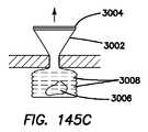
図15〜図17は、ガード28の別の変形例を示しており、この変形例は、ガード28の遠位端部のところにバルーン56を有している。バルーン56は、図15ではインフレート形態で示されている。インフレート形態では、バルーン56は、腹腔12内の腹壁10に固着するための幅広のフランジを形成するよう半径方向外方に延びており、それにより、ガード28が開口部14から偶発的に取り出されるのを困難にしている。図16は、バルーンをガード28が開口部14中に容易に挿入されたりこの開口部から容易に取り出されたりするデフレート形態で示している。図15〜図17のガード28もまた、キャップ44に連結されるのが良い。ガード28は、ポリカーボネートまたはこれに類似した材料を含む任意のポリマー材料で構成できる。 15 to 17 show another variant of theguard 28, which has aballoon 56 at the distal end of theguard 28. Theballoon 56 is shown in inflated form in FIG. In the inflated form, theballoon 56 extends radially outward to form a wide flange for anchoring to theabdominal wall 10 within theabdominal cavity 12, whereby theguard 28 is accidentally removed from theopening 14. It makes it difficult to be. FIG. 16 shows the balloon in a deflate form in which theguard 28 is easily inserted into and removed from theopening 14. Theguard 28 of FIGS. 15 to 17 may also be connected to thecap 44. Theguard 28 can be made of any polymeric material, including polycarbonate or similar materials.

ガード28の近位端部のところに設けられた漏斗状エントリについては上述した。漏斗状エントリは、広い表面領域を形成するよう別の変形例では半径方向外方に拡大されるのが良く、組織をこの広い表面領域に当てた状態で切断することができる。ラッパ形近位端部はまた、袋を患者の体外のかつガード28と組織辺縁10との間の定位置に保持するのを助ける。別の変形例では、ガード28は、形状が切頭円錐形または湾曲したラッパ形遠位端部を有する。ラッパ形遠位端部は、袋18を腹腔内で側方に広げる拡大された状態の半径方向に延びるフランジを有するのが良い。ラッパ形遠位端部は、袋を開放位置に保つとともに検体と接触しないよう離れてかつガード28への遠位エントリから離れて保つのを助け、それにより、袋18をブレードとの偶発的な接触から保護する。ガード28のラッパ形遠位端部変形例では、遠位開口部のところのガード28の遠位直径は、中間長さのところのガード28の直径よりも大きい。ガード28のラッパ形近位端部変形例では、近位開口部のところのガードの近位直径は、中間長さのところのガード28の直径よりも大きい。さらに別の変形例では、ガード28は、上述の変形例の利点を保持するラッパ形近位端部およびラッパ形遠位端部を有する。 The funnel-shaped entry provided at the proximal end of theguard 28 has been described above. The funnel-shaped entry may be expanded radially outward in another variant to form a large surface area, and the tissue can be cut in contact with this large surface area. The trumpet-shaped proximal end also helps hold the bag in place outside the patient's body and between theguard 28 and thetissue margin 10. In another variant, theguard 28 has a truncated conical or curved trumpet-shaped distal end. The trumpet-shaped distal end preferably has a flange extending radially in an enlarged state that spreads thebag 18 laterally within the abdominal cavity. The trumpet-shaped distal end helps keep the bag open and away from contact with the specimen and away from the distal entry to theguard 28, thereby keeping thebag 18 accidentally with the blade. Protect from contact. In the trumpet-shaped distal end variant of theguard 28, the distal diameter of theguard 28 at the distal opening is larger than the diameter of theguard 28 at the intermediate length. In the trumpet-shaped proximal end variant of theguard 28, the proximal diameter of the guard at the proximal opening is larger than the diameter of theguard 28 at the intermediate length. In yet another variant, theguard 28 has a trumpet-shaped proximal end and a trumpet-shaped distal end that retains the advantages of the aforementioned variant.

次に、キャップ44を備えたガード28を用いる組織の取り出し方法について説明する。腹腔鏡下子宮摘出術または任意他の切離を完了した後、上述の検体16は、周囲組織から完全に剥離されていて取り出しを待っている。外科医は、骨盤に対して透明であるのが良い検体袋18を挿入して検体16をこの袋18内に配置する。次に、外科医は、袋18に取り付けられているテザー22を、腹腔鏡把持器を用いて掴んで袋18を引き上げ、トロカールが既に配置されている腹壁切開創14中に引く。必要ならば、外科医は、袋を完全に引き通す前に切開創を15〜25mmに拡張する。検体16が大きすぎて開口部14に嵌まった状態で通過することができないので、検体16は、骨盤腔の内側で腹壁10の真下に位置し、他方、袋18の残部は、切開創から引き出されて図1に示されているように患者の体外で開かれる。外科医は、袋を巻き下げまたはこれをぴんと張った状態に引いてその位置を維持するとともに幾分かのレトラクションを提供することができる。次に、外科医は、ガード28を切開創中に挿入して袋18および腹壁10を細切中保護するとともに切開創をレトラクトする。袋の健全性が保たれ、閉鎖系が維持される。 Next, a method of taking out the tissue using theguard 28 provided with thecap 44 will be described. After completing a laparoscopic hysterectomy or any other dissection, thespecimen 16 described above has been completely detached from the surrounding tissue and awaits removal. The surgeon inserts asample bag 18, which should be transparent to the pelvis, and places thesample 16 in thebag 18. The surgeon then grabs thetether 22 attached to thebag 18 with a laparoscopic grasper, pulls thebag 18 up, and pulls it into theabdominal wall incision 14 where the trocar is already located. If necessary, the surgeon dilates the incision to 15-25 mm before fully threading the bag. Thespecimen 16 is located inside the pelvic cavity, just below theabdominal wall 10, because thespecimen 16 is too large to pass through in theopening 14 while the rest of thebag 18 is from the incision. It is pulled out and opened outside the patient's body as shown in FIG. The surgeon can roll the bag down or pull it taut to maintain its position and provide some retraction. The surgeon then inserts aguard 28 during the incision to protect thebag 18 and theabdominal wall 10 during the incision and retract the incision. The health of the bag is maintained and the closed system is maintained.

ガード28を袋18の開口部28内に配置し、そして切開創内に位置決めし、その結果、ガード28が組織辺縁10を横切って延びるようにする。キャップ44をガード28に連結する。キャップ44は、近位頂部フランジ40にスナップ装着し、キャップ44のレバー48をロック位置に動かしてキャップ44をガード28に密着させる。ガード28は、頂部フランジ40の形状および剛性を維持するよう補強ワイヤ58を有するのが良い。ワイヤ58は、図1、図5、図6、図10および図12に見える。キャップ44が定位置にある状態で、袋18に送気するのが良い。一変形例では、袋18にのみ送気してこれを腹腔12に対して膨らます。別の変形例では、袋18と腹腔12の両方に送気する。別の変形例では、袋18と腹腔12の両方に送気し、袋18内の圧力が腹腔12の送気圧力よりも高くなるようにする。送気は、キャップ44を通って挿入されたトロカールを介してまたはキャップ44の送気ポート52を経て行われるのが良い。キャップ44が定位置にある状態で、電動式細切器24をキャップ44の穿通可能部分50中に通して袋18の内部中に挿入する。変形例として、多ポート型キャップ44が用いられる場合、細切器24をポート54のうちの1つに通して挿入するのが良い。外科用把持器もまた、穿通可能部分50かポート54のうちの1つを通るかのいずれかからキャップ44中に挿入し、そして標的組織を掴んで開口部に向かって近位側に引いてガード28の中央ルーメン38中に引き込み、ここで、標的組織をガード28によって提供された保護ゾーン内で細切する。上述したように、ガード28は、袋18が穴あけされないよう保護し、それにより、閉鎖細切系を維持するのを助ける。電動式細切器24を、電動式細切器24のブレード付き遠位端部60を中央ルーメン38およびガード28の保護領域または保護長さ中に維持する深さまでゲルキャップ44に通して配置する。細切および取り出しのために把持器により標的組織をブレード60の方へ引き寄せる。取り出された組織は、電動式細切器24の中央ルーメンを通って移動することになる。 Theguard 28 is placed within theopening 28 of thebag 18 and positioned within the incision so that theguard 28 extends across thetissue margin 10. Thecap 44 is connected to theguard 28. Thecap 44 is snap-mounted on the proximaltop flange 40 and moves thelever 48 of thecap 44 to the locked position to bring thecap 44 into close contact with theguard 28. Theguard 28 preferably has a reinforcingwire 58 to maintain the shape and rigidity of thetop flange 40. Thewire 58 is visible in FIGS. 1, 5, 6, 10, and 12. It is good to supply air to thebag 18 with thecap 44 in place. In one variant, only thebag 18 is inflated to theabdominal cavity 12. In another variant, air is delivered to both thebag 18 and theabdominal cavity 12. In another modification, air is supplied to both thebag 18 and theabdominal cavity 12 so that the pressure inside thebag 18 is higher than the air pressure of theabdominal cavity 12. The air supply is preferably carried out via the trocar inserted through thecap 44 or through theair supply port 52 of thecap 44. With thecap 44 in place, theelectric shredder 24 is passed through the piercingportion 50 of thecap 44 and inserted into thebag 18. As a modification, when themulti-port cap 44 is used, it is preferable to insert theshredder 24 through one of theports 54. The surgical gripper is also inserted into thecap 44 from either through thepenetrable portion 50 or through one of theports 54, and grabs the target tissue and pulls it proximally towards the opening. It is retracted into thecentral lumen 38 of theguard 28, where the target tissue is chopped within the protection zone provided by theguard 28. As mentioned above, theguard 28 protects thebag 18 from being punctured, thereby helping to maintain a closed shredding system. Theelectric shredder 24 is placed through thegel cap 44 to a depth that maintains the bladeddistal end 60 of themotorized shredder 24 within the protective area or protective length of thecentral lumen 38 andguard 28. .. A gripper pulls the target tissue towards theblade 60 for shredding and removal. The removed tissue will move through the central lumen of theelectric shredder 24.

細切器24をキャップ44の穿通可能部分50に通して配置するのではなく、袋18またはガード28と協働して細切器24をガード28の中央ルーメン38内の保護ゾーン内の或る深さのところの定位置に保持するのに役立つ安定器を用意する。細切器をガード28のルーメン38内に維持することにより、細切器24は、この手技中、袋18の壁に接触するのが阻止され、それにより、袋は、偶発的な裂けが生じないよう保護される。以下において、安定器の変形例について更に説明する。 Rather than placing theshredder 24 through theperforable portion 50 of thecap 44, there is ashredder 24 in a protective zone within thecentral lumen 38 of theguard 28 in cooperation with thebag 18 orguard 28. Provide a ballast to help hold it in place at depth. By keeping the shredder in thelumen 38 of theguard 28, theshredder 24 is prevented from contacting the wall of thebag 18 during this procedure, which causes the bag to accidentally tear. Protected from not. Hereinafter, a modified example of the ballast will be further described.

細切器24およびキャップ44を配置した後、外科医は、袋18ならびに腹腔12に送気するのを選択するのが良い。外科医は、細切器24および標的組織16の位置ならびに袋18の健全性を観察することができ、それにより袋がねじれておらずまたは細切器24の遠位端部60に近すぎるほど接近していないことを確認する。観察は、同じ切開創部位のところのポート54を通ってまたは側方ポートとなる二次切開創部位を通って配置された腹腔鏡により行われる。検体16を支持鉤(tenaculum:テナキュラム)で掴んで電動式細切器24中に引き込んでそのサイズを減少させる。理想的には、外科医は、標的組織を「くりぬき」または「剥ぎ取って」これをできるだけ一体の状態に保つ。しかしながら、5割以上の確率で標的組織は、多数の小片になる。残りの組織を切開創中に引き通すのに十分に検体16をいったん細切すると、細切器24、ゲルキャップ44または安定器、およびガード28レトラクタを抜去し、袋18および細切中に生じた小片を含むその内容物を患者から引き出す。袋18は、残りの小片が腹腔12内に残されるのを阻止し、閉鎖系を維持し、これに対し、伝統的な細切法では、外科医は、戻って骨盤腔の中の散らばった小片を苦心して探して集めて新たな腫瘍部位を潜在的に播種するのを阻止しなければならない。外科医は、腹腔鏡下で患者を最終的に見るのを選択し、次に創部を閉じる。 After placing theshredder 24 andcap 44, the surgeon may choose to inflate into thebag 18 and theabdominal cavity 12. The surgeon can observe the location of theshredder 24 and thetarget tissue 16 as well as the health of thebag 18 so that the bag is not twisted or is too close to thedistal end 60 of the shredder 24. Make sure you haven't. Observations are made by a laparoscope placed through aport 54 at the same incision site or through a secondary incision site that becomes a lateral port.Specimen 16 is grabbed by a tenaculum and pulled into anelectric shredder 24 to reduce its size. Ideally, the surgeon "hollows out" or "strips" the target tissue to keep it as cohesive as possible. However, with a probability of 50% or more, the target tissue becomes a large number of small pieces. Oncespecimen 16 was shredded enough to allow the remaining tissue to pass through the incision, theshredder 24,gel cap 44 or ballast, andguard 28 retractor were removed and occurred duringbag 18 and shredding Withdraw its contents, including small pieces, from the patient. Thebag 18 prevents the remaining pieces from remaining in theabdominal cavity 12 and maintains a closed system, whereas in traditional shredding, the surgeon returns to the scattered pieces in the pelvic cavity. Must be painstakingly sought and collected to prevent the potential dissemination of new tumor sites. The surgeon chooses to finally see the patient under laparoscope and then closes the wound.

腹部取り出しおよび細切について説明したが、上述の電動式細切手技を体口、例えば膣を介しても実施することができる。同一のプロセスに続き、袋18を導入し、検体16を腹腔鏡下で袋18中に入れる。テザー22を、腹壁開口部14を通って引き抜くのではなく、テザー22を、膣を通って引き抜く。同じやり方で、検体16は、膣の底のところに位置し、他方、袋18は、膣を通って進んで患者の体外で開く。外科医は、袋18を巻き下げまたはこれをぴんと張った状態に引いてその位置を維持するとともに幾分かのレトラクションをもたらすのが良い。外科医は、ガード28を膣経由で袋18の中に配置して袋の健全性を保護するとともに閉鎖系を維持し、キャップ44をガード28に被せて電動式細切器24をゲルキャップ44または安定化キャップに通して配置する。外科医は次に、支持鉤で検体16を掴んでこれを電動式細切器24に通して膣経由で出し、それにより検体16のサイズを減少させる。外科医は、気腹状態を維持し、細切の進行状況を腹腔鏡下で観察する。残りの部分を膣に通して引き込むのに十分なほど検体16をいったん細切すると、細切器24、ゲルキャップ44または安定化キャップ、ガード28および/またはレトラクタを取り出し、そして袋18および細切中に生じた小片を含むその内容物を患者から引き出す。袋18は、残りの小片が腹腔12内に残されるのを阻止し、閉鎖細切システムを維持し、これに対し、伝統的な細切法では、外科医は、戻って骨盤腔中に散らばった小片を苦心して探して集めるとともに骨盤腔中に小片があるかないかを調べなければならない。外科医は、患者を腹腔鏡下で最終的に見るのを選択することができ、そして膣カフおよび腹部切開創を閉じる。 Although the abdominal removal and shredding have been described, the electric shredding procedure described above can also be performed through the body mouth, for example the vagina. Following the same process, thebag 18 is introduced and thesample 16 is laparoscopically placed in thebag 18. Instead of pulling thetether 22 through the abdominal wall opening 14, thetether 22 is pulled through the vagina. In the same manner,specimen 16 is located at the bottom of the vagina, whilebag 18 travels through the vagina and opens outside the patient's body. The surgeon should pull thebag 18 down or pull it taut to maintain its position and provide some retraction. The surgeon places theguard 28 through the vagina into thebag 18 to protect the health of the bag and maintain a closed system, and thecap 44 is placed over theguard 28 and theelectric shredder 24 is placed on thegel cap 44 or Place through the stabilizing cap. The surgeon then grabs thespecimen 16 with a support hook and passes it through anelectric shredder 24 through the vagina, thereby reducing the size of thespecimen 16. The surgeon maintains pneumoperitoneum and observes the progress of the shredding laparoscopically. Once thespecimen 16 has been shredded enough to pull the rest through the vagina, theshredder 24,gel cap 44 or stabilization cap,guard 28 and / or retractor are removed, and thebag 18 and in chopping Withdraw from the patient its contents, including the small pieces produced in. Thebag 18 prevented the remaining pieces from being left in theabdominal cavity 12 and maintained a closed shredding system, whereas in traditional shredding, the surgeon returned and scattered throughout the pelvic cavity. You must painstakingly search for and collect the pieces and check for small pieces in the pelvic cavity. The surgeon can choose to finally see the patient under laparoscope and close the vaginal cuff and abdominal incision.

次に図18および図19を参照すると、可撓性側壁68によって互いに連結された第1のリング64と第2のリング66を有するレトラクタ62が示されている。レトラクタ62については本出願において参照により組み込んだ特許文献のうちの1つまたは2つ以上に詳細に説明されている。第2のリング66を圧縮して小さな切開創に通して挿入するのが良く、この小さな切開創において第2のリング66が拡張して腹腔12内の腹壁10への固着手段を形成する。第1のリング64は、患者の体外で腹腔10の上に位置し、この場所で第1のリングをそれ自体回しながらまたはひっくり返しながら下げると、腹壁開口部14をレトラクトして広げることができる。レトラクタ62を上述の変形例のうちの任意のものに採用することができる。使用にあたり、レトラクタ62を体腔または体口中への袋18の挿入に先立って挿入する。一変形例では、第1のリング64は、図19に示されているように第2のリング66よりも大きな直径を有する。第2のリング66に対して大径の第1のリング64により、広い空間で作業して組織を切断することができる。側壁68は、ポリウレタンラミネートまたは側壁68の切断に抵抗する不織布を含む類似の材料で作られている。 Next, with reference to FIGS. 18 and 19, aretractor 62 having afirst ring 64 and asecond ring 66 connected to each other by aflexible side wall 68 is shown. Theretractor 62 is described in detail in one or more of the patent documents incorporated by reference in this application. Thesecond ring 66 may be compressed and inserted through a small incision, in which thesecond ring 66 expands to form a means of anchoring to theabdominal wall 10 in theabdominal cavity 12. Thefirst ring 64 is located outside the patient's body above theabdominal cavity 10, where the first ring can be retracted and widened by lowering the first ring by itself or by turning it over. .. Theretractor 62 can be used in any of the above modifications. In use, theretractor 62 is inserted prior to the insertion of thebag 18 into the body cavity or mouth. In one variant, thefirst ring 64 has a larger diameter than thesecond ring 66, as shown in FIG. Thefirst ring 64, which has a larger diameter than thesecond ring 66, allows the tissue to be cut by working in a large space. Theside wall 68 is made of a similar material, including a polyurethane laminate or a non-woven fabric that resists cutting of theside wall 68.

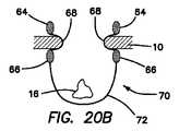
図20Aおよび図20Bは、袋70中に構成された改造型レトラクタ62を示している。袋70は、可撓性で実質的に円筒形の側壁68により互いに連結された第1のリング64と第2のリング66を有している。第2のリング66のところの開口部は、袋70の基部72を形成する垂下袋部分によって閉じられている。袋70を袋18に関して上述したのと同じ仕方で挿入して同じ仕方で用いる。第2のリング66を圧縮し、そしてこれを小さな切開創に通して腹腔12中に送り込む。側壁68を頂部リング64周りに巻いて開口部14をレトラクトするとともにこれを開き、第1のリング64に連結可能なガード24を袋70内の開口部のところで用いても良くあるいは用いなくても良い。検体16を上述したのと同じやり方で手動または電動式細切によって取り出す。第1のリング64もまた、ゲルキャップ44に連結可能である。 20A and 20B show a modifiedretractor 62 configured in thebag 70. Thebag 70 has afirst ring 64 and asecond ring 66 connected to each other by a flexible, substantiallycylindrical side wall 68. The opening at thesecond ring 66 is closed by a hanging bag portion that forms thebase 72 of thebag 70. Thebag 70 is inserted in the same manner as described above for thebag 18 and used in the same manner. Thesecond ring 66 is compressed and delivered into theabdominal cavity 12 through a small incision. Theside wall 68 may or may not be used at the opening in thebag 70 by winding theside wall 68 around thetop ring 64 to retract and open theopening 14 and connect theguard 24 to thefirst ring 64. good.Specimen 16 is removed manually or by electric shredding in the same manner as described above. Thefirst ring 64 can also be connected to thegel cap 44.

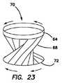
次に、図21〜図24を参照すると、開口部を形成する第1のリング64、可撓性で円筒形の側壁68および基部72だけを備えた袋70が示されている。第1のリング64は、弾性でありかつ小さな切開中にまたはトロカールのルーメンを通って進むのに適した潰れ状態の細長い形態に圧縮可能である。図22に示された矢印は、袋70の垂直潰れ方向を示している。次に、潰れた状態の袋70をその後に側方に容易に圧縮し、そして腹腔内に配備する。第1のリング64を圧縮してこれを細長い形状にする。圧縮状態の袋は、第1のリング64が拡張した状態の元の形状を形成するようになる。拡張形態では、袋70は、腹腔12内で容易に配向される。潰れ状態の袋70は、腹腔内で好都合にも平べったい状態になり、この袋は、2つの側部を有する。袋70は潰れ形態では、表が上になっていない。というのは、いずれの側部を用いても検体を第1のリング64の境界部内に配置することができるからである。第1のリング64は、検体配置のための周囲案内としての役目を果たし、第1のリングは、これを腹腔鏡で容易に観察することができるよう明るく色分けされるのが良い。検体を第1のリング64の周囲内に配置した後、第1のリング64を掴んでこれを持ち上げて検体を袋70内に配置する。同じことは、上述の2リング形袋70についても言える。図23および図24に示されているように、袋70をねじって渦巻き形態を形成して潰しまたは袋の長さを短くしても良い。この特徴は、小さな切開創を通る袋の挿入にとって有利であるだけでなく、検体を細切しているときに検体を袋の開口部の近くに持ち上げるのに有利である。 Next, referring to FIGS. 21 to 24, abag 70 with only afirst ring 64 forming an opening, a flexible,cylindrical side wall 68 and abase 72 is shown. Thefirst ring 64 is elastic and can be compressed into a collapsed elongated form suitable for traveling during a small incision or through the lumen of a trocar. The arrow shown in FIG. 22 indicates the vertical collapse direction of thebag 70. The crushedbag 70 is then easily compressed laterally and placed intraperitoneally. Thefirst ring 64 is compressed into an elongated shape. The compressed bag will form the original shape with thefirst ring 64 expanded. In the expanded form, thebag 70 is easily oriented within theabdominal cavity 12. The crushedbag 70 is conveniently flattened in the abdominal cavity, and the bag has two sides. Thebag 70 is in a crushed form, and the front side is not turned up. This is because the sample can be placed within the boundary of thefirst ring 64 using either side. Thefirst ring 64 serves as a peripheral guide for specimen placement, and the first ring should be brightly color coded so that it can be easily observed with a laparoscope. After the sample is placed around thefirst ring 64, thefirst ring 64 is grabbed and lifted to place the sample in thebag 70. The same can be said for the above-mentioned two-ring bag 70. As shown in FIGS. 23 and 24, thebag 70 may be twisted to form a spiral shape and crushed or the length of the bag may be shortened. This feature is not only advantageous for inserting the bag through a small incision, but also advantageous for lifting the sample near the opening of the bag when chopping the sample.

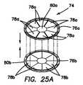
次に図25を参照すると、図18および図19に示されたレトラクタ62または図20〜図24の袋70と併用可能に構成されているガード74が示されている。ガード74は、剛性リング76を有し、複数の内方に延びるフラップ78が中心で出会い、または図25に示されているように中心に開口部80を形成する。フラップ78は、これらフラップがリング76に対して撓むようにリング76に取り付けられており、それにより、標的組織16を、フラップ78を越えて取り出すことができる。フラップ78はまた、遠位側に撓んでガードを越えて器械を挿入することができる。フラップ78は、ガード28の同種の材料、例えばポリカーボネート、LDPE、HDPEまたは類似の材料で作られており、従って、フラップ78は、十分に弾性であって耐切断性を示すとともにブレードによる穿通に抵抗し、それにより、レトラクタ62または袋70を保護する。ガード74は、フラップ78を備えた単一のリング76から成っていても良くあるいはフラップ78a,78bをそれぞれ備えた2つの類似のリング76a,76bで構成されても良い。2つのリング76a,76bは、フラップ78aがフラップ78bからオフセットしてフラップ78a,78b相互間の保護を可能にする層状フラップ構成体を形成するよう互いに連結されている。標的組織16は、開口部80a,80bを通って引き上げられ、ガード76の付近にあるとき、標的組織16が切断される。標的組織16はまた、フラップ78a,78bに当てて位置決めされた場合にも切断可能である。 Next, with reference to FIG. 25, aguard 74 configured to be used in combination with theretractor 62 shown in FIGS. 18 and 19 or thebag 70 of FIGS. 20-24 is shown. Theguard 74 has a rigid ring 76 in which a plurality of inwardly extending flaps 78 meet at the center or form anopening 80 at the center as shown in FIG. The flaps 78 are attached to the ring 76 so that these flaps bend with respect to the ring 76, whereby thetarget tissue 16 can be removed beyond the flap 78. The flap 78 can also flex distally to insert the instrument over the guard. The flap 78 is made of the same material as theguard 28, such as polycarbonate, LDPE, HDPE or similar material, so the flap 78 is sufficiently elastic and exhibits cutting resistance and resists penetration by blades. And thereby protect theretractor 62 or thebag 70. Theguard 74 may consist of a single ring 76 with flaps 78 or may consist of twosimilar rings 76a, 76b withflaps 78a, 78b, respectively. The tworings 76a, 76b are connected to each other so that theflaps 78a are offset from theflaps 78b to form a layered flap construction that allows protection between theflaps 78a, 78b. Thetarget tissue 16 is pulled up through theopenings 80a, 80b, and when in the vicinity of the guard 76, thetarget tissue 16 is cut. Thetarget tissue 16 can also be cut when positioned against theflaps 78a, 78b.

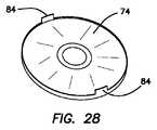
次に図26を参照すると、ガード74は、図29に示されているようにレトラクタ62の第1のリング64または袋70の下にスナップ動作で位置するよう構成された直立した扁平な周囲壁82を有している。ガード74は、図28に示されているようにレトラクタ62の第1のリング64または袋70とスナップ嵌合するよう構成されたフランジ84を更に有するのが良い。図27は、フラップのない剛性ガード74を示している。図27の剛性ガード74は、広い切断面を提供し、標的組織をこの切断面に当てた状態で切断することができ、この場合、可撓性フラップ78を備えたガード74と同じほど多く撓むことはない。ガード74は、袋70/レトラクタ62および/または創部にとって垂直方向に高い保護作用をもたらす漏斗の形をした垂下部分86を更に有するのが良い。ガード74は、レトラクタ62または袋70の頂部上にかつ第1のリング64の周囲内に配置される。次に、ガード74は、ガード74を第1のリング64に接合するよう第1のリング64の下にスナップ装着される。ガード74はまた、細切されているときに穿通に抵抗する材料で作られていて、袋70またはレトラクタ62を定位置に保つのを助ける。他の変形例では、ガードは、リングにスナップ装着するよう構成されている。 Next, referring to FIG. 26, theguard 74 is an upright flat perimeter wall configured to snap under thefirst ring 64 orbag 70 of theretractor 62 as shown in FIG. It has 82. Theguard 74 may further have aflange 84 configured to snap fit to thefirst ring 64 orbag 70 of theretractor 62 as shown in FIG. FIG. 27 shows arigid guard 74 without flaps. Therigid guard 74 of FIG. 27 provides a wide cut surface that allows the target tissue to be cut in contact with the cut surface, in which case it flexes as much as theguard 74 with the flexible flap 78. There is no need for it. Theguard 74 may further have a funnel-shaped droopingportion 86 that provides a high vertical protection for thebag 70 /retractor 62 and / or the wound. Theguard 74 is located on the top of theretractor 62 orbag 70 and within the perimeter of thefirst ring 64. Theguard 74 is then snap-mounted under thefirst ring 64 to join theguard 74 to thefirst ring 64. Theguard 74 is also made of a material that resists penetration when shredded, helping to keep thebag 70 orretractor 62 in place. In another variant, the guard is configured to snap onto the ring.

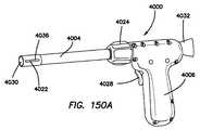
次に図30を参照すると、第1のバルーン90および第2のバルーン92を有するトロカール88が示されている。トロカール88は、挿入状態の器械に密着する1つまたは2つ以上のシールを備えた取り外し可能なシールハウジング94を有する。トロカール88は、シールハウジング94およびトロカール88を貫通して延びる中央ルーメン96を有する。ルーメン96は、電動式細切器24を受け入れるよう寸法決めされるとともに形作られている。トロカール88は、腹壁を穿通するよう構成された栓塞子(図示せず)を更に有するのが良い。トロカール88を上述したゲルキャップ44中に通して挿入することができまたは腹部に設けられた切開創に通して直接挿入することができる。袋18,70をルーメン86に通して配備することができ、そして検体16を袋18,70中に挿入することができる。袋18のテザー22または袋70の第1のリングを切開創に通して引き、そしてトロカール88を再び挿入する。第2のバルーン92をインフレートさせる。インフレート形態では、第2のバルーン92は、側方に延びて袋18,70を側方にかつトロカール88の遠位端部から離れたところに、しかも細切器のブレード付き遠位端部から離れるよう押す。電動式細切器24をトロカール88のルーメン96中に挿入する。細切器24は、細切器24に当接してトロカール88上に形成されている停止部によりトロカール88の遠位端部を越えて延びるのが阻止されるのが良い。支持鉤を細切器24のルーメン中に挿入し、組織を把持して細切器に引き寄せる。組織を切断して検体袋から取り出す。第1のバルーン90をインフレートさせてこれが腹壁の上方に位置するようにする。第1のバルーン90と第2のバルーン92の両方は、トロカール88を腹壁10に対して定位置に保持するのを助ける。図31は、シールハウジング94および少なくとも一方のバルーン92をインフレートさせる送気ポート98を備えた別のトロカール88を示している。 Next, referring to FIG. 30, atrocar 88 having afirst balloon 90 and asecond balloon 92 is shown. Thetrocar 88 has aremovable seal housing 94 with one or more seals that are in close contact with the instrument in the inserted state. Thetrocar 88 has aseal housing 94 and acentral lumen 96 extending through thetrocar 88. Thelumen 96 is sized and shaped to accommodate theelectric shredder 24. Thetrocar 88 may further have an embolus (not shown) configured to penetrate the abdominal wall. Thetrocar 88 can be inserted through thegel cap 44 described above or directly through an incision made in the abdomen.Bags 18, 70 can be deployed throughlumens 86, andspecimen 16 can be inserted intobags 18, 70. Thetether 22 of thebag 18 or the first ring of thebag 70 is pulled through the incision and thetrocar 88 is reinserted. Inflate thesecond balloon 92. In the inflated form, thesecond balloon 92 extends laterally with thebags 18, 70 laterally and away from the distal end of thetrocar 88, and at the bladed distal end of the trocar. Push away from. Theelectric shredder 24 is inserted into thelumen 96 of thetrocar 88. Thetrocar 24 is preferably prevented from extending beyond the distal end of thetrocar 88 by a stop formed on thetrocar 88 in contact with thetrocar 24. A support hook is inserted into the lumen of theshredder 24 to grab the tissue and pull it towards the shredder. The tissue is cut and removed from the sample bag. Thefirst balloon 90 is inflated so that it is located above the abdominal wall. Both thefirst balloon 90 and thesecond balloon 92 help hold thetrocar 88 in place with respect to theabdominal wall 10. FIG. 31 shows anothertrocar 88 with anair supply port 98 that inflates theseal housing 94 and at least oneballoon 92.

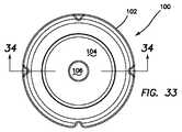
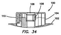
次に図32〜図39を参照して、以下において、安定器100について説明する。安定器100は、袋18,70またはガード28に結合するよう構成されたフランジ102を有する。安定器100は、ルーメン106を構成してロック108を収容する中央部分104を有する。ルーメン106は、電動式細切器24を受け入れるよう寸法決めされるとともに構成されている。ルーメン106中に挿入されると、腹壁に対する細切器24の高さを調節し、次に、細切器をロック108により定位置にロックするのが良い。ロック108は、レバー110が解除されて細切器24がルーメン106内で垂直に並進することができるようにするロック解除形態を有する。ロック108はまた、レバー110を押して細切器24の並進をロックするロック形態を更に有する。ロック108は、ロックを定位置に保持する細切器24のシャフトに対する摩擦力を増大させるよう働く。 Next, theballast 100 will be described below with reference to FIGS. 32 to 39. Theballast 100 has aflange 102 configured to be coupled to thebags 18, 70 orguard 28. Theballast 100 has acentral portion 104 that constitutes thelumen 106 and houses thelock 108. Thelumen 106 is sized and configured to accommodate theelectric shredder 24. Once inserted into thelumen 106, it is preferable to adjust the height of theshredder 24 relative to the abdominal wall and then lock the shredder in place with alock 108. Thelock 108 has an unlocked form that allows thelever 110 to be released and theshredder 24 to translate vertically within thelumen 106. Thelock 108 also has a locking form that locks the translation of theshredder 24 by pushing thelever 110. Thelock 108 acts to increase the frictional force on the shaft of theshredder 24 that holds the lock in place.

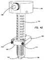
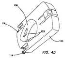
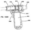
次に図40および図41を参照すると、安定器100は、電動式細切器24に連結された状態で示されている。図40および図41のシステムは、細切器24に設けられていて安定器100の中央部分104内の爪(図示せず)と係合するよう構成された歯付きバーを含むラチェット駆動機構体を有する。ボタン114が爪から離れたり爪に係合したりするよう安定器100に設けられており、その目的は、安定器100を細切器24からロック解除したりこれにロックしてこれらの相対的垂直並進を自由にしまたは阻止することにある。細切器24は、一体形スコープおよび照明器116、送気ポート118および細切器ブレード122を回転させる機械式駆動連結部120を有する。安定器100は、上述したように、袋、レトラクタまたはガードに係合するよう外方に延びる下側フランジ102を有している。一変形例では、安定器100は、安定器の爪が歯付きバー112の或る特定の範囲内に位置し、それにより安全シャットオフ機構体を提供している場合に細切器24の作動が阻止されるよう構成され、その結果、細切器24は、遠すぎまたはガードの範囲を超え、従って、袋との偶発的な接触を生じさせる恐れのある位置にあるときに作動されないようになっている。安定器100の別の変形例が図42および図43に示されており、この場合、同一の符号は、同一の部分を示すために用いられている。安定器100は、異なる形状を有し、爪要素122が図43に見える。 Next, referring to FIGS. 40 and 41, theballast 100 is shown connected to theelectric shredder 24. The system of FIGS. 40 and 41 is a ratchet drive mechanism comprising a toothed bar provided in theshredder 24 and configured to engage a claw (not shown) in acentral portion 104 of theballast 100. Has. Thebutton 114 is provided on theballast 100 so that it separates from or engages with the claw, the purpose of which is to unlock or lock theballast 100 from theshredder 24 and their relatives. It is to free or prevent vertical translation. Theshredder 24 has an integrated scope andilluminator 116, anair supply port 118 and amechanical drive coupling 120 that rotates theshredder blade 122. As described above, theballast 100 has alower flange 102 that extends outward to engage the bag, retractor or guard. In one variant, theballast 100 operates theshredder 24 when the ballast claws are located within a certain range of thetoothed bar 112, thereby providing a safety shut-off mechanism. Is configured to be blocked so that theballast 24 is not activated when it is too far or beyond the range of the guard and is therefore in a position that could cause accidental contact with the bag. It has become. Another variant ofballast 100 is shown in FIGS. 42 and 43, in which the same reference numerals are used to indicate the same parts. Theballast 100 has a different shape, with theclaw element 122 visible in FIG.

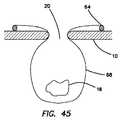
図44および図45は、テザー22および開口部20のところに位置した可撓性リング64を有する袋18を示している。袋材料は、透明であっても良く、あるいは不透明であっても良く、リング64は、小さな切開創を通って挿入できるよう圧縮可能である。側壁68を第1のリング64に巻き付けると、袋の高さを減少させることができ、従って検体を開口部の近くに持ち上げることができ、それにより検体を細切のために接近可能にすることができる。 44 and 45 show abag 18 with aflexible ring 64 located at thetether 22 andopening 20. The bag material may be transparent or opaque, and thering 64 is compressible for insertion through a small incision. Wrapping theside wall 68 around thefirst ring 64 can reduce the height of the bag, thus allowing the specimen to be lifted near the opening, thereby making the specimen accessible for shredding. Can be done.

図46および図47は、図47の袋18のための袋配備または展開器械124を示している。器械124は、トロカールを通って挿入可能である。袋18は、開口部20、テザー22および配備キャップ21を有している。 46 and 47 show the bag deploying or deployinginstrument 124 for thebag 18 of FIG. 47. Theinstrument 124 can be inserted through the trocar. Thebag 18 has anopening 20, atether 22, and adeployment cap 21.

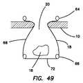
図48および図49は、第1のリング64、第2のリング66、第1のリングと第2のリングとの間の側壁68および基部72を有する別の袋変形例を示している。袋18の底部のところに配置された弾性の第2のリング66により、袋は、体腔12内に配置されると、ラッパ状に広がって開き、また、かかる弾性の第2のリングは、物体が検体16にくっつくのを阻止するのを助ける。検体を袋18内に入れた後、第1のリング64を図49に示されているように腹壁10の表面まで引く。 48 and 49 show another bag variant having afirst ring 64, asecond ring 66, aside wall 68 between the first ring and the second ring, and abase 72. An elasticsecond ring 66 located at the bottom of thebag 18 causes the bag to spread and open like a trumpet when placed in thebody cavity 12, and such an elastic second ring is an object. Helps prevent thesample 16 from sticking. After the sample is placed in thebag 18, thefirst ring 64 is pulled to the surface of theabdominal wall 10 as shown in FIG.

図50は、小さな切開創を通って容易な挿入を可能にする一方で袋18を腹腔12内で開き状態に保つ支持作用を提供するニチノール製の第1のリング64を有する袋18を示している。 FIG. 50 shows abag 18 with afirst ring 64 made of nitinol that provides a supportive action that keeps thebag 18 open within theabdominal cavity 12 while allowing easy insertion through a small incision. There is.

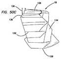
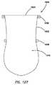
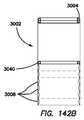
図50A〜図50Dは、種々の実施形態による袋18を非潰れ状態または拡張もしくは部分拡張状態で示している。図示のように、袋18は、閉鎖端部126および少なくとも1つの開放端部128を有する。開放端部128は、種々の実施形態によれば、袋18の開放端部128を包囲するテザーまたは引きひも130を有する。テザー130を操作することにより袋18の開放端部128が閉じられる。図示の袋18は、袋18の閉鎖端部126と開放端部128との間で袋18の壁134に設けられた複数の予備成形折り目132または既定の変形パターンを有する。種々の実施形態による袋18は、袋18が潰れるとともに扁平な状態になる傾向を提供するよう形成され、このような潰れるとともに扁平になった状態では、開放端部128が上方に向きまたは体腔の開口部の方へ向くとともに最大幅、最大直径または最大開口部寸法を有しかつ閉鎖端部126が体腔の開口部から遠ざかる方向に向くとともに体腔に沿って扁平かつ安定した状態になるよう構成された状態で最小高さが提供される。種々の実施形態によれば、力が一方向に加えられると、袋18の壁134の高さは、袋18内の検体を捕捉しまたは包囲するよう増大する。折り目132または変形パターンは、袋18のかかる高さの増大が力を加えている方向に比例して起こるようにする。種々の実施形態によれば、重量、検体または逆の力が袋18に加えられて袋18の高さの増大、または特に袋18の比例的な高さの増大を更に助ける。 50A-50D show thebags 18 according to various embodiments in a non-crushed or expanded or partially expanded state. As shown, thebag 18 has aclosed end 126 and at least oneopen end 128. Theopen end 128 has a tether ordrawstring 130 that surrounds theopen end 128 of thebag 18, according to various embodiments. By operating thetether 130, theopen end 128 of thebag 18 is closed. The illustratedbag 18 has a plurality of preformedfolds 132 or predetermined deformation patterns provided on thewall 134 of thebag 18 between theclosed end 126 and theopen end 128 of thebag 18.Bags 18 according to various embodiments are formed to provide a tendency for thebag 18 to collapse and become flat, with theopen end 128 pointing upwards or in the body cavity in such a collapsed and flattened state. It is configured to have a maximum width, maximum diameter or maximum opening size as it faces the opening and theclosed end 126 points away from the opening of the body cavity and remains flat and stable along the body cavity. The minimum height is provided in the open state. According to various embodiments, when a force is applied in one direction, the height of thewall 134 of thebag 18 increases to capture or surround the specimen in thebag 18. Thecrease 132 or deformation pattern allows the increase in applied height of thebag 18 to occur in proportion to the direction in which the force is applied. According to various embodiments, weight, specimen or vice versa is applied to thebag 18 to further aid in increasing the height of thebag 18, or in particular the proportional height increase of thebag 18.

一実施形態では、袋18は、患者の体内への配備に先立って、折り畳まれて扁平に成りまたはアコーディオン状態にされる。袋18は、配備時に、袋18の開放端部128が頂部上に位置するとともに閉鎖端部126が底部上に位置した状態で扁平な状態になる。閉鎖端部126は、例えば、患者の体腔内で底部上に位置する。したがって、袋18の開放端部128は、袋18の壁134上に形成されたパターンにより、開放状態のままであり、かくして、開放状態に保持される必要はない。加うるに、パターンにより、開放端部128は、開放状態に付勢されて閉鎖に抵抗する。検体を袋上および/または袋内に配置する上での困難さおよび時間がそれにより軽減される。 In one embodiment, thebag 18 is folded into a flattened or accordion state prior to deployment into the patient's body. At the time of deployment, thebag 18 is in a flat state with theopen end 128 of thebag 18 located on the top and theclosed end 126 located on the bottom. Theclosed end 126 is located, for example, in the patient's body cavity on the bottom. Therefore, theopen end 128 of thebag 18 remains in the open state due to the pattern formed on thewall 134 of thebag 18 and thus does not need to be held in the open state. In addition, the pattern causes theopen end 128 to be urged into an open state to resist closure. This alleviates the difficulty and time of placing the specimen on and / or in the bag.

外科医は、検体を袋18の開放端部128上でまたはこれを覆って袋18の頂部上に載せる。テザー130を引くことによって、袋18の壁134が引き上げられるとともに検体の周りに引き寄せられ、それにより検体を収容する。テザー130に加わる互いに逆の引き力および袋18に加わる検体の重量により、袋18の壁134に沿う変形パターンが広がりまたは真っ直ぐになる。一実施形態では、袋18の底部または閉鎖端部126は、テザー130が引かれているときに袋18の壁134を真っ直ぐにするのに十分な逆向きの力が提供されるようにするために重りまたは取り付け可能な重りを有する。一実施形態では、袋18を引き出しまたは体腔内の開口部に向かって引く力によっても袋18の壁134または壁134の1つまたは2つ以上の折り目132が広がるようにするために、1つまたは2つ以上のタブ136または袋18の開放端部128周りの袋18の幾つかの部分が提供される。 The surgeon places the specimen on or over theopen end 128 of thebag 18 on top of thebag 18. By pulling thetether 130, thewall 134 of thebag 18 is pulled up and pulled around the specimen, thereby accommodating the specimen. The opposite pulling forces applied to thetether 130 and the weight of the specimen applied to thebag 18 widen or straighten the deformation pattern along thewall 134 of thebag 18. In one embodiment, the bottom orclosed end 126 of thebag 18 is to provide sufficient reverse force to straighten thewall 134 of thebag 18 when thetether 130 is being pulled. Has a weight or a weight that can be attached to the bag. In one embodiment, one so that the force of pulling thebag 18 out or pulling it towards an opening in the body cavity also causes one ormore folds 132 of thewall 134 orwall 134 of thebag 18 to widen. Alternatively, two ormore tabs 136 or some portion of thebag 18 around theopen end 128 of thebag 18 is provided.

一実施形態では、検体の重量により袋18が引き下げられると、これにより、袋18の短い方の側部が下方に引かれて全体的な収容サイズを減少させる。種々の実施形態によれば、全体的収容サイズの減少分を補償しまたは減少させるため、袋18の扁平な側部上に位置して袋18がその全体的収容サイズを減少させるのを阻止する1つまたは2つ以上のタブ136が袋18の開口端部128のところに設けられる。したがって、一実施形態では、袋18を平べったくすると、袋18の縁に沿う距離は、袋18の断面に沿う距離よりも長い。テザー130は、一実施形態では、タブ136中に通される。 In one embodiment, when thebag 18 is pulled down by the weight of the specimen, this pulls the shorter side of thebag 18 downwards, reducing the overall containment size. According to various embodiments, it is located on the flat side of thebag 18 to prevent thebag 18 from reducing its overall storage size in order to compensate for or reduce the reduction in overall storage size. One ormore tabs 136 are provided at theopen end 128 of thebag 18. Therefore, in one embodiment, when thebag 18 is flattened, the distance along the edge of thebag 18 is longer than the distance along the cross section of thebag 18. Thetether 130 is threaded throughtab 136 in one embodiment.

袋18の特定の所望の高さおよび/または幅の場合、図50Eおよび図50Fに示されているパターンは、適正な配備および操作(例えば、真っ直ぐにすることおよび収容すること)を保証する壁パターンを最適に形成するために用いられる。一実施形態では、袋18は、図示のパターン付きで予備成形され、袋18は、次に、平べったくかつパターン付けされた状態を維持するよう加熱される。テザー130が袋18の開放端部128のところでタブ136を通って取り付けられまたは通される。したがって、袋18を当初の平べったい、安定化されかつパターン付けされた状態にするための熱、圧力または予備成形条件は、変形パターンを保つのを助け、それにより、体腔内に配置されると、袋18が潰れかつ変形状態になりまたは付勢される。袋18の中心部に加えられる下向きの力は、折り目132が真っ直ぐになりまたは広がり、それにより検体を包み込むよう袋18を拡張しまたは長くしてその高さを増大させるのを助ける。図示のように、パターンの谷部および/または山部は、直線的かつ一定の、または測定されたサイズの増大を一段と保証するよう同一の高さおよび/または幅を有するのが良い。種々の実施形態では、パターンの谷部または山部は、互いに異なる寸法を有しても良く、しかも円筒形の配備器具の内壁に等しい力を加えるのが良く、それにより袋18を配備するのに必要な力を小さくする。 For the particular desired height and / or width of thebag 18, the patterns shown in FIGS. 50E and 50F are walls that ensure proper deployment and operation (eg, straightening and containment). It is used to optimally form the pattern. In one embodiment, thebag 18 is premolded with the pattern shown and thebag 18 is then heated to remain flat and patterned. Atether 130 is attached or threaded throughtab 136 at theopen end 128 of thebag 18. Therefore, the heat, pressure or pre-molding conditions to bring thebag 18 to its original flat, stabilized and patterned state help maintain the deformation pattern, thereby placing it in the body cavity. Then, thebag 18 is crushed and deformed or urged. The downward force applied to the center of thebag 18 helps thecrease 132 straighten or widen, thereby expanding or lengthening thebag 18 to wrap the specimen and increasing its height. As shown, the valleys and / or peaks of the pattern should have the same height and / or width to further ensure a linear and constant, or measured increase in size. In various embodiments, the valleys or peaks of the pattern may have different dimensions and may apply equal force to the inner wall of the cylindrical deploying device, thereby deploying thebag 18. Reduce the force required for.

種々の実施形態によれば、袋の頂端部または開放端部および底端部または閉鎖端部は、交互の方向にねじられ、それにより袋の壁上に渦巻きパターンが形成される。袋および/または渦巻き体は、加熱されまたは圧縮されてこれらの形状を保つ。螺旋折り目は、体内に挿入された後、袋を平べったい状態に保つのを助ける。検体を袋の開放端部上に載せた後、袋の開放端部を包囲しているテザーを引くと、袋の壁が広がりまたはねじりを解く。したがって、テザーまたは袋の開放端部に加わる互いに逆向きの引く力および検体の重量および/または袋の閉鎖端部または底部のところの取り付け状態のまたは追加された重量により、袋は、袋が体腔の開口部に向かって引き寄せられているときにねじりを解いて検体を包み込む。種々の実施形態によれば、開放端部は、第1のリングを有するとともに/あるいは閉鎖端部は、第2のリングを有する。第1および/または第2のリングは、開放端部を開放または拡張状態に付勢して検体を受け入れ、袋が平べったいまたは非拡張状態のままであるようにする傾向を高め、あるいは袋の拡張を助けるための重量を提供しあるいは袋の配置または検体の受け入れおよび捕捉の安定性を提供するよう、ワイヤもしくはロッドで補強されまたはワイヤもしくはロッドを有するのが良い。 According to various embodiments, the top or open end and bottom or closed end of the bag are twisted in alternating directions, thereby forming a swirl pattern on the wall of the bag. The bag and / or swirl is heated or compressed to retain these shapes. The spiral crease helps keep the bag flat after being inserted into the body. After placing the specimen on the open end of the bag, pulling the tether surrounding the open end of the bag widens or untwists the wall of the bag. Thus, due to the opposite pulling forces exerted on the tether or the open end of the bag and the weight of the specimen and / or the attached or additional weight at the closed end or bottom of the bag, the bag is cavityd. Untwist and wrap the specimen as it is pulled towards the opening of the. According to various embodiments, the open end has a first ring and / or the closed end has a second ring. The first and / or second ring urges the open end to open or expand to accept the specimen, increasing the tendency to leave the bag flat or unexpanded, or It may be reinforced with wires or rods or have wires or rods to provide weight to aid bag expansion or to provide bag placement or specimen acceptance and capture stability.

種々の実施形態によれば、袋の頂部または開放端部および底部または閉鎖端部は、互いに向かって直接潰される。袋の開放端部と閉鎖端部との間における袋の壁の皺または折り目は、加熱されまたは圧縮されてこれらのパターン/形状を保つとともに体内に挿入された後に袋を平べったい状態に保つのを助ける。検体を袋の開放端部上に載せた後、袋の開放端部を包囲しているテザーを引くと、袋の壁の皺が伸びまたは袋の壁が真っ直ぐになる。したがって、テザーまたは袋の開放端部に加わる互いに逆向きの引く力および検体の重量および/または袋の閉鎖端部または底部のところの取り付け状態のまたは追加された重量により、袋は、袋が体腔の開口部に向かって引き寄せられているときに真っ直ぐになって検体を包み込む。種々の実施形態によれば、開放端部は、第1のリングを有するとともに/あるいは閉鎖端部は、第2のリングを有する。第1および/または第2のリングは、開放端部を開放または拡張状態に付勢して検体を受け入れ、袋が平べったいまたは非拡張状態のままであるようにする傾向を高め、あるいは袋の拡張を助けるための重量を提供しあるいは袋の配置または検体の受け入れおよび捕捉の安定性を提供するよう、ワイヤもしくはロッドで補強されまたはワイヤもしくはロッドを有するのが良い。 According to various embodiments, the top or open end and bottom or closed end of the bag are crushed directly towards each other. Wrinkles or creases in the wall of the bag between the open and closed ends of the bag are heated or compressed to retain these patterns / shapes and to flatten the bag after being inserted into the body. Help keep. After placing the specimen on the open end of the bag, pulling the tether surrounding the open end of the bag will stretch the wrinkles on the wall of the bag or straighten the wall of the bag. Therefore, due to the opposite pulling forces exerted on the tether or the open end of the bag and the weight of the specimen and / or the attached or added weight at the closed end or bottom of the bag, the bag is cavityd. Straighten and wrap the specimen as it is pulled towards the opening of the. According to various embodiments, the open end has a first ring and / or the closed end has a second ring. The first and / or second ring urges the open end to open or expand to accept the specimen, increasing the tendency to leave the bag flat or unexpanded, or It may be reinforced with wires or rods or have wires or rods to provide weight to aid bag expansion or to provide bag placement or specimen acceptance and capture stability.

図50Gおよび図50Hに示されているように、袋18は、立方体、プリズム、円柱、球体、十二面体、半球形、円錐体、直方体、多面体等を含む(これらには限定されない)種々の上側、基部および全体的形状を有するのが良く、この袋は、1つまたは2つ以上の開口部を備えるとともに袋が潰れたまたは実質的に平べったい形状のままである傾向を示すとともに検体を収容して包み込むよう操作されると直線状または制御された状態で拡張するよう種々の変形壁パターンを備える。 As shown in FIGS. 50G and 50H, thebag 18 includes, but is not limited to, cubes, prisms, cylinders, spheres, dodecahedrons, hemispheres, cones, rectangular parallelepipeds, polyhedra, and the like. It should have an upper, base and overall shape, with the bag having one or more openings and showing a tendency for the bag to remain crushed or substantially flat in shape. It is provided with various deformed wall patterns to expand linearly or in a controlled manner when manipulated to contain and wrap the specimen.

細切システム中に含まれるべきまたは一体化されるべき接近システムの種々の実施例であって、接近システム全体、接近システムの幾つかの部分または接近システムおよび/またはそのコンポーネントの組み合わせが本発明の種々の実施形態に従ってチャネルおよび/またはほぼ領域を提供するよう配置されている種々の実施例が2013年4月18日に出願された米国特許出願第13/865,854号明細書、2013年9月20日に出願された同第61/880,641号明細書、2009年10月13日に出願された同第12/578,422号明細書、2008年10月13日に出願された同第61/104,963号明細書、2009年1月22日に出願された同第12/358,080号明細書、2006年3月13日に出願された同第11/374,188号明細書、2007年3月8日に出願された同第11/683,821号明細書、2009年3月3日に出願された同第12/396,624号明細書、2014年3月13日に出願された同第14/209,161号明細書、2010年8月31日に出願された同第12/873,115号明細書、2010年7月21日に出願された同第12/840,989号明細書、2006年10月12日に出願された同第11/548,758号明細書、2004年11月30日に出願された同第10/516,198号明細書、および2003年9月17日に出願された同第10/666,579号明細書に記載されており、これら米国特許出願を参照により引用し、これらの記載内容があたかも本明細書に記載されているかのごとくこれらの開示内容を本明細書の一部とする。 Various embodiments of the approach system to be included or integrated in the shredded system, wherein the entire approach system, some parts of the approach system or a combination of the approach system and / or its components U.S. Patent Application No. 13 / 856,854, 2013: 9 in which various examples arranged to provide channels and / or substantially areas according to various embodiments were filed on April 18, 2013. The same specification No. 61 / 880,641 filed on the 20th of March, the same specification No. 12 / 578,422 filed on October 13, 2009, and the same filed on October 13, 2008. No. 61 / 104,963, No. 12 / 358,080 filed on January 22, 2009, No. 11 / 374,188 filed on March 13, 2006. No. 11 / 683,821, filed March 8, 2007, No. 12 / 396,624, filed March 3, 2009, March 13, 2014. No. 14 / 209,161 filed in, No. 12 / 873,115 filed on August 31, 2010, No. 12 / filed on July 21, 2010. 840,989, 11 / 548,758, filed October 12, 2006, 10 / 516,198, filed November 30, 2004, and It is described in the same specification No. 10 / 666,579 filed on September 17, 2003, and these US patent applications are cited by reference, and whether these descriptions are described in the present specification. As described above, the contents of these disclosures are a part of the present specification.

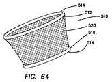
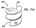
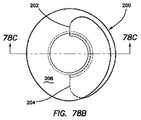
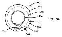
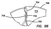
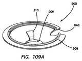
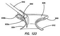
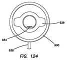
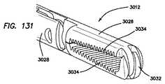
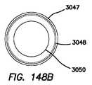
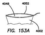
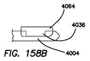
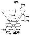
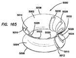
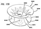
次に図51〜図53を参照すると、本発明のガードまたはシールド200の別の変形例が示されている。ガード200は、全体として渦巻きの形をしている。ガード200は、第1の内側端部202および第2の外側端部204を有する。第1の端部202と第2の端部204は、リーフまたはバンドとも呼ばれる中央部分206によって互いに連結されている。ガード200は、後続端部または近位端部とも呼ばれる頂端部212、先導端部または遠位端部とも呼ばれる底端部214ならびに第1の内側端部202および第2の外側端部204によって互いに連結された内面208と外面210を有する。中央部分206またはバンドは、凹状の外面210を有し、内面208は、渦巻きの内部から見て凸状である同形面を形成する。バンドの陥凹は、一変形例では放物線であり、変曲点は、頂端部212と底端部214との中間に位置し、ただし本発明は、これには限定されず、変曲点は、頂端部212と底端部214との間のどこかの場所に位置していても良く、それどころか頂端部212または底端部214と一致しまたはほぼ一致していても良い。バンド206は、陥凹を備えなくても良く、バンド206は、頂端部212と底端部214との間でガード200の少なくとも一部分に沿って単に湾曲していても良くあるいは真っ直ぐであっても良い。ガード200は、底端部と同一の外径を有する頂端部を有するものとして対称であるものとして示されている。別の変形例では、ガード200は、形状が非対称であり、このガードは、底端部に対して直径が大きいまたは小さい頂端部を有しても良い。ガード200はまた、垂直方向に対称であるが、本発明はこれには限定されず、ガード200は、基準水平面に対して角度をなしている中心軸線を有しても良い。ガード200は、バンドの一部分が湾曲し、円形のまたは楕円形の状態でバンドの別の部分とオーバーラップするよう渦巻き形状を有する。具体的に言えば、バンド200の外面210の少なくとも一部分は、バンド200の内面の少なくとも一部分とオーバーラップするとともにこれに向いていて、バンド200の一部の陥凹がバンドの別の部分の陥凹に隣接して位置しまたは並置し、バンドの一部分をバンドの他の部分内に嵌入して嵌め込んでいる。渦巻き体は、円周方向長さが約3πRである1回と半分のターンを有する休止しかつ機械的にストレスの受けていない形態を有するものとして示されており、この場合Rは、ガード200の長手方向軸線に垂直にとった半径である。本発明は、正確に1.5のターンを有するガードには限定されず、特定の切開創サイズについてその寸法、形状および所望の力分布状態ならびに機能、例えばレトラクタ機能および/または保持機能に従って所望通りにこれよりも多いまたは少ないターンを有しても良い。渦巻き状ガード200の特定の利点は、その形状および寸法を変更することができ、拡大することができまたは縮小することができるということにある。本質的には、バンドは、それ自体に対して滑ることができ、それにより大きな直径を有する大径の渦巻き形態または小さい直径を有する小径の渦巻き形態を形成することができる。渦巻き状ガード200は、渦巻き体によって形成された中央ルーメン216を有し、渦巻き体を拡張しまたは開くと、この渦巻き体を拡大することもできる。中央ルーメン216の寸法もまた、渦巻き体を閉じまたはバンドをそれ自体多数のターンを生じさせる緊密なカールの状態にまたはこれに対して少数のターンを有する大きな直径を生じさせる大きなカールの状態に滑らせることによって螺旋の寸法を減少させると縮小可能である。中央ルーメン216は、実質的に形状が円形であるが、本発明は、これには限定されず、中央ルーメン216は、形状が楕円形であっても良くまたは不定であっても良い。したがって、渦巻き状シールド200は、患者の創部もしくは切開創または上述した患者の体内に配置された袋中に他のガードとともに挿入されると、調節可能である。切開創の寸法に応じて、渦巻き形状を開きまたは閉じることによって渦巻き状シールド200を、大きくまたは小さく調節することができ、ガードをそれ自体カールさせることにより多くのターンを形成し、それにより創部開口部または袋にそれに応じて適合させることができる。さらに、渦巻き状シールド200を特定の休止または通常の直径方向位置、形状および寸法に関して所定のバイアスを備えた状態で成形できる。例えば、約1インチ(2.54cm)の切開創が患者に作られる場合、約2インチ(5.08cm)の休止直径を有する渦巻き状シールド200の寸法は、渦巻き状シールド200をそれ自体ねじってその巻き数をそれ自体増大させ、それによりその直径を減少させることによって減少可能である。縮小形態にある間、渦巻き状シールド200を1インチ(2.54cm)の切開創中に挿入し、次に放出する。これに対して、バイアスが渦巻き状シールド200中に成形されているので、渦巻き状シールド200は、その通常の形態に向かう傾向があり、従ってその縮小形態から拡張し、有利には、切開創をレトラクトすると同時に渦巻き状シールド200を保持している切開創およびシールド200と切開創との間に位置するどんなものでも、例えば、患者に対して定位置にある袋に密着しまたは押し当たる。変形例として、シールド200は、有利には、切開創中に挿入されると、組織の力を受けて縮小可能である。シールドに対する組織の力は、シールドの直径方向寸法を減少させることができる。シールドが調節可能なので、大きな検体の取り出しのために渦巻き体を開くことによって中央開口部またはルーメン216の寸法を増大させることができる。この調節性により、有利には、周囲の組織に加わるひずみが減少し、切開創部位ができるだけ小さく保たれ、感染の恐れが減少し、それと同時に、検体を体から引き出すために必要に応じて渦巻き体を開くことによって切開創寸法を小さくしたり大きくしたりすることができる。場合によっては、取り出されるべき組織の寸法は、予測不能であり、この調節性により、有利には、医師にとって困難を生じさせることなく広汎な組織検体の取り出しを容易にすることができる。 Next, referring to FIGS. 51 to 53, another modification of the guard or shield 200 of the present invention is shown. Theguard 200 has a spiral shape as a whole. Theguard 200 has a firstinner end 202 and a secondouter end 204. Thefirst end 202 and thesecond end 204 are connected to each other by acentral portion 206, also called a leaf or band. Theguards 200 are connected to each other by atop end 212, also called a trailing end or a proximal end, abottom end 214, also called a leading end or a distal end, and a firstinner end 202 and a secondouter end 204. It has aninner surface 208 and anouter surface 210 that are connected. Thecentral portion 206 or the band has a concaveouter surface 210, theinner surface 208 forming an isomorphic surface that is convex when viewed from the inside of the spiral. The recess of the band is a parabola in one variant, and the inflection point is located between thetop end 212 and thebottom end 214, but the present invention is not limited to this, and the inflection point is , It may be located somewhere between the apex 212 and the bottom 214, and on the contrary, it may coincide with or nearly coincide with the apex 212 or the bottom 214. Theband 206 does not have to be recessed, and theband 206 may simply be curved or straight along at least a portion of theguard 200 between the apex 212 and the bottom 214. good. Theguard 200 is shown as symmetrical as having a top end having the same outer diameter as the bottom end. In another variant, theguard 200 is asymmetric in shape and the guard may have a top end that is larger or smaller in diameter with respect to the bottom end. Theguard 200 is also vertically symmetrical, but the present invention is not limited thereto, and theguard 200 may have a central axis angled with respect to a reference horizontal plane. Theguard 200 has a spiral shape such that one part of the band is curved and overlaps another part of the band in a circular or oval state. Specifically, at least a portion of theouter surface 210 of theband 200 overlaps and faces at least a portion of the inner surface of theband 200, with one recess in theband 200 being recessed in another portion of the band. It is located adjacent to or juxtaposed to the recess and fits one part of the band into the other part of the band. The spiral body is shown to have a dormant and mechanically unstressed form with one and half turns having a circumferential length of about 3πR, where R is theguard 200. The radius taken perpendicular to the longitudinal axis of. The present invention is not limited to guards having exactly 1.5 turns, as desired according to their dimensions, shape and desired force distribution and function, such as retractor function and / or retention function, for a particular incision size. May have more or less turns. A particular advantage of thespiral guard 200 is that its shape and dimensions can be modified and can be expanded or contracted. In essence, the band can slide relative to itself, thereby forming a large diameter swirl form with a large diameter or a small diameter swirl form with a small diameter. Thespiral guard 200 has acentral lumen 216 formed by the spiral body, and the spiral body can be expanded by expanding or opening the spiral body. The dimensions of thecentral lumen 216 also slide the spiral body into a tight curl state that closes the spiral body or causes the band itself to produce many turns, or to a large curl state that produces a large diameter with a small number of turns. It can be reduced by reducing the size of the spiral by making it. Thecentral lumen 216 is substantially circular in shape, but the present invention is not limited thereto, and thecentral lumen 216 may be elliptical or indefinite in shape. Thus, thespiral shield 200 is adjustable when inserted with other guards into the patient's wound or incision or a bag placed within the patient's body as described above. Depending on the size of the incision, thespiral shield 200 can be adjusted larger or smaller by opening or closing the spiral shape, forming more turns by curling the guard itself, thereby forming the wound opening. It can be adapted to the part or bag accordingly. In addition, thespiral shield 200 can be formed with a particular rest or a given bias with respect to normal diametrical position, shape and dimensions. For example, if an incision of about 1 inch (2.54 cm) is made in the patient, the dimensions of thespiral shield 200 with a dormant diameter of about 2 inches (5.08 cm) twist thespiral shield 200 itself. It can be reduced by increasing its number of turns itself and thereby reducing its diameter. While in the reduced form, thespiral shield 200 is inserted into a 1 inch (2.54 cm) incision and then released. On the other hand, since the bias is formed in thespiral shield 200, thespiral shield 200 tends towards its normal form, thus extending from its reduced form and advantageously making an incision. Any incision that retracts and holds thespiral shield 200 and anything that is located between theshield 200 and the incision is, for example, in close contact with or against a bag that is in place with respect to the patient. As a variant, theshield 200 can advantageously shrink under the force of tissue when inserted during an incision. The force of the tissue on the shield can reduce the radial dimension of the shield. Since the shield is adjustable, the size of the central opening orlumen 216 can be increased by opening the swirl for removal of large specimens. This controllability advantageously reduces the strain applied to the surrounding tissue, keeps the incision site as small as possible, reduces the risk of infection, and at the same time swirls as needed to withdraw the specimen from the body. The incision size can be reduced or increased by opening the body. In some cases, the size of the tissue to be removed is unpredictable, and this controllability can advantageously facilitate the removal of a wide range of tissue specimens without causing difficulty for the physician.

渦巻き状シールド200の位置は、バンドの曲率または陥凹の助けにより切開創部位または生まれつきの体口、例えば膣に対して保持されるので更に有利である。具体的に言えば、頂端部212は、頂部フランジとも呼ばれる頂部リップを形成し、この頂部リップは、少なくとも一部が組織の上面上に円周方向に延びている。底端部214は、底部リップまたは底部フランジを形成し、この底部リップは、少なくとも一部は、患者の体腔内の組織の上面、腹壁または手術用作業空間上に円周方向に延び、有利には、組織をレトラクトしてこれを一般にバンドの内面208であるシールド200の切断面から遠ざける。組織は、バンドの外面210に当てて受け入れられ、この組織は、外面210の陥凹または湾曲形状内に嵌め込まれ、それによりシールドおよび収容袋を定位置に保ち、フランジは、シールドが滑り落ちて患者の体内に入りまたは滑り上がって患者の体外に出るのを阻止する。当然のことながら、シールド200は、外科用切開創/体口内にまたは収容袋および上述の創部レトラクタのうちの任意の1つまたは2つ以上内に直接配置される。細切は、外科医によって選ばれた任意の技術または方式で進めることができ、かかる技術または方式としては、シールド200の内面208を切断板として用いることが挙げられ、ブレードが把持器により中央ルーメン216を通ってまたはこの中に引っ込められた組織をこの切断板に当てた状態で切断するために使用されるのが良い。細切されるべき組織を中央ルーメン216に通して引き上げると、この組織をガード200の内面208に当てて位置決めすることができ、ブレードまたは小刀を用いて組織をシールド200に当てた状態で切断することができる。シールド200は、適当な材料、例えば任意のポリマーまたは金属で作られている。適当な一材料は、超高分子量ポリエチレンプラスチックである。別の適当な材料は、低線密度ポリエチレンである。シールド材料は、組織がシールド材料に当てた状態で切断されたときに容易には穴あけされずまたは容易には切断されずに組織を保護するのに最適化された厚さを有する。細切が完了すると、シールドをそれ自体巻いて手術部位からの容易な取り出しが可能な縮小形態にすることによって渦巻き状シールド200の直径を減少させるのが良い。変形例として、シールド200を垂直方向にまたはシールドの長手方向軸線に沿って引くことによってシールド200を取り出しても良い。 The position of thespiral shield 200 is even more advantageous as it is held against the incision site or the natural ostium, such as the vagina, with the help of the curvature or depression of the band. Specifically, the apex 212 forms a crest lip, also called a crest flange, which at least part extends circumferentially over the top surface of the tissue. Thebottom end 214 forms a bottom lip or bottom flange, which, at least in part, extends circumferentially over the top surface, abdominal wall, or surgical workspace of tissue within the patient's body cavity, advantageously. Retracts the tissue and keeps it away from the cut surface of theshield 200, which is generally theinner surface 208 of the band. The tissue is received against theouter surface 210 of the band, which is fitted into the recessed or curved shape of theouter surface 210, thereby keeping the shield and containment bag in place and the flange where the shield slides off. Prevents it from entering or slipping into the patient's body and out of the patient's body. Of course, theshield 200 is placed directly in the surgical incision / body mouth or in any one or more of the containment bag and the wound retractor described above. Shredding can be carried out by any technique or method chosen by the surgeon, such technique or method including the use of theinner surface 208 of theshield 200 as a cutting plate, with the blade having acentral lumen 216 by a gripper. It is best used to cut tissue that has been retracted through or into it in contact with this cutting plate. When the tissue to be shredded is pulled up through thecentral lumen 216, this tissue can be positioned against theinner surface 208 of theguard 200 and cut with a blade or knife against theshield 200. be able to. Theshield 200 is made of a suitable material, for example any polymer or metal. A suitable material is ultra high molecular weight polyethylene plastic. Another suitable material is low linear density polyethylene. The shield material has a thickness optimized to protect the tissue without being easily perforated or easily cut when the tissue is cut in contact with the shield material. When the shredding is complete, it is preferable to reduce the diameter of thespiral shield 200 by winding the shield itself into a reduced form that allows easy removal from the surgical site. As a modification, theshield 200 may be removed by pulling theshield 200 vertically or along the longitudinal axis of the shield.

図52および図53は、螺旋の形をした成形モールド220のコアピン状の渦巻き状シールド200を示している。渦巻き状シールド200を射出成形によって製造するため、シールド200を螺旋モールド220上に成形する。モールド220のコアピンをいったん巻き戻すと、一端部を隣接の巻線の前または後ろに押し込むことによってシールド200をその機能発揮渦巻き形態にすることができる。シールド200は、当初螺旋状に形成され、次に、渦巻き状にされるので、シールド200は、その中に幾分かのスプリングバック張力記憶作用を有し、それにより、シールド200は、完全な渦巻き状のままでいることなく、螺旋形状を取ろうとする。シールド200が望ましくなくかつ過剰の量のスプリングバイアス張力を有する場合、シールド200を適当な温度で割り当てられた時間をかけてオーブン内に配置することによってアニーリングプロセスを実施するのが良く、次にこれを取り出し、それによりシールド200内の残留張力を減少させまたはなくす。しかしながら、シールド200の一変形例では、幾分かの残りの張力が有利には望ましく、その理由は、シールド200が長手方向軸線に沿って拡張する傾向により切開創部位からの器具の取り出しが容易になるからである。タブ(図示せず)がシールド200の一端部、例えば近位端部、内側端部または外側端部上に形成されるのが良くかつ/あるいは穴がシールドの一端部の近くに形成されるのが良く、引きひもをこの穴に通して取り付けることができ、その結果、医師がこのひもまたはタブを引いてシールド200を切開創部位から容易に取り出すことができる。タブまたは穴は、シールドを挿入する上での方向上の優先度を指示することができ、その結果、タブ/穴が患者の体外で外科医の近くに位置した状態で器具を取り出す際に螺旋張力を利用することができるようになっている。一変形例では、巻線の内側に同形化される第1の内側端部202にはこの取り出し特徴のためにタブが設けられまたは穴が設けられる。取り出し中、内側端部202を垂直方向に引くと、シールドのバンドは、次第に伸びて切開創部位から出る。 52 and 53 show a core pin-shapedspiral shield 200 of a spiral-shapedmolding mold 220. In order to manufacture thespiral shield 200 by injection molding, theshield 200 is molded on thespiral mold 220. Once the core pin of themold 220 is rewound, theshield 200 can be made into its functional swirl form by pushing one end in front of or behind the adjacent winding. Since theshield 200 is initially spirally formed and then spiraled, theshield 200 has some springback tension storage effect therein, whereby theshield 200 is complete. Attempts to take a spiral shape without remaining spiral. If theshield 200 has an undesired and excessive amount of spring bias tension, it is better to carry out the annealing process by placing theshield 200 in the oven at a suitable temperature for an allotted time, then this. Is removed, thereby reducing or eliminating residual tension in theshield 200. However, in one variant of theshield 200, some remaining tension is preferably desirable, because theshield 200 tends to expand along the longitudinal axis, making it easier to remove the instrument from the incision site. Because it becomes. Tabs (not shown) are preferably formed on one end of theshield 200, such as the proximal, inner or outer ends, and / or holes are formed near one end of the shield. The drawstring can be attached through this hole so that the physician can easily pull the cord or tab to remove theshield 200 from the incision site. The tab or hole can indicate a directional priority in inserting the shield, resulting in spiral tension when removing the instrument with the tab / hole located outside the patient's body and close to the surgeon. Can be used. In one variant, the firstinner end 202, which is homomorphized inside the winding, is tabbed or perforated for this retrieval feature. As themedial end 202 is pulled vertically during removal, the band of the shield gradually extends out of the incision site.

射出成形の代替手段として、渦巻き状シールド200は、プラスチックシート素材から製造されても良く、ダイカットされても良く、所定形状に熱成形されても良い。また、シールド200を螺旋状に射出成形するのではなく、渦巻き状シールド200を螺旋体の形状に直接射出成形しても良い。 As an alternative to injection molding, thespiral shield 200 may be manufactured from a plastic sheet material, die-cut, or thermoformed into a predetermined shape. Further, instead of injection molding theshield 200 in a spiral shape, thespiral shield 200 may be directly injection molded into the shape of a spiral body.

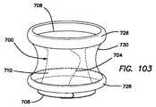
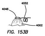
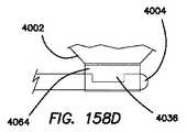
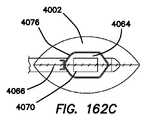
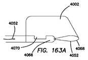
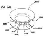
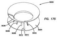
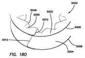
次に図71Aおよび図71Bを参照すると、シールド200がそれぞれ拡張された細長い形態および圧縮されまたは非拡張状態の形態で示されている。シールド200の拡張形態は、図72〜図74にも詳細に示されている。シールド200は、拡張形態では、内面208を外面210上にオーバーラップさせることによって圧縮形態に変換可能である。シールド200の圧縮形態が図76〜図79にも示されている。シールド200の少なくとも一部分は、図78A〜図78Cに明確に示されているように非拡張形態においてそれ自体オーバーラップしている。図78Cでは、シールド200の隣接のオーバーラップ部分の外面210の陥凹内へのシールド200の一部分の嵌合状態が示されている。シールド200は、少なくとも一部が長手方向軸線218周りに巻かれまたはカールされるようになっている。シールド200は、少なくとも一部が長手方向軸線218周りにそれ自体の上に巻かれまたはカールされるようになっており、その結果、シールド200の一部分は、シールド200の別の部分とオーバーラップしまたはこれと並置状態でまたはこれと接触関係をなして位置するようになっている。図71Bの非拡張形態にあるとき、シールド200は、非拡張形態が創部または体口中への挿入に適した減少直径または側方寸法を有する密なロールの状態に巻かれたコンパクトな形態に加えて、弛緩したまたは通常の側方形態を有する。シールド200は、弛緩したまたは通常の側方形態に向かうバイアスを有し、このシールドは、創部または体口中への挿入後にこのバイアスに向かう傾向があり、それによりシールド200がシールド200に用いられる材料および挿入状態のシールド200に応答して周囲の組織により及ぼされる力に応じて、拡張してコンパクトな形態から大きな形態になるときに幾分かのレトラクション力を組織に及ぼす。創部または体口がきつい場合、シールド200は、その減少側方挿入形態から拡張しなくても良く、あるいは、シールドがその通常の弛緩形態に向かう傾向があるので側方寸法だけが僅かに拡張しても良く、それにより僅かに巻き出、あるいは、シールド200は、その通常の弛緩形態に完全に拡張しても良い。 Next, with reference to FIGS. 71A and 71B, theshield 200 is shown in an expanded elongated form and in a compressed or unexpanded state, respectively. An extended form of theshield 200 is also shown in detail in FIGS. 72-74. In the expanded form, theshield 200 can be converted into a compressed form by overlapping theinner surface 208 on theouter surface 210. The compressed form of theshield 200 is also shown in FIGS. 76 to 79. At least a portion of theshield 200 overlaps itself in the non-expanded form, as clearly shown in FIGS. 78A-78C. FIG. 78C shows a state in which a part of theshield 200 is fitted into the recess of theouter surface 210 of the adjacent overlapping portion of theshield 200. Theshield 200 is adapted to be at least partially wound or curled around thelongitudinal axis 218. Theshield 200 is designed to be at least partially wound or curled over itself around thelongitudinal axis 218 so that one part of theshield 200 overlaps another part of theshield 200. Or, it is positioned in a juxtaposed state with this or in a contact relationship with this. When in the non-expanded form of FIG. 71B, theshield 200 is in addition to the compact form in which the non-expanded form is rolled into a dense roll with a reduced diameter or lateral dimension suitable for insertion into the wound or body mouth. Has a relaxed or normal lateral morphology. Theshield 200 has a bias towards a relaxed or normal lateral form, the shield tends towards this bias after insertion into the wound or body mouth, whereby theshield 200 is the material used for theshield 200. And, depending on the force exerted by the surrounding tissue in response to the insertedshield 200, it exerts some retraction force on the tissue as it expands from a compact form to a large form. If the wound or body mouth is tight, theshield 200 does not have to expand from its reduced lateral insertion form, or only the lateral dimensions expand slightly as the shield tends towards its normal relaxed form. It may be slightly unwound, or theshield 200 may be fully extended to its normal relaxed form.

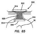
図71Aに示されているシールド200の垂直方向拡張形態は、シールド200が螺旋状モールド220上に成形された結果である。シールド200は、シールド200の中心が位置する長手方向軸線218を定める。シールド200は、少なくとも一部が垂直方向拡張位置に向かって付勢される材料で作られている。シールド200は、形状記憶材料で作られても良く、あるいは形状記憶材料で作られた部分を有しても良い。垂直方向圧縮形態にあるとき、垂直方向拡張形態へのバイアスの結果として、シールド200がばね作用で垂直方向拡張形態になることはなく、その理由は、外面の陥凹が頂部フランジ222とも呼ばれる頂部リップおよび底部フランジ224とも呼ばれる底部リップを形成するからであり、その結果、頂部フランジ222の少なくとも一部分は、圧縮形態にある間、隣接のオーバーラップ状態の頂部フランジ222に当接し、底部フランジ224の少なくとも一部分は、圧縮形態にある間、隣接のオーバーラップ状態の底部フランジ224に当接し、それにより、垂直方向圧縮形態が垂直方向拡張形態に容易にひょいと動くのが阻止される。頂部フランジ222および底部フランジ224のうちの少なくとも一方は、シールド200が拡張して圧縮形態から拡張形態になるのを阻止する停止部としての役目を果たす。拡張形態に向かうバイアスにより、幾分かの摩擦力が器具それ自体に及ぼされ、かかる摩擦力は、シールド200の側方寸法または直径方向拡張を調節するのを助ける。圧縮形態にあるとき、シールド200は、長手方向軸線回りに巻かれ/カールされるのが良く、それにより直径方向または側方寸法を減少させることができ、それによりシールド200の寸法を減少させるとともに中央ルーメン216の直径を減少させ、それにより小さな低侵襲性切開創または体口を通る挿入を容易にする。 The vertically expanded form of theshield 200 shown in FIG. 71A is the result of theshield 200 being molded onto thespiral mold 220. Theshield 200 defines alongitudinal axis 218 where the center of theshield 200 is located. Theshield 200 is made of a material that is at least partially urged towards the vertical extension position. Theshield 200 may be made of a shape memory material or may have a portion made of a shape memory material. When in the vertical compression form, theshield 200 does not spring into the vertical extension form as a result of the bias towards the vertical extension form, because the recess on the outer surface is also called thetop flange 222. This is because it forms a bottom lip, also called a lip and abottom flange 224, so that at least a portion of thetop flange 222 abuts on the adjacent overlappingtop flange 222 while in the compressed form of thebottom flange 224. At least a portion abuts on the adjacent overlappingbottom flanges 224 while in the compressed form, thereby preventing the vertical compressed form from easily moving into the vertical extended form. At least one of thetop flange 222 and thebottom flange 224 serves as a stop that prevents theshield 200 from expanding from the compressed form to the expanded form. The bias towards the expansion form exerts some frictional force on the instrument itself, which helps adjust the lateral dimension or diametrical expansion of theshield 200. When in the compressed form, theshield 200 is preferably wound / curled around the longitudinal axis, which can reduce the radial or lateral dimensions, thereby reducing the dimensions of theshield 200 as well as The diameter of thecentral lumen 216 is reduced, thereby facilitating small minimally invasive incisions or insertion through the body mouth.

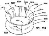
図80は、シールド200を周囲巻線の周長の約1.25倍を有する弛緩したまたは通常の側方形態で示しており、シールド内径またはルーメン内径226を備えた中央ルーメン216およびシールド直径228または外径を示しており、これらのうちのいずれかは、シールド200のための側方または直径方向寸法として役目を果たす。図81は、シールド200の平面図である。図81では、シールド200は、切開創/体口内への挿入に適したコンパクトな形態にあり、シールド200は、この切開創/体口を通って密なロールな状態にそれ自体巻かれる。図81のシールド200は、周囲巻線の周長の約2.25倍以上を有するとともに図80の弛緩した通常の形態に対して減少したルーメン直径226およびシールド直径228を有している。シールド200のオーバーラップ部分は、互いに接触しており、そして減少側方直径位置を僅かに摩擦の作用で保持するよう働いているが、側方寸法のバイアスが応力を受けていないまたは弛緩した半径方向通常形態に向かっているので、シールド200は、通常の形態になる傾向がある。減少側方寸法を備えたコンパクトな形態は、創部または体口中に適切に挿入されるようになっている。コンパクトな形態から、シールド200は、創部または体口の外部に位置したときに放出されると、拡張して減少側方寸法位置から通常の応力を受けていない側方寸法形態になる。現場でのこの拡張は、挿入状態のシールド200によって及ぼされる力に応答して組織によって及ぼされる力によって制限される場合がある。シールド200は、円形の形をしているとともに直径を有する中央ルーメン216を有しているが、本発明は、これらには限定されず、変形例は、幅よりも大きな長さを有する細長いルーメン216、例えば長円形または楕円形のルーメンを有するシールド200を含む。したがって、シールド200の外周は、対応の形状を有していても良く、あるいは有していなくても良い。シールド200の外周が中央ルーメン216の形状に一致した形状を有する変形例では、ルーメン216が円形である場合、シールド200の外周もまた円形であり、あるいは、中央ルーメン216が長円形または楕円形の形状を有している場合、シールドの外周もまた、長円形または楕円形の形状を有する。 FIG. 80 shows theshield 200 in a relaxed or normal lateral form with about 1.25 times the perimeter of the peripheral winding, with acentral lumen 216 and ashield diameter 228 with a shield inner diameter or lumeninner diameter 226. Alternatively, it indicates the outer diameter, and any of these serves as a lateral or radial dimension for theshield 200. FIG. 81 is a plan view of theshield 200. In FIG. 81, theshield 200 is in a compact form suitable for insertion into the incision / body opening, and theshield 200 is itself wound into a tight roll through the incision / body opening. Theshield 200 of FIG. 81 has a lumen diameter of 226 and a shield diameter of 228 that are more than about 2.25 times the perimeter of the peripheral winding and are reduced compared to the relaxed normal form of FIG. The overlapping portions of theshield 200 are in contact with each other and serve to hold the reduced lateral diameter position by the action of slight friction, but the lateral dimension bias is unstressed or relaxed radius. Direction Theshield 200 tends to be in the normal form as it is heading towards the normal form. The compact form with reduced lateral dimensions is designed to be properly inserted into the wound or body mouth. Due to its compact form, when released when located outside the wound or body mouth, theshield 200 expands into a lateral dimension form that is not normally stressed from the reduced lateral dimension position. This extension in the field may be limited by the force exerted by the tissue in response to the force exerted by the insertedshield 200. Theshield 200 has acentral lumen 216 having a circular shape and a diameter, but the present invention is not limited thereto, and a modification is an elongated lumen having a length larger than the width. 216 includes, for example, ashield 200 with oval or oval lumens. Therefore, the outer circumference of theshield 200 may or may not have a corresponding shape. In a variant in which the outer circumference of theshield 200 has a shape that matches the shape of thecentral lumen 216, if thelumen 216 is circular, the outer circumference of theshield 200 is also circular, or thecentral lumen 216 is oval or elliptical. If it has a shape, the outer circumference of the shield also has an oval or oval shape.

上述したように、シールド200は、シールド200の凹状外面210の一部として頂部フランジ222および底部フランジ224を有する。垂直方向非拡張形態にある間、シールド200は、長手方向軸線218に垂直な平面に関して全体として対称であり、この場合、頂部フランジ222および底部フランジ224は、図77に示されているように長手方向軸線218から半径方向外方に適当に等しい距離にわたって延びている。図79を参照すると、シールド200が長手方向軸線218に垂直な平面に関して対称ではないシールド200の変形例が示されている。図79では、頂部フランジ222は、長手方向軸線218から半径方向外方に延びる底部フランジ224の場合よりも長い距離にわたって長手方向軸線218から半径方向外方に延びている。それにより、シールド200は、底部フランジ224に対して拡大された頂部フランジ222を形成している。拡大頂部フランジ222は、有利には、周囲組織および/または収容袋の広い保護表面領域を提供するとともに組織を細切/減少させる場合に外科医が使用するための広い切断板表面を提供する。 As mentioned above, theshield 200 has atop flange 222 and abottom flange 224 as part of the concaveouter surface 210 of theshield 200. While in the vertical non-expanded form, theshield 200 is generally symmetrical with respect to the plane perpendicular to thelongitudinal axis 218, in which case thetop flange 222 andbottom flange 224 are longitudinal as shown in FIG. It extends radially outwardly from thedirectional axis 218 over an appropriately equal distance. Referring to FIG. 79, a modification of theshield 200 is shown in which theshield 200 is not symmetrical with respect to a plane perpendicular to thelongitudinal axis 218. In FIG. 79, thetop flange 222 extends radially outward from thelongitudinal axis 218 over a longer distance than in the case of thebottom flange 224 extending radially outward from thelongitudinal axis 218. As a result, theshield 200 forms an enlargedtop flange 222 with respect to thebottom flange 224. The enlargedtop flange 222 advantageously provides a large protective surface area for the surrounding tissue and / or the containment bag and also provides a wide cutting plate surface for use by the surgeon when shredding / reducing the tissue.

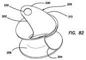
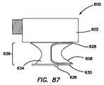
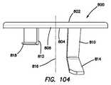
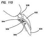
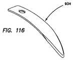
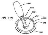
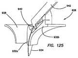
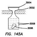
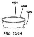
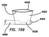
図82を参照すると、フィンガープルまたはタブ230を備えたシールド200の変形例が示されている。タブ230は、シールド200の第1の内側端部202のところでまたはこの近くで一体成形された状態で示されている。タブ230は、第1の内側端部202およびシールド200の頂端部212から延び、ユーザの指によるか器械、例えば把持器によるかのいずれかでユーザにより容易に把持されるようになった延長部を形成している。一変形例では、タブ230は、器械またはフィンガーの挿入場所を提供するよう構成された孔232を有する。別の変形例では、孔232は設けられない。タブ230は、これを全体として上方にまたは近位側の方向に引くと、シールド200が非拡張形態から拡張形態に変わるよう構成されている。タブ230を介して第1の端部202のところに加えられる上向きの力の結果として、第1の端部202の底部フランジ224は、シールド200の隣接の下側フランジ224から外れまたは離脱し、それにより第1の端部202を隣接のシールド200の部分のオーバーラップ曲率を備えた嵌合位置から離隔させる。タブ230の近位端部が上方に引かれているとき、これによりシールド200の垂直方向拡張が生じ、第1に、その結果として、第1の内側端部202が非拡張形態から離脱し、シールド200の残部が徐々に非拡張形態の嵌合並置状態から出て拡張形態にあるシールド200の渦巻き形状になる。図82は、非拡張形態にあるシールド200およびシールド200と一体に形成されたタブ230を示している。別の変形例では、タブ230は、接着剤、ステープルまたは他の締結具によってシールド200の第1の端部202に取り付けられた別個の要素である。さらに別の変形例では、タブ230は、シールド200に取り付けられたテザーを有し、別の変形例では、タブ230は、テザーであり、シールド200の延長部ではない。 Referring to FIG. 82, a modification of theshield 200 with finger pulls ortabs 230 is shown. Thetab 230 is shown integrally molded at or near the firstinner end 202 of theshield 200. Thetab 230 extends from the firstinner end 202 and the apex 212 of theshield 200 and is an extension that is easily gripped by the user either by the user's fingers or by an instrument such as a gripper. Is forming. In one variant, thetab 230 has ahole 232 configured to provide a place for an instrument or finger to be inserted. In another modification, theholes 232 are not provided. Thetab 230 is configured such that theshield 200 changes from the non-expanded form to the expanded form when pulled upward or proximally as a whole. As a result of the upward force applied to thefirst end 202 via thetab 230, thebottom flange 224 of thefirst end 202 disengages or detaches from the adjacentlower flange 224 of theshield 200. This separates thefirst end 202 from the mating position with overlapping curvature of theadjacent shield 200 portion. When the proximal end of thetab 230 is pulled upwards, this results in a vertical extension of theshield 200, firstly as a result, the firstinner end 202 disengages from the non-expanded form. The rest of theshield 200 gradually emerges from the non-expanded mated juxtaposed state and becomes a spiral of theshield 200 in the expanded form. FIG. 82 shows theshield 200 in the non-expanded form and thetab 230 formed integrally with theshield 200. In another variant, thetab 230 is a separate element attached to thefirst end 202 of theshield 200 by glue, staples or other fasteners. In yet another variant, thetab 230 has a tether attached to theshield 200, and in yet another variant, thetab 230 is a tether, not an extension of theshield 200.

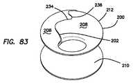
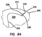
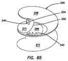
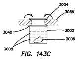
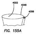
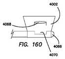
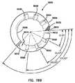
次に図83および図84を参照すると、ロック234を備えたシールド200が示されている。ロック234は、シールド200が非拡張形態にある間、シールド200の側方または直径方向寸法をロックするよう構成されている。シールド200が定位置に配置されているとき、周囲組織の力によりシールド200の側方または直径方向寸法が所望レベルよりも小さくなる場合がある。シールド200は、非拡張形態にある間、弛緩した通常の形態を有する場合があるが、シールド200の内蔵バイアスは、周囲の組織の力に打ち勝つには十分ではない場合があり、または特定の手技に関し、あるいは、中央ルーメン216に通されるべき特定の器械に関しあるいは標的組織の特に大きな検体に関して外科医の好みに至らない場合がある。いずれの場合においても、ロック234は、シールド200をロックしてその側方または直径方向寸法を実質的に固定された状態に保持し、そして特に、周囲組織からの力による側方または直径方向寸法の減少を阻止するよう構成されている。例えば、シールド200をシールド200の側方寸法よりも比較的小さい切開創または体口中に挿入されるべき場合、最初にシールド200を例えば図81に示されているコンパクトな形態に縮小する。コンパクトにされた形態にある間、シールド200を創部または体口中に挿入する。挿入状態のシールド200に応答した周囲組織の力は、シールド200を応力を受けていない弛緩状態の通常形態に戻す傾向のあるバイアスよりも大きいのが良い。かかる場合、外科医は、シールド200にとってまたは周囲組織をレトラクトするために大径の中央ルーメン216を要望する場合がある。次に、外科医は、シールド200を広げて大きな側方または大きな直径方向形態にし、そしてシールド200に向けられているロック234によりこの位置をロックする。一変形例では、ロック234は、シールド200の第1の内側端部202から見て近位側に或る距離を置いたところにかつ頂端部212の近くに配置された第1のノッチ236およびシールド200の第2の外側端部204から近位側に或る距離を置いたところにかつ頂端部212の近くに配置された第2のノッチ238を有する。ノッチ236,238は、シールド200の一端部202が非拡張形態においてシールド200の他端部204とオーバーラップした場所の近くに配置される。シールド200は、図83ではロック解除形態で示されている。シールド200をロックするため、シールド200を広げて大径中央ルーメン216を形成することによってシールド200を側方寸法について拡張する。第1のノッチ236を第2のノッチ238とオーバーラップさせてシールド200を固定された直径方向/側方寸法位置にロックし、シールド200の残部は、シールド200の周囲周りの円周方向の幾分かのオーバーラップ度を維持する。図84は、ロック形態において第2のノッチ238とオーバーラップしまたはインターロックした第1のノッチ236を示している。ロック形態にある間、第1の端部202の少なくとも一部分は、第2の端部204の少なくとも一部分の外部に位置し、その結果、第1のノッチ236の内面208の一部分が第2のノッチ238の外面210に向くようになる。シールド200をロック解除するため、ノッチ236,238を互いに外す。 Next, referring to FIGS. 83 and 84, ashield 200 with alock 234 is shown.Lock 234 is configured to lock the lateral or diametrical dimensions of theshield 200 while theshield 200 is in the non-expanded form. When theshield 200 is in place, the lateral or diametrical dimensions of theshield 200 may be smaller than the desired level due to the forces of surrounding tissue. Theshield 200 may have a relaxed normal form while in the non-expanded form, but the built-in bias of theshield 200 may not be sufficient to overcome the forces of surrounding tissue, or certain procedures. It may not reach the surgeon's preference regarding, or with respect to the particular instrument to be passed through thecentral lumen 216, or with respect to a particularly large specimen of target tissue. In either case, thelock 234 locks theshield 200 to keep its lateral or diametrical dimensions substantially fixed, and in particular the lateral or diametrical dimensions due to forces from surrounding tissue. It is configured to prevent the decrease of. For example, if theshield 200 should be inserted into an incision or body mouth that is relatively smaller than the lateral dimension of theshield 200, theshield 200 is first reduced to the compact form shown, for example, in FIG. While in the compacted form, theshield 200 is inserted into the wound or body mouth. The force of the surrounding tissue in response to the insertedshield 200 should be greater than the bias that tends to return theshield 200 to its unstressed relaxed normal form. In such cases, the surgeon may request a large diametercentral lumen 216 for theshield 200 or to retract the surrounding tissue. The surgeon then unfolds theshield 200 into a large lateral or large diametrical form and locks this position with alock 234 directed at theshield 200. In one variant, thelock 234 is located at a distance proximal to the firstmedial end 202 of theshield 200 and near the apex 212 and thefirst notch 236 and It has asecond notch 238 located proximal to the secondouter end 204 of theshield 200 and near the apex 212. Thenotches 236 and 238 are arranged near where oneend 202 of theshield 200 overlaps theother end 204 of theshield 200 in the non-expanded form. Theshield 200 is shown in the unlocked form in FIG. To lock theshield 200, theshield 200 is extended laterally by expanding theshield 200 to form a large diametercentral lumen 216. Thefirst notch 236 overlaps with thesecond notch 238 to lock theshield 200 in a fixed radial / lateral dimension position, leaving the rest of theshield 200 in the circumferential direction around theshield 200. Maintain a minute overlap. FIG. 84 shows afirst notch 236 that overlaps or interlocks with thesecond notch 238 in the locked form. While in the locked form, at least a portion of thefirst end 202 is located outside of at least a portion of thesecond end 204, so that a portion of theinner surface 208 of thefirst notch 236 is a second notch. It faces theouter surface 210 of 238. To unlock theshield 200, thenotches 236 and 238 are removed from each other.

上述したように、シールド200を巻くとともに/あるいは押し潰して小さな直径の状態にし、次にこれを創部または体口中に挿入することによってシールド200を創部または体口中に挿入するのが良い。シールド200の挿入は、ありふれた外科用器械、例えばクランプまたは把持器により容易に実施することができる。いったん挿入されると、シールド200は、当然のことながら、僅かに開き、組織は、その形態の外部に崩れるように撓む。一変形例では、シールドは、シールド200をこれが自然に閉鎖して至る僅かに大きな直径でロックすることができるロック234を有する。ロック234は、渦巻き状材料がオーバーラップしている第1および第2の端部202,204の近くでシールド200の外縁部に沿って設けられたノッチ236,238を有する。これらノッチ236,238は、ロック形態では互いにオーバーラップし、その結果、シールド200の内側端部の少なくとも一部分は、シールド200の外側端部の外部に位置するようスナップ動作する。ロック234の露出タブは、はさまれて、機械的インターロック箇所をもたらすオーバーラップ状態になる。 As mentioned above, it is preferable to insert theshield 200 into the wound or body mouth by rolling and / or crushing theshield 200 into a small diameter state and then inserting it into the wound or body mouth. Insertion of theshield 200 can be easily performed with common surgical instruments such as clamps or grippers. Once inserted, theshield 200 will, of course, open slightly and the tissue will flex to collapse out of its form. In one variant, the shield has alock 234 that can lock theshield 200 with a slightly larger diameter that leads to its spontaneous closure. Thelock 234 has notches 236,238 provided along the outer edge of theshield 200 near the first and second ends 202, 204 where the spiral material overlaps. Thesenotches 236 and 238 overlap each other in the locked form, so that at least a portion of the inner end of theshield 200 snaps to be located outside the outer end of theshield 200. The exposed tabs on thelock 234 are pinched and overlapped to provide a mechanical interlock.

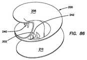
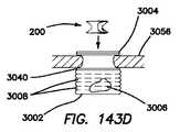
次に図85および図86を参照すると、シールド200に設けられたロック234の別の変形例が示されている。ロック234は、インターロック歯を有する。具体的に言えば、第1の組をなす外歯240がシールド200の第1の内側端部202の近くで外面210上に形成され、第2の組をなす内歯242がシールド200の第2の外側端部204の近くで内面208上に形成されている。第1の組をなす外歯240は、第1の内側端部202の近くで陥凹内に配置された状態で実質的に垂直に延びている。第2の組をなす内歯242は、第2の外側端部204の近くで陥凹内に配置された状態で実質的に垂直に延びている。外歯240および内歯242はまた、斜めであっても良い。一変形例では、歯240,242は、これらが減少側方寸法から増大側方寸法に動くと互いに容易に滑りまたは擦れ合うことができるよう傾けられている。歯の角度により、これら端部が互いにロックされるとともにシールド200が創部または体口のところの組織の力によって側方に縮小するのが阻止される。外歯240と内歯242は、シールド200の側方寸法の減少を阻止するために互いにインターロックするよう構成されている。複数の内歯242および複数の外歯240が第1および第2の端部202,204の近くで周囲の少なくとも一部分に沿って形成されており、シールド200がロックされる位置を必要に応じて調節することができ、それ故、側方寸法を所望に応じて固定することができるようになっている。歯240,242は、長手方向軸線218に対して垂直の中線内に位置した状態で示されているが、本発明は、垂直方向に沿うどこかの場所に設けられた歯を有しても良い。 Next, with reference to FIGS. 85 and 86, another modification of thelock 234 provided on theshield 200 is shown.Lock 234 has interlock teeth. Specifically, the first set ofouter teeth 240 is formed on theouter surface 210 near the firstinner end 202 of theshield 200, and the second set ofinner teeth 242 is the second set ofshield 200. It is formed on theinner surface 208 near theouter end 204 of 2. The first set ofexternal teeth 240 extend substantially vertically in a recessed position near the firstmedial end 202. The second set ofinternal teeth 242 extend substantially vertically in a recessed position near the secondouter end 204. Theexternal teeth 240 andinternal teeth 242 may also be oblique. In one variant, the teeth 240,242 are tilted so that they can easily slide or rub against each other as they move from the decreasing lateral dimension to the increasing lateral dimension. The angle of the teeth locks these ends together and prevents theshield 200 from shrinking laterally due to the force of tissue at the wound or mouth. Theouter teeth 240 and theinner teeth 242 are configured to interlock with each other to prevent a decrease in the lateral dimension of theshield 200. A plurality ofinternal teeth 242 and a plurality ofexternal teeth 240 are formed near the first and second ends 202, 204 along at least a part of the periphery, and the position where theshield 200 is locked is required as required. It can be adjusted and therefore the lateral dimensions can be fixed as desired. Theteeth 240, 242 are shown to be located within the midline perpendicular to thelongitudinal axis 218, but the present invention has teeth provided somewhere along the vertical direction. Is also good.

シールド200に設けられるロックの別の変形例では、シールド200は、内面から延びる突起を備える。突起は、フックのような形をしているのが良く、この突起は、シールド200の隣接の部分に設けられたノッチまたは開口部と嵌合するよう構成されるのが良い。一変形例では、突起は、第1の内側端部202および第2の外側端部204のうちの一方の近くに位置し、ノッチまたは開口部は、第1の内側端部202および第2の外側端部204のうちの他方のものの近くに形成される。 In another variant of the lock provided on theshield 200, theshield 200 comprises a protrusion extending from the inner surface. The protrusion may be shaped like a hook, and the protrusion may be configured to fit into a notch or opening provided in an adjacent portion of theshield 200. In one variant, the protrusion is located near one of the firstinner end 202 and the secondouter end 204, and the notch or opening is the firstinner end 202 and the secondouter end 204. It is formed near the other of the outer edges 204.

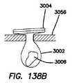
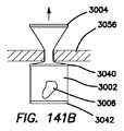
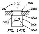
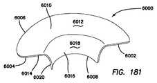
シールド200は、体に設けられた創部または体口を包囲する組織を手術中、鋭利な物体、例えばブレードおよび細切器から保護する。創部、体口、切開創、体開口部という用語は、本明細書においては区別なく用いられる。創部は、一般に、腹腔鏡下手術または他形式の手術のために腹壁を穿通した低侵襲切開創部である。シールド200は、拡張形態では、創部または体口中に挿入されると外向きの力を生じさせる渦巻き体に形成された材料のリボンから成る渦巻きばねである。シールド200はまた、創部または体口内の組織をレトラクトし、腹壁を横切りまたは中央ルーメン216を介する体口を通る開口部を提供し、中央ルーメン216は、長手方向軸線218に沿って見たときに形状が全体として円形である。シールド200の一変形例では、シールド200は、湾曲しておらず、全体として扁平な材料のリボンを円筒形または円錐形形態に巻くことによって作られている。別の変形例では、湾曲したリボンシールド200は、横から見たときにC字形の垂直輪郭を有する。頂端部212および底端部214とも呼ばれる近位縁部および遠位縁部は、頂部フランジ222および底部フランジ224をそれぞれ形成するシールド200の中間部分よりも直径が大きい。このC字形形態は、有利には、創部開口部のところで組織を入れ、そしてアンカー状固定手段を提供し、従って、シールド200は、通常の使用中、創部または体口から軸方向に容易には離脱することがないようになる。一変形例では、C字形は、図75に示されているように放物線である。放物線の頂点は、長手方向軸線218に垂直な平面内に位置している。別の変形例では、この頂点は、頂端部212または底端部214と垂直中線との間に位置する。 Theshield 200 protects the tissue surrounding the wound or mouth provided on the body from sharp objects such as blades and shredders during surgery. The terms wound, body mouth, incision, and body opening are used interchangeably herein. The wound is generally a minimally invasive incision that penetrates the abdominal wall for laparoscopic surgery or other forms of surgery. In its extended form, theshield 200 is a spiral spring made of a ribbon of material formed in a spiral that produces an outward force when inserted into the wound or body mouth. Theshield 200 also retracts tissue within the wound or body mouth and provides an opening across the abdominal wall or through the body mouth via thecentral lumen 216, when thecentral lumen 216 is viewed along thelongitudinal axis 218. The shape is circular as a whole. In one variant of theshield 200, theshield 200 is made by winding a ribbon of non-curved, generally flat material in a cylindrical or conical form. In another variant, thecurved ribbon shield 200 has a C-shaped vertical contour when viewed from the side. The proximal and distal edges, also referred to as the apex 212 and thebottom end 214, are larger in diameter than the middle portion of theshield 200 forming thetop flange 222 and thebottom flange 224, respectively. This C-shape advantageously inserts tissue at the wound opening and provides an anchoring means, thus theshield 200 is easily axially from the wound or body mouth during normal use. You will not be able to leave. In one variant, the C-shape is a parabola, as shown in FIG. The apex of the parabola is located in a plane perpendicular to thelongitudinal axis 218. In another variant, this apex is located between the apex 212 or bottom 214 and the vertical midline.

シールド200を創部または体口から取り出すことは、最初にインターロック特徴部234を互いに離脱させ、シールド200の露出状態の内側コーナー部を掴み、そしてこれを材料の渦巻き方向に内方にカールさせ、次にこれを長手方向軸線に沿って上方に引き上げて創部または体口から出すことによって達成される。シールド200は、有利には、螺旋状に進んで拡張形態の螺旋形態になる。シールド200を手の指でまたはありふれた外科用器械、例えばクランプまたは把持器を用いて引き出すことができる。シールド200の一変形例は、耐切断性であるが、柔軟性のプラスチック材料で作られる。材料の選択および厚さは、保護特徴をもたらす。シールド200は、挿入されたり取り出されたりするほど柔軟性があるが、固定されたままの状態を保って保護を提供するのに十分剛性である。 Removing theshield 200 from the wound or body mouth first disengages the interlock feature 234 from each other, grabs the exposed inner corner of theshield 200, and curls it inward in the swirling direction of the material. This is then achieved by pulling it up along the longitudinal axis and out of the wound or body mouth. Theshield 200 advantageously travels spirally into an expanded spiral form. Theshield 200 can be pulled out with the fingers of the hand or using common surgical instruments such as clamps or grippers. One variant ofShield 200 is made of a plastic material that is cut resistant but flexible. The choice and thickness of the material provides protective features. Theshield 200 is flexible enough to be inserted and removed, but rigid enough to remain fixed and provide protection.

シールド200は、幾つかの有利な特徴を提供する。シート200によって提供される重要な一特徴は、このシールドによって周囲の組織が鋭利な物体、例えばブレード、小刀および細切器から保護されるということにある。シールド200はまた、これが収容される収容袋のための保護手段となり、それにより収納袋が鋭利な物体によって穿通されまたは切断されるのが阻止され、それにより生物学的検体の収容状態が漏れの恐れを減少させた状態で維持されるようにする。頂部フランジ222は、組織のための広い貴部または切断板状の保護手段となり、袋表面が創部または体口を包囲する。頂部フランジ222は、組織辺縁および/または収容袋の上に位置し、これを覆うとともに/あるいは保護する。シールド200の中間部分はまた、創部または体口のところの組織を遮蔽し、更に収容袋が用いられる場合、シールドが収容されている収容袋を保護する。さらに中間部分により、有利には、外科医は、ブレードを用いて深いところに到達して長手方向軸線に垂直なまたはこの上の中間水平面のところの近くで組織検体を切断することができ、更にシールド200の中間平面を越えて遠位側に達して組織検体を切断することができる。というのは、シールド200の垂直長さ全体が周囲組織および収容袋に対して保護手段となるからである。 Theshield 200 offers several advantageous features. An important feature provided by thesheet 200 is that this shield protects the surrounding tissue from sharp objects such as blades, knives and shredders. Theshield 200 also provides a protective measure for the containment bag in which it is contained, thereby preventing the storage bag from being pierced or cut by sharp objects, thereby leaking the containment state of the biological specimen. Try to maintain a reduced fear. Theapex flange 222 provides a wide noble or cut plate-like protective measure for the tissue, with the bag surface surrounding the wound or body mouth. Thetop flange 222 is located on the tissue margin and / or the containment bag to cover and / or protect it. The middle portion of theshield 200 also shields the tissue at the wound or body mouth and, if a containment bag is used, also protects the containment bag containing the shield. Further intermediates allow the surgeon to use a blade to reach deeper and cut tissue specimens perpendicular to or near the intermediate horizontal plane above it, and further shielded. Tissue specimens can be cut beyond the 200 intermediate plane and reaching the distal side. This is because the entire vertical length of theshield 200 provides protection against surrounding tissue and the containment bag.

シールド200の別の利点は、このシールドが定着特徴部を有するということにある。シールド200は、有利には、C字形設計により創部および体口内にそれ自体定着するよう構成されている。定着特徴は、細切手技を劇的に容易にかつ迅速にする。というのは、これには、通常の手技中にシールド200を定位置に保持するための縫合糸または別の手が不要だからである。デュアルフランジ(頂部および底部222,224)がシールド200を定着させるために設けられ、それにより組織または腹壁をC字形の陥凹内に捕捉する。シールドは、創部内部中への位置決めのための遠位定着部材および創部開口部の外部への位置決めのための近位定着部材を有する。頂部フランジであるにせよ底部フランジであるにせよいずれにせよ単一のフランジもまた本発明の範囲に含まれる。さらに、頂部フランジ222および底部フランジ224は、それぞれ、頂端部212および底端部214の周囲全体に沿って延びているものとして示されているが、本発明にはこれには限定されず、頂部および底部フランジ222,224のうちの1つまたは2つ以上が周囲の少なくとも一部分の周りに延びても良い。かかる変形例では、フィンガー状の延長部が円周方向底部フランジ224に代えて形成されるのが良い。フィンガーは、容易な挿入を可能にするよう長手方向に沿って容易に撓むことができ、次に、腹壁または他の組織構造体もしくは体口の下の停留位置に半径方向外方にばね作用で動くことができる。また、頂部フランジ222は、図79に示されているように底部フランジ224よりも長い距離にわたって半径方向外方に延びるのが良く、また、その逆の関係がなりたっても良く、それにより広い切断板状表面を提供することができる。 Another advantage of theshield 200 is that the shield has a anchoring feature. Theshield 200 is advantageously configured to anchor itself in the wound and body mouth by a C-shaped design. The anchoring feature makes the stamping technique dramatically easier and faster. This is because it does not require sutures or another hand to hold theshield 200 in place during a normal procedure. Dual flanges (top and bottom 222,224) are provided to anchor theshield 200, thereby capturing the tissue or abdominal wall within a C-shaped recess. The shield has a distal anchoring member for internal positioning of the wound and a proximal anchoring member for external positioning of the wound opening. A single flange, whether it is a top flange or a bottom flange, is also included within the scope of the invention. Further, thetop flange 222 and thebottom flange 224 are shown to extend along the entire perimeter of thetop end 212 andbottom end 214, respectively, but are not limited to this in the present invention. And one or more of the bottom flanges 222,224 may extend around at least a portion of the perimeter. In such a modification, it is preferable that the finger-shaped extension portion is formed in place of thecircumferential bottom flange 224. The fingers can be easily flexed along the longitudinal direction to allow easy insertion and then radial outward spring action to the anchorage position under the abdominal wall or other tissue structure or body mouth. Can move with. Also, thetop flange 222 may extend radially outward over a longer distance than thebottom flange 224, as shown in FIG. 79, and vice versa, thereby resulting in a wider cut. A plate-like surface can be provided.

さらに、シールド200は、有利には、創部または体口中に容易に挿入したりこれから容易に取り出したりすることができるようになっている。シールド200は、垂直に拡張した形態および垂直に拡張を解除した(非拡張状態の)形態を有し、これら形態は、シールド200に垂直可変性を与えている。これは、シールド200の一端を単に近位側に引くことによってシールド200の容易な取り出しが行われ、その結果、シールド200は、隣接のかつオーバーラップしたフランジおよび/または陥凹から外れて嵌合非拡張形態から螺旋状に進んで拡張渦巻き形状になる。シールド200を掴んで垂直に引くのを助けるタブ、穴、および/またはテザー230が設けられている。さらに、嵌合または非拡張形態にある間、シールド200は、シールド200をそれ自体に巻きまたはカールさせて小さなまたは締まった円を形成するとともにそれ自体の周りにより多くの旋回体を形成することによってコンパクトな形態に動くことができる。シールド200は、有利には、コンパクトにされた形態を解除することによって側方にコンパクトな形態から動き、ついで、シールドは、比較的大きな側方寸法を有する通常の弛緩形態を取る。別の拡大された形態もまた、シールド200によって提供され、かかる形態では、通常のまたは弛緩形態よりも大きな側方または直径方向位置をシールド200に形成されているロック234により定位置でロックすることができる。シールド200の側方可変性により、側方寸法を減少させることができ、それにより創部または体口中への容易な挿入が可能になる。また、ロックされた直径増大位置から、シールドを単にロック解除するとともに/あるいはシールド200をロック解除し、次にシールドそれ自体をカールさせて締まった形態にすることによって、シールド200をロック解除して側方における寸法を減少させることができ、それにより創部または体口からの取り出しが容易になる。 In addition, theshield 200 is advantageously adapted to be easily inserted into or removed from the wound or body mouth. Theshield 200 has a vertically expanded form and a vertically unextended (non-expanded) form, which gives theshield 200 vertical variability. This allows easy removal of theshield 200 by simply pulling one end of theshield 200 to the proximal side so that theshield 200 fits out of the adjacent and overlapping flanges and / or recesses. It spirals from the non-expanded form to an expanded spiral shape. There are tabs, holes, and / ortethers 230 that help to grab theshield 200 and pull it vertically. In addition, while in the mated or non-expanded form, theshield 200 winds or curls theshield 200 around itself to form a small or tight circle and forms more swivels around itself. It can move into a compact form. Theshield 200 advantageously moves from a laterally compact form by releasing the compacted form, and then the shield takes a normal relaxed form with a relatively large lateral dimension. Another expanded form is also provided by theshield 200, in which a larger lateral or diametrical position than the normal or relaxed form is locked in place by alock 234 formed on theshield 200. Can be done. The lateral variability of theshield 200 allows for reduced lateral dimensions, which allows easy insertion into the wound or body mouth. Also, from the locked diameter increase position, theshield 200 is unlocked by simply unlocking and / or unlocking theshield 200 and then curling the shield itself into a tighted form. Lateral dimensions can be reduced, which facilitates removal from the wound or body mouth.

また、シールド200は、有利には、自己配備性である。シールド200をコンパクトにされた側方形態にカールさせた後、シールド200を容易に創部または体口中に挿入し、次に解除し、すると、シールドは、そのばねバイアスに起因して寸法が増大する傾向がある。側方におけるこのスプリングバック作用は、シールド200を僅かな労力で創部または体口内に自動的に嵌め込むのを助け、それと同時に、保護作用およびレトラクションを組織および/または収容袋に提供し、それによりこれら両方を通常の手技中に遭遇する場合のある鋭利な物体から離したままにする。 Also, theshield 200 is advantageously self-deployable. After curling theshield 200 into a compacted lateral form, theshield 200 is easily inserted into the wound or body mouth and then released, and the shield increases in size due to its spring bias. Tend. This lateral springback action helps theShield 200 to automatically fit into the wound or body mouth with little effort, while at the same time providing protective action and retraction to the tissue and / or containment bag. Keeps both of these away from sharp objects that may be encountered during normal procedures.

さらに、垂直に拡張解除した形態にある間、シールド200は、全体的外径がC字形または砂時計型であり、この場合、近位端部は、長手方向軸線から半径方向外方にラッパ状に広がり、シールド200の遠位端部は、長手方向軸線から半径方向外方にラッパ状に広がり、くびれ部は、シールドの近位端部と遠位端部との間の平面に沿って最も狭い側方寸法である。シールド200の遠位端部のところのフレア(ラッパ状広がり部)は、有利には、標的組織をシールド200中に案内してこれを通って動かすのを容易にする斜面または漏斗状部となる。 Further, while in the vertically unextended form, theshield 200 has an overall outer diameter of C-shaped or hourglass-shaped, in which case the proximal end is trumpeted radially outward from the longitudinal axis. Spread, the distal end of theshield 200 wraps radially outward from the longitudinal axis, and the constriction is the narrowest along the plane between the proximal and distal ends of the shield. It is a lateral dimension. The flare (trumpet-like spread) at the distal end of theshield 200 is advantageously a slope or funnel that facilitates guiding the target tissue into and moving through theshield 200. ..

シールド200の可撓性により、シールド200は、挿入、配備、取り出しに秀でており、拡張に起因してアンカーになることができる。可撓性は、有利には、保護作用を周囲組織および/または収容袋に提供する能力に対してバランスが取られている。シールド200が提供する保護作用は、適切に実施されると、手動による細切手技にとって十分であり、他方、個人的な細切技術を用いる自由度を外科医に与える。シールド200は、収納袋の口中に挿入され、このシールド200はまた、収容袋のネック内または収容袋の主要な入れ物内に配置できる。収容袋は、シールド200を包囲し、この収容袋は、組織/体口とシールド200との間に捕捉される。シールド200は、周囲組織ならびに周囲の収容袋材料をレトラクトするのに役立つ。シールド200は、十分な力を収容袋に及ぼして収容袋が実質的に固定された状態の定位置に保たれるようにし、その結果、収容袋が創部または体口中に滑り込まないようになる。袋の十分な量の近位端部がシールドの近位側に位置するとともに患者の外面、例えば腹部の上に位置し、それにより汚染の防止に役立つブランケットを形成する。シールド200は、収容袋の口を接近可能な開放形態に保持するとともに手動または電動式細切装置を受け入れるとともに支持するよう構成されている。 Due to the flexibility of theshield 200, theshield 200 excels at insertion, deployment and removal and can be an anchor due to expansion. Flexibility is advantageously balanced against the ability to provide protective effects to the surrounding tissue and / or the containment bag. The protective action provided by theShield 200, when properly performed, is sufficient for manual postage stamping techniques, while giving the surgeon the freedom to use personal postage stamp techniques. Theshield 200 is inserted into the mouth of the storage bag, and theshield 200 can also be placed in the neck of the storage bag or in the main container of the storage bag. The containment bag surrounds theshield 200, which is captured between the tissue / body mouth and theshield 200. Theshield 200 helps to retract the surrounding tissue as well as the surrounding containment bag material. Theshield 200 exerts sufficient force on the containment bag to keep it in place in a substantially fixed position, thus preventing the containment bag from slipping into the wound or body mouth. A sufficient amount of the proximal end of the bag is located proximal to the shield and on the patient's outer surface, eg, the abdomen, thereby forming a blanket that helps prevent contamination. Theshield 200 is configured to hold the mouth of the containment bag in an accessible open form and to accept and support a manual or electric shredding device.

別の変形例では、シールド200は、膣管中に挿入されるようになっており、従って、図示のように長さが長い。シールド200は、配備を助ける形状記憶部分を更に有するのが良い。シールド200は、内因性サンプルの確実かつ安全な取り出しを可能にし、使用するのが容易であり、それにより手術時間およびコストが減少する。シールド200は、収容袋と組み合わせた状態で、組織サンプル採取および取り出し操作中に場合によっては悪性細胞による健常な組織の汚染の恐れを減少させるのを助ける。 In another variant, theshield 200 is designed to be inserted into the vaginal canal and is therefore longer as shown. Theshield 200 may further have a shape memory portion to aid deployment. TheShield 200 allows for reliable and safe removal of endogenous samples and is easy to use, thereby reducing surgery time and cost. Theshield 200, in combination with the containment bag, helps reduce the risk of contamination of healthy tissue by potentially malignant cells during tissue sampling and removal operations.

次に図54〜図59を参照して本発明の袋310について説明する。袋310は、単一の開口部または口312を有する。袋の口312のところでまたはその近くで、半硬質の圧縮性プラスチックリング314が袋310に連結されている。リング314は、円形のまたは大きな形態から楕円形のまたは小さい形態に圧縮可能であり、その結果、袋310を小さな切開創に通して挿入することができるようになっている。患者の体内にいったん配置されると、弾性リング314は、その元の非圧縮状態の大きな形態に拡張し、それにより袋310の口312をこのリングと一緒に開く。患者の体内に扁平な状態に配置されると、リング314は、袋310の口312を明確に構成し、開口部312は、リング314がなければ、腹腔鏡観察下において見るのが困難な場合がある。場合によっては、袋310の開口部312は、見つけるのが困難な場合がある。次に、組織を開口部312中に明確に配置して開口部312を越えて配置しないようにするよう開口部312を患者の体内で配向させなければならない。本発明では、拡張状態のリング314は、袋310の頂部上に配置されると、リング314内に配置された組織がリング314を切開創に向かって持ち上げたときに袋310内に落ち着くようにする。空の袋310は、平坦な表面上で平べったい状態で位置し、リング314は、袋310の上方で自然に落下する。弾性リング314により、袋310は、腹腔内での補助なしで開いたままでいることができ、それにより組織の捕捉を容易にすることができる。 Next, thebag 310 of the present invention will be described with reference to FIGS. 54 to 59. Thebag 310 has a single opening ormouth 312. A semi-rigid compressibleplastic ring 314 is attached to thebag 310 at or near the mouth of thebag 312. Thering 314 is compressible from a circular or large form to an elliptical or small form so that thebag 310 can be inserted through a small incision. Once placed inside the patient's body, theelastic ring 314 expands into its original uncompressed large form, thereby opening themouth 312 of thebag 310 with this ring. When placed flat inside the patient's body, thering 314 clearly constitutes themouth 312 of thebag 310 and theopening 312 is difficult to see under laparoscopic observation without thering 314. There is. In some cases, theopening 312 of thebag 310 can be difficult to find. Theopening 312 must then be oriented within the patient's body so that the tissue is clearly placed in theopening 312 and not beyond theopening 312. In the present invention, the expandedring 314 is placed on top of thebag 310 so that the tissue placed in thering 314 settles in thebag 310 when thering 314 is lifted towards the incision. To do. Theempty bag 310 is positioned flat on a flat surface, and thering 314 naturally falls above thebag 310. Theelastic ring 314 allows thebag 310 to remain open without assistance in the abdominal cavity, thereby facilitating tissue capture.

組織検体をリング314内に配置した後、リング314を切開創に向かって引き上げる。外科医が袋310を切開創に向かって引き上げるのを助けるテザー316が袋310の口312の近くにが設けられている。テザー316は、近位端部のところに位置するタグ318を有するのが良く、このタグは、袋310が患者の体内に配置されても患者の体外に保たれる。タグ318はまた、患者の内部で容易に見つけられる。大きなタグ318は、テザー316の存在場所を迅速に突き止めて必要な場合、テザー316を引くのを助ける。テザー316はまた、袋310を閉鎖状態に引き締めるよう構成されているのが良く、その目的は、袋310の内容物がこぼれ出るのを阻止することにある。変形例として、袋310に連結されるとともにリング314の下にまたは上に配置された追加の引き締めひもが設けられても良く、その結果、引き締めひもは、袋を円周方向に閉じることになる。閉じまたは密封する他の仕方、例えば圧力嵌めまたはジッパもまた設けられても良い。 After placing the tissue specimen in thering 314, thering 314 is pulled up towards the incision. Atether 316 is provided near themouth 312 of thebag 310 to help the surgeon pull thebag 310 toward the incision. Thetether 316 preferably has atag 318 located at the proximal end, which is kept outside the patient's body even when thebag 310 is placed inside the patient's body.Tag 318 is also easily found inside the patient. Thelarge tag 318 helps to quickly locate thetether 316 and pull thetether 316 if needed. Thetether 316 is also preferably configured to tighten thebag 310 into a closed state, the purpose of which is to prevent the contents of thebag 310 from spilling out. As a variant, an additional lacing string may be provided that is connected to thebag 310 and placed below or above thering 314, so that the lacing string closes the bag circumferentially. .. Other methods of closing or sealing, such as pressure fitting or zipper, may also be provided.

袋310を引いて切開創の近くに配置すると、リング314をその拡張形態からその圧縮形対に圧縮してリング314を小さな切開創中に通して引くことができるようにする。リング314を、把持器を用いてまたは切開創開口部を通って手で圧縮する。リング314を切開創中に引き通した後、十分な量の袋310をリングと一緒に引き、これが患者の腹部の一部分上に載せられてこれを覆うようにする。それ故、袋310は、患者の体外で切開創周りにエプロン効果を生じさせるために十分に大きくなければならない。リング314および袋310の一部が患者の体外にある状態で、袋310の残部および組織検体は、患者の体内に位置したままである。 When thebag 310 is pulled and placed near the incision, thering 314 is compressed from its expanded form into its compressed pair so that thering 314 can be pulled through the small incision.Ring 314 is manually compressed using a gripper or through an incision opening. After pulling thering 314 through the incision, a sufficient amount ofbag 310 is pulled with the ring so that it rests on and covers a portion of the patient's abdomen. Therefore, thebag 310 must be large enough to create an apron effect around the incision outside the patient's body. The rest of thebag 310 and the tissue specimen remain located inside the patient, with thering 314 and part of thebag 310 outside the patient's body.

リング314の断面は、円形であるのが良く、この断面は、可撓性を与えるよう中空の中央部を有するのが良い。一変形例では、リング314は、断面が楕円形、細長い形または長円形である。図示の変形例では、リング314は、8の字に似ているまたは2つの連結された円形断面を有する形状を有し、その結果、小さな谷部320が円相互間に生じる。一般的に言って、リング314の断面は、その幅よりも大きな長さを有する。この細長い断面により、リング314を外方にまたは内方にひっくり返して袋310をリング314それ自体の上に丸く巻くことによってリング314をそれ自体回しまたはひっくり返すことができる。リング314を逆の方向に巻くと、袋310をリング314から広げることができる。リング314の細長い断面は、有利には、袋310の側壁をリング314上に丸く巻いた状態に保つ。断面が円形である場合、リング314を容易にそれ自体回すことができ、それにより袋310の丸く巻いた側壁をほぐすことができる。リング314のそれ自体の巻きにより、袋310が上方に引き上げられるとともに袋310内の検体が切開創開口部の近くに至る。袋310の巻き作用は、患者の体内に位置している袋310の嵩を減少させ、しかも患者の体外に正確に形成されたぴんと張ったエプロンを生じさせる。袋310をしっかりしすぎるほどレトラクトした場合、リング314は、捩曲がる場合がある。次に、組織検体をブレードまたは電子式細切器で細切して小さな切開創を通過することができ、そして袋310から取り出すことができる寸法形状にすることによって組織検体を袋310から引き出す。袋310の側壁328をそれ自体丸く巻くと、図59に示されている配備を容易にするためにリング314に隣接して位置するロール330を形成することができる。リング314を押し潰してリング314の圧縮長さが容易な挿入を可能にするようロール330の長さと整列するようにする。 The cross section of thering 314 may be circular, and the cross section may have a hollow central portion to provide flexibility. In one variant, thering 314 has an elliptical, elongated or oval cross section. In the illustrated variant, thering 314 has a shape that resembles a figure eight or has two connected circular cross sections, resulting insmall valleys 320 between the circles. Generally speaking, the cross section of thering 314 has a length greater than its width. This elongated cross section allows thering 314 to be turned or turned over by itself by flipping thering 314 outward or inward and rolling thebag 310 over thering 314 itself. Thebag 310 can be unfolded from thering 314 by winding thering 314 in the opposite direction. The elongated cross section of thering 314 advantageously keeps the side wall of thebag 310 in a rounded state on thering 314. If the cross section is circular, thering 314 can easily be turned by itself, thereby loosening the rounded side walls of thebag 310. The winding of thering 314 itself causes thebag 310 to be pulled upwards and the specimen in thebag 310 to approach the incision opening. The wrapping action of thebag 310 reduces the bulk of thebag 310 located inside the patient's body, yet results in a taut apron that is precisely formed outside the patient's body. If thebag 310 is retracted too tightly, thering 314 may twist. The tissue sample is then withdrawn from thebag 310 by chopping the tissue sample with a blade or electronic shredding to a size that allows it to pass through a small incision and withdraw from thebag 310. Theside wall 328 of thebag 310 can itself be rolled to form aroll 330 located adjacent to thering 314 to facilitate deployment as shown in FIG. 59. Thering 314 is crushed so that the compression length of thering 314 is aligned with the length of theroll 330 for easy insertion.

特に図55および図56を参照すると、リング314は、自由端部を互いに結合することによって円または他の形状に形作られるプラスチックの単一の細長い小片322で形成されている。別の変形例では、リング314は、2つまたは3つ以上の部品、例えば2つの半円で作られ、これら2つの半円は、一緒になって同一半径の円を構成する。端部は、互いに連結されておらず、袋310の口のところのスリーブ内で通常の湾曲した形態に保持される。多部品構成型リング314は、小さな形態へのリング314の圧縮を容易にする。リング314は、高さが約0.38インチ(9.65mm)、幅が0.18インチ(4.57mm)、長さが約38インチ(96.52cm)である。リング314を形成する材料の厚さは、約0.18インチ(4.57mm)である。 In particular, with reference to FIGS. 55 and 56, thering 314 is formed of a single elongated piece ofplastic 322 that is formed into a circle or other shape by joining the free ends together. In another variant, thering 314 is made up of two or more parts, such as two semicircles, which together form a circle of the same radius. The ends are not connected to each other and are held in the usual curved form within the sleeve at the mouth of thebag 310. Themulti-component ring 314 facilitates compression of thering 314 into smaller forms. Thering 314 is approximately 0.38 inches (9.65 mm) high, 0.18 inches (4.57 mm) wide, and approximately 38 inches (96.52 cm) long. The thickness of the material forming thering 314 is about 0.18 inches (4.57 mm).

特に図57〜図59を参照すると、袋310は、材料の単一のシート324で作られている。材料シート324は、長さ方向に折り畳まれるとともに側部がヒートシールされ、それによりシーム326が形成されている。どの袋310でもその最も弱い部分は、溶接シーム326の周りの領域である。図57で理解できるように、検体を取り出す際に力が最も集中する可能性のある袋310の底部のところには溶接シーム326が設けられておらず、それにより袋310は、大きな臨界強度を有する。また、袋310の材料は、透明である4.2ミルInzii(登録商標)フィルムで作られ、この材料により、外科医は、手術中、袋310の側部越しに見ることができる。袋310越しに見ることができるので、視覚化を達成するために袋310の側部を穴あけすることは不要である。フィルムは、弾性であり、袋310に良好なレトラクションを与える。袋310はまた、ポリウレタンコーティングが施されたU‐5746リップ‐ストップナイロンで作られても良い。ポリウレタンコーティングは、フィルムを気密かつヒートシール可能にする。U‐5746は、Inzii(登録商標)フィルムよりも強固であるが、レトラクションの小さい軍事用材料であり、不透明である。袋310は、長さが約16インチ(40.64cm)であり、口312のところの幅は、12インチ(30.48cm)である。袋310の底部は、口312から約12.4インチ(31.50cm)の距離のところで側壁328と約45°の角度をなしている。袋310は、約0.2インチ(5.10mm)の厚さを有し、シーム326のところでは、袋310は、厚さが約2倍である。別の変形例では、袋310は、偶発的な穴あけに対して大きな耐性をもたらすよう一方の袋が別の袋の内部に位置する二重袋である。別の変形例では、袋310の底部分だけが二重壁構造で補強される。袋310は、漏れ止めでありかつウィルスの侵入を阻止する。 In particular, with reference to FIGS. 57-59, thebag 310 is made of a single sheet ofmaterial 324. Thematerial sheet 324 is folded in the length direction and the sides are heat-sealed, whereby theseam 326 is formed. The weakest part of anybag 310 is the area around theweld seam 326. As can be seen in FIG. 57, there is noweld seam 326 at the bottom of thebag 310 where the force may be most concentrated when removing the specimen, thereby causing thebag 310 to have a high critical strength. Have. Also, the material of thebag 310 is made of transparent 4.2 mil Inzi® film, which allows the surgeon to see through the sides of thebag 310 during surgery. Since it can be seen through thebag 310, it is not necessary to drill the sides of thebag 310 to achieve visualization. The film is elastic and gives thebag 310 good retraction. Thebag 310 may also be made of U-5746 lip-stop nylon with a polyurethane coating. The polyurethane coating makes the film airtight and heat sealable. U-5746 is a military material that is stronger than Inzii® film, but has less retraction, and is opaque. Thebag 310 is about 16 inches (40.64 cm) long and 12 inches (30.48 cm) wide at themouth 312. The bottom of thebag 310 forms an angle of about 45 ° with theside wall 328 at a distance of about 12.4 inches (31.50 cm) from themouth 312. Thebag 310 has a thickness of about 0.2 inches (5.10 mm), and at theseam 326, thebag 310 is about twice as thick. In another variant, thebag 310 is a double bag in which one bag is located inside the other bag to provide greater resistance to accidental drilling. In another variant, only the bottom portion of thebag 310 is reinforced with a double wall structure. Thebag 310 is a leak-proof and prevents the invasion of viruses.

上述したように、シールドが提供されて袋310と関連して用いられるのが良い。袋310を患者の体内に配置して切開創に通して引いた後、シールドを収容袋310の口312中に挿入する。シールドは、厚手のプラスチックで作られており、このシールドは、プラスチック袋310が標的組織を細切するために外科医によって用いられるブレードによって偶発的に切断されないよう保護する。シールドはまた、切断板としても役立つ場合があり、外科医は、必要ならば標的組織を切断板に当てた状態で切断することができる。袋310はまた、上述したレトラクタとともに用いることができ、この場合、袋310を切開創に通して引くと、レトラクタを袋310の口312内に配置し、切開創の存在場所のところの組織および袋310をレトラクトし、その後にシールドをレトラクタ内に配置して検体を取り出す。 As mentioned above, a shield may be provided and used in connection with thebag 310. After thebag 310 is placed in the patient's body and pulled through the incision, the shield is inserted into themouth 312 of thecontainment bag 310. The shield is made of thick plastic, which protects theplastic bag 310 from being accidentally cut by a blade used by the surgeon to shred the target tissue. The shield may also serve as a cutting plate, allowing the surgeon to cut the target tissue against the cutting plate if desired. Thebag 310 can also be used with the retractor described above, in which case when thebag 310 is pulled through the incision, the retractor is placed in themouth 312 of thebag 310 and the tissue at the location of the incision and Thebag 310 is retracted, after which the shield is placed in the retractor and the specimen is removed.

図60〜図63を参照すると、袋導入器またはフォーク410が小さな切開創を通って収容袋310を患者の体腔内に導入するために用いられている。導入器410は、手術野中への袋310の配置を容易にする。フォーク410は、近位端部412および遠位端部414を有している。ハンドル416が近位端部412のところに設けられている。第1の枝部418および第2の枝部420がハンドル416から遠位側に延びて実質的にフォーク状の形態を形成している。枝部418,420は、等しい長さのものである。枝部418,420は、任意適当な断面を有することができ、これら枝部は、十分な距離だけ互いに間隔を置いて配置されている。枝部418,420は、ステンレス鋼で作られ、これら枝部は、図60に示されているように射出成形プラスチックまたは金属ハンドル416に連結されている。この設計例では、枝部418,420を有するスチールロッドが射出成形ハンドル416中に挿入されてこれに連結され、それにより小さな輪郭を備えたフォーク410の実現が可能であるが、このようにすることは、製作するのが高価でありかつ時間がかかる。図61では、フォーク410は、単一の材料片で作られ、この場合、ハンドル416と枝部418,420の両方は、一体形構造を形成するよう射出成形される。この設計例は、大きな輪郭および弱い設計という代償を払って、製造するのが最も容易でありかつ費用が最も安い。 With reference to FIGS. 60-63, a bag introducer orfork 410 is used to introduce thecontainment bag 310 into the patient's body cavity through a small incision. Theintroducer 410 facilitates placement of thebag 310 in the surgical field. Thefork 410 has aproximal end 412 and adistal end 414. Ahandle 416 is provided at theproximal end 412. Thefirst branch 418 and thesecond branch 420 extend distally from thehandle 416 to form a substantially fork-like shape. Thebranches 418 and 420 are of equal length. The branches 418,420 can have any suitable cross section, and these branches are spaced apart from each other by a sufficient distance. The branches 418,420 are made of stainless steel and these branches are connected to an injection molded plastic or metal handle 416 as shown in FIG. In this design example, a steel rod with branches 418,420 is inserted into and connected to the injection moldedhandle 416, which allows the realization of afork 410 with a small contour, but in this way. That is, it is expensive and time consuming to manufacture. In FIG. 61, thefork 410 is made of a single piece of material, in which case both thehandle 416 and thebranches 418, 420 are injection molded to form an integral structure. This design example is the easiest and cheapest to manufacture at the cost of a large contour and a weak design.

使用にあたり、特に図62および図63を参照すると、収容袋310の底部をテザー316およびタグ318がハンドル416の近くに配置された状態で枝部418,420相互間に配置する。袋310の底縁部を枝部418,420が袋310の端部を僅かに越えて延びた状態で枝部418,420上に折り返す。それ故、枝部418,420は、袋310の幅よりも僅かに長い。ハンドル416を掴んでこれを回し、それにより袋310が均等に管状ロール330の状態に丸く巻くことができ、ついには、抵抗を感じるようになる。袋310を体内領域内への導入が可能な最小サイズまで縮小する。弾性リング314を押し潰し、袋310を丸く巻き、ついには袋310がぴんと張った状態になってリング314の隣りに配置されるようにする。視覚化が可能な状態で、袋310とフォーク410の組み合わせを切開創中に通して挿入し、リング314の開口部312が上方に位置決めされるようにする。袋310を挿入し、ついにはこれが約3/4だけ切開創中に入るようにする。フォーク410を逆方向に回して袋310を僅かに弛める。袋310を弛めて袋に加わる張力を減少させ、それにより組織が袋310内に落下しやすくする。フォーク410により、袋310を容易に配備することができる一方で、挿入中、袋310をどれほどしっかりと巻くかおよびリング開口部312の方向を制御する。袋310をしっかりしすぎるほど巻いた場合、組織は、リング314が患者の体内で持ち上げられた場合でも容易には袋310中には落下することがない。導入器410の取り出し前に導入器410を逆方向に回すと、袋310中への組織の挿入が容易になる。 In use, especially with reference to FIGS. 62 and 63, the bottom of thestorage bag 310 is placed between thebranches 418 and 420 with thetether 316 and tag 318 placed near thehandle 416. The bottom edge of thebag 310 is folded back onto thebranches 418, 420 with thebranches 418, 420 extending slightly beyond the ends of thebag 310. Therefore, the branches 418,420 are slightly longer than the width of thebag 310. Grab thehandle 416 and turn it so that thebag 310 can be evenly rolled into thetubular roll 330 state and eventually feel resistance. Thebag 310 is reduced to the smallest size that can be introduced into the body region. Theelastic ring 314 is crushed, thebag 310 is rolled up, and finally thebag 310 is in a taut state so that it is placed next to thering 314. The combination of thebag 310 and thefork 410 is inserted through the incision while being visible so that theopening 312 of thering 314 is positioned upwards. Insert thebag 310 so that it is finally in the incision by about 3/4. Turn thefork 410 in the opposite direction to loosen thebag 310 slightly. Thebag 310 is loosened to reduce the tension applied to the bag, which makes it easier for tissue to fall into thebag 310. Thefork 410 allows thebag 310 to be easily deployed while controlling how tightly thebag 310 is wound and the orientation of thering opening 312 during insertion. If thebag 310 is wrapped too tightly, the tissue will not easily fall into thebag 310 even if thering 314 is lifted inside the patient's body. If theintroducer 410 is turned in the reverse direction before taking out theintroducer 410, the tissue can be easily inserted into thebag 310.

ハンドル416を近位側に引くことによってフォーク410を袋310から離す。袋310の残りの1/4区分を切開創中に押し込む。袋310を腹腔内に完全に配備した後、接近ポートおよびスコープを配置し、体腔に送気する。袋310をリング314が袋310の頂部上に位置するよう位置決めする。接近ポートを同じ切開創または二次切開創内に配置するのが良い。視覚化が可能な状態で、細切されて患者から取り出されるべき組織を袋310内に入れる。側方接近ポートを用いて視覚化し、そして組織が袋310の中に存在することを確認するのが良い。接近ポートを取り出し、患者の体外への袋310の取り出しを始める。二次接近ポートを取り外す必要はなく、これを用いて取り出しおよび次の細切の観察を続けるのが良い。タグ318は、患者の体外に位置しているのが良い。タグを引いて袋310を切開創に向かって引き上げる。タグ318が体腔内に存在している場合、接近ポートを介する視覚化によって把持器を用いてタグ318を掴むのが良い。切開創を通ってテザー316およびタグ318を引き上げ、ついには、リング314の一部が切開創を通るようにする。リング314をリング314全体が切開創の外部に位置するまで引く。リング314をそれ自体巻く/ひっくり返して袋310をリング314に巻き付けることによって袋310をレトラクトする。リング314のこの巻きは、組織を僅かにレトラクトするだけでなく、患者の体内における袋310の嵩を減少させ、それにより患者の体内の組織を表面の近くに引き寄せる。次に、組織を細切する。 Thefork 410 is separated from thebag 310 by pulling thehandle 416 proximally. Push the remaining quarter section ofbag 310 into the incision. After thebag 310 is completely deployed intraperitoneally, an access port and scope are placed to deliver air to the body cavity. Thebag 310 is positioned so that thering 314 is located on the top of thebag 310. The approach port should be located within the same incision or secondary incision. The tissue to be shredded and removed from the patient is placed in thebag 310 in a visualizeable state. It is good to visualize using the lateral approach port and confirm that the tissue is present in thebag 310. The access port is removed and thebag 310 is removed from the patient's body. It is not necessary to remove the secondary approach port, which should be used to continue removal and observation of the next shred. Thetag 318 should be located outside the patient's body. Pull the tag and pull thebag 310 toward the incision. If thetag 318 is present in the body cavity, it is better to grab thetag 318 with a gripper by visualization through the approach port. Pull up thetether 316 and tag 318 through the incision, eventually allowing a portion of thering 314 to pass through the incision. Pull thering 314 until theentire ring 314 is located outside the incision. Thebag 310 is retracted by winding / flipping thering 314 itself and wrapping thebag 310 around thering 314. This winding of thering 314 not only slightly retracts the tissue, but also reduces the bulk of thebag 310 in the patient's body, thereby pulling the tissue in the patient's body closer to the surface. Next, the tissue is shredded.

変形例として、中央ルーメンを備えたレトラクタを切開創のところで袋310の口の中に入れ、そして組織を袋310と一緒にレトラクトし、それにより開口部を広げ、次に組織を袋310が定位置にある状態で細切する。中央ルーメンを備えたレトラクタを切開創の存在場所で袋310の口内に入れ、そして上述したシールドを用意し、そして袋310およびレトラクタと関連して用いる。シールドをレトラクタの中央ルーメン内に配置する。当然のことながら、レトラクタなしでシールドを用いることができる。レトラクタを用いない場合、シールドを切開創の存在場所で袋310の口312内に配置する。シールドを袋310が患者の体内に配置された後、収容袋310の口312内に挿入し、そして切開創を通って引く。シールドは、厚手のプラスチックで作られており、このシールドは、プラスチック袋310が標的組織を細切するために外科医によって用いられるブレードによって偶発的に切断されないよう保護する。シールドはまた、切断板としても役立つ場合があり、外科医は、必要ならば標的組織を切断板に当てた状態で切断することができる。シールドそれ自体は、第1の減少寸法および第2の拡大寸法を備えたレトラクタとしても機能することができる。第2の拡大寸法は、組織をレトラクトするのに役立つ。 As a variant, a retractor with a central lumen is placed in the mouth of thebag 310 at the incision, and the tissue is retracted with thebag 310, thereby widening the opening and then the tissue is defined by thebag 310. Shred in position. A retractor with a central lumen is placed in the mouth of thebag 310 at the location of the incision, and the shield described above is prepared and used in connection with thebag 310 and the retractor. Place the shield in the central lumen of the retractor. Of course, the shield can be used without a retractor. If no retractor is used, the shield is placed in themouth 312 of thebag 310 at the location of the incision. After thebag 310 has been placed in the patient's body, the shield is inserted into themouth 312 of thecontainment bag 310 and pulled through the incision. The shield is made of thick plastic, which protects theplastic bag 310 from being accidentally cut by a blade used by the surgeon to shred the target tissue. The shield may also serve as a cutting plate, allowing the surgeon to cut the target tissue against the cutting plate if desired. The shield itself can also function as a retractor with a first reduced dimension and a second enlarged dimension. The second enlarged dimension helps to retract the tissue.

レトラクタが袋310内で用いられる場合、レトラクタは、有利には、組織をレトラクトするだけでなく、袋の一部をレトラクトし、それにより袋を細切ブレードから離したままにし、それにより袋を切れ目および穿孔から保護する。代表的なレトラクタは、頂部リングおよび底部リングを有し、頂部リングと底部リングとの間には可撓性側壁が連結されている。底部リングを切開創に通して挿入し、この底部リングは、患者の体内に位置し、これに対し、レトラクタの頂部リングは、患者の上方に位置する。頂部リングを袋のようにそれ自体巻き/ひっくり返してレトラクタの下側リングを引いて近づけるとともに側壁をリング相互間のぴんと張った関係に至らせる。レトラクタの下側リングは、有利には、患者の体内の袋310の部分をレトラクトしてブレードによる穴あけおよび引裂きに起因して生じる潜在的な損傷をしないようにする。 When the retractor is used within thebag 310, the retractor advantageously not only retracts the tissue, but also retracts a portion of the bag, thereby keeping the bag away from the shredded blade, thereby leaving the bag. Protects against cuts and perforations. A typical retractor has a top ring and a bottom ring, and a flexible side wall is connected between the top ring and the bottom ring. The bottom ring is inserted through the incision, the bottom ring being located inside the patient, whereas the top ring of the retractor is located above the patient. Wrap / flip the top ring itself like a bag and pull the lower ring of the retractor closer and bring the side walls into a taut relationship between the rings. The lower ring of the retractor advantageously retracts a portion of thebag 310 within the patient's body to prevent potential damage resulting from blade drilling and tearing.

組織を外科医の望むやり方で細切する。一般的に言って、標的組織の大部分が患者の体内に位置したままの状態で、標的組織の僅かな部分を患者の体外に引き出す.外科医は、ブレードを手にとって標的組織の残部からの突出した組織を切断することなく、突出した組織の周囲周りに約180°または360°の円周方向切れ目を入れる。大きめの小片が患者の体内に位置した状態で突出した組織を無傷の状態に保つことにより、外科医は、袋内の組織を見失うことなく組織を引き続き掴むことができる。外科医は、掴んだ組織を患者から少しずつ引き出し、任意サイズの周期的な円周方向切れ目を入れて組織の多くが引き出されるようにし、ついには、標的組織片全体が取り出されるようにする。その結果は、多数の小片ではなく、取り出された標的組織の細長い単一の片が生じる。一体として取り出されるのでない場合、標的組織を数個の小片の状態でかつより制御された仕方で取り出す。袋310を細切相互間で更にレトラクトするのが良く、それにより検体を表面の近くに至らせる。袋310内に残っている組織が切開創に嵌まった状態で容易に通過するのに十分いったん小さくなると、袋310を完全に抜去する。 Shred the tissue the way the surgeon wants. Generally speaking, a small portion of the target tissue is pulled out of the patient's body while the majority of the target tissue remains located inside the patient's body. The surgeon makes a circumferential cut of approximately 180 ° or 360 ° around the protruding tissue without cutting the protruding tissue from the rest of the target tissue with the blade in hand. By keeping the protruding tissue intact with the larger pieces located inside the patient's body, the surgeon can continue to grab the tissue in the bag without losing sight of it. The surgeon pulls the grabbed tissue out of the patient in small increments and makes periodic circumferential cuts of arbitrary size to allow much of the tissue to be pulled out, eventually removing the entire target piece of tissue. The result is a single elongated piece of target tissue removed rather than a large number of small pieces. If not removed as a unit, the target tissue is removed in the form of several pieces and in a more controlled manner. It is better to further retract thebag 310 between the shreds, thereby bringing the specimen closer to the surface. Once the tissue remaining in thebag 310 is small enough to easily pass through the incision, thebag 310 is completely removed.

次に図64および図65を参照すると、本発明の別のシールド510が示されている。シールド510は、近位端部514のところに位置する第1のリング512および遠位端部518のところに位置する第2のリング516を有する。リング512,516は、互いに実質的に平行であり、側壁520によって互いに連結されている。側壁520は、軟質繊維またはポリマーで作ることができる織物シース材料である。この材料は、ケブラー(Kevlar(登録商標))、ダイニーマ(Dyneema(登録商標))、リップストップ(rip-stop)ナイロン、またはポリマー配合材料であるのが良い。側壁520は、リング512,516にヒートシールされまたは結合されている。第1および第2のリング512,516は、半剛性でありかつ通常の高プロフィールの大きな形態と圧縮された低プロフィールの細長い形態との間で圧縮可能である。リング512,516は、これらの通常の形態では全体として円形であるが、楕円形であっても良い。リング512,516を円形または大きな形態から長円形または小さな形態に圧縮することができ、その結果、シールド510を小さな切開創、特にシールドを保護するための収容袋の口中に挿入することができるようになっている。一変形例では、第2のリング516だけが切開創中に挿入できるよう圧縮可能であり、第1のリング512は、第1のリング512が患者の体内に対して外にまたは近位側に位置するように剛性である。剛性の近位側の第1のリング512は、細切のための大きなシールドまたは切断板としての役目を果たすために大きくかつ幅が広いのが良い。第2のまたは遠位側に配置されるリング516は、圧縮されて袋中に容易に挿入されるのに適した可撓性のものであり、第1のリング512よりも直径が僅かに小さいのが良い。 Next, with reference to FIGS. 64 and 65, anothershield 510 of the present invention is shown. Theshield 510 has afirst ring 512 located at theproximal end 514 and asecond ring 516 located at thedistal end 518. Therings 512 and 516 are substantially parallel to each other and are connected to each other byside walls 520. Theside wall 520 is a woven sheath material that can be made of soft fibers or polymers. This material may be Kevlar®, Dyneema®, rip-stop nylon, or a polymer blended material. Theside wall 520 is heat-sealed or coupled to therings 512 and 516. The first andsecond rings 512 and 516 are semi-rigid and compressible between the large form of the usual high profile and the elongated form of the compressed low profile. Therings 512 and 516 are generally circular in these normal forms, but may be elliptical. Therings 512 and 516 can be compressed from a circular or large form to an oval or small form so that theshield 510 can be inserted into a small incision, especially in the mouth of the containment bag to protect the shield. It has become. In one variant, only thesecond ring 516 is compressible so that it can be inserted during the incision, and thefirst ring 512 is such that thefirst ring 512 is outward or proximal to the patient's body. Rigid to position. Thefirst ring 512 on the proximal side of the stiffness should be large and wide to serve as a large shield or cutting plate for shredding. Thering 516, located on the second or distal side, is flexible enough to be compressed and easily inserted into the bag and is slightly smaller in diameter than thefirst ring 512. Is good.

リング512,516のうちの1つまたは2つ以上の断面は、円形であるのが良い。リング512,516は、可撓性を付与するために中空中央部を有する。一変形例では、リング512,516は、中空中央部を備えた楕円形、細長い形のまたは長円形の断面を有する。別の変形例では、リング512,516は、図55Aおよび図55Bに示されているように2つの連結された円形断面を有する8の字に似た形状を有し、その結果、小さな谷部が円相互間に生じる。一般的に言って、リング512,516の断面は、長さがその幅よりも大きい。この細長い断面により、リング512,516を外方にまたは内方にひっくり返して側壁520をリング512,516に巻き付けることによって各リング512,516をそれ自体回しまたはひっくり返すことができる。一変形例では、第1のリングまたは近位リング512だけが側壁520を丸く巻くよう構成されている。別の変形例では、リング512,516の両方は、シールド510を2方向に巻くよう構成され、即ち、第1のリング512か第2のリング516かのいずれかを切開創/体口に対して近位側に配置することができ、そして巻くことができる。リング512,516のうちの1つまたは2つ以上を圧縮することによってシールド510を挿入する。両方のリング512,516を圧縮して切開創を通って容易な挿入が可能な低プロフィール形態にするのが良いが、一般的に言って、圧縮される必要があるのは遠位リングだけであり、患者の体外に位置する近位リングは、圧縮される必要はない。また、遠位リングが患者の体内に位置しているときに側壁520を巻くよう構成する必要があるのは近位リングだけである。巻くために構成された1つまたは2つ以上のリング512,516を逆方向に巻くと側壁520の長さを増大させることができる。リング512,516のうちの一方を巻くと、側壁520の長さがリングに巻き取られ、それによりシールド510の長さが短くなる。リングの細長い断面は、有利には、側壁520をリングに丸く巻き付けたままにする。断面が円形である場合、リングは、現場で容易に巻かれ、それにより丸く巻かれた側壁520を広げることができる。リングのそれ自体の巻きにより、反対側のリングが上方に引かれてこのリングに近づく。 The cross section of one or more of therings 512 and 516 is preferably circular. Therings 512 and 516 have a hollow central portion to impart flexibility. In one variant, therings 512 and 516 have an elliptical, elongated or oval cross section with a hollow center. In another variant, therings 512 and 516 have a figure eight-like shape with two connected circular cross sections as shown in FIGS. 55A and 55B, resulting in a small valley. Occurs between circles. Generally speaking, the cross section of the rings 512,516 is larger in length than its width. With this elongated cross section, each ring 512,516 can itself be turned or turned over by flipping the rings 512,516 outward or inward and wrapping theside wall 520 around the rings 512,516. In one variant, only the first ring orproximal ring 512 is configured to wrap theside wall 520 in a circle. In another variant, bothrings 512 and 516 are configured to wrap theshield 510 in two directions, i.e. either thefirst ring 512 or thesecond ring 516 with respect to the incision / body opening. Can be placed proximally and can be rolled up. Theshield 510 is inserted by compressing one or more of therings 512 and 516. Both rings 512,516 should be compressed into a low profile form that allows easy insertion through the incision, but generally speaking, only the distal ring needs to be compressed. Yes, the proximal ring located outside the patient's body does not need to be compressed. Also, only the proximal ring needs to be configured to wind theside wall 520 when the distal ring is located inside the patient's body. The length of theside wall 520 can be increased by winding one or more rings 512,516 configured for winding in opposite directions. When one of therings 512 and 516 is wound, the length of theside wall 520 is wound around the ring, thereby shortening the length of theshield 510. The elongated cross section of the ring advantageously leaves theside wall 520 wrapped round around the ring. If the cross section is circular, the ring can be easily rolled in the field, thereby unfolding therounded side wall 520. The winding of the ring itself pulls the opposite ring upwards to approach this ring.

リング512,516は、自由端部を互いに結合することによって円または他の形状に形成される単一の細長いプラスチック部品で作られている。別の変形例では、リング512,516は、2つまたは3つ以上の部品、例えば一緒になって各リングのための円を構成する2つの半円で作られている。端部は、互いに連結されておらず、通常の湾曲形態に保持されている。多部品構成型リングは、リングを小さな低プロフィール形態に容易に圧縮する。リングは、高さが約0.38インチ(9.65mm)、幅が0.18インチ(4.57mm)、長さが約38インチ(96.52cm)である。リング314を形成する材料の厚さは、約0.18インチ(4.57mm)である。図65は、袋310の中に入れられるとともに近位側に配置された第1のリング512をそれ自体回してついには近位剛性リング512が患者の外面または腹部と面一をなすようにすることによってレトラクトされたシールド510を示している。リング512,516ならびに側壁520の耐切断性材料は、袋310を保護する。近位側の第1のリング512を巻くことによるレトラクションによって、有利には、切開創が伸びる。結果的に生じる大きな切開創により、手動細切が大幅にやりやすくなる。別の変形例では、シールド510は、リング512,516のうちの1つまたは2つ以上の巻きを可能にしてシールド510および保護材料で作られているシールド510の側壁の長さを減少させるようには構成されていない。 Therings 512 and 516 are made of a single elongated plastic part formed into a circle or other shape by joining the free ends together. In another variant, therings 512 and 516 are made up of two or more parts, eg, two semicircles that together form a circle for each ring. The ends are not connected to each other and are held in a normal curved shape. The multi-component ring easily compresses the ring into a small low profile form. The ring is approximately 0.38 inches (9.65 mm) high, 0.18 inches (4.57 mm) wide, and approximately 38 inches (96.52 cm) long. The thickness of the material forming thering 314 is about 0.18 inches (4.57 mm). FIG. 65 shows that thefirst ring 512, which is placed in thebag 310 and located proximally, is turned by itself so that theproximal stiffness ring 512 is finally flush with the patient's outer or abdomen. This shows the retractedshield 510. The cut-resistant material of therings 512, 516 and theside wall 520 protects thebag 310. The retraction by winding thefirst ring 512 on the proximal side advantageously extends the incision. The resulting large incision greatly facilitates manual chopping. In another variant, theshield 510 allows winding of one or more of the rings 512,516 to reduce the length of the side walls of theshield 510 and theshield 510 made of protective material. Is not configured in.

次に図66および図67を参照すると、本発明の別のシールド510が示されている。このシールド510は、これが近位端部514のところに位置する第1のリング512および遠位端部518のところに位置する第2のリング516を有し、これらリングは可撓性側壁520によって互いに連結されているという点で図64および図65のシールドをほぼ同じである。図66および図67に示されている変形例の側壁520は、図67に分離された状態で示されるとともに平べったい状態におかれた第1の層522および第2の層524を有している。第1の層522は、複数の垂直スリット526を有し、第2の層524は、複数の垂直スリット528を有している。第1の層522は、ランタン状の側壁520を形成するよう第2の層524に隣接してまたはこれと並置して配置され、第1の層522のスリット526と第2の層524のスリット528は互いにオフセットしており、その結果、これらスリットは、シールド510を通る裂け目を形成するよう互いに結合していない。これとは異なり、オフセット状態のスリット526,528を備えたオーバーラップ状態の層522,524は、穿通に抵抗する可撓性であるが強固な側壁520を形成している。第1の層522および第2の層524の各々は、容易に曲がるが耐切断性である可撓性のまたは半可撓性のシースである。層522,524は、挿入を容易にするが、上述したようにリング512,516のひっくり返しを行ってまたは行わないで切開創内に位置する袋内への配置時にレトラクトすることができるのに十分可撓性である。別の変形例では、スリット526,528は、図67に示されているように層522,524の頂縁部および底縁部に垂直ではない。その代わりに、スリット526,528は、頂縁部および底縁部に対して角度が付けられている。シールド510の全体的高さは、約0.5〜2.0インチ(1.27〜5.08cm)であり、側壁520は、保護材料で作られている。 Next, with reference to FIGS. 66 and 67, anothershield 510 of the present invention is shown. Theshield 510 has afirst ring 512, which is located at theproximal end 514, and asecond ring 516, which is located at thedistal end 518, which are provided by aflexible side wall 520. The shields of FIGS. 64 and 65 are similar in that they are connected to each other. Theside wall 520 of the modified example shown in FIGS. 66 and 67 has afirst layer 522 and asecond layer 524 shown in a separated state and placed in a flat state in FIG. 67. doing. Thefirst layer 522 has a plurality ofvertical slits 526, and thesecond layer 524 has a plurality ofvertical slits 528. Thefirst layer 522 is arranged adjacent to or juxtaposed to thesecond layer 524 so as to form a lantern-shapedside wall 520, withslits 526 of thefirst layer 522 and slits of thesecond layer 524. The 528s are offset from each other so that the slits are not coupled to each other to form a rift through theshield 510. In contrast, the overlapping layers 522,524 with offsetslits 526 and 528 form a flexible butstrong side wall 520 that resists penetration. Each of thefirst layer 522 and thesecond layer 524 is a flexible or semi-flexible sheath that bends easily but is cut resistant. Layers 522,524 facilitate insertion, although the rings 512,516 can be retracted upon placement in the bag located within the incision with or without flipping as described above. It is flexible enough. In another variant, theslits 526 and 528 are not perpendicular to the apex and bottom edges of layers 522,524 as shown in FIG. Instead, theslits 526 and 528 are angled with respect to the apex and bottom edges. The overall height of theshield 510 is about 0.5-2.0 inches (1.27-5.08 cm) and theside wall 520 is made of protective material.

次に図68〜図70を参照すると、本発明の別の変形例としてのシールド530が示されている。シールド530は、軟質または半硬質プラスチックで作られている。シールド530は、実質的に扁平であるフランジ532を有するとともに中間部に設けられた開口部534を有している。開口部534から見て、複数のスリット536が開口部534の周囲からフランジ532中に外方に延び、それによりコーナー交差部の可撓性が増大している。フランジ532は、レトラクタが用いられる場合レトラクタ内に嵌まり込むよう寸法決めされるとともに形作られている。具体的に言えば、フランジ532は、シールド530を定位置に保持するのを助けるようレトラクタの頂部リングの下にスナップ装着される。 Next, referring to FIGS. 68 to 70, ashield 530 as another modification of the present invention is shown. Theshield 530 is made of soft or semi-hard plastic. Theshield 530 has aflange 532 that is substantially flat and has anopening 534 provided in the middle. Seen from theopening 534, a plurality ofslits 536 extend outward from the perimeter of theopening 534 into theflange 532, thereby increasing the flexibility of the corner intersections. Theflange 532 is sized and shaped to fit within the retractor when a retractor is used. Specifically, theflange 532 is snap-mounted under the top ring of the retractor to help hold theshield 530 in place.

フランジ532は、中央の管状区分538に連結されている。管状区分538は、近位端部の開口部534から遠位端部のところの開口部540との間で延びる中央ルーメンを有する。管状区分538は、遠位開口部540から上方に延びる複数のスリット542を更に有するのが良い。シールド530は、2つのフィンガーまたは細長い延長部544を更に有し、これらフィンガーは、フィンガー544に関する第1の形態を構成する斜めの角度をなして管状区分538から下方に延びている。フィンガー544は、図69に示されているように縮小または圧縮形態である第2の形態を有し、この形態では、フィンガー544は、中央管状区分538の側方寸法と同一でありまたはこれよりも小さい側方寸法をとるよう互いに押し付けられまたは長手方向軸線に向かって折り返されている。縮小形態により、シールド530を切開創または体口中に挿入するのが容易になる。図70に示されているように腹壁を越えて挿入されると、フィンガー544は、有利には、スプリングバックして第1の形態になるよう構成され、この第1の形態では、フィンガー544は、或る角度をなして外方に広がる。この第1の形態では、切開創内において、フィンガー544は、有利には、組織をレトラクトするだけでなく、これが挿入された袋(図示せず)をレトラクトする。スリット542は、中央部分538の遠位端部にこれ以上の可撓性を与え、それにより中央部分538は、切開創中に配置されると幅の狭い形態をとり、次にスプリングバックしてその通常の形態になることができ、この通常の形態は、袋および組織のレトラクションを助ける。フランジ532および中央部分538の高さは、約0.5〜2.0インチ(1.27〜5.08cm)であり、シールド530は、HDPE、LDPE、ハイトレル(HYTREL(登録商標))または他の適当なポリマーもしくは金属で作られている。また、シールド530は、3本以上のフィンガー544を有するのが良い。Flange 532 is connected to a centraltubular section 538. Thetubular section 538 has a central lumen extending from theopening 534 at the proximal end to theopening 540 at the distal end. Thetubular section 538 may further have a plurality ofslits 542 extending upward from thedistal opening 540. Theshield 530 further comprises two fingers or anelongated extension 544, which extend downward from thetubular section 538 at an oblique angle constituting the first form with respect to thefinger 544. Thefinger 544 has a second form that is in a reduced or compressed form as shown in FIG. 69, in which thefinger 544 is equal to or better than the lateral dimension of the centraltubular section 538. Are also pressed against each other to take a smaller lateral dimension or folded back towards the longitudinal axis. The reduced form facilitates insertion of theshield 530 into the incision or body mouth. When inserted across the abdominal wall as shown in FIG. 70, thefinger 544 is advantageously configured to spring back into a first form, in which in this first form thefinger 544 , Spreads outward at a certain angle. In this first form, within the incision, thefinger 544 advantageously not only retracts the tissue, but also the bag into which it is inserted (not shown). Theslit 542 provides additional flexibility to the distal end of thecentral portion 538, whereby thecentral portion 538 takes a narrow form when placed during the incision and then springs back. It can be in its normal form, which aids in the retraction of bags and tissues. The height of theflange 532 and thecentral portion 538 is about 0.5-2.0 inches (1.27-5.08 cm) and theshield 530 is HDPE, LDPE, HYTREL® or others. Made of suitable polymer or metal. Further, theshield 530 preferably has three ormore fingers 544.

次に図87〜図90を参照すると、細切システム600が示されている。細切システム600は、身体組織または臓器を制限された外科用開口部を通って安全な仕方で一まとめに取り出すことができる器具である。細切システム600は、細切および抜去手技中、標的組織中に存在する潜在的に癌性の細胞による周囲組織の汚染を阻止する実質的に閉鎖系である。細切システム600は、細切器602、収容袋(図示せず)、支持鉤606およびシールド608を含む。 Next, with reference to FIGS. 87-90, theshredding system 600 is shown. Theshredding system 600 is an instrument that allows body tissues or organs to be safely removed together through a restricted surgical opening. Theshredding system 600 is a substantially closed system that prevents contamination of surrounding tissue by potentially cancerous cells present in the target tissue during the shredding and removal procedure. Theshredding system 600 includes ashredding device 602, a storage bag (not shown), asupport hook 606 and ashield 608.

収容袋は、本明細書において説明する袋実施形態の内の任意のものであって良い。一般的に言って、収容袋は、リングに取り付けられた口または開口部を備えるポリマーパウチを有し、リングは、口または開口部を包囲している。リングは、可撓性であり、開放形態に付勢されるよう構成されており、その結果、袋の口は、袋中への検体の挿入を容易にするようリングによって開放状態に保持されている。リングは、これを低プロフィール状態に圧縮することができるよう可撓性であり、それによりリングを創部または体口中に容易に挿入可能にしている。リングは、開放状態を維持し、それにより、リングをそれ自体回して袋の側壁をリングに巻き付けることによって袋をレトラクトすることができる。テザーがリングまたは袋の近位端部に取り付けられている。テザーは、外科用器械で把持可能な取り付け状態なタグを有する。 The storage bag may be any of the bag embodiments described herein. Generally speaking, the containment bag has a polymer pouch with a mouth or opening attached to the ring, the ring surrounding the mouth or opening. The ring is flexible and configured to be urged in an open form, so that the mouth of the bag is held open by the ring to facilitate insertion of the specimen into the bag. There is. The ring is flexible so that it can be compressed into a low profile state, which allows the ring to be easily inserted into the wound or body mouth. The ring remains open so that the bag can be retracted by turning the ring itself and wrapping the side wall of the bag around the ring. A tether is attached to the ring or the proximal end of the bag. The tether has an attached tag that can be gripped by a surgical instrument.

細切システム600は、細切器602を更に含む。細切器602は、電動式細切器である。細切器602は、組織を切断するようになっている鋭利な遠位端部を備えた切断リングまたは環状ブレード610を有する。環状ブレード610は、中空筒体612に取り付けられている。筒体612は、歯車により空気圧または電気モータ(図示せず)に連結されおり、この筒体は、長手方向軸線を中心として回転するようになっている。細切器602は、細切器ハウジング616に連結されたラッパ型または漏斗状近位端部を備えた内側筒体614を有する。内側筒体614の遠位端部620は、環状ブレード610の近位側の場所まで延びている。内側筒体614は、細切器602の作業チャネルまたは中央ルーメン618を構成する。内側筒体614は、中央チャネル618中に引き込まれた組織が細切器602内で回るのを阻止する。細切器602は、外側筒体622を更に有する。外側筒体622は、切断筒体612を同軸状に包囲している。外側筒体622は、ハウジング616に連結されまたはハウジング616の一部をなす近位端部を有する。外側筒体の遠位端部624は、ブレード610の遠位端部の近位側の場所まで延びている。外側筒体622は、外側筒体622の遠位端部624のところに位置する延長部626を有する。延長部626は、ブレード610の遠位端部を僅かに越えて延びている。延長部626は、細切された検体の芯抜きを阻止する。 Theshredding system 600 further includes ashredding device 602. Theshredder 602 is an electric shredder. Theshredder 602 has a cutting ring orannular blade 610 with a sharp distal end that is designed to cut tissue. Theannular blade 610 is attached to thehollow cylinder 612. Thecylinder 612 is connected to a pneumatic or electric motor (not shown) by a gear, and the cylinder rotates about a longitudinal axis. Theshredder 602 has aninner cylinder 614 with a trumpet-shaped or funnel-shaped proximal end connected to theshredder housing 616. Thedistal end 620 of theinner cylinder 614 extends to a location proximal to theannular blade 610. Theinner cylinder 614 constitutes the working channel orcentral lumen 618 of theshredder 602. Theinner cylinder 614 prevents the tissue drawn into thecentral channel 618 from turning within theshredder 602. Theshredder 602 further comprises anouter cylinder 622. Theouter cylinder 622 coaxially surrounds thecutting cylinder 612. Theouter cylinder 622 has a proximal end that is connected to or forms part of thehousing 616. Thedistal end 624 of the outer cylinder extends to a location proximal to the distal end of theblade 610. Theouter cylinder 622 has anextension 626 located at thedistal end 624 of theouter cylinder 622. Theextension 626 extends slightly beyond the distal end of theblade 610. Theextension 626 prevents core removal of the shredded specimen.

細切システム600は、シールド608を更に含む。シールド608は、本明細書において説明したシールドのうちの任意のものであって良く、一変形例では、図51〜図53および図71〜図86を参照して説明したシールドであって良い。シールド608は、垂直拡張形態で見て渦巻きの全体形状を有する。シールド608は、低プロフィール非拡張形態に潰すことができる。シールド608を必要に応じて繰り返し拡張形態から非拡張形態に、また非拡張形態から拡張形態に動かすことができる。シールド608は、拡張形態では渦巻きの形をした軟質プラスチックのバンドである。シールド608は、鋭利部がシールド608を穿通するのを阻止する薄い軟質金属または他の適当な材料で作られても良い。バンドは、第1の端部と第2の端部との間および頂または近位端部628と底または遠位端部630との間に延びている。近位端部628と遠位端部630との間の距離は、非拡張または低プロフィール形態にある間、シールド608のほぼ全長638である。シールド608は、近位端部628および遠位端部630ならびに第1の端部および第2の端部によって互いに連結された内面632と外面634を有する。外面634は、凹状であり、内面632は、シールド608の中から見たときに凸状である同形化面を形成する。外面634は、内面632に実質的に平行である。シールド608は、中央ルーメン636を備えている。低プロフィール非拡張形態にあるとき、シールド608をこれが比較的小さい側方寸法を有するようサイズを側方に減少させることができる。上述したように、シールド608は、低プロフィール非拡張形態にある間、第1の側方または直径方向寸法を備えた弛緩した通常の位置を有する。シールド608はまた、第2の側方または直径方向寸法を有する低プロフィール非拡張形態にある間、縮小形態を有する。第2の側方または直径方向寸法は、第1の側方または直径方向寸法よりも小さい。非拡張形態にあるときの縮小形態は、シールド608をそれ自体の上にカールさせて緊密でかつ小さい形態にすることによって達成される。このカール作用は、中央ルーメン636のサイズを減少させる。この縮小形態は、手またはロックによって固定状態に保持される。小さな切開創または体口中へのシールド608の挿入は、シールド608をそれ自体の上にカールさせて縮小形態にすることによって大幅に容易になる。次に、切開創または体口中に挿入すると、シールド608を解除して緊密なカール状態から大きな側方寸法を有する弛緩された通常の位置に向かって広がるようになる。しかしながら、周囲組織からの力は、シールド608が第1の側方または直径方向寸法に達するのを阻止することができ、従って、シールド608は、第2の側方寸法に等しいまたは第1の側方寸法に等しい寸法に達することができまたは第1の側方寸法と第2の側方寸法との間の任意の寸法を有することができる。さらに、シールド608が広がって第3の側方または直径方向寸法を備えた拡大形態になることができる。第3の側方または直径方向寸法は、第1の側方または直径方向寸法よりも大きい。拡大形態は、本明細書において説明したロックのうちの任意のものによってシールド608で定位置にロック可能であり、これらロックは、シールド608の位置および/または側方または直径方向寸法を固定する。この拡大形態は、組織をレトラクトして体口または創部の開口を拡大する役目を果たすことができる。縮小形態ならびに弛緩された通常の形態および縮小形態と拡大形態との間の任意の位置は、組織をレトラクトして創部および体口を開き状態に保持する一方で、中央ルーメン636を通る作業チャネルを提供する役目を果たすことができる。 Theshredding system 600 further includes ashield 608. Theshield 608 may be any of the shields described herein, and in one modification, it may be the shield described with reference to FIGS. 51-53 and 71-86. Theshield 608 has the overall shape of a spiral when viewed in a vertically extended form. Theshield 608 can be crushed into a low profile non-expanded form. Theshield 608 can be repeatedly moved from the expanded form to the non-expanded form and from the non-expanded form to the expanded form as needed. Theshield 608 is a band of soft plastic in the form of a spiral in the extended form. Theshield 608 may be made of a thin soft metal or other suitable material that prevents the sharp edges from penetrating theshield 608. The band extends between the first and second ends and between the apical orproximal end 628 and the bottom ordistal end 630. The distance between theproximal end 628 and thedistal end 630 is approximately theoverall length 638 of theshield 608 while in the non-expanded or low profile form. Theshield 608 has an inner surface 632 and anouter surface 634 connected to each other by aproximal end 628 and adistal end 630 and a first end and a second end. Theouter surface 634 is concave, and the inner surface 632 forms an homomorphic surface that is convex when viewed from inside theshield 608. Theouter surface 634 is substantially parallel to the inner surface 632. Theshield 608 comprises acentral lumen 636. When in the low profile non-expanded form, theshield 608 can be laterally reduced in size so that it has a relatively small lateral dimension. As mentioned above, theshield 608 has a relaxed normal position with a first lateral or diametrical dimension while in the low profile non-expanded form. Theshield 608 also has a reduced form while in a low profile non-expanded form with a second lateral or radial dimension. The second lateral or diametrical dimension is smaller than the first lateral or diametrical dimension. The reduced form when in the non-expanded form is achieved by curling theshield 608 over itself into a tighter and smaller form. This curling action reduces the size of thecentral lumen 636. This reduced form is held in a fixed state by hand or lock. Insertion of theshield 608 into a small incision or body mouth is greatly facilitated by curling theshield 608 over itself into a reduced form. When inserted into the incision or body mouth, theshield 608 is then released and spreads from a tightly curled state towards a relaxed normal position with large lateral dimensions. However, forces from the surrounding tissue can prevent theshield 608 from reaching the first lateral or radial dimension, so theshield 608 is equal to or equal to the second lateral dimension or the first side. A dimension equal to a square dimension can be reached or can have any dimension between the first lateral dimension and the second lateral dimension. In addition, theshield 608 can be expanded into an enlarged form with a third lateral or radial dimension. The third lateral or diametrical dimension is greater than the first lateral or diametrical dimension. The expanded form can be locked in place on theshield 608 by any of the locks described herein, which lock the position and / or lateral or diametrical dimensions of theshield 608. This enlarged form can serve to retract the tissue and widen the opening of the body mouth or wound. The contracted form and the relaxed normal form and any position between the contracted and expanded forms retract the tissue to keep the wound and mouth open, while passing through the work channel through thecentral lumen 636. Can fulfill the role of providing.

特に図87および図88を参照すると、細切器602は、シールド608の中央ルーメン636中に挿入された状態で示されている。細切器ハウジング616の遠位端部は、シールド608の近位端部628に当接している。ハウジング616から下方に延びていてブレード筒体612、内側筒体614および外側筒体622を有する細切器602の長さ640は、シールド608の長さ638にほぼ等しい。一変形例では、シールド608の長さ部638は、外側筒体622から突き出た延長部626よりも短い。図87は、シールド608の長さを越えて延びる延長部626を示している。かかる変形例では、シールド608の遠位端部は、延長部626のすぐ近位側に位置している。別の変形例では、シールド608の長さ部638は、環状ブレード610の遠位端部に等しい。別の変形例では、シールド608の長さ部638は、ブレード610を越えて僅かに遠位側に延びている。別の変形例では、シールド608の長さ6部38は、延長部626に対して遠位側に存在する。シールド608の長さ部638は、細切器602の垂下部分、特にブレード610を包囲するようになっている。ブレード610を包囲することによって、シールド608は、ブレード610を周囲組織および収容袋との偶発的な接触が生じないよう保護する。 In particular, with reference to FIGS. 87 and 88, theshredder 602 is shown inserted into thecentral lumen 636 of theshield 608. The distal end of theshredder housing 616 is in contact with theproximal end 628 of theshield 608. Thelength 640 of theshredder 602 extending downward from thehousing 616 and having theblade cylinder 612, theinner cylinder 614 and theouter cylinder 622 is approximately equal to thelength 638 of theshield 608. In one modification, thelength portion 638 of theshield 608 is shorter than theextension portion 626 protruding from theouter cylinder 622. FIG. 87 shows anextension 626 that extends beyond the length of theshield 608. In such a variant, the distal end of theshield 608 is located just proximal to theextension 626. In another variant, thelength portion 638 of theshield 608 is equal to the distal end of theannular blade 610. In another variant, thelength portion 638 of theshield 608 extends slightly distally beyond theblade 610. In another variant, thelength 6portion 38 of theshield 608 resides distal to theextension portion 626. Thelength portion 638 of theshield 608 is adapted to surround the hanging portion of theshredder 602, particularly theblade 610. By surrounding theblade 610, theshield 608 protects theblade 610 from accidental contact with surrounding tissue and containment bag.

使用にあたり、組織収容袋を腹部に設けた小さな切開創または体に存在する小さな体口もしくは開口部に通して配置する。これは、袋の可撓性リングを圧縮して低プロフィール形態にし、そして袋を小さな切開創/開口部に通して挿入することによって達成される。可撓性リングは、ばね作用により体腔内で開き、そして袋の口部分を拡張し、それにより切断された標的組織片を袋の中に入れやすくする。袋が体の腹腔内に位置している間に標的組織を袋の中に入れる。レトラクタを用いるとともに切開創内に配置するのが良い。次に、袋のテザーを用いて袋のリングを切開創に通して引く。袋のリングをそれ自体転がして袋側壁をリングに巻き付け、それにより袋の長さおよびサイズを減少させ、それにより袋の中の検体を切開創/開口部に引き寄せる。袋内の検体を袋の口の近くで裸眼で視覚化する。シールド608をそれ自体丸めまたはカールさせて締まった形態にすることによってシールド608を患者の体外にある状態で回転させてそのサイズを最小限に抑える。縮小形態にある間、シールド608を切開創/開口部内の袋の中に入れ、そしてシールドがそれ自体拡張しまたは直径方向に拡大されてシールド608の回転を逆にすることによって切開創/開口部を最大にする。拡大位置は、本明細書において説明する形式のロックにより固定されるのが良い。シールド608を伸ばして大きな寸法にする。シールド608のC字形外面634は、切開創内で良好に定着し、その結果、腹壁を“C”の陥凹内に嵌め込む。支持鉤606を細切器602の中央ルーメン618に通して前進させ、これを用いて裸眼による標的組織の視覚化中に標的組織を掴む。組織を正しく掴むと、組織を支持鉤606によって保持し、細切器602を支持鉤606の長さに沿って下方に動かしまたは滑らせてブレード筒体612、内側筒体614および外側筒体622を含む細切器602の垂下部分をシールド608の中央ルーメン636中に通り、ついには、細切器ハウジング616の遠位端部がシールド608の近位端部628に当接するようにする。支持鉤606を近位側に引いて検体が細切器602のブレード610に接触するようにするのが良い。細切器602を作動させてブレード筒体612を高速で回転させる。検体を依然として掴んだ状態で支持鉤を近位側の方向に引く。支持鉤を用いて把持状態の組織を細切器602の切断ブレード中に引き込む。外側筒体622の延長部626は、ブレード610の周囲全体が組織を同時に切り通すのを阻止する。これは、芯抜きを阻止し、ブレード610が検体に沿って移動して一体の状態で取り出される検体の大部分を生じさせる。組織の全てを取り出しまたは切開創に嵌まった状態でこれを通過することができるサイズを有する小片の状態にした後、シールド608および袋を取り出す。シールド608は、有利には、切開創のところの隣接の組織を保護するとともにレトラクトし、収容袋の隣接部分をこれが偶発的に切断ブレード610に接触しないよう保護する。また、本発明は、スコープを挿入して細切手技を視覚化するために二次開口部を収容袋に作るのを回避する。閉鎖収容システムを損なうといえる二次開口部は、有利には、この細切システム600によって回避される。体腔内の細切は、細切中の検体の潜在的に有害な破片をまき散らす場合がある。したがって、閉鎖系内における細切が望ましい。検体を収容袋内に入れることにより、袋の開口部を切開創を通って表面に至らせ、それにより袋の中の検体を隔離してこれが体腔内の組織と接触しないようにすると、閉鎖系が作られる。視覚化のための従来の解決手段は、袋に別の開口部を作って腹腔鏡をこの開口部に通して配置するのを必要としており、従って、閉鎖系が最早維持されない。変形例として、スコープを細切器と同一の切開創に通して配置する場合があるが、この結果、最適観察に必要な視認性および三角測量が貧弱になる。シールド608により、有利には、収容されたシステムに対する潜在的な破れを阻止しながら、電動式細切器を含む切断機構体を、閉鎖系内で用いることができる。細切システム600は、袋をレトラクトしたときに検体を表面まで至らせることによって腹腔鏡なしで検体の視認性をもたらすことができる。細切システム600は、シールド608を対応の短い細切器とともに用いることによって組織収容袋に対する損傷を軽減することによって、細切手技全体を通じて閉鎖系を維持するとともにこれを保証する。シールド608の長さは、細切器602の突出部分の長さにほぼ等しい。シールド608は、ブレード610を包囲し、このシールドは、袋と細切器602との間に位置する。シールド608が開き、そしてこのシールドは、切開創開口部を保持して検体を容易に視覚化して取り出すことができる。シールド608は、切開創部位のところの袋および組織を切断ブレード610または支持鉤606による損傷から保護する。細切器の外側筒体622は、シールド608によって包囲され、シールド608は、結果的に閉鎖系の破れをもたらす場合のある収容袋とブレード610の偶発的な接触を阻止する。シールド608は、安全な細切を保証するブレード周りの保護ケージを形成する。一変形例では、非拡張形態のシールド608の長さ638は、ほぼ1インチ(2.54cm)であり、細切器筒体の長さ640もまた、ほぼ1インチ(2.54cm)である。 For use, the tissue containment bag is placed through a small incision in the abdomen or a small mouth or opening present in the body. This is achieved by compressing the flexible ring of the bag into a low profile form and inserting the bag through a small incision / opening. The flexible ring opens in the body cavity by spring action and expands the mouth of the bag, thereby facilitating entry of the cut target tissue pieces into the bag. Place the target tissue in the bag while the bag is located within the abdominal cavity of the body. It is better to use a retractor and place it in the incision. Then, using the tether of the bag, pull the ring of the bag through the incision. The bag ring itself is rolled to wrap the bag sidewall around the ring, thereby reducing the length and size of the bag, thereby drawing the specimen in the bag to the incision / opening. Visualize the specimen in the bag with the naked eye near the mouth of the bag. Theshield 608 is rotated outside the patient's body to minimize its size by rolling or curling theshield 608 itself into a tight form. While in the reduced form, theshield 608 is placed in a bag within the incision / opening, and the incision / opening is expanded by itself or expanded radially to reverse the rotation of theshield 608. To maximize. The magnified position is preferably fixed by a lock of the form described herein. Extend theshield 608 to a larger size. The C-shapedouter surface 634 of theshield 608 is well anchored within the incision, thus fitting the abdominal wall into the "C" recess. Thesupport hook 606 is advanced through thecentral lumen 618 of theshredder 602, which is used to grab the target tissue during visualization of the target tissue with the naked eye. When the tissue is properly grasped, the tissue is held by thesupport hook 606 and theshredder 602 is moved or slid downward along the length of thesupport hook 606 toblade cylinder 612,inner cylinder 614 andouter cylinder 622. The hanging portion of theshredder 602 containing theshredder 602 is passed through thecentral lumen 636 of theshield 608 so that the distal end of theshredder housing 616 finally abuts on theproximal end 628 of theshield 608. It is preferable to pull thesupport hook 606 proximally so that the specimen comes into contact with theblade 610 of theshredder 602. Theshredder 602 is operated to rotate theblade cylinder 612 at high speed. While still holding the specimen, pull the support hook toward the proximal side. The gripped tissue is pulled into the cutting blade of theshredder 602 using a support hook. Theextension 626 of theouter cylinder 622 prevents the entire perimeter of theblade 610 from simultaneously cutting through the tissue. This prevents core removal and causes theblade 610 to move along the sample to give rise to most of the sample taken out in one piece. Theshield 608 and bag are removed after removing all of the tissue or making it into small pieces sized to pass through the incision. Theshield 608 advantageously protects and retracts the adjacent tissue at the incision and protects the adjacent portion of the containment bag from accidental contact with thecutting blade 610. The present invention also avoids making a secondary opening in the containment bag to insert a scope and visualize the chopping procedure. Secondary openings, which can be said to impair the closed containment system, are advantageously avoided by theshredding system 600. Intracavitary shredding may disperse potentially harmful debris of the specimen being shredded. Therefore, shredding within a closed system is desirable. By placing the sample in a containment bag, the opening of the bag is passed through an incision to reach the surface, thereby isolating the sample in the bag and preventing it from contacting tissue in the body cavity, a closed system. Is made. Conventional solutions for visualization require making another opening in the bag and placing the laparoscope through this opening, so the closed system is no longer maintained. As a modification, the scope may be placed through the same incision as the slicing device, resulting in poor visibility and triangulation required for optimal observation. Theshield 608 advantageously allows the cutting mechanism, including the electric shredder, to be used within the closed system while preventing potential tearing to the contained system. Theshredding system 600 can provide the visibility of the specimen without a laparoscope by bringing the specimen to the surface when the bag is retracted. Theshredding system 600 maintains and guarantees a closed system throughout the shredding procedure by reducing damage to the tissue containment bag by using theshield 608 with a corresponding short chopping device. The length of theshield 608 is approximately equal to the length of the protruding portion of theshredder 602. Theshield 608 surrounds theblade 610, which shield is located between the bag and theshredder 602. Theshield 608 opens, and the shield holds the incision opening for easy visualization and removal of the specimen. Theshield 608 protects the bag and tissue at the incision site from damage by thecutting blade 610 or thesupport hook 606. Theouter cylinder 622 of the shredder is surrounded by ashield 608, which prevents accidental contact between the containment bag and theblade 610, which can result in tearing of the closed system. Theshield 608 forms a protective cage around the blade that ensures safe shredding. In one variant, thenon-expanded shield 608 has a length of approximately 1 inch (2.54 cm) and the shredder barrel length of 640 is also approximately 1 inch (2.54 cm). ..

次に図89および図90を参照すると、エネルギー利用式細切器602を用いた細切システム600が示されている。エネルギー利用式細切システムは、組織収容袋、支持鉤、シールド608を上述したのと同様な仕方で利用する。組織を切断するのにブレード610を回転させるのではなく、円形のブレード610は、静止状態のままである。細切器602のブレード610および筒体612は、エネルギー入力650を経て単極エネルギーシステム652の出力に接続されている。支持鉤606は、単極エネルギーシステム652上のアースに通じるプラグ654に接続されている。標的組織を支持鉤606によって掴んでブレード610に至らせると、単極エネルギーを加えて組織を切断する。延長部626は、上述したのと同一の目的の達成に役立つ。切断プロセスからの煙の吸入を阻止するために排気ポート656がハウジング616に設けられている。 Next, with reference to FIGS. 89 and 90, ashredding system 600 using an energy-utilizingshredder 602 is shown. The energy utilization shredding system utilizes the tissue containment bag, support hook, and shield 608 in a manner similar to that described above. Rather than rotating theblade 610 to cut the tissue, thecircular blade 610 remains stationary. Theblade 610 andcylinder 612 of theshredder 602 are connected to the output of theunipolar energy system 652 via anenergy input 650. Thesupport hook 606 is connected to aplug 654 leading to ground on theunipolar energy system 652. When the target tissue is grabbed by thesupport hook 606 and reaches theblade 610, unipolar energy is applied to cut the tissue. Theextension 626 helps achieve the same objectives as described above. Anexhaust port 656 is provided in thehousing 616 to prevent the inhalation of smoke from the cutting process.

次に図91〜図103を参照すると、膣管内に配置されるようになったシールド700が示されている。シールド700は、本明細書において説明したシールドとほぼ等しい形状を有する。シールド700は、形状が実質的に円筒形/管状であり、近位端部706と遠位端部708との間に互いに連結された内側の第1の端部702および外側の第2の端部704を有する材料のバンドで作られている。シールド700は、外面710および内面712を有する。内面712は、近位端部706から長手方向軸線に沿って遠位端部708まで延びる中央ルーメン714を画定している。中央ルーメン714は、形状が円形であるものとして示されており、別の変形例では、楕円形または細長い長円形もしくは長楕円形の形をしていても良い。近位端部706は、中央ルーメン714の漏斗状の入口路を形成する半径方向外方に延びる近位フランジ716を備えている。外面634は、凹状であり、遠位端部708に向かって徐々に半径方向外方にラッパ状に広がっている。シールド700の少なくとも一部分は、弛緩された通常の形態にあるとき、それ自体オーバーラップしている。シールド700をそれ自体カールさせると、膣または他の体口もしくは創部切開創中への挿入が容易であるように側方寸法を減少させることができる。シールド700のオーバーラップ部分は、互いに同形であって互いに嵌まり合っている。シールド700は、一端部、例えば第1の端部702が第2の端部704に当たった状態で摺動するよう構成されている。シールド700は、膣または他の体開口部中への容易な挿入に適した第1の減少側方または直径方向寸法を有することができる。減少側方位置は、シールド700をそれ自体カールさせて締まるとともに小さい形態にすることによって達成される。シールド700は、第2の側方または直径方向寸法を備えた弛緩された通常の位置を有する。第2の側方または直径方向寸法は、第1の側方/直径方向寸法よりも大きい。シールド700は、通常の弛緩位置に向かうバイアスを備えた状態で成形され、シールド700は、第1の直径方向位置に縮小されると、自動的に拡張しまたはばね作用で開き、あるいはほぼ第2の側方または直径方向寸法を有するその弛緩されかつ通常の位置に向かって広がる。シールド700は、側方または直径方向位置を固定する本明細書において説明した種類のロックを備えるのが良い。シールド700は、第3の側方または直径方向寸法を備えた拡大形態を更に有する。第3の側方または直径方向寸法は、第2の側方または直径方向寸法よりも大きい。拡大形態は、シールド700を逆の方向にカールしまたはシールド700を広げて中央ルーメン714を開くことによって達成される。シールド700の側方寸法の位置のうちの任意のものおよび任意の中間位置は、ロックにより定位置にロック可能である。シールド700および特にシールド700の拡大形態は、組織をレトラクトして体口または創部を開き、それにより外科的処置にとって安全な作業チャネルを提供するのに役立つ。 Next, with reference to FIGS. 91 to 103, ashield 700 that is now placed in the vaginal canal is shown. Theshield 700 has a shape substantially equal to that of the shield described herein. Theshield 700 is substantially cylindrical / tubular in shape, with an innerfirst end 702 and an outer second end connected to each other between theproximal end 706 and thedistal end 708. It is made of a band of material having aportion 704. Theshield 700 has anouter surface 710 and aninner surface 712. Theinner surface 712 defines acentral lumen 714 extending from theproximal end 706 to thedistal end 708 along the longitudinal axis. Thecentral lumen 714 is shown to be circular in shape, and in another variant, it may have an elliptical or elongated oval or oblong shape.Proximal end 706 includes aproximal flange 716 that extends radially outward to form a funnel-shaped entrance path for thecentral lumen 714. Theouter surface 634 is concave and gradually extends radially outward toward thedistal end 708 in a trumpet shape. At least a portion of theshield 700 itself overlaps when in its relaxed normal form. Curling theshield 700 itself can reduce the lateral dimension for easy insertion into the vagina or other body mouth or wound incision. The overlapping portions of theshield 700 are identical in shape to each other and fit into each other. Theshield 700 is configured to slide with one end, for example, thefirst end 702, in contact with thesecond end 704. Theshield 700 can have a first reduced lateral or diametrical dimension suitable for easy insertion into the vagina or other body opening. The reduced lateral position is achieved by curling and tightening theshield 700 itself and making it smaller. Theshield 700 has a relaxed normal position with a second lateral or diametrical dimension. The second lateral or diametrical dimension is greater than the first lateral / diametrical dimension. Theshield 700 is molded with a bias towards the normal relaxed position, and theshield 700 automatically expands or springs open when contracted to the first diametrical position, or almost second. Its relaxed and spreads towards its normal position with lateral or diametrical dimensions. Theshield 700 may include the types of locks described herein that secure the lateral or radial position. Theshield 700 further has an enlarged form with a third lateral or diametrical dimension. The third lateral or diametrical dimension is greater than the second lateral or diametrical dimension. The enlarged form is achieved by curling theshield 700 in the opposite direction or expanding theshield 700 to open thecentral lumen 714. Any of the lateral dimension positions of theshield 700 and any intermediate position can be locked in place by locking. TheShield 700 and in particular the expanded form of theShield 700 help to retract tissue to open the body mouth or wound, thereby providing a safe working channel for the surgical procedure.

図93および図94で理解できるように、第1の端部702および第2の端部704は各々、隣接のシールド部分の外面710上にオーバーラップしたS字形の湾曲部を有する。S字形は、近位端部706および遠位端部708の近くでそれぞれノッチ718,720に移行している。ノッチ718,720は、シールド700の側方寸法を固定するよう構成されたロックを形成する。ノッチ718,720は、図93および図94ではロック解除位置で示され、図97および図98ではロック位置で示されている。ノッチ718,720は、シールド700を定位置にロックするよう互いに嵌合するよう構成されたフィンガー状延長部を形成する。図97および図98では、外側の第2の端部704のノッチ718の近くに位置するフィンガー状延長部は、シールド700をロックするよう内側の第1の端部702とオーバーラップしている。上述したように、シールド700の外面710は、図93および図94に見える変曲点722を有する凹面を形成している。変曲点722は、長手方向軸線に垂直にとった中間平面の上方で近位フランジ716の近くに位置している。近位フランジ716は、挿入場所のところの収容袋、レトラクタ724および膣管組織を保護する保護面としての役目を果たす。シールドおよび/またはフランジは、硬質、剛性、または半剛性、プラスチックまたは耐切断性の材料で作られている。近位フランジ716、特に近位フランジ716の内面712は、板状表面を提供し、鋭利な物品、例えば小刀またはブレードは、有利には、収容袋、隣接の組織またはレトラクタを切断する恐れなく、抜去および取り出しのために標的組織をこの切断板上表面に当てた状態で切断してこれを縮小するよう利用できる。 As can be seen in FIGS. 93 and 94, thefirst end 702 and thesecond end 704 each have an overlapping S-shaped bend on theouter surface 710 of the adjacent shielded portion. The S-shape transitions tonotches 718 and 720 near theproximal end 706 and thedistal end 708, respectively. The notches 718,720 form a lock configured to secure the lateral dimension of theshield 700. Notches 718,720 are shown in unlocked positions in FIGS. 93 and 94 and are shown in locked positions in FIGS. 97 and 98. Thenotches 718 and 720 form finger-like extensions configured to fit together to lock theshield 700 in place. In FIGS. 97 and 98, the finger extension located near thenotch 718 of the outersecond end 704 overlaps the innerfirst end 702 to lock theshield 700. As described above, theouter surface 710 of theshield 700 forms a concave surface having theinflection point 722 visible in FIGS. 93 and 94. Theinflection point 722 is located near theproximal flange 716 above the intermediate plane perpendicular to the longitudinal axis. Theproximal flange 716 serves as a protective surface to protect the containment bag,retractor 724 and vaginal duct tissue at the insertion site. Shields and / or flanges are made of rigid, rigid, or semi-rigid, plastic or cutting resistant materials. Theinner surface 712 of theproximal flange 716, especially theproximal flange 716, provides a plate-like surface, and sharp objects such as swords or blades can advantageously cut the containment bag, adjacent tissue or retractor without fear of cutting. The target tissue can be cut in contact with the surface on the cutting plate for extraction and removal and used to shrink it.

次に特に図99〜図103を参照すると、レトラクタ724と組み合わせて用いられるシールド700が示されている。レトラクタ724は、図18および図19を参照して説明したのと同一のレトラクタ62である。レトラクタ724は、可撓性側壁730によって互いに連結された第1のリング726と第2のリング728を有する。側壁730は、レトラクタ724の長手方向軸線に沿って延びる中央開口部を画定する。第2のリング728を圧縮して膣管中に通して挿入することができ、膣管中において、第2のリングは、拡張して膣に対する固定手段を形成する。第1のリング726は、患者の体外で膣の入口の上方に位置し、この入口のところで、第1のリングをそれ自体回しながら下げると、膣管をレトラクトするとともに拡張することができる。 Next, with particular reference to FIGS. 99-103, theshield 700 used in combination with theretractor 724 is shown. Theretractor 724 is thesame retractor 62 as described with reference to FIGS. 18 and 19. Theretractor 724 has afirst ring 726 and asecond ring 728 connected to each other by aflexible side wall 730. Theside wall 730 defines a central opening extending along the longitudinal axis of theretractor 724. Thesecond ring 728 can be compressed and inserted through the vaginal canal, in which the second ring expands to form a means of fixation to the vagina. Thefirst ring 726 is located outside the patient's body above the vaginal entrance, at which the first ring can be retracted and dilated by lowering the first ring while rotating itself.

子宮摘出術では、子宮を腹部ポートに通して挿入された器械により体から剥離する。子宮を剥離した後、シールド700を膣管中に直接挿入するのが良い。かかる形態では、シールド700をそれ自体カールさせて縮小形態にし、それによりシールド700の挿入を助け、シールド700は、定位置にあるとき、膣管内に位置した状態でその通常の弛緩形態に拡張し、それにより膣口を拡張してレトラクトする。近位フランジ716は、膣の入口の近くに位置する。剥離された子宮を掴んでシールド700の中央ルーメン714中に引き込み、そして子宮をこのシールドに当てた状態でブレードにより細切するのが良く、それにより子宮のサイズを減少させることができまたは子宮を幾つかの小片に切断することができ、そして膣管を通って完全に取り出すことができる。 In a hysterectomy, the uterus is detached from the body with an instrument inserted through the abdominal port. After detaching the uterus, it is better to insert theshield 700 directly into the vaginal canal. In such a form, theshield 700 is itself curled into a reduced form, thereby assisting the insertion of theshield 700, which, when in place, expands into its normal relaxed form while in the vaginal canal. , Thereby dilating the vaginal opening and retracting. Theproximal flange 716 is located near the entrance to the vagina. It is better to grab the detached uterus and pull it into thecentral lumen 714 of theshield 700, and then shred it with a blade with the uterus in contact with this shield, which can reduce the size of the uterus or the uterus. It can be cut into several pieces and completely removed through the vaginal canal.

別の形態では、収容袋を腹部ポートか膣管かのいずれかを通って腹腔内に配置する。取り出した子宮を収容袋内に入れる。収容袋のテザーを膣管中に通して引く。収容袋のリングを圧縮して低プロフィール形態にし、それにより膣管を通って収容袋の近位端部を引くのを容易にする。収容袋のリングを体外に引き、そしてこのリングが開放形態に拡張するようにし、それにより収容袋の口を開く。収容袋のリングは、膣の入口の外側に位置する。収容袋のリングをそれ自体回しながら下げて袋の側壁を収容袋のリングに巻き付けるのが良い。この作用により、袋内の取り出された子宮が膣口の近くに運ばれる。次に、シールド700を収容袋の口中に挿入するとともに膣管中に挿入する。シールド700を下方にカールしてコンパクトな形態にし、それにより挿入を助ける。近位フランジ716は、膣の入口のところまたはその近くに位置する。一形態では、シールド700の近位フランジ716を収容袋のリングの下にスナップ装着する。取り出した子宮を把持器で掴んでシールド700の中央ルーメン714中に引き込み、ここで細切を開始するのが良い。 In another form, the containment bag is placed intraperitoneally through either the abdominal port or the vaginal canal. Place the removed uterus in the containment bag. Pull the tether of the containment bag through the vaginal canal. The ring of the containment bag is compressed into a low profile form, which facilitates pulling the proximal end of the containment bag through the vaginal canal. Pull the containment bag ring out of the body and allow this ring to expand into an open form, thereby opening the containment bag mouth. The ring of the containment bag is located outside the entrance to the vagina. It is better to wrap the side wall of the bag around the ring of the storage bag by lowering the ring of the storage bag while turning it by itself. By this action, the removed uterus in the bag is carried near the ostium of the vagina. Next, theshield 700 is inserted into the mouth of the storage bag and into the vaginal canal. Theshield 700 is curled downwards into a compact form, which aids insertion. Theproximal flange 716 is located at or near the entrance to the vagina. In one form, theproximal flange 716 of theshield 700 is snap-mounted under the ring of the containment bag. It is good to grab the removed uterus with a gripper and pull it into thecentral lumen 714 of theshield 700, where shredding begins.

シールド700の遠位端部は、変曲点722からシールド700の遠位端部708に向かって半径方向寸法を漸次増大する半径方向寸法を有する漏斗の形をしている。この漏斗状の形は、有利には、剥離された子宮をシールド700中に動かすのを助ける。子宮をこれがシールド700内に少なくとも部分的に位置している間にブレードで細切し、その後、丸ごとまたは部分に分けた状態で完全に取り出す。シールド700は、有利には、周囲の膣管ならびに収容袋を鋭利なブレードから保護し、それにより収容袋および閉鎖細切システムの健全性を維持するのを助ける。 The distal end of theshield 700 is in the shape of a funnel with radial dimensions that gradually increase from theinflection point 722 towards thedistal end 708 of theshield 700. This funnel-shaped shape advantageously helps move the detached uterus into theshield 700. The uterus is shredded with a blade while it is at least partially located within theshield 700 and then completely removed in whole or in pieces. Theshield 700 advantageously protects the surrounding vaginal canal and containment bag from sharp blades, thereby helping to maintain the health of the containment bag and closed shredding system.

別の形態では、同じ手技を先の段落に記載されているように実施するが、子宮を収容袋に入れた後であって収容袋のリングを体外に引いた後にレトラクタ724を収容袋の口中に挿入する。レトラクタ724の第2のリング728を収容袋の口中に容易に挿入できるよう圧縮し、次にこの第2のリングは、腹腔内の膣管の遠位側の場所で収容袋内で開放形態に拡張する。体外に位置したレトラクタ724の第1のリング726をそれ自体回してレトラクタ724の側壁720を第1のリング726に巻き付ける。この作用により、膣管がレトラクトされるだけでなく収容袋が邪魔にならないようレトラクトされ、それによりシールド700を挿入できるよう膣管をどける。収容袋をレトラクタと膣管との間で捕捉して収容袋を定位置に保ち、そして膣管へのその出入りを阻止する。次に、シールド700を収容袋内に位置しているレトラクタ724の中央ルーメン中に挿入する。シールド700を必要ならば下方にカールさせてコンパクトな形態にするのが良く、すると、シールドは、拡張してシールド700を定位置に自己定着させる。次に、シールド700の近位フランジ716を図99〜図103に示されているように第1のリング726の下にスナップ装着することによってシールド700をレトラクタ724の第1のリング726に連結する。次に、子宮を外科用器械で掴んで収容袋のパウチから引き出してシールド700の中央ルーメン714に引き込むのが良く、ここで、子宮がシールド700内に少なくとも部分的に位置している間に子宮をブレードで細切し、その後丸ごとまたは部分に分けて完全に取り出す。シールド700は、有利には、周囲膣管ならびに収納袋を鋭利なブレードから保護し、それにより、収容袋および閉鎖細切システムの健全性を維持するのを助ける一方で、外科医に細切を安全かつ迅速に実施する機構を提供する。 In another embodiment, the same procedure is performed as described in the previous paragraph, but theretractor 724 is placed in the mouth of the containment bag after the uterus has been placed in the containment bag and after the ring of the containment bag has been pulled out of the body. Insert in. Asecond ring 728 of theretractor 724 is compressed for easy insertion into the mouth of the containment bag, and then this second ring is opened in the containment bag at a location distal to the vaginal canal in the abdominal cavity. Expand. Thefirst ring 726 of theretractor 724 located outside the body is turned by itself to wind theside wall 720 of theretractor 724 around thefirst ring 726. This action not only retracts the vaginal canal, but also retracts the containment bag out of the way, thereby removing the vaginal canal so that theshield 700 can be inserted. The containment bag is captured between the retractor and the vaginal canal to keep the containment bag in place and prevent its entry and exit into the vaginal canal. Theshield 700 is then inserted into the central lumen of theretractor 724 located in the containment bag. Theshield 700 should be curled downwards if necessary to form a compact form, and the shield will expand to self-fix theshield 700 in place. Theshield 700 is then connected to thefirst ring 726 of theretractor 724 by snap-mounting theproximal flange 716 of theshield 700 under thefirst ring 726 as shown in FIGS. 99-103. .. The uterus should then be grasped with a surgical instrument and pulled out of the pouch of the containment bag and pulled into thecentral lumen 714 of theshield 700, where the uterus is at least partially located within theshield 700. Shredded with a blade, then divided into whole or parts and taken out completely. TheShield 700 advantageously protects the surrounding vaginal canal and storage bag from sharp blades, thereby helping to maintain the health of the storage bag and closed shredding system while ensuring the surgeon's shredding safety. And provide a mechanism to implement quickly.

別の変形例では、同じ手技がレトラクタ724を膣管中に配置し、その後検体を中に入れた収納袋を膣管に通して引くという点を除き、上記段落に記載したのと同じ仕方で実施される。この形態では、取り出した子宮を腹腔内に配置されている収納袋内に入れ、そして収納袋の近位端部に取り付けられたテザーを把持器によりレトラクタの中央ルーメンに通して引き、収容袋のリングおよび口を患者の体外に運ぶ。次に、収容袋のリングをそれ自体回しながら下げて剥離した子宮を開口部に近づけるのが良い。その後、可撓性レトラクタ724をそれ自体カールしてコンパクトな形態にし、次にシールド700を解除することによってシールド700のサイズを側方に減少させ、それによりシールドがそのバイアスに起因して拡張し、それによりシールドは、コンパクトな形態から側方に拡張しようとする。シールド700が拡張すると、このシールドは、自己定着して収容袋をレトラクトし、それにより切離した子宮を取り出して細切するための作業チャネルをシールド700の中央ルーメン714中に作る。シールド700の近位フランジ716を収容袋のリングまたはレトラクタ724の第1のリング726の下にスナップ装着するのが良い。収容袋をレトラクタ724とシールド700との間に捕捉し、この収容袋が手技中、近位側または遠位側に滑らないように保つ。フランジ716は、切断板上表面としての役目を果たすことができ、鋭利なブレードを用いて中央取り出しのためにこの切断板上表面に当てて切断することができる。上記の子宮摘出手技の全てに関し、図20の収容袋とレトラクタの組み合わせを収容袋およびレトラクタ724のうちの1つまたは2つ以上に代えて用いることができる。 In another variant, in the same manner as described in the paragraph above, the same procedure places theretractor 724 in the vaginal canal and then pulls the storage bag containing the specimen through the vaginal canal. Will be implemented. In this form, the removed uterus is placed in a storage bag located in the abdominal cavity, and the tether attached to the proximal end of the storage bag is pulled through the central lumen of the retractor by a gripper to the storage bag. Carry the ring and mouth out of the patient's body. Next, it is better to lower the ring of the containment bag while rotating itself to bring the detached uterus closer to the opening. Theflexible retractor 724 is then curled itself into a compact form, then the size of theshield 700 is reduced laterally by releasing theshield 700, which causes the shield to expand due to its bias. , Thereby the shield attempts to extend laterally from its compact form. When theshield 700 expands, the shield self-contains and retracts the containment bag, thereby creating a working channel in thecentral lumen 714 of theshield 700 for removing and shredding the dissected uterus. Theproximal flange 716 of theshield 700 may be snap-mounted under the ring of the containment bag or thefirst ring 726 of theretractor 724. A containment bag is trapped between theretractor 724 and theshield 700 to keep the containment bag from slipping proximally or distally during the procedure. Theflange 716 can serve as a surface on the cutting plate and can be cut against the surface on the cutting plate for central removal using a sharp blade. For all of the above hysterectomy procedures, the combination of containment bag and retractor of FIG. 20 can be used in place of one or more of the containment bag andretractor 724.

さらに別の形態では、シールド700を図99〜図103に示されているようなレトラクタ724とともに用いる。かかる形態では、レトラクタ724を膣管内に配置する。レトラクタ724を定位置に配置する前または後のいずれかに標準技術を用いて子宮を剥離する。レトラクタ724の第2のリング728を膣管中への容易な挿入を可能にするために圧縮し、次にこの第2のリングは、腹腔内で膣管の遠位側の場所で拡張して開放形態になる。体外に位置しているレトラクタ724の第1のリング726をそれ自体回してレトラクタ724の側壁720を第1のリング726に巻き付ける。この作用により、膣管がレトラクトされる。次に、シールド700をレトラクタ724の中央ルーメン中に挿入する。シールド700を必要ならば下方にカールしてコンパクトな形態にし、すると、シールド700は、拡張してシールド700を定位置に自己定着させることができる。次に、シールド700の近位フランジ716を図99〜図103に示されているように第1のリング726の下にスナップ装着することによってシールド700をレトラクタ724の第1のリング726に連結する。次に、子宮を外科用器械で掴んでこれをシールド700の中央ルーメン714中に引き込むのが良く、ここで、子宮がシールド700内に少なくとも部分的に位置している間に子宮をブレードで細切し、その後丸ごとまたは部分に分けて完全に取り出す。シールド700は、有利には、周囲膣管ならびにレトラクタ724を鋭利なブレードから保護する一方で、外科医に細切を安全かつ迅速に行う機構を提供する。 In yet another embodiment, theshield 700 is used with aretractor 724 as shown in FIGS. 99-103. In such a form, theretractor 724 is placed in the vaginal canal. The uterus is detached using standard techniques either before or after placing theretractor 724 in place. Asecond ring 728 of theretractor 724 is compressed to allow easy insertion into the vaginal canal, which in turn expands intraperitoneally at a location distal to the vaginal canal. It becomes an open form. Thefirst ring 726 of theretractor 724 located outside the body is turned by itself to wind theside wall 720 of theretractor 724 around thefirst ring 726. This action causes the vaginal canal to be retracted. Theshield 700 is then inserted into the central lumen of theretractor 724. If necessary, theshield 700 is curled downward to form a compact form, and theshield 700 can be expanded to self-fix theshield 700 in place. Theshield 700 is then connected to thefirst ring 726 of theretractor 724 by snap-mounting theproximal flange 716 of theshield 700 under thefirst ring 726 as shown in FIGS. 99-103. .. It is then good to grab the uterus with a surgical instrument and pull it into thecentral lumen 714 of theshield 700, where the uterus is bladed while the uterus is at least partially located within theshield 700. Cut and then take out completely or in parts. TheShield 700 advantageously protects the surrounding vaginal canal as well as theretractor 724 from sharp blades, while providing the surgeon with a mechanism for safe and rapid chopping.

次に図104〜図107を参照すると、膣管内に用いられるようになった別の形態のシールド800が示されている。シールド800は、側壁806によって互いに連結された頂端部802と底端部804を有する。頂端部802および底端部804を貫通して延びる開口部808がシールド800に形成されている。シールド800は、第1のフランジ810および第2のフランジ812を更に有する。第1のフランジ810は、底端部804から遠位側の方向に延びている。第1のフランジ810は、湾曲していて、長手方向軸線816に向かって凹状の細長い表面を形成している。第1のフランジ810もまた、実質的に平坦な細長い表面であるのが良い。第1のフランジ810は、長手方向軸線816から遠ざかって傾斜した遠位端部814を有する。第2のフランジ812は、底端部804から遠位側の方向に延びている。第2のフランジ812は、リングの下にスナップ装着することによって収容袋のリングまたはレトラクタの近位リングに取り付けられるよう構成されたフック818を有する。図106および図107は、レトラクタ724に連結されたシールド800を示している。レトラクタ724は、図18および図19ならびに図99〜図103を参照して上述したのと同一のレトラクタである。レトラクタ724は、可撓性側壁730によって互いに連結された第1のリング726と第2のリング728を有する。側壁730は、レトラクタ724の長手方向軸線に沿って延びる中央開口部を構成している。第2のリング728を圧縮し、そして膣管に通して挿入するのが良く、ここで、第2のリングが拡張して膣管に対する固定手段となる。第1のリング726は、患者の体外で膣の入口の上方に位置し、ここで第1のリングをそれ自体回しながら下げると膣管をレトラクトするとともに拡張することができる。 Next, with reference to FIGS. 104-107, another form ofshield 800 that has come to be used in the vaginal canal is shown. Theshield 800 has atop end 802 and abottom end 804 connected to each other by aside wall 806. Anopening 808 extending through thetop end 802 and thebottom end 804 is formed in theshield 800. Theshield 800 further comprises afirst flange 810 and asecond flange 812. Thefirst flange 810 extends in the distal direction from thebottom end 804. Thefirst flange 810 is curved and forms a concave elongated surface toward thelongitudinal axis 816. Thefirst flange 810 should also have a substantially flat, elongated surface. Thefirst flange 810 has adistal end 814 that is tilted away from thelongitudinal axis 816. Thesecond flange 812 extends distally from thebottom end 804. Thesecond flange 812 has ahook 818 configured to be attached to the ring of the containment bag or the proximal ring of the retractor by snap-mounting under the ring. 106 and 107 show theshield 800 connected to theretractor 724. Theretractor 724 is the same retractor as described above with reference to FIGS. 18 and 19 and FIGS. 99-103. Theretractor 724 has afirst ring 726 and asecond ring 728 connected to each other by aflexible side wall 730. Theside wall 730 constitutes a central opening extending along the longitudinal axis of theretractor 724. Thesecond ring 728 may be compressed and inserted through the vaginal canal, where the second ring expands to provide a means of fixation to the vaginal canal. Thefirst ring 726 is located outside the patient's body above the entrance to the vagina, where the first ring can be retracted and dilated by lowering it while rotating itself.

次に、使用にあたり、外科的処置、例えば子宮摘出術中の際のシールド800について説明するが、本発明は、子宮摘出術における使用には限定されず、任意の標的組織の取り出しまたは細切手技に利用できる。子宮摘出術では、子宮を腹部ポートに通して挿入された器械により体から剥離する。 Next, in use, a surgical procedure, for example,Shield 800 during a hysterectomy will be described, but the present invention is not limited to use in a hysterectomy, and can be used for removal of arbitrary target tissue or a stamping technique. Available. In a hysterectomy, the uterus is detached from the body with an instrument inserted through the abdominal port.

一形態では、シールド800を図106および図107に示されているレトラクタ724とともに用いる。かかる形態では、レトラクタ724を膣管中に配置する。レトラクタ724を定位置に配置する前または後のいずれかに標準技術を用いて子宮を剥離する。レトラクタ724の第2のリング728を膣管中への容易な挿入を可能にするために圧縮し、次にこの第2のリングは、腹腔内で膣管の遠位側の場所で拡張して開放形態になる。レトラクタ724の第1のリング726は、体外に位置しており、このリングをそれ自体回してレトラクタ724の側壁720を第1のリング726に巻き付ける。この作用により、膣管がレトラクトされる。次にシールド800をレトラクタ724の中央ルーメン中に挿入してレトラクタ724に連結する。シールド800の第2のフランジ812を図106および図107に示されているように第1のリング726の内側から第1のリング726の下にスナップ装着することによってシールド800をレトラクタ724の第1のリング726に連結する。シールド800をレトラクタ724に連結する追加のフックが設けられるのが良い。シールド800は、レトラクタ724の第1のリング726を覆いまたはかぶさり、1つまたは2つ以上のフック818は、第1のリング726の下に引っかかってシールド800をレトラクタ724に固定する。次に、子宮を外科用器械により掴んで近位側の方向に引き、そして第1のフランジ810上に配置しまたはこれと並置して配置するのが良い。シールド800の第1のフランジ810は湾曲しており、この第1のフランジは、有利には、剥離された子宮を抱えるように支持し、それにより、剥離された子宮が第1のフランジ810から滑り落ちるのを阻止し、その間、外科医は、ブレードを用いて子宮を切断して膣管を通って取り出すことができるよう子宮のサイズを減少させる。第1のフランジ810は、有利には、切断板上表面としての役目を果たし、ブレードを安全に用いて第1のフランジ810の近くに位置しまたはこれと接触状態にある組織を切断板上表面に当てた状態で切断することができる。第1のフランジ810の傾斜した遠位端部814は、追加の膣拡張手段となるとともに子宮を膣管中にそして膣開口に向かって近位側に動かすとともに案内するためのランプまたは傾斜路となる。シールド800の近位端部のところで、シールド800のリング状部分は、有利には、唇部を細切ブレードの邪魔にならないところに安全にレトラクトする。子宮がシールド800内に少なくとも部分的に位置している間、子宮をブレードで細切し、その後丸ごとまたは部分に分けて完全に取り出す。シールド800は、有利には、周囲の膣管、唇部ならびにレトラクタ724を鋭利なブレードから保護する一方で、外科医に細切を安全かつ迅速に実施する機構を提供する。 In one embodiment, theshield 800 is used with theretractor 724 shown in FIGS. 106 and 107. In such a form, theretractor 724 is placed in the vaginal canal. The uterus is detached using standard techniques either before or after placing theretractor 724 in place. Asecond ring 728 of theretractor 724 is compressed to allow easy insertion into the vaginal canal, which in turn expands intraperitoneally at a location distal to the vaginal canal. It becomes an open form. Thefirst ring 726 of theretractor 724 is located outside the body and turns itself around theside wall 720 of theretractor 724 around thefirst ring 726. This action causes the vaginal canal to be retracted. Theshield 800 is then inserted into the central lumen of theretractor 724 and connected to theretractor 724. Theshield 800 is attached to theretractor 724 first by snapping thesecond flange 812 of theshield 800 from the inside of thefirst ring 726 under thefirst ring 726 as shown in FIGS. 106 and 107. Connected to thering 726 of. An additional hook may be provided to connect theshield 800 to theretractor 724. Theshield 800 covers or covers thefirst ring 726 of theretractor 724, and one ormore hooks 818 are hooked under thefirst ring 726 to secure theshield 800 to theretractor 724. It is then preferable to grab the uterus with a surgical instrument, pull it in the proximal direction, and place it on or side by side with thefirst flange 810. Thefirst flange 810 of theshield 800 is curved so that the first flange advantageously supports the detached uterus so that the detached uterus is from thefirst flange 810. It prevents it from slipping off, while the surgeon reduces the size of the uterus so that it can be cut with a blade and removed through the vaginal canal. Thefirst flange 810 advantageously serves as the surface on the cutting plate and uses the blades safely to cut the tissue located near or in contact with thefirst flange 810. It can be cut while it is in contact with. The slopingdistal end 814 of thefirst flange 810 provides additional vaginal dilation means and with a ramp or ramp to guide and move the uterus into the vaginal canal and proximally towards the vaginal opening. Become. At the proximal end of theshield 800, the ring-shaped portion of theshield 800 advantageously retracts the lips out of the way of the shredded blade. While the uterus is at least partially located within theshield 800, the uterus is shredded with a blade and then completely removed in whole or in pieces. TheShield 800 advantageously protects the surrounding vaginal canal, lips andretractor 724 from sharp blades, while providing the surgeon with a mechanism for performing shredding safely and quickly.

別の形態では、収容袋を腹部ポートか膣管かのいずれかを通って腹腔内に配置する。取り出した子宮を収容袋内に入れる。収容袋のテザーを膣管中に通して引く。収容袋のリングを圧縮して低プロフィール形態にし、それにより膣管を通って収容袋の近位端部を引くのを容易にする。収容袋のリングを体外に引き、そしてこのリングが開放形態に拡張するようにし、それにより収容袋の口を開く。収容袋のリングは、膣の入口の外側に位置する。収容袋のリングをそれ自体回しながら下げて袋の側壁を収容袋のリングに巻き付けるのが良い。この作用により、袋内の取り出された子宮が膣口の近くに運ばれる。シールド800を収容袋の口中に挿入するとともに膣管中に挿入し、そして第2のフランジ812をリングに引っ掛けてシールド800を収容袋に固定することによって収容袋のリングに連結する。収容袋内の取り出した子宮を把持器で掴んでこれをシールド800の第1のフランジ810上に引く。第1のフランジ810の傾斜遠位端部814は、子宮を定位置に傾斜させた状態で案内するのを助け、そして子宮を細切のために抱えるように支持する。子宮が第1のフランジ810に隣接して少なくとも部分的に位置した状態で、子宮をブレードで細切し、その後丸ごとまたは部分に分けて完全に取り出す。シールド800は、有利には、周囲膣管ならびに収容袋を鋭利なブレードから保護時、それにより収容袋および閉鎖細切システムの健全性を維持するのを助ける。 In another form, the containment bag is placed intraperitoneally through either the abdominal port or the vaginal canal. Place the removed uterus in the containment bag. Pull the tether of the containment bag through the vaginal canal. The ring of the containment bag is compressed into a low profile form, which facilitates pulling the proximal end of the containment bag through the vaginal canal. Pull the containment bag ring out of the body and allow this ring to expand into an open form, thereby opening the containment bag mouth. The ring of the containment bag is located outside the entrance to the vagina. It is better to wrap the side wall of the bag around the ring of the storage bag by lowering the ring of the storage bag while turning it by itself. By this action, the removed uterus in the bag is carried near the ostium of the vagina. Theshield 800 is inserted into the mouth of the containment bag and into the vaginal canal, and is connected to the ring of the containment bag by hooking thesecond flange 812 on the ring and fixing theshield 800 to the containment bag. The removed uterus in the containment bag is grabbed by a gripper and pulled onto thefirst flange 810 of theshield 800. The tilteddistal end 814 of thefirst flange 810 helps guide the uterus in a tilted position and supports the uterus to be held for shredding. With the uterus located at least partially adjacent to thefirst flange 810, the uterus is shredded with a blade and then completely removed in whole or in pieces. Theshield 800 advantageously helps maintain the integrity of the containment bag and closed shredding system when protecting the surrounding vaginal canal and containment bag from sharp blades.

別の形態では、同じ手技を上述の段落に記載したように実施するが、子宮を収容袋内に配置した後であって、収容袋のリングを体外に引いた後にレトラクタ724を収容袋の口中に挿入する。レトラクタ724の第2のリング728を収容袋の口中への容易な挿入を可能にするために圧縮し、次にこの第2のリングは、収容袋内で腹腔内の膣管の遠位側の場所で拡張して開放形態になる。レトラクタ724の第1のリング726をそれ自体回してレトラクタ724の側壁720を第1のリング726に巻き付ける。この作用により、膣管がレトラクトされるだけでなく収容袋が邪魔にならないようレトラクトされ、それによりシールド800を挿入できるよう膣管をどける。それにより収容袋をレトラクタ724と膣管との間で捕捉して収容袋を定位置に保ち、そして膣管へのその出入りを阻止する。次に、シールド800を収容袋内に位置しているレトラクタ724の中央ルーメン中に挿入する。シールド800の近位フランジ812をレトラクタ724の第1のリング726の下にスナップ装着することによってシールド800をレトラクタ724の第1のリング726に連結する。次に、子宮を外科用器械で把持し、そして収容袋のパウチから引き出してシールド800の第1のフランジ810と並置関係をなすようにし、ここで、子宮が第1のフランジ810と少なくとも部分的に接触状態にある間、子宮をブレードで細切し、その後丸ごとまたは部分に分けて完全に取り出す。シールド800は、有利には、周囲膣管ならびに収容袋およびレトラクタ724を鋭利なブレードから保護し、それにより収容袋および閉鎖細切システムの健全性を維持するのを助ける一方で、外科医に細切を安全かつ迅速に実施する機構を提供する。上述の子宮摘出手技の全てに関し、図20の収容袋とレトラクタの組み合わせを収容袋とレトラクタ724のうちの1つまたは2つ以上に代えて用いることができる。また、理解されるように、本発明は、子宮摘出手技には限定されず、任意組織または臓器の細切、分断および取り出しに利用できる。 In another embodiment, the same procedure is performed as described in the paragraph above, but after the uterus has been placed in the containment bag and after the ring of the containment bag has been pulled out of the body, theretractor 724 is placed in the mouth of the containment bag. Insert in. Asecond ring 728 of theretractor 724 is compressed to allow easy insertion of the containment bag into the mouth, and then this second ring is placed within the containment bag on the distal side of the vaginal canal in the abdominal cavity. It expands in place and becomes an open form. Thefirst ring 726 of theretractor 724 is turned by itself to wind theside wall 720 of theretractor 724 around thefirst ring 726. This action not only retracts the vaginal canal, but also retracts the containment bag out of the way, thereby removing the vaginal canal so that theshield 800 can be inserted. It traps the containment bag between theretractor 724 and the vaginal canal, keeping the containment bag in place and blocking its entry into and out of the vaginal canal. Theshield 800 is then inserted into the central lumen of theretractor 724 located in the containment bag. Theshield 800 is connected to thefirst ring 726 of theretractor 724 by snapping theproximal flange 812 of theshield 800 under thefirst ring 726 of theretractor 724. The uterus is then grasped with a surgical instrument and pulled out of the pouch of the containment bag so that it juxtaposes thefirst flange 810 of theshield 800, where the uterus is at least partially with thefirst flange 810. While in contact with the uterus, the uterus is shredded with a blade and then removed completely in whole or in pieces. TheShield 800 advantageously protects the surrounding vaginal canal and containment bag andretractor 724 from sharp blades, thereby helping to maintain the health of the containment bag and closed shredding system, while shredding to the surgeon. Provide a mechanism to carry out the above safely and quickly. For all of the hysterectomy procedures described above, the combination of containment bag and retractor of FIG. 20 can be used in place of one or more of the containment bag andretractor 724. Also, as will be appreciated, the present invention is not limited to hysterectomy procedures and can be used for shredding, fragmenting and removing any tissue or organ.

次に図108および図109を参照すると、遠位端部のところにレトラクションフィンガー904を備えた漏斗902を有する変形例としてのシールド900が示されている。漏斗902は、中央開口部906を画定している。シールド900の近位端部は、中央開口部の漏斗状入口を構成し、中央開口部906を円周方向に包囲した近位フランジ表面を形成している。レトラクションフィンガー904を最初に挿入し、次に漏斗902の中央部分を開口部中に挿入しまたは傾斜させることによってシールド900を体口または創部切開創中に挿入する。漏斗902の近位端部を体の腹部または他の外面の頂部上に載せる。近位フランジは、切断板配置場所となり、組織をこの切断板配置場所で細切することができる。レトラクションフィンガー904は、切開創または体口をレトラクトするのに役立ち、そしてシールド900を定位置に定着状態に保つのを助ける。レトラクションフィンガー904は、中央開口部906の遠位端部の周囲の一部分の周りにのみ延びる遠位フランジを形成する。レトラクションフィンガー904は、レトラクションフィンガー904の配置場所のシールド900の側部輪郭が実質的にC字形であるよう湾曲しており、この場合、“C”という文字の上部は、“C”の下部に対して側方に長い距離にわたって延びている。また、漏斗902は、シールド900と一緒に用いられた場合、周囲組織ならびに収容袋およびレトラクタに対して保護作用をもたらす。例えば、収容袋を体口または切開創中に通して挿入し、検体が袋中に挿入された後、収容袋の口を切開創から引き戻す。収容袋の近位端部を腹部上に載せ、そしてシールド900を収容袋の口中に挿入してレトラクションフィンガー904で定着させる。把持器を中央開口部906中に挿入し、収容袋内の検体を中央開口部906に向かって引く。次に、ブレードを用いて検体を小さな切開創/体口に通して丸ごとまたは部分に分けて取り出すことができるよう分割する。シールド900は、ブレードによる穿通の可能性を阻止するとともに軽減し、しかも隣接の組織を保護するとともに収容袋の健全性を維持するのに十分な厚さのしっかりとした堅固なプラスチックで作られている。 Next, with reference to FIGS. 108 and 109, ashield 900 is shown as a variant having afunnel 902 with aretraction finger 904 at the distal end. Thefunnel 902 defines thecentral opening 906. The proximal end of theshield 900 constitutes a funnel-shaped entrance to the central opening and forms a proximal flange surface surrounding thecentral opening 906 in the circumferential direction. Theretraction finger 904 is inserted first, then theshield 900 is inserted into the body mouth or wound incision by inserting or tilting the central portion of thefunnel 902 into the opening. Place the proximal end of thefunnel 902 on the abdomen of the body or on the top of the other outer surface. The proximal flange serves as the cutting plate placement location and the tissue can be shredded at this cutting plate placement location. Theretraction finger 904 helps to retract the incision or body mouth and helps keep theshield 900 in place. Theretraction finger 904 forms a distal flange that extends only around a portion of the periphery of the distal end of thecentral opening 906. Theretraction finger 904 is curved so that the side contour of theshield 900 at the location of theretraction finger 904 is substantially C-shaped, in which case the upper part of the letter "C" is a "C". It extends laterally over a long distance with respect to the bottom. Thefunnel 902 also provides a protective effect on surrounding tissue and containment bags and retractors when used with theshield 900. For example, the containment bag is inserted through the body mouth or incision, and after the specimen is inserted into the bag, the mouth of the containment bag is pulled back from the incision. The proximal end of the containment bag rests on the abdomen, and theshield 900 is inserted into the mouth of the containment bag and anchored with aretraction finger 904. A gripper is inserted into thecentral opening 906 and the specimen in the containment bag is pulled towards thecentral opening 906. The specimen is then divided into small incisions / mouths using a blade so that it can be removed in whole or in parts. TheShield 900 is made of solid, solid plastic that is thick enough to block and reduce the possibility of blade penetration, yet protect adjacent tissue and maintain the health of the containment bag. There is.

別の形態では、シールド900を上述したのと同一のレトラクタとともに用いる。袋を配置する前または後のいずれかでレトラクタを切開創内に配置し、次にシールド900を収容袋の口およびレトラクタ中に挿入する。一形態では、シールド900の近位端部は、収容袋またはレトラクタの近位リングで覆いまたはスナップ嵌めすることによってレトラクタまたは収容袋の近位リングと嵌合するよう寸法決めされるとともに形作られている。レトラクタまたは収容袋の近位リングにかぶさるようになった一形態としてのシールド900が長円形の中央ルーメン906および円形の中央ルーメン906をそれぞれ備えた状態で図109Bおよび図109Cに示されている。図109Bおよび図109Cのシールド900は、レトラクタまたは収容袋のリングに取り付け可能に構成された少なくとも1つのフック905を有している。 In another embodiment, theshield 900 is used with the same retractor as described above. The retractor is placed in the incision either before or after the bag is placed, and then theshield 900 is inserted into the mouth and retractor of the containment bag. In one form, the proximal end of theshield 900 is sized and shaped to fit the proximal ring of the retractor or containment bag by covering or snap-fitting with the proximal ring of the containment bag or retractor. There is.Shield 900 as a form that covers the retractor or the proximal ring of the containment bag is shown in FIGS. 109B and 109C with an ovalcentral lumen 906 and a circularcentral lumen 906, respectively. Theshield 900 of FIGS. 109B and 109C has at least onehook 905 configured to attach to the retractor or ring of the containment bag.

次に、特に図109を参照すると、漏斗902は、内面から隆起した円周方向リム908を有している。リム908は、ブレードに連結されるよう構成され、これについては以下に詳細に説明する。また、漏斗902は、隆起部分910を有する。隆起部分910は、第2のシールド912を保持するよう構成されている。第2のシールド912が図110に示されている。第2のシールド912は、図71〜図86を参照して説明したシールドとほぼ同じであるとともに本明細書において説明する他のシールドとほぼ同じである。一形態では、第2のシールド912は、形状が渦巻き状であり、上述したように垂直方向に潰すことができるとともに拡張可能である。図110に示されている形態では、第2のシールド912は、渦巻き状ではなく、C字形シールドを形成するよう凹状外面および隙間914を有する実質的に円筒形である。第2のシールド912は、中央部分920によって互いに連結された近位フランジ916と遠位フランジ918を有する。近位フランジ916は、体口/切開創からのその取り出しを助けるタブまたはフィンガープルを有するのが良い。第2のシールド912は、側方寸法が図110に示された通常の弛緩形態よりも小さい縮小形態を有する。縮小形態は、創部または体口中に挿入するのに最適であるとともに第2のシールド912を第1のシールド900に連結するのに最適である。第2のシールド912は、隣接の組織を保護するために通常の使用下においてブレードまたは他の鋭利な物体または器械による穿通を阻止するのに十分な特性を備えた軟質プラスチックで作られている。 Next, especially with reference to FIG. 109, thefunnel 902 has acircumferential rim 908 raised from the inner surface. Therim 908 is configured to be connected to a blade, which will be described in detail below. Thefunnel 902 also has a raisedportion 910. The raisedportion 910 is configured to hold thesecond shield 912. Asecond shield 912 is shown in FIG. Thesecond shield 912 is substantially the same as the shield described with reference to FIGS. 71-86 and is substantially the same as the other shields described herein. In one form, thesecond shield 912 is spiral in shape and can be vertically crushed and expandable as described above. In the form shown in FIG. 110, thesecond shield 912 is not spiral, but substantially cylindrical with a concave outer surface and agap 914 to form a C-shaped shield. Thesecond shield 912 has aproximal flange 916 and adistal flange 918 connected to each other by acentral portion 920. Theproximal flange 916 is preferably provided with tabs or finger pulls that aid in its removal from the body mouth / incision. Thesecond shield 912 has a reduced form in which the lateral dimension is smaller than the normal relaxed form shown in FIG. 110. The reduced form is best suited for insertion into the wound or body mouth and for connecting thesecond shield 912 to thefirst shield 900. Thesecond shield 912 is made of soft plastic with properties sufficient to prevent penetration by blades or other sharp objects or instruments under normal use to protect adjacent tissue.

次に図111を参照すると、第2のシールド912に連結された第1のシールド900が示されている。C字形の第2のシールド912は、第2のシールド912の近位フランジ916が第1のシールド900の漏斗902の内面の少なくとも一部分の上に位置するよう第1のシールド900内に配置されている。シールド900の隆起部分910は、第2のシールド912の隙間914内に受け入れられている。隆起部分910との連結により、第2のシールド912は、漏斗902内で動き回るのが阻止される。第1のシールド900は、レトラクションフィンガー904の配置場所において下側周囲の一部に沿って保護をもたらし、第2のシールド912は、遠位端部のところに円周方向保護を完成させている。第2のシールド912は、切開創/体口内に配置された近位端部のところに360°の円周方向保護をもたらす。また、遠位フランジ918は、第2のシールド912の中央ルーメン922中への漏斗状入口を提供し、この漏斗状入口は、周囲組織、収容袋および用いられている場合にはレトラクタの保護をもたらしながら組織をシールド900,912中に入れたり体から出したりするのを助ける。シールド900,912は、手動ブレード付き細切器とともにまたは図87〜図90を参照して上述したのと同じ短い電動式細切器とともに用いられるのが良い。 Next, referring to FIG. 111, thefirst shield 900 connected to thesecond shield 912 is shown. The C-shapedsecond shield 912 is arranged within thefirst shield 900 such that theproximal flange 916 of thesecond shield 912 is located above at least a portion of the inner surface of thefunnel 902 of thefirst shield 900. There is. The raisedportion 910 of theshield 900 is received within thegap 914 of thesecond shield 912. The connection with the raisedportion 910 prevents thesecond shield 912 from moving around in thefunnel 902. Thefirst shield 900 provides protection along a portion of the lower perimeter at the location of theretraction finger 904, and thesecond shield 912 completes circumferential protection at the distal end. There is. Thesecond shield 912 provides 360 ° circumferential protection at the proximal end located within the incision / body mouth. Thedistal flange 918 also provides a funnel-shaped entrance into thecentral lumen 922 of thesecond shield 912, which funnel-shaped entrance protects the surrounding tissue, containment bag and retractor if used. Helps bring tissue into and out ofshields 900, 912. Theshields 900, 912 are preferably used with a manual bladed shredder or with the same short electric shredder as described above with reference to FIGS. 87-90.

次に図112および図113を参照すると、第1のシールド900に連結されたブレードキャリヤ926が示されており、この第1のシールドは、シールドシステムの別の形態を構成するよう第2のシールド912に連結されている。ブレードキャリヤ926は、中央開口部930を画定する漏斗928、ブレード受け器932およびブレード934を有する。漏斗928は、漏斗状の形を有するとともに第1のシールド900にかぶさり、これにスナップ装着するとともにこれに連結されるよう構成された円周方向フックを有する。具体的に言えば、図113に示されているように、漏斗928の円周方向フックは、隆起状態の円周方向リム908と直接結合している。一形態では、ブレードキャリヤ926は、これが垂直方向に保持されるが、第1のシールド900に対して回転するように第1のシールド900とスナップ嵌合している。ブレード受け器932は、ブレードチャネル936内にブレード934を収容している。ブレード934は、ピン940によりブレードハンドル938に連結されており、ピン940は、ブレード934を内側ロッド942に連結している。ブレードハウジング932の細部が図114および図115にも示されている。一形態では、ブレード934がピン940によりピン留めされている内側ロッド942は、ブレードハンドル938に対して往復動する。往復動作は、内側ロッド942を近位端部のところでブレードハンドル938に対して前後に動かして遠位端部のところでのブレード934の前後運動を行わせることによって手動で提供できる。往復動作は、取り外し可能かつ再使用可能なハンドルアタッチメント内で近位端部のところのブレードハンドル938内に配置された電気モータ(図示せず)によって提供されても良い。ブレード受け器932は、2つの部分、即ち、第1の部分と第2の部分の状態で提供されるのが良い。第1の部分は、ピン940を受けるよう構成されるとともにブレードチャネル936内でのブレード934の並進を案内するよう構成されているスロット944を備えたブレードチャネル936を有している。ピン940の一端部がブレード934に連結され、ピン940の他端部が内側ロッド942の遠位端部に連結され、内側ロッド942は、ブレード受け器932の第2の部分内に収容され、これらは、一緒になって、ブレード934を収容している。ブレード受け器932は、ブレードキャリヤ926の漏斗928に連結されている。内側ロッド942は、露出位置にあるときに組織を切断するためにブレード934を露出させるよう遠位側に動かされる。ブレード934が露出状態にある状態で、ブレードキャリヤ926を第1のシールド900に対して回転させるのが良く、それにより組織を中央ルーメンの内部の少なくとも一部に沿って円周方向に切断することができる。ブレード934を引っ込み位置に引っ込めることができ、この引っ込み位置では、ブレード934は、ブレード受け器932内に少なくとも部分的に隠される。引っ込み位置にあるとき、ブレード934の鋭利な側部は、実質的に隠され、それによりブレードキャリヤ926の取り扱いを安全にする。ブレード934を手動でまたは自動的に引っ込み位置から露出位置に動かして組織を切断することができる。この往復切断動作は、ユーザにより手動でまたは組織切断が連続した仕方で往復動することが望ましくまたは行われる場合自動的に選択的に実施できる。また、往復切断動作は、第1のシールド900に対するブレードキャリヤ926の回転により同時に実施できまたはブレードキャリヤ926の回転により間欠的に実施できる。ブレード934を引っ込み位置から露出位置に動かすことにより、ブレード934は、中央開口部930の遠位端部を含む平面中に、この平面に対して角度をなしてまたはこの平面に実質的に垂直に動く。この平面は、器具の長手方向軸線または中央ルーメンの長手方向軸線に垂直な平面としても定義できる。ブレード934の露出量は、ユーザによって選択可能であり、それにより選択的な切断を行うことができる。例えば、ブレード934を完全引っ込み位置から途中まで露出させることができ、この場合、ブレード934は、中央開口部930の遠位端部を含む平面を横切ることができない。ブレード934は、ブレードキャリヤ926の中央開口部930の遠位端部を越えて延びるが、第2のシールド912の遠位端部を越えて延びることがないよう構成され、それによりブレード934とブレード経路は、第1のシールド900、第2のシールド912、およびブレードキャリヤ926のうちの1つかまたは2つ以上かのいずれかによって常時包囲されるとともに取り囲まれる。別の形態では、ブレード934の遠位端部は、第2のシールド912の遠位端部を僅かに越えて延びても良い。 Next, with reference to FIGS. 112 and 113, ablade carrier 926 coupled to afirst shield 900 is shown, the first shield being a second shield to form another form of the shield system. It is connected to 912. Theblade carrier 926 has afunnel 928, ablade receiver 932 and ablade 934 defining acentral opening 930. Thefunnel 928 has a funnel-shaped shape and has a circumferential hook configured to cover and snap to and connect to thefirst shield 900. Specifically, as shown in FIG. 113, the circumferential hook of thefunnel 928 is directly coupled to the raisedcircumferential rim 908. In one form, theblade carrier 926 is snap-fitted to thefirst shield 900 so that it is held vertically but rotates relative to thefirst shield 900. Theblade receiver 932 houses theblade 934 in theblade channel 936. Theblade 934 is connected to the blade handle 938 by apin 940, and thepin 940 connects theblade 934 to theinner rod 942. Details of theblade housing 932 are also shown in FIGS. 114 and 115. In one form, theinner rod 942, to which theblade 934 is pinned by thepin 940, reciprocates with respect to theblade handle 938. The reciprocating motion can be provided manually by moving theinner rod 942 back and forth with respect to the blade handle 938 at the proximal end to cause theblade 934 to move back and forth at the distal end. The reciprocating motion may be provided by an electric motor (not shown) located within the blade handle 938 at the proximal end within the removable and reusable handle attachment. Theblade receiver 932 is preferably provided in two parts, i.e., a first part and a second part. The first portion has ablade channel 936 with aslot 944 configured to receive thepin 940 and to guide the translation of theblade 934 within theblade channel 936. One end of thepin 940 is connected to theblade 934, the other end of thepin 940 is connected to the distal end of theinner rod 942, and theinner rod 942 is housed in a second portion of theblade receiver 932. Together, they house theblade 934. Theblade receiver 932 is connected to thefunnel 928 of theblade carrier 926. Theinner rod 942 is moved distal to expose theblade 934 to cut tissue when in the exposed position. With theblade 934 exposed, theblade carrier 926 may be rotated relative to thefirst shield 900, thereby cutting the tissue circumferentially along at least a portion of the interior of the central lumen. Can be done. Theblade 934 can be retracted to a retracted position, where theblade 934 is at least partially concealed within theblade receiver 932. When in the retracted position, the sharp sides of theblade 934 are substantially hidden, thereby making the handling of theblade carrier 926 safer. Tissue can be cut by manually or automatically moving theblade 934 from the retracted position to the exposed position. This reciprocating cutting operation can be performed manually by the user or automatically selectively when it is desirable or performed that the tissue cutting reciprocates in a continuous manner. Further, the reciprocating cutting operation can be performed simultaneously by rotating theblade carrier 926 with respect to thefirst shield 900, or can be performed intermittently by rotating theblade carrier 926. By moving theblade 934 from the retracted position to the exposed position, theblade 934 is angled or substantially perpendicular to this plane in the plane containing the distal end of thecentral opening 930. It works. This plane can also be defined as the plane perpendicular to the longitudinal axis of the instrument or the longitudinal axis of the central lumen. The amount of exposure of theblade 934 can be selected by the user, whereby selective cutting can be performed. For example, theblade 934 can be partially exposed from the fully retracted position, in which case theblade 934 cannot cross the plane including the distal end of thecentral opening 930. Theblade 934 is configured to extend beyond the distal end of thecentral opening 930 of theblade carrier 926, but not beyond the distal end of thesecond shield 912, thereby theblade 934 and the blade. The path is constantly surrounded and surrounded by any one or more of thefirst shield 900, thesecond shield 912, and theblade carrier 926. In another embodiment, the distal end of theblade 934 may extend slightly beyond the distal end of thesecond shield 912.

一形態では、ブレード934は、ブレード受け器932に対して固定されており、このブレードは、ブレードキャリヤ926に対して往復動せず、第1のシールド900に対して回転するに過ぎない。別の形態では、ブレードキャリヤ926は、これが第1のシールド900に対して回転しないという意味では第1のシールド900に対して固定されているが、ブレードキャリヤは、ブレード934がブレードキャリヤ926に対して往復動するよう構成されている。回転切断動作は、検体を多数の小片ではなく単一の抜去物として取り出す一方で周囲組織に対する保護を保証するという機会を高めるという目的を有する。また、ブレード934は、中央開口部中に下方に湾曲するよう図示されている。他の形態では、ブレード934は、中央ルーメンに垂直な平面内で半径方向内方に延びていて、このブレードは、ギロチンまたは葉巻カッターに類似した形態を有する。ブレード934が0°から180°未満の接近角度(アプローチアングル)を有することは、本発明の範囲に含まれ、接近角度がゼロであるということは、ブレード934が12時の位置で長手方向軸線に平行な中央ルーメン長手方向軸線に垂直な平面を横切るということである。接近角度が180°未満であるということは、ブレード934がほぼ5時および7時の位置でその平面の下から見て長手方向軸線に垂直な平面を横切るということである。 In one form, theblade 934 is fixed to theblade receiver 932, which does not reciprocate with respect to theblade carrier 926, but only rotates with respect to thefirst shield 900. In another embodiment, theblade carrier 926 is fixed to thefirst shield 900 in the sense that it does not rotate with respect to thefirst shield 900, whereas the blade carrier has theblade 934 relative to theblade carrier 926. It is configured to reciprocate. The rotary cutting operation has the purpose of increasing the opportunity to ensure protection against surrounding tissue while removing the specimen as a single extract rather than a large number of small pieces. Also, theblade 934 is shown to be curved downward into the central opening. In other forms, theblade 934 extends radially inward in a plane perpendicular to the central lumen, the blade having a form similar to a guillotine or cigar cutter. The fact that theblade 934 has an approach angle (approach angle) of 0 ° to less than 180 ° is included in the scope of the present invention, and that the approach angle is zero means that theblade 934 has a longitudinal axis at the 12 o'clock position. It crosses a plane perpendicular to the longitudinal axis of the central lumen parallel to. An approach angle of less than 180 ° means that theblade 934 crosses a plane perpendicular to the longitudinal axis when viewed from below that plane at approximately 5 and 7 o'clock positions.

図116は、ブレードキャリヤ926のブレード934を示している。ブレード934は、組織を穿通するとともに組織を切断するよう構成された鋭利な先端部および鋭利な側部を有する。 FIG. 116 shows theblade 934 of theblade carrier 926. Theblade 934 has a sharp tip and sharp sides that are configured to penetrate and cut the tissue.

次に図117〜図119を参照すると、ブレードキャリヤ926、第1のシールド900、および第2のシールド912を含むシールド組立体950が示されている。ブレード934は、取り外し可能なハンドル延長部946内に収容されたモータを有するブレードハンドル938に連結された状態で示されている。第1のシールド900は、図109、図111、図117および図118で見える切欠き948を有する。切欠き948は、指でブレードキャリヤ926をスナップ動作で第1のシールド900から外すための場所を提供することによって第1のシールド900からのブレードキャリヤ926の分離および取り外しを容易にする。 Next, with reference to FIGS. 117-119, ashield assembly 950 including ablade carrier 926, afirst shield 900, and asecond shield 912 is shown. Theblade 934 is shown connected to ablade handle 938 with a motor housed within aremovable handle extension 946. Thefirst shield 900 has anotch 948 visible in FIGS. 109, 111, 117 and 118. Thenotch 948 facilitates separation and removal of theblade carrier 926 from thefirst shield 900 by providing a place for theblade carrier 926 to snap off thefirst shield 900 with a finger.

次に図120〜図126を参照すると、シールド組立体の別の形態が示されている。シールド組立体は、第1のシールド900、第2のシールド912およびブレードキャリヤ926を含む。ブレードキャリヤ926は、2つの部品932a,932bの状態のブレード受け器、ブレード934、内側ロッド942、ピン940、およびブレードハンドル938を有する。ブレードハンドル938の長さは、縮尺通りには示されておらず、再使用可能なハンドル延長部946をシールド組立体が使い捨てである構成例においてブレードハンドル938の近位端部に取り付けることができる変形例を含むよう例示目的で描かれている。図120〜図126の変形例は、幾つかの改造を施した状態で図109〜図119に示されている形態と実質的に同一である。第2のシールド912は、切断筒体ではなく、上述した性状が渦巻きのものである。第2のシールド912は、図120では圧縮形対で示されている。第1のシールド900は、第1のシールド900の頂部周囲のところに設けられた外側リム908を有する。ブレードキャリヤ926の漏斗928は、図120〜図126に示された形態では外側リム908の下にスナップ装着される。 Next, with reference to FIGS. 120-126, another form of the shield assembly is shown. The shield assembly includes afirst shield 900, asecond shield 912 and ablade carrier 926. Theblade carrier 926 has a blade receiver, ablade 934, aninner rod 942, apin 940, and ablade handle 938 in the state of twoparts 932a, 932b. The length of theblade handle 938 is not shown to scale and areusable handle extension 946 can be attached to the proximal end of the blade handle 938 in a configuration where the shield assembly is disposable. It is drawn for illustrative purposes to include variants. The modified examples of FIGS. 120 to 126 are substantially the same as the forms shown in FIGS. 109 to 119 with some modifications. Thesecond shield 912 is not a cutting cylinder, but has the above-mentioned properties of a spiral. Thesecond shield 912 is shown in a compressed pair in FIG. Thefirst shield 900 has anouter rim 908 provided around the top of thefirst shield 900. Thefunnel 928 of theblade carrier 926 is snap-mounted under theouter rim 908 in the form shown in FIGS. 120-126.

シールドの別の形態では、シールドは、螺旋案内経路に垂直な断面が放物線である螺旋面周りに形成される。いったん取り出されると、螺旋面は、それ自体圧縮されて懸垂面の形状になり、シールドは、その休止状態の間、この懸垂面内に位置する。以下の助変数方程式は、シールドの変形例を網羅している。 In another form of the shield, the shield is formed around a helicoid whose cross section is parabolic perpendicular to the spiral guide path. Once removed, the helicoid is itself compressed into the shape of a suspended surface, and the shield is located within this suspended surface during its dormant state. The following parameter equations cover variants of the shield.

x(u,v)=β[cos(α)sinh(v)sin(u)+sin(α)cosh(v)cos(u)](1) x (u, v) = β [cos (α) sinh (v) sin (u) + sin (α) cosh (v) cos (u)] (1)

y(u,v)=γ[−cos(α)sinh(v)cos(u)+sin(α)cosh(v)sin(u)](2) y (u, v) = γ [-cos (α) sinh (v) cos (u) + sin (α) cosh (v) sin (u)] (2)

z(u,v)=δ[ucos(α)+vsin(α)](3) z (u, v) = δ [ucos (α) + vsin (α)] (3)

値αは、懸垂面への螺旋面の変形の際に進行状態を変化させる一定の固定パラメータである。α=0の場合、螺旋面が生成され、α=π/2の場合、懸垂面が生成される。シールドの変形例は、0を超えかつπ/2未満のαの値であり、これは、(0,π/2)の開区間上に存在するとみなされる。シールドの他の変形例は、0を超えかつπ/2以下のαの値を有し、これは、(0,π/2)の開区間上に存在するとみなされる。シールドの他の変形例は、0以上かつπ/2以下のαの値を有し、これは、(0,π/2)の開区間上に存在するとみなされる。パラメータβ,γ,δもまた、一定の定数である。β,γ,δ∈R\{0}の場合、β<0、γ<0、δ<0の場合、回転は、反時計回りに流れる。任意のβ,γ,δ>0の場合、回転は、時計回りに流れる。助変数方程式によって、表面は、u‐v平面上に作られる。ベクトルuおよびvの値は、u∈(−π,+π)かつv∈(−∞,+∞)の場合に考察できる。 The value α is a fixed parameter that changes the progress state when the helicoid is deformed to the suspended surface. When α = 0, a helicoid surface is generated, and when α = π / 2, a suspended surface is generated. A variant of the shield is a value of α greater than 0 and less than π / 2, which is considered to be on the open interval of (0, π / 2). Other variants of the shield have a value of α greater than 0 and less than or equal to π / 2, which is considered to be on the open interval of (0, π / 2). Other variants of the shield have a value of α greater than or equal to 0 and less than or equal to π / 2, which is considered to be on the open interval of (0, π / 2). The parameters β, γ, δ are also constants. In the case of β, γ, δ ∈ R \ {0}, in the case of β <0, γ <0, δ <0, the rotation flows counterclockwise. If any β, γ, δ> 0, the rotation flows clockwise. By the parameter equation, the surface is created on the uv plane. The values of the vectors u and v can be considered when u ∈ (−π, + π) and v ∈ (−∞, + ∞).

次に図127を参照すると、本発明の別の形態の収容袋1000が示されている。袋1000は、近位端部のところに開口部1004を画定する側壁1002を有する。袋1000は、開口部1004に実質的に垂直な長手方向軸線を有する。側壁1002は、袋1000について任意の形状、例えば円筒形、細長い形、球形等を形成することができ、この側壁は、この側壁1002が近位端部に向かって延びる基点としての基部または底部パネルを有していても良く、有していなくても良い。側壁1002は、シームのあるまたはシームのない基部を構成するよう下方に延びるのが良い。例えば、袋1000は、側部に沿って折り畳まれて接合される扁平な材料長さ分によって形成されるのが良く、その結果、シームは、基部に沿って形成されず、これとは異なり、袋1000の側部のところに配置されて長手方向軸線に実質的に垂直に上方に延びる。 Next, referring to FIG. 127, another form of thestorage bag 1000 of the present invention is shown. Thebag 1000 has aside wall 1002 at the proximal end that defines theopening 1004. Thebag 1000 has a longitudinal axis that is substantially perpendicular to theopening 1004. Theside wall 1002 can form any shape with respect to thebag 1000, such as cylindrical, elongated, spherical, etc., and the side wall is a base or bottom panel as a base point at which theside wall 1002 extends toward the proximal end. May or may not have. Theside wall 1002 may extend downward to form a seamed or seamless base. For example, thebag 1000 is preferably formed by a flat material length that is folded and joined along the sides, so that the seams are not formed along the base, unlike this. It is located at the side of thebag 1000 and extends upward substantially perpendicular to the longitudinal axis.

依然として図127を参照すると、収容袋1000は、少なくとも、袋1000の開口部1004のところまたはその近くに配置された第1のリング1006を有している。第1のリング1006は、袋1000に連結されている。第2のリング1008が図127に示されている。第2のリング1008は、第1のリング1006の下に或る距離を置いたところに配置されていて袋1000に連結されている。第1のリング1006および第2のリング1008は、弾性であり、形状が円形または長円形の拡張形態から、小さな切開創、体口中にまたはトロカールのルーメンを通って入るのに適した減少側方寸法を有する潰れ状態の細長い形態に圧縮可能である。一変形例では、第2のリング1008は、用いられない。袋1000は、袋1000の長手方向軸線に沿って短い長さに潰れることができる。次に、第2のリング1008が用いられる場合、第1のリング1006および第2のリング1008をこれらの潰れた細長い形態に押し潰すことによってその後に側方寸法に容易に圧縮して収容袋1000を腹腔内に配備する。腹腔内では、圧縮状態のリング1006,1008は、これらの元の拡張開放形態に戻るようになる。リング1006,1008が腹腔内でこれらの拡張形態にある状態で、袋1000を腹腔内で容易に配向する。リング1006,1008の周囲内の場所は、切除した組織または臓器の配置のための標的となる。一変形例では、潰れ形態にある袋1000は、表が上になっていない。というのは、いずれの面を用いても検体を第1/第2のリング1006,1008の境界部内に配置することができるからである。第1のリング1006は、第1のリング1006の周囲内の検体の配置のための周囲案内としての役目を果たし、それ故、第1のリング1006を明るく色分けされているのが良く、または、袋1000の残部またはその意図した包囲物とコントラストをなして色分けされるのが良く、その結果、第1のリングを腹腔鏡により容易に観察することができる。切除した組織または臓器を第1のリング1006の周囲内に配置した後、第1のリング1006を出口切開創または体口に向かって動かす。リング1006を持ち上げると、その結果として、切除されている組織は、袋の内部空間1010中に入りまたはより深く落下する。袋を出口開口部に向かって動かすと、その結果として、組織検体は、袋1000の内部空間1010内に嵌まり込んだ状態になる。第1のリング1006を縮小した細長い形態に圧縮し、そして出口体口、開口部または出口切開創に通して引く。開口部をいったん通過すると、第1のリング1006は、自己拡張するとともにスプリングバックして開放した拡大形態になって腹壁の上方に位置しまたは近くで患者の体外に位置し、そして出口体口、開口部または出口切開創を覆う。第1のリング1006を外方または内方に逆さまにすることによって第1のリング1006をそれ自体回しまたはひっくり返して袋1000を第1のリング1006に巻き付ける。第1のリング1006を逆方向にそれ自体回すと、袋1000を第1のリング1006から広げることができる。一変形例では、第1のリング1006は、長さはその幅よりも大きい断面を有する。第1のリング1006の細長い断面は、有利には、袋の側壁1002を第1のリング1006に巻き付けた状態に保つ。第1のリング1006の断面が円形である場合、第1のリング1006は、容易にそれ自体回ったり逆に回ったりすることができ、それにより側壁1002を第1のリング1006に対して巻きまたは巻き出すことができる。第1のリング1006をそれ自体の周りに回すことにより、袋1000は、上方に引かれて袋1000内の検体が開口部に近づく。第1のリング1006をそれ自体回すと、第1のリング1006と第2のリング1008との間の側壁1002の距離が減少し、それにより第2のリング1008を第1のリング1006に密接させ、その結果、腹壁が第1のリング1006と第2のリング1008との間に固定され、それにより細切を行うために袋1000を患者に固定する。袋1000の巻き動作により、袋1000の容積が減少して開口部のところならびに開口部を包囲した患者の体外に良好に形成されてぴんと張った保護エプロンが形成される。巻き作用はまた、開口部のところの組織をレトラクトするのに役立つことができ、それにより好都合には、袋1000の内部からの容易な組織の取り出しのために開口部を拡大する。次に、検体をブレードを用いて手作業でまたは電子式細切器を用いて自動的に細切して開口部を通過して袋1000から取り出すことができる寸法形状にすることによって検体を袋1000から引き出す。組織検体を袋1000から取り出した後、第1のリング1006をそれ自体逆方向に回し、もしそうすることが必要な場合には2つのリング1006,1008相互間の空間を広げる。かくして、第2のリング1008をその縮小された細長い形態に圧縮して開口部を通って患者の体外に引き出し、そして袋1000を患者から抜去する。 Still referring to FIG. 127, thecontainment bag 1000 has at least afirst ring 1006 located at or near theopening 1004 of thebag 1000. Thefirst ring 1006 is connected to thebag 1000. Thesecond ring 1008 is shown in FIG. 127. Thesecond ring 1008 is located at a distance below thefirst ring 1006 and is connected to thebag 1000. Thefirst ring 1006 and thesecond ring 1008 are elastic and have a reduced lateral shape suitable for entry from a circular or oval dilated form into a small incision, into the body mouth or through the trocar lumen. It can be compressed into a crushed elongated form with dimensions. In one variant, thesecond ring 1008 is not used. Thebag 1000 can be crushed to a short length along the longitudinal axis of thebag 1000. Next, if asecond ring 1008 is used, thefirst ring 1006 and thesecond ring 1008 are then crushed into these crushed elongated forms and then easily compressed to lateral dimensions to accommodate thestorage bag 1000. Is placed intraperitoneally. In the abdominal cavity, thecompressed rings 1006, 1008 return to their original dilated open form. Thebag 1000 is readily oriented intraperitoneally with therings 1006, 1008 in these expanded forms intraperitoneally. Locations within the perimeter ofrings 1006, 1008 are targets for placement of excised tissue or organ. In one modification, thebag 1000 in the crushed form is not face up. This is because the sample can be placed within the boundary of the first andsecond rings 1006, 1008 using either surface. Thefirst ring 1006 serves as a perimeter guide for the placement of the specimen within the perimeter of thefirst ring 1006, and therefore thefirst ring 1006 should be brightly color coded or It should be color coded in contrast to the rest of thebag 1000 or its intended enclosure so that the first ring can be easily observed laparoscopically. After placing the resected tissue or organ within the perimeter of thefirst ring 1006, thefirst ring 1006 is moved towards the exit incision or body mouth. When thering 1006 is lifted, as a result, the excised tissue enters theinterior space 1010 of the bag or falls deeper. Moving the bag towards the outlet opening results in the tissue specimen being fitted into theinterior space 1010 of thebag 1000. Thefirst ring 1006 is compressed into a reduced elongated form and pulled through an outlet body mouth, opening or outlet incision. Once through the opening, thefirst ring 1006 is located above or near the abdominal wall in an enlarged form that self-expands and springs back open, and is located outside the patient's body, and exits the mouth. Cover the opening or exit incision. Thefirst ring 1006 is turned or turned over by itself by turning thefirst ring 1006 outward or inward to wrap thebag 1000 around thefirst ring 1006. Thebag 1000 can be unfolded from thefirst ring 1006 by turning itself in the opposite direction of thefirst ring 1006. In one modification, thefirst ring 1006 has a cross section whose length is greater than its width. The elongated cross section of thefirst ring 1006 advantageously keeps theside wall 1002 of the bag wrapped around thefirst ring 1006. If the cross section of thefirst ring 1006 is circular, thefirst ring 1006 can easily rotate itself or vice versa, thereby winding theside wall 1002 around thefirst ring 1006 or Can be unwound. By turning thefirst ring 1006 around itself, thebag 1000 is pulled upwards so that the specimen in thebag 1000 approaches the opening. Turning thefirst ring 1006 itself reduces the distance of theside wall 1002 between thefirst ring 1006 and thesecond ring 1008, thereby bringing thesecond ring 1008 closer to thefirst ring 1006. As a result, the abdominal wall is fixed between thefirst ring 1006 and thesecond ring 1008, thereby fixing thebag 1000 to the patient for shredding. The winding operation of thebag 1000 reduces the volume of thebag 1000 to form a well-formed and taut protective apron at the opening as well as outside the patient's body surrounding the opening. The winding action can also help retract the tissue at the opening, thereby conveniently expanding the opening for easy removal of tissue from the inside of thebag 1000. The sample is then sacked by manually slicing the sample with a blade or using an electronic slicing device to a size that allows it to pass through the opening and be removed from thebag 1000. Withdraw from 1000. After removing the tissue specimen from thebag 1000, thefirst ring 1006 is turned in the opposite direction itself, widening the space between the tworings 1006, 1008 if necessary. Thus, thesecond ring 1008 is compressed into its reduced elongated form, pulled out of the patient's body through the opening, and thebag 1000 is removed from the patient.

袋1000および/または袋1000の側壁1002は、鋭利な物体、例えば小刀ブレードおよび電子式細切器で用いられるブレードに対して耐切断性が極めて高い材料で作られている。一形態では、袋1000は、ダイニーマ(DYNEEMA(登録商標))繊維のような耐切断性の極めて高い織布で作られる。耐切断性材料は、高モジュラスポリエチレンまたは高性能ポリエチレンとも呼ばれている超高分子量ポリエチレン(UHMWPE)である。一形態では、袋1000は、流体が材料平面を横切るのを阻止するためにエラストマーで覆われたダイニーマ(DYNEEMA(登録商標))で作られる。一形態では、袋1000全体が耐切断性材料で作られる。別の形態では、袋1000の選択された部分だけが耐切断性材料で作られる。一形態では、第1のリング1006と第2のリング1008との間に位置する袋1000の側壁1002の少なくとも一部分が耐切断性材料で作られる。別の形態では、袋1000の一部だけが、切断が見込まれる領域について耐切断性材料で作られる。別の形態では、2つのリング1006,1008相互間の距離の下側部分が耐切断性材料で作られ、2つのリング1006,1008相互間の距離の上側部分は、第1のリング1006への巻き付けのために利用される。別の形態では、2つのリング1006,1008相互間の距離の上側の部分は、同一の耐切断性材料で作られるが、側壁の厚さまたは下側の部分の繊維厚さよりも小さな厚さまたは繊維厚さを有する。袋1000の一部が耐切断性材料で作られている形態では、他の残りの部分は、上述した適当なポリマー材料で作られる。一形態では、耐切断性材料で作られた袋1000を用いると、細切手技において袋1000と関連して用いられるべき上述のレトラクタが不要になる。それ故、袋1000は、有利には、細切中、耐切断性および安全遮蔽性を提供するだけでなく、これが挿入される開口部をレトラクトするのに役立つ。袋1000が耐切断性なので、上述の形式のシールド/ガードを用いないで袋1000を用いることができる。シールドまたはガードを設けないことにより、有利には、広い作業空間が得られる。 Thebag 1000 and / or theside wall 1002 of thebag 1000 is made of a material that is extremely cut resistant to sharp objects such as knife blades and blades used in electronic chopping machines. In one form, thebag 1000 is made of a woven fabric with extremely high cut resistance, such as DYNEEMA® fiber. The cutting resistant material is ultra high molecular weight polyethylene (UHMWPE), also called high modulus polyethylene or high performance polyethylene. In one form, thebag 1000 is made of an elastomer-covered Dyneema (DYNEEMA®) to prevent fluids from crossing the material plane. In one form, theentire bag 1000 is made of a cutting resistant material. In another form, only selected parts of thebag 1000 are made of a cutting resistant material. In one form, at least a portion of theside wall 1002 of thebag 1000 located between thefirst ring 1006 and thesecond ring 1008 is made of a cut resistant material. In another form, only part of thebag 1000 is made of a cutting resistant material for areas where cutting is expected. In another embodiment, the lower part of the distance between the tworings 1006,1008 is made of a cutting resistant material and the upper part of the distance between the tworings 1006,1008 is to thefirst ring 1006. Used for wrapping. In another form, the upper part of the distance between the tworings 1006,1008 is made of the same cutting resistant material, but with a thickness less than the thickness of the side wall or the fiber thickness of the lower part. Has a fiber thickness. In the form in which part of thebag 1000 is made of a cutting resistant material, the other rest is made of the suitable polymeric material described above. In one embodiment, the use of thebag 1000 made of a cutting resistant material eliminates the above-mentioned retractor that should be used in connection with thebag 1000 in the postage stamp technique. Therefore, thebag 1000 advantageously not only provides cutting resistance and safety shielding during shredding, but also helps to retract the opening into which it is inserted. Since thebag 1000 is cut resistant, thebag 1000 can be used without using the shield / guard of the above type. By not providing a shield or guard, an advantageously large working space can be obtained.

袋1000の実施形態は、シースに耐切断性に加えて耐研磨性および耐穴あけ性を与える1種類または2種類以上の材料のシート、メンブレン、繊維および/またはストランドから成る。適当なシート、メンブレン、繊維および/またはストランドは、天然ポリマー、半合成ポリマー、合成ポリマー、金属、セラミック、ガラス、炭素繊維、カーボンナノチューブ等のうちの少なくとも1つから成る。適当な天然繊維としては、セルロース、シルク等が挙げられる。半合成繊維としては、ニトロセルロース、セルロースアセテート、レーヨン等が挙げられる。適当な合成繊維としては、ポリエステル、芳香族ポリエステル、ポリアミド(NYLON(登録商標)、DACRON(登録商標))、アラミド(KEVLAR(登録商標))、ポリイミド、ポリオレフィン、ポリエチレン(SPECTRA(登録商標))、ポリウレタン、ポリウレア、ポリ塩化ビニル(PVC)、ポリ塩化ビニリデン、ポリエーテルアミド(PEBAX(登録商標))、ポリエーテルウレタン(PELLETHANE(登録商標))、ポリアクリレート、ポリアクリロニトリル、アクリル、ポリフェニレンスルフィド(PPS)、ポリ乳酸(PLA)、ポリ(ジイミダゾピリジニレン‐ジヒドロキシフェニレン)(M‐5)、ポリ(p‐フェニレン‐2,6‐ベンゾビソキサゾール)(ZYLON(登録商標))、液晶ポリマー繊維(VECTRAN(登録商標))等、ならびにこれらの配合物、コポリマー、複合材、および混合物が挙げられる。適当な金属としては、ステンレス鋼、ばね鋼、ニチノール、超弾性材料、アモルファス金属合金等が挙げられる。袋1000は、検体収容特徴と組織レトラクション特徴の両方を提供するレトラクタ一体物を有する。本発明の形態において袋1000に組み込まれる追加のレトラクション特徴および材料ならびに構成は、米国特許出願公開第2011/00542610(A1)号明細書に記載されており、この米国特許出願公開を参照により引用し、その記載内容全体を本明細書の一部とする。 Embodiments ofBag 1000 consist of sheets, membranes, fibers and / or strands of one or more materials that provide the sheath with abrasion resistance and drilling resistance in addition to cutting resistance. Suitable sheets, membranes, fibers and / or strands consist of at least one of natural polymers, semi-synthetic polymers, synthetic polymers, metals, ceramics, glass, carbon fibers, carbon nanotubes and the like. Suitable natural fibers include cellulose, silk and the like. Examples of the semi-synthetic fiber include nitrocellulose, cellulose acetate, rayon and the like. Suitable synthetic fibers include polyesters, aromatic polyesters, polyamides (NYLON®, DACRON®), aramids (KEVLAR®), polyimides, polyolefins, polyethylenes (SPECTRA®), Polyurethane, Polyurea, Polyvinyl Chloride (PVC), Vinylidene Chloride, Polyetheramide (PEBAX®), Polyester Urethane (PELLETHANE®), Polyacrylate, Polyacrylonitrile, Acrylic, Polyphenylene Sulfide (PPS) , Polylactic acid (PLA), Poly (diimidazopyridinylene-dihydroxyphenylene) (M-5), Poly (p-phenylene-2,6-benzobisoxazole) (ZYLON®), Liquid crystal polymer fiber (VECTRAN®) and the like, as well as formulations, copolymers, composites and mixtures thereof. Suitable metals include stainless steel, spring steel, nitinol, superelastic materials, amorphous metal alloys and the like. Thebag 1000 has a retractor integral that provides both specimen containment features and tissue retraction features. Additional retraction features, materials and configurations incorporated into thebag 1000 in the form of the present invention are described in U.S. Patent Application Publication No. 2011/00542610 (A1), which is cited by reference to this U.S. Patent Application Publication. However, the entire description thereof is a part of the present specification.

現在入手できる細切器は、一般に、体腔内の、露出されて保護されていない器具、例えば鋭利なブレードまたはエネルギー先端部により組織を切断する。大抵の細切器に関し、これにより、追加の危険性が生じる。というのは、露出状態のブレード/先端部は、意図していない領域に容易に接触する場合があり、それにより臓器、組織、血管等の損傷を所持させるからである。現行の細切器は、開放領域にある組織を切断するので、切断された組織の小片が組織取り出し手技後に後に残される可能性がある。これら小片により、子宮細胞がこれら自体を他の臓器または組織壁にくっつける子宮内膜症が女性に生じる場合がある。これら小片はまた、完全に取り出さなければならない癌細胞を含む場合がある。現時点において、組織が癌性であると見込まれる場合、塊全体が腹腔鏡下ではなく開放術で取り出され、それにより患者にとっての感染の恐れが増大するとともに回復時間が長くなる。小片の全てが発見された場合であっても、組織の小さな要素があるかどうかについて体腔を調べる余分のステップにより手術時間が依然として増加する。さらに、現行の細切器は、手技を実施するのに二人の人を必要とする。一人が組織を支持鉤のある細切器中に通して引き、もう一人が残りの組織塊を体腔の内側から回転ブレードの先端部に近づけた状態に保持しなければならない。この手技が実施されているとき、検体は、通常、検体を細切中、定位置に保持する器械から落とされまたは裂けて離れる。これにより、追加の時間が生じ、というのは、検体を細切器の前に位置決めする責任を担っている人が組織を発見してこれらの器械をこれに再びクランプし、その後検体を再び細切器の前に配置しなければならないからである。それ故、収容手段、例えば袋内での細切が望ましいが、袋自体は、潜在的な穴あけおよび内容物のこぼれを生じる。本発明の一形態の検体袋は、支持鉤ジョーおよび回転細切器ブレードに起因した穴あけに抵抗する材料の保護内側層を有する。また、細切器が上述の安定器のうちの任意のものの使用により静止位置にロックされるので、ブレードが袋に接触する恐れが大幅に低下する。検体袋を用いると、組織サンプル全体が収容され、従って、細切中、小片が大きな検体から落下した場合であっても、これら小片は袋が患者から引き出されたときに取り出されることになる。これにより、患者の安全性が高まるとともに細切手技のための手術時間が短縮される。というのは、後に残された組織小片を探す必要がないからである。検体袋は、組織を支持し、これを定位置に保つ。これにより、二人ではなく一人が細切手技を実施することができる。また、それにより、検体を連続的に再位置決めするとともに再クランプするのに必要な時間が短縮される。 Currently available shredders generally cut tissue within the body cavity with an exposed, unprotected device, such as a sharp blade or energy tip. For most shredders, this creates an additional risk. This is because the exposed blade / tip may easily come into contact with unintended areas, thereby carrying damage to organs, tissues, blood vessels, etc. Current chopping machines cut tissue in open areas, so small pieces of cut tissue may be left behind after the tissue removal procedure. These pieces can cause endometriosis in women, where uterine cells attach themselves to other organs or tissue walls. These pieces may also contain cancer cells that must be completely removed. At this time, if the tissue is expected to be cancerous, the entire mass is removed by open surgery rather than laparoscopically, which increases the risk of infection for the patient and increases recovery time. Even if all of the pieces are found, the extra steps of examining the body cavity for small elements of tissue still increase surgery time. In addition, current shredders require two people to perform the procedure. One must pull the tissue through a shredder with a supporting hook and the other keep the remaining tissue mass close to the tip of the rotating blade from inside the body cavity. When this procedure is performed, the specimen is usually dropped or torn apart from an instrument that holds the specimen in place during shredding. This creates additional time, because the person responsible for positioning the specimen in front of the shredder discovers the tissue, clamps these instruments back to it, and then shreds the specimen again. This is because it must be placed in front of the cutting device. Therefore, although containment means, such as shredding within the bag, are desirable, the bag itself results in potential drilling and spillage of the contents. One form of the specimen bag of the present invention has a protective inner layer of material that resists drilling due to supporting hook jaws and rotary shredder blades. Also, the chopping device is locked to a stationary position by the use of any of the ballasts described above, which greatly reduces the risk of the blade coming into contact with the bag. Specimen bags are used to contain the entire tissue sample, so that during shredding, even if small pieces fall from a large sample, these small pieces will be removed when the bag is withdrawn from the patient. This increases patient safety and reduces surgical time for postage stamps. This is because there is no need to look for the tissue pieces left behind. The specimen bag supports the tissue and keeps it in place. This allows one person, not two, to perform the stamping technique. It also reduces the time required to continuously reposition and re-clamp the specimen.

次に図128〜図134を参照すると、組織細切器3000は、腹腔鏡下外科的条件下において人体内の組織検体、例えば子宮を捕捉し、小さな切開創、体口、開口部を通って取りだし可能にかかる組織検体のサイズを減少させるために用いられる多コンポーネント型医療器具であり、この多コンポーネント型医療器具は、腹腔鏡ポートを含む場合がありまたは含まない場合がある。細切器3000は、図133で明確に理解できるように歯車列を収容した歯車ハウジング3016を有し、この歯車列は、細切器ブレード3010を回転させるためのモータに近位端部のところで連結された可撓性伝動シャフト3018に連結されている。細切器3000は、細切器3000の長さを貫通して延びる中央作業チャネルルーメン3020を有する。細切器3000の内側管および外側管は、組織がルーメン3020を通って取り出されているときに組織に対して可動面を提供することがないよう可動ブレード3010に対して静止状態でありかつ回転しない。一形態では、細切器3000は、カメラ3022を有する。カメラ3022は、細切器3000の残部と一体に形成されても良く、あるいは、細切器シャフト上をこれに沿って摺動して図134に示されているように細切器3000に連結される別個のアドオンを有しても良い。また、図132に示されているように、細切器シャフトの遠位端部は、組織が器械に対して回転するのを阻止するよう組織の細切を中断させるために遠位側に延びるブレードの少なくとも一部を覆う固定された突出付属物を有する。 Next, referring to FIGS. 128-134, thetissue scissor 3000 captures a tissue specimen in the human body, such as the uterus, under laparoscopic surgical conditions and passes through a small incision, body mouth, opening. A multi-component medical device used to reduce the size of such tissue specimens that can be retrieved, and this multi-component medical device may or may not include a laparoscopic port. Theshredder 3000 has agear housing 3016 containing a gear train, as can be clearly seen in FIG. 133, which gear train is located at the proximal end to the motor for rotating theshredder blade 3010. It is connected to the connectedflexible transmission shaft 3018. Theshredder 3000 has a centralworking channel lumen 3020 that extends through the length of theshredder 3000. The inner and outer tubes of theshredder 3000 are stationary and rotating with respect to themovable blade 3010 so as not to provide a movable surface to the tissue as the tissue is removed through thelumen 3020. do not. In one form, theshredder 3000 has acamera 3022. Thecamera 3022 may be formed integrally with the rest of theshredder 3000, or may slide along the shredder shaft and connect to theshredder 3000 as shown in FIG. 134. You may have a separate add-on to be done. Also, as shown in FIG. 132, the distal end of the shredder shaft extends distally to interrupt tissue shredding to prevent tissue from rotating relative to the instrument. It has a fixed protruding appendage that covers at least a portion of the blade.

依然として図128〜図134を参照すると、細切システムは、細長いシャフト3028および組織を把持するようジョー3026を開閉するために近位端部のところに設けられたハンドル3024のところで制御される遠位端部のところのジョーのような把持器を有する支持鉤3012を更に含む。シャフト3028およびジョーは、細切器3000の作業チャネル3020内に嵌まった状態で細切器シャフトの遠位端部から延び出るとともに突き出るよう構成されている。支持鉤ハンドル3024は、左手か右手かのいずれかで垂直に保持されるよう設計されており、人間工学的設計は、手および腕が上方に引く動作を最適化することを意味している。ハンドル3024は、図129に示されているようにジョー3026を閉じるようハンドル3024に向かって引き絞られるレバー3030を有する。変形例として、レバー3030は、ジョー3026を開くよう引き絞られても良い。レバー3030は、レバー3030がばね作用で開いてハンドル3024から遠ざかるようばね張力下にあり、このことは、ジョー3026の閉鎖形態を定めることができ、それによりユーザは、組織を取り出すよう支持鉤3012を上方に引くことに焦点を当てることができる。変形例として、トリガがばね張力下にあり、その結果、レバー3030がばね作用によりハンドル3024から離れてジョー3026を開くようになっている。 Still referring to FIGS. 128-134, the shredding system is controlled at theelongated shaft 3028 and thehandle 3024 provided at the proximal end to open and close thejaw 3026 to grip the tissue. Further included is asupport hook 3012 with a jaw-like gripper at the end. Theshaft 3028 and jaws are configured to extend and protrude from the distal end of the shredder shaft while being fitted within the workingchannel 3020 of theshredder 3000. Thesupport hook handle 3024 is designed to be held vertically with either the left or right hand, and the ergonomic design means optimizing the upward pulling motion of the hands and arms. Thehandle 3024 has alever 3030 that is squeezed towards thehandle 3024 to close thejaw 3026 as shown in FIG. 129. As a modification, thelever 3030 may be squeezed to open thejaw 3026. Thelever 3030 is under spring tension so that thelever 3030 springs open and away from thehandle 3024, which can define the closed form of thejaw 3026, whereby the user can take out thetissue support hook 3012. Can be focused on pulling upwards. As a variant, the trigger is under spring tension, so that thelever 3030 springs away from thehandle 3024 to open thejaw 3026.

特に図130〜図132を参照すると、支持鉤ジョー3026は、湾曲した遠位先端部3032を有する。ジョー3026は、互いにヒンジ止めされた上側ジョーと下側ジョーを含む。上側ジョーと下側ジョーの各々は、ジョー3026の開閉の際に遠位端部3032により描かれる曲線に沿って鋭利な部分を全く備えていない丸形のかつ湾曲した遠位端部を有する。図130および図131に示されている閉鎖形態では、湾曲した遠位先端部3032は、開放または閉鎖形態にあるときに組織または袋の健全性に対して危害をもたらす場合のある露出状態の鋭利な箇所またはエッジを備えていない。上側および下側ジョーの内部は、歯3034を備えている。また、遠位先端部3032は、上側および下側ジョーのインターロック歯3034を有し、このインターロック歯は、把持状態の組織に対して積極的な引っ掛かりを提供する一方で任意の周囲組織および/または袋を保護するよう滑らかな湾曲した外面を提供する。図132は、次に支持鉤の開閉の際に経路3036を示し、次に遠位端部3032を示す開き形態でジョー3026を示している。湾曲した遠位端部3032は、有利には、細切が行われている袋を組織が把持されているときに穴あけされないよう保護する。ジョー3026を完全に開いた場合であっても、ジョーの湾曲した遠位端部3032は、袋を望ましくない穴あけから保護することができる。 Particularly with reference to FIGS. 130-132, thesupport hook jaw 3026 has a curveddistal tip 3032. Thejaw 3026 includes an upper jaw and a lower jaw that are hinged to each other. Each of the upper and lower jaws has a round and curved distal end that has no sharp edges along the curve drawn by thedistal end 3032 as thejaw 3026 opens and closes. In the closed form shown in FIGS. 130 and 131, the curveddistal tip 3032 has an exposed sharpness that can harm the health of the tissue or bag when in the open or closed form. Does not have any spots or edges. The interior of the upper and lower jaws comprisesteeth 3034. Also, thedistal tip 3032 hasinterlock teeth 3034 on the upper and lower jaws, which interlock teeth provide an active catch on the gripped tissue while allowing any surrounding tissue and / Or provide a smooth curved outer surface to protect the bag. FIG. 132 then shows thejaw 3026 in an open form showing thepath 3036 when opening and closing the support hook and then thedistal end 3032. The curveddistal end 3032 advantageously protects the shredded bag from being punctured when the tissue is gripped. Even when thejaw 3026 is fully opened, the curveddistal end 3032 of the jaw can protect the bag from unwanted drilling.

次に図135A〜図135Dならびに図136Aおよび図137Bを参照すると、細切システムは、検体回収入れ物袋3002を含む。説明する細切システムは、上述したように電動式細切器とともに用いられるようになっていても良く、あるいは、手動細切法で用いられても良い。袋3002は、図135Aでは扁平な状態で示され、図135Bおよび図135Cでは巻き上げ状態で示されている。袋3002は、袋3002の開口部または口を包囲する袋リング3004を有する。図136Aは、袋リング3004が外面に引かれた状態で袋3002内に捕捉された組織検体3006を示している。図136Bは、袋3002内の検体3006の取り出しのために袋3002の内部を体外に露出させるよう体開口部を完全に通って引かれた袋リング3004を示している。図136Bでは、組織ガード200が体開口部中にいつでも挿入できる状態で示されている。組織ガード200が記されているが、本発明の任意の組織ガードを採用することができる。 Then referring to FIGS. 135A-135D and 136A and 137B, the shredded system includes a samplecollection container bag 3002. The shredding system described may be used in conjunction with an electric shredding device as described above, or may be used in a manual shredding method. Thebag 3002 is shown in a flat state in FIG. 135A and in a rolled state in FIGS. 135B and 135C. Thebag 3002 has abag ring 3004 that surrounds the opening or mouth of thebag 3002. FIG. 136A shows thetissue sample 3006 captured in thebag 3002 with thebag ring 3004 pulled to the outer surface. FIG. 136B shows abag ring 3004 pulled completely through the body opening to expose the inside of thebag 3002 to the outside of the body for removal of thesample 3006 in thebag 3002. In FIG. 136B, thetissue guard 200 is shown ready to be inserted into the body opening. Although thetissue guard 200 is described, any tissue guard of the present invention can be adopted.

図137A〜図137Cおよび図138A〜図138Cを参照すると、袋3002の別の形態が示されている。袋3002は、細長い断面、例えば図137Cに示されている断面を備えた袋リング3004を有する。図137A〜図137Cの袋3002は、袋3002の側壁を袋リング3004に丸めて下げられるよう構成されている。図138Aは組織3006の検体が内部に位置する袋3002を示している。袋リング3004は、体開口部を通って体の表面に引かれている。図138Bは、表面まで完全に引かれた袋リング3004を示し、図138Cは、袋リング3004が図138Cに矢印で示されているとともに本明細書において上述したように袋の側壁の長さを減少させるとともに袋の内容物を容易に細切することができる表面のところまで袋の内容物を運ぶためにそれ自体回されまたはひっくり返されている状態を示している。袋リング3004は、図137Cの断面を有するリングには限定されず、袋を袋リングに巻き付けることができる断面であればどのような断面であっても本発明の範囲に含まれる。袋リング3004は、押し潰されるとともに細長い形状に圧縮可能であるよう可撓性であり、その結果、袋リングを小さな切開創または体開口部中に挿入したりこれに通して取り出したりすることができるようになっている。弾性袋リング3004は、放出時に拡張して、袋3002の内部中への検体3006の容易な配置を可能にするその開放口形態をとる。袋3002は、開放頂部を有し、半剛性袋リング3004が袋3002の口のところでまたはその近くで開放頂部のところに取り付けられている。袋3002をトロカールまたは他の配備器械により体内に、例えば腹部中に配備できる。袋3002を把持器で操作することができる。検体3006を袋3002の中に入れ、そして袋3002を体壁3056、例えば腹壁に通して回収する。袋3002全体は、検体3006のサイズが大きいために小さな腹腔鏡切開創を通過しない。半剛性袋リング3004は、袋の残部が体の腹腔内に残ったままの状態で表面に至る唯一の部分である。半剛性リングの断面は、丸め法によって袋3002を短くすることができることを見越している。これは、袋3002を短くするだけでなく、創部のレトラクションを助ける。組織3006のサンプルは、創部開口部のレトラクションを可能にするアンカーとして働き、それにより電動式または手動式細切器械による組織3006への高い接近効果の実現を可能にする。袋3002がいったん定位置に位置すると、細切を開始することができる。組織サンプル3006のサイズが減少すると、半剛性袋リング3004をそれ自体更に回して組織3006を表面の近くに運び、そして細切のための容易な接近を可能にする。組織3006の十分な量をいったん取り出すと、次に、袋3002を患者から抜去するのが良い。図138Cは、体開口部内に、そして袋3002内にいつでも挿入できる状態にある組織ガード200を示している。 With reference to FIGS. 137A-137C and 138A-138C, another form ofbag 3002 is shown. Thebag 3002 has abag ring 3004 with an elongated cross section, eg, a cross section shown in FIG. 137C. Thebag 3002 of FIGS. 137A to 137C is configured so that the side wall of thebag 3002 can be rolled down by thebag ring 3004. FIG. 138A shows abag 3002 in which a sample oftissue 3006 is located. Thebag ring 3004 is pulled to the surface of the body through the body opening. FIG. 138B shows thebag ring 3004 pulled completely to the surface, and FIG. 138C shows the length of the side wall of the bag as described herein above with thebag ring 3004 indicated by an arrow in FIG. 138C. It shows a state in which the contents of the bag are themselves turned or turned over to carry the contents of the bag to a surface where it can be reduced and the contents of the bag can be easily shredded. Thebag ring 3004 is not limited to the ring having the cross section of FIG. 137C, and any cross section in which the bag can be wound around the bag ring is included in the scope of the present invention. Thesack ring 3004 is flexible so that it can be crushed and compressed into an elongated shape so that the sack ring can be inserted into or removed through a small incision or body opening. You can do it. Theelastic bag ring 3004 takes the form of an open opening that expands upon release to allow easy placement of thespecimen 3006 within thebag 3002. Thebag 3002 has an open top and asemi-rigid bag ring 3004 is attached to the open top at or near the mouth of thebag 3002. Thebag 3002 can be deployed in the body, eg, in the abdomen, by a trocar or other deploying instrument. Thebag 3002 can be operated with a gripper.Specimen 3006 is placed inbag 3002, andbag 3002 is collected through abody wall 3056, such as the abdominal wall. Theentire bag 3002 does not pass through a small laparoscopic incision due to the large size ofspecimen 3006. Thesemi-rigid bag ring 3004 is the only part that reaches the surface with the rest of the bag remaining in the abdominal cavity of the body. The cross section of the semi-rigid ring anticipates that thebag 3002 can be shortened by the rounding method. This not only shortens thebag 3002, but also aids in the retraction of the wound. Thetissue 3006 sample acts as an anchor that allows retraction of the wound opening, thereby allowing a high access effect to thetissue 3006 by an electric or manual chopping instrument. Once thebag 3002 is in place, shredding can begin. As the size of thetissue sample 3006 decreases, thesemi-rigid bag ring 3004 itself is further rotated to carry thetissue 3006 closer to the surface and allow easy access for shredding. Once a sufficient amount oftissue 3006 has been removed, thebag 3002 should then be removed from the patient. FIG. 138C shows thetissue guard 200 ready for insertion into the body opening and into thebag 3002.

図139A〜図139Cを参照すると、袋3002は、袋3002の口を開閉するよう構成された運搬シャフト3038に連結されている。運搬シャフト3038は、開放口形態にあるとき、検体3006を都合良くすくうために用いられる。運搬シャフト3038は、検体3006を捕捉して袋リング3004を検体3006の細切および取り出しのために体の開口部を通って表面に至らせた後、運搬シャフト3038を操作して袋3002の口を閉じる。袋3002は、開放頂部を有し、半剛性袋リング3004がこの頂部のところに取り付けられている。袋3002は、二叉(2つのフォーク付きの)シャフト3038に取り付けられている。フォークは、半剛性材料、例えばばね鋼で作られている。運搬シャフト3038の目的は、袋を高い精度でかつ非常に容易に操作することができるようにすることにある。システムは、トロカールカニューレ3044を経て腹部中に配備可能である。検体3006を袋3002の中に入れ、袋3002を体腹壁3056に通して回収する。袋3002を回収するため、二叉状シャフト3038をトロカールカニューレ3044に通して引き、ついには、袋3002のコーナー部がトロカールカニューレ3044の遠位先端部中に入るようになる。袋3002がトロカールカニューレ3044にいったん係合すると、袋3002を創部開口部に通して表面まで引き上げるのが良い。袋3002全体が通過することはない。半剛性袋リング3004は、表面に至ることができる唯一の部分である。いったん表面のところに位置すると、二叉状運搬シャフト3038を半剛性袋リング3004から取り外すのが良い。半剛性袋リング3004の断面は、丸め法によって袋3002を短くすることができることを見越している。これは、袋3002を短くするだけでなく、創部のレトラクションを助ける。組織3006のサンプルは、創部開口部のレトラクションを可能にするアンカーとして働き、それにより電動式または手動式細切器械による組織3006への高い接近効果の実現を可能にする。袋3002がいったん定位置に位置すると、細切を開始することができる。組織3006のサンプルのサイズが減少すると、半剛性袋リング3004をそれ自体更に回して組織3006を表面の近くに運び、そして細切のための容易な接近を可能にする。組織3006の十分な量をいったん取り出すと、次に、袋3002を患者から抜去するのが良い。別の構成例では、袋3002は、第2の袋リング3040を備える。第2の袋リング3040は、袋3002の下にほぼ中間距離のところで袋3002に取り付けられている。この第2の袋リング3040は、袋3002を短くすることができるアンカーとしての役目を果たす一方で、創部をその最も大きな潜在的開口度まで同時にレトラクトする。袋3002は、二叉状(2つのフォーク付きの)デリバリシャフト3038に取り付けられている。フォークは、半剛性である。第1の袋リング3004が患者の体外に位置した状態で第1の袋リング3004をそれ自体回し/ひっくり返す。半剛性の第1袋リング3004の断面は、丸め法によって袋3002を短くすることができることを見越している。これは、袋3002を短くするだけでなく、創部のレトラクションを助ける。袋3002の下方に中間のところに位置する第2の袋リング3040は、創部開口部の最大レトラクションを可能にするアンカーとして働く。これにより、種々の細切器械による組織3006への大幅な接近が可能である。袋3002がいったん定位置に位置すると、細切を開始することができる。組織3006の十分な部分がいったん取り出されると、袋3002を患者から抜去するのが良い。 Referring to FIGS. 139A-139C, thebag 3002 is connected to atransport shaft 3038 configured to open and close the mouth of thebag 3002. Thetransport shaft 3038 is used to conveniently scoop thespecimen 3006 when in the open mouth form. Thetransport shaft 3038 captures thesample 3006 and brings thebag ring 3004 to the surface through an opening of the body for shredding and removing thesample 3006, and then operates thetransport shaft 3038 to operate the mouth of thebag 3002. Close. Thebag 3002 has an open top and asemi-rigid bag ring 3004 is attached to this top. Thebag 3002 is attached to a bifurcated shaft (with two forks) 3038. The fork is made of a semi-rigid material, such as spring steel. The purpose of thetransport shaft 3038 is to allow the bag to be operated with high accuracy and very easily. The system can be deployed throughout the abdomen via theTrocar Cannula 3044. Thesample 3006 is placed in thebag 3002, and thebag 3002 is passed through theabdominal wall 3056 and collected. To retrieve thebag 3002, thebifurcated shaft 3038 is pulled through thetrocar cannula 3044, and finally the corners of thebag 3002 enter into the distal tip of thetrocar cannula 3044. Once thebag 3002 engages thetrocar cannula 3044, it is good to pull thebag 3002 through the wound opening and pull it up to the surface. Theentire bag 3002 does not pass through. Thesemi-rigid bag ring 3004 is the only part that can reach the surface. Once located on the surface, thebifurcated transport shaft 3038 may be removed from thesemi-rigid bag ring 3004. The cross section of thesemi-rigid bag ring 3004 anticipates that thebag 3002 can be shortened by the rounding method. This not only shortens thebag 3002, but also aids in the retraction of the wound. Thetissue 3006 sample acts as an anchor that allows retraction of the wound opening, thereby allowing a high access effect to thetissue 3006 by an electric or manual chopping instrument. Once thebag 3002 is in place, shredding can begin. As the size of the sample oftissue 3006 decreases, thesemi-rigid bag ring 3004 itself is further rotated to carry thetissue 3006 closer to the surface and allow easy access for shredding. Once a sufficient amount oftissue 3006 has been removed, thebag 3002 should then be removed from the patient. In another configuration example, thebag 3002 comprises asecond bag ring 3040. Thesecond bag ring 3040 is attached to thebag 3002 at approximately an intermediate distance under thebag 3002. Thesecond bag ring 3040 acts as an anchor capable of shortening thebag 3002 while simultaneously retracting the wound to its maximum potential opening. Thebag 3002 is attached to a bifurcated delivery shaft 3038 (with two forks). The fork is semi-rigid. Thefirst bag ring 3004 is itself turned / turned over with thefirst bag ring 3004 located outside the patient's body. The cross section of the semi-rigidfirst bag ring 3004 anticipates that thebag 3002 can be shortened by the rounding method. This not only shortens thebag 3002, but also aids in the retraction of the wound. Asecond bag ring 3040, located midway below thebag 3002, acts as an anchor that allows maximum retraction of the wound opening. This allows significant access totissue 3006 with various chopping instruments. Once thebag 3002 is in place, shredding can begin. Once a sufficient portion oftissue 3006 has been removed, thebag 3002 should be removed from the patient.

次に図140Aおよび図140Bならびに図141A〜図141Dを参照すると、本発明の袋3002の別の形態が示されている。袋3002は、内部および口を画定する側壁を有する。第1の袋リング3004および第2の袋リング3040が設けられている。第2の袋リング3040は、第1の袋リング3004から遠位側に間隔を置いて配置された状態で側壁によって互いに連結されている。袋3002は、袋3002の底部のところに設けられたバルーン3042を有する。バルーン3042は、袋の基部の少なくとも一部をなし、このバルーンは、デフレート状態とインフレート状態を有する。バルーン3042の内部は、正圧をバルーン3042中に提供するインフレーション圧力源に相互連結されている。インフレーション圧力源は、ユーザによって所望される場合にはバルーン3042のデフレートするようインフレーション流体を取り出す負圧を提供することも可能である。インフレーション圧力源は、ユーザによって手動でまたは自動的に作動される。袋3002の基部のところのバルーン3042は、図140Aに示されているように第2の袋リング3040から遠位側に間隔を置いて配置されている。図141Aは、体壁3056を通って体内に挿入された袋3002を示しており、第1の袋リング3004が袋3002の内部への接近を可能にするよう体外に位置するよう引かれており、その結果、袋の中に入っている検体3006を袋3002から取り出すことができるようになっている。図141Bは、第2の袋リング3040が体壁3056の下面に実質的に係合するまで袋3002の近位端部および口が引かれている状態を示している。図141Cは、袋3002の側壁を第1の袋リング3004に巻き付けるよう第1の袋リング3004がそれ自体回されている状態を示している。第1の袋リング3004がそれ自体回されているとき、第1の袋リング3004と第2の袋リング3040との間に位置する側壁の長さが減少する。側壁の長さのかかる減少により、袋3002の基部および袋3002内に入っている検体が体の表面開口部に近づけられる。図141Dは、バルーン3042をインフレート状態で示しており、このインフレート状態は、視覚化、細切および取り出しを容易にするために検体3006を更に持ち上げて開口部に近づける。バルーン3042は、有利には、袋3002内部と外部との間の追加の保護インターフェースまたはバリヤとなる。例えば、細切器械、例えば小刀、電動式細切器または把持器が袋3002の内部に向いているバルーン3042の近位端部に偶発的に破れ目を作った場合、バルーン3042は、デフレートする場合があるが、袋3002の全体的健全性が損なわれることはない。というのは、袋の外部または側壁に対する収容バリヤが無傷のままだからである。本質的には、バルーン3042は、細切中に鋭利な器械に当たる可能性が多分にある基部の配置場所に追加の保護手段となる二重壁を提供する。袋3002のインフレート可能な基部はまた、組織3006の中心がバルーン3042の頂部上に位置していない場合であっても、組織検体3006にとってペデスタル効果をもたらす。また、袋3002のインフレート可能な基部は、インフレート状態にあるとき、検体3006から流れ出る体液、例えば血液のためのほり(moat)状場所を提供する。インフレート時、バルーン3042の内壁は、基部の二重壁構造の外壁から更に著しく間隔を置いて位置し、それにより外壁を器械に当たらないよう遠ざけた状態に保ち、そして内壁に破れ目が生じた場合でも無傷のままである可能性が高いようにする。二重壁側壁は、基部の場所だけでなく袋3002全体にわたって用いられるのが良い。バルーン3042の破れ目およびその結果としてのデフレーションは、鋭利な器械がバルーンに当たったという視覚的通知をユーザに提供し、ユーザに警告して特別の配慮を用いて取り出しを続行するときに外壁の安全性を保証する。これは、側壁の破れ目が警告なしの袋3002の外部の破れ目であることを意味する単一壁構成とは対照的である。検体3006を表面まで持ち上げた後、検体3006を袋3002の口を通って体外から容易に視覚化することができるので細切を容易に進めることができる。バルーン3042は、任意のインフレート可能な部材であって良く、かかるバルーンを袋3002の床中に組み込むのが良い。細切を実施しているとき、組織のサイズが減少する。この結果、検体が袋3002内で失われるようになる場合があり、細切器および器械を用いて発見するのが困難な場合がある。バルーン3042をインフレートさせることによって、組織3006を持ち上げて細切器および器械の端に近づけ、それにより組織サンプル3006二]非常に容易に接近することができる。 Next, with reference to FIGS. 140A and 140B and FIGS. 141A to 141D, another form of thebag 3002 of the present invention is shown.Bag 3002 has side walls that define the interior and mouth. Afirst bag ring 3004 and asecond bag ring 3040 are provided. Thesecond bag ring 3040 is connected to each other by a side wall in a state where thesecond bag ring 3040 is arranged distally from thefirst bag ring 3004. Thebag 3002 has aballoon 3042 provided at the bottom of thebag 3002. Theballoon 3042 forms at least a portion of the base of the bag, which balloon has a deflate state and an inflated state. The interior of theballoon 3042 is interconnected with an inflation pressure source that provides positive pressure into theballoon 3042. The inflation pressure source can also provide a negative pressure to remove the inflation fluid to deflate theballoon 3042 if desired by the user. The inflation pressure source is manually or automatically activated by the user. Theballoon 3042 at the base of thebag 3002 is spaced distally from thesecond bag ring 3040 as shown in FIG. 140A. FIG. 141A shows thebag 3002 inserted into the body through thebody wall 3056, with thefirst bag ring 3004 being pulled to be located outside the body to allow access to the inside of thebag 3002. As a result, thesample 3006 contained in the bag can be taken out from thebag 3002. FIG. 141B shows a state in which the proximal end and mouth of thebag 3002 are pulled until thesecond bag ring 3040 substantially engages the lower surface of thebody wall 3056. FIG. 141C shows a state in which thefirst bag ring 3004 is itself rotated so that the side wall of thebag 3002 is wound around thefirst bag ring 3004. When thefirst bag ring 3004 is itself turned, the length of the side wall located between thefirst bag ring 3004 and thesecond bag ring 3040 is reduced. This reduction in the length of the sidewalls brings the base of thebag 3002 and the specimen contained in thebag 3002 closer to the surface opening of the body. FIG. 141D shows theballoon 3042 in an inflated state, in which thesample 3006 is further lifted closer to the opening for ease of visualization, shredding and removal. Theballoon 3042 advantageously provides an additional protective interface or barrier between the inside and outside of thebag 3002. For example, if a slicing instrument, such as a knife, electric slicing device or gripper, accidentally creates a tear in the proximal end of theballoon 3042 facing the inside of thebag 3002, theballoon 3042 will deflate. However, the overall health of thebag 3002 is not compromised. This is because the containment barrier to the outside or side walls of the bag remains intact. In essence, theballoon 3042 provides a double wall as an additional protective measure in the location of the base, which is likely to hit sharp instruments during shredding. The inflatable base of thebag 3002 also provides a pedestal effect on thetissue specimen 3006 even if the center of thetissue 3006 is not located on the top of theballoon 3042. Also, the inflatable base of thebag 3002 provides a moat-like place for body fluids, such as blood, flowing out of thespecimen 3006 when in an inflated state. Upon inflating, the inner wall of theballoon 3042 was located even more significantly spaced from the outer wall of the base double wall structure, thereby keeping the outer wall away from the instrument and causing a tear in the inner wall. Even if it is likely to remain intact. The double wall side wall is preferably used over theentire bag 3002, not just at the base location. The rupture ofballoon 3042 and the resulting deflation provide the user with a visual notification that a sharp instrument has hit the balloon, alerting the user and continuing withdrawal with special care of the outer wall. Guarantee safety. This is in contrast to the single wall configuration, which means that the crevice on the side wall is the crevice on the outside of thebag 3002 without warning. After lifting thesample 3006 to the surface, thesample 3006 can be easily visualized from outside the body through the mouth of thebag 3002, so that the shredding can be easily advanced. Theballoon 3042 may be any inflatable member, and the balloon may be incorporated in the floor of thebag 3002. When performing shredding, the size of the tissue is reduced. As a result, the specimen may be lost in thebag 3002, which may be difficult to find using a shredder and instrument. By inflating theballoon 3042, thetissue 3006 can be lifted closer to the edges of the chopping machine and instrument, thereby allowing thetissue sample 3006 2] to be very easily accessible.

次に図142A〜図142Cおよび図143A〜図143Dを参照すると、インフレート可能な側壁を有する収容袋3002の別の形態が示されている。袋3002は、袋3002の内部への口または入口路としての役目を果たす開放頂部を有するよう形成された側壁を有する。袋3002は、開口部の近くで頂部に取り付けられた第1の半剛性袋リング3004を有する。また、第2の袋リング3040が袋3002の下にほぼ中間距離のところに取り付けられている。第2の袋リング3040は、袋3002を短くすることができるアンカーとしての役目を果たす一方で、創部をその最も大きな潜在的開口度まで同時にレトラクトする。袋3002は、検体を収容した袋3002の下側部分の拡張を助けるために空気チャネル3008を有する。下側部分を拡張することによって、頂側部から見た検体の視認性が大幅に高められる。このことはまた、細切を実施することができる速度の向上を助ける。袋3002は、二叉状シャフト3028に取り付けられている。フォークは、半剛性である。運搬シャフト3028の目的は、袋3002を高い精度でかつ非常に容易に操作することができるようにすることにある。システムは、体壁3056を経て腹部中にまたは体の他の場所または体口中に配備可能である。組織検体3056を袋3002の中に入れ、袋3002を体腹壁3056に通して回収する。袋3002を回収するため、二叉状シャフト3028をトロカールに通して引き、ついには、袋3002のコーナー部がトロカール中に入るようになる。袋3002がトロカールにいったん係合すると、図143Aに示すように袋を表面まで引き上げるのが良い。いったん表面のところに位置すると、二叉状シャフトを第1の半剛性袋リング3004から取り外すのが良い。袋3002全体は通過しない。半剛性の第1のリング3004および側壁の一部分は、表面に至る。半剛性袋リング3004の断面は、図143Cの矢印によって示される丸め法によって袋3002を短くすることができることを見越している。これは、図143Cに示すように袋3002を短くするだけでなく、創部のレトラクションを助ける。袋3002の下方の真ん中のところに位置する第2の袋リング3040は、創部開口部の最大レトラクションを可能にするためのアンカーとして働く。これにより、細切器による組織3006への高い接近度が可能である。袋3002は、収容機能とレトラクション機能の両方を実行する。創部をいったんレトラクトすると、空気チャネル3008を図143Dに示されているようにインフレートさせるのが良く、オプションとしての組織ガード200を用いるのが良い。空気チャネル3008は、外方に拡張し、組織3006の周りに自由な空間を作る。これにより、組織3006が自由な空間の中に位置することができる。組織3006は、自由な空間内に位置することによって、これを細切しているときに転げ回ったり動いたりすることができる。袋がいったん定位置に位置すると、細切を開始するのが良い。組織3006の十分な量をいったん取り出すと、次に、袋3002を患者から抜去するのが良い。別の形態では、袋3002の基部もまた、例えば図140および図141を参照して上述したようにインフレート可能であっても良い。 Next, with reference to FIGS. 142A-142C and 143A-143D, another form of thestorage bag 3002 having an inflatable side wall is shown. Thebag 3002 has a side wall formed to have an open top that serves as a mouth or entrance path to the interior of thebag 3002. Thebag 3002 has a firstsemi-rigid bag ring 3004 attached to the top near the opening. Also, asecond bag ring 3040 is attached under thebag 3002 at approximately an intermediate distance. Thesecond bag ring 3040 acts as an anchor capable of shortening thebag 3002 while simultaneously retracting the wound to its maximum potential opening. Thebag 3002 has anair channel 3008 to help expand the lower portion of thebag 3002 containing the specimen. By expanding the lower portion, the visibility of the specimen as seen from the top side is greatly enhanced. This also helps increase the speed at which shredding can be performed. Thebag 3002 is attached to thebifurcated shaft 3028. The fork is semi-rigid. An object of thetransport shaft 3028 is to allow thebag 3002 to be operated with high accuracy and very easily. The system can be deployed via thebody wall 3056 in the abdomen or elsewhere in the body or in the mouth. Thetissue sample 3056 is placed in thebag 3002, and thebag 3002 is passed through theabdominal wall 3056 and collected. In order to collect thebag 3002, thebifurcated shaft 3028 is pulled through the trocar, and finally the corner portion of thebag 3002 enters the trocar. Once thebag 3002 engages the trocar, it is good to pull the bag up to the surface as shown in FIG. 143A. Once located on the surface, it is preferable to remove the bifurcated shaft from the firstsemi-rigid bag ring 3004. Theentire bag 3002 does not pass. The semi-rigidfirst ring 3004 and part of the side wall reach the surface. The cross section of thesemi-rigid bag ring 3004 anticipates that thebag 3002 can be shortened by the rounding method indicated by the arrow in FIG. 143C. This not only shortens thebag 3002 as shown in FIG. 143C, but also aids in the retraction of the wound. Thesecond bag ring 3040, located in the lower middle of thebag 3002, acts as an anchor to allow maximum retraction of the wound opening. This allows a high degree of proximity to thetissue 3006 by the shredder. Thebag 3002 performs both a containment function and a retraction function. Once the wound is retracted, theair channel 3008 may be inflated as shown in FIG. 143D, with theoptional tissue guard 200. Theair channel 3008 extends outward to create free space around thetissue 3006. This allows thetissue 3006 to be located in a free space. By being located in a free space, thetissue 3006 can roll and move when it is chopped. Once the bag is in place, it is good to start shredding. Once a sufficient amount oftissue 3006 has been removed, thebag 3002 should then be removed from the patient. In another embodiment, the base of thebag 3002 may also be inflatable as described above with reference to, for example, FIGS. 140 and 141.

次に図144A〜図144C及ぶ図145A〜図145Dを参照すると、第2の袋リング3040を備えておらず第1の袋リング3004のみを備えたインフレート可能側壁を有する収容袋3002の別の形態が示されている。袋3002は、開放頂部を有し、半剛性の第1の袋リング3004がこの頂部のところに取り付けられている。袋3002は、検体3006を収容した袋3002の下側部分の拡張を助けるために空気チャネル3008を利用する。空気チャネル3008は、袋の下側部分のところで袋の周囲の周りに円周方向に配置されている。空気チャネル3008は、相互に連結されているとともにインフレーション圧力源に連結可能である。正のインフレーション圧力がチャネルをインフレートさせ、負の圧力がチャネル3008を能動的にデフレートさせるよう働く。デフレート状態の形態が図145Aに示され、インフレート状態の形態が図145B〜図145Dに示されている。一形態では、最も近位側に位置する空気チャネルである袋の開口部の最も近くに位置する空気チャネルは、環状であり、他の空気チャネルよりも大きい。空気チャネル3008は、管状のリング形ルーメンであり、かかる管状リング形ルーメンは、1つまたは2つ以上の隣接の管状リング形ルーメンと流体結合可能であるとともにインフレーション流体源に連結可能であるよう構成されるのが良い。この最も近位側に位置する第1の環状リング形空気チャネルルーメンは、上側袋リング3004をそれ自体回して下げ、それによりレトラクションを生じさせているとき、多大なレトラクションを可能にするよう腹壁の下側に加わる反作用力をもたらす。したがって、第1の環状リング形ルーメンは、同一の形態の第2の袋リング3040と同様に作用する。また、下側部分を拡張することによって、頂側部から見た検体3006の視認性が大幅に高められる。このことはまた、細切を実施することができる速度の向上を助ける。袋3002は、二叉状運搬シャフト3038に取り付けられている。フォークは、半剛性である。運搬シャフト3038の目的は、袋を高い精度でかつ非常に容易に操作することができるようにすることにある。システムをトロカールにより腹部中に配備するのが良い。検体3006を袋3002の中に入れ、袋3002を体腹壁に通して回収する。袋3002を回収するため、二叉状シャフトをトロカールに通して引き、ついには、袋のコーナー部がトロカール中に入るようになる。袋3002がトロカールにいったん係合すると、袋を表面まで引き上げるのが良い。袋全体は通過しない。半剛性の袋リング3004および袋側壁の一部分は、図145A〜図145Dよ示されているように表面に至る唯一の部分である。いったん表面のところに位置すると、運搬シャフトを半剛性袋リング3004から取り外すのが良い。半剛性袋リング3004の断面は、図145Dの矢印によって示される丸め法によって袋3002を短くすることができることを見越している。この丸め作用は、袋の側壁を丸めることによって袋3002を短くするだけでなく、創部のレトラクションを助ける。次に、袋3002をインフレートさせる。図示のように丸めに先立って袋3002をインフレートさせても良い。袋の下方の真ん中のところに位置する第1の環状空気チャネル3008は、創部開口部の最大レトラクションを可能にするためのアンカーとして働く。これにより、細切器による組織への高い接近度が可能である。空気チャネル3008は、外方に拡張し、組織3006の周りに自由な空間を作る。これにより、組織3006が自由な空間の中に位置することができる。組織3006は、自由な空間内に位置することによって、これを細切しているときに転げ回ったり動いたりすることができる。袋3002がいったん定位置に位置すると、細切を開始するのが良い。組織3006のうちの十分な量をいったん取り出すと、次に、袋3002を患者から抜去するのが良い。別の形態では、袋3002の基部もまた、例えば図140および図141を参照して上述したようにインフレート可能であっても良い。 Next, referring to FIGS. 145A to 145D extending from FIGS. 144A to 144C, anotherstorage bag 3002 having an inflatable side wall without asecond bag ring 3040 and only with afirst bag ring 3004. The morphology is shown. Thebag 3002 has an open top and a semi-rigidfirst bag ring 3004 is attached to this top. Thebag 3002 utilizes anair channel 3008 to aid in the expansion of the lower portion of thebag 3002 containing thespecimen 3006. Theair channel 3008 is arranged circumferentially around the perimeter of the bag at the lower portion of the bag. Theair channels 3008 are interconnected and can be connected to an inflation pressure source. Positive inflation pressure acts to inflate the channel and negative pressure actively deflate thechannel 3008. The form of the deflate state is shown in FIG. 145A, and the form of the inflated state is shown in FIGS. 145B to 145D. In one form, the air channel located closest to the opening of the bag, which is the air channel located closest to the proximal side, is annular and larger than the other air channels. Theair channel 3008 is a tubular ring lumen, such a tubular ring lumen configured to be fluid connectable with one or more adjacent tubular ring lumens and connectable to an inflation fluid source. It is good to be done. This most proximally located first annular ring-shaped air channel lumen allows theupper bag ring 3004 to rotate itself down to allow for greater retraction when it is causing retraction. It provides a reaction force applied to the underside of the abdominal wall. Therefore, the first annular ring lumen acts similarly to thesecond bag ring 3040 of the same form. Further, by expanding the lower portion, the visibility of thesample 3006 seen from the top side portion is greatly enhanced. This also helps increase the speed at which shredding can be performed. Thebag 3002 is attached to thebifurcated transport shaft 3038. The fork is semi-rigid. The purpose of thetransport shaft 3038 is to allow the bag to be operated with high accuracy and very easily. The system should be deployed throughout the abdomen by trocar. Thesample 3006 is placed in thebag 3002, and thebag 3002 is passed through the abdominal wall and collected. In order to collect thebag 3002, the bifurcated shaft is pulled through the trocar, and finally the corner portion of the bag enters the trocar. Once thebag 3002 engages the trocar, it is good to pull the bag up to the surface. The entire bag does not pass. Thesemi-rigid bag ring 3004 and part of the bag side wall are the only parts leading to the surface as shown in FIGS. 145A-145D. Once located on the surface, the transport shaft should be removed from thesemi-rigid bag ring 3004. The cross section of thesemi-rigid bag ring 3004 anticipates that thebag 3002 can be shortened by the rounding method indicated by the arrow in FIG. 145D. This rounding action not only shortens thebag 3002 by rounding the side walls of the bag, but also aids in the retraction of the wound. Next, thebag 3002 is inflated.Bag 3002 may be inflated prior to rounding as shown. The firstannular air channel 3008, located in the lower middle of the bag, acts as an anchor to allow maximum retraction of the wound opening. This allows a high degree of proximity to the tissue with the shredder. Theair channel 3008 extends outward to create free space around thetissue 3006. This allows thetissue 3006 to be located in a free space. By being located in a free space, thetissue 3006 can roll and move when it is chopped. Once thebag 3002 is in place, it is good to start shredding. Once a sufficient amount oftissue 3006 has been removed, thebag 3002 should then be removed from the patient. In another embodiment, the base of thebag 3002 may also be inflatable as described above with reference to, for example, FIGS. 140 and 141.

多種多様な材料を袋および半剛性リングに用いることができる。同じ袋に多数の材料、例えばポリマーと織布とのハイブリッドを用いることが望ましい場合がある。半剛性リングは、多くの軟質ポリマー材料で作られるのが良く、かかる材料としては、ペレタン、シリコーン、KRATONポリマー、IROGRANポリエステルを主成分とする熱可塑性ポリウレタン、金属、ポリマー、プラスチック、ゴム等が挙げられるが、これらには限定されない。 A wide variety of materials can be used for bags and semi-rigid rings. It may be desirable to use multiple materials in the same bag, such as a hybrid of polymer and woven fabric. Semi-rigid rings are often made of many soft polymer materials, such as peretan, silicone, KRATON polymer, thermoplastic polyurethane with IROGRAN polyester as the main component, metal, polymer, plastic, rubber and the like. However, it is not limited to these.

インフレート可能な袋3002を含む本明細書において説明している収容袋の任意のものは、袋側壁および隣接の組織辺縁を鋭利な手動または電動式細切器械から保護するために袋3002内に配置可能に構成されたガードまたはシールドとともに使用されるのが良い。ガードの追加の実施例が図146〜図148に示されている。図146Aおよび図146Bは、円形の近位端部3048および外方にラッパ状に広がった漏斗状遠位端部3050を有する円筒形の剛性ガード3047を示している。漏斗状ガード3047は、組織を切断ブレードに向かって集めまたは漏斗作用するよう働く。ガード3047の中央ルーメンは、遠位側の方向に拡大する。漏斗の形はまた、袋3002の側壁を広げるのを助け、それにより細切のための隙間を作り、また、検体袋がブレードに当たるのを阻止する。ガード3047は、ばね押しガード特徴部を更に有するのが良く、このばね押しガード特徴部は、ブレードが組織に係合していない場合には露出されるのを阻止する。これは、細切器の安全な取り扱いを可能にする。ブレードガードは、ばね押しガードとともに働くようになっているのが良い。 Any of the containment bags described herein, including theinflatable bag 3002, are within thebag 3002 to protect the bag sidewall and adjacent tissue margins from sharp manual or electric shredding instruments. It is best used with guards or shields that are configured to be deployable in. Additional examples of guards are shown in FIGS. 146-148. 146A and 146B show acylindrical stiffness guard 3047 with a circularproximal end 3048 and a funnel-shapeddistal end 3050 that extends outward in a trumpet. Thefunnel guard 3047 acts to collect or funnel the tissue towards the cutting blade. The central lumen ofguard 3047 expands in the distal direction. The shape of the funnel also helps widen the side wall of thebag 3002, thereby creating a gap for shredding and also preventing the sample bag from hitting the blade. Theguard 3047 may further have a spring-push guard feature, which prevents the blade from being exposed if it is not engaged with the tissue. This allows for safe handling of the shredder. The blade guard should work in conjunction with the spring push guard.

図148Aおよび図148Bを参照すると、ガード3047は、遠位端部のところに逆さまにされた漏斗または引き込みガードを有し、中央ルーメンは、遠位端部3050に向かって縮小している。引き込みガード3047は、組織3006の容易な芯抜きを可能にする。ブレードガード3047は、円錐の形をしており、細い端部3050が細切ツールのブレードの先導縁と同じ方向に向いている。ガード3047は、ブレードを周囲組織3006にいったん係合させると、周囲の組織を押し広げるとともに片側に押す。 With reference to FIGS. 148A and 148B, theguard 3047 has an inverted funnel or retractable guard at the distal end, with the central lumen shrinking towards thedistal end 3050. The pull-in guard 3047 allows easy core removal of thetissue 3006. Theblade guard 3047 has a conical shape with anarrow end 3050 pointing in the same direction as the leading edge of the blade of the shredding tool. Once the blade is engaged with the surroundingtissue 3006, theguard 3047 expands the surrounding tissue and pushes it to one side.

次に図147Aおよび図147Bに戻ってこれらを参照すると、ガード3047の内面から中央ルーメン中に延びる回転防止スタッド3052を有するガード3047の別の形態が示されている。内方に突き出た回転防止スタッド3052は、電動式細切器が用いられた場合、塊になっている組織3006を回転ブレードおよび回転管内に引っかからないようにする。組織3006がブレードとともに回っている場合、相対的なブレード運動がなく、従って、ブレードは、組織を切断することはない。回転防止スタッド3052は、ガード3047の外面から外方に延びるスタッド3052の外部に設けられても良い。これら突出部は、ガード3047の回転を止める。内側の回転防止スタッド3052はまた、組織3006を案内するとともに導くのを助ける。スタッド3052は、種々の形状および寸法を有することができる。この特徴は、どのガードとも協働するようになっているのが良い。別の形態では、バイポーラ垂直組織分離器がガード内に設けられるのが良い。バイポーラ垂直組織分離器特徴は、組織のコアを塊状体から切断するよう機能する。これは、芯抜きおよび細切された芯を大きな塊状体から分離することができないという問題を軽減する。この特徴は、どのブレードガードとも協働するようになっているのが良い。また、灯りがガード3047とともに設けられるのが良く、この灯りは、これと一体に形成されるのが良い。光源、例えばLEDの目的は、高いスコープ視認性が得られるよう組織袋3002内の視認性を高めるとともに向上させることにある。この特徴は、どのブレードガードとも協働するようになっているのが良い。図147Aおよび図147Bの形態は、ガード3047を横切って延びる複数の穴3054を更に有する。これら穴5054は、例えば真空電動式細切システムにより真空を用いて組織3006を袋3002から引き出す際、袋3002がブレード中に引き込まれるのを阻止するよう構成された真空バイパス穴3054として役立つ。これは、常時ガード3047周りに露出された半径方向穴3054を設けることによって達成される。組織にブレードをいったん係合させると、真空バイパス穴は、組織との真空インターフェースに悪影響を及ぼすことがないであろう。この特徴は、真空下で用いられるどのブレードガードとも協働するようになっているのが良い。 Looking back and reference to FIGS. 147A and 147B, another form ofguard 3047 withanti-rotation studs 3052 extending from the inner surface ofguard 3047 into the central lumen is shown. The inwardly protrudinganti-rotation studs 3052 prevent the agglomeratedtissue 3006 from getting caught in the rotating blades and rotating tubes when an electric shredder is used. If thetissue 3006 is rotating with the blade, there is no relative blade movement and therefore the blade does not cut the tissue. Theanti-rotation stud 3052 may be provided outside thestud 3052 extending outward from the outer surface of theguard 3047. These protrusions stop the rotation of theguard 3047. Theinner anti-rotation stud 3052 also helps guide and guide thetissue 3006. Thestud 3052 can have various shapes and dimensions. This feature should work with any guard. In another form, a bipolar vertical tissue separator may be provided within the guard. The bipolar vertical tissue separator feature functions to cut the core of the tissue from the mass. This alleviates the problem of not being able to separate the cored and shredded cores from the large chunks. This feature should work with any blade guard. Further, the light is preferably provided together with theguard 3047, and this light is preferably formed integrally with theguard 3047. The purpose of the light source, for example an LED, is to enhance and improve the visibility inside thetissue bag 3002 so that high scope visibility can be obtained. This feature should work with any blade guard. The forms of FIGS. 147A and 147B further have a plurality ofholes 3054 extending across theguard 3047. These holes 5054 serve asvacuum bypass holes 3054 configured to prevent thebag 3002 from being drawn into the blade, for example, when thetissue 3006 is pulled out of thebag 3002 using vacuum by a vacuum electric shredding system. This is achieved by providing an exposedradial hole 3054 around theguard 3047 at all times. Once the blade is engaged with the tissue, the vacuum bypass holes will not adversely affect the vacuum interface with the tissue. This feature should be designed to work with any blade guard used under vacuum.

細切は、外科医により小刀または電気外科的器械を用いて手動で実施される。電力式細切器を利用するのではなく、本明細書において説明した任意形式の袋が手動細切法とともに用いられる。袋を切開創に通して体腔中に挿入する。標的組織を袋の中に入れ、袋の開口部を切開創に通して引く。本明細書において説明した形式の袋ガードを袋の中に挿入し、そして袋開口部の近くに保持し、オプションとして、袋の近位端部に連結し、袋開口部が開放位置に保たれるようにする。外科医は、組織を把持器で掴んでこれを開口部に向かって引き寄せ、そしてガードの配置場所に配置する。次に、外科医は、電動式細切器ではなく小刀を用いて組織を小片に切断し、これら小片を体から引き出す。切断は、ガードの配置場所でかつ/あるいはガードに当てて実施され、その結果、袋は、小刀によって偶発的に穿孔されることがないようにする。小さな組織片の入ったまたは組織が全く入っていない袋を袋ガードとともに体腔から取り出す。 Shredding is performed manually by the surgeon using a knife or electrosurgical instrument. Rather than utilizing a power shredder, any form of bag described herein is used with the manual shredding method. The bag is inserted through the incision and into the body cavity. Place the target tissue in the bag and pull the opening of the bag through the incision. A bag guard of the form described herein is inserted into the bag and held close to the bag opening and optionally connected to the proximal end of the bag to keep the bag opening in the open position. To be able to. The surgeon grabs the tissue with a gripper, pulls it towards the opening, and places it in place of the guard. The surgeon then uses a knife instead of an electric shredder to cut the tissue into small pieces and pull these small pieces out of the body. The cutting is performed at the location of the guard and / or against the guard so that the bag is not accidentally pierced by a knife. Remove the bag with small pieces of tissue or no tissue from the body cavity with the bag guard.

このシステムは、シャフトに取り付けられた検体回収入れ物袋3002を含む。袋3002を体内に配備して所望の組織3006を剥離した後、袋は、この所望の組織3006を捕捉ことができる。検体3006を袋3002の中にいったん配置すると、袋開口部に取り付けられている半剛性リング3004を腹腔鏡検査用創部、切開創、開口部、体口接近部位に通して体外に引き出すのが良い。袋開口部リング3004を患者の体外に引き出した後、検体3006とともに体腔内に残っている下側袋部分は、空気チャネル3008を有し、これら空気チャネル3008は、内部気腹圧力に対抗して袋3002のための内部定着機構体となる構造体を作るようインフレートされる。次に、外側袋開口部リング3004をそれ自体回しながら下げて創部開口部を上述したのと同じやりかたでレトラクトする。検体3006とともに体腔内に残っている袋3002のインフレート部分は、今や、表面に露出される。検体袋3002を定位置にいったんレトラクトすると、中央の中空回転ブレード管3010を備えた細切器具3000を袋開口部リングに取り付ける。細切器3000をブレード管3010が創部を通って下方に、そして検体3006が入っている袋3002の下方領域中に挿入した状態で静止位置にロックする。その時点で、細切器3000をターンオンしてブレード管3010が回転することができるようにする。管3010がいったん回転すると、支持鉤3012を中空回転ブレード管3010に通して挿入して組織を把持し、そしてこれを回転ブレード管3010中に引き上げ、回転ブレードは、大きな検体3006を小さな心片に分割し、これら心小片を小さな腹腔鏡創部部位に通して取り出すことができる。細切器3000は、細切器3000の遠位端部のところに位置していて検体袋3002の内部を視覚化するカメラ3014を更に有する。組織3006を完全に取り出しまたは創部部位に通して引くのに十分な寸法に減少させると、細切器3000を袋リングから取り外し、袋3002をデフレートさせ、そして最終的に袋3002を腹腔鏡検査用創部に通して引き抜き、そして手技が完了する。 The system includes a specimencollection container bag 3002 attached to a shaft. After deploying thebag 3002 in the body and exfoliating the desiredtissue 3006, the bag can capture the desiredtissue 3006. Once thesample 3006 is placed in thebag 3002, thesemi-rigid ring 3004 attached to the bag opening should be pulled out of the body through the laparoscopy wound, incision, opening, and body opening approaching site. .. After pulling thebag opening ring 3004 out of the patient's body, the lower bag portion remaining in the body cavity with thesample 3006 hasair channels 3008, which counter the internal pneumoperitoneum pressure. It is inflated to create a structure that will be the internal anchoring mechanism for thebag 3002. Next, the outerbag opening ring 3004 is lowered while rotating itself, and the wound opening is retracted in the same manner as described above. The inflated portion of thebag 3002 that remains in the body cavity with thesample 3006 is now exposed to the surface. Once thesample bag 3002 is retracted in place, ashredder instrument 3000 with a central hollowrotary blade tube 3010 is attached to the bag opening ring. Theshredder 3000 is locked in a stationary position with theblade tube 3010 inserted down through the wound and into the lower region of thebag 3002 containing thespecimen 3006. At that point, theshredder 3000 is turned on so that theblade tube 3010 can rotate. Once thetube 3010 has rotated, asupport hook 3012 is inserted through the hollowrotating blade tube 3010 to grip the tissue and then pulled into therotating blade tube 3010, where the rotating blade turns thelarge specimen 3006 into a small piece of heart. It can be split and these small pieces of heart can be removed through a small laparoscopic wound site. Theshredder 3000 further comprises a camera 3014 located at the distal end of theshredder 3000 to visualize the interior of thespecimen bag 3002. Once thetissue 3006 has been completely removed or reduced to a size sufficient to be pulled through the wound site, theshredder 3000 is removed from the bag ring, thebag 3002 is deflated, and finally thebag 3002 is for laparoscopy. Pull it out through the wound, and the procedure is completed.

次に図149を参照すると、電動式細切器4000および細切器シャフト4004の側部に連結された袋4002を含むシステムが示されている。更に図150A〜図150Dを参照すると、細切器4000は、シャフト4004に連結されたハンドル4006を有し、シャフト4004の遠位端部のところには1つまたは2つ以上の回転ブレード4008が設けられている。細切器4000は、ハンドル4006内に配置されたモータ4010を更に有する。モータ4010は、歯車ピニオン4012に連結されるとともにこれを回転させるよう構成されている。歯車ピニオン4012は、歯車内側管4014および歯車外側管4016を含む歯車列に更に連結されている。歯車外側管4016は、スペーサ4018に更に連結され、スペーサ4018は、外側シャフト4020に連結されている。外側シャフト4020の遠位端部は、ブレード4008に連結されている。歯車内側管4014は、内側シャフト4026に連結され、内側シャフト4026は、第2のブレード4022に連結されている。歯車外側管4016および歯車内側管4014は、遠位端部のところで互いに逆方向に回転するブレードを作るよう互いに逆方向に回転するよう構成されている。互いに逆方向に回転する管では、2本の管が存在する。一方の管は、他方の内側に位置する。内側管は、一方向に回転し、外側管は、逆方向に回転する。一形態では、ブレードは、外側管の端部に取り付けられる。互いに逆方向に回転する管の技術的思想は、ブレードの全体像と比較して、組織の受ける相対速度を2倍にすることにある。どのような管構成であっても、これは、ブレードガード形態を保持する最も外側の管を有するのが良い。別の形態では、内側管は、回転外側管に対して静止している。外側管は、端部のところに取り付けられたブレードを有し、この外側管は、回転するようになっている。静止内側管の技術的思想は、作業チャネルを上る容易な組織前進を可能にする滑らかな部材を作ることにある。別の形態では、単一の外側管が回転し、ブレードが端部のところに取り付けられた状態の1本の管だけが存在する。管の内部は、特徴がなくかつ滑らかである。別の形態では、内側管および外側管が静止し、中間の管が回転する3本の管が設けられる。ブレードは、中間の回転管の端部に取り付けられ、このブレードは、内側管および外側管を越えて延びる。静止外側管は、どのようなものであっても回転中間管によって擦れないように保護することにある。静止内側管は、管を上る容易な組織前進を容易にすることにある。別の形態では、波形組織前進管が回転していてその内面上の組織に妨げられない状態で接触する任意の管のための構成で設けられている。波形パターンは、回転管の内面上に形成され、波形管は、軸方向力を細切された組織に及ぼし、それによりこの組織が上方に前進してブレードから遠ざかるようにする。さらに別の形態では、オーガ型組織前進管が任意の回転内側管構成のために設けられる。管は、管の内部の長さにわたって延びる多数の溝を有する。溝の端部は、組織を掴み、そしてこれを溝に沿って上方に前進させてブレードから遠ざける。図150Cで理解できるように、互いに逆に回転する管4020,4026は、単一の歯車4012から駆動され、オーバーモールドシールまたはクワドリングシール4046が図150Bに示されているようにこれら管を封止するために設けられている。電気モータ全体がハンドル4006内に納められ、この電気モータは、バッテリによって電力供給されても良く、あるいは外部電源に接続されても良い。 Next, referring to FIG. 149, a system is shown that includes anelectric shredder 4000 and abag 4002 coupled to the side of theshredder shaft 4004. Further referring to FIGS. 150A-150D, theshredder 4000 has ahandle 4006 connected to ashaft 4004, with one or more rotating blades 4008 at the distal end of theshaft 4004. It is provided. Theshredder 4000 further comprises amotor 4010 disposed within ahandle 4006. Themotor 4010 is configured to be connected to and rotate thegear pinion 4012. Thegear pinion 4012 is further connected to a gear train that includes a gearinner tube 4014 and a gearouter tube 4016. The gearouter tube 4016 is further connected to thespacer 4018, which is connected to theouter shaft 4020. The distal end of theouter shaft 4020 is connected to the blade 4008. The gearinner tube 4014 is connected to theinner shaft 4026, and theinner shaft 4026 is connected to thesecond blade 4022. The gearouter tube 4016 and the gearinner tube 4014 are configured to rotate in opposite directions to form blades that rotate in opposite directions at the distal end. There are two tubes in the tubes that rotate in opposite directions. One tube is located inside the other. The inner tube rotates in one direction and the outer tube rotates in the opposite direction. In one form, the blade is attached to the end of the outer tube. The technical idea of tubes that rotate in opposite directions is to double the relative velocity received by the tissue compared to the overall picture of the blade. Whatever the tube configuration, it should have the outermost tube that retains the blade guard form. In another form, the inner tube is stationary with respect to the rotating outer tube. The outer tube has a blade attached at the end, which is designed to rotate. The technical idea of the stationary inner tube is to create a smooth member that allows easy tissue advancement up the work channel. In another form, there is only one tube with a single outer tube rotating and the blade attached at the end. The inside of the tube is featureless and smooth. In another form, three tubes are provided in which the inner and outer tubes are stationary and the intermediate tube rotates. The blade is attached to the end of an intermediate rotating tube, which extends beyond the inner and outer tubes. The stationary outer tube is intended to protect anything from being rubbed by the rotating intermediate tube. The stationary medial tube is intended to facilitate easy tissue advancement up the tube. In another form, the corrugated tissue advance tube is provided in a configuration for any tube that is rotating and unimpeded to the tissue on its inner surface. The corrugated pattern is formed on the inner surface of the rotating tube, which exerts an axial force on the chopped tissue, thereby allowing this tissue to advance upward and away from the blade. In yet another embodiment, an auger-type tissue advance tube is provided for any rotating inner tube configuration. The tube has a number of grooves extending over the length inside the tube. The end of the groove grabs the tissue and advances it upward along the groove away from the blade. As can be seen in FIG. 150C, thetubes 4020, 4026 rotating in opposite directions are driven from asingle gear 4012 and an overmolded seal orquadling seal 4046 seals these tubes as shown in FIG. 150B. It is provided to stop. The entire electric motor is housed in ahandle 4006, which may be powered by a battery or connected to an external power source.

ばね押しブレードガード4024がブレード4008,4022を覆ったり露出したりするよう動作し、トリガ4028がモータ4010を作動させるよう動作する。ばね押しブレードガード4024は、安全性を増すために組織がブレードガードの端部にいったん接触すると、ブレード4008だけを露出させることができるよう動作する。開口部および近位の部を備えたブレードガード4024のシャフトは、取り外し可能であるのが良く、ブレードガード4024は、非回転性であるのが良い。内側シャフト4026と外側シャフト4020は、同心であり、中間部よりも下ったところに作業チャネル4030を構成している。近位端部のところには、例えば把持器のような器械を作業チャネル4030中に挿入しやすくするための円錐形漏斗4032が設けられている。細切器4000の近位端部はまた、図151に示された検体入れ物4034および細切された検体の取り出しのために真空源に連結されるよう構成されているのが良い。検体入れ物4034は、入口ポート4038および取り外し可能な蓋に設けられた真空源に連結可能なポート4040を有する透明な容器である。真空源に連結されるポート4040は、真空をターンオンしまたはターンオフするために弁を有するのが良く、このポートは、電子的に作動されるよう構成されているのが良い。細切器4000の近位端部もまた、図150Dに示されているようにシール組立体4042に連結されるよう構成されている。シール組立体4042は、シール組立体4042の近位端部のところに設けられた開口部中に挿入された器械に密着するゼロシールおよび隔膜シールを含むのが良い。シール組立体4042は、圧力下の流体源に連結されるポート4044を更に含むのが良い。ブレードガード4024は、細切されるべき組織を細切器4000の側部を通って作業チャネル4030内に受け入れるために側部を通ってブレードを露出させるよう構成された少なくとも1つの側方スロットまたは側部窓開口部4036を有する。ブレードガード4024を回転させまたはレトラクトすると、側方開口部を覆うとともに閉じることができまたは細切されるべき組織を遠位端部開口部のところで作業チャネル4030中に受け入れるために遠位開口部のところでブレードを露出させることができる。 The spring-pushedblade guard 4024 operates to cover or expose theblades 4008, 4022, and thetrigger 4028 operates to actuate themotor 4010. The spring-loadedblade guard 4024 operates so that only the blade 4008 can be exposed once the tissue has contacted the end of the blade guard for added safety. The shaft of theblade guard 4024 with an opening and a proximal portion should be removable and theblade guard 4024 should be non-rotating. Theinner shaft 4026 and theouter shaft 4020 are concentric and form awork channel 4030 below the middle portion. At the proximal end, aconical funnel 4032 is provided to facilitate insertion of an instrument, such as a gripper, into thework channel 4030. The proximal end of theshredder 4000 may also be configured to be connected to thesample container 4034 shown in FIG. 151 and a vacuum source for removal of the shredded sample.Specimen container 4034 is a transparent container having aninlet port 4038 and aport 4040 connectable to a vacuum source provided on a removable lid. Theport 4040 connected to the vacuum source may have a valve to turn the vacuum on or off, and the port may be configured to be electronically actuated. The proximal end of theshredder 4000 is also configured to be connected to theseal assembly 4042 as shown in FIG. 150D. Theseal assembly 4042 may include a zero seal and a diaphragm seal that are in close contact with the instrument inserted into an opening provided at the proximal end of theseal assembly 4042. Theseal assembly 4042 may further includeport 4044, which is connected to a fluid source under pressure. Theblade guard 4024 is configured to expose the blade through the side to receive the tissue to be shredded through the side of theshredder 4000 into thework channel 4030 or at least one side slot or It has aside window opening 4036. When theblade guard 4024 is rotated or retracted, it can cover and close the lateral opening or of the distal opening to receive tissue to be shredded into the workingchannel 4030 at the distal end opening. By the way, the blade can be exposed.

次に、図152を参照して、以下において、側方開口部4036を備えた細切器シャフト4004に取り付け可能に構成された袋4002について説明する。袋4002の一形態では、袋4002は、閉鎖手段4050を備えた開放頂部4048を有する。細切器シャフト4004は、丸形端部を有し、この細切器シャフト4004は、袋4002に連結されるようになっている。細切器シャフト4004の側部は、窓状開口部4036を有する。検体回収システムは、例えばトロカールを経てまたは開口創部または体口を経て体内に導入される。次に、袋4002を開き、組織検体を袋4002中に入れる。次に、袋4002を閉鎖手段4050で密封する。細切器シャフト4004を細切器4000に取り付けるのが良く、そして細切が始まる。変形例として、袋管4066が設けられ、細切器4000は、細切器シャフト4004を図152および図159に示されているように袋管4066中に滑り込ませることによって袋管4066に容易に取り付けられる。袋4002は、袋管4066に前もって取り付けられても良い。検体をいったん縮小させると、検体回収システムを患者から抜去する。細切器の一例が2008年4月14日および2012年10月24日にそれぞれ出願された米国特許出願第12/102,719号明細書および同第13/659,462号明細書に記載されており、これら米国特許出願を参照により引用し、これらの記載内容が本明細書にあたかも記載されているかのようにかかる記載内容全体を本明細書の一部とする。 Next, with reference to FIG. 152, thebag 4002 configured to be attached to theshredder shaft 4004 provided with theside opening 4036 will be described below. In one form ofbag 4002,bag 4002 has an open top 4048 withclosing means 4050. Theshredder shaft 4004 has a rounded end, and theshredder shaft 4004 is adapted to be connected to thebag 4002. The side portion of theshredder shaft 4004 has a window-shapedopening 4036. The sample collection system is introduced into the body, for example, via a trocar or through an opening wound or body mouth. Next, thebag 4002 is opened and the tissue sample is placed in thebag 4002. Next, thebag 4002 is sealed with the closing means 4050. It is good to attach theshredder shaft 4004 to theshredder 4000, and shredding begins. As a modification, abag tube 4066 is provided, and theshredder 4000 can be easily inserted into thebag tube 4066 by sliding theshredder shaft 4004 into thebag tube 4066 as shown in FIGS. 152 and 159. It is attached. Thebag 4002 may be pre-attached to thebag tube 4066. Once the specimen has been shrunk, the specimen collection system is removed from the patient. An example of a shredder is described in U.S. Patent Application Nos. 12 / 102,719 and 13 / 659,462, respectively, filed April 14, 2008 and October 24, 2012, respectively. These US patent applications are cited by reference and are incorporated herein by reference in their entirety, as if they were described herein.

次に図153〜図157を参照して種々の袋閉鎖手段について説明する。図153Aおよび図153Bでは、袋頂部4048のところに配置された引きひも4052を用いて開放頂部4048を閉じる。図154Aおよび図154Bでは、ジップロックまたはジッパ付きスタイルのクロージャ4054が設けられ、かかるクロージャでは、スライダを用いて閉鎖手段の2つの側部をロックしたりロック解除したりして頂部4048を開閉することができる。図155A〜図155Cでは、別の閉鎖手段が袋頂部4048の近くで袋4002に形成されたグロメット4056を含む。把持器4058または他の器械をグロメット4056の開口部中に挿入して開き、次に図155Cに示されているようにねじって袋4002を巻き下げて開口頂部4048を閉じる。図156Aおよび図156Bでは、頂部4048は、面ファスナ4060を備えている。面ファスナの互いに反対側の側部を接触させて開放袋頂部4048を閉じる。図157Aおよび図157Bでは、袋頂部4048は、複数のグロメット開口部4062を有する。具体的に言えば、4つの開口部4062が設けられている。例えば器械、例えば把持器4058を用いて開口部4062の全てを掴み、次に把持器をねじって開口部を巻いて図157Bに示されているように閉じる。 Next, various bag closing means will be described with reference to FIGS. 153 to 157. In FIGS. 153A and 153B, the open top 4048 is closed with adrawstring 4052 located at thebag top 4048. In FIGS. 154A and 154B, a zip lock orzippered style closure 4054 is provided, in which a slider is used to lock and unlock the two sides of the closing means to open and close the top 4048. be able to. In FIGS. 155A-155C, another closing means includes agrommet 4056 formed in thebag 4002 near the top of thebag 4048. Agripper 4058 or other instrument is inserted into the opening of thegrommet 4056 to open it, and then twisted as shown in FIG. 155C to wind down thebag 4002 to close theopening top 4048. In FIGS. 156A and 156B, the top 4048 comprises a hook-and-loop fastener 4060. Theopen bag top 4048 is closed by bringing the opposite sides of the hook-and-loop fastener into contact with each other. In FIGS. 157A and 157B, thebag top 4048 has a plurality ofgrommet openings 4062. Specifically, fouropenings 4062 are provided. An instrument, such as agripper 4058, is used to grab all of theopening 4062, then twist the gripper to wind the opening and close it as shown in FIG.

袋4002を保護するとともに袋が細切器シャフト4004に設けられている側方スロット4036に入って回転ブレード4008に接触するのを阻止するため、プラスチックガード4064が図158A〜図158Eに示されているように設けられている。プラスチックガード4064は、半剛性プラスチックの一体品で作られ、このプラスチックガードは、折り畳まれて細切器スロット4036中に挿入されるよう構成されている。プラスチックガード4064は、剛性が袋4002よりも高い材料で作られ、このプラスチックガードは、側方開口部4036を包囲するとともに桶状または漏斗状開口部を提供して袋4002を広げて開口部4036から遠ざけるよう構成されている。袋4002は、細切器シャフト4004の遠位端部に取り付けられている。袋4002は、閉鎖手段4050を備えた開放頂部4048を有する。袋4002は、細切器シャフト4004の側方開口部4036のところに設けられていて、組織を袋4002内に容易に入れることができる半剛性構造体を有する。検体回収システムは、トロカールもしくは開放創部または体口もしくは他の運搬機構体を経て体内に導入される。次に、袋4002を開き、組織検体を袋4002の中に入れる。次に、袋4002を閉鎖手段4050により密封する。細切器4000を細切器シャフト4004の近位端部に取り付け、細切が始まる。変形例として、袋管4066が設けられ、細切器4000は、細切器シャフト4004を図159に示されているように袋管4066内に滑り込ませることによって袋管4066に取り付けられる。袋4002は、袋管4066の遠位開口部の近くに設けられるプラスチックガード4064または補強剛性区分を用いてまたは用いないで袋管4066にあらかじめ取り付けられていても良い。細切器シャフト4004と袋管4066は、袋管4066に取り付けられたノブにより摩擦の作用で互いに保持される。ノブは、スナップ嵌めまたは摩擦嵌め係合状態で細切器ハンドルと締り嵌め関係をなす。検体をいったん縮小すると、検体回収システムを患者から抜去する。ガード4064の半剛性構造体は、ばね鋼、ニチノールまたは成形プラスチックで作られるのが良い。材料に関して全部で3つの構成により、引きひも法を用いることによってまたは端部をはさんで袋構造体を巻いて袋4002を閉じることによって袋4002の閉鎖が可能である。図160に示されている別の形態では、袋4002は、袋管4066に取り付けられている。袋4002は、閉鎖端部を有する。袋4002の開口部4068は、袋4002の側部に設けられている。袋4002は、開口部のところに設けられていて組織を袋の中に容易に入れることができる半剛性構造体を更に有する。袋管4066は、丸形端部を有する。袋管4066の側部は、窓付き区分4070を有する。検体回収システムをトロカールまたは開放創部経由で腹部中に導入する。次に、袋4002を開き、組織検体を袋4002の中に入れる。次に、袋を密封し、細切器4000を取り付けて細切が始まる。検体をいったん縮小すると、検体回収システムを患者から抜去する。側部開口部4068は、袋4002の側壁の中間に設けられたばね鋼、ニチノールまたは成形プラスチックの補強材を有するのが良い。側部開口部4068は、ばね作用で開いて長円形の形になり、それにより袋4002中への検体の組織挿入を容易にする。材料に関して全部で3つの構成により、引きひも法を用いることによってまたは端部をはさんで構造体を丸めて袋4002を閉じることによって袋を閉じる。別の形態では、ばね鋼、ニチノールまたは成形プラスチックが図161に示されているように袋管4066の近くに設けられる。Plastic guards 4064 are shown in FIGS. 158A-158E to protect thebag 4002 and prevent the bag from entering theside slots 4036 provided on theshredder shaft 4004 and contacting the rotary blade 4008. It is provided to be there. Theplastic guard 4064 is made of an integral piece of semi-rigid plastic, which is configured to be folded and inserted into theshredder slot 4036. Theplastic guard 4064 is made of a material that is stiffer than thebag 4002, and the plastic guard surrounds theside opening 4036 and provides a tub or funnel opening to open thebag 4002 to open theopening 4036. It is configured to keep away from. Thebag 4002 is attached to the distal end of theshredder shaft 4004.Bag 4002 has an open top 4048 withclosing means 4050. Thebag 4002 is provided at thelateral opening 4036 of theshredder shaft 4004 and has a semi-rigid structure that allows the tissue to be easily inserted into thebag 4002. The specimen collection system is introduced into the body via a trocar or open wound or mouth or other transport mechanism. Next, thebag 4002 is opened and the tissue sample is placed in thebag 4002. Next, thebag 4002 is sealed by the closing means 4050. Theshredder 4000 is attached to the proximal end of theshredder shaft 4004 and shredding begins. As a modification, abag tube 4066 is provided, and theshredder 4000 is attached to thebag tube 4066 by sliding theshredder shaft 4004 into thebag tube 4066 as shown in FIG. 159. Thebag 4002 may be pre-attached to thebag tube 4066 with or without aplastic guard 4064 or reinforced stiffness compartment provided near the distal opening of thebag tube 4066. Theshredder shaft 4004 and thebag tube 4066 are held together by the action of friction by a knob attached to thebag tube 4066. The knob has a tight fit relationship with the shredder handle in a snap fit or friction fit engagement state. Once the specimen has been reduced, the specimen collection system is removed from the patient. The semi-rigid structure of theguard 4064 is preferably made of spring steel, nitinol or molded plastic. A total of three configurations with respect to the material allow thebag 4002 to be closed by using the drawstring method or by wrapping the bag structure across the ends and closing thebag 4002. In another embodiment shown in FIG. 160, thebag 4002 is attached to thebag tube 4066. Thebag 4002 has a closed end. Theopening 4068 of thebag 4002 is provided on the side of thebag 4002. Thebag 4002 further has a semi-rigid structure provided at the opening that allows the tissue to be easily inserted into the bag. Thebag tube 4066 has a round end. The side portion of thebag tube 4066 has awindowed compartment 4070. A sample collection system is introduced into the abdomen via a trocar or open wound. Next, thebag 4002 is opened and the tissue sample is placed in thebag 4002. Next, the bag is sealed, theshredder 4000 is attached, and shredding begins. Once the specimen has been reduced, the specimen collection system is removed from the patient. Theside opening 4068 preferably has a reinforcing material of spring steel, nitinol or molded plastic provided in the middle of the side wall of thebag 4002. Theside opening 4068 springs open into an oval shape, which facilitates tissue insertion of the specimen into thebag 4002. The bag is closed in all three configurations with respect to the material, either by using the drawstring method or by rolling the structure across the ends and closing thebag 4002. In another form, spring steel, nitinol or molded plastic is provided near thebag tube 4066 as shown in FIG. 161.

図162A〜図162Cに示された別の形態では、袋4002は、袋管4066とは別個のコンポーネントである。袋4002は、2つの開放端部4072,4074を有する。一方の開口部4072は、他方よりも大径である。大径の端部4072は、ばね鋼、ニチノールまたはプラスチック材料によって半剛性である。種々の閉鎖手段4050、例えば引きひも4052またはピンチ・アンド・ロールダウン(pinch and roll down )法を用いると、袋4002の大径端部4072を密封することができる。小径端部4074は、袋管4066に取り付けられたばね鋼またはニチノールクランプ4076を有する。クランプ4076は、剛性ブレードガード4064の周りに取り付けられる。剛性ブレードガード4064のテーパは、クランプ4076がリムに着座して袋管4066から滑り落ちないようにするのを助ける。袋管4066は、丸形端部を有する。袋管4066の側部は、窓付き区分4070を有する。最初に、袋4002を開口部、体口または開放創部に通し、トロカール、運搬シャフト、器械または他の配備方法により腹部中に導入する。次に、袋の大径端部4072を開いて組織サンプル4078の周りに配置する。次に、袋4002の大径端部4072を密封する。次に、袋管4066を体内に導入する。次に、袋4002をクランプ4076によって袋管4066に取り付ける。細切器4000を取り付け、細切が始まる。検体4078をいったん縮小すると、回収システムを患者から抜去する。 In another embodiment shown in FIGS. 162A-162C, thebag 4002 is a separate component from thebag tube 4066. Thebag 4002 has twoopen ends 4072, 4074. Oneopening 4072 has a larger diameter than the other. Thelarge diameter end 4072 is semi-rigid due to spring steel, nitinol or plastic material. Various closing means 4050, such as thedrawstring 4052 or the pinch and roll down method, can be used to seal thelarge diameter end 4072 of thebag 4002. Thesmall diameter end 4074 has a spring steel ornitinol clamp 4076 attached to thebag tube 4066. Theclamp 4076 is mounted around therigid blade guard 4064. The taper of therigid blade guard 4064 helps theclamp 4076 to sit on the rim and not slip off thebag tube 4066. Thebag tube 4066 has a round end. The side portion of thebag tube 4066 has awindowed compartment 4070. First, thebag 4002 is passed through an opening, body mouth or open wound and introduced into the abdomen by a trocar, transport shaft, instrument or other deployment method. Thelarge diameter end 4072 of the bag is then opened and placed around thetissue sample 4078. Next, thelarge diameter end 4072 of thebag 4002 is sealed. Next, thebag tube 4066 is introduced into the body. Next, thebag 4002 is attached to thebag tube 4066 by theclamp 4076. Ashredder 4000 is attached and shredding begins. Once thespecimen 4078 has been reduced, the recovery system is removed from the patient.

図163A〜図163Cに示されている別の形態では、袋4002は、バッグチューブと呼ばれる袋管4066に取り付けられている。袋4002は、開放端部を有する。袋管4066は、丸形端部を有する。袋管4066は、オーバーシースを有する。シース先端部は、半剛性袋開口部4068を開閉するためにニチノールまたは他の可撓性半剛性引きひも4052の操作を容易にする2つの穴を有する。シースは、ニチノールの回収を容易にするよう管の軸線に平行な2つのチャネルを更に有する。管の側部は、窓付き区分4070を有する。検体回収システムを図163Bに示されているように開口部に通して体内に導入する。次に、引きひも4052を弛めることによって袋4002を開き、組織検体4078をニチノールおよび袋4002によって作られたネットで包囲することによって組織検体4078を回収する。これは、把持器または切開用器の助けによりまたは助けなしで実施できる。組織4078をいったん包囲すると、ニチノールを引きひも4052により近位側に回収することができ、これにより袋4002は、組織サンプル4078の周りに閉じて袋4002を密封する。細切器を取り付け、細切が始まる。検体4078をいったん縮小すると、回収システムを患者から抜去する。 In another embodiment shown in FIGS. 163A-163C, thebag 4002 is attached to abag tube 4066 called a bag tube. Thebag 4002 has an open end. Thebag tube 4066 has a round end. Thebag tube 4066 has an oversheath. The sheath tip has two holes that facilitate the operation of Nitinol or other flexiblesemi-rigid drawstring 4052 to open and close thesemi-rigid bag opening 4068. The sheath further has two channels parallel to the axis of the tube to facilitate the recovery of nitinol. The side of the tube has awindowed compartment 4070. The specimen collection system is introduced into the body through the opening as shown in FIG. 163B. Thebag 4002 is then opened by loosening thedrawstring 4052 and thetissue sample 4078 is recovered by surrounding thetissue sample 4078 with a net made of nitinol andbag 4002. This can be done with or without the help of a gripper or incision device. Once thetissue 4078 is surrounded, nitinol can be recovered proximally by adrawstring 4052, which causes thebag 4002 to close around thetissue sample 4078 to seal thebag 4002. Attach the shredder and shred begins. Once thespecimen 4078 has been reduced, the recovery system is removed from the patient.

別の形態では、袋4002は、開放頂部を有し、この頂部のところには半剛性リングが取り付けられている。袋4002をきつく巻くのが良く、次にトロカールを介して腹部中に配備する。次に、袋4002を把持器による操作によって内部で開く。検体4078を袋4002の中に入れ、袋4002を腹壁に通して回収する。袋4002全体が通過することはない。半剛性袋リングは、袋の残部が体の腹腔内に残ったままの状態で表面に至る唯一の部分である。細切が開始可能である。組織4078の十分な量をいったん取り出すと、次に、袋4002を患者から抜去するのが良い。 In another form, thebag 4002 has an open top, at which a semi-rigid ring is attached. Thebag 4002 should be wrapped tightly and then deployed throughout the abdomen via the trocar. Next, thebag 4002 is opened internally by operation with a gripper.Specimen 4078 is placed inbag 4002, andbag 4002 is passed through the abdominal wall for collection. Theentire bag 4002 does not pass through. The semi-rigid bag ring is the only part that reaches the surface with the rest of the bag remaining in the abdominal cavity of the body. Shredding can be started. Once a sufficient amount oftissue 4078 has been removed, it is then good to remove thebag 4002 from the patient.

本明細書において説明した組織ガードは、代表的には、収容袋とともに用いられる。袋を体開口部に通して体内に配置する。体開口部は、患者の任意の入口路を意味しており、かかる体開口部は、切開創部位および生まれつきの体口を含む場合があるが、これらには限定されない。標的検体は、一般的には大きすぎて体開口部を通って安全に取り出すことができないので、例えばブレードを用いて切断することによって操作する必要があり、その目的は、標的検体を体開口部に通して取り出すことにある。低侵襲腹腔鏡下体開口部は、一般に、標的検体サイズよりも小さい。標的検体を袋の中に入れ、そして袋の口を患者の体外まで引く。ガードを袋の口の中に配置し、そして体開口部を横切って定着させ、標的検体をガードのルーメン中に引き込む。ガードのルーメン内にある間、標的検体は、保護細切ゾーン内にあり、この保護細切ゾーン内において、外科医は、ブレードを用いて標的検体に達して標的検体を取り出し可能に切断する。ガードは、迷走するブレードに対して保護を行い、また、直接的な切断面となり、組織を縮小のためにこの切断面に当てて配置するのが良い。ガードの長さ全体は、体開口部の辺縁のところで袋および組織を保護する細切ゾーンの長さを定める。加うるに、レトラクタを用いるのが良い。レトラクタは、袋と一体に形成されても良く、あるいは別個のスタンドアローン型器具であっても良い。本明細書において説明した代表的なレトラクタは、2リング形レトラクタであり、可撓性側壁材料が2つのリング相互間に配置されている。レトラクタの側壁は、体開口部の辺縁のところで組織をレトラクトするよう第1のリングに巻き付け可能であるよう構成されている。レトラクタを用いる場合、レトラクタを辺縁組織と袋との間にまたは袋とガードとの間で袋の中に配置するのが良い。上述の説明は、手動細切法で用いられるガード、袋およびレトラクタの種々の使用法に関わる。電動式細切方式の場合、ガードを袋の中に挿入し、そして細切を実施する。電動式細切に関する別の形態では、安定キャップを袋の近位リングまたはガードの近位端部に連結し、電動式細切を実施する。安定キャップは、ブレードの垂直位置を定めるのに役立ち、それによりブレードがガード内でまたはガードの遠位端部を安全に越えた短い距離のところで所定の細切ゾーンを越えて延びないようにする。電動式細切に関する別の形態では、レトラクタを用い、この場合、レトラクタを辺縁組織と袋との間または上述したように袋とガードとの間に配置し、電動式細切を実施する。先の形態では、安定キャップをこれがレトラクタの近位リング、袋の近位リング、またはガードの近位端部に連結されるよう用いるのが良く、そして細切を実施する。例えば子宮摘出術のような手技を実施する場合、上述の形態に加えて、以下の方式のうちの任意の1つを上述の形態のうちの任意のものと関連して用いるのが良い。一形態では、袋を膣に通して体内に配置し、標的検体(例えば、子宮)を袋が体腔内に位置している間に袋の中に入れ、次に袋の口を腹部切開創に通して引き、ガードを袋の口中に挿入し、細切、取り出し、および袋抜去が腹部開口部のところで行われる。別の形態では、袋を膣に通して体内に配置し、標的検体(例えば、子宮)を袋が体腔内に位置している間に袋の中に入れ、次に袋の口を膣管に通して引き戻し、ガードを袋の口中に挿入し、細切、取り出し、および袋抜去が膣のところで行われる。さらに別の形態では、袋を腹部切開創に通して体内に配置し、標的検体(例えば、子宮)を袋が体腔内に位置している間に袋の中に入れ、次に袋の口を膣管に通して引き、ガードを袋の口中に挿入し、細切、取り出し、および袋抜去が膣のところで行われる。別の形態では、袋を腹部切開創に通して体内に配置し、標的検体(例えば、子宮)を袋が体腔内に位置している間に袋の中に入れ、次に袋の口を腹部切開創に通して引き戻し、ガードを袋の口中に挿入し、細切、取り出し、および袋抜去が膣のところで行われる。子宮または他の標的検体の細切に関する別の方式では、袋を省いても良い。かかる場合、切開創を腹壁に作り、ガードを腹部の切開創を横切って配置し、子宮または標的検体を剥離してガードの中央ルーメンに通して引き、細切および取り出しは、腹部切開創のところで行われる。変形例として、標的検体(例えば、子宮)に膣から接近し、ガードを膣管内に配置し、標的検体を剥離してガードの中央ルーメンに通して引き、細切および取り出しが膣のところで行われる。袋を用いない腹部接近の別の形態として、この手技を膣に通して挿入された腹腔鏡により観察することができる。袋を用いない膣接近の別の形態として、この手技を腹部に設けた切開創に通して挿入された腹腔鏡により観察することができる。 The tissue guards described herein are typically used with containment bags. The bag is passed through the body opening and placed inside the body. Body opening means any entry path for a patient, such body opening may include, but is not limited to, an incision site and a natural mouth. Since the target sample is generally too large to be safely removed through the body opening, it must be manipulated, for example by cutting with a blade, the purpose of which is to remove the target sample through the body opening. It is to take out through. The minimally invasive laparoscopic body opening is generally smaller than the target specimen size. Place the target specimen in a bag and pull the mouth of the bag out of the patient's body. The guard is placed in the mouth of the bag and anchored across the body opening, pulling the target specimen into the lumen of the guard. While in the lumen of the guard, the target specimen is in a protective shredded zone, within which the surgeon uses a blade to reach the target specimen and cut the target specimen readable. The guard provides protection against stray blades and also provides a direct cut surface, which should be placed against the cut surface for shrinkage. The total length of the guard determines the length of the shredded zone that protects the bag and tissue at the margin of the body opening. In addition, it is better to use a retractor. The retractor may be formed integrally with the bag or may be a separate stand-alone device. A typical retractor described herein is a two-ring retractor in which a flexible side wall material is located between the two rings. The side wall of the retractor is configured so that it can be wrapped around a first ring to retract tissue at the margin of the body opening. When using a retractor, it is better to place the retractor in the bag between the marginal tissue and the bag or between the bag and the guard. The above description relates to various uses of guards, bags and retractors used in manual shredding. In the case of the electric shredding method, the guard is inserted into the bag and shredded. In another embodiment of the electric shredding, a stabilizing cap is attached to the proximal ring of the bag or the proximal end of the guard to perform the electric shredding. The stabilizer cap helps to position the blade vertically, thereby preventing the blade from extending beyond a predetermined shredded zone within the guard or at short distances safely beyond the distal end of the guard. .. Another embodiment of the electric shredding uses a retractor, in which the retractor is placed between the marginal tissue and the bag or between the bag and the guard as described above to perform the electric shredding. In the previous embodiment, a stabilizing cap is preferably used so that it is connected to the proximal ring of the retractor, the proximal ring of the bag, or the proximal end of the guard, and chopping is performed. For example, when performing a procedure such as a hysterectomy, in addition to the above-mentioned form, any one of the following methods may be used in association with any of the above-mentioned forms. In one form, the bag is placed in the body through the vagina, the target specimen (eg, the uterus) is placed in the bag while the bag is located in the body cavity, and then the mouth of the bag is made into an abdominal incision. Pull through, insert the guard into the mouth of the bag, shred, remove, and remove the bag at the abdominal opening. In another form, the bag is placed in the body through the vagina, the target specimen (eg, the uterus) is placed in the bag while the bag is located in the body cavity, and then the mouth of the bag is placed in the vaginal canal. Pull back through, insert the guard into the mouth of the bag, shred, remove, and remove the bag at the vagina. In yet another form, the bag is placed in the body through an abdominal incision, the target specimen (eg, the uterus) is placed in the bag while the bag is located in the body cavity, and then the mouth of the bag is opened. Pull through the vaginal canal, insert the guard into the mouth of the bag, and shred, remove, and remove the bag at the vagina. In another form, the bag is placed in the body through an abdominal incision, the target specimen (eg, the uterus) is placed in the bag while the bag is located in the body cavity, and then the mouth of the bag is placed in the abdomen. Pull back through the incision, insert the guard into the mouth of the bag, and shred, remove, and remove the bag at the vagina. In another method for shredding the uterus or other target specimen, the bag may be omitted. In such cases, an incision is made in the abdominal wall, a guard is placed across the abdominal incision, the uterus or target specimen is detached and pulled through the guard's central lumen, and the chopping and removal is at the abdominal incision. Will be done. As a variant, the target specimen (eg, the uterus) is approached from the vagina, the guard is placed in the vaginal canal, the target specimen is stripped and pulled through the central lumen of the guard, and shredded and removed at the vagina. .. As another form of abdominal approach without a bag, this procedure can be observed with a laparoscope inserted through the vagina. As another form of vaginal approach without a bag, this procedure can be observed with a laparoscope inserted through an incision in the abdomen.

幾つかの場合、ガードが用いられない。ガードが用いられないかかる一形態では、袋を膣経由で体腔内に配置し、標的検体を袋の中に入れ、袋の口を腹部の切開創に通して引き、レトラクタを、腹部切開創を横切って袋の中に配置するのが良く、そして細切、取り出しおよび袋抜去が腹部切開創のところで行われる。ガードが用いられない別の形態では、袋を膣管経由で体腔内に配置し、標的検体を袋の中に入れ、袋の口を膣管に通して引き戻し、レトラクタを膣管内の袋の中に入れるのが良く、そして細切、取り出しおよび袋抜去が膣のところで行われる。ガードが用いられない別の形態では、袋を腹部切開創経由で体腔内に配置し、標的検体を袋の中に入れ、袋の口を膣管に通して引き、レトラクタを膣管内の袋の中に配置するのが良く、そして細切、取り出しおよび袋抜去が膣のところで行われる。ガードが用いられない別の形態では、袋を腹部切開創経由で体腔内に配置し、標的検体を袋の中に入れ、袋の口を腹部切開創に通して引き、レトラクタを膣管内の袋の中に配置するのが良く、そして細切、取り出しおよび袋抜去が腹部切開創のところで行われる。ガードが用いられないでレトラクタを用いる形態のうちの任意のものに関し、上述の耐切断性レトラクタのうちの任意のものを用いることが好ましい。また、ガードが用いられないでレトラクタを用いる形態のうちの任意のものに関し、レトラクタを袋と組織辺縁との間に配置するのが良い。また、ガードが用いられないでレトラクタを用いまたはレトラクタを用いない形態のうちの任意のものに関し、上述の耐切断性袋のうちの任意のものを用いることが好ましい。電動式細切もまた、ガードを用いる方法のうちの任意のもので用いるのが良い。かかる場合、安定キャップを用いてバッグの近位端部またはレトラクタの近位リングに連結する。 In some cases, guards are not used. In one such form without a guard, the bag is placed in the body cavity via the vagina, the target specimen is placed in the bag, the mouth of the bag is pulled through an incision in the abdomen, and the retractor is placed in the abdominal incision. It is best placed across and in the bag, and shredding, removal and removal of the bag is done at the abdominal incision. In another form without a guard, the bag is placed in the body cavity via the vaginal canal, the target specimen is placed in the bag, the mouth of the bag is pulled back through the vaginal canal, and the retractor is in the vaginal canal. It is good to put in, and shredding, removal and bag removal are done at the vagina. In another form without a guard, the bag is placed in the body cavity via an abdominal incision, the target specimen is placed in the bag, the mouth of the bag is pulled through the vaginal canal, and the retractor is in the vaginal canal. Good to place inside, and shredding, removal and bag removal is done at the vagina. In another form without a guard, the bag is placed in the body cavity via an abdominal incision, the target specimen is placed in the bag, the mouth of the bag is pulled through the abdominal incision, and the retractor is the bag in the vaginal canal. It is best placed inside, and shredding, removal and bag removal is done at the abdominal incision. With respect to any of the forms in which a retractor is used without a guard, it is preferable to use any of the above-mentioned cut-resistant retractors. Also, for any of the forms in which a retractor is used without a guard, it is preferable to place the retractor between the bag and the tissue margin. Further, with respect to any of the forms in which the guard is not used and the retractor is used or the retractor is not used, it is preferable to use any of the above-mentioned cut-resistant bags. Electric shredding may also be used in any of the guard-based methods. In such cases, a stabilizing cap is used to connect to the proximal end of the bag or to the proximal ring of the retractor.

ガードが用いられないでレトラクタを用いる形態では、耐切断性レトラクタが提供される。レトラクタは、ウェッビングまたは側壁によって互いに連結された第1のリングと圧縮性の第2のリングを有する。レトラクタは、ウェッビングを第1のリングに巻き付けることができ、それによりレトラクタの長さを減少させるとともに組織辺縁をレトラクトすることができるよう構成されている。底部リングを体開口部に通して挿入し、この底部リングは、患者の体内に位置し、これに対し、レトラクタの頂部リングは、患者の上方に位置する。頂部リングを袋のようにそれ自体回し/ひっくり返してレトラクタの下側リングを近くに引くとともに側壁をリング相互間のぴんと張った関係にする。レトラクタの下側リングは、有利には、患者の体内の袋の部分をレトラクトしてブレードによる穴あけおよび裂けによって生じる潜在的な損傷を生じないようにする。ウェッビングのうちの少なくとも一部は、耐穴あき性かつ耐切断性の材料で作られる。レトラクタは、収容袋内にかつ体開口部内に挿入されて袋および組織辺縁をレトラクトするよう構成され、レトラクタの第1のリングおよび収容袋の口は、患者の体外に位置し、レトラクタの第2のリングおよび収容袋の残部は、患者の体内に位置する。体開口部のところでのレトラクタと組織辺縁との間の袋のこの配置により、袋が患者の体に対して定着される。一形態では、ほぼ4インチ(10.16cm)長さのウェッビングの遠位部分だけが耐切断性であり、KEBLAR、DYNEEMAまたは他の耐切断性材料で作られ、ウェッビングの近位側の部分は、耐切断性材料では作られておらず、ポリウレタンまたは他の軟質フィルムで作られる。この構成により、ウェッビングの近位端部をレトラクション中、第1のリングに容易に巻き付けることができる。ウェッビングの長さを丸めることによって減少させると、ウェッビングの遠位側の耐切断性部分は、レトラクタの近位端部または第1のリングに近づけられるとともに行われるべき細切を保護するための位置に運ばれる。厚くかつ嵩張っている場合のある耐切断性の低い材料では、レトラクタは、安価であり、また、第1のリングをひっくり返したり回したりするのが容易である。というのは、耐切断性の低い材料が第1のリングに巻き付けられるからである。別の形態では、ウェッビング全体は耐切断性材料で作られる。例えば膣内に用いられる別の形態では、約5インチ(12.70cm)長さのウェッビングの近位側の部分だけが耐切断性であり、KEBLAR、DYNEEMAまたは他の耐切断性材料で作られ、ウェッビングの遠位側の部分は、耐切断性材料では作られず、可撓性を増大させるとともに近位端部のところで定着できるようポリウレタンまたは他の軟質フィルムで作られる。膣の外科的処置、例えば全腹腔鏡下子宮摘出術では、近位端部のところの第1のリングを同じほどそれ自体丸めて下げる必要はない。したがって、ウェッビングの近位端部は、腹部外科的処置と比較して耐切断性材料で作られ、腹部外科的処置では、ウェッビングが第1のリングに極めて少しだけ巻き付けられ、近位端部は、耐切断性材料では作られていない。 In the form of using a retractor without a guard, a cut-resistant retractor is provided. The retractor has a first ring connected to each other by a webbing or side wall and a compressible second ring. The retractor is configured so that the webbing can be wrapped around the first ring, thereby reducing the length of the retractor and retracting the tissue margins. A bottom ring is inserted through the body opening, the bottom ring being located within the patient's body, whereas the retractor top ring is located above the patient. Turn / flip the top ring itself like a bag and pull the lower ring of the retractor closer and make the side walls taut between the rings. The lower ring of the retractor advantageously retracts a portion of the bag in the patient's body to prevent potential damage caused by blade drilling and tearing. At least some of the webbing is made of perforated and cut resistant material. The retractor is configured to be inserted into the containment bag and into the body opening to retract the bag and tissue margins, the first ring of the retractor and the mouth of the containment bag are located outside the patient's body and the first of the retractor. The ring of 2 and the rest of the containment bag are located inside the patient's body. This arrangement of the bag between the retractor and the tissue margin at the body opening ensures that the bag is anchored to the patient's body. In one form, only the distal portion of the webbing approximately 4 inches (10.16 cm) long is cut resistant, made of Kevlar, DYNEEMA or other cut resistant material, and the proximal portion of the webbing , Not made of cutting resistant material, but made of polyurethane or other soft film. This configuration allows the proximal end of the webbing to be easily wrapped around the first ring during retraction. Decreased by rounding the length of the webbing, the cut-tolerant portion of the webbing is located closer to the proximal end of the retractor or the first ring and to protect the shreds to be made. Will be carried to. For materials with low cutting resistance, which may be thick and bulky, the retractor is inexpensive and it is easy to turn the first ring over. This is because a material with low cutting resistance is wrapped around the first ring. In another form, the entire webbing is made of a cutting resistant material. In another form used, for example, in the vagina, only the proximal portion of the webbing about 5 inches (12.70 cm) long is cut resistant and is made of Kevlar, DYNEEMA or other cut resistant material. The distal portion of the webbing is not made of a cut resistant material, but is made of polyurethane or other soft film to increase flexibility and allow it to settle at the proximal end. Vaginal surgery, such as total laparoscopic hysterectomy, does not require the first ring at the proximal end to be rolled down by itself as much. Therefore, the proximal end of the webbing is made of a material that is resistant to cutting compared to the abdominal surgical procedure, in which the webbing is wrapped very slightly around the first ring and the proximal end is , Not made of cutting resistant material.

本発明の一観点によれば、手動または電動式現場細切のための汚染防止システムが提供される。このシステムは、口を備えた収容袋および袋の口中に取り出し可能に挿入されるよう構成されたシールドを含む。シールドは、細切のための作業チャネルとなり袋および周囲組織を保護する中央ルーメンを有する。 According to one aspect of the invention, a pollution control system for manual or electric field shredding is provided. The system includes a containment bag with a mouth and a shield configured to be removablely inserted into the mouth of the bag. The shield has a central lumen that provides a working channel for shredding and protects the bag and surrounding tissue.

本発明の別の観点によれば、組織検体を組織検体よりも小さな体開口部に通して体腔から安全に取り出す器具が提供される。この器具は、体開口部内に定着されるよう構成された取り外し可能なシールドを有する。この器具は、体開口部とシールドとの間に配置された袋またはレトラクタを更に有する。 According to another aspect of the present invention, there is provided an apparatus for safely removing a tissue sample from a body cavity through a body opening smaller than the tissue sample. The device has a removable shield configured to anchor within the body opening. The device further has a bag or retractor placed between the body opening and the shield.

本発明の別の観点によれば、中央開口部を画定する側壁を有するシールドが提供される。このシールドは、シールドを体開口部内に定着させるC字形の凹状外面を有する。 According to another aspect of the invention, a shield having a side wall defining a central opening is provided. The shield has a C-shaped concave outer surface that anchors the shield within the body opening.

本発明の別の観点によれば、中央開口部を画定する側壁を有するシールドが提供される。このシールドは、シールドを体開口部内に定着させるC字形の凹状外面を有する。シールドは、シールドの一部分がシールドの別の部分内に嵌め込まれるよう分割され、シールドは、シールドの嵌め込み部分を変えることによって縮小側方形態から拡大側方形態に拡張可能であり、またはその逆の関係が成り立つ。 According to another aspect of the invention, a shield having a side wall defining a central opening is provided. The shield has a C-shaped concave outer surface that anchors the shield within the body opening. The shield is split so that one part of the shield fits into another part of the shield, and the shield can be expanded from a reduced lateral form to an expanded lateral form by changing the fitted portion of the shield, or vice versa. The relationship holds.

本発明の別の観点によれば、中央開口部を画定する側壁を有する拡張可能なシールドが提供される。このシールドは、第1の形態と第2の形態との間で動くことができる。第1の形態は、第2の形態にあるときの寸法よりも大きな寸法を有し、この寸法は、垂直および/または側方寸法である。 Another aspect of the invention provides an expandable shield with side walls defining a central opening. The shield can move between the first and second forms. The first form has dimensions larger than those in the second form, which are vertical and / or lateral dimensions.

本発明の別の観点によれば、大きな組織検体を体の小さな開口部から取り出す際に癌性細胞の潜在的な広がりを阻止するシステムが提供される。このシステムは、容器および細切ゾーンを含む。細切ゾーンは、容器内に挿入したりこれから取り出したりすることができる。細切ゾーンは、容器を細切器械による穿通から保護する。 Another aspect of the invention provides a system that blocks the potential spread of cancerous cells when a large tissue specimen is removed from a small opening in the body. The system includes containers and shredded zones. The shredded zone can be inserted into and removed from the container. The shredded zone protects the container from penetration by shredding instruments.

本発明の別の観点によれば、シールドが提供される。シールドは、シールドに連結されたブレードを有する。ブレードは、シールドに対して所定の経路に沿って動くことができ、シールドは、体開口部を包囲した組織を保護するために所定の経路の少なくとも一部分を包囲する。 According to another aspect of the invention, a shield is provided. The shield has a blade connected to the shield. The blade can move along a predetermined path with respect to the shield, which encloses at least a portion of the predetermined path to protect the tissue surrounding the body opening.

次に図164〜図167を参照すると、本発明のシールド5000が示されている。シールド5000は、軟質の耐切断性材料のバンドを有する。シールド5000は、頂端5006、底端5008、第1の端5010および第2の端5012によって相互に連結された内面5002および外面5004を有する。バンドは、長手方向軸線を有する中央ルーメンを画定するよう構成されている。中央ルーメンは、長手方向軸線に垂直なルーメン直径を有する。ルーメン直径は、長手方向軸線に沿って変化しているのが良い。例えば、内面5002は、例えば凸形状のような形状を呈し、中央ルーメンは、図164〜図167に示されているようにバンドの中央またはウエストのところのルーメン直径に対して頂端5006および底端5008のところの方が大きい。一形態では、内面5002は、頂端5006から底端5008まで一定のルーメン直径を定めまたは山形または漏斗状の形状または他の曲線もしくは形状を呈する。外面5004は、実質的に一様な厚さのバンドを構成するよう形状が内面5002に実質的に一致しているが、本発明は、これには限定されず、外面5004は、内面5002とは異なる形状を取ることができるとともに/あるいは長手方向軸線に沿って異なるバンド厚さを有することができる。本明細書において上述した外面5004の湾曲し、漏斗状のまたはC字形などの、凹状形状は、シールド5000を体口、切開部位または他の開口部中に挿入されたときに組織辺縁のところに定着させるのを助ける。また、頂端5006のところの直径の大きな形状は、手動細切を実施するとともに周りの組織を保護するためのカッティングボード表面を提供するのを助ける。例えば、内面5002が上方にかつ長手方向軸線に垂直にまたはほぼ垂直に向くとともに外面5004が組織上に下方に、例えば腹壁上に下方に向いた頂端5006の扁平かつ平板状の向きにより、大きな保護オーバーレイまたは大きなカッティングボード状表面が形成される。図164〜図167の形態に示されているように、バンドの外面は、長手方向軸線に沿って頂端5006から底端5008まで設けられていて第1の端5010から第2の端5012までガード周りに円周方向に延びる陥凹または曲率を有する。シールド5000は、軟質の弾性材料、例えばプラスチックで作られ、このシールドは、休止ルーメン直径を定める休止形態を有するよう成形されている。休止形態が図164〜図166に示されており、この形態では、隙間が第1の端5010と第2の端5012との間に作られている。隙間は、約4〜6mmの弧の長さを有する約5〜10°である。ウエストのところの休止ルーメン直径は、約40mmである。シールド5000が弾性かつ軟質であるので、そのルーメン直径は、バンドを内方に撓めてこれをそれ自体回すことによって隙間を減少させ、それによりバンドの第1の端5010と第2の端5012をオーバーラップさせてルーメン直径を減少させることができ、またはバンドを外方に撓ませてそれ自体曲げて隙間を増大させるとともに休止ルーメン直径に対してルーメン直径を増大させることによって調節可能である。休止ルーメン直径に対するルーメン直径の増減に起因して、バンドは、その弾性のためにほぼ休止形態および休止ルーメン直径に向かってスプリングバックしがちである。一形態では、休止形態は、隙間を備えていない。バンドの直径を減少させると、第1の端5010は、第2の端5012とオーバーラップして上または下から見て螺旋形状を形成する。第1の端5010のところのバンドの外面5004は、第2の端5012のところのバンドの内面5002の少なくとも一部分に向き、その結果、第1の端5010の近くのバンドの部分が第2の端5012の近くのバンドの部分内に嵌まり込む。バンドの嵌まり込み状態の第1の端部分に受け入れるため、第2の端部分は、バンド壁の幅、すなわち内面5002と外面5004との間の約1〜3mmである材料の幅にほぼ等しい距離5014だけ外方に寸動するよう構成され、その結果、バンドの嵌まり込みが行われると、内面5002は、オーバーラップの存在場所のバンドのオーバーラップセグメントによっては減少しない大きな内径を保ち、しかも内面は、交差部のところで、図167で理解できるようにオーバーラップ場所と実質的に面一をなすようになる。隆起部内面5016がルーメン直径の増大によりバンドの内面に作られる外方に延びるジョグ(jog )または凹凸によってシールド5000内に形成される。増大したルーメン直径は、バンドの周囲の一部分に沿って隆起部内面5016から第2の端5012まで延びる。内側隆起部5016が第2の端5012から約127°にわたって形成されている。内側隆起部5016は、内面5002に対して形成され、この内側隆起部は、頂端5006から底端5008まで縦向きに内面5002から実質的に垂直に延びている。内側隆起部5016は、バンドが内側隆起部5016のところにジョグを形成するよう成形されているときに対応の外側隆起部5018を形成し、かかるジョグのところでは、バンドは、内側隆起部5016から第2の端5012まで周囲周りに約127°のセグメント距離5014だけ内径が増大している。内側隆起部5016と第2の端5012との間に少なくとも1つの当接部が長手方向軸線に沿って頂端5006と底端5008との間で延びる状態で形成されている。 Next, referring to FIGS. 164 to 167, theshield 5000 of the present invention is shown.Shield 5000 has a band of soft cutting resistant material. Theshield 5000 has aninner surface 5002 and anouter surface 5004 that are interconnected by atop end 5006, abottom end 5008, afirst end 5010 and asecond end 5012. The band is configured to define a central lumen with a longitudinal axis. The central lumen has a lumen diameter perpendicular to the longitudinal axis. The lumen diameter should vary along the longitudinal axis. For example, theinner surface 5002 has a shape, such as a convex shape, and the central lumen is the apex 5006 and the bottom edge with respect to the lumen diameter at the center or waist of the band as shown in FIGS. 164 to 167. The one at 5008 is larger. In one form, theinner surface 5002 defines a constant lumen diameter from thetop end 5006 to thebottom end 5008 or exhibits a chevron or funnel shape or other curve or shape. The shape of theouter surface 5004 substantially matches theinner surface 5002 so as to form a band having a substantially uniform thickness, but the present invention is not limited thereto, and theouter surface 5004 is the same as theinner surface 5002. Can take different shapes and / or have different band thicknesses along the longitudinal axis. Concave shapes, such as the curved, funnel-shaped or C-shapedouter surface 5004 described herein, are at the tissue margin when theShield 5000 is inserted into the body opening, incision site or other opening. Helps to settle in. Also, the large diameter shape at the apex 5006 helps to perform manual shredding and provide a cutting board surface to protect the surrounding tissue. Great protection, for example, by the flat and flat orientation of the apex 5006 with theinner surface 5002 pointing upwards and perpendicular or nearly perpendicular to the longitudinal axis and theouter surface 5004 pointing downwards on the tissue, eg, downwards on the abdominal wall. An overlay or a large cutting board-like surface is formed. As shown in the embodiments of FIGS. 164 to 167, the outer surface of the band is provided from thetop end 5006 to thebottom end 5008 along the longitudinal axis and guards from thefirst end 5010 to thesecond end 5012. It has a circumferential recess or curvature around it. Theshield 5000 is made of a soft elastic material, such as plastic, and the shield is molded to have a resting form that defines the resting lumen diameter. The dormant form is shown in FIGS. 164 to 166, in which a gap is created between thefirst end 5010 and thesecond end 5012. The gap is about 5-10 ° with an arc length of about 4-6 mm. The dormant lumen diameter at the waist is about 40 mm. Since theshield 5000 is elastic and soft, its lumen diameter reduces the gap by bending the band inward and turning it itself, thereby reducing the gap between thefirst end 5010 and thesecond end 5012 of the band. Can be overlapped to reduce the lumen diameter, or can be adjusted by bending the band outwards and bending itself to increase the clearance and increase the lumen diameter relative to the resting lumen diameter. Due to the increase or decrease in lumen diameter relative to the dormant lumen diameter, the band tends to spring back towards the dormant form and dormant lumen diameter due to its elasticity. In one form, the dormant form has no gaps. When the diameter of the band is reduced, thefirst end 5010 overlaps with thesecond end 5012 to form a spiral shape when viewed from above or below. Theouter surface 5004 of the band at thefirst end 5010 faces at least a portion of theinner surface 5002 of the band at thesecond end 5012 so that the portion of the band near thefirst end 5010 is the second. It fits into the portion of the band near theend 5012. The second end is approximately equal to the width of the band wall, i.e. about 1-3 mm between the inner andouter surfaces 5002, to accommodate the first end of the band inlaid. It is configured to oscillate outward by a distance of 5014, and as a result, when the band is fitted, theinner surface 5002 maintains a large inner diameter that is not reduced by the overlapping segment of the band where the overlap is located. Moreover, the inner surface becomes substantially flush with the overlapping location at the intersection, as can be seen in FIG. 167. The inner surface of theridge 5016 is formed within theshield 5000 by an outwardly extending jog or unevenness created on the inner surface of the band by increasing the lumen diameter. The increased lumen diameter extends from the inner surface of theridge 5016 to thesecond end 5012 along a portion around the band. Themedial ridge 5016 is formed over about 127 ° from thesecond end 5012. The inner raisedportion 5016 is formed with respect to theinner surface 5002, and the inner raised portion extends vertically from thetop end 5006 to thebottom end 5008 substantially vertically from theinner surface 5002. Themedial ridge 5016 forms the correspondingouter ridge 5018 when the band is formed to form a jog at themedial ridge 5016, where the band is from themedial ridge 5016. The inner diameter is increased by a segment distance of about 127 ° around the circumference to thesecond end 5012. At least one abutment is formed between themedial ridge 5016 and thesecond end 5012 extending along the longitudinal axis between the apex 5006 and the bottom end 50008.

第1の内側当接部5020が内面5002上に形成されている。第1の内側当接部5020の表面は、第2の端5012に向き、この表面は、内面5002に実質的に垂直でありかつ内面5002から外方に長手方向軸線に沿って頂端5006と底端5008との間に延びている。第1の内側当接部5020は、内面5002と外面5004との間のバンド材料の厚さにほぼ等しくまたはこれよりも大きな内面5002からの高さを有している。第1の端5010が第2の端5012とオーバーラップして第1の端5010のところの外面5004が第1の縮小形態において第2の端5012のところの内面5002を覆った状態でこれに向くと、第1の端5010は、第1の内側当接部5020に接触して内径の寸法をロックし、この寸法のそれ以上の減少を阻止するよう構成されている。この形態は、シールド5000をシールド5000がシールド5000の周囲の一部分周りに円周方向に何度(°)かのオーバーラップを維持した状態で固定直径方向/側方寸法位置にロックするのに役立つ。このロックは、シールド5000が開口または切開創内に配置されたときに特に有用であり、この場合、組織の力は、中央ルーメンを押し潰し、内径を更に減少させる傾向がある。中央ルーメンは、作業チャネルとしての役目を果たし、ロックは、シールド5000の少なくとも一部分が第1の内側当接部5020に接触したときに作られる。第1の内側当接部5020は、第2の端5012から約30°のところに配置されている。第1の端5010が第1の内側当接部5020に接触したとき、内径は、約36mmである。 The firstinner contact portion 5020 is formed on theinner surface 5002. The surface of the firstinner abutting portion 5020 faces thesecond end 5012, which surface is substantially perpendicular to theinner surface 5002 and outwards from theinner surface 5002 along the longitudinal axis with the apex 5006 and the bottom. It extends between theend 5008. The firstinner contact portion 5020 has a height from theinner surface 5002 that is approximately equal to or greater than the thickness of the band material between theinner surface 5002 and theouter surface 5004. Thefirst end 5010 overlaps thesecond end 5012 and theouter surface 5004 at thefirst end 5010 covers theinner surface 5002 at thesecond end 5012 in the first reduced form. When facing, thefirst end 5010 is configured to contact the firstinner abutting portion 5020 to lock the inner diameter dimension and prevent further reduction of this dimension. This form helps to lock theShield 5000 to a fixed radial / lateral dimension position with theShield 5000 maintaining several (°) circumferential overlaps around a portion of the circumference of theShield 5000. .. This lock is particularly useful when theshield 5000 is placed within the opening or incision, where tissue forces tend to crush the central lumen and further reduce the inner diameter. The central lumen serves as a working channel and the lock is created when at least a portion of theshield 5000 contacts the firstinner abutting portion 5020. The firstinner contact portion 5020 is located approximately 30 ° from thesecond end 5012. When thefirst end 5010 comes into contact with the firstinner contact portion 5020, the inner diameter is about 36 mm.

シールド5000は、第2の端5012から長い距離を置いたところに配置された第2の内側当接部5022を更に有している。特に、第2の内側当接部5022は、第2の端5012から約65°のところに配置されている。第2の内側当接部5022は、内面5002上に形成されている。第2の内側当接部5022の表面は、第2の端5012に向いており、この表面は、内面5002に実質的に垂直であり、かつ内面5002から外方に長手方向軸線に沿って頂端5006と底端5008との間に延びている。第2の内側当接部5022は、内面5002と外面5004との間のバンド材料の厚さにほぼ等しくまたはこれよりも大きな内面5002からの高さを有している。第1の内側当接部5020と第2の内側当接部5022は、実質的に平行である。第1の端5010が第2の端5012とオーバーラップして第1の端5010のところの外面5004が縮小直径方向/側方形態において第2の端5012のところの内面5002を覆った状態でこれに向くと、第1の端5010は、第1の内側当接部5020または第2の内側当接部5022に接触して内径の寸法をロックし、この寸法のそれ以上の減少を阻止するよう構成されている。第2の内側当接部5022は、第1の内側当接部5020と同様、シールド5000をシールド5000がシールド5000の周囲の一部分周りに円周方向に何度(°)かのオーバーラップを維持した状態で固定直径方向/側方寸法位置にロックするのに役立つ。このロックは、シールド5000が開口または切開創内に配置されたときに特に有用であり、この場合、組織の力は、中央ルーメンを押し潰し、内径を更に減少させる傾向がある。中央ルーメンは、作業チャネルとしての役目を果たし、ロックは、シールド5000の少なくとも一部分が第2の内側当接部5022に接触したときに作られる。第1の端5010が第2の内側当接部5022に接触したとき、内径は、約33mmである。第1の端5010が第2の内側当接部5022に接触すると、第1の内側当接部5020は、外面5004に当てて配置される。第1の内側当接部5020を受け入れるため、第1の外側当接部5024または受け入れ領域5024が外面5004に形成されている。図示のような一形態では、受け入れ領域5024には当接部が形成され、別の形態では、受け入れ領域は、当接面を有するようには構成されていない。第1の外側当接部5024は、第1の端5010から約30°のところに配置されている。第1の外側当接部5024は、外面5004上に形成されている。第1の外側当接部5024の表面は、第1の端5010に向き、この表面は、外面5004に実質的に垂直でありかつ外面5004から内方に長手方向軸線に沿って頂端5006と底端5008との間に延びている。第1の外側当接部5024は、外面5004に対して内面5002と外面5004との間のバンド材料の厚さにほぼ等しくまたはこれよりも大きな高さを有する。第1の外側当接部5024と第1の内側当接部5020と第2の内側当接部5022は、実質的に平行である。第1の端5010が第2の端5012とオーバーラップして第1の端5010が第2の内側当接部5022に接触すると、第1の内側当接部5020は、第1の外側当接部5024に向いてこれに接触し、それにより内径のサイズをロックしてこのサイズのそれ以上の減少を阻止する。 Theshield 5000 further has a secondinner abutting portion 5022 located at a long distance from thesecond end 5012. In particular, the secondinner contact portion 5022 is located approximately 65 ° from thesecond end 5012. The secondinner contact portion 5022 is formed on theinner surface 5002. The surface of the secondinner contact portion 5022 faces thesecond end 5012, which surface is substantially perpendicular to theinner surface 5002 and is apical from theinner surface 5002 outward along the longitudinal axis. It extends between 5006 and thebottom end 5008. The secondinner contact portion 5022 has a height from theinner surface 5002 that is approximately equal to or greater than the thickness of the band material between theinner surface 5002 and theouter surface 5004. The firstinner contact portion 5020 and the secondinner contact portion 5022 are substantially parallel. With thefirst end 5010 overlapping thesecond end 5012 and theouter surface 5004 at thefirst end 5010 covering theinner surface 5002 at thesecond end 5012 in the reduced radial / lateral configuration. In this direction, thefirst end 5010 contacts the firstinner abutting portion 5020 or the secondinner abutting portion 5022 to lock the inner diameter dimension and prevent further reduction of this dimension. It is configured as. The secondinner abutting portion 5022, like the firstinner abutting portion 5020, maintains a circumferential (°) overlap of theshield 5000 with theshield 5000 around a portion of the circumference of theshield 5000. Helps to lock in a fixed radial / lateral dimension position in the open state. This lock is particularly useful when theshield 5000 is placed within the opening or incision, where tissue forces tend to crush the central lumen and further reduce the inner diameter. The central lumen serves as a working channel and the lock is created when at least a portion of theshield 5000 contacts the secondinner contact 5022. When thefirst end 5010 comes into contact with the secondinner contact portion 5022, the inner diameter is about 33 mm. When thefirst end 5010 comes into contact with the secondinner abutting portion 5022, the firstinner abutting portion 5020 is placed against theouter surface 5004. In order to receive the firstinner contact portion 5020, the firstouter contact portion 5024 or the receivingregion 5024 is formed on theouter surface 5004. In one form as shown, a contact area is formed in thereceiving area 5024, and in another form, the receiving area is not configured to have a contact surface. The firstouter contact portion 5024 is located about 30 ° from thefirst end 5010. The firstouter contact portion 5024 is formed on theouter surface 5004. The surface of the firstouter contact portion 5024 faces thefirst end 5010, which surface is substantially perpendicular to theouter surface 5004 and inward from theouter surface 5004 along the longitudinal axis with the apex 5006 and the bottom. It extends between theend 5008. The firstouter contact portion 5024 has a height that is approximately equal to or greater than the thickness of the band material between theinner surface 5002 and theouter surface 5004 with respect to theouter surface 5004. The firstouter contact portion 5024, the firstinner contact portion 5020, and the secondinner contact portion 5022 are substantially parallel. When thefirst end 5010 overlaps with thesecond end 5012 and thefirst end 5010 contacts the secondinner contact portion 5022, the firstinner contact portion 5020 comes into contact with the firstouter contact portion 5020. It faces andcontacts part 5024, thereby locking the size of the inner diameter and preventing further reduction of this size.

シールド5000は、第2の端5012から長い距離を置いたところに配置された第3の内側当接部5026を更に有する。具体的に説明すると、第3の内側当接部5026は、第2の端5012から約100°のところに配置されている。第3の内側当接部5026は、内面5002上に形成されている。第3の内側当接部5026の表面は、第2の端5012に向き、この表面は、内面5002に実質的に垂直でありかつ内面5002から外方に長手方向軸線に沿って頂端5006と底端5008との間に延びている。第3の内側当接部5026は、内面5002と外面5004との間のバンド材料の厚さにほぼ等しくまたはこれよりも大きな内面5002からの高さを有している。第1の内側当接部5020と第2の内側当接部5022と第3の内側当接部5026は、実質的に平行でありかつ内面5002の周囲周りにほぼ等間隔を置いて配置されている。第1の端5010が第2の端5012とオーバーラップして第1の端5010のところの外面5004が縮小直径方向/側方形態にあるときに第2の端5012のところの内面5002を覆ってこれに向くと、第1の端5010は、第1の内側当接部5020か第2の内側当接部5022か第3の内側当接部5026かのいずれかに接触して内径を可変的に調節し、次に内径のサイズをロックしてこのサイズのそれ以上の減少を阻止するよう構成されている。第3の内側当接部5026は、第1の内側当接部5020および第2の内側当接部5022と同様、シールド5000をシールド5000がシールド5000の周囲の一部分周りに円周方向に何度(°)かのオーバーラップを維持した状態で固定直径方向/側方寸法位置にロックするのに役立つ。このロックは、シールド5000が開口または切開創内に配置されたときに特に有用であり、この場合、組織の力は、中央ルーメンを押し潰し、内径を更に減少させる傾向がある。第1の端5010が第3の内側当接部5026に接触したとき、内径は、約30mmである。第1の端5010が第3の内側当接部5026に接触すると、第1の内側当接部5020および第2の内側当接部5022は、外面5004に当てて配置される。第1の内側当接部5020および第2の内側当接部5022を受け入れるため、第1の外側当接部または受け入れ領域5024が外面5004に形成され、第2の外側当接部または受け入れ領域5028が外面5004に形成されている。一形態では、受け入れ領域は、当接面を備え、別の形態では、受け入れ領域は、内側当接部を面一をなす状態で受け入れるよう寸法決めされるとともに形作られている。第2の外側当接部5028は、第1の端5010から約65°のところに配置されている。第2の外側当接部5028は、外面5004上に形成されている。第2の外側当接部5028の表面は、第1の端5010に向き、この表面は、外面5004に実質的に垂直でありかつ外面5004から外方に長手方向軸線に沿って頂端5006と底端5008との間に延びている。第2の外側当接部5028は、内側当接部の高さまたは内面5002と外面5004との間のバンド材料の厚さにほぼ等しくもしくはこれよりも大きな外面5004からの高さを有している。第2の外側当接部5028と第1の外側当接部5024と第1の内側当接部5020と第2の内側当接部5022と第3の内側当接部5026は、実質的に平行である。第1の端5010が第2の端5012とオーバーラップして第1の端5010が第3の内側当接部5026に接触すると、第1の内側当接部5020は、第2の外側当接部5028に向いてこれに接触し、第2の内側当接部5022は、第1の外側当接部5024に向いてこれに接触し、それにより内径のサイズをロックしてこのサイズのそれ以上の減少を阻止する。 Theshield 5000 further has a thirdinner abutting portion 5026 located at a long distance from thesecond end 5012. Specifically, the thirdinner contact portion 5026 is located at about 100 ° from thesecond end 5012. The thirdinner contact portion 5026 is formed on theinner surface 5002. The surface of the thirdinner abutment 5026 faces thesecond end 5012, which surface is substantially perpendicular to theinner surface 5002 and outward from theinner surface 5002 along the longitudinal axis with the apex 5006 and the bottom. It extends between theend 5008. The thirdinner abutting portion 5026 has a height from theinner surface 5002 that is approximately equal to or greater than the thickness of the band material between theinner surface 5002 and theouter surface 5004. The firstinner abutting portion 5020, the secondinner abutting portion 5022, and the thirdinner abutting portion 5026 are substantially parallel and are arranged around theinner surface 5002 at approximately equal intervals. There is. Thefirst end 5010 overlaps thesecond end 5012 and covers theinner surface 5002 at thesecond end 5012 when theouter surface 5004 at thefirst end 5010 is in the reduced radial / lateral configuration. When facing this, thefirst end 5010 contacts either the firstinner contact portion 5020, the secondinner contact portion 5022, or the thirdinner contact portion 5026 to change the inner diameter. It is configured to adjust the inner diameter and then lock the inner diameter size to prevent further reduction of this size. The thirdinner abutting portion 5026, like the firstinner abutting portion 5020 and the secondinner abutting portion 5022, has ashield 5000, and theshield 5000 is circumferentially around a part of the circumference of theshield 5000. Helps to lock in fixed radial / lateral dimension positions while maintaining (°) overlap. This lock is particularly useful when theshield 5000 is placed within the opening or incision, where tissue forces tend to crush the central lumen and further reduce the inner diameter. When thefirst end 5010 comes into contact with the thirdinner contact portion 5026, the inner diameter is about 30 mm. When thefirst end 5010 comes into contact with the thirdinner abutting portion 5026, the firstinner abutting portion 5020 and the secondinner abutting portion 5022 are placed against theouter surface 5004. In order to receive the firstinner contact portion 5020 and the secondinner contact portion 5022, a first outer contact portion or receivingregion 5024 is formed on theouter surface 5004, and a second outer contact portion or receivingregion 5028 is formed. Is formed on theouter surface 5004. In one form, the receiving area comprises a contact surface, and in another form, the receiving area is sized and shaped to receive the inner abutment in a flush manner. The secondouter contact portion 5028 is located approximately 65 ° from thefirst end 5010. The secondouter contact portion 5028 is formed on theouter surface 5004. The surface of the secondouter contact portion 5028 faces thefirst end 5010, which surface is substantially perpendicular to theouter surface 5004 and outward from theouter surface 5004 along the longitudinal axis with the apex 5006 and the bottom. It extends between theend 5008. The secondouter contact portion 5028 has a height from theouter surface 5004 that is approximately equal to or greater than the height of the inner contact portion or the thickness of the band material between theinner surface 5002 and theouter surface 5004. There is. The secondouter contact portion 5028, the firstouter contact portion 5024, the firstinner contact portion 5020, the secondinner contact portion 5022, and the thirdinner contact portion 5026 are substantially parallel to each other. Is. When thefirst end 5010 overlaps with thesecond end 5012 and thefirst end 5010 contacts the thirdinner contact portion 5026, the firstinner contact portion 5020 comes into contact with the secondouter contact portion 5020. The secondinner contact portion 5022 faces and contacts the firstouter contact portion 5024, thereby locking the inner diameter size beyond this size. Prevent the decrease of.

シールド5000は、第2の外側当接部5028よりも第1の端5010から長い距離のところに配置された第3の外側当接部5030を更に有している。具体的に説明すると、第3の外側当接部5030は、第1の端5010から約100°のところに配置されている。第3の外側当接部5030は、外面5004上に形成されている。第3の外側当接部5030の表面は、第1の端5010に向き、この表面は、外面5004に実質的に垂直でありかつ外面5004から内方に長手方向軸線に沿って頂端5006と底端5008との間に延びている。外側当接部が内方にのびることにより、内面5002上に傾斜路状の表面が作られる。第3の外側当接部5030は、バンドまたは内側当接部の厚さにほぼ等しくまたはこれよりも大きな外面5004からの高さを有している。第3の外側当接部5030は、第1の端5010が図167に示されているように内側隆起部5016に当接すると、第1の内側当接部5020に対応してこれを受け入れるよう構成されている。別の形態では、第1の端5010は、本明細書において説明するような内側隆起部5016としては構成されていない第4の内側当接部に当接する。第1の内側当接部5020と第2の内側当接部5022と第3の内側当接部5026は、実質的に平行である。第1の端5010が第2の端5012とオーバーラップして第1の端5010のところの外面5004が縮小直径方向/側方形態において第2の端5012のところの内面5002を覆った状態でこれに向くと、第1の端5010は、第1の内側当接部5020か第2の内側当接部5022か第3の内側当接部5026か内側隆起部5016かのいずれかに接触して内径を可変的に調節して内径の寸法をロックし、この寸法のそれ以上の減少を阻止するよう構成されている。一形態では、内側隆起部を含む内側当接部の全ては、実質的に等間隔を置いて配置されている。第1の端5010は、図167では内側隆起部5016に接触して約28mmの最も小さな相対内径を有するシールド5000を構成している状態で示されている。第1の端5010が内側隆起部5016に接触すると、第1の内側当接部5020、第2の内側当接部5022、および第3の内側当接部5026は、外面5004に当てて配置され、特に、第3の外側受け入れ領域または当接部5030、第2の外側受け入れ領域または当接部5028および第1の外側受け入れ領域または当接部5024内にそれぞれ受け入れられまたはこれに当たった状態で受け入れられている。シールド5000をロック解除するため、シールド5000の内側の嵌まり込みセグメント、すなわち、第1の端5010を長手方向軸線に向かって動かして当接面を互いに解除する。第1の端5010は、シールド5000のどの端がシールド5000内に嵌め込まれて当接部がそれに応じてインターロックするようになっているかについてのユーザに対する指標として役立つマーカ5032、例えばタブ、模様付き表面を備えたグリップ、または例えば頂端5006または底端5008の近くに位置するコントラストをなす色の領域で区別される。また、マーカ5032は、模様付き場所を提供してシールドを引きまたは掴むことによってロック形態からのシールド5000の取り出しまたは解除を容易にする。マーカ5032は更に、シールドが長手方向軸線に沿って非対称で或る場合にシールドのどの側部が上に向いているかをユーザに指示する方向目的に役立つことができる。
Theshield 5000 further has a thirdouter contact portion 5030 located at a longer distance from thefirst end 5010 than the secondouter contact portion 5028. Specifically, the thirdouter contact portion 5030 is located at about 100 ° from thefirst end 5010. The thirdouter contact portion 5030 is formed on theouter surface 5004. The surface of the thirdouter contact portion 5030 faces thefirst end 5010, which surface is substantially perpendicular to theouter surface 5004 and inward from theouter surface 5004 along the longitudinal axis with the apex 5006 and the bottom. It extends between theend 5008. By extending the outer contact portion inward, a ramp-like surface is formed on theinner surface 5002. The thirdouter contact portion 5030 has a height from theouter surface 5004 that is approximately equal to or greater than the thickness of the band or inner contact portion. The thirdouter abutting portion 5030 will accept the firstinner abutting portion 5020 when thefirst end 5010 abuts the inner raisedportion 5016 as shown in FIG. 167. It is configured. In another embodiment, thefirst end 5010 abuts on a fourth inner abutment that is not configured as aninner ridge 5016 as described herein. The firstinner abutting portion 5020, the secondinner abutting portion 5022, and the thirdinner abutting portion 5026 are substantially parallel. With thefirst end 5010 overlapping thesecond end 5012 and theouter surface 5004 at thefirst end 5010 covering theinner surface 5002 at thesecond end 5012 in the reduced radial / lateral configuration. In this direction, thefirst end 5010 contacts either the firstinner contact portion 5020, the secondinner contact portion 5022, the thirdinner contact portion 5026, or the inner raisedportion 5016. It is configured to variably adjust the inner diameter to lock the inner diameter dimension and prevent further reduction of this dimension. In one form, all of the inner abutments, including the inner ridges, are arranged at substantially equal spacing. Thefirst end 5010 is shown in FIG. 167 in contact with theinner ridge 5016 to form ashield 5000 having the smallest relative inner diameter of about 28 mm. When thefirst end 5010 comes into contact with the inner raisedportion 5016, the firstinner abutting portion 5020, the secondinner abutting portion 5022, and the thirdinner abutting portion 5026 are arranged against theouter surface 5004. In particular, in a state of being received or hit in the third outer receiving area or abuttingportion 5030, the second outer receiving area or abuttingportion 5028 and the first outer receiving area or abuttingportion 5024, respectively. It has been accepted. In order to unlock theshield 5000, the inset segment inside theshield 5000, i.e., thefirst end 5010, is moved towards the longitudinal axis to unlock the contact surfaces from each other. Thefirst end 5010 is amarker 5032, such as a tab, patterned, which serves as an indicator to the user as to which end of theshield 5000 is fitted into theshield 5000 so that the abutments are interlocked accordingly. grip with a surface or, for example, Ruis distinguished in the region of a color contrasting located near thetop end 5006 or thebottom end 5008,. Themarker 5032 also provides a patterned area to facilitate removal or release of theshield 5000 from the locked form by pulling or grabbing the shield. Themarker 5032 can also serve a directional purpose to indicate to the user which side of the shield is facing up when the shield is asymmetric along the longitudinal axis.

3つの内側当接部5020,5022,5026、3つの外側当接部5024,5028,5030および1つの内側隆起部5016をこれらがある特定の間隔および角度的関係を有するものとして説明したが、本発明は、これには限定されず、任意の数の内側当接部を設けて可変ロック形態を提供し、それにより作業チャネルの所望の内径を達成することができる。さらに、隙間が弛緩形態では約8°であるように示されているが、本発明は、これには限定されず、シールド5000は、これよりも大きな隙間、これよりも小さな隙間またはゼロの隙間を有することができる。上述したように、シールド5000は、第1の端5010が内径を可変的に選択して固定するよう当接、特に、1つまたは2つ以上の内側当接部5020,5022,5026および/または1つまたは2つ以上の内側隆起部5016に一度に接触する機能的ロック縁として役立つよう設計されている。別の形態では、第1の端5010は、機能的縁としての役目を果たさず、この代わりに、外側当接部が1つまたは2つ以上の内側当接部5020,5022,5026に接触してこれらに当接したときに外側当接部が機能的ロック縁としての役目を果たす。そして、上述したシールドの更に別の形態では、第1の端5010および1つまたは2つ以上の外側当接部5024,5028,5030が機能的ロック縁としての役目を果たし、この場合、1つまたは2つ以上の当接部が固定された直径方向位置で同時に接触関係をなす。各内側当接部は、内面5002からの三角形状の傾斜突出部を形成し、外側当接部は、小さい内側当接部を受け入れるよう構成された外面5004中へのこれに対応して形作られているが、これよりも大きな三角形状の傾斜凹みまたは突出部を形成し、1つまたは2つ以上の内側当接部表面が1つまたは2つ以上の外側当接部に接触しまたは外側当接部に接触しないで受け入れ領域内に単に受け入れられるようになっている。一形態では、内側および外側当接部の形状は、特徴が摩擦力の増大するロック、棚部またはゲートを提供する隆起部を含むロック機能を一層高めるよう摩擦嵌めまたはスナップ嵌め形態を更に含むのが良い。内面5002のところの傾斜突出部は、縮小形態から拡大形態へのシールドの拡張を容易にする。例えば、シールドを切開創/口中に挿入する際、シールド5000を最初にカールさせまたは丸めて縮小形態にし、その結果、シールド5000が小さな切開創/口中に嵌まり込むことができ、次に、シールド5000を伸ばして大径の形態にする。縮小形態を伸ばして大径の形態にしているとき、外面5004の幾つかの部分は、内面5002上の傾斜突出部上でこれに沿って上方に進む。外面が内面上をこれに沿って進んだ後、内側当接部は、外側当接部に接触して第1の停止またはロック位置を生じさせる。次に、シールド5000を更に伸ばし、外面を外側当接部の所在場所で内面突出部上でこれに沿って進めて別のロック位置に至らせ、この位置では、内側当接部と外側当接部が互いに接触するなどする。したがって、シールドの拡張は、直径方向寸法が1つまたは2つ以上の当接部とのロック相互作用相互間で段階的に徐々に増大するラチェット方式で行われる。一形態では、シールド5000は、外面に形成される外側当接部を備えていない。その代わりに、シールド5000は、面一のロック位置を提供するよう外面が覆う内側当接部を受け入れる受け入れ領域を有し、ロック機能は、内側当接部が第1の端5010または一形態では、1つまたは2つ以上の受け入れ領域に形成された1つまたは2つ以上の外側当接部に接触したときに実行される。したがって、外面5004に形成されている当接部のために構成されているわけではない受け入れ領域は、外面のところで任意の形状を呈することができる。受け入れ領域から見て反対側に位置する場所の内面は、縮小形態と拡大形態との間でのシールドの運動を容易にする傾斜形態または他の湾曲形態を有するのが良い。この傾斜特徴は、有利には、シールド5000を使用しやすくし、と言うのは、シールドを伸ばして大径の状態にする際、ロック形態を機械的にロック解除するための別個のステップが不要だからである。そうではなく、シールドを単にカールさせまたは違ったやり方で円周方向に動かしてこれが内側突出部上を進んでラチェット方式で当接部の隣接のロック位置に入るようにする。 Although the threeinner abutments 5020, 5022, 5026, the threeouter abutments 5024, 5028, 5030 and the oneinner ridge 5016 have been described as having certain spacing and angular relationships, The invention is not limited to this, but any number of inner abutments can be provided to provide a variable locking form, whereby a desired inner diameter of the working channel can be achieved. Further, although the clearance is shown to be about 8 ° in the relaxed form, the present invention is not limited to this, and theshield 5000 has a larger clearance, a smaller clearance or a zero clearance. Can have. As mentioned above, theshield 5000 abuts such that thefirst end 5010 variably selects and fixes the inner diameter, in particular one or moreinner abutments 5020, 5022, 5026 and / or. It is designed to serve as a functional locking edge that contacts one or moremedial ridges 5016 at a time. In another embodiment, thefirst end 5010 does not serve as a functional edge, instead the outer abutment contacts one or moreinner abutments 5020, 5022, 5026. When they come into contact with them, the outer contact portion serves as a functional locking edge. And in yet another form of the shield described above, thefirst end 5010 and one or moreouter contact portions 5024, 5028, 5030 serve as functional locking edges, in this case one. Alternatively, two or more contact portions form a contact relationship at the same time at fixed radial positions. Each inner abutment forms a triangular inclined protrusion from theinner surface 5002, and the outer abutment is correspondingly shaped into anouter surface 5004 configured to accept a small inner abutment. However, a larger triangular sloping recess or protrusion is formed, and one or more inner contact surfaces contact one or more outer contact or outer contact. It is simply accepted within the receiving area without touching the contact area. In one form, the shape of the inner and outer abutments further comprises a friction fit or snap fit form to further enhance the locking function, the feature of which includes a lock with increased frictional force, a shelf or a ridge that provides a gate. Is good. An inclined protrusion at theinner surface 5002 facilitates the expansion of the shield from the reduced form to the enlarged form. For example, when inserting a shield into an incision / mouth, theshield 5000 is first curled or rolled into a reduced form so that theshield 5000 can fit into a small incision / mouth and then the shield. Extend 5000 to make it a large diameter form. When the reduced form is extended into a large diameter form, some portions of theouter surface 5004 travel upward along the inclined protrusion on theinner surface 5002. After the outer surface travels along the inner surface, the inner abutment contacts the outer abutment to create a first stop or lock position. Next, theshield 5000 is further extended, and the outer surface is advanced along the inner surface protrusion at the location of the outer contact portion to reach another lock position, and at this position, the inner contact portion and the outer contact portion are contacted. The parts come into contact with each other. Therefore, the expansion of the shield is performed in a ratchet manner in which the radial dimension gradually increases in stages between the lock interactions with one or more abutments. In one form, theshield 5000 does not include an outer contact portion formed on the outer surface. Instead, theshield 5000 has a receiving area that accepts the inner abutment covered by the outer surface to provide a flush locking position, and the locking function is such that the inner abutment is at thefirst end 5010 or in one form. It is executed when it comes into contact with one or more outer contact portions formed in one or more receiving regions. Therefore, the receiving region, which is not formed for the abutting portion formed on theouter surface 5004, can exhibit any shape at the outer surface. The inner surface of the location opposite to the receiving area may have an inclined or other curved form that facilitates the movement of the shield between the reduced and enlarged forms. This tilting feature advantageously makes theshield 5000 easier to use, because there is no need for a separate step to mechanically unlock the lock form when extending the shield to a large diameter state. That's why. Instead, simply curl the shield or move it circumferentially in a different way so that it travels over the medial protrusions and ratchets into the lock position adjacent to the abutment.

図164〜図167に示されているシールド5000は、4つの別々の内径寸法を有するよう調節可能である。切開創または体口内に挿入されると、シールド5000は、保護作用を提供し、このシールドは、約1インチ(2.54cm)以下の切開創に適合することができる。当然のことながら、これよりも大きなシールド5000をこれが大きな切開創/口、例えば膣管内に配置されるよう作ることができる。かかるシールドもまた、これが図164〜図167に示されている長さよりも長い長さを有するよう作ることができる。シールド5000は、切開創/口のところでの組織のレトラクションを可能にする。切開創/口中に挿入する際、シールド5000をカールさせて縮小形態にし、それにより小さな切開創/口中に挿入し、次に、シールド5000を伸ばしてシールドのロック位置をカスタマイズするのに利用できる複数のロック位置を備えた大径形態にする。したがって、シールド5000は、レトラクションの機能を実行するのに役立ち、シールド直径および作業チャネルの拡大と同時に切開創または口を拡張する。図164〜図167のシールド5000を用いると、このシールドは、レトラクションを可能にし、そして直径が最大約1.5インチ(3.81cm)までの切開創に適合することができる。周りの組織のレトラクションにより、作業空間が広がるとともにユーザにとって良好な安定性が得られる。 Theshield 5000 shown in FIGS. 164 to 167 is adjustable to have four separate inner diameter dimensions. When inserted into an incision or body mouth, theShield 5000 provides a protective effect, the shield being able to fit an incision of about 1 inch (2.54 cm) or less. Not surprisingly, alarger shield 5000 can be made to be placed in this larger incision / mouth, eg, in the vaginal canal. Such a shield can also be made such that it has a length longer than the length shown in FIGS. 164 to 167.Shield 5000 allows incision / tissue retraction at the mouth. Multiple that can be used to curl theshield 5000 into a reduced form when inserting it into the incision / mouth, thereby inserting it into a small incision / mouth, and then extending theshield 5000 to customize the locking position of the shield. Make a large diameter form with the lock position of. Therefore, theshield 5000 helps perform the function of retraction and dilates the incision or mouth at the same time as expanding the shield diameter and working channel. With theshield 5000 of FIGS. 164 to 167, this shield allows for retraction and can accommodate incisions up to about 1.5 inches (3.81 cm) in diameter. The retraction of the surrounding tissue provides a wider work space and better stability for the user.

さらに、シールド5000のロック機構体は、これが外部からシールド5000および外面5004に及ぼされる半径方向圧力を利用しているのでユニークである。それ故、シールドおよび特にシールドのロック機構体は、一形態では、シールドがシールドの最も縮小した形態の内径に等しいまたはこれよりも小さいサイズの切開中に挿入されるときに機能する。周りの組織は、シールド5000の外周部に沿ってぐるりと円周方向に半径方向力を及ぼし、この半径方向力は、第1の端5010を内側当接部または内側隆起部のうちの1つまたは2つ以上に当接させるとともに/あるいは1つまたは2つ以上の内側当接部を1つまたは2つ以上の外側当接部に当接させる。周りの組織辺縁は、圧縮力をシールドに及ぼす。シールドは、シールドの周囲に接する力成分を利用するよう構成されており、それにより垂直の当接部の両方の内側および/または外側のおよび/または隆起部および/または第1の端を動かしてこれらを1つまたは2つ以上の他の当接部または隆起部、第1の端または他の垂直構造体に接触させ、それによりシールドの潰れを阻止すると同時にロック特徴を提供する。円周方向表面に垂直なシールドの構造体、例えば当接部/端/隆起部は、構造体を支持するとともにこれを補強してシールドを強固にする。2対以上の当接面がロック位置を当たるために同時に接触状態にあるロック位置および形態を有するシールドの形態により、シールドが強固になるとともにレトラクトされた組織の位置を乱す傾向のある力に耐えることができるようになる。組織をレトラクトするとともに組織開口部内にあるときにシールドの周りの組織圧力を受けながらシールドの半径方向強度を更に高めるため、ロック機能を実行する接触面を形成する当接部/隆起部/端のうちの任意の1つまたは2つ以上が頂端5006または頂端5006の近くから底端5008または底端5008の近くまでまたはシールドの50パーセント表面長さに少なくとも等しくまたはこれよりも長い長さにわたって延び、その目的は、頂部から底部までのシールドの長さに沿って強度および実質的に一様な補強作用をもたらすことにある。シールドが切開創/口内に位置した状態でシールドに加わる組織圧力は、前縁および外側当接部を対応の内側当接部に押し込み、また、シールドのオーバーラップ状態のフェースが隆起部およびジョグがシールドに形成されていることによってシールド内に面一をなして位置することができ、隆起部またはジョグの距離は、シールド壁の幅に等しい。シールドに組織圧力が及ぼされていない状態では、表面が互いに当接状態にある縮小形態にされるシールドは、縮小かつロック形態のままではおらず、と言うのは、シールドは、大きな休止形態に向かって成形されるとともに付勢されるからである。それ故、ロックは、組織圧力が一形態ではロック形態を実現するのを必要とする一体ロックである。切開創/口の所在位置のところの組織圧力は、当接面をロック形態にするとともにこれをその形態に保つよう協働する。使用にあたり、最初に隙間を閉じてバンドの第1の端をバンドの第2の端の少なくとも一部とのオーバーラップ形態にすることによってシールドを休止形態から縮小形態にする。オーバーラップ部分を増大させるには、バンドを下方にカールさせて内径を切開創/口内に嵌まるサイズまで更に減少させる。シールドを切開創/口中に挿入して切開創/口内で解除し、そしてこれにシールドの縮小形態よりも小さな切開創/口直径から生じまたはシールドを縮小形態から伸ばすことによってシールドのサイズを増大させることによって生じる周囲組織からの圧力を加える。シールドを逆方向にカールさせてシールドの内径を増大させる。内径を増大させることにより、切開創/口の辺縁部のところで組織がレトラクトされる傾向がある。組織のレトラクションにより、シールド上に戻される組織の付勢力が増大する。シールドのオーバーラップの量を減少させると、当接部がラチェット駆動されて連続して位置するロック位置に動き、これらの位置では、1つまたは2つ以上の当接部が互いにまたは端もしくは隆起部と接触状態にある。当接部との接触により、シールドの潰れが阻止されるとともに内径が固定される。シールドの長手方向軸線に沿って上から見て、シールドは、これが縮小形態にあるときに長手方向軸線に垂直な平面内で螺旋形状をとることになる。休止形態にあるとき、シールドは、一形態では開いた円または開いた楕円形を形成する。別の形態では、シールドの第1の端は、シールドの第2の端のところで僅かにオーバーラップする。組織圧力と協働関係をなすロック機構体は、シールドを切開創/口内に定着させるのに役立つ。外面の大胆なC字形曲率は、ロックのためにシールドを切開創/口中に定着させるのを助ける上では必要ではない。ロックを用いない場合、大胆なC字形外面の下側フランジを切開創/口中に押し込むとともに上側フランジを組織表面に当てて載せることは、患者に対してシールドを定着させるのを助ける。ロック機構体により、有利には、作業チャネルおよび内径を最大にすることができ、この場合、作業チャネルおよび内径は、大胆なC字形曲率によってバンドの側壁まで減少する。一形態では、シールドは、シールドを患者に対して定着させるためにロック機構体に大幅に依存しているので内径を最大にするためには湾曲したプロフィールを備えておらずまたは極めて僅かな湾曲したプロフィールしか備えていない。バンドの第2の端のところの外向きジョグは、バンドの一部分がバンドの別の部分とオーバーラップする場所の内径を更に最大にし、それにより内径がオーバーラップの所在場所で減少するのではなく、一様でありかつ同じ内径が得られる。一形態では、シールドは、外側当接部を備えておらず、その代わりに、シールドを螺旋状にしてこれが内側当接部とオーバーラップしたときに内側当接部を受け入れるよう寸法決めされるとともに形作られた受け入れ領域を有する。受け入れ領域は、オーバーラップ状態のバンドが中央ルーメンに向かって内方に折れ曲がるのを阻止する。その代わりに、内側当接部は、内径を最大にするとともにバンドのオーバーラップ部分の存在場所であっても内周部周りのバンドの面一をなす配置状態を生じさせるよう受け入れ領域内に受け入れられる。シールドが最も小さな内径を有する最も縮小した形態では、第1の端は、内側隆起部に接触し、内側当接部の全ては、受け入れ領域内に受け入れられるか対応の外側当接部と接触状態にあるかのいずれかである。 Further, the locking mechanism of theshield 5000 is unique because it utilizes the radial pressure exerted on theshield 5000 and theouter surface 5004 from the outside. Therefore, the shield and in particular the locking mechanism of the shield, in one form, function when the shield is inserted during an incision of a size equal to or smaller than the inner diameter of the shield's most reduced form. The surrounding tissue exerts a radial force around the outer circumference of theshield 5000 in the circumferential direction, and this radial force causes thefirst end 5010 to be one of the inner abutments or inner ridges. Or they are brought into contact with two or more and / or one or more inner abutments are brought into contact with one or more outer abutments. The surrounding tissue margin exerts a compressive force on the shield. The shield is configured to utilize a force component that contacts the periphery of the shield, thereby moving both the inner and / or outer and / or ridges and / or first ends of the vertical abutment. They are brought into contact with one or more other abutments or ridges, first ends or other vertical structures, thereby preventing the shield from collapsing and at the same time providing locking features. A shield structure perpendicular to the circumferential surface, such as abutments / edges / ridges, supports and reinforces the structure to strengthen the shield. The morphology of the shield, which has a locking position and morphology in which two or more pairs of contact surfaces are in contact at the same time to hit the locking position, strengthens the shield and withstands forces that tend to disturb the position of the retracted tissue. You will be able to do it. At the abutments / ridges / edges that form a contact surface that performs a locking function to retract the tissue and further increase the radial strength of the shield while receiving tissue pressure around the shield when inside the tissue opening. Any one or more of them may extend from near the top 5006 or 5006 to near the bottom 5008 or bottom 5008 or over a length at least equal to or longer than the 50% surface length of the shield. Its purpose is to provide strength and a substantially uniform reinforcing action along the length of the shield from top to bottom. Tissue pressure applied to the shield with the shield incision / in the mouth pushes the front edge and outer abutment into the corresponding inner abutment, and the overlapping face of the shield is raised and jogged. By being formed on the shield, it can be located flush with the shield, and the distance of the ridge or jog is equal to the width of the shield wall. In the absence of tissue pressure on the shield, the shield, which is in a reduced form with the surfaces in contact with each other, does not remain in a reduced and locked form, because the shield is in a large resting form. This is because it is molded and urged toward it. Therefore, the lock is an integral lock that requires the tissue pressure to achieve the lock form in one form. Tissue pressure at the location of the incision / mouth cooperates to lock the contact surface and keep it in that form. In use, the shield is changed from a dormant form to a reduced form by first closing the gap and making the first end of the band overlap with at least a part of the second end of the band. To increase the overlap, curl the band downwards to further reduce the inner diameter to a size that fits in the incision / mouth. Increasing the size of the shield by inserting the shield into the incision / mouth and releasing it in the incision / mouth, and then resulting from an incision / mouth diameter smaller than the reduced form of the shield or extending the shield from the reduced form. Apply pressure from the surrounding tissue resulting from this. Curl the shield in the opposite direction to increase the inner diameter of the shield. Increasing the inner diameter tends to retract the tissue at the incision / mouth margin. Tissue retraction increases the urging force of the tissue returned onto the shield. Reducing the amount of shield overlap causes the abutments to ratchet drive into contiguous locking positions, where one or more abutments move to each other or at the edges or ridges. It is in contact with the part. Contact with the abutting portion prevents the shield from collapsing and fixes the inner diameter. Seen from above along the longitudinal axis of the shield, the shield will take a spiral shape in a plane perpendicular to the longitudinal axis when it is in reduced form. When in the dormant form, the shield forms an open circle or an open oval in one form. In another form, the first end of the shield overlaps slightly at the second end of the shield. A locking mechanism that collaborates with tissue pressure helps to anchor the shield in the incision / mouth. The bold C-curvature of the outer surface is not necessary to help anchor the shield in the incision / mouth for locking. Without the lock, pushing the lower flange of the bold C-shaped outer surface into the incision / mouth and placing the upper flange against the tissue surface helps to anchor the shield to the patient. The locking mechanism can advantageously maximize the working channel and inner diameter, in which case the working channel and inner diameter are reduced to the side walls of the band by a bold C-shaped curvature. In one form, the shield does not have a curved profile or is very slightly curved to maximize the inner diameter as the shield relies heavily on the locking mechanism to anchor the shield to the patient. It only has a profile. The outward jog at the second end of the band further maximizes the inner diameter where one part of the band overlaps with another part of the band, so that the inner diameter does not decrease at the location of the overlap. , A uniform and same inner diameter is obtained. In one form, the shield does not have an outer abutment, but instead is sized to spiral the shield and accept the inner abutment when it overlaps the inner abutment. It has a shaped receiving area. The receiving area prevents the overlapping bands from bending inward towards the central lumen. Instead, the inner abutment is accepted within the receiving area to maximize the inner diameter and create a flush with the band around the inner circumference, even where the overlapping parts of the band are located. Be done. In the most reduced form in which the shield has the smallest inner diameter, the first end contacts the inner ridge and all of the inner abutments are either accepted within the receiving area or in contact with the corresponding outer abutment. It is either in.

次に図168を参照すると、本発明の別のロック機構体を説明するために別のシールド5000が示されており、図中、同一の参照符号は、同一の部分を示すために用いられている。第1の端5010は、第2の端5012に形成されたスロット5036内に嵌まるよう寸法決めされるとともに形作られた突出部5034を有する。突出部5034をスロット5036に当接させることにより、ロック形態が作られるとともに内径のそれ以上の減少が阻止される。図168で分かるように、スロット5036は、実質的に垂直に差し向けられており、スロット5036は、シールドバンドの曲率に適合するよう湾曲している。1つのスロット5036が示されているが、複数のスロット5036を提供してロック直径における可変性を提供することができる。 Next, with reference to FIG. 168, anothershield 5000 is shown to illustrate another locking mechanism of the invention, in which the same reference numerals are used to indicate the same parts. There is. Thefirst end 5010 has aprotrusion 5034 that is sized and shaped to fit into aslot 5036 formed in thesecond end 5012. By bringing theprotrusion 5034 into contact with theslot 5036, a lock form is created and further reduction of the inner diameter is prevented. As can be seen in FIG. 168,slot 5036 is oriented substantially vertically, andslot 5036 is curved to match the curvature of the shield band. Although oneslot 5036 is shown,multiple slots 5036 can be provided to provide variability in lock diameter.

次に図169および図170を参照すると、ロックシールド5000の別の形態が示されている。シールド5000は、第2の端5012のところに形成されたスロット5036中に滑り込むよう構成された第1の端5010を有する。複数のスロット5036がロック直径の可変性を提供するよう設けられている。各スロット5036は、実質的にC字形であって舌部5038を形成しており、第1の端5010は、この舌部の後ろに挿入されて内径を固定する。シールド5000は、バンドのインターロック状態にあるセグメントを引き離して直径を増大させることによってロック解除される。 Next, with reference to FIGS. 169 and 170, another form of thelock shield 5000 is shown. Theshield 5000 has afirst end 5010 configured to slide into aslot 5036 formed at thesecond end 5012. A plurality ofslots 5036 are provided to provide variability in lock diameter. Eachslot 5036 is substantially C-shaped and forms atongue portion 5038, and afirst end 5010 is inserted behind the tongue portion to fix the inner diameter. Theshield 5000 is unlocked by pulling apart the interlocked segments of the band to increase their diameter.

次に図171を参照すると、ロック機構体を有するシールドの別の形態が示されている。シールド5000は、第2の端5012のところに形成された1つまたは2つ以上の垂直スロット5036を有している。複数のスロット5036は、可変ロック位置を備えたシールド5000を提供するよう設けられている。第1の端5010は、外方に延びるフック5040を備えた突出部5034を有し、フック5040は、スロット5036のうちの任意の1つの中に受け入れられるよう寸法決めされるとともに形作られている。フック5040は、スロット5036の開口部に当接して内径の拡縮を制限する。ロックは、第1の端5010を内方に撓ませてフック5040をスロット5036の開口部から取り出すことによって解除される。 Next, referring to FIG. 171, another form of a shield having a locking mechanism is shown. Theshield 5000 has one or morevertical slots 5036 formed at thesecond end 5012. The plurality ofslots 5036 are provided to provide ashield 5000 with variable locking positions. Thefirst end 5010 has aprotrusion 5034 with an outwardly extendinghook 5040, which is sized and shaped to be accommodated in any one ofslots 5036. .. Thehook 5040 contacts the opening ofslot 5036 to limit the expansion and contraction of the inner diameter. The lock is released by bending thefirst end 5010 inward and removing thehook 5040 through the opening inslot 5036.

次に図172〜図174を参照すると、ロック機構体を備えたシールド5000の別の形態が示されている。シールド5000は、1つまたは2つ以上の孔5042を備えた第1の端5010を有する。複数の孔5042は、バンドに沿って可変ロック位置を提供して内径を調節するとともにバンドを所望に応じて定位置にロックするために設けられている。シールド5000の第2の端5012は、突出部5034を有する。突出部5034は、ネック部分5044に連結された円形ヘッドを有する。突出部5034は、バンドの内面5002から半径方向内方に延びている。各孔5042は、2つの部分を有する。孔5042の第1の部分は、突出部5034のヘッドに対応するよう形作られるとともに突出部5034のヘッドが図172に示されているように孔5042中に入り込むことができるようにするよう寸法決めされた開口部を有する。図174に示されているように、次に、突出部5034を孔5042の第2の部分中に動かし、この第2の部分は、ネック部分5044のためのチャネルを形成するとともにヘッド部分の拘束部を形成し、したがって、突出部5034が孔5042の第2の部分内に位置すると、ヘッド部分を孔5042の第1の部分に整列させてこれに通さない場合、ベッド部分を取り出すことができない。スロット‐ロックは、第2の端5012のところの突出部5034のヘッド部分を第1の端5010に沿う孔5042のうちの1つの中に固定して内径を固定するとともにロックし、そして内径のサイズが拡縮されるのを阻止する。 Next, with reference to FIGS. 172 to 174, another form of theshield 5000 with a locking mechanism is shown.Shield 5000 has afirst end 5010 with one ormore holes 5042. The plurality ofholes 5042 are provided to provide a variable locking position along the band to adjust the inner diameter and to lock the band in place as desired. Thesecond end 5012 of theshield 5000 has aprotrusion 5034. Theprotrusion 5034 has a circular head connected to theneck portion 5044. Theprotrusion 5034 extends inward in the radial direction from theinner surface 5002 of the band. Eachhole 5042 has two parts. The first portion of thehole 5042 is shaped to correspond to the head of theprotrusion 5034 and is sized so that the head of theprotrusion 5034 can penetrate into thehole 5042 as shown in FIG. 172. Has a closed opening. As shown in FIG. 174, theoverhang 5034 is then moved into a second portion of thehole 5042, which second portion forms a channel for theneck portion 5044 and constrains the head portion. If the portion is formed and therefore theprotrusion 5034 is located within the second portion of thehole 5042, the bed portion cannot be removed unless the head portion is aligned with the first portion of thehole 5042 and passed through it. .. The slot-lock locks and locks the inner diameter by fixing the head portion of theprotrusion 5034 at thesecond end 5012 into one of theholes 5042 along thefirst end 5010, and the inner diameter. Prevents size from scaling.

次に図175を参照すると、ロック機構体を有するシールド5000の別の形態が示されている。ロックは、第1の端5010の近くで外面5004から外方に延びる突出部5034を有する。突出部5034は、垂直に差し向けられている。第2の端5012は、1つまたは2つ以上の対応して形作られている垂直に差し向けられたスロット5036を有する。複数のスロット5036は、シールド5000のサイズおよび内径の調節の可変性を提供するよう設けられている。第1の端5010を内方に撓めて第2の端5012内に嵌め込み、それによりシールド5000を螺旋状にして小さな内径の状態にする。望ましい内径が特定の外科的目的のために達成されると、突出部5034を所望の内径が得られるよう所望のスロット5036に整列させ、突出部5034をスロット5036中に挿入する。突出部5034は、スロット5036に当接し、シールド5000のサイズおよび内径の拡縮を阻止し、それにより所望の形態でシールド5000の内径をロックする。シールド5000をロック解除するためには、突出部5034を逆にして押し戻してスロット5036から出すが、その手段として、第1の端5010を内方に撓ませまたは第2の端5012を外方に撓ませて突出部5034をスロット5036から解除する。ロック解除形態では、内径のサイズを減少させることができ、その結果、シールドを切開創または体口から容易に引き出すことができる。シールド5000は、増大しまたは減少した内径を有するよう再調節可能であり、そして切開創/口内に位置した状態で所望に応じて再ロック可能である。 Next, with reference to FIG. 175, another form of theshield 5000 with a locking mechanism is shown. The lock has aprotrusion 5034 extending outward from theouter surface 5004 near thefirst end 5010. Theprotrusion 5034 is directed vertically. Thesecond end 5012 has one or more correspondingly shaped vertically orientedslots 5036. The plurality ofslots 5036 are provided to provide variability in adjusting the size and inner diameter of theshield 5000. Thefirst end 5010 is flexed inward to fit into thesecond end 5012, thereby spiraling theshield 5000 into a small inner diameter state. Once the desired inner diameter is achieved for a particular surgical purpose, theprotrusion 5034 is aligned with the desiredslot 5036 to obtain the desired inner diameter and theprotrusion 5034 is inserted into theslot 5036. Theprotrusion 5034 abuts onslot 5036 to prevent expansion and contraction of the size and inner diameter of theshield 5000, thereby locking the inner diameter of theshield 5000 in the desired form. To unlock theshield 5000, theprotrusion 5034 is reversed and pushed back out ofslot 5036, as a means of bending thefirst end 5010 inward or thesecond end 5012 outward. It is bent to release theprotrusion 5034 from theslot 5036. In the unlocked form, the size of the inner diameter can be reduced so that the shield can be easily pulled out of the incision or body opening. TheShield 5000 is readjustable to have an increased or decreased inner diameter and can be relocked as desired while located in the incision / mouth.

次に図176を参照すると、ロック機構体を有するシールド5000の別の形態が示されている。ロックは、第1の端5010および第2の端5012のうちの一方の近くで内面5002から外方に延びる1つまたは2つ以上の突出部5034を有している。突出部5034は、水平に差し向けられるとともに内面5002および/または長手方向軸線に垂直である。図176では、1つの突出部5034が頂端5006の近くに配置され、別の突出部(図示せず)が底端5008の近くに配置されている。第2の端5012は、1つまたは2つ以上の対応して形作られた水平に差し向けられているスロット5036を有し、これらスロットは、1つまたは2つ以上の突出部5034を受け入れるよう寸法決めされるとともに形作られている。複数のスロット5036がシールド5000の周囲に沿って設けられ、それによりシールド5000のサイズ、内径およびロック位置の調節の可変性を提供している。第1の端5010を内方に撓めて第2の端5012内に嵌め込み、それによりシールド5000を螺旋状にして小さな内径の状態にする。所望の内径が特定の外科的目的、切開創、オリフィスまたは切除されるべき組織のサイズについて達成されると、1つまたは2つ以上の突出部5034を所望の内径が得られるよう対応の1つまたは2つ以上のスロット5036と整列させる。各突出部5034を対応のスロット5036中に挿入する。突出部5034は、スロット5036に当接し、シールド5000のサイズおよび内径の拡縮を阻止し、それにより所望の形態におけるシールド5000の内径をロックする。頂端5006と底端5008を互いに対して一様にロックする。シールド5000をロック解除するためには、突出部5034を押し戻してスロット5036から出すが、その手段として、第1の端5010を内方に撓ませまたは第2の端5012を外方に撓ませて突出部5034をスロット5036から解除し、それによりロック解除形態を達成する。ロック解除形態では、内径のサイズを減少させることができ、その結果、シールドを切開創または体口から容易に引き出すことができる。シールド5000は、増大しまたは減少した内径を有するよう再調節可能であり、そして切開創/口内に位置した状態で所望に応じて再ロック可能である。 Next, referring to FIG. 176, another form of theshield 5000 having a locking mechanism is shown. The lock has one ormore protrusions 5034 extending outward from theinner surface 5002 near one of thefirst end 5010 and thesecond end 5012. Theprotrusion 5034 is oriented horizontally and perpendicular to theinner surface 5002 and / or the longitudinal axis. In FIG. 176, oneprotrusion 5034 is located near thetop end 5006 and another protrusion (not shown) is located near the bottom end 50008. Thesecond end 5012 has one or more correspondingly shaped horizontally orientedslots 5036 so that these slots receive one ormore protrusions 5034. It is sized and shaped. A plurality ofslots 5036 are provided along the perimeter of theshield 5000, thereby providing variability in adjusting the size, inner diameter and lock position of theshield 5000. Thefirst end 5010 is flexed inward to fit into thesecond end 5012, thereby spiraling theshield 5000 into a small inner diameter state. Once the desired inner diameter has been achieved for a particular surgical purpose, incision, orifice or tissue size to be excised, one ormore protrusions 5034 to obtain the desired inner diameter. Or align with two ormore slots 5036. Eachprotrusion 5034 is inserted into thecorresponding slot 5036. Theprotrusion 5034 abuts onslot 5036 to prevent expansion and contraction of the size and inner diameter of theshield 5000, thereby locking the inner diameter of theshield 5000 in the desired form. Thetop end 5006 and thebottom end 5008 are uniformly locked against each other. To unlock theshield 5000, theprotrusion 5034 is pushed back out ofslot 5036, as a means of bending thefirst end 5010 inward or thesecond end 5012 outward. Theprotrusion 5034 is released fromslot 5036, thereby achieving the unlocked form. In the unlocked form, the size of the inner diameter can be reduced so that the shield can be easily pulled out of the incision or body opening. TheShield 5000 is readjustable to have an increased or decreased inner diameter and can be relocked as desired while located in the incision / mouth.

次に図177を参照すると、ロック機構体を有するシールド5000の別の形態が示されている。ロックは、第2の端5012の近くで内面5002から外方にかつこれに垂直に延びる少なくとも1つの当接部5020を有する。当接部5020は、垂直に差し向けられた状態で頂端5006と底端5008との間に延びている。複数の当接部5020が設けられており、各当接部は、シールド5000のサイズおよび内径の調節における可変性を提供するよう互いにかつ第2の端5012から間隔を置いて配置されている。複数の当接部5020は、内面5002に沿って複数の湾曲した段部から成る階段状配列体を形成し、第1の端5010は、かかる段部に当接するよう構成されている。第1の端5010は、シールド5000の曲率に対応した湾曲した縁である。任意のサイズおよび形状の当接部をこれに対応して形作られた当接部と一緒に1つの場所、例えばシールド5000の他方の側上の第1の端5010のところに設けまたはシールドの内面または外面に沿う他の場所に設けることができる。第1の端5010を内方に撓ませて第2の端5012内に嵌め込む。シールドを螺旋状にして小さな内径の状態にする。所望の内径が特定の外科的目的について達成されると、第1の端5010または第1の端のところまたはその近くの他方の当接部をシールド5000の他方の側または第2の端5012のところまたはその近くの当接部5020のうちの1つに整列させてこれに接触させる。第1の端5010と当接部5020との接触により、シールドのサイズおよびその内径の減少を阻止する側方/直径方向ロックが得られる。しかしながら、このロック形態により側方/直径方向寸法の拡張が可能である。拡張が起こった場合、第1の端5010を動かして隣接の当接部5020に接触させてこれにスナップ嵌めし、それにより別のロック位置を生じさせることができる。ロックを解除するため、第1の端5010を動かして当接部5020との接触状態から離脱させ、それによりシールドサイズの可変性を発揮させる。ロック解除形態では、内径のサイズを減少させることができ、その結果、シールドを切開創または体口から容易に引き出すことができる。シールド5000を再調節してこれが増大しまたは減少した内径を有するようにすることができ、このシールドを所望に応じて再ロックすることができる。 Next, referring to FIG. 177, another form of theshield 5000 with a locking mechanism is shown. The lock has at least oneabutment 5020 extending outwardly and perpendicular to theinner surface 5002 near thesecond end 5012. The abuttingportion 5020 extends between thetop end 5006 and thebottom end 5008 in a vertically oriented state. A plurality ofabutments 5020 are provided, and each abutment is located relative to each other and spaced from thesecond end 5012 to provide variability in adjusting the size and inner diameter of theshield 5000. The plurality ofcontact portions 5020 form a stepped array composed of a plurality of curved step portions along theinner surface 5002, and thefirst end 5010 is configured to abut on such step portions. Thefirst end 5010 is a curved edge corresponding to the curvature of theshield 5000. An abutment of any size and shape is provided along with a correspondingly shaped abutment at one location, eg, at thefirst end 5010 on the other side of theshield 5000 or the inner surface of the shield. Alternatively, it can be provided elsewhere along the outer surface. Thefirst end 5010 is bent inward and fitted into thesecond end 5012. Spiral the shield to a small inner diameter. Once the desired inner diameter has been achieved for a particular surgical purpose, the other abutment at or near thefirst end 5010 or the first end of theshield 5000 on the other side or thesecond end 5012. Align and contact one of theabutments 5020 at or near it. Contact between thefirst end 5010 and theabutment 5020 provides a lateral / diametrical lock that prevents the shield from decreasing in size and its inner diameter. However, this locking configuration allows for lateral / radial dimensions expansion. If expansion occurs, thefirst end 5010 can be moved into contact with the adjacent abuttingportion 5020 and snap-fitted into it, thereby creating another locking position. In order to release the lock, thefirst end 5010 is moved to release it from the contact state with thecontact portion 5020, whereby the variability of the shield size is exhibited. In the unlocked form, the size of the inner diameter can be reduced so that the shield can be easily pulled out of the incision or body opening. Theshield 5000 can be readjusted so that it has an increased or decreased inner diameter, and the shield can be relocked if desired.

次に図178を参照すると、ロック機構体を有するシールド5000の別の形態が示されている。ロックは、第2の端5012の近くで内面5002から外方にかつこれに垂直に延びる少なくとも1つの当接部5020を有する。当接部5020は、垂直に差し向けられた状態で頂端5006と底端5008との間に延びている。複数の当接部5020が設けられており、各当接部は、シールド5000のサイズおよび内径の調節における可変性を提供するよう互いにかつ第2の端5012から間隔を置いて配置されている。複数の当接部5020は、内面5002に沿って複数の湾曲した段部から成る階段状配列体を形成し、第1の端5010は、かかる段部に当接するよう構成されている。第1の端5010は、シールド5000の曲率に対応した湾曲した縁である。任意のサイズおよび形状の当接部をこれに対応して形作られた当接部と一緒に1つの場所、例えばシールド5000の他方の側上の第1の端5010のところに設けまたはシールドの内面または外面に沿う他の場所に設けることができる。シールド5000は、内面5002から外方に延びるとともに少なくとも1つの当接部5020に隣接して配置された1つまたは2つ以上の突出部5034を更に有する。突出部5034が1つずつ各当接部5020に隣接してそれぞれ設けられている。図178に示されている形態では、3つの当接部5020が示され、3つの突出部5034が各当接部5020に隣接して位置した状態で示されている。突出部5034は、形状が円筒形であるが、任意の形状を取ることができる。当接部5020および突出部5034は、バンドの第2の端5012と関連している。バンドは、第1の端5010のところまたはこの近くに形成された1つまたは2つ以上の孔5042を有する。孔5042は、突出部5034を受け入れるよう寸法決めされるとともに形作られており、これら孔は、シールド5000の1つの直径方向配列体では、突出部5034の全てが対応の孔5042中に挿入可能であるように互いに間隔を置いて配置されている。第1の端5010を内方に撓ませて第2の端5012内に嵌め込む。シールドを螺旋状にして小さな内径の状態にする。所望の内径が特定の外科的目的について達成されると、第1の端5010または第1の端のところまたはその近くの他方の当接部をシールド5000の他方の側または第2の端5012のところまたはその近くの当接部5020のうちの1つに整列させてこれに接触させる。このようにする際、対応の1つまたは2つ以上の突出部5034を対応の孔5042に通してシールドを定位置にロックする。第1の端5010と当接部5020との接触により、シールドのサイズおよびその内径の減少を阻止する側方/直径方向ロックが得られる。突出部5034を孔5042に当接させることにより、シールドのサイズおよびその内径の増加ならびに減少を阻止する側方/直径方向ロックが更に得られる。ロックを解除するため、第2の端5012の1つまたは2つ以上の突出部5034を動かして第1の端5042の1つまたは2つ以上の孔5020との接触状態から離脱させ、そして第1の端5010を動かして当接部5020との接触状態から離脱させ、それによりシールドサイズの可変性を発揮させる。ロック解除形態では、内径のサイズを減少させることができ、その結果、シールドを切開創または体口から容易に引き出すことができる。当然のことながら、シールド5000を再調節してこれが増大しまたは減少した内径を有するようにすることができ、このシールドを所望に応じて再ロックすることができる。 Next, referring to FIG. 178, another form of theshield 5000 having a locking mechanism is shown. The lock has at least oneabutment 5020 extending outwardly and perpendicular to theinner surface 5002 near thesecond end 5012. The abuttingportion 5020 extends between thetop end 5006 and thebottom end 5008 in a vertically oriented state. A plurality ofabutments 5020 are provided, and each abutment is located relative to each other and spaced from thesecond end 5012 to provide variability in adjusting the size and inner diameter of theshield 5000. The plurality ofcontact portions 5020 form a stepped array composed of a plurality of curved step portions along theinner surface 5002, and thefirst end 5010 is configured to abut on such step portions. Thefirst end 5010 is a curved edge corresponding to the curvature of theshield 5000. An abutment of any size and shape is provided along with a correspondingly shaped abutment at one location, eg, at thefirst end 5010 on the other side of theshield 5000 or the inner surface of the shield. Alternatively, it can be provided elsewhere along the outer surface. Theshield 5000 further has one ormore protrusions 5034 extending outward from theinner surface 5002 and adjacent to at least oneabutment 5020. Oneprotrusion 5034 is provided adjacent to eachcontact portion 5020. In the embodiment shown in FIG. 178, threecontact portions 5020 are shown, with the threeprotrusions 5034 positioned adjacent to eachcontact portion 5020. Theprotrusion 5034 has a cylindrical shape, but can take any shape. Theabutment 5020 and theoverhang 5034 are associated with thesecond end 5012 of the band. The band has one ormore holes 5042 formed at or near thefirst end 5010. Theholes 5042 are sized and shaped to accommodate theprotrusions 5034, which, in one diametrical array ofshields 5000, all of theprotrusions 5034 can be inserted into the correspondingholes 5042. They are spaced apart from each other as they are. Thefirst end 5010 is bent inward and fitted into thesecond end 5012. Spiral the shield to a small inner diameter. Once the desired inner diameter has been achieved for a particular surgical purpose, the other abutment at or near thefirst end 5010 or the first end of theshield 5000 on the other side or thesecond end 5012. Align and contact one of theabutments 5020 at or near it. In doing so, one or morecorresponding protrusions 5034 are passed through the correspondingholes 5042 to lock the shield in place. Contact between thefirst end 5010 and theabutment 5020 provides a lateral / diametrical lock that prevents the shield from decreasing in size and its inner diameter. Contacting theprotrusion 5034 with thehole 5042 further provides a lateral / diametrical lock that prevents the shield size and its inner diameter from increasing and decreasing. To unlock, one ormore protrusions 5034 of thesecond end 5012 are moved out of contact with one ormore holes 5020 of thefirst end 5042, and the first Theend 5010 of 1 is moved away from the contact state with thecontact portion 5020, whereby the variability of the shield size is exhibited. In the unlocked form, the size of the inner diameter can be reduced so that the shield can be easily pulled out of the incision or body opening. Of course, theshield 5000 can be readjusted so that it has an increased or decreased inner diameter, and the shield can be relocked if desired.

次に図179および図180を参照すると、ロック機構体シールド5000は、バンドの周りにまたは少なくとも第1の端5010の近くおよび第2の端5012の近くに設けられた複数の波形部5046を有する。図179および図180の形態は、シールド5000の周囲に沿ってぐるりと設けられた波形部を有する。波形部5046は、長手方向軸線に沿って延びる垂直に差し向けられた折り目である。折り目は、シールド5000の周囲に沿ってぐるりと谷部5050と交互に位置する複数の山部5048を形成している。山部5048は、長手方向軸線に向かって中央ルーメン中に内方に突き出ており、谷部5050は、山部5048相互間に配置されている。谷部5050は、長手方向軸線から遠ざかってかつ中央ルーメンから遠ざかって外方に突き出ている。山部5048および谷部5050は、各山部5048が各谷部5050内にインターロック関係をなして受け入れられまたは嵌め込まれるように対応関係をなして形作られている。山部5048がバンドに設けられた曲り部によって形成されている。波形部5046は、長手方向軸線に沿って延びる垂直折り目またはベローである。波形部5046は、複数のヒンジ存在場所を週周りに設けることによってシールド5000の直径方向/側方寸法の減少を容易にする。内面5002のところの山部5048が外面5004のところに谷部5050を形成している。第1の端5010または第2の端5012を内方に撓ませて第1の端5010または第2の端5012のうちの他方内に嵌め込む。シールド5000を螺旋状にして小さな内径の状態にする。所望の内径が達成されると、1つまたは2つ以上の山部5048が1つまたは2つ以上の谷部5050内に嵌め込まれて図180に示されているようにロック形態を生じさせ、かかるロック形態では、シールド5000の側方/直径方向寸法の拡縮が固定される。第2の端5012の内面5002のところの1つまたは2つ以上の山部5048を第1の端5010の外面5004のところの1つまたは2つ以上の谷部5050内に嵌め込んで接線方向、円周方向当接状態にする。ロックを解除するため、1つまたは2つ以上の山部5048を1つまたは2つ以上谷部5050内の当接状態から引き出す。ロック解除形態では、内径のサイズを減少させることができ、その結果、シールドを切開創または体口から容易に引き出すことができる。当然のことながら、シールド5000を再調節してこれが増大しまたは減少した内径を有するようにすることができ、このシールドを所望に応じて再ロックすることができる。 Next, referring to FIGS. 179 and 180, thelocking mechanism shield 5000 has a plurality of corrugated portions 5046 provided around the band or at least near thefirst end 5010 and near thesecond end 5012. .. The forms of FIGS. 179 and 180 have a corrugated portion that is provided all around theshield 5000. The corrugated portion 5046 is a vertically oriented crease that extends along the longitudinal axis. The folds form a plurality ofpeaks 5048 that alternate withvalleys 5050 around the circumference of theshield 5000. Themountain portion 5048 protrudes inward in the central lumen toward the longitudinal axis, and thevalley portion 5050 is arranged between themountain portions 5048. Thevalley 5050 protrudes outward, away from the longitudinal axis and away from the central lumen. Themountain 5048 and thevalley 5050 are formed in a corresponding relationship so that eachmountain 5048 is accepted or fitted in eachvalley 5050 in an interlock relationship. Themountain portion 5048 is formed by a curved portion provided on the band. The corrugated portion 5046 is a vertical crease or bellows extending along the longitudinal axis. The corrugated portion 5046 facilitates the reduction of the radial / lateral dimension of theshield 5000 by providing a plurality of hinge locations around the week. Themountain portion 5048 at theinner surface 5002 forms thevalley portion 5050 at theouter surface 5004. Thefirst end 5010 or thesecond end 5012 is flexed inward to fit into the other of thefirst end 5010 or thesecond end 5012. Theshield 5000 is spiraled into a small inner diameter. When the desired inner diameter is achieved, one ormore peaks 5048 are fitted into one ormore valleys 5050 to give rise to a locking form as shown in FIG. 180. In such a lock form, the lateral / radial dimensions of theshield 5000 are fixed. One ormore peaks 5048 at theinner surface 5002 of thesecond end 5012 are fitted into one ormore valleys 5050 at theouter surface 5004 of thefirst end 5010 in the tangential direction. , Make the contact state in the circumferential direction. To unlock, one ormore peaks 5048 are pulled out of contact within one ormore valleys 5050. In the unlocked form, the size of the inner diameter can be reduced so that the shield can be easily pulled out of the incision or body opening. Of course, theshield 5000 can be readjusted so that it has an increased or decreased inner diameter, and the shield can be relocked if desired.

次に図181を参照すると、別の形態としてのシールド6000が示されている。シールド6000は、硬質材料、例えばプラスチックもしくは金属または他の材料で作られている。シールド6000は、外周部6006と内周部6008との間で第2の端6004と相互連結された第1の端6002を有する。シールド6000は、外周部6006と内周部6008との間に変曲線を定め、この変曲線は、第1の端6002と第2の端6004との間に延びている。図181の変曲線は、曲線であるが、本発明はこれには限定されない。シールド6000は、下面6014から見て反対側に位置する上面6012を備えたフランジ6010を有し、この上面と下面との間には厚さが定められている。フランジ6010は、実質的に扁平であり、手動細切を実施するとともに周りの組織を保護するためのカッティングボード状表面を提供するのを助ける。フランジ6010は、垂下部分6016と相互連結されている。垂下部分6016は、フランジ6010の上面6012と連続して位置する内面6018を有する。垂下部分6016は、フランジ6010の下面6014と連続して位置する外面6020を有する。垂下部分6016は、湾曲している。一形態では、第1の端6002と第2の端6004との間に定められる弧は、約180°以下である。別の形態では、第1の端6002と第2の端6004との間に定められる弧は、約45°〜290°である。シールド6000は、垂下部分6016が切開創または口もしくは他の体開口部内に挿入可能であり、それにより切開創のところの組織辺縁を部分的に円周方向にレトラクトするよう構成されている。垂下部分6016は、フランジ6010を切開部位のところに固定して周りの組織に対して保護作用をもたらすフックとしての役目を果たす。シールド6000は、硬質でありかつ耐切断性を有し、その結果、外科医は、フランジ6010に当てて安全に細切することができるようになっている。図181のシールド6000をそれ自体で使用することができ、そしてこのシールドを切開創/口中に直接挿入することができまたは本明細書において説明するレトラクタおよび/または収納袋などと組み合わせて用いることができる。2つのリングレトラクタをこれらの間にウェッビングが設けられた状態で切開部位または口中に挿入し、組織辺縁を頂部リングまで巻くことによってレトラクトし、それによりウェッビングを本明細書において説明するように頂部リングに巻き付ける。切開創/オリフィスをレトラクトした後、シールド6000をレトラクタ内に配置し、それにより周りの組織およびレトラクタウェッビングを細切手技中の偶発的な切開から保護する。フランジ6010は、患者のための保護の棚/エプロンを提供するよう外側組織、例えば腹壁を覆うに足るほど広い。垂下部分6016が湾曲した状態で示されているが、本発明は是には限定されず、垂下部分は、扁平であっても良く、あるいはC字形であっても良い。C字形垂下部分は、シールド6000を切開部位のところにフックするのを助けることができる。ガードおよび/またはシールドについて本願において説明した方法の全ては、収納袋および/またはレトラクタおよび/または本明細書において説明しまたは当業者に知られている他の器具の有無を問わず使用を含む(これらには限定されない)本明細書において説明したガードおよびシールドの全てに利用できる。 Next, referring to FIG. 181, ashield 6000 as another form is shown.Shield 6000 is made of a hard material such as plastic or metal or other material. Theshield 6000 has afirst end 6002 interconnected with asecond end 6004 between the outerperipheral portion 6006 and the innerperipheral portion 6008. Theshield 6000 defines a variable curve between the outerperipheral portion 6006 and the innerperipheral portion 6008, and this variable curve extends between thefirst end 6002 and thesecond end 6004. The variable curve in FIG. 181 is a curve, but the present invention is not limited thereto. Theshield 6000 has aflange 6010 having anupper surface 6012 located on the opposite side of thelower surface 6014, and a thickness is defined between the upper surface and the lower surface. Theflange 6010 is substantially flat and helps to provide a cutting board-like surface for performing manual shredding and protecting the surrounding tissue. Theflange 6010 is interconnected with the hangingportion 6016. The hangingportion 6016 has aninner surface 6018 located continuous with theupper surface 6012 of theflange 6010. The hangingportion 6016 has anouter surface 6020 located continuous with thelower surface 6014 of theflange 6010. The hangingportion 6016 is curved. In one form, the arc defined between thefirst end 6002 and thesecond end 6004 is about 180 ° or less. In another form, the arc defined between thefirst end 6002 and thesecond end 6004 is about 45 ° to 290 °. Theshield 6000 is configured such that the droopingportion 6016 can be inserted into the incision or mouth or other body opening, thereby partially retracting the tissue margin at the incision in the circumferential direction. The hangingportion 6016 serves as a hook that secures theflange 6010 at the incision site and provides a protective effect on the surrounding tissue. Theshield 6000 is rigid and cut resistant so that the surgeon can safely shred it against theflange 6010. Theshield 6000 of FIG. 181 can be used on its own, and this shield can be inserted directly into the incision / mouth or used in combination with the retractor and / or storage bag described herein. it can. Two ring retractors are inserted into the incision site or mouth with a webbing between them and retracted by wrapping the tissue margin to the apical ring, whereby the webbing is as described herein. Wrap it around the top ring. After retracting the incision / orifice, ashield 6000 is placed within the retractor, thereby protecting the surrounding tissue and retractor webbing from accidental incisions during the postage stamp procedure. Theflange 6010 is wide enough to cover the outer tissue, eg, the abdominal wall, to provide a protective shelf / apron for the patient. Although the hangingportion 6016 is shown in a curved state, the present invention is not limited to this, and the hanging portion may be flat or C-shaped. The C-shaped droop can help hook theshield 6000 to the incision site. All of the methods described herein for guards and / or shields include the use of storage bags and / or retractors and / or other devices described herein or known to those of skill in the art (with or without use). It can be used for all of the guards and shields described herein (but not limited to these).

理解されるように、本明細書において開示した実施形態に対して種々の改造を行うことができる。したがって、上述の説明は、本発明を限定するものと解されてはならず、好ましい実施形態の単なる例示として解されるべきである。当業者であれば、本発明の範囲および精神に属する他の改造を想定するであろう。 As will be appreciated, various modifications can be made to the embodiments disclosed herein. Therefore, the above description should not be construed as limiting the invention and should be construed as merely an example of a preferred embodiment. Those skilled in the art will assume other modifications that fall within the scope and spirit of the invention.

Claims (21)

Translated fromJapanese
組織辺縁を定める体開口部に通して組織検体を取り出すシステムであって、前記システムは、
軟質の耐切断性材料で作られたバンドを有するシールドを含み、前記バンドは、頂端部および底端部ならびに第1の端部および第2の端部によって互いに連結された内面および外面を有し、前記バンドは、長手方向軸線を備えた中央ルーメンを画定するよう構成され、前記中央ルーメンは、前記長手方向軸線に垂直なルーメン直径を有し、前記バンドは、前記第1の端のところの外面の少なくとも一部分が前記第2の端のところの前記内面とオーバーラップするとともに該内面と並置関係をなして螺旋を形成するとともにオーバーラップ部分を構成する縮小形態にバンドが動くことができるよう分割され、前記シールドは、可変ルーメン直径を有し、前記螺旋内における前記オーバーラップ部分の長さを変化させることによって前記可変ルーメン直径が変化するよう構成され、
前記ルーメン直径を固定するよう構成されたロック機構体を含み、前記ロック機構体は、前記内面上に形成された少なくとも1つの内側当接部を含み、前記少なくとも1つの内側当接部は、前記長手方向軸線沿いに前記バンドの少なくとも一部分に沿って前記頂端部と前記底端部との間に延び、前記第1の端は、ロック形態において内径の縮小を阻止するよう前記少なくとも1つの内側当接部に接触するよう構成され、前記第1の端は、前記バンドの前記第1の端または前記第2の端のうちのどちらが前記長手方向軸線に向かって内方に位置するかを示すマーカによって区別される、システム。
A system for taking out a tissue sample through a body opening that defines a tissue margin.
Includes a shield with a band made of a soft cutting resistant material, said band having inner and outer surfaces connected to each other by top and bottom ends and first and second ends. , The band is configured to define a central lumen with a longitudinal axis, the central lumen has a lumen diameter perpendicular to the longitudinal axis, and the band is at the first end. At least a part of the outer surface overlaps the inner surface at the second end, forms a spiral in a juxtaposed relationship with the inner surface, and is divided so that the band can move in a reduced form constituting the overlapping portion. is, the shieldhas a variable lumen diameter,the variable lumendiameter is configuredto vary by changing the length of the overlapping portion within the helix,
The locking mechanism is configured to fix the lumen diameter, the locking mechanism includes at least one inner abutting portion formed on the inner surface, and the at least one inner abutting portion is said to be said. Extending along the longitudinal axis along at least a portion of the band between the apex and the bottom end, the first end is the at least one inner contact to prevent shrinkage of the inner diameter in the locked form. The first end is configured to be in contact with the tangent, indicating whether either the first end or the second end of the band is located inward towards the longitudinal axis. A system that is distinguished by.
組織辺縁を定める体開口部に通して組織検体を取り出すシステムであって、前記システムは、
軟質の耐切断性材料で作られたバンドを有するシールドを含み、前記バンドは、頂端部および底端部ならびに第1の端部および第2の端部によって互いに連結された内面および外面を有し、前記バンドは、長手方向軸線を備えた中央ルーメンを画定するよう構成され、前記中央ルーメンは、前記長手方向軸線に垂直なルーメン直径を有し、前記バンドは、前記第1の端のところの外面の少なくとも一部分が前記第2の端のところの前記内面とオーバーラップするとともに該内面と並置関係をなして螺旋を形成するとともにオーバーラップ部分を構成する縮小形態にバンドが動くことができるよう分割され、前記シールドは可変ルーメン直径を有し、前記螺旋内における前記オーバーラップ部分の長さを変化させることによって前記可変ルーメン直径が変化するよう構成され、
前記ルーメン直径を固定するよう構成されたロック機構体を含み、前記ロック機構体は、前記内面上に形成された少なくとも1つの内側当接部および前記外面上に形成された少なくとも1つの外側当接部を含み、前記少なくとも1つの内側当接部および前記少なくとも1つの外側当接部は、前記長手方向軸線沿いに前記バンドの少なくとも一部分に沿って前記頂端部と前記底端部との間に延び、前記少なくとも1つの内側当接部は、ロック形態において内径の縮小を阻止するよう前記少なくとも1つの外側当接部に接触するよう構成され、前記バンドは、休止ルーメン直径を規定する休止形態を含み、前記バンドは、前記休止形態にあるときにオーバーラップ部分を有しないように形成されると共に、増減されたルーメン直径から前記休止形態及び前記休止ルーメン直径に向かってスプリングバックするように形成されている、システム。
A system for taking out a tissue sample through a body opening that defines a tissue margin.
Includes a shield with a band made of a soft cutting resistant material, said band having inner and outer surfaces connected to each other by top and bottom ends and first and second ends. , The band is configured to define a central lumen with a longitudinal axis, the central lumen has a lumen diameter perpendicular to the longitudinal axis, and the band is at the first end. At least a part of the outer surface overlaps the inner surface at the second end, forms a spiral in a juxtaposed relationship with the inner surface, and is divided so that the band can move in a reduced form constituting the overlapping portion. is, the shieldhas a variable lumen diameter,the variable lumendiameter is configuredto vary by changing the length of the overlapping portion within the helix,
The locking mechanism includes a locking mechanism configured to fix the lumen diameter, wherein the locking mechanism includes at least one inner abutting portion formed on the inner surface and at least one outer abutting portion formed on the outer surface. The at least one inner contact portion and the at least one outer contact portion extend between the top end and the bottom end along at least a portion of the band along the longitudinal axis. The at least one inner abutment is configured to contact the at least one outer abutment in a locked form to prevent shrinkage of the inner diameter, and the band comprises a dormant form that defines a dormant lumen diameter. The band is formed so as not to have an overlap when in the resting mode and springs back from the increased or decreased lumen diameter towards the resting form and the resting lumen diameter. There is a system.
前記バンドは、前記内面の周囲周りに間隔を置いて配置された複数の内側当接部を有し、前記外面は、複数の受け入れ領域を有し、各受け入れ領域は、前記長手方向軸線に向かって延びるとともに前記縮小形態にあるときに内側当接部を受け入れるよう寸法決めされるとともに形作られている、請求項1又は2に記載のシステム。The band has a plurality of inner abutments spaced around the perimeter of the inner surface, the outer surface having a plurality of receiving areas, each receiving area directed towards the longitudinal axis. The system of claim 1or 2 , which is sized and shaped to accommodate the inner abutment when in the reduced form as well as extending. 前記複数の受け入れ領域のうちの各受け入れ領域は、前記内径の減少を阻止するよう前記受け入れ領域内に受け入れられた内側当接部に接触するよう構成されている、請求項に記載のシステム。The system according to claim3 , wherein each receiving region of the plurality of receiving regions is configured to contact an inner contact portion received within the receiving region so as to prevent a decrease in the inner diameter. 前記バンドの前記内面は、前記複数の受け入れ領域のうちの各受け入れ領域の対応する位置のところに、内側当接部と相互連結された斜面を有し、前記斜面は、前記内側当接部および前記第2の端からの距離が増大するにつれて縮小している、請求項又はに記載のシステム。The inner surface of the band has a slope interconnected with an inner contact portion at a corresponding position of each receiving region among the plurality of receiving regions, and the slope is formed by the inner contact portion and the inner surface. The system of claim3 or4 , wherein the system shrinks as the distance from the second end increases. 前記複数の内側当接部のうちの各内側当接部は、前記内面の周りに配置され、前記縮小形態にあるとき、各内側当接部は、これに対応して配置された受け入れ領域内に受け入れられるようになっている、請求項のうちいずれか一に記載のシステム。Each of the inner abutments of the plurality of inner abutments is arranged around the inner surface, and when in the reduced form, each inner abutment is within a correspondingly arranged receiving region. The system according to any one of claims3 to5 , which is accepted in the above. 複数の前記内側当接部及び複数の前記受け入れ領域は、それぞれ前記内面及び前記外面から垂直に延びている、請求項のうちいずれか一に記載のシステム。The system according to any one of claims3 to6 , wherein the plurality of inner contact portions and the plurality ofreceiving regions extend vertically from the inner surface and the outer surface, respectively. 複数の前記内側当接部からの各内側当接部及び複数の前記受け入れ領域からの各受け入れ領域は、一定の高さを有し、この高さは、前記内面と前記外面との間の前記バンドの厚さに等しい、請求項のうちいずれか一に記載のシステム。Each inner abutting portionfrom the plurality of inner abutting portions and eachreceiving regionfrom the plurality ofreceiving regions has a certain height, which is the height between the inner surface and the outer surface. The system according to any one of claims3 to7 , which is equal to the thickness of the band. 複数の前記内側当接部は、前記内径を可変的に固定するために多数の解除可能なロック位置を提供するよう前記バンドの周囲周りに間隔を置いて配置されている、請求項1〜のうちいずれか一に記載のシステム。A plurality of the inner contact portion is spaced about the periphery of the band to provide a number of releasable locking position to secure the inner diameter variably, according to claim1-8 The system described in any one of them. 前記バンドは、休止ルーメン直径を規定する休止形態を含み、前記バンドは、前記休止形態にあるときにオーバーラップ部分を有しないように形成されると共に、増減されたルーメン直径から前記休止形態及び前記休止ルーメン直径に向かってスプリングバックするように形成されている、請求項1に記載のシステム。 The band includes a dormant form that defines a dormant lumen diameter, the band being formed so as to have no overlap when in the dormant form, and from the increased or decreased lumen diameter the dormant form and said. The system of claim 1, wherein the system is formed to spring back towards a dormant lumen diameter. 前記第1の端は、前記バンドの前記第1の端または前記第2の端のうちのどちらが前記長手方向軸線に向かって内方に位置するかを示すマーカによって区別される、請求項2に記載のシステム。 2. The first end is distinguished by a marker indicating which of the first end or the second end of the band is located inward towards the longitudinal axis. The system described. 前記縮小形態では、前記バンドの前記外面の少なくとも一部分は、前記バンドの一部の内面が前記バンドの前記外面内に嵌まり込むよう前記バンドの前記内面の少なくとも一部分とオーバーラップするとともに前記内面の少なくとも一部分に向いている、請求項1〜11のうちいずれか一に記載のシステム。In the reduced form, at least a portion of the outer surface of the band overlaps with at least a portion of the inner surface of the band so that the inner surface of a portion of the band fits into the outer surface of the band. The system according to any one of claims 1 to11 , which is suitable for at least a part. 収納袋を更に含み、前記シールドは、前記収納袋の少なくとも一部分を外科的細切から保護するよう前記収納袋内に配置されている、請求項1〜12のうちいずれか一に記載のシステム。Further comprising a storage bag, the shield, the storage bag of being disposed within the storage bag to protect the surgical minced at least a portion, system according to any one of claims 1 to12. 前記ロック形態は、前記内径の拡縮が阻止される、請求項1〜13のうちいずれか一に記載のシステム。The system according to any one of claims 1 to13 , wherein the lock form is prevented from expanding or contracting the inner diameter. 前記バンドの前記外面は、前記長手方向軸線に沿って前記頂端部から前記底端部まで設けられるとともに前記第1の端から前記第2の端まで前記シールドの周りに円周方向に延びる陥凹を有する、請求項1又は2に記載のシステム。The outer surface of the band is provided from the top end to the bottom end along the longitudinal axis and is a recess extending circumferentially around the shield from the first end to the second end. The system according to claim 1or 2 . 前記頂端部は、半径方向外方に延びて前記ルーメン直径が前記頂端部に向かって増大する漏斗状の形を形成する頂部フランジを有し、前記底端部は、半径方向外方に延びて前記ルーメン直径が前記底端部に向かって増大する漏斗状の形を形成する底部フランジを有する、請求項1〜15のうちいずれか一に記載のシステム。The apex has a funnel-shaped apex flange that extends radially outward and the lumen diameter increases towards the apex, the bottom end extending radially outward. The system according to any one of claims 1 to15 , wherein the system has a bottom flange that forms a funnel-shaped shape in which the lumen diameter increases toward the bottom end. 前記シールドは、2つ以上のロック形態を有し、各ロック形態は、異なるロック状態のルーメン直径を有する、請求項1〜16のうちいずれか一に記載のシステム。The system according to any one of claims 1 to16 , wherein the shield has two or more lock forms, each of which has a different locked lumen diameter. 前記ロック機構体は、体開口部又は孔内に挿入されると、組織圧力と関連して機能して前記ロック形態を実現する、請求項1〜17のうちいずれか一に記載のシステム。The system according to any one of claims 1 to17 , wherein when the lock mechanism body is inserted into a body opening or a hole, it functions in relation to tissue pressure to realize the lock form. 前記ロック形態にあるとき、前記シールドは、前記体開口部又は孔内に挿入されると、前記組織辺縁をレトラクトする、請求項18に記載のシステム。18. The system of claim18 , wherein when in the locked form, the shield retracts the tissue margin when inserted into the body opening or hole. 前記シールドは、前記体開口部又は孔内に配置されて前記組織辺縁によって前記シールドに及ぼされた円周方向圧力を受けた場合にのみロック形態のままである、請求項1〜19のうちいずれか一に記載のシステム。The shield remains in the locked configuration only when receiving a circumferential pressure exerted to the shield by the tissue edge is disposed in the body opening or bore, of the claims 1 to19 The system described in any one. 前記マーカは、模様付き表面を備えたグリップ、タブ、又は前記バンドの前記頂端部又は前記底端部の近くに位置するコントラストをなす色の領域、を含む、請求項1又は11に記載のシステム。The system of claim 1 or11 , wherein the marker comprises a grip, tab, or region of contrasting color located near the top or bottom of the band with a patterned surface. ..
JP2017525798A2014-11-132015-10-22 Tissue retrieval system and methodActiveJP6820258B2 (en)

Priority Applications (1)

Application NumberPriority DateFiling DateTitle
JP2021000260AJP7520733B2 (en)2014-11-132021-01-04 Tissue removal system and method

Applications Claiming Priority (7)

Application NumberPriority DateFiling DateTitle
US201462079171P2014-11-132014-11-13
US62/079,1712014-11-13
US201462081297P2014-11-182014-11-18
US62/081,2972014-11-18
US201562107107P2015-01-232015-01-23
US62/107,1072015-01-23
PCT/US2015/056978WO2016077050A1 (en)2014-11-132015-10-22Systems and methods for tissue removal

Related Child Applications (1)

Application NumberTitlePriority DateFiling Date
JP2021000260ADivisionJP7520733B2 (en)2014-11-132021-01-04 Tissue removal system and method

Publications (3)

Publication NumberPublication Date
JP2017534395A JP2017534395A (en)2017-11-24
JP2017534395A5 JP2017534395A5 (en)2019-12-12
JP6820258B2true JP6820258B2 (en)2021-01-27

Family

ID=54427876

Family Applications (4)

Application NumberTitlePriority DateFiling Date
JP2017525798AActiveJP6820258B2 (en)2014-11-132015-10-22 Tissue retrieval system and method
JP2021000260AActiveJP7520733B2 (en)2014-11-132021-01-04 Tissue removal system and method
JP2023011209AActiveJP7706689B2 (en)2014-11-132023-01-27 Tissue removal system and method
JP2025080224APendingJP2025123224A (en)2014-11-132025-05-13 Tissue removal system and method

Family Applications After (3)

Application NumberTitlePriority DateFiling Date
JP2021000260AActiveJP7520733B2 (en)2014-11-132021-01-04 Tissue removal system and method
JP2023011209AActiveJP7706689B2 (en)2014-11-132023-01-27 Tissue removal system and method
JP2025080224APendingJP2025123224A (en)2014-11-132025-05-13 Tissue removal system and method

Country Status (8)

CountryLink
US (5)US10219831B2 (en)
EP (4)EP3217898B1 (en)
JP (4)JP6820258B2 (en)
KR (3)KR20250030011A (en)
AU (4)AU2015347206B2 (en)
CA (2)CA2967766C (en)
ES (3)ES2881213T3 (en)
WO (1)WO2016077050A1 (en)

Families Citing this family (19)

* Cited by examiner, † Cited by third party
Publication numberPriority datePublication dateAssigneeTitle
EP4218629B1 (en)*2014-04-232024-11-20Applied Medical Resources CorporationSystem for tissue removal
CA2967766C (en)*2014-11-132023-10-17Applied Medical Resources CorporationSystems and methods for tissue removal
US20170281149A1 (en)*2016-03-212017-10-05OriGYN Medical Inc.Self-retaining radial tissue retractor
EP3448266B1 (en)2016-04-252024-06-12Claria Medical, Inc.Systems for tissue capture and removal
US10987131B2 (en)2017-05-252021-04-27Coopersurgical, Inc.Tissue containment systems and related methods
CN107661131A (en)*2017-08-222018-02-06佛山市优特医疗科技有限公司A kind of surgical incision retractor
US10610252B2 (en)*2018-01-042020-04-07Marchand Institute for Minimally Invasive SurgeryNon-morcellating minimally invasive surgical tissue removal system
US10874386B2 (en)*2018-01-242020-12-29Covidien LpSpecimen retrieval device
WO2019206537A1 (en)*2018-04-232019-10-31Atropos LimitedA guard device for a tissue containment system
MX2020011618A (en)*2018-05-022021-02-16Oncosec Medical IncElectroporation systems, methods, and apparatus.
CN108634998B (en)*2018-05-042021-11-19杜军Multifunctional puncture expanding device for laparoscopic surgery
EP4013312B1 (en)2019-08-142024-11-27Claria Medical, Inc.Tissue removal systems
JP6724262B1 (en)*2019-09-272020-07-15茂雄 五十嵐 Medical instruments and medical instrument systems
US12256958B2 (en)2020-07-282025-03-25Atropos LimitedMedical access device having a guard assembly
KR102601515B1 (en)*2021-04-142023-11-14가톨릭대학교산학협력단Assistive device for vaginal natural orifice tranlumminal endoscopis surgery
TWI794105B (en)*2022-05-262023-02-21奇美醫療財團法人奇美醫院 vaginal dilator
JP7373609B1 (en)2022-06-022023-11-02理恵 松下 retractor
USD1087801S1 (en)2022-11-302025-08-12Siro Diagnostics, Inc.Sample collection device
WO2024118340A1 (en)*2022-11-302024-06-06Cue Health Inc.Sample collection device

Family Cites Families (240)

* Cited by examiner, † Cited by third party
Publication numberPriority datePublication dateAssigneeTitle
US1550403A (en)1924-04-091925-08-18Turkus Edward NewtonRetractor for amputation purposes
US2013892A (en)1933-02-231935-09-10Robert T LucasAbdominal retractor
US2406600A (en)*1944-10-211946-08-27Jasper A ForestiereMedical appliance
US2812758A (en)*1955-07-261957-11-12John C BlumenscheinSurgical retractor
US3244169A (en)1964-02-171966-04-05Surgical DevicesViscera pouch
US3762417A (en)1971-12-081973-10-02B TextorVasectomy forceps
US3807393A (en)*1972-03-011974-04-30Donald B McSurgical retractor
US4120301A (en)1976-11-081978-10-17James Shepperd LovickApparatus for surgical procedures involving animals
US4411655A (en)1981-11-301983-10-25Schreck David MApparatus and method for percutaneous catheterization
US4553537A (en)1983-06-091985-11-19Max RosenbergSurgical barrier
US4573452A (en)1984-07-121986-03-04Greenberg I MelvinSurgical holder for a laparoscope or the like
USRE34327E (en)*1986-09-101993-07-27Intralumenal graft
US4921479A (en)*1987-10-021990-05-01Joseph GrayzelCatheter sheath with longitudinal seam
US5078726A (en)*1989-02-011992-01-07Kreamer Jeffry WGraft stent and method of repairing blood vessels
US5007926A (en)*1989-02-241991-04-16The Trustees Of The University Of PennsylvaniaExpandable transluminally implantable tubular prosthesis
US5171262A (en)*1989-06-151992-12-15Cordis CorporationNon-woven endoprosthesis
US4984564A (en)*1989-09-271991-01-15Frank YuenSurgical retractor device
GB2240926A (en)*1990-02-141991-08-21Steven Streatfield GillAn expansible cannula
US5215101A (en)1990-05-101993-06-01Symbiosis CorporationSharply angled kelly (Jacobs's) clamp
US5037379A (en)1990-06-221991-08-06Vance Products IncorporatedSurgical tissue bag and method for percutaneously debulking tissue
ATE197906T1 (en)1990-10-092000-12-15Medtronic Inc DEVICE FOR MANIPULATING MATTER
US5213114A (en)1990-10-251993-05-25Bailey Jr Paul FOphthalmologic drape and method
US5159921A (en)*1990-11-271992-11-03Hoover Rocklin LSurgical retractor
US5224930A (en)*1991-01-091993-07-06Endomedix CorporationTrocar system for facilitating passage of instruments into a body cavity through a minimal access incision
US5312416A (en)1991-10-181994-05-17Endomedix CorporationMethod and system for enclosing, manipulating, debulking and removing tissue through minimal access incisions
US5354303A (en)1991-01-091994-10-11Endomedix CorporationDevices for enclosing, manipulating, debulking and removing tissue through minimal incisions
EP0566694A1 (en)1991-01-091993-10-27EndoMedix CorporationMethod and device for intracorporeal liquidization of tissue and/or intracorporeal fragmentation of calculi during endoscopic surgical procedures
US5176659A (en)*1991-02-281993-01-05Mario ManciniExpandable intravenous catheter and method of using
US5143082A (en)1991-04-031992-09-01Ethicon, Inc.Surgical device for enclosing an internal organ
US5520610A (en)1991-05-311996-05-28Giglio; Steven R.Self retaining retractor
US5231974A (en)1991-05-311993-08-03Giglio Steven RSelf retaining retractor
US5380304A (en)*1991-08-071995-01-10Cook IncorporatedFlexible, kink-resistant, introducer sheath and method of manufacture
US5308327A (en)1991-11-251994-05-03Advanced Surgical Inc.Self-deployed inflatable retractor
US5215521A (en)1991-11-261993-06-01Cochran James CLaparoscopy organ retrieval apparatus and procedure
DE4140156C2 (en)*1991-12-051995-07-06Guenter Dr Med Schaller Aid for laparoscopic operations
US5636639A (en)1992-02-181997-06-10Symbiosis CorporationEndoscopic multiple sample bioptome with enhanced biting action
CA2098896C (en)1992-06-302005-03-29H. Jonathan ToveySpecimen retrieval pouch and method for use
US5578075B1 (en)*1992-11-042000-02-08Daynke Res IncMinimally invasive bioactivated endoprosthesis for vessel repair
US5449382A (en)*1992-11-041995-09-12Dayton; Michael P.Minimally invasive bioactivated endoprosthesis for vessel repair
US5330483A (en)1992-12-181994-07-19Advanced Surgical Inc.Specimen reduction device
US5441515A (en)*1993-04-231995-08-15Advanced Cardiovascular Systems, Inc.Ratcheting stent
US5785677A (en)1993-06-221998-07-28Auweiler; UdoLaparoscopy bag
US5374272A (en)*1993-06-291994-12-20Vitrophage, Inc.Apparatus and method for mechanically dilating the pupil of an eye
US5411549A (en)*1993-07-131995-05-02Scimed Life Systems, Inc.Selectively expandable, retractable and removable stent
US6027779A (en)*1993-08-182000-02-22W. L. Gore & Associates, Inc.Thin-wall polytetrafluoroethylene tube
DE4403567A1 (en)1994-02-071995-08-10Storz Karl Gmbh & Co Device for performing endoscopic operations using an intra- and / or extracorporeal sheath
DE4405831C2 (en)1994-02-231996-09-05Karlsruhe Forschzent Bags for the intracorporeal introduction of organs, organ parts or tissue complexes into the bag and for the extraction thereof
DE4440035C2 (en)1994-11-101998-08-06Wolf Gmbh Richard Morcellating instrument
US5707385A (en)*1994-11-161998-01-13Advanced Cardiovascular Systems, Inc.Drug loaded elastic membrane and method for delivery
US5611803A (en)*1994-12-221997-03-18Urohealth Systems, Inc.Tissue segmentation device
US5814044A (en)1995-02-101998-09-29Enable Medical CorporationApparatus and method for morselating and removing tissue from a patient
DE19515280C2 (en)1995-04-261997-06-12Siegfried Riek Device for removing tissue or the like from the abdominal cavity
US5618296A (en)1995-07-241997-04-08Endomedix Corporation/Box 330Tissue morcellator system and method
US5957888A (en)*1995-10-101999-09-28United States Surgical CorporationSurgical cannula having a variable length
US5649550A (en)1996-02-261997-07-22Medical Creative Technologies, Inc.Surgical retractor liner and integral drape assembly
US6814700B1 (en)*1996-03-042004-11-09Heartport, Inc.Soft tissue retractor and method for providing surgical access
US5810721A (en)1996-03-041998-09-22Heartport, Inc.Soft tissue retractor and method for providing surgical access
US6048309A (en)1996-03-042000-04-11Heartport, Inc.Soft tissue retractor and delivery device therefor
US6090136A (en)*1996-07-292000-07-18Radiance Medical Systems, Inc.Self expandable tubular support
US5769794A (en)*1996-09-041998-06-23Smith & Nephew Endoscopy, IncTissue retrieval bag and method for removing cancerous tissue
US5993427A (en)*1996-12-031999-11-30Laborie Medical Technologies Corp.Everting tube structure
US5906577A (en)1997-04-301999-05-25University Of MassachusettsDevice, surgical access port, and method of retracting an incision into an opening and providing a channel through the incision
US6382211B1 (en)*1997-07-212002-05-07Medical Creative Technologies, Inc.Surgical retractor liner appliance
US6039748A (en)1997-08-052000-03-21Femrx, Inc.Disposable laparoscopic morcellator
WO1999016499A1 (en)*1997-10-011999-04-08Boston Scientific CorporationDilation systems and related methods
US6162172A (en)*1998-01-302000-12-19Edwards Lifesciences CorporationMethods and apparatus for retracting tissue
US5971995A (en)1998-03-301999-10-26Ethicon, Inc.Surgical pouch instrument
JP2000037388A (en)1998-05-202000-02-08Osamu Yoshida Organ storage bag and organ storage bag insert
US6206889B1 (en)1998-06-262001-03-27Roberto BennardoDevice for removing anatomical parts by laparoscopy
US6652553B2 (en)*1998-08-202003-11-25Endius IncorporatedSurgical tool for use in expanding a cannula
US6187000B1 (en)*1998-08-202001-02-13Endius IncorporatedCannula for receiving surgical instruments
US6059793A (en)1998-11-202000-05-09Pagedas; Anthony C.Reusable laproscopic retrieval mechanism and method for use
US6258102B1 (en)1998-11-202001-07-10Ancel Surgical R&D, Inc.Reusable laproscopic retrieval mechanism
US6387102B2 (en)1998-11-202002-05-14Ancel Surgical R&D, Inc.Reusable laparoscopic retrieval mechanism
IE991012A1 (en)*1998-12-012000-06-28Atropos LtdAn Exsanguinator
US7998068B2 (en)1998-12-012011-08-16Atropos LimitedInstrument access device
US7537564B2 (en)1998-12-012009-05-26Atropos LimitedWound retractor device
US6254534B1 (en)*1999-10-142001-07-03Atropos LimitedRetractor
CN100512766C (en)1998-12-012009-07-15阿特波斯有限公司A surgical device for retracting and/or sealing an incision
US6312443B1 (en)*1998-12-232001-11-06Nuvasive, Inc.Expandable cannula
US6045566A (en)1999-01-212000-04-04Pagedas; Anthony C.Morcellater
SE9900454D0 (en)1999-02-101999-02-10Safe Conduct Ab trocar
US6361528B1 (en)*1999-04-052002-03-26Acist Medical Systems, Inc.Dynamically compliant catheter
US6228095B1 (en)1999-10-142001-05-08Core Dynamics, Inc.Specimen retrieval device
US7285126B2 (en)*2000-06-292007-10-23Concentric Medical, Inc.Systems, methods and devices for removing obstructions from a blood vessel
US6569105B1 (en)2000-09-142003-05-27Syntheon, LlcRotatable and deflectable biopsy forceps
US6706017B1 (en)*2000-09-182004-03-16Pavel DulguerovPercutaneous ostomy device and method for creating a stoma and implanting a canula
US6406440B1 (en)2000-12-212002-06-18Ethicon Endo-Surgery, Inc.Specimen retrieval bag
US6350267B1 (en)2000-12-212002-02-26Ethicon Endo-Surgery, Inc.Method of use of an improved specimen retrieval bag
US7041055B2 (en)2002-10-072006-05-09Mark LoGuidiceInstruments and methods for use in laparoscopic surgery
DE60223502T2 (en)2001-03-092008-11-13Boston Scientific Ltd., St. Michael MEDICAL SLING
US7144393B2 (en)*2001-05-152006-12-05Dipoto Gene PStructure for receiving surgical instruments
US6524320B2 (en)*2001-05-152003-02-25Endius IncorporatedCannula for receiving surgical instruments
EP1407715B1 (en)*2001-07-182010-09-29Sumitomo Bakelite Company LimitedMedical treating instrument
EP1441636B1 (en)*2001-10-202012-01-11Applied Medical Resources CorporationSealed surgical access device
US6958037B2 (en)*2001-10-202005-10-25Applied Medical Resources CorporationWound retraction apparatus and method
WO2003061480A1 (en)2001-10-202003-07-31Applied Medical Resources CorporationWound retraction apparatus and method
US7052454B2 (en)*2001-10-202006-05-30Applied Medical Resources CorporationSealed surgical access device
US7892273B2 (en)*2001-12-032011-02-22Xtent, Inc.Custom length stent apparatus
AU2003213189A1 (en)2002-02-212003-09-09Andre M. PersidskyApparatus and method for making a percutaneous access for port of variable size
ES2338645T3 (en)2002-03-272010-05-11Tyco Healthcare Group Lp MINIMALLY INVASIVE EXTRACTION DEVICE WITH BREAKABLE CASE.
US6685628B2 (en)2002-05-152004-02-03Dinh Q. VuEndoscopic balloon for spill-proof laparoscopic ovarian cystectomy
US20040158261A1 (en)2002-05-152004-08-12Vu Dinh Q.Endoscopic device for spill-proof laparoscopic ovarian cystectomy
JP3926237B2 (en)2002-08-082007-06-06株式会社モリタ製作所 Organectomy bag for laparoscopic surgery
EP1556117A1 (en)*2002-10-252005-07-27NMT Medical, Inc.Expandable sheath tubing
US20040171405A1 (en)2003-01-082004-09-02Sony CorporationInformation processing apparatus, information processing method and program
WO2004075730A2 (en)*2003-02-252004-09-10Applied Medical Resources CorporationSealed surgical access device
US7811303B2 (en)*2003-08-262010-10-12Medicine Lodge IncBodily tissue dilation systems and methods
DE602004018342D1 (en)*2003-08-262009-01-22Zimmer Spine Inc ACCESS SYSTEMS FOR MINIMALLY INVASIVE SURGERY
US9055934B2 (en)*2004-08-262015-06-16Zimmer Spine, Inc.Methods and apparatus for access to and/or treatment of the spine
DE10358279A1 (en)2003-12-112005-07-14Karl Storz Gmbh & Co. Kg Medical instrument for cutting biological and especially human tissue
US8038611B2 (en)2003-12-182011-10-18Depuy Spine, Inc.Surgical methods and surgical kits
WO2005070304A1 (en)2004-01-082005-08-04Ams Research CorporationSurgical retractor having suture control features
CA2813136A1 (en)*2004-02-272005-09-15Aortx, Inc.Prosthetic heart valve delivery systems and methods
US7699864B2 (en)*2004-03-182010-04-20Onset Medical CorporationExpandable medical access device
US20050251192A1 (en)*2004-03-312005-11-10Shluzas Alan EAccess device having discrete visualization locations
US20050267492A1 (en)2004-05-122005-12-01Philippe PoncetSurgical instrument for specimen retrieval
GB2414185A (en)2004-05-202005-11-23Gyrus Medical LtdMorcellating device using cutting electrodes on end-face of tube
US8857440B2 (en)2004-06-222014-10-14DePuy Synthes Products, LLCDevices and methods for protecting tissue at a surgical site
DE102004038071A1 (en)2004-07-282006-03-23Mtp Medical Technical Promotion Gmbh Endosurgical retrieval bag for the absorption of body tissue or fluid
US7892203B2 (en)*2004-09-092011-02-22Onset Medical CorporationExpandable transluminal sheath
US8016839B2 (en)2005-01-262011-09-13Wilk Patent, LlcIntra-abdominal medical procedures and device
US20060229636A1 (en)*2005-03-042006-10-12Woodburn William N SrExpandable access device with mobility member
US20060200170A1 (en)*2005-03-072006-09-07Ernest AranyiSpecimen retrieval apparatus and method of use
US20060200169A1 (en)*2005-03-072006-09-07Kevin SniffinSpecimen retrieval apparatus and method of use
US7547310B2 (en)2005-03-292009-06-16Tyco Healthcare Group LpSpecimen retrieval apparatus
US7670346B2 (en)*2005-03-292010-03-02Tyco Healthcare Group LpSpecimen retrieval apparatus
US9005115B2 (en)*2005-04-042015-04-14Invuity, Inc.Illuminated telescoping cannula
US7510524B2 (en)*2005-04-042009-03-31Invuity, Inc.Optical waveguide sheath
US20060235457A1 (en)*2005-04-152006-10-19Amir BelsonInstruments having a rigidizable external working channel
US7837685B2 (en)2005-07-132010-11-23Covidien AgSwitch mechanisms for safe activation of energy on an electrosurgical instrument
SE528848C2 (en)*2005-08-052007-02-27Ortoma Ab Device for operative intervention or wound formation
JP4765068B2 (en)2005-08-112011-09-07国立大学法人神戸大学 Surgical aid for extra-serosa exposed tumor coating and prevention of tumor cell dissipation by intra-body cavity operation using the same
US20070051375A1 (en)*2005-09-062007-03-08Milliman Keith LInstrument introducer
JP2007082674A (en)*2005-09-212007-04-05Junji ImanishiMedical dilator
EP1933718B1 (en)2005-10-142010-02-03Applied Medical Resources CorporationTissue retrieval system
AU2006304141B2 (en)*2005-10-142012-07-05Applied Medical Resources CorporationGel cap for wound retractor
US7874982B2 (en)*2005-11-022011-01-25Depuy Spine, Inc.Illuminated surgical access system including a surgical access device and coupled light emitter
US20070135780A1 (en)2005-12-092007-06-14Pagedas Anthony CSurgical bag and morcellator system and method of use
US7758501B2 (en)2006-01-042010-07-20Depuy Spine, Inc.Surgical reactors and methods of minimally invasive surgery
US20070161867A1 (en)2006-01-112007-07-12Lone Star Medical Products, Inc.Retractor blade and bridge system
US20070161866A1 (en)2006-01-112007-07-12Lone Star Medical Products, Inc.Deep tissue blade for use with retractor systems
GB2436065A (en)2006-03-162007-09-19Gyrus Medical LtdMorcellating device with bipolar cutting electrodes applying pulsed voltage
US8206294B2 (en)*2008-09-302012-06-26Ethicon Endo-Surgery, Inc.Surgical access device with flexible seal channel
GB0608561D0 (en)2006-04-292006-06-07Comis Orthopaedics LtdSurgical apparatus
US8500799B2 (en)*2006-06-202013-08-06Cardiacmd, Inc.Prosthetic heart valves, support structures and systems and methods for implanting same
WO2008012787A2 (en)*2006-07-272008-01-31Atropos LimitedAn apparatus for inserting a surgical device at least partially through a wound opening
DE102006000382A1 (en)2006-08-012008-02-07Novineon Healthcare Technology Partners Gmbh Medical instrument
US8100928B2 (en)2006-08-102012-01-24Ethicon, Inc.Morcellator with detachable handle
US20080058604A1 (en)*2006-08-312008-03-06Bradford Tyler SorensenChildbirth labor reduction device
US9393041B2 (en)*2006-12-082016-07-19Onset Medical CorporationExpandable medical access sheath
CA2674079C (en)2006-12-282015-04-21Aek Medical, LlcAntimicrobial transcutaneous access shield and kit
US8075567B2 (en)2007-03-222011-12-13Anchor Products CompanySurgical tissue retrieval instrument
WO2008131084A2 (en)*2007-04-172008-10-30K2M, Inc.Minimally open interbody access retraction device and surgical method
ITMI20071230A1 (en)*2007-06-202008-12-21Lucini Surgical Concept S R L CANNULA DEVICE FOR SURGICAL OPERATIONS IN ENDOSCOPY
US20090026471A1 (en)2007-07-272009-01-29Noeton Optoelectronics Corp.Light-scattering structure, light emitting device comprising the same and method of forming the same
US8366754B2 (en)2007-11-022013-02-05Kls-Martin, L.P.Bi-directionally expandable sternal clamp device
WO2009073619A2 (en)2007-11-302009-06-11New England Association Of Gynecologic Laparoscopists, LlpTranscervical excision and removal of tissue
US8646456B2 (en)2007-12-202014-02-11Gilles TouatiAntibacterial agent, and device used for active protection of incision margins and incorporating such an antibacterial agent
US8795161B2 (en)2008-06-252014-08-05Covidien LpButton port
US8152820B2 (en)2008-06-262012-04-10Dai-Z, LlcMedical device and method for human tissue and foreign body extraction
US8114119B2 (en)2008-09-092012-02-14Ethicon Endo-Surgery, Inc.Surgical grasping device
US8690936B2 (en)*2008-10-102014-04-08Edwards Lifesciences CorporationExpandable sheath for introducing an endovascular delivery device into a body
US8790387B2 (en)*2008-10-102014-07-29Edwards Lifesciences CorporationExpandable sheath for introducing an endovascular delivery device into a body
US8157834B2 (en)2008-11-252012-04-17Ethicon Endo-Surgery, Inc.Rotational coupling device for surgical instrument with flexible actuators
US20100219091A1 (en)2009-02-272010-09-02Craig TurnerTissue retrieval bag
DE102009014525A1 (en)*2009-03-132010-09-16Karl Storz Gmbh & Co. Kg Medical instrument for providing access for a minimally invasive procedure
EP2228014A1 (en)*2009-03-132010-09-15Cardio Life Research S.A.Rib retractor
US8409112B2 (en)2009-03-252013-04-02Surgical Principals, Inc.Specimen collection bag
US20100312189A1 (en)*2009-06-052010-12-09Ethicon Endo-Surgery, Inc.Flexible cannula devices and methods
US9877893B2 (en)2009-06-102018-01-30Conmed CorporationTissue specimen retrieval bag, method for retrieving tissue
EP4154824B1 (en)*2009-07-212024-09-04Applied Medical Resources CorporationSurgical access device comprising internal retractor
CA2771337C (en)2009-08-312018-05-01Jeremy J. AlbrechtMultifunctional surgical access system
US20120203069A1 (en)*2009-11-142012-08-09Blake HannafordSurgical shield for soft tissue protection
US9011326B2 (en)*2009-11-142015-04-21Spiway LlcSoft tissue shield for trans-orbital surgery
US9451981B2 (en)*2009-11-142016-09-27Spiway LlcSurgical tissue protection sheath
US8740904B2 (en)*2009-11-242014-06-03Covidien LpSeal anchor introducer including biasing member
US20110184311A1 (en)2010-01-252011-07-28Parihar Shailendra KTissue Retrieval Device with Resilient Member
US8409216B2 (en)2010-01-252013-04-02Ethicon Endo-Surgery, Inc.Tissue retrieval device with buckling arms
US8414596B2 (en)2010-01-262013-04-09Ethicon Endo-Surgery, Inc.Tissue retrieval device with gusseted pouch
US8425533B2 (en)2010-01-262013-04-23Ethicon Endo-Surgery, Inc.Tissue retrieval device with pouch stretching arm
US8986321B2 (en)2010-01-262015-03-24Ethicon Endo-Surgery, Inc.Method of fitting pouch in tissue retrieval device
US20110190779A1 (en)2010-02-032011-08-04Jennifer Rachel GellSurgical retrieval apparatus
US20110196206A1 (en)*2010-02-052011-08-11Tyco Healthcare Group LpPort fixation with varying thread diameter
US20110319719A1 (en)*2010-02-122011-12-29O'prey CormacThoracic access port
US8777849B2 (en)2010-02-122014-07-15Covidien LpExpandable thoracic access port
US8540628B2 (en)2010-02-122013-09-24Covidien LpExpandable thoracic access port
GB201003817D0 (en)*2010-03-082010-04-21North Bristol Nhs TrustMedical device
US8721538B2 (en)2010-05-102014-05-13St. Louis UniversityDistractor
US20110282237A1 (en)2010-05-142011-11-17Ethicon Endo-Surgery, Inc.Trocar with specimen retrieval feature
US9017253B2 (en)*2010-05-182015-04-28Amplifico, LlcSystem for body access having adjustable dimensions
WO2012016967A1 (en)2010-08-012012-02-09Seckin Tamer ASurgical method and apparatus
US8864658B2 (en)2010-08-122014-10-21Covidien LpExpandable surgical access port
US8961408B2 (en)2010-08-122015-02-24Covidien LpExpandable surgical access port
US8597180B2 (en)2010-08-122013-12-03Covidien LpExpandable thoracic access port
WO2012050914A1 (en)2010-09-282012-04-19Pavilion Medical InnovationsSystems and methods for tissue or organ removal
US20120083795A1 (en)2010-10-042012-04-05Alistair Ian FlemingSpecimen retrieval device
US9795771B2 (en)*2010-10-192017-10-24Warsaw Orthopedic, Inc.Expandable spinal access instruments and methods of use
US20120130184A1 (en)*2010-11-232012-05-24Tyco Healthcare Group LpAccess assembly with anti-collapsing structure
US8968191B2 (en)*2010-11-242015-03-03Covidien LpExpandable access assembly including an internal thread mechanism
US9211140B2 (en)*2010-11-242015-12-15Kyphon SarlDynamically expandable cannulae and systems and methods for performing percutaneous surgical procedures employing same
US8579914B2 (en)2010-12-172013-11-12Covidien LpSpecimen retrieval device
US20120157777A1 (en)2010-12-202012-06-21Greg OkoniewskiAdjustable height multiple instrument access seal anchor member
US20120157783A1 (en)*2010-12-202012-06-21Greg OkoniewskiSelf deploying bodily opening protector
US9211122B2 (en)2011-03-142015-12-15Ethicon Endo-Surgery, Inc.Surgical access devices with anvil introduction and specimen retrieval structures
US20120245429A1 (en)2011-03-232012-09-27Tyco Healthcare Group LpWound protector including pocket for reusable distal ring
US9549758B2 (en)*2011-03-232017-01-24Covidien LpSurgical access assembly with adapter
US20120245426A1 (en)*2011-03-252012-09-27Salvas Paul LAdjustable cannula
US8758236B2 (en)*2011-05-102014-06-24Applied Medical Resources CorporationWound retractor
US9039610B2 (en)*2011-05-192015-05-26Covidien LpThoracic access port
US20140194681A1 (en)*2011-08-252014-07-10Mis Solutions, Inc.Apparatus and method for intra-abdominally moving a first internal organ to a position away from a second internal organ and then holding the first internal organ in the position without manual input
US8821377B2 (en)*2011-09-072014-09-02Justin CollinsLaparoscopic surgery
US9339339B2 (en)2011-09-162016-05-17Boston Scientific Scimed, Inc.Medical device and method for conducting a surgery through a body opening
US8968329B2 (en)2011-10-192015-03-03Covidien LpSurgical retrieval apparatus for thoracic procedures
US9017340B2 (en)2011-10-242015-04-28Covidien LpDetachable ratcheting shaft for specimen retrieval bag
US20140330285A1 (en)2011-11-182014-11-06Rosenblatt Associates, LlcTissue retreival bag for removal of tissue
CA2797624A1 (en)2011-12-072013-06-07Covidien LpThoracic access assembly
US9439653B2 (en)*2011-12-072016-09-13Traumatek Solutions B.V.Devices and methods for endovascular access and therapy
US8956286B2 (en)2011-12-232015-02-17Atropos LimitedPneumoperitoneum device
EP2793707A2 (en)2011-12-232014-10-29Atropos LimitedA pneumoperitoneum device
CA3095260C (en)*2012-01-312023-09-19Mitral Valve Technologies SarlMitral valve docking devices, systems and methods
US20130226029A1 (en)*2012-02-232013-08-29Covidien LpTwo-part access port
JP2015516841A (en)*2012-04-052015-06-18エヌエルティー スパイン エルティーディー. Conical retraction
US20130325025A1 (en)2012-06-012013-12-05Covidien LpSpecimen retrieval device
WO2014028622A1 (en)*2012-08-152014-02-20Intuitive Surgical Operations, Inc.Specimen removal bag and methods of using same
US10172639B2 (en)*2012-09-262019-01-08University Of Virginia Patent FoundationDevices and methods for protecting an internal channel of a subject
US9192751B2 (en)*2012-10-262015-11-24Medtronic, Inc.Elastic introducer sheath
US9498249B2 (en)*2012-11-212016-11-22P Tech, LlcExpandable access systems and methods
US20140272870A1 (en)*2013-03-142014-09-187-Sigma, Inc.Responsive model with sensors
US9402612B2 (en)*2013-03-142016-08-02Precient Surgical, Inc.Methods and devices for the prevention of incisional surgical site infections
US9072501B2 (en)*2013-03-152015-07-07Regents Of The University Of MinnesotaMicro-orifice surgical access system
DE102013205519B4 (en)2013-03-272019-05-23Fehling Instruments Gmbh & Co. Kg Spreader for the atrium of the heart
DE202013102186U1 (en)2013-05-172013-06-06Trokamed Gmbh Connection for a morcellator
US9808231B2 (en)2013-07-092017-11-07Edwards Lifesciences CorporationTissue retractor
DE102013217513B4 (en)2013-09-032018-03-29Richard Wolf Gmbh instrument port
US9492153B2 (en)2013-10-252016-11-15Vlv Associates, Inc.Wound protector
EP4218629B1 (en)2014-04-232024-11-20Applied Medical Resources CorporationSystem for tissue removal
US9044210B1 (en)2014-04-242015-06-02University Of South FloridaPower morcellation in a protected environment
CA2967766C (en)*2014-11-132023-10-17Applied Medical Resources CorporationSystems and methods for tissue removal
KR101650821B1 (en)2014-12-192016-08-24주식회사 고영테크놀러지Optical tracking system and tracking method in optical tracking system

Also Published As

Publication numberPublication date
EP4248882A2 (en)2023-09-27
AU2022221544B2 (en)2024-10-10
US10842530B2 (en)2020-11-24
AU2015347206B2 (en)2020-09-03
CA2967766C (en)2023-10-17
US20190150979A1 (en)2019-05-23
US20210085364A1 (en)2021-03-25
ES3000308T3 (en)2025-02-28
EP3858271B1 (en)2023-10-04
WO2016077050A1 (en)2016-05-19
AU2020281010B2 (en)2022-06-02
JP2021079113A (en)2021-05-27
KR20250030011A (en)2025-03-05
KR102602619B1 (en)2023-11-16
JP7706689B2 (en)2025-07-14
EP3858271A2 (en)2021-08-04
US20230157723A1 (en)2023-05-25
KR20170087906A (en)2017-07-31
US10219831B2 (en)2019-03-05
AU2015347206A1 (en)2017-04-27
CA2967766A1 (en)2016-05-19
ES2881213T3 (en)2021-11-29
AU2022221544A1 (en)2022-09-22
US20250186082A1 (en)2025-06-12
JP2017534395A (en)2017-11-24
EP3217898B1 (en)2021-05-19
EP3217898A1 (en)2017-09-20
AU2024287095A1 (en)2025-01-16
EP4470479A3 (en)2025-01-08
KR20230162993A (en)2023-11-29
KR102774089B1 (en)2025-02-28
US11547444B2 (en)2023-01-10
EP4470479A2 (en)2024-12-04
CA3211010A1 (en)2016-05-19
EP4248882A3 (en)2023-12-06
JP7520733B2 (en)2024-07-23
AU2020281010A1 (en)2021-01-07
US12274473B2 (en)2025-04-15
JP2023053989A (en)2023-04-13
EP4248882B1 (en)2024-12-04
ES2966338T3 (en)2024-04-22
EP3858271A3 (en)2021-08-11
US20160262794A1 (en)2016-09-15
JP2025123224A (en)2025-08-22

Similar Documents

PublicationPublication DateTitle
JP7071427B2 (en) Tissue retrieval system and method
JP7208303B2 (en) Systems and methods for tissue removal
JP7706689B2 (en) Tissue removal system and method

Legal Events

DateCodeTitleDescription
A621Written request for application examination

Free format text:JAPANESE INTERMEDIATE CODE: A621

Effective date:20180627

A977Report on retrieval

Free format text:JAPANESE INTERMEDIATE CODE: A971007

Effective date:20190515

A131Notification of reasons for refusal

Free format text:JAPANESE INTERMEDIATE CODE: A131

Effective date:20190520

A601Written request for extension of time

Free format text:JAPANESE INTERMEDIATE CODE: A601

Effective date:20190820

A601Written request for extension of time

Free format text:JAPANESE INTERMEDIATE CODE: A601

Effective date:20191021

A524Written submission of copy of amendment under article 19 pct

Free format text:JAPANESE INTERMEDIATE CODE: A524

Effective date:20191101

A131Notification of reasons for refusal

Free format text:JAPANESE INTERMEDIATE CODE: A131

Effective date:20200330

A521Request for written amendment filed

Free format text:JAPANESE INTERMEDIATE CODE: A523

Effective date:20200626

TRDDDecision of grant or rejection written
A01Written decision to grant a patent or to grant a registration (utility model)

Free format text:JAPANESE INTERMEDIATE CODE: A01

Effective date:20201203

A61First payment of annual fees (during grant procedure)

Free format text:JAPANESE INTERMEDIATE CODE: A61

Effective date:20210104

R150Certificate of patent or registration of utility model

Ref document number:6820258

Country of ref document:JP

Free format text:JAPANESE INTERMEDIATE CODE: R150

R250Receipt of annual fees

Free format text:JAPANESE INTERMEDIATE CODE: R250

R250Receipt of annual fees

Free format text:JAPANESE INTERMEDIATE CODE: R250


[8]ページ先頭

©2009-2025 Movatter.jp