JP6819131B2 - Information processing equipment, information processing methods, information processing programs and information processing systems - Google Patents
Information processing equipment, information processing methods, information processing programs and information processing systemsDownload PDFInfo
- Publication number
- JP6819131B2 JP6819131B2JP2016160895AJP2016160895AJP6819131B2JP 6819131 B2JP6819131 B2JP 6819131B2JP 2016160895 AJP2016160895 AJP 2016160895AJP 2016160895 AJP2016160895 AJP 2016160895AJP 6819131 B2JP6819131 B2JP 6819131B2
- Authority
- JP
- Japan
- Prior art keywords
- virtual machine
- power
- cloud service
- cloud
- information
- Prior art date
- Legal status (The legal status is an assumption and is not a legal conclusion. Google has not performed a legal analysis and makes no representation as to the accuracy of the status listed.)
- Expired - Fee Related
Links
Images


Classifications
- G—PHYSICS
- G06—COMPUTING OR CALCULATING; COUNTING
- G06F—ELECTRIC DIGITAL DATA PROCESSING
- G06F9/00—Arrangements for program control, e.g. control units
- G06F9/06—Arrangements for program control, e.g. control units using stored programs, i.e. using an internal store of processing equipment to receive or retain programs
- G06F9/44—Arrangements for executing specific programs
- G06F9/455—Emulation; Interpretation; Software simulation, e.g. virtualisation or emulation of application or operating system execution engines
- G06F9/45533—Hypervisors; Virtual machine monitors
- G06F9/45558—Hypervisor-specific management and integration aspects
- H—ELECTRICITY
- H04—ELECTRIC COMMUNICATION TECHNIQUE
- H04L—TRANSMISSION OF DIGITAL INFORMATION, e.g. TELEGRAPHIC COMMUNICATION
- H04L67/00—Network arrangements or protocols for supporting network services or applications
- H04L67/01—Protocols
- H04L67/10—Protocols in which an application is distributed across nodes in the network
- G—PHYSICS
- G06—COMPUTING OR CALCULATING; COUNTING
- G06F—ELECTRIC DIGITAL DATA PROCESSING
- G06F9/00—Arrangements for program control, e.g. control units
- G06F9/06—Arrangements for program control, e.g. control units using stored programs, i.e. using an internal store of processing equipment to receive or retain programs
- G06F9/44—Arrangements for executing specific programs
- G06F9/455—Emulation; Interpretation; Software simulation, e.g. virtualisation or emulation of application or operating system execution engines
- G06F9/45533—Hypervisors; Virtual machine monitors
- G06F9/45558—Hypervisor-specific management and integration aspects
- G06F2009/4557—Distribution of virtual machine instances; Migration and load balancing
- G—PHYSICS
- G06—COMPUTING OR CALCULATING; COUNTING
- G06F—ELECTRIC DIGITAL DATA PROCESSING
- G06F9/00—Arrangements for program control, e.g. control units
- G06F9/06—Arrangements for program control, e.g. control units using stored programs, i.e. using an internal store of processing equipment to receive or retain programs
- G06F9/44—Arrangements for executing specific programs
- G06F9/455—Emulation; Interpretation; Software simulation, e.g. virtualisation or emulation of application or operating system execution engines
- G06F9/45533—Hypervisors; Virtual machine monitors
- G06F9/45558—Hypervisor-specific management and integration aspects
- G06F2009/45591—Monitoring or debugging support
- G—PHYSICS
- G06—COMPUTING OR CALCULATING; COUNTING
- G06F—ELECTRIC DIGITAL DATA PROCESSING
- G06F9/00—Arrangements for program control, e.g. control units
- G06F9/06—Arrangements for program control, e.g. control units using stored programs, i.e. using an internal store of processing equipment to receive or retain programs
- G06F9/44—Arrangements for executing specific programs
- G06F9/455—Emulation; Interpretation; Software simulation, e.g. virtualisation or emulation of application or operating system execution engines
- G06F9/45533—Hypervisors; Virtual machine monitors
- G06F9/45558—Hypervisor-specific management and integration aspects
- G06F2009/45595—Network integration; Enabling network access in virtual machine instances
Landscapes
- Engineering & Computer Science (AREA)
- Software Systems (AREA)
- Theoretical Computer Science (AREA)
- Physics & Mathematics (AREA)
- General Engineering & Computer Science (AREA)
- General Physics & Mathematics (AREA)
- Computer Networks & Wireless Communication (AREA)
- Signal Processing (AREA)
- Management, Administration, Business Operations System, And Electronic Commerce (AREA)
Description
Translated fromJapanese本発明は、情報処理装置、情報処理方法、情報処理プログラムおよび情報処理システムに関する。 The present invention relates to an information processing device, an information processing method, an information processing program and an information processing system.
従来から、データセンタ内で複数の仮想マシン(VM:Virtual Machine)を起動させて、各仮想マシンを企業等に提供する、クラウドコンピューティングを利用したクラウドサービス(以下で、クラウドと略記する場合がある)が知られている。近年では、異なる地域や異なる国にデータセンタを配置し、各データセンタが提供する狭域のクラウドを連携させた広域のクラウドも普及している。 Conventionally, a cloud service using cloud computing (hereinafter, abbreviated as cloud) that starts multiple virtual machines (VMs) in a data center and provides each virtual machine to a company or the like. There is) is known. In recent years, wide-area clouds that have data centers located in different regions or countries and that link the narrow-area clouds provided by each data center have become widespread.
このようなクラウドでは、狭域のクラウド内の仮想マシンが使用するリソースを集計して、最適なVMホストやストレージを割当てる技術が知られている。また、狭域のクラウド内の仮想マシンが使用するリソースの負荷情報を蓄積してVMホストごとの負荷を比較し、仮想マシンをマイグレーションして負荷を平準化する技術が知られている。 In such a cloud, there is known a technique of aggregating the resources used by virtual machines in a narrow cloud and allocating the optimum VM host and storage. Further, there is known a technique of accumulating load information of resources used by virtual machines in a narrow cloud, comparing the load of each VM host, and migrating virtual machines to level the load.
しかしながら、上記技術では、広域のクラウド、すなわちクラウド全体でみたときに電力量の偏りが発生する。このため、電力料金の高い狭域のクラウドに仮想マシンが集中した場合、クラウド全体の電力料金が高くなるので、仮想マシンを利用する企業等が負担する費用も高くする。一方で、電力料金の低い狭域のクラウドに仮想マシンが集中した場合、クラウド全体の電力料金も安くなるので、仮想マシンを利用する企業等が負担する費用も安くする。このように、同じ仮想マシンを企業等に提供する場合でも、クラウド全体の電力量の偏りによって利用料金が異なることがあり、サービスレベルの低下に繋がる。 However, in the above technology, the amount of electric power is biased when viewed in a wide area cloud, that is, the entire cloud. For this reason, if virtual machines are concentrated in a narrow cloud with a high power charge, the power charge for the entire cloud will be high, and the cost borne by the company or the like that uses the virtual machine will also be high. On the other hand, if virtual machines are concentrated in a narrow cloud with low power charges, the power charges for the entire cloud will also be reduced, so the costs borne by companies that use virtual machines will also be reduced. In this way, even when the same virtual machine is provided to a company or the like, the usage fee may differ depending on the bias of the electric energy of the entire cloud, which leads to a decrease in the service level.
1つの側面では、クラウド全体の電力料金を削減することができる情報処理装置、情報処理方法、情報処理プログラムおよび情報処理システムを提供することを目的とする。 One aspect is to provide information processing devices, information processing methods, information processing programs and information processing systems that can reduce the electricity charges of the entire cloud.
第1の案では、情報処理装置は、異なる地域に設置された各データセンタが提供する各クラウドサービスに関し、前記各クラウドサービスで仮想マシンを利用する際の電力に関する料金情報を収集する収集部を有する。情報処理装置は、前記各クラウドサービスで動作する各仮想マシンに関し、前記各仮想マシンの稼働情報を取得する取得部を有する。情報処理装置は、前記各クラウドサービスの料金情報と前記各仮想マシンの稼働状況とに基づいて、前記各仮想マシンの移動計画を生成する生成部を有する。 In the first plan, the information processing device has a collection unit that collects charge information on electric power when using a virtual machine in each cloud service for each cloud service provided by each data center installed in a different area. Have. The information processing device has an acquisition unit for acquiring operation information of each virtual machine for each virtual machine operating in each cloud service. The information processing device has a generation unit that generates a movement plan for each virtual machine based on the charge information of each cloud service and the operating status of each virtual machine.
一実施形態によれば、クラウド全体の電力料金を削減することができる。 According to one embodiment, it is possible to reduce the electricity charge of the entire cloud.
以下に、本願の開示する情報処理装置、情報処理方法、情報処理プログラムおよび情報処理システムの実施例を図面に基づいて詳細に説明する。なお、この実施例によりこの発明が限定されるものではない。 Hereinafter, examples of the information processing apparatus, information processing method, information processing program, and information processing system disclosed in the present application will be described in detail with reference to the drawings. The present invention is not limited to this embodiment.
[全体構成]
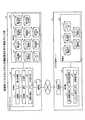
図1は、実施例1にかかるシステムの全体構成例を説明する図である。図1に示すように、このシステムは、異なる地域に設置されたデータセンタが提供するクラウドと、各クラウドを統括的に管理するサーバの一例であるマスタコントローラ30とが、通信可能に接続されて構成される。図1では、一例として、日本、南アメリカ、オーストラリア、フランスの各国に設置されたデータセンタによってクラウドサービス(以下では、クラウドと記載する場合がある)が提供され、日本に設置されたマスタコントローラ30が統括管理する例を説明する。なお、本実施例では、各ゾーンによって提供されるクラウドサービスを狭域クラウド、複数の狭域クラウドを全体とした時のクラウドサービスを広域クラウドと記載する場合がある。[overall structure]
FIG. 1 is a diagram illustrating an overall configuration example of the system according to the first embodiment. As shown in FIG. 1, in this system, clouds provided by data centers installed in different regions and a
ここで、各国には、国や都市などを地域で区別するリージョン名が割与えられている。例えば、日本には、リージョン名として「JP−1」が設定され、南アメリカには、「NA−N1」が設定される。また、各国は、地域等を考慮して複数のデータセンタをグループ化したゾーンを有する。 Here, each country is assigned a region name that distinguishes countries and cities by region. For example, in Japan, "JP-1" is set as the region name, and in South America, "NA-N1" is set. In addition, each country has a zone in which a plurality of data centers are grouped in consideration of regions and the like.
例えば、日本の場合、データセンタDC001とDC002をグループ化したゾーン「JP−W1」と、データセンタDC011とDC012をグループ化したゾーン「JP−E1」とを有する。したがって、ゾーン「JP−W1」では、データセンタDC001とDC002とによって、クラウド環境が提供され、ゾーン「JP−E1」では、データセンタDC011とDC012とによって、クラウド環境が提供される。なお、ゾーン内のデータセンタは同じ地域であることから、料金体系も同じであるとする。また、1つのクラウド環境は、1台のデータセンタで提供することもでき、複数台のデータセンタが連携して提供することもできる。 For example, in the case of Japan, it has a zone "JP-W1" in which data centers DC001 and DC002 are grouped, and a zone "JP-E1" in which data centers DC011 and DC012 are grouped. Therefore, in the zone "JP-W1", the cloud environment is provided by the data centers DC001 and DC002, and in the zone "JP-E1", the cloud environment is provided by the data centers DC011 and DC012. Since the data centers in the zone are in the same area, the charge system is also the same. Further, one cloud environment can be provided by one data center, or can be provided by a plurality of data centers in cooperation with each other.
また、各ゾーンには、各データセンタすなわち各クラウド環境を管理するサーバの一例としてクラウド管理サーバ10が設置される。例えば、日本の場合、ゾーン「JP−W1」とゾーン「JP−E1」とのそれぞれにクラウド管理サーバ10が設置される。なお、ここでは、日本を例に説明したが、各国も同様の構成を有する。また、各国の各クラウド管理サーバも同様の機能を有するので、クラウド管理サーバ10として説明する。 Further, in each zone, a
このようなシステムにおいて、各クラウド管理サーバ10は、各クラウド内での仮想マシン(以下では、VMまたはVMゲストと記載する場合がある)の配備要求に対し、マスタコントローラ30に問い合わせを行う。また、各クラウド管理サーバ10は、問い合わせの応答結果にしたがって、自身が管理する狭域クラウドの環境や広域クラウドの環境を用いてVMゲストを動作させたり、VMゲストを停止させたりする。また、各クラウド管理サーバ10は、自身が管理する狭域クラウドのリソースに関する情報、当該狭域クラウドで動作するVMゲストに関する情報などを定期的に収集して管理する。 In such a system, each
そして、マスタコントローラ30は、各クラウド管理サーバ10から、狭域クラウドのリソースに関する情報やVMゲストに関する情報を収集する。このようなマスタコントローラ30は、異なる地域に設置されたデータセンタが提供する狭域クラウドに関し、各狭域クラウド上でVMゲストを利用する際の電力に関する料金情報を収集する。また、マスタコントローラ30は、各狭域クラウドで動作する各VMゲストに関し、各VMゲストがクラウドに配備されてからの累積時間を取得する。そして、マスタコントローラ30は、各狭域クラウドの料金情報と各VMゲストの累積時間とに基づいて、各VMゲストの移行計画を生成する。 Then, the
例えば、マスタコントローラ30は、相対的に稼働時間が長いVMゲストを相対的に電力料金が安いクラウドに移動させる移動計画と、相対的に稼働時間が短いVMゲストを相対的に電力料金が高いクラウドに移動させる移動計画を生成して、各クラウド管理サーバ10に移動計画を配信する。そして、各クラウド管理サーバ10は、指定されたタイミングや任意のタイミングで、配信された移動計画を実行して、各VMゲストを計画されたクラウドにマイグレーションする。この結果、マスタコントローラ30は、広域クラウド全体でみた時の電力量の偏りを抑制することができ、広域クラウド全体の電力料金を削減することができる。 For example, the
[機能構成]
次に、図2を用いて、各クラウド管理サーバ10とマスタコントローラ30のそれぞれの機能構成について説明する。図2は、実施例1にかかるシステムの機能構成を示す機能ブロック図である。なお、各狭域クラウドの各クラウド管理サーバは、同様の構成を有するので、ここでは、クラウド管理サーバ10として説明する。[Functional configuration]
Next, the functional configurations of the
(クラウド管理サーバ10の機能構成)
図2に示すように、クラウド管理サーバ10は、通信部11と記憶部12と制御部20とを有する。(Functional configuration of cloud management server 10)
As shown in FIG. 2, the
通信部11は、他のクラウド管理サーバ10、各VMゲスト、マスタコントローラ30との間の通信を確立して、各種データ等を送受信する処理部である。例えば、通信部11は、各VMゲストから、VMゲストそれぞれが使用するプロセッサやメモリなどの資源情報を受信し、マスタコントローラ30から、各種要求や移動計画などを受信する。また、通信部11は、各VMゲストにマイグレーション指示を送信し、マスタコントローラ30に各VMゲストの資源情報などの各種情報を送信する。 The communication unit 11 is a processing unit that establishes communication with another
記憶部12は、制御部20が実行するプログラムやデータなどを記憶する記憶装置の一例であり、例えばメモリやハードディスクなどである。この記憶部12は、電力契約情報DB13、電力使用状況DB14、レイテンシDB15、VMリソース管理DB16、DCリソース管理DB17を記憶する。なお、各DBが記憶する情報は、マスタコントローラ30に集約されるので、詳細な説明はマスタコントローラ30の機能構成で説明する。 The
電力契約情報DB13は、クラウド管理サーバ10が管理下におき、クラウドサービスを提供するデータセンタが契約する電気料金に関する情報を記憶するデータベースである。例えば、電力契約情報DB13は、電力会社名、1kWhあたりの料金(従量)、夜間料金や夏季料金などの特別料金などを記憶する。 The power
電力使用状況DB14は、クラウド管理サーバ10が管理する各データセンタで使用される電力量を記憶するデータベースである。例えば、電力使用状況DB14は、一日の総電力量、夜間の電力量、昼間の電力量、ピーク時の電力量などを記憶する。また、電力使用状況DB14は、各日ごとの電力量や各月ごとの電力量などを記憶することもできる。 The power
レイテンシDB15は、各狭域クラウド間のレイテンシを記憶するデータベースである。具体的には、レイテンシDB15は、クラウド管理サーバ10が管理するデータセンタ(DC001とDC002)のそれぞれについて、各国の各データセンタとの間のレイテンシを記憶する。また、レイテンシDB15は、クラウド管理サーバ10が管理する各データセンタが契約する帯域などのネットワーク情報を記憶することもできる。 The
VMリソース管理DB16は、クラウド管理サーバ10が管理する各データセンタで動作する各VMゲストに関する情報を記憶する。例えば、VMリソース管理DB16は、データセンタごとに、起動しているVMゲストを管理する。また、VMリソース管理DB16は、VMゲストごとに、生存時間、稼働時間、使用プロセッサ情報(vCPU(Hz))、使用プロセッサ数(vCPU(個))、使用メモリ容量(メモリ(GB))などのリソース情報を記憶する。 The VM
DCリソース管理DB17は、クラウド管理サーバ10が管理する各データセンタのリソース情報を記憶するデータベースである。例えば、DCリソース管理DB17は、各データセンタについて、各VMゲストに割当て可能な全リソース量および全リソース量のうち実際に使用されているリソース量などを記憶する。 The DC
制御部20は、クラウド管理サーバ10全体を司る処理部であり、例えばプロセッサなどである。この制御部20は、電力情報収集部21、レイテンシ測定部22、稼働情報収集部23、移動実行部24を有する。なお、電力情報収集部21、レイテンシ測定部22、稼働情報収集部23、移動実行部24は、プロセッサなどの電子回路の一例やプロセッサが実行するプロセスの一例などである。 The
電力情報収集部21は、マスタコントローラ30からの指示を受信した場合や定期的なタイミングで、クラウド管理サーバ10が管理する各データセンタについて、契約している電力の料金情報や使用した電力料金等に関する情報を収集する処理部である。 The electric power
例えば、電力情報収集部21は、契約している電力料金に関する情報を管理者等から受け付けて電力契約情報DB13に格納する。また、電力情報収集部21は、各データセンタから時間単位の使用電力量を収集し、収集した使用電力量にしたがって、電力使用状況DB14の各情報を生成して格納する。また、電力情報収集部21は、マスタコントローラからの要求に応じて、電力契約情報DB13に記憶される情報や電力使用状況DB14に記憶される情報を、マスタコントローラ30に送信する。 For example, the electric power
レイテンシ測定部22は、クラウド管理サーバ10が管理する各データセンタと、他のデータセンタとの間のレイテンシを測定する処理部である。例えば、レイテンシ測定部22は、データセンタ(DC001)と他のデータセンタ間のレイテンシを一般的な公知の手法で測定し、レイテンシDB15に格納する。また、レイテンシ測定部22は、マスタコントローラ30からの要求に応じて、レイテンシDB15に記憶される情報を、マスタコントローラ30に送信する。 The
稼働情報収集部23は、管理下のクラウドで動作するVMに関する情報を収集する処理部である。例えば、稼働情報収集部23は、定期的に、データセンタDC001で動作するVMゲストについて、割り当てられた仮想プロセッサのスペックを示す「vCPU(Hz)」、割り当てられた仮想プロセッサの数を示す「vCPU(個)」、割り当てられた仮想メモリの容量を示す「メモリ(GB)」を収集して、VMリソース管理DB16に格納する。さらに、稼働情報収集部23は、各VMについて、クラウドの配備された日付、配備されてからの累積である生存時間(分)、実際に動作している時間の累積である稼働時間(分)などを収集して、VMリソース管理DB16に格納する。また、稼働情報収集部23は、マスタコントローラ30からの要求に応じて、VMリソース管理DB16に記憶される情報を、マスタコントローラ30に送信する。 The operation
さらに、稼働情報収集部23は、管理下のデータセンタのリソースに関する情報を収集する。例えば、稼働情報収集部23は、提供可能な全リソースの合計と、定期的に収集したVMゲストによって使用されている使用リソースとをDCリソース管理DB17に格納する。また、稼働情報収集部23は、全リソース合計から使用リソースを減算して、空きリソースを算出して、DCリソース管理DB17に格納する。また、稼働情報収集部23は、マスタコントローラ30からの要求に応じて、DCリソース管理DB17に記憶される情報を、マスタコントローラ30に送信する。 Further, the operation
(マスタコントローラ30の機能構成)
図2に示すように、マスタコントローラ30は、通信部31と記憶部32と制御部50とを有する。(Functional configuration of master controller 30)
As shown in FIG. 2, the
通信部31は、各クラウド管理サーバ10との間の通信を制御する処理部である。例えば、通信部31は、各クラウド管理サーバ10から、電力情報、VMゲストの稼働情報、データセンタのリソース情報を受信する。また、通信部31は、各クラウド管理サーバ10に、各種要求、VMゲストの移動計画や移動指示などを送信する。 The
記憶部32は、制御部50が実行するプログラムやデータなどを記憶する記憶装置の一例であり、例えばメモリやハードディスクなどである。記憶部32は、拠点情報DB33、電力会社DB34、電力使用実績DB35、電力使用状況DB36、VMリソース管理DB37、DCリソース管理DB38、環境負荷DB39、電力需要予測DB40、レイテンシDB41、帯域管理DB42、移動計画DB43を記憶する。 The
拠点情報DB33は、クラウドを提供するデータセンタが設置されている拠点に関する情報を記憶するデータベースである。図3は、拠点情報DB33に記憶される情報の例を示す図である。図3に示すように、拠点情報DB33は、「拠点情報、契約電力会社情報、国情報」を対応付けて記憶する。なお、ここで記憶される情報は、クラウド管理サーバ10から受信する電力契約情報等を用いて生成することもでき、予め管理者が設定することもできる。 The
ここで記憶される「拠点情報」は、データセンタの設置場所を示す情報であり、「拠点コード、拠点名」が設定される。「拠点コード」は、拠点を識別する識別子であり、「拠点名」は、拠点の名称である。「契約電力会社情報」は、拠点に電力を提供する電力会社の情報であり、「電力会社コード、契約電力(kW)」が設定される。「電力会社コード」は、電力会社を識別する識別子であり、「契約電力(kW)」は、拠点が契約する電力値である。「国情報」は、拠点すなわちデータセンタが設置される国を特定する情報であり、「地域、UTC差」が設定される。「地域」は、国を特定する識別子であり、例えば日本の場合は「JP」、アメリカの場合は「US」などが設定される。「UTC差」は、世界協定時との時差を示す。 The "base information" stored here is information indicating the installation location of the data center, and the "base code and base name" are set. The "base code" is an identifier that identifies the base, and the "base name" is the name of the base. The "contracted electric power company information" is information on the electric power company that provides electric power to the base, and the "electric power company code, contracted electric power (kW)" is set. The "electric power company code" is an identifier that identifies the electric power company, and the "contracted electric power (kW)" is the electric power value contracted by the base. The "country information" is information that identifies the country where the base, that is, the data center is installed, and the "region, UTC difference" is set. The "region" is an identifier that identifies a country. For example, "JP" is set in the case of Japan, and "US" is set in the case of the United States. "UTC difference" indicates the time difference from the time of the World Agreement.
図3の場合、拠点コード「DC001」の拠点名「北海道DC」は、UTC時差が「9時間」である地域「日本(JP)」に設置され、この拠点名「北海道DC」は、電力会社コードが「P05」の電力会社から「1500kW/日」の電力契約を結んでいることを示す。 In the case of FIG. 3, the base name "Hokkaido DC" of the base code "DC001" is installed in the area "Japan (JP)" where the UTC time difference is "9 hours", and this base name "Hokkaido DC" is an electric power company. The code indicates that the power company of "P05" has a power contract of "1500 kW / day".
電力会社DB34は、各データセンタに電力を供給する電力会社に関する情報を記憶する。ここで記憶される情報は、クラウド管理サーバ10から受信する電力契約情報等を用いて生成することもでき、予め管理者が設定することもできる。図4は、電力会社DB34に記憶される情報の例を示す図である。図4に示すように、電力会社DB34は、「国コード、電力会社コード、電力会社名、基本料金単価(kV)、従量、季節料金」を対応付けて記憶する。なお、ここでは一例として単位は円、小数点以下2桁までを利用する。 The electric power company DB 34 stores information about the electric power company that supplies electric power to each data center. The information stored here can be generated using the power contract information or the like received from the
ここで記憶される「国コード」は、国を識別する識別子であり、図3の「地域」と同様である。「電力会社コード」は、図3と同様であり、「電力会社名」は、電力会社の名称である。「基本料金単価」は、1kVあたりの電力量の単価である。「従量」は、1kWあたりの従量制の料金を示し、「ピーク時、昼間、夜間」に分けて設定される。「ピーク時」は、13時から16時までの電力料金であり、「昼間」は、8時から22時までの電力料金であり、「夜間」は、22時から8時までの電力料金である。なお、基本料金は、金料金単価×契約電力×力率(割引や割増)で算出され、ピーク時の設定がない場合は昼間と同じ料金を設定する。「季節料金」は、特別な期間のときだけに設定される特別料金であり、例えば「夏季料金」などの季節料金などである。この「夏季料金」は、開始から終了までの間は、従量に変えて、特別に設定された料金が使用される。 The "country code" stored here is an identifier that identifies the country, and is the same as the "region" in FIG. The "electric power company code" is the same as in FIG. 3, and the "electric power company name" is the name of the electric power company. The "basic charge unit price" is the unit price of electric energy per 1 kV. "Measured amount" indicates a metered rate per 1 kW, and is set separately for "peak time, daytime, and nighttime". "Peak time" is the electricity charge from 13:00 to 16:00, "daytime" is the electricity charge from 8:00 to 22:00, and "nighttime" is the electricity charge from 22:00 to 8:00. is there. The basic charge is calculated as gold charge unit price x contract power x power factor (discount or premium), and if there is no peak setting, the same charge as in the daytime is set. The "seasonal charge" is a special charge set only during a special period, and is, for example, a seasonal charge such as a "summer charge". From the start to the end of this "summer charge", a specially set charge is used instead of a pay-as-you-go rate.
図4の1行目は、日本に設置された「P01」の〇電力会社の基本料金単価が「1522.80kV」であることを示す。また、この〇電力会社は、ピーク時は1kWあたり「16.87円」、昼間時は1kWあたり「15.09円」、夜間時は1kWあたり「11.85円」の従量課金を行う。さらに、この〇電力会社は、「7月1日」から「9月30日」までの間は、夏季料金として、時間帯に関係なく、1kWあたり「16.00円」の従量課金を行う。 The first line of FIG. 4 shows that the basic charge unit price of the electric power company of "P01" installed in Japan is "1522.80 kV". In addition, this electric power company charges a pay-as-you-go rate of "16.87 yen" per 1 kW during peak hours, "15.09 yen" per 1 kW during the daytime, and "11.85 yen" per 1 kW during the nighttime. Furthermore, from "July 1st" to "September 30th", this electric power company will charge "16.00 yen" per kW as a summer charge regardless of the time of day.
電力使用実績DB35は、各データセンタごとに一日の電力使用状況を記憶するデータベースである。ここで記憶される情報は、クラウド管理サーバ10から受信する電力契約情報等を用いて生成することができる。図5は、電力使用実績DB35に記憶される情報の例を示す図である。図5に示すように、電力使用実績DB35は、「拠点コード、Today電力量(kW)、夜間(00〜08)、昼間(08〜13)、ピーク時(13〜16)、昼間(16〜22)、夜間(22〜24)、余裕電力、契約電力」を対応付けて記憶する。 The power
ここで記憶される「拠点コード」は、図3等と同様であり、「Today電力量」は、一日の総使用電力量である。「夜間(00〜08)」は、0時から8時までに使用された電力量であり、「昼間(08〜13)」は、8時から13時までに使用された電力量であり、「ピーク時(13〜16)」は、13時から16時までに使用された電力量であり、「昼間(16〜22)」は、16時から22時までに使用された電力量であり、「夜間(22〜24)」は、22時から24時までに使用された電力量である。「余裕電力」は、使用可能な電力であり、契約電力に到達するまでの残りの電力量である。「契約電力」は、一日で使用可能な電力量の上限値である。 The "base code" stored here is the same as in FIG. 3 and the like, and the "Today electric energy" is the total daily electric energy used. "Night (00 to 08)" is the amount of electric power used from 0:00 to 8:00, and "daytime (08 to 13)" is the amount of electric power used from 8:00 to 13:00. "Peak time (13 to 16)" is the amount of power used from 13:00 to 16:00, and "daytime (16 to 22)" is the amount of power used from 16:00 to 22:00. , "Night (22-24)" is the amount of electric power used from 22:00 to 24:00. The "margin power" is the power that can be used and is the amount of power remaining until the contract power is reached. "Contract power" is the upper limit of the amount of power that can be used in one day.
図5の1行目では、拠点コード「DC001」のデータセンタは、一日の電力量の契約が「1500.00kWh」で、一日の使用電力量が「1370.00kWh」であり、「130.00kWh」の余裕があることを示している。また、当該データセンタは、0時から8時までの間は「200.00kWh」を使用し、8時から13時までの間は「150.00kWh」を使用し、13時から16時までの間は「800.00kWh」を使用し、16時から22時までの間は「180.00kWh」を使用し、22時から24時までの間は「40.00kWh」を使用したことが示される。なお、ここで記憶される情報は、数日の平均値でよく、各日のデータであってもよい。 In the first line of FIG. 5, the data center of the base code "DC001" has a daily electric energy contract of "1500.00kWh", a daily electric energy consumption of "1370.00kWh", and "130". It shows that there is a margin of "0.00kWh". In addition, the data center uses "200.00kWh" from 0:00 to 8:00, "150.00kWh" from 8:00 to 13:00, and from 13:00 to 16:00. It is shown that "800.00kWh" was used during the period, "180.00kWh" was used between 16:00 and 22:00, and "40.00kWh" was used between 22:00 and 24:00. .. The information stored here may be an average value of several days, or may be data of each day.
電力使用状況DB36は、各データセンタについて、一日の各時間における使用電力量を記憶する。ここで記憶される情報は、クラウド管理サーバ10から受信する情報にしたがって生成することもでき、予め管理者が設定することもできる。図6は、電力使用状況DB36に記憶される情報の例を示す図である。図6に示すように、電力使用状況DB36は、「拠点コード、年月日、1時間おきの時間帯、電力量(kWh)」を対応付けて記憶する。 The power
ここで記憶される「拠点コード」は、図3と同様であり、「年月日」は、電力量データの日付である。「0から23」は、一日を1時間おきにグループ化したものであり、「電力量」は、一日の総使用電力量である。図6の例では、拠点コード「DC001」のデータセンタについて、「2015年8月1日」から「2015年8月10日」の各日の各時間帯の使用電力量を示している。 The "base code" stored here is the same as in FIG. 3, and the "date" is the date of the electric energy data. “0 to 23” is a grouping of days every hour, and “electric energy” is the total electric energy used in a day. In the example of FIG. 6, for the data center of the base code “DC001”, the electric energy used in each time zone of each day from “August 1, 2015” to “August 10, 2015” is shown.
VMリソース管理DB37は、各クラウドで動作する各VMに関する情報を記憶するデータベースである。ここで記憶される情報は、クラウド管理サーバ10から受信する情報にしたがって生成することができる。図7は、VMリソース管理DB37に記憶される情報の例を示す図である。図7に示すように、VMリソース管理DB37は、VMゲスト毎のリソース管理表とDC別のVMリソース集計表を記憶する。 The VM
VMゲスト毎のリソース管理表は、「VMゲスト名、配備日、生存時間、稼働時間、vCPU(GHz)、vCPU(個)、メモリ(GB)」を対応付けて管理する。「VMゲスト名」は、VMゲストを識別する識別子であり、「配備日」は、VMゲストがクラウドに配備された年月日である。「生存時間」は、VMゲストが配備されてから現在までの累積時間であり、「稼働時間」は、VMゲストが実際に稼働している累積時間である。「vCPU(GHz)、vCPU(個)、メモリ(GB)」は、VMゲストが使用するリソース情報であり、「vCPU(GHz)」はVMゲストが使用する仮想プロセッサのスペックであり、「vCPU(個)」はVMゲストが使用する仮想プロセッサの数であり、「メモリ(GB)」はVMゲストが使用するメモリの容量である。 The resource management table for each VM guest is managed in association with "VM guest name, deployment date, survival time, operating time, vCPU (GHz), vCPU (pieces), memory (GB)". The "VM guest name" is an identifier that identifies the VM guest, and the "deployment date" is the date when the VM guest was deployed in the cloud. The "survival time" is the cumulative time from the deployment of the VM guest to the present, and the "operating time" is the cumulative time during which the VM guest is actually operating. "VCPU (GHz), vCPU (pieces), memory (GB)" is resource information used by the VM guest, and "vCPU (GHz)" is the specifications of the virtual processor used by the VM guest, and "vCPU ( “)” Is the number of virtual processors used by the VM guest, and “memory (GB)” is the amount of memory used by the VM guest.
図7の例では、VMゲスト名「VM001」のVMが2015年6月15日に、2GHzの仮想プロセッサ2個と16GBのメモリ容量を割与えられて、クラウドに配備され、配備されてから371520分が経過し、そのうち124320分稼働していることを示す。 In the example of FIG. 7, the VM with the VM guest name "VM001" was allocated to the cloud with two 2 GHz virtual processors and 16 GB of memory capacity on June 15, 2015, and was deployed in the cloud. Indicates that minutes have passed, of which 124320 minutes have been in operation.
DC別のVMリソース集計表は、「拠点コード、VMゲスト名、生存時間、稼働時間、vCPU(GHz)、vCPU(個)、メモリ(GB)」を対応付けて管理する。各項目は、上述したので詳細な説明は省略する。図7の場合、拠点コード「DC001」のデータセンタにおいてVM001のVMゲストが動作していることを示す。 The VM resource summary table for each DC is managed in association with "base code, VM guest name, survival time, operating time, vCPU (GHz), vCPU (pieces), memory (GB)". Since each item has been described above, detailed description thereof will be omitted. In the case of FIG. 7, it is shown that the VM guest of VM001 is operating in the data center of the base code “DC001”.
DCリソース管理DB38は、各データセンタのリソースに関する情報を記憶するデータベースである。ここで記憶される情報は、クラウド管理サーバ10から受信する情報にしたがって生成することができる。図8は、DCリソース管理DB38に記憶される情報の例を示す図である。図8に示すように、DCリソース管理DB38は、DC毎のリソース集計表を記憶する。 The DC
DC毎のリソース集計表は、各データセンタ(DC)について、リソースの使用状況および他クラウドからの移入可能なリソース量を記憶する。具体的には、DC毎のリソース集計表は、「拠点コード、全リソース合計、空きリソース量、移動不可リソース量、移入可能なリソース量」を管理する。ここで記憶される「拠点コード」は、図3等と同様であり、「全リソース合計」は、DCがVMゲストに提供可能なリソースの合計である。「空きリソース量」は、DC内で未使用のリソース量であり、「移動不可リソース量」は、他のクラウドへ移動することができないVMゲストが使用するリソース量である。「移入可能なリソース量」は、当該DCが移動可能な(受け入れ可能な)リソース量である。なお、各リソース量は、vCPU(GHz)、vCPU(個)、メモリ(GB)で表される。 The resource summary table for each DC stores the resource usage status and the amount of resources that can be imported from other clouds for each data center (DC). Specifically, the resource summary table for each DC manages "base code, total resources, free resource amount, immovable resource amount, transferable resource amount". The "base code" stored here is the same as in FIG. 3, and the "total resources" is the total resources that the DC can provide to the VM guest. The "free resource amount" is the amount of unused resources in the DC, and the "immovable resource amount" is the amount of resources used by the VM guest who cannot move to another cloud. The “importable resource amount” is the amount of resources that the DC can move (accept). Each resource amount is represented by vCPU (GHz), vCPU (pieces), and memory (GB).
環境負荷DB39は、クラウドに存在する全VMゲストに関し、生存時間、稼働時間、割当リソースについて集計した情報を記憶するデータベースである。図9は、環境負荷DB39に記憶される情報の例を示す図である。図9に示すように環境負荷DB39は、「リージョン名、ゾーン名、VMゲスト名、配備日、生存時間、稼働時間、vCPU(GHz)、vCPU(個)、メモリ(GB)、リソース負荷指標」を対応付けて記憶する。「リージョン名」は、国や都市などの地域を識別する識別子であり、「ゾーン名」は、地域等を考慮して複数のデータセンタをグループ化したものを識別する識別子であり、「リソース負荷指標」は、VMのリソース負荷を示した情報であり、「vCPU(GHz)、vCPU(個)、メモリ(GB)」を乗算した指標である。なお、他の項目は、上述しているので説明を省略する。 The
図9の例では、VMゲスト「VM001」がリージョン「SA−1」のゾーン「SA−N1」のクラウドに「2015年6月15日」に配備されたことを示す。また、このVMゲスト「VM001」には、2GHzの仮想プロセッサ2個と16GBのメモリ容量を割与えられており、移動させるのにかかる負荷が「64」である。また、このVMゲスト「VM001」は、クラウドに配備されてから371520分が経過し、そのうち124320分稼働していることを示す。 In the example of FIG. 9, it is shown that the VM guest “VM001” was deployed on “June 15, 2015” in the cloud of the zone “SA-N1” of the region “SA-1”. Further, the VM guest "VM001" is assigned two 2 GHz virtual processors and a memory capacity of 16 GB, and the load required to move the VM guest "VM001" is "64". In addition, this VM guest "VM001" indicates that 371520 minutes have passed since it was deployed in the cloud, and 124320 minutes of it has been in operation.
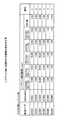
電力需要予測DB40は、データセンタ内の時間帯ごとの電力の需要予測と移入可能な電力量を記憶するデータベースである。ここで記憶される情報は、クラウド管理サーバ10から受信する情報にしたがって格納および生成することができる。図10は、電力需要予測DB40に記憶される情報の例を示す図である。図10に示すように、電力需要予測DB40は、「拠点コード、予測電力量(kWh)、夜間(00〜08)、昼間(08〜13)、ピーク時(13〜16)、昼間(16〜22)、夜間(22〜24)、余裕電力、契約電力、移入可能電力量」を対応付けて記憶する。 The electric power
ここで記憶される拠点コードは、図3等と同様である。夜間(00〜08)は、0時から8時の間で必要になると予測される電力量であり、例えばデータセンタ(DC001)で動作する各VMが0時から8時の間で利用する電力量の合計値以上が設定される。同様に、昼間(08〜13)は、8時から13時の間で必要になると予測される電力量であり、ピーク時(13〜16)は、13時から16時の間で必要になると予測される電力量であり、昼間(16〜22)は、16時から22時の間で必要になると予測される電力量であり、夜間(22〜24)は、22時から24時の間で必要になると予測される電力量である。予測電力量は、夜間(00〜08)、昼間(08〜13)、ピーク時(13〜16)、昼間(16〜22)、夜間(22〜24)を合計した電力量である。契約電力量は、データセンタが契約する電力量の上限値である。余裕電力量は、契約電力量から予測電力量を減算した電力量である。移入可能電力量は、余裕電力量やピーク時の電力量等を用いて制御部50によって算出された、データセンタが受け入れ可能な電力量である。 The base code stored here is the same as in FIG. Nighttime (00 to 08) is the amount of power expected to be required between 0:00 and 8:00, for example, the total value of the amount of power used by each VM operating in the data center (DC001) between 0:00 and 8:00. The above is set. Similarly, the daytime (08-13) is the amount of power expected to be needed between 8:00 and 13:00, and the peak time (13-16) is the amount of power predicted to be needed between 13:00 and 16:00. It is the amount of electric energy that is expected to be required between 16:00 and 22:00 during the daytime (16 to 22), and is expected to be required between 22:00 and 24:00 during the nighttime (22 to 24). The amount. The predicted electric energy is the total electric energy of nighttime (00 to 08), daytime (08 to 13), peak time (13 to 16), daytime (16 to 22), and nighttime (22 to 24). The contracted electric energy is the upper limit of the electric energy contracted by the data center. The spare electric energy is the electric energy obtained by subtracting the predicted electric energy from the contracted electric energy. The transferable electric energy is an electric energy that can be accepted by the data center, which is calculated by the
図10の1行目は、拠点コード「DC001」のデータセンタについての電力需要予測であり、夜間(00〜08)に200kWh、昼間(08〜13)に150kWh、ピーク時(13〜16)に800kWh、昼間(16〜22)に180kWh、夜間(22〜24)に40kWhであり、一日の合計電力量が1370kWhであると予測されることを示す。また、拠点コード「DC001」のデータセンタは、契約電力量が1500kWhであり、余裕電力量が130kWhであり、移入可能電力量として130kWhが算出されたことを示す。 The first line of FIG. 10 is a power demand forecast for a data center having a base code "DC001", which is 200 kWh at night (00 to 08), 150 kWh during the day (08 to 13), and during peak hours (13 to 16). It is 800kWh, 180kWh in the daytime (16-22) and 40kWh in the nighttime (22-24), indicating that the total daily power consumption is predicted to be 1370kWh. Further, the data center of the base code "DC001" indicates that the contracted electric energy is 1500 kWh, the marginal electric energy is 130 kWh, and 130 kWh is calculated as the transferable electric energy.
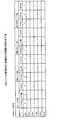
レイテンシDB41は、データセンタごとに、データセンタ間のレイテンシを記憶するデータベースである。ここで記憶される情報は、例えば各データセンタのクラウド管理サーバ10が、他のクラウドのデータセンタに存在するクラウド管理サーバ10に対して測定したレイテンシや各データセンタ内の特定のサーバ間で測定したレイテンシなどである。 The
図11は、レイテンシDB41に記憶される情報の例を示す図である。図11に示すように、レイテンシDB41は、「拠点コード、Destination、レイテンシ測定結果、順位」を対応付けて記憶する。「拠点コード」は、図3と同様であり、「Destination」は、レイテンシの測定先を特定する情報である。「レイテンシ測定結果」は、「midnight(00〜08)、morninng(08〜12)、afternoon(12〜17)、evening(17〜22)、midnight(22〜24)、UTC差」を対応付けて管理する。 FIG. 11 is a diagram showing an example of information stored in the
「midnight(00〜08)」は、0時から8時の間で測定されたレイテンシであり、「morninng(08〜12)」は、8時から12時の間で測定されたレイテンシであり、「afternoon(12〜17)」は、12時から17時の間で測定されたレイテンシであり、「evening(17〜22)」は、17時から22時の間で測定されたレイテンシであり、「midnight(22〜24)」は、22時から24時の間で測定されたレイテンシであり、「UTC差」は、図3と同様である。「順位」は、レイテンシに基づいて移動先として推奨される順位であり、レイテンシが小さいほど上位となる。 "Midnight (00-08)" is the latency measured between 0:00 and 8:00, and "morning (08-12)" is the latency measured between 8:00 and 12:00, and "afternoon (12)". "~ 17)" is the latency measured between 12:00 and 17:00, and "evening (17-22)" is the latency measured between 17:00 and 22:00, "midnight (22-24)". Is the latency measured between 22:00 and 24:00, and the "UTC difference" is the same as in FIG. The "rank" is a rank recommended as a destination based on the latency, and the smaller the latency, the higher the rank.
図11の例は、「DC001」と他の各DCとのレイテンシの測定結果を示している。図11の例は、「DC001」と「DC001」から「DC006」の各レイテンシにしたがって、「DC005」、「DC006」、「DC002」、「DC004」、「DC001」、「DC003」の順で移動先を決定することを示す。また、「DC001」と「DC005」との間では、「midnight(00〜08)、morninng(08〜12)、afternoon(12〜17)、evening(17〜22)、midnight(22〜24)」のそれぞれにおけるレイテンシが「1msec」であり、UTC差が「−1時間」であることを示す。なお、レイテンシが同じ場合は、UTC差が小さいDCを優先する。 The example of FIG. 11 shows the measurement result of the latency between "DC001" and each of the other DCs. In the example of FIG. 11, the movement is performed in the order of "DC005", "DC006", "DC002", "DC004", "DC001", and "DC003" according to the latencies of "DC001" and "DC001" to "DC006". Indicates to decide ahead. Further, between "DC001" and "DC005", "midnight (00 to 08), morning (08 to 12), afternoon (12 to 17), evening (17 to 22), midnight (22 to 24)" The latency in each of the above is "1 msec", and the UTC difference is "-1 hour". If the latencies are the same, priority is given to DC having a small UTC difference.
帯域管理DB42は、各データセンタが契約するネットワークに関する情報を記憶するデータベースである。ここで記憶される情報は、クラウド管理サーバ10から受信する情報にしたがって生成することもでき、予め管理者が設定することもできる。 The
図12は、帯域管理DB42に記憶される情報の例を示す図である。図12に示すように、帯域管理DB42は、「拠点コード、帯域諸元(契約帯域(Gbps)、使用帯域(Gbps)、最大使用帯域(Gbps))を対応付けて記憶する。「拠点コード」は、図3と同様である。「契約帯域」は、データセンタが契約する帯域幅を示し、「使用帯域」は、データセンタが実際に使用する帯域幅を示し、「最大使用帯域」は、過去に使用した最大の帯域幅を示す。図12の例では、拠点コード「DC001」のデータセンタは、100Gbpsの帯域を契約し、一般的には70Gbpsを使用しているが、最大で90Gbpsを使用したことがあることを示す。 FIG. 12 is a diagram showing an example of information stored in the
移動計画DB43は、後述する制御部50によって生成されたVMゲストの移動計画を記憶するデータベースである。図13は、移動計画DB43に記憶される情報の例を示す図である。図13に示すように、移動計画DB43は、「移動対象VM、移動先DC、移動予定日時」を対応付けて記憶する。 The
「移動対象VM」は、移動対象のVMゲストを特定する情報であり、「リージョン名、ゾーン名、拠点コード、VMゲスト名」で特定される。「移動先DC」は、移動的のデータセンタを特定する情報であり、「リージョン名、ゾーン名、拠点コード」で特定される。「移動予定日時」は、VMの移動実行予定を示す情報である。図13の例では、2016年8月15日、リージョン名「SA−1」のゾーン名「SA−N1」の拠点コード「DC001」のクラウドで動作する「VM001」を、リージョン名「NA−N1」のゾーン名「NA−W1」の拠点コード「DCN01」のクラウド(データセンタ)に移動させることが計画されていることを示す。 The "movement target VM" is information for identifying the movement target VM guest, and is specified by the "region name, zone name, base code, VM guest name". The "destination DC" is information that identifies a mobile data center, and is specified by a "region name, zone name, base code". The "scheduled move date and time" is information indicating the move execution schedule of the VM. In the example of FIG. 13, on August 15, 2016, "VM001" operating in the cloud of the base code "DC001" of the zone name "SA-N1" of the region name "SA-1" is changed to the region name "NA-N1". It indicates that it is planned to move to the cloud (data center) of the base code "DCN01" of the zone name "NA-W1".
制御部50は、マスタコントローラ30全体を司る処理部であり、例えばプロセッサなどである。この制御部50は、収集部51、電力計画部52、管理部53、配備部54、移動計画部55、計画実行部56を有する。なお、収集部51、電力計画部52、管理部53、配備部54、移動計画部55、計画実行部56は、プロセッサなどの電子回路の一例やプロセッサが実行するプロセスの一例などである。 The
収集部51は、クラウド全体の電力状況を取得する処理部である。具体的には、収集部51は、定期的に、狭域クラウドを形成する各データセンタから、契約電力、電力の使用実績、日ごとの電力使用状況などを取得する。例えば、収集部51は、月に1回、各クラウド管理サーバ10から契約電力会社の情報を取得して、拠点情報DB33に格納する。同様に、収集部51は、定期的に、各国の電力会社から、電力料金や従量や季節料金などを取得して、電力会社DB34に格納する。 The
また、収集部51は、1時間ごとに、各データセンタから電力の使用状況を取得して、1時間ごとの電力状況を記憶する電力使用状況DB36に格納する。そして、収集部51は、1日の電力使用状況が収集されると、データセンタごとの1日の電力使用状況を生成して、電力使用実績DB35に格納する。 Further, the collecting
電力計画部52は、各データセンタの電力の使用状況から、電力需要予測を実行する処理部である。具体的には、電力計画部52は、各クラウドの現在の電力需要と過去の履歴を定期的に取得し、ピーク時間帯に、各クラウドで契約電力を超えない、かつ目標削減量を満足するように、クラウド間での電力需要を計画する。ここでは、順位付けと電力需要計画について説明する。 The
(順位付け)
例えば、電力計画部52は、拠点情報DB33を参照して、各データセンタが利用する電力会社を特定し、特定した電力会社の電力料金を、電力会社DB34を参照して特定する。続いて、電力計画部52は、各データセンタについて、特定した電力料金と電力使用状況DB36に記憶される1日の電力使用量とを用いて、1日の電力料金を算出する。例えば、電力計画部52は、基本料金と従量課金とを算出し、これらの合計値を電力料金として算出する。なお、基本料金は、基本料金単価×契約電力×力率で算出される。従量課金は、各時間帯の電力使用量に、各時間帯に設定される料金単価を乗算して算出される。このとき、電力計画部52は、夏季料金に該当する場合は、従量課金に夏季料金を用いることもできる。(Ranking)
For example, the electric
そして、電力計画部52は、算出した各データセンタの一日の電力料金(基本料金+従量課金)の安い順に順位付けを行い、安い順で、電力使用実績DB35に記憶される情報を並び替える。なお、この手法に限定されず、電力計画部52は、各データセンタの基本料金の安い順に並び替えてもよい。 Then, the
(電力需要計画)
例えば、電力計画部52は、各データセンタの電力需要について、現状の電力量と過去の電力量より、ピーク時を考慮した今後の需要予測を行う。具体的には、電力計画部52は、電力計画部52によって生成された電力使用実績DB35に記憶される各データセンタについて、使用電力量が契約電力量に到達するまでの残りの電力量(余裕電力量)を算出する。まず、電力計画部52は、夜間、昼間、ピーク時のそれぞれを合計して一日の使用電力量(Today電力量)を算出し、契約電力からToday電力量を減算して余裕電力量を算出して、電力使用実績DB35に格納する。(Electricity demand plan)
For example, the electric
続いて、電力計画部52は、各データセンタについて、受け入れ可能な電力量である移入可能電力量を算出する。例えば、電力計画部52は、契約電力からToday電力量を減算して、移入可能電力量を算出する。なお、データセンタには、非常時や緊急時のサーバ起動等に備えて、予め所定の電力量(確保電力量)を確保することもある。したがって、電力計画部52は、そのようなデータセンタについては、契約電力からToday電力量および確保電力量を減算して移入可能電力量を算出することもできる。 Subsequently, the
そして、電力計画部52は、各データセンタについて、電力使用実績DB35に記憶される「Today電力量」を「予測電力量」として抽出するとともに、電力使用実績DB35に記憶される「夜間(00〜08)、昼間(08〜13)、ピーク時(13〜16)、昼間(16−22)、夜間(22〜24)、契約電力」、算出した「移入可能電力量」を対応付けて、電力需要予測DB40に格納する。このようにすることで、各データセンタの電力需要が予測でき、各データセンタが移入可能な電力量が特定される。 Then, the electric
図2に戻り、管理部53は、各クラウドで動作するVMの情報、各クラウドを提供するデータセンタのリソース情報、各データセンタが利用するネットワーク情報、各データセンタ間のレイテンシなどを定期的に収集して管理する処理部である。 Returning to FIG. 2, the management unit 53 periodically obtains information on the VM operating in each cloud, resource information on the data center that provides each cloud, network information used by each data center, latency between each data center, and the like. It is a processing unit that collects and manages.
(VMリソース)
例えば、管理部53は、各クラウド管理サーバ10から、クラウド上で動作するVMゲストが使用するリソース情報(vCPU(GHz)、vCPU(個)、メモリ(GB))と生存時間と稼働時間とクラウドへの配備日を取得する。そして、管理部53は、取得したこれらの情報を、VMリソース管理DB37のVM毎のVMリソース集計表に格納する。また、管理部53は、取得したこれらの情報と、クラウド管理サーバ10が管理するデータセンタの拠点コードとを対応付けて、VMリソース管理DB37のDC別のVMリソース集計表に格納する。(VM resource)
For example, the management unit 53 receives resource information (vCPU (GHz), vCPU (pieces), memory (GB)), survival time, operating time, and cloud used by VM guests operating on the cloud from each
(環境負荷情報)
管理部53は、各VMゲストについて、リソース情報の各項目(vCPU(GHz)、vCPU(個)、メモリ(GB))を乗算して、リソース負荷指標を算出する。また、管理部53は、各クラウド管理サーバ10から、各VMゲストが動作するリージョン名およびゾーン名を取得する。そして、管理部53は、リージョン名、ゾーン名、VMゲスト名、配備日、VMゲストのリソース情報、生存時間、稼働時間、リソース負荷指標を対応付けて、環境負荷DB39に格納する。(Environmental load information)
The management unit 53 calculates a resource load index by multiplying each item of resource information (vCPU (GHz), vCPU (pieces), memory (GB)) for each VM guest. In addition, the management unit 53 acquires the region name and zone name in which each VM guest operates from each
(DCリソース)
管理部53は、各クラウド管理サーバ10から、データセンタの全リソースの合計、移動不可リソース量を取得する。また、管理部53は、各データセンタについて、全リソースの合計から、移動不可リソース量とVMゲストのリソース量とを除いた空きリソース量を算出する。なお、一般的には、この空きリソース量を、データセンタへ移行可能なリソース量である移入可能なリソース量とすることができるが、データセンタには、非常時や緊急時のVMゲスト起動等に備えて、予め所定のリソース量(確保リソース量)を確保する必要があることもある。したがって、管理部53は、そのようなデータセンタについては、全リソースの合計から、移動不可リソース量とVMゲストのリソース量に加えてさらに確保リソース量を減算して空きリソース量を算出することもできる。そして、管理部53は、クラウド管理サーバ10が管理するデータセンタの拠点コードと、空きリソース量と移動不可リソース量と移入可能なリソース量とを対応付けて、DCリソース管理DB38に格納する。(DC resource)
The management unit 53 acquires the total of all resources of the data center and the amount of immovable resources from each
(帯域)
管理部53は、各クラウド管理サーバ10から、各データセンタ(拠点)の帯域諸元を取得する。そして、管理部53は、拠点コードと帯域諸元とを対応付けて、帯域管理DB42に格納する。(Band)
The management unit 53 acquires the bandwidth specifications of each data center (base) from each
(レイテンシ)
管理部53は、各クラウド管理サーバ10から、各クラウド管理サーバ10が管理する各データセンタ(拠点)と他のデータセンタとの間のレイテンシ測定結果を取得する。ここで取得されるレイテンシ測定結果は、予め指定されたmidnightなどの各時間帯で測定された測定結果であり、測定元と測定先のUTC差を含む。そして、管理部53は、測定元のデータセンタごとに、測定先のデータセンタを示す「Destination」とレイテンシ測定結果とを対応付けて、レイテンシDB41に格納する。また、管理部53は、レイテンシDB41において、データセンタ間のレイテンシが小さい順に、順位付けを行う。なお、順位付けは、レイテンシ測定結果の平均値を比較する。(Latency)
The management unit 53 acquires the latency measurement result between each data center (base) managed by each
図2に戻り、配備部54は、クラウド管理サーバ10から、新規VMゲストの配備要求を受け付けた場合に、配備先を決定してクラウド管理サーバ10に通知する処理部である。具体的には、配備部54は、各クラウドについて、現在の電力需要と過去の履歴を定期的にチェックし、ピーク時間帯に、各クラウドで契約電力を超えない、かつ目標削減量を満足するように、新規VMを配備する。 Returning to FIG. 2, the
例えば、配備部54は、クラウド管理サーバ10から、起動対象のVMゲストのリソース情報、稼働時間帯と稼働時間を含む配備要求を受信する。すると、配備部54は、vCPUやメモリに対して予め設定されている単位時間当たりの電力量を用いて、配備対象のVMゲストの予想電力量を算出する。そして、配備部54は、電力需要予測DB40に記憶されるデータセンタ(拠点コード)を上から参照して、ピーク時の電力が閾値未満で、配備対象のVMゲストの予想電力量以上の移入可能電力量を有するとともに起動対象のVMゲストのリソース量を確保できるデータセンタを、配備先に指定する応答をクラウド管理サーバ10に送信する。クラウド管理サーバ10は、この応答で特定されるデータセンタに、VMゲストの配備指示を送信する。 For example, the
このとき、配備部54は、レイテンシを考慮することもできる。例えば、配備部54は、配備要求を送信したクラウド管理サーバ10が管理するデータセンタとの間のレイテンシが所定値以下のデータセンタを配備先対象として絞り込む。そして、配備部54は、絞り込んだデータセンタのうち、配備対象のVMゲストの予想電力量以上の移入可能電力量を有するデータセンタを、配備先に指定することもできる。 At this time, the
そして、配備部54は、クラウド管理サーバ10によるVMゲストの配備が行われると、各クラウド管理サーバ10にリソース情報等の収集を要求し、収集部51や管理部53に収集指示を送信する。この結果、収集部51や管理部53は、クラウド管理サーバ10から各種情報を収集して、各種DBを更新する。 Then, when the VM guest is deployed by the
また、配備部54は、配備要求を送信したクラウド管理サーバ10の管理下にあるデータセンタに優先的に配備することもできる。このとき、配備部54は、新規VMゲストを当該データセンタに配備することで、予想電力量が超える場合に、上記手法を用いて配備先のクラウドを決定することもできる。 Further, the
図14は、VMゲストの配備時の制御を説明する図である。図14では、リージョンAのクラウドAのデータセンタからVMゲストの配備要求が送信された例で説明する。図14の左図に示すように、マスタコントローラ30は、新規配備時はリージョンAのクラウドAの電力実績に余裕があるが、過去の実績を参照することで、新たなVMゲストが起動すると、数時間後に目標電力を超えると判定する。これに対して、図14の右図に示すように、マスタコントローラ30は、リージョンBのクラウドBについては、過去の実績を参照すると、新たなVMゲストが起動した後も目標電力を超えないと判定する。このような場合、配備部54は、クラウド管理サーバ10に、新規配備の要求元であるリージョンAのクラウドAではなく、リージョンBのクラウドBに配備先を変更する指示を送信する。なお、目標電力とは、データセンタに設定された使用電力の上限値であり、契約電力と同じであってもよい。 FIG. 14 is a diagram illustrating control during deployment of the VM guest. FIG. 14 describes an example in which a VM guest deployment request is transmitted from the cloud A data center in region A. As shown in the left figure of FIG. 14, the
移動計画部55は、各クラウドの料金情報と各VMの生存時間とに基づいて、各VMの移行計画を生成する処理部である。具体的には、移動計画部55は、定期的に、各DBを参照して、生存時間が相対的に長いVMを電力料金が相対的に高いクラウドに移行し、生存時間が相対的に短いVMを電力料金が相対的に安いクラウドに移行する移行計画を生成する。 The movement planning unit 55 is a processing unit that generates a migration plan for each VM based on the charge information of each cloud and the survival time of each VM. Specifically, the movement planning unit 55 periodically refers to each DB to move a VM having a relatively long survival time to a cloud having a relatively high power charge, and the survival time is relatively short. Generate a migration plan to move VMs to the cloud, where electricity charges are relatively low.
より詳細には、移動計画部55は、電力コストが高いクラウドAから電力コストが安いクラウドBへの移動を判断する際に、対象のVMゲストXとVMゲストYについて、以下の比較を行う。(1)VMゲストXより生存時間が短く、その資源量が小さいVMゲスY、(2)VMゲストXより生存時間が短く、その資源量が大きいVMゲストY、(3)VMゲストXより生存時間が長く、その資源量が小さいVMゲストY、(4)VMゲストXより生存時間が長く、その資源量が大きいVMゲストY。ここで、VMゲストXよりもVMゲストYの方が生存時間が短いとき、VMゲストYの環境負荷が低いと判断され、VMゲストXよりもVMゲストYの方が資源量が小さいときは、VMゲストYの環境負荷が低いと判断される。クラウドでは頻繁にVMゲストの作成や削除が行われるので、生存時間が短いものは削除される可能性が高いと判断する。つまり、長く存在し資源量が大きいもの程、コストが安いクラウドへ動かす効果があると判断する。 More specifically, the movement planning unit 55 makes the following comparisons with respect to the target VM guest X and VM guest Y when determining the movement from the cloud A having a high power cost to the cloud B having a low power cost. (1) VM Guess Y, which has a shorter survival time and smaller resource amount than VM Guest X, (2) VM Guest Y, which has a shorter survival time and larger resource amount than VM Guest X, and (3) Survival than VM Guest X. A VM guest Y that has a long time and a small amount of resources, and (4) a VM guest Y that has a longer survival time and a larger amount of resources than the VM guest X. Here, when the survival time of the VM guest Y is shorter than that of the VM guest X, it is determined that the environmental load of the VM guest Y is low, and when the resource amount of the VM guest Y is smaller than that of the VM guest X, It is judged that the environmental load of VM guest Y is low. Since VM guests are frequently created and deleted in the cloud, it is judged that those with a short survival time are likely to be deleted. In other words, it is judged that the longer it exists and the larger the amount of resources, the more effective it is to move to the cloud where the cost is cheaper.
図15は、定期的なVMゲストの移動計画を説明する図である。図15では、リージョンAのクラウドAのデータセンタの電力料金(基本料金)の方がリージョンBのクラウドBのデータセンタの電力料金(基本料金)よりも安いとする。図15の左図に示すように、クラウドAでは、移動計画の作成や見直し時間(t)になった時点で、VMゲストの契約が解放等されることでリソースが解放されており、使用電力量も減少している。一方で、図15の右図に示すように、クラウドBでは、移動計画の作成や見直し時間(t)になった時点でも、VMゲストが動作し続けており、使用電力量も高いままである。このような場合、マスタコントローラ30は、電力料金が高いクラウドBで動作するVMゲストを、電力料金が安いクラウドAへ移動する計画を生成する。 FIG. 15 is a diagram illustrating a periodic VM guest movement plan. In FIG. 15, it is assumed that the power charge (basic charge) of the data center of cloud A in region A is lower than the power charge (basic charge) of the data center of cloud B in region B. As shown in the left figure of FIG. 15, in the cloud A, when the movement plan creation or review time (t) is reached, the resources are released by releasing the contract of the VM guest, etc., and the power consumption is used. The amount is also decreasing. On the other hand, as shown in the right figure of FIG. 15, in the cloud B, the VM guest continues to operate even when the movement plan creation / review time (t) is reached, and the power consumption remains high. .. In such a case, the
移動計画としては、VMゲスト1つずつを検討する手法も考えられるが、ここではグループ化する例を説明する。まず、移動計画部55は、電力使用実績DB35の契約電力と電力会社DB34の基本料金単価や従量などを参照して、各データセンタについての電力コストである基本料金を算出する。そして、移動計画部55は、基本料金が安い順に各データセンタをソートする。 As a movement plan, a method of examining each VM guest one by one can be considered, but here, an example of grouping will be described. First, the movement planning unit 55 calculates the basic charge, which is the electric power cost for each data center, with reference to the contracted electric power of the electric power usage record DB35 and the basic charge unit price and the metered amount of the electric power company DB34. Then, the movement planning unit 55 sorts each data center in ascending order of basic charge.
次に、移動計画部55は、環境負荷DB39を参照して、広域クラウド上で動作中の各VMゲストの生存時間、リソース情報、リソース負荷指標を取得する。そして、移動計画部55は、生存時間とリソース負荷指標とを用いて、各VMゲストをデータセンタ数のグループに分類する。例えば、移動計画部55は、生存時間が第1の閾値以上かつリソース負荷指標が第2の閾値以上のVMゲストを第1グループ、生存時間が第1の閾値以上かつリソース負荷指標が第2の閾値未満のVMゲストを第2グループ、生存時間が第1の閾値未満かつリソース負荷指標が第2の閾値以上のVMゲストを第3グループなどにように、上記(1)から(4)を考慮して、「生存時間×リソース負荷指標」が大きい順に分類する。なお、グループ数は任意であり、データセンタが8か所の場合は8グループになるように閾値等を調整して分類してもよく、データセンタの数よりも少ないグループに分類してもよい。 Next, the movement planning unit 55 refers to the
ここでグループ分けの一例を説明する。移動計画部55は、グループ1に割当てられるデータセンタ(DC001)の移入可能なリソース量をDCリソース管理DB38から抽出する。続いて、移動計画部55は、「生存時間×リソース負荷指標」が大きい順にVMゲストを選択してグループ1に分類する。このときに、移動計画部55は、選択したVMゲストのリソース情報を環境負荷DB39から取得し、データセンタ(DC001)の移入可能なリソース量以下に収まる範囲で、VMゲストを選択してグループ1に分類する。続いて、移動計画部55は、未選択のVMゲストのうち、「生存時間×リソース負荷指標」が大きい順にVMゲストを選択して、同様の手法でグループ2を生成する。 Here, an example of grouping will be described. The movement planning unit 55 extracts the amount of transferable resources of the data center (DC001) assigned to the
なお、グループ分けに際してレイテンシを考慮することもできる。例えば、移動計画部55は、VMゲスト(VM005)をグループ1に分類してデータセンタ(DC001)に移動すると決定するときに、VMゲスト(VM005)が動作しているデータセンタと移動先となるデータセンタ(DC001)とのレイテンシを、レイテンシDB41から取得する。そして、移動計画部55は、レイテンシが閾値以上であれば、VMゲスト(VM005)をグループ1に分類することを抑制し、グループ2への分類を検討する。このときも、レイテンシを考慮して分類が決定される。 Latency can also be considered when grouping. For example, when the movement planning unit 55 classifies the VM guest (VM005) into
このように、移動計画部55は、生存時間が長く負荷も高いグループ1から順に、電力料金が安いデータセンタへ割当てる。例えば、移動計画部55は、グループ1を電力料金が最も安いデータセンタ(DC001)に割当て、グループ2を電力料金が次に安いデータセンタ(DC002)に割当てる。そして、移動計画部55は、各VMについて移動計画を生成して、移動計画DB43に格納する。なお、移動予定日時等は、稼働中サービスへの影響が小さいように、広域クラウド全体で最も通信量が少ない日時などが選択される。 In this way, the movement planning unit 55 allocates the data centers having the lowest electricity charges in order from the
計画実行部56は、移動計画DB43に格納される移動計画を実行する処理部である。例えば、計画実行部56は、移動計画DB43に記憶される移動計画を監視し、移動予定日時になった計画を検出した場合、当該計画を実行する。具体的には、計画実行部56は、移動対象のVMが動作するデータセンタ(拠点コード)を管理するクラウド管理サーバ10に該当VMのマイグレーションを指示する。なお、マイグレーションは、ライブマイグレーションであっても、コールドマイグレーションであってもよく、クラウド管理サーバ10が状態に応じて適切に選択して実行する。 The
図16は、電力料金を考慮したVMゲストの移動計画を説明する図である。ここでは、1クラウドにつき1データセンタであり、クラウド(データセンタ)が6つあり、VMゲストを次の基準で4つのグループに分けて移動させる計画を実行した例を説明する。ここでは、グループ(4):生存時間が閾値以上かつリソース負荷指標が閾値以上、グループ(3):生存時間が閾値以上かつリソース負荷指標が閾値未満、グループ(2):生存時間が閾値未満かつリソース負荷指標が閾値以上、グループ(1):生存時間が閾値未満かつリソース負荷指標が閾値未満とする。また、データセンタA、B、C、D、E、Fの順に電力料金が安いとする。なお、図16では、移動できないリソースを「固」と表記し、空きリソースを「空」と表記する。 FIG. 16 is a diagram illustrating a movement plan of a VM guest in consideration of an electric power charge. Here, an example will be described in which there is one data center per cloud, there are six clouds (data centers), and a plan for moving VM guests by dividing them into four groups based on the following criteria is executed. Here, group (4): survival time is equal to or more than the threshold value and the resource load index is equal to or more than the threshold value, group (3): survival time is equal to or more than the threshold value and the resource load index is less than the threshold value, and group (2): survival time is less than the threshold value Resource load index is greater than or equal to the threshold, group (1): Survival time is less than the threshold and the resource load index is less than the threshold. Further, it is assumed that the electricity charges are cheaper in the order of data centers A, B, C, D, E, and F. In FIG. 16, a resource that cannot be moved is referred to as “solid”, and a free resource is referred to as “empty”.
このような状態で、移動計画部55によって、各データセンタで動作する各VMゲストが上記(1)から(4)に分類される(図16の上図)。その後、(4)のVMゲストがデータセンタAのクラウドAに集約し、(3)のVMゲストがデータセンタBのクラウドBに集約し、(2)のVMゲストがデータセンタCのクラウドCに集約し、(1)のVMゲストがデータセンタDのクラウドDに集約するように、移動計画が生成される。そして、計画実行部56が移動計画を実行することにより、データセンタAから順に、生存時間が長く負荷も高いVMゲストが集約される(図16の下図)。なお、図16において、例えばデータセンタAに(4)以外のVMゲストが動作しているのは、例えば移動に伴ってレイテンシが顧客のSLA(Service Level Agreement)を満たさなくなることを理由に、移動できなかったVMゲストなどが存在するからである。 In such a state, the movement planning unit 55 classifies each VM guest operating in each data center into the above (1) to (4) (upper view of FIG. 16). After that, the VM guest of (4) is aggregated in the cloud A of the data center A, the VM guest of (3) is aggregated in the cloud B of the data center B, and the VM guest of (2) is aggregated in the cloud C of the data center C. The movement plan is generated so that the VM guest of (1) is aggregated and aggregated in the cloud D of the data center D. Then, when the
[処理の流れ]
次に、図1に示したシステムで実行される処理について説明する。ここでは、全体的な処理の流れと、マスタコントローラ30が実行する電力需要計画処理および配備・移動計画処理について説明する。[Processing flow]
Next, the processing executed by the system shown in FIG. 1 will be described. Here, the overall processing flow, the power demand planning process and the deployment / movement planning process executed by the
(全体的な処理の流れ)
図17は、全体的な処理の流れを示すシーケンス図である。図17に示すように、マスタコントローラ30は、電力状況の収集要求を各クラウド管理サーバ10に送信する(S101とS102)。各クラウド管理サーバ10は、管理するデータセンタの電力状況を収集してマスタコントローラ30に送信する(S103とS104)。(Overall processing flow)
FIG. 17 is a sequence diagram showing the overall processing flow. As shown in FIG. 17, the
続いて、マスタコントローラ30は、各データセンタについて、電力需要計画処理を実行する(S105)。具体的には、マスタコントローラ30は、各データセンタの電力料金を算出し(S106)、電力料金が安い順にデータセンタの順位付けを行い(S107)、電力需要計画を生成する(S108)。 Subsequently, the
その後、マスタコントローラ30は、配備・移動計画処理を実行する(S109)。具体的には、マスタコントローラ30は、データセンタ毎のリソースを収集する(S110からS113)。例えば、マスタコントローラ30が、各クラウド管理サーバ10に要求を送信し、各クラウド管理サーバ10が、管理下にあるデータセンタのリソース情報や当該データセンタで動作するVMゲストの稼働情報を収集して、マスタコントローラ30に送信する。 After that, the
続いて、マスタコントローラ30は、データセンタ毎のレイテンシと帯域を収集する(S114からS117)。例えば、マスタコントローラ30が、各クラウド管理サーバ10に要求を送信し、各クラウド管理サーバ10が、管理下にあるデータセンタと他のデータセンタとのレイテンシを測定し、測定結果とデータセンタが契約する帯域諸元とをマスタコントローラ30に送信する。 Subsequently, the
その後、マスタコントローラ30は、環境負荷情報を収集して(S118)、移動計画を生成し(S119)、計画した移動計画を実行する(S120とS121)。これに伴って、クラウド管理サーバ10は、VMゲストの移動を実行する(S122)。 After that, the
(配備・移動計画処理の流れ)
図18は、配備・移動計画処理の流れを示すフローチャートである。図18に示すように、電力計画部52は、データセンタ毎のリソース空き容量を算出し(S201)、データセンタ毎の移入可能なリソース量を算出する(S202)。続いて、電力計画部52は、電力使用実績DB35に記憶される各データセンタを、電力料金の安い順に並び替える(S203)。(Flow of deployment / movement planning process)
FIG. 18 is a flowchart showing the flow of deployment / movement planning processing. As shown in FIG. 18, the
また、電力計画部52は、管理部53によって取得されたレイテンシと帯域に関する情報を取得し(S204)、クラウド間すなわちデータセンタ間のレイテンシを比較する(S205)。そして、電力計画部52は、各クラウドについて移動先の優先順位を決定する(S206)。 Further, the
その後、配備部54は、新規VMゲストの配備要求を受信した場合(S207:Yes)、新規VMゲストのリソースを該当クラウド管理サーバ10から取得し(S208)、新規VMゲストの予想電力量を推測する(S209)。 After that, when the
そして、配備部54は、新規VMゲストのリソース量以上を確保できる移入可能なデータセンタのうち、最も電力料金が安いデータセンタを選択する(S210)。続いて、配備部54は、選択した結果にしたがって、クラウド管理サーバ10に配備指示を送信する(S211)。その後、管理部53、収集部51などは、リソースや稼働情報などの各種情報を再収集してDBを更新する(S212)。 Then, the
その後、定期時間に到達すると(S213:Yes)、移動計画処理が実行される(S214)。一方、定期時間に到達しない場合は(S213:No)、S207以降を実行する。なお、新規配備要求を待っている間に、定期時間に到達した場合は、移動計画処理が実行される。また、S207において、配備部54は、新規VMゲストの配備要求を受信していない場合(S207:No)S213を実行する。 After that, when the regular time is reached (S213: Yes), the movement planning process is executed (S214). On the other hand, if the regular time is not reached (S213: No), S207 and subsequent steps are executed. If the regular time is reached while waiting for the new deployment request, the move planning process is executed. Further, in S207, the
(移動計画処理の流れ)
図19は、移動計画処理の流れを示すフローチャートである。図19に示すように、移動計画部55は、VMゲストごとに、生存時間とリソース量を抽出し(S301)、各クラウド(データセンタ)を電力料金でグループ化する(S302)。例えば、同じ電力料金のデータセンタは同じグループに分類する。(Flow of movement plan processing)
FIG. 19 is a flowchart showing the flow of the movement planning process. As shown in FIG. 19, the movement planning unit 55 extracts the survival time and the amount of resources for each VM guest (S301), and groups each cloud (data center) by the power charge (S302). For example, data centers with the same electricity rate are classified into the same group.
そして、移動計画部55は、グループ数に応じて、生存時間の閾値とリソース量の閾値を決定し(S303)、各VMゲストを生存時間とリソース量でグループ化する(S304)。 Then, the movement planning unit 55 determines the threshold value of the survival time and the threshold value of the resource amount according to the number of groups (S303), and groups each VM guest by the survival time and the resource amount (S304).
続いて、移動計画部55は、生存時間が長くリソース量も多いVMゲストが電力料金の安いデータセンタに移動するように移動計画を生成する(S305)。その後、計画実行部56は、移動計画を実行する(S306)。 Subsequently, the movement planning unit 55 generates a movement plan so that the VM guest having a long survival time and a large amount of resources moves to a data center having a low electricity charge (S305). After that, the
[効果]
上述したように、マスタコントローラ30は、世界に点在するデータセンタ(クラウド)毎の電力料金や電力量、VMゲストの情報を集約して管理することで、全クラウドにおける電力料金の削減を行うとともに、最適なVM配備や移動を行うことで、稼働率に偏りのないクラウドの運用を行うことができる。[effect]
As described above, the
マスタコントローラ30は、過去の電力需要と現在の状況から、ピークを予測し契約電力を超えないように、クラウド間で稼働するサーバ数を制御し、かつサーバ上のVMゲストを移動させることができる。また、マスタコントローラ30は、クラウド間のVMゲストの移動に際して、生存時間やネットワークレスポンス(レイテンシ)を定期的に測定し移動計画に反映することで、最安クラウドへの集中を回避し、移動に伴う利用者への影響を削減することができる。 The
このように、マスタコントローラ30は、世界に点在するクラウドで使用する電力量とクラウドの利用状況をコントロールすることで、クラウド全体での電力需要の削減と最適化を実現することができる。さらに、クラウド事業者は電力の削減によるシステム維持費が削減できる。この結果、システム維持費の削減を利用者の利用料金へ反映(安価にできる)することにより他事業者との競争を有利にすることが可能となる。 In this way, the
ところで、実施例1では、負荷の高いVMゲストを電力料金の安いデータセンタ(クラウド)に集約させる例を説明したが、これに限定されるものではなく、集約後に、再配置を実行することもできる。 By the way, in the first embodiment, an example of consolidating VM guests with a high load in a data center (cloud) with a low power charge has been described, but the present invention is not limited to this, and relocation may be executed after the aggregation. it can.
例えば、実施例1による移動を行った後に、電力料金の安いクラウドが混雑し、また、電力料金が高いクラウドが閑散となる状態が発生すると、クラウドを有効活用できない。そこで、実施例2では、実稼働時間を計測し、1日当たりの稼働率の分布から、稼働時間の少ないVMゲストを定期的に抽出し、電力料金が高いクラウドへ移動を行う。つまり、稼働率が低い、言い換えると電力消費が少ないVMゲストを、電力料金が高いクラウドへ移動し、稼働率が高い、言い換えると電力消費が多いVMゲストを、電力料金が安いクラウドへ移動する。 For example, if the cloud with a low electric power charge becomes congested after the movement according to the first embodiment and the cloud with a high electric power charge becomes quiet, the cloud cannot be effectively used. Therefore, in the second embodiment, the actual operating time is measured, the VM guest with the short operating time is periodically extracted from the distribution of the operating rate per day, and the VM guest is moved to the cloud where the power charge is high. That is, a VM guest with a low operating rate, in other words, a low power consumption, is moved to a cloud with a high power charge, and a VM guest with a high operating rate, in other words, a high power consumption is moved to a cloud with a low power charge.
図20は、再配置計画を説明する図である。図20に示す図は、図16で説明した移動計画実施後のクラウドAに対応する。図20に示すように、移動計画部55は、クラウドAで動作する「(4)の生存時間が閾値以上かつリソース負荷指標が閾値以上」に該当する各VMゲストの生存時間と稼働時間とを、VMリソース管理DB37から抽出する。そして、移動計画部55は、各VMゲストについて、稼働率(=(稼働時間/生存時間)×100)を算出する。そして、移動計画部55は、(4)に該当するVMゲストのうち稼働率が50%未満のVMゲストを、電力料金が高いクラウドFに移動させる。なお、稼働率の閾値は任意に設定変更することができる。 FIG. 20 is a diagram illustrating a relocation plan. The figure shown in FIG. 20 corresponds to the cloud A after the movement plan implementation described in FIG. As shown in FIG. 20, the movement planning unit 55 determines the survival time and operating time of each VM guest that corresponds to “the survival time of (4) is equal to or greater than the threshold value and the resource load index is equal to or greater than the threshold value” operating in the cloud A. , Extracted from VM
移動計画部55は、実施例1で説明した移動計画を実行してから所定時間経過後、図20に示す再配置を各クラウドについて実行する。図21は、再配置前後の具体例を説明する図である。図21の上図は、図16で説明した移動計画実施後の図である(図16の下図)。図21に示すように、移動計画部55は、移動実施後、VMゲストを集約させたクラウドA〜Dの各VMゲストの稼働率を算出し、稼働率が50%未満のVMゲストを抽出する。そして、移動計画部55は、クラウドA〜Dにおいて稼働率が50%未満のVMゲストを、電力料金が高いクラウドEかクラウドFに移動させる。なお、クラウドEかFかは任意に選択することができる。 The movement planning unit 55 executes the relocation shown in FIG. 20 for each cloud after a predetermined time has elapsed after executing the movement plan described in the first embodiment. FIG. 21 is a diagram illustrating specific examples before and after rearrangement. The upper view of FIG. 21 is a view after the movement plan described in FIG. 16 is implemented (lower figure of FIG. 16). As shown in FIG. 21, the movement planning unit 55 calculates the occupancy rate of each VM guest of the clouds A to D in which the VM guests are aggregated after the movement is executed, and extracts the VM guests whose occupancy rate is less than 50%. .. Then, the movement planning unit 55 moves the VM guest whose operating rate is less than 50% in the clouds A to D to the cloud E or the cloud F where the electric power charge is high. Note that cloud E or F can be arbitrarily selected.
具体的には、移動計画部55は、クラウドAにおいて、(4)に該当するVMゲストのうち稼働率が50%未満のVMゲストを、クラウドFに移動させる。移動計画部55は、クラウドBにおいて、(3)に該当するVMゲストのうち稼働率が50%未満のVMゲストを、クラウドEに移動させる。移動計画部55は、クラウドCにおいて、(2)に該当するVMゲストのうち稼働率が50%未満のVMゲストを、クラウドEに移動させる。移動計画部55は、クラウドDにおいて、(1)に該当するVMゲストのうち稼働率が50%未満のVMゲストを、クラウドFに移動させる。 Specifically, the movement planning unit 55 moves the VM guest corresponding to (4), which has an operating rate of less than 50%, to the cloud F in the cloud A. In the cloud B, the movement planning unit 55 moves the VM guests corresponding to (3) whose occupancy rate is less than 50% to the cloud E. In the cloud C, the movement planning unit 55 moves the VM guests corresponding to (2) whose occupancy rate is less than 50% to the cloud E. In the cloud D, the movement planning unit 55 moves the VM guests corresponding to (1) whose occupancy rate is less than 50% to the cloud F.
このようにすることで、電力料金の安いクラウドの稼働率はより高く、かつ電力料金が高いクラウドも有効に活用することができる。 By doing so, the operating rate of the cloud with a low electricity charge is higher, and the cloud with a high electricity charge can be effectively utilized.
さて、これまで本発明の実施例について説明したが、本発明は上述した実施例以外にも、種々の異なる形態にて実施されてよいものである。 Although the examples of the present invention have been described so far, the present invention may be implemented in various different forms other than the above-described examples.
(初動配備)
上記実施例1では、マスタコントローラ30は、新規のVMゲストの配備を電力料金が安いクラウドに配備する例を説明したが、これに限定されるものではない。例えば、マスタコントローラ30は、最安のクラウドに十分な空きがない場合は、配備要求元のクラウド管理サーバ10が管理するクラウドに配備する。(Initial deployment)
In the first embodiment, the
図22は、初動配備の制御例を説明する図である。図22に示すように、マスタコントローラ30は、電力料金が最高のクラウドFを管理するクラウド管理サーバ10から新規VMゲストの配備要求を受信すると、電力料金が最安のクラウドAの移入可能なリソース量を取得する。そして、マスタコントローラ30は、最安のクラウドAの移入可能なリソース量閾値未満の場合、クラウドFに配備することをクラウド管理サーバ10に通知する。このようにすることで、最安のクラウドのパフォーマンスの劣化を抑制することができる。 FIG. 22 is a diagram illustrating a control example of initial deployment. As shown in FIG. 22, when the
(電力料金)
上記実施例では、夏季料金などの季節料金を用いる例を説明したが、これに限定されるものではなく、季節なども考慮することができる。例えば、マスタコントローラ30は、全世界の季節を考慮し、料金が安い季節の国のデータセンタに、稼働率の高いVMゲストなどを集約させることもできる。(Electricity charge)
In the above embodiment, an example of using a seasonal charge such as a summer charge has been described, but the present invention is not limited to this, and the season and the like can also be considered. For example, the
また、マスタコントローラ30は、広域クラウドを形成する狭域クラウドをリージョン単位で管理して、VMゲストの移動等を行うこともできる。例えば、マスタコントローラ30は、日本にある複数のクラウドを一括して管理し、日本が夏で電力料金が高い場合は、日本が夏の間だけ、その時期に冬である他のクラウドに、日本のクラウドで動作する各VMゲストのうち上記(4)等に該当するVMゲストを移動させることもできる。 Further, the
また、マスタコントローラ30は、日本が昼間で電力料金が高い場合は、日本が昼間の間だけ、その時期に夜である他のクラウドに、日本のクラウドで動作する各VMゲストのうち上記(4)等に該当するVMゲストを移動させることもできる。このようにすることで、クラウド全体の料金を安くすることができるので、クラウドの普及やVMゲストを使用するユーザの集客が期待できる。なお、移動先を決定するときは、VMゲストごとに、輸出規制などを考慮して、輸出できない国や地域等には移動しないように制御することもできる。 Further, when the electricity charge is high in the daytime in Japan, the
(稼働情報)
上記実施例1では、VMゲストの生存時間を利用したが、これに限定されるものではなく、例えばVMゲストが稼働していることを示す情報であればどのような情報であってもよく、例えば稼働時間を採用することもできる。また、各実施例では、生存時間と資源情報(リソース情報)とを用いる例を説明したが、生存時間だけを用いて処理することもできる。例えば、生存時間が相対的に長いVMゲストを電力料金の安いクラウドに移動させることもできる。(Operation information)
In the first embodiment, the survival time of the VM guest is used, but the present invention is not limited to this, and any information may be used as long as it indicates that the VM guest is operating. For example, the operating time can be adopted. Further, in each embodiment, an example in which the survival time and the resource information (resource information) are used has been described, but processing can be performed using only the survival time. For example, a VM guest with a relatively long survival time can be moved to a cloud with a low electricity charge.
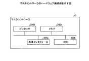
(ハードウェア)
マスタコントローラ30と各クラウド管理サーバ10は、同様のハードウェア構成を有するので、ここでは、マスタコントローラ30について説明する。図23は、マスタコントローラ30のハードウェア構成例を示す図である。図23に示すように、マスタコントローラ30は、通信インタフェース300a、HDD(Hard Disk Drive)300b、メモリ300c、CPU(Central Processing Unit)などのプロセッサ300dを有する。また、図23に示した各部は、バス等で相互に接続される。(hardware)
Since the
通信インタフェース300aは、ネットワークインタフェースカードなどである。HDD300bは、図2に示した機能を動作させるプログラムやテーブルを記憶する。 The
プロセッサ300dは、図2に示した各処理部と同様の処理を実行するプログラムをHDD300b等から読み出してメモリ300cに展開することで、図2等で説明した各機能を実行するプロセスを動作させる。すなわち、このプロセスは、マスタコントローラ300が有する各処理部と同様の機能を実行する。具体的には、プロセッサ300dは、収集部51、電力計画部52、管理部53、配備部54、移動計画部55、計画実行部56等と同様の機能を有するプログラムをHDD300b等から読み出す。そして、プロセッサ300dは、収集部51、電力計画部52、管理部53、配備部54、移動計画部55、計画実行部56等と同様の処理を実行するプロセスを実行する。 The
このようにマスタコントローラ30は、プログラムを読み出して実行することでクラウド管理方法を実行する情報処理装置として動作する。また、マスタコントローラ30は、媒体読取装置によって記録媒体から上記プログラムを読み出し、読み出された上記プログラムを実行することで上記した実施例と同様の機能を実現することもできる。なお、この他の実施例でいうプログラムは、マスタコントローラ30によって実行されることに限定されるものではない。例えば、他のコンピュータまたはサーバがプログラムを実行する場合や、これらが協働してプログラムを実行するような場合にも、本発明を同様に適用することができる。 In this way, the
(システム)
また、本実施例において説明した各処理のうち、自動的におこなわれるものとして説明した処理の全部または一部を手動的におこなうこともできる。あるいは、手動的におこなわれるものとして説明した処理の全部または一部を公知の方法で自動的におこなうこともできる。この他、上記文書中や図面中で示した処理手順、制御手順、具体的名称、各種のデータやパラメータを含む情報については、特記する場合を除いて任意に変更することができる。(system)
Further, among the processes described in this embodiment, all or a part of the processes described as being automatically performed can be manually performed. Alternatively, all or part of the processing described as being performed manually can be automatically performed by a known method. In addition, the processing procedure, control procedure, specific name, and information including various data and parameters shown in the above document and drawings can be arbitrarily changed unless otherwise specified.
また、図示した各装置の各構成要素は機能概念的なものであり、必ずしも物理的に図示の如く構成されていることを要しない。すなわち、各装置の分散や統合の具体的形態は図示のものに限られない。つまり、その全部または一部を、各種の負荷や使用状況などに応じて、任意の単位で機能的または物理的に分散・統合して構成することができる。さらに、各装置にて行なわれる各処理機能は、その全部または任意の一部が、CPUおよび当該CPUにて解析実行されるプログラムにて実現され、あるいは、ワイヤードロジックによるハードウェアとして実現され得る。 Further, each component of each of the illustrated devices is a functional concept, and does not necessarily have to be physically configured as shown in the figure. That is, the specific forms of distribution and integration of each device are not limited to those shown in the figure. That is, all or a part thereof can be functionally or physically distributed / integrated in any unit according to various loads, usage conditions, and the like. Further, each processing function performed by each device may be realized by a CPU and a program analyzed and executed by the CPU, or may be realized as hardware by wired logic.
10 クラウド管理サーバ
11 通信部
12 記憶部
13 電力契約情報DB
14 電力使用状況DB
15 レイテンシDB
16 VMリソース管理DB
17 DCリソース管理DB
20 制御部
21 電力情報収集部
22 レイテンシ測定部
23 稼働情報収集部
24 移動実行部
30 マスタコントローラ
31 通信部
32 記憶部
33 拠点情報DB
34 電力会社DB
35 電力使用実績DB
36 電力使用状況DB
37 VMリソース管理DB
38 DCリソース管理DB
39 環境負荷DB
40 電力需要予測DB
41 レイテンシDB
42 帯域管理DB
43 移動計画DB
50 制御部
51 収集部
52 電力計画部
53 管理部
54 配備部
55 移動計画部
56 計画実行部10 Cloud management server 11
14 Power usage DB
15 Latency DB
16 VM resource management DB
17 DC resource management DB
20
34 Electric power company DB
35 Power usage record DB
36 Power usage DB
37 VM resource management DB
38 DC resource management DB
39 Environmental load DB
40 Electric power demand forecast DB
41 Latency DB
42 Bandwidth management DB
43 Movement plan DB
50
Claims (9)
Translated fromJapanese前記各仮想マシンの配備後、前記各データセンタが提供する各クラウドサービスに関し、前記各クラウドサービスで仮想マシンを利用する際の電力に関する料金情報を収集する収集部と、
前記各クラウドサービスで動作する各仮想マシンに関し、前記各仮想マシンの稼働情報を取得する取得部と、
前記各クラウドサービスの料金情報と前記各仮想マシンの稼働状況とに基づいて、前記各仮想マシンの移動計画を生成する生成部と
を有することを特徴とする情報処理装置。Based on the power demand of each data center installed in different areas and the latency between the data centers, a plurality of data centers having the latency below the threshold are constrained not to exceed the contract power at the peak of the power demand. , The deployment unit that deploys each virtual machine in each data center,
After the deployment of each virtual machine, with respect to each cloud service provided by each data center, a collection unit that collects charge information regarding electricity when using the virtual machine in each cloud service, and a collection unit.
With respect to each virtual machine operating in each cloud service, an acquisition unit for acquiring operation information of each virtual machine and an acquisition unit.
An information processing device having a generation unit that generates a movement plan for each virtual machine based on the charge information of each cloud service and the operating status of each virtual machine.
前記生成部は、前記各仮想マシンの前記生存時間を比較し、前記生存時間が相対的に長い仮想マシンを電力料金が相対的に安いクラウドサービスに移動し、前記生存時間が相対的に短い仮想マシンを電力料金が相対的に高いクラウドサービスに移動する前記移動計画を生成することを特徴とする請求項1に記載の情報処理装置。The acquisition unit acquires the survival time, which is the cumulative time since each virtual machine is deployed on the cloud service, as the operation information of each virtual machine.
The generation unit compares the survival time of each of the virtual machines, moves the virtual machine having a relatively long survival time to a cloud service having a relatively low power charge, and virtual machines having a relatively short survival time. The information processing apparatus according to claim 1, wherein a movement plan for moving a machine to a cloud service having a relatively high electric power charge is generated.
前記生成部は、前記生存時間が相対的に長くかつ使用する前記資源が相対的に多い仮想マシンを前記電力料金が相対的に安いクラウドサービスに移動し、前記生存時間が相対的に短くかつ使用する前記資源が想定的に少ない仮想マシンを前記電力料金が相対的に高いクラウドサービスに移動する前記移動計画を生成することを特徴とする請求項2に記載の情報処理装置。The acquisition unit further acquires resource information regarding the resources used by each of the virtual machines.
The generation unit moves the virtual machine having a relatively long survival time and using a relatively large amount of resources to a cloud service having a relatively low power charge, and has a relatively short survival time and uses the virtual machine. The information processing apparatus according to claim 2, wherein a movement plan for moving a virtual machine having a relatively small amount of resources to a cloud service having a relatively high power charge is generated.
前記電力料金が相対的に安いクラウドサービスに移動した複数の前記仮想マシンのうち、前記稼働率が所定値未満の仮想マシンを、前記電力料金が相対的に高いクラウドサービスに移動する再移動部と、をさらに有することを特徴とする請求項2に記載の情報処理装置。A calculation unit that calculates the operating rate of each virtual machine after a predetermined time has elapsed after the movement plan is executed.
Among the plurality of virtual machines that have moved to the cloud service having a relatively low power charge, the virtual machine having an operating rate of less than a predetermined value is moved to the cloud service having a relatively high power charge. The information processing apparatus according to claim 2, further comprising.
異なる地域に設置された各データセンタの電力需要と前記各データセンタ間のレイテンシに基づき、前記レイテンシが閾値以下である複数のデータセンタが前記電力需要のピーク時に契約電力を越えない制約のもと、各仮想マシンを前記各データセンタに配備し、
前記各仮想マシンの配備後、前記各データセンタが提供する各クラウドサービスに関し、前記各クラウドサービスで仮想マシンを利用する際の電力に関する料金情報を収集し、
前記各クラウドサービスで動作する各仮想マシンに関し、前記各仮想マシンの稼働情報を取得し、
前記各クラウドサービスの料金情報と前記各仮想マシンの稼働状況とに基づいて、前記各仮想マシンの移動計画を生成する
処理を実行することを特徴とする情報処理方法。The computer
Based on the power demand of each data center installed in different areas and the latency between the data centers, a plurality of data centers having the latency below the threshold are constrained not to exceed the contract power at the peak of the power demand. , Deploy each virtual machine in each of the above data centers,
After deploying each virtual machine, for each cloud service provided by each data center, charge information regarding electric power when using the virtual machine in each cloud service is collected.
For each virtual machine operating in each cloud service, the operation information of each virtual machine is acquired, and the operation information is acquired.
An information processing method characterized by executing a process of generating a movement plan of each virtual machine based on the charge information of each cloud service and the operating status of each virtual machine.
異なる地域に設置された各データセンタの電力需要と前記各データセンタ間のレイテンシに基づき、前記レイテンシが閾値以下である複数のデータセンタが前記電力需要のピーク時に契約電力を越えない制約のもと、各仮想マシンを前記各データセンタに配備し、
前記各仮想マシンの配備後、前記各データセンタが提供する各クラウドサービスに関し、前記各クラウドサービスで仮想マシンを利用する際の電力に関する料金情報を収集し、
前記各クラウドサービスで動作する各仮想マシンに関し、前記各仮想マシンの稼働情報を取得し、
前記各クラウドサービスの料金情報と前記各仮想マシンの稼働状況とに基づいて、前記各仮想マシンの移動計画を生成する
処理を実行させることを特徴とする情報処理プログラム。On the computer
Based on the power demand of each data center installed in different areas and the latency between the data centers, a plurality of data centers having the latency below the threshold are constrained not to exceed the contract power at the peak of the power demand. , Deploy each virtual machine in each of the above data centers,
After deploying each virtual machine, for each cloud service provided by each data center, charge information regarding electric power when using the virtual machine in each cloud service is collected.
For each virtual machine operating in each cloud service, the operation information of each virtual machine is acquired, and the operation information is acquired.
An information processing program characterized by executing a process of generating a movement plan of each virtual machine based on the charge information of each cloud service and the operating status of each virtual machine.
前記複数の管理サーバそれぞれは、
異なる地域に設置された各データセンタの電力需要と前記各データセンタ間のレイテンシに基づき、前記レイテンシが閾値以下である複数のデータセンタが前記電力需要のピーク時に契約電力を越えない制約のもと、各仮想マシンが配備された前記各データセンタのうち、管理対象の地域に設置されたデータセンタが提供するクラウドサービスに関し、前記クラウドサービスで仮想マシンを利用する際の電力に関する料金情報を前記統合サーバに送信する第1送信部と、
前記クラウドサービスで動作する各仮想マシンに関し、前記各仮想マシンの稼働情報を前記統合サーバに送信する第2送信部と、を有し、
前記統合サーバは、
前記複数の管理サーバそれぞれから、各クラウドサービスに関する前記料金情報と各仮想マシンに関する前記稼働情報を受信する受信部と、
前記各クラウドサービスの料金情報と前記各仮想マシンの稼働状況とに基づいて、前記各仮想マシンの移動計画を生成する生成部と
を有することを特徴とする情報処理システム。In an information processing system that has multiple management servers and an integrated server
Each of the plurality of management servers
Based on the power demand of each data center installed in different regions and the latency between the data centers, a plurality of data centers having the latency below the threshold are constrained not to exceed the contract power at the peak of the power demand. , Of the data centers where each virtual machine is deployed, regarding the cloud service provided by the data center installed inthe managed area, the charge information regarding the power when using the virtual machine in the cloud service is integrated. The first transmitter that sends to the server
With respect to each virtual machine operating in the cloud service, it has a second transmission unit that transmits operation information of each virtual machine to the integrated server.
The integrated server
A receiver that receives the charge information for each cloud service and the operation information for each virtual machine from each of the plurality of management servers.
An information processing system having a generation unit that generates a movement plan for each virtual machine based on the charge information of each cloud service and the operating status of each virtual machine.
Priority Applications (2)
| Application Number | Priority Date | Filing Date | Title |
|---|---|---|---|
| JP2016160895AJP6819131B2 (en) | 2016-08-18 | 2016-08-18 | Information processing equipment, information processing methods, information processing programs and information processing systems |
| US15/666,717US10877789B2 (en) | 2016-08-18 | 2017-08-02 | Migrating VMs based on electricity costs of a plurality of data centers and resource load index, and lifetime of a plurality of VMs |
Applications Claiming Priority (1)
| Application Number | Priority Date | Filing Date | Title |
|---|---|---|---|
| JP2016160895AJP6819131B2 (en) | 2016-08-18 | 2016-08-18 | Information processing equipment, information processing methods, information processing programs and information processing systems |
Publications (2)
| Publication Number | Publication Date |
|---|---|
| JP2018028824A JP2018028824A (en) | 2018-02-22 |
| JP6819131B2true JP6819131B2 (en) | 2021-01-27 |
Family
ID=61191753
Family Applications (1)
| Application Number | Title | Priority Date | Filing Date |
|---|---|---|---|
| JP2016160895AExpired - Fee RelatedJP6819131B2 (en) | 2016-08-18 | 2016-08-18 | Information processing equipment, information processing methods, information processing programs and information processing systems |
Country Status (2)
| Country | Link |
|---|---|
| US (1) | US10877789B2 (en) |
| JP (1) | JP6819131B2 (en) |
Families Citing this family (14)
| Publication number | Priority date | Publication date | Assignee | Title |
|---|---|---|---|---|
| US10423455B2 (en)* | 2017-02-03 | 2019-09-24 | Microsoft Technology Licensing, Llc | Method for deploying virtual machines in cloud computing systems based on predicted lifetime |
| CN109842636A (en) | 2017-11-24 | 2019-06-04 | 阿里巴巴集团控股有限公司 | Cloud service moving method, device and electronic equipment |
| US10963353B2 (en)* | 2018-10-23 | 2021-03-30 | Capital One Services, Llc | Systems and methods for cross-regional back up of distributed databases on a cloud service |
| US11210124B2 (en)* | 2019-01-11 | 2021-12-28 | Hewlett Packard Enterprise Development Lp | Movement of virtual machine data across clusters of nodes |
| JP7287068B2 (en)* | 2019-04-01 | 2023-06-06 | 富士通株式会社 | Information processing program, information processing method, and information processing apparatus |
| JP7415351B2 (en)* | 2019-07-09 | 2024-01-17 | 富士フイルムビジネスイノベーション株式会社 | Control device and control program |
| CN110362383B (en)* | 2019-07-12 | 2022-06-24 | 东北大学 | P-E balanced VM migration method for seasonal non-stationary concurrency |
| US11392400B2 (en)* | 2019-07-17 | 2022-07-19 | Hewlett Packard Enterprise Development Lp | Enhanced migration of clusters based on data accessibility |
| JP7482688B2 (en)* | 2020-06-01 | 2024-05-14 | 株式会社日立製作所 | Data center system and its operation method, and data center system site design support device and method |
| JP2022017686A (en) | 2020-07-14 | 2022-01-26 | 富士通株式会社 | Container arrangement destination cluster determination method, container arrangement destination cluster determination device and container arrangement destination cluster determination system |
| US12067417B2 (en)* | 2021-04-16 | 2024-08-20 | International Business Machines Corporation | Automatic container migration system |
| US11675518B2 (en)* | 2021-05-04 | 2023-06-13 | EMC IP Holding Company LLC | Determining migrations between geographically distributed data centers |
| WO2023152896A1 (en)* | 2022-02-10 | 2023-08-17 | 日本電信電話株式会社 | Virtual machine power consumption predicting device, virtual machine power consumption predicting method, and program |
| CN115640119B (en)* | 2022-09-07 | 2025-09-26 | 福建天泉教育科技有限公司 | Task scheduling method and terminal |
Family Cites Families (18)
| Publication number | Priority date | Publication date | Assignee | Title |
|---|---|---|---|---|
| US6393458B1 (en)* | 1999-01-28 | 2002-05-21 | Genrad, Inc. | Method and apparatus for load balancing in a distributed object architecture |
| US9218213B2 (en)* | 2006-10-31 | 2015-12-22 | International Business Machines Corporation | Dynamic placement of heterogeneous workloads |
| JP2009134367A (en)* | 2007-11-28 | 2009-06-18 | Hitachi Ltd | Storage control device and control method of storage control device |
| JP4488072B2 (en) | 2008-01-18 | 2010-06-23 | 日本電気株式会社 | Server system and power reduction method for server system |
| KR20110007205A (en)* | 2008-04-21 | 2011-01-21 | 어댑티브 컴퓨팅 엔터프라이즈 인코포레이티드 | Systems and Methods for Managing Energy Consumption in Compute Environments |
| US9501124B2 (en)* | 2008-05-22 | 2016-11-22 | Microsoft Technology Licensing, Llc | Virtual machine placement based on power calculations |
| JP2011018167A (en)* | 2009-07-08 | 2011-01-27 | Fujitsu Ltd | Load balancing program, load balancing device, and load balancing method |
| US8930731B2 (en)* | 2009-07-21 | 2015-01-06 | Oracle International Corporation | Reducing power consumption in data centers having nodes for hosting virtual machines |
| JP4824807B2 (en)* | 2009-09-30 | 2011-11-30 | 株式会社野村総合研究所 | Load management apparatus, information processing system, and load management method |
| US9207993B2 (en)* | 2010-05-13 | 2015-12-08 | Microsoft Technology Licensing, Llc | Dynamic application placement based on cost and availability of energy in datacenters |
| JP5601024B2 (en) | 2010-05-20 | 2014-10-08 | 富士通株式会社 | Power leveling method, system and program |
| KR101544482B1 (en)* | 2011-03-15 | 2015-08-21 | 주식회사 케이티 | Cloud center controlling apparatus and cloud center selecting method of the same |
| CN103827823A (en)* | 2011-07-29 | 2014-05-28 | 惠普发展公司,有限责任合伙企业 | Migrating virtual machines |
| JP5785050B2 (en) | 2011-10-27 | 2015-09-24 | 株式会社日立製作所 | Information processing system, power saving control method thereof, and apparatus |
| US9274581B2 (en)* | 2013-06-24 | 2016-03-01 | Dell Products, Lp | Date adjusted power budgeting for an information handling system |
| US9832081B2 (en)* | 2014-09-29 | 2017-11-28 | International Business Machines Corporation | Allocating physical nodes for processes in an execution plan |
| US9678783B2 (en)* | 2015-10-14 | 2017-06-13 | International Business Machines Corporation | Temporal dynamic virtual machine policies |
| TWI595760B (en)* | 2015-12-01 | 2017-08-11 | 廣達電腦股份有限公司 | Server resource management system and management method thereof |
- 2016
- 2016-08-18JPJP2016160895Apatent/JP6819131B2/ennot_activeExpired - Fee Related
- 2017
- 2017-08-02USUS15/666,717patent/US10877789B2/ennot_activeExpired - Fee Related
Also Published As
| Publication number | Publication date |
|---|---|
| US10877789B2 (en) | 2020-12-29 |
| JP2018028824A (en) | 2018-02-22 |
| US20180052704A1 (en) | 2018-02-22 |
Similar Documents
| Publication | Publication Date | Title |
|---|---|---|
| JP6819131B2 (en) | Information processing equipment, information processing methods, information processing programs and information processing systems | |
| KR102238094B1 (en) | Systems and methods for managing exchangeable energy storage device stations | |
| KR102286936B1 (en) | Systems and methods for predicting demands for exchangeable energy storage devices | |
| CN103401938B (en) | Resource allocation system and method based on business characteristics under distributed cloud architecture | |
| US8793365B2 (en) | Environmental and computing cost reduction with improved reliability in workload assignment to distributed computing nodes | |
| CN100472519C (en) | Dynamic query optimization method, device and computer program | |
| CN104391737B (en) | The optimization method of load balance in cloud platform | |
| CN108090225B (en) | Database instance running method, device and system and computer readable storage medium | |
| JP6881575B2 (en) | Resource allocation systems, management equipment, methods and programs | |
| JP5664098B2 (en) | Composite event distribution apparatus, composite event distribution method, and composite event distribution program | |
| US10379834B2 (en) | Tenant allocation in multi-tenant software applications | |
| CN112988390A (en) | Calculation power resource allocation method and device | |
| EP2391961A1 (en) | System and method for integrating capacity planning and workload management | |
| CN103377091A (en) | Method and system for efficient execution of jobs in a shared pool of resources | |
| CN104407926A (en) | Scheduling method of cloud computing resources | |
| WO2014136302A1 (en) | Task management device and task management method | |
| EP4206915A1 (en) | Container creation method and apparatus, electronic device, and storage medium | |
| CN112463395A (en) | Resource allocation method, device, equipment and readable storage medium | |
| KR102860324B1 (en) | Resource scheduling method and system, electronic device, and computer-readable storage medium | |
| CN108459905A (en) | Resource pool method for planning capacity and server | |
| CN104035542A (en) | Virtual machine migration method and system for balancing calculation energy consumption and refrigeration energy consumption | |
| JP2005250823A (en) | Multiple computer operation system | |
| Dieye et al. | On achieving high data availability in heterogeneous cloud storage systems | |
| CN119537027B (en) | Resource allocation method, device, equipment and storage medium based on intelligent computing cluster | |
| US11823294B1 (en) | Site management apparatus and management method |
Legal Events
| Date | Code | Title | Description |
|---|---|---|---|
| A621 | Written request for application examination | Free format text:JAPANESE INTERMEDIATE CODE: A621 Effective date:20190513 | |
| A977 | Report on retrieval | Free format text:JAPANESE INTERMEDIATE CODE: A971007 Effective date:20200309 | |
| A131 | Notification of reasons for refusal | Free format text:JAPANESE INTERMEDIATE CODE: A131 Effective date:20200407 | |
| A521 | Request for written amendment filed | Free format text:JAPANESE INTERMEDIATE CODE: A523 Effective date:20200604 | |
| TRDD | Decision of grant or rejection written | ||
| A01 | Written decision to grant a patent or to grant a registration (utility model) | Free format text:JAPANESE INTERMEDIATE CODE: A01 Effective date:20201201 | |
| A61 | First payment of annual fees (during grant procedure) | Free format text:JAPANESE INTERMEDIATE CODE: A61 Effective date:20201214 | |
| R150 | Certificate of patent or registration of utility model | Ref document number:6819131 Country of ref document:JP Free format text:JAPANESE INTERMEDIATE CODE: R150 | |
| LAPS | Cancellation because of no payment of annual fees |