JP6817565B2 - Power converter, power conversion system - Google Patents
Power converter, power conversion systemDownload PDFInfo
- Publication number
- JP6817565B2 JP6817565B2JP2017068992AJP2017068992AJP6817565B2JP 6817565 B2JP6817565 B2JP 6817565B2JP 2017068992 AJP2017068992 AJP 2017068992AJP 2017068992 AJP2017068992 AJP 2017068992AJP 6817565 B2JP6817565 B2JP 6817565B2
- Authority
- JP
- Japan
- Prior art keywords
- power
- inverter
- amount
- control circuit
- change
- Prior art date
- Legal status (The legal status is an assumption and is not a legal conclusion. Google has not performed a legal analysis and makes no representation as to the accuracy of the status listed.)
- Active
Links
Images


Landscapes
- Control Of Electrical Variables (AREA)
- Dc-Dc Converters (AREA)
- Inverter Devices (AREA)
Description
Translated fromJapanese本発明は、直流電力を交流電力に変換する電力変換装置、電力変換システムに関する。 The present invention relates to a power conversion device and a power conversion system that convert DC power into AC power.
現在、系統連系される分散型電源には、電源ソースとして太陽光発電装置、風力発電装置、定置型蓄電池、車載蓄電池などがある。再生可能エネルギーを使用した発電装置である太陽光発電装置または風力発電装置により発電された電力は、宅内の負荷電力を上回った場合でも、電力系統へ逆潮流することが認められている。一方、蓄電・蓄エネルギー装置である定置型蓄電池または車載蓄電池からは、規定時間(日本では500ms)を超えて電力系統へ逆潮流することが認められておらず、宅内の負荷電力に追従する制御が行われている。即ち、定置型蓄電池または車載蓄電池からの放電量は、負荷の消費電力以下に抑える必要がある。 Currently, distributed power sources connected to the grid include solar power generation devices, wind power generation devices, stationary storage batteries, in-vehicle storage batteries, and the like as power sources. Electricity generated by a photovoltaic power generation device or a wind power generation device, which is a power generation device using renewable energy, is allowed to reverse power flow to the power system even if it exceeds the load power in the house. On the other hand, the stationary storage battery or the in-vehicle storage battery, which is a storage / energy storage device, is not allowed to reverse power flow to the power system beyond the specified time (500 ms in Japan), and the control follows the load power in the house. Is being done. That is, the amount of discharge from the stationary storage battery or the in-vehicle storage battery needs to be suppressed to be equal to or less than the power consumption of the load.
系統に連系する分散型電源システムの代表的な構成として、単一の分散型電源を使用してDC−DCコンバータ、直流バス及びインバータを介して系統連系する構成と、複数の分散型電源を使用してそれぞれのDC−DCコンバータ、共通の直流バス及び1つのインバータを介して系統連系する構成がある(例えば、特許文献1参照)。 Typical configurations of a distributed power supply system connected to a grid include a configuration in which a single distributed power supply is used and the grid is connected via a DC-DC converter, a DC bus, and an inverter, and a plurality of distributed power supplies. There is a configuration in which each DC-DC converter, a common DC bus, and one inverter are connected to the grid using the above (see, for example, Patent Document 1).
後者において、複数のDC−DCコンバータと1つのインバータが1つの筐体内に設置される構成と、少なくとも1つのDC−DCコンバータと1つのインバータが分離された筐体内に設置される構成がある。 In the latter, there is a configuration in which a plurality of DC-DC converters and one inverter are installed in one housing, and a configuration in which at least one DC-DC converter and one inverter are installed in a separate housing.
また、物理的に1つの筐体内にDC−DCコンバータとインバータが設置される構成であっても、制御的にはDC−DCコンバータとインバータが別々の制御装置(例えば、マイコン)により独立に制御されることもある。このようなDC−DCコンバータとインバータが物理的もしくは制御的に分離された分散型電源システムでは、それぞれの電力変換部間の調整を行う必要がある。 Further, even if the DC-DC converter and the inverter are physically installed in one housing, the DC-DC converter and the inverter are controlled independently by separate control devices (for example, a microcomputer) in terms of control. It may be done. In such a distributed power supply system in which the DC-DC converter and the inverter are physically or controlledly separated, it is necessary to perform coordination between the respective power conversion units.
上述の分散型電源システムにおいて、負荷の急変時において、負荷変動にインバータ及び/又はDC−DCコンバータの応答が追従できず、規定時間を超える逆潮流を発生させてしまうことがあった。 In the above-mentioned distributed power supply system, when the load suddenly changes, the response of the inverter and / or the DC-DC converter cannot follow the load fluctuation, and a reverse power flow exceeding a specified time may be generated.
本発明はこうした状況に鑑みなされたものであり、その目的は、負荷の急変時において、追従遅れが小さい電力変換装置、電力変換システムを提供することにある。 The present invention has been made in view of such a situation, and an object of the present invention is to provide a power conversion device and a power conversion system having a small follow-up delay when a load suddenly changes.
上記課題を解決するために、本発明のある態様の電力変換装置は、直流電力を交流電力に変換し、当該交流電力を電力系統へ重畳し、重畳した交流電力を負荷へ供給するインバータと、前記インバータを制御する制御回路と、を備える。前記制御回路は、前記電力系統への逆潮流電力の単位周期当たりの変化量に応じて、前記インバータの指令値の変更量を決定する。 In order to solve the above problems, the power conversion device of a certain aspect of the present invention includes an inverter that converts DC power into AC power, superimposes the AC power on the power system, and supplies the superposed AC power to the load. It includes a control circuit for controlling the inverter. The control circuit determines the amount of change in the command value of the inverter according to the amount of change in the reverse power flow power to the power system per unit cycle.
本発明によれば、負荷の急変時において、インバータ出力の追従遅れを小さくすることができる。 According to the present invention, it is possible to reduce the follow-up delay of the inverter output when the load suddenly changes.
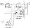
図1は、本発明の実施の形態に係る電力変換システム1を説明するための図である。電力変換システム1は、第1電力変換装置10及び第2電力変換装置20を備える。第1電力変換装置10は太陽電池2用のパワーコンディショナシステムであり、第2電力変換装置20は蓄電部3用のパワーコンディショナシステムである。図1では、太陽電池2用のパワーコンディショナシステムに、蓄電部3用のパワーコンディショナシステムを後付けした例を示している。 FIG. 1 is a diagram for explaining a
太陽電池2は、光起電力効果を利用し、光エネルギーを直接電力に変換する発電装置である。太陽電池2として、シリコン太陽電池、化合物半導体などを素材にした太陽電池、色素増感型(有機太陽電池)等が使用される。太陽電池2は第1電力変換装置10と接続され、発電した電力を第1電力変換装置10に出力する。 The solar cell 2 is a power generation device that directly converts light energy into electric power by utilizing the photovoltaic effect. As the solar cell 2, a silicon solar cell, a solar cell made of a compound semiconductor or the like, a dye-sensitized type (organic solar cell), or the like is used. The solar cell 2 is connected to the first
第1電力変換装置10は、DC−DCコンバータ11、コンバータ制御回路12、インバータ13、インバータ制御回路14、及びシステム制御回路15を備える。システム制御回路15は、逆潮流電力計測部15a、指令値生成部15b、及び通信制御部15cを含む。DC−DCコンバータ11とインバータ13間は直流バス40で接続される。コンバータ制御回路12とシステム制御回路15間は通信線41で接続され、両者の間で所定のシリアル通信規格(例えば、例えばRS−485規格、TCP−IP規格)に準拠した通信が行われる。 The first
DC−DCコンバータ11は、太陽電池2から出力される直流電力を、所望の電圧値の直流電力に変換し、変換した直流電力を直流バス40に出力する。DC−DCコンバータ11は例えば、昇圧チョッパで構成することができる。 The DC-
コンバータ制御回路12はDC−DCコンバータ11を制御する。コンバータ制御回路12は基本制御として、太陽電池2の出力電力が最大になるようDC−DCコンバータ11をMPPT(Maximum Power Point Tracking) 制御する。具体的にはコンバータ制御回路12は、太陽電池2の出力電圧および出力電流である、DC−DCコンバータ11の入力電圧および入力電流を計測して太陽電池2の発電電力を推定する。コンバータ制御回路12は、計測した太陽電池2の出力電圧と推定した発電電力をもとに、太陽電池2の発電電力を最大電力点(最適動作点)にするための指令値を生成する。例えば、山登り法に従い動作点電圧を所定のステップ幅で変化させて最大電力点を探索し、最大電力点を維持するように指令値を生成する。DC−DCコンバータ11は、生成された指令値に基づく駆動信号に応じてスイッチング動作する。 The
インバータ13は双方向インバータであり、直流バス40から入力される直流電力を交流電力に変換し、変換した交流電力を商用電力系統(以下、単に系統4という)に接続された配電線50に出力する。またインバータ13は、系統4から供給される交流電力を直流電力に変換し、変換した直流電力を直流バス40に出力する。直流バス40には、平滑用の電解コンデンサ(不図示)が接続されている。上記配電線50には負荷5が接続される。電力変換システム1が家庭用の場合、負荷5は家庭内の負荷の総称である。電力変換システム1が業務用の場合、負荷5は業務用の負荷の総称である。以下の説明では家庭用を想定する。 The
インバータ制御回路14はインバータ13を制御する。インバータ制御回路14は基本制御として、直流バス40の電圧が第1閾値電圧を維持するようにインバータ13を制御する。具体的にはインバータ制御回路14は、直流バス40の電圧を検出し、検出したバス電圧を第1閾値電圧に一致させるための指令値を生成する。インバータ制御回路14は、直流バス40の電圧が第1閾値電圧より高い場合はインバータ13のデューティ比を上げるための指令値を生成し、直流バス40の電圧が第1閾値電圧より低い場合はインバータ13のデューティ比を下げるための指令値を生成する。インバータ13は、生成された指令値に基づく駆動信号に応じてスイッチング動作する。 The
蓄電部3は、電力を充放電可能であり、リチウムイオン蓄電池、ニッケル水素蓄電池、鉛蓄電池、電気二重層キャパシタ、リチウムイオンキャパシタ等を含む。蓄電部3は第2電力変換装置20と接続される。 The
第2電力変換装置20は、DC−DCコンバータ21及びコンバータ制御回路22を備える。コンバータ制御回路22と、第1電力変換装置10のシステム制御回路15は通信線42で接続され、両者の間で所定のシリアル通信規格に準拠した通信が行われる。 The
DC−DCコンバータ21は、蓄電部3と直流バス40の間に接続され、蓄電部3を充放電する双方向コンバータである。コンバータ制御回路22はDC−DCコンバータ21を制御する。コンバータ制御回路22は基本制御として、システム制御回路15から送信されてくる指令値をもとにDC−DCコンバータ21を制御して、蓄電部3を定電流(CC)/定電圧(CV)で充電/放電する。例えばコンバータ制御回路22は、放電時においてシステム制御回路15から電力指令値を受信し、当該電力指令値を蓄電部3の電圧で割った値を電流指令値として、DC−DCコンバータ21に定電流放電させる。 The DC-
蓄電部3からの放電中に、日射変動により太陽電池2の発電量が増加した場合、又は負荷5の消費電力が低下した場合、系統4への逆潮流電力が発生し、売電状態になることがある。日本では系統連系規程により蓄電システムから、蓄電池の定格容量の5%以上の電力を500msを超えて系統4へ逆潮流することが禁止されている。従って、蓄電部3が接続された電力変換システム1において逆潮流が検出された場合、500ms以内に逆潮流を抑える必要がある。 If the amount of power generated by the solar cell 2 increases due to fluctuations in solar radiation or the power consumption of the load 5 decreases during discharge from the
インバータ13の出力電力を抑制する方法として、太陽電池2のDC−DCコンバータ11の出力電力を抑制する方法、蓄電部3のDC−DCコンバータ21の出力電力を抑制する方法、インバータ13の出力電力を抑制する方法がある。太陽電池2のDC−DCコンバータ11の出力電力を抑制する方法は、太陽電池2の発電量を無駄にすることに繋がる。従って太陽電池2のDC−DCコンバータ11の出力抑制は最後に実行すべき制御である。 As a method of suppressing the output power of the
逆潮流が検出された場合、蓄電部3からの放電を停止すればよいため、蓄電部3のDC−DCコンバータ21の出力電力を抑制する方法が最も直截的な制御である。しかしながら、第2電力変換装置20が第1電力変換装置10から分離され、系統4から離れた位置に設置されている場合、逆潮流の検出から蓄電部3のDC−DCコンバータ21の出力抑制までにタイムラグが発生しやすくなる。 When reverse power flow is detected, the discharge from the
図1に示した構成では、第1電力変換装置10の逆潮流電力計測部15aが、配電線50の、分電盤より系統4側に設置されたCTセンサ(不図示)の計測値をもとに逆潮流電力を検出する。第2電力変換装置20のコンバータ制御回路22は、システム制御回路15から通信線42を介して逆潮流の検出情報を受信する。通信線42は、第1電力変換装置10と第2電力変換装置20を繋ぐ直流バス40に這わせて設置されることが多く、この構成では通信線42は直流バス40からノイズの影響を受ける。また二値の電圧を使用したデジタル通信では、1ビットを表す単位期間を短くするほどノイズに弱くなる性質があり、基本的に通信速度を上げるほどビット誤りが発生しやすくなる。 In the configuration shown in FIG. 1, the reverse power flow
従って第1電力変換装置10が逆潮流を検出し、出力抑制を指示する通信データを生成し、通信線42を介して第2電力変換装置20に送信する方法では、系統連系規程に定められる時限(500ms)を遵守できない可能性がある。またノイズにより通信データの内容が途中で変わってしまう可能性もある。 Therefore, a method in which the first
そこで先にインバータ13の出力電力を抑制し、後から蓄電部3のDC−DCコンバータ21の出力電力を抑制する方法が考えられる。上述のようにインバータ制御回路14は基本制御として、直流バス40の電圧が第1閾値電圧を維持するようにインバータ13を制御する。出力抑制をすべき場合は、インバータ制御回路14は優先制御として、出力抑制制御を実行する。具体的にはインバータ制御回路14は、インバータ13の出力が指令値生成部15bにより生成された指令値(具体的には上限電流値または上限電力値)を超えないようにインバータ13を制御する。出力抑制中は、直流バス40の電圧を第1閾値電圧に維持するように制御するバス電圧の安定化制御は停止する。 Therefore, a method of first suppressing the output power of the
インバータ13の出力抑制が開始した時点では、太陽電池2のDC−DCコンバータ11及び/又は蓄電部3のDC−DCコンバータ21の出力抑制は開始していない。従ってインバータ13の出力電力に対してインバータ13の入力電力が過多となり、直流バス40の電圧が上昇する。より具体的には直流バス40に接続された電解コンデンサに電荷が蓄積されていく。 When the output suppression of the
上述のようにコンバータ制御回路22は基本制御として、蓄電部3からDC−DCコンバータ21への放電量またはDC−DCコンバータ21から蓄電部3への充電量が、システム制御回路15から送信されてくる指令値になるようにDC−DCコンバータ21を制御する。さらにコンバータ制御回路22は優先制御として、直流バス40の電圧が第2閾値電圧を超えないようにDC−DCコンバータ21を制御する。この制御は、システム制御回路15から送信されてくる指令値に出力を合わせる制御に対して優先する。第2閾値電圧は第1閾値電圧より高い値に設定される。 As described above, as basic control of the
上述のようにコンバータ制御回路12は基本制御として、太陽電池2の出力電力が最大になるようDC−DCコンバータ11をMPPT制御する。さらにコンバータ制御回路12は優先制御として、直流バス40の電圧が第3閾値電圧を超えないようにDC−DCコンバータ11を制御する。この制御は、MPPT制御に対して優先する。第3閾値電圧は第2閾値電圧より高い値に設定される。 As described above, the
第1閾値電圧は、直流バス40の定常時の電圧に設定される。系統電圧がAC200Vの場合、第1閾値電圧は例えば、DC280V〜360Vの範囲に設定される。第2閾値電圧は例えば390V、第3閾値電圧は例えば410Vに設定される。インバータ13の出力抑制により直流バス40の電圧が上昇し、直流バス40の電圧が第2閾値電圧に到達すると蓄電部3のDC−DCコンバータ21によるバス電圧の上昇抑制制御が発動する。直流バス40の電圧上昇のエネルギーが、蓄電部3のDC−DCコンバータ21による上昇抑制エネルギーより大きい場合は、直流バス40の電圧がさらに上昇する。直流バス40の電圧が第3閾値電圧に到達すると太陽電池2のDC−DCコンバータ11によるバス電圧の上昇抑制制御が発動する。 The first threshold voltage is set to the steady state voltage of the
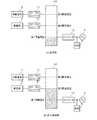
図2(a)、(b)は、直流バス40の電圧の状態を模式的に描いた図である。図2(a)は、定常時の直流バス40の電圧の状態を示している。定常時の直流バス40の電圧は、インバータ13により第1閾値電圧に維持される。図2(b)は、インバータ13の出力抑制時の直流バス40の電圧の状態を示している。通常、出力抑制中の直流バス40の電圧は、蓄電部3のDC−DCコンバータ21により第2閾値電圧に維持される。 2 (a) and 2 (b) are diagrams schematically depicting the voltage state of the
上述のようにシステム制御回路154は、蓄電部3が放電しているときは、系統4への逆潮流電流を発生させないように、インバータ13の出力電流I1及び逆潮流電流I2を監視しながら、インバータ13の出力電流I1の指令値を調整している。逆潮流電流I2は、インバータ13の出力電流I1から負荷5の消費電流を引いた値になる。 As described above, the system control circuit 154 monitors the output current I1 and the reverse power flow current I2 of the
例えば、以下の状態でインバータ13の電力平衡が保たれている事例を考える。系統電圧:AC200V、インバータ13の出力電力:1000W(インバータ13の出力電流:5A)、負荷5の消費電力:1000W(負荷5の消費電流:5A)、逆潮流電力:0W(逆潮流電流:0A)。 For example, consider a case where the power balance of the
この状態から負荷5の消費電力が500Wに急低下した場合、インバータ13の出力電力:1000W(インバータの出力電流:5A)、負荷5の消費電力:500W(負荷5の消費電流:2.5A)、逆潮流電力:500W(逆潮流電流:2.5A)となる。負荷5の急低下は例えば、消費電力が大きい電気製品(例えば、電子レンジ)がスイッチオフされた場合に発生する。 When the power consumption of the load 5 suddenly drops to 500 W from this state, the output power of the
この逆潮流電力を短時間(500ms未満)で、次の状態に収束させる必要がある。インバータ13の出力電力:500W(インバータ13の出力電流:2.5A)、負荷5の消費電力:500W(負荷5の消費電流:2.5A)、逆潮流電力:0W(逆潮流電流:0A)。 It is necessary to converge this reverse power flow to the next state in a short time (less than 500 ms). Output power of inverter 13: 500W (output current of inverter 13: 2.5A), power consumption of load 5: 500W (current consumption of load 5: 2.5A), reverse power flow power: 0W (reverse power flow current: 0A) ..
本実施の形態では負荷5の急低下時において、逆潮流電力計測部15aが逆潮流電流/逆潮流電力を検出し、指令値生成部15bがインバータ13の出力電流/出力電力を抑制するための指令値を生成し、インバータ制御回路14に設定する。インバータ制御回路14は当該指令値をもとにインバータ13の出力電流/出力電力を抑制する。それにより発生する直流バス40の電圧上昇に応じて、蓄電部3のDC−DCコンバータ21及び/又は太陽電池2のDC−DCコンバータ11は、蓄電部3及び/又は太陽電池2の出力電流/出力電力を抑制する。 In the present embodiment, when the load 5 suddenly drops, the reverse power
図3(a)、(b)は、負荷急低下時における、インバータ13の出力の推移と、インバータ13の理想特性の一例を示す図である。図3(a)において各点は、指令値により指示されるインバータ13の出力の電流点/電力点を示している。図3(b)の太線の電力推移Piは、インバータ13の出力電力の理想特性を示しており、細線の電力推移Prは、図3(a)の指令値により調整されたインバータ13の実際の出力電力の推移を示している。 3A and 3B are diagrams showing a transition of the output of the
負荷5の消費電力は瞬時に変動するが、インバータ13の出力は時定数を持っており、負荷5の消費電力の変動に対して遅延する。その遅延には、サンプリングの遅延、システム制御回路15及びインバータ制御回路14の制御の遅延も含まれる。図3(b)に示すようにインバータ13の実際の出力電力Prの抑制開始は、インバータ13の理想特性Piの出力電力の抑制開始に対して遅延する(D参照)。 The power consumption of the load 5 fluctuates instantaneously, but the output of the
上述のように蓄電部3からの放電時に系統4への逆潮流が発生すると、500ms以内にインバータ13の出力電力を抑制する必要がある。系統4の周波数が50Hzの場合、システム制御回路15のサンプリング周期は20msになり、25(500÷20)回のサンプリング周期内にインバータ13の出力電力を抑制する必要がある。なお、25回のサンプリング周期内で蓄電部3のDC−DCコンバータ21の出力電力及び/又は太陽電池2のDC−DCコンバータ11も抑制するため、インバータ13の出力抑制は、100〜200ms程度で終える必要がある。即ち、5〜10のサンプリング周期内にインバータ13の出力電力を目標値まで収束させる必要がある。 If a reverse power flow to the
システム制御回路15は、蓄電部3からの放電時に逆潮流が検出されると基本制御として、逆潮流電流/逆潮流電力の目標値がゼロになるように、インバータ13の電流指令値/電力指令値を生成する。なお逆潮流電流/逆潮流電力の目標値が負の値(例えば、−50W)になるようにインバータ13の電流指令値/電力指令値を生成してもよい。 When a reverse power flow is detected during discharge from the
システム制御回路15のサンプリング周期より負荷5の変動速度の方が速い場合、負荷5の変動に対して、インバータ13の出力抑制が遅れてしまう。例えば、負荷5の消費電力が1000Wから500Wに急低下しても、インバータ13の応答が追いつかず、インバータ13の出力電力を瞬時に500Wまで低下させることは困難である。 When the fluctuation speed of the load 5 is faster than the sampling cycle of the
そこで本実施の形態ではシステム制御回路15は、逆潮流電力の単位周期当たりの変化量ΔWに対して、予測的にマージンを持たせて、インバータ13の電流指令値から減ずべき電流値(変更量)を算出する。系統4の周波数が50Hzの場合の単位周期は20msであり、系統4の周波数が60Hzの場合の単位周期は約16.7msである。 Therefore, in the present embodiment, the
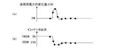
図4(a)、(b)は、逆潮流電力の単位周期当たりの変化量ΔWと、インバータ13の出力の一例を示す図である。図5は、逆潮流電力の単位周期当たりの変化量ΔWと、電流指令値の変更量の対応関係の一例を示す図である。図5は、定格出力電力が5.5kW、定格出力電流が27.5Aのインバータ13を想定している。 4 (a) and 4 (b) are diagrams showing an example of the amount of change ΔW of the reverse power flow power per unit cycle and the output of the
図5に示す例では、逆潮流電力の単位周期当たりの変化量ΔWが2.0kW以上の場合、インバータ13の電流指令値の変更量は−15Aとなる。逆潮流電力の単位周期当たりの変化量ΔWが1.0kW以上2.0kW未満の場合、インバータ13の電流指令値の変更量は−6Aとなる。逆潮流電力の単位周期当たりの変化量ΔWが0.5kWの場合、インバータ13の電流指令値の変更量は−2.7Aとなる。 In the example shown in FIG. 5, when the change amount ΔW per unit cycle of the reverse power flow power is 2.0 kW or more, the change amount of the current command value of the
逆潮流電力の単位周期当たりの変化量ΔWと、電流指令値の変更量の対応関係は、使用するインバータと制御回路を前提に、実験やシミュレーションにより導出した対応関係に設定される。なお図5に示しように電流指令値の変更量を階段状に規定するのではなく、曲線状に規定してもよい。また、電流指令値の変更量ではなく、電力指令値の変更量で規定してもよい。 The correspondence between the amount of change ΔW of the reverse power flow power per unit cycle and the amount of change of the current command value is set to the correspondence relation derived by experiments and simulations on the premise of the inverter to be used and the control circuit. Note that the amount of change in the current command value may be defined in a curved line instead of being defined in a stepped manner as shown in FIG. Further, the change amount of the power command value may be specified instead of the change amount of the current command value.
図5の定常線は、逆潮流電力の単位周期当たりの変化量ΔWに対して、系統4へ流れる逆潮流電流を0.0Aにするために本来必要なインバータ13の電流指令値の変更量を示した線である。本実施の形態では、本来必要な電流の変更量(抑制量)より多い変更量(抑制量)でインバータ13の出力電流を抑制する。本来必要な電流の変更量に追加される予測マージン量は、逆潮流電力の単位周期当たりの変化量ΔWが大きくなるほど、大きくなっている。 The steady line of FIG. 5 shows the amount of change of the current command value of the
システム制御回路15は、単位周期当たりの変化量ΔWが所定値(例えば、0.5kWまたは1.0kW)を超える場合、出力抑制時の逆潮流電流/逆潮流電力の目標値を低下させる。例えば、0W(又は−50W)から−200Wに低下させる。単位周期当たりの変化量ΔWが所定値以下に戻った場合、システム制御回路15は、出力抑制時の逆潮流電流/逆潮流電力の目標値を元に戻す。 When the amount of change ΔW per unit cycle exceeds a predetermined value (for example, 0.5 kW or 1.0 kW), the
上記図4(a)、(b)に示した例では、逆潮流電力の単位周期当たりの変化量ΔWが所定値を超える区間では、インバータ13の出力電流/出力電力が、出力抑制に本来必要な値より大きく抑制されている。逆潮流電力の単位周期当たりの変化量ΔWが所定値以下に戻ると、インバータ13の出力電力/出力電流が、出力抑制に本来必要な値に収束している。 In the examples shown in FIGS. 4 (a) and 4 (b) above, the output current / output power of the
以上説明したように本実施の形態によれば、負荷5の急低下により逆潮流が発生した際、変動する負荷5の電力を予め大きめに予測して、インバータ13の出力電流/出力電力を抑制する。さらに、逆潮流電力の単位周期当たりの変化量ΔWが大きいほど、より大きな予測マージン量を持つ抑制量で抑制する。これにより、規定時間を超える逆潮流をより確実に抑制することができる。 As described above, according to the present embodiment, when reverse power flow occurs due to a sudden drop in the load 5, the fluctuating power of the load 5 is predicted to be large in advance, and the output current / output power of the
以上、本発明を実施の形態をもとに説明した。実施の形態は例示であり、それらの各構成要素や各処理プロセスの組み合わせにいろいろな変形例が可能なこと、またそうした変形例も本発明の範囲にあることは当業者に理解されるところである。 The present invention has been described above based on the embodiments. Embodiments are examples, and it is understood by those skilled in the art that various modifications are possible for each of these components and combinations of each processing process, and that such modifications are also within the scope of the present invention. ..
上述の実施の形態では負荷5の急低下時の制御を説明したが、変形例では負荷5の急上昇時の制御を説明する。負荷5の急上昇は例えば、消費電力が大きい電気製品がスイッチオンされた場合に発生する。 In the above-described embodiment, the control when the load 5 suddenly drops is described, but in the modified example, the control when the load 5 suddenly rises will be described. The sudden rise in the load 5 occurs, for example, when an electric product having a large power consumption is switched on.
図6は、負荷5の急上昇時における、インバータ13から系統4へ供給される電力の単位周期当たりの変化量ΔWの一例を示す図である。図6では図4(a)と同様に、系統4への逆潮流方向の電力を正で、負荷5への順潮流方向の電力を負で表している。システム制御回路15は、蓄電部3からの放電時に負荷5の消費電力の急上昇が検出されると、通信線42を介してコンバータ制御回路22に、放電量を増加させるための電流指令値/電力指令値を送信する。 FIG. 6 is a diagram showing an example of the amount of change ΔW of the electric power supplied from the
その際、システム制御回路15は、順潮流電力の単位周期当たりの変化量ΔWに対して、予測的にマージンを持たせて、蓄電部3のDC−DCコンバータ21の電流指令値に加算すべき電流値(変更量)を算出する。本変形例では、本来必要な電流の変更量(増加量)より多い変更量(増加量)で蓄電部3のDC−DCコンバータ21の出力電流を増加させる。本来必要な電流の変更量に対する予測マージン量は、順潮流電力の単位周期当たりの変化量ΔWが大きくなるほど、大きくなる。本変形例によれば、負荷5の急上昇により順潮流電力が発生した際、変動する負荷5の電力を予め大きめに予測して、蓄電部3のDC−DCコンバータ21の出力電流/出力電力を調整する。これにより、負荷5の急上昇時における買電量を減らすことができる。 At that time, the
図1では、インバータ制御回路14とシステム制御回路15を分離して描いているが、それぞれが別のマイクロコンピュータで実現されてもよいし、1つのマイクロコンピュータで実現されてもよい。また上述の実施の形態では、第1電力変換装置10と第2電力変換装置20が別の筐体に設置される例を説明した。この点、第1電力変換装置10と第2電力変換装置20が1つの筐体に設置されつつ、システム制御回路15とコンバータ制御回路22が通信線42で接続される構成例も本発明の一実施の形態に含まれる。 In FIG. 1, the
また上記実施の形態では、第1電力変換装置10に太陽電池2が接続される例を説明した。この点、太陽電池2の代わりに、風力発電装置、マイクロ水力発電装置など、再生可能エネルギーを用いた他の発電装置が接続されてもよい。 Further, in the above embodiment, an example in which the solar cell 2 is connected to the first
なお、実施の形態は、以下の項目によって特定されてもよい。 In addition, the embodiment may be specified by the following items.
[項目1]
直流電力を交流電力に変換し、当該交流電力を電力系統(4)へ重畳し、重畳した交流電力を負荷(5)へ供給するインバータ(13)と、
前記インバータ(13)を制御する制御回路(14、15)と、を備え、
前記制御回路(14、15)は、前記電力系統(4)への逆潮流電力の単位周期当たりの変化量に応じて、前記インバータ(13)の指令値の変更量を決定することを特徴とする電力変換装置(10)。
これによれば、負荷(5)の急変動に対して、追従遅れが小さくなるように、インバータ(13)の出力を調整することができる。なお、前記制御回路(14、15)は、前記電力系統(4)への逆潮流電流の単位周期当たりの変化量に応じて、前記インバータ(13)の指令値の変更量を決定してもよい。通常、系統電圧は略一定であるため、逆潮流電力の変化量を使用しても、逆潮流電流の変化量を使用しても、ほぼ同義となる。
[項目2]
前記制御回路(14、15)は、前記逆潮流電力の単位周期当たりの変化量が大きいほど、より大きな予測マージンを持つ変更量を使用することを特徴とする項目1に記載の電力変換装置(10)。
これによれば、負荷(5)の変動が急なほど予測調整分を増やすことにより、追従遅れを小さくすることができる。
[項目3]
前記制御回路(14、15)は、前記逆潮流電力の単位周期当たりの増加量が所定値を超えたとき、前記逆潮流電力の目標値を、出力抑制時の定常値より低い値に変更することを特徴とする項目1または2に記載の電力変換装置(10)。
これによれば、規定時間を超える逆潮流を、より確実に抑制することができる。
[項目4]
前記制御回路(14、15)は、前記逆潮流電力の単位周期当たりの増加量が所定値を超えてから前記所定値以下に復帰したとき、前記逆潮流電力の目標値を、出力抑制時の定常値に戻すことを特徴とする項目3に記載の電力変換装置(10)。
これによれば、負荷(5)の変化が緩くなってきたら、出力抑制時の定常値に戻すことにより、買電量を減らすことができる。
[項目5]
直流バス(40)から供給される直流電力を交流電力に変換し、当該交流電力を電力系統(4)へ重畳し、重畳した交流電力を負荷(5)へ供給するインバータ(13)と、
前記インバータ(13)を制御する制御回路(14、15)と、
蓄電部(3)の出力する直流電力の電圧を変換し、変換した直流電力を前記直流バス(40)に出力するDC−DCコンバータ(21)と、を備え、
前記制御回路(14、15)は、前記電力系統(4)への逆潮流電力の単位周期当たりの変化量に応じて、前記インバータ(13)の指令値の変更量を決定することを特徴とする電力変換システム(1)。
これによれば、負荷(5)の急変動に対して、追従遅れが小さくなるように、インバータ(13)の出力を調整することができる。
[項目6]
前記制御回路(14、15)は、前記逆潮流電力の単位周期当たりの変化量が大きいほど、より大きな予測マージンを持つ変更量を使用することを特徴とする項目5に記載の電力変換システム(1)。
これによれば、負荷(5)の変動が急なほど予測調整分を増やすことにより、追従遅れを小さくすることができる。
[項目7]
直流バス(40)から供給される直流電力を交流電力に変換し、当該交流電力を電力系統(4)へ重畳し、重畳した交流電力を負荷(5)へ供給するインバータ(13)と、
前記インバータ(13)を制御する制御回路(14、15)と、
蓄電部(3)の出力する直流電力の電圧を変換し、変換した直流電力を前記直流バス(40)に出力するDC−DCコンバータ(21)と、を備え、
前記制御回路(14、15)は、前記電力系統(4)から前記負荷(5)への順潮流電力の単位周期当たりの変化量に応じて、前記DC−DCコンバータ(21)の指令値の変更量を決定することを特徴とする電力変換システム(1)。
これによれば、負荷(5)の急変動に対して、追従遅れが小さくなるように、DC−DCコンバータ(21)の出力を調整することができる。
[項目8]
前記制御回路(14、15)は、前記順潮流電力の単位周期当たりの変化量が大きいほど、より大きな予測マージンを持つ変更量を使用することを特徴とする項目7に記載の電力変換システム(1)。
これによれば、負荷(5)の変動が急なほど予測調整分を増やすことにより、追従遅れを小さくすることができる。[Item 1]
An inverter (13) that converts DC power into AC power, superimposes the AC power on the power system (4), and supplies the superposed AC power to the load (5).
A control circuit (14, 15) for controlling the inverter (13) is provided.
The control circuits (14, 15) are characterized in that the change amount of the command value of the inverter (13) is determined according to the change amount of the reverse power flow power to the power system (4) per unit cycle. Power conversion device (10).
According to this, the output of the inverter (13) can be adjusted so that the follow-up delay becomes small with respect to the sudden fluctuation of the load (5). Even if the control circuit (14, 15) determines the amount of change of the command value of the inverter (13) according to the amount of change of the reverse power flow current to the power system (4) per unit cycle. Good. Since the system voltage is usually substantially constant, it is almost synonymous whether the amount of change in reverse power flow power is used or the amount of change in reverse power flow current is used.
[Item 2]
The power conversion device (14, 15) according to
According to this, the follow-up delay can be reduced by increasing the prediction adjustment amount as the fluctuation of the load (5) becomes steeper.
[Item 3]
When the increase amount of the reverse power flow power per unit cycle exceeds a predetermined value, the control circuits (14, 15) change the target value of the reverse power flow power to a value lower than the steady value at the time of output suppression. The power conversion device (10) according to
According to this, reverse power flow exceeding a specified time can be suppressed more reliably.
[Item 4]
When the increase amount of the reverse power flow power per unit cycle returns to the predetermined value or less after the increase amount per unit cycle of the reverse power flow power exceeds the predetermined value, the control circuits (14, 15) set the target value of the reverse power flow power at the time of output suppression. The power conversion device (10) according to
According to this, when the change of the load (5) becomes slow, the amount of electric charge purchased can be reduced by returning to the steady value at the time of output suppression.
[Item 5]
An inverter (13) that converts DC power supplied from the DC bus (40) into AC power, superimposes the AC power on the power system (4), and supplies the superposed AC power to the load (5).
The control circuits (14, 15) that control the inverter (13) and
A DC-DC converter (21) that converts the voltage of the DC power output by the power storage unit (3) and outputs the converted DC power to the DC bus (40) is provided.
The control circuits (14, 15) are characterized in that the change amount of the command value of the inverter (13) is determined according to the change amount of the reverse power flow power to the power system (4) per unit cycle. Power conversion system (1).
According to this, the output of the inverter (13) can be adjusted so that the follow-up delay becomes small with respect to the sudden fluctuation of the load (5).
[Item 6]
The power conversion system according to item 5, wherein the control circuits (14, 15) use a change amount having a larger prediction margin as the change amount of the reverse power flow power per unit cycle is larger. 1).
According to this, the follow-up delay can be reduced by increasing the prediction adjustment amount as the fluctuation of the load (5) becomes steeper.
[Item 7]
An inverter (13) that converts DC power supplied from the DC bus (40) into AC power, superimposes the AC power on the power system (4), and supplies the superposed AC power to the load (5).
The control circuits (14, 15) that control the inverter (13) and
A DC-DC converter (21) that converts the voltage of the DC power output by the power storage unit (3) and outputs the converted DC power to the DC bus (40) is provided.
The control circuits (14, 15) have command values of the DC-DC converter (21) according to the amount of change in the forward power flow from the power system (4) to the load (5) per unit cycle. A power conversion system (1) characterized in determining the amount of change.
According to this, the output of the DC-DC converter (21) can be adjusted so that the tracking delay becomes small with respect to the sudden fluctuation of the load (5).
[Item 8]
The power conversion system according to item 7, wherein the control circuits (14, 15) use a change amount having a larger prediction margin as the change amount per unit period of the forward power flows is larger. 1).
According to this, the follow-up delay can be reduced by increasing the prediction adjustment amount as the fluctuation of the load (5) becomes steeper.
1 電力変換システム、 2 太陽電池、 3 蓄電部、 4 系統、 5 負荷、 10 第1電力変換装置、 11 DC−DCコンバータ、 12 コンバータ制御回路、 13 インバータ、 14 インバータ制御回路、 15 システム制御回路、 15a 逆潮流電力計測部、 15b 指令値生成部、 15c 通信制御部、 20 第2電力変換装置、 21 DC−DCコンバータ、 22 コンバータ制御回路、 30 操作表示装置、 40 直流バス、 41,42,43 通信線、 50 配電線。 1 Power conversion system, 2 Solar cell, 3 Power storage unit, 4 systems, 5 Load, 10 1st power converter, 11 DC-DC converter, 12 Converter control circuit, 13 Inverter, 14 Inverter control circuit, 15 System control circuit, 15a Reverse current power measurement unit, 15b Command value generator, 15c Communication control unit, 20 Second power converter, 21 DC-DC converter, 22 Converter control circuit, 30 Operation display device, 40 DC bus, 41, 42, 43 Communication line, 50 distribution lines.
Claims (7)
Translated fromJapanese前記インバータを制御する制御回路と、を備え、
前記制御回路は、前記電力系統への逆潮流電力の単位周期当たりの変化量に応じて、前記インバータの指令値の変更量を決定することを特徴とする電力変換装置。An inverter that converts DC power into AC power, superimposes the AC power on the power system, and supplies the superposed AC power to the load.
A control circuit for controlling the inverter is provided.
The control circuit is a power conversion device, characterized in that the change amount of a command value of the inverter is determined according to the change amount of the reverse power flow power to the power system per unit cycle.
前記インバータを制御する制御回路と、を備え、
前記制御回路は、前記電力系統への逆潮流電力の単位周期当たりの変化量に応じて、前記インバータの指令値の変更量を決定し、前記逆潮流電力の単位周期当たりの変化量が大きいほど、より大きな予測マージンを持つ変更量を使用することを特徴とする電力変換装置。An inverter that converts DC power into AC power, superimposes the AC power on the power system, and supplies the superposed AC power to the load.
A control circuit for controlling the inverter is provided.
The control circuit determines the amount of change in the command value of the inverter according to the amount of change in the reverse power flow power to the power system per unit cycle, and the larger the amount of change in the reverse power flow power per unit cycle. ,you characterizedpower conversion device using the change amount with a larger prediction margin.
前記インバータを制御する制御回路と、
蓄電部の出力する直流電力の電圧を変換し、変換した直流電力を前記直流バスに出力するDC−DCコンバータと、を備え、
前記制御回路は、前記電力系統への逆潮流電力の単位周期当たりの変化量に応じて、前記インバータの指令値の変更量を決定することを特徴とする電力変換システム。An inverter that converts DC power supplied from a DC bus into AC power, superimposes the AC power on the power system, and supplies the superposed AC power to the load.
The control circuit that controls the inverter and
A DC-DC converter that converts the voltage of the DC power output by the power storage unit and outputs the converted DC power to the DC bus is provided.
The control circuit is a power conversion system characterized in that a change amount of a command value of the inverter is determined according to a change amount of reverse power flow power to the power system per unit cycle.
前記インバータを制御する制御回路と、
蓄電部の出力する直流電力の電圧を変換し、変換した直流電力を前記直流バスに出力するDC−DCコンバータと、を備え、
前記制御回路は、前記電力系統への逆潮流電力の単位周期当たりの変化量に応じて、前記インバータの指令値の変更量を決定し、前記逆潮流電力の単位周期当たりの変化量が大きいほど、より大きな予測マージンを持つ変更量を使用することを特徴とする電力変換システム。An inverter that converts DC power supplied from a DC bus into AC power, superimposes the AC power on the power system, and supplies the superposed AC power to the load.
The control circuit that controls the inverter and
A DC-DC converter that converts the voltage of the DC power output by the power storage unit and outputs the converted DC power to the DC bus is provided.
The control circuit determines the amount of change in the command value of the inverter according to the amount of change in the reverse power flow power to the power system per unit cycle, and the larger the amount of change in the reverse power flow power per unit cycle. ,you characterizedpower conversion system using the change amount with a larger prediction margin.
前記インバータを制御する制御回路と、
蓄電部の出力する直流電力の電圧を変換し、変換した直流電力を前記直流バスに出力するDC−DCコンバータと、を備え、
前記制御回路は、前記電力系統から前記負荷への順潮流電力の単位周期当たりの変化量に応じて、前記DC−DCコンバータの指令値の変更量を決定し、前記順潮流電力の単位周期当たりの変化量が大きいほど、より大きな予測マージンを持つ変更量を使用することを特徴とする電力変換システム。An inverter that converts DC power supplied from a DC bus into AC power, superimposes the AC power on the power system, and supplies the superposed AC power to the load.
The control circuit that controls the inverter and
A DC-DC converter that converts the voltage of the DC power output by the power storage unit and outputs the converted DC power to the DC bus is provided.
The control circuit determines the amount of change in the command value of the DC-DC converter according to the amount of change in the forward power flow from the power system to the load per unit cycle of theforward power flow power. A power conversion system characterizedin that thelarger the amount of change in, the larger the amount of change with a larger prediction margin .
Priority Applications (1)
| Application Number | Priority Date | Filing Date | Title |
|---|---|---|---|
| JP2017068992AJP6817565B2 (en) | 2017-03-30 | 2017-03-30 | Power converter, power conversion system |
Applications Claiming Priority (1)
| Application Number | Priority Date | Filing Date | Title |
|---|---|---|---|
| JP2017068992AJP6817565B2 (en) | 2017-03-30 | 2017-03-30 | Power converter, power conversion system |
Publications (2)
| Publication Number | Publication Date |
|---|---|
| JP2018170931A JP2018170931A (en) | 2018-11-01 |
| JP6817565B2true JP6817565B2 (en) | 2021-01-20 |
Family
ID=64018985
Family Applications (1)
| Application Number | Title | Priority Date | Filing Date |
|---|---|---|---|
| JP2017068992AActiveJP6817565B2 (en) | 2017-03-30 | 2017-03-30 | Power converter, power conversion system |
Country Status (1)
| Country | Link |
|---|---|
| JP (1) | JP6817565B2 (en) |
Families Citing this family (2)
| Publication number | Priority date | Publication date | Assignee | Title |
|---|---|---|---|---|
| JP7261078B2 (en)* | 2019-04-25 | 2023-04-19 | 東京瓦斯株式会社 | Distributed power system |
| JP6902663B1 (en)* | 2020-07-29 | 2021-07-14 | 株式会社日立パワーソリューションズ | Renewable energy power generation system |
Family Cites Families (3)
| Publication number | Priority date | Publication date | Assignee | Title |
|---|---|---|---|---|
| JP2005245136A (en)* | 2004-02-26 | 2005-09-08 | Mitsubishi Electric Corp | Reverse power flow prevention type grid interconnection system |
| JP5824614B2 (en)* | 2009-12-14 | 2015-11-25 | パナソニックIpマネジメント株式会社 | Charge / discharge system |
| JP2016116404A (en)* | 2014-12-17 | 2016-06-23 | 株式会社高砂製作所 | Output power control method for ac power supply device, and ac power supply device |
- 2017
- 2017-03-30JPJP2017068992Apatent/JP6817565B2/enactiveActive
Also Published As
| Publication number | Publication date |
|---|---|
| JP2018170931A (en) | 2018-11-01 |
Similar Documents
| Publication | Publication Date | Title |
|---|---|---|
| JP5800919B2 (en) | Power converter | |
| JP7065289B2 (en) | Power conversion system, conversion circuit control method and program | |
| WO2013128947A1 (en) | Power control system, power control device, and power control method | |
| JP6731607B2 (en) | Power conversion system | |
| US11025056B2 (en) | Power conversion apparatus, power conversion system, and method for controlling power conversion apparatus | |
| WO2017072991A1 (en) | Power conversion system and control device | |
| US11329488B2 (en) | Power conversion system, method for controlling converter circuit, and program | |
| JP4566658B2 (en) | Power supply | |
| JP6832511B2 (en) | Power converter, power conversion system | |
| JP6557153B2 (en) | Power management equipment | |
| JP6817565B2 (en) | Power converter, power conversion system | |
| WO2018138710A1 (en) | Dc power supply system | |
| JP6832510B2 (en) | Power converter, power conversion system | |
| JP6952245B2 (en) | Power conversion system | |
| JP2015233403A (en) | Power charging and feeding apparatus | |
| JP2017099235A (en) | Power conversion system and control device | |
| JP6857828B2 (en) | Power converter | |
| JP6830209B2 (en) | Power conversion system, power conversion device | |
| JP7022942B2 (en) | Power conversion system, power conversion device | |
| JP4569223B2 (en) | Power supply | |
| JP4337687B2 (en) | Power supply | |
| JP6846709B2 (en) | Power converter, power conversion system | |
| JP2019041554A (en) | POWER CONDITIONER AND ITS TRANSMITTING POWER CONTROL METHOD | |
| JP6351200B2 (en) | Power supply system | |
| WO2023243072A1 (en) | Dc power distribution system |
Legal Events
| Date | Code | Title | Description |
|---|---|---|---|
| RD04 | Notification of resignation of power of attorney | Free format text:JAPANESE INTERMEDIATE CODE: A7424 Effective date:20180417 | |
| A621 | Written request for application examination | Free format text:JAPANESE INTERMEDIATE CODE: A621 Effective date:20191216 | |
| A977 | Report on retrieval | Free format text:JAPANESE INTERMEDIATE CODE: A971007 Effective date:20201030 | |
| A131 | Notification of reasons for refusal | Free format text:JAPANESE INTERMEDIATE CODE: A131 Effective date:20201104 | |
| A521 | Written amendment | Free format text:JAPANESE INTERMEDIATE CODE: A523 Effective date:20201120 | |
| TRDD | Decision of grant or rejection written | ||
| A01 | Written decision to grant a patent or to grant a registration (utility model) | Free format text:JAPANESE INTERMEDIATE CODE: A01 Effective date:20201208 | |
| A61 | First payment of annual fees (during grant procedure) | Free format text:JAPANESE INTERMEDIATE CODE: A61 Effective date:20201210 | |
| R151 | Written notification of patent or utility model registration | Ref document number:6817565 Country of ref document:JP Free format text:JAPANESE INTERMEDIATE CODE: R151 |