JP6814692B2 - Automatic voltage regulator and power transmission direction determination device - Google Patents
Automatic voltage regulator and power transmission direction determination deviceDownload PDFInfo
- Publication number
- JP6814692B2 JP6814692B2JP2017090139AJP2017090139AJP6814692B2JP 6814692 B2JP6814692 B2JP 6814692B2JP 2017090139 AJP2017090139 AJP 2017090139AJP 2017090139 AJP2017090139 AJP 2017090139AJP 6814692 B2JP6814692 B2JP 6814692B2
- Authority
- JP
- Japan
- Prior art keywords
- value
- voltage
- change amount
- power transmission
- tap
- Prior art date
- Legal status (The legal status is an assumption and is not a legal conclusion. Google has not performed a legal analysis and makes no representation as to the accuracy of the status listed.)
- Active
Links
- 230000005540biological transmissionEffects0.000titleclaimsdescription120
- 230000008859changeEffects0.000claimsdescription164
- 230000010354integrationEffects0.000claimsdescription44
- 238000000034methodMethods0.000claimsdescription23
- 230000008569processEffects0.000claimsdescription22
- 238000005259measurementMethods0.000claimsdescription6
- 238000012545processingMethods0.000description9
- 238000001514detection methodMethods0.000description7
- 230000009466transformationEffects0.000description5
- 238000010586diagramMethods0.000description4
- 238000010248power generationMethods0.000description4
- 230000004044responseEffects0.000description3
- 230000000694effectsEffects0.000description2
- 239000004065semiconductorSubstances0.000description2
- 238000012546transferMethods0.000description2
- 230000002457bidirectional effectEffects0.000description1
- 230000007423decreaseEffects0.000description1
- 238000012986modificationMethods0.000description1
- 230000004048modificationEffects0.000description1
- 230000000717retained effectEffects0.000description1
- 238000005070samplingMethods0.000description1
- 230000007704transitionEffects0.000description1
Images


Landscapes
- Supply And Distribution Of Alternating Current (AREA)
- Control Of Voltage And Current In General (AREA)
Description
Translated fromJapanese本発明は、自動電圧調整器において電圧調整する方向を正確に判定する送電方向判定装置、及び当該送電方向判定装置を備えた自動電圧調整器に関する。 The present invention relates to a power transmission direction determination device that accurately determines the direction of voltage adjustment in an automatic voltage regulator, and an automatic voltage regulator provided with the power transmission direction determination device.
従来、配電系統において、系統の電圧を設定された範囲に保つために、配電用の自動電圧調整器(SVR)が設置されている。その自動電圧調整器は、例えば、二次側の電圧に応じて調整変圧器の通電タップを切り替えることによって、電圧を自動調整するものである。 Conventionally, in a distribution system, an automatic voltage regulator (SVR) for distribution has been installed in order to keep the voltage of the system within a set range. The automatic voltage regulator automatically adjusts the voltage by switching the energizing tap of the adjusting transformer according to the voltage on the secondary side, for example.
配電系統においては、電力の需給バランスをとるためや、停電を防止するためなどの観点から、複数の系統を連携させることが行われている。そのため、系統の切り替えが行われることにより、自動電圧調整器において、逆送電となることがある。 In the distribution system, a plurality of systems are linked from the viewpoint of balancing the supply and demand of electric power and preventing power outages. Therefore, when the system is switched, reverse power transmission may occur in the automatic voltage regulator.
また近年、太陽光発電設備や風力発電設備などの自家発電設備が設置され、そのような自家発電設備が分散型電源として配電系統と連携するようになってきている。そのため、分散型電源における発電量が多くなると、順送電であるにも関わらず、自動電圧調整器において逆潮流が発生することがあり、また反対に逆送電であるにも関わらず、自動電圧調整器において順調流となることもあり、送電方向(変電所方向)と自動電圧調整器における潮流方向が一致するとは限らない。 Further, in recent years, private power generation equipment such as solar power generation equipment and wind power generation equipment has been installed, and such private power generation equipment has come to cooperate with the distribution system as a distributed power source. Therefore, when the amount of power generated by the distributed power source increases, reverse power flow may occur in the automatic voltage regulator despite the forward power transmission, and conversely, the automatic voltage adjustment despite the reverse power transmission. Since the flow may be smooth in the device, the power transmission direction (substation direction) and the power flow direction in the automatic voltage regulator do not always match.
そのため、送電方向(変電所方向)を把握しないで[0]自動電圧調整器における潮流方向の情報だけで自動電圧調整を行った場合には、不適切な電圧調整となることが知られている。例えば、順送時には二次側電圧を調整し、逆送時には一次側電圧を調整する完全逆送型のSVR(双方向電圧調整方式のSVR)において、順送時に分散型電源による逆潮流が発生したことに応じて一次側電圧を調整するモードに切り替えた場合には、一次側の電圧を上げるように調整した際に、一次側の電圧は変化せずに二次側の電圧が下がる方向に変化することになり、不適切な電圧調整が行われることになる。 Therefore, it is known that if the automatic voltage adjustment is performed only by the information of the power flow direction in the [0] automatic voltage regulator without grasping the power transmission direction (substation direction), the voltage adjustment will be inappropriate. .. For example, in a complete reverse feed type SVR (bidirectional voltage adjustment type SVR) that adjusts the secondary side voltage during forward feed and adjusts the primary side voltage during reverse feed, reverse power flow is generated by the distributed power supply during forward feed. When switching to the mode that adjusts the primary side voltage according to the above, when the primary side voltage is adjusted to increase, the primary side voltage does not change and the secondary side voltage decreases. It will change and improper voltage adjustment will be made.
そのため、自動電圧調整器における調整変圧器のタップ切替時の一次側電圧の変化量と、二次側電圧の変化量とを比較することにより、送電方向を判定することが行われている(例えば、特許文献1参照)。 Therefore, the power transmission direction is determined by comparing the amount of change in the primary side voltage at the time of tap change of the adjustment transformer in the automatic voltage regulator with the amount of change in the secondary side voltage (for example). , Patent Document 1).
そのような自動電圧調整器における送電方向の判定において、誤判定を回避したいという要望があった。 There was a request to avoid erroneous determination in determining the power transmission direction in such an automatic voltage regulator.
本発明は、上記課題を解決するためになされたものであり、自動電圧調整器における送電方向の判定において、誤判定を回避することができる送電方向判定装置、及びその送電方向判定装置を備えた自動電圧調整器を提供することを目的とする。 The present invention has been made to solve the above problems, and includes a power transmission direction determination device capable of avoiding erroneous determination in determination of a power transmission direction in an automatic voltage regulator, and a power transmission direction determination device thereof. It is an object of the present invention to provide an automatic voltage regulator.
上記目的を達成するため、本発明による自動電圧調整器は、複数のタップを有する調整変圧器と、調整変圧器の通電タップを切り替えるタップ切替器と、調整変圧器の一次側及び二次側の電圧を計測する電圧計測器と、調整変圧器の電圧の計測結果に応じてタップ切替器を制御するタップ切替制御器と、タップ切替器によって通電タップが切り替えられる際に、電圧計測器によって単位期間ごとに計測された調整変圧器の一次側電圧の変化量に関する第1の値と、電圧計測器によって単位期間ごとに計測された調整変圧器の二次側電圧の変化量に関する第2の値とについて、第1の値が第2の値よりも大きい場合に、逆送電と判定し、第2の値が第1の値よりも大きい場合に、順送電と判定する判定部と、を備え、タップ切替制御器は、判定部による判定結果を用いてタップ切替器を制御し、タップ切替器は、通電タップを切り替えた後の不感期間においては、通電タップの切り替えを行わない、ものである。
このような構成により、通電タップを切り替えた後の電圧動揺が残っている状態において、通電タップの切り替えが行われないようにすることができる。その結果、送電方向の判定において、その電圧動揺に起因する誤判定を回避することができるようになる。In order to achieve the above object, the automatic voltage regulator according to the present invention includes an adjusting transformer having a plurality of taps, a tap changer for switching the energizing tap of the adjusting transformer, and a primary side and a secondary side of the adjusting transformer. A voltage measuring instrument that measures the voltage, a tap switching controller that controls the tap changer according to the voltage measurement result of the adjusting transformer, and a unit period by the voltage measuring instrument when the energizing tap is switched by the tap changer. The first value for the amount of change in the primary side voltage of the adjusting transformer measured for each unit and the second value for the amount of change in the secondary side voltage of the adjusting transformer measured for each unit period by the voltage measuring instrument. When the first value is larger than the second value, it is determined to be reverse transmission, and when the second value is larger than the first value, it is determined to be forward transmission. The tap changer controls the tap changer using the determination result by the determination unit, and the tap changer does not switch the energized tap during the dead period after switching the energized tap.
With such a configuration, it is possible to prevent the energization tap from being switched in the state where the voltage fluctuation remains after the energization tap is switched. As a result, in the determination of the power transmission direction, it becomes possible to avoid an erroneous determination due to the voltage fluctuation.
また、本発明による自動電圧調整器では、判定部は、電圧計測器によって単位期間ごとに計測された調整変圧器の一次側電圧及び二次側電圧のそれぞれについて、単位期間ごとの電圧の変化量の絶対値を所定の積算期間において積算することによって、一次側電圧変化量の積算値及び二次側電圧変化量の積算値を積算期間ごとに取得する積算器と、各積算期間について、一次側電圧変化量の積算値と二次側電圧変化量の積算値との差である電圧変化量差を算出する差算出器と、差算出器によって積算期間ごとに算出された複数の電圧変化量差における絶対値が最大の電圧変化量差に対応する積算期間において、第1の値である一次側電圧変化量の積算値が第2の値である二次側電圧変化量の積算値よりも大きい場合に、逆送電と判定し、二次側電圧変化量の積算値が一次側電圧変化量の積算値よりも大きい場合に、順送電と判定する判定器と、を備えてもよい。
このような構成により、一次側及び二次側の電圧変化量の積算値を用いて送電方向の判定を行う場合において、上記の誤判定を回避することができるようになる。Further, in the automatic voltage regulator according to the present invention, the determination unit determines the amount of change in voltage for each unit period for each of the primary side voltage and the secondary side voltage of the adjusting transformer measured by the voltage measuring instrument for each unit period. An integrator that acquires the integrated value of the primary side voltage change amount and the integrated value of the secondary side voltage change amount for each integration period by integrating the absolute values of the above in a predetermined integration period, and the primary side for each integration period. A difference calculator that calculates the voltage change difference, which is the difference between the integrated value of the voltage change amount and the integrated value of the secondary side voltage change amount, and a plurality of voltage change amount differences calculated for each integration period by the difference calculator. In the integration period corresponding to the maximum voltage change amount difference, the integrated value of the primary side voltage change amount, which is the first value, is larger than the integrated value of the secondary side voltage change amount, which is the second value. In this case, a determination device for determining reverse transmission and determining forward transmission when the integrated value of the secondary voltage change amount is larger than the integrated value of the primary side voltage change may be provided.
With such a configuration, it is possible to avoid the above-mentioned erroneous determination when determining the power transmission direction using the integrated values of the voltage changes on the primary side and the secondary side.
また、本発明による自動電圧調整器では、判定部は、第1及び第2の値の大小関係を判断する際に、第1の値が第2の値よりも閾値を超えて大きい場合に、第1の値が第2の値よりも大きいと判断し、第2の値が第1の値よりも閾値を超えて大きい場合に、第2の値が第1の値よりも大きいと判断し、第1の値と第2の値との差の絶対値が閾値より小さい場合に、前回の判定結果と同じ判定としてもよい。
このような構成により、大小関係を判断する対象が近い値である場合には、送電方向の判定を保留することによって、誤判定を回避することができるようになる。Further, in the automatic voltage regulator according to the present invention, when the determination unit determines the magnitude relationship between the first and second values, when the first value exceeds the threshold value and is larger than the second value, It is determined that the first value is larger than the second value, and when the second value is larger than the first value by a threshold value, the second value is determined to be larger than the first value. , When the absolute value of the difference between the first value and the second value is smaller than the threshold value, the same determination as the previous determination result may be made.
With such a configuration, when the target for determining the magnitude relationship is a close value, it is possible to avoid an erroneous determination by suspending the determination of the power transmission direction.
また、本発明による送電方向判定装置は、自動電圧調整器において送電方向を判定する送電方向判定装置であって、自動電圧調整器が有する調整変圧器の一次側及び二次側の電圧を計測する電圧計測器と、自動電圧調整器において通電タップが切り替えられる際に、電圧計測器によって単位期間ごとに計測された調整変圧器の一次側電圧の変化量に関する第1の値と、電圧計測器によって単位期間ごとに計測された調整変圧器の二次側電圧の変化量に関する第2の値とについて、第1の値が第2の値よりも閾値を超えて大きい場合に、逆送電と判定し、第2の値が第1の値よりも閾値を超えて大きい場合に、順送電と判定し、第1の値と第2の値との差の絶対値が閾値より小さい場合に、前回の判定結果と同じ判定とする判定部と、を備えたものである。
このような構成により、第1及び第2の値が近い場合には、送電方向の判定を保留することによって、誤判定を回避することができるようになる。Further, the transmission direction determination device according to the present invention is a transmission direction determination device that determines the transmission direction in the automatic voltage regulator, and measures the voltages on the primary side and the secondary side of the adjustment transformer of the automatic voltage regulator. When the energizing tap is switched between the voltage measuring instrument and the automatic voltage regulator, the first value regarding the amount of change in the primary side voltage of the adjusting transformer measured by the voltage measuring instrument for each unit period and the voltage measuring instrument Regarding the second value regarding the amount of change in the secondary side voltage of the adjustment transformer measured for each unit period, if the first value exceeds the threshold value and is larger than the second value, it is determined to be reverse transmission. , If the second value is larger than the first value by more than the threshold, it is judged as forward transmission, and if the absolute value of the difference between the first value and the second value is smaller than the threshold, the previous time. It is provided with a determination unit that makes the same determination as the determination result.
With such a configuration, when the first and second values are close to each other, it is possible to avoid an erroneous determination by suspending the determination of the power transmission direction.
また、本発明による送電方向判定装置では、判定部は、電圧計測器によって単位期間ごとに計測された調整変圧器の一次側電圧及び二次側電圧のそれぞれについて、単位期間ごとの電圧の変化量の絶対値を所定の積算期間において積算することによって、一次側電圧変化量の積算値及び二次側電圧変化量の積算値を積算期間ごとに取得する積算器と、各積算期間について、一次側電圧変化量の積算値と二次側電圧変化量の積算値との差である電圧変化量差を算出する差算出器と、差算出器によって積算期間ごとに算出された複数の電圧変化量差における絶対値が最大の電圧変化量差に対応する積算期間において、第1の値である一次側電圧変化量の積算値が第2の値である二次側電圧変化量の積算値よりも閾値を超えて大きい場合に、逆送電と判定し、二次側電圧変化量の積算値が一次側電圧変化量の積算値よりも閾値を超えて大きい場合に、順送電と判定し、一次側電圧変化量の積算値と二次側電圧変化量の積算値との差の絶対値が閾値より小さい場合に、前回の判定結果と同じ判定とする判定器と、を備えてもよい。
このような構成により、一次側及び二次側の電圧変化量の積算値を用いて送電方向の判定を行う場合において、上記の誤判定を回避することができるようになる。Further, in the transmission direction determination device according to the present invention, the determination unit determines the amount of change in voltage for each unit period for each of the primary side voltage and the secondary side voltage of the adjustment transformer measured for each unit period by the voltage measuring instrument. An integrator that acquires the integrated value of the primary side voltage change amount and the integrated value of the secondary side voltage change amount for each integration period by integrating the absolute values of the above in a predetermined integration period, and the primary side for each integration period. A difference calculator that calculates the voltage change difference, which is the difference between the integrated value of the voltage change amount and the integrated value of the secondary side voltage change amount, and a plurality of voltage change amount differences calculated for each integration period by the difference calculator. In the integration period corresponding to the difference in the maximum voltage change amount in, the integrated value of the primary side voltage change amount, which is the first value, is a threshold value higher than the integrated value of the secondary side voltage change amount, which is the second value. If it is larger than the integrated value, it is judged as reverse transmission, and if the integrated value of the secondary side voltage change amount is larger than the integrated value of the primary side voltage change amount, it is judged as forward transmission, and the primary side voltage. When the absolute value of the difference between the integrated value of the amount of change and the integrated value of the amount of change in the secondary voltage is smaller than the threshold value, a determination device that makes the same determination as the previous determination result may be provided.
With such a configuration, it is possible to avoid the above-mentioned erroneous determination when determining the power transmission direction using the integrated values of the voltage changes on the primary side and the secondary side.
また、本発明による送電方向判定装置では、電圧計測器は、計器用変圧器を有しており、閾値は、計器用変圧器の出力側の電圧に換算した値が、
調整変圧器のタップ幅×計器用変圧器の変圧比/3
となるものであってもよい。
このような構成により、第1の値と第2の値との差の絶対値が、両値の小さい方の値より小さくなった場合に、誤判定の回避のため、送電方向の判定を保留することになる。Further, in the power transmission direction determination device according to the present invention, the voltage measuring instrument has a voltage transformer, and the threshold value is a value converted to the voltage on the output side of the voltage transformer.
Adjusting transformer tap width x instrument transformer transformation ratio / 3
It may be.
With such a configuration, when the absolute value of the difference between the first value and the second value becomes smaller than the smaller value of both values, the determination of the power transmission direction is suspended in order to avoid erroneous determination. Will be done.
また、本発明による自動電圧調整器は、送電方向判定装置と、複数のタップを有する調整変圧器と、調整変圧器の通電タップを切り替えるタップ切替器と、調整変圧器の電圧の計測結果に応じてタップ切替器を制御するタップ切替制御器と、を備え、タップ切替制御器は、判定部による判定結果を用いてタップ切替器を制御する、ものであってもよい。
このような構成により、自動電圧調整器において、誤判定の可能性の低減された判定結果を用いてタップ切替制御を行うことができるため、より精度の高い通電タップの切り替えを行うことができるようになる。Further, the automatic voltage regulator according to the present invention depends on the power transmission direction determination device, the adjusting transformer having a plurality of taps, the tap changer for switching the energizing tap of the adjusting transformer, and the voltage measurement result of the adjusting transformer. The tap changer controller may be provided with a tap changer controller for controlling the tap changer, and the tap changer controller may control the tap changer using the determination result by the determination unit.
With such a configuration, in the automatic voltage regulator, tap switching control can be performed using the determination result with reduced possibility of erroneous determination, so that more accurate energization tap switching can be performed. become.
本発明による自動電圧調整器等によれば、例えば、電圧動揺に起因する誤判定や、容量の大きな分散型電源に起因する誤判定を回避することができるようになる。 According to the automatic voltage regulator or the like according to the present invention, for example, it is possible to avoid erroneous determination due to voltage fluctuation and erroneous determination due to a distributed power source having a large capacity.
以下、本発明による自動電圧調整器について、実施の形態を用いて説明する。なお、以下の実施の形態において、同じ符号を付した構成要素及びステップは同一または相当するものであり、再度の説明を省略することがある。本実施の形態による自動電圧調整器は、誤判定を防止するため、通電タップの切り替え後の不感期間に通電タップを切り替えず、また、一次側電圧の変化量に関する第1の値と二次側電圧の変化量に関する第2の値との差の絶対値が閾値より小さい場合に、前回の判定結果と同じ判定結果とするものである。 Hereinafter, the automatic voltage regulator according to the present invention will be described with reference to embodiments. In the following embodiments, the components and steps having the same reference numerals are the same or equivalent, and the description thereof may be omitted again. In order to prevent erroneous determination, the automatic voltage regulator according to the present embodiment does not switch the energizing tap during the dead period after switching the energizing tap, and also has the first value and the secondary side regarding the amount of change in the primary side voltage. When the absolute value of the difference from the second value regarding the amount of change in voltage is smaller than the threshold value, the same determination result as the previous determination result is obtained.
図1は、本実施の形態による配電用の自動電圧調整器1の構成を示す図である。本実施の形態による自動電圧調整器1は、調整変圧器11と、タップ切替器12と、逆潮流検出器13と、タップ切替制御器14と、電圧計測器21と、電圧計測器22と、判定部23とを備える。なお、図1で示されるように、電圧計測器21、電圧計測器22、及び判定部23によって送電方向判定装置2が構成されている。 FIG. 1 is a diagram showing a configuration of an automatic voltage regulator 1 for power distribution according to the present embodiment. The automatic voltage regulator 1 according to the present embodiment includes an adjusting transformer 11, a
調整変圧器11は、複数のタップを有しており、一次側は一次側配電線4に接続され、二次側は二次側配電線5に接続されている。なお、各配電線4,5は、U,V,W三相の配電線であってもよい。また、調整変圧器11は、通常、一次側に複数のタップを有している。なお、複数のタップのうち、通電に使用されるタップを通電タップと呼ぶことにする。 The adjusting transformer 11 has a plurality of taps, the primary side is connected to the primary side distribution line 4, and the secondary side is connected to the secondary
タップ切替器12は、タップ切替制御器14から出力されるタップ切替指令に応じて、調整変圧器11の通電タップを切り替える。また、タップ切替器12は、タップ切替の開始時から終了時まで、タップ切替中信号を送電方向判定装置2に出力する。そのタップ切替中信号は、例えば、タップ切替の開始時から終了時までの期間はハイレベルとなり、それ以外はローレベルとなる信号であってもよい。具体的には、タップ切替中信号は、通電タップの切り替えのためのモータの駆動を開始する際にローレベルからハイレベルになり、そのモータの駆動が終了する際にハイレベルからローレベルになる信号であってもよい。そのタップ切替中信号は、例えば、送電方向判定装置2に出力されてもよい。 The
逆潮流検出器13は、電力の逆潮流を検出する。逆潮流検出器13は、例えば、二次側配電線5において、変流器と、変流器の出力、及び二次側の電圧計測器22が有する計器用変圧器(PT)の出力を入力として電力が順潮流か逆潮流かを検出する逆電力継電器(67リレー)とを備えていてもよい。なお、その逆潮流の検出は、一次側配電線4において行われてもよい。 The reverse
タップ切替制御器14は、調整変圧器11の電圧の計測結果に応じてタップ切替器12を制御する。通常、タップ切替制御器14は、調整変圧器11の二次側電圧を目標電圧に保つようにタップ切替器12を制御する。そのため、タップ切替制御器14は、調整変圧器11の二次側電圧、すなわち、電圧計測器22が有する計器用変圧器の出力電圧を用いて、タップ切替指令をタップ切替器12に出力する。タップ切替制御器14は、例えば、電圧計測器22が有する計器用変圧器の出力端子間に直列接続されている電圧調整継電器(90リレー)と、二次側配電線5を流れる負荷電流を検出する変流器の出力が入力される線路電圧降下補償器(LDC)とを備えていてもよい。また、タップ切替制御器14は、逆潮流検出器13による逆潮流の検出結果をも用いて、タップ切替器12を制御してもよい。例えば、逆送時タップ固定型SVRのモードで動作している場合には、タップ切替制御器14は、逆潮流が検出された際に、通電タップが固定されるようにタップ切替器12を制御してもよい。 The tap changer controller 14 controls the
また、タップ切替制御器14は、判定部23による判定結果をも用いてタップ切替器12を制御してもよい。判定結果を用いてタップ切替器12を制御するとは、判定結果に応じたモードによってタップ切替器12を制御することであってもよい。送電方向が逆送電である場合には、タップ切替制御器14は、例えば、逆送時タップ固定型SVRのモードで動作してもよく、一次側電圧調整モードで動作してもよい。また、送電方向が順送電である場合には、タップ切替制御器14は、例えば、一般型SVRのモード(二次側電圧調整モード)で動作してもよい。ここで、一般型SVRのモードとは、例えば、二次側の計器用変圧器の出力端子間に直列接続されている90リレーとLDCとによって二次側の電圧を調整するモードである。また、逆送時タップ固定型SVRのモードとは、順潮流の際には二次側電圧調整モードで動作し、逆潮流の際には調整変圧器11のタップを固定するモードである。したがって、逆潮流の際にタップ切替制御器14が固定型SVRのモードとなると、通電タップが固定されることになる。また、一次側電圧調整モードとは、調整変圧器11の一次側電圧を目標電圧に保つようにタップ切替器12を制御するモードである。このモードで動作する場合には、タップ切替制御器14は、例えば、調整変圧器の一次側においても、電圧計測器21が有する計器用変圧器の出力端子間に直列接続されている90リレーと、一次側配電線4を流れる負荷電流を検出する変流器の出力が入力されるLDCとを備えていてもよい。すなわち、タップ切替制御器14は、上記二次側と同様の構成を、一次側にも有することになる。 Further, the tap changer 14 may control the
なお、タップ切替器12は、通電タップを切り替えた後の不感期間においては、通電タップの切り替えを行わない。通電タップが切り替えられた直後には、電圧動揺が発生する。したがって、その電圧動揺が発生している期間に通電タップの切り替えが行われ、その通電タップの切り替えに応じた送電方向の判定が行われると、通電タップの切り替えによる電圧変化に電圧動揺の影響が重畳されるため、誤判定となる可能性がある。一方、そのような期間における通電タップの切り替えを行わないようにすることによって、誤判定を回避することができるようになる。そのために、通電タップの切り替え後にタップ切替に関する不感期間を設定する。その不感期間に、結果として再度の通電タップの切り替えが行われなければよい。したがって、通電タップの切り替え後の不感期間には、タップ切替制御器14がタップ切替指令を出力しないようにしてもよく、または、不感期間には、タップ切替器12がタップ切替指令に応じた通電タップの切り替えを行わないようにしてもよい。前者の場合には、タップ切替制御器14は、例えば、タップ切替指令を出力する際に、不感期間であるかどうか判断し、不感期間である場合には、その不感期間が終了するのを待ってタップ切替指令を出力するようにしてもよい。 The
不感期間は、例えば、100(ms)以上であってもよい。また、その不感期間は、例えば、3(s)以下であってもよい。具体的には、不感期間は、300(ms)であってもよく、500(ms)であってもよく、800(ms)であってもよく、その他の長さであってもよい。本実施の形態では、不感期間が500(ms)である場合について主に説明する。SVRにおける通電タップの切り替え後において電圧が動揺している期間が含まれるように不感期間の長さが設定されることが好適である。なお、その不感期間の始期は、通電タップの切り替えが終了した時点である。その通電タップの切り替えが終了した時点は、例えば、タップ切替中信号がハイレベルからローレベルに遷移するタイミングであってもよい。 The dead period may be, for example, 100 (ms) or more. Further, the dead period may be, for example, 3 (s) or less. Specifically, the dead period may be 300 (ms), 500 (ms), 800 (ms), or any other length. In the present embodiment, the case where the dead period is 500 (ms) will be mainly described. It is preferable that the length of the dead period is set so as to include the period in which the voltage is fluctuating after the switching of the energizing tap in the SVR. The beginning of the dead period is when the switching of the energizing tap is completed. The time when the switching of the energizing tap is completed may be, for example, the timing at which the tap switching signal changes from the high level to the low level.
送電方向判定装置2は、自動電圧調整器1において送電方向を判定するものであり、前述のように、電圧計測器21,22と、判定部23とを備える。なお、本実施の形態では、電力の逆潮流が検出された場合に送電方向の判定を行う場合について主に説明するが、そうでなくてもよいことは言うまでもない。すなわち、送電方向判定装置2は、順潮流、逆潮流に関わらず、送電方向の判定を行ってもよい。 The power transmission direction determination device 2 determines the power transmission direction in the automatic voltage regulator 1, and includes
電圧計測器21は、調整変圧器11の一次側の電圧を計測する。図2は、電圧計測器21の構成を示すブロック図である。図2において、電圧計測器21は、計器用変圧器(PT)41と、電圧検出器42と、AD変換器(A/D)43と、サンプルホールド手段44と、移動平均手段45とを備える。 The
計器用変圧器41は、調整変圧器11の一次側電圧を降圧する小容量の変圧器である。電圧検出器42は、計器用変圧器41によって降圧された一次側電圧を検出してAD変換器43に出力する。AD変換器43は、電圧検出器42から入力された一次側電圧をデジタル信号に変換してサンプルホールド手段44に出力する。サンプルホールド手段44は、AD変換器43からの入力、すなわち一次側電圧の値を示すデジタル信号を、一定の単位期間ごとにホールドする。その単位期間は、通電タップの切り替えによる電圧変化の時間や、負荷変動やその他の原因による電圧変動の時間などと比較して十分短い時間であることが好適である。単位期間は、例えば、10(ms)や20(ms)、30(ms)等であってもよい。本実施の形態では、単位期間が20(ms)である場合について主に説明する。移動平均手段45は、サンプルホールド手段44によって単位期間ごとにホールドされた一次側電圧に移動平均処理を行う。その移動平均処理によって、一次側電圧が平滑化されることになる。その移動平均後の一次側電圧は、判定部23に出力される。 The instrument transformer 41 is a small-capacity transformer that steps down the primary voltage of the adjusting transformer 11. The
ここで、単位期間ごとの電圧の検出タイミングの時刻をt0,t1,t2,…とする。その検出タイミングの隣接する時刻の差(例えば、t1−t0)が単位期間となる。また、各検出タイミングで検出された一次側電圧を、V1(t0),V1(t1),V1(t2),…とする。なお、説明の便宜上、移動平均後の一次側電圧も、V1(t0),V1(t1),V1(t2),…とする。 Here, the time of the voltage detection timing for each unit period is t0, t1, t2, .... The difference between adjacent times of the detection timings (for example, t1-t0) is the unit period. Further, the primary voltage detected at each detection timing is V1 (t0), V1 (t1), V1 (t2), .... For convenience of explanation, the primary voltage after the moving average is also V1 (t0), V1 (t1), V1 (t2), ...
電圧計測器22は、調整変圧器11の二次側の電圧を計測するものであり、二次側電圧を処理対象とする以外は、電圧計測器21と同様の構成を有するものであるため、その詳細な説明を省略する。各検出タイミングで検出された二次側電圧を、V2(t0),V2(t1),V2(t2),…とする。なお、説明の便宜上、移動平均後の二次側電圧も、V2(t0),V2(t1),V2(t2),…とする。 Since the voltage measuring instrument 22 measures the voltage on the secondary side of the adjusting transformer 11 and has the same configuration as the
なお、電圧計測器21,22の構成は、図2に示されたものでなくてもよい。例えば、電圧計測器21,22の外部に計器用変圧器が存在する場合には、電圧計測器21,22は、計器用変圧器41を有していなくてもよい。また、電圧計測器21,22は、例えば、移動平均手段45を有していなくてもよい。 The configuration of the
判定部23は、タップ切替器12によって通電タップが切り替えられる際に、電圧計測器21によって単位期間ごとに計測された調整変圧器11の一次側電圧の変化量に関する第1の値と、電圧計測器22によって単位期間ごとに計測された調整変圧器11の二次側電圧の変化量に関する第2の値とを用いて送電方向の判定を行う。その判定は、上記のように、逆潮流検出器13によって逆潮流が検出された場合に行われてもよい。判定部23は、第1の値が第2の値よりも閾値を超えて大きい場合に、逆送電と判定し、第2の値が第1の値よりも閾値を超えて大きい場合に、順送電と判定する。ここで、第1の値が第2の値よりも閾値を超えて大きいとは、第1の値が、第2の値に閾値を足したものよりも大きいことを意味している。なお、判定部23は、第1の値と第2の値との差の絶対値が閾値より小さい場合に、前回の判定結果と同じ判定とする。そのように、前回の判定結果を用いることがあるため、少なくとも最新の判定結果は、記録媒体等において保持されることが好適である。なお、1回目の判定時には前回の判定結果が存在しないため、前回の判定結果の初期値は、例えば、手入力で設定されてもよい。例えば、二次側に大規模な分散型電源がある場合には、送電方向を順送電とする判定結果が、前回の判定結果の初期値として設定され、そのような分散型電源がない場合には、送電方向を逆送電とする判定結果が、前回の判定結果の初期値として設定されてもよい。なお、上記閾値は、0より大きい正の実数である。 The
ここで、第1及び第2の値は、例えば、上記特許文献1(特開2000−295774号公報)と同様に、電圧の変化量であってもよい。その電圧の変化量は、上記特許文献1に記載されているように、例えば、あるタイミングで検出された電圧と、別のタイミングで検出された電圧との差分であってもよく、電圧の微分値であってもよい。また、第1及び第2の値は、電圧の変化量の絶対値であってもよい。また、第1及び第2の値は、例えば、電圧の変化量の積算値であってもよい。本実施の形態では、この場合について主に説明する。すなわち、図3で示されるように、判定部23が、積算器51,52と、差算出器53と、判定器54とを備える場合について説明する。 Here, the first and second values may be, for example, the amount of change in voltage, as in Patent Document 1 (Japanese Unexamined Patent Publication No. 2000-295774). As described in Patent Document 1, the amount of change in the voltage may be, for example, the difference between the voltage detected at a certain timing and the voltage detected at another timing, and the differential of the voltage. It may be a value. Further, the first and second values may be absolute values of the amount of change in voltage. Further, the first and second values may be, for example, integrated values of the amount of change in voltage. In the present embodiment, this case will be mainly described. That is, as shown in FIG. 3, a case where the
積算器51は、電圧計測器21によって単位期間ごとに計測された調整変圧器11の一次側電圧について、単位期間ごとの電圧の変化量の絶対値を所定の積算期間において積算することによって、一次側電圧変化量の積算値を積算期間ごとに取得する。すなわち、積算器51は、移動平均後の一次側電圧V1(t0),V1(t1),V1(t2),…について、単位期間ごとの電圧の変化量の絶対値ΔV1iを次式のように算出する。
ΔV1i=|V1(ti)−V1(t(i−1))|The
ΔV1i = | V1 (ti) -V1 (t (i-1)) |
なお、その変化量の絶対値ΔV1iは、i=1〜Zの各iについて算出される。Zは、時刻tZが判定を行う期間の終期となる正の整数値である。時刻tZは、例えば、タップ切替中信号がハイレベルからローレベルに遷移する時点であってもよく、その後の不感期間の終期であってもよい。本実施の形態では、後者の場合について主に説明する。また、ここでは、変化量として差分値を用いる場合について説明するが、変化量は、例えば、微分値であってもよい。 The absolute value ΔV1i of the amount of change is calculated for each i of i = 1 to Z. Z is a positive integer value at which time tZ ends the determination period. The time tZ may be, for example, a time point at which the tap switching signal transitions from a high level to a low level, or may be the end of a subsequent dead period. In the present embodiment, the latter case will be mainly described. Further, although the case where the difference value is used as the change amount will be described here, the change amount may be, for example, a differential value.
その後、積算器51は、その変化量の絶対値ΔV1iを、所定の積算期間において積算し、その積算結果である一次側電圧変化量の積算値ΣiΔV1を次式のように算出する。
その一次側電圧変化量の積算値ΣiΔV1は、i=1〜Z−14の各iについて算出される。したがって、始期が単位期間ごとにずれている複数の積算期間について、積算値が算出されることになる。なお、例えば、始期が単位期間の2倍ごとにずれている複数の積算期間や、始期が単位期間の3倍ごとにずれている複数の積算期間について積算値が算出されてもよい。その場合には、例えば、一次側電圧変化量の積算値ΣiΔV1は、i=1〜Z−14のうち、奇数のiについてのみ算出されてもよく、3の倍数のiについてのみ算出されてもよい。また、ここでは、隣接した15個の単位期間を積算期間としているが、それは一例である。積算期間をそれ以外にしたい場合には、上式の右辺の総和の上限を変更すればよい。例えば、隣接したP個の単位期間を積算期間とする場合、すなわち、単位期間のP倍を積算期間とする場合には、上式の右辺の総和の上限を、i+P−1にすればよい。その積算期間は、調整変圧器11の通電タップの切り替えによる電圧変化の期間より長く設定されることが好適である。一方、それ以外の要因による電圧変動が積算期間にできるだけ含まれない方が、判定結果がより正確なものとなる。したがって、積算期間は、調整変圧器11の通電タップの切り替えによる電圧変化の期間と同程度に設定されてもよい。The integrated value Σi ΔV1 of the amount of change in the primary voltage is calculated for each i of i = 1 to Z-14. Therefore, the integrated value is calculated for a plurality of integrated periods whose start dates are shifted for each unit period. In addition, for example, the integrated value may be calculated for a plurality of integrated periods in which the start period is deviated by twice the unit period, or for a plurality of integrated periods in which the start period is deviated by three times the unit period. In that case, for example, the integrated value Σi ΔV1 of the amount of change in the primary voltage may be calculated only for the odd number i among i = 1 to Z-14, and is calculated only for the i which is a multiple of 3. You may. Further, here, 15 adjacent unit periods are set as the integration period, which is an example. If you want to set the integration period to something else, you can change the upper limit of the sum on the right side of the above equation. For example, when the integration period is set to P adjacent unit periods, that is, when P times the unit period is set as the integration period, the upper limit of the sum of the right sides of the above equation may be set to i + P-1. It is preferable that the integration period is set longer than the period of voltage change due to switching of the energizing tap of the adjusting transformer 11. On the other hand, if the voltage fluctuation due to other factors is not included in the integration period as much as possible, the determination result will be more accurate. Therefore, the integration period may be set to be about the same as the period of voltage change due to the switching of the energizing tap of the adjusting transformer 11.
積算器52は、電圧計測器22によって単位期間ごとに計測された調整変圧器11の二次側電圧について、単位期間ごとの電圧の変化量の絶対値を所定の積算期間において積算することによって、二次側電圧変化量の積算値を積算期間ごとに取得する。積算器52は、調整変圧器11の二次側電圧について積算を行う以外は、積算器51と同様のものであり、その詳細な説明を省略する。なお、積算器52は、移動平均後の二次側電圧V2(t0),V2(t1),V2(t2),…について、単位期間ごとの電圧の変化量の絶対値ΔV2iを、i=1〜Zについて次式のように算出する。
ΔV2i=|V2(ti)−V2(t(i−1))|The
ΔV2i = | V2 (ti) -V2 (t (i-1)) |
また、積算器52は、その変化量の絶対値ΔV2iの積算結果である二次側電圧変化量の積算値ΣiΔV2を次式のように算出する。
差算出器53は、各積算期間について、一次側電圧変化量の積算値ΣiΔV1と二次側電圧変化量の積算値ΣiΔV2との差である電圧変化量差ΔΣViを次式のように算出する。
ΔΣVi=ΣiΔV1−ΣiΔV2The
ΔΣVi = Σi ΔV1-Σi ΔV2
その電圧変化量差ΔΣViは、i=1〜Z−14の各iについて算出される。通常、負荷変動や変電所におけるタップ切替等によってSVRの電圧変動が生じる場合には、一次側の電圧変動と二次側の電圧変動とが同様のものになる。一方、調整変圧器11の通電タップの切り替えの際には、一次側の電圧変化と、二次側の電圧変化とが異なるものになる。したがって、上記のように電圧変化量差が算出されることによって、負荷変動等による電圧変動は相殺され、タップ切替による電圧変化量が残ることになる。その結果、電圧変化量の絶対値の積算結果の差を用いて送電方向の判定を行うことにより、タップ切替時の負荷変動等の影響を低減した送電方向の判定を実現できるようになる。 The voltage change amount difference ΔΣVi is calculated for each i of i = 1 to Z-14. Normally, when the voltage fluctuation of the SVR occurs due to load fluctuation, tap switching at a substation, or the like, the voltage fluctuation on the primary side and the voltage fluctuation on the secondary side are the same. On the other hand, when switching the energizing tap of the adjusting transformer 11, the voltage change on the primary side and the voltage change on the secondary side are different. Therefore, by calculating the voltage change amount difference as described above, the voltage fluctuation due to the load fluctuation or the like is canceled out, and the voltage change amount due to the tap switching remains. As a result, by determining the power transmission direction using the difference in the integrated result of the absolute value of the voltage change amount, it becomes possible to realize the determination of the power transmission direction with the influence of the load fluctuation at the time of tap switching reduced.
判定器54は、差算出器53によって積算期間ごとに算出された複数の電圧変化量差ΔΣVi(i=1〜Z−14)における絶対値が最大の電圧変化量差を特定する。その絶対値が最大である電圧変化量差が、調整変圧器11のタップ切替に応じた電圧変化量差となる。負荷変動等による電圧変動では、一次側と二次側で同程度の変化が起こるのに対して、タップ切替による電圧変動では、一次側と二次側で異なる電圧変化が起こるからである。ここでは、ΔΣVmが、絶対値が最大の電圧変化量差であったとする。なお、mは、1〜Z−14のいずれかの整数である。判定器54は、絶対値が最大の電圧変化量差ΔΣVmに対応する積算期間において、一次側電圧変化量の積算値ΣmΔV1が二次側電圧変化量の積算値ΣmΔV2よりも閾値を超えて大きい場合に、逆送電と判定し、二次側電圧変化量の積算値ΣmΔV2が一次側電圧変化量の積算値ΣmΔV1よりも閾値を超えて大きい場合に、順送電と判定し、一次側電圧変化量の積算値ΣmΔV1と二次側電圧変化量の積算値ΣmΔV2との差の絶対値が閾値より小さい場合に、前回の判定結果と同じ判定とする。その判定結果は、タップ切替制御器14に出力されてもよい。The
閾値をTH(>0)とすると、判定器54は、次のように判定を行うことになる。
ΔΣVm>THである場合:送電方向は逆送電である
ΔΣVm<−THである場合:送電方向は順送電である
|ΔΣVm|<THである場合:送電方向は前回の判定結果と同じである
したがって、絶対値が最大の電圧変化量差ΔΣVmに対応する積算期間において、一次側電圧変化量の積算値と二次側電圧変化量の積算値との大小関係を比較して判定を行うことは、その絶対値が最大の電圧変化量差ΔΣVmを用いて判定を行うことである、ということができる。判定器54は、その絶対値が最大の電圧変化量差ΔΣVmと閾値THとを比較することによって判定を行うことになる。
なお、電圧変化量差は、二次側電圧変化量の積算値ΣiΔV2から、一次側電圧変化量の積算値ΣiΔV1を減算した値であってもよい。Assuming that the threshold value is TH (> 0), the
When ΔΣVm> TH: The transmission direction is reverse power transmission When ΔΣVm <-TH: The power transmission direction is forward power transmission | ΔΣVm | <TH: The power transmission direction is the same as the previous judgment result. In the integration period corresponding to the voltage change amount difference ΔΣVm with the maximum absolute value, it is not possible to make a judgment by comparing the magnitude relationship between the integrated value of the primary side voltage change amount and the integrated value of the secondary side voltage change amount. It can be said that the determination is made using the voltage change amount difference ΔΣVm whose absolute value is the maximum. The
The voltage change amount difference may be a value obtained by subtracting the integrated value Σi ΔV1 of the primary side voltage change amount from the integrated value Σi ΔV2 of the secondary side voltage change amount.
なお、自動電圧調整器1の二次側に存在する分散型電源の容量が大きい場合には、通電タップの切り替えによる電圧変化が一次側と二次側で同程度になることもあり得る。そのような場合に、一次側の積算値や二次側の積算値を用いた判定を行うと、誤判定となる可能性もありうる。したがって、そのような場合には、誤判定となることを回避するため、上記のように、確実に判定された(すなわち、閾値を超える差のある値を用いて判定された)過去の最新の結果を用いることによって、誤判定を回避することができると考えられる。 When the capacity of the distributed power source existing on the secondary side of the automatic voltage regulator 1 is large, the voltage change due to the switching of the energizing tap may be about the same on the primary side and the secondary side. In such a case, if a judgment is made using the integrated value on the primary side or the integrated value on the secondary side, an erroneous determination may occur. Therefore, in such a case, in order to avoid an erroneous judgment, as described above, the latest judgment in the past (that is, the judgment using a value having a difference exceeding the threshold value) is performed. It is considered that erroneous judgment can be avoided by using the result.
また、積算値を用いて判定を行う場合には、上記第1の値は、一次側電圧変化量の積算値ΣmΔV1となり、上記第2の値は、二次側電圧変化量の積算値ΣmΔV2となる。なお、ΔΣVm=THである場合には、例えば、送電方向を逆送電としてもよく、前回の判定結果と同じとしてもよい。また、ΔΣVm=−THである場合には、例えば、送電方向を順送電としてもよく、前回の判定結果と同じとしてもよい。When making a judgment using the integrated value, the first value is the integrated value Σm ΔV1 of the primary side voltage change amount, and the second value is the integrated value of the secondary side voltage change amount. It becomes Σm ΔV2. When ΔΣVm = TH, for example, the power transmission direction may be reverse power transmission, which may be the same as the previous determination result. Further, when ΔΣVm = −TH, for example, the power transmission direction may be forward power transmission, which may be the same as the previous determination result.
ここで、上記閾値THについて説明する。閾値THは、
|(第1の値)−(第2の値)|<TH
である場合に、「(第1の値)−(第2の値)」の正負が信頼できないと思われる程度の値に設定されることが好適である。例えば、閾値は、計器用変圧器41の出力側の電圧に換算した値が、
調整変圧器のタップ幅×計器用変圧器の変圧比/3
となるものであってもよい。すなわち、電圧計測器21,22の移動平均後の電圧を用いて上記の判定処理が行われる場合には、閾値THとして、調整変圧器11のタップ幅×計器用変圧器41の変圧比/3を用いてもよい。一方、電圧計測器21,22の移動平均後の電圧に対してさらに別の処理(例えば、1/2にする処理等)を行う場合には、調整変圧器のタップ幅×計器用変圧器の変圧比/3の値に対して、その別の処理に応じた換算を行った値を、閾値THとして用いてもよい。そのように、閾値として、上記のものを用いた場合には、第1の値と第2の値との比「第1の値/第2の値」が1/2より大きく、2より小さい範囲内では、前回の判定結果が用いられることになる。すなわち、第1の値:第2の値が、1:2から2:1の範囲では、第1及び第2の値のどちらが大きいかが明確でないとして、前回の判定結果が用いられることになる。なお、閾値THとして、それ以外の値を用いてもよいことは言うまでもない。また、調整変圧器11のタップ幅とは、通電タップの1段階の切り替えに応じて変化する電圧の幅のことである。例えば、通電タップを隣のタップに切り替えることによって調整変圧器11の電圧が100(V)変化する場合には、タップ幅は、100(V)となる。Here, the threshold value TH will be described. The threshold TH is
| (First value)-(Second value) | <TH
In this case, it is preferable that the positive / negative of “(first value) − (second value)” is set to a value that is considered unreliable. For example, the threshold value is the value converted to the voltage on the output side of the voltage transformer 41.
Adjusting transformer tap width x instrument transformer transformation ratio / 3
It may be. That is, when the above determination process is performed using the voltage after the moving average of the
なお、この判定部23による判定は、逆潮流が検出され、その後に通電タップの切り替えが行われた際に行われることになる。その通電タップの切り替えは、SVRにおける電圧調整のために行われるため、通常、逆潮流が検出されても、その直後に通電タップの切り替えが行われるとは限らないため、逆潮流の検出から、送電方向の判定までの期間が長くなることもあり得る。したがって、逆潮流が検出された場合に送電方向の判定を行う場合には、例えば、逆潮流が検出された際に、SVRにおける電圧調整と関係なく、送電方向の判定のために通電タップを強制的に変更してもよい。 The determination by the
次に、送電方向判定装置2の動作の一例について図4のフローチャートを用いて説明する。
(ステップS101)判定部23は、逆潮流が検出されたかどうか判断する。そして、逆潮流が検出された場合には、ステップS102に進み、そうでない場合には、逆潮流が検出されるまでステップS101の処理を繰り返す。Next, an example of the operation of the power transmission direction determination device 2 will be described with reference to the flowchart of FIG.
(Step S101) The
(ステップS102)判定部23は、通電タップが切り替え中であるかどうか判断する。そして、通電タップが切り替え中である場合には、ステップS103に進み、そうでない場合には、ステップS101に戻る。なお、判定部23は、例えば、タップ切替器12から出力されるタップ切替中信号を用いて、通電タップが切り替え中であるかどうかを判断してもよい。 (Step S102) The
(ステップS103)電圧計測器21,22はそれぞれ、調整変圧器11の一次側電圧及び二次側電圧を単位期間ごとに計測する。その計測された一次側電圧及び二次側電圧は、図示しない記録媒体で記憶されてもよい。なお、電圧計測器21,22は、その計測を、例えば、通電タップが切り替え中である期間(タップ切替中信号がハイレベルである期間)に行ってもよく、不感期間を含めて行ってもよい。 (Step S103) The
(ステップS104)積算器51,52は、一次側電圧の変化量と、二次側電圧の変化量とを、単位期間ごとに算出する。その算出された変化量は、図示しない記録媒体で記憶されてもよい。 (Step S104) The
(ステップS105)積算器51,52は、一次側電圧変化量の積算値と、二次側電圧変化量の積算値とを、積算期間ごとに算出する。その算出された積算値は、図示しない記録媒体で記憶されてもよい。 (Step S105) The
(ステップS106)差算出器53は、積算期間ごとに、一次側電圧変化量の積算値(第1の値)と二次側電圧変化量の積算値(第2の値)との差である電圧変化量差を算出する。ここでは、その電圧変化量差が、一次側電圧変化量の積算値から二次側電圧変化量の積算値を減算したものであるとする。その算出された電圧変化量差は、図示しない記録媒体で記憶されてもよい。 (Step S106) The
(ステップS107)判定器54は、絶対値が最大である電圧変化量差を特定する。 (Step S107) The
(ステップS108)判定器54は、特定した電圧変化量差がTH(閾値)より大きいかどうか判断する。そして、特定した電圧変化量差がTHより大きい場合には、ステップS109に進み、そうでない場合には、ステップS111に進む。 (Step S108) The
(ステップS109)判定器54は、送電方向が逆送電であると判定する。 (Step S109) The
(ステップS110)判定器54は、送電方向の判定結果を保存する。その判定結果は、例えば、それまでに保存されている判定結果に上書きで保存されてもよい。そして、ステップS101に戻る。 (Step S110) The
(ステップS111)判定器54は、特定した電圧変化量差が、−THより小さいかどうか判断する。そして、特定した電圧変化量差が−THより小さい場合には、ステップS112に進み、そうでない場合には、ステップS113に進む。 (Step S111) The
(ステップS112)判定器54は、送電方向が順送電であると判定する。そして、ステップS110に進む。 (Step S112) The
(ステップS113)判定器54は、送電方向を、前回の判定結果と同じにする。すなわち、判定器54は、前回の判定時に保存した判定結果を読み出して、その判定結果を、今回の判定結果とする。そして、ステップS110に進む。
なお、図4のフローチャートにおいて、ステップS103〜S106の処理を並列的に行ってもよい。また、ステップS101〜S113の処理は、SVRにおいて順潮流から逆潮流に変わった際にのみ行われてもよい。また、逆潮流が検出されたかどうかに関係なく判定を行う場合には、ステップS101が存在しなくてもよい。また、図4のフローチャートにおける処理の順序は一例であり、同様の結果を得られるのであれば、各ステップの順序を変更してもよい。また、図4のフローチャートにおいて、電源オフや処理終了の割り込みにより処理は終了する。(Step S113) The
In the flowchart of FIG. 4, the processes of steps S103 to S106 may be performed in parallel. Further, the processes of steps S101 to S113 may be performed only when the forward power flow is changed to the reverse power flow in SVR. Further, when the determination is made regardless of whether or not reverse power flow is detected, step S101 may not exist. Further, the order of processing in the flowchart of FIG. 4 is an example, and the order of each step may be changed as long as the same result can be obtained. Further, in the flowchart of FIG. 4, the processing is terminated by an interrupt of power off or processing termination.
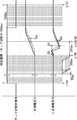
次に、本実施の形態による自動電圧調整器1の動作の具体例について、図5を用いて説明する。この具体例では、単位期間が20(ms)であり、積算期間が300(ms)であるとする。また、この具体例では、500(ms)の不感期間も含めて一次側電圧及び二次側電圧の計測が行われるものとする。また、この具体例では、計器用変圧器41の変圧比が1/60であり、調整変圧器11のタップ幅が100(V)であるとする。そのため、計器用変圧器41の出力側の電圧に換算した値が0.55(≒100/(60×3))となる閾値THを用いるものとする。また、この具体例では、タップ切替制御器14は、一般型SVRのモードと、逆送時タップ固定型SVRのモードとで動作可能であるとする。 Next, a specific example of the operation of the automatic voltage regulator 1 according to the present embodiment will be described with reference to FIG. In this specific example, it is assumed that the unit period is 20 (ms) and the integration period is 300 (ms). Further, in this specific example, it is assumed that the primary side voltage and the secondary side voltage are measured including a dead period of 500 (ms). Further, in this specific example, it is assumed that the transformation ratio of the instrument transformer 41 is 1/60 and the tap width of the adjusting transformer 11 is 100 (V). Therefore, it is assumed that the threshold value TH at which the value converted to the voltage on the output side of the voltage transformer 41 for the instrument is 0.55 (≈100 / (60 × 3)) is used. Further, in this specific example, it is assumed that the tap changer controller 14 can operate in the mode of the general type SVR and the mode of the tap changer fixed type SVR at the time of reverse feed.
まず、タップ切替制御器14が一般型SVRのモードで操作している際に、逆潮流検出器13によって逆潮流が検出されたとする。また、その後に、タップ切替制御器14が、二次側の電圧を調整するためにタップ切替指令をタップ切替器12に出力したとする。すると、タップ切替器12は、そのタップ切替指令に応じて、タップ切替中信号をハイレベルに遷移させる。そのタップ切替中信号の立ち上がりに応じて、判定部23は、逆潮流が検出され、また、通電タップが切り替え中であると判断し、電圧計測器21,22に、単位期間(20ms)ごとの一次側電圧と二次側電圧とのサンプリングを開始させる(ステップS101,S102)。その結果、電圧計測器21において、一次側電圧V1(t0),V1(t1),V1(t2),…が計測され、また、電圧計測器22において、二次側電圧V2(t0),V2(t1),V2(t2),…が計測される(ステップS103)。電圧計測器21,22は、タップ切替中信号がハイレベルである期間と、それに続く500(ms)の不感期間とを含む判定期間において、一次側電圧及び二次側電圧のサンプリングを行う。なお、図5の一次側電圧V1及び二次側電圧V2に関し、実線で示されているのが移動平均前の電圧であり、破線で示されているのが移動平均後の電圧である。以後の変化量の算出や積算値の算出等は、その移動平均後の値を用いて行われる。 First, it is assumed that the reverse power flow is detected by the reverse
次に、積算器51は、電圧計測器21によってサンプリングされた一次側電圧V1(t0),V1(t1),V1(t2),…,V1(tZ)を用いて、単位期間ごとの電圧の変化量の絶対値ΔV11,ΔV12,…,ΔV1Zを算出する。また、積算器52は、電圧計測器22によってサンプリングされた二次側電圧V2(t0),V2(t1),V2(t2),…,V2(tZ)を用いて、単位期間ごとの電圧の変化量の絶対値ΔV21,ΔV22,…,ΔV2Zを算出する(ステップS104)。 Next, the
その後、積算器51は、単位期間ごとの電圧の変化量の絶対値ΔV11,ΔV12,…,ΔV1Zを用いて、一次側電圧変化量の積算値Σ1ΔV1,Σ2ΔV1,…,ΣZ-14ΔV1を算出する。また、積算器52は、単位期間ごとの電圧の変化量の絶対値ΔV21,ΔV22,…,ΔV2Zを用いて、二次側電圧変化量の積算値Σ1ΔV2,Σ2ΔV2,…,ΣZ-14ΔV2を算出する(ステップS105)。After that, the
なお、図5で示されるように、時刻t=tNから負荷変動が発生したとする。その負荷変動の影響は、一次側と二次側とにおいて同程度になる。また、時刻t=tNからt(N+15)の積分期間において、タップ切替による電圧変化も生じたとする。その電圧変化は、主に二次側にのみ生じている。図5から明らかなように、時刻t=tNからt(N+15)の積分期間における一次側電圧変化量の積算値ΣN+1ΔV1は、D1となる。また、その積分期間における二次側電圧変化量の積算値ΣN+1ΔV2は、D2+D3+D4となる。ここで、D2は、時刻t=tNからt(N+6)までの積算値であり、D3は、時刻t=t(N+6)からt(N+11)までの積算値であり、D4は、時刻t=t(N+11)からt(N+15)までの積算値である。As shown in FIG. 5, it is assumed that the load fluctuation occurs from the time t = tN. The effect of the load fluctuation is about the same on the primary side and the secondary side. Further, it is assumed that a voltage change due to tap switching also occurs during the integration period from time t = tN to t (N + 15). The voltage change occurs mainly only on the secondary side. As is clear from FIG. 5, the integrated value ΣN + 1 ΔV1 of the amount of change in the primary voltage during the integration period from time t = tN to t (N + 15) is D1. Further, the integrated value ΣN + 1 ΔV2 of the amount of change in the secondary voltage during the integration period is D2 + D3 + D4. Here, D2 is an integrated value from time t = tN to t (N + 6), D3 is an integrated value from time t = t (N + 6) to t (N + 11), and D4 is time t =. It is an integrated value from t (N + 11) to t (N + 15).
差算出器53は、積算器51によって算出された一次側電圧変化量の積算値Σ1ΔV1,Σ2ΔV1,…,ΣZ-14ΔV1と、積算器52によって算出された二次側電圧変化量の積算値Σ1ΔV2,Σ2ΔV2,…,ΣZ-14ΔV2とを用いて、積算期間ごとに、両者の差である電圧変化量差ΔΣV1,ΔΣV2,…,ΔΣV(Z−14)を算出する(ステップS106)。The
なお、図5の時刻t=tNからt(N+15)の積分期間については、ΔΣV(N+1)=D1−D2−D3−D4≒−D3となる。負荷変動による電圧変化よりも、通電タップの切り替えによる電圧変化の方が大きいからである。 For the integration period from time t = tN to t (N + 15) in FIG. 5, ΔΣV (N + 1) = D1-D2-D3-D4≈-D3. This is because the voltage change due to the switching of the energizing tap is larger than the voltage change due to the load fluctuation.
判定器54は、差算出器53によって算出された電圧変化量差ΔΣV1,ΔΣV2,…,ΔΣV(Z−14)のうち、絶対値が最大のものを特定する(ステップS107)。ここでは、ΔΣV(N+1)が特定されたとする。その電圧変化量差は、THより大きくないが、−THよりも小さかったとする(ステップS108,S111)。すると、判定器54は、送電方向が順送電であると判定し、その判定結果をタップ切替制御器14に出力する(ステップS112)。また、判定器54は、その判定結果を最新の判定結果として記録媒体に蓄積する(ステップS110)。このようにして、送電方向を判定する一連の処理が終了となる。 The
タップ切替制御器14は、判定結果を受け取ると、その判定結果に応じて、一般型SVRのモードを継続することになる。なお、判定器54によって、送電方向が逆送電であると判定された場合(ステップS109)には、タップ切替制御器14は、動作モードを逆送時タップ固定型SVRのモードに切り替える。その結果、逆潮流が発生しているため、調整変圧器11の通電タップは固定されることになる。また、絶対値が最大である電圧変化量差の絶対値が、THよりも小さい場合には、前回の判定結果と同じ判定が行われる(ステップS113)。その結果、不確定な測定結果に基づいて、不適切なタップ切替が行われることを回避することができるようになる。 Upon receiving the determination result, the tap changer controller 14 continues the mode of the general type SVR according to the determination result. When the
また、タップ切替制御器14は、タップ切替中信号がローレベルになってから不感期間(500ms)が終わるまでは、電圧調整が必要な状況になっても、タップ切替指令をタップ切替器12に出力しないものとする。その結果、電圧動揺が残っている状況において再度の通電タップの切り替えが行われないようにすることができ、誤判定を回避できる。 Further, the tap changer controller 14 sends a tap changer command to the
以上のように、本実施の形態による自動電圧調整器1によれば、通電タップを切り替えた後の電圧動揺が残っている状況においては、再度の通電タップの切り替えが行われないようにすることができる。その結果、送電方向の判定において、その電圧動揺に起因する誤判定を回避することができ、判定の精度を向上させることができる。また、一次側電圧の変化量に関する第1の値と、二次側電圧の変化量に関する第2の値とを比較する際に、閾値を用いて大小関係を判断することにより、第1及び第2の値が近い状況において、誤判定を行うことを回避することができる。また、その閾値として、計器用変圧器41の出力側の電圧に変換した値が、調整変圧器11のタップ幅×計器用変圧器41の変圧比/3となるものを用いることによって、第1及び第2の値の小さい方の値が大きい方の値の半分よりも大きい場合のように、両者が近似している場合には、第1及び第2の値の大小関係を用いた判定を行わないようにすることができ、誤判定を適切に回避することができる。 As described above, according to the automatic voltage regulator 1 according to the present embodiment, in the situation where the voltage fluctuation remains after the energization tap is switched, the energization tap is not switched again. Can be done. As a result, in the determination of the power transmission direction, it is possible to avoid an erroneous determination due to the voltage fluctuation, and it is possible to improve the accuracy of the determination. Further, when comparing the first value regarding the amount of change in the primary side voltage and the second value regarding the amount of change in the secondary side voltage, the first and first values are determined by determining the magnitude relationship using the threshold value. It is possible to avoid making an erroneous determination in a situation where the values of 2 are close to each other. Further, as the threshold value, the value converted into the voltage on the output side of the voltage transformer 41 is the tap width of the adjusting transformer 11 × the transformation ratio of the voltage transformer 41 / 3, so that the first value is obtained. And when the smaller value of the second value is larger than half of the larger value, and when both are similar, the judgment using the magnitude relationship of the first and second values is performed. It can be prevented from being performed, and erroneous determination can be appropriately avoided.
なお、本実施の形態では、判定器54が、第1及び第2の値の大小関係を判断する際に、閾値を用いる場合について説明したが、そうでなくてもよい。判定器54は、閾値を用いないで、すなわち上記閾値を0として判定を行ってもよい。その場合には、判定器54は、例えば、第1及び第2の値の大小関係を判断する際に、第1の値が第2の値よりも大きい場合に、逆送電と判定し、第2の値が第1の値よりも大きい場合に、順送電と判定してもよい。その場合であっても、不感期間が設定されることによって、誤判定の可能性を低減することができる。 In the present embodiment, the case where the
また、本実施の形態では、不感期間が設定され、その不感期間においては通電タップの切り替えが行われない場合について説明したが、そうでなくてもよい。すなわち、不感期間の設定が行われなくてもよい。そのような場合であっても、第1及び第2の値の大小関係を判断する際に閾値が用いられることによって、誤判定の可能性を低減することができる。 Further, in the present embodiment, the case where the dead period is set and the energizing tap is not switched during the dead period has been described, but it is not necessary. That is, the dead period may not be set. Even in such a case, the possibility of erroneous determination can be reduced by using the threshold value when determining the magnitude relationship between the first and second values.
また、上記のように、第1及び第2の値は、積算値でなくてもよい。第1及び第2の値が積算値でない場合には、判定部23は、例えば、逆潮流が検出され、通電タップが切り替えられる際に、単位期間ごとに計測された一次側電圧の変化量である第1の値と、単位期間ごとに計測された二次側電圧の変化量である第2の値との大小関係を用いて、送電方向の判定を行ってもよい。その処理の詳細については、例えば、上記特許文献1を参照されたい。 Further, as described above, the first and second values do not have to be integrated values. When the first and second values are not integrated values, the
また、本実施の形態では、タップ切替器12から出力されるタップ切替中信号を用いて、通電タップが切り替え中であるかどうかが判断される場合について説明したが、そうでなくてもよい。他の方法を用いて、通電タップが切り替え中であるかどうかが判断されてもよい。例えば、通電タップを切り替えるモータが駆動中であるかどうかに応じて通電タップが切り替え中であるかどうかが判断されてもよい。 Further, in the present embodiment, the case where it is determined whether or not the energizing tap is being switched by using the tap switching signal output from the
また、本実施の形態では、電力の逆潮流が検出された際に送電方向の判定を行う場合について主に説明したが、そうでなくてもよいことは上記のとおりである。逆潮流が検出されたかどうかに関わらず、送電方向の判定を行う場合には、自動電圧調整器1は、逆潮流検出器13を備えていなくてもよい。なお、自動電圧調整器1が逆潮流検出器13を備えていない場合には、タップ切替制御器14は、判定部23による判定結果を用いたタップ切替器12の制御を行ってもよい。すなわち、タップ切替制御器14は、順潮流、逆潮流の検出結果に代えて、順送電、逆送電の判定結果を用いて制御を行ってもよい。具体的には、逆送時タップ固定型SVRの場合には、タップ切替制御器14は、順送電と判定されたときには二次側電圧を調整するように制御し、逆送電と判定されたときには通電タップが固定されるように制御してもよい。また、完全逆送型のSVRの場合には、タップ切替制御器14は、順送電と判定されたときには二次側電圧を調整するように制御し、逆送電と判定されたときには一次側電圧を調整するように制御してもよい。このような制御が行われることによって、例えば、逆送電時に順潮流となっている場合にも、自動電圧調整器1において適切な電圧調整が行われるようになる。 Further, in the present embodiment, the case where the power transmission direction is determined when the reverse power flow of electric power is detected has been mainly described, but it is not necessary as described above. When determining the power transmission direction regardless of whether reverse power flow is detected, the automatic voltage regulator 1 does not have to include the reverse
また、上記実施の形態において、各処理または各機能は、単一の装置または単一のシステムによって集中処理されることによって実現されてもよく、または、複数の装置または複数のシステムによって分散処理されることによって実現されてもよい。 Further, in the above embodiment, each process or each function may be realized by centralized processing by a single device or a single system, or distributed processing by a plurality of devices or a plurality of systems. It may be realized by.
また、上記実施の形態において、各構成要素間で行われる情報の受け渡しは、例えば、その情報の受け渡しを行う2個の構成要素が物理的に異なるものである場合には、一方の構成要素による情報の出力と、他方の構成要素による情報の受け付けとによって行われてもよく、または、その情報の受け渡しを行う2個の構成要素が物理的に同じものである場合には、一方の構成要素に対応する処理のフェーズから、他方の構成要素に対応する処理のフェーズに移ることによって行われてもよい。 Further, in the above embodiment, the transfer of information performed between the respective components depends on, for example, one of the components when the two components that transfer the information are physically different. It may be performed by outputting information and accepting information by the other component, or if the two components that pass the information are physically the same, one component. It may be performed by moving from the processing phase corresponding to the above to the processing phase corresponding to the other component.
また、上記実施の形態で説明した各構成要素のうち、ソフトウェアにより実現可能な構成要素については、プログラムを実行することによって実現されてもよい。例えば、ハードディスクや半導体メモリ等の記録媒体に記録されたソフトウェア・プログラムをCPU等のプログラム実行部が読み出して実行することによって、各構成要素が実現され得る。その実行時に、プログラム実行部は、記憶部や記録媒体にアクセスしながらプログラムを実行してもよい。また、そのプログラムは、サーバなどからダウンロードされることによって実行されてもよく、所定の記録媒体(例えば、磁気ディスクや半導体メモリなど)に記録されたプログラムが読み出されることによって実行されてもよい。 Further, among the components described in the above-described embodiment, the components that can be realized by software may be realized by executing the program. For example, each component can be realized by a program execution unit such as a CPU reading and executing a software program recorded on a recording medium such as a hard disk or a semiconductor memory. At the time of execution, the program execution unit may execute the program while accessing the storage unit or the recording medium. Further, the program may be executed by being downloaded from a server or the like, or may be executed by reading a program recorded on a predetermined recording medium (for example, a magnetic disk, a semiconductor memory, etc.).
また、本発明は、以上の実施の形態に限定されることなく、種々の変更が可能であり、それらも本発明の範囲内に包含されるものであることは言うまでもない。 Further, it goes without saying that the present invention is not limited to the above embodiments, and various modifications can be made, and these are also included in the scope of the present invention.
以上より、本発明による自動電圧調整器等によれば、誤判定を低減できるという効果が得られ、二次側の分散型電源に起因する逆潮流にも対応可能な自動電圧調整器等として有用である。 From the above, the automatic voltage regulator or the like according to the present invention has the effect of reducing erroneous determination, and is useful as an automatic voltage regulator or the like that can cope with reverse power flow caused by the distributed power source on the secondary side. Is.
1 自動電圧調整器
2 送電方向判定装置
11 調整変圧器
12 タップ切替器
13 逆潮流検出器
14 タップ切替制御器
21、22 電圧計測器
23 判定部
41 計器用変圧器
51、52 積算器
53 差算出器
54 判定器1 Automatic voltage regulator 2 Transmission direction determination device 11
Claims (7)
Translated fromJapanese前記自動電圧調整器が有する調整変圧器の一次側及び二次側の単位期間ごとの電圧に移動平均処理を行うことによって一次側及び二次側の電圧を計測する電圧計測器と、
前記自動電圧調整器において通電タップが切り替えられる際に、順送電または逆送電と判定する判定部と、を備え、
前記判定部は、
前記電圧計測器によって単位期間ごとに計測された前記調整変圧器の一次側電圧及び二次側電圧のそれぞれについて、当該単位期間ごとの電圧の変化量の絶対値を所定の積算期間において積算することによって、一次側電圧変化量の積算値及び二次側電圧変化量の積算値を積算期間ごとに取得する積算器と、
各積算期間について、一次側電圧変化量の積算値と二次側電圧変化量の積算値との差である電圧変化量差を算出する差算出器と、
前記差算出器によって積算期間ごとに算出された複数の電圧変化量差における絶対値が最大の電圧変化量差に対応する積算期間において、第1の値である一次側電圧変化量の積算値が第2の値である二次側電圧変化量の積算値よりも大きい場合に、逆送電と判定し、二次側電圧変化量の積算値が一次側電圧変化量の積算値よりも大きい場合に、順送電と判定する判定器と、を備え、
前記判定器は、前記第1及び第2の値の大小関係を判断する際に、第1の値が第2の値よりも閾値を超えて大きい場合に、第1の値が第2の値よりも大きいと判断し、第2の値が第1の値よりも前記閾値を超えて大きい場合に、第2の値が第1の値よりも大きいと判断し、第1の値と第2の値との差の絶対値が前記閾値より小さい場合に、前回の判定結果と同じ判定とする、送電方向判定装置。It is a power transmission direction determination device that determines the power transmission direction in an automatic voltage regulator.
A voltage measuring instrument that measures the voltage on the primary side and the secondary side by performing a moving average process on the voltage for each unit period of the primary side and the secondary side of the adjusting transformer of the automatic voltage regulator.
The automatic voltage regulator is provided with a determination unit for determining forward power transmission or reverse power transmission when the energizing tap is switched.
The determination unit
For each of the primary side voltage and the secondary side voltage of the adjusting transformer measured by the voltage measuring instrument for each unit period, the absolute value of the amount of change in the voltage for each unit period shall be integrated in a predetermined integration period. An integrator that acquires the integrated value of the primary side voltage change amount and the integrated value of the secondary side voltage change amount for each integration period.
For each integration period, a difference calculator that calculates the voltage change amount difference, which is the difference between the integrated value of the primary side voltage change amount and the integrated value of the secondary side voltage change amount,
In the integration period corresponding to the maximum voltage change amount difference in the plurality of voltage change amount differences calculated for each integration period by the difference calculator, the integrated value of the primary side voltage change amount, which is the first value, is When it is larger than the integrated value of the secondary voltage change amount, which is the second value, it is judged as reverse power transmission, and when the integrated value of the secondary side voltage change amount is larger than the integrated value of the primary side voltage change amount. , Equipped with a judgment device that determines forward power transmission,
When the determination device determines the magnitude relationship between the first and second values, the first value is the second value when the first value is larger than the second value by a threshold value. When the second value is larger than the first value by exceeding the threshold value, it is determined that the second value is larger than the first value, and the first value and the second value are determined to be larger than the first value. A power transmission direction determination devicethat makes the same determination as the previous determination result when the absolute value of the difference from the value of is smaller than the threshold value .
前記閾値は、前記計器用変圧器の出力側の電圧に換算した値が、
前記調整変圧器のタップ幅×当該計器用変圧器の変圧比/3
となるものである、請求項1または請求項2記載の送電方向判定装置。The voltage measuring instrument has a voltage transformer.
The threshold value is a value converted into a voltage on the output side of the voltage transformer.
Tap width of the adjustment transformer x transformer ratio of the instrument transformer / 3
The power transmission direction determination device according to claim1 or 2.
前記調整変圧器の通電タップを切り替えるタップ切替器と、
前記調整変圧器の一次側及び二次側の単位期間ごとの電圧に移動平均処理を行うことによって一次側及び二次側の電圧を計測する電圧計測器と、
前記調整変圧器の電圧の計測結果に応じて前記タップ切替器を制御するタップ切替制御器と、
前記タップ切替器によって通電タップが切り替えられる際に、順送電または逆送電と判定する判定部と、を備え、
前記判定部は、
前記電圧計測器によって単位期間ごとに計測された前記調整変圧器の一次側電圧及び二次側電圧のそれぞれについて、当該単位期間ごとの電圧の変化量の絶対値を所定の積算期間において積算することによって、一次側電圧変化量の積算値及び二次側電圧変化量の積算値を積算期間ごとに取得する積算器と、
各積算期間について、一次側電圧変化量の積算値と二次側電圧変化量の積算値との差である電圧変化量差を算出する差算出器と、
前記差算出器によって積算期間ごとに算出された複数の電圧変化量差における絶対値が最大の電圧変化量差に対応する積算期間において、第1の値である一次側電圧変化量の積算値が第2の値である二次側電圧変化量の積算値よりも大きい場合に、逆送電と判定し、二次側電圧変化量の積算値が一次側電圧変化量の積算値よりも大きい場合に、順送電と判定する判定器と、を備え、
前記タップ切替制御器は、前記判定部による判定結果を用いて前記タップ切替器を制御し、
前記判定器は、前記第1及び第2の値の大小関係を判断する際に、第1の値が第2の値よりも閾値を超えて大きい場合に、第1の値が第2の値よりも大きいと判断し、第2の値が第1の値よりも前記閾値を超えて大きい場合に、第2の値が第1の値よりも大きいと判断し、第1の値と第2の値との差の絶対値が前記閾値より小さい場合に、前回の判定結果と同じ判定とする、自動電圧調整器。With an adjustable transformer with multiple taps,
A tap changer that switches the energizing tap of the adjustment transformer and
A voltage measuring instrument that measures the voltage on the primary side and the secondary side by performing a moving average process on the voltage for each unit period on the primary side and the secondary side of the adjusting transformer.
A tap changer that controls the tap changer according to the voltage measurement result of the adjustment transformer, and a tap changer controller.
A determination unit for determining forward power transmission or reverse power transmission when the energizing tap is switched by the tap changer is provided.
The determination unit
For each of the primary side voltage and the secondary side voltage of the adjusting transformer measured by the voltage measuring instrument for each unit period, the absolute value of the amount of change in the voltage for each unit period shall be integrated in a predetermined integration period. An integrator that acquires the integrated value of the primary side voltage change amount and the integrated value of the secondary side voltage change amount for each integration period.
For each integration period, a difference calculator that calculates the voltage change amount difference, which is the difference between the integrated value of the primary side voltage change amount and the integrated value of the secondary side voltage change amount,
In the integration period corresponding to the maximum voltage change amount difference in the plurality of voltage change amount differences calculated for each integration period by the difference calculator, the integrated value of the primary side voltage change amount, which is the first value, is When it is larger than the integrated value of the secondary voltage change amount, which is the second value, it is judged as reverse power transmission, and when the integrated value of the secondary side voltage change amount is larger than the integrated value of the primary side voltage change amount. , Equipped with a judgment device that determines forward power transmission,
The tap changer controller controls the tap changer using the determination result by the determination unit.
When the determination device determines the magnitude relationship between the first and second values, the first value is the second value when the first value is larger than the second value by a threshold value. When the second value is larger than the first value by exceeding the threshold value, it is determined that the second value is larger than the first value, and the first value and the second value are determined to be larger than the first value. An automatic voltage regulatorthat makes the same determination as the previous determination result when the absolute value of the difference from the value of is smaller than the threshold value .
前記閾値は、前記計器用変圧器の出力側の電圧に換算した値が、
前記調整変圧器のタップ幅×当該計器用変圧器の変圧比/3
となるものである、請求項4または請求項5記載の自動電圧調整器。The voltage measuring instrument has a voltage transformer.
The threshold value is a value converted into a voltage on the output side of the voltage transformer.
Tap width of the adjustment transformer x transformer ratio of the instrument transformer / 3
The automatic voltage regulator according to claim4 or 5.
Priority Applications (1)
| Application Number | Priority Date | Filing Date | Title |
|---|---|---|---|
| JP2017090139AJP6814692B2 (en) | 2017-04-28 | 2017-04-28 | Automatic voltage regulator and power transmission direction determination device |
Applications Claiming Priority (1)
| Application Number | Priority Date | Filing Date | Title |
|---|---|---|---|
| JP2017090139AJP6814692B2 (en) | 2017-04-28 | 2017-04-28 | Automatic voltage regulator and power transmission direction determination device |
Related Parent Applications (1)
| Application Number | Title | Priority Date | Filing Date |
|---|---|---|---|
| JP2017027111ADivisionJP6212229B1 (en) | 2017-02-16 | 2017-02-16 | Automatic voltage regulator and power transmission direction determination device |
Publications (3)
| Publication Number | Publication Date |
|---|---|
| JP2018133982A JP2018133982A (en) | 2018-08-23 |
| JP2018133982A5 JP2018133982A5 (en) | 2019-12-19 |
| JP6814692B2true JP6814692B2 (en) | 2021-01-20 |
Family
ID=63249925
Family Applications (1)
| Application Number | Title | Priority Date | Filing Date |
|---|---|---|---|
| JP2017090139AActiveJP6814692B2 (en) | 2017-04-28 | 2017-04-28 | Automatic voltage regulator and power transmission direction determination device |
Country Status (1)
| Country | Link |
|---|---|
| JP (1) | JP6814692B2 (en) |
Families Citing this family (2)
| Publication number | Priority date | Publication date | Assignee | Title |
|---|---|---|---|---|
| JP7253664B1 (en)* | 2022-11-22 | 2023-04-06 | 株式会社ダイヘン | Judgment method and voltage regulator |
| JP7583891B1 (en) | 2023-10-20 | 2024-11-14 | 株式会社ダイヘン | Voltage Regulator |
Family Cites Families (6)
| Publication number | Priority date | Publication date | Assignee | Title |
|---|---|---|---|---|
| JP2011257219A (en)* | 2010-06-08 | 2011-12-22 | Nissan Motor Co Ltd | Internal resistance of secondary battery and calculation device for calculating open voltage |
| JP5592290B2 (en)* | 2011-03-01 | 2014-09-17 | 株式会社日立製作所 | Distribution system voltage regulator and power control system |
| JP2013192378A (en)* | 2012-03-14 | 2013-09-26 | Daihen Corp | Method and device for determining cause of reverse power flow of automatic voltage regulator for power distribution |
| JP6161880B2 (en)* | 2012-07-27 | 2017-07-12 | 株式会社キューヘン | Automatic voltage regulator and control method thereof |
| JP6069060B2 (en)* | 2013-03-22 | 2017-01-25 | 株式会社東光高岳 | Automatic voltage regulator power transmission state determination device and power transmission state determination method |
| JP5782208B1 (en)* | 2015-05-29 | 2015-09-24 | 北芝電機株式会社 | Electricity station direction determination device |
- 2017
- 2017-04-28JPJP2017090139Apatent/JP6814692B2/enactiveActive
Also Published As
| Publication number | Publication date |
|---|---|
| JP2018133982A (en) | 2018-08-23 |
Similar Documents
| Publication | Publication Date | Title |
|---|---|---|
| US7663341B2 (en) | System for controlling voltage balancing in a plurality of lithium-ion cell battery packs and method thereof | |
| CN101340090B (en) | Method of determining voltage stability margin for load shedding within an electrical power system | |
| EP3271994B1 (en) | A method for operating a battery charger, and a battery charger | |
| CA2591791C (en) | System for controlling voltage balancing in a plurality of litium-ion cell battery packs and method thereof | |
| KR20180127958A (en) | Microcontroller with digital delay line analog-to-digital converter | |
| JP6814692B2 (en) | Automatic voltage regulator and power transmission direction determination device | |
| US7110273B2 (en) | Inverter controlling method | |
| JP2018169237A (en) | Power storage control device, power storage control system, server, power storage control method, and program | |
| JP2013192378A (en) | Method and device for determining cause of reverse power flow of automatic voltage regulator for power distribution | |
| JP6212229B1 (en) | Automatic voltage regulator and power transmission direction determination device | |
| US8095246B2 (en) | System and method for automatically determining temperature tolerance range | |
| JP2018169238A (en) | Power storage controller, power storage control system, server, power storage control method, and program | |
| KR20190043297A (en) | Apparatus for controlling voltage regulation based on voltage measurement, Method thereof, and Computer readable storage medium having the same | |
| JP4247127B2 (en) | RMS voltage calculator | |
| JP2009025285A (en) | Watt meter | |
| JP2004219126A (en) | Method of automatically changing current range | |
| JP3969579B2 (en) | Electromagnetic flow meter | |
| JP2002090406A (en) | Constant-current and constant-resistance electronic load device | |
| US9279859B2 (en) | Control circuit for determining a charge current of a battery | |
| JP6755812B2 (en) | Phase voltage calculator and automatic voltage regulator | |
| JP6677910B2 (en) | Power supply for vehicle | |
| EP4415244A1 (en) | Power conversion device, and method for determining degradation of smoothing capacitor | |
| JP2006300717A (en) | Insulation resistance tester | |
| EP3839522B1 (en) | Current measurement compensation for harmonics | |
| JPH09133773A (en) | Wide-area neutron instrumentation mode switching device |
Legal Events
| Date | Code | Title | Description |
|---|---|---|---|
| A521 | Request for written amendment filed | Free format text:JAPANESE INTERMEDIATE CODE: A523 Effective date:20171019 | |
| A521 | Request for written amendment filed | Free format text:JAPANESE INTERMEDIATE CODE: A523 Effective date:20191108 | |
| A621 | Written request for application examination | Free format text:JAPANESE INTERMEDIATE CODE: A621 Effective date:20191114 | |
| A977 | Report on retrieval | Free format text:JAPANESE INTERMEDIATE CODE: A971007 Effective date:20200812 | |
| A131 | Notification of reasons for refusal | Free format text:JAPANESE INTERMEDIATE CODE: A131 Effective date:20200818 | |
| A521 | Request for written amendment filed | Free format text:JAPANESE INTERMEDIATE CODE: A523 Effective date:20201008 | |
| TRDD | Decision of grant or rejection written | ||
| A01 | Written decision to grant a patent or to grant a registration (utility model) | Free format text:JAPANESE INTERMEDIATE CODE: A01 Effective date:20201201 | |
| A61 | First payment of annual fees (during grant procedure) | Free format text:JAPANESE INTERMEDIATE CODE: A61 Effective date:20201221 | |
| R150 | Certificate of patent or registration of utility model | Ref document number:6814692 Country of ref document:JP Free format text:JAPANESE INTERMEDIATE CODE: R150 | |
| R250 | Receipt of annual fees | Free format text:JAPANESE INTERMEDIATE CODE: R250 | |
| R250 | Receipt of annual fees | Free format text:JAPANESE INTERMEDIATE CODE: R250 |