JP6812661B2 - Faucet device - Google Patents
Faucet deviceDownload PDFInfo
- Publication number
- JP6812661B2 JP6812661B2JP2016097263AJP2016097263AJP6812661B2JP 6812661 B2JP6812661 B2JP 6812661B2JP 2016097263 AJP2016097263 AJP 2016097263AJP 2016097263 AJP2016097263 AJP 2016097263AJP 6812661 B2JP6812661 B2JP 6812661B2
- Authority
- JP
- Japan
- Prior art keywords
- light
- light receiving
- receiving element
- control unit
- polarized light
- Prior art date
- Legal status (The legal status is an assumption and is not a legal conclusion. Google has not performed a legal analysis and makes no representation as to the accuracy of the status listed.)
- Active
Links
- XLYOFNOQVPJJNP-UHFFFAOYSA-NwaterSubstancesOXLYOFNOQVPJJNP-UHFFFAOYSA-N0.000claimsdescription112
- 230000010287polarizationEffects0.000claimsdescription46
- 230000003287optical effectEffects0.000claimsdescription42
- 238000006243chemical reactionMethods0.000claimsdescription25
- 238000001514detection methodMethods0.000claimsdescription20
- 230000005540biological transmissionEffects0.000description38
- 238000000034methodMethods0.000description16
- 230000008569processEffects0.000description15
- 238000010586diagramMethods0.000description14
- 238000000926separation methodMethods0.000description10
- 230000002238attenuated effectEffects0.000description9
- 239000000758substrateSubstances0.000description8
- 230000000903blocking effectEffects0.000description7
- 125000002066L-histidyl groupChemical group[H]N1C([H])=NC(C([H])([H])[C@](C(=O)[*])([H])N([H])[H])=C1[H]0.000description5
- 238000007599dischargingMethods0.000description5
- 239000012528membraneSubstances0.000description5
- 230000000694effectsEffects0.000description4
- 239000000919ceramicSubstances0.000description3
- 230000008859changeEffects0.000description2
- 239000000463materialSubstances0.000description2
- 229910001220stainless steelInorganic materials0.000description2
- 239000010935stainless steelSubstances0.000description2
- 238000002834transmittanceMethods0.000description2
- 238000010521absorption reactionMethods0.000description1
- 239000011521glassSubstances0.000description1
- 230000007246mechanismEffects0.000description1
- 230000004048modificationEffects0.000description1
- 238000012986modificationMethods0.000description1
- 239000011347resinSubstances0.000description1
- 229920005989resinPolymers0.000description1
- 230000004044responseEffects0.000description1
- 230000035945sensitivityEffects0.000description1
Images


Classifications
- E—FIXED CONSTRUCTIONS
- E03—WATER SUPPLY; SEWERAGE
- E03C—DOMESTIC PLUMBING INSTALLATIONS FOR FRESH WATER OR WASTE WATER; SINKS
- E03C1/00—Domestic plumbing installations for fresh water or waste water; Sinks
- E03C1/02—Plumbing installations for fresh water
- E03C1/05—Arrangements of devices on wash-basins, baths, sinks, or the like for remote control of taps
- E03C1/055—Electrical control devices, e.g. with push buttons, control panels or the like
- E03C1/057—Electrical control devices, e.g. with push buttons, control panels or the like touchless, i.e. using sensors
- G—PHYSICS
- G01—MEASURING; TESTING
- G01S—RADIO DIRECTION-FINDING; RADIO NAVIGATION; DETERMINING DISTANCE OR VELOCITY BY USE OF RADIO WAVES; LOCATING OR PRESENCE-DETECTING BY USE OF THE REFLECTION OR RERADIATION OF RADIO WAVES; ANALOGOUS ARRANGEMENTS USING OTHER WAVES
- G01S17/00—Systems using the reflection or reradiation of electromagnetic waves other than radio waves, e.g. lidar systems
- G01S17/02—Systems using the reflection of electromagnetic waves other than radio waves
- G01S17/04—Systems determining the presence of a target
- G—PHYSICS
- G01—MEASURING; TESTING
- G01S—RADIO DIRECTION-FINDING; RADIO NAVIGATION; DETERMINING DISTANCE OR VELOCITY BY USE OF RADIO WAVES; LOCATING OR PRESENCE-DETECTING BY USE OF THE REFLECTION OR RERADIATION OF RADIO WAVES; ANALOGOUS ARRANGEMENTS USING OTHER WAVES
- G01S17/00—Systems using the reflection or reradiation of electromagnetic waves other than radio waves, e.g. lidar systems
- G01S17/88—Lidar systems specially adapted for specific applications
- G—PHYSICS
- G01—MEASURING; TESTING
- G01S—RADIO DIRECTION-FINDING; RADIO NAVIGATION; DETERMINING DISTANCE OR VELOCITY BY USE OF RADIO WAVES; LOCATING OR PRESENCE-DETECTING BY USE OF THE REFLECTION OR RERADIATION OF RADIO WAVES; ANALOGOUS ARRANGEMENTS USING OTHER WAVES
- G01S7/00—Details of systems according to groups G01S13/00, G01S15/00, G01S17/00
- G01S7/48—Details of systems according to groups G01S13/00, G01S15/00, G01S17/00 of systems according to group G01S17/00
- G01S7/481—Constructional features, e.g. arrangements of optical elements
- G01S7/4814—Constructional features, e.g. arrangements of optical elements of transmitters alone
- G—PHYSICS
- G01—MEASURING; TESTING
- G01S—RADIO DIRECTION-FINDING; RADIO NAVIGATION; DETERMINING DISTANCE OR VELOCITY BY USE OF RADIO WAVES; LOCATING OR PRESENCE-DETECTING BY USE OF THE REFLECTION OR RERADIATION OF RADIO WAVES; ANALOGOUS ARRANGEMENTS USING OTHER WAVES
- G01S7/00—Details of systems according to groups G01S13/00, G01S15/00, G01S17/00
- G01S7/48—Details of systems according to groups G01S13/00, G01S15/00, G01S17/00 of systems according to group G01S17/00
- G01S7/481—Constructional features, e.g. arrangements of optical elements
- G01S7/4816—Constructional features, e.g. arrangements of optical elements of receivers alone
- G—PHYSICS
- G01—MEASURING; TESTING
- G01S—RADIO DIRECTION-FINDING; RADIO NAVIGATION; DETERMINING DISTANCE OR VELOCITY BY USE OF RADIO WAVES; LOCATING OR PRESENCE-DETECTING BY USE OF THE REFLECTION OR RERADIATION OF RADIO WAVES; ANALOGOUS ARRANGEMENTS USING OTHER WAVES
- G01S7/00—Details of systems according to groups G01S13/00, G01S15/00, G01S17/00
- G01S7/48—Details of systems according to groups G01S13/00, G01S15/00, G01S17/00 of systems according to group G01S17/00
- G01S7/499—Details of systems according to groups G01S13/00, G01S15/00, G01S17/00 of systems according to group G01S17/00 using polarisation effects
Landscapes
- Engineering & Computer Science (AREA)
- Physics & Mathematics (AREA)
- Remote Sensing (AREA)
- Computer Networks & Wireless Communication (AREA)
- General Physics & Mathematics (AREA)
- Radar, Positioning & Navigation (AREA)
- Electromagnetism (AREA)
- Health & Medical Sciences (AREA)
- Life Sciences & Earth Sciences (AREA)
- Hydrology & Water Resources (AREA)
- Public Health (AREA)
- Water Supply & Treatment (AREA)
- Domestic Plumbing Installations (AREA)
- Geophysics And Detection Of Objects (AREA)
Description
Translated fromJapanese本発明の態様は、一般的に、水栓装置に関する。 Aspects of the present invention generally relate to faucet devices.
使用者の手などの対象物をセンサで検出して開閉弁を駆動することにより、吐止水を自動で制御する水栓装置がある。水栓装置では、例えば、赤外光などの光信号を送信し、対象物で反射した光信号の反射信号を受信し、この反射信号の受光量が所定の閾値を超えた場合に、対象物の存在を検出し、吐水を開始する。 There is a faucet device that automatically controls spouting water by detecting an object such as a user's hand with a sensor and driving an on-off valve. In a faucet device, for example, an optical signal such as infrared light is transmitted, a reflected signal of an optical signal reflected by the object is received, and when the received amount of the reflected signal exceeds a predetermined threshold value, the object is subjected to. Detects the presence of water and starts spouting water.
このような水栓装置において、送信側及び受信側に偏光板を設けることにより、鏡面反射光の入射にともなう誤吐水を抑制することが行われている(例えば、特許文献1)。 In such a faucet device, by providing polarizing plates on the transmitting side and the receiving side, it is possible to suppress erroneous water discharge due to the incident of specularly reflected light (for example, Patent Document 1).
例えば、送信側に垂直方向の偏光板を設け、垂直方向の直線偏光光を光信号として送信するとともに、受信側に水平方向の偏光板を設け、水平方向の直線偏光光の反射信号を受信するようにする。人体の手などで光信号が反射した場合には、拡散反射となるため、この場合の反射信号には、水平方向の直線偏光の成分も含まれる。このため、水平方向の偏光板を透過し、反射信号が受信される。一方、洗面器やシンクなどで光信号が鏡面反射した場合には、実質的に垂直方向の直線偏光の成分のみを有する反射信号が水平方向の偏光板に入射するため、偏光板に遮断され、反射信号が受信されなくなる。これにより、鏡面反射光の入射にともなう誤吐水が抑制される。 For example, a vertical polarizing plate is provided on the transmitting side to transmit the linearly polarized light in the vertical direction as an optical signal, and a horizontal polarizing plate is provided on the receiving side to receive the reflected signal of the linearly polarized light in the horizontal direction. To do so. When an optical signal is reflected by a human hand or the like, it becomes diffuse reflection. Therefore, the reflected signal in this case also includes a component of linear polarization in the horizontal direction. Therefore, the reflected signal is received through the polarizing plate in the horizontal direction. On the other hand, when the optical signal is specularly reflected by a washbasin or a sink, the reflected signal having substantially only the linearly polarized light component in the vertical direction is incident on the polarizing plate in the horizontal direction, so that the light signal is blocked by the polarizing plate. The reflected signal is no longer received. As a result, erroneous water discharge due to the incident of specularly reflected light is suppressed.
しかしながら、原理上、偏光板を透過した光は、約50%減衰する。従って、送信側及び受信側に偏光板を設ける構成では、送信側で約50%減衰し、受信側でさらに約50%減衰し、合計で約25%に減衰してしまう。すなわち、2つの偏光板を設けることにより、光信号の強度が約75%も失われていることになる。このため、偏光板を用いない場合と同程度の受光量を得ようとすると、送信時の光の強度(発光パワー)を約4倍にする必要がある。光の強度を上げるためには、例えば、投光素子に供給する電流を大きくする必要があり、消費電力の増加を招いてしまう。水栓装置では、電源に接続したまま対象物の検出を常時行うことが多く、誤吐水の抑制とともに、低消費電力化も求められている。 However, in principle, the light transmitted through the polarizing plate is attenuated by about 50%. Therefore, in the configuration in which the polarizing plates are provided on the transmitting side and the receiving side, the attenuation is about 50% on the transmitting side and further attenuated by about 50% on the receiving side, resulting in a total attenuation of about 25%. That is, by providing the two polarizing plates, the intensity of the optical signal is lost by about 75%. Therefore, in order to obtain the same amount of received light as when the polarizing plate is not used, it is necessary to increase the light intensity (emission power) at the time of transmission by about four times. In order to increase the intensity of light, for example, it is necessary to increase the current supplied to the light projecting element, which causes an increase in power consumption. In faucet devices, objects are often detected while connected to a power source, and it is required to suppress accidental water discharge and reduce power consumption.
このため、対象物を検出して自動的に吐止水を制御する水栓装置では、鏡面反射による誤吐水を抑制しつつ、低消費電力化に優れた対象物の検出方式が望まれる。 For this reason, in a faucet device that detects an object and automatically controls spouting and stopping water, a method for detecting the object that is excellent in low power consumption while suppressing erroneous spouting due to specular reflection is desired.
本発明は、かかる課題の認識に基づいてなされたものであり、鏡面反射による誤吐水を抑制しつつ、低消費電力化に優れた水栓装置を提供することを目的とする。 The present invention has been made based on the recognition of such a problem, and an object of the present invention is to provide a faucet device excellent in low power consumption while suppressing erroneous water discharge due to specular reflection.
第1の発明は、水を吐出する吐水口を有する吐水部と、給水源から前記吐水口に水を導く給水路と、前記給水路を開閉する開閉弁と、光信号を送信する送信部と、前記光信号の反射信号を受信し、前記反射信号に対応した受信信号を出力する受信部と、前記受信信号を基に対象物の有無を検出し、前記対象物の検出結果に応じて前記開閉弁の開閉を制御する制御部と、を備え、前記送信部は、非偏光の光を投光する投光素子と、前記非偏光の光に含まれる第1偏光の光を透過させ、前記第1偏光と異なる偏光の光を遮断する偏光部材と、を有し、前記第1偏光の光の前記光信号を送信し、前記受信部は、前記反射信号に含まれる光を、前記第1偏光の光が鏡面反射することで形成された第2偏光の光と、前記第2偏光の光と異なる第3偏光の光と、に分割するビームスプリッタと、前記ビームスプリッタで分割された前記第2偏光の光を受光する第1受光素子と、前記ビームスプリッタで分割された前記第3偏光の光を受光する第2受光素子と、を有し、前記第1受光素子の受光量及び前記第2受光素子の受光量に対応した前記受信信号を前記制御部に出力し、前記制御部は、前記第1受光素子の受光量と前記第2受光素子の受光量との合計の受光量を基に、前記対象物の有無を検出することを特徴とする水栓装置である。The first invention comprises a spout having a spout for discharging water, a water supply channel for guiding water from a water supply source to the spout, an on-off valve for opening and closing the water supply channel, and a transmitting section for transmitting an optical signal. , The receiving unit that receives the reflected signal of the optical signal and outputs the received signal corresponding to the reflected signal, detects the presence or absence of the object based on the received signal, and determines the presence or absence of the object according to the detection result of the object. The transmission unit includes a control unit that controls the opening and closing of the on-off valve, and the transmission unit transmits the light projecting element that projects unpolarized light and the first polarized light contained in the unpolarized light. It has a polarizing member that blocks light polarized different from the first polarized light, transmits the optical signal of the first polarized light, and the receiving unit transmits the light contained in the reflected signal to the first polarized light. A beam splitter divided into a second polarized light formed by mirror-reflecting the polarized light and a third polarized light different from the second polarized light, and the second polarized light divided by the beam splitter. It has a first light receiving element that receives bipolarized light and a second light receiving element that receives the third polarized light divided by the beam splitter, and has a light receiving amount of the first light receiving element and the first light receiving element. 2 The received signal corresponding to the light receiving amount of the light receiving element is output to the control unit, and the control unit is based on the total light receiving amount of the light receiving amount of the first light receiving element and the light receiving amount of the second light receiving element. In addition, it is a faucet device characterized by detecting the presence or absence of the object.
この水栓装置によれば、受信部において、第1受光素子が第2偏光の光を受光し、第2受光素子が第3偏光の光を受光し、第1受光素子の受光量及び第2受光素子の受光量を基に、制御部が対象物の有無を検出する。これにより、1つの偏光の光のみを透過させる偏光板を用い、1つの偏光の光を1つの受光素子で受光する場合に比べて、対象物で拡散反射した光をより多く取り込むことができる。このため、2つの偏光板を用いる場合に比べて、送信時に必要となる光の強度を抑え、消費電力の増加を抑えることができる。 According to this faucet device, in the receiving unit, the first light receiving element receives the light of the second polarized light, the second light receiving element receives the light of the third polarized light, the light receiving amount of the first light receiving element and the second light receiving element. The control unit detects the presence or absence of an object based on the amount of light received by the light receiving element. As a result, a polarizing plate that transmits only one polarized light is used, and more light diffusely reflected by the object can be taken in as compared with the case where one polarized light is received by one light receiving element. Therefore, as compared with the case of using two polarizing plates, the intensity of light required for transmission can be suppressed and the increase in power consumption can be suppressed.
また、光信号が鏡面反射した場合、反射信号は、第2偏光の光となる。このため、第1受光素子の受光量を基に、鏡面反射の検出を行うこともできる。従って、鏡面反射による誤吐水を抑制しつつ、低消費電力化に優れた水栓装置を提供することができる。 When the light signal is specularly reflected, the reflected signal becomes the second polarized light. Therefore, it is possible to detect specular reflection based on the amount of light received by the first light receiving element. Therefore, it is possible to provide a faucet device excellent in low power consumption while suppressing erroneous water discharge due to specular reflection.
第2の発明は、水を吐出する吐水口を有する吐水部と、給水源から前記吐水口に水を導く給水路と、前記給水路を開閉する開閉弁と、光信号を送信する送信部と、前記光信号の反射信号を受信し、前記反射信号に対応した受信信号を出力する受信部と、前記受信信号を基に対象物の有無を検出し、前記対象物の検出結果に応じて前記開閉弁の開閉を制御する制御部と、を備え、前記送信部は、非偏光の光を投光する投光素子と、前記投光素子から投光された前記非偏光の光を第1偏光の光に変換する偏光変換素子と、を有し、前記第1偏光の光の前記光信号を送信し、前記受信部は、前記反射信号に含まれる光を、前記第1偏光の光が鏡面反射することで形成された第2偏光の光と、前記第2偏光と異なる第3偏光の光と、に分割するビームスプリッタと、前記ビームスプリッタで分割された前記第2偏光の光を受光する第1受光素子と、前記ビームスプリッタで分割された前記第3偏光の光を受光する第2受光素子と、を有し、前記第1受光素子の受光量及び前記第2受光素子の受光量に対応した前記受信信号を前記制御部に出力し、前記制御部は、前記第1受光素子の受光量と前記第2受光素子の受光量との合計の受光量を基に、前記対象物の有無を検出することを特徴とする水栓装置である。The second invention includes a spout having a spout for discharging water, a water supply channel for guiding water from the water supply source to the spout, an on-off valve for opening and closing the water supply, and a transmitting section for transmitting an optical signal. , The receiving unit that receives the reflected signal of the optical signal and outputs the received signal corresponding to the reflected signal, detects the presence or absence of the object based on the received signal, and determines the presence or absence of the object according to the detection result of the object. A control unit that controls the opening and closing of the on-off valve is provided, and the transmission unit first polarizes the light projecting element that projects unpolarized light and the non-polarized light that is projected from the light projecting element. It has a polarization conversion element that converts the light of the first polarized light, and transmits the optical signal of the first polarized light, and the receiving unit mirrors the light contained in the reflected signal. A beam splitter that divides the second polarized light formed by reflection and a third polarized light different from the second polarized light, and the second polarized light divided by the beam splitter are received. It has a first light receiving element and a second light receiving element that receives the light of the third polarized light divided by the beam splitter, and has a light receiving amount of the first light receiving element and a light receiving amount of the second light receiving element. The corresponding received signal is output to the control unit, and the control unit outputs the presence or absence of the object based on the total light receiving amount of the light receiving amount of the first light receiving element and the light receiving amount of the second light receiving element. It is a faucet device characterized by detecting.
この水栓装置によれば、非偏光の光を偏光変換素子によって第1偏光の光に変換し、第1偏光の光の光信号を送信部から送信している。偏光変換素子では、非偏光の光に含まれる第1偏光と異なる偏光の光を、第1偏光の光に変換して出力することができる。これにより、1つの偏光の光のみを透過させる偏光板を用いる場合に比べて、透過にともなう光の減衰を抑制することができ、対象物に到達する光、及び受信部における光の受光量を増加させることができる。 According to this faucet device, unpolarized light is converted into first-polarized light by a polarization conversion element, and an optical signal of the first-polarized light is transmitted from a transmission unit. In the polarization conversion element, light having a polarization different from that of the first polarized light contained in the unpolarized light can be converted into the first polarized light and output. As a result, it is possible to suppress the attenuation of light due to transmission as compared with the case of using a polarizing plate that transmits only one polarized light, and the amount of light that reaches the object and the amount of light received by the receiving unit can be reduced. Can be increased.
また、受信部において、第1受光素子が第2偏光の光を受光し、第2受光素子が第3偏光の光を受光し、第1受光素子の受光量及び第2受光素子の受光量を基に、制御部が対象物の有無を検出する。これにより、1つの偏光の光のみを透過させる偏光板を用い、1つの偏光の光を1つの受光素子で受光する場合に比べて、対象物で拡散反射した光をより多く取り込むことができる。このため、2つの偏光板を用いる場合に比べて、送信時に必要となる光の強度を抑え、消費電力の増加を抑えることができる。 Further, in the receiving unit, the first light receiving element receives the light of the second polarized light, the second light receiving element receives the light of the third polarized light, and the light receiving amount of the first light receiving element and the light receiving amount of the second light receiving element are measured. Based on this, the control unit detects the presence or absence of the object. As a result, a polarizing plate that transmits only one polarized light is used, and more light diffusely reflected by the object can be taken in as compared with the case where one polarized light is received by one light receiving element. Therefore, as compared with the case of using two polarizing plates, the intensity of light required for transmission can be suppressed and the increase in power consumption can be suppressed.
さらに、光信号が鏡面反射した場合、反射信号は、第2偏光の光となる。このため、第1受光素子の受光量を基に、鏡面反射の検出を行うこともできる。従って、鏡面反射による誤吐水を抑制しつつ、低消費電力化に優れた水栓装置を提供することができる。 Further, when the light signal is specularly reflected, the reflected signal becomes the second polarized light. Therefore, it is possible to detect specular reflection based on the amount of light received by the first light receiving element. Therefore, it is possible to provide a faucet device excellent in low power consumption while suppressing erroneous water discharge due to specular reflection.
第3の発明は、第1又は第2の発明において、前記第1受光素子と前記第2受光素子とは、1ユニット化されていることを特徴とする水栓装置である。A third invention is a faucet device according tothe first or second invention, wherein the first light receiving element and the second light receiving element are integrated into one unit.
この水栓装置によれば、部品点数を少なくすることができる。例えば、水栓装置をより小型化することができる。 According to this faucet device, the number of parts can be reduced. For example, the faucet device can be made smaller.
第4の発明は、第1〜第3の発明のいずれか1つにおいて、前記制御部は、前記第2受光素子の受光量が所定の閾値以上となった場合には、前記第1受光素子の受光量及び前記第2受光素子の受光量の少なくとも一方を基に、前記対象物の有無の検出を行うことを特徴とする水栓装置である。According to a fourth aspect of the present invention, in any one of the firstto third aspects, the control unit receives the first light receiving element when the light receiving amount of the second light receiving element becomes equal to or more than a predetermined threshold value. The faucet device is characterized in that the presence or absence of the object is detected based on at least one of the light receiving amount of the light receiving element and the light receiving amount of the second light receiving element.
この水栓装置によれば、鏡面反射による誤吐水を抑制しつつ、拡散反射による対象物の有無を適切に検出することができる。 According to this faucet device, it is possible to appropriately detect the presence or absence of an object due to diffuse reflection while suppressing erroneous water discharge due to specular reflection.
第5の発明は、第1〜第3の発明のいずれか1つにおいて、前記制御部は、前記第1受光素子の受光量が第1閾値以上であり、前記第2受光素子の受光量が第2閾値未満である場合に、前記受光部が鏡面反射光を受光したことを検出することを特徴とする水栓装置である。
According to a fifth aspect of the present invention, in any one of the firstto third inventions, the control unit has a light receiving amount of the first light receiving element of the first threshold value or more and a light receiving amount of the second light receiving element. The faucet device is characterized in that it detects that the light receiving unit receives specularly reflected light when it is less than the second threshold value.
この水栓装置によれば、鏡面反射を検出することができ、止水動作や外部報知などの諸々の安全動作の実行が可能となる。これにより、鏡面反射による誤吐水をより適切に抑制することができる。 According to this faucet device, specular reflection can be detected, and various safe operations such as water stop operation and external notification can be executed. As a result, erroneous water discharge due to specular reflection can be suppressed more appropriately.
本発明の態様によれば、鏡面反射による誤吐水を抑制しつつ、低消費電力化に優れた水栓装置が提供される。 According to the aspect of the present invention, there is provided a faucet device excellent in low power consumption while suppressing erroneous water discharge due to specular reflection.
以下、実施形態について図面を参照しつつ説明する。なお、各図面中、同様の構成要素には同一の符号を付して詳細な説明は適宜省略する。
(第1の実施形態)
図1は、第1の実施形態にかかる水栓装置を表す説明図である。
図1に表したように、水栓装置10は、対象物(人体や物体等)を検出して自動的な吐止水を行うものであり、洗面台に備え付けられる洗面器11に対して吐止水を行う。Hereinafter, embodiments will be described with reference to the drawings. In each drawing, similar components are designated by the same reference numerals and detailed description thereof will be omitted as appropriate.
(First Embodiment)
FIG. 1 is an explanatory diagram showing a faucet device according to the first embodiment.
As shown in FIG. 1, the
洗面器11は、洗面カウンタ12の上面に設けられる。洗面カウンタ12の上には、洗面器11のボウル面11aに対して水を吐出するためのスパウトを構成する水栓13(吐水部)が設けられる。水栓13は、水を吐出する吐水口13aを有し、この吐水口13aから吐出される水が洗面器11のボウル面11a内に吐出されるように設けられる。 The
水栓13が吐水口13aから吐出する水は、給水路14により供給される。給水路14は、水道管等の給水源から供給される水を吐水口13aへと導く。洗面器11には、排水路15が接続されている。排水路15は、吐水口13aから洗面器11のボウル面11a内に吐水された水を排出する。 The water discharged by the
水栓装置10は、電磁弁16(開閉弁)と、センサ部18と、制御部20とを備える。センサ部18は、制御部20と分離されている。センサ部18は、例えば、水栓13の内部に収容される。電磁弁16及び制御部20は、例えば、洗面台の下側に収容される。電磁弁16及び制御部20は、例えば、洗面カウンタ12の下方に設けられるキャビネット(図示は省略)内に収容される。 The
センサ部18と制御部20とは、接続ケーブル17で接続されている。制御部20は、例えば、接続ケーブル17を介してセンサ部18に電源電圧を供給し、接続ケーブル17を介してセンサ部18を制御する。 The
電磁弁16は、給水路14に設けられ、給水路14の開閉を行う。電磁弁16が開くと、給水路14から供給された水が吐水口13aから吐出される吐水状態となり、電磁弁16が閉じると、給水路14から供給された水が吐水口13aから吐出されない止水状態となる。 The
電磁弁16は、制御部20に接続されており、制御部20は、電磁弁16を駆動して開/閉動作を制御する。電磁弁16は、制御部20からの制御信号に従って電気的に制御され、給水路14の開閉を行う。このように、電磁弁16は、吐水口13aから吐水される水の給水路14を開閉する給水バルブとして機能する。 The
電磁弁16は、いわゆるラッチング・ソレノイド・バルブと称される自己保持型電磁弁(ラッチ式電磁弁)であり、ソレノイドコイルへの一方向への通電によって閉状態から開状態に動作(開動作)し、その後ソレノイドコイルへの通電を遮断しても開状態を保持し、ソレノイドコイルへの他方向への通電によって開状態から閉状態に動作(閉動作)し、その後ソレノイドコイルへの通電を遮断しても閉状態を保持する。給水路14の開閉は、電磁弁16に限ることなく、制御部20の制御に応じて給水路14を開閉可能な他の開閉弁機構で行ってもよい。 The
センサ部18は、吐水口13aに接近する対象物(手など)を検出する。この吐水口13aの吐水先が、センサ部18の検出領域となる。センサ部18は、光信号を送信し、送信した光信号を受けた人体等の対象物から反射した反射信号を受信することにより、対象物の位置や動き等を検出する。 The
センサ部18は、例えば、赤外光の光信号を用いた光センサである。センサ部18から送信される光信号は、例えば、可視光などでもよい。以下では、光信号を赤外光として説明を行う。なお、「赤外光」とは、例えば、0.7μm以上1000μm以下の波長の光である。 The
センサ部18は、水栓13の吐水口13a近くの内部に設けられ、洗面台の使用者側(図1において左側)に向けて光信号を送信するように配置される。これにより、センサ部18は、吐水口13aに人体が近づいてきたことや、吐水口13aに近づいた人体から吐水口13aに向けて手が差し出されたこと等を検出可能にする。 The
センサ部18は、反射信号の受信結果(対象物の検出結果)を表す受信信号を接続ケーブル17を介して制御部20に出力する。制御部20は、センサ部18から出力された受信信号に基づいて、対象物の有無を検出する。制御部20は、例えば、受信信号に基づいて、対象物の位置や動き等を検出する。そして、制御部20は、この検出結果に基づいて電磁弁16の開/閉動作を制御する。また、制御部20は、センサ部18に対して制御信号を出力して、センサ部18のセンシング動作を制御する。 The
以上のように、本実施形態の水栓装置10は、電磁弁16と、センサ部18と、制御部20とを備え、センサ部18の受信信号に基づいて制御部20が制御することにより、電磁弁16の開/閉動作が制御される。これにより、吐水口13aに接近する対象物の検出結果(洗面台の使用者の動き等)に応じた吐水を行う。制御部20は、対象物の検出に応じて吐水を行い、対象物の非検出に応じて吐水を停止させる。すなわち、水栓装置10では、使用者が吐水口13aの近くに手などを差し出している間、自動的に吐水が行われる。 As described above, the
また、センサ部18は常に動作しているのではなく、センシングを必要とするタイミングに動作をするように、制御部20が制御している。これにより、センサ部18の消費電力を下げることができる。制御部20は、例えば、使用者が不便に感じない程度にセンサ部18のセンシング動作の頻度を下げる。これにより、水栓装置10全体の低消費電力化を図ることができる。 Further, the
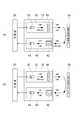
図2(a)及び図2(b)は、第1の実施形態に係る水栓装置の一部を表すブロック図である。
図2(a)及び図2(b)に表したように、センサ部18は、送信部30と、受信部40と、を有する。送信部30は、対象物の検出領域に向けて光信号を送信する。受信部40は、光信号の反射信号を受信し、反射信号に対応した受信信号を制御部20に出力する。2 (a) and 2 (b) are block diagrams showing a part of the faucet device according to the first embodiment.
As shown in FIGS. 2A and 2B, the
なお、図2(a)は、センサ部18から送信された光信号が拡散反射物2aで反射した場合を表し、図2(b)は、センサ部18から送信された光信号が鏡面反射物2bで反射した場合を表している。拡散反射物2aとは、例えば、陶器製の洗面器11などである。また、人体の手などの対象物も拡散反射物2aに含まれる。鏡面反射物2bとは、例えば、ステンレス製の洗面器11などである。また、水栓装置10をシステムキッチンに用いる場合がある。この場合、拡散反射物2aは、タイル貼りのキッチンシンクなどであり、鏡面反射物2bは、ステンレス製のキッチンシンクなどである。 Note that FIG. 2A shows a case where the light signal transmitted from the
送信部30は、投光素子32と、偏光変換素子34と、を有する。投光素子32は、非偏光の光(自然光)を投光する。投光素子32は、例えば、非偏光の赤外光を投光する。投光素子32には、例えば、LED(Light Emitting Diode)などの発光素子が用いられる。送信部30は、制御部20と電気的に接続され、制御部20の制御に基づいて、投光素子32からの赤外光の投光、及び赤外光の投光の停止を切り替える。 The
偏光変換素子34は、投光素子32の光軸上において、投光素子32の前方に設けられる。投光素子32から投光された非偏光の赤外光は、偏光変換素子34に入射する。換言すれば、投光素子32は、偏光変換素子34に向けて非偏光の赤外光を投光する。偏光変換素子34は、投光素子32から投光された非偏光の赤外光を、第1偏光の赤外光に変換する。 The
投光素子32から投光された非偏光の赤外光は、第1偏光の成分と、第1偏光と異なる偏光の成分と、を有する。第1偏光は、例えば、垂直方向の直線偏光である。この場合、第1偏光と異なる偏光は、例えば、水平方向の直線偏光である。第1偏光は、上記に限ることなく、任意の方向の直線偏光でよい。また、第1偏光と異なる偏光は、第1偏光に対して直交する方向の直線偏光に限ることなく、第1偏光の偏光方向と異なる任意の偏光方向の直線偏光でよい。以下では、第1偏光を垂直方向の直線偏光(S波)、第1偏光と異なる偏光を水平方向の直線偏光(P波)として説明を行う。なお、第1偏光は、直線偏光に限ることなく、円偏光や楕円偏光などでも同様の実施形態が可能である。第1偏光と異なる偏光は、直線偏光に限ることなく、第1偏光と異なる任意の方向の偏光でよい。 The unpolarized infrared light projected from the
偏光変換素子34は、例えば、投光素子32から投光された非偏光の赤外光に含まれるS波の成分を透過させ、投光素子32から投光された非偏光の赤外光に含まれるP波の成分をS波の赤外光に変換する。そして、偏光変換素子34は、透過したS波の成分と、P波の成分を変換して生成したS波の赤外光と、を合成させる。これにより、偏光変換素子34は、非偏光の赤外光をS波の赤外光に変換する。 The
送信部30は、偏光変換素子34によって変換されたS波の赤外光を光信号として検出領域に送信する。このように、送信部30は、S波の赤外光の光信号を送信する。 The
受信部40は、偏光板42(偏光部材)と、受光素子44と、を有する。偏光板42は、反射信号に含まれる光のうち、第1偏光の光が鏡面反射することで形成された第2偏光の光を遮断し、第2偏光と異なる第3偏光の光を透過させる。この例において、偏光板42は、反射信号に含まれるS波の成分を遮断し、反射信号に含まれるP波の成分を透過させる。偏光板42は、例えば、反射及び吸収の少なくとも一方により、S波の成分を遮断する。なお、「遮断」とは、光が完全に透過しない状態のみならず、僅かに透過している状態も含むものとする。「遮断」とは、例えば、光の透過率が10%以下の状態である。また、「透過」とは、例えば、光の透過率が80%以上の状態である。また、S波の遮断及びP波の透過は、偏光板42に限ることなく、S波の遮断及びP波の透過が可能な任意の偏光部材でよい。 The receiving
受光素子44は、偏光板42を透過したP波の赤外光を受光する。受光素子44は、例えば、受光したP波の赤外光を光電変換することにより、P波の赤外光の受光量に応じた電気信号を出力する。受光素子44には、例えば、赤外光に感度を有するフォトトランジスタやフォトダイオードが用いられる。 The
受信部40は、受光素子44の受光量に対応した受信信号を制御部20に出力する。受信部40は、例えば、受光素子44から出力された電気信号に対応した受信信号を制御部20に出力する。 The receiving
拡散反射では、様々な方向に偏光した光が混ざり合い、非偏光となる。このため、図2(a)に表したように、光信号が拡散反射物2aで反射した場合、反射信号は、P波の成分と、S波の成分と、を含む。従って、光信号が拡散反射物2aで反射した場合には、反射信号に含まれるP波の成分が偏光板42を透過し、受光素子44に入射する。これにより、人体の手などの対象物の検出が可能となる。 In diffuse reflection, light polarized in various directions is mixed and becomes unpolarized. Therefore, as shown in FIG. 2A, when the light signal is reflected by the diffuse
制御部20は、受信信号を基に、受光素子44の受光量を求め、受光素子44の受光量が所定の閾値以上となった場合に、対象物が有ると検出する。 The
また、図1に表したように、光信号が対象物で反射するまでの距離L1は、光信号が洗面器11で反射するまでの距離L2よりも短い。従って、例えば、陶器製の洗面器11などで拡散反射した反射信号のP波の成分を受光素子44が受光した場合には、対象物の場合と比べて受光量が小さくなる。このため、受光量の閾値を適切に設定することにより、対象物のみを検出し、光信号が陶器製の洗面器11などで拡散反射した場合の誤吐水を抑制することができる。 Further, as shown in FIG. 1, the distance L1 until the light signal is reflected by the object is shorter than the distance L2 until the light signal is reflected by the
一方、図2(b)に表したように、光信号が鏡面反射物2bで反射した場合には、偏光状態が維持されるため、反射信号は、概ねS波のみの状態となる。従って、反射信号が偏光板42によって遮断される。すなわち、受光素子44による鏡面反射光の受光が抑制される。これにより、鏡面反射光による誤吐水も抑制される。 On the other hand, as shown in FIG. 2B, when the light signal is reflected by the
このように、反射信号に含まれるS波の赤外光は、鏡面反射光の成分であり、反射信号に含まれるP波の赤外光は、拡散反射光の成分であると考えることができる。制御部20は、鏡面反射光の成分(第2偏光)を用いることなく、拡散反射光のみに含まれる成分(第3偏光)を用いて、対象物の有無の検出を行う。 As described above, the S wave infrared light included in the reflected signal can be considered to be a component of specular reflected light, and the P wave infrared light contained in the reflected signal can be considered to be a component of diffuse reflected light. .. The
図3は、偏光変換素子の一例を表す説明図である。
図3に表したように、偏光変換素子34は、複数の基板部50と、複数の偏光分離膜52と、複数の反射膜54と、複数の1/2波長板56と、を有する。FIG. 3 is an explanatory diagram showing an example of a polarization conversion element.
As shown in FIG. 3, the
各基板部50は、断面略平行四辺形状に形成されている。各基板部50は、一方向に並べて設けられることにより、平面状の入射面50aと、平面状の出射面50bと、を形成する。入射面50a及び出射面50bは、互いに略平行である。また、平行四辺形状の各基板部50を並べることにより、各基板部50の間には、入射面50a及び出射面50bに対して略45°傾斜した傾斜面が設けられる。各基板部50には、赤外光に対して光透過性の材料が用いられ、例えばガラスや樹脂が存在する。 Each
各偏光分離膜52及び各反射膜54のそれぞれは、各基板部50の間に交互に設けられる。従って、各偏光分離膜52及び各反射膜54は、入射面50a及び出射面50bに対して略45°傾斜している。 Each of the
各偏光分離膜52は、S波の赤外光を反射させ、P波の赤外光を透過させる。各反射膜54は、S波の赤外光及びP波の赤外光を反射させる。 Each
各1/2波長板56は、各偏光分離膜52と対向して出射面50b上に設けられている。各1/2波長板56は、直線偏光光の偏光方向を略90°回転させる。すなわち、各1/2波長板56は、S波をP波に変換し、P波をS波に変換する。 Each 1/2
上記のように構成された偏光変換素子34において、S波の成分とP波の成分とを含む非偏光の光が、各偏光分離膜52に入射すると、S波の成分は、各偏光分離膜52で反射し、各反射膜54でさらに反射して出射面50bから出射する。一方、P波の成分は、各偏光分離膜52を透過して各1/2波長板56に入射し、S波に変換されて出射する。 In the
これにより、上述のように、偏光変換素子34において、非偏光の赤外光が、S波の赤外光に変換される。なお、偏光変換素子34の構成は、上記に限ることなく、非偏光の赤外光を、S波の赤外光に変換可能な任意の構成でよい。 As a result, as described above, the unpolarized infrared light is converted into S wave infrared light in the
図4は、第1の実施形態にかかる水栓装置の動作を表すフローチャートである。
図4に表したように、水栓装置10の制御部20は、例えば、電源の投入などで動作を開始すると、所定時間の待機を行う(図4のステップS101)。所定時間は、例えば、0.5秒である。待機時間は、これに限ることなく、任意の時間でよい。FIG. 4 is a flowchart showing the operation of the faucet device according to the first embodiment.
As shown in FIG. 4, the
制御部20は、所定時間の待機を行った後、投光素子32に電流を供給することにより、投光素子32に赤外光を投光させる(図4のステップS102)。制御部20は、例えば、投光素子32にパルス状の電流(電圧)を供給することにより、投光素子32に所定回数パルス投光させる。 After waiting for a predetermined time, the
制御部20は、所定回数のパルス投光を行った後、受信部40から入力された受信信号を基に、受光素子44の受光量が所定の閾値以上か否かを判定する。より詳しくは、所定回数のパルス投光にともなう受光量の積算値が、閾値以上か否かを判定する。 After performing pulse light projection a predetermined number of times, the
制御部20は、受光量が閾値以上である場合、感知と判定する。すなわち、対象物が有ると検出する。そして、制御部20は、受光量が閾値未満である場合、非感知と判定する。すなわち、対象物が無いと検出する。 When the amount of received light is equal to or greater than the threshold value, the
制御部20は、所定回数のパルス投光にともなう今回の検出動作において、対象物を感知したか否かを判定する(図4のステップS103)。 The
制御部20は、感知したと判定した場合、止水中であるか否かを判定する(図4のステップS104)。 When the
制御部20は、止水中であると判定した場合、電磁弁16を開き、吐水を開始させた後、ステップS101の処理に戻る(図4のステップS105)。一方、制御部20は、ステップS104において吐水中であると判定した場合には、そのままステップS101の処理に戻る。 When the
制御部20は、ステップS103において非感知と判定した場合、吐水中であるか否かを判定する(図4のステップS106)。 When the
制御部20は、吐水中であると判定した場合、電磁弁16を閉じ、吐水を終了させた後、ステップS101の処理に戻る(図4のステップS107)。一方、制御部20は、ステップS106において止水中であると判定した場合には、そのままステップS101の処理に戻る。 When the
制御部20は、上記の処理を繰り返す。これにより、水栓装置10では、使用者が手などを吐水口13aに近付けることにより、吐水口13aから自動で吐水が開始され、使用者が手などを吐水口13aから遠ざけることにより、吐水口13aからの吐水が終了される。 The
本実施形態に係る水栓装置10では、非偏光の光を偏光変換素子34によってS波の赤外光に変換し、S波の赤外光の光信号を送信部30から送信している。偏光変換素子34では、非偏光の光に含まれるP波の赤外光を、S波の赤外光に変換して出力することができる。これにより、1つの偏光の光のみを透過させる偏光板を用いる場合に比べて、透過にともなう光の減衰を抑制することができ、対象物に到達する光、及び受信部40における赤外光の受光量を増加させることができる。すなわち、送信部30及び受信部40のそれぞれにおいて、2つの偏光板を用いる場合に比べて、送信時に必要となる光の強度を抑え、消費電力の増加を抑えることができる。 In the
例えば、2つの偏光板を用いる構成では、送信側で約50%減衰し、受信側でさらに約50%減衰し、受光素子に受光される光の強度が、送信時の約25%に減衰してしまう。これに対し、水栓装置10では、送信部30における赤外光の減衰を抑制することができる。例えば、受光素子44に受光される赤外光の強度を、送信時の約50%に抑えることができる。受光素子44において実質的に同じ受光量を得ようとした場合に、2つの偏光板を用いる構成に比べて、投光素子32における消費電力を約1/2に抑えることができる。換言すれば、投光素子32で必要となる発光強度を約1/2に抑えることができる。 For example, in a configuration using two polarizing plates, the transmitting side is attenuated by about 50%, the receiving side is further attenuated by about 50%, and the intensity of light received by the light receiving element is attenuated to about 25% at the time of transmission. It ends up. On the other hand, in the
また、光信号が鏡面反射した場合、反射信号は、S波の赤外光となる。この際、偏光板42がS波の赤外光を遮断することにより、鏡面反射の赤外光が受光素子44に入射することも抑制することができる。従って、鏡面反射による誤吐水を抑制しつつ、低消費電力化に優れた水栓装置10を提供することができる。 When the optical signal is specularly reflected, the reflected signal becomes S wave infrared light. At this time, since the
また、本実施形態に係る水栓装置10では、制御部20が、鏡面反射光の成分(第2偏光)を用いることなく、拡散反射光のみに含まれる成分(第3偏光)を用いて、対象物の有無の検出を行う。これにより、鏡面反射による誤吐水を適切に抑制しつつ、対象物の有無の検出を簡単な構成で行うことができる。 Further, in the
(第2の実施形態)
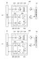
図5(a)及び図5(b)は、第2の実施形態に係る水栓装置の一部を表すブロック図である。
図5(a)及び図5(b)に表したように、水栓装置100のセンサ部118は、送信部130と、受信部140と、を有する。なお、上記第1の実施形態と機能・構成上実質的に同じものについては、同符号を付し、詳細な説明を省略する。また、図2(a)及び図2(b)と同様に、図5(a)は、センサ部118から送信された光信号が拡散反射物2aで反射した場合を表し、図5(b)は、センサ部118から送信された光信号が鏡面反射物2bで反射した場合を表している。(Second Embodiment)
5 (a) and 5 (b) are block diagrams showing a part of the faucet device according to the second embodiment.
As shown in FIGS. 5A and 5B, the
送信部130は、投光素子132と、偏光板134(偏光部材)と、を有する。投光素子132は、上記第1の実施形態の投光素子32と実質的に同じであるから、詳細な説明は、省略する。 The
偏光板134は、非偏光の光に含まれる第1偏光の光を透過させ、第1偏光と異なる偏光の光を遮断する。この例において、偏光板134は、投光素子132から投光された非偏光の赤外光に含まれるS波の成分を透過させ、投光素子132から投光された非偏光の赤外光に含まれるP波の成分を遮断する。なお、S波の透過及びP波の遮断は、偏光板134に限ることなく、S波の透過及びP波の遮断が可能な任意の偏光部材でよい。 The
このように、送信部130は、偏光板134によってP波の成分を遮断することにより、S波の赤外光を光信号として検出領域に送信する。送信部130は、S波の赤外光の光信号を送信する。 In this way, the
受信部140は、ビームスプリッタ142と、ミラー144と、第1受光素子151と、第2受光素子152と、を有する。 The receiving
ビームスプリッタ142は、反射信号に含まれる光を、第1偏光が鏡面反射することで形成された第2偏光の光と、第2偏光と異なる第3偏光の光と、に分割する。この例において、ビームスプリッタ142は、反射信号に含まれる光を、S波の赤外光とP波の赤外光とに分割する。ビームスプリッタ142は、例えば、入射面及び出射面に対して略45°傾斜して設けられた偏光分離膜142aを有し、S波を略90°反射させ、P波を透過させることにより、S波とP波とを分割する。上記とは反対に、S波を透過させ、P波を反射させてもよい。ビームスプリッタ142の構成は、S波とP波とを分割可能な任意の構成でよい。 The
ミラー144は、ビームスプリッタ142のS波の出射面と対向するとともに、ビームスプリッタ142のS波の出射面に対して略45°傾斜した反射面を有する。ミラー144は、ビームスプリッタ142を出射したS波の赤外光を、さらに略90°反射させることにより、ビームスプリッタ142を透過したP波の赤外光と実質的に同じ方向に、S波の赤外光を向かわせる。 The
第1受光素子151は、ミラー144で反射したS波の赤外光を受光する。第2受光素子152は、ビームスプリッタ142を透過したP波の赤外光を受光する。 The first
第1受光素子151と第2受光素子152とは、1つのパッケージ154内に設けられている。換言すれば、第1受光素子151及び第2受光素子152は、アレイセンサ(赤外線アレイセンサ)である。第2受光素子152の受光面は、第1受光素子151の受光面と実質的に同じ方向を向く。このように、第1受光素子151と第2受光素子152とは、別体ではなく、1ユニット化されている。 The first
第1受光素子151と第2受光素子152とは、それぞれ別体としてもよい。この場合、ビームスプリッタ142のS波の出射面側に第1受光素子151を配置し、ビームスプリッタ142のP波の出射面側に第2受光素子152を設けてもよい。この場合には、ミラー144を省略することができる。 The first
受信部140は、第1受光素子151の受光量及び第2受光素子152の受光量に対応した受信信号を制御部20に出力する。受信部140は、例えば、第1受光素子151の受光量に対応した第1受光信号と、第2受光素子152の受光量に対応した第2受光信号と、を制御部20に出力する。これにより、第1受光素子151の受光量及び第2受光素子152の受光量のそれぞれを制御部20で認識することができる。受信信号の形態は、上記に限ることなく、第1受光素子151の受光量及び第2受光素子152の受光量のそれぞれを制御部20で認識することができる任意の形態でよい。 The receiving
図5(a)に表したように、光信号が拡散反射物2aで反射した場合には、反射信号に含まれるS波の成分が、ビームスプリッタ142及びミラー144を介して、第1受光素子151に入射する。そして、反射信号に含まれるP波の成分が、ビームスプリッタ142を介して、第2受光素子152に入射する。 As shown in FIG. 5A, when the light signal is reflected by the diffuse
一方、図5(b)に表したように、光信号が鏡面反射物2bで反射した場合には、反射信号が、概ねS波のみの状態となる。従って、第1受光素子151のみに赤外光が入射し、第2受光素子152には実質的に赤外光が入射しなくなる。 On the other hand, as shown in FIG. 5B, when the light signal is reflected by the
制御部20は、第1受信信号を基に、第1受光素子151の受光量を求め、第2受信信号を基に、第2受光素子152の受光量を求める。 The
制御部20は、第1受光素子151の受光量が第1閾値以上で、第2受光素子152の受光量が第2閾値未満である場合、光信号が鏡面反射していると判断する。すなわち、P波の受光量がS波の受光量に対して小さい場合に、鏡面反射と判断する。これにより、鏡面反射光による誤吐水を抑制することができる。 When the light receiving amount of the first
制御部20は、第2受光素子152の受光量が第2閾値以上である場合、光信号が拡散反射していると判断する。すなわち、P波の受光量が増加した場合に、拡散反射と判断する。これにより、人体の手などの対象物の検出が可能となる。また、第2閾値を適切に設定することにより、光信号が陶器製の洗面器11などで拡散反射した場合の誤吐水を抑制することもできる。 When the amount of light received by the second
制御部20は、例えば、第1受光素子151及び第2受光素子152のそれぞれの受光量が閾値未満の場合に、対象物が無いと判断する。そして、第1受光素子151及び第2受光素子152のそれぞれの受光量が閾値以上の場合に、対象物が有ると判断する。例えば、第2受光素子152の受光量が第2閾値以上となった場合に、対象物が有ると判断してもよい。あるいは、第2受光素子152の受光量が第2閾値以上となった場合に、第1受光素子151の受光量のみを用いて対象物の有無を検出してもよい。 The
このように、制御部20は、第2受光素子152の受光量が第2閾値以上となった場合には、第1受光素子151の受光量及び第2受光素子152の受光量の少なくとも一方を基に、対象物の有無の検出を行う。また、制御部20は、第1受光素子151の受光量が第1閾値以上で、第2受光素子152の受光量が第2閾値未満である場合に、鏡面反射光の受光を検出する。 As described above, when the light receiving amount of the second
図6は、第2の実施形態にかかる水栓装置の動作を表すフローチャートである。
図6に表したように、水栓装置100の制御部20は、例えば、電源の投入などで動作を開始すると、所定時間の待機を行う(図6のステップS201)。所定時間は、例えば、0.5秒である。待機時間は、これに限ることなく、任意の時間でよい。FIG. 6 is a flowchart showing the operation of the faucet device according to the second embodiment.
As shown in FIG. 6, the
制御部20は、所定時間の待機を行った後、投光素子132に電流を供給することにより、投光素子132に赤外光を投光させる(図6のステップS202)。制御部20は、例えば、投光素子132に所定回数パルス投光させる。 After waiting for a predetermined time, the
制御部20は、所定回数のパルス投光を行った後、受信部140から入力された受信信号を基に、第2受光素子152の受光量が第2閾値以上か否かを判定する(図6のステップS203)。 After performing pulse light projection a predetermined number of times, the
制御部20は、第2受光素子152の受光量が第2閾値以上であると判定した場合、第1受光素子151の受光量及び第2受光素子152の受光量の合計の受光量を基に、感知判定を行う(図6のステップS204)。 When the
制御部20は、例えば、合計の受光量が第3閾値以上である場合に、感知と判定する。すなわち、対象物が有ると検出する。そして、制御部20は、合計の受光量が第3閾値未満である場合、非感知と判定する。すなわち、対象物が無いと検出する。合計の受光量とは、より詳しくは、所定回数のパルス投光にともなう第1受光素子151の受光量の積算値と、第2受光素子152の受光量の積算値と、の合計である。 The
制御部20は、所定回数のパルス投光にともなう今回の検出動作において、対象物を感知したか否かを判定する(図6のステップS205)。 The
制御部20は、感知したと判定した場合、止水中であるか否かを判定する(図6のステップS206)。 When the
制御部20は、止水中であると判定した場合、電磁弁16を開き、吐水を開始させた後、ステップS201の処理に戻る(図6のステップS207)。一方、制御部20は、ステップS206において吐水中であると判定した場合には、そのままステップS201の処理に戻る。 When the
制御部20は、ステップS205において非感知と判定した場合、吐水中であるか否かを判定する(図6のステップS208)。 When the
制御部20は、吐水中であると判定した場合、電磁弁16を閉じ、吐水を終了させた後、ステップS201の処理に戻る(図6のステップS209)。一方、制御部20は、ステップS208において止水中であると判定した場合には、そのままステップS201の処理に戻る。 When the
制御部20は、ステップS203において、第2受光素子152の受光量が第2閾値未満であると判定した場合、所定回数のパルス投光を行った後、受信部140から入力された受信信号を基に、第1受光素子151の受光量が第1閾値以上か否かを判定する(図6のステップS210)。 When the
制御部20は、第1受光素子151の受光量が第1閾値以上であると判定した場合、鏡面反射光の受光を検出する(図6のステップS211)。制御部20は、鏡面反射光の受光を検出した場合、外部報知や感知ルールの変更などの種々の安全動作を実行する。 When the
例えば、水栓装置100に図示を省略した報知部を設け、鏡面反射光の受光の検出に応じて報知部を動作させることにより、鏡面反射光の受光を使用者などに報知する。報知部は、例えば、光によって報知を行う発光素子や、音声によって報知を行うスピーカなどである。報知部による報知の態様は、使用者への報知が可能な任意の態様でよい。例えば、鏡面反射光の受光を検出した場合に、所定の吐水パターンで吐水を行うことにより、報知を行ってもよい。この場合には、水栓装置100において、報知部を別途設ける必要を無くすことができる。 For example, the
制御部20は、例えば、鏡面反射光の受光を検出した場合には、ステップS204の感知判定において、第1受光素子151の受光量を用いることなく、第2受光素子152の受光量のみを用いて感知判定を行うように、感知ルールを変更する。これにより、鏡面反射光を受光した場合においても、適切に吐止水を制御することができる。あるいは、鏡面反射光の受光を検出した場合には、吐水が行われないように、感知ルールを変更してもよい。 For example, when the
制御部20は、安全動作の実行を行った後、ステップS208の処理に移行し、必要に応じて吐水を終了させる。 After executing the safe operation, the
また、制御部20は、ステップS210において、第1受光素子151の受光量が第1閾値未満であると判定した場合、反射物無しと判定する(図6のステップS213)。換言すれば、反射信号を受信していないと判定する。この後、制御部20は、ステップS208の処理に移行し、必要に応じて吐水を終了させる。 Further, when the
制御部20は、上記の処理を繰り返す。これにより、水栓装置100では、使用者が手などを吐水口13aに近付けることにより、吐水口13aから自動で吐水が開始され、使用者が手などを吐水口13aから遠ざけることにより、吐水口13aからの吐水が終了される。 The
本実施形態に係る水栓装置100では、受信部140において、第1受光素子151がS波の赤外光を受光し、第2受光素子152がP波の赤外光を受光し、第1受光素子151の受光量及び第2受光素子152の受光量を基に、制御部20が対象物の有無を検出する。これにより、1つの偏光の光のみを透過させる偏光板を用い、1つの偏光の光を1つの受光素子で受光する場合に比べて、対象物で拡散反射した光をより多く取り込むことができる。 In the
例えば、2つの偏光板を用いる構成では、送信側で約50%減衰し、受信側でさらに約50%減衰し、受光素子に受光される光の強度が、送信時の約25%に減衰してしまう。これに対し、水栓装置100では、拡散反射の場合に、約25%に減衰した赤外光を第1受光素子151及び第2受光素子152のそれぞれで受光し、第1受光素子151及び第2受光素子152の合計の受光量を求めることで、受信部140に受信される赤外光の強度を、送信時の約50%に抑えることができる。2つの偏光板を用いる構成に比べて、投光素子132における消費電力を約1/2に抑えることができる。換言すれば、投光素子132で必要となる発光強度を約1/2に抑えることができる。このため、2つの偏光板を用いる場合に比べて、送信時に必要となる光の強度を抑え、消費電力の増加を抑えることができる。 For example, in a configuration using two polarizing plates, the transmitting side is attenuated by about 50%, the receiving side is further attenuated by about 50%, and the intensity of light received by the light receiving element is attenuated to about 25% at the time of transmission. It ends up. On the other hand, in the
また、光信号が鏡面反射した場合、反射信号は、S波の赤外光となる。このため、第1受光素子151の受光量を基に、鏡面反射の検出を行うこともできる。従って、鏡面反射による誤吐水を抑制しつつ、低消費電力化に優れた水栓装置100を提供することができる。 When the optical signal is specularly reflected, the reflected signal becomes S wave infrared light. Therefore, it is also possible to detect specular reflection based on the amount of light received by the first
また、水栓装置100では、第1受光素子151と第2受光素子152とを1ユニット化しているので、部品点数を少なくすることができる。例えば、水栓装置100をより小型化することができる。 Further, in the
また、水栓装置100では、制御部20が、第2受光素子152の受光量が所定の閾値以上となった場合には、第1受光素子151の受光量及び第2受光素子152の受光量の少なくとも一方を基に、対象物の有無の検出を行うので、鏡面反射による誤吐水を抑制しつつ、拡散反射による対象物の有無を適切に検出することができる。 Further, in the
また、水栓装置100では、制御部20が、第1受光素子151の受光量が第1閾値以上であり、第2受光素子152の受光量が第2閾値未満である場合に、鏡面反射光の受光を検出するので、止水動作や外部報知などの諸々の安全動作の実行が可能となる。これにより、鏡面反射による誤吐水をより適切に抑制することができる。 Further, in the
(第3の実施形態)
図7(a)及び図7(b)は、第3の実施形態に係る水栓装置の一部を表すブロック図である。
図7(a)及び図7(b)に表したように、水栓装置200のセンサ部218は、送信部230と、受信部240と、を有する。上記各実施形態と同様に、図7(a)は、センサ部218から送信された光信号が拡散反射物2aで反射した場合を表し、図7(b)は、センサ部218から送信された光信号が鏡面反射物2bで反射した場合を表している。(Third Embodiment)
7 (a) and 7 (b) are block diagrams showing a part of the faucet device according to the third embodiment.
As shown in FIGS. 7 (a) and 7 (b), the
送信部230は、投光素子132と、偏光変換素子234と、を有する。受信部240は、ビームスプリッタ242と、ミラー244と、第1受光素子251と、第2受光素子252と、を有する。第1受光素子251と第2受光素子252とは、1つのパッケージ254内に設けられ、1ユニット化されている。 The
水栓装置200において、送信部230は、第1の実施形態に関して説明した水栓装置10の送信部30と実質的に同じである。また、受信部240は、第2の実施形態に関して説明した水栓装置100の受信部140と実質的に同じである。従って、送信部230及び受信部240に関する詳細な説明は省略する。また、水栓装置200においては、図6に関して説明した動作と実質的に同じ動作を実行することができる。 In the
本実施形態に係る水栓装置200では、送信部230における赤外光の減衰を抑制することができるとともに、対象物で拡散反射した光をより多く取り込むことができる。例えば、受信部240に受信される赤外光の強度を、送信時と同程度にすることができる。2つの偏光板を用いる構成に比べて、投光素子232における消費電力を約1/4に抑えることができる。換言すれば、投光素子232で必要となる発光強度を約1/4に抑えることができる。このため、2つの偏光板を用いる場合に比べて、送信時に必要となる光の強度を抑え、消費電力の増加を抑えることができる。従って、鏡面反射による誤吐水を抑制しつつ、より低消費電力化に優れた水栓装置200を提供することができる。 In the
(変形例)
ここまでの実施形態では、非偏光の光を直線偏光に変換していたが、直線偏光に限らず、円偏光・楕円偏光に変換しても同様の効果を得ることができる。(Modification example)
In the embodiments up to this point, unpolarized light has been converted into linearly polarized light, but the same effect can be obtained by converting not only linearly polarized light but also circularly polarized light and elliptically polarized light.
図8(a)及び図8(b)は、第1の実施形態に係る水栓装置の変形例を表すブロック図である。
上記第1の実施形態では、偏光変換素子34は非偏光の光をS波の直線偏光に変換していたが、図8(a)及び図8(b)に表したように、これを右円偏光に変換してもよい。この場合、偏光変換素子34は、非偏光の光を右円偏光に変換し、偏光板42は、右円偏光を透過させ、左円偏光を遮断する構成になっていればよい。この例では、右円偏光が第1偏光及び第3偏光に相当し、左円偏光が第2偏光に相当する。8 (a) and 8 (b) are block diagrams showing a modified example of the faucet device according to the first embodiment.
In the first embodiment, the
偏光変換素子34によって右円偏光に変換された光は、拡散反射物2aによって拡散反射した場合は、偏光成分が乱れて、右円偏光と左円偏光の成分が混在した状態となる。そして、偏光板42は、反射光の右円偏光成分のみを透過させ、受光素子44に入射させる。一方、鏡面反射の場合、右円偏光に変換された光が鏡面反射物2bによって鏡面反射すると、位相が反転して左円偏光となる。すると、偏光板42は左円偏光を遮断するので、受光素子44への受光が抑制される。従って、この例においても、上記第1の実施形態と同様に、鏡面反射による誤吐水を抑制しつつ、より低消費電力化に優れた水栓装置を提供することができる。 When the light converted to right circular polarization by the
図9(a)及び図9(b)は、第2の実施形態に係る水栓装置の変形例を表すブロック図である。
第2の実施形態では、ビームスプリッタ142が、非偏光の光をS波とP波とに分割していたが、図9(a)及び図9(b)に表したように、これを右円偏光と左円偏光とに分割してもよい。この場合、偏光板134は右円偏光を透過させ、左円偏光を遮断する構成になっていればよい。9 (a) and 9 (b) are block diagrams showing a modified example of the faucet device according to the second embodiment.
In the second embodiment, the
偏光板134によって右円偏光に変換された光は、拡散反射物2aによって拡散反射した場合は、偏光成分が乱れて、右円偏光と左円偏光の成分が混在した状態となる。そして、ビームスプリッタ142には、非偏光の光が入射して、右円偏光と左円偏光とに分割される。そして、左円偏光は第1受光素子151に入射し、右円偏光は第2受光素子152に入射する。一方、鏡面反射の場合、右円偏光に変換された光が鏡面反射物2bによって鏡面反射すると、位相が反転して左円偏光となる。すると、第1受光素子151のみに光が入射して、第2受光素子152には光が入射しない。従って、この例においても、上記第2の実施形態と同様の効果を得ることができる。 When the light converted to right circularly polarized light by the
図10(a)及び図10(b)は、第3の実施形態に係る水栓装置の変形例を表すブロック図である。
前述のように、第3の実施形態では、第1の実施形態に関して説明した送信部30と第2の実施形態に関して説明した受信部140と実質的に同じである。従って、図10(a)及び図10(b)に表したように、S波の直線偏光を右円偏光に置き換えた場合にも、上記第3の実施形態と同様の効果を得ることができる。10 (a) and 10 (b) are block diagrams showing a modified example of the faucet device according to the third embodiment.
As described above, the third embodiment is substantially the same as the transmitting
また、これまで説明した円偏光を楕円偏光(右楕円偏光、左楕円偏光)に置き換えても同様の効果を得ることができる。 Further, the same effect can be obtained by replacing the circularly polarized light described above with elliptically polarized light (right elliptically polarized light, left elliptically polarized light).
以上、本発明の実施の形態について説明した。しかし、本発明はこれらの記述に限定されるものではない。前述の実施の形態に関して、当業者が適宜設計変更を加えたものも、本発明の特徴を備えている限り、本発明の範囲に包含される。例えば、水栓装置10、100、200などが備える各要素の形状、寸法、材質、配置などは、例示したものに限定されるわけではなく適宜変更することができる。
また、前述した各実施の形態が備える各要素は、技術的に可能な限りにおいて組み合わせることができ、これらを組み合わせたものも本発明の特徴を含む限り本発明の範囲に包含される。The embodiments of the present invention have been described above. However, the present invention is not limited to these descriptions. With respect to the above-described embodiment, those skilled in the art with appropriate design changes are also included in the scope of the present invention as long as they have the features of the present invention. For example, the shape, size, material, arrangement, etc. of each element included in the
In addition, the elements included in each of the above-described embodiments can be combined as much as technically possible, and the combination thereof is also included in the scope of the present invention as long as the features of the present invention are included.
2a、2b 拡散反射物、 10、100、200 水栓装置、 11 洗面器、 12 洗面カウンタ、 13 水栓(吐水部)、 13a 吐水口、 14 給水路、 15 排水路、 16 電磁弁(開閉弁)、 17 接続ケーブル、 18、118、218 センサ部、 20 制御部、 30、130、230 送信部、 32、132、232 投光素子、 34、234 偏光変換素子、 40、140、240 受信部、 42、134 偏光板(偏光部材)、 44 受光素子、 50 基板部、 52 偏光分離膜、 54 反射膜、 56 1/2波長板、 142、242 ビームスプリッタ、 144、244 ミラー、 151、251 第1受光素子、 152、252 第2受光素子、 154、254 パッケージ 2a, 2b Diffuse reflector, 10, 100, 200 faucet device, 11 washbasin, 12 wash counter, 13 faucet (water spout), 13a spout, 14 water supply channel, 15 drainage channel, 16 electromagnetic valve (open / close valve) ), 17 Connection cable, 18, 118, 218 Sensor part, 20 Control part, 30, 130, 230 Transmitter, 32, 132, 232 Floodlight element, 34, 234 Polarization conversion element, 40, 140, 240 Receiver, 42, 134 Polarizing plate (polarizing member), 44 Light receiving element, 50 Substrate, 52 Polarizing separation membrane, 54 Reflective membrane, 56 1/2 beam splitter, 142, 242 Beam splitter, 144, 244 Mirror, 151, 251 First Light receiving element, 152, 252 Second light receiving element, 154, 254 package
Claims (5)
Translated fromJapanese給水源から前記吐水口に水を導く給水路と、
前記給水路を開閉する開閉弁と、
光信号を送信する送信部と、
前記光信号の反射信号を受信し、前記反射信号に対応した受信信号を出力する受信部と、
前記受信信号を基に対象物の有無を検出し、前記対象物の検出結果に応じて前記開閉弁の開閉を制御する制御部と、
を備え、
前記送信部は、
非偏光の光を投光する投光素子と、
前記非偏光の光に含まれる第1偏光の光を透過させ、前記第1偏光と異なる偏光の光を遮断する偏光部材と、
を有し、前記第1偏光の光の前記光信号を送信し、
前記受信部は、
前記反射信号に含まれる光を、前記第1偏光の光が鏡面反射することで形成された第2偏光の光と、前記第2偏光と異なる第3偏光の光と、に分割するビームスプリッタと、
前記ビームスプリッタで分割された前記第2偏光の光を受光する第1受光素子と、
前記ビームスプリッタで分割された前記第3偏光の光を受光する第2受光素子と、
を有し、前記第1受光素子の受光量及び前記第2受光素子の受光量に対応した前記受信信号を前記制御部に出力し、
前記制御部は、前記第1受光素子の受光量と前記第2受光素子の受光量との合計の受光量を基に、前記対象物の有無を検出することを特徴とする水栓装置。A water spout having a spout that discharges water,
A water supply channel that guides water from the water supply source to the spout,
An on-off valve that opens and closes the water supply channel,
A transmitter that transmits optical signals and
A receiving unit that receives a reflected signal of the optical signal and outputs a received signal corresponding to the reflected signal.
A control unit that detects the presence or absence of an object based on the received signal and controls the opening and closing of the on-off valve according to the detection result of the object.
With
The transmitter
A light projecting element that emits unpolarized light,
A polarizing member that transmits light of the first polarized light contained in the unpolarized light and blocks light of polarized light different from the first polarized light.
And transmits the optical signal of the first polarized light.
The receiver
A beam splitter that divides the light contained in the reflected signal into a second polarized light formed by specularly reflecting the first polarized light and a third polarized light different from the second polarized light. ,
A first light receiving element that receives the second polarized light divided by the beam splitter, and
A second light receiving element that receives the light of the third polarized light divided by the beam splitter, and
The received signal corresponding to the light receiving amount of the first light receiving element and the light receiving amount of the second light receiving element is output to the control unit.
The control unit is a faucet device, characterized in that it detects the presence or absence of the object based on the total light receiving amount of the light receiving amount of the first light receiving element and the light receiving amount of the second light receiving element.
給水源から前記吐水口に水を導く給水路と、
前記給水路を開閉する開閉弁と、
光信号を送信する送信部と、
前記光信号の反射信号を受信し、前記反射信号に対応した受信信号を出力する受信部と、
前記受信信号を基に対象物の有無を検出し、前記対象物の検出結果に応じて前記開閉弁の開閉を制御する制御部と、
を備え、
前記送信部は、
非偏光の光を投光する投光素子と、
前記投光素子から投光された前記非偏光の光を第1偏光の光に変換する偏光変換素子と、
を有し、前記第1偏光の光の前記光信号を送信し、
前記受信部は、
前記反射信号に含まれる光を、前記第1偏光の光が鏡面反射することで形成された第2偏光の光と、前記第2偏光と異なる第3偏光の光と、に分割するビームスプリッタと、
前記ビームスプリッタで分割された前記第2偏光の光を受光する第1受光素子と、
前記ビームスプリッタで分割された前記第3偏光の光を受光する第2受光素子と、
を有し、前記第1受光素子の受光量及び前記第2受光素子の受光量に対応した前記受信信号を前記制御部に出力し、
前記制御部は、前記第1受光素子の受光量と前記第2受光素子の受光量との合計の受光量を基に、前記対象物の有無を検出することを特徴とする水栓装置。A water spout having a spout that discharges water,
A water supply channel that guides water from the water supply source to the spout,
An on-off valve that opens and closes the water supply channel,
A transmitter that transmits optical signals and
A receiving unit that receives a reflected signal of the optical signal and outputs a received signal corresponding to the reflected signal.
A control unit that detects the presence or absence of an object based on the received signal and controls the opening and closing of the on-off valve according to the detection result of the object.
With
The transmitter
A light projecting element that emits unpolarized light,
A polarization conversion element that converts the unpolarized light projected from the light projecting element into first-polarized light, and
And transmits the optical signal of the first polarized light.
The receiver
A beam splitter that divides the light contained in the reflected signal into a second polarized light formed by specularly reflecting the first polarized light and a third polarized light different from the second polarized light. ,
A first light receiving element that receives the second polarized light divided by the beam splitter, and
A second light receiving element that receives the light of the third polarized light divided by the beam splitter, and
The received signal corresponding to the light receiving amount of the first light receiving element and the light receiving amount of the second light receiving element is output to the control unit.
The control unit is a faucet device, characterized in that it detects the presence or absence of the object based on the total light receiving amount of the light receiving amount of the first light receiving element and the light receiving amount of the second light receiving element.
Priority Applications (4)
| Application Number | Priority Date | Filing Date | Title |
|---|---|---|---|
| JP2016097263AJP6812661B2 (en) | 2016-05-13 | 2016-05-13 | Faucet device |
| CN201710221283.6ACN107386376B (en) | 2016-05-13 | 2017-04-06 | Water pin device |
| US15/485,316US20170328045A1 (en) | 2016-05-13 | 2017-04-12 | Faucet apparatus |
| EP17168067.1AEP3252239A3 (en) | 2016-05-13 | 2017-04-25 | Faucet apparatus |
Applications Claiming Priority (1)
| Application Number | Priority Date | Filing Date | Title |
|---|---|---|---|
| JP2016097263AJP6812661B2 (en) | 2016-05-13 | 2016-05-13 | Faucet device |
Publications (2)
| Publication Number | Publication Date |
|---|---|
| JP2017203347A JP2017203347A (en) | 2017-11-16 |
| JP6812661B2true JP6812661B2 (en) | 2021-01-13 |
Family
ID=58638708
Family Applications (1)
| Application Number | Title | Priority Date | Filing Date |
|---|---|---|---|
| JP2016097263AActiveJP6812661B2 (en) | 2016-05-13 | 2016-05-13 | Faucet device |
Country Status (4)
| Country | Link |
|---|---|
| US (1) | US20170328045A1 (en) |
| EP (1) | EP3252239A3 (en) |
| JP (1) | JP6812661B2 (en) |
| CN (1) | CN107386376B (en) |
Families Citing this family (8)
| Publication number | Priority date | Publication date | Assignee | Title |
|---|---|---|---|---|
| JP6641671B2 (en)* | 2014-12-02 | 2020-02-05 | Toto株式会社 | Faucet device |
| US10329744B2 (en)* | 2017-04-20 | 2019-06-25 | International Business Machines Corporation | Water management using water consuming behavior to control water flow |
| US20190116355A1 (en)* | 2017-10-16 | 2019-04-18 | Tetravue, Inc. | System and method for glint reduction |
| JP7021586B2 (en)* | 2018-03-30 | 2022-02-17 | Toto株式会社 | Water spouting device |
| JP2019178496A (en)* | 2018-03-30 | 2019-10-17 | Toto株式会社 | Water discharge device |
| CA3115592A1 (en) | 2020-04-17 | 2021-10-17 | Zurn Industries, Llc | Hydroelectric generator for faucet and flush valve |
| JP7457916B2 (en) | 2020-09-11 | 2024-03-29 | Toto株式会社 | automatic faucet device |
| CN116876618A (en)* | 2023-07-20 | 2023-10-13 | 九牧厨卫股份有限公司 | An infrared sensing device and a faucet |
Family Cites Families (37)
| Publication number | Priority date | Publication date | Assignee | Title |
|---|---|---|---|---|
| US4036557A (en)* | 1975-10-14 | 1977-07-19 | Noctua, Inc. | Laser doppler velocimeter |
| US4044247A (en)* | 1975-12-16 | 1977-08-23 | Hughes Aircraft Company | Polarization reference imaging technique |
| US4971106A (en)* | 1987-09-30 | 1990-11-20 | Toto, Ltd. | Automatically operating valve for regulating water flow and faucet provided with said valve |
| JPH0721981Y2 (en)* | 1989-01-13 | 1995-05-17 | 東陶機器株式会社 | Drive unit structure in automatic faucet |
| JP2774545B2 (en)* | 1989-02-07 | 1998-07-09 | 東陶機器株式会社 | Automatic faucet device |
| US5302835A (en)* | 1993-03-22 | 1994-04-12 | Imra America, Inc. | Light detection system having a polarization plane rotating means and a polarizing beamsplitter |
| TW286345B (en)* | 1993-12-20 | 1996-09-21 | Toto Ltd | |
| JPH07209079A (en)* | 1994-01-10 | 1995-08-11 | Omron Corp | Optical device |
| JP3483303B2 (en)* | 1994-06-21 | 2004-01-06 | 株式会社トプコン | Rotary laser device |
| JPH09161121A (en)* | 1995-12-05 | 1997-06-20 | Omron Corp | Object surface state detector |
| JPH09178562A (en)* | 1995-12-21 | 1997-07-11 | Omron Corp | Color detector and printer employing it |
| JP3298437B2 (en)* | 1996-12-18 | 2002-07-02 | セイコーエプソン株式会社 | Optical element, polarized illumination device and projection display device |
| JPH11295238A (en)* | 1998-04-10 | 1999-10-29 | Nkk Corp | Surface defect inspection apparatus and method |
| JP2000131243A (en)* | 1998-10-21 | 2000-05-12 | Omron Corp | Reflection type sensor |
| US20020109829A1 (en)* | 1999-10-28 | 2002-08-15 | Hayes Cecil L. | Single aperture, alignment insensitive ladar system |
| JP2001216877A (en)* | 2000-02-04 | 2001-08-10 | Sunx Ltd | Reflector reflection-type photoelectric sensor |
| JP3726953B2 (en)* | 2001-09-27 | 2005-12-14 | 東陶機器株式会社 | Automatic faucet control device |
| US6691340B2 (en)* | 2002-05-17 | 2004-02-17 | Toto Ltd. | Automatic faucet |
| JP2004145305A (en)* | 2002-09-18 | 2004-05-20 | Hi-Mec Co Ltd | Polarization conversion element and method of manufacturing the same |
| US8104113B2 (en)* | 2005-03-14 | 2012-01-31 | Masco Corporation Of Indiana | Position-sensing detector arrangement for controlling a faucet |
| US7532311B2 (en)* | 2005-04-06 | 2009-05-12 | Lockheed Martin Coherent Technologies, Inc. | Efficient lidar with flexible target interrogation pattern |
| US7278624B2 (en)* | 2005-04-25 | 2007-10-09 | Masco Corporation | Automatic faucet with polarization sensor |
| DE102006041307A1 (en)* | 2006-09-01 | 2008-03-13 | Sick Ag | Opto-electronic sensor arrangement |
| US7760334B1 (en)* | 2007-02-27 | 2010-07-20 | Lockheed Martin Corporation | Optical multi-discriminant LADAR |
| JP4207090B1 (en)* | 2007-07-31 | 2009-01-14 | Toto株式会社 | Water discharge device |
| JP4292586B1 (en)* | 2007-12-21 | 2009-07-08 | Toto株式会社 | Water discharge device |
| JP5234496B2 (en)* | 2008-03-27 | 2013-07-10 | Toto株式会社 | Faucet device |
| JP4774467B1 (en)* | 2010-03-30 | 2011-09-14 | Toto株式会社 | Faucet device |
| CN103080439B (en)* | 2010-09-08 | 2014-07-09 | Toto株式会社 | automatic faucet device |
| PH12013500575A1 (en)* | 2010-09-30 | 2013-05-20 | Lixil Corp | Human body detection sensor and automatic faucet |
| CA2838226C (en)* | 2011-06-30 | 2023-03-28 | The Regents Of The University Of Colorado | Remote measurement of shallow depths in semi-transparent media |
| US10684362B2 (en)* | 2011-06-30 | 2020-06-16 | The Regents Of The University Of Colorado | Remote measurement of shallow depths in semi-transparent media |
| US8938362B2 (en)* | 2012-01-23 | 2015-01-20 | The Aerospace Corporation | Systems, methods, and apparatus for doppler LIDAR |
| JP6025346B2 (en)* | 2012-03-05 | 2016-11-16 | キヤノン株式会社 | Detection apparatus, exposure apparatus, and device manufacturing method |
| US9341697B2 (en)* | 2012-06-25 | 2016-05-17 | Teledyne Scientific & Imaging, Llc | Moving platform orientation tracking system |
| JP5990800B2 (en)* | 2012-09-28 | 2016-09-14 | 株式会社Lixil | Human body detection sensor and automatic faucet |
| JP6219602B2 (en)* | 2013-05-31 | 2017-10-25 | 株式会社Lixil | Human body detection sensor and automatic faucet |
- 2016
- 2016-05-13JPJP2016097263Apatent/JP6812661B2/enactiveActive
- 2017
- 2017-04-06CNCN201710221283.6Apatent/CN107386376B/enactiveActive
- 2017-04-12USUS15/485,316patent/US20170328045A1/ennot_activeAbandoned
- 2017-04-25EPEP17168067.1Apatent/EP3252239A3/ennot_activeWithdrawn
Also Published As
| Publication number | Publication date |
|---|---|
| CN107386376A (en) | 2017-11-24 |
| EP3252239A3 (en) | 2018-04-18 |
| CN107386376B (en) | 2019-11-01 |
| EP3252239A2 (en) | 2017-12-06 |
| US20170328045A1 (en) | 2017-11-16 |
| JP2017203347A (en) | 2017-11-16 |
Similar Documents
| Publication | Publication Date | Title |
|---|---|---|
| JP6812661B2 (en) | Faucet device | |
| JP3726953B2 (en) | Automatic faucet control device | |
| US7278624B2 (en) | Automatic faucet with polarization sensor | |
| US20150268342A1 (en) | Time of flight proximity sensor | |
| US7232111B2 (en) | Control arrangement for an automatic residential faucet | |
| US7651068B2 (en) | Dual detection sensor system for a washroom device | |
| JP4979518B2 (en) | Intrusion detection device | |
| JP2002517002A (en) | Directional object sensor for automatic flow controllers | |
| WO2009094898A1 (en) | Infrared induction device | |
| JP2008083010A (en) | Reflection-type sensor for opening and closing control of automatic door | |
| SE0102333L (en) | Optical system device | |
| JP7021586B2 (en) | Water spouting device | |
| JP7457916B2 (en) | automatic faucet device | |
| JP2019178496A (en) | Water discharge device | |
| JP5690670B2 (en) | Detection distance setting device and automatic faucet device provided with this detection distance setting device | |
| JP6930172B2 (en) | Water supply device | |
| JPH10134680A (en) | Detecting sensor | |
| JP5616761B2 (en) | Automatic faucet device | |
| JP2016108870A (en) | Automatic faucet device | |
| JP5787271B2 (en) | Automatic faucet | |
| JP6918283B2 (en) | Water spouting device | |
| JP5672636B2 (en) | Automatic faucet | |
| JPH02164943A (en) | Automatic faucet | |
| KR940004419Y1 (en) | Retro-reflective photoelectric switch | |
| JP2005134184A (en) | Object detecting device and actuator driving apparatus provided with the same |
Legal Events
| Date | Code | Title | Description |
|---|---|---|---|
| A621 | Written request for application examination | Free format text:JAPANESE INTERMEDIATE CODE: A621 Effective date:20190424 | |
| A977 | Report on retrieval | Free format text:JAPANESE INTERMEDIATE CODE: A971007 Effective date:20200212 | |
| A131 | Notification of reasons for refusal | Free format text:JAPANESE INTERMEDIATE CODE: A131 Effective date:20200218 | |
| A521 | Request for written amendment filed | Free format text:JAPANESE INTERMEDIATE CODE: A523 Effective date:20200409 | |
| A131 | Notification of reasons for refusal | Free format text:JAPANESE INTERMEDIATE CODE: A131 Effective date:20200924 | |
| A521 | Request for written amendment filed | Free format text:JAPANESE INTERMEDIATE CODE: A523 Effective date:20201105 | |
| TRDD | Decision of grant or rejection written | ||
| A01 | Written decision to grant a patent or to grant a registration (utility model) | Free format text:JAPANESE INTERMEDIATE CODE: A01 Effective date:20201117 | |
| A61 | First payment of annual fees (during grant procedure) | Free format text:JAPANESE INTERMEDIATE CODE: A61 Effective date:20201130 | |
| R150 | Certificate of patent or registration of utility model | Ref document number:6812661 Country of ref document:JP Free format text:JAPANESE INTERMEDIATE CODE: R150 |