JP6812491B2 - Methods for automatic storage and retrieval systems, including autonomous guided autonomous transport vehicles, autonomous guided autonomous transport vehicles, and automatic storage and retrieval systems. - Google Patents
Methods for automatic storage and retrieval systems, including autonomous guided autonomous transport vehicles, autonomous guided autonomous transport vehicles, and automatic storage and retrieval systems.Download PDFInfo
- Publication number
- JP6812491B2 JP6812491B2JP2019084735AJP2019084735AJP6812491B2JP 6812491 B2JP6812491 B2JP 6812491B2JP 2019084735 AJP2019084735 AJP 2019084735AJP 2019084735 AJP2019084735 AJP 2019084735AJP 6812491 B2JP6812491 B2JP 6812491B2
- Authority
- JP
- Japan
- Prior art keywords
- picking
- autonomous
- frame
- loading
- storage
- Prior art date
- Legal status (The legal status is an assumption and is not a legal conclusion. Google has not performed a legal analysis and makes no representation as to the accuracy of the status listed.)
- Active
Links
Images


Classifications
- B—PERFORMING OPERATIONS; TRANSPORTING
- B65—CONVEYING; PACKING; STORING; HANDLING THIN OR FILAMENTARY MATERIAL
- B65G—TRANSPORT OR STORAGE DEVICES, e.g. CONVEYORS FOR LOADING OR TIPPING, SHOP CONVEYOR SYSTEMS OR PNEUMATIC TUBE CONVEYORS
- B65G1/00—Storing articles, individually or in orderly arrangement, in warehouses or magazines
- B65G1/02—Storage devices
- B65G1/04—Storage devices mechanical
- B65G1/0492—Storage devices mechanical with cars adapted to travel in storage aisles
- B—PERFORMING OPERATIONS; TRANSPORTING
- B65—CONVEYING; PACKING; STORING; HANDLING THIN OR FILAMENTARY MATERIAL
- B65G—TRANSPORT OR STORAGE DEVICES, e.g. CONVEYORS FOR LOADING OR TIPPING, SHOP CONVEYOR SYSTEMS OR PNEUMATIC TUBE CONVEYORS
- B65G1/00—Storing articles, individually or in orderly arrangement, in warehouses or magazines
- B65G1/02—Storage devices
- B65G1/04—Storage devices mechanical
- B65G1/0407—Storage devices mechanical using stacker cranes
- B65G1/0435—Storage devices mechanical using stacker cranes with pulling or pushing means on either stacking crane or stacking area
- B—PERFORMING OPERATIONS; TRANSPORTING
- B65—CONVEYING; PACKING; STORING; HANDLING THIN OR FILAMENTARY MATERIAL
- B65G—TRANSPORT OR STORAGE DEVICES, e.g. CONVEYORS FOR LOADING OR TIPPING, SHOP CONVEYOR SYSTEMS OR PNEUMATIC TUBE CONVEYORS
- B65G1/00—Storing articles, individually or in orderly arrangement, in warehouses or magazines
- B65G1/02—Storage devices
- B65G1/04—Storage devices mechanical
- B65G1/06—Storage devices mechanical with means for presenting articles for removal at predetermined position or level
- B65G1/065—Storage devices mechanical with means for presenting articles for removal at predetermined position or level with self propelled cars
- B—PERFORMING OPERATIONS; TRANSPORTING
- B65—CONVEYING; PACKING; STORING; HANDLING THIN OR FILAMENTARY MATERIAL
- B65G—TRANSPORT OR STORAGE DEVICES, e.g. CONVEYORS FOR LOADING OR TIPPING, SHOP CONVEYOR SYSTEMS OR PNEUMATIC TUBE CONVEYORS
- B65G1/00—Storing articles, individually or in orderly arrangement, in warehouses or magazines
- B65G1/02—Storage devices
- B65G1/04—Storage devices mechanical
- B65G1/137—Storage devices mechanical with arrangements or automatic control means for selecting which articles are to be removed
- B65G1/1373—Storage devices mechanical with arrangements or automatic control means for selecting which articles are to be removed for fulfilling orders in warehouses
- B65G1/1378—Storage devices mechanical with arrangements or automatic control means for selecting which articles are to be removed for fulfilling orders in warehouses the orders being assembled on fixed commissioning areas remote from the storage areas
Landscapes
- Engineering & Computer Science (AREA)
- Mechanical Engineering (AREA)
- Warehouses Or Storage Devices (AREA)
- Manipulator (AREA)
Description
Translated fromJapanese[関連出願の相互参照]
本出願は、2013年9月13日に出願された米国特許仮出願第61/877,614号明細書に基づく非仮出願であって、その仮出願の優先権を主張する。この出願の開示内容の全ては、参照により本明細書に組み込まれる。[Cross-reference of related applications]
This application is a non-provisional application under US Patent Provisional Application No. 61 / 877,614 filed on September 13, 2013, claiming priority in that provisional application. All disclosures of this application are incorporated herein by reference.
[技術分野]
例示的実施形態は一般的に、材料操作システム、特に、材料操作システム内での物品の搬送および保管に関する。[Technical field]
An exemplary embodiment generally relates to a material manipulation system, in particular the transport and storage of articles within the material manipulation system.
一般的に、物品の保管、たとえば倉庫内での保管には、大きな建築物または保管構造空間と、対応する設置面積を要する。保管庫に物品を配置し、保管庫から物品を取り出すために、自動車両またはロボットが倉庫内で使用され得る。 In general, storage of goods, such as storage in a warehouse, requires a large building or storage structural space and a corresponding footprint. Automatic vehicles or robots may be used in the warehouse to place the goods in the vault and remove the goods from the vault.
物品を保管構造から取り出すために、物品を効率的にピッキングすることが可能である自動車両を有することが有利となり得る。また、保管構造の保管密度を増加させるために、保管庫の複数レベルにアクセス可能である自動車両を有することも有利となり得る。 In order to remove the article from the storage structure, it may be advantageous to have an automated vehicle capable of efficiently picking the article. It may also be advantageous to have an automated vehicle accessible to multiple levels of storage in order to increase the storage density of the storage structure.
開示される実施形態の上記の態様および他の特徴が、添付の図面に関連して以下の記述において説明される。 The above aspects and other features of the disclosed embodiments are described in the following description in connection with the accompanying drawings.
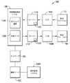
図1は、開示される実施形態の態様による保管および取出システムを概略的に示している。開示される実施形態の態様が、図面に関連して説明されるが、開示される実施形態の態様は、多くの代替形態で具現化され得ることが理解されるべきである。加えて、任意の適切なサイズ、形状または種類の、構成部分または材料が使用され得る。 FIG. 1 schematically illustrates a storage and retrieval system according to the disclosed embodiments. Although aspects of the disclosed embodiments are described in connection with the drawings, it should be understood that the aspects of the disclosed embodiments can be embodied in many alternative embodiments. In addition, components or materials of any suitable size, shape or type can be used.
開示される実施形態の態様による保管および取出システム100は、たとえば、小売店から受けた、ケースユニットの注文を履行するために、小売流通センタまたは倉庫において稼動してもよく、たとえばこれらは、2011年12月15日に出願された米国特許出願第13/326,674号明細書、および2010年4月12日に出願された、「Storage and Retrieval System」(WO Pub.2010/118412)と題されたPCT特許出願PCT/US10/30669号明細書に記載され、その開示内容の全ては、参照により本明細書に組み込まれる。 The storage and
保管および取出システム100は、インフィード移送ステーション170およびアウトフィード移送ステーション160、搬入鉛直方向リフト150Aおよび搬出鉛直方向リフト150B(典型的に、リフト150と呼ばれる)、保管構造130、ならびに、多数の自律型ローバーまたは自律型搬送車両110(ボットとも呼ばれる)を含んでいてもよい。保管構造130は、たとえば、複数レベルの保管ラックモジュールを含み、各レベルは、ケースユニットを保管構造130の任意の保管区域とリフト150の任意の棚との間で移送するために、それぞれの保管またはピッキング通路130Aおよび移送デッキ130Bを含んでいる。保管通路130A、および移送デッキ130Bはまた、ローバー110が、ケースユニットをピッキングストックの中に配置するために保管通路130Aおよび移送デッキ130Bを横断し、注文されたケースユニットを取り出すことを可能にするように構成される。 The storage and
ローバー110は、たとえば、保管および取出システム100の全体に亘ってケースユニットを運搬および移送することが可能な、任意の適切な自律型車両である。ローバー110は、上述の小売商品のようなケースユニットを保管構造130の1つまたは複数のレベル内のピッキングストックの中に配置し、そして、注文されたケースユニットを、たとえば店や他の適切な場所に出荷するために、注文されたケースユニットを選択的に取り出すように構成される。 The
ローバー110および保管および取出システム100の他の適切な機構は、たとえば、任意の適切なネットワーク180を通じて、たとえば、1つまたは複数の中央システム制御コンピュータ(たとえば、制御サーバ)120によって制御される。ある態様では、ネットワーク180は、任意の適切な種類および/または適切な数の通信プロトコルを用いた、有線ネットワーク、無線ネットワーク、または有線および無線ネットワークの組み合わせである。ある態様では、制御サーバ120は、ただ例示的な目的のために、稼働中の全てのシステム構成要素を制御、スケジューリング、モニタリングすること、在庫およびピッキングフェイス(pickface)を管理すること、および倉庫管理システム2500とインターフェイスで接続することを含む、保管および取出システム100の管理をするように構成された、実質的に同時に実行されるプログラムの集合を含む。 The
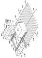
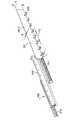
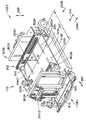
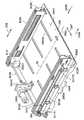
次に図2を参照すると、ローバー110は、第1端部110E1、および第1端部110E1から縦方向(longitudinally)に離間した第2端部110E2を有するフレーム110Fを含んでいる。フレーム110Fは、任意の適切な方法で積載ベッド200内部のピッキングフェイス210を支持するように構成された積載ベッド200を形成する。ある態様では、横方向(laterally)に配列されたローラ(示されず)がピッキングフェイスを支持し、ピッキングフェイス210が積載ベッドの内部で縦方向に移動することを可能にするが、他の態様では、積載ベッドは、積載ベッドの内部でピッキングフェイス210を支持するために、本明細書に説明されるもののような、1つまたは複数の、任意の適切な支持表面を有する。さらに別の態様では、エンドエフェクタ200Eが、積載ベッド200内でピッキングフェイス210を支持する。ローバー110は、保管および取出システム中におけるローバー110、エンドエフェクタ200E、およびローバーの任意の適切な移動可能な構成要素の移動を制御するために、ローバー110の1つまたは複数の駆動部に接続された、任意の適切な制御装置110C(図1)を含んでいる。本明細書において使用される「ピッキングフェイス」という用語は、たとえば、前後に、横並びに、またはその組み合わせで配置される、1つまたは複数の商品用ケースユニットである。開示される実施形態の態様を組み入れたローバー110の適切な例は、米国特許第8,425,173号明細書、および2014年3月17日に出願された、「Automated Storage and Retrieval System」と題された米国特許出願番号第14/215,310号明細書、2011年12月12日に出願された米国特許出願番号第13/236,423明細書(PG Pub.No.2012/0189409)、2011年12月15日に出願された米国特許出願番号第13/327,040明細書(PG Pub.No.2012/0197431)、2011年12月15日に出願された米国特許出願番号第13/326,952明細書(PG Pub.No.2012/0189416)、2011年12月15日に出願された米国特許出願番号第13/326,993明細書(PG Pub.No.2012/0185082)、2011年12月15日に出願された米国特許出願番号第13/326,447明細書(PG Pub.No.2012/0185122)、2011年12月15日に出願された米国特許出願番号第13/326,505明細書(PG Pub.No.2012/0195724)、に記載されたものであり、その開示内容の全ては、参照により本明細書に組み込まれる。 Next, referring to FIG. 2, the
さらに図2A、2B、および図3Aを参照すると、ローバー110は、積載ベッド200から、および積載ベッド200へピッキングフェイス210を移送するために、移動可能にフレーム110Fに接続された、任意の適切なエンドエフェクタ200Eを含んでいる。ある態様では、エンドエフェクタは、ピッキングフェイス210の対向する側面をまたいで伸長するように、および任意の適切な数のフィンガ250またはピッキングフェイス支持部材を用いて、各ピッキングフェイスの、たとえば底を(たとえば下から)上昇させ、支持することによってピッキングフェイス210を操作するように構成された、伸縮アーム220A、220Bを含んでいる。以下において説明されるように、ある態様では、フィンガ250はそれぞれのアーム220A、220Bに対して静止している(たとえば固定される)が、他の態様では(以下において説明されるように)、フィンガ250はそれぞれのアーム220A、220Bに対して作動される(たとえば移動可能である)。各アームは、保管棚の保管空間内に、エンドエフェクタ200Eの任意の適切な伸長または到達範囲を提供するために、任意の適切な数の伸縮部材を有する。たとえば、エンドエフェクタの各アーム220A、220Bの入れ子式の伸長および収縮のために、少なくとも伸縮部材300は、エンドエフェクタの伸長軸299に沿って別の伸縮部材301に摺動可能に連結される。各アームは、任意の適切な方法で、フレーム110Fに適切に取り付けられる。たとえば、ある態様では、レールまたはトラックなどの、任意の適切な数のガイド310が、任意の適切な方法でフレーム110Fに取り付けられる。各ガイド310がフレーム110Fに対して横方向に延在するように、レールは積載ベッド200の長手方向の各側面に取り付けられる、または近接している。ピッキングフェイス210を積載ベッド200から、および積載ベッド200へ移送するために、1つまたは複数の伸縮部材300、301が矢印299の方向で横方向に伸長するように、1つまたは複数の伸縮部材300、301は、ガイド310に摺動可能に取り付けられる。エンドエフェクタ200Eが、ローバー110の一方の側面のみから伸長されて図示されているが、他の態様では、エンドエフェクタ200Eは、ローバーのどちらの側面110S1、110S2(図6)からも伸長するように構成される。ある態様では、第1伸縮部材300は、たとえば、ガイド310上で適切なトラックに係合するガイドローラまたはスライダを用いるなどの任意の適切な方法で、ガイド310に摺動可能に取り付けられる。アーム220A、220Bの第1伸縮部材300は、ガイド310に関して上記のものと実質的に類似の方法で第2伸縮部材301を第1伸縮部材300に移動可能に取り付けるために、ガイド311を含む。図面には2つの伸縮部材が図示されているが、他の態様では、任意の適切な数の伸縮部材が、たとえば、伸長および収縮のために、上記のものと実質的に類似の方法で、互いに直列に取り付けられることが理解されるべきである。理解できるように、この場合第2伸縮部材301である、各アーム220A、220Bの直列に最も遠位に取り付けられた伸縮部材(たとえば、各アーム220A、220Bが伸長されると、各アーム220A、220Bの近位端部がフレーム110Fに最も近くなり、遠位端部がフレーム110Fから最も遠くなる)はフィンガ250を含むが、他の態様では、アームの任意の適切な伸縮部材がフィンガ250を含む。 Further referring to FIGS. 2A, 2B, and 3A, the
伸縮部材300、301のそれぞれは、伸縮部材300、301の少なくとも1つが、保管棚240上に配列された隣り合うピッキングフェイス210の間の空間SP(図2C)に伸長可能であるような、任意の適切な断面を有する。ある態様では、アーム220A、220Bの剛性を高めるために(たとえば、伸長時のアームの弛みを最小にし、より大きなアームの積載容量を可能にするために)、各伸縮部材300、301の高さHは伸縮部材の幅Wよりもかなり大きく、これにより、たとえば奥行きのある保管も容易となる(たとえば、1つまたは複数の商品用ケースユニットが前後に配置される場合)。アーム220A、220Bが、ピッキングフェイスの対向する側面をまたいで伸長するように、積載ベッド200の前部200Fおよび後部200Rに位置するため(前部および後部とは、例示目的のためにのみ本明細書で用いられ、他の態様では、積載ベッド200の長手方向における側面を参照するために、任意の適切な空間識別子が使用されてもよい)、二面でのピッキングも可能である。 Each of the
次に図3Aを参照すると、この態様では第2伸縮部材301である、各アーム220A、220Bの最も遠位の伸縮部材は、表面301Sを含み、フィンガ250が表面301Sから積載ベッド200の中心線に向かって延在している。理解できるように、各アームのフィンガ250は、ピッキングフェイスの下に延伸するために、互いに対向している。理解できるように、フィンガ250は、伸縮部材300、301の少なくとも1つ、およびフィンガ250が、ピッキングフェイス210間の空間SP(図2C)に延伸可能であるような、任意の適切な長さLを有する。この態様では、フィンガ250は、最も遠位の伸縮部材に対して固定されている(たとえば、フィンガは第2伸縮部材に対して移動不可能である)。しかし、他の態様では、図3Bおよび3Cに見られるように、たとえば、フィンガ250’、250’’は、最も遠位の伸縮部材301’に対して移動可能である。たとえば、ある態様では、フィンガ250’は、収縮位置と延伸位置との間で移動可能であるように、最も遠位の伸縮部材301’に回転可能に取り付けられる。収縮位置において、フィンガ250’は、たとえば、表面301Sと略平行であるが、延伸位置においては、フィンガ250’は、たとえば、1つまたは複数のピッキングフェイス210の下に延伸するため、表面301Sと略垂直である(または、表面301Sに対して、他の任意の適切な角度で配列される)。この態様では、フィンガ250’はそれぞれ、エンドエフェクタ200Eの伸長および収縮の方向299(図2A)と略垂直に延びる、それぞれの回転軸363の周りで回転可能である。別の態様では、フィンガ250’’は、たとえば、エンドエフェクタ200Eの伸長および収縮の方向299と略平行である、回転軸364の周りで回転可能である。たとえば、図3Bに見られるように、フィンガ250’’は、収縮位置と延伸位置との間で移動可能である。収縮位置において、フィンガ250’’は、表面301Sと略平行となるように、表面301S内に、または表面301Sに近接するように折り畳まれる。延伸位置において、フィンガ250’’は、1つまたは複数のピッキングフェイス210の下に延伸するために、表面301Sと略垂直に展開される。さらに他の態様では、フィンガは、収縮位置と延伸位置との間で移動するように、任意の適切な方法で、最も遠位の伸縮部材に対して移動可能である。 Next, referring to FIG. 3A, the most distal telescopic member of each
次に図2Cおよび図2Dを参照すると、フィンガ250が対向する配列では、たとえば、アーム220A、220Bが保管棚140内に伸長されるとき、フィンガは、保管棚140の支持表面140Sの間に位置する。たとえば、ある態様では、保管棚140は、エンドエフェクタ200Eの伸長および収縮の方向299と略垂直な(たとえば、交差する)方向297(図2A)に延在する、互いに離間した支持表面140Sを含んでいる。保管棚140に挿入されたときに、フィンガ250が、エンドエフェクタ200Eの伸長軸299を交差する方向に、棚構造物(たとえば、支持表面140S)に挟みこまれるように、たとえば、支持表面140S間のピッチP1(図2A)は、たとえば、フィンガ250間のピッチP2(図3A)に実質的に類似であるが、他の態様では、フィンガ間の間隔は、フィンガが支持表面の間の隙間を通過することを可能にする、任意の適切な間隔である。 Next, referring to FIGS. 2C and 2D, in an arrangement in which the
ふたたび図2Aを参照すると、ローバー110は、任意の適切な数の駆動装置を含む、駆動部260を有している。たとえば、駆動部260は、伸長/収縮の際にエンドエフェクタを軸299に沿って移動させるための、積載ベッドの中心線CL(図2Aおよび図5A参照)に向かってまたは離れるように、矢印297の方向にアームが共に、または別々に移動させられるように1つまたは複数のアーム220A、220Bを移動させるための、(たとえば、積載ベッド200および/または保管領域に対するピッキングフェイス210の位置調整のために)アーム220A、220Bが一体となって、積載ベッドの中心線CLに対して矢印297の方向に共に移動させられるようにアームを移動させるための、および、エンドエフェクタ200Eの伸長および収縮の軸(たとえば、方向299)と略垂直な方向298でアームを上昇/下降させるために構成された、1つまたは複数のエンドエフェクタ駆動装置260A、260B、260Cを含んでいる。ある態様では、少なくとも1つのピッキングフェイスのサイズと関わりなく、少なくとも1つのピッキングフェイスの全積載領域における位置調整(たとえば、アーム220A、220Bがアクセス可能である、積載ベッド内の任意の場所、および保管棚領域内の任意の場所における積載物の位置調整)をもたらすために、各移送アーム220A、220Bは、積載ベッド/積載領域のピッキングフェイス支持平面と略平行な平面において、横断する。図4も参照すると、ある態様では、(たとえば、アーム220A、220Bを矢印299の方向に移動させる)エンドエフェクタ伸長/収縮駆動部260Aは、ローバー110の各アーム220A、220Bを伸長および収縮させるために、任意の適切なベルト伝動部400を含んでいる。各伸縮部材300、301(図2Aおよび図3A参照)は、それぞれの伸縮部材300、301を連続して伸長させるように構成された(たとえば、伸長の第1段階において伸縮部材300、301が一体となって共に移動し、伸長の第2段階において伸縮部材300、301の一方のみが移動するように、伸長の第1段階において伸縮部材300、301の1つが、所定の距離/範囲を伸長し、そして伸長の第2段階において伸縮部材の他方が、所定の距離/範囲を伸長する)、任意の適切なベルトおよびプーリ装置400P1、400P2、400P3、400B1、400B2を含んでいる。他の態様では、ベルトおよびプーリ装置400P1、400P2、400P3、400B1、400B2は、たとえば、それぞれの伸縮部材300、301を実質的に同時に伸長させるように構成される(たとえば、伸縮部材300が積載ベッド200に対して移動し、伸縮部材301が伸縮部材300および積載ベッド200の両方に対して移動するように、伸縮部材300が所定の距離/範囲を伸長すると、伸縮部材301もまた対応する所定の距離/範囲を伸長する)。理解できるように、アーム220A、220Bの収縮は、上記のものの実質的に逆の方法で行われる。他の態様では、アーム220A、220Bを伸長および収縮させるために、たとえば、ボールおよびねじ装置、チェーン、油圧または空気圧アクチュエータ、伝動アクチュエータ、磁気駆動などのような任意の適切な駆動連結部が使用される。同様に、(たとえば、1つまたは複数のアームを297の方向に移動させる)アーム把持駆動装置260Bおよび(たとえば、アーム220A、220Bを矢印298の方向に移動させる)エンドエフェクタ上昇駆動装置260Cは任意の適切な構成を有し、上述の伝動部のような、アームを駆動するための任意の適切な伝動部を含む。理解できるように、ある態様では、アーム把持駆動装置260Bは、本明細書において説明されるように、1つまたは複数のアーム220A、220Bを移動させるために、1つまたは複数の駆動装置260B1、260B2を含んでいる。ある態様では、把持部駆動装置260Bは、アーム220A、220Bの一方をアーム220A、220Bの他方に対して移動させるために、アーム220A、220Bの1つまたは両方に連結された、単一駆動モータ260B1を含む(たとえば、以下において説明されるものと類似の方法で、共通の駆動モータによって、互いに向かって、または離れるように駆動するために、一方のアームの移動が他方のアームの移動に連結されるように、一方のアーム220A、220Bが移動する、または両方のアームが移動する間、アーム220A、220Bの他方は静止している)。他の態様では、把持駆動装置260Bは、少なくとも2つの駆動装置260B1、260B2を含み、各アーム220A、220Bは、他方のアーム220A、220Bから独立して移動するように、それぞれの駆動装置260B1、260B1によって駆動されている。理解できるように、たとえば保管空間または他のピッキングフェイス保持位置に対して、矢印297の方向にピッキングフェイス210の位置調整をもたらすために、各アームの独立移動は、ピッキングフェイス210の把持だけでなく、ピッキングフェイス210の矢印297の方向への移動も可能にする。さらに別の態様では、アーム220A、220Bは、任意の適切な数の駆動モータによって、任意の適切な方法で、矢印297の方向に移動可能である。 With reference to FIG. 2A again, the
上記のように、フィンガ250が棚140の支持表面140Sの下方に位置決めされるように、保管棚140は、たとえばアーム220A、220Bのフィンガ250が棚140を通過することを可能にするように構成される。ある態様では、保管棚140は、支持表面140Sが棚のワイヤで形成されるような、ワイヤ棚である。ワイヤ棚140は、ワイヤ棚の上部部材が支持表面140Sを形成し、ピッキングフェイスが棚140へ、および棚140から移送される方向299を実質的に交差する方向297に方向づけられた、および整列された、ワイヤメッシュ構成のような任意の適切な構成を有する。ワイヤ棚140は、任意の適切な方法で、保管ラック構造物(たとえば、水平支持部282など)および/またはピッキング通路デッキ/レールに留められる。ある態様では、ワイヤ棚140が、実質的に留め具または他の固定手段(たとえば、接着剤、溶接など)なしに、保管ラック構造物および/またはピッキング通路デッキ/レールに取り外し可能に固定されるように、ワイヤ棚140は、保管ラック構造物および/またはピッキング通路デッキ/レールに巻き付く。他の態様では、ワイヤ棚140は、取外し可能の留め具を用いて、保管ラック構造物および/またはピッキング通路デッキ/レールに取り外し可能に固定される。他の態様では、棚140は取外し可能でなくてもよい。 As described above, the
他の態様では、保管棚140’は、その開示内容の全てが参照により本明細書に組み込まれる、2010年4月9日に出願された米国特許出願第12/757,381号明細書に記載されたものと実質的に類似である。たとえば、図2Eを参照すると、各保管棚140’は、たとえば、保管棚140’の水平支持部282から延在する、1つまたは複数の支持脚部280L1、280L2を含んでいる。支持脚部280L1、820L2は、任意の適切な構成を有し、たとえば、チャネル部280Bによって脚部が互いに接続されるように、略U字型のチャネル280の一部であってもよい。チャネル部280Bは、チャネル280と1つまたは複数の水平支持部282との間に取付点を提供する。他の態様では、各支持脚部280L1、280L2は、水平支持部282に個別に取り付けられるように構成される。この態様では、各支持脚部280L1、280L2は、棚140’上に保管されたピッキングフェイスを支持するように構成された、適切な支持表面140S領域を有する、屈曲部280H1、280H2を含んでいる。屈曲部280H1、280H2は、たとえば、棚上に保管されたピッキングフェイスの変形を実質的に防止するように構成される。他の態様では、脚部280H1、280H2は、棚上に保管されたケースユニットを支持するために、適切な厚さを有する、または他の任意の適切な形状および/または構成を有する。図2Eに見られるように、支持脚部280L1、280L2またはチャネル280は、スラットを有するまたは波形の棚構造を形成してもよく、以下において説明されるように、たとえば支持脚部280L1、280L2の間の空間SP2は、エンドエフェクタ200Eのフィンガ250が、ピッキングフェイスを棚へ、および棚から移送するために、棚の中にまで届くことを可能にしている。 In another aspect, Storage Shelf 140'is described in US Patent Application No. 12 / 757,381, filed April 9, 2010, wherein all of its disclosures are incorporated herein by reference. It is substantially similar to what was done. For example, referring to FIG. 2E, each storage shelf 140'contains, for example, one or more support legs 280L1, 280L2 extending from the
理解できるように、ある態様では、本明細書に説明される保管棚は略平坦であり、保管および取出システム100の構造コストを低減させながら、保管および取出システム100の保管密度の増加を可能にしている。 As can be seen, in some embodiments, the storage shelves described herein are substantially flat, allowing an increase in the storage density of the storage and
上記のように、単一のピッキング通路デッキ130ADから複数の保管棚がアクセス可能であるように、(保管棚140、140’に実質的に類似の)保管棚140A、140B、140Cは、図7A〜7Cに示されているように上下に積み重ねられてもよい。ここでは、2つの保管棚140A、140Bが上下に積み重ねられ、単一のピッキング通路デッキ130ADからアクセス可能である。他の態様では、単一のピッキング通路デッキ130ADからアクセス可能である、3つ以上の保管棚が積み重ねられる。ある態様では、エンドエフェクタリフト駆動装置260Cは、エンドエフェクタの、保管および取出システムの複数の保管レベル間における走行を提供するように構成される。たとえば、図7A、7C、および7Cを参照すると、保管棚140により、移送デッキ130B(図1)のサイズの減少を可能にし、ピッキング通路デッキ130ADごとの複数レベルの保管部を提供することによってデッキ(たとえば、移送デッキ130Bおよびピッキング通路デッキ130ADの両方)の減少を可能にする、ピッキング通路130A(図1)の数の減少が可能になる。棚140の構成もまた、水平および鉛直方向のケース密度の増加を可能にする一方で、アーム220A、220Bを用いたケースユニットまたはピッキングフェイスの位置決め/位置揃えは、ピッキングフェイスを互いに近づくように移動させる(たとえば、上記のようにピッキングフェイスの間隔を減少させる)ことを可能にしてもよい。上記のように、ケースユニット間またはピッキングフェイス間の間隔は、1つまたは複数のケースユニットまたはピッキングフェイスを保管棚140へ、および保管棚140から移送するために、アーム220A、220Bが隣り合うケースユニットまたはピッキングフェイスの間に挿入されるための空間をもたらす。 As mentioned above,
さらに図7A〜7Cを参照すると、上記のように、ローバー110Aは、単一のピッキング通路デッキ130ADから積み重ねられた保管棚140A、140Bにアクセスするように構成されてもよい。この態様では、例示目的のみのため、各ピッキング通路デッキ130ADは、保管部の2つのレベル140A、140Bへのアクセスを提供しているが、他の態様では、各ピッキング通路は、保管部の3つ以上のレベルへアクセスを提供してもよい。各ピッキング通路からアクセスされる保管部のレベルはピッキング通路デッキごとに異なってもよい(たとえば、あるデッキは第1の数の保管レベルへのアクセスを提供してもよく、一方では、別のデッキは第2の数の保管レベルへのアクセスを提供してもよく、第2の数は第1の数とは異なっている)。上記のように、ローバー110は、本明細書で説明されるものに実質的に類似の方法でケースユニットまたはピッキングフェイスがピッキングまたは配置される保管レベルに応じた所定の高さに、アーム220A、220Bを上昇または下降させるエンドエフェクタリフト駆動装置260C(図2A)を含んでいてもよい。エンドエフェクタリフト駆動装置260Cは、たとえば、リニアアクチュエータ、スクリュードライブ、シザーリフト777(図7A)、磁気駆動部などの、アーム220A、220Bを持ち上げる、または下降させるように構成された任意の適切な駆動部である。 Further referring to FIGS. 7A-7C, as described above, the rover 110A may be configured to access the stacked
次に図2B、2Dおよび5A〜5Dを参照し、ピッキングフェイス210のピッキング動作が説明される。ローバー110は、たとえば、制御サーバ120(図1)のような、任意の適切な制御装置から、ピッキングフェイスを移送させるという命令を受ける。ローバーは移送デッキ130Bに沿って所定のピッキング通路130Aへ走行する。ローバー110はピッキング通路130Aに進入し、所定の保管位置で停止する(図5D、ブロック500)。上記のように、ローバー110は、ピッキングフェイス210の対向する側面210S1、210S2をまたいで伸長し、接合するように、および積載ベッド200へ、および積載ベッド200からピッキングフェイス210を移送するように構成されたアーム220A、220Bを有する、エンドエフェクタ200Eを含んでいる。理解できるように、アーム220A、220Bが積載ベッド200内に収縮され、ローバー110がピッキングフェイスを運搬していないとき、アーム220A、220Bは、ローバーが運搬可能であり、および/または保管および取出システム100に保管されている最も幅の広いピッキングフェイスの幅Wよりもかなり大きい距離D1だけ隔てられる。ローバー制御装置110Cは、たとえば、ピッキングフェイス210の幅W(図2B)に従ってアーム220A、220Bを保管位置に位置合せするために、アーム220A、220Bの1つまたは複数を長手方向に移動させるように、エンドエフェクタ駆動部260を動作させる。ある態様では、ローバー110は、ローバーが1つまたは複数のピッキング通路130A(図1)に沿って移動する時に、保管棚140上に位置する1つまたは複数のピッキングフェイスの側面210S1、210S2を検知するように構成された、(以下において説明されるような)任意の適切なセンサを含む。他の態様では、センサが、ピッキングフェイス(およびピッキングフェイスの側面)の位置を判定するために、保管棚の所定の特徴を検知し得るように、ピッキングフェイス210は、保管棚の所定の特徴に対して、保管棚140上に位置決めされる。ある態様では、ケースセンサは、その開示内容の全てが参照により本明細書に組み込まれる、2011年12月15日に出願された米国特許出願番号第13/327,035号明細書(PG Pub.2012/0189410)、および2012年9月10日に出願された、「Storage and Retrieval System Case Unit Detection」と題された、米国特許出願番号第13/608,877号明細書に記載されたものに実質的に類似である。伸長したときに、アーム220A、220Bが、積載ベッド200に移送されるピッキングフェイス210のどちらかの側面側の空間SP(図2C)内に位置決めされるように、ローバー110は、アーム220A、220Bの間の距離D1を調節するために、アーム220A、220Bの1つまたは複数を移動させる。ある態様では、ローバー110は矢印297の方向における位置調整を含み、ローバーの伸縮アームが、伸縮アーム220A、220Bをさらに1つまたは複数のピッキングフェイス210に位置合せするために(または保管位置にピッキングフェイスを配置する時にピッキングフェイスを保持位置に位置合せするために)、一体となって矢印297の方向に移動させられる、たとえば、ピッキングフェイス保持位置に対する、伸縮アームの高精度位置決めを含む(図5D、ブロック501A)。フィンガ250が1つまたは複数のピッキングフェイス210に実質的に位置合せされるように、およびフィンガが棚支持表面140S間の空間SP2内に位置決めされるように、ローバー110制御装置110C(図1)は、ピッキングフェイス保持位置の支持表面140Sと実質的に同等またはそれ以上のレベルにアーム220A、220Bを持ち上げ、保管棚140内に所定の距離、アーム220A、220Bを伸長させるように駆動装置260A、260Cに命令する(図5D、ブロック502)。ある態様では、アーム220A、220Bは、積載ベッド200の支持表面から独立して方向298に移動させられるが、他の態様では、その開示内容の全てが参照により既に本明細書に組み込まれた、米国特許仮出願第61/790,801号明細書に記載されたものに実質的に類似の方法で、積載ベッド支持表面が、ピッキングフェイスの移送先/移送元である支持表面140Sに近接するように、積載ベッドの支持表面もまた、(駆動装置260Cによって、または積載ベッドリフト駆動装置を用いて)方向298に移動するように構成される。ある態様では、任意の適切なセンサ257が、どの程度の深さまでアーム220A、220Bが保管位置内に伸縮されたかを判定するために、および(ピッキングフェイスの位置調整に関して、以下において説明されるように)ピッキングフェイスの(アーム220A、220Bの伸長方向に関する)前縁および後縁の境界線を判定するために、制御装置110Cにフィードバックを提供する。フィンガが、棚支持表面140Sの下方、所定の距離D2で位置決めされるように、駆動装置260Cを用いてアーム220A、220Bは下降される(図5D、ブロック503)。たとえば、伸縮部材301の表面301Sがピッキングフェイスを軽く把持し(たとえば、軽く把持するとは、ピッキングフェイスの位置合せのためにピッキングフェイスに触れることを意味し、ピッキングフェイスを保管棚から離して上昇させるためにピッキングフェイスを保持するための充分な把持力は触れることによって提供されない)、フィンガ250がピッキングフェイス210の下に位置するように、アーム220A、220Bの1つまたは複数は、駆動部260Bを用いてピッキングフェイス210の側面210S1、210S2に向かって、矢印297の方向に移動させられる(図5D、ブロック504)。他の態様では、表面301Sは、ピッキングフェイスを上昇させるための充分な把持力を提供してもよい。ピッキングフェイスの重量を支持するため、フィンガ250がピッキングフェイスの底部210B(図2A)と接触するように持ち上げられるように(たとえば、ピッキングフェイスが、フィンガ250とピッキングフェイスの底部との間の接触を可能にするように、表面301Sに沿って摺動してもよい)、駆動装置260Cを用いてアーム220A、220Bを上昇させることによって、ピッキングフェイス210が保管棚140から矢印298の方向に任意の適切な距離D3上昇されてもよい(図5D、ブロック505)。ピッキングフェイスが積載ベッド200の上方に配置されるように、アーム220A、220Bは矢印299の方向に収縮されてもよく(図5D、ブロック506)、ピッキングフェイス210が積載ベッド200内に矢印298の方向に下降されてもよい(図5D、ブロック507)。ある態様では、積載ベッド内に位置するとき、ピッキングフェイス210は、フィンガおよび/または任意の適切な積載ベッド200の支持表面によって支持される。理解できるように、ある態様では、ピッキングフェイスの位置調整のために、1つまたは複数のアーム220A、220Bが矢印297の方向に移動させられる、以下において説明されるもののような任意の適切な方法で、積載ベッド内でピッキングフェイスを位置調整する(たとえば、積載ベッドの1つまたは複数の基準面に対する所定の位置にピッキングフェイスを置く)ために、表面301Sが使用される(図5D、ブロック508)。 Next, the picking operation of the picking
ある態様では、ピッキングフェイス210の搬送の間、ピッキングフェイスは、アーム220A、220Bの表面301S、または他の任意の適切な、ローバーの位置合せ/把持表面によって、保持または挟持される。ピッキングフェイス210を任意の適切なピッキングフェイス保持位置に配置するために、ローバー110は、ピッキングフェイス保持位置に対する所定の場所に位置決めされてもよい。ある態様では、ピッキングフェイス210が位置調整される場合、ピッキングフェイス210をピッキングフェイス保持位置と位置合せするために、ピッキングフェイス210はアーム220A、220Bによって、積載ベッド200内で矢印297の方向に移動させられる。他の態様では、ローバー110の位置決めは、ピッキングフェイス210のピッキングフェイス保持位置との位置合せをもたらす。アーム220A、220Bは、ピッキングフェイスをピッキングフェイス保持位置の支持表面140Sと同等またはそれ以上のレベルに持ち上げ、アームは、上記のピッキングフェイスを積載ベッド200上に移送するためのものと実質的に反対の方法で、ピッキングフェイス210をピッキングフェイス保持位置の支持表面140S上に移送する。理解できるように、ローバー110へ、およびローバー110からの積載物の移送がピッキングフェイス210に関して説明されているが、上記の説明は、ローバー110へ、およびローバー110からの個別のケースユニットの移送にも適用されることが理解されるべきである。さらに、保管棚140、140’、140A、140Bについて言及されたが、ローバーは、ケースユニットおよび/またはケースユニットから形成されるピッキングフェイスを、保管棚140、140’、140A、140B、リフト150A、150Bの棚、などの任意の適切なピッキングフェイス保持位置、または他の任意の適切な場所に移送してもよいことが理解されるべきである。 In some embodiments, during transport of the picking
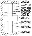
ふたたび図2B、2D、および5A〜5Dを参照して、ローバー110の例示的なピッキングフェイス構築動作が説明される。ローバー110は、上記のものと実質的に類似の方法で1つまたは複数の第1のピッキングフェイスを棚からローバー110に移送するために位置決めされる(図17、ブロック8000)。図2Cに図示されているように、アーム220A、220Bを、(隣り合うケースユニット/ピッキングフェイス間の空間SPに合うように)1つまたは複数の第1のピッキングフェイス210と位置合せするために、アーム220A、220B間の間隔D1は、矢印297の方向に調節される(図17、ブロック8001)。上記のように、ある態様では、ローバー110は矢印297の方向における位置調整を含み、ローバーの伸縮アームが、伸縮アーム220A、220Bをさらに1つまたは複数のピッキングフェイス210に位置合せするために、一体となって矢印297の方向に移動させられる、たとえば、ピッキングフェイス保持位置に対する、伸縮アームの高精度位置決め、を含む(図17、ブロック8001A)。伸縮アーム220A、220Bは、図5Dのブロック502〜508に関する上記の方法で、1つまたは複数の第1のピッキングフェイス210を積載ベイに移送する(図17、ブロック8003)ために、矢印299A、299Bの方向に伸長および収縮する。1つまたは複数の第1のピッキングフェイス210が積載ベッド200内に位置決めされると、1つまたは複数の第2のピッキングフェイス210X(図2C)の積載ベイ200への移送のために、ローバー110はピッキング構造物を横断し、別のピッキングフェイス保持位置に対して位置決めされる(図17、ブロック8000)。他のピッキングフェイス保持位置において伸縮アーム220A、220Bを1つまたは複数の第2のピッキングフェイス210Xに位置合せするために、積載ベイ内の1つまたは複数のピッキングフェイス210は非挟持とされ、伸縮アーム220A、220Bの間の間隔は調節され(図17、ブロック8001)、および/または位置調整される(図17、ブロック8001A)。理解できるように、積載ベッド200上ですでに保持されている1つまたは複数の第1のピッキングフェイスは、伸縮アームが位置調整される時に、伸縮アーム220A、220Bを用いて矢印297の方向に移動させられる。図5Dのブロック502〜508に関する上記の方法で、1つまたは複数の第2のピッキングフェイス210Xを積載ベイに移送するために、伸縮アーム220A、220Bは、矢印299A、299Bの方向に伸長および収縮される(図17、ブロック8003)。理解できるように、1つまたは複数の第2のピッキングフェイスの積載ベイ200内への移送の間、フィンガ250が積載ベイ200内の1つまたは複数の第1のピッキングフェイスに接触しないように(および/または図3Bおよび3Cを参照すると、1つまたは複数のフィンガ250’、250’’は、積載ベイ200内でピッキングフェイス210と接触しないように、位置決めされる、たとえば、収縮される)、伸縮アーム220A、220Bは、1つまたは複数の第1のピッキングフェイス210の側面から離間していてもよい。他の態様では、1つまたは複数の第2のピッキングフェイス210Xのピッキングの間、アーム220A、220Bが保持位置に伸長される時に、接触せずに1つまたは複数の第2のピッキングフェイス210Xをまたいで伸長するように、アーム220Aと220Bが離間することを可能にしながらも、1つまたは複数の第1のピッキングフェイス210がアーム220A、220Bによって保持されるように、アーム220A、220Bの自由端から最も遠位のフィンガ250(図2D)は、自由端FEに近接するフィンガ250よりも長い。ピッキングフェイス210、210Xの積載ベッド200への移送に関する上記のものと実質的に反対の方法で、1つまたは複数の第1および第2のピッキングフェイス210、210Xは、ローバー110によって一体となって移送され、ピッキングフェイス保持位置に一体となって(または、個々に、1つまたは複数のピッキングフェイス保持位置に)配置される。 Again, with reference to FIGS. 2B, 2D, and 5A-5D, an exemplary picking face construction operation of the
ある態様では、上記のように、ローバー110は、その開示内容の全てが参照により既に本明細書に組み込まれた、2014年3月17日に出願された、「Automated Storage and Retrieval System」と題された米国特許仮出願番号第14/215,310号明細書に記載されたもののような位置調整機能を含んでいる。たとえば、ある態様では、ローバー110は、(上記のように、一方のアーム220A、220Bが固定され、他方のアーム220A、220Bが方向297で移動可能である、または両方のアーム220A、220Bが方向297で移動可能である)能動型側面位置調整を含む。ケースの境界を物理的に確認するための、任意の適切なセンサ257(図2A)もまた、積載ベッド200の近傍または内部に、および/または1つまたは複数のアーム220A、220B上に位置してもよい。ある態様では、センサ257は、ローバーのアーム220A、220B上に設置されたビームライン式またはカーテン式センサである。センサ257によって、ローバーが、ピッキングフェイスを配置する時に、たとえば、ピッキングフェイスのための保管棚140、140’、140A、140Bなどの、任意の適切なピッキングフェイス保持位置に、充分な、空いている空間が存在することを確認すること、およびピッキングフェイスが正確な後退(たとえば、ピッキングフェイス保持位置ピッキング通路エッジから、または他の任意の適切な基準面からピッキングフェイスが位置する距離)を有して配置されることを確認することが可能になる。保持位置からピッキングフェイス210をピッキングする際、センサ257は、ケースの標的化、およびアーム220A、220Bが保管位置内に伸長される深さの確認を可能にする。ある態様では、アーム220A、220Bは、保管位置の深い場所に(たとえば、保管棚140のエッジから遠い保管位置に)配置されるピッキングフェイスのための案内も行う。 In some embodiments, as described above, the
ピッキングフェイスの位置調整が提供される場合、ある態様では、ローバー110の積載ベッド200は、ピッキングフェイス210(およびピッキングフェイスを形成するケースユニット)の、積載ベッド200の表面に沿った、多自由度の摺動移動を可能にするように構成される。ある態様では、積載ベッドは、低摩擦係数を有する任意の適切な材料で構成された、略平坦な表面であるが、他の態様では、積載ベッドは、上にピッキングフェイスが乗る複数のボールベアリングを含み、さらに他の態様では、積載ベッド200は、上記のもののような、ピッキングフェイス210(およびピッキングフェイスを形成するケースユニット)の、積載ベッド200の表面に沿った多自由度の摺動移動を可能にする、任意の適切な構成を有する。他の態様では、ピッキングフェイスは、フィンガ250によって積載ベッド表面の上方に保持されている間に位置調整される。 When picking face alignment is provided, in some embodiments, the
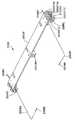
図6を参照すると、上記のように、ある態様では、ローバー110は、保管棚140上に位置する1つまたは複数のピッキングフェイス210の位置を検知するための、任意の適切なセンサを含んでいる。開示される実施形態のある態様では、保管棚140の水平支持部282上に、または水平支持部282内に設置された所定の特徴または標的611、612、613(たとえば、溝、突出部など)を感知するために、ローバーは、積載ベッド200の下でローバー110のフレーム110F上に位置決めされてもよい、1つまたは複数のビーム式センサ600、601および/または近接センサ602、603を含む。たとえば、米国特許仮出願番号61/790,801号明細書に記載されたものと実質的に類似の方法でローバーの位置を判定するために、各標的611、612、613がそれぞれのセンサ600、601、602、603によって感知されると、そのセンサがオン/オフの信号を提供するように、たとえば、センサ600、601、602、603は、たとえば水平支持部282上の標的611、612、613を感知するために、位置決めされる。理解できるように、標的611、612、613がピッキング通路130Aの水平支持部282上、しかし一方の水平支持部上に位置する場合、センサ600、601、602、603が、ローバーの走行方向にかかわらず標的611、612、613を感知するように、ローバーは、ローバーの横方向の両側面110S1、110S2上に、センサ700、701を有する。理解できるように、センサが、標的ではなく、保管棚140上に位置するピッキングフェイス210を検知するためのものである場合、センサはピッキングフェイス210を検知するために、任意の適切な高さでローバー上に位置する。ある態様では、ビームセンサ600、601および1つまたは複数の近接センサ602、603が、保管構造物内でのローバーの位置を判定するために、互いに併せて使用される。ある態様では、ピッキング通路130A内でのローバーの場所を判定するために、近接センサ602、603が使用されるが、ローバー110と保管棚140との間でピッキングフェイス210を移送させるために、ローバー110のアーム220A、220Bをピッキングフェイス210間の空間SPと位置合せするため、標的611、612、613の間の領域でのローバーの場所を判定するためにビームセンサ600、601が使用され、他の態様では、保管構造物内でのローバーの場所を判定するために、およびローバー110と保管棚140との間でピッキングフェイスを移送するために、ビームセンサ600、601および近接センサ602、603が任意の適切な方法で使用される。 Referring to FIG. 6, as described above, in some embodiments, the
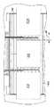
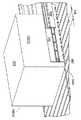
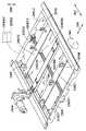
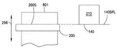
次に図8を参照すると、開示される実施形態の態様に従って、ローバー110が図示される。ローバー110は、指摘される所を除いて上記のものと実質的に類似である。ここで、ローバー110は、第1端部110E1および第1端部から長手方向に離間した第2端部110E2を有するフレーム110Fを含んでいる。フレーム110Fは、カーテシアン型伸縮マニピュレータ800Eが取り付けられた積載領域200Aを形成する。以下において説明されるように、マニピュレータ800Eは、たとえば、任意の適切な保管棚とローバー110の積載ベイとの間で、ピッキングフェイス210を押すまたは引くことによって、様々な長さおよび幅のピッキングフェイス210(図2A)を操作するように構成される。ある態様では、保管棚は、上記の保管棚140(図2A)に実質的に類似であってもよいが、他の態様では、保管棚は、ワイヤラックピッキングフェイス支持表面ではなく、略平坦なピッキングフェイス支持表面、またはスラットを有するピッキングフェイス支持表面を含んでもよい。 Next, with reference to FIG. 8, the
この態様では、マニピュレータ800Eは、(以下において説明されるような)少なくとも3自由度の駆動装置を有する駆動部、1つまたは複数の伸縮アーム802A、802B(たとえば、典型的にはエンドエフェクタ802)、積載ベイ200、および少なくとも1つのマスト組立体またはマスト部材801A、801Bを含む。ある態様では、積載ベイ200は、フレーム110Fの積載領域200Aに取り付けられた、2つのマスト組立体またはマスト部材801A、801B間で吊設されるが、他の態様では、積載ベイ200は、(マスト部材801A、801Bの1つなどの)単一のマスト部材から片持ちされてもよい。以下においてより詳細に説明されるように、マスト部材801A、801Bは、積載ベイ200の矢印298の方向(たとえば、ローバーが走行する表面に対して垂直)における移動をもたらすために、ガイドを含む。積載ベイ200と棚140との間でピッキングフェイス210を移送するため、エンドエフェクタ802が、積載ベイ200の外まで届く/伸長するように、矢印299の方向に伸長および収縮するために、積載ベイ200内に少なくとも部分的に取り付けられる。ここで、エンドエフェクタ802は、実質的に積載ベイ200の(たとえば、矢印297の方向において)両側に設置された2つの伸縮アーム802A、802Bを含む。伸縮アーム802A、802Bは、積載ベイ内において矢印297の方向で、互いに向かって、または互いから離れるように移動可能であるように、積載ベイ200内に少なくとも部分的に取り付けられる。理解できるように、積載ベイ200は、積載ベッド200内で略平坦な表面またはプレート200Sなどの任意の適切な方法で、ピッキングフェイス210を支持するように構成される。 In this aspect, the
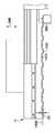
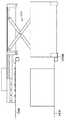
次に図9を参照すると、ある態様では、マスト部材801A、801B(一般的にマスト部材801と呼ばれる)は、実質的に同じ構成を有するが、他の態様では、マスト部材801A、801Bは、それぞれ任意の適切な構成を有する。ここで、各マスト部材801は、フレーム801F、キャリッジ803、および駆動装置810(たとえば鉛直駆動装置)を含んでいる。フレーム801Fは、フレーム801Fの両鉛直面に設置された、2つの対向するチャネル801Cを形成する。キャリッジ803は、矢印298の方向に鉛直移動するために、チャネル801Cの間に延在する、およびチャネル801C内に取り付けられる。たとえば、図10も参照すると、キャリッジ803は、キャリッジ803の両端部803E1、803E2に取り付けられたガイドホイール部材またはガイドホイールアセンブリ803Gを含んでいる。各ガイドホイール部材は、それぞれのチャネル801Cの1つまたは複数の側面に係合する、1つまたは複数のガイドホイール803R1A、803R1B、803R2を含んでいる。たとえば、各ガイド部材803Gは、1つまたは複数の方向297、299においてキャリッジを安定させる、ガイドホイール803R1A、803R1B、803R2を含む。ここでは、図9Aにも見られるように、各ガイド部材803Gは、矢印297の方向においてキャリッジ803の移動を安定させるために、共通のチャネル801Cの両側面801CS1、803CS2に係合する(たとえば、ホイール803R1Aが側面803CS2に係合し、ホイール803R1Bが側面803CS1に係合する、またはその逆である)、1つまたは複数のガイドホイール803R1A、803R1B、および矢印299の方向においてキャリッジ803の移動を安定させるために、(両側面に亘って及ぶ)チャネル801Cの反対側の側面に係合する1つまたは複数のガイドホイール803R2を含んでいる。理解できるように、チャネル801C内において、矢印299の方向に延在する軸の周りのキャリッジの捩れ動作TM1を実質的に排除するために、(たとえば、矢印298の鉛直方向において)最上部の(端部803E2の)ホイール803R1A、(端部803E1の)803R1Bがそれぞれのチャネルの両側面に係合し、最下部の(端部803E2の)ホイール803R1B、(端部803E1の)803R1Aがそれぞれのチャネルの両側面に係合するように、ガイドホイール部材803Gは、互いに対する鏡像である。矢印297の方向に延在する軸の周りの、キャリッジ803の捩れ動作TM2は、ワイヤロープリービングにより実質的に排除され、ワイヤロープリービングは、ワイヤ803W1、803W2およびプーリ803P1、803P2を含み、プーリ803Pa、803P2がキャリッジ803に取り付けられ、ワイヤ803W1、803W2の端部803WEが、たとえば、それぞれのマスト部材801に定着されている。図10に見られるように、ワイヤロープリービングは、ワイヤロープ802W1、803W2が、反対側の側面および/またはフレーム803Fの端部でリービングと交差し、抜け出るようにプーリを通過するように、配列される。たとえば、ワイヤロープ803W1は、端部803E2においてフレームに入り、プーリ803P1に係合し、フレームの長さに沿って進行し、プーリ803P2に係合し、そして反対側の端部803E1において反対側からフレームを抜け出る。同様に、ワイヤロープ803W2は、端部803E1においてフレームに入り、プーリ803P2に係合し、ワイヤロープ803W1と交差しながらフレームの長さに沿って進行し、プーリ803P1に係合し、そして反対側の端部803E2において反対側からフレームを抜け出る。この交差リービング配列は、キャリッジを、マスト801に沿った走行のために、所定の方向付け(たとえば、水平方向)に限定する。 Next, referring to FIG. 9, in one embodiment, the
キャリッジ803は矢印298の方向に、ベルトおよびプーリ駆動システムを含む駆動装置810(たとえば、鉛直駆動装置)によって、などの任意の適切な方法で駆動されるが、他の態様では、リードスクリュー駆動部または他のリニアアクチュエータがキャリッジを矢印298の方向に駆動する。駆動装置810は、マスト801に取り付けられたフレーム810Fを含んでいる。駆動モータ260Cは、駆動装置260Cの出力軸に取り付けられたプーリ810P2を用いてベルト810Bを駆動するために、フレーム810Fに取り付けられる。ベルト810Bは、フレーム810Fに取り付けられた、1つまたは複数のプーリ801P1、801P3、801P2に巻きつけられ、ガイドされる。ベルト810Bが移動すると、キャリッジ803がベルト810Bとともに矢印298の方向に移動するように、ベルト810Bは、キャリッジの取付け台803Bを介してキャリッジ803に固定される。理解できるように、各マスト部材801A、801Bはそれぞれの鉛直駆動装置を含み、マスト部材801A、801Bの間に吊設された積載ベイ200のレベルが維持されるように、駆動装置810は制御装置110C(図1)のような、マスタ−スレーブ制御システムによって駆動される。たとえば、少なくともマスト部材801によって区切られた走行の範囲内の、積載ベイ200の鉛直方向の位置決めは無制限である。理解できるように、チャネル801Cの高さおよび/またはフレーム801Fの幅(たとえば、両側のチャネル801Cの間の距離)は、積載ベイ200の走行時の高さHおよび/または深さDに応じて適切にサイズ決めされる。図9に見られるように、1つまたは複数のキャリッジ803が積載ベイ200を支持する、あるいは運搬するように(たとえば、積載ベイが1つまたは複数のキャリッジ803から吊り下げられる)、キャリッジ803および積載ベイ200が互いに連結され得るように、各マスト部材801はチャネル801Aを含んでいる。 The
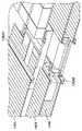
次に図8および11を参照すると、積載ベイ200は、フレーム200Fおよびフレーム200Fに取り付けられたピッキングフェイス支持表面200S(図11に示されず)を含んでいる。フレーム200Fは、2つのエフェクタキャリッジ200G1、200G2が、矢印297の方向に走行するように取り付けられた、対向するチャネル200C1、200C2を画定する。図12Aおよび12Bも参照すると、各エフェクタキャリッジ(全体的にはエフェクタキャリッジ200G)は、両側端部200GE1、200GE2に設置されたガイドホイールキャリッジ200RCを有するフレーム200GFを含んでいる。各ガイドホイールキャリッジ200RCは、矢印298、299の方向における移動からエフェクタキャリッジ200Gの移動を安定させるために、チャネル200Cの1つまたは複数の壁に係合するように構成された、1つまたは複数のガイドホイール200GP1A〜200GP1Dを含んでいる。たとえば、図11Aを参照すると、各ガイドホイールキャリッジ200RCは、矢印298の方向におけるエフェクタキャリッジ200Gの移動を安定させるために(および方向299と略平行である軸の周りの、エフェクタキャリッジ200Gの捩じり動作TM3を実質的に排除するために)それぞれのチャネル200Cの対向する側面200CS1、200CS2に係合する1つまたは複数のガイドホイール、および矢印299方向におけるエフェクタキャリッジ200Gの移動を安定させるために、それぞれのチャネル200Cの他の壁200CS3に係合する1つまたは複数のガイドホイールを含んでいる。矢印298の方向と略平行である軸の周りの、エフェクタキャリッジ200Gの捩れ動作TM4は、キャリッジ803に関する上記のものと実質的に類似の方法で、(上記のものと実質的に類似の)ワイヤロープリービングによって、実質的に排除され、ワイヤロープリービングはワイヤ200W1、200W2およびフレーム200GFに取り付けられたプーリ200P1〜200P4を含み、ワイヤ200W1、200W2の端部200WEがたとえば、積載ベッドのフレーム200F、またはローバー110の他の任意の適切な部分に留められる、あるいは固定される。各エフェクタキャリッジは、それぞれのエフェクタキャリッジ200Gを駆動ベルト260DBに固定するための、駆動ベルト連結部材200GBAも含んでいる。フレーム260Fに取り付けられたモータ260Dは、エフェクタキャリッジ200G1、200G2を互いに向けて、および互いから離れるように移動させるために、(プーリ260DP1、260DP2とともにフレーム200Fに取り付けられた)駆動ベルト260DBを駆動させ、一方のエフェクタキャリッジ200G1は、(プーリ260DP1、260DP2の周りで輪になる)駆動ベルト260DBの上部260DBTに取り付けられており、他方のエフェクタキャリッジ200G2は、駆動ベルト260DPループの底部260DBBに取り付けられている。エフェクタキャリッジ200G1、200G2の位置はそれらの走行の範囲の間において無制限である。積載ベイ200の長さおよび幅は、任意の適切な長さおよび幅を有するピッキングフェイスを支持するようにサイズ決めされてもよく、エフェクタキャリッジ200G1、200G2は様々なサイズのピッキングフェイスを収容するように調節される。理解できるように、伸縮アーム802A、802Bがキャリッジ200G1、200G2のそれぞれ1つに取り付けられるように、1つまたは複数のアーム取付け台200Mが各エフェクタキャリッジ200G1、200G2に固定される。アーム取付け台200Mは、ピッキングフェイス支持表面200Sに形成された溝または開口200SA内を進行するように、積載ベイ200のピッキングフェイス支持表面200Sを通過して延在する。他の態様では、1つまたは複数のピッキングフェイスがフレーム110Fおよび/またはピッキングフェイス保持位置に対し、矢印297の方向に位置調整されるように、各エフェクタキャリッジ200G1、200G2は、上記のものに類似の方法で、他のエフェクタキャリッジから独立して移動可能である。たとえば、この態様では、エフェクタキャリッジ200G1、200G2の一方は、モータ260Dによる矢印297の方向における移動のために、駆動ベルト260DBに連結される。他方のエフェクタキャリッジ200G1、200G2は、(モータ260Dに実質的に類似である)第2のモータ260D2による矢印297の方向における移動のために、(上記のものに実質的に類似の方法で)第2の駆動ベルト260DB2に連結される。ここで、1つまたは複数の伸縮アーム802A、802Bを移動させることによってピッキングフェイスが矢印297の方向に位置調整され得るように、各エフェクタキャリッジ、および、したがって各伸縮アーム802A、802Bは、独立して移動可能であり、および共に移動可能である。 Next, referring to FIGS. 8 and 11, the
次に図13、14Aおよび14Bを参照すると、伸縮アーム802A、802Bのそれぞれは、3つのリンク802FL、802CL、802ILを含んでいるが、他の態様では、各伸縮アーム802A、802Bは3つ以上または1つのリンク、のような任意の適切な数のリンクを含む。ここでは、各伸縮アームは、アーム取付台200Mに取り付けられた固定リンク802FL、中央リンク802CL、および内側リンク802ILを含んでいる。中央リンク802CLは、固定リンク802FLに対し、矢印299の方向に移動可能となるように、任意の適切な直線スライド802CRまたは他の直線移動可能な結合部によって、固定リンク802FLに取り付けられている。内側リンク802ILは、中央リンク802CLに対し、矢印299の方向に移動可能となるように、任意の適切な直線スライド802IRまたは他の直線移動可能な結合部によって、中央リンク802CLに取り付けられている。駆動ベルト501Bはプーリ501P1、501P2によって固定リンク802FL上に取り付けられ、プーリ501P1は駆動連結部501を有する従動プーリである。駆動モータ260Aは、フレーム200Fに取り付けられ、たとえば、ベルトおよびプーリ伝動部、ギヤ駆動伝動部、チェーン駆動伝動部、または他の任意の適切な駆動連結部などの任意の適切な伝動部260ATによって1つまたは複数の駆動軸500A、500Bに動作可能に連結される(図面には2つの駆動軸が示されているが、他の態様では、3つ以上または1つの駆動軸が使用される)。1つまたは複数の駆動軸500A、500Bは、プーリ501P1を、そしてベルト501Bを駆動するために、モータを駆動連結部501に接続させる。ベルト501Bが移動すると、中央リンク802CLがベルト501Bにより矢印299の方向に移動するように、中央リンク8012CLは、連結部501Cによりベルト501Bに連結される。別の駆動ベルト501B2が、ベルト501Bに関する上記のものと類似の方法で、プーリとともに中央リンク802CL上に取り付けられる。中央リンク802CLが矢印299の方向に駆動されると、ベルト501B2の従動する性質によって内側リンク802ILと中央リンク802CLとの間の相対移動が引き起こされ、それによって、内側リンク802ILも矢印299の方向に移動し、リンク802FL、802CL、802ILが入れ子式に伸長するように、ベルト501B2は固定リンク802FLおよび内側リンク802ILの両方に固定される。 Next, referring to FIGS. 13, 14A and 14B, each of the
ある態様では、ピッキングフェイス係合または押出部材900Tが、矢印299の方向に移動可能となるように、内側リンク802ILに取り付けられる。別のピッキングフェイス係合またはフィンガ部材900Fが、矢印299の方向と略平行である軸FAXの周りで回転可能となるように、展開位置(図14B参照)と収縮位置(図14A参照)との間で回転されるように、内側リンク802IL上に取り付けられる。押出部材900Tは、内側リンク802ILの開口900TA内で矢印299の方向に往復移動するように、リニアドライブまたはリニアアクチュエータ900TMによって駆動される。押出部材900Tは、矢印299Aの方向に移動させられたとき、ピッキングフェイスを所定の棚140上に押し出すために、矢印297の方向で積載ベイ200の中心線PBCLに向かって延在するピッキングフェイス係合表面900TSを含む。ある態様では、押出部材900Tは、ピッキングフェイス保持位置に配置されたとき、たとえば、ピッキングフェイスのサイズ、保管ラック構造物(たとえば、ピッキングフェイス保管位置)および伸縮アーム802A、802Bの伸長/収縮のうちの、1つまたは複数とは関わりなく、矢印299の方向において、1つまたは複数のピッキングフェイスの位置調整をもたらす。言い換えると、矢印299の方向における押出部材の移動は、保管ラック(ピッキングフェイス保管位置)を横切る伸長および収縮の方向に沿った、および伸縮アーム802A、802Bの伸長/収縮とは関わりなく、独立的に可変のピッキングフェイスの位置調整をもたらす。理解できるように、ある態様では、少なくとも1つのピッキングフェイスのサイズとは関わりなく、少なくとも1つのピッキングフェイスの全積載領域における位置調整(たとえば、上記のような、積載ベッド内の任意の場所およびアーム220A、220Bがアクセス可能である保管棚領域内の任意の場所における積載物の位置調整)をもたらすために、矢印299、297の1つまたは複数の方向におけるアーム802A、802Bに加えて、矢印299方向における1つまたは複数の押出部材900Tは、積載ベッド/積載領域のピッキングフェイス支持平面と略平行である平面において移動する。 In some embodiments, the picking face engagement or
フィンガ部材900Fは、回転モータ900FMのような任意の適切な駆動装置によって、内側リンク80IL上に回転可能に取り付けられる。また、図13Aを参照すると、たとえば、各伸縮アームが、棚140上に位置するピッキングフェイスに干渉せずに、ピッキングされるピッキングフェイスをまたいで伸長するために、隣り合うピッキングフェイスの間に伸長されるように、ピッキングフェイス210が棚140上に押し出されるとき、またはエンドエフェクタ802が棚140上のピッキングフェイス保管位置内に伸長している間、ピッキングフェイス210が自由端を超えて進行することが可能になるように、フィンガ部材900Fは収縮位置に設置される。フィンガ部材900Fは、伸縮アーム802A、802Bが棚の外に向かって移動し、ピッキングフェイスを積載ベイ200内に搬送する時に棚140からピッキングフェイスを引き出すために所定のピッキングフェイスに係合する、ピッキングフェイス係合表面900FSを含む。図13、14A、14Bに見られるように、フィンガ部材900Fは内側リンク802ILの自由端FEに位置し、軸FAXの周りで回転する。作動中、ピッキングフェイス210をピッキングするために伸縮アーム802A、802B(たとえばエンドエフェクタ802)が棚140内に伸長されるとき、ピッキングフェイス係合表面900FSがピッキングフェイスの後ろに設置されるように、フィンガ部材900Fはピッキングフェイス210の端部210Eを超えて位置決めされ、そして展開位置へと回転される。エンドエフェクタ802が矢印299Bの方向に収縮されると、フィンガ900Fのピッキングフェイス係合表面900FSはピッキングフェイス210に係合し、積載ベイ200内にピッキングフェイス210を引き込む。 The
理解できるように、押出部材900Tは、矢印299の方向に、フィンガ部材900Fに向かって、またはフィンガ部材900Fから離れるように移動可能である。フィンガ部材900Fに対する、この押出部材900Tの往復移動は、フィンガ部材900Fと押出部材900Tとの間での、ピッキングフェイス(たとえば異なる深さ/サイズDPを有するピッキングフェイス)の把持(たとえば捕捉)および解除をもたらす。たとえば、エンドエフェクタ802の伸長の長さに応じた、無制限の数の所定の位置においてピッキングフェイスが棚上に押し出されるように、押出部材900Tとフィンガ部材900Fとの間の相対移動もまた、伸縮アーム802A、802B(たとえばエンドエフェクタ802)の自由端FEにおけるピッキングフェイスの位置調整をもたらす。 As can be seen, the
ある態様では、1つまたは複数のアーム802A、802Bは、アーム802A、802Bのそれぞれの1つまたは両方の押出部材用モータ900TMおよびフィンガ用モータ900FMを制御するための無線制御モジュール910を含む。理解できるように、ある態様では、各伸縮アーム802A、802Bは、それぞれのモータ900TM、900FMを制御するためのそれぞれの無線制御モジュール910を含むが、他の態様では、共通の無線制御モジュール910が伸縮アーム802A、802B上の両方のモータ900TM、900FMを制御してもよい。1つまたは複数の無線制御モジュール910はそれぞれの伸縮アーム802A、802Bの内側リンク802ILに取り付けられるが、他の態様では、無線制御モジュール910はそれぞれの伸縮アーム802A、802Bの任意の適切な場所に取り付けられる。無線制御モジュール910は、たとえばブルートゥース(登録商標)、赤外線、無線周波数、または他の任意の形態の無線通信などの任意の適切な方法で、たとえば、ローバー制御装置110C(図1)との無線通信のために構成される。無線制御モジュール910は、モータ900TM、900FMに動力を供給するバッテリ910B、およびバッテリ910Bを充電するための接触部910Cを含む。たとえば、伸縮アーム802A、802Bがホームまたは完全に収縮された構成/位置にあるとき、図8および13に図示されているように、バッテリが再充電されるように、接触部910Cは積載ベイ200の接触部200CTに係合する。ここでは、接触部は機械的接触部として図示されているが、他の態様では、バッテリ910Bの再充電は、電磁誘導のような非接触型充電によって実施されてもよい。理解できるように、押出部材用モータ900TMおよびフィンガ用モータ900FMの無線制御は、たとえば、空間を大きく占有し、信頼性にかかわる問題となり得る、積載ベイ200と伸縮アーム802A、802Bの各リンクとの間の屈曲式ワイヤを実質的になくす。 In some embodiments, one or
ある態様では、図13に最も良く図示されているように、モータ260Aのような単一のモータが伸縮アームの両方を駆動する。上記のように、モータ260Aは、たとえば、積載ベイ200の中央後部において、積載ベイ200のフレーム200Fに取り付けられるが、他の態様では、モータ260Aは、積載ベイ200に対して任意の適切な場所に取り付けられてもよい。モータ260Aは、ベルトおよびプーリ伝動部260AT、チェーン駆動伝動部、ギヤ駆動伝動部、または他の任意の伝動部などの任意の適切な伝動部に連結される。伝動部260ATは、モータ260Aの出力軸を、たとえば伝動部260ATからどちらかの方向に伸長するように、たとえば伸縮アーム802A、802Bと略垂直に方向付けされた駆動軸500A、500Bに連結する。2つの駆動軸500A、500Bが図示されているが、他の態様では、単一の駆動装置が使用される。駆動軸500A、500Bは、たとえば、スプライン継手、六角継手、フランジ継手、ビームカップリング、リジッドカップリング、または以下において説明されるような、駆動軸500A、500Bを伝動部260ATおよびプーリ501P1に連結するための他の任意の継手などの、任意の適切な駆動係合部または連結部を含む、任意の適切なシャフトであってもよい。たとえば、上記のように、プーリ501P1は、駆動軸500A、500Bのそれぞれの1つの駆動連結部とかみ合う駆動連結部501を含んでいる。ある態様では、たとえば非整列による結着を避けるために、駆動軸500A、500Bが固定アームリンク802FLに設置されたプーリ501PSの駆動連結部501によって支持されるように、駆動軸500A、500Bとプーリ501P1との間の連結は、浮動連結である。各プーリ501P1がそれぞれの駆動軸500A、500Bによって駆動されると、アーム802A、802Bの伸縮運動に動力を供給するため、あるいは駆動するために、次に各プーリ501P1は、各アーム802A、802Bの固定アームリンク802FL上のベルト501Bを駆動する。ある態様では、プーリ501P1が駆動軸500A、500Bとの駆動係合を維持しながら、それぞれの駆動軸500A、500Bの長さに沿って摺動可能であるように、駆動軸500A、500Bは、駆動連結が駆動軸500A、500Bの長さに沿って延在するように構成される。たとえば、アーム802A、802Bが矢印297の方向に互いに向かってまたは互いから離れるように移動させられると、各プーリ501P1の連結部501は駆動軸500A、500Bに沿って摺動し、矢印297の方向に沿った走行の範囲内の無制限の数の位置において、アームの伸長および収縮を可能にする。 In some embodiments, a single motor, such as the
理解できるように、マニピュレータ800E内で荷重が分散される方法により、(本明細書において説明されるように)マニピュレータ800Eの構造は非常に軽量になり得る。たとえば、マスト801A、802B、積載ベイ200および積載ベイ上の構成要素は、(たとえば、伸縮アーム802A、802Bを矢印298、297の方向に駆動するために)強力な接着力で結合された、標準のアルミニウム製チャネルおよびアルミニウム製スキンを使用する。この様式の構造によって、個々のフレーム200F、200GF、801F、803Fの、操作されるピッキングフェイスの多様性に応じた大型または小型の積載物のための構成が可能になる。伸縮アーム802A、802Bもまた、様々な走行の深さに合わせて容易に構成される。 As can be seen, the structure of the
ふたたび図8を参照して、マニピュレータの例示的な動作が説明される。ローバーは、上記のものと実質的に類似の方法で、ピッキングフェイスを棚からローバー110に移送するように位置決めされる(図15、ブロック5000)。図13に図示されているように、(隣り合うピッキングフェイスの間の空間SPに合うように)アーム802A、802Bをピッキングフェイスと位置合せするため、アーム802A、802B間の間隔D1’が矢印297の方向に調節される(図15、ブロック5001)。上記のように、ある態様では、ローバー110は、ピッキングフェイスを保持位置にさらに位置合せするために(またはアームをピッキングフェイスに位置合せするために)矢印297の方向にローバーの伸縮アームが一体となって移動させられる、たとえば、ピッキングフェイス保持位置に対する伸縮アームの高精度位置決めである、矢印297の方向における位置調整を含む(図15、ブロック5001A)。図13Bに図示されているように、積載ベイ200のピッキングフェイス支持表面200Sを棚140の支持表面(または平面)140SPLと実質的に位置合せするために、積載ベイ200が矢印298の方向に移動させられる(図15、ブロック5002)。図13Aに図示されているように、フィンガ900Fが(ローバー110に対して)ピッキングフェイス210の端部210Eの後ろに、または端部210Eを超えて配置されるように、伸縮アーム802A、802Bは(たとえば、収縮位置にあるフィンガ900Fとともに)矢印299Aの方向に伸長される(図15、ブロック5003)。フィンガ900Fが(図13Aおよび14Bに図示されているように)展開位置にまで回転され(図15、ブロック5004)、およびフィンガ900Fがピッキングフェイス210に係合し、ピッキングフェイスを棚140から積載ベイ200のピッキングフェイス支持表面200Sへと引く(たとえば摺動させる)ように伸縮アーム802A、802Bが矢印299Bの方向に収縮される(図15、ブロック5005)。理解できるように、ピッキングフェイスを内側アームリンク802IL間で移動可能にするために、内側アームリンク802ILとピッキングフェイス210との間に適切なクリアランスが提供されるが、ある態様では、内側アームリンク802ILが積載ベイ内部でピッキングフェイスの移動をガイドし、(矢印297の方向に)位置調整するように、クリアランスはごく小さいものであることが理解されるべきである。他の態様では、ピッキングフェイスは、積載ベイ200内において、たとえば積載ベイ200の中心線CL(図13)に沿って矢印297の方向に位置調整され、積載ベイ200では、ピッキングフェイス210の中心線を積載ベイ200の中心線CLに沿って位置決めするために、伸縮アーム802A、802Bが矢印297の方向に互いに向かって移動させられる(図15、ブロック5006)。押出部材900Tは、たとえば、ピッキングフェイスの搬送を可能にするために、1つまたは複数の押出部材900Tと1つまたは複数のフィンガ900Fとの間にピッキングフェイスを捕捉または挟持する(図15、ブロック5007)ようにピッキングフェイス210をフィンガ900Fに向かって移動させるため、矢印299Aの方向に作動される。理解できるように、ピッキングフェイスが所定の棚140または他の保持位置上の任意の適切な深さに配置され得るように(図15、ブロック5008)、1つまたは複数の押出部材900Tとフィンガ900Fとの間にピッキングフェイスを挟持することでまた、ピッキングフェイス210が矢印299の方向に位置調整される。他の態様では、所定の棚140上または他の保管位置上の任意の適切な深さにピッキングフェイスが配置され得るように、フィンガ900Fはピッキングフェイスから係合を解除され、矢印299の方向における1つまたは複数の押出部材900Tの移動のみで、矢印299の方向におけるピッキングフェイス210の位置調整をもたらす。理解できるように、積載ベイ200内で複数のピッキングフェイスが矢印299の方向に沿って配列されるように、上記のピッキング処理が繰り返される。 Illustrative operation of the manipulator will be described again with reference to FIG. The rover is positioned to transfer the picking face from the shelf to the
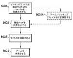
ピッキングフェイス210を配置するために、ローバー110は、上記のものと実質的に類似の方法でピッキングフェイスを棚からローバー110に移送するように位置決めされる(図16、ブロック6001)。上記のように、ある態様では、ローバー110は、ピッキングフェイスを保持位置にさらに位置合せするために(またはアームをピッキングフェイスに位置合せするために)矢印297の方向にローバーの伸縮アームが一体となって移動させられる、たとえば、ピッキングフェイス保持位置に対する伸縮アームの高精度位置決めである、矢印297の方向における位置調整を含む(図16、ブロック6001A)。図13Bに図示されているように、積載ベイ200のピッキングフェイス支持表面200Sを棚140の支持表面(または平面)140SPLと実質的に位置合せするために、積載ベイ200が矢印298の方向に移動させられる(図16、ブロック6002)。フィンガ900Fが、たとえば図14Aに示されている収縮位置にまで回転される(理解できるように、1つまたは複数の押出部材900Tと1つまたは複数のフィンガ900Fとの間におけるピッキングフェイスの把持は、1つまたは複数のフィンガ900Fの移動を可能にするために充分に解除される)(図16、ブロック6003)。押出部材900Tがピッキングフェイス210を積載ベイのピッキングフェイス支持表面200Sから棚140または他のピッキングフェイス保持位置の支持表面140SPLへ押し出す、または摺動させるように伸縮アーム802A、802Bが矢印299Aの方向に伸長される(図16、ブロック6004)。ある態様では、押出部材900Tは、ピッキングフェイスを矢印299Aの方向にさらに位置決めするために、伸縮アーム802A、802Bの伸縮中および/または伸縮後に矢印299Aの方向に移動させられる。ふたたび図8を参照して、ローバー110の例示的なピッキングフェイス構築動作が説明される。ローバー110は、上記のものと実質的に類似の方法で1つまたは複数の第1ピッキングフェイス210(図2C)を棚からローバー110に移送するように位置決めされる(図18、ブロック7000)。図13Aに図示されているように、アーム802A、802Bを、(隣り合うケースユニット/ピッキングフェイスの間の空間SPに合うように)1つまたは複数の第1ピッキングフェイス210と位置合せするために、アーム802A、802B間の間隔D1’は、矢印297の方向に調節される(図18、ブロック7001)。上記のように、ある態様では、ローバー110は、伸縮アーム802A、802Bを1つまたは複数の第1のピッキングフェイス210にさらに位置合せするために矢印297の方向にローバーの伸縮アームが一体となって移動させられる、たとえば、ピッキングフェイス保持位置に対する伸縮アームの高精度位置決めである、矢印297の方向における位置調整を含む(図18、ブロック7001A)。図13Bに図示されているように、積載ベイ200のピッキングフェイス支持表面200Sを棚140の支持表面(または平面)140SPLと実質的に位置合せするために、積載ベイ200が矢印298の方向に移動させられる(図18、ブロック7002)。伸縮アーム802A、802Bは、図15のブロック5003〜5007に関する上記の方法で、1つまたは複数の第1のピッキングフェイス210を積載ベイに移送するために、矢印299A、299Bの方向に伸長および収縮する(図18、ブロック7003)。1つまたは複数の第1のピッキングフェイス210が積載ベッド200内に位置決めされると、1つまたは複数の第2のピッキングフェイス210Xの積載ベイ200への移送(図2C)のために、ローバー110はピッキング構造物を横断し、別のピッキングフェイス保持位置に対して位置決めされる(図18、ブロック7000)。伸縮アーム802A、802Bを他のピッキングフェイス保持位置の1つまたは複数の第2のピッキングフェイス210Xに位置合せするために、積載ベイ内の1つまたは複数の第1のピッキングフェイス210が非挟持とされ、伸縮アーム802A、802B間の間隔が調節される(図18、ブロック7001)および/または位置調整される(図18、ブロック7001A)。理解できるように、既に積載ベッド200上で保持されている1つまたは複数の第1のピッキングフェイス210は、伸縮アームが位置調整される時に、伸縮アームにより矢印297の方向に移動させられる。図13Bに図示されているように、積載ベイ200のピッキングフェイス支持表面200Sを棚140の支持表面(または平面)140SPLと実質的に位置合せするために、積載ベイ200が矢印298の方向に移動させられる(図18、ブロック7002)。伸縮アーム802A、802Bは、図15のブロック5003〜5007に関する上記の方法で、1つまたは複数の第2のピッキングフェイス210Xを積載ベイに移送するために、矢印299A、299Bの方向に伸長および収縮する(図18、ブロック7003)。理解できるように、押出部材900Tが積載ベイ200内の1つまたは複数の第1のピッキングフェイスに接触しないように(および/または押出部材900Tが、積載ベイ200内のピッキングフェイスに接触しないように位置決めされるように)1つまたは複数の第2のピッキングフェイス210Xの積載ベイ200への移送中に、伸縮アーム802A、802Bは1つまたは複数の第1のピッキングフェイスの側面から離間してもよい。1つまたは複数の第2のピッキングフェイス210Xが積載ベッド200内に位置するとき、押出部材900Tおよび/またはフィンガ900Fは、矢印299A、299Bの方向に1つまたは複数の第1および第2のピッキングフェイスを互いに寄せる(snug)ために使用される。ピッキングフェイス210、210Xの積載ベッドへの移送に関する上記のものと実質的に反対の方法で、1つまたは複数の第1および第2のピッキングフェイス210、210Xがローバーによって、一体となって移送され、ピッキングフェイス保持位置に一体となって(または2つ以上のピッキングフェイス保持位置に別々に)配置される。 To place the picking
開示される実施形態の1つまたは複数の態様によれば、自律型搬送車両が提供される。自律型搬送車両は、積載ベッド、および積載ベッド内に設置され、積載ベッドへおよび積載ベッドからピッキングフェイスを搬送するために、第1の軸に沿って伸長するように構成されたエンドエフェクタを含み、エンドエフェクタは、少なくとも1つの移送アーム、および少なくとも1つの移送アームから第1の軸と略垂直な第2の軸に沿って延伸するフィンガを含み、フィンガはピッキングフェイスの下からピッキングフェイスを支持するように構成されている。 According to one or more aspects of the disclosed embodiments, an autonomous transport vehicle is provided. The autonomous transport vehicle includes a loading bed and an end effector that is installed within the loading bed and is configured to extend along a first axis to transport the picking face to and from the loading bed. The end effector includes at least one transfer arm and a finger extending from at least one transfer arm along a second axis approximately perpendicular to the first axis, the finger supporting the picking face from underneath the picking face. It is configured to do.
開示される実施形態の1つまたは複数の態様によれば、少なくとも1つの移送アームが、ピッキングフェイスの対向する側面をまたいで伸長するように構成された2つの移送アームを含む。 According to one or more embodiments of the disclosed embodiments, at least one transfer arm comprises two transfer arms configured to extend across opposite sides of the picking face.
開示される実施形態の1つまたは複数の態様によれば、少なくとも1つの移送アームが伸縮移送アームである。 According to one or more embodiments of the disclosed embodiments, at least one transfer arm is a telescopic transfer arm.
開示される実施形態の1つまたは複数の態様によれば、少なくとも1つの移送アームのそれぞれが、少なくとも1つの移送アームの伸長および収縮をもたらすように構成されたベルト駆動部を含む。 According to one or more aspects of the disclosed embodiments, each of the at least one transfer arm includes a belt drive that is configured to provide extension and contraction of the at least one transfer arm.
開示される実施形態の1つまたは複数の態様によれば、フィンガが、ピッキングフェイス支持棚の支持表面間のピッチに相当する所定のピッチだけ互いに離間し、それによってフィンガが支持表面間に位置する空間を通過する。 According to one or more aspects of the disclosed embodiments, the fingers are separated from each other by a predetermined pitch corresponding to the pitch between the support surfaces of the picking face support shelves, whereby the fingers are located between the support surfaces. Pass through space.
開示される実施形態の1つまたは複数の態様によれば、自律型移送車両が、少なくとも1つの移送アームを自律型移送車両の長手方向軸に沿って移動させるように構成された駆動部を含む。 According to one or more aspects of the disclosed embodiments, the autonomous transfer vehicle includes a drive unit configured to move at least one transfer arm along the longitudinal axis of the autonomous transfer vehicle. ..
開示される実施形態の1つまたは複数の態様によれば、自律型移送車両が、少なくとも1つの移送アームのそれぞれを、他の少なくとも1つの移送アームから独立して自律型移送車両の長手方向軸に沿って移動させるように構成された駆動部を含む。 According to one or more aspects of the disclosed embodiment, the autonomous transfer vehicle has each of the at least one transfer arm independent of the other at least one transfer arm along the longitudinal axis of the autonomous transfer vehicle. Includes a drive unit configured to move along.
開示される実施形態の1つまたは複数の態様によれば、自律型移送車両が、エンドエフェクタを第1の軸に略垂直な方向に移動させるように構成された駆動部を含む。 According to one or more embodiments of the disclosed embodiments, the autonomous transfer vehicle includes a drive unit configured to move the end effector in a direction substantially perpendicular to the first axis.
開示される実施形態の1つまたは複数の態様によれば、駆動部が、自律型移送車両を積み重ねられた保管棚の複数のレベルにアクセス可能にするために、エンドエフェクタを第1の軸に略垂直な方向に移動させるように構成される。 According to one or more aspects of the disclosed embodiments, the end effector is on the first axis in order to allow the drive unit to access multiple levels of the stacked storage shelves for the autonomous transfer vehicle. It is configured to move in a substantially vertical direction.
開示される実施形態の1つまたは複数の態様によれば、フィンガが、少なくとも1つの搬送アームに固定されて取り付けられる。 According to one or more aspects of the disclosed embodiments, the fingers are fixed and attached to at least one transport arm.
開示される実施形態の1つまたは複数の態様によれば、フィンガが、延伸位置および収縮位置間における移動のために、少なくとも1つの移送アームに移動可能に取り付けられ、延伸位置にあるとき、フィンガは少なくとも1つの移送アームから第2の軸に沿って延伸する。 According to one or more aspects of the disclosed embodiments, the finger is movably attached to at least one transfer arm for movement between the stretch and contraction positions and is in the stretch position. Extends from at least one transfer arm along a second axis.
開示される実施形態の1つまたは複数の態様によれば、保管および取出システムが提供される。保管および取出システムは、積載ベッド、および積載ベッド内に設置され、積載ベッドへおよび積載ベッドからピッキングフェイスを搬送するために、第1の軸に沿って伸長するように構成されたエンドエフェクタを含む、少なくとも1つの自律型移送車両、少なくとも1つの自律型移送車両がピッキング通路を通って走行することを可能にするように構成された、少なくとも1つのピッキング通路、および少なくとも1つのピッキング通路に近接して位置する、少なくとも1つの保管棚を含み、少なくとも1つの保管棚は、第2の軸に沿って延在する、互いに離間したピッキングフェイス支持表面を有し、第2の軸は第1の軸に略垂直であり、エンドエフェクタは、第2の軸に沿って延伸し、フィンガをピッキングフェイス支持表面で挟みこむことを可能にするように構成されたフィンガを含む。 According to one or more aspects of the disclosed embodiments, a storage and retrieval system is provided. The storage and retrieval system includes a loading bed and an end effector installed within the loading bed and configured to extend along a first axis to transport the picking face to and from the loading bed. In close proximity to at least one autonomous transfer vehicle, at least one picking passage configured to allow at least one autonomous transfer vehicle to travel through the picking passage, and at least one picking passage. Containing at least one storage shelf, the at least one storage shelf has a picking face support surface that extends along a second axis and is spaced apart from each other, the second axis being the first axis. Approximately perpendicular to, the end effector includes a finger that extends along a second axis and is configured to allow the finger to be sandwiched between the picking face support surfaces.
開示される実施形態の1つまたは複数の態様によれば、エンドエフェクタが、少なくとも1つの移送アーム、および少なくとも1つの移送アームから延伸するフィンガを含む。 According to one or more embodiments of the disclosed embodiments, the end effector comprises at least one transfer arm and a finger extending from at least one transfer arm.
開示される実施形態の1つまたは複数の態様によれば、少なくとも1つの移送アームが、ピッキングフェイスの対向する側面をまたいで伸長するように構成された2つの移送アームを含む。 According to one or more embodiments of the disclosed embodiments, at least one transfer arm comprises two transfer arms configured to extend across opposite sides of the picking face.
開示される実施形態の1つまたは複数の態様によれば、少なくとも1つの自律型移送車両が、少なくとも1つの移送アームを自律型移送車両の長手方向軸に沿って移動させるように構成された駆動部を含む。 According to one or more aspects of the disclosed embodiments, a drive configured such that at least one autonomous transfer vehicle moves at least one transfer arm along the longitudinal axis of the autonomous transfer vehicle. Including part.
開示される実施形態の1つまたは複数の態様によれば、少なくとも1つの自律型移送車両が、少なくとも1つの移送アームのそれぞれを、他の少なくとも1つの移送アームから独立して自律型移送車両の長手方向軸に沿って移動させるように構成された駆動部を含む。 According to one or more aspects of the disclosed embodiments, at least one autonomous transfer vehicle of the autonomous transfer vehicle, each of the at least one transfer arm independently of the other at least one transfer arm. Includes a drive unit configured to move along a longitudinal axis.
開示される実施形態の1つまたは複数の態様によれば、エンドエフェクタが伸縮エンドエフェクタである。 According to one or more embodiments of the disclosed embodiments, the end effector is a telescopic end effector.
開示される実施形態の1つまたは複数の態様によれば、エンドエフェクタが少なくとも1つの移送アームを含み、少なくとも1つの移送アームのそれぞれは、エンドエフェクタの伸長および収縮をもたらすように構成されたベルト駆動部を含む。 According to one or more embodiments of the disclosed embodiments, the end effector comprises at least one transfer arm, each of which is a belt configured to provide extension and contraction of the end effector. Includes drive unit.
開示される実施形態の1つまたは複数の態様によれば、フィンガが支持表面間に位置する空間を通過するように、フィンガが、ピッキングフェイス支持表面間のピッチに相当する所定のピッチだけ互いに離間する。 According to one or more embodiments of the disclosed embodiments, the fingers are separated from each other by a predetermined pitch corresponding to the pitch between the picking face support surfaces so that the fingers pass through a space located between the support surfaces. To do.
開示される実施形態の1つまたは複数の態様によれば、少なくとも1つの自律型移送車両が、エンドエフェクタを第1の軸に略垂直な方向に移動させるように構成された駆動部を含む。 According to one or more embodiments of the disclosed embodiments, at least one autonomous transfer vehicle includes a drive unit configured to move the end effector in a direction substantially perpendicular to the first axis.
開示される実施形態の1つまたは複数の態様によれば、駆動部が、少なくとも1つの自律型移送車両を積み重ねられた保管棚の複数のレベルにアクセス可能にするために、エンドエフェクタを第1の軸に略垂直な方向に移動させるように構成される。 According to one or more embodiments of the disclosed embodiments, the drive unit first sets the end effector to allow access to multiple levels of stacked storage shelves for at least one autonomous transfer vehicle. It is configured to move in a direction approximately perpendicular to the axis of.
開示される実施形態の1つまたは複数の態様によれば、フィンガがエンドエフェクタに固定されて取り付けられる。 According to one or more embodiments of the disclosed embodiments, the fingers are fixed and attached to the end effector.
開示される実施形態の1つまたは複数の態様によれば、フィンガが、延伸位置および収縮位置間における移動のためにエンドエフェクタに移動可能に取り付けられ、延伸位置にあるとき、フィンガはエンドエフェクタから第2の軸に沿って延伸する。 According to one or more aspects of the disclosed embodiments, when the finger is movably attached to the end effector for movement between the stretch and contraction positions and is in the stretch position, the finger is from the end effector. Stretch along the second axis.
開示される実施形態の1つまたは複数の態様によれば、保管および取出システム内においてピッキングフェイスを移送する方法が提供され、保管および取出システムは、少なくとも自律型移送車両、少なくとも1つの自律型移送車両が少なくとも1つのピッキング通路に沿って走行することを可能にするように構成されたピッキング通路デッキを有する、少なくとも1つのピッキング通路、および少なくとも1つのピッキング通路に近接して設置された、少なくとも1つの保管棚を含んでいる。方法は、エンドエフェクタのアームがピッキングフェイスの対向する側面をまたいで伸長するように、少なくとも1つの自律型移送車両のエンドエフェクタを少なくとも1つの保管棚内に所定の距離だけ伸長させること、エンドエフェクタのフィンガが、エンドエフェクタの伸長軸に略垂直な方向で、少なくとも保管棚のピッキングフェイス支持表面にさしはさまれ、ピッキングフェイス支持表面の下方にあるように、エンドエフェクタを下降させること、フィンガをピッキングフェイスの下に位置決めすること、およびフィンガがピッキングフェイスの重量を支持して、ピッキングフェイスを少なくとも1つの保管棚から上昇させることを含む。 According to one or more aspects of the disclosed embodiments, a method of transferring the picking face within the storage and retrieval system is provided, the storage and retrieval system being at least an autonomous transfer vehicle, at least one autonomous transfer. At least one picking aisle, with a picking aisle deck configured to allow the vehicle to travel along at least one picking aisle, and at least one installed in close proximity to at least one picking aisle. Includes two storage shelves. The method is to extend the end effector of at least one autonomous transfer vehicle by a predetermined distance into at least one storage shelf so that the arm of the end effector extends across the opposite sides of the picking face. Lowering the end effector so that the finger is at least sandwiched between the picking face support surface of the storage shelf and below the picking face support surface in a direction approximately perpendicular to the extension axis of the end effector. Includes positioning underneath the picking face, and the finger supporting the weight of the picking face to lift the picking face from at least one storage shelf.
開示される実施形態の1つまたは複数の態様によれば、フィンガをピッキングフェイスの下に位置決めすることが、エンドエフェクタの1つまたは複数のアームをピッキングフェイスのそれぞれの側面に向けて移動させることを含む。 According to one or more aspects of the disclosed embodiments, positioning the finger under the picking face causes one or more arms of the end effector to move towards each side of the picking face. including.
開示される実施形態の1つまたは複数の態様によれば、エンドエフェクタがアームを含み、方法は、アームがピッキングフェイスの対向する側面に沿って設置された棚の空間内に接触せずに挿入されるように、アーム間の間隔を調節することをさらに含む。 According to one or more embodiments of the disclosed embodiments, the end effector comprises an arm, the method of which the arm is inserted without contact into the space of a shelf placed along the opposing sides of the picking face. It further includes adjusting the spacing between the arms so that it is done.
1つまたは複数の態様によれば、少なくとも1つの保管棚は積み重ねられた保管棚を含み、方法は、エンドエフェクタを積み重ねられた保管棚の1つのレベルへと持ち上げるまたは下降させることをさらに含む。 According to one or more aspects, the at least one storage ledge comprises a stacked storage ledge, and the method further comprises lifting or lowering the end effector to one level of the stacked vaults.
開示される実施形態の1つまたは複数の態様によれば、複数の積み重ねられた保管棚が、共通のピッキング通路デッキから少なくとも1つの自律型移送車両によってアクセス可能である。 According to one or more embodiments of the disclosed embodiments, multiple stacked storage shelves are accessible by at least one autonomous transfer vehicle from a common picking aisle deck.
開示される実施形態の1つまたは複数の態様によれば、自律型移送車両が、積載領域を形成するフレームと、フレームに移動可能に取り付けられた伸縮アームであって、各伸縮アームが、積載領域への、または積載領域からの少なくとも1つのピッキングフェイスの移送をもたらすために、伸長軸に沿って、フレームに対して伸長および収縮するように、伸長軸に対して傾斜した少なくとも1つの方向において、フレームに対して横断するように構成された、伸縮アームと、各伸縮アームから延伸する少なくとも1つのタブと、を備え、少なくとも1つのタブが伸長および収縮の方向と交差する方向に延伸し、伸縮アームのうちの1つの少なくとも1つのタブが、もう1つの伸縮アームの少なくとも1つのタブに対向している。 According to one or more embodiments of the disclosed embodiments, the autonomous transfer vehicle is a frame forming a loading area and telescopic arms movably attached to the frames, each telescopic arm being loaded. In at least one direction tilted with respect to the extension axis so as to extend and contract with respect to the frame along the extension axis to result in transfer of at least one picking face to or from the loading area. A telescopic arm configured to traverse the frame and at least one tab extending from each telescopic arm, the at least one tab extending in a direction intersecting the extension and contraction directions. At least one tab of the telescopic arm faces at least one tab of the other telescopic arm.
開示される実施形態の1つまたは複数の態様によれば、少なくとも1つの方向が、鉛直および水平方向の1つまたは複数である。 According to one or more aspects of the disclosed embodiments, at least one direction is one or more in the vertical and horizontal directions.
開示される実施形態の1つまたは複数の態様によれば、自律型移送車両が、伸縮アームの横断、ならびに伸縮アームの伸長および収縮をもたらすために、伸縮アームに接続された3自由度の駆動装置をさらに備える。 According to one or more embodiments of the disclosed embodiments, the autonomous transfer vehicle is driven by three degrees of freedom connected to the telescopic arm to provide crossing of the telescopic arm and extension and contraction of the telescopic arm. Further equipped with a device.
開示される実施形態の1つまたは複数の態様によれば、各伸縮アームが、変化可能な伸長および収縮の位置を有するように、伸縮アーム間の距離は変化な距離である。 According to one or more embodiments of the disclosed embodiments, the distance between the telescopic arms is a variable distance so that each telescopic arm has a variable extension and contraction position.
開示される実施形態の1つまたは複数の態様によれば、各伸縮アームが自由端および自由端に取り付けられた回転可能なフィンガを含み、回転可能なフィンガが、少なくとも1つのピッキングフェイスに接触しないような収縮位置と、少なくとも1つのピッキングフェイスの鉛直面に係合し、少なくとも1つのピッキングフェイスの積載領域への移送を少なくとももたらすような展開位置との間で移動可能である。 According to one or more embodiments of the disclosed embodiments, each telescopic arm comprises a free end and a rotatable finger attached to the free end, the rotatable finger not contacting at least one picking face. It is possible to move between such a contraction position and an unfolding position that engages the vertical faces of at least one picking face and results in at least transfer of the at least one picking face to the loading area.
開示される実施形態の1つまたは複数の態様によれば、各伸縮アームが、少なくともそれぞれのフィンガの作動をもたらすために、無線制御モジュールを含む。 According to one or more embodiments of the disclosed embodiments, each telescopic arm comprises a radio control module to provide at least the operation of its respective finger.
開示される実施形態の1つまたは複数の態様によれば、各伸縮アームが、フィンガに対向する、移動可能な押出部材を含み、押出部材は移動可能な押出部材とフィンガとの間でピッキングフェイスを少なくとも挟持および解放するために、フィンガに向かって、およびフィンガから離れるように直線移動するように構成されている。 According to one or more embodiments of the disclosed embodiments, each telescopic arm comprises a movable extrusion member facing the finger, which is a picking face between the movable extrusion member and the finger. Is configured to move linearly towards and away from the finger, at least to pinch and release.
開示される実施形態の1つまたは複数の態様によれば、各伸縮アームが、少なくとも、移動可能な押出部材の作動をもたらすための無線制御モジュールを含む。 According to one or more embodiments of the disclosed embodiments, each telescopic arm comprises at least a radio control module for providing operation of a movable extrusion member.
開示される実施形態の1つまたは複数の態様によれば、少なくとも1つのピッキングフェイスのサイズに関わりなく少なくとも1つのピッキングフェイスの全積載領域における位置調整をもたらすために、各移送アームが、積載領域のピッキングフェイス支持平面に略平行な平面において横断する。 According to one or more aspects of the disclosed embodiments, each transfer arm has a loading area to provide position adjustment in the entire loading area of at least one picking face regardless of the size of the at least one picking face. Cross in a plane approximately parallel to the picking face support plane of.
開示される実施形態の1つまたは複数の態様によれば、各伸縮アームが、伸縮アームから伸長軸に略垂直な第2の軸に沿って延伸するフィンガを含み、フィンガが少なくとも1つのピッキングフェイスを少なくとも1つのピッキングフェイスの下から支持するように構成される。 According to one or more aspects of the disclosed embodiments, each telescopic arm comprises a finger extending from the telescopic arm along a second axis substantially perpendicular to the extension axis, the finger being at least one picking face. Is configured to support from underneath at least one picking face.
開示される実施形態の1つまたは複数の態様によれば、フィンガが、ピッキングフェイス支持棚の支持表面の間のピッチに相当する所定のピッチで、前記フィンガが支持表面の間に位置する空間を通過するように互いに離間している。 According to one or more aspects of the disclosed embodiments, the fingers provide a space in which the fingers are located between the support surfaces at a predetermined pitch corresponding to the pitch between the support surfaces of the picking face support shelves. They are separated from each other so that they can pass through.
開示される実施形態の1つまたは複数の態様によれば、フィンガが、少なくとも1つの搬送アームに固定されて取り付けられる。 According to one or more aspects of the disclosed embodiments, the fingers are fixed and attached to at least one transport arm.
開示される実施形態の1つまたは複数の態様によれば、フィンガが、延伸位置および収縮位置間における移動のために、少なくとも1つの移送アームに移動可能に取り付けられ、延伸位置にあるとき、フィンガは少なくとも1つの移送アームから第2の軸に沿って延伸する。 According to one or more aspects of the disclosed embodiments, the finger is movably attached to at least one transfer arm for movement between the stretch and contraction positions and is in the stretch position. Extends from at least one transfer arm along a second axis.
開示される実施形態の1つまたは複数の態様によれば、少なくとも1つのタブが、伸縮アームの鉛直移動によってピッキングフェイスに係合する。 According to one or more embodiments of the disclosed embodiments, at least one tab engages the picking face by vertical movement of the telescopic arm.
開示される実施形態の1つまたは複数の態様によれば、保管および取出システムが、少なくとも1つの自律型搬送車両と、少なくとも1つのピッキング通路と、少なくとも1つの保管棚とを含み、少なくとも1つの自律型搬送車両が、積載領域を形成するフレームと、フレームに移動可能に取り付けられた伸縮アームであって、各伸縮アームが、伸長軸に沿って、フレームに対して伸長および収縮するように、伸長軸に対し傾斜した少なくとも1つの方向において、フレームに対して横断するように構成された、伸縮アームと、を含み、少なくとも1つのピッキング通路が、少なくとも1つ自律型搬送車両の、ピッキング通路を通る走行を可能にするように構成され、少なくとも1つの保管棚が、少なくとも1つのピッキング通路に隣接して位置し、伸縮アームの伸長および収縮が、少なくとも1つの保管棚と積載領域との間における少なくとも1つのピッキングフェイスの移送をもたらす。 According to one or more embodiments of the disclosed embodiments, the storage and retrieval system comprises at least one autonomous transport vehicle, at least one picking aisle, and at least one storage shelf. An autonomous transport vehicle is a frame forming a loading area and telescopic arms movably attached to the frame so that each telescopic arm extends and contracts with respect to the frame along an extension axis. At least one picking aisle, including a telescopic arm configured to traverse the frame in at least one direction inclined with respect to the extension axis, provides the picking aisle of at least one autonomous transport vehicle. Configured to allow travel through, at least one storage shelf is located adjacent to at least one picking aisle, and extension and contraction of the telescopic arm is between at least one storage shelf and the loading area. It results in the transfer of at least one picking face.
開示される実施形態の1つまたは複数の態様によれば、少なくとも1つの保管棚が、少なくとも1つのピッキング通路の共通の走行表面からアクセス可能である、2つ以上の積み重ねられた保管棚を含む。 According to one or more aspects of the disclosed embodiments, at least one storage shelf comprises two or more stacked storage shelves accessible from a common running surface of at least one picking aisle. ..
開示される実施形態の1つまたは複数の態様によれば、少なくとも1つの方向が、鉛直および水平方向の1つまたは複数である。 According to one or more aspects of the disclosed embodiments, at least one direction is one or more in the vertical and horizontal directions.
開示される実施形態の1つまたは複数の態様によれば、少なくとも1つの自律型搬送車両が、伸縮アームの横断、ならびに伸縮アームの伸長および収縮をもたらすために、伸縮アームに接続された3自由度の駆動装置を含む。 According to one or more embodiments of the disclosed embodiments, at least one autonomous transport vehicle has three degrees of freedom connected to the telescopic arm to provide crossing of the telescopic arm and extension and contraction of the telescopic arm. Includes degree of freedom drive.
開示される実施形態の1つまたは複数の態様によれば、各伸縮アームが、変化可能な伸長および収縮の位置を有するように、伸縮アーム間の距離は変化可能な距離である。 According to one or more embodiments of the disclosed embodiments, the distance between the telescopic arms is a variable distance so that each telescopic arm has a variable extension and contraction position.
開示される実施形態の1つまたは複数の態様によれば、各伸縮アームが、伸縮アームから伸長軸に略垂直な第2の軸に沿って延伸するフィンガを含み、フィンガが、少なくとも1つのピッキングフェイスを少なくとも1つのピッキングフェイスの下から支持するように構成される。 According to one or more embodiments of the disclosed embodiments, each telescopic arm comprises a finger extending from the telescopic arm along a second axis substantially perpendicular to the extension axis, the finger comprising at least one picking. The face is configured to support from underneath at least one picking face.
開示される実施形態の1つまたは複数の態様によれば、少なくとも1つの自律型移送車両と、少なくとも1つのピッキング通路と、少なくとも1つの保管棚を含む保管および取出システム内においてピッキングフェイスを移送する方法であって、少なくとも1つのピッキング通路が、少なくとも1つの自律型移送車両が少なくとも1つのピッキング通路に沿って走行することを可能にするように構成されたピッキング通路デッキを有し、少なくとも1つの保管棚が少なくとも1つのピッキング通路に隣接して設置され、方法が、少なくとも1つの自律型搬送車両のフレームに対し、少なくとも1つの軸に沿って、少なくとも1つの自律型搬送車両の伸縮アームを、伸縮アームが少なくとも1つの保管棚の所定の場所に応じた位置に設置されるように、位置決めすることと、少なくとも1つの軸が他の軸に対して傾斜し、伸縮アームがピッキングフェイスの対向する側面をまたいで伸長するように、フレームに対し、他の軸に沿って伸縮アームを伸長させることと、他の軸に沿った伸縮アームの収縮によって、少なくとも1つの自律型搬送車両の積載領域内にピッキングフェイスを移送することと、を含む。 According to one or more embodiments of the disclosed embodiments, the picking face is transferred within a storage and retrieval system that includes at least one autonomous transfer vehicle, at least one picking passage, and at least one storage shelf. A method, wherein at least one picking passage has a picking passage deck configured to allow at least one autonomous transfer vehicle to travel along at least one picking passage, at least one. Storage shelves are installed adjacent to at least one picking passage, and the method is to attach at least one autonomous transport vehicle telescopic arm along at least one axis to the frame of at least one autonomous transport vehicle. Positioning so that the telescopic arm is placed in a predetermined position on at least one storage shelf, and at least one axis tilted relative to the other axis, with the telescopic arm facing the picking face. By extending the telescopic arm along the other axis and contracting the telescopic arm along the other axis with respect to the frame so as to extend across the sides, within the loading area of at least one autonomous transport vehicle. Includes transferring the picking face to.
開示される実施形態の1つまたは複数の態様によれば、ピッキングフェイスを積載領域内に移送することが、伸縮アームに取り付けられた回転可能なフィンガを用いてピッキングフェイスを積載領域に引き込むことを含む。 According to one or more aspects of the disclosed embodiments, transferring the picking face into the loading area causes the picking face to be pulled into the loading area using a rotatable finger attached to a telescopic arm. Including.
開示される実施形態の1つまたは複数の態様によれば、方法が、伸縮アーム上に設置された移動可能な押出部材を用いて、フィンガに対してピッキングフェイスを挟持することをさらに含む。 According to one or more aspects of the disclosed embodiments, the method further comprises sandwiching the picking face against the fingers using a movable extrusion member installed on the telescopic arm.
開示される実施形態の1つまたは複数の態様によれば、方法が、少なくとも回転可能なフィンガの作動を、無線を通じてもたらすことをさらに含む。 According to one or more aspects of the disclosed embodiments, the method further comprises providing at least rotatable finger operation via radio.
開示される実施形態の1つまたは複数の態様によれば、伸縮アームを位置決めすることが、伸縮アームを2つの軸に沿って位置決めすることを含み、2つの軸は互いに対して略垂直である。 According to one or more embodiments of the disclosed embodiments, positioning the telescopic arm comprises positioning the telescopic arm along two axes, the two axes being substantially perpendicular to each other. ..
開示される実施形態の1つまたは複数の態様によれば、自律型搬送車両が、積載領域を形成するフレームと、フレームに移動可能に取り付けられた伸縮アームであって、各伸縮アームが、積載領域への、または積載領域からの少なくとも1つのピッキングフェイスの移送をもたらすために、伸長軸に沿って、フレームに対して伸長および収縮するように、伸長軸に対して傾斜した少なくとも1つの方向において、フレームに対して横断するように構成された、伸縮アームと、各伸縮アームから延伸する少なくとも1つのタブと、を備え、前記少なくとも1つのタブが、前記伸縮アームの伸長および収縮の方向に移動可能であり、前記伸縮アームの伸長および収縮と関わりなく、前記伸長および収縮の方向において、前記少なくとも1つのピッキングフェイスの位置調整をもたらすために、それぞれの伸縮アームに取り付けられている。 According to one or more embodiments of the disclosed embodiments, the autonomous transport vehicle is a frame forming a loading area and telescopic arms movably attached to the frames, each telescopic arm being loaded. In at least one direction tilted with respect to the extension axis so as to extend and contract with respect to the frame along the extension axis to provide transfer of at least one picking face to or from the loading area. The telescopic arm, configured to traverse the frame, and at least one tab extending from each telescopic arm, the at least one tab moving in the direction of extension and contraction of the telescopic arm. It is possible and attached to each telescopic arm to provide position adjustment of the at least one picking face in the direction of the telescopic and contraction, regardless of the extension and contraction of the telescopic arm.
開示される実施形態の1つまたは複数の態様によれば、少なくとも1つのタブが伸長および収縮の方向に交差する方向に延伸し、伸縮アームのうちの1つの少なくとも1つのタブが、もう1つの伸縮アーム上の少なくとも1つのタブに対向している。 According to one or more aspects of the disclosed embodiments, at least one tab extends in a direction that intersects in the direction of extension and contraction, and at least one tab of the telescopic arm is another. Facing at least one tab on the telescopic arm.
上記記載は、開示される実施形態の態様の例示にすぎないことが理解されるべきである。当業者によって、様々な代替例および修正例が、開示される実施形態の態様から逸脱することなく案出され得る。従って、開示された実施形態の態様は、添付の請求項の範囲に該当する、そのような代替例、修正例、および変形例のすべてを含むことを意図している。さらに、異なる特徴が、相互に異なる従属または独立請求項に詳述されるという一事実は、これらの特徴の組み合わせを有利に使用することが出来ないということを意味せず、そのような組み合わせは、本発明の態様の範囲内に留まる。 It should be understood that the above description is merely an example of aspects of the disclosed embodiments. Various alternatives and modifications can be devised by one of ordinary skill in the art without departing from the aspects of the disclosed embodiments. Accordingly, the disclosed embodiments are intended to include all such alternatives, modifications, and variations that fall within the scope of the appended claims. Moreover, the fact that different features are detailed in different dependent or independent claims does not mean that the combination of these features cannot be used in an advantageous manner, and such combinations , Stay within the scope of the aspects of the invention.
Claims (28)
Translated fromJapanese前記フレームに直立して取り付けられた少なくとも1つの直立マスト部材であって、前記フレームの前記積載領域に取り付けられ、前記積載ベイとともに前記フレームの前記積載領域を形成する少なくとも1つの直立マスト部材と、
少なくとも鉛直方向の移動のために前記少なくとも1つの直立マスト部材に移動可能に取り付けられた伸長アームであって、各伸長アームが、前記積載領域への、および前記積載領域からの少なくとも1つのピッキングフェイスの移送をもたらすために、伸長軸に沿って、前記フレームに対して伸長および収縮するように構成され、前記積載領域が、前記伸長軸と交差する少なくとも1つの方向において、前記フレームの前記積載領域に対して移動可能な積載位置調整横断部材を有する、伸長アームと
を備える自律ガイド型自律搬送車両。A frame forming a loading area with a loading bay with a picking face support plane,
And at least oneupstanding mast member mountedupright on the frame, mounted on the loading area of the frame, and at least oneupstanding mastmember forming the loading area of the framewith the loading bay,
Extendable arms movably attached to the at least oneupright mast member for movement inat least the vertical direction , each extension arm having at least one picking face to and from the loading area. The loading area of the frame is configured to extend and contract with respect to the frame along the extension axis so that the loading area intersects the extension axis in at least one direction. An autonomousguide- typeautonomous transport vehicle having an extension arm and a loading position adjusting crossing member that can be moved with respect to the vehicle.
前記少なくとも1つの自律ガイド型自律搬送車両が、
ピッキングフェイス支持平面を備える積載ベイを有する積載領域を形成するフレームと、
前記フレームに直立して取り付けられた少なくとも1つの直立マスト部材であって、前記フレームの前記積載領域に取り付けられ、前記積載ベイとともに前記フレームの前記積載領域を形成する少なくとも1つの直立マスト部材と、
少なくとも鉛直方向の移動のために前記少なくとも1つの直立マスト部材に移動可能に取り付けられた伸長アームであって、各伸長アームが、伸長軸に沿って、前記フレームに対して伸長および収縮するように構成され、前記積載領域が、前記伸長軸と交差する少なくとも1つの方向において、前記フレームの積載領域に対して移動可能な積載位置調整横断部材を有する、伸長アームと、
を含み、
前記少なくとも1つのピッキング通路が、前記少なくとも1つの自律ガイド型自律搬送車両の、前記ピッキング通路を通る走行を可能にするように構成され、
前記少なくとも1つの保管棚が、前記少なくとも1つのピッキング通路に隣接して位置し、
前記伸長アームの伸長および収縮が、前記少なくとも1つの保管棚と前記積載領域との間における少なくとも1つのピッキングフェイスの移送をもたらす、
保管および取出システム。A storage and retrieval system comprising at least one autonomouslyguidedautonomous transport vehicle, at least one picking aisle, and at least one storage shelf.
The at least one autonomousguide typeautonomous transport vehicle
A frame forming a loading area with a loading bay with a picking face support plane,
And at least oneupstanding mast member mountedupright on the frame, mounted on the loading area of the frame, and at least oneupstanding mastmember forming the loading area of the framewith the loading bay,
Extendable arms movably attached to the at least oneupright mast member for movementat least in the vertical direction , such that each extension arm extends and contracts with respect to the frame along the extension axis. An extension arm that is configured and has a loading position adjusting cross member that is movable relative to the loading area of the frame in at least one direction in which the loading area intersects the extension axis.
Including
The at least one picking aisle is configured to allow the at least one autonomousguidedautonomous transport vehicle to travel through the picking aisle.
The at least one storage shelf is located adjacent to the at least one picking aisle.
The extension and contraction of the extension arm results in the transfer of at least one picking face between the at least one storage shelf and the loading area.
Storage and retrieval system.
前記少なくとも1つの自律ガイド型自律搬送車両のフレームの積載領域に対し、少なくとも1つの軸に沿って、前記少なくとも1つの自律ガイド型自律搬送車両の伸長アームを、前記伸長アームが前記少なくとも1つの保管棚の所定の場所に応じた位置に設置されるように、位置決めすることであって、前記伸長アームが、前記フレームの前記積載領域に直立に取り付けられ、前記フレームの積載ベイとともに前記フレームの前記積載領域を形成する少なくとも1つの直立マスト部材に沿って、鉛直に位置決めされる、前記少なくとも1つの自律ガイド型自律搬送車両の伸長アームを位置決めすることと、
前記伸長アームがピッキングフェイスの対向する側面をまたいで伸長するように、前記伸長アームを伸長させることと、
前記伸長アームの収縮によって、前記少なくとも1つの自律ガイド型自律搬送車両の積載領域内に前記ピッキングフェイスを移送することと、
他の軸と交差する少なくとも1つの方向において、前記フレームの積載領域に対して他の軸に沿って前記積載領域の積載位置調整横断部材を移動させることと
を含む、
方法。At least one autonomousguidedautonomous transfer vehicle, and at least one picking passage, a method of transferring the picking face in a storage and removal systemand at least one storage rack, the at least one picking passage, The picking aisle deck is configured to allow the at least one autonomousguidedautonomous transport vehicle to travel along the at least one aisle, and the at least one storage shelf is said to be at least one. Installed adjacent to the picking aisle,
Loading area of the frame of the at least one autonomousguidedautonomous transfer vehicle to, along at least one axis, the extension arm of the at least one autonomousguidedautonomous transfer vehicle, storage said extension arm of the at least one Positioning the shelves so that they are placed in place in place, the extension arm is mountedupright in the loading area of theframe and, along with the loading bay of the frame, said of the frame. Positioning the extension arm of the at least one autonomouslyguidedautonomous transport vehicle, which isvertically positioned along at least oneupright mast memberforming a loading area,
Extending the extension arm so that the extension arm extends across the opposite sides of the picking face.
By contracting the extension arm, the picking face is transferred into the loading area of the at least one autonomousguide typeautonomous transport vehicle.
Including moving a loading position adjusting cross member of the loading area along the other axis with respect to the loading area of the frame in at least one direction intersecting the other axis.
Method.
前記フレームに直立に取り付けられた少なくとも1つの直立マスト部材であって、前記フレームの前記積載領域に取り付けられ、前記積載ベイとともに前記フレームの前記積載領域を形成する少なくとも1つの直立マスト部材と、
少なくとも鉛直方向の移動のために前記少なくとも1つの直立マスト部材に移動可能に取り付けられた伸長アームであって、各伸長アームが、前記積載領域への、および前記積載領域からの少なくとも1つのピッキングフェイスの移送をもたらすために、伸長軸に沿って、前記フレームに対して伸長および収縮するように構成され、前記積載領域が、前記伸長軸と交差する少なくとも1つの方向において、前記フレームに対して移動可能な積載位置調整横断部材を有する、伸長アームと
を備えた自律ガイド型自律搬送車両であって、
前記積載位置調整横断部材が、前記伸長アームの伸長および収縮と関わりなく、前記伸長軸と交差する方向において、前記少なくとも1つのピッキングフェイスの位置調整をもたらす、
自律ガイド型自律搬送車両。A frame forming a loading area with a loading bay with a picking face support plane,
And at least oneupstanding mast member attachedto the upright on the frame, mounted on the loading area of the frame, and at least oneupstanding mastmember forming the loading area of the framewith the loading bay,
Extendable arms movably attached to the at least oneupright mast member for movement inat least the vertical direction , each extension arm having at least one picking face to and from the loading area. It is configured to extend and contract with respect to the frame along the extension axis so that the loading area moves relative to the frame in at least one direction intersecting the extension axis. An autonomousguide- typeautonomous transport vehicle equipped with an extension arm having a possible loading position adjustment crossing member.
The loading position adjusting cross member provides position adjustment of the at least one picking face in a direction intersecting the extension axis regardless of the extension and contraction of the extension arm.
Autonomousguide typeautonomous transport vehicle.
Applications Claiming Priority (4)
| Application Number | Priority Date | Filing Date | Title |
|---|---|---|---|
| US201361877614P | 2013-09-13 | 2013-09-13 | |
| US61/877,614 | 2013-09-13 | ||
| US14/486,008US10894663B2 (en) | 2013-09-13 | 2014-09-15 | Automated storage and retrieval system |
| US14/486,008 | 2014-09-15 |
Related Parent Applications (1)
| Application Number | Title | Priority Date | Filing Date |
|---|---|---|---|
| JP2016542846ADivisionJP6523296B2 (en) | 2013-09-13 | 2014-09-15 | Automatic storage and retrieval system |
Related Child Applications (1)
| Application Number | Title | Priority Date | Filing Date |
|---|---|---|---|
| JP2020208823ADivisionJP7266571B2 (en) | 2013-09-13 | 2020-12-16 | AUTONOMOUSLY GUIDED AUTONOMOUS TRANSPORT VEHICLES, AUTOMATED STORAGE AND RETRIEVAL SYSTEMS INCLUDING AUTONOMOUSLY GUIDED AUTONOMOUS TRANSPORT VEHICLES, AND METHODS FOR AUTOMATED STORAGE AND RETRIEVAL SYSTEMS |
Publications (2)
| Publication Number | Publication Date |
|---|---|
| JP2019142723A JP2019142723A (en) | 2019-08-29 |
| JP6812491B2true JP6812491B2 (en) | 2021-01-13 |
Family
ID=52666526
Family Applications (3)
| Application Number | Title | Priority Date | Filing Date |
|---|---|---|---|
| JP2016542846AActiveJP6523296B2 (en) | 2013-09-13 | 2014-09-15 | Automatic storage and retrieval system |
| JP2019084735AActiveJP6812491B2 (en) | 2013-09-13 | 2019-04-25 | Methods for automatic storage and retrieval systems, including autonomous guided autonomous transport vehicles, autonomous guided autonomous transport vehicles, and automatic storage and retrieval systems. |
| JP2020208823AActiveJP7266571B2 (en) | 2013-09-13 | 2020-12-16 | AUTONOMOUSLY GUIDED AUTONOMOUS TRANSPORT VEHICLES, AUTOMATED STORAGE AND RETRIEVAL SYSTEMS INCLUDING AUTONOMOUSLY GUIDED AUTONOMOUS TRANSPORT VEHICLES, AND METHODS FOR AUTOMATED STORAGE AND RETRIEVAL SYSTEMS |
Family Applications Before (1)
| Application Number | Title | Priority Date | Filing Date |
|---|---|---|---|
| JP2016542846AActiveJP6523296B2 (en) | 2013-09-13 | 2014-09-15 | Automatic storage and retrieval system |
Family Applications After (1)
| Application Number | Title | Priority Date | Filing Date |
|---|---|---|---|
| JP2020208823AActiveJP7266571B2 (en) | 2013-09-13 | 2020-12-16 | AUTONOMOUSLY GUIDED AUTONOMOUS TRANSPORT VEHICLES, AUTOMATED STORAGE AND RETRIEVAL SYSTEMS INCLUDING AUTONOMOUSLY GUIDED AUTONOMOUS TRANSPORT VEHICLES, AND METHODS FOR AUTOMATED STORAGE AND RETRIEVAL SYSTEMS |
Country Status (5)
| Country | Link |
|---|---|
| US (3) | US10894663B2 (en) |
| JP (3) | JP6523296B2 (en) |
| KR (3) | KR102473726B1 (en) |
| CN (1) | CN105705441B (en) |
| WO (1) | WO2015038999A2 (en) |
Families Citing this family (78)
| Publication number | Priority date | Publication date | Assignee | Title |
|---|---|---|---|---|
| TWI680928B (en) | 2009-04-10 | 2020-01-01 | 美商辛波提克有限責任公司 | Vertical lift system and method for transferring uncontained case unit to and from a multilevel storage structure |
| US9321591B2 (en) | 2009-04-10 | 2016-04-26 | Symbotic, LLC | Autonomous transports for storage and retrieval systems |
| US8696010B2 (en)* | 2010-12-15 | 2014-04-15 | Symbotic, LLC | Suspension system for autonomous transports |
| US8965619B2 (en) | 2010-12-15 | 2015-02-24 | Symbotic, LLC | Bot having high speed stability |
| US9561905B2 (en) | 2010-12-15 | 2017-02-07 | Symbotic, LLC | Autonomous transport vehicle |
| US9187244B2 (en) | 2010-12-15 | 2015-11-17 | Symbotic, LLC | BOT payload alignment and sensing |
| US9499338B2 (en) | 2010-12-15 | 2016-11-22 | Symbotic, LLC | Automated bot transfer arm drive system |
| US11078017B2 (en) | 2010-12-15 | 2021-08-03 | Symbotic Llc | Automated bot with transfer arm |
| CN105705441B (en) | 2013-09-13 | 2018-04-10 | 西姆伯蒂克有限责任公司 | Autonomous transport car, the method for storing and fetching system and selection face being transmitted in the system |
| US9505556B2 (en)* | 2014-09-03 | 2016-11-29 | Ottos Consultants Ltd. | Storage system using lifting mechanism for collecting containers in desired sequence |
| US10214354B2 (en)* | 2014-12-18 | 2019-02-26 | Nextshift Robotics, Inc. | Method and system for automated transport of items |
| EP3192616B1 (en) | 2016-01-14 | 2024-09-25 | Jungheinrich AG | Robot to pick up and transport objects and method using such a robot |
| US9827669B2 (en)* | 2016-04-21 | 2017-11-28 | Fetch Robotics, Inc. | Robotic torso sensing system and method |
| US10138060B1 (en)* | 2016-06-22 | 2018-11-27 | Amazon Technologies, Inc. | Modular, multi-function robotic positioning system |
| EP3272679B1 (en)* | 2016-07-19 | 2020-10-21 | Dematic GmbH | Automatically centring load support for shuttle vehicles having a variable receiving width |
| FR3056565B1 (en)* | 2016-09-27 | 2021-01-08 | Savoye | DEVICE FOR GRIPPING LOADS OF VARIABLE SIZES AND PROCESS FOR ADAPTING THE CORRESPONDING GRIP WIDTH |
| CN106364831B (en)* | 2016-09-29 | 2018-06-19 | 三峡大学 | A kind of high position cargo fetching device |
| AT519098B1 (en)* | 2017-05-08 | 2018-04-15 | TELESCOPIC WITH ROLLING FINGER FOR LASER SUPPLEMENT | |
| AT519089B1 (en)* | 2017-05-08 | 2018-04-15 | Karl Dipl Ing Angleitner | TELESCOPIC LASER RECEIPT |
| DE102017122704A1 (en)* | 2017-09-29 | 2019-04-04 | Lr Intralogistik Gmbh | Device for load transfer |
| CN107720066A (en)* | 2017-09-30 | 2018-02-23 | 山东兰剑物流科技股份有限公司 | Cellular system and hopper storage radio frequency |
| FR3072371A1 (en)* | 2017-10-12 | 2019-04-19 | Exotec Solutions | SYSTEM FOR STORING AND TRANSPORTING OBJECTS STORED IN WAREHOUSE STORAGE |
| DE102017219432A1 (en)* | 2017-10-30 | 2019-05-02 | FB Industry Automation GmbH | Shelving system with shuttle vehicle |
| DE102017219431A1 (en)* | 2017-10-30 | 2019-05-02 | FB Industry Automation GmbH | Shelving system with shuttle vehicle |
| WO2019089923A1 (en)* | 2017-11-03 | 2019-05-09 | Labrador Systems, Inc. | Autonomous domestic robotic systems for item retrieval and transport |
| US12006143B2 (en)* | 2017-11-14 | 2024-06-11 | Hai Robotics Co., Ltd. | Handling robot |
| US12103771B2 (en) | 2017-11-14 | 2024-10-01 | Hai Robotics Co., Ltd. | Handling robot |
| US11396424B2 (en) | 2017-11-14 | 2022-07-26 | Hai Robotics Co., Ltd. | Handling robot |
| US11465840B2 (en) | 2017-11-14 | 2022-10-11 | Hai Robotics Co., Ltd. | Handling robot |
| MY188417A (en) | 2017-11-14 | 2021-12-08 | Hai Robotics Co Ltd | Automated guided vehicle designed for warehouse |
| US12330870B2 (en) | 2017-11-14 | 2025-06-17 | Hai Robotics Co., Ltd. | Handling robot |
| WO2019133944A1 (en)* | 2017-12-29 | 2019-07-04 | Avar Robotics Inc. | Robotic item retrieval and distribution system |
| JP6841262B2 (en)* | 2018-04-24 | 2021-03-10 | 株式会社ダイフク | Goods carrier |
| US11590997B1 (en) | 2018-08-07 | 2023-02-28 | Staples, Inc. | Autonomous shopping cart |
| US11630447B1 (en)* | 2018-08-10 | 2023-04-18 | Staples, Inc. | Automated guided vehicle for transporting objects |
| CN209160601U (en)* | 2018-09-07 | 2019-07-26 | 深圳市海柔创新科技有限公司 | a handling robot |
| US10435252B1 (en) | 2018-10-08 | 2019-10-08 | Becton Dickinson Rowa Germany Gmbh | Operating device for placing or retrieving bottle-like piece goods |
| EP3636565B1 (en)* | 2018-10-08 | 2024-02-21 | Becton Dickinson Rowa Germany GmbH | Operator's device for the storing and retrieving of bottle-like piece goods |
| US11597598B2 (en) | 2019-02-01 | 2023-03-07 | Hai Robotics Co., Ltd. | Handling robot |
| US11542135B2 (en) | 2019-02-01 | 2023-01-03 | Hai Robotics Co., Ltd. | Handling robot |
| DE102019104051A1 (en)* | 2019-02-18 | 2020-08-20 | A&A Logistik-Equipment GmbH & Co. KG | Driverless transport vehicle |
| JP7063295B2 (en)* | 2019-03-22 | 2022-05-09 | 株式会社ダイフク | Goods carrier |
| DE102019204762B4 (en)* | 2019-04-03 | 2024-11-07 | Audi Ag | load handling device for an automated warehouse |
| CN110203603A (en)* | 2019-07-01 | 2019-09-06 | 无锡凯乐士科技有限公司 | A kind of telescopic fork mechanism and shuttle |
| CN110255042A (en)* | 2019-07-22 | 2019-09-20 | 浙江凯乐士科技有限公司 | A kind of cargo fetching device, goods handling apparatus and system |
| CN111776559B (en) | 2019-09-09 | 2021-10-15 | 北京京东乾石科技有限公司 | warehouse shuttle |
| US11807451B2 (en) | 2019-09-17 | 2023-11-07 | Hai Robotics Co., Ltd. | Fork and carrying robot |
| CN211056639U (en)* | 2019-09-17 | 2020-07-21 | 深圳市海柔创新科技有限公司 | Fork and handling robot |
| KR102336620B1 (en) | 2019-09-23 | 2021-12-09 | 주식회사 티에스피지 | Telescopic fork Device for moving cart |
| JP7429289B2 (en)* | 2019-10-23 | 2024-02-07 | シャンハイ クイックトロン インテリジェント テクノロジー カンパニー リミテッド | Expanding/contracting device and transfer robot |
| IT201900019802A1 (en)* | 2019-10-25 | 2020-01-25 | Lhd S P A | Automated container handling system |
| US11407587B1 (en)* | 2019-11-04 | 2022-08-09 | Amazon Technologies, Inc. | Automated container retrieval and delivery systems |
| CN110844440A (en)* | 2019-12-19 | 2020-02-28 | 上海欣巴自动化科技有限公司 | Material taking mechanism of material box vehicle |
| CN110893969B (en)* | 2019-12-20 | 2020-10-30 | 上海企享企业服务股份有限公司 | A freight picks up floor truck for intelligent warehouse |
| US11697556B2 (en)* | 2020-02-07 | 2023-07-11 | Packsize Llc | Dynamic conveyor system for custom sized packaging |
| IT202000005632A1 (en)* | 2020-03-17 | 2021-09-17 | Automha S P A | Device for picking up and / or depositing items for automatic warehouses. |
| JP7332038B2 (en)* | 2020-04-30 | 2023-08-23 | 村田機械株式会社 | Traveling trolley and automated warehouse |
| CN113917894B (en)* | 2020-07-09 | 2024-04-19 | 讯芯电子科技(中山)有限公司 | Intelligent carrier and intelligent material storage management system |
| CN212711034U (en)* | 2020-07-30 | 2021-03-16 | 深圳市海柔创新科技有限公司 | Goods taking mechanism and carrying device |
| JP7444014B2 (en)* | 2020-10-02 | 2024-03-06 | トヨタ自動車株式会社 | Transportation system and transportation method |
| JP2023549279A (en)* | 2020-11-18 | 2023-11-22 | ザ ルービック テクノロジーズ インコーポレイテッド | Robotic devices, systems and methods for moving goods |
| JP7415963B2 (en)* | 2021-01-21 | 2024-01-17 | 株式会社ダイフク | stacker crane control system |
| DE102021101200A1 (en)* | 2021-01-21 | 2022-07-21 | Gebr. Willach Gmbh | Manipulator, as well as warehouse with manipulator |
| FR3122174B1 (en)* | 2021-04-22 | 2023-10-27 | Arteion | Support conveying system for biological sample containers, and biological sample processing system comprising such a conveying system |
| JP7400769B2 (en)* | 2021-05-13 | 2023-12-19 | 株式会社ダイフク | Transfer equipment |
| US11939170B2 (en)* | 2021-06-30 | 2024-03-26 | Intelligrated Headquarters, Llc | Devices, systems, and methods for article retrieval |
| US12115666B2 (en)* | 2021-07-01 | 2024-10-15 | Intelligrated Headquarters, Llc | Methods, apparatuses, and systems for dynamically retrieving objects |
| US20230011746A1 (en)* | 2021-07-06 | 2023-01-12 | Intelligrated Headquarters, Llc | Modular autonomous vehicle |
| US11897546B2 (en) | 2021-09-24 | 2024-02-13 | Ford Global Technologies, Llc | Retention assembly for a delivery vehicle |
| TWI838909B (en) | 2021-10-12 | 2024-04-11 | 美商靈巧公司 | Modular stack mover system, kitting system, method for controlling a robotic modular pusher system, and computer program product embodied in a non-transitory computer readable medium |
| US20230114393A1 (en)* | 2021-10-12 | 2023-04-13 | Dexterity, Inc. | Stack pusher |
| US12024363B2 (en)* | 2021-12-13 | 2024-07-02 | Intelligrated Headquarters, Llc | Automated shuttle apparatus and methods of using the same |
| WO2023225642A1 (en)* | 2022-05-20 | 2023-11-23 | Symbotic Llc | Autonomous transport vehicle |
| DE102022002935B4 (en)* | 2022-08-11 | 2025-08-21 | Advastore Se | Shuttle and shelving system |
| KR20250103677A (en)* | 2022-10-28 | 2025-07-07 | 심보틱 엘엘씨 | Autonomous transport vehicles and soundness assessment methods therefor |
| CN116675155A (en)* | 2023-04-27 | 2023-09-01 | 北京极智嘉科技股份有限公司 | Get and put subassembly and transfer robot |
| DE102023111918A1 (en)* | 2023-05-08 | 2024-11-14 | Nedcon B.V. | shelf arrangement |
| EP4570708A1 (en) | 2023-12-15 | 2025-06-18 | Cleveron AS | An unmanned shuttle and a method for load handling in a warehouse |
Family Cites Families (626)
| Publication number | Priority date | Publication date | Assignee | Title |
|---|---|---|---|---|
| US2673689A (en) | 1954-03-30 | Toy railroad track | ||
| US1887667A (en) | 1929-04-02 | 1932-11-15 | Mechanical Transfer Car Corp | Means of parking cars in garages |
| US1845962A (en) | 1930-10-18 | 1932-02-16 | George W Dorr | Toy railway |
| US2606508A (en) | 1950-02-24 | 1952-08-12 | Nicolas John Van Nes | Means for handling freight |
| US2656995A (en) | 1951-05-09 | 1953-10-27 | Goodyear Aircraft Corp | Multiposition caster lock for airplane cross-wind main landing wheels |
| US2923421A (en) | 1955-04-13 | 1960-02-02 | Roumefort Francois De Senig De | Improvements in mechanized garages |
| US2840248A (en) | 1955-05-27 | 1958-06-24 | Donald E Grove | Self-propelled traverse for mechanical car parking systems |
| US2792234A (en) | 1955-08-23 | 1957-05-14 | Truckstell Mfg Company | Swivel connection for vehicle frames |
| US2877575A (en) | 1956-01-25 | 1959-03-17 | Harry C Stedt | Boom-suspension buckets and the like |
| US2945604A (en) | 1958-02-10 | 1960-07-19 | Speed Park Inc | Transferring apparatus |
| US3016154A (en) | 1958-03-14 | 1962-01-09 | Viale | Garage |
| US2996621A (en) | 1958-04-01 | 1961-08-15 | Jr Arthur M Barrett | Electronic steering for industrial trucks |
| GB1023991A (en) | 1961-08-01 | 1966-03-30 | King Ltd Geo W | Improvements in or relating to the parking or storage of vehicles |
| GB1007276A (en) | 1962-03-15 | 1965-10-13 | Peter Vincent Doeson | Improvements in and relating to trucks |
| US3162459A (en) | 1962-11-15 | 1964-12-22 | Green Giant Company | Folding frame for farm implements |
| US3512625A (en)* | 1964-12-11 | 1970-05-19 | Rex Chainbelt Inc | Material handling system |
| US3370492A (en) | 1965-04-02 | 1968-02-27 | Smithe Machine Co Inc F L | Die cutting presses |
| US3746189A (en) | 1966-04-18 | 1973-07-17 | Clark Equipment Co | Automatic control system for storage systems transfer cart |
| US3369648A (en) | 1966-09-09 | 1968-02-20 | Aerojet General Co | Vertical sorting system |
| US3519149A (en) | 1968-03-07 | 1970-07-07 | Triax Co | Over height load protection for automatic storage system |
| US3581915A (en) | 1968-09-19 | 1971-06-01 | Triax Co | Stacker crane position control system with an auxillary verifying means |
| US3554390A (en) | 1968-12-16 | 1971-01-12 | Triax Co | Warehouse system with automatic means to selectively transfer a single or plurality of articles |
| NL6915003A (en) | 1969-07-05 | 1971-01-07 | ||
| US3677421A (en) | 1969-08-20 | 1972-07-18 | Cutler Hammer Inc | Storage courier boundary control system |
| US3636586A (en) | 1969-12-11 | 1972-01-25 | American Hospital Supply Corp | Caster and swivel lock assembly |
| CH518209A (en) | 1970-03-17 | 1972-01-31 | Wanner Maurice | Railway installation, comprising vehicles able to travel on tracks with different gauges |
| US3738506A (en) | 1970-11-06 | 1973-06-12 | A Cornford | Automatic storage system |
| US3737056A (en) | 1971-04-19 | 1973-06-05 | Conco Inc | Plural number control system for an automatic warehouse |
| DE2150500A1 (en) | 1971-10-09 | 1973-04-12 | Ferag Ag | LIFT CONVEYOR |
| US3744945A (en) | 1971-11-30 | 1973-07-10 | C Metrailer | Apparatus for modular concrete constructions |
| US3904216A (en) | 1971-11-30 | 1975-09-09 | Charles E Metrailer | Variable height transport carriage |
| US3774543A (en) | 1971-12-08 | 1973-11-27 | Pullman Inc | Passenger vehicle static switching apparatus |
| US3782565A (en) | 1971-12-23 | 1974-01-01 | J Doran | Automated handling system for container held material |
| US4307988A (en) | 1971-12-28 | 1981-12-29 | Page Peter H | Storage system |
| US3751758A (en) | 1972-07-05 | 1973-08-14 | American Hospital Supply Corp | Caster and swivel lock assembly |
| US4007843A (en) | 1972-07-17 | 1977-02-15 | Rapistan, Incorporated | Multi-aisle warehouse system with mobile lift having control means for an article transfer vehicle |
| US3845715A (en) | 1972-07-27 | 1974-11-05 | Oehler Wyhlen Lagertechnik Ag | System for positioning a vehicle |
| US3789765A (en) | 1972-10-26 | 1974-02-05 | A Schultz | Switching system |
| US3811383A (en) | 1972-11-14 | 1974-05-21 | Rexnord Inc | Car switching system |
| US3802580A (en) | 1973-02-22 | 1974-04-09 | Supreme Equip & Syst | Means for selectively removing a preselected number of articles from an inventory storage means |
| US3876095A (en) | 1973-03-05 | 1975-04-08 | Harry C Stedt | Material handling apparatus |
| CA1020330A (en) | 1973-04-12 | 1977-11-08 | Charles E. Metrailer | Apparatus and method for modular concrete constructions |
| JPS539368B2 (en) | 1973-04-23 | 1978-04-05 | ||
| US3876087A (en) | 1973-05-22 | 1975-04-08 | Francesco Osta | Removable cylinder carrying carriage, for rotary machines for the treatment of band material |
| US3822647A (en) | 1973-07-09 | 1974-07-09 | Rohr Industries Inc | Passive switching system |
| US3850111A (en) | 1973-10-23 | 1974-11-26 | Clark Equipment Co | Vehicle mounted plate having guide rollers |
| SE440733B (en) | 1973-12-07 | 1985-08-19 | Sten Ove Hammarstrand | AXEL SWITCHING SYSTEM FOR TERRAIN VEHICLES |
| US3970840A (en) | 1974-07-16 | 1976-07-20 | Lear Siegler, Inc. | Control circuitry for vehicle guidance mechanism |
| US3896955A (en) | 1974-10-03 | 1975-07-29 | California Inst Of Techn | Automated multi-level vehicle parking system |
| US3984012A (en) | 1975-04-16 | 1976-10-05 | Lyman Ennis F | Automatic storage and retrieval system for motor vehicles and the like |
| JPS51146072A (en)* | 1975-06-11 | 1976-12-15 | Hitachi Ltd | Underground automatic warehouse |
| JPS5225319A (en) | 1975-08-15 | 1977-02-25 | Mazda Motor Corp | Asymmetrical rear suspension of automobiles |
| US4026365A (en) | 1975-11-10 | 1977-05-31 | International Harvester Company | Caster wheel supported agricultural implement with self-locking caster wheel |
| US4057019A (en) | 1976-01-19 | 1977-11-08 | Caterpillar Tractor Co. | Self-contained steering guidance means |
| US4064986A (en) | 1976-04-30 | 1977-12-27 | Westinghouse Electric Corporation | Escalator having guide wheels and guide track with cooperative non-flat surfaces |
| US4072203A (en) | 1976-05-14 | 1978-02-07 | Pierson Neil W | Small, personal, all terrain vehicle |
| DE2627523C2 (en) | 1976-06-18 | 1985-04-04 | Daimler-Benz Ag, 7000 Stuttgart | Traffic system with fairway and mechanically transversely guided road vehicles |
| DE2813437A1 (en) | 1978-03-29 | 1979-10-11 | Daimler Benz Ag | TRACK-DRIVING VEHICLE IN PARTICULAR FOR PUBLIC PERSONAL TRAFFIC WITH SWIVELING REAR AXLE AND LONGITUDINAL ARM FOR SUCH AN AXLE |
| US4079955A (en) | 1976-08-09 | 1978-03-21 | The United States Of America As Represented By The Secretary Of The Army | Locking device |
| US4037291A (en) | 1976-08-19 | 1977-07-26 | American Hospital Supply Corporation | Caster and swivel lock assembly |
| DE2710239A1 (en) | 1977-03-09 | 1978-09-14 | Zettelmeyer Maschf | CONSTRUCTION MACHINE OR WHEELED CONSTRUCTION VEHICLE ON WHEELS |
| JPS6010967B2 (en) | 1977-03-15 | 1985-03-22 | 株式会社伊藤喜工作所 | Automatic individual removal and storage device for file folders |
| DE2721071C2 (en) | 1977-05-11 | 1986-04-24 | Daimler-Benz Ag, 7000 Stuttgart | Traffic system for track-guided vehicles with steerable wheels |
| DE2725789C2 (en) | 1977-06-08 | 1983-01-13 | Adolf 5758 Fröndenberg Theobald | Storage facility for pallets, in particular pallets for rod material |
| DE2743316C3 (en) | 1977-09-27 | 1980-03-20 | Waggonfabrik Uerdingen Ag, 4150 Krefeld | Switch for two-lane overhead monorail vehicles |
| US4395181A (en) | 1978-07-17 | 1983-07-26 | Litton Systems, Inc. | Robot vehicle |
| US4372219A (en) | 1978-09-22 | 1983-02-08 | Gibbs-Ryder Materials Handling Systems, Inc. | Material handling system |
| FR2449017A2 (en) | 1978-10-13 | 1980-09-12 | Daimler Benz Ag | ROAD VEHICLE MECHANICALLY GUIDED ON A TRACK |
| US4273234A (en) | 1979-02-02 | 1981-06-16 | Bourgeois Ronald D | Conveyor storage system |
| US4223611A (en) | 1979-04-11 | 1980-09-23 | The Boeing Company | Vehicle steering apparatus |
| DE2925469C2 (en) | 1979-06-23 | 1982-07-08 | Stolzer-Lagertechnik GmbH, 7590 Achern | Device for the storage of rod-shaped material and for the automatic, program-controlled supply of a cutting machine with this material |
| US4268207A (en)* | 1979-07-06 | 1981-05-19 | Eaton Corporation | Load support and shuttle |
| IT1166132B (en) | 1979-07-16 | 1987-04-29 | Camerini Mario | METHOD SYSTEM SYSTEM FOR STORING CONTAINERS (STANDARDIZED METAL CONTAINERS) THAT ALLOWS AT THE SAME TIME ECONOMY OF SPACE, TIME AND IMMEDIATE AVAILABILITY OF EACH SINGLE CONTAINER, ALL MANUALLY CONTROLLED AND / OR AUTOMATED AND / OR SELECTED AND / OR SELECTED AND / OR SELECTED |
| CH632466A5 (en) | 1979-08-21 | 1982-10-15 | Sibonne Sa | STORAGE INSTALLATION. |
| US4505630A (en) | 1979-12-17 | 1985-03-19 | Besser Company | Article transfer apparatus |
| JPS5931297B2 (en) | 1980-04-24 | 1984-08-01 | エンタック株式会社 | Manufacturing method and device for wire wheels for electric motors |
| US4353572A (en) | 1980-06-02 | 1982-10-12 | The United States Of America As Represented By The Secretary Of The Army | Articulation joint roll stabilizer |
| US4349937A (en) | 1980-07-11 | 1982-09-21 | Stewart-Warner Corporation | Caster assembly with swivel lock and brake |
| US4349938A (en) | 1980-07-11 | 1982-09-21 | Stewart-Warner Corporation | Caster assembly with swivel lock |
| US4406570A (en) | 1980-09-30 | 1983-09-27 | Burlington Industries, Inc. | Materials handling system |
| US4415975A (en) | 1980-12-31 | 1983-11-15 | Mid-West Conveyor Company, Inc. | Apparatus and method for rough positioning a vehicle at a storage bin in an automatic storage and retrieval system |
| US4428708A (en) | 1980-12-31 | 1984-01-31 | Midwest Conveyor Co., Inc. | Apparatus and method for fine positioning a vehicle at a storage bin in an automatic storage and retrieval system |
| DE3102094C1 (en) | 1981-01-23 | 1982-10-28 | Daimler-Benz Ag, 7000 Stuttgart | Trackable motor vehicle |
| IT1136819B (en) | 1981-03-13 | 1986-09-03 | Finsider Costr Metall Cmf | CONVEYOR DEVICE FOR A STORAGE SYSTEM |
| JPS57194861A (en) | 1981-05-25 | 1982-11-30 | Murata Mach Ltd | Automatic transfer system of workpiece in machine shop |
| US4492504A (en) | 1981-12-07 | 1985-01-08 | Bell & Howell Company | Materials handling system |
| US4502586A (en) | 1982-03-31 | 1985-03-05 | Artos Engineering Company | Belt type conveyor for conveying wire segments |
| US4527486A (en) | 1983-06-10 | 1985-07-09 | Saturn Machine & Welding Co., Inc. | Vehicle with selectively useable wheel sets |
| DE3322906A1 (en) | 1983-06-25 | 1985-03-14 | Vdo Adolf Schindling Ag, 6000 Frankfurt | CONTAINER WITH A DEVICE FOR ELECTRICALLY MEASURING THE LEVEL OF A LIQUID CONTAINING IT |
| US4862807A (en) | 1983-07-12 | 1989-09-05 | Cimarron Technology Ltd. | Passive railway switching system |
| DE3480916D1 (en) | 1983-10-03 | 1990-02-08 | Hans Sieber | STORAGE FACILITIES. |
| EP0152602B1 (en) | 1983-12-16 | 1987-07-22 | Robert Bosch Gmbh | Procedure for determining an optimum slip value |
| JPS60153309A (en) | 1984-01-21 | 1985-08-12 | Ikegami Tsushinki Co Ltd | Device for inserting electronic part into print circuit board |
| JPS60183405A (en) | 1984-02-28 | 1985-09-18 | Ishikawajima Harima Heavy Ind Co Ltd | Location control device for crane in automated warehousing |
| DE3408081A1 (en) | 1984-03-05 | 1985-09-19 | Siemens AG, 1000 Berlin und 8000 München | PICKING DEVICE |
| DK184585A (en) | 1984-05-09 | 1985-11-10 | Flyda Mordaunt Ltd | DEVICE FOR HANDLING CONTAINERS |
| US4716530A (en) | 1984-05-21 | 1987-12-29 | Kabushiki Kaisha Meidensha | System for automatically controlling movement of unmanned vehicle and method therefor |
| JPS6194905A (en) | 1984-10-12 | 1986-05-13 | Hitachi Ltd | Adaptive travel control system for stacker cranes |
| US5282712A (en) | 1985-05-13 | 1994-02-01 | Computer Aided Systems, Inc. | Organizer system and method for a rotatable storage structure |
| US5472309A (en) | 1985-05-13 | 1995-12-05 | Computer Aided Systems, Inc. | System for delivery |
| JPS6241705A (en) | 1985-08-16 | 1987-02-23 | Denki Kagaku Kogyo Kk | Production of carbonaceous material coated with glassy carbon |
| US4909697A (en) | 1986-01-02 | 1990-03-20 | Computer Aided Systems, Inc. | Automated work station |
| US5273392A (en) | 1986-01-02 | 1993-12-28 | Computer Aided Systems, Inc. | Automated work center and method |
| EP0235488B1 (en) | 1986-09-19 | 1990-01-24 | REDOUTE CATALOGUE Société Anonyme: | Robotic handling system |
| US4773807A (en) | 1986-04-30 | 1988-09-27 | Harnischfeger Engineers, Inc. | High-speed automatic storage and retrieval system and apparatus therefor |
| US4786229A (en) | 1986-04-30 | 1988-11-22 | Henderson Thomas R | Document storage and retrieval apparatus and method |
| US4733740A (en) | 1986-05-06 | 1988-03-29 | Custom Technologies, Inc. | Automated guided vehicle system |
| US4777416A (en) | 1986-05-16 | 1988-10-11 | Denning Mobile Robotics, Inc. | Recharge docking system for mobile robot |
| US4726725A (en) | 1986-06-10 | 1988-02-23 | Harnischfeger Corporation | Load grasping apparatus for narrow aisle stacker crane |
| US5380139A (en) | 1986-06-30 | 1995-01-10 | Kone Oy | Load handling method and system |
| JPS6337007U (en) | 1986-08-26 | 1988-03-10 | ||
| US4812985A (en) | 1986-09-15 | 1989-03-14 | Ja-Pac, Inc | Article storage and retrieval system |
| US5219264A (en) | 1986-09-19 | 1993-06-15 | Texas Instruments Incorporated | Mobile robot on-board vision system |
| JPS63160204A (en) | 1986-12-23 | 1988-07-04 | 田中貴金属工業株式会社 | Slide contactor |
| US5002449A (en) | 1986-12-25 | 1991-03-26 | Kabushikikaisha Itoki Kosakusho | Automatic storage/retrieval apparatus for articles |
| US4811229A (en) | 1987-01-05 | 1989-03-07 | Hewlett-Packard Company | Control system for automatic guided vehicles |
| US4856263A (en) | 1987-06-15 | 1989-08-15 | Advanced Pulver Systems, Inc. | System for loading patterns of articles into containers |
| US4856956A (en) | 1987-06-18 | 1989-08-15 | Supac Systems, Inc. | Container extraction and transfer mechanism for an automated storage and retrieval system |
| US4905783A (en) | 1987-06-26 | 1990-03-06 | Ford Motor Company | Vehicular controller with differential wheel speed input |
| JPH061309Y2 (en) | 1987-06-29 | 1994-01-12 | 本田技研工業株式会社 | Valve hole processing equipment |
| US5004399A (en) | 1987-09-04 | 1991-04-02 | Texas Instruments Incorporated | Robot slice aligning end effector |
| JP2525828B2 (en) | 1987-09-12 | 1996-08-21 | 株式会社ニッコー | Tracing change device for racing toys |
| US4887016A (en) | 1987-09-21 | 1989-12-12 | Viking Systems International, Inc. | Portable robot with automatic set-up |
| US5286157A (en) | 1987-11-12 | 1994-02-15 | Frans Vainio | Method and apparatus for storing paper rolls in a storage shelving |
| JPH01179321A (en) | 1988-01-04 | 1989-07-17 | Toshiba Corp | Resist coating equipment |
| JPH01242302A (en) | 1988-03-23 | 1989-09-27 | Motoda Electron Co Ltd | In-house providing type automatic warehouse |
| JPH081553Y2 (en) | 1988-03-29 | 1996-01-17 | 株式会社ノリタケカンパニーリミテド | CRT heating device |
| US4936738A (en) | 1988-04-26 | 1990-06-26 | Food Plant Engineering, Inc. | Alternating push back selective rack storage system |
| US5213463A (en) | 1988-07-06 | 1993-05-25 | Michel Rothlisberger | Mechanized storage system |
| DE3825570A1 (en) | 1988-07-28 | 1990-02-01 | Tepora Transportsysteme Entwic | DEVICE FOR THE STORAGE OF LONG GOODS |
| US4966242A (en) | 1988-08-22 | 1990-10-30 | Les Entreprises Bernard Baillargeon Inc. | All-terrain vehicle |
| US4883401A (en) | 1988-10-21 | 1989-11-28 | Jervis B. Webb Company | Article handling apparatus for the storage and delivery of plural types of articles |
| US4967370A (en) | 1988-10-21 | 1990-10-30 | Robotic Vision Systems, Inc. | Robot and sensor error determination system |
| US4987992A (en) | 1989-01-09 | 1991-01-29 | Pflow Industries Inc. | Material transfer apparatus |
| US5163001A (en) | 1989-02-17 | 1992-11-10 | Luke Jr Walter | Interactive display for use on an automatic guided vehicle |
| US4942826A (en) | 1989-04-12 | 1990-07-24 | Trackmobile, Inc. | Vehicle having variable gauge rail wheels |
| US5179329A (en) | 1989-04-25 | 1993-01-12 | Shinko Electric Co., Ltd. | Travel control method, travel control device, and mobile robot for mobile robot systems |
| DE8905526U1 (en) | 1989-05-02 | 1989-06-29 | Copla Förder- und Lagertechnik Gesellschaft für Anlagenbau mbH, 1000 Berlin | High-bay warehouse for storing and retrieving roll-shaped goods, especially paper rolls |
| US5140787A (en) | 1989-07-10 | 1992-08-25 | John Corcoran | High density storage facility |
| US5015145A (en) | 1989-10-06 | 1991-05-14 | R. J. Reynolds Tobacco Company | Automated cargo loading system |
| CA2027319C (en) | 1989-10-13 | 1998-08-18 | Shigeyoshi Fujita | Self-propelled platform car type conveying system |
| DE3938565A1 (en) | 1989-11-21 | 1991-05-23 | Behringwerke Ag | INCUBATIONAL DEVICE FOR MICROTITRATION PLATES |
| US5548516A (en) | 1989-12-11 | 1996-08-20 | Caterpillar Inc. | Multi-tasked navigation system and method for an autonomous land based vehicle |
| US5069592A (en) | 1990-03-13 | 1991-12-03 | Lev Galperin | Automated multistorey parking building |
| JP2679346B2 (en) | 1990-03-28 | 1997-11-19 | 神鋼電機株式会社 | Charging control method for mobile robot system |
| US5226782A (en) | 1990-05-07 | 1993-07-13 | Stanley-Vidmar, Inc. | Automatic storage and retrieval system |
| US5187664A (en) | 1990-11-27 | 1993-02-16 | Eaton-Kenway, Inc. | Proportional position-sensing system for an automatic guided vehicle |
| US5650703B1 (en) | 1990-06-28 | 1999-03-02 | Hk Systems Inc | Downward compatible agv system and methods |
| US5281901A (en) | 1990-12-03 | 1994-01-25 | Eaton-Kenway, Inc. | Downward compatible AGV system and methods |
| ES2060255T5 (en) | 1990-07-10 | 1998-02-01 | Daifuku Kk | CONTROL SYSTEM FOR AN AUTOMATIC STORAGE EQUIPMENT. |
| CA2042133C (en) | 1990-07-10 | 1997-09-09 | Hiroaki Kita | Equipment for transporting a load |
| US5199840A (en) | 1990-08-01 | 1993-04-06 | John Castaldi | Automated storage and retrieval system |
| US5165838A (en) | 1990-09-06 | 1992-11-24 | Teledyne Industries, Inc. | Vehicle for transporting loads |
| TW200605B (en) | 1990-09-13 | 1993-02-21 | Daihuku Co Ltd | |
| US5668724A (en) | 1990-09-28 | 1997-09-16 | Robert Bosch Gmbh | Method for improving the controllabilty of motor vehicles |
| FR2670237B1 (en) | 1990-12-10 | 1993-02-12 | Ebstein Simon | MECHANIZED INSTALLATION WITH FULLY AUTOMATED MANAGEMENT FOR THE STORAGE OF OBJECTS, ESPECIALLY MOTOR VEHICLES. |
| US5377851A (en) | 1991-01-28 | 1995-01-03 | Daifuku Co., Ltd. | Rack assembly |
| DE4104527A1 (en) | 1991-02-14 | 1992-08-20 | Knapp Logistik Automation | DEVICE AND METHOD FOR PICKING PIECE |
| GB2257966B (en) | 1991-04-26 | 1994-08-31 | Daifuku Kk | Rack arrangement |
| JPH04338006A (en) | 1991-05-13 | 1992-11-25 | Daifuku Co Ltd | Load transferring device |
| KR960005533B1 (en) | 1991-05-22 | 1996-04-26 | 가부시끼가이샤 다이후꾸 | Load transport system for automated warehousing |
| DE9107229U1 (en) | 1991-06-12 | 1991-07-25 | Copla Förder- und Lagertechnik Gesellschaft für Anlagenbau mbH, 1000 Berlin | Rail for warehouses, especially high-bay warehouses, for roll-shaped storage goods, especially paper rolls |
| US5238100A (en) | 1991-06-13 | 1993-08-24 | Ford Motor Company | Method and apparatus for handling glass sheets |
| EP0520736B1 (en) | 1991-06-28 | 1996-09-11 | Kao Corporation | Method for warehousing of articles |
| US5168815A (en) | 1991-07-31 | 1992-12-08 | Stewart & Stevenson Services, Inc. | Railroad car moving vehicle |
| FR2681449B1 (en) | 1991-09-12 | 1993-12-10 | Giat Industries | METHOD AND DEVICE FOR CONTROLLING THE TURNING OF A CRAWLER VEHICLE OR WITH NON-STEERING WHEELS. |
| US5265944A (en) | 1991-09-23 | 1993-11-30 | Allied-Signal, Inc. | Wheel speed verification system |
| US5350270A (en) | 1991-10-09 | 1994-09-27 | Qube, Inc. | Pickface conveyor |
| US5156639A (en) | 1991-11-18 | 1992-10-20 | Deere & Company | Railway maintenance vehicle |
| FR2685306B1 (en) | 1991-12-24 | 1996-06-21 | Etude Mecanisation Automatisat | AUTOMATED STORAGE STORE AND NEW TYPE OF TROLLEY ALLOWING THE PLACEMENT OR EXTRACTION OF PRODUCTS WITHIN THE STORAGE AREAS. |
| JPH05179321A (en) | 1992-01-08 | 1993-07-20 | Kawasaki Steel Corp | Coke grain size segregation strengthening method in the radial direction of blast furnace |
| US5421685A (en) | 1992-01-10 | 1995-06-06 | Stanley-Vidmar, Inc. | Vacuum-type gripping apparatus |
| DE59302002D1 (en) | 1992-02-17 | 1996-05-02 | Inventio Ag | People conveyor system |
| US5397212A (en) | 1992-02-21 | 1995-03-14 | Ebara Corporation | Robot with dust-free and maintenance-free actuators |
| US5395206A (en) | 1992-03-17 | 1995-03-07 | Cerny, Jr.; Louis J. | Method and apparatus for filling orders in a warehouse |
| US5218909A (en) | 1992-04-21 | 1993-06-15 | Ng Cody K M | Slot track racing apparatus |
| US5271703A (en) | 1992-05-08 | 1993-12-21 | Si Handling System, Inc. | Automatic order selection system capable of responding to simultaneous order requests |
| US5385243A (en) | 1992-05-20 | 1995-01-31 | Harnischfeger Engineers, Inc. | Modular system for automatically staging letters in connection with a letter sorting machine |
| WO1993024343A1 (en) | 1992-05-22 | 1993-12-09 | Daifuku Co., Ltd. | Apparatus for supplying electric power to moving object without contact |
| DE9207669U1 (en) | 1992-06-05 | 1993-02-18 | Siemens AG, 8000 München | Storage container with a gripping area for a handling device |
| US5379229A (en) | 1992-06-18 | 1995-01-03 | Communications Test Design, Inc. | Automated storage and retrieval system |
| DE4224168C2 (en) | 1992-07-22 | 1996-11-07 | Zueblin Systemtechnik | Device for handling roller pallets, especially in rack storage |
| US5434490A (en) | 1992-07-31 | 1995-07-18 | Daifuku Co., Ltd. | Article transport system |
| US5328316A (en) | 1992-08-04 | 1994-07-12 | Hoffmann Christopher J | Automatic storage and retrieval system having an extendible bin extraction mechanism with pop-up tabs |
| FR2694734B1 (en) | 1992-08-11 | 1994-11-18 | Techlam | Orientation device for vehicle bogie fitted with pneumatic wheels. |
| EP0588455B1 (en) | 1992-09-17 | 1997-03-26 | MANNESMANN Aktiengesellschaft | Conveyor system with an industrial truck guided by guide rails |
| KR100191130B1 (en) | 1992-10-01 | 1999-06-15 | 이도 스스므 | Article transportation system |
| ES2160099T3 (en) | 1992-10-21 | 2001-11-01 | Kawasaki Heavy Ind Ltd | METHOD FOR CHANGING THE ROAD WIDTH OF A RAILWAY VEHICLE, RAILWAY VEHICLE WITH VARIABLE VIA WIDTH, AND CORRESPONDING FIXED INSTALLATION. |
| EP0628124B1 (en) | 1992-11-12 | 2001-02-21 | FM Patentverwertung KG | Device for storing objects in a storage block |
| US5418732A (en) | 1992-11-25 | 1995-05-23 | Odetics, Inc. | Laser targeting system |
| US5377910A (en) | 1993-02-18 | 1995-01-03 | Newton; Alan R. | Railroad system |
| US5421697A (en) | 1993-03-02 | 1995-06-06 | Storage Technology Corporation | Telescopic pick-and-place robotic mechanism |
| JP3386507B2 (en) | 1993-03-30 | 2003-03-17 | 富士通株式会社 | Three-dimensional installation equipment for information processing equipment |
| US5509538A (en) | 1993-06-03 | 1996-04-23 | Amphion Inc. | Paperless order picking system |
| SE501477C2 (en) | 1993-07-22 | 1995-02-27 | Apogeum Ab | Procedure and device for controlling AGV for choice of road when switching between separate, non-fixed work areas |
| US5337880A (en) | 1993-07-23 | 1994-08-16 | Automated Systems, Inc. | Article storage carousel with automatic conveyor loading and unloading |
| FR2710092B1 (en) | 1993-09-15 | 1995-10-13 | Ebstein Simon | Mechanized automatic installation for storing objects, especially cars. |
| KR0183454B1 (en) | 1993-10-07 | 1999-04-15 | 마스다 쇼오이치로오 | Conveying equipment |
| ATE170489T1 (en) | 1993-11-24 | 1998-09-15 | Schenck Handling Systems Gmbh | DEVICE FOR STORAGE IN OR OUT OF STORAGE OR RESTORING OF CARRIERS FOR CONVEYED GOODS |
| JP3323957B2 (en) | 1993-12-10 | 2002-09-09 | 株式会社岡村製作所 | Load transfer position control device for automatic warehouse |
| JP3102245B2 (en) | 1993-12-27 | 2000-10-23 | 株式会社イトーキクレビオ | Transfer equipment in automatic warehouse |
| JP3189545B2 (en) | 1993-12-27 | 2001-07-16 | 株式会社イトーキクレビオ | Two-way transfer equipment in automatic warehouse |
| US5559696A (en) | 1994-02-14 | 1996-09-24 | The Regents Of The University Of Michigan | Mobile robot internal position error correction system |
| US5588796A (en) | 1994-04-18 | 1996-12-31 | Atg Cygnet Inc. | Apparatus and method for handling information storage media |
| US5626362A (en) | 1994-06-07 | 1997-05-06 | Interactive Driving Systems, Inc. | Simulator for teaching vehicle speed control and skid recovery techniques |
| US6024381A (en) | 1994-06-07 | 2000-02-15 | Mottola; Frederik R. | Simulator for teaching vehicle speed control and skid recovery techniques |
| WO1995034491A1 (en) | 1994-06-16 | 1995-12-21 | Macgregor (Fin) Oy | Four-chain paternoster cargo handling system |
| US5460476A (en) | 1994-06-21 | 1995-10-24 | International Business Machines Corporation | Dual gripper picker assembly for an automated storage system |
| US6021367A (en) | 1994-08-24 | 2000-02-01 | Ford Global Technologies, Inc. | Vehicle steering system and method for controlling vehicle direction through differential braking of left and right road wheels |
| JPH0891795A (en) | 1994-09-29 | 1996-04-09 | Aichi Corp | Boom work vehicle safety device |
| JP3337570B2 (en) | 1994-10-14 | 2002-10-21 | 株式会社イトーキクレビオ | Moving trolley in automated warehouse |
| JP3218158B2 (en) | 1994-11-04 | 2001-10-15 | 株式会社イトーキクレビオ | Automatic warehouse removal control method |
| US5525884A (en) | 1995-02-10 | 1996-06-11 | Yazaki Industrial Chemical Co., Ltd. | Automatically guided vehicle |
| FR2730715B1 (en) | 1995-02-22 | 1997-04-04 | Gec Alsthom Syst Et Serv | SELF-PROPELLED TROLLEY AND STORAGE STORE SERVED BY SUCH TROLLEYS |
| US5611422A (en) | 1995-03-01 | 1997-03-18 | Fab-Tech Industries, Inc. | Materials carrying apparatus |
| EP0733563A1 (en) | 1995-03-22 | 1996-09-25 | Toyokanetsu Kabushiki Kaisha | Merchandise handling equipment and merchandise storage equipment |
| JPH08258763A (en) | 1995-03-23 | 1996-10-08 | Daifuku Co Ltd | Article conveying vehicle |
| FR2732958B1 (en) | 1995-04-11 | 1997-05-09 | Gec Alsthom Syst Et Serv | SELF-PROPELLED TROLLEY WITH TELESCOPIC FORKS FOR SERVING A LOAD STORAGE STORE ON PALLETS AND STORAGE STORE |
| US5667230A (en) | 1995-06-02 | 1997-09-16 | Dsc Communications Corporation | Rack lift assembly |
| US7769513B2 (en) | 2002-09-03 | 2010-08-03 | Automotive Technologies International, Inc. | Image processing for vehicular applications applying edge detection technique |
| US5529165A (en) | 1995-07-27 | 1996-06-25 | St. Onge Company | Carousel storage conveyor |
| JPH0948507A (en)* | 1995-08-04 | 1997-02-18 | Itoki Crebio Corp | Carrying-in/out device of moving truck in automated warehouse |
| US5725063A (en) | 1995-08-14 | 1998-03-10 | Case Corporation | Articulated work vehicle |
| CA2157265C (en) | 1995-08-30 | 1999-02-02 | Donald Gauvin | Articulated vehicle |
| US5798920A (en) | 1995-11-17 | 1998-08-25 | Hk Systems, Inc. | Storage and retrieval machine control system having an encoder and an optical distance meter |
| US5829096A (en) | 1996-01-29 | 1998-11-03 | Perry; Eugene D. | Locking caster |
| US5764014A (en) | 1996-02-01 | 1998-06-09 | Mannesmann Dematic Rapistan Corp. | Automated guided vehicle having ground track sensor |
| US5806870A (en) | 1996-02-05 | 1998-09-15 | Hull; Harold L. | Utility vehicle having two pivotable chassis |
| US5718322A (en) | 1996-03-21 | 1998-02-17 | The United States Of America As Represented By The Secretary Of The Navy | Conveyor safety tray |
| WO1997037864A1 (en) | 1996-04-10 | 1997-10-16 | Neway Anchorlok International, Inc. | Anti-creep device for a trailer with air springs |
| US5810540A (en) | 1996-04-30 | 1998-09-22 | Castaldi; John | Automated storage and retrieval system and bin insertion/extraction mechanism therefor |
| JP3867866B2 (en) | 1996-05-28 | 2007-01-17 | 株式会社日立プラントテクノロジー | Automated guided vehicle |
| US6036427A (en) | 1996-05-29 | 2000-03-14 | Daifuku Co., Ltd. | Guided vehicle system for transporting loads |
| US5928058A (en) | 1996-06-07 | 1999-07-27 | Francis; Geoffrey V. | Slot car and mechanism for guiding same |
| US5866469A (en) | 1996-06-13 | 1999-02-02 | Boeing North American, Inc. | Method of anodic wafer bonding |
| US6645355B2 (en) | 1996-07-15 | 2003-11-11 | Semitool, Inc. | Semiconductor processing apparatus having lift and tilt mechanism |
| US6091498A (en) | 1996-07-15 | 2000-07-18 | Semitool, Inc. | Semiconductor processing apparatus having lift and tilt mechanism |
| WO1998009910A1 (en) | 1996-09-09 | 1998-03-12 | Crown Equipment Corporation | Personnel carrying vehicle |
| US5847537A (en) | 1996-10-19 | 1998-12-08 | Parmley, Sr.; Daniel W. | Electric vehicle charging station system |
| US5927926A (en) | 1996-10-21 | 1999-07-27 | Itoki Crebio Corporation | Carriage for storage-retrieval system with locking-engaging members |
| ATE380226T1 (en) | 1996-11-01 | 2007-12-15 | Choisy Ltee Lab | COATING OR SEALING COMPOSITION |
| US5974348A (en) | 1996-12-13 | 1999-10-26 | Rocks; James K. | System and method for performing mobile robotic work operations |
| US5857413A (en) | 1997-01-16 | 1999-01-12 | Ward; Glen N. | Method and apparatus for automated powered pallet |
| US6135697A (en)* | 1997-01-30 | 2000-10-24 | Siemens Electrocom, L.P. | Transfer of cartridges containing flat articles |
| JPH10240343A (en) | 1997-02-27 | 1998-09-11 | Minolta Co Ltd | Autonomously traveling vehicle |
| US5833431A (en) | 1997-03-04 | 1998-11-10 | Rosse, Iii; Sammy A. | Warehouse truck attachment and method for the transportation and storage of compressible items |
| US5802980A (en) | 1997-04-07 | 1998-09-08 | Dfm Enterprises, Inc. | Vehicle drive system for road and railroad track |
| US5918951A (en) | 1997-05-09 | 1999-07-06 | The B.F. Goodrich Company | Antiskid brake control system using kalman filtering |
| US6220676B1 (en) | 1997-05-09 | 2001-04-24 | The B. F. Goodrich Company | Antiskid control of multi-wheel vehicles using coupled and decoupled Kalman filtering incorporating pitch weight transfer |
| JP2875235B2 (en) | 1997-05-26 | 1999-03-31 | 株式会社朝日コーポレーション | Self-propelled toy intersection device and traveling toy configured using the intersection device |
| DE19722915A1 (en) | 1997-05-31 | 1998-12-03 | Alsthom Cge Alcatel | Digital decoder of a transmission system |
| US6061607A (en) | 1997-07-18 | 2000-05-09 | St. Onge Company | Order pick system |
| US7682122B2 (en) | 1997-07-22 | 2010-03-23 | Maynard Michael D | Article retrieving and positioning system and apparatus for articles, layers, cases, and pallets |
| IT1294287B1 (en) | 1997-07-30 | 1999-03-24 | Fata Automation | CELL WAREHOUSE WITH HYDROPNEUMATIC HANDLING TRANSPORT WAGONS |
| US5988306A (en) | 1997-08-29 | 1999-11-23 | Yazaki Industrial Chemical Co., Ltd. | Automatically guided vehicle |
| JP3887904B2 (en) | 1997-09-10 | 2007-02-28 | 株式会社豊田自動織機 | Control device for transfer device for stacker crane |
| JP3340656B2 (en) | 1997-10-21 | 2002-11-05 | 本田技研工業株式会社 | Transfer equipment |
| US7979172B2 (en) | 1997-10-22 | 2011-07-12 | Intelligent Technologies International, Inc. | Autonomous vehicle travel control systems and methods |
| US6390756B1 (en) | 1997-10-29 | 2002-05-21 | Siemens Dematic Postal Automation, L.P. | Transfer of cartridges containing flat articles |
| US6158566A (en) | 1997-11-12 | 2000-12-12 | Dillin Engineered Systems Corporation | Transfer system for a conveyor |
| JP3433662B2 (en) | 1997-12-24 | 2003-08-04 | 東海ゴム工業株式会社 | Operation control method of unmanned traveling vehicle and unmanned traveling vehicle |
| US6289260B1 (en) | 1998-02-05 | 2001-09-11 | St. Onge Company | Automated order pick process |
| US6272406B2 (en) | 1998-03-09 | 2001-08-07 | Jervis B. Webb Company | Guidance system for an automated guided-vehicle |
| ES2195451T3 (en) | 1998-03-19 | 2003-12-01 | Fameccanica Data Spa | MACHINE TO GROUP PRODUCTS THAT ARRIVE IN A SINGLE LINE IN PARALLEL ROWS. |
| DE19821969A1 (en) | 1998-05-18 | 1999-11-25 | Focke & Co | Device for packaging groups of (single) packs |
| US6213704B1 (en) | 1998-05-20 | 2001-04-10 | Applied Komatsu Technology, Inc. | Method and apparatus for substrate transfer and processing |
| US6257826B1 (en) | 1998-09-18 | 2001-07-10 | Kisters Kayat, Inc. | Package handling apparatus and method |
| US6116842A (en) | 1998-10-02 | 2000-09-12 | Harris; Richard D. | Transfer car for a conveyor system |
| JP2000122720A (en) | 1998-10-19 | 2000-04-28 | Ishikawajima Harima Heavy Ind Co Ltd | Inspection and transport method for unmanned guided vehicles |
| JP2000118615A (en) | 1998-10-19 | 2000-04-25 | Ishikawajima Harima Heavy Ind Co Ltd | Transfer equipment and automatic warehouse equipped with it |
| JP3538554B2 (en) | 1998-10-19 | 2004-06-14 | 株式会社イトーキクレビオ | Automatic warehouse |
| US6397990B1 (en) | 1998-10-20 | 2002-06-04 | Pri Automation, Inc. | Materials transport system having inductive power transfer |
| JP2000128357A (en) | 1998-10-21 | 2000-05-09 | Fuji Yusoki Kogyo Co Ltd | Row unit cargo loading device |
| DE19857886A1 (en) | 1998-12-15 | 2000-06-29 | Johann W Grond | Method and storage system for storing and retrieving loads |
| US6341269B1 (en) | 1999-01-26 | 2002-01-22 | Mercani Technologies, Inc. | System, method and article of manufacture to optimize inventory and merchandising shelf space utilization |
| JP2000298518A (en) | 1999-04-15 | 2000-10-24 | Murata Mach Ltd | Automated guided vehicle |
| AU4839300A (en) | 1999-05-11 | 2000-11-21 | Webvan Group, Inc. | Electronic commerce enabled delivery system and method |
| JP2001044695A (en) | 1999-07-26 | 2001-02-16 | Fuji Mach Mfg Co Ltd | Substrate transporting method and substrate conveyor |
| US6851921B2 (en) | 1999-07-30 | 2005-02-08 | Gerhard Haag | Automated parking garage |
| US20070276535A1 (en) | 1999-07-30 | 2007-11-29 | Gerhard Haag | Automated warehouse facility |
| JP2001052398A (en) | 1999-08-04 | 2001-02-23 | Fujitsu Ltd | Loading device |
| US6508102B1 (en) | 1999-08-26 | 2003-01-21 | Aisin Seiki Co., Ltd. | Near real-time friction estimation for pre-emptive vehicle control |
| US6360673B1 (en) | 1999-09-01 | 2002-03-26 | Siemens Electrocom, L.P. | Trolley chassis |
| JP2001121461A (en) | 1999-10-26 | 2001-05-08 | Denso Corp | Robot system |
| JP4207336B2 (en) | 1999-10-29 | 2009-01-14 | ソニー株式会社 | Charging system for mobile robot, method for searching for charging station, mobile robot, connector, and electrical connection structure |
| US6374155B1 (en) | 1999-11-24 | 2002-04-16 | Personal Robotics, Inc. | Autonomous multi-platform robot system |
| US6325586B1 (en) | 1999-12-08 | 2001-12-04 | Protosight, Inc. | Automated storage and retrieval system |
| US6439955B1 (en) | 1999-12-21 | 2002-08-27 | The Marketing Store Worldwide L.P. | Toy vehicle and track system |
| US7155308B2 (en) | 2000-01-24 | 2006-12-26 | Irobot Corporation | Robot obstacle detection system |
| US6563128B2 (en) | 2001-03-09 | 2003-05-13 | Cymer, Inc. | Base stabilization system |
| US6554119B2 (en) | 2000-02-07 | 2003-04-29 | Progressive Tool & Industries Co. | Flexible automotive assembly line and method |
| AU2001250027A1 (en) | 2000-03-06 | 2001-09-17 | Jervis B. Webb Company | Apparatus for transport and delivery of articles |
| US6295922B1 (en) | 2000-03-09 | 2001-10-02 | Nu-Tech Printing Machinery, Inc. | In-line finishing stacker with unloading pusher apparatus |
| US6324994B1 (en) | 2000-03-09 | 2001-12-04 | Charles A. Glenn | Hybrid transit system |
| JP4377515B2 (en) | 2000-03-24 | 2009-12-02 | 株式会社レンタルのニッケン | Driving mechanism for track vehicles |
| US6345217B1 (en) | 2000-03-31 | 2002-02-05 | Rapistan Systems Advertising Corp. | Automated guided vehicle (AGV) with bipolar magnet sensing |
| AU2001253279A1 (en) | 2000-04-09 | 2001-10-23 | Robert D. Lichti Sr. | Moving crank mechanism |
| US6409451B1 (en)* | 2000-04-13 | 2002-06-25 | Ibp, Inc. | Item handler and method for flow through storage |
| DE10023977C2 (en) | 2000-05-16 | 2002-03-14 | Wilfried Strothmann Gmbh & Co | Trolleys for rail systems |
| JP2003533394A (en) | 2000-05-17 | 2003-11-11 | ザ・ボウラー・カンパニー | Truck suspension with asymmetric leaf springs |
| JP2001344020A (en) | 2000-05-31 | 2001-12-14 | Nippon Yusoki Co Ltd | Controller and control method for automated guided vehicle |
| DE20011661U1 (en) | 2000-07-05 | 2000-12-21 | Wagner, Rudolf M., Dipl.-Ing., 53539 Kelberg | Device for unsorted storage of goods or other objects of different dimensions |
| US6394260B1 (en) | 2000-07-17 | 2002-05-28 | Pflow Industries, Inc. | Conveyor system including roller-guided carriage assemblies |
| US6652213B1 (en) | 2000-09-08 | 2003-11-25 | California Natural Products | Automated warehousing system and method |
| US6629502B2 (en) | 2000-09-14 | 2003-10-07 | Daifuku Co., Ltd. | Conveyance system |
| IT1318932B1 (en) | 2000-09-27 | 2003-09-19 | Fata Handling S P A | CELL WAREHOUSE WITH FACILITATED HANDLING OF LOADING UNIT. |
| US6503043B1 (en) | 2000-10-17 | 2003-01-07 | Lebleu Corporation | Multiple level loading apparatus and method |
| KR100642072B1 (en) | 2000-11-22 | 2006-11-10 | 삼성광주전자 주식회사 | Mobile robot system using RF module |
| SE0004465D0 (en) | 2000-12-04 | 2000-12-04 | Abb Ab | Robot system |
| US6600418B2 (en) | 2000-12-12 | 2003-07-29 | 3M Innovative Properties Company | Object tracking and management system and method using radio-frequency identification tags |
| TW506936B (en) | 2000-12-15 | 2002-10-21 | Yazaki Ind Chem Co Ltd | Under-cart type guided tractor |
| US7571511B2 (en) | 2002-01-03 | 2009-08-11 | Irobot Corporation | Autonomous floor-cleaning robot |
| WO2002059021A1 (en) | 2001-01-26 | 2002-08-01 | Bakvertisi Limited | Method and apparatus for container storage and container retrieval |
| US20020102149A1 (en) | 2001-01-26 | 2002-08-01 | Tekcel, Inc. | Random access storage and retrieval system for microplates, microplate transport and micorplate conveyor |
| JP4048029B2 (en) | 2001-02-02 | 2008-02-13 | 株式会社ダイフク | Method for controlling merging of articles |
| US6928336B2 (en) | 2001-02-12 | 2005-08-09 | The Stanley Works | System and architecture for providing a modular intelligent assist system |
| US20020124389A1 (en) | 2001-03-07 | 2002-09-12 | Matson Kenneth D. | Order-filling distribution system and method |
| US7653457B2 (en) | 2001-03-16 | 2010-01-26 | Breakthrough Logistics Corporation | Method and system for efficient package delivery and storage |
| DE10115754C2 (en) | 2001-03-23 | 2003-04-24 | Bellheimer Metallwerk Gmbh | storage lift |
| JP4551584B2 (en) | 2001-03-30 | 2010-09-29 | 株式会社湯山製作所 | Infusion bottle supply device |
| US20050149226A1 (en) | 2002-04-09 | 2005-07-07 | Ebox, Inc. | Warehousing system and method |
| GB0109336D0 (en) | 2001-04-17 | 2001-05-30 | Secr Defence | Drive configuration for a skid steered vehicle |
| US6439131B1 (en) | 2001-04-27 | 2002-08-27 | Joseph M. Higgins | Convertible highway and rail freight vehicle |
| DE10142395C5 (en) | 2001-05-03 | 2009-07-30 | Dematic Gmbh & Co. Kg | Storage and transport system in modular design |
| US6721638B2 (en) | 2001-05-07 | 2004-04-13 | Rapistan Systems Advertising Corp. | AGV position and heading controller |
| US6695328B2 (en) | 2001-05-16 | 2004-02-24 | Calvin Keith Cope | Vehicle frame assembly and split-frame vehicle |
| US20030033217A1 (en) | 2001-05-18 | 2003-02-13 | International Business Machines Corporation | Method and system for mapping shelf space |
| JP4815067B2 (en) | 2001-05-31 | 2011-11-16 | 株式会社イトーキ | Automatic warehouse |
| AU2002345013A1 (en) | 2001-06-07 | 2002-12-16 | Siemens Aktiengesellschaft | Tiered control architecture for material handling |
| JP4011307B2 (en) | 2001-06-29 | 2007-11-21 | 株式会社イトーキ | Automatic warehouse entry / exit control device |
| US6556887B2 (en) | 2001-07-12 | 2003-04-29 | Applied Materials, Inc. | Method for determining a position of a robot |
| JP2003063610A (en) | 2001-08-23 | 2003-03-05 | Sumitomo Metal Mining Co Ltd | Ejecting position deciding method and device for short thin product |
| JP3832292B2 (en) | 2001-08-31 | 2006-10-11 | 株式会社ダイフク | Load storage equipment |
| KR100412674B1 (en) | 2001-09-11 | 2003-12-31 | 현대자동차주식회사 | The method for estimating the friction coefficient between tires and road surfaces for calculating flexible safe following distance of the vehicle |
| US6618660B2 (en) | 2001-10-15 | 2003-09-09 | General Motors Corporation | Anti-lock brake yaw control method |
| US6631321B1 (en) | 2001-10-29 | 2003-10-07 | Navigation Technologies Corp. | Vehicle heading change determination using compensated differential wheel speed |
| US6864489B2 (en) | 2001-10-30 | 2005-03-08 | 3M Innovative Properties Company | Method of detecting wear on a substrate using a fluorescent indicator |
| JP3864803B2 (en) | 2002-02-25 | 2007-01-10 | 株式会社ダイフク | Containment equipment |
| US6729836B2 (en) | 2002-03-13 | 2004-05-04 | Stingel, Iii Frederick J. | Automated container storage and delivery system |
| US7184855B2 (en) | 2002-03-13 | 2007-02-27 | Stingel Iii Frederick J | Automated container storage and delivery system |
| JP2004001162A (en) | 2002-03-28 | 2004-01-08 | Fuji Photo Film Co Ltd | Pet robot charging system, receiving arrangement, robot, and robot system |
| US6923612B2 (en)* | 2002-03-29 | 2005-08-02 | TGW Transportgeräte GmbH & Co. KG | Load-handling system and telescopic arm therefor |
| US6655297B2 (en) | 2002-04-19 | 2003-12-02 | Daifuku Co., Ltd. | Transfer system using movable bodies |
| US7734495B2 (en) | 2002-04-23 | 2010-06-08 | Kimberly-Clark Worldwide, Inc. | Methods and system for allocating shelf space |
| JP3940792B2 (en) | 2002-04-23 | 2007-07-04 | グリーンボーイ株式会社 | Golf cart retreat control device |
| US7058866B2 (en) | 2002-04-24 | 2006-06-06 | International Business Machines Corporation | Method and system for an on-chip AC self-test controller |
| JP2003321102A (en) | 2002-05-02 | 2003-11-11 | Tokyo Electron Ltd | System for automatic guided vehicle |
| US6836701B2 (en) | 2002-05-10 | 2004-12-28 | Royal Appliance Mfg. Co. | Autonomous multi-platform robotic system |
| AU2003231430B8 (en) | 2002-05-13 | 2009-07-30 | Bakvertisi Limited | Apparatus for transporting containers |
| SE520032C2 (en) | 2002-05-24 | 2003-05-13 | Sjoelanders Smides Och Mek Ver | Vehicles for driving on both road and railroad tracks |
| US7002772B2 (en) | 2002-07-03 | 2006-02-21 | International Business Machines Corporation | Gripper mechanism for tape cartridges |
| JP2004043109A (en) | 2002-07-11 | 2004-02-12 | Itoki Crebio Corp | Transfer mechanism and automatic warehouse system with the same |
| US6950722B2 (en) | 2002-07-15 | 2005-09-27 | Distrobot Systems, Inc. | Material handling system and method using mobile autonomous inventory trays and peer-to-peer communications |
| US6895301B2 (en) | 2002-07-15 | 2005-05-17 | Distrobot Systems, Inc. | Material handling system using autonomous mobile drive units and movable inventory trays |
| US6748292B2 (en) | 2002-07-15 | 2004-06-08 | Distrobot Systems, Inc. | Material handling method using autonomous mobile drive units and movable inventory trays |
| US7695235B1 (en) | 2002-07-19 | 2010-04-13 | Rallis John H | Automated warehousing and cargo loading system |
| KR101028065B1 (en) | 2002-07-22 | 2011-04-08 | 브룩스 오토메이션 인코퍼레이티드 | Substrate processing apparatus |
| US7959395B2 (en) | 2002-07-22 | 2011-06-14 | Brooks Automation, Inc. | Substrate processing apparatus |
| US7988398B2 (en) | 2002-07-22 | 2011-08-02 | Brooks Automation, Inc. | Linear substrate transport apparatus |
| US6922632B2 (en) | 2002-08-09 | 2005-07-26 | Intersense, Inc. | Tracking, auto-calibration, and map-building system |
| JP2004083249A (en) | 2002-08-28 | 2004-03-18 | Nippon Yusoki Co Ltd | Transfer device |
| EP1587725B1 (en) | 2002-08-30 | 2013-12-25 | Aethon, Inc. | Robotic cart pulling vehicle |
| KR100418328B1 (en) | 2002-09-04 | 2004-02-14 | 이완영 | Palletless loading structure for storage system |
| US7054716B2 (en) | 2002-09-06 | 2006-05-30 | Royal Appliance Mfg. Co. | Sentry robot system |
| US6861154B2 (en) | 2002-09-26 | 2005-03-01 | Ecolab, Inc. | Coating wear indicator |
| JP3910129B2 (en) | 2002-09-30 | 2007-04-25 | 株式会社イトーキ | Automatic warehouse |
| WO2004030943A2 (en) | 2002-10-02 | 2004-04-15 | Harlan Silverstein | Pneumatic locking swivel caster |
| US20040238326A1 (en) | 2002-10-08 | 2004-12-02 | Wayne Lichti | Method and apparatus for material handling and storage |
| US6871116B2 (en) | 2002-10-17 | 2005-03-22 | Vertique, Inc. | Determining pallet case configurations for placement by a robot |
| US7293801B2 (en) | 2003-08-18 | 2007-11-13 | Invacare Corporation | Self-stabilizing suspension for wheeled vehicles |
| US7069124B1 (en) | 2002-10-28 | 2006-06-27 | Workhorse Technologies, Llc | Robotic modeling of voids |
| CA2446484C (en) | 2002-10-28 | 2007-09-04 | Brandt Road Rail Corporation | Rail car mover apparatus for loader vehicle |
| KR100468107B1 (en) | 2002-10-31 | 2005-01-26 | 삼성광주전자 주식회사 | Robot cleaner system having external charging apparatus and method for docking with the same apparatus |
| US6763767B2 (en) | 2002-11-15 | 2004-07-20 | Central Manufacturing | Railcar mover having negative cambered rail wheels |
| US7162338B2 (en) | 2002-12-17 | 2007-01-09 | Evolution Robotics, Inc. | Systems and methods for computing a relative pose for global localization in a visual simultaneous localization and mapping system |
| TW588712U (en) | 2002-12-23 | 2004-05-21 | Grand Hall Entpr Co Ltd | Improvement of fabricating structure for operation platform frame |
| US7536283B2 (en) | 2003-01-03 | 2009-05-19 | L&P Property Management Company | Storage optimization system and method |
| US8924049B2 (en) | 2003-01-06 | 2014-12-30 | General Electric Company | System and method for controlling movement of vehicles |
| US7263357B2 (en) | 2003-01-14 | 2007-08-28 | Samsung Electronics Co., Ltd. | Method for fast roaming in a wireless network |
| US7140830B2 (en) | 2003-01-14 | 2006-11-28 | Cnh America Llc | Electronic control system for skid steer loader controls |
| DE10305028B4 (en) | 2003-02-07 | 2007-04-05 | Airbus Deutschland Gmbh | Vertical conveyor for the transport of food in an airplane with at least two decks arranged one above the other |
| DE10304916A1 (en) | 2003-02-07 | 2004-08-26 | O&K Orenstein & Koppel Ag | Method and device for camber adjustment |
| JP4200785B2 (en) | 2003-02-21 | 2008-12-24 | いすゞ自動車株式会社 | Automated guided vehicle |
| CA2424605A1 (en) | 2003-04-04 | 2004-10-04 | M.C.Healthcare Products Inc. | Directional lock |
| US7101139B1 (en) | 2003-05-06 | 2006-09-05 | Benedict Charles E | Automated material handling system with motorized transfer vehicles |
| US7931431B2 (en) | 2003-05-06 | 2011-04-26 | Bec Companies, Inc. | Automated material handling system with load transfer vehicles |
| AT500228B1 (en)* | 2003-05-20 | 2007-07-15 | Tgw Transportgeraete Gmbh | TELESKOPSCHUBARM, ESPECIALLY FOR A LASTEUFNAHMEVORRICHTUNG |
| US7110855B2 (en) | 2003-05-30 | 2006-09-19 | Sk Daifuku Corporation | Order processing system using pick and pass process and method of processing orders using the system |
| US20050131645A1 (en) | 2003-06-09 | 2005-06-16 | Panopoulos Peter J. | Machine having automatic transport with scanning and GPS functions |
| US20100145507A1 (en) | 2008-12-04 | 2010-06-10 | Donald Blust | Automated business system and method of vending and returning a consumer product |
| US7133746B2 (en) | 2003-07-11 | 2006-11-07 | F Robotics Acquistions, Ltd. | Autonomous machine for docking with a docking station and method for docking |
| WO2005009324A2 (en) | 2003-07-22 | 2005-02-03 | Scriptpro Llc | Fork based transport storage system |
| US7991505B2 (en)* | 2003-08-29 | 2011-08-02 | Casepick Systems, Llc | Materials-handling system using autonomous transfer and transport vehicles |
| US7591630B2 (en) | 2003-08-29 | 2009-09-22 | Casepick Systems, Llc | Materials-handling system using autonomous transfer and transport vehicles |
| US20070061041A1 (en) | 2003-09-02 | 2007-03-15 | Zweig Stephen E | Mobile robot with wireless location sensing apparatus |
| JP4658463B2 (en) | 2003-09-09 | 2011-03-23 | 株式会社アイチコーポレーション | Control equipment for aerial work platforms |
| WO2005030563A2 (en) | 2003-10-01 | 2005-04-07 | Technology Investments Limited | Articulated dump truck |
| US7425829B2 (en) | 2003-10-14 | 2008-09-16 | Merlin Technology, Inc. | Tracking positions of personnel, vehicles, and inanimate objects |
| JP4414194B2 (en) | 2003-11-06 | 2010-02-10 | 株式会社岡村製作所 | Goods receipt method in automatic warehouse |
| US7792350B2 (en) | 2003-11-10 | 2010-09-07 | Brooks Automation, Inc. | Wafer center finding |
| US7376487B2 (en) | 2003-11-25 | 2008-05-20 | International Business Machines Corporation | Nesting negotiation for self-mobile devices |
| DE10356563A1 (en) | 2003-12-04 | 2005-06-30 | Maschinenbau U. Konstruktion Gmbh Elmshorn | Palleting device for cardboard sheet stacks has reception surface at reception station provided with vertically displaced support pins lifting cardboard sheet stacks for insertion of handling robot grippers |
| JP3102245U (en) | 2003-12-12 | 2004-07-02 | ジェイ建築システム株式会社 | Construction structure of building members using fiber sheet |
| US7460462B2 (en) | 2003-12-17 | 2008-12-02 | Hewlett-Packard Development Company, L.P. | Contact probe storage fet sensor and write heater arrangements |
| US7672677B2 (en) | 2004-01-16 | 2010-03-02 | Compasscom Software Corporation | Method and system to transfer and to display location information about an object |
| JP2005206259A (en) | 2004-01-19 | 2005-08-04 | Bridgestone Corp | Pallet less automatic warehouse |
| US7332890B2 (en) | 2004-01-21 | 2008-02-19 | Irobot Corporation | Autonomous robot auto-docking and energy management systems and methods |
| WO2005071597A1 (en) | 2004-01-22 | 2005-08-04 | University Of Florida Research Foundation, Inc. | Location determination and navigation using arrays of passive rfid tags |
| US7729801B2 (en) | 2004-02-03 | 2010-06-01 | F Robotics Acquisitions Ltd. | Robot docking station and robot for use therewith |
| US7119982B2 (en) | 2004-03-05 | 2006-10-10 | Spectra Logic Corporation | Data cartridge library operable with a multipiece magazine, drive bay, user interface, an entry/exit port, and universal electronics bay |
| US7102848B2 (en) | 2004-03-05 | 2006-09-05 | Spectra Logic Corporation | Modular robotics system for a data cartridge library |
| US7145747B2 (en) | 2004-03-05 | 2006-12-05 | Spectra Logic Corporation | Data cartridge library including a magazine, a picker, an elevator, and a grasper |
| GB0405014D0 (en) | 2004-03-05 | 2004-04-07 | Qinetiq Ltd | Movement control system |
| US7085097B2 (en) | 2004-03-05 | 2006-08-01 | Spectra Logic Corporation | Entry/exit port magazine for a data cartridge library |
| JP2005270430A (en) | 2004-03-25 | 2005-10-06 | Funai Electric Co Ltd | Station for mobile robot |
| US20050217532A1 (en) | 2004-03-30 | 2005-10-06 | Conneally Martin C | Tight curve high rail vehicle |
| US7640863B2 (en) | 2004-04-02 | 2010-01-05 | Minges Marcus C | System for storage and retrieval of warehousable objects |
| FI117862B (en) | 2004-04-02 | 2007-03-30 | Fastems Oy Ab | Systems and methods for manipulating cassettes using cassettes by means of a transfer device |
| US7266422B1 (en) | 2004-04-09 | 2007-09-04 | Fanuc Robotics America, Inc. | Automated palletizing cases having mixed sizes and shapes |
| JP4264824B2 (en) | 2004-04-13 | 2009-05-20 | トヨタ自動車株式会社 | Trolley truck |
| DE102004019922A1 (en) | 2004-04-21 | 2004-11-18 | Bär, Ralf, Dipl.-Ing. | Conveyor for palletized workpieces has guide profile with carriages to receive pallets and with form locking couplings to control attachment to drive |
| US6966734B2 (en) | 2004-04-23 | 2005-11-22 | Toteff Thomas S | Dual purpose track for holding wheel chocks and strap clips to tie down dirt bikes to trailers |
| US20050238465A1 (en) | 2004-04-27 | 2005-10-27 | Razumov Sergey N | Robotic retail facility |
| US7871234B2 (en) | 2004-04-30 | 2011-01-18 | Yuyama Mfg. Co., Ltd. | Cart transport apparatus |
| EP1598291B1 (en) | 2004-05-21 | 2008-02-20 | KHT Kommissionier- und Handhabungstechnik GmbH | Apparatus and method for automatically storing articles |
| AT501062B1 (en) | 2004-06-04 | 2007-06-15 | Katt Transp Gmbh | METHOD FOR PROMOTING GOODS AND PLANT FOR IMPLEMENTING THE PROCESS |
| US20060216137A1 (en) | 2004-07-02 | 2006-09-28 | Katsunori Sakata | Carrying apparatus and carrying control method for sheet-like substrate |
| US7706917B1 (en) | 2004-07-07 | 2010-04-27 | Irobot Corporation | Celestial navigation system for an autonomous robot |
| US20060018996A1 (en) | 2004-07-09 | 2006-01-26 | Pollock Paul W | Automatic discovery of a storage configuration method and apparatus |
| DE102004035220A1 (en) | 2004-07-21 | 2006-02-16 | Tente Gmbh & Co. Kg | Swivel castor with an impeller |
| US7433759B2 (en) | 2004-07-22 | 2008-10-07 | Applied Materials, Inc. | Apparatus and methods for positioning wafers |
| JP4376150B2 (en) | 2004-08-06 | 2009-12-02 | 株式会社デンソー | Rotation angle detector |
| SE0402030L (en) | 2004-08-16 | 2006-02-17 | Moving Ab | Stock management system and procedure |
| WO2006024035A2 (en) | 2004-08-24 | 2006-03-02 | Brooks Automation, Inc. | Transportation system |
| US7671293B2 (en) | 2004-09-08 | 2010-03-02 | Lockheed Martin Corporation | System and method for dynamic allocation for bin assignment |
| US20060058921A1 (en) | 2004-09-13 | 2006-03-16 | Tamao Okamoto | Mobile robot |
| US7720570B2 (en) | 2004-10-01 | 2010-05-18 | Redzone Robotics, Inc. | Network architecture for remote robot with interchangeable tools |
| US7402018B2 (en) | 2004-10-14 | 2008-07-22 | Kiva Systems, Inc. | Inventory system with mobile drive unit and inventory holder |
| US8007221B1 (en) | 2004-10-22 | 2011-08-30 | Irobot Corporation | Lifting apparatus for remote controlled robotic device |
| JP2006137577A (en)* | 2004-11-12 | 2006-06-01 | Ishikawajima Harima Heavy Ind Co Ltd | Automatic warehouse and transfer equipment |
| JP2006143363A (en) | 2004-11-17 | 2006-06-08 | Daifuku Co Ltd | Article storage facility |
| US7584812B2 (en) | 2004-11-29 | 2009-09-08 | Deere & Company | Articulated dozer with suspension and suspension lockout |
| US7192034B2 (en) | 2004-11-29 | 2007-03-20 | Deere & Company | Load based suspension motion limiting |
| US20060113136A1 (en) | 2004-11-30 | 2006-06-01 | Coot2 Inc. | Off road vehicle apparatus and method |
| TW200619112A (en) | 2004-12-02 | 2006-06-16 | Murata Machinery Ltd | Storing system |
| KR100615281B1 (en)* | 2004-12-04 | 2006-08-25 | 주식회사 파이컴 | Cantilever Panel Feeder |
| CN2752234Y (en) | 2004-12-10 | 2006-01-18 | 中国兵器工业第五五研究所 | Semi-automatic trackless transportion vehicle |
| US7381022B1 (en) | 2004-12-18 | 2008-06-03 | Rodney Joe King | Automated 3-dimensional multitasking, stocking, storage, and distribution system |
| US7783383B2 (en) | 2004-12-22 | 2010-08-24 | Intelligent Hospital Systems Ltd. | Automated pharmacy admixture system (APAS) |
| WO2006069601A2 (en) | 2004-12-29 | 2006-07-06 | Sap Aktiengesellschaft | Optimizing vehicle loading operations |
| WO2006078873A2 (en) | 2005-01-18 | 2006-07-27 | Redzone Robotics, Inc. | Autonomous inspector mobile platform |
| KR101240732B1 (en) | 2005-02-18 | 2013-03-07 | 아이로보트 코퍼레이션 | Autonomous surface cleaning robot for wet and dry cleaning |
| DE102005009695A1 (en) | 2005-02-28 | 2006-08-31 | Keuro Besitz Gmbh & Co Edv-Dienstleistungs Kg | Shelf storage and method for relocating stored goods in a shelf warehouse |
| FR2882694B1 (en) | 2005-03-02 | 2007-05-11 | Manitou Bf Sa | LATERAL STABILIZATION DEVICE FOR TROLLEY HAVING AN OSCILLATING BRIDGE |
| US20060201376A1 (en) | 2005-03-04 | 2006-09-14 | Georges Brigham | Transportation system with increased capacity |
| FI126245B (en) | 2005-03-09 | 2016-08-31 | Konecranes Finland Oy | Procedure for placing a palletless goods package on a warehouse shelf and handing it over therefrom and administering the package logistics and equipment for carrying out the procedure |
| US7751928B1 (en) | 2005-03-11 | 2010-07-06 | Amazon Technologies, Inc. | Method and system for agent exchange-based materials handling |
| CA2601572A1 (en) | 2005-03-18 | 2006-09-28 | Gatekeeper Systems, Inc. | Power generation systems and methods for wheeled objects |
| US7100294B1 (en) | 2005-03-24 | 2006-09-05 | Spectron Glass And Electronics, Inc | Method of sensing tilt, tilt sensor, and method of manufacturing same |
| US8930023B2 (en) | 2009-11-06 | 2015-01-06 | Irobot Corporation | Localization by learning of wave-signal distributions |
| US7506545B1 (en) | 2005-05-05 | 2009-03-24 | Ologic, Inc. | Balancing device |
| US7591366B2 (en) | 2005-06-07 | 2009-09-22 | Hytrol Conveyor Company, Inc. | Conveyor system and method for accumulating packages of varying lengths |
| TWI382949B (en) | 2005-06-15 | 2013-01-21 | Daifuku Kk | Item handling device |
| US8028822B2 (en) | 2005-06-27 | 2011-10-04 | Braunstein Zachary L | Automatic distributed vending system |
| US7825543B2 (en) | 2005-07-12 | 2010-11-02 | Massachusetts Institute Of Technology | Wireless energy transfer |
| US20070071585A1 (en) | 2005-07-15 | 2007-03-29 | Claus Henkel | Shuttles for transporting goods |
| US8483869B2 (en) | 2005-07-19 | 2013-07-09 | Amazon Technologies, Inc. | Method and system for fulfilling requests in an inventory system |
| EP1920396A4 (en) | 2005-07-19 | 2010-05-26 | Kiva Sys Inc | Method and system for storing inventory holders |
| US7894933B2 (en) | 2005-07-19 | 2011-02-22 | Kiva Systems, Inc. | Method and system for retrieving inventory items |
| US7386379B2 (en) | 2005-07-22 | 2008-06-10 | Gm Global Technology Operations, Inc. | Method and apparatus to control coordinated wheel motors |
| US7456596B2 (en) | 2005-08-19 | 2008-11-25 | Cisco Technology, Inc. | Automatic radio site survey using a robot |
| US7689318B2 (en) | 2005-08-19 | 2010-03-30 | Lonnie Draper | Inventory control and prescription dispensing system |
| US20070045018A1 (en) | 2005-08-25 | 2007-03-01 | Carter Scott J | Systems and methods for controlling powered vehicles near a restricted region |
| US20070065259A1 (en) | 2005-08-30 | 2007-03-22 | Talley Paul A | Automated self storage system |
| JP4577568B2 (en) | 2005-09-09 | 2010-11-10 | 株式会社ダイフク | Article conveying device in article storage facility |
| JP4232112B2 (en) | 2005-09-29 | 2009-03-04 | 株式会社ダイフク | Goods transport equipment |
| EP1772400A1 (en) | 2005-10-06 | 2007-04-11 | Stöcklin Logistik AG | Load carrying device having telescopic booms and adjustable pushers |
| KR100766435B1 (en) | 2005-10-27 | 2007-10-15 | 엘지전자 주식회사 | Mobile robot charging station return system |
| KR100692897B1 (en) | 2005-10-28 | 2007-03-12 | 엘지전자 주식회사 | Mobile robot |
| US8267634B2 (en) | 2005-11-07 | 2012-09-18 | Brooks Automation, Inc. | Reduced capacity carrier, transport, load port, buffer system |
| US7826926B2 (en) | 2005-11-07 | 2010-11-02 | Samsung Electronics Co., Ltd. | Robot and method of localizing the same |
| JP2007131383A (en) | 2005-11-09 | 2007-05-31 | Toyota Industries Corp | Automated warehouse |
| US20100044124A1 (en) | 2005-11-23 | 2010-02-25 | Radke Daniel D | Articulated Dozer With Suspension And Suspension Lockout |
| DE102005058478A1 (en) | 2005-12-07 | 2007-06-14 | Walter Winkler | Display shelf for e.g. fruit, has shelf board with conveyor belt provided above storage surface on upper side of shelf board and transported in endless loop via end face, where belt is provided with drive |
| US7686560B2 (en) | 2005-12-08 | 2010-03-30 | Conestoga Cold Storage | Rack, conveyor and shuttle automated pick system |
| WO2008013568A2 (en) | 2005-12-30 | 2008-01-31 | Irobot Corporation | Autonomous mobile robot |
| WO2007079346A2 (en) | 2005-12-30 | 2007-07-12 | Olsen Christopher J | Articulated wheel assemblies and vehicles therewith |
| US7641014B2 (en) | 2006-01-31 | 2010-01-05 | Robert Bosch Gmbh | Traction control system and method |
| JP4735387B2 (en) | 2006-04-18 | 2011-07-27 | パナソニック株式会社 | Surface mount type current fuse |
| JP4353956B2 (en) | 2006-04-19 | 2009-10-28 | 株式会社Kks | Suspension device for automatic guided vehicle |
| PT2345576E (en) | 2006-04-26 | 2013-11-18 | Vectrix Internat Ltd | Vehicle with lockable tilt system |
| US8108092B2 (en) | 2006-07-14 | 2012-01-31 | Irobot Corporation | Autonomous behaviors for a remote vehicle |
| MX2008014501A (en) | 2006-05-12 | 2009-01-27 | John D Moore | Sortation conveyor apparatus and methods. |
| US8417383B2 (en) | 2006-05-31 | 2013-04-09 | Irobot Corporation | Detecting robot stasis |
| US7826919B2 (en) | 2006-06-09 | 2010-11-02 | Kiva Systems, Inc. | Method and system for transporting inventory items |
| WO2007147005A2 (en) | 2006-06-13 | 2007-12-21 | Arrowhead Conveyor Corporation, Inc. | Conveyor apparatus |
| US7912574B2 (en) | 2006-06-19 | 2011-03-22 | Kiva Systems, Inc. | System and method for transporting inventory items |
| US7873469B2 (en) | 2006-06-19 | 2011-01-18 | Kiva Systems, Inc. | System and method for managing mobile drive units |
| US8220710B2 (en) | 2006-06-19 | 2012-07-17 | Kiva Systems, Inc. | System and method for positioning a mobile drive unit |
| US8649899B2 (en) | 2006-06-19 | 2014-02-11 | Amazon Technologies, Inc. | System and method for maneuvering a mobile drive unit |
| JP2008009765A (en) | 2006-06-29 | 2008-01-17 | Ricoh Co Ltd | Automated guided vehicle, automated guided vehicle driving system, control method thereof, recording medium, software, block pattern and wide area pattern |
| US7974738B2 (en) | 2006-07-05 | 2011-07-05 | Battelle Energy Alliance, Llc | Robotics virtual rail system and method |
| US7587260B2 (en) | 2006-07-05 | 2009-09-08 | Battelle Energy Alliance, Llc | Autonomous navigation system and method |
| US7668621B2 (en) | 2006-07-05 | 2010-02-23 | The United States Of America As Represented By The United States Department Of Energy | Robotic guarded motion system and method |
| US7620477B2 (en) | 2006-07-05 | 2009-11-17 | Battelle Energy Alliance, Llc | Robotic intelligence kernel |
| US7801644B2 (en) | 2006-07-05 | 2010-09-21 | Battelle Energy Alliance, Llc | Generic robot architecture |
| JP4868964B2 (en) | 2006-07-13 | 2012-02-01 | 三菱ふそうトラック・バス株式会社 | Running state determination device |
| JP4739137B2 (en) | 2006-07-20 | 2011-08-03 | 富士通株式会社 | Luggage transfer robot |
| US7909562B2 (en) | 2006-08-08 | 2011-03-22 | C&S Wholesale Grocers, Inc. | Material handling apparatus |
| JP4756367B2 (en) | 2006-08-17 | 2011-08-24 | 株式会社ダイフク | Goods storage equipment |
| US7499155B2 (en) | 2006-08-23 | 2009-03-03 | Bryan Cappelletti | Local positioning navigation system |
| US7495561B2 (en) | 2006-08-25 | 2009-02-24 | International Business Machines Corporation | Item position indicator and optimized item retrieval for a sensor equipped storage unit |
| US7885750B2 (en) | 2006-08-30 | 2011-02-08 | Ford Global Technologies | Integrated control system for stability control of yaw, roll and lateral motion of a driving vehicle using an integrated sensing system to determine a sideslip angle |
| US8970363B2 (en) | 2006-09-14 | 2015-03-03 | Crown Equipment Corporation | Wrist/arm/hand mounted device for remotely controlling a materials handling vehicle |
| US8072309B2 (en) | 2006-09-14 | 2011-12-06 | Crown Equipment Corporation | Systems and methods of remotely controlling a materials handling vehicle |
| US7693757B2 (en) | 2006-09-21 | 2010-04-06 | International Business Machines Corporation | System and method for performing inventory using a mobile inventory robot |
| KR100966875B1 (en) | 2006-09-26 | 2010-06-29 | 삼성전자주식회사 | Robot positioning using omnidirectional image |
| WO2008038393A1 (en) | 2006-09-28 | 2008-04-03 | Hirata Corporation | Automatic warehouse |
| US8046103B2 (en) | 2006-09-29 | 2011-10-25 | F Robotics Acquisitions Ltd. | System and method for determining the location of a machine |
| KR101033200B1 (en) | 2006-10-20 | 2011-05-06 | 주식회사 케이티 | Mobile Positioning Service System and Method Using RFI and Communication Network |
| JP4883777B2 (en) | 2006-10-20 | 2012-02-22 | 日本輸送機株式会社 | Consignment structure |
| EP2088097B1 (en) | 2006-11-16 | 2013-04-03 | Hirata Corporation | Storage system and storage method |
| US8000835B2 (en) | 2006-12-01 | 2011-08-16 | Lockheed Martin Corporation | Center of gravity sensing and adjusting load bar, program product, and related methods |
| KR100843096B1 (en) | 2006-12-21 | 2008-07-02 | 삼성전자주식회사 | Apparatus and method for determining driving status of mobile robot |
| KR20080060535A (en) | 2006-12-27 | 2008-07-02 | 주식회사 유진로봇 | Automatic charging device of autonomous mobile robot and automatic charging method using the same |
| US7850413B2 (en) | 2007-01-05 | 2010-12-14 | Kiva Systems, Inc. | System and method for transporting inventory items |
| EP2121204B1 (en) | 2007-01-12 | 2015-10-14 | Opex Corporation | Method and apparatus for sorting items |
| DE102007005561B4 (en) | 2007-01-24 | 2009-11-26 | SSI Schäfer Noell GmbH Lager- und Systemtechnik | Picking system with shelf transport unit and method for operating such a system |
| JP4895022B2 (en) | 2007-01-30 | 2012-03-14 | 株式会社ダイフク | Carriage transfer device |
| US20080215180A1 (en) | 2007-03-02 | 2008-09-04 | Rao Kota | Arrangement for dynamic lean replenishment and methods therefor |
| JP5229442B2 (en) | 2007-03-27 | 2013-07-03 | いすゞ自動車株式会社 | Automated guided vehicle body |
| DE102007016662C5 (en) | 2007-04-04 | 2022-09-15 | Kuka Deutschland Gmbh | Omnidirectional vehicle and mobile industrial robot |
| WO2008130560A1 (en)* | 2007-04-19 | 2008-10-30 | Nikon Corporation | Three degree of movement mover and method for controlling the same |
| US8260499B2 (en) | 2007-05-01 | 2012-09-04 | Deere & Company | Automatic steering system and method for a work vehicle with feedback gain dependent on a sensed payload |
| US8136650B2 (en) | 2007-05-03 | 2012-03-20 | Bibliotheca ITG LLC | Apparatus and methods for book handling |
| FR2915977B1 (en) | 2007-05-11 | 2009-12-11 | Savoye | SHUTTLE WITH TRAY FOR STORAGE WAREHOUSE AND / OR LOGISTIC PREPARATION. |
| CN100453972C (en) | 2007-06-01 | 2009-01-21 | 北京沃尔康科技有限责任公司 | Gas pendulum inertia sensor |
| US7648002B2 (en) | 2007-06-08 | 2010-01-19 | Deere & Company | Vehicle with coordinated Ackerman and differential steering |
| US8222892B2 (en) | 2007-06-27 | 2012-07-17 | Brooks Automation, Inc. | Sensor for simultaneous position and gap measurement |
| KR101660894B1 (en) | 2007-06-27 | 2016-10-10 | 브룩스 오토메이션 인코퍼레이티드 | Multiple dimension position sensor |
| US7941244B2 (en) | 2007-09-25 | 2011-05-10 | Amazon Technologies, Inc. | Stow and sortation system |
| US20090085741A1 (en) | 2007-09-27 | 2009-04-02 | Symbol Technologies, Inc. | Methods and apparatus for locating an rfid reader using rfid tags |
| US20090148259A1 (en) | 2007-10-09 | 2009-06-11 | Haim Shani | Automated Vehicle Parking Garage with Catwalk Installation |
| US8452628B2 (en) | 2007-10-10 | 2013-05-28 | Sap Ag | System and method of facilitating interaction between members of supply chain |
| US8286984B2 (en) | 2007-12-18 | 2012-10-16 | Dillon Ben N | Articulated combine with unloading and rear bogey steering architecture |
| AT506284A1 (en)* | 2007-12-21 | 2009-07-15 | Tgw Mechanics Gmbh | METHOD FOR STORING LOADING TOOLS AND TRANSPORT DEVICE |
| AT506221B1 (en)* | 2008-01-11 | 2009-07-15 | Tgw Mechanics Gmbh | METHOD AND TRANSPORT DEVICE FOR POSITIONING LOADING TOOLS BEFORE DELIVERY INTO A SHELF COMPARTMENT |
| ITMO20080036A1 (en) | 2008-02-04 | 2009-08-05 | S I T I Di Basso S R L | LOADING AND UNLOADING DEVICE FOR A TRASLOELEVATORE APPARATUS |
| ES2353770B1 (en) | 2008-02-26 | 2012-01-16 | Administrador De Infraestructuras Ferroviarias (Adif) | DUAL WIDTH CHANGING DEVICE IN SINGLE PLATFORM. |
| US8047756B2 (en) | 2008-04-04 | 2011-11-01 | Savant Automation, Inc. | Automatic load transfer device and method for automated material handling systems |
| US8961695B2 (en) | 2008-04-24 | 2015-02-24 | Irobot Corporation | Mobile robot for cleaning |
| US7967354B2 (en) | 2008-05-06 | 2011-06-28 | Fanuc Robotics America, Inc. | Mixed size product handling end of arm tool |
| US7926145B2 (en) | 2008-05-07 | 2011-04-19 | Chaokuo Liao | Selectively lockable caster |
| US20090284369A1 (en) | 2008-05-13 | 2009-11-19 | Qualcomm Incorporated | Transmit power control for a wireless charging system |
| AT506887A1 (en) | 2008-05-26 | 2009-12-15 | Tgw Mechanics Gmbh | STORAGE SYSTEM AND METHOD FOR OPERATING THE SAME |
| KR101464125B1 (en) | 2008-06-05 | 2014-12-04 | 삼성전자주식회사 | Walking Robot |
| CN101607399A (en) | 2008-06-19 | 2009-12-23 | 鸿富锦精密工业(深圳)有限公司 | Charging device |
| US8024064B1 (en) | 2008-06-30 | 2011-09-20 | Amazon Technologies, Inc. | Placement of inventory in a materials handling facility |
| JP2010013260A (en) | 2008-07-04 | 2010-01-21 | Murata Mach Ltd | Conveyance system, and traveling vehicle |
| US7972102B2 (en) | 2008-07-24 | 2011-07-05 | Marine Terminals Corporation | Automated marine container terminal and system |
| JP2010049987A (en) | 2008-08-22 | 2010-03-04 | Rohm Co Ltd | Manufacturing system using photoresist, and its lighting source |
| JP5097650B2 (en) | 2008-08-29 | 2012-12-12 | 株式会社日立産機システム | Robot system |
| US8772973B2 (en) | 2008-09-27 | 2014-07-08 | Witricity Corporation | Integrated resonator-shield structures |
| US20100277121A1 (en) | 2008-09-27 | 2010-11-04 | Hall Katherine L | Wireless energy transfer between a source and a vehicle |
| US8613582B2 (en) | 2008-10-06 | 2013-12-24 | Unitronics Parking Solutions Ltd | Shuttle cars for use in automated parking |
| NL1036081C (en) | 2008-10-16 | 2010-04-19 | Lely Patent Nv | UNMANNED VEHICLE WITH SECURITY DEVICE. |
| US8041456B1 (en) | 2008-10-22 | 2011-10-18 | Anybots, Inc. | Self-balancing robot including an ultracapacitor power source |
| US8790061B2 (en)* | 2008-10-27 | 2014-07-29 | Dematic Accounting Services Gmbh | Transferring shuttle for three dimensional automated warehouse |
| US9464450B2 (en)* | 2008-11-07 | 2016-10-11 | Safe Parking Limited | Automatic parking structure |
| US8760520B2 (en) | 2008-11-10 | 2014-06-24 | Eduard Levin | System and method for tracking and monitoring personnel and equipment |
| US20100131182A1 (en) | 2008-11-21 | 2010-05-27 | Michael Deegan | Systems and methods for measuring weight and weight distribution of a payload |
| JP2010132370A (en) | 2008-12-02 | 2010-06-17 | Murata Machinery Ltd | Carrying vehicle system |
| US8948914B2 (en) | 2008-12-05 | 2015-02-03 | Aethon, Inc. | System and method for securely transporting an item |
| US8031086B2 (en) | 2008-12-10 | 2011-10-04 | Deere & Company | Method and system for determining a position of a vehicle |
| WO2010080539A1 (en) | 2008-12-18 | 2010-07-15 | Payge Marie Hamby | Shelving deck |
| US7963384B2 (en) | 2008-12-19 | 2011-06-21 | 3584925 Canada Inc. | Automated order sequencing method and system |
| JP5404063B2 (en) | 2009-01-07 | 2014-01-29 | 三菱重工業株式会社 | Transportation vehicle guidance device |
| US7866671B2 (en) | 2009-01-12 | 2011-01-11 | Herman Madler | Automatic leveling vehicle |
| SG196831A1 (en) | 2009-01-17 | 2014-02-13 | Boomerang Systems Inc | Automated storage system and transport vehicle |
| JP5310055B2 (en) | 2009-02-12 | 2013-10-09 | トヨタ自動車株式会社 | Hybrid vehicle |
| TWI680928B (en)* | 2009-04-10 | 2020-01-01 | 美商辛波提克有限責任公司 | Vertical lift system and method for transferring uncontained case unit to and from a multilevel storage structure |
| US7988403B2 (en) | 2009-05-18 | 2011-08-02 | Cnh America Llc | Bulk materials cart having dual unload capability |
| US8473187B2 (en) | 2009-06-01 | 2013-06-25 | Robert Bosch Gmbh | Method and apparatus for combining three-dimensional position and two-dimensional intensity mapping for localization |
| JP4934167B2 (en) | 2009-06-18 | 2012-05-16 | クラリオン株式会社 | Position detection apparatus and position detection program |
| US8364309B1 (en) | 2009-07-14 | 2013-01-29 | Bailey Bendrix L | User-assisted robot navigation system |
| US9020639B2 (en) | 2009-08-06 | 2015-04-28 | The Regents Of The University Of California | Multimodal dynamic robotic systems |
| US8602706B2 (en) | 2009-08-17 | 2013-12-10 | Brooks Automation, Inc. | Substrate processing apparatus |
| DE102009026386A1 (en) | 2009-08-17 | 2011-02-24 | Walter Winkler | Semi-automatic picking system |
| US8797141B2 (en) | 2009-08-20 | 2014-08-05 | Trimble Navigation Limited | Reverse RFID location system |
| GB2473436B (en) | 2009-09-09 | 2016-02-17 | Gm Global Tech Operations Inc | Method and apparatus for road surface friction estimation based on the self aligning torque |
| US8094035B2 (en) | 2009-09-24 | 2012-01-10 | Autoliv Asp, Inc. | Storage rack safety device |
| DE102009058327B4 (en) | 2009-10-21 | 2018-07-19 | Airbus Operations Gmbh | System and method for storage in an aircraft galley |
| JP5010664B2 (en) | 2009-10-30 | 2012-08-29 | セイコーインスツル株式会社 | Information display system and management device |
| US8212533B2 (en) | 2009-12-23 | 2012-07-03 | Toyota Motor Engineering & Manufacturing North America, Inc. | Robot battery charging apparatuses and methods |
| US8632290B2 (en) | 2010-01-21 | 2014-01-21 | Auto Parkit, Llc | Automated parking system |
| US8508590B2 (en) | 2010-03-02 | 2013-08-13 | Crown Equipment Limited | Method and apparatus for simulating a physical environment to facilitate vehicle operation and task completion |
| EP2544971B1 (en) | 2010-03-12 | 2020-12-16 | Symbotic LLC | Replenishment and order fulfillment system |
| US8706298B2 (en) | 2010-03-17 | 2014-04-22 | Raytheon Company | Temporal tracking robot control system |
| US10343535B2 (en) | 2010-04-08 | 2019-07-09 | Witricity Corporation | Wireless power antenna alignment adjustment system for vehicles |
| KR101760632B1 (en) | 2010-05-19 | 2017-07-21 | 퀄컴 인코포레이티드 | Adaptive wireless energy transfer system |
| US8515575B2 (en) | 2010-07-19 | 2013-08-20 | Paragon Technologies, Inc. | Mobile automatic order selection system capable of responding to simultaneous order requests |
| JP5310686B2 (en) | 2010-09-28 | 2013-10-09 | 村田機械株式会社 | Article conveying device |
| US9522781B2 (en)* | 2010-09-30 | 2016-12-20 | Dematic Systems Gmbh | Shuttle for automated warehouse |
| US8696010B2 (en) | 2010-12-15 | 2014-04-15 | Symbotic, LLC | Suspension system for autonomous transports |
| US11078017B2 (en) | 2010-12-15 | 2021-08-03 | Symbotic Llc | Automated bot with transfer arm |
| TWI657025B (en)* | 2010-12-15 | 2019-04-21 | 辛波提克有限責任公司 | Autonomous transport robot |
| US9561905B2 (en) | 2010-12-15 | 2017-02-07 | Symbotic, LLC | Autonomous transport vehicle |
| US8965619B2 (en) | 2010-12-15 | 2015-02-24 | Symbotic, LLC | Bot having high speed stability |
| US8998554B2 (en)* | 2010-12-15 | 2015-04-07 | Symbotic Llc | Multilevel vertical conveyor platform guides |
| DE102011012950B4 (en) | 2011-03-03 | 2021-05-12 | Grenzebach Maschinenbau Gmbh | Device and method for the defined intermediate storage and picking of produced goods of the same type but different sizes |
| US9150355B2 (en)* | 2011-04-04 | 2015-10-06 | Dematic Systems GbmH | Telescoping mechanism and method of extending and retracting a telescoping mechanism |
| GB2494447B (en) | 2011-09-09 | 2014-02-26 | Dyson Technology Ltd | Autonomous surface treating appliance |
| DE102011084551A1 (en)* | 2011-10-14 | 2013-04-18 | Krones Aktiengesellschaft | Storage and retrieval unit and picking warehouse |
| CN202321418U (en)* | 2011-11-30 | 2012-07-11 | 云南昆船设计研究院 | Automatic storage equipment of cigarette stick-shaped charging tray |
| AT512339B1 (en) | 2011-12-21 | 2015-10-15 | Tgw Logistics Group Gmbh | REGULAR STORAGE SYSTEM AND METHOD FOR OPERATING THE SAME |
| WO2013112907A1 (en) | 2012-01-25 | 2013-08-01 | Adept Technology, Inc. | Autonomous mobile robot for handling job assignments in a physical environment inhabited by stationary and non-stationary obstacles |
| EP2745869A1 (en) | 2012-12-21 | 2014-06-25 | ECP Entwicklungsgesellschaft mbH | Sluice assembly for the introduction of a cord-like body, in particular of a catheter, into a patient |
| GB201301578D0 (en) | 2013-01-29 | 2013-03-13 | Dyson Technology Ltd | Mobile robot |
| AU2014270078B2 (en) | 2013-05-23 | 2019-02-28 | Q-Bot Limited | Method of covering a surface of a building and robot therefor |
| CN105705441B (en) | 2013-09-13 | 2018-04-10 | 西姆伯蒂克有限责任公司 | Autonomous transport car, the method for storing and fetching system and selection face being transmitted in the system |
| CN103475972B (en) | 2013-09-24 | 2017-01-25 | 小米科技有限责任公司 | Connecting part for headset plug, headset plug and terminal |
| US9480380B2 (en) | 2013-12-04 | 2016-11-01 | Samsung Electronics Co., Ltd. | Cleaning robot and control method thereof |
| US9776330B2 (en) | 2014-04-30 | 2017-10-03 | The Boeing Company | Crawler robot and supporting platform |
| US9850079B2 (en) | 2015-01-23 | 2017-12-26 | Symbotic, LLC | Storage and retrieval system transport vehicle |
| US10328836B2 (en) | 2015-09-23 | 2019-06-25 | Amazon Technologies, Inc. | Actively balanced mobile drive unit |
| US10435075B2 (en) | 2016-05-06 | 2019-10-08 | Arvinmeritor Technology, Llc | Suspension module having a subframe assembly |
- 2014
- 2014-09-15CNCN201480062272.2Apatent/CN105705441B/ennot_activeExpired - Fee Related
- 2014-09-15KRKR1020217032922Apatent/KR102473726B1/enactiveActive
- 2014-09-15KRKR1020167009735Apatent/KR102314503B1/enactiveActive
- 2014-09-15JPJP2016542846Apatent/JP6523296B2/enactiveActive
- 2014-09-15USUS14/486,008patent/US10894663B2/enactiveActive
- 2014-09-15KRKR1020227042005Apatent/KR102740419B1/enactiveActive
- 2014-09-15WOPCT/US2014/055563patent/WO2015038999A2/enactiveApplication Filing
- 2019
- 2019-04-25JPJP2019084735Apatent/JP6812491B2/enactiveActive
- 2020
- 2020-12-16JPJP2020208823Apatent/JP7266571B2/enactiveActive
- 2021
- 2021-01-19USUS17/152,358patent/US11708218B2/enactiveActive
- 2023
- 2023-07-25USUS18/358,453patent/US20230399174A1/enactivePending
Also Published As
| Publication number | Publication date |
|---|---|
| CN105705441B (en) | 2018-04-10 |
| CN105705441A (en) | 2016-06-22 |
| US11708218B2 (en) | 2023-07-25 |
| WO2015038999A2 (en) | 2015-03-19 |
| KR20160054599A (en) | 2016-05-16 |
| US10894663B2 (en) | 2021-01-19 |
| KR102740419B1 (en) | 2024-12-10 |
| KR20210127805A (en) | 2021-10-22 |
| US20150081089A1 (en) | 2015-03-19 |
| JP2021050098A (en) | 2021-04-01 |
| JP2016531060A (en) | 2016-10-06 |
| US20230399174A1 (en) | 2023-12-14 |
| KR102473726B1 (en) | 2022-12-02 |
| JP2019142723A (en) | 2019-08-29 |
| KR20220166370A (en) | 2022-12-16 |
| JP7266571B2 (en) | 2023-04-28 |
| KR102314503B1 (en) | 2021-10-19 |
| US20210139240A1 (en) | 2021-05-13 |
| JP6523296B2 (en) | 2019-05-29 |
| WO2015038999A3 (en) | 2015-06-18 |
Similar Documents
| Publication | Publication Date | Title |
|---|---|---|
| JP6812491B2 (en) | Methods for automatic storage and retrieval systems, including autonomous guided autonomous transport vehicles, autonomous guided autonomous transport vehicles, and automatic storage and retrieval systems. | |
| US12006149B2 (en) | Storage and retrieval system | |
| JP6765404B2 (en) | Automatic storage and retrieval system | |
| US12319502B2 (en) | Order fulfillment system | |
| US20250051094A1 (en) | Order fulfillment system | |
| US11897126B2 (en) | System for connecting an autonomous mobile robot | |
| AU2021231547B2 (en) | Automated storage systems and devices | |
| CN108792393A (en) | Movable equipment | |
| EP3044127B1 (en) | Automated storage and retrieval system |
Legal Events
| Date | Code | Title | Description |
|---|---|---|---|
| A621 | Written request for application examination | Free format text:JAPANESE INTERMEDIATE CODE: A621 Effective date:20190425 | |
| A131 | Notification of reasons for refusal | Free format text:JAPANESE INTERMEDIATE CODE: A131 Effective date:20200714 | |
| A521 | Request for written amendment filed | Free format text:JAPANESE INTERMEDIATE CODE: A523 Effective date:20201007 | |
| TRDD | Decision of grant or rejection written | ||
| A01 | Written decision to grant a patent or to grant a registration (utility model) | Free format text:JAPANESE INTERMEDIATE CODE: A01 Effective date:20201117 | |
| A61 | First payment of annual fees (during grant procedure) | Free format text:JAPANESE INTERMEDIATE CODE: A61 Effective date:20201216 | |
| R150 | Certificate of patent or registration of utility model | Ref document number:6812491 Country of ref document:JP Free format text:JAPANESE INTERMEDIATE CODE: R150 | |
| R250 | Receipt of annual fees | Free format text:JAPANESE INTERMEDIATE CODE: R250 | |
| R250 | Receipt of annual fees | Free format text:JAPANESE INTERMEDIATE CODE: R250 |