JP6811326B2 - Valve members and cookware - Google Patents
Valve members and cookwareDownload PDFInfo
- Publication number
- JP6811326B2 JP6811326B2JP2019532748AJP2019532748AJP6811326B2JP 6811326 B2JP6811326 B2JP 6811326B2JP 2019532748 AJP2019532748 AJP 2019532748AJP 2019532748 AJP2019532748 AJP 2019532748AJP 6811326 B2JP6811326 B2JP 6811326B2
- Authority
- JP
- Japan
- Prior art keywords
- valve
- shift lever
- rib
- mounting hole
- pressure
- Prior art date
- Legal status (The legal status is an assumption and is not a legal conclusion. Google has not performed a legal analysis and makes no representation as to the accuracy of the status listed.)
- Active
Links
- 230000001105regulatory effectEffects0.000claimsdescription70
- 238000010411cookingMethods0.000claimsdescription34
- 235000007164Oryza sativaNutrition0.000claimsdescription11
- 235000009566riceNutrition0.000claimsdescription11
- 230000007246mechanismEffects0.000claimsdescription9
- 238000007789sealingMethods0.000claimsdescription4
- 230000000670limiting effectEffects0.000claimsdescription3
- 230000005484gravityEffects0.000claimsdescription2
- 240000007594Oryza sativaSpecies0.000claims1
- 241000209094OryzaSpecies0.000description10
- 238000000034methodMethods0.000description10
- 230000008569processEffects0.000description5
- 230000009471actionEffects0.000description4
- 230000000694effectsEffects0.000description4
- 238000009835boilingMethods0.000description3
- 230000005489elastic deformationEffects0.000description3
- XLYOFNOQVPJJNP-UHFFFAOYSA-NwaterSubstancesOXLYOFNOQVPJJNP-UHFFFAOYSA-N0.000description3
- 239000000470constituentSubstances0.000description2
- 235000013305foodNutrition0.000description2
- 238000009434installationMethods0.000description2
- 230000009286beneficial effectEffects0.000description1
- 238000010586diagramMethods0.000description1
- 239000004615ingredientSubstances0.000description1
- 238000004519manufacturing processMethods0.000description1
- 230000002093peripheral effectEffects0.000description1
- 229920002379silicone rubberPolymers0.000description1
- 239000004945silicone rubberSubstances0.000description1
- 230000009466transformationEffects0.000description1
- 238000000844transformationMethods0.000description1
Images


Classifications
- A—HUMAN NECESSITIES
- A47—FURNITURE; DOMESTIC ARTICLES OR APPLIANCES; COFFEE MILLS; SPICE MILLS; SUCTION CLEANERS IN GENERAL
- A47J—KITCHEN EQUIPMENT; COFFEE MILLS; SPICE MILLS; APPARATUS FOR MAKING BEVERAGES
- A47J27/00—Cooking-vessels
- A47J27/08—Pressure-cookers; Lids or locking devices specially adapted therefor
- A47J27/0802—Control mechanisms for pressure-cookers
- A—HUMAN NECESSITIES
- A47—FURNITURE; DOMESTIC ARTICLES OR APPLIANCES; COFFEE MILLS; SPICE MILLS; SUCTION CLEANERS IN GENERAL
- A47J—KITCHEN EQUIPMENT; COFFEE MILLS; SPICE MILLS; APPARATUS FOR MAKING BEVERAGES
- A47J27/00—Cooking-vessels
- A47J27/08—Pressure-cookers; Lids or locking devices specially adapted therefor
- A47J27/09—Safety devices
- A47J27/092—Devices for automatically releasing pressure before opening
Landscapes
- Engineering & Computer Science (AREA)
- Food Science & Technology (AREA)
- Cookers (AREA)
- Safety Valves (AREA)
Description
Translated fromJapanese本願は弁部材および弁部材を備える調理器具に関する。The present application relates to a valve member and a cooking utensil including the valve member.
従来の調理器具、例えば炊飯器では、炊飯器の炊飯効果を高めるために、「突沸」現象を利用して均一な炊飯の目標を実現する炊飯器が既に登場している。具体的には、該炊飯器の蓋体に圧力弁が設けられ、該圧力弁の弁室が外部と連通しながら、前記鍋体内部と連通する弁口を有し、弁室に弁口を封止可能なシールが設けられるとともに、該シールが弁室内を移動可能であり、鍋体内の圧力でこのシールを押し開いて、弁口を開放して「突沸」現象を実現する。In conventional cooking utensils, for example, rice cookers, in order to enhance the rice cooking effect of the rice cooker, a rice cooker that realizes a uniform rice cooking goal by utilizing the "sudden boiling" phenomenon has already appeared. Specifically, a pressure valve is provided on the lid of the rice cooker, and the valve chamber of the pressure valve has a valve opening that communicates with the inside of the pot body while communicating with the outside, and the valve opening is provided in the valve chamber. A seal that can be sealed is provided, and the seal can move in the valve chamber, and the pressure inside the pot pushes the seal open to open the valve opening to realize the "bump" phenomenon.
しかし、この方式だけが弁口の開閉を実現し、制御方式も比較的単一である。However, only this method realizes the opening and closing of the valve opening, and the control method is also relatively single.
本願は主に、多様な方式で弁口の開閉を実現する新たな制御構造を提供する弁部材を提案することを目的とする。The main object of the present application is to propose a valve member that provides a new control structure that realizes opening and closing of a valve opening by various methods.
上記の目的を実現するために、本願で提案されている弁部材は、弁室と、前記弁室に設けられる弁棒とを備え、外部と連通しながら弁口を備える圧力弁であって、前記弁棒は、前記弁口を密封するシール端と、前記シール端に対向する駆動端とを有し、前記弁棒は、前記弁室内を移動可能であり、前記弁室の弁室壁は、前記弁棒の駆動端に対応して設けられる弾性変形可能な弾性壁を含む圧力弁と、弁室外に設けられ、ピストン柱を含む駆動装置であって、前記弁口を開閉するように前記ピストン柱が前記弾性壁を弾性変形させて前記弁棒を移動させるように駆動するように前記ピストン柱の移動方向の先端が前記弾性壁の外壁に対応して設けられる駆動装置と、を含む。In order to realize the above object, the valve member proposed in the present application is a pressure valve including a valve chamber and a valve rod provided in the valve chamber, and having a valve port while communicating with the outside. The valve rod has a seal end for sealing the valve opening and a drive end facing the seal end, the valve rod can move in the valve chamber, and the valve chamber wall of the valve chamber is A pressure valve including an elastically deformable elastic wall provided corresponding to the drive end of the valve rod, and a drive device provided outside the valve chamber and including a piston column, the valve port of which is opened and closed. It includes a driving device in which the tip of the piston column in the moving direction is provided corresponding to the outer wall of the elastic wall so that the piston column elastically deforms the elastic wall and drives the valve rod to move.
本願の技術案により、圧力弁の弁室の弁室壁が弁棒の駆動端に対応して設けられる弾性変形可能な弾性壁を含むとともに、駆動装置におけるピストン柱の先端が弾性壁の外壁に対応して設けられるように設置することにより、駆動源がピストン柱を直線的に往復運動させるように駆動すると、ピストン柱の先端が弾性壁を弾性変形させ、該弾性壁の弾性変形が弁棒の駆動端に当接することができることによって、弁口を開閉するように弁棒を移動させるように駆動する。このように、該弁部材を炊飯器のような調理器具に適用する際に、ピストン柱の移動を調節し、弁棒により弁口を封止するときの圧力値を調節することにより、異なる圧力値(適切な圧力範囲内)で炊飯器の鍋体内の圧力で該弁棒を押し開くことを実現し、所望の調理効果を実現することができ、例えば、異なる圧力値で「突沸」現象を実現することができる。また、先にピストン柱が弁棒に大きな力を加えて、弁棒が弁口を強固に封止してから、ピストン柱の弁棒への圧力を低減することで、弁口を開ける目的を実現してもよい。即ち、本願の弁部材は、多様な方式で弁口の開閉を実現できる。According to the technical proposal of the present application, the valve chamber wall of the valve chamber of the pressure valve includes an elastically deformable elastic wall provided corresponding to the drive end of the valve rod, and the tip of the piston column in the drive device is attached to the outer wall of the elastic wall. When the drive source drives the piston column to reciprocate linearly by installing it so as to be provided correspondingly, the tip of the piston column elastically deforms the elastic wall, and the elastic deformation of the elastic wall causes the valve rod. By being able to come into contact with the driving end of the valve, the valve rod is driven to move so as to open and close the valve opening. In this way, when the valve member is applied to a cooking utensil such as a rice cooker, different pressures are obtained by adjusting the movement of the piston column and adjusting the pressure value when the valve opening is sealed by the valve rod. It is possible to push open the valve stem with the pressure inside the pot of the rice cooker at a value (within an appropriate pressure range), and to achieve the desired cooking effect, for example, the phenomenon of "buoying" at different pressure values. It can be realized. In addition, the purpose of opening the valve stem is to reduce the pressure on the valve stem of the piston column after the piston column first applies a large force to the valve stem and the valve stem firmly seals the valve stem. It may be realized. That is, the valve member of the present application can open and close the valve port by various methods.
本願の実施例または従来技術における技術案をより明瞭に説明するために、以下、実施例または従来技術を記載するために使用する必要のある添付図面を簡潔に紹介する。下記記載の図面は本願の一実施例に過ぎないことは自明であり、当業者にとって、創造的な労力を払わないことを前提として、これらの図面に基づいて他の図面を取得できる。
本願の目的の実現、機能の特徴と利点について、実施例と結びつけて、図面を参照してさらに説明する。 The realization of the objectives of the present application, the features and advantages of the functions will be further described with reference to the drawings in connection with the examples.
以下、本願の実施例中の図面と結合して、本願の実施例における技術案を明確かつ完全に説明する。説明する実施例は本願の全ての実施例ではなく、一部の実施例に過ぎないことは明らかである。本願における実施例に基づいて、当業者が創造的な労力を払わずに取得した他の実施例の全ては、本願の特許請求の範囲に属すべきである。Hereinafter, the technical proposal in the embodiment of the present application will be clearly and completely described in combination with the drawings in the embodiment of the present application. It is clear that the examples described are not all of the examples of the present application, but only some of them. All other embodiments obtained by those skilled in the art based on the examples in the present application without creative effort should belong to the claims of the present application.
なお、本願の実施例に方向性指示(例えば、上、下、左、右、前、後…)がある場合、この方向性指示は、(図面に示すような)ある特定の姿勢での各部品間の相対的な位置関係や運動状況などを説明するためにのみ用いられ、その特定の姿勢が変化すると、それに応じてその方向性指示も変化する。In addition, when there is a directional instruction (for example, up, down, left, right, front, rear ...) in the embodiment of the present application, this directional instruction is given in each specific posture (as shown in the drawing). It is used only to explain the relative positional relationship between parts and the movement situation, and when the specific posture changes, the direction indication also changes accordingly.
また、本願の実施例における「第1」、「第2」などに関する記載がある場合、この「第1」、「第2」などの記載は説明の目的でのみ用いられ、その相対的な重要性を指示または暗示し、または、指示する構成要件の数を暗に明記するとは理解できない。これにより、「第1」、「第2」で限定される構成要件により、この構成要件を少なくとも1つ含むことを明示し、または暗示できる。また、各実施例間の技術案は相互に結合できるが、当業者が実現可能であることを前提にしなければならず、技術案の結合が相互矛盾したり実現できなかったりした場合には、この技術案の結合は存在せず、本願の特許請求の範囲にも含まれないと考えられるべきである。Further, when there is a description regarding "first", "second", etc. in the embodiment of the present application, the description such as "first", "second" is used only for the purpose of explanation, and its relative importance. It is incomprehensible to indicate or imply sex, or to imply the number of components to indicate. Thereby, the constituent requirements limited in "first" and "second" can explicitly or imply that at least one of these constituent requirements is included. In addition, although the technical proposals between the examples can be combined with each other, it must be assumed that a person skilled in the art can realize the technical proposals, and if the combination of the technical proposals is mutually inconsistent or unrealizable, It should be considered that there is no combination of this technical proposal and it is not included in the claims of the present application.
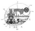
本願は図1から図3に示すように、該弁部材は調理器具の蓋体10上に位置し、弁室20と、弁室20に設けられる弁棒21とを備え、外部と連通しながら弁口22を備える圧力弁であって、弁棒21は、弁口22を密封するシール端211と、シール端211に対向する駆動端212とを有し、弁棒21は、弁室20内を移動可能であり、弁室20の弁室壁は、弁棒21の駆動端212に対応して設けられる弾性変形可能な弾性壁24を含む圧力弁と、弁室20外に設けられたピストン柱60を含む駆動装置であって、弁口22を開閉するようにピストン柱60が弾性壁24を弾性変形させて弁棒21を移動させるように駆動するようにピストン柱60の移動方向の先端62が弾性壁24の外壁に対応して設けられる駆動装置と、を含む。In the present application, as shown in FIGS. 1 to 3, the valve member is located on the
本願の技術案により、圧力弁の弁室20の弁室壁が弁棒21の駆動端212に対応して設けられる弾性変形可能な弾性壁24を含むとともに、駆動装置におけるピストン柱60の先端62が弾性壁24の外壁に対応して設けられるように設置することにより、駆動源がピストン柱60を往復運動させるように駆動すると、ピストン柱60の先端62が弾性壁24を弾性変形させ、該弾性壁24の弾性変形が弁棒21の駆動端212に当接することができることによって、弁口22を開閉するように弁棒21を移動させるように駆動する。このように、該弁部材を炊飯器に適用する際に、弁口22が鍋体と連通し、ピストン柱60の移動を調節し、弁棒21により弁口22を封止するか否か、またはいつ弁口22を開閉するかを調節することにより、所望の調理効果を実現することができ、例えば、異なる圧力値で弁口22を開放して「突沸」現象を実現することができる。また、先にピストン柱60が弁棒21に大きな力を加えて、弁棒21が弁口22を強固に封止してから、ピストン柱60の弁棒21への圧力を低減することで、弁口22を開ける目的を実現してもよい。即ち、本願の弁部材は、多様な方式で弁口22の開閉を実現できる。According to the technical proposal of the present application, the valve chamber wall of the valve chamber 20 of the pressure valve includes an elastically deformable
図3に示すように、ピストン柱60には、鉛直なピストン柱60の移動方向に延びた位置規制突起63が設けられ、ブラケット30aにはピストン柱60を収容する位置規制貫通溝301が設けられ、位置規制貫通溝301の軸方向はピストン柱60の移動方向と一致している。このように、位置規制リブは、ピストン柱60が位置規制貫通溝301内で回転するのを規制できる。もちろん、本願の他の実施例では、ピストン柱60が角構造を有するように設けてもよく、ピストン柱60が回転するのも防止できる。As shown in FIG. 3, the
ピストン柱60は、図3および図4に示すように、シフトレバー3の一端との間に第1支持板31と第2支持板32とが間隔を隔てて設置され、前記第1支持板31と前記第2支持板32とには、第1長尺孔311と第2長尺孔321とが対応して設けられており、前記第1長尺孔31の長さは前記第2長尺孔321の長さよりも長く、前記ピストン柱60は、両側に向かって第1突起201と第2突起202が突設されており、前記第1突起201と第2突起202は、前記第1長尺孔311と第2長尺孔321に対応して嵌合する。As shown in FIGS. 3 and 4, the
装着時に、前記第1突起201と第2突起202がともに前記第1長尺孔311と第2長尺孔321との間に位置するとき、前記ピストン柱60が回転すると、前記第1突起201と第2突起202が前記第1長尺孔311と第2長尺孔321とに同時に入り込むことができる。When the
具体的には、本実施例では、前記ピストン柱60は「T」形状の構造であり、前記「T」形状の尾部が前記第1突起201と第2突起202である。装着後に、前記第1突起201と前記第2突起202がそれぞれ前記第1長尺孔311と第2長尺孔321内に設けられることで、前記シフトレバー3が移動時に前記ピストン柱60を移動させるように駆動できることにより、前記調理器具の圧力弁の閾値を調整する目的を達成する。Specifically, in this embodiment, the
装着段階では、前記第1突起201が前記第1長尺孔311の一端から第1長尺孔311に入り込み、前記第2突起202が前記第1長尺孔311の他端から第2長尺孔321に入り込み、前記第1突起201と第2突起202が前記第1長尺孔311と第2長尺孔321にそれぞれ楽に配置されることで、前記ピストン柱60の装着難易度が低下し、生産性が向上する。同時に、本実施例では、前記第2長尺孔321が短いため、前記第2突起202は、前記第2長尺孔321での移動空間が限られ、制限作用が生じることで、前記調理器具のピストン柱60の運転時の安定性が向上する。At the mounting stage, the
本願の一実施例では、前記第1突起201の長さは、前記第2突起202の長さよりも長い。本実施例では、第1突起201の長さは前記第2突起202の長さよりも長く、長い第1突起201が長い第1長尺孔311内を移動するときに第1長尺孔311から抜けにくくし、前記ピストン柱60の移動時により安定、確実にさせ、運転時の安定性がさらに向上する。In one embodiment of the present application, the length of the
続けて図4を参照し、前記第1支持板31と前記第2支持板32は、前記シフトレバー3の端部から離れ、接続板33によって接続される。Subsequently, referring to FIG. 4, the
本実施例では、前記第1支持板31と前記第2支持板32との間に接続板33を設けることで、前記第1支持板31と前記第2支持板32の構造をより強固にし、弾性変形や振動が生じにくくなり、前記ピストン柱の接続構造の運転時の安定性がさらに向上する。In this embodiment, by providing the
また、本願の一実施例では、前記接続板33には、退避切欠331が設けられている。本実施例では、前記接続板33に退避切欠331が設けられることで、着脱時に、前記退避切欠331を利用して前記第1突起201および第2突起202を前記第1長尺孔311および第2長尺孔321から出し入れすることができ、前記ピストン柱60の装着難易度がさらに低下し、生産性が向上する。Further, in one embodiment of the present application, the
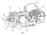
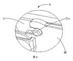
また、該弁部材は、図5〜図9に示すように、前記シフトレバー3が設けられているブラケット30aをさらに含み、該ブラケット30aは、幅方向における対向する両側にいずれも上方に延びた立板30が設けられ、2つの立板30に、対向する位置で対応して装着孔が設けられており、シフトレバー3が2つの立板の間に位置し、シフトレバー3の装着孔に対応する位置に装着孔に嵌合する回転軸21aが突設されることにより、シフトレバー3がブラケット30aの長手方向の両端で回転軸21aの回りを上下に揺動可能にする。ここで、立板30は、図9に示すように、シフトレバー3がブラケット30aの幅方向に揺動するのを規制するように、シフトレバー3との間の位置に位置規制リブ40が設けられている。Further, as shown in FIGS. 5 to 9, the valve member further includes a
具体的には、本実施例では、ブラケット30aの長手方向は図5における座標の左右方向であり、ブラケット30aの幅方向は図5における座標の前後方向である。立板30は、ブラケット30aの上面の前後方向の両側に突設され、ブラケット30aと一体的に設けられ、シフトレバー3は回転軸21aと装着孔との嵌合によって立板30に回動して設けられ、シフトレバー3の左右両端は回転軸21aの回りを上下に揺動することができる。図9に示すように、立板30とシフトレバー3との間に一定の隙間があり、立板30にシフトレバー3と対向する位置に位置規制リブ40が設けられている。このように、シフトレバー3が上下に揺動する過程で、位置規制リブ40がシフトレバー3の前後の両側面に当接することで、シフトレバー3の前後方向に揺動するスペースがほとんどなくなり、シフトレバー3の前後方向の揺動が効果的に回避される。Specifically, in this embodiment, the longitudinal direction of the
さらに、図9に示すように、位置規制リブ40は、弾性リブ41と止めリブ42とを含み、弾性リブ41の一端は立板30に接続され、弾性リブ41の他端は止めリブ42の上端に接続され、止めリブ42はシフトレバーに近接している。ここで、弾性リブ41は直線状でも、湾曲状でもよい。本実施例では、弾性リブ41は直線状で、下方に傾斜して設けられており、その弾性性能をより良くする。シフトレバー3が上下に揺動する過程で、シフトレバー3が絶えず止めリブ42に衝突すると、弾性リブ41が緩衝変形し、シフトレバー3の衝撃力を吸収して、立板30が破壊されないようにしつつ、シフトレバー3の揺動に有利である。Further, as shown in FIG. 9, the
好ましい実施例では、垂直方向において、止めリブ42の上端はシフトレバー3の重心よりも高く、止めリブ42の下端はシフトレバー3の底部まで下方に延びている。このような設置は、止めリブ42とシフトレバー3との十分な接触面を確保しつつ、シフトレバー3の上下揺動時の安定性をさらに高めることができる。In a preferred embodiment, in the vertical direction, the upper end of the
図9に示すように、位置規制リブ40は、シフトレバー3の底部に位置する接続リブ43を備え、ここで、接続リブ43の両端は、2つの止めリブ42の下端にそれぞれ接続されている。このように設置することで、位置規制リブ40の安定性がさらに補強され、シフトレバー3の上下揺動がより安定的に確保される。As shown in FIG. 9, the
具体的には、ブラケット30a、立板30、位置規制リブ40は一体的に設けられている。このようにすると、製作しやすく、ブラケット30aの全体的な強度が補強される。Specifically, the
図5に示すように、ブラケット30aの長手方向において、装着孔は立板30の一方側に位置し、位置規制リブ40は立板30の装着孔に対して他方側に位置する。シフトレバー3が上へ揺動する際に、回転軸21aはシフトレバー3の左右の揺動に対しても一定の固定作用を発揮し、装着孔と位置規制リブ40を立板30の左右方向の両側に設けることで、シフトレバー3が立板30の左右両側で受ける力を相対的に均一にして、シフトレバー3が上下に安定して揺動しやすくすることができる。As shown in FIG. 5, in the longitudinal direction of the
さらに、図5〜図7に示すように、前記シフトレバー3は、ブラケット30aに設けられるとともに、可動ギヤ41aに駆動接続されている。シフトレバー3を上下に揺動させるように駆動するように、可動ギヤ41aがブラケット30aにおけるシフトレバー3のセレーション端側に固定され、可動ギヤ41aは、シフトレバー3のセレーション端に噛合して設けられている。ここで、立板30はセレーション端に近い側に装着孔31aと連通する開口32aが設けられ、回転軸21aが開口32aを介して装着孔31aに装着される。Further, as shown in FIGS. 5 to 7, the
具体的に、本実施例では、ブラケット30aの左端には、モータ40aの駆動によって回動可能な可動ギヤ41aがさらに固定されているとともに、可動ギヤ41aは、シフトレバー3のセレーション端(すなわち、シフトレバーの左端)に噛合して設けられることで、シフトレバー3は、可動ギヤ41aの駆動によって、その左右両端が回転軸21a周りに上下に揺動可能となっている。ここで、シフトレバー3は鉛直方向(すなわち、上下方向)に360°回動するものではなく、一定の幅以内で揺動するものである。シフトレバー3を装着しやすくするために、立板30の左側に装着孔31aと連通する開口32aが開設されている。このように、この開口32aを介して回転軸21aを装着孔31aに装着することができる。また、可動ギヤ41aがシフトレバー3のセレーション端の左側に位置し、開口32aも立板30の左側に設けられており、可動ギヤ41aがシフトレバー3のセレーション端に噛合して設けられている。このため、シフトレバー3が左側に移動不可能となるため、可動ギヤ41aがシフトレバー3の回転軸21aを装着孔31aに安定的に位置規制することに相当し、回転軸21aが開口32aから抜けるのを不可能にする。このように設置することで、シフトレバー3が装着孔31a周りに安定して回動し、シフトレバー3の上下両端を安定して上下に揺動させることができる。Specifically, in this embodiment, a
図7に示すように、装着孔31aは開口32aに近接して設けられている。このように、開口32aと装着孔31aとの間の距離が長すぎることによる、立板30の強度の低下および回転軸21aの装着への不利な影響が回避される。As shown in FIG. 7, the mounting
また、開口32aと装着孔31aとの間にはラッパ形状に設けられた拡管部33aが設けられている。ここで、拡管部33aは装着孔31aに向かって収縮する傾向にある。このように、拡管部33aは左側に向かう方向に拡大する傾向にあり、開口32aでは相対的に大きく、回転軸21aを装着しやすい。Further, a
好ましい実施例では、開口32aの中心と装着孔31aの中心とは同じ水平位置にある。このように、拡管部33aは湾曲状ではなく、回転軸21aを装着しやすく、回転軸21aが装着孔31aに入り込むのをよりスムーズにする。In a preferred embodiment, the center of the opening 32a and the center of the mounting
さらに、装着孔31aと拡管部33aとの接続箇所は、回転軸に締まりばめになっている。拡管部33aと装着孔31aとの接続部の幅は、回転軸21aの直径よりも僅かに小さいので、回転軸21aが装着孔31aに入り込むと、装着孔31aからより一層抜けにくくなる。Further, the connection portion between the mounting
図7に示すように、拡管部33aの側壁は滑らかな曲面で設けられている。このように設置すると、回転軸21aの装着孔31aへの装着がよりスムーズになり、装着中の干渉を避ける。As shown in FIG. 7, the side wall of the
図6に示すように、回転軸21aは装着孔31aから突出する。回転軸21aの長さは立板30の厚さよりも長く、2つの回転軸21aを装着孔31aから前後方向にそれぞれ突出させるようにする。このように、回転軸21aが装着孔31aを回動する際により安定し、回転軸21aが装着孔31aから抜けにくくなる。As shown in FIG. 6, the
好ましくは、図5に示すように、装着孔31aは、シフトレバー3のセレーション端に近い。本実施例では、このように設置することで、シフトレバー3のセレーション端(すなわち、左端)と装着孔31aとの間の距離を、シフトレバー3の右端と装着孔31aとの間の距離よりも相対的に小さくすることで、モータ40aがシフトレバー3のセレーション端を上下方向に少しだけ移動させるように駆動した後で、シフトレバー3の左端が相対的に大きく移動するため、モータ40aによりシフトレバー3の右端をより良く制御するのを実現できる。Preferably, as shown in FIG. 5, the mounting
さらに、図10および図11を参照して、前記弁室20は、調圧弁カバー100によって形成され、前記圧力弁は上下方向に延びる適合するガイドリブ410およびガイド溝420を含むガイド機構をさらに含み、ガイドリブ410は調圧弁カバー100に設けられ、ガイド溝420は弁棒21に設けられ、または、ガイドリブ410は弁棒21に設けられ、ガイド溝420は調圧弁カバー100に設けられる。Further, with reference to FIGS. 10 and 11, the valve chamber 20 is formed by a pressure regulating
ガイドリブ410およびガイド溝420は上下方向に延び、ガイドリブ410とガイド溝420が嵌合して、弁棒21が調圧弁カバー100に対して上下方向に移動することを規制することにより、弁棒21の水平面内での回転を回避すると同時に、弁棒21が水平面に対して傾斜することを回避して、弁棒21が調圧弁の開閉を正確に制御して、調圧弁の信頼性を向上させた。The
具体的には、調理器具では、弁口22はブラケット30aの内蓋板600に設けられ、調圧弁は弁口22に設けられ、調理器具の内部圧力を調節するために用いられる。調理器具には制御パネルに制御される圧力駆動機構が設けられており、設定されたプログラムに従って圧力駆動機構によって調圧弁に一定の圧力を加え、さらに調理器具内部に異なる内部圧力を形成する。調圧弁が閉状態にあるとき、調理器具の内部圧力は外部の大気圧力よりも大きく、その中の水の沸点を高め、食材をより効率的に調理する。調理器具の内部気体の調圧弁に対する圧力が圧力駆動機構に加えられる圧力を超えると、調圧弁が開き、内部圧力が急速に低下し、安全性が確保され、内外圧力差が大きすぎて爆発することが回避される一方、水が急に沸騰するに伴って食材を転がして調理をより均一にし、調理効果を改善した。Specifically, in a cooking utensil, the
ここで、調圧弁カバー100は調理器具の弁口22の上方に設けられており、調圧弁カバー100の蓋体には圧力抜き孔が設けられており、調圧弁が開くと圧力抜き孔からガスが排出される。圧力抜き孔は、調圧弁カバーの側面に設けられてもよい。調圧弁カバー100の上面には、退避孔120がさらに設けられており、調理器具の圧力駆動機構が、退避孔120を貫通して調圧弁カバー100の内部に設けられた弁棒21の上面に当接することで、調理器具の内部圧力を制御すると同時に、退避孔120を介して組立中に観察しやすくなり、組立効率が向上する。調理器具の内部気体の調圧弁に対する圧力が圧力駆動機構による調圧弁押え棒への圧力よりも大きくなると、調圧弁は開き、内部の高圧蒸気が弁口22から噴出し、内部圧力を低下させる。調理器具の内部気体の調圧弁に対する圧力が、圧力駆動機構の調圧弁押え棒への圧力よりも小さくなると、調圧弁は閉じる。Here, the pressure regulating
さらに、少なくとも2つのガイドリブ410は調圧弁カバー100に均一に分布し、少なくとも2つのガイド溝420は弁棒21に均一に分布し、または、少なくとも2つのガイドリブが調圧弁押え棒に均一に分布し、少なくとも2つのガイド溝が調圧弁カバーに均一に分布している。本実施例では、図12に示すように、調圧弁カバー100と弁棒21の周縁に沿って3組のガイドリブ410とガイド溝420が均一に設けられており、弁棒21の上面に当接する圧力駆動機構が圧力を加えると、均一に分布したガイドリブ410とガイド溝420が弁棒21の上下方向の移動のバランスを確保し、弁棒21の水平面内での回転と水平面に対する傾きをより良く回避している。Further, at least two
本実施例では、図12および図13に示すように、ガイドリブ410の装着端411は縮径して設けられている。ここで、ガイドリブ410の装着端411は、ガイドリブ410とガイド溝420との組立過程で最初にガイド溝420に入った端である。本実施例では、装着端411がガイドリブ410の下端であり、ガイド溝420が調圧弁カバー100に設けられ、ガイドリブ410が弁棒21に設けられていると、装着端411がガイドリブ410の上端である。縮径して設けられた装着端411は、ガイドリブ410とガイド溝420との組立過程でガイド作用を発揮し、組立難度を低減する。また、本実施例では、装着端411がガイドリブ410の下方に位置し、調理器具内で発生した気泡がガイドリブ410に当たったときに、縮径して設けられた下端がより尖っており、より効率的に気泡を突き破るのに有利である。In this embodiment, as shown in FIGS. 12 and 13, the mounting
さらに、図13に示すように、装着端411のガイド溝420に近い側はガイド溝420の延在方向と一致し、装着端411のガイド溝420から遠い側はガイド溝420に近い方向に縮径し、弁棒21が調圧弁カバー100に対して上下動するとき、ガイドリブ410のガイド溝420に近い側は常に上下方向に延びる。よって、ガイドリブ410がガイド溝420で傾くことによる弁棒21の傾きは回避される。Further, as shown in FIG. 13, the side of the mounting
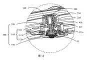
本実施例では、図14に示すように、ガイド溝420の溝口421が拡径して設けられており、調圧弁の組立過程でガイド作用を発揮し、ガイドリブ410をガイド溝420に収容しやすくして組立難度を低減している。In this embodiment, as shown in FIG. 14, the
本実施例では、図11に示すように、ガイドリブ410の下端は、ガイド溝420を超えて設けられている。調理器具内部の水が沸騰して発生した気泡がガイドリブ410の突出部分に浮上すると、ガイドリブ410の下端に突き破られて破泡作用を発揮し、食物の溢れを低減する。なお、ガイドリブ410が弁棒21に設けられている場合、ガイド溝420が調圧弁カバーに設けられ、ガイドリブ410も弁棒21の下端に対して突出するとともに、ガイド溝420を超えてもよい。In this embodiment, as shown in FIG. 11, the lower end of the
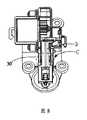
本願の一実施例では、図11に示すように、圧力弁の弁棒21は、調圧弁カバー100の内部に設けられた調圧弁体300と、下方に調圧弁体300が上下動して接続されることで、調理器具の調圧孔の開閉を制御する調圧弁押え棒200とをさらに含む。前記ガイドリブ410またはガイド溝420は、前記調圧弁押え棒200に設けられている。In one embodiment of the present application, as shown in FIG. 11, the
調圧弁体300には多様な設置方式がある。本実施例では、調圧弁体300は、調圧ばね座310と、ばね320と、弾性パッド330と、を含む。調圧ばね座310は、ベース311aと、ベース311aから上方に突出する調圧ばねロッド312とを含み、弁棒21の下方に設けられている。ばね320は調圧ばねロッド312に外装され、ばね320の上端は弁棒21に接続され、ばね320の下端はベース311aに接続される。弾性パッド330は、調圧ばね座のベース311aの下方に接続されている。具体的には、調圧弁押え棒200は、下方に延びた外側壁210を含み、外側壁210の内側に位置規制壁220が設けられている。The pressure regulating
本実施例では、弾性パッド330の上側外縁に接続溝331aが設けられ、ベース311aの下側に接続辺313aが設けられ、接続辺313aが接続溝331aに係止されて弾性パッド330を調圧ばね座310の下端に固定する。弾性パッド330はシリコンゴム製でもよく、シリコンゴムは良好な耐高温性と弾性を有する。弾性パッド330は、上下方向の縦断面に沿って上が広く下が狭く設けられており、弁口22の孔径によりよく嵌合して、調圧弁の密閉性を高め、気体漏れを防止する。In this embodiment, the connecting
本願では、弁部材を含む調理器具がさらに提案されている。該弁部材の具体的な構造について、上記の実施例を参照する。本調理器具は、上記の実施例の全ての技術案を採用しているので、少なくとも上記の実施例の技術案によりもたらすすべての有益な効果を有する。ここでは説明を省略する。In the present application, cooking utensils including valve members are further proposed. For the specific structure of the valve member, refer to the above embodiment. Since this cooking utensil adopts all the technical proposals of the above-described embodiment, it has at least all the beneficial effects brought about by the technical proposal of the above-mentioned embodiment. The description is omitted here.
ここで、調理器具は炊飯器、電気圧力鍋などでもよい。Here, the cooking utensil may be a rice cooker, an electric pressure cooker, or the like.
以上は本願の好適な実施例に過ぎず、これにより本願の特許請求の範囲を制限するものではなく、本願の出願思想を基に、本願の明細書及び図面の内容を利用してなされた等価構造変換、あるいは直接/間接的に他の関連技術分野に適用されるものは本願の特許保護範囲に含まれるべきである。The above is merely a preferred embodiment of the present application, which does not limit the scope of claims of the present application, and is equivalent to that made by utilizing the contents of the specification and drawings of the present application based on the application concept of the present application. Structural transformations, or those that apply directly / indirectly to other related technical fields, should be included in the claims of the present application.
10…蓋体、20…弁室、21…弁棒、22…弁口、60…ピストン柱、3…シフトレバー、40a…モータ、30a…ブラケット、211…シール端、212…駆動端、24…弾性壁、41a…可動ギヤ、201…第1突起、202…第2突起、63…位置規制突起、301…位置規制貫通溝、31…第1支持板、32…第2支持板、311…第1長尺孔、321…第2長尺孔、33…接続板、331…退避切欠、21a…回転軸、30…立板、31a…装着孔、32a…開口、33a…拡管部、40…位置規制リブ、41…弾性リブ、42…止めリブ、43…接続リブ、600…内蓋板、100…調圧弁カバー、200…調圧弁押え棒、300…調圧弁体、310…調圧ばね座、320…ばね、330…弾性パッド、312…調圧ばねロッド、311a…ベース、313a…接続辺、210…外側壁、220…位置規制壁、410…ガイドリブ、420…ガイド溝、411…装着端、331a…接続溝、120…退避孔、421…溝口。10 ... lid, 20 ... valve chamber, 21 ... valve rod, 22 ... valve opening, 60 ... piston column, 3 ... shift lever, 40a ... motor, 30a ... bracket, 211 ... seal end, 212 ... drive end, 24 ... Elastic wall, 41a ... Movable gear, 201 ... 1st protrusion, 202 ... 2nd protrusion, 63 ... Position regulation protrusion, 301 ... Position regulation through groove, 31 ... 1st support plate, 32 ... Second support plate, 311 ... 1 long hole, 321 ... second long hole, 33 ... connection plate, 331 ... retract notch, 21a ... rotating shaft, 30 ... standing plate, 31a ... mounting hole, 32a ... opening, 33a ... tube expansion part, 40 ... position Regulatory ribs, 41 ... elastic ribs, 42 ... stop ribs, 43 ... connection ribs, 600 ... inner lid plate, 100 ... pressure regulating valve cover, 200 ... pressure regulating valve retainer rod, 300 ... pressure regulating valve body, 310 ... pressure regulating spring seat, 320 ... Spring, 330 ... Elastic pad, 312 ... Pressure regulating spring rod, 311a ... Base, 313a ... Connection side, 210 ... Outer wall, 220 ... Position regulation wall, 410 ... Guide rib, 420 ... Guide groove, 411 ... Mounting end, 331a ... connection groove, 120 ... evacuation hole, 421 ... groove mouth.
Claims (19)
Translated fromJapanese弁室外に設けられ、ピストン柱を含む駆動装置であって、前記弁口を開閉するように前記ピストン柱が前記弾性壁を弾性変形させて前記弁棒を移動させるように駆動するように前記ピストン柱の移動方向の先端が前記弾性壁の外壁に対応して設けられる駆動装置と、を含み、
前記ピストン柱は、シフトレバーに接続され、
前記シフトレバーの一端に第1支持板と第2支持板とが間隔を隔てて設けられ、前記第1支持板と前記第2支持板とには、第1長尺孔と第2長尺孔とが対応して設けられており、前記第1長尺孔の長さは前記第2長尺孔の長さよりも長く、
前記ピストン柱は、両側に向かって第1突起と第2突起とが突設されており、前記第1突起と前記第2突起とは、前記第1長尺孔と前記第2長尺孔とに対応して嵌合することを特徴とする弁部材。A pressure valve having a valve chamber and a valve rod provided in the valve chamber, and having a valve port while communicating with the outside. The valve bar has a seal end for sealing the valve port and a seal end at the seal end. It has an opposing drive end, the valve stem is movable in the valve chamber, and the valve chamber wall of the valve chamber is an elastically deformable elastic wall provided corresponding to the drive end of the valve stem. With pressure valves, including
A drive device provided outside the valve chamber and including a piston column, the piston is driven so that the piston column elastically deforms the elastic wall and moves the valve rod so as to open and close the valve opening.see containing and a driving device arranged moving direction of the tip of the pillars corresponds to the outer wall of the elasticwall,
The piston column is connected to a shift lever and
A first support plate and a second support plate are provided at one end of the shift lever at intervals, and the first support plate and the second support plate have a first long hole and a second long hole. The length of the first long hole is longer than the length of the second long hole.
The piston column has a first protrusion and a second protrusion projecting toward both sides, and the first protrusion and the second protrusion are the first long hole and the second long hole. A valve member characterizedin that it isfitted in accordance with the above.
前記ブラケットは、幅方向における対向する両側にいずれも上方に延びた立板が設けられ、2つの前記立板は対向する位置に装着孔が対応して設けられており、
前記シフトレバーが2つの前記立板の間に位置し、前記シフトレバーの前記装着孔に対応する位置に前記装着孔に嵌合する回転軸が突設されることにより、前記シフトレバーの前記ブラケットの長手方向の両端を前記回転軸周りに上下に揺動可能にし、
前記立板は、前記シフトレバーが前記ブラケットの幅方向に揺動するのを規制するように、前記シフトレバーとの間の位置に位置規制リブが設けられていることを特徴とする請求項1に記載の弁部材。Before Symbol shift lever is provided in the bracket,
The bracket is provided with standing plates extending upward on both sides facing each other in the width direction, and the two standing plates are provided with mounting holes corresponding to the facing positions.
The shift lever is located between the two standing plates, and a rotation shaft that fits into the mounting hole is projected at a position corresponding to the mounting hole of the shift lever, whereby the length of the bracket of the shift lever is extended. Both ends in the direction can be swung up and down around the rotation axis.
Claim 1 is characterized in that the standing plate is provided with a position regulating rib at a position between the shift lever and the shift lever so as to restrict the shift lever from swinging in the width direction of the bracket. The valve member described in.
前記ブラケットは、幅方向における対向する両側にいずれも上方に延びた立板が設けられ、2つの前記立板は対向する位置に装着孔が対応して設けられており、
前記シフトレバーが2つの前記立板の間に位置し、前記シフトレバーの前記装着孔に対応する位置に前記装着孔に適合する回転軸が突設されているとともに、前記シフトレバーの前記ブラケットの長手方向の一端が垂直方向にセレーション状に設けられており、前記回転軸が前記装着孔に位置すると、前記シフトレバーの前記ブラケットの長手方向の両端が前記回転軸周りに上下に揺動可能であり、
前記可動ギヤは前記ブラケットの長手方向における前記シフトレバーのセレーション端に近い側に固定され、前記可動ギヤは、前記セレーション端に噛合して設けられていることで、前記シフトレバーを上下に揺動させるように駆動し、
前記立板は前記セレーション端に近い側に前記装着孔と連通する開口が設けられ、前記回転軸が前記開口を介して前記装着孔に装着されることを特徴とする請求項1に記載の弁部材。Before SL shift lever with is provided to the bracket, it is drivingly connected to the movable gear,
The bracket is provided with standing plates extending upward on both sides facing each other in the width direction, and the two standing plates are provided with mounting holes corresponding to the facing positions.
The shift lever is located between the two standing plates, a rotation shaft suitable for the mounting hole is projected at a position corresponding to the mounting hole of the shift lever, and a longitudinal direction of the bracket of the shift lever is provided. When one end of the shift lever is provided in a serration shape in the vertical direction and the rotation axis is located in the mounting hole, both ends of the bracket in the longitudinal direction of the shift lever can swing up and down around the rotation axis.
The movable gear is fixed to the side close to the serration end of the shift lever in the longitudinal direction of the bracket, and the movable gear is provided so as to mesh with the serration end to swing the shift lever up and down. Drive to let
The valve according to claim 1, wherein the standing plate is provided with an opening communicating with the mounting hole on a side close to the serration end, and the rotating shaft is mounted in the mounting hole through the opening. Element.
弁室外に設けられ、ピストン柱を含む駆動装置であって、前記弁口を開閉するように前記ピストン柱が前記弾性壁を弾性変形させて前記弁棒を移動させるように駆動するように前記ピストン柱の移動方向の先端が前記弾性壁の外壁に対応して設けられる駆動装置と、を含み、
前記弁室は、調圧弁カバーによって形成され、前記圧力弁は、
上下方向に延びる適合するガイドリブおよびガイド溝を含むガイド機構をさらに含み、前記ガイドリブは前記調圧弁カバーに設けられ、前記ガイド溝は前記弁棒に設けられ、または、前記ガイドリブは前記弁棒に設けられ、前記ガイド溝は前記調圧弁カバーに設けられていることを特徴とする弁部材。A pressure valve having a valve chamber and a valve rod provided in the valve chamber, and having a valve port while communicating with the outside. The valve bar has a seal end for sealing the valve port and a seal end at the seal end. It has an opposing drive end, the valve stem is movable in the valve chamber, and the valve chamber wall of the valve chamber is an elastically deformable elastic wall provided corresponding to the drive end of the valve stem. With pressure valves, including
A drive device provided outside the valve chamber and including a piston column, the piston is driven so that the piston column elastically deforms the elastic wall and moves the valve rod so as to open and close the valve opening. Including a drive device in which the tip of the column in the moving direction is provided corresponding to the outer wall of the elastic wall.
The valve chamber is formed by a pressure regulating valve cover, and the pressure valve is
Further including a guide mechanism including a compatible guide rib and a guide groove extending in the vertical direction, the guide rib is provided on the pressure regulating valve cover, the guide groove is provided on the valve stem, or the guide rib is provided on the valve stem. is, the guide grooves areyou characterized in that provided in the pressure regulating valve covervalve member.
少なくとも2つの前記ガイドリブは前記弁棒に均一に分布し、少なくとも2つの前記ガイド溝は前記調圧弁カバーに均一に分布していることを特徴とする請求項14に記載の弁部材。At least two guide ribs are uniformly distributed on the pressure regulating valve cover, and at least two guide grooves are uniformly distributed on the valve stem, or
The valve member according to claim14 , wherein at least two guide ribs are uniformly distributed on the valve stem, and at least two guide grooves are uniformly distributed on the pressure regulating valve cover.
Applications Claiming Priority (11)
| Application Number | Priority Date | Filing Date | Title |
|---|---|---|---|
| CN201611271164.3ACN108261060A (en) | 2016-12-30 | 2016-12-30 | Pressure regulator valve and cooking apparatus |
| CN201621493694.8 | 2016-12-30 | ||
| CN201621489287.X | 2016-12-30 | ||
| CN201621493694.8UCN206700006U (en) | 2016-12-30 | 2016-12-30 | Piston boit attachment structure and cooking apparatus |
| CN201621493691.4UCN206809158U (en) | 2016-12-30 | 2016-12-30 | Cover assembly and electric cooker |
| CN201621489287.XUCN206687585U (en) | 2016-12-30 | 2016-12-30 | Valve member and the electric cooker with valve member |
| CN201621489476.7UCN206809157U (en) | 2016-12-30 | 2016-12-30 | Cover assembly and electric cooker |
| CN201611271164.3 | 2016-12-30 | ||
| CN201621493691.4 | 2016-12-30 | ||
| CN201621489476.7 | 2016-12-30 | ||
| PCT/CN2017/114827WO2018121199A1 (en) | 2016-12-30 | 2017-12-06 | Valve assembly and cooking device |
Publications (2)
| Publication Number | Publication Date |
|---|---|
| JP2020501729A JP2020501729A (en) | 2020-01-23 |
| JP6811326B2true JP6811326B2 (en) | 2021-01-13 |
Family
ID=62707862
Family Applications (1)
| Application Number | Title | Priority Date | Filing Date |
|---|---|---|---|
| JP2019532748AActiveJP6811326B2 (en) | 2016-12-30 | 2017-12-06 | Valve members and cookware |
Country Status (3)
| Country | Link |
|---|---|
| JP (1) | JP6811326B2 (en) |
| KR (1) | KR102195621B1 (en) |
| WO (1) | WO2018121199A1 (en) |
Families Citing this family (16)
| Publication number | Priority date | Publication date | Assignee | Title |
|---|---|---|---|---|
| WO2019032876A1 (en) | 2017-08-09 | 2019-02-14 | Sharkninja Operating Llc | Cooking device and components thereof |
| USD914447S1 (en) | 2018-06-19 | 2021-03-30 | Sharkninja Operating Llc | Air diffuser |
| USD883014S1 (en) | 2018-08-09 | 2020-05-05 | Sharkninja Operating Llc | Food preparation device |
| USD883015S1 (en) | 2018-08-09 | 2020-05-05 | Sharkninja Operating Llc | Food preparation device and parts thereof |
| USD903413S1 (en) | 2018-08-09 | 2020-12-01 | Sharkninja Operating Llc | Cooking basket |
| USD934027S1 (en) | 2018-08-09 | 2021-10-26 | Sharkninja Operating Llc | Reversible cooking rack |
| CN110960067B (en)* | 2018-09-30 | 2021-06-18 | 佛山市顺德区美的电热电器制造有限公司 | Cooking appliance and control method thereof |
| CN109303493B (en)* | 2018-11-20 | 2024-04-26 | 中山市掌声电器有限公司 | Inner pot heating device with valve controlled by gears and pulling rods |
| CN111374539B (en)* | 2018-12-28 | 2025-03-04 | 浙江绍兴苏泊尔生活电器有限公司 | Cooking utensils |
| US11051654B2 (en) | 2019-02-25 | 2021-07-06 | Sharkninja Operating Llc | Cooking device and components thereof |
| WO2020176477A1 (en) | 2019-02-25 | 2020-09-03 | Sharkninja Operating Llc | Cooking system with guard |
| USD918654S1 (en) | 2019-06-06 | 2021-05-11 | Sharkninja Operating Llc | Grill plate |
| USD982375S1 (en) | 2019-06-06 | 2023-04-04 | Sharkninja Operating Llc | Food preparation device |
| FR3097732B1 (en)* | 2019-06-27 | 2022-12-16 | Seb Sa | Cooking appliance for cooking food with or without pressure. |
| US11678765B2 (en) | 2020-03-30 | 2023-06-20 | Sharkninja Operating Llc | Cooking device and components thereof |
| CN112167970B (en)* | 2020-08-07 | 2025-04-01 | 广东格兰仕集团有限公司 | A pressure cooker |
Family Cites Families (8)
| Publication number | Priority date | Publication date | Assignee | Title |
|---|---|---|---|---|
| JPH0232121U (en)* | 1988-08-24 | 1990-02-28 | ||
| JP4018124B2 (en)* | 2001-10-05 | 2007-12-05 | 象印マホービン株式会社 | Pressure cooker |
| ES2383406B1 (en)* | 2009-09-07 | 2013-05-03 | Fagor, S.Coop | SAFETY DEVICE FOR A PRESSURE COOKER |
| WO2016159796A1 (en)* | 2015-03-31 | 2016-10-06 | Admi Spółka Z Ograniczoną Odpowiedzialnością | Universal venting system for vacuum containers |
| JP2016209416A (en)* | 2015-05-12 | 2016-12-15 | 象印マホービン株式会社 | Cooker |
| CN106551618A (en)* | 2015-09-25 | 2017-04-05 | 佛山市顺德区美的电热电器制造有限公司 | Cover assembly and cooking apparatus |
| CN205338626U (en)* | 2016-01-13 | 2016-06-29 | 武汉苏泊尔炊具有限公司 | Relief valve and pressure cooker for pressure cooker |
| CN206687585U (en)* | 2016-12-30 | 2017-12-01 | 佛山市顺德区美的电热电器制造有限公司 | Valve member and the electric cooker with valve member |
- 2017
- 2017-12-06JPJP2019532748Apatent/JP6811326B2/enactiveActive
- 2017-12-06WOPCT/CN2017/114827patent/WO2018121199A1/ennot_activeCeased
- 2017-12-06KRKR1020197015446Apatent/KR102195621B1/enactiveActive
Also Published As
| Publication number | Publication date |
|---|---|
| JP2020501729A (en) | 2020-01-23 |
| KR102195621B1 (en) | 2020-12-28 |
| KR20190077041A (en) | 2019-07-02 |
| WO2018121199A1 (en) | 2018-07-05 |
Similar Documents
| Publication | Publication Date | Title |
|---|---|---|
| JP6811326B2 (en) | Valve members and cookware | |
| JP6794549B2 (en) | Valve member and rice cooker equipped with it | |
| CN205322075U (en) | A pressure cooker that is used for pot cover of pressure cooker and has it | |
| JP2016510862A (en) | Valve plate and air pump having the same | |
| EP2682030A2 (en) | Pot lid capable of preventing food from boiling over | |
| KR20160006698A (en) | A rice cooker | |
| CN105466099B (en) | Refrigerator | |
| JP2013220173A (en) | Container with lid | |
| JP2015521264A (en) | Instant response float operation type steam vent valve | |
| CN105559619B (en) | Exhaust valve component and electric cooker with it | |
| CN110296258B (en) | Electronic expansion valve | |
| KR101359383B1 (en) | damper apparatus for regulating damping force according to rotating angle and electric cooker with the same | |
| CN209610873U (en) | Pressure relief structure and electric heating water cup | |
| EP2455644A1 (en) | Magnetic control valve | |
| CN105466122B (en) | double door refrigerator | |
| CN109984580B (en) | Electric pressure cooker | |
| US10859080B2 (en) | Valve head structure for diaphragm pump and diaphragm pump having same | |
| CN204445483U (en) | Steam valve and cooking apparatus | |
| CN205322077U (en) | Upper cover subassembly of culinary art device and have its culinary art device | |
| CN106037501A (en) | Steam valve assembly and cooking apparatus provided with the same | |
| CN204410596U (en) | Electric cooker steam valve | |
| CN109984576A (en) | Cooking apparatus and its control method | |
| JP2018531050A6 (en) | Steam valves, container covers and liquid heating containers | |
| JP2018531050A (en) | Steam valves, container covers and liquid heating containers | |
| CN203477498U (en) | Overflow stop valve |
Legal Events
| Date | Code | Title | Description |
|---|---|---|---|
| A621 | Written request for application examination | Free format text:JAPANESE INTERMEDIATE CODE: A621 Effective date:20190617 | |
| A977 | Report on retrieval | Free format text:JAPANESE INTERMEDIATE CODE: A971007 Effective date:20200520 | |
| A131 | Notification of reasons for refusal | Free format text:JAPANESE INTERMEDIATE CODE: A131 Effective date:20200623 | |
| A521 | Request for written amendment filed | Free format text:JAPANESE INTERMEDIATE CODE: A523 Effective date:20200909 | |
| TRDD | Decision of grant or rejection written | ||
| A01 | Written decision to grant a patent or to grant a registration (utility model) | Free format text:JAPANESE INTERMEDIATE CODE: A01 Effective date:20201208 | |
| A61 | First payment of annual fees (during grant procedure) | Free format text:JAPANESE INTERMEDIATE CODE: A61 Effective date:20201214 | |
| R150 | Certificate of patent or registration of utility model | Ref document number:6811326 Country of ref document:JP Free format text:JAPANESE INTERMEDIATE CODE: R150 | |
| R250 | Receipt of annual fees | Free format text:JAPANESE INTERMEDIATE CODE: R250 | |
| R250 | Receipt of annual fees | Free format text:JAPANESE INTERMEDIATE CODE: R250 |