JP6810011B2 - Fluid migration device and how to use it - Google Patents
Fluid migration device and how to use itDownload PDFInfo
- Publication number
- JP6810011B2 JP6810011B2JP2017200208AJP2017200208AJP6810011B2JP 6810011 B2JP6810011 B2JP 6810011B2JP 2017200208 AJP2017200208 AJP 2017200208AJP 2017200208 AJP2017200208 AJP 2017200208AJP 6810011 B2JP6810011 B2JP 6810011B2
- Authority
- JP
- Japan
- Prior art keywords
- fluid
- connector
- interface
- target
- syringe
- Prior art date
- Legal status (The legal status is an assumption and is not a legal conclusion. Google has not performed a legal analysis and makes no representation as to the accuracy of the status listed.)
- Active
Links
Images


Classifications
- A—HUMAN NECESSITIES
- A61—MEDICAL OR VETERINARY SCIENCE; HYGIENE
- A61J—CONTAINERS SPECIALLY ADAPTED FOR MEDICAL OR PHARMACEUTICAL PURPOSES; DEVICES OR METHODS SPECIALLY ADAPTED FOR BRINGING PHARMACEUTICAL PRODUCTS INTO PARTICULAR PHYSICAL OR ADMINISTERING FORMS; DEVICES FOR ADMINISTERING FOOD OR MEDICINES ORALLY; BABY COMFORTERS; DEVICES FOR RECEIVING SPITTLE
- A61J1/00—Containers specially adapted for medical or pharmaceutical purposes
- A61J1/14—Details; Accessories therefor
- A61J1/20—Arrangements for transferring or mixing fluids, e.g. from vial to syringe
- A61J1/2096—Combination of a vial and a syringe for transferring or mixing their contents
- A—HUMAN NECESSITIES
- A61—MEDICAL OR VETERINARY SCIENCE; HYGIENE
- A61J—CONTAINERS SPECIALLY ADAPTED FOR MEDICAL OR PHARMACEUTICAL PURPOSES; DEVICES OR METHODS SPECIALLY ADAPTED FOR BRINGING PHARMACEUTICAL PRODUCTS INTO PARTICULAR PHYSICAL OR ADMINISTERING FORMS; DEVICES FOR ADMINISTERING FOOD OR MEDICINES ORALLY; BABY COMFORTERS; DEVICES FOR RECEIVING SPITTLE
- A61J1/00—Containers specially adapted for medical or pharmaceutical purposes
- A61J1/05—Containers specially adapted for medical or pharmaceutical purposes for collecting, storing or administering blood, plasma or medical fluids ; Infusion or perfusion containers
- A61J1/10—Bag-type containers
- A—HUMAN NECESSITIES
- A61—MEDICAL OR VETERINARY SCIENCE; HYGIENE
- A61J—CONTAINERS SPECIALLY ADAPTED FOR MEDICAL OR PHARMACEUTICAL PURPOSES; DEVICES OR METHODS SPECIALLY ADAPTED FOR BRINGING PHARMACEUTICAL PRODUCTS INTO PARTICULAR PHYSICAL OR ADMINISTERING FORMS; DEVICES FOR ADMINISTERING FOOD OR MEDICINES ORALLY; BABY COMFORTERS; DEVICES FOR RECEIVING SPITTLE
- A61J1/00—Containers specially adapted for medical or pharmaceutical purposes
- A61J1/14—Details; Accessories therefor
- A61J1/20—Arrangements for transferring or mixing fluids, e.g. from vial to syringe
- A61J1/2003—Accessories used in combination with means for transfer or mixing of fluids, e.g. for activating fluid flow, separating fluids, filtering fluid or venting
- A61J1/2006—Piercing means
- A61J1/201—Piercing means having one piercing end
- A—HUMAN NECESSITIES
- A61—MEDICAL OR VETERINARY SCIENCE; HYGIENE
- A61J—CONTAINERS SPECIALLY ADAPTED FOR MEDICAL OR PHARMACEUTICAL PURPOSES; DEVICES OR METHODS SPECIALLY ADAPTED FOR BRINGING PHARMACEUTICAL PRODUCTS INTO PARTICULAR PHYSICAL OR ADMINISTERING FORMS; DEVICES FOR ADMINISTERING FOOD OR MEDICINES ORALLY; BABY COMFORTERS; DEVICES FOR RECEIVING SPITTLE
- A61J1/00—Containers specially adapted for medical or pharmaceutical purposes
- A61J1/14—Details; Accessories therefor
- A61J1/20—Arrangements for transferring or mixing fluids, e.g. from vial to syringe
- A61J1/2003—Accessories used in combination with means for transfer or mixing of fluids, e.g. for activating fluid flow, separating fluids, filtering fluid or venting
- A61J1/2048—Connecting means
- A61J1/2058—Connecting means having multiple connecting ports
- A61J1/2062—Connecting means having multiple connecting ports with directional valves
- A—HUMAN NECESSITIES
- A61—MEDICAL OR VETERINARY SCIENCE; HYGIENE
- A61J—CONTAINERS SPECIALLY ADAPTED FOR MEDICAL OR PHARMACEUTICAL PURPOSES; DEVICES OR METHODS SPECIALLY ADAPTED FOR BRINGING PHARMACEUTICAL PRODUCTS INTO PARTICULAR PHYSICAL OR ADMINISTERING FORMS; DEVICES FOR ADMINISTERING FOOD OR MEDICINES ORALLY; BABY COMFORTERS; DEVICES FOR RECEIVING SPITTLE
- A61J1/00—Containers specially adapted for medical or pharmaceutical purposes
- A61J1/14—Details; Accessories therefor
- A61J1/20—Arrangements for transferring or mixing fluids, e.g. from vial to syringe
- A61J1/2003—Accessories used in combination with means for transfer or mixing of fluids, e.g. for activating fluid flow, separating fluids, filtering fluid or venting
- A61J1/2068—Venting means
- A61J1/2075—Venting means for external venting
- A—HUMAN NECESSITIES
- A61—MEDICAL OR VETERINARY SCIENCE; HYGIENE
- A61J—CONTAINERS SPECIALLY ADAPTED FOR MEDICAL OR PHARMACEUTICAL PURPOSES; DEVICES OR METHODS SPECIALLY ADAPTED FOR BRINGING PHARMACEUTICAL PRODUCTS INTO PARTICULAR PHYSICAL OR ADMINISTERING FORMS; DEVICES FOR ADMINISTERING FOOD OR MEDICINES ORALLY; BABY COMFORTERS; DEVICES FOR RECEIVING SPITTLE
- A61J1/00—Containers specially adapted for medical or pharmaceutical purposes
- A61J1/14—Details; Accessories therefor
- A61J1/20—Arrangements for transferring or mixing fluids, e.g. from vial to syringe
- A61J1/2003—Accessories used in combination with means for transfer or mixing of fluids, e.g. for activating fluid flow, separating fluids, filtering fluid or venting
- A61J1/2079—Filtering means
- A61J1/2082—Filtering means for gas filtration
- A—HUMAN NECESSITIES
- A61—MEDICAL OR VETERINARY SCIENCE; HYGIENE
- A61J—CONTAINERS SPECIALLY ADAPTED FOR MEDICAL OR PHARMACEUTICAL PURPOSES; DEVICES OR METHODS SPECIALLY ADAPTED FOR BRINGING PHARMACEUTICAL PRODUCTS INTO PARTICULAR PHYSICAL OR ADMINISTERING FORMS; DEVICES FOR ADMINISTERING FOOD OR MEDICINES ORALLY; BABY COMFORTERS; DEVICES FOR RECEIVING SPITTLE
- A61J1/00—Containers specially adapted for medical or pharmaceutical purposes
- A61J1/14—Details; Accessories therefor
- A61J1/20—Arrangements for transferring or mixing fluids, e.g. from vial to syringe
- A61J1/2089—Containers or vials which are to be joined to each other in order to mix their contents
- A—HUMAN NECESSITIES
- A61—MEDICAL OR VETERINARY SCIENCE; HYGIENE
- A61M—DEVICES FOR INTRODUCING MEDIA INTO, OR ONTO, THE BODY; DEVICES FOR TRANSDUCING BODY MEDIA OR FOR TAKING MEDIA FROM THE BODY; DEVICES FOR PRODUCING OR ENDING SLEEP OR STUPOR
- A61M39/00—Tubes, tube connectors, tube couplings, valves, access sites or the like, specially adapted for medical use
- A61M39/22—Valves or arrangement of valves
- B—PERFORMING OPERATIONS; TRANSPORTING
- B67—OPENING, CLOSING OR CLEANING BOTTLES, JARS OR SIMILAR CONTAINERS; LIQUID HANDLING
- B67D—DISPENSING, DELIVERING OR TRANSFERRING LIQUIDS, NOT OTHERWISE PROVIDED FOR
- B67D3/00—Apparatus or devices for controlling flow of liquids under gravity from storage containers for dispensing purposes
- B67D3/0003—Apparatus or devices for controlling flow of liquids under gravity from storage containers for dispensing purposes provided with automatic fluid control means
- A—HUMAN NECESSITIES
- A61—MEDICAL OR VETERINARY SCIENCE; HYGIENE
- A61J—CONTAINERS SPECIALLY ADAPTED FOR MEDICAL OR PHARMACEUTICAL PURPOSES; DEVICES OR METHODS SPECIALLY ADAPTED FOR BRINGING PHARMACEUTICAL PRODUCTS INTO PARTICULAR PHYSICAL OR ADMINISTERING FORMS; DEVICES FOR ADMINISTERING FOOD OR MEDICINES ORALLY; BABY COMFORTERS; DEVICES FOR RECEIVING SPITTLE
- A61J2200/00—General characteristics or adaptations
- A61J2200/70—Device provided with specific sensor or indicating means
- A61J2200/76—Device provided with specific sensor or indicating means for fluid level
- Y—GENERAL TAGGING OF NEW TECHNOLOGICAL DEVELOPMENTS; GENERAL TAGGING OF CROSS-SECTIONAL TECHNOLOGIES SPANNING OVER SEVERAL SECTIONS OF THE IPC; TECHNICAL SUBJECTS COVERED BY FORMER USPC CROSS-REFERENCE ART COLLECTIONS [XRACs] AND DIGESTS
- Y10—TECHNICAL SUBJECTS COVERED BY FORMER USPC
- Y10S—TECHNICAL SUBJECTS COVERED BY FORMER USPC CROSS-REFERENCE ART COLLECTIONS [XRACs] AND DIGESTS
- Y10S604/00—Surgery
- Y10S604/905—Aseptic connectors or couplings, e.g. frangible, piercable
- Y—GENERAL TAGGING OF NEW TECHNOLOGICAL DEVELOPMENTS; GENERAL TAGGING OF CROSS-SECTIONAL TECHNOLOGIES SPANNING OVER SEVERAL SECTIONS OF THE IPC; TECHNICAL SUBJECTS COVERED BY FORMER USPC CROSS-REFERENCE ART COLLECTIONS [XRACs] AND DIGESTS
- Y10—TECHNICAL SUBJECTS COVERED BY FORMER USPC
- Y10T—TECHNICAL SUBJECTS COVERED BY FORMER US CLASSIFICATION
- Y10T29/00—Metal working
- Y10T29/49—Method of mechanical manufacture
- Y10T29/49826—Assembling or joining
Landscapes
- Health & Medical Sciences (AREA)
- Veterinary Medicine (AREA)
- Life Sciences & Earth Sciences (AREA)
- Animal Behavior & Ethology (AREA)
- General Health & Medical Sciences (AREA)
- Public Health (AREA)
- Pharmacology & Pharmacy (AREA)
- Fluid Mechanics (AREA)
- Physics & Mathematics (AREA)
- Engineering & Computer Science (AREA)
- Hematology (AREA)
- Heart & Thoracic Surgery (AREA)
- Mechanical Engineering (AREA)
- Pulmonology (AREA)
- Anesthesiology (AREA)
- Biomedical Technology (AREA)
- Medical Preparation Storing Or Oral Administration Devices (AREA)
- Infusion, Injection, And Reservoir Apparatuses (AREA)
Description
Translated fromJapanese本出願は、35 U.S.C. § 119(e)の下で2009年7月29日付けで出願された流体移行装置と題された米国仮出願第61/229,701号ならびに2010年6月14日付けで出願された流体移行装置と題された米国仮出願第61/354,648号の権利を主張するものである。この参照によりこれら明細書に記載の内容すべてが本明細書に組み込まれ、かつこれら文献に開示されたすべてが本明細書の一部を構成する。 This application is filed under 35 USC § 119 (e) on July 29, 2009, US Provisional Application No. 61 / 229,701 entitled Fluid Transition Device and on June 14, 2010. It asserts the rights of 35 USC 61 / 354,648 entitled Fluid Transfer Device. By this reference, all the contents described in these specifications are incorporated in the present specification, and all disclosed in these documents form a part of the present specification.
本発明のいくつかの実施形態は、流体を移行するためのデバイスおよび方法におおむね関し、かつ特別には医療用流体を移行するためのデバイスおよび方法に関するものである。 Some embodiments of the present invention relate generally to devices and methods for transferring fluids, and in particular to devices and methods for transferring medical fluids.
ある状況下において、1つ以上の流体を容器同士の間で移動させることが望まれている。医療分野において、多くの場合、流体を正確な量で計量分配し、かつ潜在的に危険な流体を蓄積しかつ移行させることが望まれている。流動流体移行デバイスおよび方法は、医療分野において、高コスト、低効率、集中的な製剤ダメージ、および過剰な流体または上記の漏出などを含むさまざまな障害の影響を受ける。本明細書に開示されるいくつかの実施形態によれば、1つ以上のこれら欠点が解消される。 Under certain circumstances, it is desired to move one or more fluids between the containers. In the medical field, it is often desired to weigh and distribute fluids in accurate amounts and to accumulate and transfer potentially dangerous fluids. Fluid fluid transfer devices and methods are subject to a variety of obstacles in the medical field, including high cost, low efficiency, intensive formulation damage, and excess fluid or leaks described above. According to some embodiments disclosed herein, one or more of these drawbacks are eliminated.
本明細書に記載されたいくつかの実施形態は、正確な量の流体を供給容器からターゲット容器へ移行させるためのデバイスに関するものである。いくつかの実施形態において、流体は、まず供給容器からコネクタを介して中間測定容器(例えばシリンジ)へ移行させられる。正確に量が測定された流体は、続いて中間測定容器からターゲット容器まで移行可能となる。 Some embodiments described herein relate to devices for transferring the correct amount of fluid from a supply vessel to a target vessel. In some embodiments, the fluid is first transferred from the supply vessel to an intermediate measuring vessel (eg, a syringe) via a connector. The accurately measured fluid can then be transferred from the intermediate measurement vessel to the target vessel.
いくつかの実施形態において、医療用流体を異なる医療用流体用の容器同士の間で移行させるための、実質的に全体的に閉じられたシステムを提供するための方法およびデバイスに関するものであり、電子的に制御される流体分配システムに取り外し可能に取り付けることができる流体移行モジュールを含む。流体移行モジュールは、流体供給源および流体移行先容器にそれぞれ接続された第1および第2のインターフェースを備えることができる。第1および第2のインターフェースは、選択的に操作可能でありかつ閉鎖可能な開口を備えることができる。この開口は、閉鎖時に流体が開口を介して流体移行モジュール内に漏出することを実質的かつ全体的に防止できる。中間容器は、流体移行モジュールの一部またはそれに接続されていてもよい。流体移行モジュール内の1つ以上のバルブが、流体供給源から中間容器まで流体が移動できるようにするが中間容器から流体供給源へ流体が移動することをおおむね遮断することもでき、かつ中間容器から流体目的地まで流体を移動可能にするが流体目的地から中間容器まで流体が移動することをおおむね防止することができる。いくつかの実施形態において、流体移行モジュールは、電子的に制御される流体分配システムに取り付けることができ、かつ流体移行モジュールは、電子的に制御される流体分配システムが、流体移行モジュールの少なくとも一部が電子的に制御される流体分配システムに取り付けられていることを示すことが可能なように構成された相互作用部を含むことができる。いくつかの実施形態において、電子的に制御される流体分配システムは、相互作用ユーザーインターフェースを含むことができ、かつ医療用流体を正確な量で分配するよう構成可能である。 In some embodiments, it relates to a method and device for providing a substantially totally closed system for transferring a medical fluid between containers for different medical fluids. Includes a fluid transfer module that can be detachably attached to an electronically controlled fluid distribution system. The fluid transfer module may include first and second interfaces connected to the fluid source and the fluid transfer destination container, respectively. The first and second interfaces can include openings that are selectively operable and can be closed. This opening can substantially and totally prevent fluid from leaking into the fluid transfer module through the opening upon closure. The intermediate vessel may be part of a fluid transfer module or connected to it. One or more valves in the fluid transfer module allow the fluid to move from the fluid source to the intermediate vessel, but can also largely block the movement of fluid from the intermediate vessel to the fluid source, and the intermediate vessel. Although the fluid can be moved from the fluid destination to the fluid destination, it is possible to generally prevent the fluid from moving from the fluid destination to the intermediate container. In some embodiments, the fluid transfer module can be attached to an electronically controlled fluid distribution system, and the fluid transfer module is such that the electronically controlled fluid distribution system is at least one of the fluid transfer modules. It can include an interacting part configured to be able to indicate that the part is attached to an electronically controlled fluid distribution system. In some embodiments, the electronically controlled fluid distribution system can include an interacting user interface and can be configured to distribute the medical fluid in an accurate amount.
以下に本発明の特定の実施形態について図面を参照しながら説明する。これら図面は説明のためだけに提供されるものであり、かつ実施形態は図面に示された対象の事項に限定されるものではない。 A specific embodiment of the present invention will be described below with reference to the drawings. These drawings are provided for illustration purposes only, and embodiments are not limited to the subject matter shown in the drawings.
以下の詳細な説明は、本開示の特定の例示的な実施形態へ方向付けられている。この開示において、図面に参照符号が付与されているが、詳細な説明および図面にわたって同様の部分は同様の番号で示されるようになっている。 The following detailed description is directed to certain exemplary embodiments of the present disclosure. Although reference numerals have been added to the drawings in this disclosure, similar parts are designated by similar numbers throughout the detailed description and drawings.
多くの状況下において、流体は供給容器からターゲット容器へ移行させられる。多くの場合において、薬剤などの流体を正確な量でターゲット容器へ移行させることが望まれている。例えばいくつかの実施形態において、薬剤は、小型容器(vial)または他のコンテナに貯蔵可能であり、かつ正確な投与量の薬剤が抽出されてターゲットデバイスへ移行可能となっている。それにより所定の量の薬剤が患者へ供給される。いくつかの実施形態において、複数の供給容器からの流体を単一のターゲット容器へ向けて組み合わせるかもしくは合成させることができる。例えばいくつかの実施形態において、ターゲット容器内に薬剤の混合物を生成でき、あるいは集められた薬剤をターゲット容器内の希釈剤と混合させることができ、ターゲット容器内へ移行された流体の量を正確に測定することが望まれている。また、供給容器からターゲット容器へ移行された流体の量の正確な測定は、(例えば供給容器から必要量以上の流体が引き出された場合に)流体の無駄な量を低減させることができる。多くの場合において移行される流体は高価であるため、こうした無駄の削減が望まれている。 Under many circumstances, fluid is transferred from the supply vessel to the target vessel. In many cases, it is desired to transfer a fluid such as a drug to the target container in an accurate amount. For example, in some embodiments, the drug can be stored in a small container (vial) or other container, and the correct dose of the drug can be extracted and transferred to the target device. Thereby, a predetermined amount of the drug is supplied to the patient. In some embodiments, fluids from multiple supply vessels can be combined or combined towards a single target vessel. For example, in some embodiments, a mixture of drugs can be produced in the target container, or the collected drug can be mixed with a diluent in the target container to accurately determine the amount of fluid transferred into the target container. It is desired to measure. Also, accurate measurement of the amount of fluid transferred from the supply vessel to the target vessel can reduce the wasted amount of fluid (eg, when more fluid than required is drawn from the supply vessel). Since the fluid to be transferred is expensive in many cases, it is desired to reduce such waste.
本明細書に記載されたいくつかの実施形態は、流体を1つ以上の供給容器から1つ以上のターゲット容器へ正確な量で移動させるための流体移行デバイスを提供する。 Some embodiments described herein provide a fluid transfer device for transferring fluid from one or more supply vessels to one or more target vessels in an exact amount.
いくつかの実施形態において、密封されたシステムを使用して、供給容器からターゲット容器へ流体を移動させることが望ましい。ある実施形態において、流体を周囲空気へさらすことは、流体への異物の混入または流体との望ましくない反応を引き起こし得る。いくつかの薬剤(例えば化学治療薬剤)は健常者に対して有害となることがある。そのため、環境空気もしくは流体移行システムの外界に対して流体がさらされることを防止するかまたは低減させることが望まれている。いくつかの実施形態において、流体移行システムの外部領域への流体の暴露を防止するかまたは低減させる流体移行システムは、他の高価な装置(例えばクリーンルーム)を不必要とすることができ、それにより、流体を移動させるのに要する費用が低減される。 In some embodiments, it is desirable to use a sealed system to move the fluid from the supply vessel to the target vessel. In certain embodiments, exposing the fluid to ambient air can cause foreign matter to the fluid or unwanted reactions with the fluid. Some drugs (eg chemotherapeutic drugs) can be harmful to healthy individuals. Therefore, it is desired to prevent or reduce the exposure of the fluid to the ambient air or the outside world of the fluid transfer system. In some embodiments, the fluid transfer system that prevents or reduces the exposure of the fluid to the external regions of the fluid transfer system can eliminate the need for other expensive equipment (eg, clean rooms), thereby. , The cost required to move the fluid is reduced.
本明細書に開示されたいくつかの実施形態において、環境空気または流体移行システムの外側の領域に流体が接触することを防止し、あるいは接触する量を低減させるかまたは最小化させながら流体を移行させるための流体移行デバイスを提供する。 In some embodiments disclosed herein, the fluid is transferred while preventing or minimizing the amount of contact with the environmental air or the outer region of the fluid transfer system. Provide a fluid transfer device for making.
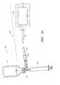
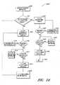
図1には、自動化された流体移行システム100を概略的に示す。このシステム100は、コントローラ104とメモリモジュール106とを封入するハウジング102を含んでもよい。またシステム100は、例えばハウジング102の外部に設けることができるユーザーインターフェース108を含んでもよい。ユーザーインターフェース108は、いくつかの場合においてハウジング102に一体化されていてもよい。ユーザーインターフェース108は、例えば、ディスプレイ、キーパッド、および/またはタッチスクリーンディスプレイを含んでもよい。ユーザーインターフェース108は、例えば移動させられる流体の量または移動させられる流体のタイプに関連して使用者から指示を受け取るよう構成されていてもよい。ユーザーインターフェースはまた、例えばエラーメッセージ、警告または(空の容器を交換することなどの)指示情報を使用者へ提供するよう構成されていてもよい。システム100は、コントローラ104と通信するバーコードスキャナ110を含むこともできる。図示された実施形態においては、コントローラ104およびメモリモジュール106は、ハウジング102内に収容されているが、他のさまざまな構造を用いることもできる。例えばコントローラ104は、ハウジング102の外部にあってもよく、例えば同時にユーザーインターフェース108を含む第2のハウジング内に含まれていてもよい。いくつかの実施形態において、システム100は、例えば端末または自動管理システムなどの遠隔発信源からの情報(例えば指示)を受け取るよう構成された連絡用インターフェース105を含むことができる。ある実施形態において、連絡用インターフェースは、遠隔発信源へ情報(例えば結果または警告)を送ることもできる。いくつかの実施形態において、システム100は、連絡用インターフェース105を含まずかつ
遠隔発信源と通信しないものとなっている。FIG. 1 schematically shows an automated
システム100は、多段移行ステーション112a〜cを含むことができる。図示された実施形態において、システム100は、3つの移行ステーション112a〜cを含むが、異なる数の移行ステーションを使用することができる。例えばある実施形態において、システムは、単一の移行ステーションを含んでいてもよい。他の実施形態においては、システムは、異なるタイプの流体の数、操作されるよう設計されたシステムおよび移行される流体の量に応じて2、4、5、6、7、8またはそれ以上の移行ステーションを含んでもよい。 The
各移行ステーション112a〜cは流体供給容器114a〜cを含むことが可能であり、当該流体供給容器は、例えばバッグ、ボトルまたはバットなどの薬剤用容器または他の適切な容器とすることができる。本明細書に記載の多くの実施形態が供給容器として小型容器を使用することが開示されているが、特に記載しない他の容器も使用できることを理解されたい。いくつかの実施形態において、使用者が移行のために選択可能なさまざまな流体を提供するよう、供給用域114a〜cのそれぞれが独自の流体を収容できる。他の実施形態において、2つ以上の供給容器114a〜cは同一の流体を含むこともできる。いくつかの実施形態において、供給容器114a〜cは、その中に収容される流体のタイプを識別するバーコードを含む。このバーコードは、供給容器114a〜cに収容された流体の識別情報をメモリモジュール106に蓄積できるように、スキャナ110によってスキャン可能である。いくつかの実施形態において、流体移行ステーション112a〜cは、供給容器114a〜cからターゲット容器116a〜cへ流体を正確な量で移行させるよう構成されている。ターゲット容器は例えばIVバッグであってもよい。特別には記載しないが、本明細書に記載のさまざまな実施形態において、IVバッグの代わりにさまざまなターゲット容器または到着容器(例えばシリンジ、ボトルまたは小型容器など)を使用することができることを理解されたい。ある実施形態において、正確な量の流体を計測するために、流体は供給容器114a〜114cから中間測定容器118a〜cへ移行可能である。中間測定容器118a〜cは例えばシリンジである。測定後に、流体は、中間測定容器118a〜cからターゲット容器116a〜cへ移行可能である。いくつかの実施形態において、1つ以上の移行ステーション112a〜cは、流体の経路を選択的に使用可能にするために互いに取り付けられるよう構成された1つ以上の一対の雄型および雌型流体コネクタを含むことができる。流体移行が完了したとき、コネクタは取り外されるかまたは解放される。いくつかの実施形態において、コネクタは、自動的に閉じるよう構成されていてもよい。各容器内の保持内部流体および残りの流体のモジュールを実質的に全体的にまたはそのすべてを全体的に保持すると同時に、流体モジュールを取り外すことができる。したがって実質的に全体的にまたは全体的に閉じられたシステムにおける移行を実施可能にし、それにより、分離後の流体モジュールからの、かつ流体供給源および分離後の流体目的地からの、液体または蒸気によって引き起こされる損傷の危険性が最小化される。 Each transition station 112a-c can include fluid supply containers 114a-c, which can be a drug container such as a bag, bottle or vat or other suitable container. Although many embodiments described herein disclose the use of small containers as supply containers, it should be understood that other containers not specifically described can also be used. In some embodiments, each of the supply areas 114a-c can contain its own fluid so that the user provides a variety of fluids to choose from for the transition. In other embodiments, the two or more supply containers 114a-c may also contain the same fluid. In some embodiments, supply containers 114a-c include a bar code that identifies the type of fluid contained therein. This barcode can be scanned by the
いくつかの実施形態において、システム100は、さまざまなサイズのシリンジと適合するように構成できる。例えばより短時間で大量の流体を移行させるために、大きな容積のシリンジを使用することができる。移行可能な流体の量の正確さおよび厳密さを増大させるために、より小さな容積のシリンジを使用することもできる。ある実施形態において、シリンジは、シリンジの容積を特定するバーコードを含む。このバーコードは、さまざまな移行ステーション112a〜cで使用されるシリンジのサイズをコントローラ104による使用のためにメモリモジュール106内に蓄積可能なように、バーコードスキャナ110によってスキャナできる。 In some embodiments, the
ある実施形態において、コネクタ120a〜cが、供給容器114a〜cと中間容器118a〜cとターゲット容器116a〜cとを接続する。いくつかの実施形態において、コネクタ120a〜cは第1のチェックバルブ(図示せず)を含み、第1のチェックバルブは、単頭矢印によって示されるように、流体が供給容器114a〜cからコネクタ120a〜cへ流動可能にするよう、かつ流体がコネクタ120a〜cから供給容器114a〜cへ流動することを妨げるよう構成されている。コネクタ120a〜cは第2のチェックバルブ(図示せず)を含むこともできる。第2のチェックバルブは、単頭矢印によって示されるように、流体がコネクタ120a〜cからターゲット容器116a〜cへ流動可能にするが流体がコネクタ120a〜cからターゲット容器116a〜cへ流動することを妨げるよう構成されている。ある実施形態において、コネクタ120a〜cは、双頭矢印で示されるように、中間容器118a〜cと双方向流体連通となるものであってもよい。 In certain embodiments, connectors 120a-c connect supply containers 114a-c, intermediate containers 118a-c, and target containers 116a-c. In some embodiments, the connectors 120a-c include a first check valve (not shown) in which the fluid is connected from the supply vessel 114a-c as indicated by the single-headed arrow. It is configured to allow flow to 120a-c and to prevent fluid from flowing from the connectors 120a-c to the supply vessels 114a-c. The connectors 120a-c may also include a second check valve (not shown). The second check valve allows the fluid to flow from the connectors 120a-c to the target vessels 116a-c, as indicated by the single-headed arrow, but allows the fluid to flow from the connectors 120a-c to the target vessels 116a-c. It is configured to prevent. In certain embodiments, the connectors 120a-c may be bidirectional fluid communication with the intermediate containers 118a-c, as indicated by the double-headed arrows.
ある実施形態において、システム100は、ハウジング102にいこうステーション112a〜cを取り付けるための取り付けモジュール122a〜cを含むことができる。例えば、ある実施形態において、取り付けモジュール122a〜cは、図1に示されるように中間測定容器118a〜cを固定状態で受容するよう構成できる。システム100は、例えばハウジング102内に収容可能なモータ124a〜cを含むこともできる。モータ124a〜cは、シリンジへ流体を吸入しかつシリンジから流体を放出させるためにシリンジ118a〜cにおけりプランジャを作動させるよう構成できる。モータ124a〜cは、コントローラ104と通信可能状態にあり、かつコントローラ104からの作動指示を受け取ることができる。 In certain embodiments, the
いくつかの実施形態において、システムは、コネクタ120a〜c内に流体が存在しているか否かを検出するよう構成された流体検出器126a〜cを含むことができる。流体検出器126a〜cはコントローラ104と通信可能であり、それにより、検出器126a〜cがコネクタ120a〜c内に流体が存在しないことを検出した場合には供給流体容器114a〜cが枯渇していることを示し、供給容器114a〜cを置換する必要があるという信号をコントローラ104a〜cに送ることができる。流体検出器126a〜cは、後述するように例えば赤外線LEDおよび光検出器または他のタイプのエレクトロニクス・アイであってもよい。図示された実施形態において、流体検出器126a〜cは、コネクタ128a〜cに接続された状態で示されているが、他の構成を採用することもできる。例えば流体検出器126a〜cは流体供給容器114a〜c自体に接続可能である。 In some embodiments, the system can include fluid detectors 126a-c configured to detect the presence or absence of fluid in the connectors 120a-c. The fluid detectors 126a-c can communicate with the
いくつかの実施形態において、システム100は、移行させられる流体の量の正確さを確実なものとするべく、承認済みコネクタ120a〜cがシステム100と連通した状態で置換されることを確実なものとするための互換性のある機構127a〜cを含むことができる。互換性のある機構127a〜cは、コネクタ120a〜cの一部に対応するよう構成された特別に形状付けられた取り付け特徴部であってもよい。 In some embodiments, the
いくつかの実施形態において、システム100は、供給容器114a〜cを受容しかつコネクタ120a〜cと着脱可能に接続されるよう構成された供給アダプタ129a〜cを含むことができる。したがって、供給容器114a〜cが流体を流出させたときに、空の供給容器114a〜cおよびそれに対応するアダプタ129a〜cが、連結されたコネクタ120a〜cをシステム100から除去することなく、取り外されかつ交換可能となっている。いくつかの実施形態において、供給アダプタ129a〜cは省略可能であり、かつ供給容器114a〜cは直接的にコネクタ120a〜cに受容可能となっている。 In some embodiments, the
いくつかの実施形態において、システム100は、ターゲット容器116a〜cの存在を検出するためのセンサ128a〜cを含むことができる。センサ128a〜cは、ターゲット容器116a〜cが連結されていない場合にシステム100が流体を移行させようとすることを防止するために、コントローラ104と通信可能である。センサ128a〜cに関して、さまざまなタイプのセンサを使用できる。例えばセンサ128a〜cは、重量センサまたは赤外線センサまたは他のエレクトロニクス・アイの形態のものであってもよい。重量センサ128a〜cは、流体が移行させられた後のターゲット容器116a〜cの重量を測定するためにも使用できる。ターゲット容器116a〜cの最終的な重量は、適切な量の流体がターゲット容器116a〜cへ移行されたかどうかを確認するためにコントローラ104によって予想される重量と比較可能である。センサ128a〜cは、ターゲット容器116a〜cの存在が検出可能なセンサパッドまたは他のセンサタイプなどのさまざまなタイプのセンサとすることができる。 In some embodiments, the
図2には、流体を正確に移行するために自動化されたシステム200を概略的に示す。システム200は、いくつかの点においてシステム100と同一であるか類似したものであってもよい。図1に示されるいくつかの特徴部、例えばアダプタ129a〜cおよび互換性のある機構127a〜cは、システム200には特に図示しないが、システム200が対応する特徴部を含むことができることを理解されたい。システム200は、ハウジング202、コントローラ204、メモリ206、ユーザーインターフェース208、スキャナ210および連絡用インターフェース205を含むことができ、これらはシステム100に関して述べたものと類似している。システム100は、供給容器114a〜cからターゲット容器116a〜cへ個々の流体を移行させるよう構成されている。一方でシステム200は、供給容器214a〜cから共通のターゲット容器216へ個々の流体を移行させかつ混合するよう構成されている。したがって、システム200は、流体の混合物を混ぜ合わせるために使用可能である。いくつかの実施形態においては、流体の混合物を混ぜ合わせるため、ならびに個別の流体を単一の供給容器から単一ターゲット容器へと移行させるための両方のために単一のシステムを構成することもできる。例えば、6つの流体移行ステーションを含むシステムが、移行ステーション1〜3が単一の共通のターゲット容器へ流体の複合混合物専用のものなるよう構成される一方で流体移行ステーション4〜6が流体をそれぞれ単一の供給容器から単一のターゲット容器へ移行させるよう構成できる。他の構造を使用することもできる。図2に示された実施形態において、システム200は、コネクタ220a〜cが共通のターゲット容器216に接続されているか否かを検出するためのセンサ228a〜cを含むことができる。システム200は、共通のターゲット容器216が存在しているかどうかを検出するためのセンサ229を含むこともできる。いくつかの実施形態において、センサ229は、共通のターゲット容器216の重さを測定することもでき、かつコントローラ104へその重量を伝達することができる。続いてコントローラ104は、共通のターゲット容器152が正確な量の流体が充填されたかどうかを確認するために、共通のターゲット容器216の最終的な重量を予想される重量と比較することができる。 FIG. 2 schematically shows an
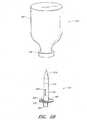
図3Aおよび図3Bには、医療用小型容器314からIVバッグ316へ正確な量の流体を供給するためのサブシステムまたは流体アセンブリ300を示す。図3Aはサブシステム300の斜視図であり、図3Bはサブシステム300の分解斜視図である。サブシステム300は、移行させられる流体を正確な量で測定するためのシリンジ318を含むことができる。いくつかの実施形態において、システムは、IVバッグアセンブリ330を含む。IVバッグアセンブリ330は、IVバッグ316、コネクタ332およびIVバッグ316とコネクタ332とを接続するチューブ部334を含むことができる。コネクタ332は、例えば雌型医療用コネクタであってもよい。図3A〜図3Bに示されるコネクタ332は、カリフォルニアのサンクレメンテのICU Medical, Incによって製造されるClave(登録商標)コネクタのバージョンのものであってもよい。このタイプのコネクタのさまざまな実施形態が特許文献1に開示されており、この参照によりその全体が本明細書に組み込まれる。このサブシステム300は、小型容器314、シリンジ318およびIVバッグアセンブリ330を相互連結するためのコネクタ320を含むことができる。 3A and 3B show a subsystem or
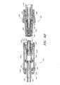
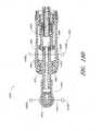
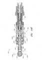
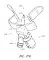
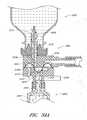
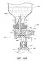
続いて図4Aおよび4Bに関して、図4Aにはコネクタの形態の流体移行モジュールの斜視図を示し、かつ図4Bにはコネクタ320の断面図を示す。コネクタ320は、コネクタ320と小型容器314との間に流体連通を提供するよう構成された第1のインターフェースまたは供給コネクタ部336と、コネクタ320とIVバッグアセンブリ330との間に流体連通を提供するよう構成された第2のインターフェースまたはターゲットコネクタ部と、コネクタ320とシリンジ318との間に流体連通を提供するよう構成された中間コネクタ部340とを含むことができる。コネクタは本体342を含むこともできる。図4Aおよび4Bに示される実施形態において、中間コネクタ部340は本体342の一部として一体的に形成されていてもよい。 Subsequently, with respect to FIGS. 4A and 4B, FIG. 4A shows a perspective view of the fluid transfer module in the form of a connector, and FIG. 4B shows a sectional view of the
いくつかの実施形態において、コネクタ320はT形状コネクタであってもよい。図示された実施形態においては、IVバッグアセンブリ330へ誘導する流動経路は小型容器314とシリンジ318との間の流動経路に対して実質的に直交している。さまざまな他の構造を使用することもできる。流動経路は、例えば傾斜した角度で交差するよう配置されてもよい。 In some embodiments, the
いくつかの実施形態において、供給コネクタ部336は、わずかにテーパー形状(先細形状)になされた内面を有する雌型コネクタ部344を含む。コネクタの本体342は対応する雄型コネクタ部346を有することができ、この雄型コネクタ部346は同様にテーパー形状になされた外面を有する。雌型コネクタ部344および雄型コネクタ部346は、雄型コネクタ部346が雌型コネクタ部344に完全に挿入された(つまりテーパー形状面同士がさらなる挿入を阻止する)場合に、雄型コネクタ部346の端部と雌型コネクタ部344の基部との間にチャンバ348に規定されるように、構成することができる。雄型コネクタ部346は、挿入前に雄型コネクタ部346の外面および/または雌型コネクタ部344の内面にプラスチック溶着接着(例えばジクロロメタン)を適用することによって、雌型コネクタ部344に固定できる。ジクロロメタンは、雄型コネクタ部346の外面を雌型コネクタ部344の内面に対して化学的に溶着させることができる。雄型コネクタ346を雌型コネクタ344に接続するために他の方法、例えば超音波溶着、ねじ切り、または接着剤などを使用することもできる。いくつかの実施形態において、本体342と供給コネクタ部336との間の接続部は気密密封されてもよく、ある実施形態においては気密密封を提供するためにO−リングなどのシーリング部材(図示せず)を含んでいる。 In some embodiments, the
いくつかの実施形態において、ターゲットコネクタ部338は、本体342に同様に取り付け可能である。本体342は雌型コネクタ部350を含むことができ、かつターゲットコネクタ部338はテーパー形状の外面を備えた雄型コネクタ部352を含むこともできる。雄型コネクタ部352が完全に雌型コネクタ部350に挿入された(つまりテーパー形状面同士がさらなる挿入を阻止する)場合に、雄型コネクタ部352の端部と雌型コネクタ部350の基部との間にチャンバ354が規定される。コネクタ部350,352は、上記のジクロロメタンまたは他の方法を使用して互いに固定可能である。いくつかの実施形態において、本体342とターゲットコネクタ部338との間の接続部は気密密封されており、ある実施形態においては密封部材を含むことができる。 In some embodiments, the
コネクタ320は、チャンバ348内に配置された供給チェックバルブ356を含むことができる。チェックバルブ356は、小型容器314からコネクタ320へ流体を流動可能にするがコネクタ320から小型容器314へ流体が流動することは防止するよう構成可能である。コネクタは、チャンバ354内に配置されたターゲットチェックバルブ358を含んでもよい。チェックバルブ358は、コネクタ320からIVバッグアセンブリへ流体を流動可能にするがIVバッグアセンブリからコネクタ320へ流体が流動することは防止するよう構成可能である。チェックバルブ356,358は以下に詳述される。
本体342はさまざまな材料から構成することができる。本体342は、ポリカーボネートまたは他のポリマー材料などの硬質な材料から構成できる。いくつかの実施形態において、本体342の少なくとも一部は以下に述べるように実質的に透明な材料から形成可能である。 The
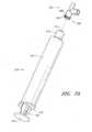
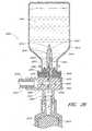
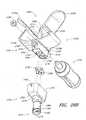
図5Aは、非係合構造体における供給コネクタ部336と小型容器314との斜視図である。図5Bは、同様に非係合構造体における供給コネクタ部336と小型容器314との他の斜視図である。図5Cは、係合構造体における供給コネクタ部336と小型容器314との断面図である。図5Dは、小型容器314から流体の一部が引き抜かれた後の、供給コネクタ部336と小型容器314との断面図である。図5Aから図5Dには簡単化のためにコネクタ320の残りの部分から分離されたコネクタ320の供給コネクタ部336が示されている。供給コネクタ部336は使用時にコネクタ320の残りの部分に連結可能であることを理解されたい。 FIG. 5A is a perspective view of the
ここで図5Aから図5Dを参照すると、小型容器314は、医療用流体を貯蔵するための適切な容器を備えることができ、かつ例えばイリノイのAbbott ParkのAbbott Laboratoriesによって製造されたような医療用小型容器とすることができる。いくつかの実施形態において小型容器314は本体357とキャップ359とを含む。いくつかの実施形態において、小型容器314は、気密密封されるよう構成され得る。本体357は、プラスチックまたはガラスなどの硬質な、実質的に不透過性の材料を備えることができる。ある実施形態においてキャップ359は、隔膜360およびケーシング362を含む。隔壁360は、ある部品によって穿孔される場合に隔膜がその部品の周囲に実質的に気密性の密封部を形成するような変形可能な弾性材料から形成できる。例えば、いくつかの例示においては、隔膜360は、シリコンラバーまたはブチルラバーを具備してなる。ケーシング362は、隔膜360を包囲でき、かつ小型容器314を密封するのに適切な材料から形成できる。いくつかの例においては、ケーシング362は、隔膜360と小型容器本体357との間に気密性の封止部を形成するために、隔膜360の周囲にかつ小型容器本体357の端部にクリンプされた金属を備える。いくつかの実施形態において、ケーシング362は、実質的に平坦な取り付け面364を含むことができる。小型容器314は、その内部の容積に医療用流体(例えば化学薬品)などの流体を含むことができる。小型容器314は、同時に内部容積内に収容される相対的に小さな量の滅菌空気も含むことができる。 Referring now to FIGS. 5A-5D, the
供給コネクタ部336は、外筒372と先細先端部374とを備えることができる穿孔部材370を含んでもよい。外筒372は、シリンダ形状のものであるが他の適切な形状のものとすることもできる。例えばいくつかの実施形態において、穿孔部材370は、隔膜360を通して挿入されるのに適した金属またはプラスチック(例えばポリカーボネートプラスチック)などの硬質材料を備えることができる。いくつかの例においては、先細先端部374は外筒372から分離可能である。他の実施形態において、先細先端部374および外筒372は、一体的に形成されるかまたは永続的に連結されていてもよい。先細先端部374は、隔膜360の穿孔を容易にするよう構成できる、供給コネクタ部336は、供給コネクタ部336を小型容器314に固定するために構成されたキャップコネクタ376を含むこともできる。いくつかの実施形態において、キャップコネクタ376はキャップコネクタ376の表面上に設けられた両面テープなどの接着剤378を含むこともできる。取り外し可能なカバー380(図5Bにおいては部分的に剥離された状態で示されている)は、すぐに接着剤を使用できるように接着剤378を覆うように配置可能である。小型容器314は、接着剤378から取り外し可能なカバー380によって、かつ穿孔部材370が隔膜360を穿孔しかつ取り付け面364が接着剤378と接触するように供給コネクタ部336に小型容器314を押し付けることによって、キャップコネクタ376に固定できる。コネクタ220の供給コネクタ部336に小型容器314を固定するために他のタイプのコネクタを使用することもできる。 The
いくつかの実施形態において、供給コネクタ部336は、流体366が引き出されたときに小型容器314内の自動的に圧力を均等にするよう構成できる。例えば、供給コネクタ部336は、カリフォルニアのクレメンテのICU Medical, Inc.によって製造されたGenie(登録商標)閉小型容器アクセスデバイスのバージョンであってもよい。このタイプの閉小型容器アクセスデバイスの特定の実施形態が特許文献2に開示されており、この参照によりその全体が本明細書に組み込まれる。例えば特許文献2には他の方法が開示されており、それにより小型容器314を供給コネクタ部336に接続することもできる。 In some embodiments, the
いくつかの実施形態において、供給コネクタ部336は、流体抽出チャネル382を含むことができる。この流体抽出チャネル382は、穿孔部材370の一部を介して穿孔部材370の側壁に形成された抽出開口383から延在する上部384を含むことができる。流体抽出チャネル382は、雌型コネクタ部344を介して延在する下部386を含むこともできる。特定の実施形態において、下部386は、下部386から上部384への変位部においてショルダ388を規定するよう上部384より幅広のものであってもよい。 In some embodiments, the
いくつかの実施形態において、外筒372は、小型容器324が供給コネクタ部336に固定された場合に環境空気にさらされたままとなる供給コネクタ部344の一部に形成される調整開口392まで外筒372を介してかつキャップコネクタ376を介して延在する調整チャネル390を規定する中空なものであってもよい。バッグは、調整チャネル390と流体連通状態にある内部容積395を規定できる。いくつかの実施形態において、バッグは、空気がバッグ394の内部容積395へ進入する場合を除いては空気が接続領域396を通過できないように、調整チャネル390の壁と気密性の封止部を形成する接続領域396を含むことができる。いくつかの実施形態において、バッグ394の接続領域396は、接着剤によってまたは他の適切な様式によって外筒372に固定できる。 In some embodiments, the
バッグ394は、折り畳まれない状態に比べてより小さな容積を占めるように、調整チャネル390内部で折り畳むことができる。バッグ394は、小型容器314の内部容積全体または内部容積の一部を満たすことが可能なように構成されている。いくつかの実施形態において、バッグ394は、Mylar(登録商標)、ポリエステル、ポリエチレン、ポリプロピレン、サラン、ラテックスラバー、ポリイソプレン、シリコンラバー、ポリウレタン、およびラテックス−フリー−シリコンなどの弾性材料を備えることができる。これはバッグ394の折り畳み、膨張および/または収縮を可能にする。いくつかの実施形態において、バッグ394は、液体および空気を不透過のものでありかつ流体366に対して抵抗性のない材料を具備してなる非膨張材料を備えることもできる。 The
図5Cには、流体366が抽出される前のステージにおける小型容器412に連結された供給コネクタ部336の一実施形態を示す。一方で図5Dには、流体がある程度抽出された後にバッグ394展開された状態のステージにおける、小型容器314に連結された供給コネクタ部336の一実施形態を示す。図5cおよび図5Cには示されないが、供給コネクタ部336の流体抽出チャネル382は、小型容器314から流体を抽出するために負圧を形成可能なシリンジ318あるいは他の医療器具と流体連通状態となることができる。ある状況においては、小型容器314内に圧力を降下させるシリンジによって所定の量の流体366を小型容器314から引き出し可能である。小型容器内の降下された圧力は、先端部374を外筒372から分離させることができる。それによりバッグ394は外筒372から抜け出て自由となる。流体366が小型容器314からシリンジ318へ向けて流出するにつれて、環境空気が調整チャネル390および調整開口392を介してバッグ394の内部容積395内に流入する。いくつかの状況においては、バッグ394の内部容積395は、小型容器314内部の低減された圧力に比例して(広がりかつ/または膨張することによって)膨張する。 FIG. 5C shows an embodiment of the
したがって、供給コネクタ部336は、小型容器314内の圧力を調整すると同時に、流体336が小型容器314から吸い出すことができるように構成できる。いくつかの実施形態において、供給コネクタ部336は、流体が小型容器314から引き出されても小型容器314内の圧力を実質的に一定に維持する。いくつかの実施形態において、小型容器314内の圧力は、流体336が引き出される間にわずか約1〜5psi(ポンド/平方インチ)しか変化しない。特許文献2には、供給コネクタ部336および小型容器314に適用可能な付加的な詳細およびさまざまな代替例が開示されている。 Therefore, the
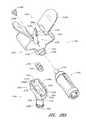
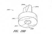
図6Aはターゲットコネクタ部338の斜視図である。図6Bはターゲットコネクタ部338の分解斜視図である。図6Cはターゲットコネクタ部338のハウジング部の平面図である。図6Dは非係合状態のターゲットコネクタ部338および雌型コネクタ332の断面図である。図6Eは非係合状態のターゲットコネクタ部338および雌型コネクタ332の断面図である。図6A〜図6Eにおいてはターゲットコネクタ部338はコネクタ320の残りの部分から切り離されて示されているが、ターゲットコネクタ部338が使用時にコネクタ320の残りの部分に接続可能であることを理解されたい。 FIG. 6A is a perspective view of the
図6A〜図6Eを参照すると、コネクタ320のターゲットコネクタ部338は閉鎖可能な雄型ルアーコネクタであってもよく、これは、対応する雌型コネクタとの分離時には流体がコネクタから浸出したりコネクタ内に進入したりすることを防止するが、対応する雌型コネクタ332との係合時には流体の流通を可能にするよう構成されている。図示された実施形態において、ターゲットコネクタ部338は、カリフォルニアのサンクレメンテのICU Medical, Inc.によって製造されているSpiros(登録商標)閉鎖可能な雄型コネクタのバージョンのものであってもよい。このタイプのコネクタのさまざまな実施形態が特許文献3に開示されており、この参照によりその全体が本明細書に組み込まれる。図6A〜図6Eに示された実施形態においてはコネクタ332は雌型コネクタとしてかつターゲットコネクタ部338は雄型コネクタとして示されているが、他の構成を採用することも可能であることに留意されたい。例えばコネクタ332は雄型コネクタとし、その一方でターゲットコネクタ部338を雌型コネクタとすることもできる。いくつかの実施形態において、流体移行システム100内において、対応して自動的に閉鎖可能な雄型および雌型コネクタを提供することによって、少なくとも一部分において、異なる(またはすべての)接続ポイントにおいて実質的に全体的にまたは全体的に閉じられたシステムを得ることができる。それにより、静止流体が、コネクタ分離時に実質的に全体的に流体供給源、流体モジュールおよび流体ターゲット部のそれぞれに留まるようにさせられ、そしてほとんどの場合システムの外部への漏出または気化がなくなる。例えばいくつかの実施形態において、対応する一対の自動閉鎖コネクタ(例えば雄型および雌型コネクタ)が、流体供給源と流体モジュールとの間、流体モジュールと中間容器との間、および/または流体モジュールと目的地つまりターゲット容器との間のインターフェースに提供されてもよい。 With reference to FIGS. 6A-6E, the
ターゲットコネクタ部338は、ハウジング398、バルブ部材400、弾性部材402、封止リング404、端部キャップ406、およびO−リング407を含むことができる。ハウジング398は、略円筒状の形状のものであってもよく、かつハウジングを通って軸線方向に延在する通路408を含むことができる。図示されるように、通路408は、コネクタの各側部における開口を有する。ハウジング398は、基部412においてハウジング398の架台に接続される雄型ルアー先端部410を含んでもよい。ルアー先端部410は、通路408の一部がその中で規定されるように略円筒状の形状を有することができ、かつルアー先端部410は、その端部において通路408への入口を提供する孔414を含むことができる。いくつかの実施形態において、ルアー先端部410は、通路408の軸線方向に向かって半径内側方向に延在するシェルフ416を含む。シェルフ416は、通路408がルアー先端部410の端部において幅狭となるように、孔414に近接して配置されることができる。いくつかの実施形態において、シェルフ416のうち、半径方向内側に面する表面は、通路408が孔414に直に近接するところで最も幅狭となるように、先細りしている。いくつかの状況において、シェルフ416は、バルブ部材400の一部がシェルフ416に当接した際に通路を封止するよう構成できる。図示されるように、いくつかの実施形態において、コネクタは、コネクタが閉鎖された際に流路内の流体がコネクタから漏出したり、気化したり、あるいは他の方法で開口を介して浸出することを実質的に全体に防止するように使用可能である。 The
ルアー先端部410は、遮壁418によって取り囲まれていてもよい。いくつかの実施形態において、ルアー先端部410は、遮壁の縁部420を越えてある程度の距離にわたって延在している。遮壁418は、その内面に内部ねじ切り部422を含むことができる。内部ねじ切り部422は、雌型コネクタ322を固定するために使用できる。ねじ切り部は、ハウジングの他の部分の直径よりも小さな外径を有する凹部424を含むことができる。凹部424は、弾性部材402の一部と係合するよう構成可能である。 The
ハウジング398は、2つのギャップ428a,428bによって離間された2つの壁部426a,426bを含むことができる。ギャップ428a,428bは、弾性部材402の一部を収容するよう構成できる。壁部426a,426bは、端部キャップ406と係合するよう構成できる。 The
いくつかの実施形態において、ハウジング398は中間部430を含み、中間部430は、実質的に壁部426a,426bの間に配置され、かつギャップ428a,428bの付近で壁部426a,426bに連結される。いくつかの実施形態において、孔432a,432bが中間部430と壁部426a,426bとの間に規定される(図6C参照)。いくつかの実施形態において、ルアー先端部410は、その基部412における中間部430に連結される。いくつかの実施形態において、中間部は、その通路408の一部を規定する。いくつかの実施形態において、中間部430の外面の一部434がギャップ428a,428bによって露出されている。この部分434は、ノッチ436a,436bおよび貫通孔438a,438bを含むことができる。ノッチ436a,436bは、略矩形状の形状を有し、かつノッチ436a,436bがそれらの表面付近ではなくそれらの基部の付近では幅狭となるようにテーパー形状を有することもできる。貫通孔438a,438bは略矩形状の形状を有することもできる。 In some embodiments, the
ハウジング398はさまざまな材料から構成することができる。ハウジング398は、ポリカーボネートまたは他のポリマー材料などの硬質材料から構成することができる。いくつかの実施形態において、ハウジング398は、Bayer Makrolonなどの疎水性材料または他の適切な材料から構成することができる。いくつかの実施形態において、ハウジング398は、実質的に透明な材料から形成できる。 The
バルブ部材400は、基部444に形成された開口からチューブ446へ軸線方向に延在する流体通路440を含むことができる。いくつかの実施形態において、通路440はチューブ446よりも基部444において、より幅広なものとすることができる。いくつかの実施形態において、チューブ446は幅狭先端部448を含む。ある実施形態において、先端部448は先細形状の外面を有することができる。先端部448は、シェルフ416のうち半径方向内側に面する面と同じ角度で実質的に先細りしており、かつ先端部448がシェルフ416と当接した際にシェルフ416との流体密封部を形成できるサイズのものであってもよい。いくつかの実施形態において、先端部448は、先端部448とシェルフ416との間の流体封止部の形成を容易にするために例えばシリコンラバーなどのフレキシブルなまたは圧縮可能な材料から形成することができる。いくつかの実施形態において、チューブは、流体通路440への流入部を提供するために1つ以上の孔450を含むことができる。孔450は例えばチューブ446の先端部448に形成することもできる。 The
いくつかの実施形態において、バルブ部材400は、2つの支柱452a,452bを含むことができる。この支柱452a,452bは、基部444から延在しかつチューブ446の各側方に配置されており、それによりチューブの各側方に解放された空間が規定される。いくつかの実施形態においてチューブ446は支柱452a,452bの端部を越えて軸線方向に延在することができる。 In some embodiments, the
バルブ部材400の基部444は、その外面から半径方向外側へ延在する複数の突出部454を含むことができる。いくつかの実施形態においてこれら突出部454は、それらの間に2つのチャネル456a,456bを規定するよう配置できる。いくつかの実施形態において、突出部454は、基部444の長さ全体にわたってではなく、実質的に滑らかな外面を有する基部444の下部458を残した状態で延在している。 The
バルブ部材400は、ポリカーボネートまたは他のポリマー材料などのさまざまな材料から構成することができる。いくつかの実施形態において、バルブ部材400はハウジング398と同じ材料から構成することができる。いくつかの実施形態において、バルブ部材400およびハウジング398は異なる材料から形成されてもよい。いくつかの実施形態において、バルブ部材400は、複数の材料または複数の部品から構成することもできる。例えば、先端部448は、バルブ部材400の他の部分よりさらにフレキシブルな材料から構成できる。いくつかの実施形態においてバルブ部材400は実質的に不透明な材料から形成することもできる。 The
弾性部材402は、弾性部材464a,464bによって互いに連結された第1のリング460と第2のリング462とを含むことができる。弾性部材464a,464bは、シリコンラバーなどの伸長時に復元力を発揮する弾性材料から形成できる。したがって、リング460,462が離間されるよう引っ張られると、弾性部材464a,464bは、リング460,462をその弛緩された構造まで元に戻すよう作用する。いくつかの実施形態において、リング460,462は、弾性部材464a,464bを形成するのに使用される材料と同じ材料などの弾性材料から構成することもできる。いくつかの実施形態において、第2のリング462は、第1のリング460よりも大きな直径を有することができる。いくつかの実施形態において、第2のリング462は、第1のリング460に近接する第2のリング462の端部が第1のリング460から離れた側に位置する第2のリング462の端部よりも幅広となるよう先細の外表面を有することができる。 The
封止リング404は、略円筒の形状を有することができ、かつそれを通って軸線方向に延在する孔466を有することができる。封止リング404は、円筒形本体部468と、本体部468の一端に配置されるO−リング470を有することができる。いくつかの実施形態において、O−リング470の最薄手部分は、最薄手部分が本体部468の内面から距離をおいて孔466の軸線方向へ向けて半径方向内側に延在するように、本体部468よりも薄手のものとすることができる。したがって、孔466は、本体部468おけるよりもO−リング470の最薄手部分において幅狭となっていてもよい。いくつかの実施形態において、O−リング470の最薄手部分はまた、本体部468の外面から距離をおいて半径方向外側へ延在している。封止リング404は、本体部468から半径方向外側に延在する2つの突出部472a,472bを含むことができる。いくつかの実施形態において、突出部472a,472bは略矩形状のものとすることができる。 The sealing
封止リング404はさまざまな材料から構成することができる。いくつかの実施形態において、封止リング404は、シリコンラバーなどの変形可能なまたは弾性材料から構成することができる。いくつかの実施形態において、封止リング404は、弾性部材402を形成するために使用される材料と同じ材料から構成することもできる。いくつかの実施形態において、封止リング404は、硬質プラスチックまたは他の硬質ポリマー材料に対する流体封止部を形成する能力のある材料から構成することができる。 The sealing
端部キャップ406は、第1の端部キャップ部材405と第2の端部キャップ部材409とを含むことができる。第2の端部キャップ部材409は、雄型コネクタ352と、プランジャ474と、雄型コネクタ352とプランジャ474との間に配置されたディスク部476とを含むことができる。第2の端部キャップ部材409は、その中において軸線方向に設けられた流体通路478を有することができる。いくつかの実施形態においてプランジャ474は略管状の形状のものとすることができる。いくつかの実施形態において、プランジャ474の外面は、O−リング407を収容するよう構成可能な凹部領域480を含む。O−リング407は、O−リング407がプランジャ474の縁部482にわたって伸長させられかつ凹部領域480内に設置可能なように、シリコンラバーなどの弾性材料から構成することができる。いくつかの実施形態において、O−リング407は、弾性材料402および/または封止リング404と同じ材料から構成することができる。いくつかの実施形態において、O−リング407は、凹部領域480内に配置されたときにO−リング407の最薄手部分がプランジャ474の外面から距離をおいて半径方向外側に延在するようなサイズすることができる。 The
いくつかの実施形態において、通路478は、第2の端部キャップ部材409にわたって実質的に一定の幅を有することができる。いくつかの実施形態において、通路478は、プランジャ474におけるよりも雄型コネクタ352においてより幅広なものとなるようなテーパー形状にすることができる。いくつかの実施形態において、通路478は、例えば凹部領域480と適合するよう、プランジャ474の端部の付近で幅狭となっていてもよい。 In some embodiments, the
第1の端部キャップ部材405は、略錐台形のものとすることができ、かつその中に中央開口471を有することができる。組み立て時に、プランジャ474は、中央開口471を通って延在する。蓋473が、中央開口471の内部に向けて延在することができる。蓋473は、第1の端部キャップ部材405を第2の端部キャップ部材409に固定するために、プランジャ474の基部と第2の端部キャップ部材409におけるディスク部476との間に形成されたチャネル475へと収容することができる。蓋473および対応するチャネル475は、第1の端部キャップ部材405を第2の端部キャップ部材409に対して長手軸線方向の周囲で回転可能にすることができる。したがって、第1の端部キャップ部材405および第2の端部キャップ部材409は、端部キャップ406を形成するよう連結可能である。 The first
バルブ端部キャップ406はポリカーボネートまたは他の硬質なポリマー材料などのさまざまな材料から構成することができる。いくつかの実施形態において、端部キャップ406は、ハウジング398および/またはバルブ部材400と同じ材料から構成することもできる。 The
いくつかの実施形態において、端部キャップ406は、バルブ部材400および/またはハウジング398とは異なる材料から構成することができる。第1の端部キャップ部材405は、第2の端部キャップ部材409と同じ材料から構成することができるが、異なる材料を使用することもできる。いくつかの実施形態において、第1の端部キャップ部材405または第2の端部キャップ部材409あるいはその両方を実質的に透明なものとすることができる。 In some embodiments, the
ターゲットコネクタ部338のさまざまな部分同士の間の特定の相互連結について以下に詳細に説明する。封止リング404は、ハウジング398の中間部分430の内側に配置できる。突出部472a,472bは、突出部472a,472bが貫通孔438a,438bと係合するようなサイズおよび配置とすることができる。したがって封止リング404は、封止リング404がチューブ446に対して軸線方向に回転または動作しないように、ハウジング398に固定可能である。 Specific interconnects between the various parts of the
バルブ部材400は、チューブ446が通路408に入るように、ハウジング398内にスライド可能に挿入され得る。チューブ446の幅狭先端部448は、シェルフ416に当接するまで雄型ルアー先端部410内へ封止リング404の孔446を通過可能である。チューブ446は、孔446を実質的に満たす幅を有し、かつそれらの間に流体封止部を形成するよう封止リング404のO−リング470部分を押圧することができる。支柱452a,452bは、支柱452a,452bが雄型ルアー先端部410および遮壁418との間に配置されるように、ハウジング398内の孔432a,432bをそれぞれ通過できる。 The
弾性部材402は、ハウジング398に対してバルブ部材400を付勢するよう機能する。第1のリング460は、リング460の表面が突出部454に当接するように、バルブ部材400の基部444の下部458に嵌合可能である。第2のリング462は、ハウジングの凹部424内に嵌合可能である。弾性部材464a,464bは、チャネル456a,456b内にそれぞれ配置可能であり、かつハウジング398の壁部426a,426bの間のギャップ428a,428bを通過可能である。 The
O−リング407は、上述したように端部キャップ406の凹部領域480上に配置でき、かつプランジャ474は、バルブ部材の通路内に少なくとも部分的にスライド可能に挿入できる。いくつかの実施形態において、O−リング407の最薄手部分は、O−リング407が通路440の内面に対する流体封止状態を形成するように、バルブ部材400の基部に形成された通路440の部分よりも幅広のものとすることができる。プランジャ474は、端部キャップ406のディスク部476がハウジング398の壁部426a,426bの端部と接触するまで、バルブ部材400内に挿入可能である。 The O-ring 407 can be placed on the recessed
いくつかの実施形態において、壁部426a,426bは、超音波溶着、スナップ嵌合構造(図示せず)、圧力または摩擦嵌め、または他の適切な連結タイプのものによって、第1の端部キャップ部材405の上面477に固定できる。上述したように、第1の端部キャップ部材405は、第1の端部キャップ部材405を第2の端部キャップ部材409に対して回転可能にする様式で、第2の端部キャップ部材409に固定可能である。したがって、一度ターゲットコネクタ部338が組み立てられると、ハウジング398、封止リング404、弾性部材402、バルブ部材400、および第1の端部キャップ部材405は、長手方向軸線の周囲で第2の端部キャップ部材409に対して回転可能となる。 In some embodiments, the
図6D〜図6Eを参照すると、ターゲットコネクタ部338は、雌型コネクタ332に係合するよう構成できる。さまざまなタイプの雌型コネクタ332を使用することができる。図示された雌型コネクタ332は、ハウジング490と、スパイク(spike)492と、基部494と、弾性封止要素496とを含む閉鎖可能な雌型ルアーコネクタである。流体通路498が基部およびスパイク492を通過可能である。スパイク492は、通路498とスパイク492の外側との間の流体連通をもたらす1つ以上の孔500を含むことができる。封止要素496は、スパイク492の実質的に取り囲むような形状および配置にすることができる。封止要素496は、閉鎖可能な開口502、あるいは封止要素496が(図6Eに示されるように)圧縮された場合にスパイク492の先端部が封止要素496の端部を通過できるように解放可能なスリットを含むことができる。ハウジングは、ターゲットコネクタ部338のハウジング398における内部ねじ切り部422と係合するよう構成された外部ねじ切り部504を含むことができる。チューブ334の端部は、接着剤、クランプ、摩擦または圧力嵌め、あるいは液密連結部を形成する他の適切な様式で、雌型コネクタ332の端部に連結可能である。 With reference to FIGS. 6D-6E, the
上述したように、いくつかの実施形態において、ハウジング398、封止リング404、弾性部材402、バルブ部材400および第1の端部キャップ部材405は、長手方向軸線の周囲で第2の端部キャップ部材409に対して回転可能である。したがってIVバッグアセンブリの雌型コネクタ322は、ターゲットコネクタ部338に取り付けられ、雌型コネクタ332は、ターゲットコネクタ部338のハウジング398がねじ切り部504,422の係合をもたらすよう回転可能な間にわたって保持可能となる。雌型コネクタ322は、ターゲットコネクタ部338と着脱される間に回転させられる必要はないため、チューブ334がねじれたり、もつれたりすることが防止でき、かつ使用者は、雌型コネクタ322の回転に適応させるためにIVバッグをねじる必要がなくなる。こうした回転能力を備えるコネクタの実施形態が、参照によりその全体が本明細書に組み込まれた特許文献3により詳細に記載されている。 As mentioned above, in some embodiments, the
(図6Dに示されるように)雌型コネクタ322が係合しない場合には、ターゲットコネクタ部338は封止可能である。いくつかの実施形態において、流体は、雄型コネクタ352においてターゲットコネクタ部338に流入し、かつ端部キャップ406の通路478を通り、バルブ部材400の通路440を通り、孔450を通り、かつ雌型ルアー先端部410によって規定された通路408の一部へと流動する。しかしながら、雌型ルアー先端部410のシェルフ416を押圧するバルブ部材400の先端部448によって形成される流体封止部は、ターゲットコネクタ部338から流体が流出することを防止する。いくつかの実施形態において、付加的な流体がターゲットコネクタ部338に入る場合などにおける圧力の増大は、先端部448をよりしっかりとシェルフ416に押圧させるようにし、それにより、流体封止性が向上される。 If the
ターゲットコネクタ部338が(図6Eに示されるように)雌型コネクタ332と係合する場合、雌型ルアーコネクタ322の外部ねじ切り部504は、雌型コネクタ322をターゲットコネクタ部338に固定するよう隔壁418における内部ねじ切り部422と係合可能である。雌型ルアー先端部410の縁部は、孔500が露出されるまでスパイク492が開口502を通過するように、弾性封止要素496を押圧しかつ圧縮することができる。雌型ルアーコネクタ332のハウジング490の端部は、それが支柱452a,452bと接触するまで、雌型ルアー先端部410および隔壁418との間の空間に侵入することができる。雌型ルアーコネクタ322がターゲットコネクタ部338とさらに係合すると、それは、支柱452a,452bを押圧してバルブ部材400全体を後退させることができる。バルブ部材400が後退すると、弾性部材402の弾性部材464a,464bが伸長する。バルブ部材400が後退した場合には、先端部448はシェルフ416から離れ、流体封止部を分断させ、かつ孔500を介してターゲットコネクタ部338のハウジング398における通路408から雌型コネクタ322における通路498まで流体を流通可能にする。係合時には、弾性封止要素496は、雄型ルアー先端部410の端部に封止要素496をそれらの間に流体封止部を形成するように押し付けるターゲットコネクタ部338へ向けて復元力を作用させる。したがって、流体がターゲットコネクタ部338から雌型コネクタ322へ移行させられる一方で、流体は外部環境から遮断された状態で維持可能となる。 When the
雌型コネクタ322は、ターゲットコネクタ部338から分離することができる。雌型コネクタ332の弾性封止要素496によって作用する復元力は、その通路498を封止するように、その閉鎖ポジションに雌型コネクタ332を復元させる。弾性部材402の弾性部材464a,464bは、バルブ部材400に復元力を及ぼし、バルブ部材は、雌型コネクタ332が分離されるとシェルフ416に当接されていたその先端部448とともにその閉鎖ポジションへ戻るようになされる。 The
特許文献3には、コネクタ320のターゲットコネクタ部338に適用可能な付加的な詳細およびさまざまな代替例が開示されている。 Patent Document 3 discloses additional details and various alternatives applicable to the
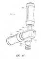
図7Aは、非係合構造におけるシリンジ318およびコネクタ320の中間コネクタ部340の斜視図である。図7Bは、係合構造におけるシリンジ318および中間コネクタ部の平面図である。図7cは、係合構造におけるシリンジ318および中間コネクタ部340の断面図である。図7A〜図7cには簡単化のためにコネクタ320の残りの部分から分離されたコネクタ320の本体342を示すが、本体342は、使用時にコネクタ320に連結可能であることを理解されたい。 FIG. 7A is a perspective view of the
図示された実施形態において、中間コネクタ部340は、コネクタ320の本体342の一部と一体化されている。他の構成を採用することも可能である。例えばいくつかの実施形態において、中間コネクタ部340は、本体342に連結された別体の部品であることもできる。中間コネクタ部340は、雌型コネクタ506を含むこともできる。いくつかの実施形態において、雌型コネクタ506は先細形状の内面を有することができる。雌型コネクタ506の外面は外部ねじ切り部508を含むことができる。 In the illustrated embodiment, the
シリンジ318は、内部容積511を規定する中空シリンジ本体510を有することができる。シリンジは、一端において雄型ルアー雄型ルアー先端部512と、雄型ルアー先端部512を包囲する遮壁514とを含むことができる。隔壁514は内部ねじ切り部516を含むことができる。雄型ルアー先端部512およびねじ切りされた隔壁514は、コネクタ320の中間コネクタ部340における雌型コネクタ506と、それらの間に液密連結を形成するように、固定状態で係合するよう構成することができる。シリンジ本体510は、雄型ルアー先端部512に対向する本体の端部に配置された本体フランジ518を含むことができる。シリンジは、シリンジ本体510の内部容積内にスライド可能に収容されるプランジャ520含むこともできる。プランジャ522は、ストッパー522または本体510の内面に対する液密封止部を形成するよう構成された他の封止部材を含むことができる。プランジャ520には、ストッパー522の対向する端部において、プランジャフランジ524を配置することができる。 The
いくつかの実施形態において、雌型コネクタ506および雄型ルアー先端部512は、分離時に大気中に解放することができる。他の構成を使用することもできる。例えばいくつかの実施形態において、雌型コネクタ506は、上記雌型コネクタ332と同様の封止雌型コネクタとすることができ、かつ例えばClave(登録商標)コネクタのバージョンのものとすることができる。同様にシリンジ318は封止雄型コネクタを含むことができ、あるいは封止雄型コネクタはシリンジ318と雌型コネクタ506との間に連結可能である。いくつかの実施形態において、封止雄型コネクタは、Spiros(商標)コネクタのバージョンのものとすることができる。したがっていくつかの実施形態において、シリンジ318内の流体およびコネクタ320内の流体は、シリンジ318とコネクタ320とが互いに分離された場合であっても周囲環境から遮断可能となっている。 In some embodiments, the
いくつかの実施形態において、シリンジ318が(図7Bに示されるように)コネクタ320と係合する際には、シリンジ318の内部容積511は双方向においてコネクタ320と流体連通することができる。したがってプランジャ520が後退すると、流体は、コネクタ320からシリンジ318の内部容積511内へ吸引可能となる。続いてプランジャ520が前進させられると、流体は、内部容積511からコネクタ320へ方向付け可能となる。 In some embodiments, when the
簡単に上述したように、コネクタ320は、供給チェックバルブ356およびターゲットチェックバルブ358を含むことができる。チェックバルブ356,358は、流体がコネクタ320を介して小型容器314からシリンジ318へ流動可能となるように、プランジャ520が後退した際に供給チェックバルブ356が解放されかつターゲットチェックバルブ358が閉じされるように、機能することができる。続いて、プランジャ520が前進させられた際には、流体がシリンジ318からコネクタ320を経てIVバッグ316へ流動可能となるように、供給チェックバルブ356が閉鎖されかつターゲットチェックバルブ358が解放可能となる。 Briefly as described above, the
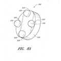
図8Aは、供給チェックバルブ356を示す斜視図である。図8Bは、異なる角度から見た供給チェックバルブ356を示す他の斜視図である。供給チェックバルブ356は、ディスク形状基部526を含むことができる。複数の脚部528が基部526の片側から軸線方向に延在可能である。図示された実施形態において、供給チェックバルブ356は、4つの脚部528を含むが、他の数の脚部528、例えば3つの脚部または5つの脚部あるいは他の適切な数の脚部528を使用することもできる。いくつかの実施形態において、脚部528は、それぞれが略円筒形状を有することができ、かつそれぞれが丸みのある先端部530を含むこともできる。他の形状および構成を採用することもできる。供給チェックバルブ356は脚部528に対向する側部に配置された封止面531を有することができる。 FIG. 8A is a perspective view showing the
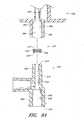
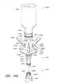
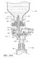
図9Aは、供給コネクタ部336、供給チェックバルブ356、および本体342の分解断面図である。図9Bは、チェックバルブ356が解放状態にある組み立て構造体における、供給コネクタ部336、供給チェックバルブ356、および本体342の断面図である。上述したように、供給コネクタ部336は、上部幅狭部384と下部幅広部386とを有する流体抽出チャネル382を含むことができる。ショルダ388を、流体抽出チャネル382の上部384から下部386への移行部に規定することができる。いくつかの実施形態において、抽出チャネル382の下部386は、下部386がショルダ388の付近で幅狭なものとなるように、先細形状の内面を有することができる。上部384もまた、上部384がショルダ388の付近で幅広なものとなるように、先細形状の内面を有することができる。いくつかの実施形態において、上部384および/または下部386は、実質的に円筒形のものとすることができるか、もしくは、実質的に一定の断面積を有する他の異なる形状を呈することができる。 FIG. 9A is an exploded cross-sectional view of the
本体342は、雄型コネクタ346の端部534から中間コネクタ部340の端部534まで延在する第1の流体通路532を含むことができる。第1の流体通路532は、上部536と下部538とを含むことができる。下部538は、ショルダ540を規定する上部536よりも幅広なものであることができる。上部536および下部538は、先細形状の内面または先細形状ではない内面を有することができる。組み立て時に、供給チェックバルブ336は、雄型コネクタ346の端部534と流体抽出チャネル382のショルダ388との間に配置されたチャンバ348内に配置可能である。供給チェックバルブ356は、封止面531がショルダ388へ向かって面することができると同時に、脚部528が雄型コネクタ346の端部534に向かって面するように配置可能である。いくつかの実施形態において、流体通路332内の圧力が抽出チャネル382内の圧力より十分に高くなった場合、例えばシリンジ318のプランジャ520が流体を流体通路332内へ押し出すよう前進させられる場合、供給チェックバルブ356は本体342から離れるよう押圧され、かつ封止面531は、第1の流体通路532から抽出チャネル382の上部へ流体が流入することを防止する液密封止部を形成するショルダ388と係合する。いくつかの構造において、流体通路332内の圧力が抽出チャネル382内の圧力よりも十分に低くなった場合、例えばシリンジ318のプランジャ520が流体通路332から流体を引き出すように後退する場合、供給チェックバルブ356はショルダ388から離れるよう引っ張られ、かつ脚部528は開放ポジションにおいて雄型コネクタ346の端部534に支えられるようになる。 The
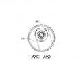
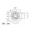
図10Aは、コネクタ320の供給コネクタ部336に連結された本体342の側面図である。図10Bは、コネクタ320の供給コネクタ部336およびその中に配置された供給チェックバルブ356の断面図である。図10Cは、雌型コネクタ344の壁によって半径方向に規定されたチャンバ348内に配置された供給チェックバルブ356を示す部分断面図である。図10Dは、チャンバ328内に配置された供給チェックバルブ356を示す他の断面図である。 FIG. 10A is a side view of the
図10A〜図10Dを参照すると、供給チェックバルブ356の基部526は、ディスク形状のものとすることができ、かつチャンバ438の直径d2未満の直径d1を有することができ、供給チェックバルブ356の側縁部と流体が流通可能なチャンバ348の内壁との間の空間542が規定される。またこれら脚部528は、隣接する脚部528同士の間に開口領域544が規定されるように離間できる。 With reference to FIGS. 10A-10D, the
したがって、供給チェックバルブ356が開放ポジションにあるときに、流体は、抽出チャネル382の上部384から、チャンバ384へ、そして供給チェックバルブ356の側縁部とチャンバ348の内壁との間の空間542を通って、脚部528同士の間の開口領域544を通って、第1の流体通路532の上部536へと流動可能となる。 Thus, when the
いくつかの実施形態において、供給チェックバルブ356は、際立ったボトルネック部を有することなく、チェックバルブ356の周囲の実質的に解放された流動を可能にするよう構成できる。例えば、供給チェックバルブ356の側縁部とチャンバ348の内壁との間の空間542は、チャンバ348の付近に設けられた抽出チャネル382の上部483の断面積A2に比べて少なくとも大きい断面積A1を有することができる。この関係は、以下の式(1)で表すことができる。 In some embodiments, the

いくつかの実施形態において、チャンバ348および供給チェックバルブ356は、いずれも(図10Cおよび図10Dに示されるように)それぞれ直径d2およびd1を有する実質的に円筒形のものとすることができる。供給チェックバルブ356の側縁部とチャンバ348の内壁との間の空間542の断面積A1は、以下の式(2)によって規定できる。 In some embodiments, the
いくつかの実施形態において、チャンバ348の付近に設けられた抽出チャネル382の上部483は、実質的に円筒形のものとすることができ、かつ(図10Dに示されるように)直径d3を有することができる。面積A2は以下の式(3)によって規定できる。 In some embodiments, the upper 483 of the
式(2)および式(3)を代入することによって、式(1)は以下の式(4)のように書き換えることができる。 By substituting the equations (2) and (3), the equation (1) can be rewritten as the following equation (4).
d1に関して式(4)を解くと、式(4)は以下の式(5)のように書き換えることができる。 When the equation (4) is solved for d1, the equation (4) can be rewritten as the following equation (5).
したがって、チャンバ348の直径d2と抽出チャネル382の上部483の直径d3とが判明し、供給チェックバルブ356は、流体が空間542を通過した際に流体の流通の妨害を防止するよう式(5)を満たす直径を有することができるようになる。 Therefore, the diameter d2 of the
図10Dに示されるように、いくつかの実施形態において、供給チェックバルブ356が開放ポジションにあるときに、高さh1を有する空間546が封止面531とショルダ388との間に規定される。この空間546は流体が流通可能なものとすることができる。いくつかの実施形態において、供給チェックバルブ356およびチャンバ348は、流体が空間546を通過する際の流通のボトルネックとなることを防止するよう構成することができる。例えば図示された実施形態において、空間546のうちの流体が流通可能な最小面積は、h1の高さとd3の直径とA3の表面積とを有する想像上の解放円筒体として示される。想像上の円筒体の表面積A3がチャンバ348の付近に設けられた抽出チャネル382の上部483の断面積A2と少なくとも同じ程度である場合、ボトルネックは低減できる。この関係は以下の式(6)のように表すことができる。 As shown in FIG. 10D, in some embodiments, a
上記想像上の解放円筒体の表面積A3は、以下の式(7)で表すことができる。 The surface area A3 of the imaginary open cylinder can be expressed by the following equation (7).
式(3)および式(7)を代入することによって、式(6)は以下の式(8)のように書き換えることができる。 By substituting the equations (3) and (7), the equation (6) can be rewritten as the following equation (8).
h1に関して解くと、式(8)は以下の式(9)のように書き換えることができる。 Solving for h1, Eq. (8) can be rewritten as Eq. (9) below.
したがって、抽出チャネル382の上部483の直径d3が判明すれば、供給チェックバルブ356は、抽出チャネル382の上部483から供給チェックバルブ356とショルダ388との間の空間546内へ流体が流動する際のボトルネックを低減させるために、少なくともd3/4によってチャンバ348の高さより小さな全高を有するよう形成され得る。 Therefore, if the diameter d3 of the upper 483 of the
供給チェックバルブ356は、脚部528同士の間の(図10Cに示される)開口領域544を介して流体が流動する際に流体のボトルネックとなる部分を低減させるよう構成できる。例えば、脚部528同士の間の開口領域544の全面積A4がチャンバ348の付近に設けられた抽出チャネル382の上部483の断面積A2と少なくとも同じ程度である場合に、抽出チャネル382からかつチェックバルブ356の周囲で流体が流動する際に、ボトルネックを低減させることができる。この関係は以下の式(10)で表すことができる。 The
図示された実施形態において、脚部528は、その縁部が脚部528のそれぞれと交差部するよう(図10Cに点線で示される)上記想像上の解放円筒体が配置可能なように構成されている。脚部528は、想像上の円筒体が直径d4を有するように配置されてもよい。いくつかの実施形態において、供給チェックバルブ356は、それぞれが実質的に等しい直径d5および実質的に等しい高さh2を有する数nの脚部を含む。開口領域544の領域全体の面積A4は、以下の式(11)によって規定することができる。なお、脚部528が丸みのある先端部530を有するため、この面積A4が式(11)によって示されるものよりわずかに大きくなり得ることに留意されたい。いくつかの実施形態において脚部528は、丸みのある先端部を有しておらずかつ実質的に円筒形状のものとすることができる。 In the illustrated embodiment, the
式(3)および式(11)を代入することによって、式(10)は以下の式(12)のように書き換えることができる。 By substituting the equations (3) and (11), the equation (10) can be rewritten as the following equation (12).
式(12)を満たす脚部528を使用することによってボトルネック部を低減することができる。例えば、脚部の数nまたは直径d5が増大される場合、補償のために、脚部の高さh2は増大可能であり、あるいは、脚部は周縁部に対してより近接するよう移動させる(d4の増大)ことができる。 The bottleneck portion can be reduced by using the
いくつかの実施形態において、供給チェックバルブ356は、流体の実質的に均一な流動を提供するよう構成できる。例えば供給チェックバルブ356の側縁部とチャンバ348の内壁との間の空間542は、チャンバ348の付近に設けられた抽出チャネル382の上部483の断面積A2と実質的に等しい断面積A1を有することができる。同様に、想像上の円筒体の断面積A3は、チャンバ348の付近に設けられた抽出チャネル382の上部483の断面積A2と実質的に等しいものとすることができる。また、脚部528同士の間の開口領域544の全面積A4は、チャンバ348の付近に設けられた抽出チャネル382の上部483の断面積A2と実質的に等しいものとすることができる。供給チェックバルブ356およびチャンバ348は、流路の他の領域が、チャンバ348の付近に設けられた抽出チャネル382の上部483の断面積A2と実質的に等しい面積を有するように構成することができる。例えばいくつかの実施形態において、ショルダ388またはチェックバルブ356の封止面531は、抽出チャネル382の上部483の付近におけるよりも空間546の高さが側方空間542の付近においてより小さなものとなるよう、テーパー形状を有していてもよい。いくつかの実施形態において、本明細書に記載された面積が、その面積が許容可能な公差T未満の量まで変化させられた場合に、実質的に等しくなるよう考慮されている。いくつかの実施形態において公差Tは、約1mm、0.5mm、0.1mm、0.05mmあるいは0.01mm未満とすることができる。いくつかの実施形態において、チェックバルブ356の周囲の流動面積は、(例えばA1、A3およびA4)は、公差T未満の量までA2よりも小さいものとすることができる。したがっていくつかの実施形態において、小さいが許容可能なボトルネック部の量は、流体が供給チェックバルブ356の周囲で流動する際に発生し得る。In some embodiments, the
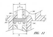
いくつかの実施形態において、チャンバ348の直径d2は、供給チェックバルブ356の直径d1よりも大きく、供給チェックバルブ356は、チャンバ内で軸線方向だけでなく、チャンバ内で半径方向にも動作可能である。例えば図11には、閉鎖ポジションにあるときのチャンバ348の片側に対して配置された供給チェックバルブ356の断面図が示される。供給チェックバルブ356の直径d1は、チャンバ348の片側に対して配置された場合に、供給チェックバルブ356がチャンバ388を適切に封止することができるように十分大きなものとすることができる。例えばいくつかの実施形態において、チャンバ348は、ショルダ388が実質的に均一な幅を有するようおおむね対称的な形状のものとすることができ、かつチェックバルブ356の直径d1は、以下の式(13)を満たすように選択することができる。 In some embodiments, the diameter d2 of the
いくつかの実施形態において、第1の流体通路532の上部536は、略円筒形状を有しかつ直径d6を有することができる。いくつかの実施形態において、脚部528は、チェックバルブ356がチャンバ348の側部に対して配置された場合に、脚部が第1の流体通路532の上部へ向けて落ちないように、チェックバルブ356の周縁部に対して十分に近接して配置されている。例えば図12は、開放ポジションにあるチャンバ348の片側に配置された供給チェックバルブ356の断面図である。脚部528は、チェックバルブ356がチャンバ348の片側に対して配置された場合に、第1の通路532に最も近接する脚部528aが第1の通路532内へ落ちないように、配置されている。いくつかの実施形態において、脚部528は、チェックバルブ356と同心の円に沿って配置可能である。この円は以下の式(14)を満たす直径d4を有する。 In some embodiments, the upper 536 of the
いくつかの実施形態において、供給チェックバルブ356は、約2mmから約20mmの直径を有することができるが、この範囲外の直径のものを使用することもできる。さまざまな構造体を使用することができる。例えば供給チェックバルブ356、チャンバ348、抽出チャネル382および/または第1の流体通路532は非円形断面を有することができる。 In some embodiments, the
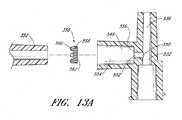
ここで図13A〜図13Bを参照すると、図13Aは、ターゲットコネクタ部338、ターゲットチェックバルブ358、および本体342の分解断面図である。図13Bは、ターゲットチェックバルブ358が開放ポジションにある組み立てられた構造体における、ターゲットコネクタ部338、ターゲットチェックバルブ358、および本体342の断面図である。本体342は、交差部550において第1の流体通路532と交差する第2の流体通路548を含むことができる。いくつかの実施形態において、第2の流体通路548は、第1の流体通路532の上部536と交差可能である。図示された実施形態において、第2の流体通路548は、実質的に直角で第1の流体通路532と交差する。他の構造を採用することも可能である。例えば流体通路532,548は、斜角(直角を除く鋭角または鈍角)で交差することもできる。第2の流体通路548は、ショルダ556を規定する幅狭部552と幅広部554とを有することができる。いくつかの実施形態において、幅狭部552は、第1の流体通路532の上部536のうちの交差部550付近の幅と実質的に同じ幅を有することができ、一方で他の実施形態においては、幅狭部552は、第1の流体通路532の上部536のうちの交差部550付近の幅より小さな幅またはより大きな幅を有することができる。いくつかの実施形態において、第2の流体通路548の幅狭部552および/または幅広部554は、テーパー形状の内面を有することができる。例えば幅広部554は、上述したように先細雄型コネクタ352を収容するために先細形状のものとすることができる。 Here, referring to FIGS. 13A to 13B, FIG. 13A is an exploded cross-sectional view of the
組み立て時に、ターゲットチェックバルブ358は、雄型コネクタ352とショルダ556との間に計請求項逸されたチャンバ354内に配置可能である。いくつかの実施形態において、ターゲットチェックバルブ358は、上記供給チェックバルブ356と同様のものとすることができ、ディスク形状基部558と複数の脚部560と封止面562とを含む。ターゲットチェックバルブ358は、脚部560が雄型コネクタ352に面しかつ封止面562がショルダ556に面する状態で配置可能である。したがって、第2の流体通路548内の圧力が雄型コネクタ352内の圧力よりも十分に高いものとなった場合に、例えばシリンジ318のプランジャ520が本体342内へ流体を押し出すよう前進させられた場合に、ターゲットチェックバルブ358は、脚部560が開放ポジションにおける雄型コネクタ352の端部に支持されるように、雄型コネクタ352へ向けて押圧され得る。第2の流体通路548内の圧力が雄型コネクタ352内の圧力より十分に低いものとなったとき、例えばシリンジ318のプランジャ520が本体342から流体を引き出すよう後退させられた場合に、チャンバ354から第2の流体チャネル548の幅狭部552へ流体が流動することを防止する液密封止部を形成するショルダ556と封止面562とが係合するように、ターゲットチェックバルブ358を本体342から引き離すことが可能となる。 Upon assembly, the
いくつかの実施形態において、ターゲットチェックバルブ358およびチャンバ354は、その開放ポジションにおいて流体がターゲットチェックバルブ358の周囲を流通する際のボトルネックを低減するよう構成できる。例えば、ターゲットチェックバルブ358およびチャンバ348は、上述されたターゲットチェックバルブ358およびチャンバ348は、と同様の方法で構成できる。 In some embodiments, the
チェックバルブ356,358は、システムを介して直接的に流通させるよう、ともに作動することができる。図14Aは、プランジャ520が後退させられた場合の流体の流通状態を(流動ラインによって)示す図である。流体は、流体抽出チャネル382の上部384を介して小型容器314から流出させられる。流体は、第1の流体通路532を通り、シリンジ318へ流入する。流体は、第2の流体通路548の幅狭部552へ入ることも可能だが、ターゲットチェックバルブ358が閉鎖ポジションにあるためチャンバ354への流体の流入は防止される。 Check
図14Bは、プランジャ520が前進させられた場合の流体の流通状態を(流動ラインによって)示す図である。流体は、シリンジ318から、第1の流体通路532へ、かつ、IVバッグ316へ向けて、ターゲットコネクタ部338を介して、(開放ポジションにある)ターゲットチェックバルブ358の周囲において、第2の流体通路548の幅狭部552を介して、チャンバ354へと押し出される。流体は、チャンバ348から第1の流体通路532へ移動可能であるが、供給チェックバルブ356は閉じられているため小型容器314内へ流体が進入することは防止される。いくつかの実施形態において、供給チェックバルブ356を流体が押す力は、供給チェックバルブ356を閉ポジションに維持するために、供給チェックバルブ356を下方へ引っ張る重力に打ち勝つ程度に十分強いものである。 FIG. 14B is a diagram (by a flow line) showing the fluid flow state when the
チェックバルブ356,358は、硬質な、またはある程度硬質な、もしくは変形可能な材料から形成することができる。いくつかの実施形態において、少なくともチェックバルブ356,358の封止面531,562は、プラスチックまたは他の硬質な材料に対して液密封止部を形成可能な材料から形成できる。いくつかの実施形態において、チェックバルブは、シリコン由来の変形可能な材料またはラバーを含むことができる。いくつかの実施形態において、脚部528,560は、ディスク形状基部526,558とは異なる材料から形成することができる。いくつかの実施形態においては、脚部528,560は、硬質なポリカーボネートまたは他のポリマー材料から形成可能である。Check valves 356,358 can be formed from a material that is hard, or somewhat hard, or deformable. In some embodiments, at least the sealing surfaces 531,562 of the check valves 356,358 can be formed from a material capable of forming a liquidtight seal with respect to plastic or other hard material. In some embodiments, the check valve can include a deformable material or rubber derived from silicon. In some embodiments, the legs 528,560 can be formed from a different material than the disc shape bases 526,558. In some embodiments, the legs 528,560 can be formed from hard polycarbonate or other polymeric material.
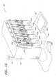
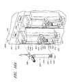
図15は、流体の移行のための自動化システム600の斜視図である。これは本明細書に開示された他の自動流体移行システム(例えば100,200)と同様のまたは同一のものとすることができる。システム600は、ベースハウジング602およびベースハウジング602の前側に配置された6つの移行ステーション604a〜fを含むことができる。いくつかの実施形態において、システム600は、異なる数の移行ステーション604a〜f(例えば1,2,4,5,8またはそれ以上の移行ステーション)を含むことができる。いくつかの実施形態において移行ステーション604a〜fは、ベースハウジング602の複数の側面に分散させることも可能である。図示された移行ステーション604a〜fは、それに取り付けられるシリンジが空の状態で示されている。移行ステーション604aは、それに取り付けられるシリンジ606およびコネクタ608を有した状態で示されている。操作中に、小型容器(図示せず)をコネクタ608の上部に取り付けることができ、かつ、上記のように流体が小型容器からシリンジ606へ、続いてシリンジ606からIVバッグへ移行させられるように、IVバッグ(図示せず)をコネクタ608と流体連通状態で配置することができる。また、操作中に、移行ステーション604a〜fのいくつかあるいはそのすべては、移行ステーション604aと同様に備えることができる。いくつかの実施形態において、複数の移行ステーション604a〜fを同時に操作することができる。いくつかの実施形態において、複数の移行ステーション604a〜fは、複数の小型容器からの流体が単一のIVバッグ内で混合されるように、単一のIVバッグと流体連通状態となるように配置することができる。いくつかの実施形態において、1つ以上の移行ステーション604a〜fは、専用のIVバッグを含むことができ、これにより、単一の移行ステーションのみからの流体が、上記専用のIVバッグへ移行可能となる。 FIG. 15 is a perspective view of the automation system 600 for fluid migration. This can be similar to or identical to other automated fluid transfer systems disclosed herein (eg, 100, 200). The system 600 can include a
ここで図16A〜図16Cおよび図17を参照すると、移行ステーション604がより詳細に示されている。図16Aは、非係合状態の、シリンジ606およびコネクタ608を備える移行ステーション604aを示す部分斜視図である。図16Bは、非係合状態の、シリンジ606およびコネクタ608を備える移行ステーション604aの左側面図である。図16Cは、図面から省略されたシリンジ606およびコネクタ608を備える移行ステーション604aの正面図である。移行ステーション604aは、ベースハウジング602に連結された軸線方向ハウジング610を含むことができる。移行ステーション604aは、軸線方向ハウジング610の上方においてベースハウジング602に取り付けられた上部連結部品612と、軸線方向ハウジング610の下方においてベースハウジング602に取り付けられた下部連結部品614と、を含むことができる。上部連結部品612および下部連結部品614は、軸線方向ハウジング610から距離をおいて外側へ延在でき、かつ一対のシャフト616a〜bは、上部連結部品612と下部連結部品614との間において垂直方向に延在することができる。シャフト616a〜bには中間連結部品618を取り付けることができる。 Here, with reference to FIGS. 16A-16C and 17, the transition station 604 is shown in more detail. FIG. 16A is a partial perspective view showing a
中間連結部品618は、シリンジ本体624を収容可能に構成された凹部620を有することができる。例えばシリンジ本体624が略円筒形状のものである場合、凹部620は(図示されるように)半円筒形状の形状を有することができる。中間連結部品618は、シリンジ6060の本体フランジ626を収容するよう構成されたスリット622を含むこともできる。上部連結部品612は、シリンジ606の遮壁630およびコネクタ608の一部を収容するよう構成された凹部628を有することができる。いくつかの実施形態において、中間連結部品618は取り外し可能であり、そのため、中間連結部品618は、さまざまなサイズおよび形状のシリンジとの補償性を提供するよう付加的な中間部品(図示せず)と相互交換可能である。また、いくつかの実施形態において、中間連結部品618のポジションは調節可能である。例えば中間連結部品618は、さまざまな長さのシリンジとの補償性を提供するために、シャフト616a〜bを上下にスライド可能でありかつさまざまな位置に固定できる。いくつかの実施形態において、中間連結部品618のポジションは固定することもできる。 The intermediate connecting
移行ステーション604aは、シリンジ606のプランジャ634を後退させかつ前進させるよう構成されたアクチュエータ632を含むことができる。2つのシャフト648a〜bは、アクチュエータベース636の後方に配置可能であり、かつアクチュエータベース636から軸線方向ハウジング610内へ上方に延在可能である。他のシャフト640をアクチュエータベース636の前方に配置することもでき、かつこれは軸線方向ハウジング610内へ前方において上方に延在可能である。端部部品642は、シリンジ606プランジャフランジ648を収容するよう構成された水平スリット644を含むことができる。また端部部品642は、プランジャフランジ648に近接するプランジャシャフト650の一部を収容するよう構成できる。例えばプランジャシャフト650が(図示されるように)4つの長手方向リブを含む場合、端部部品642は、長手方向リブのうちの1つを収容するよう構成された垂直スリット646を含むことができる。端部部品642は、また、プランジャフランジ648に圧力を付与するよう締め付け可能な、つまみねじ652を含むことができ、それによりシリンジ606が移行ステーション604aから偶然に脱落してしまうことが防止できる。 The
いくつかの実施形態において、軸線方向ハウジング610内にモータ(図示せず)が配置されている。モータは、電気モータ、空気式モータ、水力モータまたはアクチュエータ632を作動可能な他の適切なタイプのモータとすることができる。いくつかの実施形態においてモータはピストンタイプのモータであってもよい。いくつかの実施形態において、モータは、軸線方向ハウジング610内というより、むしろベースハウジング602内に収容されている。いくつかの実施形態において、各移行ステーション604a〜fは、個々の移行ステーション604a〜f専用のモータを有する。いくつかの実施形態において、1つ以上の移行ステーション604a〜fが1つのモータを共用しており、かついくつかの実施形態においては、システム600はすべての移行ステーション604a〜を駆動するために使用される単一のモータを含んでいる。モータは、軸線方向ハウジング610から下方においてシャフト638a〜bを駆動することができ、それはアクチュエータ632の他の部分を下方へ動作させ、流体がシリンジ内に引き込まれるようプランジャ634はシリンジ本体624から後退させられる。またモータは、シャフト638a〜bを軸線方向ハウジング610内へ上方へ引っ張ることができ、続いてアクチュエータ632の他の部分を上方へ駆動し、シリンジから流体を引き出すようプランジャ632がシリンジ本体624内へ前進させられる。 In some embodiments, a motor (not shown) is located within the
いくつかの実施形態において、移行ステーション604aは、特定の移行ステーション604aを独自に示すラベル654を含むことができる。いくつかの実施形態においてラベル654は、移行ステーション604aの上部に目立つように掲示され得る。ラベル654は着色可能であり、かつ各移行ステーション604a〜fは、さまざまに着色されたラベルを有することができる。 In some embodiments, the
システム600は、移行ステーション604a〜fの作動を制御するためにコントローラを含むことができる。コントローラは、各移行ステーション604a〜fにおいて小型容器からIVバッグへ移行させられる流体の量を制御するために、システム600のモータをスタートさせかつ停止させることができる。コントローラは、1つ以上のマイクロプロセッサまたは他のタイプの適切なコントローラとすることができる。コントローラは、一般的な用途のコンピュータプロセッサあるいはシステム600の機能を制御するよう特別に設計された特別な用途のプロセッサとすることができる。コントローラは、システム600の動作を制御するためのソフトウェアアルゴリズムを含むメモリモジュールを含む、あるいはメモリモジュールと通信できるものである。コントローラは、ベースハウジング602内に収容可能である。いくつかの実施形態において、コントローラは、ベースハウジング602の外側にあってもよく、かつ例えばシステム600の構成要素とワイヤによる通信もしくはワイヤレスの通信する一般的な用途のコンピュータのプロセッサとすることができる。 System 600 may include a controller to control the operation of
いくつかの実施形態において、移行ステーション604aは、(図16A〜図16Cでは隠れている)センサを含む。センサは、小型容器(図示せず)の中の流体が流出したことを検出するよう構成されている。小型容器がそれ以上流体を含むことができない場合にプランジャ634がシリンジ606へ流体を引き込むために後退させられると、空気が小型容器から引き出されてシリンジへ向けてコネクタ608内へ移動する。また空気は、小型容器がまだ少量の流体を含む場合にはコネクタ608へ引き込まれてもよいが、流体レベルは、空気が流体とともに(例えば気泡として)小型容器から引き出される程度に低いものとなる。いくつかの実施形態において、センサは、コネクタ608内の空気を検出できる。例えばセンサは、赤外線の光源(例えばLED)および光検出器または他のエレクトロニクス・アイとすることができる。 In some embodiments, the
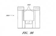
いくつかの実施形態において、センサは上部連結部品612の内側に配置することができる。上部連結部品612は、下部656および上部658から形成できる。図17は、上部658を除去された状態の上部連結部品612の下部656の斜視図である。下部656は、中央キャビティ660と、凹部628の両側にそれぞれ配置される一対の溝662a〜bとを含むことができる。溝662a〜bは、溝664a〜bを中央キャビティ660に接続可能である。いくつかの実施形態において、溝662a〜b、溝664a〜bは、半円形の断面積を有することができる。他の実施形態において、これら溝はV字形状のあるいは他の適切な形状の溝とすることができる。溝662a〜bは、凹部628に最も近接する端部において解放されていてもよい。いくつかの実施形態において、溝662a〜bと凹部628とを接続する孔666a〜bを壁665a〜bが有する場合を除いて、壁665a〜bが、凹部628から溝662a〜bを区分することができる。 In some embodiments, the sensor can be placed inside the
光源668を溝662a内に配置することができ、かつ光検出器670を溝662b内に配置することができる。いくつかの実施形態において、光源668は、光のレーザービームが孔666aを通り、凹部628を横断して、孔666bへ入り、光検出器670まで方向付けられるように整列されたレーザー光源とすることもできる。いくつかの実施形態において、光源668は、LEDまたは他のタイプの光源とすることができる。いくつかの実施形態において光源668は多くの方向に光を送出することができ、それにより、その光のいくつかは、孔666aを通り、凹部628を横断して、孔666bへ入り、光検出器670まで到達するようになる。ワイヤ672が、光源668に連結でき、かつ溝664aに沿ってかつ中央キャビティ660を通って延在することもできる。ワイヤ672は、コントローラから光源668へ電力または電気信号を提供することができる。ワイヤ674は、光検出器670に連結することもでき、かつ溝664bに沿ってかつ中央キャビティ660を通って延在することができる。ワイヤ674は、光検出器670からコントローラへ電気信号を伝送できる。 The
いくつかの実施形態において、上部連結部品612の上部658(図17には図示せず)は、下部連結部品656の溝および/またはキャビティに対応する溝および/またはキャビティを有することができる。いくつかの実施形態において、上部658は、下部656に形成される溝および/またはキャビティに対する蓋として機能するような、おおむね平坦な下面を有することができる。上部658は、接着剤、クランプ、スナップまたは摩擦嵌合構造、あるいは、公知のもしくはこのために考案されたさまざまな他の方法によって下部656に取り付けることができる。いくつかの実施形態において、上部658は、較正、修理または交換などのために使用者が光源668および光検出器670にアクセスできるように、下部656に取り外し可能に取り付けられている。 In some embodiments, the upper 658 of the upper connecting part 612 (not shown in FIG. 17) can have a groove and / or cavity corresponding to the groove and / or cavity of the lower connecting
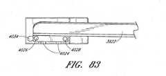
シリンジ606およびコネクタ608が移行ステーション604aに取り付けられた場合に、コネクタ608(図17には図示せず)を、光源668から光検出器670まで延在する光676の経路内に配置することができる。いくつかの実施形態において、コネクタ608の少なくとも一部が、実質的に透明なプラスチック、または光676がコネクタ608の壁を通過する可能にする他の適切な材料から形成できる。図18は、シリンジ606およびコネクタ608の側面図であり、かつコネクタ608における光676の交差位置を示す。いくつかの実施形態において、コネクタ608は、光676が供給コネクタ部677の下端部の下側であるがシリンジ606の雄型ルアー先端部678の上方の位置においてコネクタ698を通過するよう配置できる。この領域は図18において領域680として示されている。いくつかの実施形態において、コネクタ608は、光676がコネクタ608の外部ショルダ682の上方において(領域684として示される)コネクタ608を通過するよう配置されている。いくつかの実施形態において、コネクタ608は、光676が第2の流体通路688との接合点の上方の位置(領域690で示される)において第1の流体通路686を通過するよう配置できる。いくつかの実施形態において、光676は、供給コネクタ部677の下端部と接合部の上部との間の中間地点の付近においてコネクタ608を通過する。それにより、第2の流体通路688に流入する流体または第2の流体通路688から流出する流体として形成された乱流が、センサの読み取りにおいてエラーを引き起こすことがなくなる。いくつかの実施形態において、シリンジ606へ引き込まれる流体として空気が検出されたときに、空気が雄型ルアー先端部678に到達する前にその流れが止められるように、光676は、シリンジ606の雄型ルアー先端部678から十分に離れた位置に置いてコネクタ608を通過する。 When the
いくつかの実施形態において、光源668から光検出器670へ延びる光676のビームは、第1の流体通路686の幅全体を実質的にカバーする程度に大きなものである。それにより空気バブルが、光676のビームと交差せずにシリンジ606内に引き込まれるように移動することは不可能となる。いくつかの実施形態において、図17に示される孔666a〜bは図示されたものより大きくてもよく、あるいは孔666a〜bを、光が第1の流体通路686の幅全体と実質的に交差可能な水平スリットとすることができる。 In some embodiments, the beam of
光源668および光検出器670は、吸光分光法、発光分光法、散乱分光法、蛍光分光法、あるいは非開676のビームの経路内における空気の存在と流体の存在との違いを区別する他の適切な様式を使用して、空気が存在することを検出するよう構成できる。
図19Aは、上述した上部連結部品612にある程度関連して類似し得る上部コネクタ部品1900の他の実施形態の斜視図である。図19Bは、上部連結部品の分解図である。上部連結部品1900は、自動化された流体移行システム600と関連して上部連結部品612の代わりに使用することもできる。例えば、上部連結部品1900は、ベースハウジング602と連結可能であり、かつシリンジ606の一部またはコネクタ608の一部を収容するよう機能できる。 FIG. 19A is a perspective view of another embodiment of the
上部連結部品1900は、ベース部材1902と、カセット1904とを含むことができる。いくつかの実施形態において、ベース部材1902はアルミニウムなどの材料から形成できるが、他の材料を使用することも可能である。カセット1904は、カセット1904はプラスチックから形成できるが、他の材料を使用することも可能である。カセット1904は孔1908と整列されるよう構成された孔1906を含むことができ、ボルト、ねじまたは他の固定具を孔1906,1908に挿入することによってカセット1904をベース部材1902に固定できるようになる。いくつかの実施形態において、孔1906,1906の一方あるいはその両方が、ボルトまたは他の固定具におけるねじ切り部と対応してかみ合うように、ねじ切りされていてもよい。孔1906は、その中にボルトのヘッドを収容するように広げられた上側部分を含むことができる。またカセット1904は、スナップ留め、摩擦嵌合あるいは他の適切な様式によってベース部材1902と固定可能である。 The upper connecting
ベース部材1902は、カセットの上面がベース部材1902の上面と実質的に平坦となるように整列されるように、カセット1904を収容するよう構成された切欠き領域1910を含むことができる。1つ以上の孔1912a〜cがベース部材1902の背面から切欠き領域1910まで延在することができる。この実施形態において3つ以上の孔1912a〜cが図示されているが、他の数の孔をしようすることもできることを理解されたい。外側孔1912a,1912cは、ピン、または、ベース部材1902を流体移行システム600のハウジング602へ固定するために使用される他の固定具を収容可能である。内側孔1912bは、ワイヤ1914a〜b,1916a〜bが切欠き領域1910からベース部材1902を通ってハウジング602へ通過可能なチャネルを提供することができる。多くの他の構成を採用することもできる。例えば、ベース部材1902をハウジング602に固定するためにかつワイヤ1914a〜b,1916a〜bのためのチャネルを提供するために、単一の孔を使用することも可能である。 The
上部連結部品1900の内側に第1の光源1918aおよび対応する第1の光検出器1920aを配置することができる。第1の光源1918aおよび第1の光検出器1920aは、上記光源668および760と同様のものであってもよい。図19Bにおいて第1の光源1918aおよび第1の光検出器1920aは切欠き領域1910内に配置されているが、第1の光源1918aおよび第1の光検出器1920aはカセット1904内に形成されたスロット1922a〜bの内側に配置することもできる。第1の光源1918aは、光1924を、カセット1902内に形成された孔1926aを介して、凹部1928aを通し、凹部1928aの他側におけるカセット1902内に形成された第2の孔1926bを介して、そして第1の光検出器1920aへと方向付けるよう構成できる。ワイヤ1914aは、電力または他の電気信号をコントローラから第1の光源1918aまで提供できる。ワイヤ1916aは、第1の光検出器1920aからコントローラまで電気信号を伝送できる。 A first light source 1918a and a corresponding
第1の光源1918aおよび第1の光検出器1920aは、上記光源668および光検出器760と同様にコネクタ608内の空気を検出するよう構成できる。凹部1928a,1928bは、(例えば図18に関連して上述したように)光1934が小型容器とシリンジ606との間の流体通路の一部を通過するようコネクタ608の透明部分が光1924の経路内に配置されるように、シリンジ606および/またはコネクタ608を収容可能なように構成できる。第1の光源1918aおよび第1の光検出器1920aは、
流体通路内の空気を検出し、かつ小型容器が交換必要であることを示すようにコントローラに信号を提供するよう構成できる。The first light source 1918a and the
It can be configured to detect air in the fluid passage and signal the controller to indicate that the small vessel needs to be replaced.
カセットによって形成された凹部1928aの一部は、それと係合するよう構成されたコネクタ608の一部と適合するように、実質的に半円形状のものとすることができる。ベース部材1902によって形成された凹部1928abの一部は、凹部1928aのうちのカセットによって形成された部分に対して、ステップ1920が凹部1928bの両側に形成されるようにさらに囲われるようになっている。ステップ1930は、コネクタ608と上部連結部品1900との適切な固定および整列を容易にすることができる。 A portion of the
上部連結部品1900の内側に第2の光源1918bおよび対応する第2の光検出器1920bを配置することができる。第2の光源1918bおよび第2の光検出器1920bは、上記光源668および760と同様のものであってもよい。図19Bにおいて第2の光源1918bおよび第2の光検出器1920bは切欠き領域1910内に配置されているが、第2の光源1918bおよび第2の光検出器1920bはカセット1904内に形成されたスロット1922a〜bの内側に配置することもできる。カセット1904は、外側に延在する一対のアーム1934a〜bを有することができ、かつスロット1922a〜bがアーム1934a〜bに沿って延在することができる。ベース部材1902は、カセット1904のアーム1934a〜bの下方に配置された対応するアーム1936a〜bを有することができる。第2の光源1918bは、光1938を、カセット1902の第1のアーム1934aに形成された孔1932aを介して、アーム1934a〜bの間に計晴雨されたギャップを通し、カセット1902の第2のアーム1934bに形成された第2の孔1932bを介して、そして第2の光検出器1920bへと方向付けるよう構成できる。ワイヤ1914bは、電力または他の電気信号をコントローラから第2の光源1918bまで提供できる。ワイヤ1916bは、第2の光検出器1920bからコントローラまで伝送することができる。 A second
いくつかの実施形態において、カセット1904は、光源1918a〜b、光検出器1920a〜bおよびワイヤ1914a〜b、1916a〜bへの修理または交換のためのアクセスを提供するよう、ベース部材1902から取り外し可能である。いくつかの実施形態において、光源1918a〜bおよび/または光検出器a〜bは、カセット1904に固定可能であり、かつカセット1904は、光源1918a〜bまたは光検出器1920a〜bが破損した場合にもしくは他の機能性(例えば異なる波長の光)が所望された場合に交換カセットと交換可能である。 In some embodiments, the
第2の光源1928bおよび第2の光検出器1920bは、IVバッグアセンブリがコネクタ608に接続されているかどうかを検出するよう構成できる。いくつかの実施形態において、コントローラは、
IVバッグが特定の移行ステーションに取り付けられていないとコントローラが判断した場合に、使用者からの、特定の移行ステーションのためにIVバッグへ流体を移行させるとの指示を中断させるよう構成できる。それにより、移行さえられる流体の無駄遣いが防止され、かつ潜在的に危険な流体の露出が防止される。指示がこの様式によって中断された場合に、コントローラはユーザーインターフェース上にエラーメッセージまたは警告を表示することもできる。いくつかの実施形態において、IVバッグアセンブリが取り付けられていない場合にコネクタ608の一部(例えばターゲットコネクタ部338)を閉じることができ、それにより、コネクタはIVバッグアセンブリが取り付けられていない場合に流体が流出することを防止できることを理解されたい。ただし、流体移行システムが閉じられたコネクタへ流体を注入することを許可した場合、コネクタ内に高い圧力をもたらすことがあり、それは、流体が流出することを可能にしてコネクタの閉鎖封止部を損なうか、あるいはシステム600に対して損傷をもたらすことがある。第2の光源1918bおよび第2の光検出部1920bは、IVバッグアセンブリがコネクタ608に取り付けられているかどうかを検出するよう構成されたセンサの一例であり、IVバッグアセンブリの存在を検出するための他のタイプのセンサも使用できることを理解されたい。The second
If the controller determines that the IV bag is not attached to a particular migration station, it can be configured to interrupt the user's instruction to transfer fluid to the IV bag for a particular migration station. This prevents the waste of fluids that are even transferred and prevents the exposure of potentially dangerous fluids. The controller may also display an error message or warning on the user interface if the instruction is interrupted by this form. In some embodiments, a portion of the connector 608 (eg, target connector portion 338) can be closed when the IV bag assembly is not attached, thereby allowing the connector to be attached when the IV bag assembly is not attached. It should be understood that the outflow of fluid can be prevented. However, if the fluid transfer system allows fluid to be injected into the closed connector, it can result in high pressure inside the connector, which allows the fluid to flow out and closes the connector. It can be detrimental or damage the system 600. The second
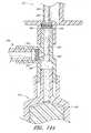
第2の光源1918bおよび第2の光検出部1920bがIVバッグアセンブリの存在を検出する様式について図19C〜図19に関連して説明する。図19Cは、コネクタ320または本明細書に記載された他のコネクタと同様のコネクタ1950の側面図である。コネクタ1950は、供給コネクタ部1952とターゲットコネクタ部1954とを含むことができる。図示された実施形態において、供給コネクタ部1952およびターゲットコネクタ部1954は本体部品1956に取り付けることができる。本体部品1956は、シリンジまたは他の中間測定容器を収容するよう構成された中間コネクタ部1958を有することができる。 The mode in which the second
図19Dは、閉状態にあるターゲットコネクタ部1954を示す、コネクタ1950の断面図である。図19Eは、開状態にあるターゲットコネクタ部1954を示す、コネクタ1950の断面図である。ターゲットコネクタ部1954は、本明細書に開示されたターゲットコネクタ部338と同様のものとすることができる。ターゲットコネクタ部1954は、ハウジング1960と、細長プランジャ1964を含む端部キャップ1962とを有することができる。図19Dに示されるようにバルブが閉ポジションにあるときに、プランジャ1964の少なくとも一部が露出されたまま、バルブ部材1966のベース1968がプランジャ1964の端部のみと重なるように、バルブ部材1966はプランジャ1964にスライド可能に係合できる。IVバッグアセンブリのコネクタ1965が(例えば図6D〜Eに関連して上述されたように)ターゲットコネクタ部1954に取り付けられているとき、バルブ部材1966は、図19Eに示されるように端部キャップ1962へ向けて変位させられる。 FIG. 19D is a cross-sectional view of the
第2の光源1918bおよび第2の光検出器1920bが図19D〜図19Eに概略的に示されている。いくつかの実施形態において、ハウジング1960の少なくとも一部およびプランジャ1964の少なくとも一部は、第2の光源1918bによって放出された光1938を透過する材料から形成できる一方で、バルブ部材1966は、光1938を透過させない材料、あるいは他の方法で光1938の経路内に配置されたときに第2の光検出器1920bに光1938が到達することを防止する材料から形成できる。したがって、IVバッグアセンブリがコネクタ1950に取り付けられておらずかつターゲットコネクタ部1954が(図19Dに示されるように)閉構造となっている場合において、光1938は、透明ハウジング1960を通過し、透明プランジャ1964をとおり、第2の光検出器1920bまで通ることができる。第2の光検出器1920bが光1938を検出したときに、IVバッグアセンブリがターゲットコネクタ部1954に取り付けられていないことを示す信号をシステムコントローラに伝送できる。IVバッグアセンブリがターゲットコネクタ部1954に取り付けられている場合、バルブ部材1966のベース1958は、図19Eに示されるように、光1938の経路と交差できかつ第2の光検出器1920bに光1938が到達することを防止できる。第2の光検出器1920bが光1938を検出しない場合、第2の光検出器1920bは、ターゲットコネクタ部1954が開構造状態にありかつIVバッグアセンブリがそれに取り付けられていることを示す信号をシステムコントローラに伝送できる。 A second
いくつかの実施形態において、コネクタ1950は、光1938がプランジャ1964と交差することなくプランジャ1964に隣接する解放空間1970を通過するよう整列可能である。したがって、いくつかの実施形態において、プランジャ1964は、光1938を透過しない材料から形成できる。図19Eに示されるような開構造において、バルブ部材1966のベース1968は、光1938を遮断するようプランジャ1964に隣接する空間1970を満たす。したがって、いくつかの実施形態において、光1938は、ターゲットコネクタ部1954を通して形成された流体流通経路1972と通過しない。これは、光1938が第2の光検出器1290bに到達することを防止し得るコネクタを介して流体が移行させられる際などの特定の状況において、利点となり得る。 In some embodiments, the
また、図19D〜図19Eには、上記のように、第1の光源1918aによって射出され、小型容器とシリンジとの間に形成された流体流通経路1974を経て第1の光検出器1920aまで送出される光1294を示す。 Further, in FIGS. 19D to 19E, as described above, the light is emitted by the first light source 1918a and sent to the
ここで図15に戻るが、システム600は、使用者からの情報および指示を受け取るためのかつ使用者へ情報を提供するためのユーザーインターフェース692を含むことができる。ユーザーインターフェース692は、外部ユニット694の一部とするか、あるいはベースハウジング602と一体化してもしくはそれに取り付けることができる。ユーザーインターフェース692は、例えば、タッチスクリーンディスプレイを含むことができる。ユーザーインターフェース692は、コントローラとワイヤ通信もしくはワイヤレス通信できる。いくつかの実施形態において、ケーブル696が、ベースハウジング602に外部ユニット694を接続し、かつユーザーインターフェース692とコントローラとの間の通信リンクを提供する。いくつかの実施形態において、コントローラは、ユーザーインターフェース692とともに外部ユニット694に含まれることができ、かつコントローラは、ケーブル696を解してシステム600の構成要素(例えばモータ)へ信号を伝送しかつそれから信号を受け取ることができる。ユーザーインターフェース692は、移行ステーション602a〜fによって移行される流体の量に関連した使用者からの指示を受け取るよう構成できる。ユーザーインターフェース692は、メモリに蓄積させられかつ/または所望の量の流体を移行するべくモータを作動させるために使用される指示をコントローラへ伝送可能である。Returning to FIG. 15, the system 600 can include a
いくつかの実施形態において、システム600は、(図15においてアンテナ691として概略的に図示される)通信インターフェースを含むことができる。通信インターフェース691は、コントローラと遠隔の供給源(遠隔ターミナルまたは自動管理システムなど)との間に通信リンクを提供するよう構成できる。通信リンクは、ワイヤレス信号、またはケーブルあるいは2つの組み合わせによって提供できる。通信リンクは、WAN、LANまたはインターネットなどのネットワークを使用できる。いくつかの実施形態において、通信インターフェースは、遠隔供給源からの入力(例えば流体移行指示)を受け取るよう構成でき、かつコントローラから遠隔供給源へ情報(例えば結果または警告)を提供することができる。いくつかの実施形態において、遠隔供給源は、複数の自動化された流体移行システム(例えば100,200および600)間で同等の動作が可能な自動化された管理システムとすることができる。 In some embodiments, the system 600 can include a communication interface (schematically illustrated as
システム600は、コントローラおよび/またはメモリと通信するバーコードスキャナ698を含むこともできる。バーコードスキャナ698は、システム600に関する情報をコントローラおよび/またはメモリへ提供するために使用できる。例えば、シリンジ606は、シリンジの606のサイズおよびタイプを識別するバーコードを含むことができる。使用者は、シリンジ606をバーコードスキャナ698でスキャンでき、それにより、移行ステーション604aに取り付けられたシリンジ606のサイズをコントローラへ通知するために行こうステーション604aと関連付けられたバーコードをスキャンできる。さまざまなサイズのシリンダは、そのプランジャが同じ距離だけ引きだされた場合に、異なる量の流体を保持することができる。したがって、コントローラが所定の量の流体でシリンジ606を充填するよう使用されるとき、コントローラは、特定のタイプのシリンジに所定の量の流体を充填するために、プランジャをどの程度引き出すかを決定できる。小型容器(図示せず)は、その中に収容された流体のタイプを示すバーコードを含むことができる。使用者は小型容器をスキャンでき、それにより、小型容器が設置される特定の移行ステーションに関連付けられたバーコードをスキャンすることができる。したがって、コントローラは、流体の自動化された移行を容易にするために、どんな流体が移行ステーションによって制御されているかを認識することができる。システム600の他の構成要素も、その構成要素に関する情報をコントローラおよび/またはメモリに提供するために、バーコードスキャナ698によって読み取ることができるバーコードを含むことができる。いくつかの実施形態において、ユーザーインターフェース692は、バーコードスキャナ698を使用する代わりに、シリンジ606のサイズ、小型容器内に収容されている流体の種類などに関するデータを使用者が入力できるよう構成できる。 The system 600 can also include a barcode scanner 698 that communicates with the controller and / or memory. The barcode scanner 698 can be used to provide information about the system 600 to the controller and / or memory. For example, the
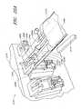
図20は、自動化された流体移行システム2000の他の実施形態を概略的に示す斜視図である。自動化された流体移行システム2000のいくつかの態様は、上記他の自動流体移行システム(例えば100,200または600)と同様のものであるか、または同じものとすることができる。自動流体移行システム600は、ベースハウジング2002と、6つの移行ステーション2004a〜fとを含むことができる(なお、システム600は、他の数の移行ステーションを含むこともできる)。図20では移行ステーション2004a〜fはボックスとして概略的に示されているが、各移行ステーション2004a〜fが移行ステーション604aに関連して上述されたものと同様のあるいは同じ構造体を含むことができることを理解されたい。例えば各移行ステーションは、小型容器、シリンジ、およびIVバッグアセンブリを含む流体移行サブシステム(例えばサブシステム300または1900)を含むことができる。 FIG. 20 is a perspective view schematically showing another embodiment of the automated
自動化された流体移行システム2000は、支持バーアセンブリ2050を含むことができる。図21は支持バーアセンブリの一部を概略的に示す側面図である。図20および図21を参照すると、支持バーアセンブリ2050は、両側においてアーム2054によって支持されている実質的な水平支持バー2052を含むことができる。各アーム2054は、取り付け部品2056によってベースハウジング2002の側面に取り付けることができる。いくつかの実施形態において、取り付け部品は、ベースハウジング2002と一体的に形成でき、あるいは例えば接着剤もしくは1つ以上のねじ2055または他の固定具によってベースハウジング2002に固定することができる。アーム2054は、アーム2054がショルダーボルト2058において枢軸回動可能なように、ショルダーボルト2058によって取付部品2056に取り付けることができる。アーム2054の回転範囲は、上側ダウエルピン2060および下側ダウエルピン2062によって制限されてもよい。スプリングプランジャ2064は、アーム2054上に配置でき、かつアーム2054をロックして支持バー2052を適所に保持するために1つ以上のロッキングホール(図20および図21では隠れている)へスライドするよう構成できる。スプリングプランジャ1064は、アーム2054をロッキングポジションから解放するためにロッキングホールから引き出すこともできる。図20および図21において、アーム2054および支持バー2052は、アーム2054が上部ダウエル2060に隣接して配置され、上方ポジションに固定された状態で示されている。支持バー2052は、流体移行ステーション2004a〜fの1つ以上の流体移行サブシステムの少なくとも一部を保持するか、または他の方法で支持するよう構成できる。例えば、上方ポジションにロックされている場合、支持バー2052は、コネクタ上における応力の大きさを低減するべく、ターゲットコネクタ部、ターゲットコネクタ部に取り付けられた雌型コネクタ、IVバッグ、またはIVバッグアセンブリの他の部分を支持バー2052上に載置できるように配置することができる。 The automated
図22は、いくつかは本明細書に開示された他の自動流体移行システム(例えば100,200,600または2000)と同じかまたは同一の自動流体移行システム2200の他の実施形態を概略的に示す部分斜視図である。いくつかの実施形態において、1つ以上の移行ステーション(例えば2204a)は支持アーム2250を含むことができる。支持アーム2250は、上部連結部品2212と一体化して形成されるか、あるいはそれに取り付けることができる。代替的には、支持アーム2250は、上部コネクタ部品2212から分離可能であり、かつ例えば1つ以上のねじまたは他の固定具によってベースハウジング2202に直接固定できる。いくつかの実施形態において、支持アーム2250は、細長延在部2252および支持プラットフォーム2254を有する実質的に「L」字形状を有することができる。支持プラットフォーム2254は、流体移行ステーション2204aの流体移行サブシステムの少なくとも一部を保持するかまたは他の方法で支持するよう構成できる。例えば、支持プラットフォーム2254は、コネクタにおける応力の大きさを低減させるために、ターゲットコネクタ部2236、ターゲットコネクタ部2236に取り付けられた雌型コネクタ(図22には図示せず)、IVバッグ(図22には図示せず)またはIVバッグアセンブリの他の部分を支持プラットフォーム2254上に載置可能なように配置することができる。 FIG. 22 schematically illustrates other embodiments of the automatic
いくつかの実施形態において、支持アーム2250は、重量センサ、またはIVバッグアセンブリ(図22には図示せず)がターゲットコネクタ部2236に取り付けられているかどうかを判断できる他のタイプのセンサを含むことができる。例えば、重量センサ2256は、支持アーム2250がIVバッグに対する支持を提供する場合にIVバッグの重量を「感知」できる。重量センサ2256は、流体がIVバッグへ移行させられる前にIVバッグアセンブリがターゲットコネクタ部2236に取り付けられているかをコントローラが確認できるように、コントローラと電気通信可能である。 In some embodiments, the
いくつかの実施形態において、重量センサ2256は、正しい量の流体がIVバッグへ移送されたかどうかを確認するために使用できる。コントローラは、使用者から受信した指示から、ならびに、メモリ内に蓄積された情報(例えば移行させられる流体の量、移行させられる流体の密度、空のIVバッグの初期重量など)から、IVバッグの予想される重量を計算するよう構成できる。一度、流体の移行が完了すると、コントローラは、重量センサと使用してIVバッグの最終重量を測定でき、かつ、予想される重量と最終重量とを比較できる。最終重量が、(例えば重量センサの精度によって規定される)受け入れ可能な許容値以上に予想される重量と異なる場合、コントローラは、流体移行中において生じ得るエラー(例えば誤ったタイプの流体が移行されるか、誤った量の流体が移行される)を使用者に通知するよう、ユーザーインターフェースにエラーメッセージまたは警告を伝送できる。 In some embodiments, the
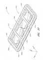
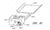
図22Aは、いくつかは本明細書に開示された他の自動流体移行システム(例えば100,200,600,2000および2200)と同じかまたは同一の自動流体移行システム2270の他の実施形態を概略的に示す部分斜視図である。システム2270は、ハウジング2274から外側に延在するトレイ2272を含むことができる。トレイ2272は、IVバッグ2276を支持するよう構成できる。トレイ2272は、平坦なベース2278と、IVバッグ2276がトレイ2272の側面から滑り落ちることを防止するために(約30°から60°で)上方を向く側面2280a〜bとを有することができる。ハウジング2274から最も遠位に位置するトレイ2272の端部2282は開放されていてもよく、上向きの側面を有していない。それによりIVバッグは、トレイ2272の端部を越えて吊り下げられることが可能となる。IVバッグ2276の重量を受けた状態でシステム2270が前方に傾くことを防止するために、ハウジング2274のベースから支持脚部2279が延在可能である。 FIG. 22A outlines other embodiments of the automatic
トレイ2272は、コネクタのターゲットコネクタ部2286と整列されるよう構成された孔または切欠き2284を含むことができる(それは、本明細書に開示されたコネクタ320または他のコネクタと同様のものとすることができる)。いくつかの実施形態において、ターゲットコネクタ部2286の外側ハウジング22288は、IVバッグアセンブリのコネクタ2290(これは雌型コネクタ322と同様のものとすることができる)に対して回転可能である。ターゲットコネクタ部2286の少なくとも一部が回転可能であるため、コネクタ2290は、ターゲットコネクタ部2286に脱着されるときに回転されることを必要としない。そのためチューブ2292はねじれたり巻きついたりせず、かつIVバッグアセンブリ2276をねじることが必要ではなくなる。いくつかの実施形態においてターゲットコネクタ部2286は、図6D〜図6Eに関連して上述した様式と同様の様式でコネクタ2290に係合するよう回転できるが、他の回転コネクタを使用できることを理解されたい。トレイ2272に形成された孔または切欠き2284は、ターゲットコネクタ部2286のハウジング2288の回転時に使用者の手が通過できるように構成できる。
トレイ2272はハウジング2274に取り外し可能に固定できる。いくつかの実施形態において、トレイ2272は、ボルト留め、ねじ留め、または他の方法でハウジング2274に固定可能である。スナップ嵌合連結または摩擦嵌合連結を用いることもできる。いくつかの実施形態において、トレイの端部は、上部連結部品2294と。トレイ2272ともに組み込まれる移行ステーションの軸線方向ハウジング2296との間に係合可能である。図22Aに示された実施形態は、システム2270の移行ステーションに取り付けられた単一のトレイ2272を示すが、それぞれのトレイが移行ステーションのうちの1つに組み込まれるように複数の個別のトレイも使用できることを理解されたい。いくつかの実施形態においては1つまたはすべての移行ステーションのために単一のトレイを使用できる。 The
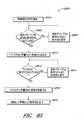
図23は、自動流体移行システム(例えば100,200,600,2000または2200)のための操作の方法2300を概略的に示すフローチャートである。ブロック2302において、システムは流体移行指示を受け取る。流体移行指示は、例えばユーザーインターゲースを介して使用者によって提供されるインプットから、または通信インターフェースを介して遠隔ターミナルまたは自動管理システムから受け取ることができる。流体移行指示は、移行される流体のタイプ、移行される流体の量、および所望の流体の濃度などの情報を含むことができる。いくつかの実施形態において、流体移行指示は、例えば複合混合物となるように混合される複数の流体の情報を含むことができる。 FIG. 23 is a flowchart schematically showing a method of
ブロック2304において、コントローラは、システムの流体移行ステーションが、現在、所望の流体を行こうするために備えられているかどうかを判断する。いくつかの実施形態において、システムは、コントローラが各移行ステーションと関連付けられた流体のタイプを特定できるように例えばデータベースまたはルックアップテーブルを含むメモリを含む。もし流体移行ステーションが特定の流体を有していない場合、この方法は、ユーザーインターフェースが1つまたは複数の流体移行ステーションを変更するよう使用者に促すブロック2306へ進むことができる。いくつかの実施形態において、コントローラは、(例えばメモリに蓄積された使用履歴を用いて)交換することが望まれる流体を特定でき、かつユーザーインターフェースを介して使用者に提案することができる。使用者が1つ以上の流体移行ステーションを変更した後、方法2300は、1つ以上の移行ステーションが適切に備えられているかを確認するブロック2304まで戻ることができる。 At
いくつかの実施形態において、使用者は、流体の移行のために使用すべく、所望の流体のタイプを特定するのではなく、1つ以上の移行ステーションを特定することができる。そのため、いくつかの実施形態において、ブロック2304およびブロック2306は省略可能である。いくつかの実施形態においてユーザーインターフェースは、流体移行のために使用される移行ステーションの選択時に使用者の助けとなるよう、さまざまな移行ステーションに関連付けられた流体のタイプを使用者に向けて表示することができる。 In some embodiments, the user can identify one or more migration stations for use for fluid migration, rather than identifying the desired fluid type. Therefore, in some embodiments,
いくつかの実施形態においてシステムは供給容器内に濃縮された流体を含むことができ、かつ、いくつかの状況において流体は患者に供給される前に希釈剤で希釈される。したがって、いくつかの場合において、コントローラは、供給容器内の流体の濃縮度に応じた希釈剤の所望量、所望濃度および移行される流体の量を特定できる。ユーザーインターフェースは、IVバッグに所望量の希釈剤を充填するよう使用者に促すことができる。あるいはシステムの1つ以上の移行ステーションが複数の希釈剤を含むことができる。したがって、いくつかの実施形態において、コントローラは、移行ステーションが所望の薬剤および所望の希釈剤を備えているかどうかを判断するようになる。 In some embodiments the system can contain a concentrated fluid in the feed vessel, and in some situations the fluid is diluted with a diluent before being fed to the patient. Thus, in some cases, the controller can identify the desired amount, desired concentration and amount of fluid to be transferred, depending on the concentration of fluid in the supply vessel. The user interface can prompt the user to fill the IV bag with the desired amount of diluent. Alternatively, one or more migration stations of the system can contain multiple diluents. Therefore, in some embodiments, the controller will determine whether the transition station is equipped with the desired drug and the desired diluent.
流体移行ステーションが適切に装着された場合、方法2300は、IVバッグが適切に取り付けられているかどうかをコントローラが特定するブロック2308へ進むことができる。いくつかの実施形態において、システムは、例えば移行ステーションのためのターゲットコネクタ部がIVバッグアセンブリに接続されているかどうかを特定可能な重量センサまたはIRセンサを含むことができる。いくつかの実施形態において、重量センサおよびコントローラは、IVバッグに所望の量の希釈剤が充填されているかどうかを特定できる。いくつかの実施形態において、メモリは、移行ステーションがIVバッグと関連付けられたことを示すデータベースまたはルックアップテーブルを含むことができる(これは、複数の移行ステーションが単一のIVバッグを関連付けられたときに特に有用となる)。この情報は、ユーザーインターフェースを介して使用者によって、またはIVバッグおよび移行ステーションにおけるバーコードをスキャニングすることによって入力可能である。IVバッグアセンブリが適切に取り付けられていない(例えばIVバッグが取り付けられていない、所望の希釈剤に関してIVバッグの重量が正しくない、またはIVバッグと関連づけられた移行ステーションの組み合わせが誤っている)ことをコントローラが特定した場合、ユーザーインターフェースは、IVバッグを取り付けるように、または他の方法でIVバッグ構造を変更するように使用者に促すことができる。使用者が変更を行うと、処理2300は、IVバッグアセンブリが適切に取り付けられかつ構成されていることを確認するために、ブロック2308へ戻ることができる。 If the fluid transfer station is properly fitted,
IVバッグアセンブリが適切に取り付けられている場合、処理2300は、以下に詳述するようにシステムが1つまたは複数の移行ステーションからIVバッグへの1つまたは複数の流体を移行させるブロック2312へ進む。 If the IV bag assembly is properly installed,
図24は、小型容器からIVバッグへ所定量の流体を移行させるための方法2400の一実施形態を概略的に示すフローチャートである。ブロック2402において、コントローラは、移行される流体の量を決定する。いくつかの実施形態において、その量は、流体移行指示によって直接的に特定できる。いくつかの実施形態において、流体(例えば薬剤または希釈剤)の量は、所望の濃度および小型容器内に収容される流体の濃度によって変更され得る。 FIG. 24 is a flowchart schematically showing an embodiment of
ブロック2404において、コントローラは、移行量が、移行ステーションに関連付けられたシリンダの有効最大容量よりも大きくなるよう決定する。いくつかの実施形態において、メモリは、さまざまな移行ステーションに関連づけられたシリンジのサイズを蓄積したデータベースまたはルックアップテーブルを含むことができる。この情報は、ユーザーインターフェースを介した使用者によって、あるいはシリンジおよび移行ステーションにおけるバーコードをスキャニングすることによって入力可能である。いくつかの実施形態において、シリンジの有効最大容量は、プランジャが実質的に完全に引きだされた場合のシリンジの容積である。いくつかの実施形態において、シリンジの有効最大容量は、アクチュエータが引き出し可能な最大量までプランジャが引きだされた場合のシリンジの容積である。 At block 2404, the controller determines that the migration amount is greater than the effective maximum capacity of the cylinder associated with the migration station. In some embodiments, the memory can include a database or look-up table accumulating syringe sizes associated with various migration stations. This information can be entered by the user through the user interface or by scanning the barcode at the syringe and transition station. In some embodiments, the maximum effective volume of the syringe is the volume of the syringe when the plunger is substantially fully retracted. In some embodiments, the effective maximum capacity of the syringe is the volume of the syringe when the plunger is withdrawn to the maximum amount that the actuator can withdraw.
移行される量がシリンジの有効最大容量よりも大きい場合、方法2400は、コントローラが、有効最大量の流体が小型容器からシリンジまで引き出されるようにシリンジのプランジャが引き出されるようにするブロック2406へ進む。ブロック2406において流体がシリンジへ移行されると、ブロック2408においてシステムは気泡に関するモニターを開始でき、それは、小型容器内の流体が流動することを示し得る。もしブロック2408において気泡が検出されると、方法2400は、ブロック2406を中断でき、かつブロック2410において空の小型容器を交換するよう使用者に促すことができる。一度小型容器が交換されると、方法2400はブロック2406まで戻り、そしてシリンジの充填を完了させることができる。 If the amount transferred is greater than the effective maximum capacity of the syringe,
一度シリンジが充填されると、この方法は、IVバッグが関連する移行ステーションのターゲットコネクタ部に取り付けられているかどうかをシステムが検出するブロック2412へ進むことができる。いくつかの実施形態において、重量センサまたはIRセンサは、ターゲットコネクタ部に取り付けられたIVバッグまたはコネクタの存在を検出するよう使用できる。IVバッグは流体移行中のミスにより分離する可能性があるため、いくつかの実施形態において、このシステムは、シリンジから流体を流動させるためシリンジのプランジャが前進させられるたびに連結されたIVバッグに関するチェックを行うよう構成できる。いくつかの実施形態において、システムは、流体移行の開始時においてのみ、取り付けられたIVバッグをチェックすることができ、そのためブロック2412および2414が省略される。IVバッグが取り付けられていない場合、方法2400は、IVバッグを最取り付けするようユーザーインターフェースが使用者に促すことができるブロック2414へ進むことができる。いくつかの実施形態において、UIは、エラーが生じ得る可能性(例えばIVバッグの早すぎる取り外しなど)があることを示す警告メッセージを使用者に提供できる。一度変更が行われると、方法2400は、IVバッグが適切に取り付けられたことを確認するべくブロック2412へ戻ることができる。いくつかの実施形態において、IVバッグが適切に取り付けられていない場合には、方法2400は、ブロック2414へ進まずに流体の移行を中断し、かつ使用者にエラーメッセージまたは警告を表示できる。 Once the syringe is filled, the method can proceed to block 2412, where the system detects if the IV bag is attached to the target connector portion of the associated transition station. In some embodiments, the weight sensor or IR sensor can be used to detect the presence of an IV bag or connector attached to the target connector section. In some embodiments, the system relates to an IV bag coupled each time the syringe plunger is advanced to allow fluid to flow from the syringe, as the IV bag can separate due to mistakes during fluid transfer. Can be configured to check. In some embodiments, the system can check the attached IV bag only at the beginning of the fluid transition, so that
一度、IVバッグが取り付けられていることをシステムが特定すると、方法2400は、コントローラが、シリンジからIVバッグへ流体を流動させるためにアクチュエータがシリンジのプランジャを前進させるようにするブロック2416へ進むことができる。ブロック2418において、この方法は、移行される流体の所定量からシリンジの有効最大容量(つまりブロック2416においてIVバッグへ加えられる所定量)を引くことができる。続いて方法2400はブロック2404へ戻ることができる。 Once the system identifies that the IV bag is installed,
ブロック2404において、移行される流体の量がシリンジの有効最大容量よりも少ないとコントローラが判断した場合、方法2400は、コントローラが、残りの流体の移行量をシリンジへ引き込む距離までシリンジのプランジャを引き出すブロック2420へ進むことができる。コントローラは、シリンジのサイズによって、移行されるべき残りの流体の量に基づいてプランジャを引き出すための距離を特定するよう構成でき、それはメモリ内のデータベースまたはルックアップテーブルに蓄積可能である。 If at block 2404 the controller determines that the amount of fluid transferred is less than the maximum effective capacity of the syringe,
ブロック2422において、システムは、ブロック2408と同様に気泡をモニターすることができる。気泡が検出されると、処理2400は、ブロック2420を中断でき、かつユーザーインターフェースが使用者に空の小型容器を交換するよう促すことができるブロック2424へ進むことができる。一度小型容器が交換されると、方法2400は、ブロック2420へ戻り、かつシリンジを所望の量の流体を充填することを完了できる。 At
一度シリンジが移行される残りの流体を含むと、この処理は、ブロック2412と同様に、IVバッグが取り付けられているかどうかをシステムが特定するブロック2426へ進むことができる。IVバッグが適切に取り付けられていない場合には、方法2400は、IVバッグが再取り付けするようユーザーインターフェースが使用者に促すことができるブロック2248へ進むことができる。一度交換が行われると、方法2400は、IVバッグが適切に取り付けられたことを確認するブロック2426へ戻ることができる。続いて方法2400は、コントローラが、流体がシリンジからIVバッグへ流動されるように、アクチュエータがシリンジのプランジャを前進させるブロック2430まで進むことができる。 Once the syringe contains the remaining fluid to be transferred, this process can proceed to block 2426, where the system identifies whether an IV bag is attached, similar to block 2412. If the IV bag is not properly attached,
方法2400は、ブロック2432において終結することができる。いくつかの実施形態において、方法2400は、1つ以上の付加的な移行ステーションから移行させられる1つ以上の付加的な流体(例えば複合処置のための希釈剤または付加的な薬剤)に関して繰り返し可能である。加えて、ブロックおよび図示された順番は例示的な方法であり、変更することも可能である。例えば、システムは、シリンジへ流体が引き出される前に(例えばブロック2406,2420)バッグが取り付けられていることを検出できる(例えばブロック2412,2426)。
図25は、最終IVバッグの重量をチェックすることによって流体の連続的な移行を確認するための方法2500の一実施形態を概略的に示すフローチャートである。ブロック2502において、コントローラは、移行された流体が充填された最終IVバッグに関して予想されるIVバッグ重量を特定することができる。予想される重量は、空のIVバッグの初期重量(または希釈剤を伴うIVバッグの初期重量)ならびにIVバッグへ移行させられる流体の量および密度によって特定可能である。 FIG. 25 is a flow chart schematically showing an embodiment of
ブロック2504において、システムは、実際のIVバッグ重量を測定可能である。いくつかの実施形態において、システムは、重量センサを含むことができ、かつ流体の移行が完了したIVバッグの重量を自動的に測定することができる。いくつかの実施形態において、ユーザーインターフェースは、IVバッグの重量を測定しかつその重量を入力するよう使用者に促すことができる。いくつかの実施形態において、ユーザーインターフェースは、移行を終了させてIVバッグに関して予想される重量を表示することができる。続いて使用者は、IVバッグの重量を測定でき、かつ表示された予想の重量と実際の重量とを比較できる。 At block 2504, the system is capable of measuring the actual IV bag weight. In some embodiments, the system can include a weight sensor and can automatically weigh the IV bag for which fluid transfer has been completed. In some embodiments, the user interface can prompt the user to weigh the IV bag and enter the weight. In some embodiments, the user interface can terminate the transition and display the expected weight for the IV bag. The user can then measure the weight of the IV bag and compare the displayed expected weight with the actual weight.
ブロック2506において、コントローラは、実際のIVバッグ重量を予想されるIVバッグ重量と比較することができる。実際のIVバッグ重量が、しきい許容量を超えて予想されるIVバッグ重量と異なる場合、方法2500は、流体移行中に生じたエラーを特定しかつブロック2520へ進むことができる。ブロック2510において、コントローラは、流体移行の失敗を引き起こし得る可能性を特定するよう試みることができる。多くの状況が流体移行の失敗を引き起こし得る。例えば、使用者が、データベースを適切にアップデートせずに、流体移行ステーションに関して流体の種類を変更した場合でも、IVバッグは、正しい量の流体を収容できる。なぜなら、流体は異なる密度を有することができるため、IVバッグの最終重量が予想されたものと異なり得るからである。使用者が、データベースをアップデートせずに、移行ステーションに関するシリンジのサイズを変更した場合でも、プランジャの動作は意図された流体の量と異なる流体の量を移行させることができ、かつIVバッグの最終重量は予想された重量とは異なるものとなり得る。コントローラは、実際にIVバッグ重量が予想される重量と異なることに関して、その量の少なくとも一部に基づいて不具合が起こる可能性を特定するよう構成できる。ブロック2512において、ユーザーインターフェースは、不具合を使用者に通知でき、かつ問題のトラブルシューティングにおいて使用者の助けとなるよう、1つ以上の考えられる不具合の原因を表示できる。 At
実際のIVバッグの重量が予想された重量のしきい許容値内にある場合、システムは、流体が連続的に移行されていると推定でき、かつその方法はブロック2508まで進むことができる。ブロック2508において、ユーザーインターフェースは、流体が連続的に移行されていることを使用者に通知できる。しきい許容値は、重量センサの精度、移行される流体の量、および使用されるシリンジによってもたらされる精度を含む、いくつかの要因によって決定できる。IVバッグの重量をチェックすることによってでは、いくつかの流体移行エラーが検出されえないことに留意されたい。例えば、正しい流体と同じ密度を有する誤った流体が使用される場合、最終IVバッグ重量は正しいものとなる。しかしながら、IVバッグの重量をチェックすることによって多くのエラーが検出できる。 If the actual weight of the IV bag is within the expected weight threshold, the system can estimate that the fluid is being transferred continuously, and the method can proceed to block 2508. At
図26には、小型容器2614、シリンジ2618、およびコネクタ2620を含むことができる流体移行サブシステム2600の他の実施形態を概略的に示す部分断面図である。いくつかの実施形態において、図26に示される小型容器2614、シリンジ2618およびコネクタ2620は、上記小型容器314、シリンジ318およびコネクタ320と同様のあるいは同一のものであってもよい。いくつかの実施形態において、コネクタ2620は、本体部2642と、小型容器2614に連結されるよう構成された供給コネクタ部2636と、IVバッグアセンブリ(図26には図示せず)に連結されるよう構成されたターゲットコネクタ部2638(図26には部分的に図示される)と、シリンジ2618に連結されるよう構成された中間コネクタ部2630とを含むことができる。 FIG. 26 is a partial cross-sectional view schematically showing another embodiment of the
いくつかの実施形態において、供給コネクタ部2636は、上記供給コネクタ336と同様のものとすることができる。供給コネクタ部2636は、コネクタ2620の本体部2642と一体的に形成されてもよく、あるいは供給コネクタ部2636は、本体部2642とは別体として形成され、かつ例えばプラスチック溶着接着または上記他の様式によってそれに固定されてもよい。いくつかの実施形態において、供給コネクタ部2636は、細長シャフト2672および先細先端部2674を含むことができる穿孔部材2670を含むことができる。穿孔部材2670は、小型容器2614がコネクタ2620に押しつけられたときに、小型容器2614のキャップ2659に形成された隔膜2660を開孔するよう構成できる。 In some embodiments, the
いくつかの実施形態において、供給コネクタ部は、穿孔部材2670の一部に形成された流出開口2683からコネクタ2620の本体部2642まで延在する流体流出チャネル2682を含むことができる。流体流出チャネル2682は、例えばシリンジ2618のプランジャ2619が引き出されたときに、流体2666が小型容器2614からコネクタ2620へ流動できるよう構成できる。いくつかの実施形態において、コネクタ2620は、その中に形成された供給チェックバルブ2656を含むことができ、かつ流体が小型容器からコネクタ2620へ流動可能にする一方で流体がコネクタ2620から小型容器2614へ流動することを防止するよう構成できる。いくつかの実施形態において、供給チェックバルブ2656は、上記チェックバルブ356と同様のものであってもよく、あるいは図26に概略的に示されるように流体流出チャネル2682内に形成されたダックビルバルブとすることができる。多くの他の変更例も使用可能である。 In some embodiments, the supply connector portion can include a
また、供給コネクタ部2636は、細長シャフト2672の一部を通る調整開口2692から穿孔部材2670に形成された開口2693まで延在する調整チャネル2690を含むことができる。調整チャネル2690は、流体2666が引き出されたときに、空気がコネクタ2620へ進入しかつ小型容器2614へ流入できるようにする。それにより、小型容器2614内には実質的に一定の圧力が維持される。いくつかの実施形態において、流体2666が調整チャネル2690を介して小型容器2614から流出することを防止するために、調整チェックバルブ2655を調整チャネル2690内に形成できる。コネクタ2620は、異物または他の外部粒子が調整チャネル2690に侵入しかつ流体2666に混入することを防止するために、調整開口2690にわたって形成されるフィルタ2661を含むこともできる。いくつかの実施形態において、フィルタ2661は、空気が調整開口2690を介して小型容器2614に進入できるように、空気を透過可能なものである。いくつかの実施形態において、フィルタ2661は、流体2666を透過せず、そのため、流体2666が調整チャネル2690を介して小型容器2614から浸出することを防止するために調整チェックバルブ2655と併せてまたはその代わりに使用できる。 Further, the
いくつかの実施形態において、供給コネクタ部2636は、小型容器2614に進入する空気を保持するためのバッグを含まないために、供給コネクタ部336とは異なるものであってもよい。したがって小型容器2614に進入する空気は、小型容器内に収容された流体2666内に直接的に含まれ得る。いくつかの実施形態において、コネクタ部2636は、空気と反応しないかまたは空気によって悪影響を与えられることのない流体2666を収容する小型容器2614のためだけに使用される。いくつかの実施形態において、フィルタ2661および/または調整チェックバルブ2655は、小型容器2614に進入するが流体2666に悪影響をもたらさない特定の気体のみを使用可能にするよう構成できる。 In some embodiments, the
ターゲットコネクタ部2638は、上記ターゲットコネクタ部338と同様のものとすることができ、その開示は図26に示される実施形態に適用される。図26にはターゲットコネクタ部2638の雄型コネクタ2652のみが示されている。ターゲットコネクタ部は、コネクタ2620と、上記IVバッグアセンブリ330と同様のまたは同一のIVバッグアセンブリ(図26には図示せず)との間の流体連通を提供するよう構成できる。コネクタ2620は、例えばシリンジ2618のプランジャ2619が前進されたときに流体がコネクタからIVバッグアセンブリに流入可能となるが流体がIVバッグアセンブリからコネクタ2620へ流動することは防止するよう構成されたターゲットチェックバルブ2658を含むことができる。ターゲットチェックバルブ2658は、上記ターゲットチェックバルブ358と同様のまたは同一のものとすることができ、あるいは図26に概略的に示されるダックビルバルブとすることができる。 The
中間コネクタ部2640は、シリンジ2618を取り外し可能に収容しかつコネクタ2620とシリンジ2618との間に封止された流体通路を提供するよう構成できる。いくつかの実施形態において、中間コネクタ部2640は、上記中間コネクタ部340と同じまたは同様のものとすることができる。 The
流体移行サブシステム2600は、自動化された流体移行システムにおいて流体移行ステーションとして使用することができ、それは例えば上記自動流体移行システム600と同様のものとすることができる。 The
図27Aは、コネクタ2700の形態の流体移行モジュールの実施形態の斜視図であり、コネクタ2700はコネクタ320または本明細書に開示された他のコネクタに関する多くのものと同様であってもよい。図27Bは、コネクタ2700の他の斜視図である。コネクタ2700は、流体を供給容器(例えば小型容器)から中間測定容器(例えばシリンジ)へ、続いてターゲット容器(例えばIVバッグ)まで移行させるために使用できる。コネクタ2700は、供給容器(例えば小型容器)と適合されるよう構成された供給コネクタ部2702と、中間測定容器(例えばシリンジ)と適合されるよう構成された中間コネクタ部2704と、ターゲット容器(例えばIVバッグアセンブリ)と適合されるよう構成されたターゲットコネクタ部2706とを含むことができる。 FIG. 27A is a perspective view of an embodiment of a fluid transfer module in the form of a
コネクタ2700は、コネクタ320またはコネクタ2600もしくは本明細書に開示されている他のコネクタと同様に、流体を供給容器からターゲット容器へ移行させるよう機能することができる。流体は、小型容器(図示せず)から流体流出開口2708を介して流出可能であり、かつ空気は、流出する流体の容積と置き換わるように、空気流入部2710および空気流出部2712を介して小型容器内に進入可能である。小型容器から流出した流体は、コネクタ2700を介して中間コネクタ部2704に形成された開口2714を介してシリンジ(図示せず)へと引き出すことができる。(図27A〜図27Bでは隠れている)供給チェックバルブは、流体を流体流出開口2708から中間コネクタ部2704における開口2714まで流動可能にする一方で、流体が小型容器内へ逆流することを防止するよう構成できる。流体は、シリンジから開口2714を介してコネクタ2700へ流動可能であり、かつ流体は、ターゲットコネクタ部2706へ、そしてターゲットコネクタ部2706に取りつけられたIVバッグアセンブリ(図示せず)へ向けて方向付けられ得る。(図27A〜図27Bでは隠れている)ターゲットチェックバルブは、流体を中間コネクタ部2704における開口2714からターゲットコネクタ部2706へ向けて流動可能にすると同時に流体が逆方向へ流動することを防止するよう構成できる。
図28Aはコネクタ2700の分解斜視図である。図28Bはコネクタ2700の分解斜視図である。コネクタ2700は、上部ハウジング部材2720および下部ハウジング部材2722を含むことができる。上部ハウジング部材2720は、コネクタ2700の供給コネクタ部2702を含むことができ、かつ下部ハウジング部材2722は、コネクタ2700の中間コネクタ部2704を含むことができる。 FIG. 28A is an exploded perspective view of the
上部ハウジング部材2720は、細長の実質的に円筒状のシャフト2726と先細先端部2728とをからなる穿孔部材2724を含むことができる。穿孔部材2724は、小型容器(図示せず)が取り付けられたときに小型容器の隔膜を穿孔するよう構成できる。上部ハウジング部材2720は、本明細書に開示されるようにコネクタ2700に小型容器を固定するよう構成された保持アーム2730a〜bを含むことができる。穿孔部材2724は、その片側に形成された流体流出開口2708を含むことができる。流体流出開口は、先細先端部2728の端部付近からシャフト2726の下方に延在するスリットとすることができ、このスリットの形状は、小型容器からの流体の完全な流出を容易にすることができる。流体流出開口2708から、上部ハウジング部2720のベース2736の底面に形成された流体流出開口2734まで、流体通路2732が延在可能である。穿孔部材2724は、流体が小型容器から流出したときに、流体の流出によって生じた圧力差を均等にするために、空気が小型容器内に進入できるようにする空気流出部2712を含むこともできる。空気流出部2712は、シャフト2726を通ってベース2736を通り、かつ上部ハウジング2720のベース2736に形成された空気流入開口2740まで延在する空気通路2738から空気を受容することができる。 The
上部ハウジング部材2720は、ターゲットコネクタ部2706の雄型端部2744を受容するよう構成された雌型端部2742を含むことができる。ターゲットコネクタ部2706は、本明細書に開示された他のターゲットコネクタ部(例えば338)と同様のものとすることができ、この開示はターゲットコネクタ部2706にも適用される。雄型端部2744は、プラスチック溶着接着(例えばジクロロメタン)を挿入前に雄型端部2744の外面および/または雌型端部2742の内面に適用することによって雌型端部2742に固定可能である。ジクロロメタンは、雌型端部2742の内面に対して雄型端部2744の外面を化学的に溶着させることができる。雄型端部2744を雌型端部2742に連結させるために他の方法、例えば超音波溶着、ねじ留め、接着剤なども使用可能である。また、ターゲットコネクタ部が接合部の雌型端部を含むことができると同時に上部ハウジング部材がその雄型端部を含むことができることも理解されたい、あるいは、ターゲットコネクタ部2706を上部ハウジング部材2702に固定するための他の適切な接合部を使用することもできる。いくつかの実施形態において、雄型端部2744と雌型端部2742との間の連結は、気密封止されており、かついくつかの実施形態においては、気密封止部を提供するためのO−リングなどの封止部材を含んでいる。流体通路2746は、雌型端部2742における開口から上部ハウジング部材2720のベース2736の底面に形成された流体流入開口2748まで延在することができる。 The
下部ハウジング部材2722は、底壁2752によって、かつ開放上部を有する側壁2754によって包囲されるチャンバ2750を含むことができる。チャンバ2750は、上部ハウジング部材2720が下部ハウジング部材2722に固定されたときに、上部ハウジング部材のベース2736を収容するよう構成できる。側壁2754は、その上部付近に形成された突出部2756a〜bを含むことができる。突出部2756a〜bは、上部ハウジング部材2720と下部ハウジング部材2722との間のスナップ嵌合連結部を提供するために、ベース2736の上部に形成された対応スロット2758a〜bと嵌合するよう構成可能である。さまざまな他の技術、例えば接着剤、超音波溶着、摩擦嵌合または他の適切な様式を使用して上部ハウジング部材2720が下部ハウジング部材2722に固定できることを理解されたい。下部ハウジング部材2722の側壁2754は、雌型端部2742の一部を収容するよう構成された前方切欠き2760を含むことができる。側壁2754は、流入開口2740と整列可能な後方切欠き2762を含むこともでき、それにより、空気は、後方切欠き2762および空気流入開口2740を通過することによって空気通路2738へ流入できるようになる。 The
シャフト2764は、下部ハウジング部材2722の底壁2752から下方に延在することができ、かつシャフト2764は、シリンジ(図示せず)の雄型端部を収容するよう構成された雌型端部2766を有することができる。雌型端部2766は、それにシリンジを固定するために、シリンジの内部ねじ切り部と係合するよう構成された外部ねじ切り部2768を含むことができる。流体通路2770は、雌型端部2766内に形成された開口からシャフト2764を通って延在できる。流体通路2770は、流体通路2770を区分する分岐部または枝路を含むことができる。それにより、流体流入開口2772および流体流出開口2774の両方が流体通路2770と流体連通するようになる。シャフト2764は、流体通路2770における分岐部または枝路を収容するよう雌型端部2766に比べて幅広の拡張部2776を有することができる。 The
上部ハウジング部材2720が下部ハウジング部材2722に取り付けられると、流体が小型容器から流体通路2732を経て流体流出開口2734から流体流入開口2772内へ流体通路2770を通ってそしてシリンジへ流動できるように、上部ハウジング部材2720の流体流出開口2734は下部ハウジング部材2722の流体流入開口2772と整列可能である。また、流体がシリンジから流体通路2770を通って流体流出開口2774から流体流入開口2748内へ流体通路2746を経てターゲットコネクタ部2706へ流動するように、上部ハウジング部材2720の流体流出開口2734は下部ハウジング部材2722の流体流入開口2774と整列可能である。 When the
上部ハウジング部材2720と下部ハウジング部材2722との間に供給チェックバルブ2778を配置できる。供給チェックバルブ2778は、流体が流体流出開口2734から流体流入開口2772まで流動できると同時に流体が逆方向に流動することを防止するよう構成できる。供給チェックバルブ2778は、図示された実施形態に示されるようにダックビルバルブとすることも、あるいは流体を一方向に流動可能とし、同時に流体が逆方向に流動するのを防止できるチェックバルブの他の形態のものとすることもできる。 A
また、上部ハウジング部材2720と下部ハウジング部材2722との間にターゲットチェックバルブ2780を配置できる。ターゲットチェックバルブ2780は、流体が流体流出開口2774から流体流入開口2748まで流動できると同時に流体が逆方向に流動することを防止するよう構成できる。ターゲットチェックバルブ2780は、図示された実施形態に示されるようにダックビルバルブとすることも、あるいは流体を一方向に流動可能とし、同時に流体が逆方向に流動するのを防止できるチェックバルブの他の形態のものとすることもできる。 Further, the
上部ハウジング部材2720のベース2736と下部ハウジング部材2722の側壁2754との間に空気チェックバルブ2782を配置できる。このチェックバルブ2782は、空気が後方切欠き2762から空気流入開口2740へ流動可能となる一方で空気および流体が空気流入開口2740から流出できないように、後方切欠き2762と空気流入開口2740との間に配置できる。空気チェックバルブ2782は、図示された実施形態に示されるようにダックビルバルブとすることも、あるいは流体を一方向に流動可能とし、同時に流体が逆方向に流動するのを防止できるチェックバルブの他の形態のものとすることもできる。いくつかの実施形態において空気チェックバルブ2782と併せてまたはその代わりにフィルタ(図示せず)を使用することができる。このフィルタは、後方切欠き2762と空気流入開口2740との間に、または後方切欠き2762および空気流入開口2740のうちの一方の中に設けることができる。フィルタは、空気が空気通路2738に進入できるように、空気を透過できるものである。いくつかの実施形態において、フィルタは、流体が小型容器から空気通路2738を経て流出することを防止するよう、流体を透過できないものである。いくつかの実施形態において、小型容器内に進入した空気が流体と混ざることを防止するために、少なくとも部分的に空気通路2738内に配置されたバッグ(図示せず)を使用できる。例えば穿孔部材2724は、バッグを含むことができ、かつ図5A〜図5Dと併せて上述された穿孔部材370と同様のものとすることができる。 An
図29Aは、供給チェックバルブ2778、ターゲットチェックバルブ2780および/または空気チェックバルブ2782として使用可能なチェックバルブ2900の斜視図である。いくつかの実施形態において、供給チェックバルブ2778、ターゲットチェックバルブ2780および空気チェックバルブ2782は、これらバルブが互換性を有するように、それぞれ同じ形状およびサイズを有することができる。それにより、2つまたは3つの別個のチェックバルブを設計するのに要するコスト(例えば成形の作成)が低減される。チェックバルブ2900はベース2902を含むことができる。ベース2902は円筒形状のものとすることができるが、他の形状のものを使用することもできる。一対のおおむね対向するビル(くちばし状)部材2904a〜bがベース2902から上方に延在できる。ビル部材2904a〜bは、スリット2906を形成するベースから最も遠位にあるその端部において一方が他方に対して当接可能である。弛緩状態のチェックバルブ2900において、スリット2906は、図29A〜図29Bに示されるように閉鎖可能である。ベース2902は、ビル部材2904a〜bの部分の間に形成されたチャンバ2910と流体連通する開口2908を含むことができる。 FIG. 29A is a perspective view of a
図29Cは、閉鎖構造においてチェックバルブ2900の断面図である。流体流動ラインによって、図29Cに示されるように、スリット2906が閉鎖され、かつ流体が、チェックバルブ2900に対してチェックバルブがブロックするよう構成された方向に方向付けられた場合に、ビル部材の外面に付与される結果的な圧力がスリットを閉鎖させる。したがって、より大きな圧力が付与されることにより、スリット2906は、望まない方向へ流体が流動することを防止するように、より強固に閉じられる。同様に流体が流体チャンバ2910から引き出されるときに、ビル部材2904a〜bはスリット2906がより密接に封止されるように互いに引き寄せられる。図29Dには、流体がチェックバルブ2900を介して流動ラインによって示されるように所望の方向に方向付けられている解放状態におけるチェックバルブ2900を示す。流体が開口2908を介してチャンバ2910へ法句雄付けられるとき、ビル部材2904a〜bの内面に付与されて生じる圧力は、スリット2906が解放させられるようビル部材2904a〜bが互いに離れるように移動させる。同様に、流体がビル部材2904a〜bの外側から引き出される(図29Cに示される流動ラインとは逆方向に流動する状態の)場合、生じた圧力は、スリット2906が開放されるように、ビル部材2904a〜bを引っ張ることができる。チェックバルブ2900は、シリコンまたは他の適切な弾性材料から形成できる。 FIG. 29C is a cross-sectional view of the
ここで図28A〜図28Bを再度参照すると、流体流入開口2772は、供給チェックバルブ2778のダックビル部分を収容するよう十分に幅広なものとすることができ、かつ流体流入開口2748は、ターゲットチェックバルブ2780のダックビル部分を収容するよう十分に幅広なものとすることができる。したがって、いくつかの実施形態において、流体流入開口2772は、流体流出開口2774より幅広なものとすることができ、かつ流体流入開口2748は流体流出開口2734より幅広なものとすることができる。流体流出開口2734は、ステップ2735を形成する幅広端部を含むことができる。幅広部およびステップ2735は、供給チェックバルブ2778のベースを収容するよう構成できる。ステップ2735は、上部ハウジング部材2720と下部ハウジング部材2722とが取り付けられたときに供給チェックバルブ2778のベースが上部ハウジング部材2720と下部ハウジング部材2722との間で圧縮されるように、供給チェックバルブ2778のベースの高さよりも小さな高さを有することができる。したがって、チェックバルブ2778の圧縮ベースは、流体流出開口2734と流体流入開口2772との間の接合部を封止するよう機能できる。これは、化学治療薬剤または他の危険な流体がコネクタ2700内を移行させられる場合に特に有利となり得る。流体流入開口2748は、流体流出開口2774と流体流入開口2748との間の接合部を封止するためにターゲットチェックバルブ2780のベースを収容しかつ圧縮するようステップ2749を形成する幅広端部を有することもできる。空気流入開口2740は、後方切欠き2726と空気流入開口2740との間の接合部を封止するために、ステップ2741を形成しかつ空気チェックバルブ2782のベースを受容する幅広端部を有することもできる。いくつかの実施形態において、コネクタを介するすべての流体流通経路は、作動中に流体(例えば化学治療薬剤または危険な材料)が漏出しないように封止(例えば気密封止)されている。 With reference to FIGS. 28A-28B again, the
図30Aには、取り付けられていない構造における、コネクタ2700、小型容器3000、およびシリンジ3050を示す。図30Bには、取り付けられた構造における、コネクタ2700、小型容器3000、およびシリンジ3050を示す。図30Cはコネクタ2700の正面図を示す。図30A〜図30Cにおいて、コネクタ2700は、ターゲットコネクタ部2706を備えない状態で示されている。小型容器3000は、本体3002とキャップ3004とを含み、キャップ3004内に配置された隔膜3006(図30A〜図30Bでは隠れている)を備えた状態で示されている。小型容器は、本体3002のネック部に形成された固定リング3008を含むことができ、かつ/またはキャップ3004は、固定ステップ3010を形成する本体3002の端部上に突出可能である。小型容器300は、本明細書に開示された小型容器314と同様のもの、あるいは他の適切な薬剤用小型容器、もしくは他の適切な流体容器とすることができる。本明細書に開示されるもの以外の、さまざまなサイズおよび形状の小型容器を使用することができることを理解されたい。例えば、小型容器3000は、図示された小型容器(例えば314または3000)よりさらに大きなものとすることができる。また、いくつかの実施形態において、他の流体容器を小型容器に代えて使用することもできる。 FIG. 30A shows a
上述したように、コネクタ2700は、小型容器3000をコネクタ2700に固定するための保持アーム2730a〜bを含むことができる。小型容器3000をコネクタ2700に固定する様式について図30A〜図30C参照して詳述する。保持アーム2730a〜bは、下部2784a〜bと中間部2786a〜bと上部2788a〜bとを有する略Z字形状とすることができる。下部2784a〜bは、上部ハウジング部材2720のベース2736から外側に延在可能である。図30Cにおいて最も良く示されるように、上部2788a〜bは、わずかに屈曲可能であり、かつ(例えば水平面から、少なくとも10°および/または20°未満の角度で、かついくつかの実施形態においては、約15°の角度で)わずかに上方に傾斜可能である。中間部2786a〜bは、下部2784a〜bの端部から内側に延在可能であり、かつ水平面に対して少なくとも約30°および/または60°未満の角度で(いくつかの実施形態においては約45°の角度まで)上方に傾斜可能である。上部2788a〜bは、中間部の端部から上方に延在可能であり、かつ水平面に対して少なくとも約30°および/または60°未満の角度で(いくつかの実施形態においては約45°の角度まで)上方に傾斜可能である。いくつかの実施形態において、上部2788a〜bは、図30Cにおいて最も良く示されるように屈曲可能である。固定突出部2790a〜bを、中間部2786a〜bと上部2788a〜bとの間の交差部に配置可能である。 As described above, the
保持アーム2730a〜bは、固定突出部2790a〜bの間の距離を増大させるように、保持アームが外側に弾性的に屈曲可能な材料およびそうした薄さのものとなるよう形成できる。小型容器をコネクタ2700に固定するために、小型容器3000は図30Aに示されるように配置でき、かつ小型容器3000は、穿孔部材2724が小型容器3000の隔膜3006を穿孔するように、コネクタ2700へ押し付けられ得る。小型容器3000のキャップ3004が保持アーム2730a〜bの上部2788a〜bの上面/内面を押圧するよう接触するとき、キャップ3004が固定突出部保持アーム2790a〜bをいつの間にか通過して保持アーム2730a〜bが復元しようとするポイントまで、保持アーム2730a〜bは、互いから離れるように、たわむことができる。保持アーム2730a〜bが復元しようとするとき、固定突出部2790a〜bは、小型容器3000の本体3002に面するキャップ3004の側面における固定ステップ3010と係合できる。いくつかの実施形態において、(図30Bに示されるように)固定突出部2790a〜bがキャップ3004におけるステップ3010とあるいは固定リング30008と係合するまで、小型容器は前進可能である。いくつかの実施形態において、保持アーム2730a〜bは凹部2792a〜bを含むことができる。凹部2792a〜bは、小型容器3000がコネクタ2700に一度固定された後に移動することがないように、小型容器本体3002の一部を受容するよう構成できる。キャップ3004における固定ステップ3010が固定突出部2790a〜bと係合するとき、固定リング3008は(図30Bに示されるように)凹部2792a〜bと係合できる。固定リング3008が固定突出部2790a〜bと係合するとき、小型容器3000のうち、ネック部が本体3002に対して幅広となる部分が凹部2792a〜bによって受容可能となる。 The holding
図30Bに示されるように、穿孔部材2724は、流体流出開口2708が小型容器3000の内部の流体と接触するよう配置されるとき、小型容器3000の本体3002内へ延在可能となる。いくつかの実施形態において、流体流出開口2708のスリット形状は、流体が小型容器3000から残らず流出したときに流体が流体流出開口2708と接触したままにとなることを可能とする。例えばいくつかの実施形態において、小型容器3000が空に近い状態となったときに少し残った流体が依然として流体流出開口2708を介して引き出されるように、流体流出開口2708の一部は隔膜を完全に通過しない。いくつかの実施形態において、穿孔部材2724が隔膜を通って挿入されたときに流体流出開口2708が小型容器の内部および外部の両方と同時に連通することがないように、小型容器の隔膜の少なくとも一部は、流体流出開口2708の長さよりも薄手のものとすることができる。 As shown in FIG. 30B, the
いくつかの実施形態において、コネクタは、保持アーム2730a〜bの間の中央軸線に沿ってベース2736の一部を通って延在するスリット2894を含むことができる。スリット2794は、アーム2730a〜bを互いから離間させるようスリットを広げることが可能となるように、保持アーム2730a〜bの屈曲を容易にすることができる。いくつかの実施形態において、穿孔部材2724は、上部ハウジング部材2720のベース2736と、ベース2736の上面に形成された凹部2796内で、接触可能である。凹部2796は、保持アーム2730a〜bのたわみを容易にすることもできる。なぜなら、アーム2730は、穿孔部材2708に対して圧力を直接付与することなく、たわむことができるからである。いくつかの実施形態において、スリット2794は、凹部2796の前側および後側から延在できる。 In some embodiments, the connector can include a slit 2894 extending through a portion of the
図30A〜図30Cをさらに参照すると、シリンジ3050は、上記シリンジ318または本明細書に開示された他のシリンジと同様のものとすることができる。シリンジ3050は、本体3052と、雄型ルアー先端部3054と、雄型ルアー先端部3054を包囲する遮壁3056と、を含むことができる。雌型端部2766の外面に形成された外部ねじ切り部2768と係合するように、遮壁3056の内面に内部ねじ切り部3058を形成できる。 Further referring to FIGS. 30A-30C, the
コネクタ2700が自動流体移行システム(例えばシステム600)と関連付けて使用できることを理解されたい。流体移行ステーションに取り付けられたときに、コネクタ2700は、図17〜図19Dに関連して上述したように小型容器3000とシリンジ3050との間の流体通路内の空気の存在を光学的に検出するためのセンサと整列可能である。図30B〜図30Cをさらに参照すると、いくつかの実施形態において、シャフト2764の拡張部2776と、シリンジが取り付けられた際にシリンジの遮壁3056の上端部が終端をなす位置と、の間の領域2798内においてシャフト2764に形成された流体通路を光(例えば光676または1924)が通過するように、コネクタ2700を整列することができる。いくつかの実施形態において、下部ハウジング部材2722のすべてまたはその一部は、領域2798を通過する光を透過可能な材料から形成できる。いくつかの実施形態において、シャフト2764全体、またはシャフト2764のうちの拡張部2776の下方の部分全体は透明なものとすることができる。いくつかの実施形態において、シャフト2764は、領域2798のすべたまたは一部を覆う透明な窓部分を含む。このとき下部ハウジング部材2722の残りの部分は光を透過しない材料から形成される。 It should be understood that the
図31Aは、流体がコネクタ2700を介して小型容器3000からシリンジ3050へ引き込まれた状態の、コネクタ2700、小型容器3000およびシリンジ3050の断面図である。シリンジ3050のプランジャ(図示せず)が引き出されると、流体は、シャフト2764に形成された流体通路2770からシリンジ3050の本体3052内に引き込まれ得る。流体通路2770は、供給チェックバルブ2778およびターゲットチェックバルブ2780の両方が流体通路2770から引き出された流体によってもたらされる圧力差にさらされるように、分岐部または枝路とすることができる。ターゲットチェックバルブ2780のスリットは、流体がそれからシリンジ3050へ向けて引き出されるとき、より密接に閉じている。供給チェックバルブ2778のスリットは、流体がシリンジへ向けて引き出されるときは開放されている。供給チェックバルブ2778が開放されているとき、圧力差を補償するために流体を供給容器(例えば小型容器)からシリンジ3050へ引き出すことができる。流体は、流体流出開口2708を介して流体通路2732へ進入でき、かつシリンジ3050へ引き込まれる。流体が小型容器3000から流出させられるとき、流体容積の損失を補償するために小型容器内へ空気を引き込むことができる。空気は、後方切欠き2762を通って空気チェックバルブ2782を介して空気通路2738を通り、そして空気流出部2712を介して小型容器3000の本体3002内へ流動できる。 FIG. 31A is a cross-sectional view of the
図31Bは、流体がコネクタ2700を介してシリンジ3050からIVバッグアセンブリ(図示せず)へ続くターゲットコネクタ部2706へ引き込まれた状態の、コネクタ2700、小型容器3000およびシリンジ3050の断面図である。シリンジ3050のプランジャ(図示せず)が前進させられると、流体は、シリンジ3050の本体3052からシャフト2764に形成された流体通路2770内に引き込まれ得る。流体通路2770は、供給チェックバルブ2778およびターゲットチェックバルブ2780の両方が流体通路の2770内を流動する流体によってもたらされる圧力差にさらされるように、分岐部または枝路とすることができる。供給チェックバルブ2778のスリットは、流体がそのビル部材の外面に対して押し付けられるときは密接に閉じている。ターゲットチェックバルブ2780のスリットは、流体がそのチャンバ内へ押圧されかつそのビル部材が互いに離間するよう押圧されるとき、開放される。ターゲットチェックバルブ2780が開放されているとき、流体は、ターゲットチェックバルブ2780を介して流体通路2746を通って、そしてターゲットコネクタ部2706の雄型端部2744へ流動できる。図31Bに示されるが、流体はターゲットコネクタ部2706を通って、それに取り付けられたIVバッグ内へ流動可能であることを理解されたい。 FIG. 31B is a cross-sectional view of the
多くの変形例および変更をコネクタ2700に適用可能であることを理解されたい。例えば図示された実施形態は上部ハウジング部材2720および下部ハウジング部材2722を有するが、メインハウジングは異なる数のハウジング部材から形成できることを理解されたい。一体的な構成要素として図示されたいくつかの特徴部は別々に形成でき、あるいは別体の構成要素として図示されたいくつかの特徴部は一体的に形成できる。例えばいくつかの実施形態において、保持アーム2730a〜bは、別々に形成できかつ上部ハウジング部材2720に取り付けることができる。また、上部ハウジング部材2720の一部として図示された特徴部または要素は、いくつかの実施形態においては、下部ハウジング部材2722の一部として形成されても、あるいはその反対とすることもできる。例えば、ターゲットコネクタ部2706を収容するよう構成された雌型端部2742は下部ハウジング部材2702の一部として形成できる。多くの他の変形例を採用することもできる。 It should be understood that many variants and modifications are applicable to
図32Aはコネクタ3200の形態の流体移行モジュールの一実施形態の斜視図である。コネクタ3200は、コネクタ320または本明細書に開示された他のコネクタと多くのものが関連した同様のものとすることができる。図32Bは、コネクタ3200の他の斜視図である。コネクタ3200は、流体を供給容器(例えば小型容器)から中間測定容器(例えばシリンジ)へ、続いてターゲット容器(例えばIVバッグ)へ移行させるために使用することができる。コネクタ3200は、供給容器(例えば小型容器)と接合するよう構成された供給コネクタ部3202と、中間測定容器(例えばシリンジ)と接合するよう構成された中間コネクタ部3204と、ターゲット容器(例えばIVバッグ)と接合するよう構成されたターゲットコネクタ部3206とを含むことができる。 FIG. 32A is a perspective view of an embodiment of a fluid transfer module in the form of a
コネクタ3200は、コネクタ320またはコネクタ2700もしくは本明細書に開示された他のコネクタと同様に、流体を供給容器からターゲット容器へ移行させるよう機能できる。流体は、小型容器(図示せず)から流体流出開口3208を介して流出可能であり、かつ空気は、流出した流体の容積と置き換えられるように、空気流入部3210および空気流出部3212を介して小型容器内へ進入できる。小型容器から流出した流体は、コネクタ3200を経て、中間コネクタ部3204に形成された開口3214を介してシリンジ(図示せず)へ引き込まれる。供給チェックバルブ(図32A〜図32Bでは隠れている)は、流体流出開口3208から中間コネクタ部3204における開口3214へ流体が流動すると同時に小型容器へ流体が逆流することを防止するように構成できる。流体は、シリンジから開口3214を介してコネクタ3200へ流動可能であり、かつ流体は、ターゲットコネクタ部3206へ向けて、かつターゲットコネクタ部3206に取り付けられたIVバッグアセンブリ(図示せず)へ向けて方向付けられ得る。ターゲットチェックバルブ(図32A〜図32Bでは隠れている)は、中間コネクタ部3204における開口3214からターゲットコネクタ部3206へ流体が流動可能にすると同時に流体が逆流することを防止するように構成できる。 The
図33Aはコネクタ3200の分解斜視図である。図33Bはコネクタ3200の他の分解斜視図である。コネクタ3200は、上部ハウジング部材3220および下部ハウジング部材3222を含むことができる。上部ハウジング部材3220は、コネクタ3200の供給コネクタ部3202を含むことができ、かつ下部ハウジング部材3222は、コネクタ3200の中間コネクタ部3204を含むことができる。 FIG. 33A is an exploded perspective view of the
上部ハウジング部材3220は、細長の実質的に円筒状のシャフト3226からなる穿孔部材3224および先細先端部3228を含むことができる。穿孔部材3224は、それに対して小型容器が取り付けられたときに、小型容器(図示せず)の隔膜を穿孔するよう構成できる。穿孔部材3224は、その片側に形成された流体流出開口3208を含むことができる。流体流出開口は、先細先端部3228の端部付近からシャフト3226の下方まで延在するスリットとすることができるが、他の形状の開口も使用できる。穿孔部材3224は、流体が小型容器から流出した際に流体の流出によって引き起こされる圧力差を均等にするために空気が小型容器内に進入できるようにする空気流出部3212を含むことができる。空気流出部3212は空気通路3238aから空気を受け取ることができ、この空気通路3238aは、シャフト3226を通ってかつベース3236を通って、上部ハウジング3220のベース3236に形成された空気流入開口3240まで延在している。 The
上部ハウジング部材3220は、ターゲットコネクタ部3206の雌型端部3244を受容するよう構成された雄型端部3242を含むことができる。ターゲットコネクタ部3206は、本明細書に開示された他のターゲットコネクタ部(例えば338)と同様のものとすることができ、この開示はターゲットコネクタ部3206にも適用できる。図示された実施形態において、ターゲットコネクタ部は接合部の雌型端部3244を含むことができ、一方で上部ハウジング部材は、その雄型端部3242を含むことができる。あるいは上部ハウジング部材3202ターゲットコネクタ部3206を固定するための他の適切な接続部を使用することもできる。雄型端部3242は、挿入前に雄型端部3242外面および/または雌型端部3244の内面に対してプラスチック溶着接着(例えばジクロロメタン)を適用することで雌型コネクタ3244に固定できる。ジクロロメタンは、雌型端部3244の内面に対して雄型端部3242外面を化学的に溶着できる。雄型端部3242を雌型端部3244に連結するための他の方法、例えば超音波溶着、ねじ留め、または接着剤などを使用することができる。いくつかの実施形態において、雄型端部3242および雌型端部3244との間の接合部は気密封止されており、かついくつかの実施形態は、気密封止状態を提供するためのO−リングなどの封止部材(図示せず)を含む。流体通路3246は、雄型端部3242における開口から、上部ハウジング部材3220のベース3226の底面に形成された流体流入開口3248まで延在できる。 The
下部ハウジング部材3222は、上部ハウジング部材3220のベース3236と係合するよう構成されたベース3250を含むことができる。上部ハウジング部材3220のベース3236は、凹部を形成するように、その底面においてリップ3254を含むことができる。下部ハウジング部材3222のベース3250の上面の周縁は、取り付け時にリップ3254の底面と接触するよう構成できる。上部ハウジング部材3220は、接着剤、プラスチック溶着材料、または超音波溶着、またはスナップ嵌合、もしくは他の適切な技術で下部ハウジング部材3222に固定できる。 The
下部ハウジング部材3222は、空気流入部3210と空気流出開口3262とを、それらの間に流体通路3238bが延在する状態で含むことができる。シャフト3264は、下部ハウジング部材3222のベース3250から下方に延在でき、かつシャフト3264は、シリンジ(図示せず)の雄型端部を収容するよう構成された雌型端部3266を有することができる。雌型端部3266は、それにシリンジを固定するために、シリンジの内部ねじ切り部と係合するよう構成された外部ねじ切り部3286を含むことができる。流体通路3270は、雌型端部3266に形成された開口からシャフト3264を通って延在することができる。流体通路3270は、主流動経路から区分するチャネル3271を含むことができる。したがって、流体通路3270は、流体流入開口3272と流体流出開口3274とを提供できる。 The
上部ハウジング部材3220が下部ハウジング部材3222に取り付けられる際に、流体が小型容器から流体通路3232を通って流体流出開口3234を介して流体流入開口3272内へ、そして流体通路3270を通ってシリンジへ流動できるように、上部ハウジング部材3220の流体流出開口3234は下部ハウジング部材3222の流体流入開口3272と整列可能となる。また、流体がシリンジから流体通路3270を通って流体流出開口3274から流体流入開口3248内へ、そして流体通路3246を通ってターゲットコネクタ部3206へ流動できるように、上部ハウジング部材3220の流体流入開口3248は下部ハウジング部材3222の流体流出開口3274と整列可能である。また、空気が空気流入部3210から進入して、空気通路3238bを通って空気流出開口3262から空気流入開口3240内へ空気通路3238aを通り空気流出部3212を介して小型容器へ流動できるように、空気流出開口3263は空気流入開口3240と整列可能である。 When the
チェックバルブアセンブリ3277は、上部ハウジング部材3220と下部ハウジング部材3222との間に配置可能である。チェックバルブアセンブリ3277は、リップ3254によって形成される凹部にフィットするよう形状付けられたベースを含むことができる。チェックバルブアセンブリ3277は、流体が流体流出開口3234から流体流入開口3272へ流動できるようにすると同時に流体が逆方向に流動することを防止するよう構成された供給チェックバルブ3278を含むことができる。供給チェックバルブ3278は、図示された実施形態に示されるようにドーム型バルブとすることができるが、流体を一方向に流動可能にすると同時に流体が逆方向に流動することを防止することのできる他の形態のチェックバルブとすることもできる。 The
チェックバルブアセンブリ3277は、流体が流体流入開口3274から流体流入開口3248へ流動できるようにすると同時に流体が逆方向に流動することを防止するよう構成されたターゲットチェックバルブ3280を含むことができる。ターゲットチェックバルブ3280は、図示された実施形態に示されるようにドーム型バルブとすることができるが、流体を一方向に流動可能にすると同時に流体が逆方向に流動することを防止することのできる他の形態のチェックバルブとすることもできる。 The
チェックバルブアセンブリ3277は空気チェックバルブ3282を含むことができる。空気チェックバルブ3282は、空気が空気流出部3262から空気流入開口3240まで流動できるようにするが、空気および流体が空気流入開口3240から流出できないように構成されている。空気チェックバルブ3282は、図示された実施形態に示されるようにドーム型バルブとすることができるが、流体を一方向に流動可能にすると同時に流体が逆方向に流動することを防止することのできる他の形態のチェックバルブとすることもできる。いくつかの実施形態において、フィルタ(図示せず)が空気流入部内にまたはその付近に、あるいは空気通路3238a〜b内に配置されてもよい。フィルタは、空気が空気通路3238a〜bに進入できるように空気を透過できるものである。いくつかの実施形態において、フィルタは、空気通路3238a〜bを介して流体が小型容器から流出することを防止するために流体を透過できないものである。いくつかの実施形態において、小型容器内に進入した空気が流体と混合されることを防止するために、空気通路3238a〜b内に少なくとも部分的に配置されるバッグ(図示せず)を使用することができる。例えば穿孔部材3224はバッグを含むことができかつ図5A〜図5Dに関連して上述した穿孔部材370と同様のものとすることができる。 The
ドーム型チェックバルブ3278,3280,3282がベース3279によって相互連結された状態で示されているが、ドーム型チェックバルブ3278,3280,3282は別々に形成することもできることを理解されたい。ドーム型チェックバルブは、凸状側および凹状側を有するドームを含むことができる。ドームには1つ以上のスリット3281を形成できる。図示された実施形態においては単一のスリットが示されているが、2つの交差スリットまたはさまざまな他のスリット構造を用いることができる。弛緩状態のドーム型チェックバルブにおいてスリットは閉じることができる。 Although the
スリット3281が閉じられかつ流体がチェックバルブ3278,3280,3282がブロックするよう構成された方向においてチェックバルブ3278,3280,3282へ向けて方向付けられる場合、凸状側を押圧して生じた圧力はスリット3281を閉じるようにさせる。したがって、より大きな圧力が付与されるにつれて、スリット3281は、流体が望ましくない方向に流動することを防止するよう、より強固に閉じられる。同様に、流体が凹状側から引き離される場合、スリット3281はより緊密に封止される。流体が凹状側へ向けて押し出されるとき、生じた圧力は、スリット3281が開放されるようドームを外側へ撓ませる。同様に流体が凸状側から引き離されるとき、生じた圧力は、ドーム部材が外側へ撓み、そしてスリット3281が開放されるように、ドーム部材を引っ張ることができる。チェックバルブアセンブリ3277は、シリコンまたは他の適切な弾性材料から形成できる。 When the
図33A〜図33Bをさらに参照すると、流体流入開口3272は、供給チェックバルブ3278のドーム部分を収容するよう十分に幅広のものとすることができ、かつ流体流入開口3248は、ターゲットチェックバルブ3280のドーム部分を収容するよう十分に幅広のものとすることができる。したがって、いくつかの実施形態において、流体流入開口3272は、流体流出開口3274として機能するチャネル3271よりも幅広のものとすることができ、かつ流体流入開口32489は、流体流出開口3234に比べて幅広のものとすることができる。上部ハウジング部材3220と下部ハウジング部材3222とが取り付けられたときにベース3279を上部ハウジング部材3220と下部ハウジング部材3222との間で圧縮可能となるように、リップ3254によって形成される凹部は、チェックバルブアセンブリ3277のベース3279の高さよりも小さな高さを有することができる。したがって、チェックバルブアセンブリ3277の圧縮されたベース3279は、流体が漏出せずにチェックバルブアセンブリ3277を通過できるように、上部ハウジング部材3220と下部ハウジング部材3222を封止するよう機能できる。これは、化学治療薬剤または他の危険な流体がコネクタ3200内を移行させられるときに特に有利となり得る。いくつかの実施形態において、作動中に流体(化学治療薬剤または他の危険な流体)が漏出しないように、コネクタ3200を通るすべての流体流通経路が封止(例えば気密封止)されている。 Further referring to FIGS. 33A-33B, the
図34Aは、流体が小型容器3000からコネクタ3200を通してシリンジ3500へ引き出されている状態の、コネクタ3200、小型容器3000およびシリンジ3050の断面図である。シリンジ3050のプランジャ(図示せず)が引き出されたとき、流体は、シャフト3264に形成された流体通路3270からシリンジ3050の本体3052へ流動可能となる。流体は、供給チェックバルブ3278およびターゲットチェックバルブ3280の両方が、流体通路3270から引き出される流体によって引き起こされる圧力差にさらされるように、チャネル3271を含む通路3270から引き出され得る。ターゲットチェックバルブ3280のスリットは、それから流体が離れてシリンジへ向けて流動する際に、より緊密に閉じるようになる。供給チェックバルブ3278が開放されると、流体は、圧力差を補償するよう、供給容器(例えば小型容器3000)からシリンジ3050へ向けて流動可能となる。流体は、流体流出開口3208を介して流体通路3232へ進入でき、かつ供給チェックバルブ3278を通って流体通路3270へ、そしてシリンジ3050へ向けて流動する。流体が小型容器3000から流出すると、空気は、空気流入部3210を介して空気通路3238bを通って、空気チェックバルブ3282を介して空気通路3238bを通って、そして空気流出部3212を介して小型容器3000の本体3002内へ流動する。 FIG. 34A is a cross-sectional view of the
図34Bは、流体がコネクタ3200を介してシリンジ3050からIVバッグアセンブリ(図示せず)へ誘導するターゲットコネクタ部3206へ流動する際の、コネクタ3200、小型容器3000およびシリンジ3050の断面図である。シリンジ3050のプランジャ(図示せず)が前進させられると、流体は、シリンジ3050の本体3052からシャフト3264に形成された流体通路3270へ向けて流動できる。供給チェックバルブ3278およびターゲットチェックバルブ3280の両方が、流体通路3270内へ流動する流体によって引き起こされる圧力差にさらされるように、流体はチャネル3271へ進入できる。供給チェックバルブ3278のスリットは、流体がそのドームの凸状面に押し付けられると、より緊密に閉じるようになる。ターゲットチェックバルブのスリットは、流体がそのドームの凹状面に押し付けられると、開放されるようになる。ターゲットチェックバルブ3280が開くと、流体は、ターゲットチェックバルブ3280を通過して、流体通路3246を通って、ターゲットコネクタ部3206の雌型端部3244へと流動する。図34Bには示されていないが、流体がターゲットコネクタ部3206を通ってターゲットコネクタ部3206に取り付けられたIVバッグへ流入可能であることを理解されたい。 FIG. 34B is a cross-sectional view of the
コネクタ3200が自動流体移行システム(例えばシステム600)に関連して使用可能であることを理解されたい。コネクタ3200は、流体移行ステーションに取り付けられた際に、図17〜図19Dに関連して上述したように小型容器3000とシリンジ3050との間の流体通路内の空気の存在を光学的に検出するためのセンサと整列できる。さらに図34A〜図34Bを参照すると、いくつかの実施形態において、シリンジ3050が取り付けられたときにシリンジの遮壁3056の上端部が終端をなす位置の上方の領域3298内で、光(例えば光676または1924)がシャフト3264に形成された流体通路3270を通過するように、コネクタ3200は整列可能である。いくつかの実施形態において、下部ハウジング部材3222のすべてまたはその一部は、領域3298を通過する光を透過可能な材料から形成できる。いくつかの実施形態において、シャフト3264全体を透明なものとすることができる。いくつかの実施形態において、シャフト3264は、領域3298のすべたまたは一部を覆う透明な窓部分を含む。このとき下部ハウジング部材3222の残りの部分は光を透過しない材料から形成される。 It should be understood that the
多くの変形例および変更をコネクタ3200に適用可能であることに留意されたい。例えば図示された実施形態は上部ハウジング部材3220および下部ハウジング部材3222を有するが、メインハウジングは異なる数のハウジング部材から形成できることを理解されたい。また、上部ハウジング部材3220の一部として示されたいくつかの特徴部および構成要素は、いくつかの実施形態においては下部ハウジング部材3222の一部として形成されても、あるいは反対に、下部ハウジング部材3222の一部として示されたいくつかの特徴部および構成要素は、いくつかの実施形態においては上部ハウジング部材3220の一部として形成されてもよい。 Note that many modifications and modifications are applicable to the
図35Aは、コネクタ3500の実施形態の斜視図であり、その多くのものに関してコネクタ350または本明細書に開示された他のコネクタと同様にすることができる。図35Bは、コネクタ3500の他の斜視図である。コネクタ3500は、流体を供給容器(例えば小型容器)から中間測定容器(例えばシリンジ)へ、続いてターゲット容器(例えばIVバッグ)まで移行させるために使用できる。コネクタ3500は、供給容器(例えば小型容器)と適合されるよう構成された供給コネクタ部3502と、中間測定容器(例えばシリンジ)と適合されるよう構成された中間コネクタ部3504と、ターゲット容器(例えばIVバッグアセンブリ)と適合されるよう構成されたターゲットコネクタ部5306とを含むことができる。 FIG. 35A is a perspective view of an embodiment of the
コネクタ3500は、コネクタ350またはコネクタ2700もしくは本明細書に開示されている他のコネクタと同様に、流体を供給容器からターゲット容器へ移行させるよう機能することができる。流体は、小型容器(図示せず)から流体流出開口3508を介して流出可能であり、かつ空気は、流出する流体の容積と置き換わるように、空気流入部3510および空気流出部3512を介して小型容器内に進入可能である。小型容器から流出した流体は、コネクタ3500を介して中間コネクタ部3504に形成された開口5314を介してシリンジ(図示せず)へと引き出すことができる。(図35A〜図35Bでは隠れている)供給チェックバルブは、流体を流体流出開口3508から中間コネクタ部3504における開口3514まで流動可能にする一方で流体が小型容器内へ逆流することを防止するよう構成できる。流体は、シリンジから開口3514を介してコネクタ3500へ流動可能であり、かつ流体は、ターゲットコネクタ部3506へ、そしてターゲットコネクタ部3506に取りつけられたIVバッグアセンブリ(図示せず)へ向けて方向付けられ得る。(図35A〜図35Bでは隠れている)ターゲットチェックバルブは、流体を中間コネクタ部3504における開口3514からターゲットコネクタ部3506へ向けて流動可能にすると同時に流体が逆方向へ流動することを防止するよう構成できる。
図36Aはコネクタ3500の分解斜視図である。図35Bはコネクタ3500の他の分解斜視図である。コネクタ3500は、上部ハウジング部材3520および下部ハウジング部材3522を含むことができる。上部ハウジング部材3520は、コネクタ3500の供給コネクタ部3502を含むことができ、かつ下部ハウジング部材3522は、コネクタ3500の中間コネクタ部3504を含むことができる。 FIG. 36A is an exploded perspective view of the
上部ハウジング部材3520は、細長の実質的に円筒状のシャフト3526と先細先端部3528とをからなる穿孔部材3524を含むことができる。穿孔部材3524は、小型容器(図示せず)が取り付けられたときに小型容器の隔膜を穿孔するよう構成できる。上部ハウジング部材3220は、保持アーム2730a〜bに関連して上述した様式と同様の様式で、コネクタ2700に小型容器を固定するよう構成された保持アーム3430a〜bを含むことができる。穿孔部材3524は、その片側に形成された流体流出開口3508を含むことができる。流体流出開口は、先細先端部3528の端部付近からシャフト3526の下方に延在するスリットとすることができるが、他の形状の開口を使用することもできる。穿孔部材3524は、流体が小型容器から流出したときに流体の流出によって生じた圧力差を均等にするために、空気を小型容器内に進入できるようにする空気流出部3512を含むこともできる。空気流出部3512は、シャフト3526を通り、ベース3536を通り、かつ上部ハウジング3520のベース3536に形成された空気流入開口3540まで延在する空気通路3538aから空気を受容することができる。 The
上部ハウジング部材3520は、ターゲットコネクタ部3506の雄型端部3544を受容するよう構成された雌型端部3542を含むことができる。ターゲットコネクタ部3506は、本明細書に開示された他のターゲットコネクタ部(例えば338)と同様のものとすることができ、この開示はターゲットコネクタ部3506にも適用される。ターゲットコネクタ部3506を上部ハウジング部材3502に固定するためのなんらかの適切な接合部を使用することができる。雌型端部3542は、プラスチック溶着接着(例えばジクロロメタン)を挿入前に雄型端部3544の外面および/または雌型端部3542の内面に適用することによって雄型端部3544に固定可能である。ジクロロメタンは、雌型端部3542の内面に対して雄型端部3544の外面を化学的に溶着させることができる。雄型端部3544を雌型端部3542に連結させるために他の方法、例えば超音波溶着、ねじ留め、接着剤なども使用可能である。いくつかの実施形態において、雄型端部3544と雌型端部3542との間の連結は、気密封止されており、かついくつかの実施形態においては、気密封止部を提供するためのO−リングなどの封止部材を含んでいる。流体通路3546は、雌型端部3542における開口から上部ハウジング部材3520のベース3536の底面に形成された流体流入開口3548まで延在することができる。 The
下部ハウジング部材3522は、底壁3252によって、かつ開放上部を有する側壁3254によって包囲されるチャンバ3550を含むことができる。チャンバ3250は、上部ハウジング部材3520が下部ハウジング部材3522に固定されたときに、上部ハウジング部材2720のベース3536を収容するよう構成できる。側壁3554は、その上部の付近にリップ3556を含むことができる。リップ3556は、上部ハウジング部材3520と下部ハウジング部材3522の間にスナップ嵌合連結部を提供するために、ベース3536の上部に形成された対応スロット3558と嵌合するよう構成できる。上部ハウジング部材3520は、接着剤、超音波溶着、または摩擦嵌合、もしくは他の適切な様式を含むさまざまな技術を使用して下部ハウジング部材3522に固定できる。下部ハウジング部材3522の側壁3554は、雌型端部3542の一部を収容するよう構成された前方切欠き3560を含むことができる。 The
下部ハウジング部材3522は、空気流入部3510と空気流出開口3562とを、それらの間に延在する流体通路3538bとともに、含むことができる。シャフト3564は、下部ハウジング部材3522の底壁3552から下方に延在することができ、かつシャフト3564は、シリンジ(図示せず)の雄型端部を収容するよう構成された雌型端部3566を有することができる。雌型端部3566は、それにシリンジを固定するために、シリンジの内部ねじ切り部と係合するよう構成された外部ねじ切り部3568を含むことができる。流体通路3570は、雌型端部3566内に形成された開口からシャフト3564を通って延在できる。流体通路3570は、流体通路3570を区分する分岐部または枝路を含むことができる。それにより、流体流入開口3572および流体流出開口3574の両方が流体通路3570と流体連通するようになる。 The
上部ハウジング部材3520が下部ハウジング部材3522に取り付けられると、流体が小型容器から流体通路3532を経て流体流出開口3534から流体流入開口3572内へ流体通路3570を通ってそしてシリンジへ流動できるように、上部ハウジング部材3520の流体流出開口3534は下部ハウジング部材3522の流体流入開口3572と整列可能である。また、流体がシリンジから流体通路3570を通って流体流出開口3574から流体流入開口3548内へ流体通路3546を経てターゲットコネクタ部3506へ流動するように、上部ハウジング部材3520の流体流出開口3548は下部ハウジング部材3522の流体流入開口3574と整列可能である。また、空気が空気流入部3510から進入して、空気通路3538bを通って空気流出開口3562から空気流入開口3540内へ空気通路3538aを通り空気流出部3512を介して小型容器へ流動できるように、空気流出開口3562は空気流入開口3540と整列可能である。 When the
上部ハウジング部材3520と下部ハウジング部材3522との間にチェックバルブアセンブリ3577を配置できる。チェックバルブアセンブリ3577は供給チェックバルブ2778を含むことができ、供給チェックバルブ2778は、流体が流体流出開口3534から流体流入開口3572まで流動できると同時に流体が逆方向に流動することを防止するよう構成できる。供給チェックバルブ3578は、図示された実施形態に示されるようにフラップチェックバルブとすることも、あるいは流体を一方向に流動可能とし、同時に流体が逆方向に流動するのを防止できるチェックバルブの他の形態のものとすることもできる。 A
チェックバルブアセンブリ3577はターゲットチェックバルブ3580を含むことができ、ターゲットチェックバルブ3580は、流体が流体流出開口3574から流体流入開口3548まで流動できると同時に流体が逆方向に流動することを防止するよう構成できる。ターゲットチェックバルブ2780は、図示された実施形態に示されるようにフラップチェックバルブとすることも、あるいは流体を一方向に流動可能とし、同時に流体が逆方向に流動するのを防止できるチェックバルブの他の形態のものとすることもできる。 The
チェックバルブアセンブリ3577は空気チェックバルブ3582を含むことができ、このチェックバルブ3582は、空気が空気流出部3562から空気流入開口3540へ流動可能となる一方で空気および流体が空気流入開口3540から流出できないように構成される。空気チェックバルブ3582は、図示された実施形態に示されるようにフラップチェックバルブとすることも、あるいは流体を一方向に流動可能とし、同時に流体が逆方向に流動するのを防止できるチェックバルブの他の形態のものとすることもできる。いくつかの実施形態において、空気チェックバルブ3582と併せてまたはその代わりにフィルタ(図示せず)を使用することができる。このフィルタは、空気流入部3510内にまたはその付近に、もしくは空気通路3538a〜bの中に設けることができる。フィルタは、空気が空気通路3538a〜bに進入できるように、空気を透過できるものである。いくつかの実施形態において、フィルタは、流体が小型容器から空気通路3538a〜bを経て流出することを防止するよう、流体を透過できないものである。いくつかの実施形態において、小型容器内に進入した空気が流体と混ざることを防止するために、少なくとも部分的に空気通路3538a〜b内に配置されたバッグ(図示せず)を使用できる。例えば穿孔部材3524は、バッグを含むことができ、かつ図5A〜図5Dと併せて上述された穿孔部材370と同様のものとすることができる。 The
図37Aは、本明細書に開示されたチェックバルブアセンブリ3577として使用可能なチェックバルブアセンブリ3700を示す斜視図である。チェックバルブアセンブリ3700は、ベース3702と、それに形成された右側開口3704と、中央開口3706と、左側開口3706とを含むことができる。ベース3702の上面においては、一連の隆起部3722aが開口3702,3704,3706の輪郭となり、かつベース3702の下面においては、一連の隆起部3722bが開口3702,3704,3706の輪郭となることができる。右側仕切り3710が右側開口3704と中央開口3706とを区分できる。左側仕切り3712が中央開口3706と左側開口3708とを区分できる。 FIG. 37A is a perspective view showing a
右側フラップ3714は、右側仕切り3710から右側開口3704内へ延在できる。右側フラップ3714は、右側開口3704の大部分をカバーするが右側フラップ3714の周囲に幅狭の開口領域が残されるようなサイズにすることができる。左側フラップ3716は、左側仕切り3712から左側開口3706内へ延在できる。左側フラップ3716は、左側開口3708の大部分をカバーするが左側フラップ3716の周囲に幅狭の開口領域が残されるようなサイズにすることができる。第1の中央フラップ3718が、右側仕切り3710から中央開口3706へ延在できる。第2の中央フラップ3720が、左側仕切り3712から中央開口3706へ延在できる。第1および第2の中央フラップ3718,3720は、中央開口3706の大部分にわたって広がるが第1および第2の中央フラップ3718,3720の周囲に幅狭の領域が残されるように構成できる。 The
フラップ3714,3716,3718,3720は、流体通路を開放するために弾性的に変形できる。フラップ3714,3716,3718,3720は、図37では弛緩状態で示されている。なお、力(例えば流体圧力)がフラップ3714,3716,3718,3720の片側に付与されると、フラップ3714,3716,3718,3720は、付与された力の方向に変位可能である。いくつかの実施形態において、フラップ3714,3716,3718,3720は、仕切り3710,3712において枢軸回動またはヒンジ留めすることでき、かつ/または、フラップ3714,3716,3718,3720自体がカーブ形状を呈するように屈曲することができる。フラップ3714,3716,3718,3720がチェックバルブとして機能する様式についてい以下に詳述する。 The
いくつかの実施形態において、チェックバルブアセンブリ3700は、x−y平面、x−z平面、および/またはy−z平面に対して対称的なものとすることができる。この対称性はコネクタの組み立てを容易にすることができる。なぜなら、チェックバルブアセンブリ3700は後ろ向きにまたは逆さまに挿入できないからである。 In some embodiments, the
ここで図36A〜図36Bを再度参照すると、チェックバルブアセンブリ3577は、供給チェックバルブ3578(例えば第2の中央フラップ3720)と、ターゲットチェックバルブ3580(例えば右側フラップ3714)と、空気チェックバルブ3582(例えば左側フラップ3726)とを含むことができる。いくつかの実施形態において、チェックバルブアセンブリ3577は、チェックバルブとして機能しないさらなるフラップ3583(例えば第1の中央フラップ3718)を含むことができる。さらなるフラップ3581は、コネクタ2500の組み立てを簡単化するべくチェックバルブアセンブリ3577の対称性を維持するために含むことができる。 With reference to FIGS. 36A-36B again, the
図33A〜図33Bをさらに参照すると、流体流入開口3572は、供給チェックバルブ3578がスウィングして開放可能となるように十分幅広のものとすることができるが、流体流出開口3534は、供給チェックバルブ3578のフラップに対する流れに適したものとすることができ、それにより、供給チェックバルブ3578のフラップは流体通路2770へ向かう方向のみに開放可能となる。流体流入開口3548は、ターゲットチェックバルブ3580がスウィングして開放可能となるように十分な幅広のものとすることができるが、流体流出開口3574は、ターゲットチェックバルブ3530のフラップに対する流れに適したものとすることができ、それにより、ターゲットチェックバルブ3580のフラップは流体通路3546へ向かう方向のみに開放可能となる。空気流入開口3540は、空気チェックバルブ3582がスウィングして開放可能となるように十分な幅広のものとすることができるが、空気流出開口3562は、空気チェックバルブ3532のフラップに対する流れに適したものとすることができ、それにより、空気チェックバルブ3582のフラップは流体通路3538aへ向かう方向のみに開放可能となる。また図38A〜図38Bに示されるチェックバルブ3578,3580および3582の機能について後述する。 Further referring to FIGS. 33A-33B, the
チェックバルブアセンブリ2577のベース3702および/または隆起部3722a〜bの高さは、上部ハウジング部材3520と下部ハウジング部材3522との取り付け時に、ベース3702および/または隆起部3722a〜bが上部ハウジング部材3520と下部ハウジング部材3522との間で圧縮可能となるよう構成できる。したがって、チェックバルブアセンブリ2577の圧縮されたベース3702および/または隆起部3722a〜bは、上部ハウジング部材3520と下部ハウジング部材3522との間の接合部を封止するよう機能することができ、それにより、流体が漏出せずにその間を通過できるようになる。これは、化学治療薬剤または他の危険な流体がコネクタ3500内を移行させられるときに特に有利となり得る。いくつかの実施形態において、作動中に流体(化学治療薬剤または他の危険な流体)が漏出しないように、コネクタ3500を通るすべての流体流通経路が封止(例えば気密封止)されている。 The height of the
図38Aは、流体がコネクタ3500を介して小型容器3000からシリンジ3050へ引き込まれるときの、コネクタ3500、小型容器3000およびシリンジ3050の断面図である。シリンジ3050のプランジャ(図示せず)が引き出されると、流体は、シャフト3564に形成された流体通路3570からシリンジ3050の本体3052内に引き込まれ得る。流体通路3570は分岐するかまたは枝路となっているため、供給チェックバルブ3578およびターゲットチェックバルブ3580の両方が流体通路3570から引き出された流体によってもたらされる圧力差にさらされる。流体流出開口3574がフラップを収容するのに十分な幅を有していないため、流体通路3570から引きだされた流体によって生じる圧力差は、底壁3552に対してよりしっかりと接触させられたターゲットチェックバルブ3580のフラップを引っ張る。圧力差は、供給チェックバルブ3578が開放されるようにそのフラップを引っ張ることができる。供給チェックバルブ3578が開放されると、流体は、圧力差を補償するべく供給容器(例えば小型容器)からシリンジ3050へ向けて引き出される。流体は、流体流出開口3508を介して流体通路3532へ進入でき、かつ供給チェックバルブ3578を通過して流体通路3570内をシリンジ3050へ向けて流動できる。さらなるフラップ3583は、流体流入開口3572内へ流体通路3570へ向けて引き込まれ得る。いくつかの実施形態において、さらなるフラップ3583は、チェックバルブとして機能せず、かつ弛緩した状態または変形された状態のいずれにおいても流体の流れには実質的に作用しない。いくつかの実施形態において、さらなるフラップ3583は省略できる。流体が小型容器から流出する際に、空気は流体の容積損失を補償するべく小型容器3000内に流入可能である。空気は空気流入部3510から空気通路3538bを通って空気チェックバルブ3582を通過し空気通路3538aを通って、そして空気流出部3512を介して小型容器3000の本体3002内へ流動可能である。 FIG. 38A is a cross-sectional view of the
図38Bは、流体がコネクタ3500を介してシリンジ3050からIVバッグアセンブリ(図示せず)へ続くターゲットコネクタ部3506へ引き込まれた状態の、コネクタ3500、小型容器3000およびシリンジ3050の断面図である。シリンジ3050のプランジャ(図示せず)が前進させられると、流体は、シリンジ3050の本体3052からシャフト3564に形成された流体通路3570内に引き込まれ得る。流体通路3570は、供給チェックバルブ3578およびターゲットチェックバルブ3580の両方が流体通路の3570内を流動する流体によってもたらされる圧力差にさらされるように、分岐部または枝路とすることができる。流体流出開口3534がフラップを収容するのに十分な幅を有していないため、流体通路3570から引きだされた流体によって生じた圧力差は、底壁3552の底面に対してよりしっかりと接触させられた供給チェックバルブ3578のフラップを引っ張る。ターゲットチェックバルブ3580のフラップは、流体がフラップを押圧すると、スウィングして開放可能となる。ターゲットチェックバルブ3580が開放されているとき、流体は、ターゲットチェックバルブ3580を介して流体通路3546を通って、そしてターゲットコネクタ部3506の雄型端部3544へ流動できる。図38Bには示されていないが、流体はターゲットコネクタ部3506を通って、それに取り付けられたIVバッグ内へ流動可能であることを理解されたい。 FIG. 38B is a cross-sectional view of the
コネクタ3500が自動流体移行システム(例えばシステム600)に関連して使用可能であることを理解されたい。コネクタ3500は、流体移行ステーションに取り付けられた際に、図17〜図19Dに関連して上述したように小型容器3000とシリンジ3050との間の流体通路内の空気の存在を光学的に検出するためのセンサと整列できる。さらに図38A〜図38Bを参照すると、いくつかの実施形態において、シリンジ3050が取り付けられたときにシリンジの遮壁3056の上端部が終端をなす位置の上方の領域3598内で、光(例えば光676または1924)がシャフト3564に形成された流体通路3570を通過するように、コネクタ3200は整列可能である。いくつかの実施形態において、下部ハウジング部材3522のすべてまたはその一部は、領域3598を通過する光が透過可能な材料から形成できる。いくつかの実施形態において、シャフト3564全体を透明なものとすることができる。いくつかの実施形態において、シャフト3564は、領域3598のすべたまたは一部を覆う透明な窓部分を含む。このとき下部ハウジング部材3522の残りの部分は光を透過しない材料から形成される。 It should be understood that
多くの変形例および変更をコネクタ3500に適用可能であることを理解されたい。例えば図示された実施形態は上部ハウジング部材3520および下部ハウジング部材3522を有するが、メインハウジングは異なる数のハウジング部材から形成できることを理解されたい。また、上部ハウジング部材3520の一部として示されたいくつかの特徴部および構成要素は、いくつかの実施形態においては下部ハウジング部材3522の一部として形成されても、あるいは反対に、下部ハウジング部材3522の一部として示されたいくつかの特徴部および構成要素は、いくつかの実施形態においては上部ハウジング部材3520の一部として形成されてもよい。 It should be understood that many modifications and modifications are applicable to the
流体を移行させるための、いくつかのコネクタ(例えば320,2600,2700,3200,3500,3910)について説明してきた。1つのコネクタに関連して説明された特徴部の多くが、本明細書に開示された他のコネクタにも適用できることを理解されたい。コネクタの多くの構成要素は、他のコネクタの対応する構成要素と相互交換可能である。例えば、コネクタ2700および3500は、小型容器にコネクタを固定するための保持アームを有する状態で示されているが、同様に保持アームを他のコネクタ(例えば320または3200)に組み込むこともできる。あるいは、いくつかの実施形態において、保持アームは、取り外し可能に取り付けることができ、かつ穿孔部材にわたってかつ穿孔部材のシャフトの基部に形成された溝内の所定の位置にスライド可能となっている(図32A参照)。コネクタのそれぞれは、他のコネクタのそれぞれに関連して説明されたタイプのチェックバルブに組み込まれるように変形可能である。いくつかの実施形態においては単一のコネクタが、異なるチェックバルブに関するさまざまなタイプのチェックバルブを使用できる。1つの使用可能な構造体として、(例えばコネクタ2700に示されるような)一連の3つのダックビルチェックバルブであるが単一のチェックバルブアセンブリに組み込まれかつコネクタ3200のチェックバルブアセンブリと同様に方向付けられたチェックバルブを使用することが挙げられる。多くの他の変更を行うこともできる。 Several connectors (
図39は、流体移行システム3900の他の例示的な実施形態の斜視図である。この流体移行システム3900は、流体移行システム100または600あるいは本明細書に開示された他の流体移行システムと同様のまたは同一のものとすることができる。したがって、本明細書に記載された他の流体移行システムの多くの特徴部に関する開示は、明らかに同一のものでなくても、流体移行システム3900にも適用可能である。 FIG. 39 is a perspective view of another exemplary embodiment of the
流体移行システムは、2つの移行ステーション3904a〜bを支持するメインハウジング3902を含むことができるが、他の適切な数の移行ステーション(例えば1、3、4、5またはそれ以上の移行ステーション)を使用することもできる。移行ステーション3904a〜bは、上記移行ステーション604a〜fと同様のまたは同一のものとすることができる。移行ステーション604aのみが詳細に記載されているが、移行ステーション604bが移行ステーション604aと同一であること、あるいは移行ステーション604a〜bは(例えば異なるサイズのシリンジを有するなどの)変更を行うこともできることを理解されたい。 The fluid migration system can include a
移行ステーション3904aは、移行ステーション604aに関して説明した様式と同様の様式で流体アセンブリ3906を収容するよう構成できる。流体アセンブリ3906は、小型容器(図39には図示せず)、小型容器アダプタ3908、流体移行モジュールまたはコネクタ3910、シリンジ3912、およびIVバッグアセンブリ3914(部分的に図39に示されている)を含むことができる。移行ステーションは、例えば上部コネクタ3916、中間コネクタ3918、および端部部品3920を使用して、シリンジ3912および/またはコネクタ3910を固定するよう構成できる。移行ステーション3904aは、端部部品3920を中間コネクタ3918に対して移動させてシリンジ3912のプランジャを後退または前進させる(ハウジング3902の内側に)モータを含むことができる。いくつかの実施形態において、このモータは、シリンジ3912のプランジャを正確な距離まで後退可能な高精度のステッピングモータとすることができ、それにより流体の正確な移行が容易となる。いくつかの実施形態において、システム3900は、約0.05ミリリットルから約0.3ミリリットルの範囲内の単位の量の流体を移行することができる。いくつかの実施形態において、システム3900は、約0.1ミリリットルの単位の量の流体を移行させることができる。いくつかの実施形態において、システム3900は、各移行ステーションに関して、1分間あたり10から70ミリリットルの範囲の割合で流体を移行させることができる。いくつかの実施形態において、この割合は、各移行ステーションに関して、1分間あたり30ミリリットルとすることもできる。いくつかの実施形態において、システム3900は、1ミリリットル以上の量の移行に際して0%から約8%の範囲内のエラー率を伴って流体を移行できる。いくつかの実施形態においてエラー率は約3%とすることができる。 The
いくつかの実施形態において、流体移行ステーション3904aは、信頼性のある正確な流体移行を実施するために、許可されたコネクタが使用されることを確実にするよう構成された適合機構を含むことができる。適合機構は、コネクタ3910の一部と係合するよう特別に構成された(例えば上部コネクタ3916の)取り付け特徴部とすることができる。いくつかの実施形態において、流体移行モジュールまたはコネクタ3910は、使い捨ての、処分が簡単な部分とすることができる。流体移行モジュール3910は、適切なポジションにおいて電子制御される流体分配システムに流体移行モジュール3910を挿入するための使用者に対する指示を備えることができ、かつ流体移行および安全装置特徴部を考慮してさまざまな構成要素との整列可能である。流体移行モジュール3910は、また、流体移行が完了した後、流体移行モジュール3910の分離のために使用者に対する指示を備えることができる。いくつかの実施形態において、使用者への指示は、流体移行モジュールが使い捨て後に有害物質用容器内に片付けられるべきものであるという情報を含むことができる。 In some embodiments, the
流体移行ステーション3904aは、IVバッグアセンブリ3914を指示するためのトレイ3922を含むことができる。トレイ3922は、上記トレイ2272と同様のまたは同一のものとすることができる。いくつかの実施形態において、トレイ3922は、ねじを使用してハウジング3902の上部コネクタ3916または他の部分に固定することができるが、あるいは、トレイ3922はスロットに挿入されてもよい。他の支持体を使用することもできる。いくつかの実施形態において、トレイ3922は、使用されていないときは後述するように枢軸回動して下方に降ろすことができる。 The
流体移行システム3900などの電子制御される流体分配システムは、電源スイッチ3926、ならびに、外部デバイス(例えばキーパッド、タッチスクリーン、コントローラ、プリンタ、バーコードスキャナ、モニター、またはコンピュータ)との接続のためにさまざまな入力ポートおよび/または出力ポートを含むことができる。いくつかの実施形態において、フットペダルがポート3928の1つに接続できる。フットペダルは、流体の移行処理の開始および停止のためのボタンまたはスイッチを含むことができる。ハウジング3902は、それから延在する支持脚部3930と、ハンドル3932とを有することができる。 Electronically controlled fluid distribution systems, such as the
図40は、組み立て構造体における流体アセンブリ3906の斜視図である。図41は、図40に示される角度とは異なる角度からの流体アセンブリ3906の斜視分解図である。流体アセンブリ3906は、小型容器3907からIVバッグ3914まで正確な量の流体を移行させるために使用できる。流体アセンブリ3906は、小型容器3907と、小型容器内に収容された流体(例えば化学治療薬剤または他の薬剤)の流体連通を提供するよう構成された小型容器アダプタ3908と、シリンジ3912と、IVバッグアセンブリ3914と、小型容器アダプタ3908からシリンジ3912へかつシリンジからIVバッグアセンブリへ流体を方向付けるためのコネクタ3910とを含むことができる。いくつかの実施形態において、流体アセンブリ3906は、本明細書に開示された他の流体システムのものと同様のまたは同一の特徴部を有することができる。いくつかの実施形態において、流体アセンブリ3096は、コネクタ3910またはシリンジ3912を交換することなく、(例えば小型容器から流体が流出し終えたときに)小型容器3907および小型容器アダプタ3908を交換可能となるよう構成できる。本明細書に開示されたコネクタの多くのものとは異なり、流体アセンブリ3906においては、空気は、コネクタ3910を介してではなく小型容器3908を介して小型容器3907に進入する。 FIG. 40 is a perspective view of the
図42は、小型容器3907が小型容器アダプタ3908に取り付けられる前などの分離された構造体における小型容器アダプタ3908および小型容器3907を示す斜視図である。小型容器アダプタは、コネクタ2700、コネクタ3500、または小型容器(例えばバッグまたは他の流体供給容器)内に流体を流動させることができる本明細書に開示された他のコネクタと同様のまたは同一の上部3940を有することができる。例えば、上部3940は、小型容器3907のキャップにおける隔膜を穿孔するよう構成されたスパイク3942と、小型容器3907を小型容器アダプタ3908上に保持するためのアーム3942とを含むことができる。 FIG. 42 is a perspective view showing the
上部3940に対して、小型容器アダプタはコネクタを含むことができ、このコネクタは例えば雌型コネクタ3944とすることができる。コネクタ3944は、例えばカリフォルニアのサンクレメンテのICU Medical, Incによって製造されるClave(登録商標)コネクタのバージョンのものとすることができる。このタイプのコネクタのさまざまな実施形態が特許文献1に開示されている。この雌型コネクタ3944は、雄型コネクタが雌型コネクタ3944に取り付けられるまでに流体が小型容器アダプタ3908から漏出できないように、小型容器アダプタ3908の端部を封止できる。本明細書に開示された多くの実施形態において、雄型コネクタおよび雌型コネクタは取り替えることができることを理解されたい。例えば小型容器アダプタ3908は、コネクタ3920における雌型コネクタと係合するよう構成された雄型コネクタを含むことができる。 For the upper 3940, the small container adapter can include a connector, which connector can be, for example, a
小型容器アダプタ3908は、圧力差を低減するべく小型容器3907から流出させられた流体に関して補償するために小型容器3907内へ空気を方向付けるよう構成された空気取り込みチャネル3946を含むことができる。空気取り込みチャネル3946はフィルタ3948を含むことができ、フィルタ3948は、空気がフィルタ3948を介して小型容器3907へ流動できる一方で流体がフィルタを通過することを防止するように構成されている。例えばフィルタ3948は、空気透過性であるが流体不透過性の膜を含むことができる。フィルタ3948は疎水性フィルタとすることができる。いくつかの実施形態において、小型容器アダプタ3908は、上記バッグ394と同様の、流入空気が小型用吸収用品3907内の流体と混ざることを防止すると同時に内部容積を増大するよう構成されたバッグを有することもできる。したがって、小型容器3907は、コネクタ3910とは関係のない機構によって開孔され得る。 The
図43は、組み立てられた構造体における小型容器3907および小型容器アダプタ3908の断面図である。図43で流動ラインによって示されるように、空気は、流体チャネル3950を介して小型容器3907から流出した流体に関する補償のために、フィルタ948を通過して空気流入チャネル3946を通って小型容器3907内へ流動できる。流体チャネル3950は、図示されるようにスパイク3942を介して雌型コネクタ3944を下方に延在することができる。雌型コネクタ3944は図43において閉構造体として示されているが、雌型コネクタは、小型容器アダプタ3908からコネクタ3910へ流体が通過可能なようにコネクタの第1の雄型コネクタ3964によって開放され得る。 FIG. 43 is a cross-sectional view of the
図44は、コネクタ3920の斜視図である。図45は図44の視点とは異なる角度から見たコネクタの斜視図である。図46は、コネクタ3910の右側面図である。図47は、コネクタ3910の背面図である。図48は、コネクタ3910を示す図である。図49は、コネクタ3910を上から見た図面である。図50は、コネクタ3910を下から見た図面である。図51はコネクタ3910の左側面図である。 FIG. 44 is a perspective view of the
コネクタ3910は、コネクタ2700または本明細書に開示された他のコネクタの特徴部と同様のまたは同一の特徴部を有することができる。コネクタ3910は、上部ハウジング部3960と下部ハウジング部3962とを含むことができる。第1の雄型コネクタ3964は、上部ハウジング部の雌型端部3966に取付可能である。第2の雄型コネクタ3964は、下部ハウジング部3962の雌型端部3968に取付可能である。雄型コネクタ3964,3968は、カリフォルニアのサンクレメンテのICU Medical, Inc.によって製造されているSpiros(登録商標)閉鎖可能な雄型コネクタのバージョンのものとすることができる。このタイプのコネクタのさまざまな実施形態が特許文献3に開示されている。シリンジ接合部3972が、シリンジを収容するために下部ハウジング部3962の底部から下方に延在できる。下部ハウジング部3962のベースにセンサ領域3974を配置することもできる。センサ領域3974は、小型容器3907が流体の流出により空になったことを示す気泡の存在を検出するためにコネクタ3910内の流体通路を光が通過できるように構成されている。いくつかの実施形態において、センサ領域の表面は、光がセンサ領域3947の壁を、その表面に直交する角度で通過可能なように平坦なものとすることができる。それにより、より信頼性のある状態で光が対応するセンサに当たることが可能となる。
図52は、コネクタ3910の分解斜視図である。図53は、図52とは異なる視点から見たコネクタ3910の分解斜視図である。コネクタ3910は、多くの関係においてコネクタ2700と同様のものとすることができる。ただし上部ハウジング部内に取り付けられた小型容器アダプタを含む代わりに、コネクタ2700、コネクタ3910のためのケースは、別体の小型容器アダプタ3908の雌型コネクタ3944と鳥はすし可能に接合されるよう構成された第1の雄型コネクタ3944を含む。したがって小型容器3907から流体が流出し終えると、小型容器3907および小型容器アダプタ3908は、コネクタ3910、シリンジまたは流体アセンブリ3906の多の部分を交換せずに取り替えることができる。これは、廃棄される部品の量および小型容器の交換中に無駄となる流体の量を低減するという利点を提供し得る。小型容器アダプタはコネクタ3910の一部ではないため、コネクタ3910は、コネクタ3910が空気流入チャネルまたは空気チェックバルブを含まないコネクタ2700とは異なっていてもよい。一体化された小型容器アダプタを有する本明細書に開示された他のコネクタ(例えばコネクタ320,3200,3500)は、別体の小型容器アダプタを互換性があるように同様に変更することもできる。 FIG. 52 is an exploded perspective view of the
小型容器3907、小型容器アダプタ3908、コネクタ3910、シリンジ3912、およびIVバッグアセンブリ3914が連結されているとき、供給流体通路が、小型容器3907とシリンジ3912との間に形成され、かつターゲット流体通路がシリンジ3912とIVバッグとの間に形成される。コネクタ3910は、流体が小型容器3907からシリンジへ流動できるようにし、かつ流体が小型容器3907内へ逆流することを防止するように、供給流体通路内に配置された供給チェックバルブ3976を含むことができる。コネクタ3910は、流体がシリンジ3912からIVバッグへ流動可能となりかつ流体がシリンジ3912内へ逆流することを防止するようターゲット流体通路内に配置されたターゲットチェックバルブ3978を含むこともできる。供給およびターゲットチェックバルブ3976,3978は、本明細書に開示されたチェックバルブ2900と同様のダックビルチェックバルブとすることもできるが、ドーム型チェックバルブ、ディスク型チェックバルブまたは他の適切なチェックバルブを使用することもできる。 When the
図54は小型容器3907からコネクタ3910を介してシリンジ3912へ流体が流動する状態を示したコネクタ3910およびシリンジ3912の断面図である。シリンジ3912のプランジャが引き出されると、流体はシリンジ内へ流動する。圧力が、流体が小型容器3907からシリンジ3912へ流動可能となるように、供給チェックバルブ3976を開放させる。圧力はまた、ターゲットチェックバルブ3978の閉鎖状態を維持するために、ターゲットチェックバルブ3978の側方が互いに対して作用するようにさせる。したがって、シリンジ3912内へ流動させられる流体は、IVバッグからではなく小型容器3907から引き出されたものとなる。流体が小型容器3907から引き出されると、図43に関連して上述した空気流入チャネル3946を介して空気が小型容器3907内に進入可能となる。 FIG. 54 is a cross-sectional view of the
図55は、流体がコネクタ3910を介してシリンジ3912からIVバッグアセンブリ3914へ流動する状態の、コネクタ3910およびシリンジ3912の断面図である。シリンジ3912のプランジャが前進させられると、流体はシリンジから移動させられる。圧力は、流体がシリンジ3912からIVバッグアセンブリ3914へ流動可能となるように、ターゲットチェックバルブ3978を開放させる。圧力はまた、供給チェックバルブ3976の閉状態を維持するよう、供給チェックバルブ3976の側面を互いに当接するようにさせる。したがって、シリンジ3912から流動した流体は、小型容器3907に戻らずにIVバッグへ方向付けられるようになる。 FIG. 55 is a cross-sectional view of
図56は、IVバッグアセンブリ3914の斜視図である。IVバッグアセンブリ3914は、IVバッグ3980と、所定の長さのチューブ3982と、雌型コネクタ3984とを含むことができる。雌型コネクタ3984は、チューブ3982に取り外し可能にまたは取り外しできないように取り付けることができる。雌型コネクタ3984は、雄型コネクタがそれに取り付けられる場合を除いて流体がIVバッグ3980から漏出しないように、IVバッグアセンブリ3914を封止するよう機能できる。 FIG. 56 is a perspective view of the
図57は、流体アセンブリ3906とともにあるいは本明細書に開示されたさまざまな他の実施形態とともに使用できる代替的なIVバッグアセンブリ5700を示す。IVバッグアセンブリ5700は、IVバッグ5702とそれに取り付けられる所定の長さのチューブ5704とを含むことができる。スパイク部5706をチューブ5704の端部に配置することもでき、かつスパイク部は5706は、閉鎖時には流体がIVバッグ5702から流出して漏れることを防止する穿孔隔膜またはバリアを含むことができる。雌型コネクタ5708は、それに取り付けられるスパイク5710を有することができる。スパイク5710は、それがIVバッグの内部への入口を提供するよう隔膜またはバリアを穿孔するまで、スパイク部5706に挿入できる。 FIG. 57 shows an alternative
図58は、係合構造体における、ベース部材4002とカセット4004とを含む上部コネクタ3916の斜視図である。図59は、非係合構造体におけるベース部材およびカセット4004を備える上部コネクタ3916の分解斜視図である。図60は、上部コネクタ3916の右側面図である。図61は上部コネクタ3916の正面図である。図62は上部コネクタ3916の背面図である。図63は、上部コネクタ3916の左側面図である。図64は、上部コネクタ3916を上から見た図である。図65は、上部コネクタ3916を下から見た図である。図60は、上部コネクタ3916の右側面図である。図60は、上部コネクタ3916の右側面図である。図61は上部コネクタ3916の正面図である。図62は上部コネクタ3916の背面図である。図63は、上部コネクタ3916の左側面図である。図64は、上部コネクタ3916を上から見た図である。図65は、上部コネクタ3916を下から見た図である。 FIG. 58 is a perspective view of the
図66はカセット4004の正面図である。図67はカセット4004の背面図である。図68はカセット4004の右側面図である。図69はカセット4004を上から見た図である。図70はカセット4004を下から見た図である。図71はカセット4004の左側面図である。 FIG. 66 is a front view of the
図72はベース部材4002の正面図である。図73はベース部材4002の背面図である。図74はベース部材4002の右側面図である。図75はベース部材4002を上から見た図である。図76はベース部材4002を下から見た図である。図77はベース部材4002の左側面図である。 FIG. 72 is a front view of the
上部コネクタ部3916は、上部コネクタ1900、または本明細書に開示された他の適切な上部コネクタと同じまたは同様の特徴部を有することができる。例えば、上部コネクタは、コネクタ3910内の気泡を検出するための光源およびセンサを含むことができる。この気泡は小型容器3907が空であることを意味することができる。いくつかの状況において、コネクタ3910内の気泡の存在を検出するために赤外線を使用することができる。例えばいくつかの実施形態において、少なくとも約980ナノメートルの、および/または約1180ナノメートル未満の、あるいは少なくとも約1050ナノメートルの、および/または約1110ナノメートル未満の波長を有する光が、コネクタ3910内の気泡を検出するのに有効である。他の波長の光も使用することができるが、そうした光は少なくとも約850ナノメートルの、および/または約1050ナノメートル未満の、または少なくとも約920ナノメートルの、および/または約980ナノメートル未満の、あるいは約950ナノメートルの波長を有する。少なくとも約1380ナノメートルの、および/または約1580ナノメートル未満の、または少なくとも約1450ナノメートルの、および/または約1510ナノメートル未満の、あるいは約1480ナノメートルの波長を有する光を使用することもできる。使用可能な1つの適切な光学センサとして、独国のSTM Sensor Technologie Munchen GmbHから市販されているDL20JJ 1480nm sensorが挙げられる。光は、(図面では隠れている)孔4006aと孔4006bとの間で方向付けることができる。コネクタ3910のセンサ領域3974は、上部コネクタが適切に取り付けられた場合に、孔4006aと孔4006bとの間に配置できる。 The
光源および光センサを(例えば空気またはIVバッグの存在を検出するために)使用する本明細書に開示されているさまざまな実施形態において、光源は、所定の周波数でパルス状となるかまたはフラッシュを形成することができ、かつ光センサは、光源がパルスを形成するのと同期することが可能である。いくつかの実施形態において、光センサは、所定の周波数でパルス状とならない光を無視するよう構成できる。したがって、光センサは、対応する光センサによって放射された光(所定の周波数でパルス状になされた光)と他の光源から放射された光(例えば異なる周波数でパルス状になされた、異なるセンサからの光、あるいは環境光)とを区別することができる。いくつかの実施形態において、光源は一定の光ビームを提供するよう使用できる。 In various embodiments disclosed herein that use a light source and an optical sensor (eg, to detect the presence of air or an IV bag), the light source is pulsed or flashed at a predetermined frequency. It can be formed and the optical sensor can be synchronized with the light source forming the pulse. In some embodiments, the optical sensor can be configured to ignore light that does not pulse at a given frequency. Therefore, the optical sensor is from different sensors emitted by the corresponding optical sensor (light pulsed at a given frequency) and light emitted from another source (eg, pulsed at different frequencies). Light or ambient light) can be distinguished. In some embodiments, the light source can be used to provide a constant light beam.
上部コネクタ3916は、IVバッグアセンブリ3914がコネクタ3910に取り付けられているかどうかを検出するよう構成された光源およびセンサを含むこともできる。光は孔4008aから孔4008b(図面では隠れている)へ方向付けることができ、かつ、第2の雄型コネクタ3986が閉じられており(IVバッグが取り付けられていない)かつ第2の雄型コネクタ3986が開放されている(IVバッグが取り付けられている)場合に観察されない位置において第2の雄型コネクタ3968に交差可能である。例えば光が第2の雄型コネクタ3968と交差する場所は、図78に示される位置4012とすることができる。図78は、IVバッグアセンブリが第2の雄型コネクタ3968に取り付けられていない状態の、閉構造体における第2の雄型コネクタ3968の断面図である。光は、第2の雄型コネクタ3968が開構造となっているときに障害とならない透明ハウジング4016を透過可能である。光が対応する検出器に到達すると、IVバッグが第2の雄型コネクタ3968に取り付けられていないことを示す信号を発信することができる。第2の雄型コネクタ3968のバルブ部材4018が開放構造となるよう押し戻される(IVバッグが取り付けられる)と、不透明なバルブ部材4018が位置4012を占めるように配置され、対応する検出器へ光が到達することが妨害される。光が検出器へ到達しない場合、第2の雄型コネクタ3968が開放構造となりかつIVバッグアセンブリ3914が取り付けられたことを示す信号を発信することができる。 The
IVバッグまたは他のターゲット容器の存在を検出するためのいくつかの実施形態とともに使用可能な1つの適切な光学センサとして、独国のSTM Sensor Technologie Munchen GmbH から市販されているDL20RM 645nm sensorが挙げられる。いくつかの実施形態において、かなり小さな量の光でもセンサを作動させることができるように、光検出器の信号を増幅するための増幅器を使用することができる。したがって、増幅器は、光の一部が反射されるかまたは屈折するかあるいは他の方法で光検出器から離れるよう方向転換させられた場合であっても第2の雄型コネクタ3968における閉バルブ部材4018をセンサが正確に識別できるようにする。使用可能な適切な増幅器の一例として、独国のSTM Sensor Technolgie Munchen GmbHから市販されているV8-CまたはV8-D増幅器が挙げられる。他の適切な増幅器として、独国のSTM Sensor Technolgie Munchen GmbHから市販されている8-CまたはV8-D増幅器が挙げられる。 One suitable optical sensor that can be used with some embodiments to detect the presence of an IV bag or other target vessel is the DL20RM 645nm sensor commercially available from STM Sensor Technologie Munchen GmbH in Germany. .. In some embodiments, an amplifier can be used to amplify the signal of the photodetector so that the sensor can operate with a fairly small amount of light. Thus, the amplifier is a closed bulb member in the second male connector 3868, even if some of the light is reflected or refracted or otherwise redirected away from the photodetector. Allows the sensor to accurately identify the 4018. An example of a suitable amplifier that can be used is a V8-C or V8-D amplifier commercially available from STM Sensor Technolgie Munchen GmbH in Germany. Other suitable amplifiers include 8-C or V8-D amplifiers commercially available from STM Sensor Technolgie Munchen GmbH in Germany.
上部コネクタ3916は、第2の雄型コネクタ3968の開閉にかかわらず第2の雄型コネクタ3968の存在を検出するよう構成された光源および光検出器を含むことができる。光は、図78に示されるように位置4010において第2の雄型コネクタ3968の打とう明部分と整列させられるように孔4010aと41010bとの間で方向付けられる。光が孔4010aおよび41010b(図面においては隠れている)を妨害されずに通過する場合、検出器は、(そのうち一部が雄型コネクタ3968である)コネクタ3910が存在していないことを示す信号を発生することができる。光がいち4014においてプランジャによって遮断されて検出器へ到達しないばあい、第2の雄型コネクタ3968、ひいてはコネクタ3910の残りの部分が存在していることを示す信号を発生することができる。 The
いくつかの実施形態において、2つの光学センサはいずれもIVバッグが取り付けられているかどうかを検出するよう機能することができる。さらに以下に述べるように、バルブ部材が閉鎖されかつIVバッグが存在しているときに、予期せず、1つの光学センサからの光が対応する光検出器に届くことが防止された場合、他の光学センサからの光が、バルブ部材が閉じられているという表示を提供すべく、対応する検出器へ到達できる。 In some embodiments, both optical sensors can function to detect whether an IV bag is attached. Further, as described below, when the bulb member is closed and the IV bag is present, when the light from one optical sensor is unexpectedly prevented from reaching the corresponding photodetector, the other Light from the optical sensor can reach the corresponding detector to provide an indication that the bulb member is closed.
図79は、上記光源および検出器のためのワイヤを延在させるために使用される隠れた内部チャネルを切断した上部コネクタ3916の斜視図である。図80は、ワイヤを延在させるために使用されるさらなる隠れたチャネルを異なる軸で切断した上部コネクタ3916の斜視図である。ワイヤは、メインハウジング3902から上部コネクタ3916へ孔4020を介して通過できる。続いてワイヤは、孔4006a〜bに接続するチャネル4016へ進入することができる。図80に示されるように、チャネル4016は、上方へ曲がり、かつ孔4008a〜bおよび孔4010a〜bへ接続する。 FIG. 79 is a perspective view of the
いくつかの実施形態において、カセット4004は、許可されたコネクタ3910のみと接続可能となるよう形状付けられてもあるいは他の様式で構成されてもよい。例えば、図61(コネクタ3916の平面図)に最良に示されるように、カセット4004の側壁4003は傾斜されている。この傾斜側面は、コネクタ3910の下部ハウジング部3962の傾斜側面と対応できる。流体移行システム3900とともに使用されるよう特別に設計された許可コネクタ3910が上部コネクタ3916に取り付けられる場合、テーパー形状の壁がコネクタ3910を適切に位置決めするようぴったりとフィット可能である。異なるサイズおよび形状の許可されたコネクタが上部コネクタに連結される場合、そのコネクタは、上部コネクタ3016とぴったりとは係合しないものとなる。テーパー形状壁は、コネクタ3910がコネクタ3916に取り付けられたときに垂直方向に沿ったコネクタの小さな移動を伴うようにまたは移動させない状態で、コネクタ3910を確実に位置決めする。側壁は、また、側壁と交差する水平方向に沿ったコネクタの自由な移動を制限することができる。 In some embodiments, the
流体の正確でありかつ信頼性の高い移行を確実なものとするためにシステム3900とともに使用できるコネクタを制限することは有利となり得る。例えば後述するように、いくつかの実施形態において、コネクタ3910の適切な作動は、コネクタ3910の内部容積の一部に基づいている。したがって異なる内部容積を有する異なるコネクタ3910が使用されるとき、システム3900はコネクタ3910と不適切な係合状態となり得る。 It can be advantageous to limit the connectors that can be used with the
いくつかの実施形態において、コネクタ3916は固定機構を使用して適所に流体アセンブリ3906を保持するよう構成できる。図81は、チャネル4022を示すよう切断されかつ分離されたコネクタ3916およびシリンジ3912のベース部材4002の斜視図である。図82は、図81の切断面において上から見た図である。チャネル4022は、シリンジ3912が完全に上部コネクタ3916に取り付けられた場合に、シリンジ3912の中央軸線がチャネル4022の中央軸線をわずかに越えて配置されるよう、配置できる。図82に示されるように、1つ以上の固定機構4024をチャネル4022内に配置できる。その弛緩状態において、固定機構4024は、チャネル4022を部分的に越えてかつシリンジ3912によって占められる空間内へ、突出できる。固定機構4024は、チャネル4022の下方において軸線に沿って弾性的に移動可能である。シリンジ3912が上部コネクタ3916内へスライドさせられるとき、シリンジ3912の外壁は、固定機構4024と接触し、かつそれらをチャネル4022内へ移動させる。一度、シリンジ3912の最幅広部が固定機構4024を通過すると、固定機構4024は、その以前のポジションまで少なくとも部分的に戻り、それにより固定シリンジ3912、ひいては流体アセンブリ3906を適所に戻るようになる。固定機構4024は、実質的にチャネル4022に直交する水平方向における移動が小さいようにまたは生じないように、上部コネクタ3916に流体アセンブリ3906を取り付けることができる。コネクタ3910の自由な移動を制限することによって、コネクタ3910は、上部コネクタ3916が取り付けられた際に、光学センサに対して確実に整列できるようになる。 In some embodiments, the
いくつかの実施形態において、トレイ3922を、使用時には図39に示されるように配置することができ、かつ使用されていないときには下方へ枢軸回動させることができる。ベース部材4002は、トレイ3922の枢軸回動を容易にするよう構成できる。図83は、ベース部材4002に取り付けられたトレイ3922を備えた、ベース部材4002の右側面図である。図84は、非係合構造体におけるトレイ3922およびベース部材4002の右側面図である。トレイ3922は、後方コネクタ4026と前方コネクタ4028とを有することができる。ベース部材4002は、後方へ屈曲する後方連結スロット4030と、前方へ屈曲する前方連結スロット4028とを含むことができる。トレイ3922の他側およびベース部材4002を対称的にまたは同様に構成できることを理解されたい。トレイ3922をベース部材4002へ取り付けるために、コネクタ4026は、後方コネクタ4026が下降部4034に到達するまで後方連結スロット4030内へ挿入可能である。このポイントにおいてトレイ3922は、枢軸下方の不使用ポジションまで上部コネクタベース部材4002を引き戻すことができる。トレイ3922は、前方コネクタ4028が前方連結スロット4032へ侵入するまで上方に枢軸回動可能であり、かつトレイは、図83に示される前方コネクタ4028が前方下降部4036へ係合する使用ポジションまで前方へ移動可能である。 In some embodiments, the
いくつかの実施形態において、システム3900(または本明細書に開示された他のシステム)は、所望の量の流体が小型容器3970からIVバッグ3980まで移行させられる前に、流体アセンブリ3906を準備できる。使用者がまず流体アセンブリを組み立てるときに、内部容積には空気が含まれる。図85は、流体アセンブリを準備するための方法8500の例示的な実施形態を示すフローチャートである。 In some embodiments, the system 3900 (or any other system disclosed herein) can prepare the
ブロック8504において、準備指示が受け取られる。いくつかの実施形態において、使用者は、流体アセンブリを準備するためにシステム3900へ指示を提供することによって準備を開始できる。いくつかの実施形態において、システム3900は、使用者に(
ユーザーインターフェースを介して)流体アセンブリを準備すべきかどうかを尋ねることができる。いくつかの実施形態において、システムは、新しい流体アセンブリがシステムに取り付けられた時点を認識できる。例えば、第2の雄型コネクタの存在を検出するセンサは、流体アセンブリがシステムに付与された時点を示すことができる。また、いくつかの実施形態において、他のセンサを使用することもできる。コネクタ内の空気を検出するセンサは、また、光経路内にコネクタ自体が存在するかどうかを認識するよう構成できる。他のタイプのセンサを使用することもできる。例えば、上記固定機構は、これら機構が、配置されているか否かを検出するセンサを含むことができ、それはコネクタが存在していることを示す。いくつかの実施形態において、小型容器が空であるかどうかを判断するために空気を検出するよう使用されるセンサは、コネクタ内に空気が存在するかどうかを判断することによってコネクタがすでに準備されているかどうかを示すために使用することもできる。したがって、システムは、自動的に流体アセンブリが準備された場合および準備するかどうか決定することを使用者に促した場合を判定するよう構成することができる。At
You can ask if you should prepare the fluid assembly (via the user interface). In some embodiments, the system can recognize when a new fluid assembly is attached to the system. For example, a sensor that detects the presence of a second male connector can indicate when the fluid assembly was applied to the system. Other sensors may also be used in some embodiments. Sensors that detect air in the connector can also be configured to recognize the presence of the connector itself in the optical path. Other types of sensors can also be used. For example, the fixation mechanism can include a sensor that detects whether or not these mechanisms are arranged, which indicates that a connector is present. In some embodiments, a sensor used to detect air to determine if a small container is empty is already prepared with the connector by determining if there is air in the connector. It can also be used to indicate if it is. Therefore, the system can be configured to automatically determine when the fluid assembly is prepared and when the user is prompted to decide whether or not to prepare it.
ブロック8506において、この方法は、流体アセンブリが適切に取り付けられたことを決定する。例えば上記センサは、流体アセンブリが設けられているか、および準備が必要かを判断するために使用できる。いくつかの実施形態において、このステップは上述したようにブロック8504に先立って実施される。流体アセンブリが適切に取り付けられていない場合、ブロック8508は、流体アセンブリを取り付けるようにあるいは修正するよう使用者に通知できる。流体アセンブリが適切である場合、方法8500は、ブロック8510へ進む。 At
ブロック8510において、シリンジプランジャは、シリンジ内に準備される容積をもたらす距離まで引き出される。このシステムは、流体アセンブリを準備する場合に空気検出器からの信号を無視できる。通常、空気検出器は、シリンジ内に空気が引き込まれることを防止するよう使用できる。ただし、準備プロセス中において、流体がシリンジに到達する前に空気はシリンジへ引き込まれ得る。 At
いくつかの実施形態において、準備された容積は、シリンジプランジャが完全に前進させられた場合の小型容器とIVバッグアセンブリとの間の(かつそれを除いた)流体アセンブリの容積である。プランジャ容積は、IVバッグの入口まで流体の先端(それは所定の長さのチューブを介してバッグへ取り付けられたコネクタの端部となり得る)をもたらすべくIVバッグ内へ押し出される必要のある流体アセンブリ内の空気の容積とすることができる。したがって、一例としてシステム3900を使用したとき、準備された容積は、例えば、(雄型コネクタ3964,3968の両方の内部容積、チェックバルブを伴う初期チャンバ内の内部容積、ならびにシリンジよって占められないシリンジ接合部の内部容積を含む)コネクタ3910の内部容積を加えた、小型容器アダプタ3908の内部容積と等しくなり得る。いくつかの実施形態において、IVバッグアセンブリ内部容積は、準備された容積には含まれない。ただし、いくつかの実施形態において、雌型コネクタ3984およびチューブ3982ならびにIVバッグ自体以外のIVバッグアセンブリの他の部分の内部容積が含まれる。これは、患者の供給に先立ってIVバッグの一部を置換するか取り外す必要のある場合に有利となり得る。いくつかの実施形態において、準備された容積は、シリンジの内部容積の一部、例えばプランジャの端部の上方のシリンジ先端部の内部容積などを含むことができる。いくつかの実施形態において、小型容器アダプタは、自給式のものとすることができ、この場合、小型容器アダプタの内部容積は、準備された容積から除かれることができる。例えば、いくつかの実施形態において、小型容器からの流体が小型容器アダプタの雌型コネクタの端部まで前進するように、小型容器の流体通路内の空気は小型容器内へ上昇することができる。 In some embodiments, the prepared volume is the volume of the fluid assembly (and excluding it) between the small container and the IV bag assembly when the syringe plunger is fully advanced. The plunger volume is within the fluid assembly that needs to be extruded into the IV bag to bring the tip of the fluid to the inlet of the IV bag, which can be the end of a connector attached to the bag via a tube of a given length. Can be the volume of air. Therefore, when using
いくつかの実施形態において、システム3900は、使用者またはセンサから獲得した情報に基づいてまたは他の方法によって、準備された容積を計算できる。例えば、準備された容積は、使用される小型容器アダプタをモデルとして、あるいは使用されるシリンジをモデルとして変更されてもよい。いくつかの実施形態において、準備された容積は、所定の量のものとすることができる。例えば準備された容積は約0.7ミリリットルとすることができる。 In some embodiments, the
8512において、システムは、例えばIVバッグが取り付けられているかどうかを特定する。IVバッグが適切に取り付けられていない場合、システムは、8514においてIVバッグが適切に取り付けられるように使用者に促す。IVバッグが取り付けられている場合、方法8500はブロック8516へ進む。8516において、シリンジは、準備された容積を第2の雌型コネクタを介してコネクタへ、そしてIVバッグアセンブリへ移動させる。いくつかの実施形態において、シリンジへ引き込まれそして引きだされた準備された容積は、空気および流体の両方を含む。適切に算出されかつ実行された場合、いくつかの実施形態にお手、小型容器からの流体の先端は、IVバッグアセンブリの入口へ、あるいはいくつかの場合においては、IVバッグアセンブリ自体の入口へ位置させられるようになる。ブロック8516において、この方法は流体アセンブリの連続的な準備を使用者に付加的に促すことができる。 At 8512, the system identifies, for example, whether an IV bag is attached. If the IV bag is not properly installed, the system will prompt the user to properly install the IV bag at 8514. If an IV bag is attached,
この方法8500は、多くの方法で変更可能である。例えばブロック8506および8512におけるチェックを省略することができるが、ブロック8504とともにあるいはそれ以前に実行することもできる。いくつかの実施形態において、このシステムは、別々の準備処置を実行することはない。代わりに、このシステムは、流体アセンブリを介して移動させられる流体の初期容積に準備された容積を単に加えることができる。 This
図86は、小型容器からIVバッグへ流体を移行させるための方法8600の例示的な実施形態を概略的に示すフローチャートである。この方法は、上記方法2400と同じ方法で同様のものとすることができる。ブロック8602において、移行させられる流体の量が規定される。ブロック8604において、このシステムは、まだ移行されていない流体の量は、シリンジによって移行可能な最大量よりも大きい。まだ移行されていない量がシリンジの最大量より大きい場合、この方法は、シリンジを最大シリンジ流量で満たすブロック8606へ進む。流体がシリンジ内へ流動されると、空気検出器は、図87に関連して詳述したように、コネクタ内の空気の存在をモニターする。 FIG. 86 is a flow chart schematically showing an exemplary embodiment of
ブロック8608において、シリンジからIVバッグへ流体が移行させられる。いくつかの実施形態において、システムは、まず、シリンジのプランジャが前進させられる前にIVバッグが適切に取り付けられているかを確実なものとするチェックを実行できる。ブロック8610において、シリンジの最大容量は、移行される量から減じられ、そしてこの工程はブロック8604まで戻る。 At
一度、移行させられる流体の最大量がシリンジの最大容量未満となると、この処理は、システムがまだ移行されていない流体の量をシリンジに充填するブロック8612へ進む。再び、流体はシリンジ内へ引き込まれると、空気検出器は、図87に関連して詳述されたようにコネクタ内の空気の存在をモニターする。ブロック8614において、流体シリンジからIVバッグへ移行させられる。いくつかの実施形態において、システムは、流体をIVバッグへ移行させる前にIVバッグが適切に取り付けられていることを確実なものとするチェックを行うことができる。続いて、この工程はブロック8616において終結する。 Once the maximum amount of fluid transferred is less than the maximum volume of the syringe, this process proceeds to block 8612 where the system fills the syringe with the amount of fluid that has not yet been transferred. Again, as the fluid is drawn into the syringe, the air detector monitors the presence of air in the connector as detailed in connection with FIG. 87. At
図87は、移行させられる流体の小型容器を交換するための方法の例示的な実施形態を概略的に示すフローチャートである。ブロック8702において、空気検出器がコネクタ内の空気を識別し、ブロック8704において、システムは流体の移行を停止させる。いくつかの実施形態において、このシステムは、空気が検出されたことを使用者に通知し、使用者が小型容器をチェックするよう依頼することができる。いくつかの実施形態において、ユーザーインターフェースは、小型容器がまだ空ではないことを使用者に示すことができ、この場合において、検出された空気はおそらく単なる小さな気泡である。システムが、ブロック8706において、小型容器がまだ空ではないという通知を受け取った場合、この工程はブロック8708において流体の移行を続ける。 FIG. 87 is a flow chart schematically illustrating an exemplary embodiment of a method for exchanging a small container of fluid to be transferred. At
一方で小型容器が空である場合、使用者は小型容器および対応する小型容器アセンブリを交換できる。いくつかの実施形態において、使用者は、ボタンを押すことができ、あるいは他の方法で小型容器が交換されたことを示すことができる。一度、ブロック8712において小型容器が交換されたという通知が受け取られると、システムは、続いて、交換される容積の量に、空気が検出される前に、小型容器から引きだされた空気の補償のために、ターゲット流体移行量を加える。いくつかの実施形態において、小型容器交換容積は、実質的に小型容器アダプタを経て、コネクタのうちのターゲットチェックバルブのシリンジ側における部分を経て、かつ空気が検出されるセンシング位置の手前における、流動経路の内部容積に等しくなり得る。いくつかの実施形態において、新たな小型容器アダプタ内の空気はシリンジへ引き出され、続いてIVバッグ内へ押し出されるため、新しい小型容器アダプタを経た流動経路容積が小型容器交換容積に加えられるべきである。上述のように変更をすることもできる。例えば、自給式小型容器アダプタに関して、交換小型容器アダプタに関する容積を含む必要はない。いくつかの実施形態において、小型容器交換容積は0.3ミリリットルとすることができる。 On the other hand, if the small container is empty, the user can replace the small container and the corresponding small container assembly. In some embodiments, the user can press a button or otherwise indicate that the small container has been replaced. Once notified that the small container was replaced in
ブロック8716において、この方法は、流体移行工程を連続する。いくつかの実施形態において、このシステムは、小型容器が交換された後の短い期間の間はコネクタ内に検出された空気を無視することができる。いくつかの実施形態において、小型容器の移行容積が全移行容積に加えられた後、このシステムは、付加的なシリンジの引き出しが所望の全流体移行量に到達するために必要であるかどうか再評価できる。 At block 8716, the method continues the fluid transfer step. In some embodiments, the system can ignore the air detected in the connector for a short period of time after the small container has been replaced. In some embodiments, after the transfer volume of the small vessel has been added to the total transfer volume, the system re-does whether additional syringe withdrawal is required to reach the desired total fluid transfer volume. Can be evaluated.
図88は、流体移行システム8800の他の例示的な実施形態の斜視図である。この流体移行システム8800は、流体移行システム3900,100または600あるいは本明細書に開示された他の流体移行システムと同様のまたは同一のものとすることができる。したがって、本明細書に記載された他の流体移行システムの多くの特徴部に関する開示は、明らかに同一のものでなくても、流体移行システム8800にも適用可能である。 FIG. 88 is a perspective view of another exemplary embodiment of the
流体移行システム8800は、4つの移行ステーション3904a〜dを支持するメインハウジング8802を含むことができるが、他の適切な数の移行ステーションを使用することもできる。図示された実施形態において、流体移行ステーション8804a〜dは、移行ステーション8804c〜dよりも大きなシリンジを受容するよう構成できる。例えば、流体移行ステーション8804a〜bが20ミリリットルのシリンジを用いるよう構成でき、かつ流体移行ステーション8804c〜dが10ミリリットルのシリンジを用いるよう構成できるが、他のサイズのシリンジを使用することもできる。いくつかの実施形態において、大きなシリンジ(例えば20ミリリットル)が供給容器からターゲット容器へより速い速度で流体を移行することができ、一方でより小さなシリンジ(例えば10ミリリットル)が供給容器からターゲット容器へより高い精度で流体を移行することができる。流体移行ステーション8804a〜dは、例えば1ミリリットルから100ミリリットルまでの範囲のサイズのシリンジまたはその範囲外のさらなるシリンジなどのさまざまなサイズのシリンジを使用するよう構成できることを理解されたい。 The
流体移行ステーション8804dは、それに取りつけられる流体アセンブリ8806を有するように示されている。流体アセンブリは、小型容器(図88には図示せず)と、小型容器アダプタ8808と、コネクタ8810と、シリンジ8812と、IVバッグアセンブリ8814(図88に部分的に示される)とを含むことができる。これらは、図39に示される実施形態または他の上記実施形態に関して上述した対応する構成要素と同様のまたは同一のものとすることができる。移行ステーション8804dは、例えば上部コネクタ8816、中間コネクタ8818、および下部コネクタ端部部品8820を使用して、シリンジ8812および/またはコネクタ8810を収容するよう構成できる。モータ(図88においては隠れている)は、下部コネクタ8820がシリンジ8812のプランジャを引き出しかつ前進させるように移動させることができる。上述のようにモータは高精度のステッピングモータとすることができる。 The
流体移行ステーション8804dは、IVバッグ(図88には図示せず)を指示するためのトレイ8822を含むことができる。トレイ8822は、以下に詳述するトレイアーム8824によって上部コネクタ8816に取り付けることができる。ハウジング8802は、例えばIVバッグの重量がハウジング8802を前方に傾斜させることを防止するべく、ハウジング8802に向上された安定性を提供するために、そのベースに配置されたステップまたは脚部8830を含むことができる。 The
図89は、上部連結部品8816の斜視図である。上部連結部品は、上部連結部品3916または1900または他の上記上部コネクタ部品と同様のまたは同一のものとすることができる。上部コネクタ8816は、ベース部材8902と取り外し可能なカセット8904を含むことができる。ベース部材8902は、その中にトレイアーム8824を収容するよう構成されたトレイホール8906を含むことができる。トレイホール8906は、ベース部材8902の側縁部の付近に配置可能であり、かつトレイアーム8824は、同様に、(図90に示されるように)トレイ8822の側縁部の付近に取り付けることができる。したがって、トレイ8822は、トレイアーム8824がIVバッグアセンブリの着脱に干渉しないようにトレイアーム824が側方へ偏移される一方で、上部コネクタ8816の前方において実質的に中央に配置することができる。 FIG. 89 is a perspective view of the upper connecting
図90をさらに参照すると、トレイアームは、実質的に円形の断面を有することができるか、あるいは、他の方法で、トレイホール8906内でトレイアーム8824が回転可能となるよう構成できる。トレイアーム8824は、トレイ8822に対向する端部に形成されたノッチ8826を含むことができる。トレイアーム8824は、トレイアーム8824の円周の全体または一部の周囲に延在する溝8828を含むこともできる。 Further referring to FIG. 90, the tray arm can have a substantially circular cross section, or can be otherwise configured such that the
図91は、トレイ8822がIVバッグを支持するよう配置される第1の構造状態においてトレイ8822が上部コネクタ8816に取り付けられた状態の、上部コネクタ8816の後方斜視図である。図92は、カセット8904への妨害されないアクセスを提供するべくトレイ8822が約90°枢軸回動された第2の構造状態においてトレイ8822が上部コネクタ8816に取り付けられた状態の、上部コネクタ8816の他の後方斜視図である。使用者は、例えば、シリンジ8812および/またはコネクタ8810が流体移行ステーション8804dに取り付けられたときに、(図92に示される)第2の構造状態まで外れるようにトレイ8822を枢軸回動させることができる。続いて使用者は、(図91に示される)第1の構造状態まで戻るようにトレイ8822を枢軸回動させ、そしてIVバッグをトレイ8822上に配置することができる。 FIG. 91 is a rear perspective view of the
上部コネクタ8816は、ストッププレート8908を含むことができ、これは、トレイホール8906の一部を占めるように配置可能である。ストッププレート8908は、例えばねじ8910を使用して、ベース部材8902の背面に固定することができ、ベース部材8902の背面は、その中にストッププレート8908を収容するよう形状付けられた凹部を有することができる。ストッププレート8908は、ノッチ8826にフィットするよう構成された薄さを有することができる。トレイ8822が(図91に示される)第1の構造状態にあるとき、ノッチ8826の壁は、トレイ8822が第1の構造状態を越えて回転することを防止するよう、ストッププレート8908の側面に対して当接することができる。トレイ8822が(図92に示される)第2のまで回転されたとき、ノッチ8826の壁は、トレイ8822が第2の構造状態を越えて枢軸回動することを防止するよう、ストッププレート8908の底面に対して当接することができる。図示された実施形態において、ストッププレート8908は、第1の構造状態と第2の構造状態との間において、少なくとも約75°および/または105°未満まで、あるいは同様の場合においては約90°でトレイが枢軸回動するように、略四角形状である。ストッププレート8908の形状および/またはノッチ8826の形状は、第1および第2のトレイ構成状態の間の回転距離を変化させるよう変更することもできる。例えばいくつかの実施形態において、トレイは、第1および第2のトレイ構成状態の間で約180°まで、あるいは他の角度距離まで枢軸回動可能である。また、ノッチ8826および/またはストッププレート8908は、図91〜92に示されるように対向方向にトレイ8892が回転するように移動または変更可能である。 The
図93は、トレイホール8906の軸に交差する垂直面に沿って切断された上部コネクタ8816およびトレイアーム8824の斜視図である。上部ホール8912は、ベース部材8902に形成でき、かつトレイホール8906と交差可能である。トレイアーム8824がトレイホール8906内に挿入されると、溝8826は、上部ホール8912と整列可能となる。固定機構8914を上部ホール8912内に配置することができ、それにより、固定機構8914は、トレイホール8906内にトレイアーム8824を固定するべく溝8826と相互作用可能となる。固定機構8914はスプリングが取り付けられた先端部8916を有することができ、先端部8916は、スプリングを圧縮するように、トレイホール8906から離れる方向に上部ホール8912に沿って軸線方向に変位できる。トレイアーム8824がトレイホール8906に挿入されると、トレイアーム8824は、固定機構8914の先端部8916を変位させ、そしてスプリングを圧縮させる。一度トレイアーム8824が固定機構8914と整列されるように溝8826から十分に離れるように挿入されると、先端部8916は溝8826にスナップ係合できるようになる。したがって、固定機構8914は、トレイアーム8824が偶発的にトレイホール8806から外れることを防止できる。トレイホール8906からトレイアーム8824を取り外すために、使用者は、スプリングを押圧するのに十分な力でトレイアーム8824を引っ張ることができ、溝8826から先端部8916が移動される。溝8826は、トレイアーム8824の取り外しを容易にするためにV字形状のものとすることができる。 FIG. 93 is a perspective view of the
図示された実施形態には示されていないが、トレイ8822を第1の構造状態または第2の構造状態で「ロック」可能となるように、溝8826は、トレイ8822が第1の構造状態および第2の構造状態にあるときに先端部8916を収容するよう構成された、より深い部分を含むことができる。この「ロック」状態を解除しかつトレイ8822を枢軸回動できるようにするために、使用者は、スプリングを押圧するのみ十分な回転力を加え、かつ溝8826の上記より深い部分から先端部8916をさせることができる。いくつかの実施形態において、溝8826は省略可能であり、かつトレイアーム8824は、第1の構造状態および第2の構造状態のいずれかにあるときに先端部8916を収容するよう構成された2つのホールを含むことができる。 Although not shown in the illustrated embodiment, the
図93をさらに参照すると、キャップ8918は、ホール8912に何らかの破片が進入することを防止するために、上部ホール8912の上部開口にわたって配置可能である。2つのブシュ8920,8922を、一方がストッププレート8908に隣接しかつ他方がアームホース8906の開口に隣接するように、アームホール8906内に配置することもできる。他の数のブシュを使用することもできるが、このブシュは省略することもできる。ブシュ8920,8922は、圧縮性材料から形成でき、かつトレイアーム8824の直径よりわずかに小さな開口を有することができる。したがて、トレイアーム8824は、トレイアーム8824がトレイホール8906に挿入されるようにブシュ8920,8922を圧縮できる。ブシュ8920,8922によってトレイアーム8824に作用される圧力は、ガタガタ音がなったり偶発的に回転したりすることを防止するようトレイ8824に対して付加的な安定性を付与することができる。 Further referring to FIG. 93, the
図94は、トレイホール8906の軸と交差する水平面に沿って切り取られた上部コネクタ8816およびトレイアーム8824の断面図である。チャネル8824は、ベース部材8902を経て延在でき、かつ固定機構8926,8928を、その先端部8930,8932がチャネル8824から延在するように、チャネル8924内に配置できる。図示された実施形態において、チャネル8924はトレイホール8906と交差できる。図82に関連して同様に述べたように、シリンジが上部コネクタ8816に取り付けられた場合、シリンジは、固定機構8826,8828のスプリングを押圧するように、先端部8930,8932をチャネル8824内へ移動させることができる。一度シリンジの最幅広部が先端部8930,8932を通過すると、スプリングは、上部コネクタ8816にシリンダを固定するために、先端部8930,8932を互いへ向かう方向に移動させることができる。固定機構は、流体アセンブリ8806の他の部分(例えばコネクタ8810または小型容器アセンブリ8808)を移行ステーション8804に固定するために同様に使用することができる。 FIG. 94 is a cross-sectional view of the
図95はカセット8904の斜視図であり、これはカセット4004,1904または本明細書に開示された他の適切なカセットと同様のまたは同一のものとすることができる。カセット8904は、コネクタ8810内の空気を検出するよう構成された光源と光検出器との間に光経路を提供するよう構成された孔8904a〜bを含むことができる。カセット8904は、IVバッグアセンブリの存在を検出するべく、対応する光源と光検出器との間に光経路を提供するための孔8942a〜bおよび孔8944a〜bを提供することもできる。カセット8904は、光源および光検出器に到達するようワイヤの経路を提供するよう構成されたチャネル8946を含むことができる。ワイヤは、ベース部材8902(図95には図示せず)における孔を通過し、かつチャネル8946へ到達する孔8948と通過することができる。1つのチャネルが、IVバッグの存在の検出に使用される孔8942bおよび孔8944bへ連通可能であり、かつ他のチャネルが、分岐しかつ空気の検出のために使用される孔8940bへ連通可能である。カセット8904の他側は、孔8904a,8942aおよび8944aに連通する同様のチャネルを有することができる。本明細書に記載するように、カセット8904は、ベース部材8902に対して(例えばねじを使用して)取り外し可能に取り付けることができる。それにより、カセット8904は、例えば構成要素の修理または交換が必要となった場合に、チャネル8946への、および光源および光検出器へのアクセスを提供するために取り外すことが可能となる。 FIG. 95 is a perspective view of
カセット8904は、上記カセット4004と同様にテーパー形状になされた側壁8950を有することができる。図示された実施形態において、カセット8904は、(図96に見られるように)テーパー形状ではない垂直な側壁8950を有することもできる。 The
図97は、カセット8904のアウトラインが破線で示されている、コネクタ8810の断面図である。図示された実施形態において、空気センサのための孔8940aは、供給連結部品8952とメインコネクタ体8954との間の移行部を介した流体通路と整列している。したがって、空気を検出するために使用される光は、雌型端部8956の壁を通り雄型端部8958の壁を通り流体通路8960を通り、続いて雄型端部8958の反対側の壁を通り、そして雌型端部8956の反対側の壁を通過する。雌型端部8956の少なくとも一部および雄型端部8958の少なくとも一部は、空気センサのために使用される光を実質的に透過可能なものである。いくつかの場合においては、雌型端部8956および雄型端部8958と一体的に形成された部品の少なくとも全体が、空気センサの光を実質的に透過可能である。 FIG. 97 is a cross-sectional view of
空気検出光は、供給チェックバルブ8962と供給容器(図97では見ることができない)との間の流体通路の位置において、流体通路と交差できる。いくつかの場合において、供給チェックバルブ8962から上流の位置において気泡を検出することは、供給容器が空になっていない場合でも供給チェックバルブ8962の乱流から生じうる不適切な気泡の読み込みの発生を低減できる。いくつかの実施形態において、空気センサのための光は、約4ミリメートル未満の幅または約2ミリメートル未満の幅の流体通路を通過でき;かつ流体通路は、空気センサのための光と関連づけられた孔8940aのサイズの約4倍の、約3倍の、または約2倍のサイズ未満の、あるいは孔8940aのサイズ以下のサイズのものとすることができる。空気センサからの光が流体通路の体部分をカバーすることによって、センサは、供給コネクタが空になった場合の空気の先端部をより高い信頼性で識別できる。 The air detection light can intersect the fluid passage at the position of the fluid passage between the
図98はコネクタ9800の斜視図であり、コネクタ8810または本明細書に開示された他のコネクタと同様のまたは同一のものとすることができる。供給連結部品9804の雄型端部9806は、コネクタ9800の本体部9802の雌型端部9808と接続可能である。雌型端部9808は、空気センサからの光がコネクタ9800に進入するように雌型端部9808と交差する実質的に平坦な外面9810を有することができ、それによって、光は面9810に実質的に垂直な(例えば約10°または5°あるいは面9810に垂直な方向より小さな範囲の)方向においてコネクタに進入し、光が反射される可能性、あるいは他の方法で光が光センサから離れるよう方向転換させられる可能性が低減される。 FIG. 98 is a perspective view of the connector 9800, which can be similar to or identical to the
図98に示された実施形態において、雌型端部9809の内面は、雄型端部9806の屈曲しかつテーパー形状になされた外面を収容するよう屈曲しかつテーパー形状となっている。ただし、いくつかの実施形態において、空気センサからの光と交差する付加的な面は平坦にすることができる。例えば、雄型端部9806の外面および内面の少なくとも一部ならびに雌型端部の内面の少なくとも一部を平坦にすることもできる。いくつかの実施形態において、空気センサからの光が通過する雌型端部9810および雄型端部9806のそれぞれの表面は、平坦面である。いくつかの実施形態において、雄型端部9806および雌型端部9808は、互いに係合させられた場合に実質的に屈折率が整合されるようにすることができ、対応するセンサからの光の反射または他の方向転換を低減できる。 In the embodiment shown in FIG. 98, the inner surface of the female end 9809 is bent and tapered to accommodate the curved and tapered outer surface of the
図97を参照すると、ターゲット連結部品8964は、IVバッグを検出するために使用される2つの光学センサと関連づけられた孔8942aおよび8944aと整列可能となっている。図示された実施形態において、2つの光学センサは、IVバッグがターゲット連結部品8964に取り付けられたかどうかを特定するために使用できる。図97に示されるように、孔8942aおよび8944aの位置によって、第1の光経路は、プランジャ8966の外面上の位置においてターゲット連結部品8964を通過でき、かつ、第2の光経路は、プランジャ8966の側壁を通過できる。図19Dに関連して同様に説明されたように、IVバッグがターゲットコネクタ8964に取り付けられていない場合には、光がターゲット連結部品8964の透明構成要素を通って対応する光検出器へ到達できるように、バルブ部材8970は図97に示されるように開ポジションに配置できる。光検出器が光を検出したとき、光検出器は、ターゲット容器がターゲット連結部品8964に取り付けられていないことを示す信号を提供できる。この信号に応答して、コントローラは、流体の移行を停止するかまたは遮断可能であり、それにより、IVバッグが取り付けられていない場合にターゲット連結部品8964から流体が噴出されることが防止される。図19Eに関連して述べた様式と同様の様式で、IVバッグのコネクタがターゲット連結部品8964に取り付けられたとき、バルブ部材8970は、光学センサの光が光検出部に到達することを妨害するようにバルブ部材8970の不透明部が孔8942aと孔8942bとの間にかつ孔8944aと孔8944bとの間に配置される開ポジションへ変位可能である。光検出器が光を検出しない場合、光検出器は、ターゲット容器がターゲット連結部品8964に取り付けられていることを示す信号を提供できる。この信号に応答して、コントローラは、コネクタを介した流体の移行を開始でき、再開でき、あるいはそれを可能とする。 With reference to FIG. 97, the
いくつかの実施形態において、コネクタ8810は、ある程度の移動の自由度を伴って移行ステーションに取り付けられ得る。そのため、いくつかの場合において、光経路は、図示された正確な位置で整列されなくともよい。いくつかの場合において、光の周波数として、コネクタ8810を介して移行させられる流体(例えば治療用薬剤)によって遮断されない周波数と使用できる。いくつかの実施形態において、光の波長として、薬剤のための溶剤または希釈剤として使用可能な水または生理食塩水を良好に透過する波長を使用できる。いくつかの実施形態において、可視光(例えば赤色光)を使用することもできる。いくつかの実施形態において、少なくとも約545ナノメートルおよび/または約745ナノメートル以下の波長、もしくは少なくとも約615ナノメートルおよび/または約675ナノメートル以下の波長、あるいは645ナノメートルの波長を有する光を、IVバッグの検出のために使用することができる。 In some embodiments, the
図97に示される実施形態は、IVバッグを検出するための2つの光学センサを含み、かつコントローラは、両方の光検出器が対応する光源からの光を検出しない場合にターゲット連結部品8964を介して流体が移行されるようにのみ構成することができる。IVバッグが取り付けられていない一方で2つの光学センサの一方からの光が予期せずに遮断されるか、または対応する光検出器とは離れるように方向転換させられた場合でも、他の光学センサからの光が、その対応する光検出器へ到達でき、それによって、IVバッグが存在しないにもかかわらずIVバッグが取り付けられているという信号をコントローラが受信するという誤った読み込みが防止される。2つの光学センサの一方からの光は、さまざまな他の要因によって予期せず遮断されたり方向転換させられることがある。 The embodiment shown in FIG. 97 includes two optical sensors for detecting the IV bag, and the controller is via the
上述したように、いくつかの場合において、コネクタ8810は、ある程度の移動の自由度を伴って流体移行ステーションに連結することができる。光学センサの一方からの光ビームのうちの1つが、孔8942aおよび8944aと関連して図97に示された位置以外の位置において、ターゲット連結部品8964の屈曲ハウジング8972に当たってもよい。コネクタが図97に示されたポジションから十分に変位させられる場合、光ビームのうちの1つは、光が反射するか屈折するかまたは他の方法でターゲット連結部品8964を通るその通常の実質的に直線的な経路から予期せずに方向転換するように、十分に傾斜した角度で屈曲ハウジング8972に当たることができる。それゆえ、バルブ部材8970が閉ポジションにあるときでさえ、光は、対応する光検出器に到達できないようになる。 As mentioned above, in some cases, the
孔8942aと孔8942bとの間に形成された光経路は、孔8944aと孔8944bとの間に形成された光経路から、ターゲットコネクタ部の長手方向軸線に交差する方向において離間することができる。この距離は、これら光経路の一方が、光を十分に方向転換させるよう傾斜された角度で屈曲ハウジング8972と交差する場合に、光が対応する光検出器からそれることなく直交するのに十分近接した角度で屈曲ハウジング8972に当たるように、光経路の他方が長手方向軸線に十分に近接した位置でターゲット連結部品8964を通過するのに十分なものとすることができる。例えば孔8944aと孔8944bは、孔8942aと孔8942bの下方に実質的に直接的に配置することができる。孔8944aは、約2ミリメートルおよび/または約6ミリメートル以下の距離まで、もしくは約4ミリメートルの距離まで、孔8942aから離間させることができる。孔8944bは、実質的に同じ距離で孔8942bから離間させることができる。 The optical path formed between the
同様に上述したように、いくつかの実施形態において、コネクタ8810は、高い信頼性を伴ってコネクタ8810が光学センサと整列できるように、コネクタ8810が小さな移動自由度を有するかあるいは移動自由度を備えないように、上部コネクタ8816に固定できる。 Similarly, as described above, in some embodiments, the
図99〜図104は、図97における線99−99に沿ったターゲット連結部品8964の断面図である。図99〜図104は、ハウジング8972に関するさまざまな回転ポジションがどのように2つの光学センサの光に影響を及ぼし得るかを示す。上記のように、ターゲット連結部品8964のハウジング8972は、その中に形成されたギャップ8974a〜bを有することができる。いくつかの実施形態において、光学センサの一方からの光は、散乱、反射、屈折または他の方法で予期せずに、ギャップ8974a〜bの一方の縁部が光源と光検出部との間に配置されたときに、対応する光検出器に到達することが妨害され得る。例えば、ギャップ8974a〜bにおけるハウジング8972の縁部は、この縁部が光学センサからの光を実質的に透過しないように光を散乱させる、おおむねざらざらして表面を有することができる。 99 to 104 are cross-sectional views of the
光学センサおよび対応する孔8942a〜bおよび8944a〜bは、1つの光経路がギャップ8974a〜bに1つによって遮断された場合に他方の光経路が遮断されないように、配置することができる。例えば、いくつかの実施形態において、光経路は、ターゲット連結部品8964の中央から離間可能である。例えば、第1の光経路は、ターゲット連結部品8964の中央から約3ミリメートル離間でき、かつ第2の光経路は、反対方向に、ターゲット連結部品8964の中央から約1ミリメートル離間できる。他の方向にすることもできる。 The optical sensor and the corresponding
ハウジング8972が図99に示されるように方向付けられたとき、第1の光源8976aからの光は、遮断されることなく、ターゲット連結部品8964を介して第1の光検出器8978aまで延びることができる。同様に、第2の光源8976bからの光は、遮断されることなく、ターゲット連結部品8964を介して第2の光検出器8978bまで延びることができる。この光はターゲット連結部品8964の特定の面を通過した際に散乱し得るが、光は、図99に破線で示されるように、光源8976a〜bと対応する光検出器8978a〜bとの間の実質的に直線の通路に従い得ることを理解されたい。 When the
ハウジング8972が図100に示されるポジションまで回転させられたとき、第1の光源8976aからの光は、ギャップ8974bの縁部に当たり、かつ第1の光検出器8978aへの到達が妨害され得る。ただし第2の光源8976bからの光は、妨害されずに、第2の光検出器までターゲット連結部品8964を通過できる。 When the
ハウジング8972が、図101に示されるポジションへ、さらに回転したとき、第2の光源8976bからの光は、ギャップ8974aの縁部によって遮断され得る。ただし、この整列状態において、第1の光源8976aからの光は、その縁部に妨害されずに、ギャップ8974bを通過できる。 When
ハウジング8972が、図102に示されるポジションへ、さらに回転したとき、第1の光源8976aからの光は、ギャップ8974bの縁部によって遮断され得る。ただし、第2の光源8976bからの光は、その縁部に妨害されずに、ギャップ8974aを通過できる。 When the
ハウジング8972が、図103に示されるポジションへ、さらに回転したとき、第2の光源8976bからの光は、ギャップ8974aの縁部によって遮断され得る。ただし、第1の光源8976aからの光は、図示されるように妨害されることなく、第1の光検出器8978aまでターゲット連結部品8964を通過できる。 When
ハウジング8972が、図104に示されるポジションへ、さらに回転したとき、光源8976a〜bの両方から光は、図示されるように、対応する光検出器8978a〜bまでターゲットコネクタ部8964を通過できる。 When
いくつかの実施形態において、ターゲットコネクタ部は、バルブ部材の開閉状態を検出するために単一の光学センサとともに使用されるよう構成できる。例えば、ターゲットコネクタ部は、ハウジングの壁同士の間のギャップが光学センサの光経路と交差しないように変更可能である。 In some embodiments, the target connector section can be configured to be used with a single optical sensor to detect the open / closed state of the valve member. For example, the target connector portion can be modified so that the gap between the walls of the housing does not intersect the optical path of the optical sensor.
図105は、コネクタ9000の他の例示的な実施例の側面図であり、これはコネクタ8810、コネクタ3910、コネクタ320または本明細書に開示された他の適切なコネクタと同様のまたは同一のものとすることができる。このコネクタ9000は、本体部9002と、供給コネクタ部9004と、ターゲットコネクタ部9006とを含むことができ、これらは、例えばコネクタ8810、コネクタ3910またはコネクタ320における対応する構成要素と同様のまたは同一のものとすることができる。ターゲットコネクタ部9006は、上記ターゲットコネクタ部338と同様のものとすることができ、かつ、ターゲットコネクタ部338に関連する開示の多くがターゲットコネクタ部9006に適用される。図106はターゲットコネクタ部9006の断面図である。 FIG. 105 is a side view of another exemplary embodiment of
図105および図106をさらに参照すると、ターゲットコネクタ部9006はハウジング9008と封止リング9009とバルブ部材9010と弾性部材9012と第1の端部キャップ部材9014と第2の端部キャップ部材9016とを含むことができる。封止リング9009、バルブ部材9010、弾性部材9012、および第2の端部キャップ部材9016は、ターゲットコネクタ部338の対応する構成要素と同一のものとすることができる。第1の端部キャップ部材9014は、ターゲットコネクタ部338の第1の端部キャップ部材405の変形されたバージョンのものとすることができる。第1の端部キャップ部材9014は、組み立て時に、第2の端部キャップ部材9016におけるプランジャ9024の一部を取り囲む前壁9022を有することができる。ハウジング9006は、第1の壁9018aと第2の壁9018bとを含むことができる。それらの間には、ギャップ9020a〜bが弾性部材9012の細長弾性部材を収容するよう形成されている。 Further referring to FIGS. 105 and 106, the
ハウジング9006は、超音波溶着または接着剤、機械的接合または他の適切な様式で、前壁部9022の端部に取り付けることができる。ターゲットコネクタ部は、光学センサの光経路が前壁部9022を通過するように、1つ以上の光学センサを含む対応する流体移行ステーションに取り付けることができる。第1の端部キャップ部材9014は実質的に透明のものとすることができ、いくつかの例においては、第2の端部キャップ部材9016も同様に実質的に透明のものとすることができる。例えば、光は、図106において破線で示された領域9026内の位置において、ターゲットコネクタ部9006を通過可能である。いくつかの状況において、光経路は、光が前壁部9022の屈曲面に実質的に直交する方向においてその屈曲面に入射されかつそれから放出されるように、(例えば位置9028において)コネクタを通る中央軸線の周囲でターゲットコネクタ部9006を通過可能であり、それにより、光の予期しない方向転換の発生が低減される。ハウジング9008は光経路内には延在していないため、ハウジング9008のギャップ9020a〜bは光を遮断しない。前壁部9022は、少なくとも光学センサの光経路に交差する領域において、切れ目のない略円筒形状の壁とすることができる。したがって、バルブ部材9010が開放構造または閉鎖構造のいずれにあるのかを特定するために、単一の光学センサを使用することができる。 The
多くのさまざまなタイプのコネクタを、本明細書に開示されたさまざまなコネクタの供給コネクタ部および/またはターゲットコネクタ部のために使用することができる。さまざまな他のタイプのコネクタは、バルブ部材、または、IVバッグがコネクタに取り付けられているかどうかを示すために、光学センサにおける光経路内にかつそれから延在可能な他の移動可能な構成要素を含むことができる。図107は、コネクタ9100の例示的な実施形態の斜視図である。コネクタ9100は、本体部9102と、供給コネクタ部9104と、ターゲットコネクタ部9106とを含むことができる。ターゲットコネクタ部9106以外のコネクタ3910または8810と同様のものとすることができるコネクタ9100は、カリフォルニアのサンクレメンテのICU Medical, Incによって製造されるClave(登録商標)コネクタのバージョンのものとすることができる。このタイプのコネクタのさまざまな実施形態が特許文献1に開示されている。また、付加的な詳細および代替例が2010年5月17日出願の特許文献4によって提供される。この参照によりその全体が本明細書に組み込まれる。 Many different types of connectors can be used for the supply and / or target connector parts of the various connectors disclosed herein. Various other types of connectors include bulb members, or other movable components that can extend into and from the optical path in the optical sensor to indicate whether the IV bag is attached to the connector. Can include. FIG. 107 is a perspective view of an exemplary embodiment of the
ターゲットコネクタ部9106は、その中に配置されたバルブ部材9018を含むことができる。これは、IVバッグが取り付けられていない場合の閉ポジションと、IVバッグが取り付けられている場合の開ポジションとの間で移動可能である。 The
図108は、バルブ部材9108が閉構造にある状態の、ターゲットコネクタ部9106の断面図である。図109は、バルブ部材9108が開構造にある状態の、ターゲットコネクタ部9106の断面図である。 FIG. 108 is a cross-sectional view of the
ハウジング部材9110は、その中に内部チャンバ9114を規定するためにベース9112に取り付けることができる。ベースは、内部チャンバ9114内に延在するスパイク9116と、スパイク9116に略対向して延在する雄型端部9118とを有することができる。流体経路9120は、スパイク9116および雄型端部9118を通過して延在できる。バルブ部材9108は、スリット9124を含むヘッド9122を有することができる。弾性的に圧縮可能なバルブ体9126は、バルブ部材9108を閉ポジションへ付勢するための一連のアコーディオン部またはO−リングを含むことができる。ハウジング9110の端部は、例えばIVバッグアセンブリと関連づけられた雄型ルアー端部9132を収容するよう構成された雌型ルアー9130とすることができる。 The
いくつかの実施形態において、ハウジング部材9110またはその少なくとも一部は、実質的に透明であり、かつバルブ部材またはその少なくとも一部は実質的に不透明なものとすることができる。光学センサからの光は、位置9128において、ハウジング9110および内部チャンバを通過可能である。バルブ部材9108が閉構造にあるとき、バルブ部材9108が閉鎖されかつターゲットコネクタが取り付けられていないことを意味する信号を提供するように、光は実質的に遮断されずにターゲットコネクタ部1906を通過できる。バルブ部材9108が開構造にあるとき、バルブ部材は、光が光検出器に到達する前に遮断されるように光経路内に配置可能となる。続いて、光検出器は、バルブ部材9108が開構造にありかつターゲットコネクタが取り付けられていることを示す信号を提供できる。 In some embodiments, the
いくつかの実施形態において、ターゲットコネクタ部および光学センサは、バルブ部材が閉構造にあるときには光が遮断され、かつバルブ部材が開構造にあるときには光が実質的に遮断されずに光検出器まで通過可能となるように構成できる。例えば、図110は、ターゲットコネクタ部9106の断面図である。光学センサの光経路が、(図110に示されるように)バルブ部材9108が閉じられたときにバルブ部材9108によって遮断されかつ(図111に示されるように)バルブ部材9108が開放されているときには実質的に遮断されない位置9134においてターゲットコネクタ部9106を通過する状態の、ターゲットコネクタ部9106の断面図である。したがって、コントローラは、ターゲットコネクタ部9106を透過した光を光検出器が検出でき、供給容器が存在していることを示す場合に、流体を移行できるよう構成可能であり、かつコントローラは、光検出器が光を検出しない場合には流体の移行を可能にしない。 In some embodiments, the target connector and optical sensor are light-blocked when the bulb member is in a closed structure, and light is not substantially blocked when the bulb member is in an open structure to the photodetector. It can be configured to be passable. For example, FIG. 110 is a cross-sectional view of the
ターゲットコネクタ部9106に関してさまざまな他のタイプのコネクタを使用できること、および、コネクタが第1の状態(開または閉状態)にあるときには光経路は遮断されかつコネクタが第2の状態(閉または開状態)にあるときには光経路が実質的に遮断されない位置を有することが可能なことを理解されたい。他の変形例を使用することも可能である。いくつかの実施形態において、IVバッグアセンブリが存在するときに光検出器まで光が到達することが妨害されて流体移行を可能にする信号が発生されるように、光学センサは、IVバッグアセンブリのコネクタ、あるいはIVバッグアセンブリの多の不透明部分と整列されるよう配置可能である。 Various other types of connectors can be used with respect to the
図面に示された実施形態の多くの特徴部が特別に参照されかつ上述されたが、特別に参照されかつ上述されていない場合であっても、図面に示された付加的な特徴部、寸法、特性および要素の位置関係はこの開示の一部を形成するよう意図されていることを理解されたい。本開示の一部を形成するが、特定の寸法、特性および要素の位置関係などが図示された実施形態に示されたものから変更可能であることを理解されたい。 Many features of the embodiments shown in the drawings have been specifically referenced and described above, but even when specifically referenced and not described above, additional features, dimensions shown in the drawings. It should be understood that the positional relationships of the properties and elements are intended to form part of this disclosure. It forms part of this disclosure, but it should be understood that certain dimensions, characteristics, elemental positional relationships, etc. can be modified from those shown in the illustrated embodiments.
複数の実施形態が添付された図面に関連して上述された。ただし、上記実施形態は、本技術分野において通常の知識を有する者が本明細書に開示されたデバイスまたはシステムなどを構成しかつ使用できる程度に詳細なレベルで記載されたものであることを理解されたい。幅広い範囲の変更も可能である。構成要素、要素、および/または、ステップは、置換、付加、除去または再構成されてもよい。付加的には、処理ステップは、付加または除去されるか、もしくは再度順番付けされてもよい。特定の実施形態が明確に記載されている一方で、他の実施形態は本開示に基づいて本技術分野において通常の知識を有する者には明白であろう。 A plurality of embodiments have been described above in connection with the accompanying drawings. However, it is understood that the above-described embodiment is described at a detailed level so that a person having ordinary knowledge in the present technical field can configure and use the device or system disclosed in the present specification. I want to be. A wide range of changes is also possible. The components, elements, and / or steps may be replaced, added, removed or reconstructed. Additionally, the processing steps may be added or removed, or reordered. While certain embodiments are clearly described, other embodiments will be apparent to those of ordinary skill in the art under this disclosure.
本明細書に開示されたシステムおよび方法の多くの態様が、例えばコンピュータソフトウェア、ハードウェア、ファームウェアまたはコンピュータソフトウェアとハードウェアとファームウェアとから選択される組み合わせを使用して有利に実施され得る。ソフトウェアは、本明細書に開示された機能を実行するためのコンピュータで実行可能なコードを備えることができる。いくつかの実施形態において、コンピュータで実行可能なコードは1つ以上の汎用コンピュータによって実行される。ただし、本開示を考慮すると、汎用コンピュータで実行されるソフトウェアを使用して実施可能ななんらかのモジュールもまた、ソフトウェア、ハードウェアおよびファームウェアのさまざまな組み合わせを使用して実施可能であることは、当業者には明らかであろう。例えば、そうしたモジュールは、集積回路の組み合わせを使用したハードウェアで完全に実行可能である。代替的にまたは付加的には、そうしたモジュールは、汎用コンピュータによってではなく本明細書に開示された特別の機能を実行するよう設計された特別なコンピュータを使用して完全にまたは部分的に実行することもできる。 Many aspects of the systems and methods disclosed herein can be advantageously implemented using, for example, computer software, hardware, firmware or a combination of computer software and hardware and firmware selected. The software may include computer-executable code for performing the functions disclosed herein. In some embodiments, computer-executable code is executed by one or more general purpose computers. However, in view of the present disclosure, it will be appreciated by those skilled in the art that any module that can be implemented using software running on a general purpose computer can also be implemented using various combinations of software, hardware and firmware. Will be clear. For example, such modules are fully executable on hardware using a combination of integrated circuits. Alternatively or additionally, such modules perform fully or partially using a special computer designed to perform the special functions disclosed herein, rather than by a general purpose computer. You can also do it.
特定の実施形態について明確に説明したが、当業者には本開示に基づいた他の実施形態が明らかであろう。したがって、明確に述べられた実施形態に単に関連しただけのものではなく、最終的には1つ以上の後方に開示されるかまたは1つ以上の特許に関連するように、本発明の範囲は、特許請求の範囲の記載の参照によって規定されるよう意図されている。 Although the particular embodiment has been articulated, those skilled in the art will appreciate other embodiments based on the present disclosure. Thus, the scope of the invention is not merely related to a clearly stated embodiment, but ultimately to one or more posteriorly disclosed or one or more patents. , It is intended to be specified by reference to the description of the claims.
100 流体移行システム
102 ハウジング
104 コントローラ
105 連絡用インターフェース
106 メモリモジュール
108 ユーザーインターフェース
110 バーコードスキャナ
112a〜112c 移行ステーション
114a〜114c 流体供給容器
116a〜116c ターゲット容器
118a〜118c 中間測定容器
120a〜120c コネクタ
122a〜122c 取り付けモジュール
124a〜124c モータ
126a〜126c 流体検出器
128a〜128c センサ
129a〜129c 供給アダプタ
200 システム
202 ハウジング
204 コントローラ
205 連絡用インターフェース
206 メモリ
208 ユーザーインターフェース
210 スキャナ
214a〜214c 供給容器
216 ターゲット容器
220a〜220c コネクタ
228a〜228c センサ
229 センサ
314 医療用小型容器
316 IVバッグ
318 シリンジ
320コネクタ
330 IVバッグアセンブリ
332 コネクタ
334 チューブ部
336 供給コネクタ部
338 ターゲットコネクタ部
340 中間コネクタ部
342 本体
344,350 雌型コネクタ部
346,352 雄型コネクタ部
348,354 チャンバ
352 雄型コネクタ
356 供給チェックバルブ
357 小型容器本体
358 ターゲットチェックバルブ
359 キャップ
360 隔膜
362 ケーシング
364 取り付け面
366 流体
370 穿孔部材
372 外筒
374 先細先端部
376 キャップコネクタ
378 接着剤
382 流体抽出チャネル
383 抽出開口
384 上部
386 下部
388 ショルダー
390 調整チャネル
394 バッグ
396 接続領域
395 内部容積
398 ハウジング
400 バルブ部材
402 弾性部材
404 封止リング
405 第1の端部キャップ部材
406 端部キャップ
407 O−リング
408 通路
409 第2の端部キャップ部材
410 ルアー先端部
412 基部
414 孔
416 シェルフ
418 遮壁
420 縁部
422 内部ねじ切り部
424 凹部
426a,426b 壁部
428a,428b ギャップ
430 中間部
432a,432b 孔
436a,436b ノッチ
438a,438b 貫通孔
440 流体通路
444 基部
446 チューブ
448 幅狭先端部
452a,452b 支柱
454 突出部
456a,456b チャネル
460 第1のリング
462 第2のリング
464a,464b 弾性部材
468 本体部
470 O-リング
471 中央開口
472a,472b 突出部
473 蓋
474 プランジャ
475 チャネル
476 ディスク部
478 流体通路
480 凹部領域
490 ハウジング
492 スパイク
494 基部
496 弾性封止要素
498 流体通路
502 開口
504 外部ねじ切り部
506 雌型コネクタ
508 外部ねじ切り部
510 中空シリンジ本体
511 内部容積
512 雄型ルアー先端部
514 遮壁
516 内部ねじ切り部
518 本体フランジ
520 プランジャ
522 ストッパー
524 プランジャフランジ
526 ディスク形状基部
528 脚部
530 先端部
531 封止面
532 第1の流体通路
534 端部
536 上部
538 下部
540 ショルダ
542 空間
544 開口領域
546 空間
548 第2の流体通路
550 交差部
552 幅狭部
554 幅広部
556 ショルダ
558 ディスク形状基部
560 脚部
562 封止面
600 システム
602 ベースハウジング
604a〜604f 移行ステーション
606 シリンジ
608 コネクタ
610 軸線方向ハウジング
612 上部連結部品
614 下部連結部品
616a,616b シャフト
618 中間連結部品
620 凹部
622 スリット
624 シリンジ本体
626 本体フランジ
628 凹部
630 遮壁
632 アクチュエータ
634 プランジャ
636 アクチュエータベース
638,640 シャフト
642 端部部品
644 水平スリット
646 垂直スリット
648 プランジャフランジ
650 プランジャシャフト
652 つまみねじ
654 ラベル
656 下部
658 上部
660 中央キャビティ
662a,662b 溝
664a,664b 溝
665a,665b 壁
666a,666b 孔
668 光源
670 光検出器
672,674 ワイヤ
676 光
1900 上部連結部品
1902 ベース部材
1904 カセット
1910 切欠き
1912a〜1912c 孔
1914a,1914b,1916a,1916b ワイヤ
1918a 第1の光源
1918b 第2の光源
1920a 第1の光検出器
1920b 第2の光検出器
1922a,1922b スロット
1924 光
1926a 孔
1928a 凹部
1930 ステップ
1932a 第1の孔
1932b 第2の孔
1934a,1934b,1936a,1936b アーム
1938 光
1950 コネクタ
1952 供給コネクタ部
1954 ターゲットコネクタ部
1956 本体部品
1958 中間コネクタ部
1960 ハウジング
1962 端部キャップ
1964 プランジャ
1966 バルブ部材
1968 ベース
2000 流体移行システム
2002 ベースハウジング
2004a〜2004f 流体移行ステーション
2050 支持バーアセンブリ
2052 支持バー
2054 アーム
2055 ねじ
2056 取り付け部品
2058 ショルダーボルト
2060 上側ダウエルピン
2062 下側ダウエルピン
2200 流体移行システム
2202 ベースハウジング
2204a 流体移行ステーション
2212 上部連結部品
2236 ターゲットコネクタ部
2250 支持アーム
2252 細長延在部
2254 支持プラットフォーム
2256 重量センサ
2270 流体移行システム
2272 トレイ
2274 ハウジング
2276 IVバッグ
2278 ベース
2280a,2280b 側面
2282 端部
2279 支持脚部
2284 切欠き
2286 ターゲットコネクタ部
2288 ハウジング
2290 コネクタ
2292 チューブ
2294 上部連結部品
2296 軸線方向ハウジング
2600 流体移行サブシステム
2614 小型容器
2618 シリンジ
2619 プランジャ
2620 コネクタ
2642 本体部
2630 中間コネクタ部
2636 供給コネクタ部
2638 ターゲットコネクタ部
2655 調整チェックバルブ
2656 供給チェックバルブ
2658 ターゲットチェックバルブ
2659 キャップ
2660 隔膜
2661 フィルタ
2666 流体
2670 穿孔部材
2672 細長シャフト
2674 先細先端部
2682 流体排出チャネル
2683 排出開口
2690 調整チャネル
2700 コネクタ
2702 供給コネクタ部
2704 中間コネクタ部
2706 ターゲットコネクタ部
2708 流体流出開口
2710 空気流入部
2712 空気流出部
2714 開口
2720 上部ハウジング部材
2722 下部ハウジング部材
2726 シャフト
2728 先細先端部
2724 穿孔部材
2730a,2730b 保持アーム
2732 流体通路
2734 流体流出開口
2736 ベース
2738 空気通路
2744 雄型端部
2742 雌型端部
2752 底壁
2754 側壁
2750 チャンバ
2752 底壁
2754 側壁
2756a,2756b 突出部
2758a,2758b スロット
2760 前方切欠き
2762 後方切欠き
2764 シャフト
2766 雌型端部
2768 外部ねじ切り部
2770 流体通路
2772 流体流入開口
2774 流体流出開口
2776 拡張部
2778 供給チェックバルブ
2780 ターゲットチェックバルブ
2782 空気チェックバルブ
2784a,2784b 下部
2786a,2786b 中間部
2788a,2788b 上部
2790a,2790b 固定突出部
2794 スリット
2796 凹部
2900 チェックバルブ
2902 ベース
2904 ビル部材
2906 スリット
2908 開口
2910 チャンバ
3000 小型容器
3002 本体
3004 キャップ
3006 隔膜
3008 固定リング
3010 固定ステップ
3050 シリンジ
3052 本体
3054 雄型ルアー先端部
3056 遮壁
3058 内部ねじ切り部
3200 コネクタ
3202 供給コネクタ部
3204 中間コネクタ部
3205 ターゲットコネクタ部
3208 流体流出開口
3210 空気流入部
3212 空気流出部
3214 開口
3220 上部ハウジング部材
3222 下部ハウジング部材
3224 穿孔部材
3226 シャフト
3228 先細先端部
3232 流体通路
3234 流体流出開口
3236 ベース
3238a 空気通路
3238b 流体通路
3240 空気流入開口
3242 雄型端部
3244 雌型端部
3246 流体通路
3248 流体流入開口
3250 ベース
3254 リップ
3210 空気流入部
3262 空気流出開口
3264 シャフト
3266 雌型端部
3270 流体通路
3271 チャネル
3272 流体流入開口
3274 流体流出開口
3277 チェックバルブアセンブリ
3278 供給チェックバルブ
3280 ターゲットチェックバルブ
3281 スリット
3282 空気チェックバルブ
3286 外部ねじ切り部
3500 コネクタ
3502 供給コネクタ部
3504 中間コネクタ部
3506 ターゲットコネクタ部
3508 流体流出開口
3510 空気流入部
3512 空気流出部
3514 開口
3520 上部ハウジング部材
3522 下部ハウジング部材
3526 シャフト
3528 先細先端部
3524 穿孔部材
3530a,3530b 保持アーム
3532 流体通路
3534 流体流出開口
3536 ベース
3538a,3538b 空気通路
3540 空気流入開口
3542 雌型端部
3544 雄型端部
3546 流体通路
3548 流体流入開口
3550 チャンバ
3552 底壁
3554 側壁
3556 リップ
3558 スロット
3560 前方切欠き
3562 空気流出開口
3566 雌型端部
3568 外部ねじ切り部
3570 流体通路
3572 流体流入開口
3574 流体流入開口
3577 チェックバルブアセンブリ
2778 供給チェックバルブ
3580 ターゲットチェックバルブ
3582 空気チェックバルブ
3700 チェックバルブアセンブリ
3702 ベース
3704 右側開口
3706 中央開口
3706 左側開口
3710 右側仕切り
3712 左側仕切り
3714 右側フラップ
3716 左側フラップ
3722a,3722b 隆起部
3900 流体移行システム
3904a,3904b 流体移行ステーション
3906 流体アセンブリ
3908 小型容器アダプタ
3910 コネクタ
3912 シリンジ
3914 IVバッグアセンブリ
3916 上部コネクタ
3918 中間コネクタ
3920 端部部品
3922 トレイ
3926 電源スイッチ
3928 入力/出力ポート
3930 支持脚部
3932 ハンドル
3940 上部
3942 スパイク
3944 雌型コネクタ
3946 空気取り込みチャネル
3948 フィルタ
3950 流体チャネル
3960 上部ハウジング部
3962 下部ハウジング部
3964 雄型コネクタ
3966,3968 雌型端部
3914 IVバッグアセンブリ
3980 IVバッグ
3982 チューブ
3984 雌型コネクタ
4016 透明ハウジング
4018 バルブ部材
5700 IVバッグアセンブリ
5702 IVバッグ
5704 チューブ
5706 スパイク部
9006 ターゲットコネクタ部
9008 ハウジング
9009 封止リング
9010 バルブ部材
9012 弾性部材
9014 第1の端部キャップ部材
9016 第2の端部キャップ部材
9018a 第1の壁
9018b 第2の壁
9020 ギャップ
9022 前壁
9024 プランジャ
9100 コネクタ
9102 本体部
9104 供給コネクタ部
9106 ターゲットコネクタ部
9108 バルブ部材
9110 ハウジング部材
9112 ベース
9114 内部チャンバ
9116 スパイク
9118 雄型端部
9120 流体経路
9122 ヘッド
9124 スリット
9126 バルブ体
9132 雄型ルアー端部
9130 雌型ルアー100 Fluid migration system 102 Housing 104 Controller 105 Communication interface 106 Memory module 108 User interface 110 Barcode scanner 112a to 112c Transition station 114a to 114c Fluid supply container 116a to 116c Target container 118a to 118c Intermediate measurement container 120a to 120c Connector 122a to 122c Mounting Module 124a-124c Motor 126a-126c Fluid Detector 128a-128c Sensor 129a-129c Supply Adapter 200 System 202 Housing 204 Controller 205 Contact Interface 206 Memory 208 User Interface 210 Scanner 214a-214c Supply Container 216 Target Container 220a-220c Connector 228a-228c Sensor 229 Sensor 314 Medical small container 316 IV bag 318 Syringe 320 Connector 330 IV bag assembly 332 Connector 334 Tube part 336 Supply connector part 338 Target connector part 340 Intermediate connector part 342 Main body 344,350 Female connector part 346 , 352 Male connector part 348, 354 Chamber 352 Male connector 356 Supply check valve 357 Small container body 358 Target check valve 359 Cap 360 Diaphragm 362 Casing 364 Mounting surface 366 Fluid 370 Drilling member 372 Outer cylinder 374 Tapered tip 376 Cap connector 378 Adhesive 382 Fluid Extraction Channel 383 Extraction Opening 384 Top 386 Bottom 388 Shoulder 390 Adjustment Channel 394 Bag 396 Connector Area 395 Internal Volume 398 Housing 400 Valve Member 402 Elastic Member 404 Sealing Ring 405 First End Cap Member 406 End Cap 407 O-ring 408 Passage 409 Second end Cap member 410 Luer tip 412 Base 414 Hole 416 Shelf 418 Shield 420 Edge 422 Internal threaded 424 Recess 426a, 426b Wall 428a, 428b Gap 430 Intermediate 432a , 432b Hole 436a, 436b Notch 438a, 438b Through hole 440 Fluid passage 444 Base 446 Tube 448 Narrow tip 452a, 452b Strut 454 Projection 456 a, 456b Channel 460 First ring 462 Second ring 464a, 464b Elastic member 468 Main body 470 O-ring 471 Central opening 472a, 472b Protrusion 473 Lid 474 Flange 475 Channel 476 Disk 478 Fluid passage 480 Recess area 490 Housing 492 Spike 494 Base 496 Elastic sealing element 498 Fluid passage 502 Opening 504 External thread cutting part 506 Female connector 508 External threading part 510 Hollow syringe body 511 Internal volume 512 Male lure tip 514 Shielding wall 516 Internal threading part 518 Body flange 520 Plunger 522 Stopper 524 Plunger Flange 526 Disc Shape Base 528 Leg 530 Tip 531 Sealing Surface 532 First Fluid Passage 534 End 536 Top 538 Bottom 540 Shoulder 542 Space 544 Opening Area 546 Space 548 Second Fluid Passage 550 Intersection 552 Narrow part 554 Wide part 556 Shoulder 558 Disc shape Base 560 Leg 562 Sealing surface 600 System 602 Base housing 604a to 604f Transition station 606 Syringe 608 Connector 610 Axial housing 612 Upper connecting part 614 Lower connecting part 616a, 616b Shaft 618 Intermediate connection part 620 Recess 622 Slit 624 Syringe body 626 Body flange 628 Recess 630 Shield wall 632 Acturator 634 Plunger 636 Actuator base 638,640 Shaft 642 End part 644 Horizontal slit 646 Vertical slit 648 Plunger flange 650 Plunger shaft 652 Screw 654 Label 656 Bottom 658 Top 660 Central Cavity 662a, 662b Groove 664a, 664b Groove 665a, 665b Wall 666a, 666b Hole 668 Light Source 670 Light Detector 672,674 Wire 676 Light 1900 Top Connecting Parts 1902 Base Member 1904 Cassette 1910 Notch 1912a-1912c Holes 1914a, 1914b, 1916a, 1916b Wire 1918a First light source 1918b Second light source 1920a First light detector 1920b Second light detector 1922a, 1922b Slot 1924 Light 1926a Hole 1928a Recess 1930 Step 1932a 1st hole 1932b 2nd hole 1934a, 1934b, 1936a, 1936b Arm 1938 Optical 1950 Connector 1952 Supply connector part 1954 Target connector part 1956 Main body part 1958 Intermediate connector part 1960 Housing 1962 End cap 1964 Plunger 1966 Valve member 1968 Base 2000 Fluid Transition System 2002 Base Housing 2004a-2004f Fluid Transition Station 2050 Support Bar Assembly 2052 Support Bar 2054 Arm 2055 Thread 2056 Mounting Parts 2058 Shoulder Bolt 2060 Upper Dowel Pin 2062 Lower Dowel Pin 2200 Fluid Transition System 2202 Base Housing 2204a Fluid Transition Station 2212 Top Connection Parts 2236 Target connector 2250 Support arm 2252 Elongated extension 2254 Support platform 2256 Weight sensor 2270 Fluid transfer system 2272 Tray 2274 Housing 2276 IV bag 2278 Base 2280a, 2280b Side 2482 End 2279 Support leg 2284 Notch 2286 Target connector 2288 Housing 2290 Connector 2292 Tube 2294 Upper connecting part 2296 Axial housing 2600 Fluid transfer subsystem 2614 Small container 2618 Syringe 2619 Plunger 2620 Connector 2642 Main body 2630 Intermediate connector 2636 Supply connector 2638 Target connector 2658 Adjustment check valve 2656 Supply check Valve 2658 Target check valve 2659 Cap 2660 Diaphragm 2661 Filter 2666 Fluid 2670 Perforated member 2672 Elongated shaft 2674 Tapered tip 2682 Fluid discharge channel 2683 Discharge opening 2690 Adjustment channel 2700 Connector 2702 Supply connector 2704 Intermediate connector 2706 Target connector 2708 Fluid outflow Opening 2710 Air inflow 2712 Air outflow 2714 Opening 2720 Upper housing member 2722 Lower housing member 2726 Shaft 2728 Tapered tip 2724 Drilling member 2730a, 2730b Holding arm 2732 Fluid outflow opening 2736 Base 2738 Air passage 2744 Male end Part 2742 Female end 2752 Bottom wall 2754 Side wall
2750 Chamber 275 Bottom wall 2754 Side wall 2756a, 2756b Protrusion 2758a, 2758b Slot 2760 Front notch 2762 Rear notch 276 Shaft 2766 Female end 2768 External threaded 2770 Fluid passage 2772 Fluid inflow opening 2774 Fluid outflow opening 277 Expansion 2778 Supply check valve 2780 Target check valve 2782 Air check valve 2784a, 2784b Lower part 2786a, 2786b Intermediate part 2788a, 2788b Upper part 2790a, 2790b Fixed protrusion 2794 Slit 2996 Recess 2900 Check valve 2902 Base 2904 Building member 2906 Slit 2908 Opening 2910 Chamber 3000 Container 3002 Main body 3004 Cap 3006 Diaphragm 3008 Fixing ring 3010 Fixing step 3050 Syringe 3052 Main body 3054 Male lure tip 3056 Shielding wall 3058 Internal thread cutting part 3200 Connector 3202 Supply connector part 3204 Intermediate connector part 3205 Target connector part 3208 Fluid outflow opening 3210 Air Inflow part 3212 Air outflow part 3214 Opening 3220 Upper housing member 3222 Lower housing member 3224 Perforating member 3226 Shaft 3228 Tapered tip 3322 Fluid outflow opening 3236 Base 3238a Air passage 3238b Fluid passage 3240 Air inflow opening 3242 Male end 3244 Female end 3246 Fluid passage 3248 Fluid inflow opening 3250 Base 3254 Lip 3210 Air inflow 3262 Air outflow opening 3264 Shaft 3266 Female end 3270 Fluid passage 3721 Channel 3272 Fluid inflow opening 3274 Fluid outflow opening 3277 Check valve assembly 3278 Supply check Valve 3280 Target check valve 3281 Slit 3382 Air check valve 3286 External thread cutting part 3500 Connector 3502 Supply connector part 3504 Intermediate connector part 3506 Target connector part 3508 Fluid outflow opening 3510 Air inflow part 3512 Air outflow part 3514 Opening 3520 Upper housing member 3522 Lower housing Member 3526 Shaft 3528 Tapered tip 3524 Drilling members 3530a, 3530b Holding arm 3532 Fluid passage 3534 Fluid outflow opening 3536 Base 3538a, 3538b Air passage 3540 Air inflow opening 3542 Female end 3544 Male end 3546 Fluid passage 3548 Fluid inflow opening 3550 Chamber 3552 Bottom wall 3554 Side wall 3556 Lip 3558 Slot 3560 Front notch 3562 Air outflow opening 3566 Female end 3568 External threading 3570 Fluid inflow opening 3574 Fluid inflow opening 3574 Check valve assembly 2778 Supply check valve 3580 Target check valve 3582 Air check valve 3700 Check valve assembly 3702 Base 3704 Right opening 3706 Center Opening 3706 Left opening 3710 Right partition 3712 Left partition 3714 Right flap 3716 Left flap 3722a, 3722b Raised part 3900 Fluid transfer system 3904a, 3904b Fluid transfer station 3906 Fluid assembly 3908 Small container adapter 3910 Connector 3912 Syringe 3914 IV Bag assembly 3916 Intermediate Connector 3920 End Parts 3922 Tray 3926 Power Switch 3928 Input / Output Port 3930 Support Leg 3923 Handle 3940 Top 3942 Spike 3944 Female Connector 3946 Air Intake Channel 3948 Filter 3950 Fluid Channel 3960 Upper Housing 3962 Lower Housing 3964 Male Connector 3966, 3966 Female end 3914 IV bag assembly 3980 IV bag 3882 Tube 3984 Female connector 4016 Transparent housing 4018 Valve member 5700 IV bag assembly 5702 IV bag 5704 Tube 5706 Spike part 9006 Target connector part 9008 Housing 9009 Sealing ring 9010 Valve member 9012 Elastic member 9014 First end cap member 9016 Second end cap member 9018a First wall 9018b Second wall 9020 Gap 9022 Front wall 9024 Plunger 9100 Connector 9102 Main body 9104 Supply connector 9106 Target connector Part 9108 Valve member 9110 Housing member 9112 Base 9114 Internal chamber 9116 Spike 9118 Male end 9120 Fluid path 9122 Head 9124 Slit 9126 Valve body 9132 Male lure end 9130 Female lure
Claims (16)
Translated fromJapanese・電子制御される流体分配システムであって、
アクチュエータを移動させるように構成されたモータ、
ターゲット容器接続センサ、及び、
空気検出器、
を備える、流体分配システムと;
・前記電子制御される流体分配システムに取り外し可能に取り付けられる、使い捨てタイプの流体移行モジュールであって、
流体供給容器と流体連通状態で接続されるよう構成された第1のインターフェースであって、前記第1のインターフェースは、閉ポジションと開ポジションとの間で動作可能なバルブ部材を備えており、前記バルブ部材は前記流体供給容器が前記第1のインターフェースに取り付けられている場合に前記開ポジションに位置するよう構成されており、かつ前記バルブ部材は前記流体供給容器が前記第1のインターフェースから取り外された場合に自動的に閉じるよう構成されており、前記閉ポジションにおいて前記バルブ部材は、前記流体移行モジュール内の流体が前記第1のインターフェースを介して漏出することを実質的に全体的に防止するよう構成されている、第1のインターフェース、
流体到着容器と流体連通状態で接続されるよう構成された第2のインターフェースであって、前記第2のインターフェースは閉ポジションと開ポジションとの間で動作可能なバルブ部材を備えており、前記バルブ部材は前記流体到着容器が前記第2のインターフェースに取り付けられている場合に前記開ポジションに位置するよう構成されており、かつ前記バルブ部材は前記流体到着容器が前記第2のインターフェースから取り外された場合に自動的に閉じるように構成されており、前記閉ポジションにおいて前記バルブ部材は前記流体移行モジュール内の流体が前記第2のインターフェースを介して漏出することを実質的に全体的に防止するように構成されている、第2のインターフェース、
中間容器、または中間容器に接続されるよう構成された中間インターフェース、
前記流体供給容器から前記中間容器または前記中間インターフェースへの流体の通過を可能にするようにかつ前記流体到着容器から前記中間容器または前記中間インターフェースへの流体の通過を阻止するように構成された第1の構造と、前記中間容器または前記中間インターフェースから前記流体到着容器への流体の通過を可能にするようにかつ前記中間容器または前記中間インターフェースから前記流体供給容器への流体の通過を阻止するように構成された第2の構造と、を有するバルブシステム、及び、
前記中間容器または前記中間インターフェースと前記バルブシステムとの間に配置されたセンサ領域であって、前記センサ領域は、前記電子制御される流体分配システムの前記空気検出器と整列されるよう構成されており、前記センサ領域は、前記電子制御される流体分配システムの前記空気検出器が前記センサ領域を介して前記流体移行モジュールの流体通路内の空気を検出できるように構成されている、センサ領域、
を備えており、
前記流体移行モジュールは、使用者によって前記電子制御される流体分配システムに取り付け可能にかつ前記電子制御される流体分配システムから取り外し可能に構成されており、かつ、前記流体移行モジュールは、前記流体供給容器および前記流体到着容器と前記流体移行モジュールとの接続を解除する際に前記流体移行モジュール内の流体が漏出することを実質的に防止するように構成されている、流体移行モジュールと;
・指示を受けるようにかつ使用者に情報を提供するように構成されたユーザインターフェースと;
・前記モータ、前記ターゲット容器接続センサ及び前記ユーザインターフェースと通信する電子コントローラと;
・前記電子コントローラが遠隔供給源から入力を受けられるようにかつ前記遠隔供給源に情報を提供するように構成され、電子通信インターフェースであって、前記電子通信インターフェースが、前記モータを始動及び停止するように構成され、前記流体供給容器と前記流体ターゲット容器との間で移行された流体量を制御する、電子通信インターフェースと;
を備えることを特徴とする流体移行システム。A fluid transfer system configured to transfer medical fluids between a fluid supply vessel and a fluid target vessel, the fluid transfer system being:
-a fluid dispensing system which is electronicallycontrolled,
Motors configured to move actuators,
Target container connection sensor and
Air detector,
With a fluid distribution system ;
· The removably attached to an electronically controlled by the fluid distributionsystem,a fluid transfer module types discarded haveused,
A first interface configured to be connected to a fluid supply vessel in a fluid communicating state, said first interface comprising a valve member that can operate between a closed position and an open position. The valve member is configured to be in the open position when the fluid supply vessel is attached to the first interface, and the valve member is such that the fluid supply vessel is removed from the first interface. In the closed position, the valve member substantially totally prevents the fluid in the fluid transfer module from leaking through the first interface. The first interface, which is configured to
A second interface configured to be connected to a fluid arrival vessel in a fluid communication state, the second interface comprising a valve member that can operate between a closed position and an open position. The member is configured to be in the open position when the fluid arrival vessel is attached to the second interface, and the valve member has the fluid arrival vessel removed from the second interface. It is configured to close automatically in case, and in the closed position the valve member substantially totally prevents fluid in the fluid transfer module from leaking through the second interface. The second interface, which is configured in
An intermediate container, or an intermediate interface configured to connect to an intermediate container,
A first configured to allow the passage of fluid from the fluid supply vessel to the intermediate vessel or the intermediate interface and to block the passage of fluid from the fluid arrival vessel to the intermediate vessel or the intermediate interface. To allow the passage of fluid from the intermediate vessel or the intermediate interface to the fluid arrival vessel and to prevent the passage of fluid from the intermediate vessel or the intermediate interface to the fluid supply vessel. A valve system having a second structure configured in, and
A sensor region located between the intermediate vessel or the intermediate interface and the valve system, the sensor region configured to be aligned with the air detector of the electronically controlled fluid distribution system. The sensor region is configured such that the air detector of the electronically controlled fluid distribution system can detect air in the fluid passage of the fluid transfer module via the sensor region.
Is equipped with
The fluid transfer module is configured to be attachable to and removable from the electronically controlled fluid distribution system by the user, and the fluid transfer module is the fluid supply. With a fluid transfer module configured to substantially prevent the fluid in the fluid transfer module from leaking when disconnecting the container and the fluid arrival container from the fluid transfer module;
• With a user interface configured to receive instructions and provide information to the user;
-With the motor, the target container connection sensor, and the electronic controller that communicates with the user interface;
The electronic controller is configured to receive input from the remote source and to provide information to the remote source, which is an electronic communication interface that starts and stops the motor. is configured, that controls the amount of fluid that has been migrated between the fluid supply container and the fluid target vessel,and an electronic communication interface;
Fluid transfer systemcomprising: a.
前記流体供給容器から前記中間容器への流体の通過を可能にするよう構成されておりかつ前記中間容器から前記流体供給容器への流体の通過をおおむね妨げるよう構成された供給バルブと、
前記中間容器から前記流体到着容器への流体の通過を可能にするよう構成されかつ前記流体到着容器から前記中間容器への流体の通過をおおむね妨げるよう構成された、ターゲットバルブと、
を備えることを特徴とする請求項1に記載の流体移行システム。The valve system
A supply valve that is configured to allow fluid to pass from the fluid supply vessel to the intermediate vessel and that is configured to generally block the passage of fluid from the intermediate vessel to the fluid supply vessel.
Wherein the passage of fluid from the constructed and the fluid arriving container to the intermediate container to allow passage of fluid to the fluid arriving container to the intermediate container is constructed Let's Ru generally interfere, and the target valve,
Thefluid transfer system according to claim 1, further comprising.
前記センサ領域は、前記交差部分と前記中間容器または前記中間インターフェースとの間に位置することを特徴とする請求項12に記載の流体移行システム。An intersection is defined between the fluid passage and the second interface.
Thefluid transfer system according toclaim 12 , wherein the sensor region is located between the intersection and the intermediate container or the intermediate interface.
Applications Claiming Priority (4)
| Application Number | Priority Date | Filing Date | Title |
|---|---|---|---|
| US22970109P | 2009-07-29 | 2009-07-29 | |
| US61/229,701 | 2009-07-29 | ||
| US35464810P | 2010-06-14 | 2010-06-14 | |
| US61/354,648 | 2010-06-14 |
Related Parent Applications (1)
| Application Number | Title | Priority Date | Filing Date |
|---|---|---|---|
| JP2015137985ADivisionJP6228953B2 (en) | 2009-07-29 | 2015-07-09 | Fluid transfer device and method of use thereof |
Publications (2)
| Publication Number | Publication Date |
|---|---|
| JP2018023823A JP2018023823A (en) | 2018-02-15 |
| JP6810011B2true JP6810011B2 (en) | 2021-01-06 |
Family
ID=43088251
Family Applications (3)
| Application Number | Title | Priority Date | Filing Date |
|---|---|---|---|
| JP2012522986AActiveJP5829608B2 (en) | 2009-07-29 | 2010-07-27 | Fluid transfer device and method of use thereof |
| JP2015137985AActiveJP6228953B2 (en) | 2009-07-29 | 2015-07-09 | Fluid transfer device and method of use thereof |
| JP2017200208AActiveJP6810011B2 (en) | 2009-07-29 | 2017-10-16 | Fluid migration device and how to use it |
Family Applications Before (2)
| Application Number | Title | Priority Date | Filing Date |
|---|---|---|---|
| JP2012522986AActiveJP5829608B2 (en) | 2009-07-29 | 2010-07-27 | Fluid transfer device and method of use thereof |
| JP2015137985AActiveJP6228953B2 (en) | 2009-07-29 | 2015-07-09 | Fluid transfer device and method of use thereof |
Country Status (9)
| Country | Link |
|---|---|
| US (10) | US8522832B2 (en) |
| EP (2) | EP3760180B1 (en) |
| JP (3) | JP5829608B2 (en) |
| CN (2) | CN104873389B (en) |
| AU (1) | AU2010276522B2 (en) |
| CA (2) | CA3068441C (en) |
| ES (2) | ES3004613T3 (en) |
| TW (1) | TWI503115B (en) |
| WO (1) | WO2011014525A2 (en) |
Families Citing this family (174)
| Publication number | Priority date | Publication date | Assignee | Title |
|---|---|---|---|---|
| US7435236B2 (en) | 2003-06-27 | 2008-10-14 | Navilyst Medical, Inc. | Pressure actuated valve with improved biasing member |
| HK1077154A2 (en) | 2003-12-30 | 2006-02-03 | Icu Medical, Inc. | Valve assembly |
| AT501851B1 (en)* | 2004-07-28 | 2008-05-15 | Bosch Gmbh Robert | CONNECTION OF CABLES FOR HIGH PRESSURE MEDIA |
| US7998134B2 (en) | 2007-05-16 | 2011-08-16 | Icu Medical, Inc. | Medical connector |
| US20070088293A1 (en) | 2005-07-06 | 2007-04-19 | Fangrow Thomas F Jr | Medical connector with closeable male luer |
| US7547300B2 (en) | 2006-04-12 | 2009-06-16 | Icu Medical, Inc. | Vial adaptor for regulating pressure |
| US9259535B2 (en) | 2006-06-22 | 2016-02-16 | Excelsior Medical Corporation | Antiseptic cap equipped syringe |
| US11229746B2 (en) | 2006-06-22 | 2022-01-25 | Excelsior Medical Corporation | Antiseptic cap |
| US7883499B2 (en) | 2007-03-09 | 2011-02-08 | Icu Medical, Inc. | Vial adaptors and vials for regulating pressure |
| US9026370B2 (en) | 2007-12-18 | 2015-05-05 | Hospira, Inc. | User interface improvements for medical devices |
| CA3070618C (en) | 2008-05-20 | 2021-07-20 | Avant Medical Corp. | Autoinjector system |
| US8052645B2 (en) | 2008-07-23 | 2011-11-08 | Avant Medical Corp. | System and method for an injection using a syringe needle |
| US8257321B2 (en) | 2008-05-21 | 2012-09-04 | Navilyst Medical, Inc. | Pressure activated valve for high flow rate and pressure venous access applications |
| WO2010022095A1 (en) | 2008-08-20 | 2010-02-25 | Icu Medical, Inc. | Anti-reflux vial adaptors |
| US9078992B2 (en) | 2008-10-27 | 2015-07-14 | Pursuit Vascular, Inc. | Medical device for applying antimicrobial to proximal end of catheter |
| US9168366B2 (en) | 2008-12-19 | 2015-10-27 | Icu Medical, Inc. | Medical connector with closeable luer connector |
| RU2530661C2 (en)* | 2009-04-30 | 2014-10-10 | Санофи-Авентис Дойчланд Гмбх | Axially regulated connection of piston rod with piston for drive mechanism of device for medicinal substance delivery |
| US8007468B2 (en) | 2009-07-13 | 2011-08-30 | Navilyst Medical, Inc. | Method to secure an elastic component in a valve |
| ES3004613T3 (en) | 2009-07-29 | 2025-03-12 | Icu Medical Inc | Fluid transfer devices |
| BR112012019285A2 (en)* | 2010-02-02 | 2018-05-08 | Diversey Inc | liquid dispensing container and method |
| CN102870067B (en)* | 2010-03-25 | 2016-05-11 | 诺基亚技术有限公司 | Distortion of electronic devices |
| WO2011127074A1 (en) | 2010-04-05 | 2011-10-13 | Py Daniel C | Aseptic connector with deflectable ring of concern and method |
| WO2011144972A1 (en) | 2010-05-21 | 2011-11-24 | Nokia Corporation | A method, an apparatus and a computer program for controlling an output from a display of an apparatus |
| US10492991B2 (en)* | 2010-05-30 | 2019-12-03 | Crisi Medical Systems, Inc. | Medication container encoding, verification, and identification |
| EP2699295B1 (en) | 2011-04-18 | 2022-06-08 | Dr. Py Institute LLC | Needle with closure and method |
| PL2699293T3 (en)* | 2011-04-20 | 2019-08-30 | Amgen Inc. | Autoinjector apparatus |
| WO2012162259A2 (en) | 2011-05-20 | 2012-11-29 | Excelsior Medical Corporation | Caps for cannula access devices |
| US10166381B2 (en) | 2011-05-23 | 2019-01-01 | Excelsior Medical Corporation | Antiseptic cap |
| JP5930481B2 (en)* | 2011-06-30 | 2016-06-08 | テルモ株式会社 | Connector assembly and male connector |
| WO2013009998A2 (en) | 2011-07-12 | 2013-01-17 | Pursuit Vascular, Inc. | Device for delivery of antimicrobial agent into trans-dermal catheter |
| JP5187469B1 (en)* | 2011-08-08 | 2013-04-24 | 株式会社湯山製作所 | Mixed injection device |
| CA3176437A1 (en) | 2011-08-18 | 2013-02-21 | Icu Medical, Inc. | Pressure-regulating vial adaptors |
| AU2012299169B2 (en) | 2011-08-19 | 2017-08-24 | Icu Medical, Inc. | Systems and methods for a graphical interface including a graphical representation of medical data |
| ES2664517T3 (en)* | 2011-09-09 | 2018-04-19 | Icu Medical, Inc. | Medical connectors with fluid resistant coupling interfaces |
| WO2013061537A1 (en)* | 2011-10-26 | 2013-05-02 | パナソニック株式会社 | Drug solution transfer and injection method, and drug solution transfer and injection device |
| US10022498B2 (en) | 2011-12-16 | 2018-07-17 | Icu Medical, Inc. | System for monitoring and delivering medication to a patient and method of using the same to minimize the risks associated with automated therapy |
| KR102145639B1 (en)* | 2011-12-22 | 2020-08-19 | 아이씨유 메디칼 인코퍼레이티드 | Fluid transfer devices and methods of use |
| DK2802377T3 (en) | 2012-01-13 | 2017-03-20 | Icu Medical Inc | Pressure regulating bottle adapter and method |
| US9823707B2 (en) | 2012-01-25 | 2017-11-21 | Nokia Technologies Oy | Contortion of an electronic apparatus |
| ES2680661T3 (en)* | 2012-03-07 | 2018-09-10 | Koninklijke Philips N.V. | Nebulizer and operation method |
| AU2013204180B2 (en) | 2012-03-22 | 2016-07-21 | Icu Medical, Inc. | Pressure-regulating vial adaptors |
| JP6306566B2 (en) | 2012-03-30 | 2018-04-04 | アイシーユー・メディカル・インコーポレーテッド | Air detection system and method for detecting air in an infusion system pump |
| US20130269826A1 (en)* | 2012-04-13 | 2013-10-17 | Kyphon Sarl | Bone Cement Component Injection System With Reduced Fume Exposure And Method |
| EP2838602A4 (en) | 2012-04-17 | 2016-04-20 | Py Inst Llc Dr | Self closing connector |
| US9433558B2 (en)* | 2012-04-18 | 2016-09-06 | Panasonic Intellectual Property Management Co., Ltd. | Medicine transfusion apparatus and medicine transfusion method |
| USD898908S1 (en) | 2012-04-20 | 2020-10-13 | Amgen Inc. | Pharmaceutical product cassette for an injection device |
| US9823696B2 (en) | 2012-04-27 | 2017-11-21 | Nokia Technologies Oy | Limiting movement |
| EP2844904A4 (en) | 2012-05-01 | 2016-05-25 | Py Inst Llc Dr | DEVICE FOR CONNECTING OR FILLING AND METHOD |
| US10351271B2 (en) | 2012-05-01 | 2019-07-16 | Dr. Py Institute Llc | Device for connecting or filling and method |
| US9895524B2 (en)* | 2012-07-13 | 2018-02-20 | Angiodynamics, Inc. | Fluid bypass device for valved catheters |
| AU2013296555B2 (en) | 2012-07-31 | 2017-10-19 | Icu Medical, Inc. | Patient care system for critical medications |
| US20140053944A1 (en)* | 2012-08-21 | 2014-02-27 | Anheuser-Busch Inbev | Refill station using an intelligent beverage container |
| WO2014037946A1 (en)* | 2012-09-05 | 2014-03-13 | Elcam Medical Agricultural Cooperative Association Ltd. | Electronic auto-injection device |
| US9158332B2 (en) | 2012-10-22 | 2015-10-13 | Nokia Technologies Oy | Limiting movement |
| US9158334B2 (en) | 2012-10-22 | 2015-10-13 | Nokia Technologies Oy | Electronic device controlled by flexing |
| US9052129B2 (en)* | 2012-11-29 | 2015-06-09 | Luciano Faccin | Charging device for cooling system |
| IN2015DN01679A (en)* | 2012-12-17 | 2015-07-03 | Emd Millipore Corp | |
| US9896324B2 (en)* | 2013-01-22 | 2018-02-20 | Timothy W. Dziuk | Apparatus and method for displacing air from wine containers |
| US9089475B2 (en) | 2013-01-23 | 2015-07-28 | Icu Medical, Inc. | Pressure-regulating vial adaptors |
| ES2739291T3 (en) | 2013-01-23 | 2020-01-30 | Icu Medical Inc | Pressure regulation vial adapters |
| US9237986B2 (en) | 2013-03-14 | 2016-01-19 | Carefusion 303, Inc. | Vial access cap and syringe with gravity-assisted valve |
| US9414990B2 (en) | 2013-03-15 | 2016-08-16 | Becton Dickinson and Company Ltd. | Seal system for cannula |
| CA2904661C (en) | 2013-03-15 | 2022-03-15 | Amgen Inc. | Drug cassette, autoinjector, and autoinjector system |
| US9597260B2 (en) | 2013-03-15 | 2017-03-21 | Becton Dickinson and Company Ltd. | System for closed transfer of fluids |
| JP6370364B2 (en)* | 2013-03-15 | 2018-08-08 | アイシーユー・メディカル・インコーポレーテッド | Medical connector |
| AU2014268355B2 (en) | 2013-05-24 | 2018-06-14 | Icu Medical, Inc. | Multi-sensor infusion system for detecting air or an occlusion in the infusion system |
| US10166328B2 (en) | 2013-05-29 | 2019-01-01 | Icu Medical, Inc. | Infusion system which utilizes one or more sensors and additional information to make an air determination regarding the infusion system |
| WO2014194065A1 (en) | 2013-05-29 | 2014-12-04 | Hospira, Inc. | Infusion system and method of use which prevents over-saturation of an analog-to-digital converter |
| CA3179530A1 (en) | 2013-07-19 | 2015-01-22 | Icu Medical, Inc. | Pressure-regulating fluid transfer systems and methods |
| US9387151B2 (en)* | 2013-08-20 | 2016-07-12 | Anutra Medical, Inc. | Syringe fill system and method |
| JP5721192B2 (en) | 2013-08-28 | 2015-05-20 | Necプラットフォームズ株式会社 | Support apparatus and support method |
| WO2015064737A1 (en)* | 2013-10-31 | 2015-05-07 | 大和製罐株式会社 | Syringe container |
| ES2780857T3 (en) | 2013-11-06 | 2020-08-27 | Becton Dickinson & Co Ltd | Connection device for a medical device |
| ES2780856T3 (en) | 2013-11-06 | 2020-08-27 | Becton Dickinson & Co Ltd | Medical connector having locking coupling |
| CA2929476C (en) | 2013-11-06 | 2019-01-22 | Becton Dickinson and Company Limited | System for closed transfer of fluids with a locking member |
| EP3065694B1 (en) | 2013-11-06 | 2020-04-29 | Becton Dickinson and Company Limited | System for closed transfer of fluids having connector |
| JP2017501766A (en)* | 2013-11-22 | 2017-01-19 | アイシーユー・メディカル・インコーポレーテッド | Fluid moving device and method of use |
| ES2805051T3 (en) | 2013-11-25 | 2021-02-10 | Icu Medical Inc | Procedures and system for filling I.V. bags with therapeutic liquid |
| CN104665843A (en)* | 2013-11-26 | 2015-06-03 | 湖南千山医疗器械有限公司 | Automatic blood collection tube selection method and equipment |
| GB201413027D0 (en)* | 2014-02-28 | 2014-09-03 | Beyond Twenty Ltd | Beyond 4 |
| EP3110474B1 (en)* | 2014-02-28 | 2019-12-18 | ICU Medical, Inc. | Infusion system and method which utilizes dual wavelength optical air-in-line detection |
| CN106232082B (en) | 2014-04-16 | 2019-03-12 | 贝克顿迪金森有限公司 | Fluid delivery device with axially and rotatably movable parts |
| BR112016024680B8 (en) | 2014-04-21 | 2021-11-09 | Becton Dickinson & Co Ltd | Syringe adapter |
| EP3134057B1 (en) | 2014-04-21 | 2018-06-27 | Becton Dickinson and Company Limited | Syringe adapter with compound motion disengagement |
| EP3134058B1 (en) | 2014-04-21 | 2020-03-18 | Becton Dickinson and Company Limited | Fluid transfer device and packaging therefor |
| CN110353993B (en) | 2014-04-21 | 2022-04-12 | 贝克顿迪金森有限公司 | Bottle stabilizer base with attachable bottle adapter |
| AU2015249915B2 (en) | 2014-04-21 | 2017-11-30 | Becton Dickinson and Company Limited | System for closed transfer of fluids |
| EP3398583A1 (en) | 2014-04-21 | 2018-11-07 | Becton Dickinson and Company Limited | System with adapter for closed transfer of fluids |
| EP4091597A1 (en) | 2014-04-21 | 2022-11-23 | Becton Dickinson and Company Limited | Syringe adapter with disconnection feedback mechanism |
| ES2792512T3 (en) | 2014-04-21 | 2020-11-11 | Becton Dickinson & Co Ltd | Fluid transfer device and packaging for it |
| EP3137122B1 (en) | 2014-05-02 | 2019-09-04 | Excelsior Medical Corporation | Strip package for antiseptic cap |
| US11344673B2 (en) | 2014-05-29 | 2022-05-31 | Icu Medical, Inc. | Infusion system and pump with configurable closed loop delivery rate catch-up |
| WO2015195844A1 (en) | 2014-06-20 | 2015-12-23 | Icu Medical, Inc. | Pressure-regulating vial adaptors |
| US10583257B2 (en)* | 2014-06-30 | 2020-03-10 | BreezzAngel, LLC | Method and apparatus for controlling the discharge rate of a syringe |
| EP3169925A4 (en)* | 2014-07-14 | 2018-01-31 | ICU Medical, Inc. | Fluid transfer devices and methods of use |
| KR101492944B1 (en) | 2014-09-24 | 2015-02-12 | 주식회사 다이아덴트 | Multi injection type syringe filling apparatus and method of filling the same |
| KR101508181B1 (en) | 2014-09-24 | 2015-04-07 | 주식회사 다이아덴트 | Syringe filling apparatus with excellent prevention effect on injections contamination and method of filling the same |
| US11344668B2 (en) | 2014-12-19 | 2022-05-31 | Icu Medical, Inc. | Infusion system with concurrent TPN/insulin infusion |
| JP6588207B2 (en)* | 2014-12-26 | 2019-10-09 | 株式会社フジキン | valve |
| US11278664B2 (en) | 2015-01-09 | 2022-03-22 | Becton Dickinson and Company Limited | Infusion adapter |
| US9606037B2 (en)* | 2015-01-23 | 2017-03-28 | Aesynt Incorporated | Fluid container with fluid identification sensor and method |
| US10850024B2 (en) | 2015-03-02 | 2020-12-01 | Icu Medical, Inc. | Infusion system, device, and method having advanced infusion features |
| WO2016147555A1 (en)* | 2015-03-18 | 2016-09-22 | テルモ株式会社 | Medical connector and medical tool |
| US10085915B2 (en) | 2015-04-07 | 2018-10-02 | Ent Solutions Group, Llc | Safety fluid dispenser |
| DK3294404T3 (en) | 2015-05-08 | 2025-09-08 | Icu Medical Inc | MEDICAL CONNECTORS CONFIGURED TO RECEIVE EMISSIONS OF THERAPEUTIC AGENTS |
| US10413662B2 (en) | 2015-05-14 | 2019-09-17 | Carefusion 303, Inc. | Priming apparatus and method |
| JP6319224B2 (en)* | 2015-08-11 | 2018-05-09 | 株式会社安川電機 | Chemical solution preparation method and chemical solution preparation system |
| TWI712744B (en)* | 2015-09-02 | 2020-12-11 | 美商鳳凰計劃股份有限公司 | System to pump fluid and control thereof |
| HK1254115A1 (en)* | 2015-10-08 | 2019-07-12 | 查内尔麦德系统公司 | Exhaust collection bag for cryogenic treatment |
| EP4534065A3 (en)* | 2015-12-04 | 2025-06-04 | ICU Medical, Inc. | Systems methods and components for transferring medical fluids |
| JP2019502483A (en) | 2016-01-19 | 2019-01-31 | ダニエル ピーワイ | Disposable connector |
| EP3397231B1 (en) | 2016-01-29 | 2022-03-02 | ICU Medical, Inc. | Pressure-regulating vial adaptors |
| US10444060B2 (en) | 2016-05-13 | 2019-10-15 | Adaptec Medical Devices LLC | Fluid container measurement system |
| EP3581108B1 (en) | 2016-05-13 | 2021-01-13 | Adaptec Medical Devices LLC | Fluid container measurement system employing load cell linkage member |
| CA3023658C (en) | 2016-05-13 | 2023-03-07 | Icu Medical, Inc. | Infusion pump system and method with common line auto flush |
| WO2017214441A1 (en) | 2016-06-10 | 2017-12-14 | Icu Medical, Inc. | Acoustic flow sensor for continuous medication flow measurements and feedback control of infusion |
| ES3037643T3 (en) | 2016-07-11 | 2025-10-03 | Puracath Medical Inc | Point of care ultraviolet disinfection system |
| USD851745S1 (en) | 2016-07-19 | 2019-06-18 | Icu Medical, Inc. | Medical fluid transfer system |
| CN106041447B (en)* | 2016-07-20 | 2020-03-06 | 梁启明 | A medical pump take-over feeding device |
| DE102016008868A1 (en)* | 2016-07-20 | 2018-01-25 | Fresenius Medical Care Deutschland Gmbh | Method for loading a medical device |
| EP3487468B1 (en) | 2016-07-25 | 2025-10-01 | ICU Medical, Inc. | Systems and components for trapping air bubbles in medical fluid transfer modules and systems |
| CN106176221B (en)* | 2016-08-03 | 2023-04-07 | 山东安得医疗用品股份有限公司 | Closed fluid transfer device and closed fluid transfer method |
| CA3037577A1 (en) | 2016-09-30 | 2018-04-05 | Icu Medical, Inc. | Pressure-regulating vial access devices and methods |
| PT3525865T (en) | 2016-10-14 | 2022-11-17 | Icu Medical Inc | Sanitizing caps for medical connectors |
| WO2018165588A1 (en)* | 2017-03-10 | 2018-09-13 | Enable Injections, Inc. | Reconstitution device, system and method |
| WO2018175928A1 (en)* | 2017-03-24 | 2018-09-27 | Carefusion 303, Inc. | Needleless cartridge for automatic drug compounder |
| WO2018204206A2 (en) | 2017-05-01 | 2018-11-08 | Icu Medical, Inc. | Medical fluid connectors and methods for providing additives in medical fluid lines |
| DE102017005791B4 (en)* | 2017-06-21 | 2023-08-10 | Jan Willem Marinus Mijers | Transfer device for fluid transfer |
| US10473246B2 (en)* | 2017-08-31 | 2019-11-12 | Flow-Rite Controls, Ltd. | Connector for a fluid handling system |
| US10814062B2 (en) | 2017-08-31 | 2020-10-27 | Becton, Dickinson And Company | Reservoir with low volume sensor |
| JP7082874B2 (en)* | 2017-12-26 | 2022-06-09 | ヤマシンフィルタ株式会社 | Filter device |
| US10089055B1 (en) | 2017-12-27 | 2018-10-02 | Icu Medical, Inc. | Synchronized display of screen content on networked devices |
| WO2019159694A1 (en) | 2018-02-14 | 2019-08-22 | 住友電気工業株式会社 | Composite member and method for producing composite member |
| CN108689378B (en)* | 2018-03-01 | 2020-04-07 | 杭州景泽企业管理有限公司 | Water dispenser for realizing automatic alignment of cup and water outlet end |
| CN108524260B (en)* | 2018-03-08 | 2020-07-24 | 青岛大学附属医院 | A kind of vial quantitative injector |
| JP7128985B2 (en)* | 2018-04-17 | 2022-09-01 | 株式会社ジェイ・エム・エス | infusion set |
| US20210291162A1 (en)* | 2018-04-25 | 2021-09-23 | Global Life Sciences Solutions Usa Llc | Storage Vial |
| DE102018110046A1 (en)* | 2018-04-26 | 2019-10-31 | Henke-Sass, Wolf Gmbh | Transfer device for liquids |
| WO2020077134A1 (en) | 2018-10-11 | 2020-04-16 | Carefusion 303, Inc. | Dual-chamber syringe with dual-lumen intravenous set |
| US11541220B2 (en) | 2018-11-07 | 2023-01-03 | Icu Medical, Inc. | Needleless connector with antimicrobial properties |
| US11534595B2 (en) | 2018-11-07 | 2022-12-27 | Icu Medical, Inc. | Device for delivering an antimicrobial composition into an infusion device |
| US11400195B2 (en) | 2018-11-07 | 2022-08-02 | Icu Medical, Inc. | Peritoneal dialysis transfer set with antimicrobial properties |
| US11517732B2 (en) | 2018-11-07 | 2022-12-06 | Icu Medical, Inc. | Syringe with antimicrobial properties |
| US11541221B2 (en) | 2018-11-07 | 2023-01-03 | Icu Medical, Inc. | Tubing set with antimicrobial properties |
| EP3883638A1 (en) | 2018-11-21 | 2021-09-29 | ICU Medical, Inc. | Antimicrobial device comprising a cap with ring and insert |
| US10604394B1 (en)* | 2019-02-07 | 2020-03-31 | Willo 32 Sas | Cartridge and a base unit for use in an oral care appliance |
| WO2020180507A1 (en)* | 2019-03-01 | 2020-09-10 | Skin NY Dermatology, PLLC | Vial adapter for drawing drugs from a vial |
| EP3941563A4 (en)* | 2019-03-22 | 2022-11-30 | Puracath Medical, Inc. | NEEDLELESS CONNECTOR VALVE FOR UV DISINFECTION |
| JP7284289B2 (en)* | 2019-04-09 | 2023-05-30 | ウェスト ファーマ サービシーズ イスラエル リミテッド | Infusion device with integrated syringe |
| US11497684B2 (en)* | 2019-04-16 | 2022-11-15 | Summit International Medical Technologies, Inc. | Reconstitution vial mixing apparatus |
| EP3956903A4 (en) | 2019-04-17 | 2023-01-11 | ICU Medical, Inc. | System for onboard electronic encoding of the contents and administration parameters of iv containers and the secure use and disposal thereof |
| CA3136125A1 (en) | 2019-04-17 | 2020-10-22 | Icu Medical, Inc. | System for onboard electronic encoding of the contents and administration parameters of iv containers and the secure use and disposal thereof |
| WO2021016567A1 (en)* | 2019-07-24 | 2021-01-28 | Enable Injections, Inc. | Medical fluid injection and transfer devices and method |
| TWI727426B (en)* | 2019-09-20 | 2021-05-11 | 星光環保有限公司 | Waste transportation management system and its method |
| US12016961B2 (en) | 2019-10-04 | 2024-06-25 | Puracath Medical, Inc. | Point of care ultraviolet disinfection system |
| US12362053B2 (en)* | 2019-11-19 | 2025-07-15 | Micrel Medical Devices S.A. | Drug labeling and safe delivery |
| US11278671B2 (en) | 2019-12-04 | 2022-03-22 | Icu Medical, Inc. | Infusion pump with safety sequence keypad |
| US11590057B2 (en) | 2020-04-03 | 2023-02-28 | Icu Medical, Inc. | Systems, methods, and components for transferring medical fluids |
| CA3189781A1 (en) | 2020-07-21 | 2022-01-27 | Icu Medical, Inc. | Fluid transfer devices and methods of use |
| US11690787B2 (en)* | 2020-08-25 | 2023-07-04 | Becton, Dickinson And Company | Drug transfer adapter |
| DE102020210898A1 (en) | 2020-08-28 | 2022-03-03 | B. Braun Melsungen Aktiengesellschaft | Coupling device for an adapter for a vial, adapter for a vial, set comprising such an adapter and system comprising such an adapter |
| US20220088305A1 (en)* | 2020-09-21 | 2022-03-24 | Icu Medical, Inc. | Infusion pump with patient weight check |
| US20220087902A1 (en)* | 2020-09-23 | 2022-03-24 | Becton, Dickinson And Company | Cannula for Vial Adapter |
| CA3204371A1 (en) | 2020-12-07 | 2022-06-16 | Icu Medical, Inc. | Peritoneal dialysis caps, systems and methods |
| US11135360B1 (en) | 2020-12-07 | 2021-10-05 | Icu Medical, Inc. | Concurrent infusion with common line auto flush |
| US20220370292A1 (en)* | 2021-05-21 | 2022-11-24 | Auto Vaccine Inovations | Automated syringe filling and measuring system and methods of using same |
| US20230016549A1 (en)* | 2021-07-19 | 2023-01-19 | Otsuka Medical Devices Co., Ltd. | Treatment system having generator and fluid transfer cartridge |
| USD1091564S1 (en) | 2021-10-13 | 2025-09-02 | Icu Medical, Inc. | Display screen or portion thereof with graphical user interface for a medical device |
| EP4426258B1 (en)* | 2021-11-01 | 2025-05-21 | The Compounding Company B.V. | Compounding system |
| WO2023100755A1 (en)* | 2021-12-01 | 2023-06-08 | テルモ株式会社 | Collecting kit, and collecting method |
| CA3241894A1 (en) | 2021-12-10 | 2023-06-15 | Icu Medical, Inc. | Medical fluid compounding systems with coordinated flow control |
| JP2025509154A (en) | 2022-03-08 | 2025-04-11 | エクアシールド メディカル リミテッド | Fluid transfer station in a robotic pharmaceutical preparation system |
| WO2023204699A1 (en)* | 2022-04-17 | 2023-10-26 | The Compounding Company B.V. | Compounding system |
| US20230398286A1 (en)* | 2022-06-13 | 2023-12-14 | Icu Medical, Inc. | Systems and methods for substantially continuous intravenous infusion of the same or substantially the same medical fluid with fluid source replacements |
Family Cites Families (571)
| Publication number | Priority date | Publication date | Assignee | Title |
|---|---|---|---|---|
| US6241704B1 (en) | 1901-11-22 | 2001-06-05 | Sims Deltec, Inc. | Drug pump systems and methods |
| US1923501A (en) | 1933-01-12 | 1933-08-22 | Agnes S Perry | Air valve and the like |
| US3204633A (en) | 1961-07-20 | 1965-09-07 | Sterilon Corp | Volumetric automatic shut-off fluid valve for infusion apparatus |
| US3157201A (en) | 1962-04-12 | 1964-11-17 | Cardiosonics Medical Instr Com | Fluid exchange valve |
| US3344785A (en) | 1965-02-01 | 1967-10-03 | Pharmaseal Lab | Valve for exchange transfusion system |
| US4084606A (en)* | 1974-04-23 | 1978-04-18 | Baxter Travenol Laboratories, Inc. | Fluid transfer device |
| US3935883A (en)* | 1974-08-19 | 1976-02-03 | Stach Paul E | Syringe filling apparatus with disposable fluid conducting elements |
| US4005710A (en) | 1975-02-12 | 1977-02-01 | Abbott Laboratories | Parenteral apparatus with one-way valve |
| US4190048A (en) | 1978-07-14 | 1980-02-26 | Metal Bellows Corporation | Infusate injection apparatus |
| US4187890A (en)* | 1978-12-04 | 1980-02-12 | Mono-Med, Inc. | Filling apparatus for pharmaceuticals |
| US4306705A (en) | 1979-01-22 | 1981-12-22 | Svensson Jan A | Slide valve and coupler assembly |
| JPS55156750A (en) | 1979-05-24 | 1980-12-06 | Nissan Motor Co Ltd | Antiskid controller |
| JPS55173339U (en)* | 1979-05-30 | 1980-12-12 | ||
| US4778450A (en) | 1979-07-12 | 1988-10-18 | Baxter Travenol Laboratories, Inc. | Fluid flow control system |
| US4262671A (en) | 1979-10-31 | 1981-04-21 | Baxter Travenol Laboratories, Inc. | Airway connector |
| JPS5695247A (en) | 1979-12-28 | 1981-08-01 | Canon Inc | Image forming device |
| US4423741A (en) | 1980-01-14 | 1984-01-03 | Plasco, Inc. | Midstream sampling of catheterized liquid flow from a body cavity and improved coupling therefor |
| USD268206S (en) | 1980-04-18 | 1983-03-08 | Sharp Corporation | Medical infusion pump |
| US4336802A (en) | 1980-07-28 | 1982-06-29 | Baxter Travenol Laboratories, Inc. | Parenteral solution container for aseptic mixing |
| US4367736A (en) | 1980-08-25 | 1983-01-11 | Baxter Travenol Laboratories, Inc. | System for detecting bubble formation in clear and opaque fluids |
| USD268284S (en) | 1980-11-07 | 1983-03-15 | Ivac Corporation | Parenteral fluid administration instrument |
| US4397335A (en) | 1981-05-26 | 1983-08-09 | Doblar Dennis D | Rotary valve especially useful in a medical system including a flow-directed venous catheter |
| US4410321A (en) | 1982-04-06 | 1983-10-18 | Baxter Travenol Laboratories, Inc. | Closed drug delivery system |
| CA1201999A (en) | 1982-08-03 | 1986-03-18 | Peter G. Wheeldon | Fluid flow control process and apparatus |
| US4519792A (en) | 1982-12-06 | 1985-05-28 | Abbott Laboratories | Infusion pump system |
| US4534758A (en) | 1983-07-15 | 1985-08-13 | Eli Lilly & Company | Controlled release infusion system |
| US4561856A (en) | 1983-08-18 | 1985-12-31 | Cochran Ulrich D | Infusion pump |
| IL74236A (en) | 1984-02-08 | 1990-07-12 | Omni Flow Inc | Infusion system having plural fluid input ports and at least one patient output port |
| US5334211A (en) | 1984-05-14 | 1994-08-02 | Surgical System & Instruments, Inc. | Lumen tracking atherectomy system |
| US4759756A (en) | 1984-09-14 | 1988-07-26 | Baxter Travenol Laboratories, Inc. | Reconstitution device |
| US4559043A (en) | 1984-10-29 | 1985-12-17 | Drs Infusion Systems, Inc. | Assembly with septum fitting for connecting adaptor and fluid tube |
| DE3602075C1 (en) | 1986-01-24 | 1987-07-23 | Fresenius Ag | Method and device for producing mixtures of pharmaceutical liquids |
| JPH06145B2 (en) | 1986-02-15 | 1994-01-05 | 株式会社ニツシヨ− | Sterile dissolution solution introducing device and dissolution solution introducing method using the same |
| US4666429A (en) | 1986-02-26 | 1987-05-19 | Intelligent Medicine, Inc. | Infusion device having improved valving apparatus |
| US5211201A (en) | 1986-03-04 | 1993-05-18 | Deka Products Limited Partnership | Intravenous fluid delivery system with air elimination |
| ATE66622T1 (en) | 1986-04-11 | 1991-09-15 | Braun Melsungen Ag | INJECTION SHUT-OFF VALVE. |
| US4683916A (en) | 1986-09-25 | 1987-08-04 | Burron Medical Inc. | Normally closed automatic reflux valve |
| EP0315656B1 (en) | 1987-05-18 | 1993-07-07 | Disetronic Ag | Infusion apparatus |
| US4755172A (en) | 1987-06-30 | 1988-07-05 | Baldwin Brian E | Syringe holder/driver and syringe arrangement and syringe/holder driver therefor |
| US4863429A (en) | 1987-06-30 | 1989-09-05 | Baldwin Brian E | Syringe driver/syringe/tube connecting set fluid delivery arrangement, and tube connecting sets therefor |
| US4768568A (en) | 1987-07-07 | 1988-09-06 | Survival Technology, Inc. | Hazardous material vial apparatus providing expansible sealed and filter vented chambers |
| USD305165S (en) | 1987-08-06 | 1989-12-19 | Hans Rudolph, Inc. | Two way check respiratory valve |
| EP0544653B1 (en) | 1988-01-25 | 1996-06-05 | Baxter International Inc. | Injection site |
| JPH021277A (en) | 1988-03-31 | 1990-01-05 | Fujisawa Pharmaceut Co Ltd | infusion container |
| US4976590A (en) | 1988-06-08 | 1990-12-11 | Baldwin Brian E | Fluid conduit-responsively adjustable pump arrangement and pump/conduit arrangement and method, and fluid conduits therefor |
| US5024347B1 (en) | 1988-06-08 | 1995-05-23 | Baxa Corp | Adjustably controllable accuracy-enhancing pump arrangement and method |
| JPH063233Y2 (en) | 1989-03-17 | 1994-01-26 | ジョプラックス株式会社 | Flow switch |
| US5114580A (en) | 1989-06-20 | 1992-05-19 | The Board Of Regents Of The University Of Washington | Combined hemofiltration and hemodialysis system |
| US4995268A (en) | 1989-09-01 | 1991-02-26 | Ash Medical System, Incorporated | Method and apparatus for determining a rate of flow of blood for an extracorporeal blood therapy instrument |
| USD328952S (en) | 1989-09-26 | 1992-08-25 | Terumo Kabushiki Kaisha | Infusion pump |
| US5037390A (en) | 1989-12-28 | 1991-08-06 | Kenneth Raines | System and method for mixing parenteral nutrition solutions |
| US5256155A (en) | 1991-04-01 | 1993-10-26 | Sherwood Medical Company | Drop detection method and apparatus |
| US5176658A (en) | 1991-05-03 | 1993-01-05 | Sherwood Medical Company | Valve assembly for use in medical devices |
| US5224937A (en) | 1991-06-21 | 1993-07-06 | Npbi Nederlands Produktielaboratorium Voor Bloedtransfusieapparatuur En Infusievloeistoffen B.V. | Closed syringe-filling system |
| DE4122221A1 (en) | 1991-07-04 | 1993-03-18 | Axel Von Brand | TRANSFER AND REMOVAL SPIKE |
| US5288290A (en) | 1991-09-25 | 1994-02-22 | Alcon Surgical, Inc. | Multi-ported valve assembly |
| US5290239A (en) | 1991-09-26 | 1994-03-01 | Baxter International, Inc. | Intravenous tube safety apparatus |
| CA2124822C (en) | 1991-12-18 | 2007-07-03 | George A. Lopez | Medical valve |
| US5423791A (en) | 1992-03-31 | 1995-06-13 | Bartlett; J. Mark | Valve device for medical fluid transfer |
| US5336201A (en) | 1992-06-29 | 1994-08-09 | Baxter International Inc. | Syringe driving apparatus |
| US5254096A (en) | 1992-09-23 | 1993-10-19 | Becton, Dickinson And Company | Syringe pump with graphical display or error conditions |
| USD348101S (en) | 1992-11-04 | 1994-06-21 | Abbott Laboratories | Automated drug infusion pump enclosure |
| DE4336336A1 (en) | 1992-11-23 | 1994-05-26 | Lang Volker | Cassette infusion system |
| US5378231A (en) | 1992-11-25 | 1995-01-03 | Abbott Laboratories | Automated drug infusion system |
| US5405333A (en) | 1992-12-28 | 1995-04-11 | Richmond; Frank M. | Liquid medicament bag with needleless connector fitting using boat assembly |
| US5910252A (en) | 1993-02-12 | 1999-06-08 | Cobe Laboratories, Inc. | Technique for extracorporeal treatment of blood |
| USD352778S (en) | 1993-05-05 | 1994-11-22 | Imed Corporation | Multichannel infusion pump for sequencing IV fluids to a patient |
| GB9310085D0 (en) | 1993-05-17 | 1993-06-30 | Reynolds David L | Syringe |
| JP2530561B2 (en)* | 1993-06-03 | 1996-09-04 | 美和医療電機株式会社 | Chemical mixture injection device |
| US6485472B1 (en) | 1998-03-12 | 2002-11-26 | Frank M. Richmond | Spikeless connection and drip chamber with valve |
| US5431201A (en) | 1993-12-03 | 1995-07-11 | Technology 2000 Incororated | Robotic admixture system |
| US5415583A (en) | 1993-12-21 | 1995-05-16 | Brandt, Jr.; Robert O. | Fume hood air flow control system |
| US5466220A (en) | 1994-03-08 | 1995-11-14 | Bioject, Inc. | Drug vial mixing and transfer device |
| US5439451A (en) | 1994-03-22 | 1995-08-08 | B. Braun Medical, Inc. | Capless medical backcheck valve |
| US5820601A (en) | 1994-06-20 | 1998-10-13 | Critical Device Corporation | Needleless injection site |
| DE69528063T2 (en) | 1994-06-24 | 2003-06-05 | Icu Medical, Inc. | DEVICE FOR TRANSMITTING A LIQUID AND METHOD FOR APPLICATION |
| US5695473A (en) | 1994-07-27 | 1997-12-09 | Sims Deltec, Inc. | Occlusion detection system for an infusion pump |
| US5647845A (en) | 1995-02-01 | 1997-07-15 | Habley Medical Technology Corporation | Generic intravenous infusion system |
| IL114960A0 (en) | 1995-03-20 | 1995-12-08 | Medimop Medical Projects Ltd | Flow control device |
| NZ286445A (en) | 1995-05-16 | 1997-12-19 | Ivac Corp | Needleless luer connector: deformable piston occludes bore |
| US6210361B1 (en) | 1997-08-22 | 2001-04-03 | Deka Products Limited Partnership | System for delivering intravenous drugs |
| US5805454A (en) | 1995-08-10 | 1998-09-08 | Valerino, Sr.; Fred M. | Parenteral products automation system (PPAS) |
| ATE216605T1 (en) | 1995-08-25 | 2002-05-15 | Debiotech Sa | DEVICE FOR CONTINUOUS INJECTION |
| US5782816A (en) | 1995-09-07 | 1998-07-21 | David R. Kipp | Bi-directional valve and method of using same |
| US5830185A (en) | 1995-10-12 | 1998-11-03 | Instrumentarium Corp. | Position-independent fluid trap |
| WO1997014493A1 (en) | 1995-10-20 | 1997-04-24 | Harvest Technologies Llc | Filter bag and connector cartridge |
| ATE332159T1 (en) | 1995-10-20 | 2006-07-15 | Haemonetics Corp | SYSTEM FOR COLLECTING BLOOD WITHOUT DAMAGING IT |
| US5700248A (en) | 1995-12-15 | 1997-12-23 | Icu Medical, Inc. | Medical valve with tire seal |
| US5810792A (en) | 1996-04-03 | 1998-09-22 | Icu Medical, Inc. | Locking blunt cannula |
| IL118497A (en) | 1996-05-30 | 2002-08-14 | Travenol Lab Israel Ltd | Fluid sampling apparatus |
| US5897526A (en) | 1996-06-26 | 1999-04-27 | Vaillancourt; Vincent L. | Closed system medication administering system |
| US5853386A (en) | 1996-07-25 | 1998-12-29 | Alaris Medical Systems, Inc. | Infusion device with disposable elements |
| US6142046A (en) | 1996-08-06 | 2000-11-07 | Cae Machinery Ltd. | Knife projection sensing system |
| US5871110A (en) | 1996-09-13 | 1999-02-16 | Grimard; Jean-Pierre | Transfer assembly for a medicament container having a splashless valve |
| CA2272307A1 (en) | 1996-11-26 | 1998-06-04 | Medisystems Technology Corporation | Wide bubble traps |
| US6030359A (en) | 1996-12-11 | 2000-02-29 | Northgate Technologies Inc | Apparatus and method for delivering fluid flow to a surgical site |
| US6245048B1 (en) | 1996-12-16 | 2001-06-12 | Icu Medical, Inc. | Medical valve with positive flow characteristics |
| US6611733B1 (en) | 1996-12-20 | 2003-08-26 | Carlos De La Huerga | Interactive medication dispensing machine |
| US5885270A (en) | 1997-02-05 | 1999-03-23 | Smith Kline Beecham Corporation | Method and apparatus for automatically transferring liquids between containers |
| US5983947A (en) | 1997-03-03 | 1999-11-16 | Medisystems Technology Corporation | Docking ports for medical fluid sets |
| DE69828621T2 (en) | 1997-03-26 | 2005-06-16 | Bio-Plexus, Inc., Vernon | DEVICE FOR TRANSFERING A PARENTERAL LIQUID |
| US5807312A (en) | 1997-05-23 | 1998-09-15 | Dzwonkiewicz; Mark R. | Bolus pump apparatus |
| US6059747A (en) | 1997-07-16 | 2000-05-09 | Medex, Inc. | Syringe pump infusion control set |
| US5904666A (en) | 1997-08-18 | 1999-05-18 | L.Vad Technology, Inc. | Method and apparatus for measuring flow rate and controlling delivered volume of fluid through a valve aperture |
| US6013061A (en) | 1997-10-15 | 2000-01-11 | Microwave Medical Systems, Inc. | Automatic air eliminator |
| US6193689B1 (en) | 1997-11-19 | 2001-02-27 | Robert W. Woodard | Intravenous liquid flow regulator |
| IT236233Y1 (en) | 1997-11-26 | 2000-08-08 | Eurospital S P A | DEVICE FOR THE CONNECTION OF A PHARMACEUTICAL PRODUCT CONTAINER TO A BAG OF LIQUID PRODUCT TO CARRY OUT THE |
| US5989237A (en) | 1997-12-04 | 1999-11-23 | Baxter International Inc. | Sliding reconstitution device with seal |
| US6457488B2 (en) | 1998-01-08 | 2002-10-01 | George Loo | Stopcock having axial port for syringe twist actuation |
| US6186997B1 (en) | 1998-01-20 | 2001-02-13 | Bracco Research Usa | Multiple use universal connector |
| US6179823B1 (en) | 1998-01-20 | 2001-01-30 | Bracco Research Usa | Multiple use universal connector flexible medical container assembly |
| US6039718A (en) | 1998-01-20 | 2000-03-21 | Bracco Research Usa | Multiple use universal connector |
| US6169735B1 (en)* | 1998-04-30 | 2001-01-02 | Sbc Technology Resources, Inc. | ATM-based distributed virtual tandem switching system |
| US6116461A (en) | 1998-05-29 | 2000-09-12 | Pyxis Corporation | Method and apparatus for the dispensing of drugs |
| USD408079S (en) | 1998-06-01 | 1999-04-13 | Becton, Dickinson And Company | Fluid transfer device |
| AU5457399A (en) | 1998-06-02 | 1999-12-20 | Dow Chemical Company, The | Apparatus for the preparation of radioactive solutions |
| US6726672B1 (en) | 1998-09-28 | 2004-04-27 | Icu Medical, Inc. | Intravenous drug access system |
| US6202708B1 (en) | 1998-11-09 | 2001-03-20 | Sims Deltec, Inc. | Fillable cassette apparatus and method |
| US6689108B2 (en) | 1998-11-13 | 2004-02-10 | Elan Pharma International Limited | Device for measuring a volume of drug |
| DE19900936A1 (en) | 1999-01-13 | 2000-07-20 | Ulrich Gmbh & Co Kg | Injector for the application of liquids |
| US6585229B2 (en) | 1999-01-27 | 2003-07-01 | Nypro Inc. | Medical nozzle securing apparatus |
| US6355024B1 (en)* | 1999-07-14 | 2002-03-12 | Mallinckrodt Inc. | Medical fluid delivery system |
| US6453956B2 (en) | 1999-11-05 | 2002-09-24 | Medtronic Minimed, Inc. | Needle safe transfer guard |
| CN1338972A (en) | 1999-12-03 | 2002-03-06 | 巴克斯特国际公司 | Method and apparatus for controlling the preparation of a drug regimen |
| JP2001190689A (en) | 2000-01-14 | 2001-07-17 | Daiichi Radioisotope Labs Ltd | Flow passage changeover valve for dosing liquid medicine, liquid medicine encapsulating body, and cartridge body for dosing liquid medicine |
| US6832994B2 (en) | 2000-01-24 | 2004-12-21 | Bracco Diagnostics Inc. | Table top drug dispensing vial access adapter |
| US7799009B2 (en) | 2000-01-24 | 2010-09-21 | Bracco Diagnostics Inc. | Tabletop drug dispensing vial access adapter |
| US6793651B1 (en) | 2000-02-23 | 2004-09-21 | Icu Medical, Inc. | Urinary catheter system with a releasable connector |
| JP4372310B2 (en) | 2000-04-10 | 2009-11-25 | ニプロ株式会社 | Adapter for mixed injection |
| US7685026B1 (en) | 2000-05-05 | 2010-03-23 | Automed Technologies, Inc. | Method of tracking and dispensing medical items |
| US6699230B2 (en) | 2000-05-10 | 2004-03-02 | Minnesota Medical Physics, Llc | Apparatus and method for out-of-hospital thrombolytic therapy |
| US6695817B1 (en) | 2000-07-11 | 2004-02-24 | Icu Medical, Inc. | Medical valve with positive flow characteristics |
| ATE551085T1 (en) | 2000-07-20 | 2012-04-15 | Acist Medical Sys Inc | SYRINGE Plunger LOCKING MECHANISM |
| US7392638B2 (en) | 2000-08-10 | 2008-07-01 | Baxa Corporation | Method, system, and apparatus for handling, labeling, filling, and capping syringes with improved cap |
| US6813868B2 (en) | 2000-08-10 | 2004-11-09 | Baxa Corporation | Method, system, and apparatus for handling, labeling, filling and capping syringes |
| US6475178B1 (en) | 2000-08-10 | 2002-11-05 | Abbott Laboratories | Autopriming a micro-cassette while minimizing the formation of air bubbles in a pumping chamber |
| US20020085952A1 (en) | 2000-09-27 | 2002-07-04 | Ellingboe Bruce S. | Blood perfusion system |
| US7094216B2 (en) | 2000-10-18 | 2006-08-22 | Medrad, Inc. | Injection system having a pressure isolation mechanism and/or a handheld controller |
| JP2002177392A (en) | 2000-11-08 | 2002-06-25 | West Pharmaceutical Services Inc | Safety device of syringe |
| US6689621B2 (en) | 2000-11-29 | 2004-02-10 | Liquid Logic, Llc | Fluid dispensing system and valve control |
| US6558365B2 (en) | 2001-01-03 | 2003-05-06 | Medimop Medical Projects, Ltd. | Fluid transfer device |
| FR2819418B1 (en) | 2001-01-17 | 2003-03-14 | Technoflex Sa | TRANSFER SET, ESPECIALLY FOR THE ADMINISTRATION OF A MIXTURE OF LIQUIDS FOR MEDICAL PURPOSES |
| US6474375B2 (en) | 2001-02-02 | 2002-11-05 | Baxter International Inc. | Reconstitution device and method of use |
| JP2002238979A (en) | 2001-02-16 | 2002-08-27 | Jms Co Ltd | Double-ended needle |
| DE60235964D1 (en) | 2001-02-22 | 2010-05-27 | Terumo Corp | SYRINGE PUMP |
| DE60217201T2 (en) | 2001-02-28 | 2007-11-08 | Grifols, S.A. | Apparatus for filling containers for pharmaceutical purposes and the like |
| US6425497B1 (en) | 2001-03-20 | 2002-07-30 | Taiwan Semiconductor Manufacturing Co., Ltd. | Method and apparatus for dispensing resist solution |
| US6590167B2 (en) | 2001-03-30 | 2003-07-08 | Ethicon, Inc. | Digital filter for fluid scale |
| WO2002083209A1 (en)* | 2001-04-13 | 2002-10-24 | Nipro Diabetes Systems | Drive system for an infusion pump |
| US20020179544A1 (en) | 2001-04-27 | 2002-12-05 | Nexell Therapeutics, Inc. | Cell processing and fluid transfer apparatus and method of use |
| JP2002355318A (en)* | 2001-06-01 | 2002-12-10 | Terumo Corp | Connector with valve body |
| US6711460B1 (en) | 2001-06-18 | 2004-03-23 | Diebold Incorporated | Pharmaceutical system in which pharmaceutical care is provided by a remote professional serving multiple pharmacies |
| US6585714B2 (en) | 2001-07-26 | 2003-07-01 | Tournaire S.A. | Foolproofing device for a container such as a container intended for medical use |
| EP1441842A4 (en) | 2001-10-09 | 2006-04-12 | Immedica | Multi-component, product handling and delivering system |
| JP3809114B2 (en) | 2001-11-05 | 2006-08-16 | スーガン株式会社 | Channel switching device and contrast medium injection tube used in the device |
| JP4116785B2 (en)* | 2001-11-14 | 2008-07-09 | テルモ株式会社 | connector |
| US6802490B2 (en) | 2001-11-29 | 2004-10-12 | Alaris Medical Systems, Inc. | Needle free medical connector with expanded valve mechanism and method of fluid flow control |
| US6908459B2 (en) | 2001-12-07 | 2005-06-21 | Becton, Dickinson And Company | Needleless luer access connector |
| JP2005526540A (en) | 2001-12-31 | 2005-09-08 | ビー ブラウン メディカル インコーポレイテッド | Drug formulation information management system |
| US7343224B2 (en) | 2001-12-31 | 2008-03-11 | B. Braun Medical Inc. | Pharmaceutical compounding systems and methods and information management system for same |
| US7317967B2 (en) | 2001-12-31 | 2008-01-08 | B. Braun Medical Inc. | Apparatus and method for transferring data to a pharmaceutical compounding system |
| US6985870B2 (en) | 2002-01-11 | 2006-01-10 | Baxter International Inc. | Medication delivery system |
| US10173008B2 (en) | 2002-01-29 | 2019-01-08 | Baxter International Inc. | System and method for communicating with a dialysis machine through a network |
| US6651956B2 (en) | 2002-01-31 | 2003-11-25 | Halkey-Roberts Corporation | Slit-type swabable valve |
| JP2003225305A (en) | 2002-02-01 | 2003-08-12 | Hitachi Ltd | Infusion system and method of using infusion device |
| US6875205B2 (en) | 2002-02-08 | 2005-04-05 | Alaris Medical Systems, Inc. | Vial adapter having a needle-free valve for use with vial closures of different sizes |
| US7041082B2 (en) | 2002-02-28 | 2006-05-09 | Smiths Medical Md, Inc. | Syringe pump control systems and methods |
| US8562583B2 (en) | 2002-03-26 | 2013-10-22 | Carmel Pharma Ab | Method and assembly for fluid transfer and drug containment in an infusion system |
| DE10214755B4 (en)* | 2002-04-03 | 2004-07-15 | Mettler-Toledo Gmbh | Balance with a support element for coupling a weighing pan to a load cell |
| US10155082B2 (en) | 2002-04-10 | 2018-12-18 | Baxter International Inc. | Enhanced signal detection for access disconnection systems |
| US7867215B2 (en) | 2002-04-17 | 2011-01-11 | Carmel Pharma Ab | Method and device for fluid transfer in an infusion system |
| ES2275968T3 (en) | 2002-05-06 | 2007-06-16 | Rolf Rainer Scheu | INJECTION PROVISION. |
| US7087036B2 (en) | 2002-05-24 | 2006-08-08 | Baxter International Inc. | Fail safe system for operating medical fluid valves |
| EP1382359B1 (en) | 2002-07-19 | 2007-02-07 | Terumo Kabushiki Kaisha | Peritoneal dialysis apparatus and storage medium storing a program for controlling said apparatus |
| JP4231666B2 (en) | 2002-07-19 | 2009-03-04 | テルモ株式会社 | Peritoneal dialysis device and control method thereof |
| AU2003245872A1 (en)* | 2002-07-24 | 2004-02-09 | M 2 Medical A/S | An infusion pump system, an infusion pump unit and an infusion pump |
| US6892512B2 (en) | 2002-08-07 | 2005-05-17 | Medco Health Solutions, Inc. | Automated prescription filling system/method with automated labeling and packaging system/method automated order consolidation system/method |
| US20040035743A1 (en) | 2002-08-22 | 2004-02-26 | Gerry Tighe | System, methods and apparatus for administering medical liquids |
| US6953450B2 (en) | 2002-08-22 | 2005-10-11 | Baxa Corporation | Apparatus and method for administration of IV liquid medication and IV flush solutions |
| AU2003301515A1 (en) | 2002-10-23 | 2004-05-13 | William Merrill | Systems, devices, and methods for aseptic processing |
| DE20216791U1 (en) | 2002-10-31 | 2003-02-06 | Fresenius Kabi Ab, Uppsala | Air bleed valve, for medical infusion fluid for small children, has two shut-off valves operating in opposite directions and with eccentric apertures |
| JP2004166847A (en)* | 2002-11-18 | 2004-06-17 | Otsuka Pharmaceut Factory Inc | Infusion mixing device, mixing tube, chemical solution container, mixed solution container, infusion formulation system, and infusion formulation method |
| US20040118477A1 (en) | 2002-11-20 | 2004-06-24 | Desmond James F. | Portable storage kit system |
| US6991002B2 (en) | 2002-12-03 | 2006-01-31 | Forhealth Technologies, Inc. | Tamper evident syringe tip cap and automated method for preparing tamper-evident syringes |
| US6877530B2 (en) | 2002-12-03 | 2005-04-12 | Forhealth Technologies, Inc. | Automated means for withdrawing a syringe plunger |
| US7753085B2 (en) | 2002-12-03 | 2010-07-13 | Forhealth Technologies, Inc. | Automated drug preparation apparatus including automated drug reconstitution |
| US10688021B2 (en) | 2002-12-03 | 2020-06-23 | Baxter Corporation Englewood | Automated drug preparation apparatus including automated drug reconstitution |
| US6915823B2 (en) | 2002-12-03 | 2005-07-12 | Forhealth Technologies, Inc. | Automated apparatus and process for reconstitution and delivery of medication to an automated syringe preparation apparatus |
| US7117902B2 (en) | 2002-12-03 | 2006-10-10 | Forhealth Technologies, Inc. | Automated means of storing, dispensing and orienting injectable drug vials for a robotic application |
| US7086431B2 (en) | 2002-12-09 | 2006-08-08 | D'antonio Consultants International, Inc. | Injection cartridge filling apparatus |
| US7322961B2 (en) | 2003-01-15 | 2008-01-29 | I-Flow Corporation | Seal assembly for elastomeric infusion pump |
| DK1454609T3 (en) | 2003-03-05 | 2013-02-11 | Csl Behring Gmbh | Transmission facility |
| ATE375181T1 (en) | 2003-03-06 | 2007-10-15 | Csl Behring Gmbh | TRANSFER DEVICE, PARTICULARLY FOR MEDICAL FLUIDS |
| FR2852259B1 (en)* | 2003-03-11 | 2005-04-22 | Stedim Sa | METHOD AND DEVICE FOR SINGLE USE OF SAMPLING AND DISTRIBUTION OF LIQUID, IN PARTICULAR IN STERILE CONDITIONS |
| DE10313760B3 (en) | 2003-03-27 | 2004-06-03 | Fresenius Kabi Deutschland Gmbh | Connector for a bag containing medical fluids, for e.g. transfusion/infusion, has a connector with a clamp section integrated into the package by an expanded base and without a connection tube |
| US20040249235A1 (en) | 2003-06-03 | 2004-12-09 | Connell Edward G. | Hazardous material handling system and method |
| US7703483B2 (en) | 2004-06-04 | 2010-04-27 | Acist Medical Systems, Inc. | Peristaltic syringe filling station |
| US6948522B2 (en) | 2003-06-06 | 2005-09-27 | Baxter International Inc. | Reconstitution device and method of use |
| JP3883527B2 (en) | 2003-07-17 | 2007-02-21 | ニプロ株式会社 | Transfer needle |
| US7367358B2 (en) | 2005-02-02 | 2008-05-06 | Universal Infusion Technology, Llc | Medical fluid delivery system and method relating to the same |
| US7963201B2 (en) | 2003-08-26 | 2011-06-21 | Concept Medical Technologies, Inc. | Medication dispensing method and apparatus |
| US7354426B2 (en) | 2003-09-12 | 2008-04-08 | B. Braun Medical Inc. | Flexible container with a flexible port and method for making the same |
| US20050059952A1 (en) | 2003-09-17 | 2005-03-17 | Giuliano Amy S. | I.V. solution bag with a needleless port |
| DE202004014868U1 (en) | 2003-09-22 | 2004-11-25 | Krönke, Delia | System for administering medicaments, in particular, catecholamines to a patient incorporates a microvolume switch with at least one adapter with one outlet and at least two inlet lines |
| US20050278194A1 (en) | 2003-10-07 | 2005-12-15 | Holland Geoffrey N | Medication management system |
| US7895053B2 (en) | 2003-10-07 | 2011-02-22 | Hospira, Inc. | Medication management system |
| US20060100907A1 (en) | 2003-10-07 | 2006-05-11 | Holland Geoffrey N | Medication management system |
| US20060089854A1 (en) | 2003-10-07 | 2006-04-27 | Holland Geoffrey N | Medication management system |
| US9123077B2 (en) | 2003-10-07 | 2015-09-01 | Hospira, Inc. | Medication management system |
| US20070214003A1 (en) | 2003-10-07 | 2007-09-13 | Holland Geoffrey N | Medication management system |
| US7490021B2 (en) | 2003-10-07 | 2009-02-10 | Hospira, Inc. | Method for adjusting pump screen brightness |
| US8065161B2 (en) | 2003-11-13 | 2011-11-22 | Hospira, Inc. | System for maintaining drug information and communicating with medication delivery devices |
| US20060089855A1 (en) | 2003-10-07 | 2006-04-27 | Holland Geoffrey N | Medication management system |
| IN2014MN00187A (en) | 2003-10-30 | 2015-08-21 | Teva Medical Ltd | |
| US20050096627A1 (en)* | 2003-11-03 | 2005-05-05 | Howard Mark E. | Fluid aspiration device |
| EP1533597A1 (en) | 2003-11-20 | 2005-05-25 | Millipore Corporation | Fluid dispensing device |
| US8210166B2 (en) | 2003-12-16 | 2012-07-03 | Wolfe Tory Medical, Inc. | Vial multi-access adapter |
| US6994315B2 (en) | 2004-01-13 | 2006-02-07 | Rymed Technologies, Inc. | Swabbable needle-free injection port valve system with neutral fluid displacement |
| US7530546B2 (en) | 2004-01-13 | 2009-05-12 | Rymed Technologies, Inc. | Swabbable needle-free injection port valve system with zero fluid displacement |
| US7108024B2 (en) | 2004-02-11 | 2006-09-19 | Cott Technologies, Inc. | Apparatus for the simultaneous filling of precise amounts of viscous liquid material in a sanitary environment |
| US7163035B2 (en)* | 2004-05-13 | 2007-01-16 | Forhealth Technologies, Inc. | Automated use of a vision system to detect foreign matter in reconstituted drugs before transfer to a syringe |
| US7343943B2 (en)* | 2004-05-13 | 2008-03-18 | Forhealth Technologies, Inc. | Medication dose underfill detection system and application in an automated syringe preparing system |
| US7128105B2 (en) | 2004-04-07 | 2006-10-31 | Forhealth Technologies, Inc. | Device for reconstituting a drug vial and transferring the contents to a syringe in an automated matter |
| JP2007532234A (en) | 2004-04-12 | 2007-11-15 | メドラッド インコーポレーテッド | Fluid transfer system, pressure isolation mechanism, injector control mechanism, and method using the same |
| US7556619B2 (en) | 2004-04-16 | 2009-07-07 | Medrad, Inc. | Fluid delivery system having a fluid level sensor and a fluid control device for isolating a patient from a pump device |
| US20080059228A1 (en) | 2004-04-24 | 2008-03-06 | Christopher Bossi | Operation Of A Remote Medication Management System |
| US9604014B2 (en) | 2004-05-21 | 2017-03-28 | Clearline Md, Llc | System for detecting and removing a gas bubble from a vascular infusion line |
| US20050267413A1 (en) | 2004-05-26 | 2005-12-01 | Wang Jong H | Flow monitoring devices and methods of use |
| CN100371840C (en) | 2004-06-09 | 2008-02-27 | 青岛高校软控股份有限公司 | On-line weighing dispensing method based on feed speed control |
| US7163031B2 (en) | 2004-06-15 | 2007-01-16 | Mallinckrodt Inc. | Automated dispensing system and associated method of use |
| WO2005123162A1 (en)* | 2004-06-18 | 2005-12-29 | Synthes Gmbh | Device for the filling of a plurality of syringes |
| US7017623B2 (en) | 2004-06-21 | 2006-03-28 | Forhealth Technologies, Inc. | Automated use of a vision system to unroll a label to capture and process drug identifying indicia present on the label |
| US7398802B2 (en) | 2004-09-02 | 2008-07-15 | Baker James W | System for dispensing biological fluids |
| US7984730B2 (en) | 2004-09-03 | 2011-07-26 | Elcam Medical Agricultural Cooperative Association | Stopcock |
| US20060064053A1 (en) | 2004-09-17 | 2006-03-23 | Bollish Stephen J | Multichannel coordinated infusion system |
| US7731678B2 (en) | 2004-10-13 | 2010-06-08 | Hyprotek, Inc. | Syringe devices and methods for mixing and administering medication |
| US7810677B2 (en) | 2004-12-04 | 2010-10-12 | Medical Instill Technologies, Inc. | One-way valve and apparatus and method of using the valve |
| EP1817237A4 (en) | 2004-12-04 | 2016-08-31 | Medical Instill Tech Inc | One-way valve, apparatus and method of using the valve |
| US7351226B1 (en) | 2004-12-07 | 2008-04-01 | Glenn Herskowitz | Medical infusion pump |
| US7783383B2 (en) | 2004-12-22 | 2010-08-24 | Intelligent Hospital Systems Ltd. | Automated pharmacy admixture system (APAS) |
| WO2006069361A2 (en) | 2004-12-22 | 2006-06-29 | Intelligent Hospital Systems Ltd. | Automated pharmacy admixture system (apas) |
| WO2006071781A2 (en) | 2004-12-23 | 2006-07-06 | Hospira, Inc. | Port closure system for intravenous fluid container |
| US7717897B2 (en) | 2004-12-23 | 2010-05-18 | Hospira, Inc. | Medical fluid container with concave side weld |
| US7488311B2 (en) | 2004-12-23 | 2009-02-10 | Hospira, Inc. | Port closure system for intravenous fluid container |
| US7396051B2 (en) | 2005-01-14 | 2008-07-08 | Baxa Corporation | Swabable fluid connectors and fluid connector pairs |
| US20060169348A1 (en) | 2005-01-18 | 2006-08-03 | Gil Yigal | Dosage device and method particularly useful for preparing liquid medications |
| CA2596259C (en) | 2005-02-01 | 2013-08-20 | Baxter International Inc. | Infusion delivery system |
| US7499581B2 (en) | 2005-02-10 | 2009-03-03 | Forhealth Technologies, Inc. | Vision system to calculate a fluid volume in a container |
| US8374887B1 (en) | 2005-02-11 | 2013-02-12 | Emily H. Alexander | System and method for remotely supervising and verifying pharmacy functions |
| US7766883B2 (en) | 2007-10-30 | 2010-08-03 | Medrad, Inc. | System and method for proportional mixing and continuous delivery of fluids |
| EP1726328A1 (en) | 2005-05-26 | 2006-11-29 | Jean-Pierre Peters | Contrast fluid delivery system |
| US8231749B2 (en) | 2005-06-02 | 2012-07-31 | Automed Technologies, Inc. | Apparatus and methods for dispensing pre-filled containers with precisely-applied patient-specific information |
| US20070088293A1 (en) | 2005-07-06 | 2007-04-19 | Fangrow Thomas F Jr | Medical connector with closeable male luer |
| US7998134B2 (en)* | 2007-05-16 | 2011-08-16 | Icu Medical, Inc. | Medical connector |
| JP4654081B2 (en)* | 2005-07-08 | 2011-03-16 | アロカ株式会社 | Liquid medicine dispensing device and dispensing method |
| JP2009507497A (en) | 2005-09-12 | 2009-02-26 | ノボザイムス ノース アメリカ,インコーポレイティド | Enzymatic transesterification of oil |
| US20090221914A1 (en) | 2005-09-14 | 2009-09-03 | Acist Medical Systems, Inc. | Medical Fluid Injection System |
| WO2007053799A2 (en)* | 2005-10-19 | 2007-05-10 | Cd Solutions, Llc | Apparatus and method for mixing and transferring medications |
| AU2006348410B2 (en) | 2005-11-07 | 2011-12-15 | Industrie Borla S.P.A. | Vented safe handling vial adapter |
| EP2468351B1 (en)* | 2005-11-21 | 2019-01-09 | ACIST Medical Systems, Inc. | Medical fluid injection system |
| EP1957841A1 (en)* | 2005-11-22 | 2008-08-20 | Norgren, Inc. | Valve with sensor |
| WO2007079305A2 (en) | 2005-12-02 | 2007-07-12 | Baxa Corporation | Improved automated medical liquid filling system and method |
| US7931859B2 (en) | 2005-12-22 | 2011-04-26 | Intelligent Hospital Systems Ltd. | Ultraviolet sanitization in pharmacy environments |
| US7538858B2 (en) | 2006-01-11 | 2009-05-26 | Micron Technology, Inc. | Photolithographic systems and methods for producing sub-diffraction-limited features |
| US7536843B2 (en) | 2006-01-23 | 2009-05-26 | Astrazeneca Ab | Method and system for dosing a pharmaceutical sample in a packaging machine |
| US7967202B2 (en) | 2006-02-10 | 2011-06-28 | Cerner Innovation, Inc. | Computerized system and method for managing consumables and attachments |
| JP2007215775A (en) | 2006-02-16 | 2007-08-30 | Terumo Corp | Medicine storage container and manufacturing method of medicine storage container |
| FR2898812B1 (en) | 2006-03-24 | 2008-06-13 | Technoflex Sa | LUER CONNECTOR, MEDICAL CONNECTOR AND TRANSFER SET COMPRISING SUCH A CONNECTOR |
| US7547300B2 (en) | 2006-04-12 | 2009-06-16 | Icu Medical, Inc. | Vial adaptor for regulating pressure |
| JP5062639B2 (en) | 2006-04-24 | 2012-10-31 | ノボ ノルディスク ヘルス ケア アーゲー | Transfer system for forming a drug solution from a lyophilized drug |
| US7475701B2 (en) | 2006-05-24 | 2009-01-13 | Medrad, Inc. | Valve systems and injector system including such valve systems |
| US8211082B2 (en) | 2006-06-19 | 2012-07-03 | Nipro Corporation | Drug solution preparing kit |
| AU2007272253A1 (en) | 2006-07-11 | 2008-01-17 | Pcas Patient Care Automation Services Inc. | Method, system and apparatus for dispensing drugs |
| US20080107564A1 (en) | 2006-07-20 | 2008-05-08 | Shmuel Sternberg | Medical fluid access site with antiseptic indicator |
| US8965707B2 (en) | 2006-08-03 | 2015-02-24 | Smiths Medical Asd, Inc. | Interface for medical infusion pump |
| US7681606B2 (en) | 2006-08-10 | 2010-03-23 | Fht, Inc. | Automated system and process for filling drug delivery devices of multiple sizes |
| US8151835B2 (en) | 2006-08-23 | 2012-04-10 | Fht, Inc. | Automated drug delivery bag filling system |
| US20080077116A1 (en) | 2006-09-12 | 2008-03-27 | Rosemary Dailey | Container for intravenous fluids |
| US8167863B2 (en) | 2006-10-16 | 2012-05-01 | Carefusion 303, Inc. | Vented vial adapter with filter for aerosol retention |
| US7900658B2 (en) | 2006-10-20 | 2011-03-08 | Fht, Inc. | Automated drug preparation apparatus including drug vial handling, venting, cannula positioning functionality |
| US20090154764A1 (en) | 2006-10-20 | 2009-06-18 | Forhealth Technologies, Inc. | Drug vial detection in an automated drug preparation system |
| US7814731B2 (en) | 2006-10-20 | 2010-10-19 | Forhealth Technologies, Inc. | Automated drug preparation apparatus including a bluetooth communications network |
| US20080169044A1 (en) | 2006-10-20 | 2008-07-17 | Forhealth Technologies, Inc. | Automated drug preparation apparatus including syringe loading, preparation and filling |
| US7726174B2 (en)* | 2006-10-24 | 2010-06-01 | Zevex, Inc. | Universal air bubble detector |
| BRPI0717401A2 (en) | 2006-10-25 | 2013-11-12 | Icu Medical Inc | CONNECTOR FOR MEDICAL USE |
| US7913720B2 (en) | 2006-10-31 | 2011-03-29 | Fht, Inc. | Automated drug preparation apparatus including serial dilution functionality |
| CA2668981C (en) | 2006-11-09 | 2016-10-04 | Intelligent Hospital Systems Ltd. | Control of fluid transfer operations |
| US9056164B2 (en) | 2007-01-01 | 2015-06-16 | Bayer Medical Care Inc. | Radiopharmaceutical administration methods, fluid delivery systems and components thereof |
| US7789850B2 (en) | 2007-01-22 | 2010-09-07 | Baxter International Inc. | Weight controlled dialysis system with accelerometer |
| DE102007003835A1 (en) | 2007-01-25 | 2008-07-31 | Fresenius Medical Care Deutschland Gmbh | Closure for filling and closing of containers containing medical liquid and method for filling a container with a medical liquid and sealing the container |
| US8140351B2 (en) | 2007-02-08 | 2012-03-20 | Fht, Inc. | Centralized sterile drug products distribution and automated management of sterile compounding stations |
| US20080195416A1 (en) | 2007-02-08 | 2008-08-14 | Forhealth Technologies, Inc. | Automated centralized preparation of medications in anticipation of use |
| CN101244297B (en) | 2007-02-14 | 2010-09-08 | 丁玉英 | Automatic medicine mixing device for powder injection |
| US7942860B2 (en) | 2007-03-16 | 2011-05-17 | Carmel Pharma Ab | Piercing member protection device |
| JP2007222656A (en)* | 2007-04-10 | 2007-09-06 | Medrad Inc | Fluid delivery system, pressure isolation mechanism, injector control mechanism, and method of using them |
| US8034033B2 (en)* | 2007-04-13 | 2011-10-11 | Yair Grinberg | Hypodermic syringe with vial attachment |
| US7963954B2 (en) | 2007-04-30 | 2011-06-21 | Medtronic Minimed, Inc. | Automated filling systems and methods |
| JP5102350B2 (en) | 2007-04-30 | 2012-12-19 | メドトロニック ミニメド インコーポレイテッド | Reservoir filling / bubble management / infusion medium delivery system and method using the system |
| US8434528B2 (en) | 2007-04-30 | 2013-05-07 | Medtronic Minimed, Inc. | Systems and methods for reservoir filling |
| US7975733B2 (en) | 2007-05-08 | 2011-07-12 | Carmel Pharma Ab | Fluid transfer device |
| ITUD20070093A1 (en)* | 2007-05-30 | 2008-11-30 | Cadel Daniele | EQUIPMENT FOR THE AUTOMATIC PREPARATION OF A DRUG AND ITS PROCEDURE FOR PREPARATION |
| US8622985B2 (en) | 2007-06-13 | 2014-01-07 | Carmel Pharma Ab | Arrangement for use with a medical device |
| US7955295B2 (en) | 2007-07-05 | 2011-06-07 | Baxter International Inc. | Fluid delivery system with autoconnect features |
| US7590021B2 (en) | 2007-07-26 | 2009-09-15 | Qualcomm Incorporated | System and method to reduce dynamic RAM power consumption via the use of valid data indicators |
| US8267912B2 (en) | 2007-07-26 | 2012-09-18 | Richard George Ferris | Infusion bag with needleless access port |
| US8216207B2 (en) | 2007-08-01 | 2012-07-10 | Hospira, Inc. | Medicament admixing system |
| USD596291S1 (en) | 2007-08-31 | 2009-07-14 | Karl Storz Gmbh & Co. Kg | Medical instrument |
| US8287513B2 (en) | 2007-09-11 | 2012-10-16 | Carmel Pharma Ab | Piercing member protection device |
| US20090069743A1 (en) | 2007-09-11 | 2009-03-12 | Baxter International Inc. | Infusion therapy sensor system |
| US8271138B2 (en) | 2007-09-12 | 2012-09-18 | Intelligent Hospital Systems Ltd. | Gripper device |
| US8187184B2 (en) | 2007-09-21 | 2012-05-29 | Baxter International, Inc. | Access disconnect system with optical and other sensors |
| US8033157B2 (en) | 2007-10-01 | 2011-10-11 | Baxter International Inc. | Medical fluid air bubble detection apparatus and method |
| WO2009044221A1 (en) | 2007-10-04 | 2009-04-09 | Gambro Lundia Ab | An infusion apparatus |
| USD616092S1 (en) | 2007-10-09 | 2010-05-18 | Hospira, Inc. | Snap-over port cap |
| US8123947B2 (en) | 2007-10-22 | 2012-02-28 | Baxter International Inc. | Priming and air removal systems and methods for dialysis |
| WO2009060419A2 (en) | 2007-11-08 | 2009-05-14 | Elcam Medical A.C.A..L. Ltd | Vial adaptor and manufacturing method therfor |
| US8091727B2 (en) | 2007-11-08 | 2012-01-10 | Hospira, Inc. | Snap-over clamshell protective port cap |
| US8660860B2 (en) | 2007-11-09 | 2014-02-25 | Hospira, Inc. | System and method for synchronizing medication configuration information among systems containing medication configuration information |
| USD594121S1 (en) | 2007-11-12 | 2009-06-09 | Karl Storz Gmbh & Co. Kg | Medical instrument |
| US8430859B2 (en) | 2007-11-14 | 2013-04-30 | Sandra M. McConnell | Purge bag for an IV line and methods of addressing the causes of the growth in resistant bacterial infections in hospitals |
| US8225824B2 (en) | 2007-11-16 | 2012-07-24 | Intelligent Hospital Systems, Ltd. | Method and apparatus for automated fluid transfer operations |
| WO2009076429A2 (en) | 2007-12-10 | 2009-06-18 | Medrad, Inc. | Continuous fluid delivery system and method |
| US8700421B2 (en) | 2007-12-18 | 2014-04-15 | Hospira, Inc. | Infusion pump with configurable screen settings |
| WO2009086182A1 (en) | 2007-12-21 | 2009-07-09 | Carticept Medical, Inc. | Articular injection system |
| US20090223990A1 (en) | 2008-02-04 | 2009-09-10 | Bailey Kenneth S | System for authenticating prescriptive drugs at the time of dispensing |
| US20090306621A1 (en) | 2008-02-06 | 2009-12-10 | Gale H. Thome, JR. | Vial transfer convenience IV kits and methods |
| US8449521B2 (en) | 2008-02-06 | 2013-05-28 | Intravena, Llc | Methods for making and using a vial shielding convenience kit |
| US20090223592A1 (en) | 2008-03-04 | 2009-09-10 | Vanrx Pharmaceuticals, Inc. | Robotic filling systems and methods |
| CA2720233A1 (en) | 2008-04-01 | 2009-12-03 | Yukon Medical, Llc | Dual container fluid transfer device |
| US8034044B2 (en) | 2008-04-04 | 2011-10-11 | B. Braun Melsungen Ag | Systems and methods for combining materials |
| US20090270832A1 (en) | 2008-04-23 | 2009-10-29 | Baxter International Inc. | Needleless port assembly for a container |
| DE102008020652A1 (en) | 2008-04-24 | 2009-12-31 | Plümat Plate & Lübeck GmbH & Co. | Penetration device and method for withdrawing a liquid from a bag or feeding a substance into a bag |
| USD620108S1 (en) | 2008-04-25 | 2010-07-20 | Karl Storz Gmbh & Co. Kg | Medical instrument for coagulation of tissue |
| WO2009140511A1 (en) | 2008-05-14 | 2009-11-19 | J&J Solutions, Inc. | Systems and methods for safe medicament transport |
| FR2932085B1 (en) | 2008-06-06 | 2012-08-10 | Pharmed Sam | AUTOMATED WORKSTATION FOR THE SECURE PREPARATION OF A FINAL PRODUCT FOR MEDICAL OR PHARMACEUTICAL USE |
| US8172823B2 (en) | 2008-07-03 | 2012-05-08 | Baxter International Inc. | Port assembly for use with needleless connector |
| US8113240B2 (en) | 2008-08-01 | 2012-02-14 | Marshall Excelsior Company | Low emission fluid transfer device |
| US9057370B2 (en) | 2008-08-08 | 2015-06-16 | Hamilton Company | Negative dead volume syringe |
| WO2010022095A1 (en) | 2008-08-20 | 2010-02-25 | Icu Medical, Inc. | Anti-reflux vial adaptors |
| US8141601B2 (en) | 2008-10-02 | 2012-03-27 | Roche Diagnostics Operations, Inc. | Manual filling aid with push button fill |
| US8298167B2 (en) | 2008-11-03 | 2012-10-30 | B. Braun Avitum Ag | Modular hemofiltration apparatus with interactive operator instructions and control system |
| WO2010061743A1 (en) | 2008-11-25 | 2010-06-03 | 株式会社ジェイ・エム・エス | Connector |
| EP2349377B1 (en) | 2008-11-28 | 2017-04-05 | Terumo Kabushiki Kaisha | Blood bag system and cassette |
| US8162914B2 (en) | 2009-02-10 | 2012-04-24 | Kraushaar Timothy Y | Cap adapters for medicament vial and associated methods |
| US20160354281A1 (en) | 2009-03-03 | 2016-12-08 | Bryan M. O'NEILL | Automated transfer of liquid medicament from containers |
| US8864725B2 (en) | 2009-03-17 | 2014-10-21 | Baxter Corporation Englewood | Hazardous drug handling system, apparatus and method |
| US8386070B2 (en) | 2009-03-18 | 2013-02-26 | Intelligent Hospital Systems, Ltd | Automated pharmacy admixture system |
| US8454579B2 (en) | 2009-03-25 | 2013-06-04 | Icu Medical, Inc. | Medical connector with automatic valves and volume regulator |
| US8400277B2 (en) | 2009-03-30 | 2013-03-19 | Mckesson Automation Inc. | Methods, apparatuses, and computer program products for monitoring a transfer of fluid between a syringe and a fluid reservoir |
| WO2010120953A2 (en) | 2009-04-14 | 2010-10-21 | Yukon Medical, Llc | Fluid transfer device |
| US8667996B2 (en) | 2009-05-04 | 2014-03-11 | Valeritas, Inc. | Fluid transfer device |
| EP2258333B1 (en) | 2009-06-02 | 2012-08-29 | F.Hoffmann-La Roche Ag | Device for filling a flexible reservoir |
| US9357950B2 (en) | 2009-06-03 | 2016-06-07 | Biometrix Ltd. | Apparatus and method of fluid aspiration |
| IT1394343B1 (en) | 2009-06-15 | 2012-06-06 | Borla Ind | DEVICE FOR THE CONTROLLED ADMINISTRATION OF A LIQUID WITH A MEDICAL FLOW LINE |
| CN103990201B (en) | 2009-07-01 | 2017-06-06 | 弗雷塞尼斯医疗保健控股公司 | Delivery device and related system and method |
| AU2010274995B2 (en) | 2009-07-20 | 2016-02-04 | David R. Duncan | Multi-port stopcock valve and flow designating system |
| ES3004613T3 (en) | 2009-07-29 | 2025-03-12 | Icu Medical Inc | Fluid transfer devices |
| IT1395128B1 (en) | 2009-07-30 | 2012-09-05 | Petrone | DEVICE / SYSTEM FOR MIXING LIQUIDS, DRUGS AND SOLUTIONS BEFORE ADMINISTRATION INSIDE THE HUMAN BODY |
| US8356644B2 (en) | 2009-08-07 | 2013-01-22 | Medtronic Minimed, Inc. | Transfer guard systems and methods |
| KR101095961B1 (en) | 2009-08-21 | 2011-12-19 | 대한약품공업 주식회사 | Safety socket and fluid kit for injection solution to prevent weakening accident |
| WO2011033788A1 (en) | 2009-09-17 | 2011-03-24 | パナソニック株式会社 | Medicinal solution injection device and medicinal solution injection method |
| PL2482870T3 (en) | 2009-09-29 | 2018-05-30 | Admetsys Corporation | System and method for differentiating containers in medication delivery |
| US8639525B2 (en) | 2009-10-16 | 2014-01-28 | Codonics, Inc. | Drug labeling |
| US8721614B2 (en) | 2009-10-28 | 2014-05-13 | Terumo Kabushiki Kaisha | Connector assembly |
| US8945066B2 (en) | 2009-11-06 | 2015-02-03 | Crisi Medical Systems, Inc. | Medication injection site and data collection system |
| DK2319477T3 (en) | 2009-11-06 | 2012-04-23 | Hoffmann La Roche | Device for filling a flexible storage container in a vacuum chamber |
| IL202069A0 (en) | 2009-11-12 | 2010-06-16 | Medimop Medical Projects Ltd | Fluid transfer device with sealing arrangement |
| IL202070A0 (en) | 2009-11-12 | 2010-06-16 | Medimop Medical Projects Ltd | Inline liquid drug medical device |
| US8636720B2 (en) | 2009-11-16 | 2014-01-28 | Carefusion 303, Inc. | Needleless access connectors and valve elements therefor |
| CN103585015B (en) | 2009-12-04 | 2016-03-23 | 泰尔茂株式会社 | Vial adapter |
| EP2332600A1 (en) | 2009-12-09 | 2011-06-15 | F. Hoffmann-La Roche AG | A method of filling a container with a liquid drug |
| TWI508726B (en) | 2009-12-21 | 2015-11-21 | Gilead Sciences Inc | Method of treating atrial fibrillation |
| US8197438B2 (en) | 2009-12-23 | 2012-06-12 | Roche Diagnostics Operations, Inc. | Medicinal fluid delivery systems and methods for priming the same |
| US8579859B2 (en) | 2009-12-26 | 2013-11-12 | Board Of Regents, The University Of Texas System | Fluid balance monitoring system with fluid infusion pump for medical treatment |
| WO2011091542A1 (en) | 2010-02-01 | 2011-08-04 | Medmix Systems Ag | Device for removing a fluid from a vial |
| CN102028990B (en) | 2010-02-22 | 2013-05-29 | 缪学明 | Transfusion monitoring method |
| DK2512398T3 (en) | 2010-02-24 | 2014-10-13 | Medimop Medical Projects Ltd | Liquid drug transfer device with vented ampoule adapter |
| DK2512399T3 (en) | 2010-02-24 | 2015-06-22 | Medimop Medical Projects Ltd | Fluid transfer device with vent arrangement |
| US20110229517A1 (en) | 2010-03-17 | 2011-09-22 | Sanofi Pasteur, Ltd. | System and process for producing multi-component biopharmaceuticals |
| US9930297B2 (en) | 2010-04-30 | 2018-03-27 | Becton, Dickinson And Company | System and method for acquiring images of medication preparations |
| US20110276031A1 (en) | 2010-05-06 | 2011-11-10 | Becton, Dickinson And Company | Systems and methods for providing a closed venting hazardous drug iv set |
| USD667946S1 (en) | 2010-05-14 | 2012-09-25 | Valeritas, Inc. | Fluid transfer device |
| US8162013B2 (en) | 2010-05-21 | 2012-04-24 | Tobias Rosenquist | Connectors for fluid containers |
| MX348044B (en) | 2010-05-27 | 2017-05-25 | J&J Solutions Inc | Closed fluid transfer system. |
| US9514131B1 (en) | 2010-05-30 | 2016-12-06 | Crisi Medical Systems, Inc. | Medication container encoding, verification, and identification |
| US8328082B1 (en) | 2010-05-30 | 2012-12-11 | Crisi Medical Systems, Inc. | Medication container encoding, verification, and identification |
| US20110305545A1 (en) | 2010-06-10 | 2011-12-15 | Craig Steven Davis | System and Method for High-Volume Filling of Pharmaceutical Prescriptions |
| US8567235B2 (en) | 2010-06-29 | 2013-10-29 | Baxter International Inc. | Tube measurement technique using linear actuator and pressure sensor |
| US8721627B2 (en) | 2010-07-22 | 2014-05-13 | Carefusion 303, Inc. | Needleless valve infection prevention and pre-opening device |
| BR112013001708A2 (en) | 2010-08-10 | 2016-05-31 | Hoffmann La Roche | device and method for automatically reconstituting a drug |
| CN103250176A (en) | 2010-08-13 | 2013-08-14 | 智能医学公司 | Systems and methods for producing individually tailored pharmaceutical products |
| US10695490B2 (en) | 2010-09-17 | 2020-06-30 | Nicholas J Perazzo | Syringe filling and packaging system for hospital pharmacies |
| US10336477B2 (en) | 2010-09-17 | 2019-07-02 | Nicholas J. Perazzo | Syringe packaging system for hospital pharmacies |
| US9466088B2 (en) | 2010-09-17 | 2016-10-11 | National Instrument, Llc | Automated oral syringe packaging system for hospital pharmacies |
| US9033006B2 (en) | 2010-09-17 | 2015-05-19 | Nicholas J. Perazzo | Oral syringe packaging system for hospital pharmacies |
| US8876793B2 (en) | 2010-10-01 | 2014-11-04 | Smiths Medical Asd, Inc. | Flushing a fluid line from a medical pump |
| EP2632510A4 (en) | 2010-10-25 | 2015-02-25 | Univ Kansas | DEVICE FOR ACCESSING A MEDICAMENT TO PREVENT CONTAMINANT OF A MEDICINE RESERVOIR |
| JP6126530B2 (en) | 2010-11-01 | 2017-05-10 | ジーイー・ヘルスケア・リミテッド | Aseptic dispenser |
| US8603047B2 (en) | 2010-12-15 | 2013-12-10 | Infusion Innovations | Devices, assemblies and methods for controlling fluid flow |
| US8721612B2 (en) | 2010-12-17 | 2014-05-13 | Hospira, Inc. | System and method for intermixing the contents of two containers |
| USD664649S1 (en) | 2010-12-23 | 2012-07-31 | Karl Storz Gmbh & Co. Kg | Resectoscope sheath |
| USD664647S1 (en) | 2010-12-23 | 2012-07-31 | Karl Storz Gmbh & Co. Kg | Resectoscope sheath |
| USD664648S1 (en) | 2010-12-23 | 2012-07-31 | Karl Storz Gmbh & Co. Kg | Resectoscope sheath |
| USD660423S1 (en) | 2010-12-27 | 2012-05-22 | Karl Storz Gmbh & Co. Kg | Tube for thyroid surgery |
| US9139316B2 (en) | 2010-12-29 | 2015-09-22 | Cardinal Health 414, Llc | Closed vial fill system for aseptic dispensing |
| US10106278B2 (en) | 2011-01-28 | 2018-10-23 | Aquavit Pharmaceuticals, Inc. | System and method for personalized injection treatment |
| IT1403656B1 (en) | 2011-01-28 | 2013-10-31 | Frattini Paolo Giuseppe Gobbi | HERMETIC CLOSURE CONNECTOR, PERFORTABLE WITHOUT NEEDLE AND AUTOMATICALLY CLOSABLE FOR TIGHTENING, FOR FLEXIBLE PIPES INTENDED FOR THE COLLECTION AND DISTRIBUTION OF LIQUID SOLUTIONS FOR PHARMACOLOGICAL AND / OR NUTRITIONAL USE. |
| JP2014511249A (en) | 2011-03-04 | 2014-05-15 | デュオジェクト・メディカル・システムズ・インコーポレイテッド | Easy transfer system |
| JP5224013B2 (en) | 2011-03-25 | 2013-07-03 | 株式会社湯山製作所 | Mixed injection device |
| EP2510961A1 (en) | 2011-04-12 | 2012-10-17 | F. Hoffmann-La Roche AG | Infusion pump device with improved priming of the fluidic system and method for priming such an infusion pump device |
| US8795231B2 (en) | 2011-05-10 | 2014-08-05 | Medtronic Minimed, Inc. | Automated reservoir fill system |
| US9078809B2 (en) | 2011-06-16 | 2015-07-14 | Crisi Medical Systems, Inc. | Medication dose preparation and transfer system |
| US8357137B2 (en) | 2011-06-24 | 2013-01-22 | Yandell Marion E | Bung assembly for anti vacuum lock medical vials |
| US20130018356A1 (en) | 2011-07-13 | 2013-01-17 | Crisi Medical Systems, Inc. | Characterizing medication container preparation, use, and disposal within a clinical workflow |
| ES2605563T3 (en) | 2011-07-15 | 2017-03-15 | Leon SPRONKEN | Monitoring system for a medical liquid dispensing device |
| US20130102772A1 (en) | 2011-07-15 | 2013-04-25 | Cardinal Health 414, Llc | Systems, methods and devices for producing, manufacturing and control of radiopharmaceuticals-full |
| US10684303B2 (en) | 2011-07-22 | 2020-06-16 | Vanrx Pharmasystems Inc. | Method for protecting and unprotecting the fluid path in a controlled environment enclosure |
| CA3176437A1 (en) | 2011-08-18 | 2013-02-21 | Icu Medical, Inc. | Pressure-regulating vial adaptors |
| US20130053815A1 (en) | 2011-08-23 | 2013-02-28 | Allergan, Inc. | High recovery vial adaptor |
| US9079315B2 (en) | 2011-08-29 | 2015-07-14 | Neil Davey | Banking automation using autonomous robot |
| US20130085439A1 (en) | 2011-09-30 | 2013-04-04 | Tyco Healthcare Group Lp | Device to encourage blood circulation between dialysis |
| EP3295919A1 (en) | 2011-10-03 | 2018-03-21 | Hospira, Inc. | System and method for mixing the contents of two containers |
| WO2013070259A1 (en) | 2011-11-08 | 2013-05-16 | Duncan David R | Compact non-electric medicament infuser |
| US9775778B2 (en) | 2011-11-11 | 2017-10-03 | Chongqing Lummy Pharmaceutical Co., Ltd | Integrated medicine mixing interface |
| DE102011086520A1 (en) | 2011-11-17 | 2013-05-23 | Robert Bosch Gmbh | Damage limitation for a motor vehicle in a dangerous situation |
| IL217091A0 (en) | 2011-12-19 | 2012-02-29 | Medimop Medical Projects Ltd | Vial adapter for use with syringe having widened distal syringe tip |
| KR102145639B1 (en) | 2011-12-22 | 2020-08-19 | 아이씨유 메디칼 인코퍼레이티드 | Fluid transfer devices and methods of use |
| CA2860303A1 (en) | 2011-12-23 | 2013-06-27 | Rabih JAMALEDDINE | Filling apparatus for drug containers and method for filling the same |
| WO2013109794A1 (en) | 2012-01-17 | 2013-07-25 | Py Daniel C | Multiple dose vial and method |
| EP2811964B1 (en) | 2012-02-07 | 2017-06-14 | Yukon Medical, LLC | Transfer device with fluid filter |
| WO2013120342A1 (en) | 2012-02-13 | 2013-08-22 | 重庆莱美药业股份有限公司 | Doser having two needles |
| JP5907379B2 (en) | 2012-02-15 | 2016-04-26 | 株式会社ジェイ・エム・エス | Medical male cover |
| WO2013136888A1 (en) | 2012-03-12 | 2013-09-19 | テルモ株式会社 | Blood-flow-path switching device and blood-bag system |
| CN104168928A (en) | 2012-03-12 | 2014-11-26 | 泰尔茂株式会社 | Blood flow connection device and blood bag system |
| FR2988006B1 (en) | 2012-03-16 | 2014-05-09 | Technoflex | SECURE LIQUID TRANSFER ASSEMBLY FOR MEDICAL USE |
| CA146795S (en) | 2012-03-22 | 2013-08-12 | Geistlich Pharma Ag | Syringe |
| WO2013150579A1 (en) | 2012-04-02 | 2013-10-10 | 株式会社メディカルクリエーション | Drug delivery device |
| US9144646B2 (en) | 2012-04-25 | 2015-09-29 | Fresenius Medical Care Holdings, Inc. | Vial spiking devices and related assemblies and methods |
| JP5896228B2 (en) | 2012-04-26 | 2016-03-30 | 株式会社ジェイ・エム・エス | Medical connector |
| ES2634011T3 (en) | 2012-05-21 | 2017-09-26 | Carmel Pharma Ab | Protective cap |
| ES2596519T3 (en) | 2012-07-13 | 2017-01-10 | Becton, Dickinson And Company Ltd. | Access device to a medical vial with pressure equalization system and closed medication transfer and method of use thereof |
| JP2014018375A (en) | 2012-07-17 | 2014-02-03 | Toshiba Tec Corp | Drug mixing preparation management apparatus, control method, and control program |
| US10360751B2 (en) | 2012-07-23 | 2019-07-23 | Pharmadva, LLC | Object dispenser having a variable orifice and image identification |
| KR101851440B1 (en) | 2012-08-22 | 2018-04-23 | 에프. 호프만-라 로슈 아게 | Transfer system and method for transferring fluid |
| IL221634A0 (en) | 2012-08-26 | 2012-12-31 | Medimop Medical Projects Ltd | Universal drug vial adapter |
| US9481477B2 (en) | 2012-09-17 | 2016-11-01 | Life Technologies Corporation | Fluid manifold system with rotatable port assembly |
| WO2014049660A1 (en) | 2012-09-27 | 2014-04-03 | テルモ株式会社 | Infusion pump |
| EP2906269B1 (en) | 2012-10-11 | 2018-01-03 | Magnolia Medical Technologies, Inc. | System for delivering a fluid to a patient with reduced contamination |
| CN104717992B (en) | 2012-10-12 | 2018-11-09 | 史密斯医疗Asd公司 | drug or fluid delivery device |
| US9060923B2 (en) | 2012-11-02 | 2015-06-23 | Abbott Cardiovascular Systems Inc. | Method of treating vascular disease in diabetic patients |
| US20140124087A1 (en) | 2012-11-08 | 2014-05-08 | Nordson Corporation | Fluid delivery assemblies for withdrawing biomaterial fluid from a vial and for dispensing the biomaterial fluid, fluid control devices therefor, and related methods |
| US9724269B2 (en) | 2012-11-30 | 2017-08-08 | Becton Dickinson and Company Ltd. | Connector for fluid communication |
| JP6609408B2 (en) | 2012-12-10 | 2019-11-20 | ニプロ株式会社 | Connecting device |
| SG11201501947RA (en) | 2012-12-17 | 2015-04-29 | Unitract Syringe Pty Ltd | Vial adapters |
| EP2939648B1 (en) | 2012-12-28 | 2019-07-17 | JMS Co., Ltd. | Vial shield |
| ES2739291T3 (en) | 2013-01-23 | 2020-01-30 | Icu Medical Inc | Pressure regulation vial adapters |
| US9076115B2 (en) | 2013-01-30 | 2015-07-07 | Carefusion 303, Inc. | Component based aggregation of medication orders |
| US11182728B2 (en) | 2013-01-30 | 2021-11-23 | Carefusion 303, Inc. | Medication workflow management |
| US20140350949A1 (en) | 2013-05-22 | 2014-11-27 | Carefusion 303, Inc. | Medication retrieval optimization |
| CN105008227B (en) | 2013-02-07 | 2017-03-08 | 伊奎希尔德医疗有限公司 | Improvements to closed drug delivery systems |
| DK2956380T3 (en) | 2013-02-18 | 2017-05-01 | Filoform Bv | System and method for packing and connecting a foldable disposable bag |
| JP5808353B2 (en) | 2013-03-05 | 2015-11-10 | 東芝テック株式会社 | Drug mixture preparation management device, control program, and drug mixture adjustment management system |
| US9101717B2 (en) | 2013-03-12 | 2015-08-11 | Carefusion 303, Inc. | Non-vented vial access syringe |
| US20160000653A1 (en) | 2013-03-14 | 2016-01-07 | Bayer Healthcare Llc | Transfer set |
| US9211231B2 (en) | 2013-03-14 | 2015-12-15 | Carefusion 303, Inc. | Vial adapter for side engagement of vial cap |
| WO2014143584A1 (en) | 2013-03-14 | 2014-09-18 | Pharmajet Inc. | Vial adapter for a needle-free syringe |
| US9237986B2 (en) | 2013-03-14 | 2016-01-19 | Carefusion 303, Inc. | Vial access cap and syringe with gravity-assisted valve |
| US20140263614A1 (en) | 2013-03-15 | 2014-09-18 | Codonics, Inc. | Method and apparatus for preparing a diluted medicinal substance |
| US9597260B2 (en) | 2013-03-15 | 2017-03-21 | Becton Dickinson and Company Ltd. | System for closed transfer of fluids |
| CN105209998B (en) | 2013-03-15 | 2017-11-14 | 百特恩格伍德公司 | With the system and method for premixed solution formulated |
| US9498574B2 (en) | 2013-03-15 | 2016-11-22 | Carefusion 303, Inc. | Infusion system with dual-chambered reservoir |
| USD724198S1 (en) | 2013-04-01 | 2015-03-10 | The Lifeguard Store, Inc. | Valve for artificial respiration aid |
| IL225734A0 (en) | 2013-04-14 | 2013-09-30 | Medimop Medical Projects Ltd | Ready-to-use drug vial assemblages including drug vial and drug vial closure having fluid transfer member, and drug vial closure therefor |
| ES2832756T3 (en) | 2013-04-15 | 2021-06-11 | Becton Dickinson Co | Biological fluid sampling device |
| AT514328B1 (en) | 2013-05-03 | 2014-12-15 | Hubertus Goller Ges M B H | transfer device |
| IL226281A (en) | 2013-05-09 | 2017-01-31 | Kriheli Marino | Needle valve and connectors for use in liquid transfer apparatuses |
| CN105228676B (en) | 2013-05-10 | 2018-01-05 | 麦迪麦珀医疗工程有限公司 | Include the medical treatment device of the vial adapter with inline dry kit |
| WO2014188407A1 (en) | 2013-05-20 | 2014-11-27 | Vapo-Q Closed Systems Ltd. | Vial and syringe adaptors and systems using same |
| ITTO20130432A1 (en) | 2013-05-29 | 2014-11-30 | Borla Ind | ACCESSORY FOR VIALS |
| WO2015017858A1 (en) | 2013-08-02 | 2015-02-05 | J&J SOLUTIONS, INC. d.b.a CORVIDA MEDICAL | Compounding systems and methods for safe medicament transport |
| US9192721B2 (en) | 2013-08-07 | 2015-11-24 | Carefusion 303, Inc. | Infusion system housing medication scanner and user interface device displaying delivery data |
| WO2015023701A1 (en) | 2013-08-12 | 2015-02-19 | Somnus Medical, LLC | Iv set system with coded components |
| PT2840026T (en) | 2013-08-21 | 2016-07-13 | Carefusion Germany 326 Gmbh | Assembly for the packaging portions of medicine in dispensing packs and method for refilling a storage container of a storage and metering station of an automatic dispensing machine with medicine portions |
| WO2015029018A1 (en) | 2013-08-26 | 2015-03-05 | Equashield Medical Ltd. | Robotic system for compounding medication |
| JP5716879B1 (en) | 2013-09-19 | 2015-05-13 | 株式会社湯山製作所 | Mixed injection device, mixed injection method |
| JP6446438B2 (en) | 2013-09-23 | 2018-12-26 | ベクトン ディキンソン アンド カンパニー リミテッド | Puncture member for container access device |
| FR3011735B1 (en) | 2013-10-16 | 2016-10-14 | Vygon | DEVICE FOR INTERFACING A PERFORATING BOTTLE |
| CA2929476C (en) | 2013-11-06 | 2019-01-22 | Becton Dickinson and Company Limited | System for closed transfer of fluids with a locking member |
| ES2780857T3 (en) | 2013-11-06 | 2020-08-27 | Becton Dickinson & Co Ltd | Connection device for a medical device |
| ES2780856T3 (en) | 2013-11-06 | 2020-08-27 | Becton Dickinson & Co Ltd | Medical connector having locking coupling |
| JP2017501766A (en) | 2013-11-22 | 2017-01-19 | アイシーユー・メディカル・インコーポレーテッド | Fluid moving device and method of use |
| ES2805051T3 (en) | 2013-11-25 | 2021-02-10 | Icu Medical Inc | Procedures and system for filling I.V. bags with therapeutic liquid |
| US9561893B2 (en) | 2013-12-05 | 2017-02-07 | Vascular Solutions, Inc. | System and method for freeze-drying and packaging |
| USD747472S1 (en) | 2014-01-06 | 2016-01-12 | Zoetis Services Llc | Fluid transfer device |
| US20150202383A1 (en) | 2014-01-23 | 2015-07-23 | Zevex, Inc. | Off-axis optical sensor for detecting infusion pump cassette |
| US10080836B2 (en) | 2014-01-23 | 2018-09-25 | Zevex, Inc. | Absorption-based optical sensor for detecting infusion pump cassette |
| US20150202382A1 (en) | 2014-01-23 | 2015-07-23 | Zevex, Inc. | Optical sensor for detecting infusion pump cassette |
| US20150202385A1 (en) | 2014-01-23 | 2015-07-23 | Zevex, Inc. | Fluorescence-based optical sensor for detecting infusion pump cassette |
| CN106102593B (en) | 2014-01-29 | 2019-10-15 | 贝克顿·迪金森公司 | System and method for collection confirmation and sample tracking in clinical use point |
| US10220161B2 (en) | 2014-02-14 | 2019-03-05 | Ailnh, Llc | Gas removal systems and methods |
| US10234404B2 (en) | 2014-03-21 | 2019-03-19 | Battelle Memorial Institute | Liquid scanning system and method for IV drug verification and identification |
| DE102014104281B3 (en) | 2014-03-27 | 2015-09-10 | Medac Gesellschaft für klinische Spezialpräparate mbH | transfer device |
| EP3398583A1 (en) | 2014-04-21 | 2018-11-07 | Becton Dickinson and Company Limited | System with adapter for closed transfer of fluids |
| EP3134057B1 (en) | 2014-04-21 | 2018-06-27 | Becton Dickinson and Company Limited | Syringe adapter with compound motion disengagement |
| EP3134058B1 (en) | 2014-04-21 | 2020-03-18 | Becton Dickinson and Company Limited | Fluid transfer device and packaging therefor |
| AU2015249915B2 (en) | 2014-04-21 | 2017-11-30 | Becton Dickinson and Company Limited | System for closed transfer of fluids |
| BR112016024680B8 (en) | 2014-04-21 | 2021-11-09 | Becton Dickinson & Co Ltd | Syringe adapter |
| EP4091597A1 (en) | 2014-04-21 | 2022-11-23 | Becton Dickinson and Company Limited | Syringe adapter with disconnection feedback mechanism |
| CN110353993B (en) | 2014-04-21 | 2022-04-12 | 贝克顿迪金森有限公司 | Bottle stabilizer base with attachable bottle adapter |
| WO2015171778A1 (en) | 2014-05-06 | 2015-11-12 | The University Of North Carolina At Chapel Hill | Devices, systems, and methods for volumetrically measuring syringe fluid |
| KR101574194B1 (en) | 2014-06-25 | 2015-12-03 | 대한약품공업 주식회사 | Security socket with hinged lid and Infusion bag product including the socket |
| EP3169925A4 (en) | 2014-07-14 | 2018-01-31 | ICU Medical, Inc. | Fluid transfer devices and methods of use |
| DE102014215901A1 (en) | 2014-08-11 | 2016-02-11 | Raumedic Ag | syringe adapter |
| US20190163876A1 (en) | 2014-08-20 | 2019-05-30 | Medavail, Inc. | Kiosk Dispenser Interactive Original Order Entry Software Application |
| EP3193975B1 (en) | 2014-09-18 | 2022-07-06 | DEKA Products Limited Partnership | Apparatus and method for infusing fluid through a tube by appropriately heating the tube |
| ES2549694B9 (en) | 2014-10-23 | 2017-01-04 | Grifols, S.A. | ASEPTIC FILLING PROCEDURE OF A BAG |
| US9937292B2 (en) | 2014-12-09 | 2018-04-10 | Medtronic Minimed, Inc. | Systems for filling a fluid infusion device reservoir |
| USD774192S1 (en) | 2014-12-19 | 2016-12-13 | Karl Storz Gmbh & Co. Kg | Trocar |
| JP6358724B2 (en) | 2015-01-05 | 2018-07-18 | ウエスト・ファーマ.サービシーズ・イスラエル,リミテッド | Dual vial adapter assembly with easy removable pill adapter to ensure accurate use |
| US20160213862A1 (en) | 2015-01-27 | 2016-07-28 | Becton, Dickinson And Company | Iv set having an air stop membrane |
| US20160213861A1 (en) | 2015-01-27 | 2016-07-28 | Becton, Dickinson And Company | Air stop membrane for maintaining a fluid column in an iv set |
| USD775325S1 (en) | 2015-03-12 | 2016-12-27 | Genzyme Corporation | Plunger and finger grip for a syringe |
| WO2016152731A1 (en) | 2015-03-23 | 2016-09-29 | 株式会社湯山製作所 | Drug portion packaging device |
| US11357966B2 (en) | 2015-04-23 | 2022-06-14 | B. Braun Medical Inc. | Compounding device, system, kit, software, and method |
| DK3294404T3 (en) | 2015-05-08 | 2025-09-08 | Icu Medical Inc | MEDICAL CONNECTORS CONFIGURED TO RECEIVE EMISSIONS OF THERAPEUTIC AGENTS |
| US10413662B2 (en) | 2015-05-14 | 2019-09-17 | Carefusion 303, Inc. | Priming apparatus and method |
| US10010282B2 (en) | 2015-07-24 | 2018-07-03 | Kurin, Inc. | Blood sample optimization system and blood contaminant sequestration device and method |
| US10150663B2 (en) | 2015-09-17 | 2018-12-11 | Fillmaster Systems, LLC | Automatic flavoring and water dispensing systems for medications |
| US10053248B2 (en) | 2015-10-20 | 2018-08-21 | Express Scripts Strategic Development, Inc. | Systems and methods for prescription container shipping |
| KR102119990B1 (en) | 2015-11-13 | 2020-06-05 | 충칭 루미 파마슈티컬 컴퍼니.,리미티드. | Chemical mixing mixer, rigid dual pot and soft bag for fluids |
| CN108495611B (en) | 2015-12-04 | 2021-02-19 | 康尔福盛303公司 | Manifold for an automatic drug dispenser |
| IL287428B (en) | 2015-12-04 | 2022-08-01 | Carefusion 303 Inc | Label reader for automated medication assembly |
| JP6894900B2 (en) | 2015-12-04 | 2021-06-30 | ケアフュージョン 303、インコーポレイテッド | Tube management structure for automatic drug formulators |
| CN112870064B (en) | 2015-12-04 | 2024-09-20 | 康尔福盛303公司 | Pump drive for an automatic drug dispenser |
| EP4534065A3 (en) | 2015-12-04 | 2025-06-04 | ICU Medical, Inc. | Systems methods and components for transferring medical fluids |
| WO2017095999A1 (en) | 2015-12-04 | 2017-06-08 | Carefusion 303, Inc | Carousel for automatic drug compounder |
| CN108472197B (en) | 2015-12-04 | 2021-06-15 | 康尔福盛303公司 | Disposable cartridge for an automatic drug dispenser |
| CN108601707B (en) | 2015-12-04 | 2021-07-13 | 康尔福盛303公司 | Vial pinch roller system for automatic drug dispenser |
| USD803396S1 (en) | 2015-12-10 | 2017-11-21 | Ethicon Llc | Handle for an endoscopic surgical instrument |
| WO2017127625A1 (en) | 2016-01-22 | 2017-07-27 | Baxter International Inc. | Sterile solutions product bag |
| US20170255760A1 (en) | 2016-03-07 | 2017-09-07 | Zyno Medical, Llc | Automatic Drug Dispensing System with Medicine Verification |
| CN107198658B (en) | 2016-03-16 | 2023-09-01 | 上海螭宿医药科技有限公司 | Disposable penicillin bottle dissolving and dispensing device |
| IL262115B (en) | 2016-04-11 | 2022-08-01 | Altopa Inc | A dispensed device for on-demand, secure and portable microfluidic mixing |
| BR102016016091B1 (en) | 2016-07-11 | 2019-05-14 | Norival Caetano | OPEN AND CLOSE MECHANISM VALVE FOR PURSE USED FOR PACKAGING, RECONSTITUTION AND / OR DILUTION OF INJECTABLE USE PRODUCTS |
| USD851745S1 (en) | 2016-07-19 | 2019-06-18 | Icu Medical, Inc. | Medical fluid transfer system |
| EP3487468B1 (en) | 2016-07-25 | 2025-10-01 | ICU Medical, Inc. | Systems and components for trapping air bubbles in medical fluid transfer modules and systems |
| IT201600084890A1 (en) | 2016-08-11 | 2018-02-11 | Aea Srl | PLANT AND PROCEDURE FOR THE PREPARATION OF MEDICINAL PRODUCTS |
| US10722431B2 (en) | 2016-08-26 | 2020-07-28 | Changhai Chen | Dispenser system and methods for medication compliance |
| US20180055738A1 (en) | 2016-08-26 | 2018-03-01 | Changhai Chen | Dispenser system and methods for medication compliance |
| USD846146S1 (en) | 2016-09-16 | 2019-04-16 | Fillmaster Systems, LLC | Medication flavoring dispenser |
| EP3517094A4 (en) | 2016-09-26 | 2020-08-12 | Terumo Kabushiki Kaisha | Liquid medicine filling device and liquid medicine filling method |
| US10596532B2 (en) | 2016-11-16 | 2020-03-24 | Zyno Medical, Llc | Isolatable automatic drug compounding system |
| EP3858395A1 (en) | 2016-12-01 | 2021-08-04 | Fenwal, Inc. | Fill and finish systems and methods |
| WO2018104345A1 (en) | 2016-12-06 | 2018-06-14 | Roche Diabetes Care Gmbh | Drug delivery device and transfer station |
| US11033459B2 (en) | 2016-12-13 | 2021-06-15 | Shire Human Genetic Therapies, Inc. | Modular vial adapter |
| MX2019006986A (en) | 2016-12-16 | 2019-08-14 | Boehringer Ingelheim Vetmedica Gmbh | Container system and method. |
| CN106860003A (en) | 2016-12-30 | 2017-06-20 | 李春旭 | A kind of dispenser |
| USD804651S1 (en) | 2017-01-10 | 2017-12-05 | Howard Loonan | Syringe |
| US10741274B2 (en) | 2017-02-16 | 2020-08-11 | Express Scripts Strategic Development, Inc. | Methods and systems for collecting pharmaceutical containers |
| USD819414S1 (en) | 2017-03-10 | 2018-06-05 | Merrill Solomon | Fluid transfer device |
| US11559468B2 (en) | 2017-03-24 | 2023-01-24 | Carefusion 303, Inc. | Syringe pump for automatic drug compounders |
| US11234900B2 (en) | 2017-03-24 | 2022-02-01 | Carefusion 303, Inc. | Waste container for automatic drug compounder |
| US10993878B2 (en) | 2017-03-24 | 2021-05-04 | Carefusion 303, Inc. | Dual-lumen tubing for automatic drug compounder |
| US11664102B2 (en) | 2017-07-12 | 2023-05-30 | Vitae Industries | Pharmacy fulfillment and verification of non-sterile compounding |
| AU2018304070A1 (en) | 2017-07-17 | 2020-02-06 | Baxter Healthcare Sa | Terminal sterilization filtration closed lyophilization in a container |
| US10576211B2 (en) | 2018-01-12 | 2020-03-03 | Becton, Dickinson And Company | Medication dispensing system |
| CN108210332A (en) | 2018-01-16 | 2018-06-29 | 陆骊工 | A kind of chemotherapeutics mixing arrangement |
| US11806311B2 (en) | 2018-06-21 | 2023-11-07 | Aquestive Therapeutics, Inc. | System and method for making personalized individual unit doses containing pharmaceutical actives |
| USD887577S1 (en) | 2018-07-05 | 2020-06-16 | Neuroderm, Ltd. | Vial adapter |
| US11590057B2 (en) | 2020-04-03 | 2023-02-28 | Icu Medical, Inc. | Systems, methods, and components for transferring medical fluids |
| WO2021201884A1 (en) | 2020-04-03 | 2021-10-07 | Icu Medical, Inc. | Systems, methods, and components for transferring medical fluids |
- 2010
- 2010-07-27ESES20171660Tpatent/ES3004613T3/enactiveActive
- 2010-07-27JPJP2012522986Apatent/JP5829608B2/enactiveActive
- 2010-07-27CNCN201510290305.5Apatent/CN104873389B/enactiveActive
- 2010-07-27CACA3068441Apatent/CA3068441C/enactiveActive
- 2010-07-27EPEP20171660.2Apatent/EP3760180B1/enactiveActive
- 2010-07-27CNCN201080043326.2Apatent/CN102724946B/enactiveActive
- 2010-07-27ESES10742630Tpatent/ES2793953T3/enactiveActive
- 2010-07-27EPEP10742630.6Apatent/EP2459146B1/enactiveActive
- 2010-07-27CACA2768985Apatent/CA2768985C/enactiveActive
- 2010-07-27WOPCT/US2010/043451patent/WO2011014525A2/enactiveApplication Filing
- 2010-07-27AUAU2010276522Apatent/AU2010276522B2/enactiveActive
- 2010-07-28USUS12/845,548patent/US8522832B2/enactiveActive
- 2010-07-29TWTW099125159Apatent/TWI503115B/enactive
- 2013
- 2013-07-08USUS13/937,127patent/US8973622B2/enactiveActive
- 2014
- 2014-02-25USUS14/189,920patent/US9511989B2/enactiveActive
- 2015
- 2015-07-09JPJP2015137985Apatent/JP6228953B2/enactiveActive
- 2016
- 2016-12-01USUS15/366,208patent/US9827163B2/enactiveActive
- 2017
- 2017-10-16JPJP2017200208Apatent/JP6810011B2/enactiveActive
- 2017-10-19USUS15/788,726patent/US9931276B2/enactiveActive
- 2018
- 2018-03-23USUS15/933,954patent/US10314765B2/enactiveActive
- 2019
- 2019-05-28USUS16/423,469patent/US11007119B2/enactiveActive
- 2020
- 2020-05-29USUS16/887,374patent/US12186270B2/enactiveActive
- 2021
- 2021-05-10USUS17/315,997patent/US11806308B2/enactiveActive
- 2024
- 2024-11-27USUS18/962,563patent/US20250228744A1/enactivePending
Also Published As
Similar Documents
| Publication | Publication Date | Title |
|---|---|---|
| JP6810011B2 (en) | Fluid migration device and how to use it | |
| KR102481494B1 (en) | A medical fluid transfer system, a fluid transfer method, an electronic medical fluid transfer system, and a method of using an electronic medical fluid transfer system | |
| AU2013203915B2 (en) | Disposable fluid transfer module and fluid transfer systems | |
| AU2016204017A1 (en) | Disposable fluid transfer module and fluid transfer systems | |
| HK1165985A (en) | Fluid transfer methods | |
| HK1165985B (en) | Fluid transfer methods | |
| HK1213466B (en) | Fluid transfer devices and methods of use |
Legal Events
| Date | Code | Title | Description |
|---|---|---|---|
| A621 | Written request for application examination | Free format text:JAPANESE INTERMEDIATE CODE: A621 Effective date:20171113 | |
| A977 | Report on retrieval | Free format text:JAPANESE INTERMEDIATE CODE: A971007 Effective date:20181025 | |
| A131 | Notification of reasons for refusal | Free format text:JAPANESE INTERMEDIATE CODE: A131 Effective date:20181105 | |
| A131 | Notification of reasons for refusal | Free format text:JAPANESE INTERMEDIATE CODE: A131 Effective date:20190729 | |
| A601 | Written request for extension of time | Free format text:JAPANESE INTERMEDIATE CODE: A601 Effective date:20191029 | |
| A601 | Written request for extension of time | Free format text:JAPANESE INTERMEDIATE CODE: A601 Effective date:20191227 | |
| A131 | Notification of reasons for refusal | Free format text:JAPANESE INTERMEDIATE CODE: A131 Effective date:20200217 | |
| A601 | Written request for extension of time | Free format text:JAPANESE INTERMEDIATE CODE: A601 Effective date:20200508 | |
| A521 | Request for written amendment filed | Free format text:JAPANESE INTERMEDIATE CODE: A523 Effective date:20200728 | |
| TRDD | Decision of grant or rejection written | ||
| A01 | Written decision to grant a patent or to grant a registration (utility model) | Free format text:JAPANESE INTERMEDIATE CODE: A01 Effective date:20201116 | |
| A61 | First payment of annual fees (during grant procedure) | Free format text:JAPANESE INTERMEDIATE CODE: A61 Effective date:20201210 | |
| R150 | Certificate of patent or registration of utility model | Ref document number:6810011 Country of ref document:JP Free format text:JAPANESE INTERMEDIATE CODE: R150 | |
| R250 | Receipt of annual fees | Free format text:JAPANESE INTERMEDIATE CODE: R250 | |
| R250 | Receipt of annual fees | Free format text:JAPANESE INTERMEDIATE CODE: R250 | |
| S531 | Written request for registration of change of domicile | Free format text:JAPANESE INTERMEDIATE CODE: R313531 | |
| R360 | Written notification for declining of transfer of rights | Free format text:JAPANESE INTERMEDIATE CODE: R360 | |
| R360 | Written notification for declining of transfer of rights | Free format text:JAPANESE INTERMEDIATE CODE: R360 | |
| R371 | Transfer withdrawn | Free format text:JAPANESE INTERMEDIATE CODE: R371 |