JP6807264B2 - Zoom lens and imaging device - Google Patents
Zoom lens and imaging deviceDownload PDFInfo
- Publication number
- JP6807264B2 JP6807264B2JP2017074315AJP2017074315AJP6807264B2JP 6807264 B2JP6807264 B2JP 6807264B2JP 2017074315 AJP2017074315 AJP 2017074315AJP 2017074315 AJP2017074315 AJP 2017074315AJP 6807264 B2JP6807264 B2JP 6807264B2
- Authority
- JP
- Japan
- Prior art keywords
- lens group
- lens
- zoom lens
- group
- image
- Prior art date
- Legal status (The legal status is an assumption and is not a legal conclusion. Google has not performed a legal analysis and makes no representation as to the accuracy of the status listed.)
- Active
Links
- 238000003384imaging methodMethods0.000titleclaimsdescription49
- 230000003287optical effectEffects0.000claimsdescription150
- 230000004075alterationEffects0.000description68
- 230000014509gene expressionEffects0.000description47
- 238000010586diagramMethods0.000description35
- 201000009310astigmatismDiseases0.000description24
- 230000008859changeEffects0.000description22
- 238000002955isolationMethods0.000description19
- 230000007246mechanismEffects0.000description15
- 238000012937correctionMethods0.000description12
- 238000003780insertionMethods0.000description11
- 230000037431insertionEffects0.000description11
- 238000012545processingMethods0.000description11
- 230000000694effectsEffects0.000description8
- 230000006641stabilisationEffects0.000description8
- 238000011105stabilizationMethods0.000description8
- 238000000034methodMethods0.000description7
- 239000006059cover glassSubstances0.000description6
- 230000008569processEffects0.000description6
- 239000013585weight reducing agentSubstances0.000description5
- 238000005286illuminationMethods0.000description4
- 210000001747pupilAnatomy0.000description4
- 206010010071ComaDiseases0.000description3
- 238000013461designMethods0.000description3
- -1dirtSubstances0.000description3
- 239000000428dustSubstances0.000description3
- 230000004907fluxEffects0.000description3
- XLYOFNOQVPJJNP-UHFFFAOYSA-NwaterSubstancesOXLYOFNOQVPJJNP-UHFFFAOYSA-N0.000description3
- 238000004891communicationMethods0.000description2
- 239000004973liquid crystal related substanceSubstances0.000description2
- 239000000470constituentSubstances0.000description1
- 230000006866deteriorationEffects0.000description1
- 230000002542deteriorative effectEffects0.000description1
- 238000002674endoscopic surgeryMethods0.000description1
- 230000006872improvementEffects0.000description1
- 230000002093peripheral effectEffects0.000description1
- 230000011514reflexEffects0.000description1
- 238000004904shorteningMethods0.000description1
- GGCZERPQGJTIQP-UHFFFAOYSA-Nsodium;9,10-dioxoanthracene-2-sulfonic acidChemical compound[Na+].C1=CC=C2C(=O)C3=CC(S(=O)(=O)O)=CC=C3C(=O)C2=C1GGCZERPQGJTIQP-UHFFFAOYSA-N0.000description1
Images


Landscapes
- Instruments For Viewing The Inside Of Hollow Bodies (AREA)
- Lenses (AREA)
- Endoscopes (AREA)
Description
Translated fromJapanese本件発明は、ズームレンズ及び撮像装置に関し、特に小型軽量であり、且つ、合焦機能を備えたズームレンズ及び撮像装置に関する。 The present invention relates to a zoom lens and an image pickup device, and more particularly to a zoom lens and an image pickup device which are compact and lightweight and have a focusing function.
従来の一眼レフレックスカメラ用のズームレンズ等では、光学式ファインダーに関する光学要素等を配置するため、焦点距離に対して長いフランジバックを確保する必要性があった。そのため、ズームレンズを構成するレンズ群のうち像側に配置される後方のレンズ群には、正の屈折力を有するレンズ群を配置してバックフォーカスを確保しやすいようなレンズ設計を行い、長いフランジバックを確保していた。しかしながら、近年では、撮像装置本体の小型化のため、また撮像装置本体の背面等に設けた液晶画面に表示されるライブビュー画像により撮像を行うデジタルスチルカメラ等の普及に伴い、光学式ファインダーを備えていない撮像装置が広く用いられるようになってきている。このため、長いフランジバックを必要としないズームレンズも増えてきており(例えば、「特許文献1」〜「特許文献3」参照)、ズームレンズの小型化が求められている。また、このような小型のズームレンズにおいて、合焦群の小型化を図ったものや手振れ補正に必要な防振レンズを備えたものなど、動画撮影に適したズームレンズなどが提案されている。 In a conventional zoom lens or the like for a single-lens reflex camera, it is necessary to secure a long flange back with respect to a focal length in order to arrange an optical element or the like related to an optical viewfinder. Therefore, among the lens groups constituting the zoom lens, the rear lens group arranged on the image side is arranged with a lens group having a positive refractive force to design the lens so as to easily secure the back focus, and it is long. The flange back was secured. However, in recent years, with the miniaturization of the image pickup device main body and the widespread use of digital still cameras and the like that perform imaging by a live view image displayed on a liquid crystal screen provided on the back surface of the image pickup device main body, optical viewfinders have been used. Imaging devices that are not provided are becoming widely used. For this reason, the number of zoom lenses that do not require a long flange back is increasing (see, for example, "
特に、動画撮影時等において、オートフォーカスを高速で連続して行うには、一部のレンズ群(合焦群)を光軸方向に高速で振動(ウォブリング)させながら、非合焦状態→合焦状態→非合焦状態を作り出し、撮像素子の出力信号から一部画像領域のある周波数帯の信号成分を検出して、合焦状態となる合焦群の最適位置を求め、その最適位置に合焦群を移動させるといった一連の動作を繰り返す方法が考えられる。このようなウォブリングを導入する場合、ズームレンズ設計においては、ウォブリング時に被写体に対応する画像の大きさが変化することに注意する必要がある。このような合焦時の変倍作用は、ウォブリング時に合焦群が光軸方向に移動することにより、レンズ系全体の焦点距離が変化することに起因している。例えば、ライブビュー撮影を行う際に、ウォブリングによるこの変倍作用が大きい場合にはユーザに違和感を生じさせることになる。この違和感を軽減させる為には絞りよりも後方のレンズ群で合焦することにより効果がある事が知られている。また、ウォブリングを導入し、高速オートフォーカスを実現する為には合焦群の小型化及び軽量化は必須の条件となる。 In particular, in order to continuously perform autofocus at high speed during movie shooting, etc., while some lens groups (focusing group) are vibrated (wobbling) at high speed in the optical axis direction, the out-of-focus state → focusing Focused state → Unfocused state is created, the signal component of a certain frequency band in a part of the image area is detected from the output signal of the image sensor, the optimum position of the focused group in the focused state is obtained, and the optimum position is set. A method of repeating a series of operations such as moving the focusing group can be considered. When introducing such wobbling, it should be noted that in the zoom lens design, the size of the image corresponding to the subject changes during wobbling. This scaling effect during focusing is due to the fact that the focal length of the entire lens system changes due to the movement of the focusing group in the optical axis direction during wobbling. For example, when performing live view shooting, if this scaling effect due to wobbling is large, the user may feel uncomfortable. It is known that in order to reduce this discomfort, it is effective to focus on the lens group behind the aperture. In addition, in order to introduce wobbling and realize high-speed autofocus, miniaturization and weight reduction of the focusing group are indispensable conditions.
このように、近年の撮像装置本体の小型化及びフランジバックの短縮化に合わせてズームレンズ自体の小型化が必要になる事はもとより、合焦群を高速に駆動させられるように合焦群の外径を極力小さくすると共に、その軽量化を図る事が望まれている。 In this way, it is necessary to reduce the size of the zoom lens itself in accordance with the recent miniaturization of the image pickup device body and the shortening of the flange back, and of course, the focusing group can be driven at high speed. It is desired to reduce the outer diameter as much as possible and to reduce the weight.
また、防振レンズ群においても同様に手ブレによる画像劣化の影響を軽減させると共に、防振駆動系の負荷を軽減させる為に、防振レンズ群も外径を小さく、そして軽くする事が望まれている。 Similarly, in the anti-vibration lens group, it is desired that the outer diameter of the anti-vibration lens group be small and light in order to reduce the influence of image deterioration due to camera shake and reduce the load on the anti-vibration drive system. It is rare.
ここで、特許文献1には、内視鏡の接眼部に接続される4群構成のズームレンズが開示されている。当該ズームレンズでは、広角端から望遠端への変倍時に、第1レンズ群及び第4レンズ群を光軸方向に固定し、第2レンズ群と第3レンズ群とを互いに近づく方向に移動させる。当該構成で、無限遠物体から近距離物体へ合焦する際は、第2レンズ群又は第3レンズ群を像側に移動させることが考えられる。しかしながら、当該ズームレンズでは、第2レンズ群と第3レンズ群との間の距離が不足しており、第2レンズ群又は第3レンズ群を合焦群とすることができない。そのため、当該ズームレンズでは、変倍時に固定の第1レンズ群を合焦群とし、第1レンズ群を移動させることにより合焦している。当該ズームレンズにおいて、変倍群とは別に合焦群を設けることは、駆動機構の大型化を招き、当該ズームレンズユニットの小型化及び軽量化を図る上で好ましくない。 Here,
上記特許文献2に開示のズームレンズは、4群構成により高変倍比、大口径比、且つ、小型化を実現している。しかしながら、当該ズームレンズでは、他のレンズ群と径が同等である第3レンズ群を合焦群としており、合焦群の小型化及び軽量化が不十分である。また、開口絞りと第3レンズ群との間の距離が不足しており、特に望遠端において合焦時の第3レンズ群の移動量を確保することができず、近距離物体への合焦が困難になる。そのため、近接撮像が困難である。 The zoom lens disclosed in Patent Document 2 has a high magnification ratio, a large aperture ratio, and a small size due to a four-group configuration. However, in the zoom lens, the third lens group having the same diameter as the other lens groups is the focusing group, and the miniaturization and weight reduction of the focusing group are insufficient. In addition, the distance between the aperture stop and the third lens group is insufficient, and it is not possible to secure the amount of movement of the third lens group at the time of focusing, especially at the telephoto end, and the focus is on a short-range object. Becomes difficult. Therefore, close-up imaging is difficult.
特許文献3には、4群構成により所要の変倍比を確保することのできる、露光装置用のズームレンズが開示されている。しかしながら、実施例1では変倍時に第2レンズ群、第3レンズ群及び第4レンズ群を光軸方向にそれぞれ移動させており、変倍時に移動する可動群の数が多く、駆動機構の大型化を招く、当該ズームレンズユニットの小型化及び軽量化を図る上で好ましくない。一方、実施例2では、変倍時に第2レンズ群及び第3レンズ群のみを移動させ、第4レンズ群は光軸方向に固定させているため、駆動機構の小型化を図る上では好ましい。しかしながら、最終レンズ群である第4レンズ群の望遠端における横倍率が小さいため、変倍比の高いズームレンズを実現するには、第1レンズ群〜第3レンズ群までの光学全長を短くすることができない。そのため、第4レンズ群を移動群としたときも固定群としたときも、当該ズームレンズユニットの小型化及び軽量化を図ることが困難になる。 Patent Document 3 discloses a zoom lens for an exposure apparatus, which can secure a required magnification ratio by a four-group configuration. However, in the first embodiment, the second lens group, the third lens group, and the fourth lens group are moved in the optical axis direction at the time of magnification change, and the number of movable groups that move at the time of magnification change is large, and the drive mechanism is large. It is not preferable in order to reduce the size and weight of the zoom lens unit, which leads to the increase in size. On the other hand, in the second embodiment, only the second lens group and the third lens group are moved at the time of scaling, and the fourth lens group is fixed in the optical axis direction, which is preferable in order to reduce the size of the drive mechanism. However, since the lateral magnification at the telephoto end of the fourth lens group, which is the final lens group, is small, the total optical length from the first lens group to the third lens group is shortened in order to realize a zoom lens having a high magnification ratio. I can't. Therefore, it becomes difficult to reduce the size and weight of the zoom lens unit regardless of whether the fourth lens group is a moving group or a fixed group.
ところで、従来、光学像を受光して電気的な画像信号に変換する固体撮像素子においては、オンチップマイクロレンズ等で入射光の効率的な取り込みをする為の制限があり、その為レンズ側で射出瞳をある一定以上大きくして固体撮像素子への入射光束のテレセントリック性を確保する事が望まれていた。しかしながら、近年の固体撮像素子では開口率の向上やオンチップマイクロレンズの設計自由度の進歩があり、レンズ側に求められる射出瞳の制限も少なくなってきた。その為、従来においては、ズームレンズの後方に正の屈折力を有するレンズ群を配置し、テレセントリック性を確保する為の各種提案が行われてきたが、近年はその限りではなくなってきている。このため、ズームレンズの後方に負の屈折力を有するレンズ群を配置して固体撮像素子に対する光束の斜入射があった場合でもオンチップマイクロレンズとの瞳のミスマッチ等での周辺減光(シェーディング)が目立ちにくくなってきた。また、歪曲収差がある程度大きく、従来であれば目立つものであったとしても、ソフトウェアやカメラシステムの進歩、向上に伴い、画像処理により補正する事も可能になってきている。 By the way, conventionally, in a solid-state image sensor that receives an optical image and converts it into an electrical image signal, there is a limitation for efficiently capturing incident light with an on-chip microlens or the like, and therefore, on the lens side. It has been desired to enlarge the exit pupil by a certain value or more to ensure the telecentricity of the incident light beam on the solid-state image sensor. However, in recent years, solid-state image sensors have improved aperture ratios and improved design freedom of on-chip microlenses, and the restrictions on exit pupils required on the lens side have been reduced. Therefore, in the past, various proposals have been made to ensure telecentricity by arranging a lens group having a positive refractive power behind the zoom lens, but this has not been the case in recent years. For this reason, even if a lens group having a negative refractive power is arranged behind the zoom lens and the luminous flux is obliquely incident on the solid-state image sensor, peripheral dimming (shading) due to a pupil mismatch with the on-chip microlens or the like. ) Has become less noticeable. Further, even if the distortion aberration is large to some extent and is conspicuous in the past, it has become possible to correct it by image processing with the progress and improvement of software and camera systems.
そこで、本件発明の課題は、全体として小型化及び軽量化を図りつつ、近接撮像が可能なズームレンズを提供することにある。 Therefore, an object of the present invention is to provide a zoom lens capable of close-up imaging while reducing the size and weight as a whole.
上記課題を解決するために、本件発明に係るズームレンズは、以下のズームレンズを採用した。In order to solve the above problems, the following zoom lens was adopted as the zoom lens according to the present invention.
本件発明に係るズームレンズは、n個(但し、nは4以上の自然数)のレンズ群からなり、物体側から順に、正の屈折力を有する第1レンズ群と、負の屈折力を有する第2レンズ群とを備え、像側から順に、負の屈折力を有する第nレンズ群と、正の屈折力を有する第n−1レンズ群とを備え、各レンズ群間の空気間隔を変化させることで変倍を行うズームレンズであって、広角端から望遠端にかけて変倍する際に、前記第1レンズ群と前記第nレンズ群とを光軸方向に固定し、前記第1レンズ群と前記第2レンズ群との間隔を広く、前記第n−1レンズ群と前記第nレンズ群との間隔が狭くなるように、前記第2レンズ群と前記第n−1レンズ群とを光軸方向に移動させ、無限遠物体から近距離物体への合焦の際に、前記第1レンズ群及び前記第nレンズ群以外の1つのレンズ群を光軸方向に移動することによって合焦し、以下の条件を満足することを特徴とする。 The zoom lens according to the present invention is composed of n lens groups (where n is a natural number of 4 or more), and in order from the object side, a first lens group having a positive refractive force and a first lens group having a negative refractive force. It has two lens groups, and in order from the image side, it has an nth lens group having a negative refractive force and an n-1 lens group having a positive refractive force, and changes the air spacing between each lens group. This is a zoom lens that changes the magnification, and when the magnification is changed from the wide-angle end to the telescopic end, the first lens group and the n-th lens group are fixed in the optical axis direction, and the first lens group and the first lens group are used. The optical axis of the second lens group and the n-1 lens group is wide so that the distance between the second lens group and the n-1 lens group is narrow. It is moved in the direction, and when focusing from an infinity object to a short-range object, it is focused by moving one lens group other than the first lens group and the nth lens group in the optical axis direction. It is characterized by satisfying the following conditions.
(1) 0.40 ≦ m2/mn−1 ≦ 3.00
(4) bt ≦ −0.80
但し、
m2 :広角端から望遠端への変倍時における前記第2レンズ群の移動量(像側への移動に対して、符号を正とする)
mn−1:広角端から望遠端への変倍時における前記第n−1レンズ群の移動量(像側への移動に対して、符号を正とする)
bt:当該ズームレンズ全系の望遠端における最大撮像倍率(1) 0.40 ≤ m2 / mn-1 ≤ 3.00
(4) bt ≤ −0.80
However,
m2: Amount of movement of the second lens group at the time of scaling from the wide-angle end to the telephoto end (the sign is positive with respect to the movement toward the image side).
mn-1: Amount of movement of the n-1 lens group at the time of scaling from the wide-angle end to the telephoto end (the sign is positive with respect to the movement toward the image side).
bt: Maximum imaging magnification at the telephoto end of the entire zoom lens system
本件発明に係るズームレンズは、n個(但し、nは4以上の自然数)のレンズ群からなり、物体側から順に、正の屈折力を有する第1レンズ群と、負の屈折力を有する第2レンズ群とを備え、像側から順に、負の屈折力を有する第nレンズ群と、正の屈折力を有する第n−1レンズ群とを備え、各レンズ群間の空気間隔を変化させることで変倍を行うズームレンズであって、広角端から望遠端にかけて変倍する際に、前記第1レンズ群と前記第nレンズ群とを光軸方向に固定し、前記第1レンズ群と前記第2レンズ群との間隔を広く、前記第n−1レンズ群と前記第nレンズ群との間隔が狭くなるように、前記第2レンズ群と前記第n−1レンズ群とを光軸方向に移動させ、無限遠物体から近距離物体への合焦の際に、前記第1レンズ群及び前記第nレンズ群以外の1つのレンズ群を光軸方向に移動することによって合焦し、以下の条件を満足することを特徴とする。The zoom lens according to the present invention is composed of n lens groups (where n is a natural number of 4 or more), and in order from the object side, a first lens group having a positive refractive force and a first lens group having a negative refractive force. It has two lens groups, and in order from the image side, it has an nth lens group having a negative refractive force and an n-1 lens group having a positive refractive force, and changes the air spacing between each lens group. This is a zoom lens that changes the magnification, and when the magnification is changed from the wide-angle end to the telescopic end, the first lens group and the n-th lens group are fixed in the optical axis direction, and the first lens group and the first lens group are used. The optical axis of the second lens group and the n-1 lens group is wide so that the distance between the second lens group and the n-1 lens group is narrow. It is moved in the direction, and when focusing from an infinity object to a short-range object, it is focused by moving one lens group other than the first lens group and the nth lens group in the optical axis direction. It is characterized by satisfying the following conditions.
(1) 0.40 ≦ m2/mn−1 ≦ 3.00(1) 0.40 ≤ m2 / mn-1 ≤ 3.00
(2−1) 1.30 ≦ bnt ≦ 3.00(2-1) 1.30 ≤ bnt ≤ 3.00
但し、However,
m2 :広角端から望遠端への変倍時における前記第2レンズ群の移動量(像側への移動に対して、符号を正とする)m2: Amount of movement of the second lens group at the time of scaling from the wide-angle end to the telephoto end (the sign is positive with respect to the movement toward the image side).
mn−1:広角端から望遠端への変倍時における前記第n−1レンズ群の移動量(像側への移動に対して、符号を正とする)mn-1: Amount of movement of the n-1 lens group at the time of scaling from the wide-angle end to the telephoto end (the sign is positive with respect to the movement toward the image side).
bnt: 望遠端における無限遠物体合焦時の前記第nレンズ群の横倍率bnt: Lateral magnification of the nth lens group when focusing on an infinity object at the telephoto end
また、上記課題を解決するために、本件発明に係る撮像装置は、上記ズームレンズと、その像側に当該ズームレンズによって形成された光学像を電気的信号に変換する撮像素子とを備えたことを特徴とする。 Further, in order to solve the above problems, the image pickup apparatus according to the present invention includes the zoom lens and an image pickup element that converts an optical image formed by the zoom lens into an electrical signal on the image side thereof. It is characterized by.
本件発明によれば、全体として小型化及び軽量化を図りつつ、近接撮像が可能なズームレンズを提供することができる。 According to the present invention, it is possible to provide a zoom lens capable of close-up imaging while achieving miniaturization and weight reduction as a whole.
以下、本件発明に係るズームレンズ及び撮像装置の実施の形態を説明する。 Hereinafter, embodiments of the zoom lens and the imaging device according to the present invention will be described.
1.ズームレンズ
1−1.光学系の構成
当該ズームレンズは、n個(但し、nは4以上の自然数)のレンズ群からなり、物体側から順に、正の屈折力を有する第1レンズ群と、負の屈折力を有する第2レンズ群とを備え、像側から順に、負の屈折力を有する第nレンズ群と、正の屈折力を有する第n−1レンズ群とを備え、各レンズ群間の空気間隔を変化させることで変倍を行うズームレンズである。広角端から望遠端にかけて変倍する際に、第1レンズ群及び第nレンズ群は光軸方向に固定される固定群であり、第2レンズ群及び第n−1レンズ群は光軸方向に移動させる可動群である。また、第1レンズ群及び第nレンズ群以外の1つのレンズ群を光軸方向に移動させることにより無限遠物体から近距離物体に合焦させる。当該ズームレンズは、上記第1レンズ群、上記第2レンズ群、上記第n−1レンズ群、上記第nレンズ群の少なくとも4つのレンズ群を備えていればよく、第2レンズ群と第n−1レンズ群との間に、他の固定群及び/又は可動群を備えていてもよい。1. 1. Zoom lens 1-1. Optical system configuration The zoom lens consists of n lens groups (where n is a natural number of 4 or more), and has a first lens group having a positive refractive power and a negative refractive power in order from the object side. It is equipped with a second lens group, and in order from the image side, it is provided with an nth lens group having a negative refractive power and an n-1 lens group having a positive refractive power, and changes the air spacing between each lens group. It is a zoom lens that changes the magnification by making it. When scaling from the wide-angle end to the telephoto end, the first lens group and the nth lens group are fixed groups fixed in the optical axis direction, and the second lens group and the n-1 lens group are fixed in the optical axis direction. It is a movable group to move. Further, by moving one lens group other than the first lens group and the nth lens group in the optical axis direction, the object at infinity is focused on the object at a short distance. The zoom lens may include at least four lens groups of the first lens group, the second lens group, the n-1 lens group, and the nth lens group, and the second lens group and the nth lens group. -1 Another fixed group and / or movable group may be provided between the lens group and the lens group.
当該ズームレンズでは、変倍時に最も物体側に配置される第1レンズ群及び最も像側に配置される第nレンズ群は、変倍時及び合焦時において、光軸方向に固定されるため、当該ズームレンズの光学全長が変倍時及び合焦時に変化しない。当該ズームレンズは、鏡筒内に収容され、レンズユニットとして構成される。光学全長が固定であれば、当該ズームレンズを収容する鏡筒の長さも固定にすることができるため、鏡筒構造を簡易にすることができ、当該ズームレンズ全体として小型化を図ることができる。そのため、当該レンズユニットを密閉構造として、レンズユニット内に塵や埃、水などが侵入するのを防ぐことが容易になる。 In the zoom lens, the first lens group arranged on the object side most and the nth lens group arranged on the image side at the time of magnification change are fixed in the optical axis direction at the time of magnification change and focusing. , The total optical length of the zoom lens does not change during magnification change and focusing. The zoom lens is housed in a lens barrel and is configured as a lens unit. If the total optical length is fixed, the length of the lens barrel accommodating the zoom lens can also be fixed, so that the lens barrel structure can be simplified and the entire zoom lens can be miniaturized. .. Therefore, the lens unit has a sealed structure to easily prevent dust, dirt, water, and the like from entering the lens unit.
また、変倍時及び合焦時に当該ズームレンズの光学全長が変化しないため、近接被写体を撮影する際も、被写体との間の距離を保つことが容易であり、被写体に当該ズームレンズの前玉が接触することを防止することができる。 In addition, since the optical overall length of the zoom lens does not change during magnification change and focusing, it is easy to maintain a distance from the subject even when shooting a close subject, and the front lens of the zoom lens is applied to the subject. Can be prevented from coming into contact with each other.
さらに、当該ズームレンズでは、上記第2レンズ群及び上記第n−1レンズ群の少なくとも2つの可動群を備えればよい。少なくとも2つの可動群があれば、変倍時にはこの2つの可動群を光軸方向に移動させることで、変倍比を連続的に変化させることができる。 Further, the zoom lens may include at least two movable groups of the second lens group and the n-1 lens group. If there are at least two movable groups, the magnification ratio can be continuously changed by moving these two movable groups in the optical axis direction at the time of scaling.
当該ズームレンズは、合焦時には第1レンズ群及び第nレンズ群以外の1つのレンズ群を光軸方向に移動することにより合焦を行う。上述のとおり第1レンズ群及び第nレンズ群は固定群である。そのため、これらのレンズ群を合焦時に光軸方向に移動することにより合焦すると、合焦のための駆動機構が複雑になり、当該ズームレンズ全体の小型化及び軽量化を図ることができない。当該ズームレンズでは、合焦群を第1レンズ群及び第nレンズ群以外の1つのレンズ群とすることで、当該ズームレンズ全体の小型化及び軽量化を図ることができる。 At the time of focusing, the zoom lens focuses by moving one lens group other than the first lens group and the nth lens group in the optical axis direction. As described above, the first lens group and the nth lens group are fixed groups. Therefore, when these lens groups are focused by moving in the optical axis direction at the time of focusing, the drive mechanism for focusing becomes complicated, and it is not possible to reduce the size and weight of the entire zoom lens. In the zoom lens, by setting the focusing group as one lens group other than the first lens group and the nth lens group, it is possible to reduce the size and weight of the entire zoom lens.
そして、合焦時には、上記少なくとも2つの可動群のうちいずれか1つのレンズ群を移動させることにより、合焦を行うことが好ましい。このように変倍時に移動するレンズ群を合焦時に移動させる合焦群としても用いることで、当該ズームレンズの光学構成を簡素にすることができる。更に、当該ズームレンズでは、第2レンズ群を合焦群とし、無限遠物体から近距離物体への合焦の際に第2レンズ群を像側に移動させて合焦することがより好ましい。ここで、第2レンズ群は負の屈折力を有し、その像側に正の屈折力を有するレンズ群を有することから、正の屈折力を有する第n−1レンズ群よりもレンズ外径を小さくすることが容易である。そのため、第2レンズ群を合焦群とすることにより、合焦群の小型化及び軽量化を図ることができ、駆動機構への負荷を低減することができる。これらのことから、駆動機構の小型化及び軽量化を図ることができ、上記レンズユニットの更なる小型化及び軽量化を実現することができる。 Then, at the time of focusing, it is preferable to focus by moving any one of the above two movable groups. By using the lens group that moves at the time of magnification change as the focusing group that moves at the time of focusing, the optical configuration of the zoom lens can be simplified. Further, in the zoom lens, it is more preferable to set the second lens group as the focusing group and move the second lens group to the image side to focus when focusing from an infinity object to a short-range object. Here, since the second lens group has a negative refractive power and has a lens group having a positive refractive power on the image side thereof, the outer diameter of the lens is larger than that of the n-1 lens group having a positive refractive power. It is easy to make it smaller. Therefore, by setting the second lens group as the focusing group, the focusing group can be made smaller and lighter, and the load on the drive mechanism can be reduced. From these facts, it is possible to reduce the size and weight of the drive mechanism, and it is possible to further reduce the size and weight of the lens unit.
また、上記構成のズームレンズにおいて、例えば、第nレンズ群を光軸に対して垂直方向に移動可能に構成し、当該第nレンズ群を光軸に対して垂直方向に移動させることにより、手振れなど撮像時に生じた像ブレを補正するようにしてもよい。すなわち、第nレンズ群をいわゆる防振群として構成してもよい。なお、本件発明において防振群は第nレンズ群に限定されるものではなく、第1レンズ群から第nレンズ群までの何れのレンズ群を防振群としてもよい。例えば、外径の小さいレンズ群(第2レンズ群など)を防振群として採用すれば、当該ズームレンズの外径の小型化を図ることもできる。 Further, in the zoom lens having the above configuration, for example, the nth lens group is configured to be movable in the direction perpendicular to the optical axis, and the nth lens group is moved in the direction perpendicular to the optical axis, thereby causing camera shake. The image blurring that occurs during imaging may be corrected. That is, the nth lens group may be configured as a so-called anti-vibration group. In the present invention, the vibration isolation group is not limited to the nth lens group, and any lens group from the first lens group to the nth lens group may be the vibration isolation group. For example, if a lens group having a small outer diameter (such as a second lens group) is adopted as a vibration isolation group, the outer diameter of the zoom lens can be reduced.
なお、当該ズームレンズにおいて、nは4以上の自然数である。nの上限値は特に限定されるものではないが、nの数が大きくなると当該ズームレンズの小型化及び軽量化を図ることが困難になる。当該観点から、nは6以下であることが好ましく、5以下であることがより好ましい。上述したとおり、当該ズームレンズは、少なくとも2つの可動群を有すればよく、n=4であることが最も好ましい。 In the zoom lens, n is a natural number of 4 or more. The upper limit of n is not particularly limited, but as the number of n increases, it becomes difficult to reduce the size and weight of the zoom lens. From this point of view, n is preferably 6 or less, and more preferably 5 or less. As described above, the zoom lens may have at least two movable groups, and most preferably n = 4.
1−2.動作
(1)変倍動作
次に、変倍動作について説明する。当該ズームレンズでは、変倍時、第1レンズ群及び第nレンズ群を固定群とし、少なくとも第2レンズ群及び第n−1レンズ群を可動群とする。広角端から望遠端への変倍時、第1レンズ群と第2レンズ群との間隔を広く、第n−1レンズ群と前記第nレンズ群との間隔が狭くなるように、第2レンズ群と第n−1レンズ群とをそれぞれ光軸方向に移動させる。つまり、第2レンズ群及び第n−1レンズ群はそれぞれ像側に移動する。このように構成することで、第2レンズ群において発散された光束が第n−1レンズ群に直接入射する場合も、第n−1レンズ群の径方向の大型化を抑制することができ、駆動機構の小型化及び軽量化を図ることが容易になる。また、第2レンズ群及び第n−1レンズ群を変倍時にこのように移動させることで、当該ズームレンズの光学全長が長くなることを抑制することができる。1-2. Operation (1) Variable magnification operation Next, the variable magnification operation will be described. In the zoom lens, the first lens group and the nth lens group are fixed groups, and at least the second lens group and the n-1 lens group are movable groups at the time of magnification change. When scaling from the wide-angle end to the telephoto end, the distance between the first lens group and the second lens group is wide, and the distance between the n-1 lens group and the nth lens group is narrow. The group and the n-1th lens group are moved in the optical axis direction, respectively. That is, the second lens group and the n-1th lens group move to the image side, respectively. With this configuration, even when the luminous flux diverged in the second lens group is directly incident on the n-1 lens group, it is possible to suppress the increase in size of the n-1 lens group in the radial direction. It becomes easy to reduce the size and weight of the drive mechanism. Further, by moving the second lens group and the n-1 lens group in this way at the time of magnification change, it is possible to suppress an increase in the optical total length of the zoom lens.
一方、広角端から望遠端への変倍時、第n−1レンズ群と第nレンズ群との間隔が広くなるように第n−1レンズ群を移動させるとすると、広角端において第n−1レンズ群が第nレンズ群に近接配置させる必要がある。この場合、広角端では、第2レンズ群において発散された光束が長い距離を経て第n−1レンズ群に入射する。そのため、第2レンズ群と第n−1レンズ群との間に強い正の屈折力を有するレンズ群が存在しない限り、第n−1レンズ群を構成するレンズの外径を大きくする必要がある。従って、可動群である第n−1レンズ群の大型化及び重量化につながり、第n−1レンズ群を光軸方向に移動させるための駆動機構にかかる負荷が大きくなり、レンズユニットの小型化及び軽量化を図る上で好ましくない。また、広角端から望遠端への変倍時、第2レンズ群と第n−1レンズ群との間隔が狭くなるように双方のレンズ群を移動させるとすると、望遠端における第2レンズ群と第n−1レンズ群との間の距離が短くなる。このような構成とした場合は、通常、第2レンズ群を像側に移動させるか、第n−1レンズ群を物体側に移動させることにより無限遠物体から近距離物体への合焦を行う。望遠端における第2レンズ群と第n−1レンズ群との間の距離が短いと、合焦時における第2レンズ群又は第n−1レンズ群の移動量を確保することができない。合焦時における第2レンズ群又は第n−1レンズ群の移動量を確保するには、望遠端において第2レンズ群と第n−1レンズ群との間の距離を確保する必要がある。よって、当該ズームレンズの光学全長が長くなり好ましくない。 On the other hand, when the magnification is changed from the wide-angle end to the telescopic end, if the n-1 lens group is moved so that the distance between the n-1 lens group and the n-th lens group becomes wide, the n-th lens group is moved at the wide-angle end. It is necessary that one lens group is arranged close to the nth lens group. In this case, at the wide-angle end, the luminous flux diverged in the second lens group is incident on the n-1 lens group via a long distance. Therefore, unless there is a lens group having a strong positive refractive power between the second lens group and the n-1 lens group, it is necessary to increase the outer diameter of the lenses constituting the n-1 lens group. .. Therefore, this leads to an increase in size and weight of the n-1th lens group, which is a movable group, increases the load on the drive mechanism for moving the n-1th lens group in the optical axis direction, and reduces the size of the lens unit. And it is not preferable for weight reduction. Further, if both lens groups are moved so that the distance between the second lens group and the n-1 lens group becomes narrow when the magnification is changed from the wide-angle end to the telephoto end, the second lens group at the telephoto end The distance to the n-1th lens group is shortened. In such a configuration, usually, the second lens group is moved to the image side, or the n-1 lens group is moved to the object side to focus from an infinity object to a short-range object. .. If the distance between the second lens group and the n-1 lens group at the telephoto end is short, the amount of movement of the second lens group or the n-1 lens group at the time of focusing cannot be secured. In order to secure the amount of movement of the second lens group or the n-1 lens group at the time of focusing, it is necessary to secure the distance between the second lens group and the n-1 lens group at the telephoto end. Therefore, the total optical length of the zoom lens becomes long, which is not preferable.
(2)合焦動作
当該ズームレンズでは、無限遠物体から近距離物体への合焦の際には、第2レンズ群を像側へ移動することによって合焦する。変倍動作を上記とし、合焦時に第2レンズ群をこのように移動させることで、光学全長の小型化を図りつつ、合焦時における第2レンズ群の移動量を確保することができる。そのため、望遠端においても最短撮像距離を短くすることが可能になり、近接撮像が可能なズームレンズとすることができる。(2) Focusing operation When focusing from an infinity object to a short-distance object, the zoom lens focuses by moving the second lens group toward the image side. By setting the variable magnification operation as described above and moving the second lens group in this way during focusing, it is possible to secure the amount of movement of the second lens group during focusing while reducing the overall optical length. Therefore, the shortest imaging distance can be shortened even at the telephoto end, and a zoom lens capable of close-range imaging can be obtained.
1−3.条件式
次に、当該ズームレンズが満足すべき、或いは、満足することが好ましい条件について説明する。1-3. Conditional expression Next, the conditions under which the zoom lens should be satisfied or preferably satisfied will be described.
1−3−1.条件式(1)
当該ズームレンズは、以下の条件を満足するものとする。1-3-1. Conditional expression (1)
The zoom lens shall satisfy the following conditions.
(1) 0.40 ≦ m2/mn−1 ≦ 3.00
但し、
m2 :広角端から望遠端への変倍時における第2レンズ群の移動量(像側への移動に対して、符号を正とする)
mn−1:広角端から望遠端への変倍時における第n−1レンズ群の移動量(像側への移動に対して、符号を正とする)(1) 0.40 ≤ m2 / mn-1 ≤ 3.00
However,
m2: Amount of movement of the second lens group when scaling from the wide-angle end to the telephoto end (the sign is positive with respect to the movement toward the image side)
mn-1: Amount of movement of the n-1th lens group when scaling from the wide-angle end to the telephoto end (the sign is positive with respect to the movement toward the image side).
条件式(1)は、変倍時における第2レンズ群の光軸方向における移動量と、変倍時における第n−1レンズ群の光軸方向における移動量との比を規定する式である。条件式(1)を満足する場合、変倍時における第2レンズ群及び第n−1レンズ群の移動量の比が適正な範囲内となり、高い変倍比を実現しつつ、当該ズームレンズの光学全長が長くなることを抑制することができる。また、この場合、合焦時における第2レンズ群の移動量を確保しつつ、光学全長が長くなることを抑制することができる。 The conditional equation (1) is an equation that defines the ratio between the amount of movement of the second lens group in the optical axis direction at the time of magnification change and the amount of movement of the n-1th lens group in the optical axis direction at the time of magnification change. .. When the condition formula (1) is satisfied, the ratio of the amount of movement of the second lens group and the n-1 lens group at the time of scaling is within an appropriate range, and the zoom lens is realized while achieving a high scaling ratio. It is possible to suppress an increase in the total optical length. Further, in this case, it is possible to suppress an increase in the total optical length while ensuring the amount of movement of the second lens group during focusing.
これに対して、条件式(1)の数値が下限値未満になると、第n−1レンズ群の移動量に対する第2レンズ群の移動量が小さくなりすぎる。その場合、変倍比の大きなズームレンズとすることが困難になる。一方、条件式(1)の数値が上限値を超えると、第n−1レンズ群の移動量に対する第2レンズ群の移動量が大きくなりすぎる。そのため、合焦時における第2レンズ群の移動量を確保するには、望遠端において第2レンズ群と第n−1レンズ群との間の距離を確保する必要がある。よって、当該ズームレンズの光学全長が長くなり好ましくない。 On the other hand, when the numerical value of the conditional expression (1) becomes less than the lower limit value, the moving amount of the second lens group becomes too small with respect to the moving amount of the n-1 lens group. In that case, it becomes difficult to use a zoom lens having a large magnification ratio. On the other hand, when the numerical value of the conditional expression (1) exceeds the upper limit value, the moving amount of the second lens group becomes too large with respect to the moving amount of the n-1 lens group. Therefore, in order to secure the amount of movement of the second lens group at the time of focusing, it is necessary to secure the distance between the second lens group and the n-1 lens group at the telephoto end. Therefore, the total optical length of the zoom lens becomes long, which is not preferable.
上記効果を得る上で、条件式(1)の下限値は、0.50であることがより好ましく、0.55であることがさらに好ましい。また、上限値は、2.00であることがより好ましく、1.80であることがさらに好ましく、1.60であることが一層好ましく、1.40であることがより一層好ましく、1.20であることがさらに一層好ましい。 In order to obtain the above effect, the lower limit of the conditional expression (1) is more preferably 0.50 and even more preferably 0.55. Further, the upper limit value is more preferably 2.00, further preferably 1.80, further preferably 1.60, further preferably 1.40, and 1.20. Is even more preferable.
1−3−2.条件式(2)
当該ズームレンズは、以下の条件を満足することが好ましい。
(2) 1.00 ≦ bnt ≦ 3.00
但し、
bnt: 望遠端における無限遠物体合焦時の第nレンズ群の横倍率1-3-2. Conditional expression (2)
The zoom lens preferably satisfies the following conditions.
(2) 1.00 ≤ bnt ≤ 3.00
However,
bnt: Lateral magnification of the nth lens group when focusing on an infinity object at the telephoto end
条件式(2)は、望遠端における無限遠物体合焦時の第nレンズ群の横倍率の範囲を規定する式である。条件式(2)を満足させることにより、当該ズームレンズをFナンバーの小さい明るい光学系とすることが容易になり、球面収差の補正も良好に行うことができる。また、当該ズームレンズの小型化を図る上でも有効である。 The conditional expression (2) is an expression that defines the range of the lateral magnification of the nth lens group when the infinity object is in focus at the telephoto end. By satisfying the conditional expression (2), it becomes easy to make the zoom lens a bright optical system having a small F number, and spherical aberration can be satisfactorily corrected. It is also effective in reducing the size of the zoom lens.
これに対して、条件式(2)の数値が下限値未満になると、望遠端における無限遠物体合焦時の第nレンズ群の横倍率が小さすぎるため、第1レンズ群から第n−1レンズ群までのレンズ群により構成される系の焦点距離が長くなり光学全長が長くなることから、当該ズームレンズの小型化を図る上で好ましくない。一方、条件式(2)の数値が上限値を超えると、望遠端における無限遠物体合焦時の第nレンズ群の横倍率が大きくなりすぎるため、Fナンバーを小さくすることが困難になり、明るい光学系を実現することができず好ましくない。 On the other hand, when the numerical value of the conditional expression (2) becomes less than the lower limit value, the lateral magnification of the nth lens group at the time of focusing the infinity object at the telephoto end is too small, so that the first lens group to the n-1th lens group Since the focal length of the system composed of the lens groups up to the lens group becomes long and the total optical length becomes long, it is not preferable in order to reduce the size of the zoom lens. On the other hand, if the numerical value of the conditional expression (2) exceeds the upper limit value, the lateral magnification of the nth lens group at the time of focusing the infinity object at the telephoto end becomes too large, and it becomes difficult to reduce the F number. It is not preferable because a bright optical system cannot be realized.
上記効果を得る上で、条件式(2)の下限値は、1.10であることがより好ましく、1.20であることがさらに好ましく、1.30であること(条件式(2−1) 1.30 ≦ bnt ≦ 3.00)が一層好ましい。また、条件式(2)の上限値は、2.60であることがより好ましく、2.40であることがさらに好ましく、2.20であることが一層好ましく、2.00であることがより一層好ましい。In order to obtain the above effect, the lower limit of the conditional expression (2) is more preferably 1.10, further preferably 1.20, and 1.30(conditional expression (2-1). ) 1.30 ≤ bnt ≤ 3.00) is more preferable. Further, the upper limit of the conditional expression (2) is more preferably 2.60, further preferably 2.40, further preferably 2.20, and more preferably 2.00. More preferred.
1−3−3.条件式(3)
当該ズームレンズは、以下の条件を満足することが好ましい。1-3-3. Conditional expression (3)
The zoom lens preferably satisfies the following conditions.
(3) 0.30 ≦ |f2|/√(fw×ft) ≦ 1.00
但し、
f2:第2レンズ群の焦点距離
fw:広角端における無限遠物体合焦時の当該ズームレンズ全系の焦点距離
ft:望遠端における無限遠物体合焦時の当該ズームレンズ全系の焦点距離(3) 0.30 ≤ | f2 | / √ (fw x ft) ≤ 1.00
However,
f2: Focal length of the second lens group ww: Focal length of the entire zoom lens system when the infinity object is in focus at the wide-angle end ft: Focal length of the entire zoom lens system when the infinity object is in focus at the telephoto end
ここで、「√(fw×ft)」は、当該ズームレンズの実効焦点距離(中間焦点距離位置における当該ズームレンズの焦点距離)を意味する。条件式(3)は、第2レンズ群の焦点距離と実効焦点距離との比を規定する式である。条件式(3)を満足する場合、第2レンズ群の屈折力が適正であり、合焦群の小型化及び軽量化を図ることが容易であり、迅速なオートフォーカスを実現することが容易になる。また、第2レンズ群の移動に伴う収差変動を適正な範囲内にすることができるため、少ないレンズ枚数で良好な光学性能を実現することが容易になる。 Here, "√ (fw × ft)" means the effective focal length of the zoom lens (the focal length of the zoom lens at the intermediate focal length position). The conditional expression (3) is an expression that defines the ratio between the focal length of the second lens group and the effective focal length. When the conditional expression (3) is satisfied, the refractive power of the second lens group is appropriate, it is easy to reduce the size and weight of the focusing group, and it is easy to realize quick autofocus. Become. Further, since the aberration fluctuation due to the movement of the second lens group can be within an appropriate range, it becomes easy to realize good optical performance with a small number of lenses.
これに対して、条件式(3)の数値が下限値未満になると、第2レンズ群の屈折力が強くなるため、変倍時又は合焦時の第2レンズ群の移動に伴う収差変動が大きくなる。良好な光学性能を実現するには、収差補正の為のレンズ枚数を増加させる必要がある。そのため、第2レンズ群の小型化及び軽量化を図ることが困難になり、駆動機構への負荷が増大すると共に、迅速なオートフォーカスを実現することが困難になる。一方、条件式(3)の数値が上限値を超えると、第2レンズ群の屈折力が弱く、高変倍比を実現するには、変倍時の第2レンズ群の移動量を増加させる必要があり、また、合焦時の第2レンズ群の移動量も増加する。そのため、当該ズームレンズの光学全長が長くなり、当該ズームレンズの小型化及び軽量化を図ることが困難になる。 On the other hand, when the numerical value of the conditional expression (3) becomes less than the lower limit value, the refractive power of the second lens group becomes stronger, so that the aberration fluctuation due to the movement of the second lens group at the time of scaling or focusing becomes large. growing. In order to achieve good optical performance, it is necessary to increase the number of lenses for aberration correction. Therefore, it becomes difficult to reduce the size and weight of the second lens group, the load on the drive mechanism increases, and it becomes difficult to realize quick autofocus. On the other hand, when the numerical value of the conditional expression (3) exceeds the upper limit value, the refractive power of the second lens group is weak, and in order to realize a high magnification ratio, the amount of movement of the second lens group at the time of magnification is increased. It is necessary, and the amount of movement of the second lens group during focusing also increases. Therefore, the total optical length of the zoom lens becomes long, and it becomes difficult to reduce the size and weight of the zoom lens.
上記効果を得る上で、条件式(3)の下限値は、0.34であることがより好ましく、0.38であることがさらに好ましい。また、上限値は、0.80であることがより好ましく、0.65であることがさらに好ましい。 In order to obtain the above effect, the lower limit of the conditional expression (3) is more preferably 0.34 and even more preferably 0.38. The upper limit is more preferably 0.80 and even more preferably 0.65.
1−3−4.条件式(4)
当該ズームレンズは、以下の条件を満足することが好ましい。
(4) bt ≦ −0.80
但し、
bt:当該ズームレンズ全系の望遠端における最大撮像倍率1-3-4. Conditional expression (4)
The zoom lens preferably satisfies the following conditions.
(4) bt ≤ −0.80
However,
bt: Maximum imaging magnification at the telephoto end of the entire zoom lens system
条件式(4)は、当該ズームレンズの望遠端における最大撮像倍率、すなわち、当該ズームレンズの最短撮像距離における撮像倍率の上限値を規定する式である。このとき、撮像倍率とは、像面の高さ(像高)と被写体の高さとの比を指し、条件式(4)を満足する場合、当該ズームレンズにより、像面に対して被写体(被写体像)の実寸の0.8倍以上の大きさで結像させることができ、当該ズームレンズを最短撮像距離の短いマクロレンズとすることができる。 The conditional expression (4) is an expression that defines the maximum imaging magnification at the telephoto end of the zoom lens, that is, the upper limit of the imaging magnification at the shortest imaging distance of the zoom lens. At this time, the imaging magnification refers to the ratio between the height of the image plane (image height) and the height of the subject, and when the condition equation (4) is satisfied, the subject (subject) with respect to the image plane by the zoom lens. An image can be formed with a size of 0.8 times or more the actual size of the image), and the zoom lens can be a macro lens having a short shortest imaging distance.
上記効果を得る上で、条件式(4)の上限値は、−0.90であることがより好ましく、−1.00であることがさらに好ましい。なお、条件式(4)をbt<−0.80、bt<−0.90、bt<−1.00とすることも好ましい。また、上記条件式(4)の下限値を設ける光学的な意義は特にはないが、下限値は−10.0程度とすることができ、或いは−5.0程度とすることができる。条件式(4)の下限値を−10.0未満、或いは−5.0未満とするとフォーカス群の移動量が大きくなるため、当該ズームレンズの光学全長が長くなり、好ましくない。 In order to obtain the above effect, the upper limit of the conditional expression (4) is more preferably −0.90 and even more preferably −1.00. It is also preferable that the conditional expression (4) is bt <−0.80, bt <−0.90, bt <−1.00. Further, although there is no particular optical significance in setting the lower limit value of the above conditional expression (4), the lower limit value can be about -10.0 or about -5.0. If the lower limit of the conditional expression (4) is less than -10.0 or less than -5.0, the amount of movement of the focus group becomes large, so that the total optical length of the zoom lens becomes long, which is not preferable.
1−3−5.条件式(5)
当該ズームレンズは、以下の条件を満足することが好ましい。1-3-5. Conditional expression (5)
The zoom lens preferably satisfies the following conditions.
(5) 0.10 ≦ mn−1/√(fw×ft) ≦ 2.00
但し、
fw:広角端における無限遠物体合焦時の当該ズームレンズ全系の焦点距離
ft:望遠端における無限遠物体合焦時の当該ズームレンズ全系の焦点距離(5) 0.10 ≤ mn-1 / √ (fw x ft) ≤ 2.00
However,
fw: Focal length of the entire zoom lens system when the infinity object is in focus at the wide-angle end ft: Focal length of the entire zoom lens system when the infinity object is in focus at the telephoto end
条件式(5)は、変倍時における第n−1レンズ群の移動量と当該ズームレンズの上記実効焦点距離との比を規定する式である。条件式(5)を満足させることにより、変倍時の可動群である第n−1レンズ群の小型化及び軽量化を図ることができ、駆動機構への負荷を低減することができる。そのため、レンズユニットの小型化及び軽量化を実現することができる。また、変倍時における第n−1レンズ群の移動量を適切な範囲内とすることができ、当該ズームレンズの光学全長が長くなることを抑制することができる。 The conditional expression (5) is an expression that defines the ratio between the amount of movement of the n-1th lens group at the time of scaling and the effective focal length of the zoom lens. By satisfying the conditional expression (5), it is possible to reduce the size and weight of the n-1th lens group, which is a movable group at the time of scaling, and reduce the load on the drive mechanism. Therefore, it is possible to reduce the size and weight of the lens unit. Further, the amount of movement of the n-1th lens group at the time of variable magnification can be set within an appropriate range, and it is possible to suppress an increase in the optical total length of the zoom lens.
これに対して、条件式(5)の数値が下限未満になると、第n−1レンズ群の屈折力が強くなるため、変倍時における第n−1レンズ群の移動に伴う収差変動が大きくなる。良好な光学性能を実現するには、収差補正の為のレンズ枚数を増加させる必要がある。そのため、第n−1レンズ群の小型化及び軽量化を図ることが困難になり、駆動機構への負荷が増大する。一方、条件式(5)の数値が上限値を超えると、第n−1レンズ群の屈折力が弱く、高変倍比を実現するには、変倍時のn−1レンズ群の移動量を増加させる必要がある。そのため、当該ズームレンズの光学全長が長くなり、当該ズームレンズの小型化及び軽量化を図ることが困難になる。 On the other hand, when the numerical value of the conditional expression (5) is less than the lower limit, the refractive power of the n-1th lens group becomes stronger, so that the aberration fluctuation due to the movement of the n-1th lens group at the time of magnification change becomes large. Become. In order to achieve good optical performance, it is necessary to increase the number of lenses for aberration correction. Therefore, it becomes difficult to reduce the size and weight of the n-1th lens group, and the load on the drive mechanism increases. On the other hand, when the numerical value of the conditional expression (5) exceeds the upper limit value, the refractive power of the n-1th lens group is weak, and in order to realize a high magnification ratio, the amount of movement of the n-1 lens group at the time of magnification change. Need to be increased. Therefore, the total optical length of the zoom lens becomes long, and it becomes difficult to reduce the size and weight of the zoom lens.
上記効果を得る上で、条件式(5)の下限値は、0.12であることがより好ましく、0.14であることがさらに好ましい。また、条件式(5)の上限値は、1.80であることがより好ましく、1.60であることがより好ましく、1.40であることがより好ましく、1.20であることが一層好ましく、1.00であることがより一層好ましい。 In order to obtain the above effect, the lower limit of the conditional expression (5) is more preferably 0.12 and further preferably 0.14. The upper limit of the conditional expression (5) is more preferably 1.80, more preferably 1.60, more preferably 1.40, and even more preferably 1.20. It is preferable, and even more preferably 1.00.
1−3−6.条件式(6)
当該ズームレンズは、以下の条件を満足することが好ましい。
(6) 0.20 ≦ |fn| /√(fw×ft) ≦ 1.20
但し、
fn:第nレンズ群の焦点距離
fw:広角端における無限遠物体合焦時の当該ズームレンズ全系の焦点距離
ft:望遠端における無限遠物体合焦時の当該ズームレンズ全系の焦点距離1-3-6. Conditional expression (6)
The zoom lens preferably satisfies the following conditions.
(6) 0.20 ≤ | fn | / √ (fw x ft) ≤ 1.20
However,
fn: Focal length of the nth lens group fw: Focal length of the entire zoom lens system when the infinity object is in focus at the wide-angle end ft: Focal length of the entire zoom lens system when the infinity object is in focus at the telephoto end
条件式(6)は、第nレンズ群の焦点距離と、当該ズームレンズの実効焦点距離との比を規定する式である。条件式(6)を満足する場合、第nレンズ群において発生する諸収差を小さくすることができる。そのため、第nレンズ群を光軸に対して垂直方向に移動可能に構成し、当該第nレンズ群を防振群として光軸に対して垂直方向に移動させることにより、像ブレを補正するよう構成した場合、第nレンズ群を光軸に対して垂直方向に移動させたときの偏芯コマ収差、偏芯非点収差、偏芯色収差を小さくすることができる。そのため、防振時も少ないレンズ枚数で良好な光学性能を得ることができ、防振機能を設けた場合も当該ズームレンズを小型に構成することができる。また、防振時における第nレンズ群の光軸に対して垂直方向の移動量を適切な範囲内にすることができるため、当該ズームレンズを収容する鏡筒径の大型化も抑制することができる。 The conditional equation (6) is an equation that defines the ratio between the focal length of the nth lens group and the effective focal length of the zoom lens. When the conditional expression (6) is satisfied, various aberrations generated in the nth lens group can be reduced. Therefore, the image blur is corrected by configuring the nth lens group to be movable in the direction perpendicular to the optical axis and moving the nth lens group in the direction perpendicular to the optical axis as a vibration isolation group. When configured, eccentric coma, eccentric astigmatism, and eccentric chromatic aberration when the nth lens group is moved in the direction perpendicular to the optical axis can be reduced. Therefore, good optical performance can be obtained with a small number of lenses even during vibration isolation, and the zoom lens can be made compact even when the vibration isolation function is provided. Further, since the amount of movement in the direction perpendicular to the optical axis of the nth lens group at the time of vibration isolation can be within an appropriate range, it is possible to suppress an increase in the diameter of the lens barrel accommodating the zoom lens. it can.
これに対して、条件式(6)の数値が下限値未満の場合、第nレンズ群の屈折力が強くなりすぎるため、第nレンズ群を防振群として用いることが困難になる。すなわち、第nレンズ群を光軸に対して垂直方向に移動させたときの偏芯コマ収差、偏芯非点収差、偏芯色収差が大きくなる。そのため良好な光学性能を維持するには、収差補正のために多くのレンズ枚数を要する。従って、レンズ枚数の増加により、第nレンズ群が大きく重くなるため、当該ズームレンズの小型化を図る上で好ましくない。また、防振群が重くなると、防振群を駆動するための駆動機構も大型化するため、好ましくない。一方、条件式(6)の数値が上限値を超えると、第nレンズ群の屈折力が弱くなりすぎるため、防振補正角度を確保するには、防振時における第nレンズ群の光軸に対して垂直方向の移動量を大きくする必要がある。従って、この場合、当該ズームレンズを収容する鏡筒径を大きくする必要があるため、レンズユニットの小型化を図る上で好ましくない。 On the other hand, when the numerical value of the conditional expression (6) is less than the lower limit value, the refractive power of the nth lens group becomes too strong, and it becomes difficult to use the nth lens group as the vibration isolation group. That is, when the nth lens group is moved in the direction perpendicular to the optical axis, eccentric coma aberration, eccentric astigmatism, and eccentric chromatic aberration become large. Therefore, in order to maintain good optical performance, a large number of lenses are required for aberration correction. Therefore, as the number of lenses increases, the nth lens group becomes large and heavy, which is not preferable for miniaturization of the zoom lens. Further, when the vibration isolation group becomes heavy, the drive mechanism for driving the vibration isolation group also becomes large, which is not preferable. On the other hand, if the numerical value of the conditional expression (6) exceeds the upper limit value, the refractive power of the nth lens group becomes too weak. Therefore, in order to secure the vibration isolation correction angle, the optical axis of the nth lens group at the time of vibration isolation is required. It is necessary to increase the amount of movement in the vertical direction. Therefore, in this case, it is necessary to increase the diameter of the lens barrel for accommodating the zoom lens, which is not preferable for reducing the size of the lens unit.
上記効果を得る上で、条件式(6)の下限値は、0.30であることがより好ましく、0.40であることがさらに好ましい。また、条件式(6)の上限値は、1.00であることがより好ましく、0.90であることがさらに好ましく、0.80であることが一層好ましい。 In order to obtain the above effect, the lower limit of the conditional expression (6) is more preferably 0.30 and further preferably 0.40. The upper limit of the conditional expression (6) is more preferably 1.00, further preferably 0.90, and even more preferably 0.80.
2.撮像装置
次に、本件発明に係る撮像装置について説明する。本件発明に係る撮像装置は、上記ズームレンズと、その像側に当該ズームレンズによって形成された光学像(被写体像)を電気的信号に変換する撮像素子とを備えたことを特徴とする。ここで、撮像素子等に特に限定はないが、本件発明に係るズームレンズは、高解像度の像高の大きい固体撮像素子に好適であるため、当該固体撮像素子はフルハイビジョン以上の解像度であることが好ましく、4K以上の解像度であることがより好ましく、8K以上の解像度であることがさらに好ましい。2. 2. Imaging Device Next, the imaging device according to the present invention will be described. The image pickup device according to the present invention is characterized by including the zoom lens and an image pickup element that converts an optical image (subject image) formed by the zoom lens into an electrical signal on the image side thereof. Here, the image sensor and the like are not particularly limited, but since the zoom lens according to the present invention is suitable for a solid-state image sensor having a high resolution and a large image height, the solid-state image sensor has a resolution of full high-definition or higher. Is preferable, the resolution is more preferably 4K or higher, and the resolution is even more preferably 8K or higher.
当該撮像装置は、静止画像を取得するデジタルスチルカメラとして構成されていてもよいし、動画を取得するデジタルビデオカメラとして構成されていてもよい。上記ズームレンズでは、上記構成等を採用し、第2レンズ群を合焦群とすることにより、迅速に合焦することができる。例えば、本件発明に係るズームレンズを備えた撮像装置を、観察光学系の接眼部に接続すれば、観察倍率や観察視野を適宜変化させながら、被写体像を表示装置に拡大表示させたときも、被写体の細部まで良好に観察可能とすることができる。 The image pickup device may be configured as a digital still camera that acquires a still image, or may be configured as a digital video camera that acquires a moving image. The zoom lens can be quickly focused by adopting the above configuration or the like and setting the second lens group as the focusing group. For example, if an imaging device equipped with a zoom lens according to the present invention is connected to the eyepiece of the observation optical system, the subject image can be magnified and displayed on the display device while appropriately changing the observation magnification and the observation field of view. , It is possible to observe the details of the subject well.
なお、当該撮像装置は、上記ズームレンズが筐体に固定されたレンズ固定式の撮像装置であってもよいし、ズームレンズが取り外し自在に構成されたレンズ交換式の撮像装置であってもよい。 The image pickup device may be a lens-fixed image pickup device in which the zoom lens is fixed to a housing, or a lens-interchangeable image pickup device in which the zoom lens is detachably configured. ..
3.観察画像表示システム
次に、本件発明に係るズームレンズ及び撮像装置を好ましく適用することのできる観察画像表示システムについて説明する。3. 3. Observation image display system Next, an observation image display system to which the zoom lens and the imaging device according to the present invention can be preferably applied will be described.
まず、観察光学系について説明する。観察光学系は、一般に、対物レンズ系と、接眼レンズ系とを備え、対物レンズ系により一次被写体像(実像)を形成し、接眼レンズ系によってそれを略平行光となるように構成された光学系である。観察者は接眼部を介して被写体像を観察することができる。なお、観察光学系によっては、対物レンズ系と接眼レンズ系との間にリレーレンズ系が配置され、リレーレンズ系によりレンズ全長を延長させ、複数の中間被写体像を形成するようにしたものもある。 First, the observation optical system will be described. The observation optical system generally includes an objective lens system and an eyepiece lens system, and the objective lens system forms a primary subject image (real image), which is configured to be substantially parallel light by the eyepiece lens system. It is a system. The observer can observe the subject image through the eyepiece. Depending on the observation optical system, a relay lens system is arranged between the objective lens system and the eyepiece lens system, and the entire length of the lens is extended by the relay lens system to form a plurality of intermediate subject images. ..
本件発明において、観察光学系の接眼部とは、主として、接眼レンズ系が収容された鏡筒部分をいい、一般に接眼レンズ、或いは、アイピースなどと称される部品、或いは、部位をいう。 In the present invention, the eyepiece portion of the observation optical system mainly refers to a lens barrel portion in which the eyepiece lens system is housed, and generally refers to a part or portion called an eyepiece or an eyepiece.
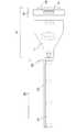
観察光学系として、具体的には、顕微鏡、硬性内視鏡(硬性鏡)等を挙げることができる。当該ズームレンズは、これらの観察光学系の接眼部に接続して好適に使用することができる。以下では、内視鏡、特に硬性鏡の接眼部に接続されて使用される場合を例に挙げて説明する。 Specific examples of the observation optical system include a microscope and a rigid endoscope (rigid endoscope). The zoom lens can be suitably used by being connected to the eyepiece of these observation optical systems. In the following, a case where the endoscope is used by being connected to the eyepiece of a rigid mirror will be described as an example.
硬性鏡は、一般に、狭小部に挿入される細い筒状の挿入部と、当該挿入部に連結された接眼部とを備え、挿入部内には上記対物レンズ系が収容され、接眼部には上述のとおり接眼レンズ系が収容される。医療分野で用いられる硬性鏡の場合、挿入部は患者の体に開けられた穴などを介して体内に挿入され、接眼部は体外に配置される。挿入部の長さを確保するため、挿入部には対物レンズ系と共に上記リレーレンズ系が収容されることもあるし、挿入部と接眼部との間にリレーレンズ系を収容したリレー部が接続されることもある。当該ズームレンズや撮像素子等を備えた撮像装置を硬性鏡の接眼部に接続することで、硬性鏡により取得した被写体像をモニターなどの表示装置に表示させる硬性鏡画像表示システムを実現することができる。 A rigid mirror generally includes a thin tubular insertion portion to be inserted into a narrow portion and an eyepiece portion connected to the insertion portion, and the objective lens system is housed in the insertion portion, and the eyepiece portion has an eyepiece. The eyepiece system is housed as described above. In the case of a rigid scope used in the medical field, the insertion portion is inserted into the body through a hole made in the patient's body, and the eyepiece portion is arranged outside the body. In order to secure the length of the insertion portion, the relay lens system may be accommodated together with the objective lens system in the insertion portion, and a relay portion accommodating the relay lens system is accommodated between the insertion portion and the eyepiece portion. It may be connected. By connecting an imaging device equipped with the zoom lens, an image sensor, etc. to the eyepiece of a rigid mirror, a rigid mirror image display system for displaying a subject image acquired by the rigid mirror on a display device such as a monitor is realized. Can be done.
但し、当該ズームレンズは硬性鏡の接眼部に接続される態様に限定されるものではなく、顕微鏡等、種々の観察光学系の接眼部に接続することができ、これらの観察光学系の接眼部に接続することで、上記と同様な観察画像表示システムを実現することができる。 However, the zoom lens is not limited to the mode in which it is connected to the eyepiece of a rigid mirror, and can be connected to the eyepiece of various observation optical systems such as a microscope. By connecting to the eyepiece, an observation image display system similar to the above can be realized.
上述のように観察光学系の接眼部に接続される態様において当該ズームレンズでは、各可動群の移動量等を調整することにより、撮像視野(観察画角)を連続的に調整して、患部の観察倍率を任意に変化させることができる。そのため、硬性鏡画像表示システムを利用した内視鏡外科手術などの際に、手術の進行に応じて、患部の拡大観察、部分観察等を任意に行うことができる。その際、硬性鏡の挿入部の先端(正確には対物レンズの先端)と患部(被写体)との間の距離、すなわち、硬性鏡の作動距離を変化させる必要がない。従って、手術器具等と干渉しない位置に硬性鏡の挿入部の先端を配置しつつ、手術の進行に応じて要求される観察視野及び観察倍率に調整することができる。さらに、硬性鏡側に変倍機構を設ける必要がないため、硬性鏡の光学構成を簡素にすることができ、硬性鏡の大型化、特に挿入部の大型化を抑制することができる。なお、ここでいう変倍機構とは、被写体像の変倍率を変化させるために設けられる可動群や、可動群を光軸方向に移動させるためのカム等の駆動機構などを指す。 In the embodiment connected to the eyepiece of the observation optical system as described above, in the zoom lens, the imaging field of view (observation angle of view) is continuously adjusted by adjusting the movement amount of each movable group and the like. The observation magnification of the affected area can be changed arbitrarily. Therefore, in the case of endoscopic surgery using a rigid arthroscopic image display system, it is possible to arbitrarily perform magnified observation, partial observation, and the like of the affected area according to the progress of the operation. At that time, it is not necessary to change the distance between the tip of the insertion portion of the rigid mirror (to be exact, the tip of the objective lens) and the affected portion (subject), that is, the operating distance of the rigid mirror. Therefore, it is possible to adjust the observation field of view and the observation magnification required according to the progress of the operation while arranging the tip of the insertion portion of the rigid scope at a position that does not interfere with the surgical instrument or the like. Further, since it is not necessary to provide the scaling mechanism on the rigid mirror side, the optical configuration of the rigid mirror can be simplified, and the enlargement of the rigid mirror, particularly the enlargement of the insertion portion can be suppressed. The scaling mechanism referred to here refers to a movable group provided for changing the scaling of the subject image, a driving mechanism such as a cam for moving the movable group in the optical axis direction, and the like.
このような硬性鏡画像表示システムは、ズームレンズにより生成された光学像に関する画像データを電気的に加工する画像処理部を有することが好ましい。当該画像処理部は、上記撮像装置本体に設けられてもよいし、表示装置の画像表示動作を制御する制御装置(例えば、パーソナルコンピュータ等)に設けられてもよい。 Such a rigid mirror image display system preferably has an image processing unit that electrically processes image data related to an optical image generated by a zoom lens. The image processing unit may be provided in the main body of the image pickup device, or may be provided in a control device (for example, a personal computer or the like) that controls the image display operation of the display device.
上記本件発明に係るズームレンズにおいて、高い変倍比を実現しつつ、小型で高解像度の光学系を得ようとした場合、像形状の歪みが生じやすくなる。そこで、当該観察画像表示システムにおいて、上記画像データに対して像形状の歪みを電気的に加工する画像処理部を設けることにより、像形状の歪みの少ない観察被写体画像を画像出力装置等に出力させることができる。なお、画像処理部は、像形状の歪みを補正するための補正用データを予め記憶した記憶部と、観察撮像装置において取得された画像データと、補正用データとを関連づけて、画像データを補正する演算処理部(CPU)等を備えていることが好ましい。 In the zoom lens according to the present invention, when an attempt is made to obtain a compact and high-resolution optical system while achieving a high magnification ratio, distortion of the image shape is likely to occur. Therefore, in the observation image display system, by providing an image processing unit that electrically processes the distortion of the image shape with respect to the image data, the observation subject image with less distortion of the image shape is output to an image output device or the like. be able to. The image processing unit corrects the image data by associating the storage unit that stores the correction data for correcting the distortion of the image shape in advance, the image data acquired by the observation imaging device, and the correction data. It is preferable to have an arithmetic processing unit (CPU) or the like.
ここで、上記画像処理部は、ズームレンズにより形成された光学像に関する画像データのうち、歪曲収差に関するデータを電気的に加工することが好ましい。画像処理部において、歪曲収差に関するデータを電気的に加工することができれば、上記ズームレンズの第2レンズ群を小さな径のレンズにより構成しつつ、強い屈折力を配置しても、観察被写体像を歪みなく画像出力装置等に表示させることができる。 Here, it is preferable that the image processing unit electrically processes the data related to distortion among the image data related to the optical image formed by the zoom lens. If the image processing unit can electrically process the data related to distortion, the observed subject image can be displayed even if a strong refractive power is arranged while the second lens group of the zoom lens is composed of a lens having a small diameter. It can be displayed on an image output device or the like without distortion.
また、上記画像処理部は、ズームレンズにより形成された光学像に関する画像データのうち、倍率色収差に関するデータを電気的に加工することが好ましい。画像処理部において、倍率色収差に関するデータを電気的に加工することができれば、色収差の小さい被写体像を画像出力装置等に表示させることができる。そのため、ズームレンズを構成するレンズ枚数を削減することが可能になり、当該ズームレンズの小型化を図ることが容易になる。 Further, it is preferable that the image processing unit electrically processes the data related to chromatic aberration of magnification among the image data related to the optical image formed by the zoom lens. If the image processing unit can electrically process data related to chromatic aberration of magnification, a subject image having small chromatic aberration can be displayed on an image output device or the like. Therefore, it is possible to reduce the number of lenses constituting the zoom lens, and it becomes easy to reduce the size of the zoom lens.
次に、実施例を示して本件発明を具体的に説明する。但し、本件発明は以下の実施例に限定されるものではない。以下に挙げる各実施例の光学系は、デジタルカメラ、ビデオカメラ等の撮像装置(光学装置)に用いられる撮像光学系としての観察光学系であり、特に、顕微鏡や、狭小空間の内部観察を行うための観察撮像装置に好ましく適用することができる。また、各レンズ断面図において、図面に向かって左方が観察被写体側(物体側)、右方が像側である。 Next, the present invention will be specifically described with reference to Examples. However, the present invention is not limited to the following examples. The optical systems of each of the following examples are observation optical systems as imaging optical systems used in imaging devices (optical devices) such as digital cameras and video cameras, and in particular, perform internal observation of a microscope or a narrow space. It can be preferably applied to an observation imaging device for this purpose. Further, in each lens cross-sectional view, the left side is the observation subject side (object side) and the right side is the image side when facing the drawing.
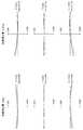
本発明によるズームレンズの実施例を図面を参照して説明する。図1は、本実施例1のズームレンズのレンズ構成例を示す図である。上段が広角端状態におけるレンズ構成図であり、下段が望遠端状態におけるレンズ構成図である。 An embodiment of the zoom lens according to the present invention will be described with reference to the drawings. FIG. 1 is a diagram showing a lens configuration example of the zoom lens of the first embodiment. The upper row is a lens configuration diagram in the wide-angle end state, and the lower row is a lens configuration diagram in the telephoto end state.
図1に示すように、本実施例1のズームレンズは、物体側から順に、正の屈折力を有する第1レンズ群G1と、負の屈折力を有する第2レンズ群G2と、正の屈折力を有する第3レンズ群G3と、負の屈折力を有する第4レンズ群G4から構成されている。当該ズームレンズは、図示しない硬性鏡の接眼部に接続されて使用される。なお、各レンズ群の具体的なレンズ構成は図1に示すとおりである。また、図1において、第1レンズ群G1の物体側に示す「S」は、硬性鏡の接眼部が接続された場合の仮想的な絞り位置を示す。また、「CG」は、カバーガラス、ローパスフィルター、赤外線フィルターなどをさす。「I」は像面であり、CCDセンサやCMOSセンサ等の固体撮像素子の撮像面、或いは、銀塩フィルムのフィルム面等を示す。これらの点は、他の実施例で示す各レンズ断面図においても同様であるため、以下では説明を省略する。 As shown in FIG. 1, the zoom lens of the first embodiment has a first lens group G1 having a positive refractive power, a second lens group G2 having a negative refractive power, and a positive refractive power in this order from the object side. It is composed of a third lens group G3 having a force and a fourth lens group G4 having a negative refractive power. The zoom lens is used by being connected to an eyepiece of a rigid mirror (not shown). The specific lens configuration of each lens group is as shown in FIG. Further, in FIG. 1, “S” shown on the object side of the first lens group G1 indicates a virtual aperture position when the eyepiece portion of the rigid mirror is connected. In addition, "CG" refers to a cover glass, a low-pass filter, an infrared filter, and the like. “I” is an image plane, and indicates an image pickup surface of a solid-state image sensor such as a CCD sensor or a CMOS sensor, a film surface of a silver salt film, or the like. Since these points are the same in the cross-sectional views of each lens shown in other examples, the description thereof will be omitted below.
広角端から望遠端にかけて変倍する際に、第1レンズ群G1と第4レンズ群G4とを光軸方向に固定し、第2レンズ群G2及び第3レンズ群G3はそれぞれ異なる軌跡で像側に移動する。また、無限遠物体から近距離物体への合焦の際には、第2レンズ群G2が像側に移動する。また、第4レンズ群G4は光軸に対して垂直方向に移動可能に構成されており、当該第4レンズ群G4を光軸に対して垂直方向に移動させることにより、手振れなど撮像時に生じた像ブレを補正することができる。 When scaling from the wide-angle end to the telephoto end, the first lens group G1 and the fourth lens group G4 are fixed in the optical axis direction, and the second lens group G2 and the third lens group G3 have different trajectories on the image side. Move to. Further, when focusing from an infinite object to a short-distance object, the second lens group G2 moves to the image side. Further, the fourth lens group G4 is configured to be movable in the direction perpendicular to the optical axis, and by moving the fourth lens group G4 in the direction perpendicular to the optical axis, camera shake or the like occurs during imaging. Image blur can be corrected.
なお、本実施例1のズームレンズにおいて、第3レンズ群は第n−1レンズ群であり、第4レンズ群は第nレンズ群である。 In the zoom lens of the first embodiment, the third lens group is the n-1 lens group, and the fourth lens group is the nth lens group.
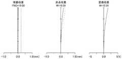
図2〜図4に、本実施例1のズームレンズの広角端状態、中間焦点距離状態及び望遠端状態における無限遠合焦時の球面収差、非点収差及び歪曲収差の縦収差図をそれぞれ示す。球面収差図において、縦軸はFナンバー(図中、FNOで示す)を表し、実線はd線(波長λ=587.56nm)、短破線はg線(波長λ=435.84nm)、長破線はC線(波長λ=656.27nm)の特性である。非点収差図において、縦軸は画角(図中、Wで示す)を表し、実線はサジタル平面(図中、Sで示す)、破線はメリディオナル平面(図中、Mで示す)の特性である。歪曲収差図において、縦軸は画角(図中、Wで示す)を表す。但し、これらは、当該ズームレンズ自体の特性であり、当該ズームレンズを硬性鏡の接眼部に接続せずに単独で用いたときの特性である。次に説明する横収差についても同様である。なお、各横収差図のdecは防振群の移動量を表す。 2 to 4 show longitudinal aberration diagrams of spherical aberration, astigmatism, and distortion at infinity in the wide-angle end state, intermediate focal length state, and telephoto end state of the zoom lens of the first embodiment, respectively. .. In the spherical aberration diagram, the vertical axis represents the F number (indicated by FNO in the figure), the solid line is the d line (wavelength λ = 587.56 nm), the short broken line is the g line (wavelength λ = 435.84 nm), and the long broken line is C. This is a characteristic of the line (wavelength λ = 656.27 nm). In the astigmatism diagram, the vertical axis represents the angle of view (indicated by W in the figure), the solid line represents the characteristics of the sagittal plane (indicated by S in the figure), and the broken line represents the characteristics of the meridional plane (indicated by M in the figure). is there. In the distortion diagram, the vertical axis represents the angle of view (indicated by W in the figure). However, these are the characteristics of the zoom lens itself, and are the characteristics when the zoom lens is used alone without being connected to the eyepiece of the rigid mirror. The same applies to the lateral aberration described below. The dec in each lateral aberration diagram represents the amount of movement of the vibration isolation group.
また、図5は、実施例1のズームレンズの望遠端における横収差図である。図5に示す各横収差図において、図面に向かって左側に位置する3つの収差図は、望遠端における手振れ補正を行っていない基本状態に対応する(防振補正量0deg)。また、図面に向かって右側に位置する3つの収差図は、防振群としての第4レンズ群を光軸と垂直な方向に所定量移動させた望遠端における手振れ補正状態に対応する。 Further, FIG. 5 is a lateral aberration diagram at the telephoto end of the zoom lens of the first embodiment. In each lateral aberration diagram shown in FIG. 5, the three aberration diagrams located on the left side of the drawing correspond to the basic state in which the camera shake correction is not performed at the telephoto end (vibration
基本状態の各横収差図のうち、上段は最大像高の70%の像点における横収差、中段は軸上像点における横収差、下段は最大像高の−70%の像点における横収差に、それぞれ対応する。手振れ補正状態の各横収差図のうち、上段は最大像高の70%の像点における横収差、中段は軸上像点における横収差、下段は最大像高の−70%の像点における横収差に、それぞれ対応する。また各横収差図において、横軸は瞳面上での主光線からの距離を表し、実線はd線、短破線はg線、長破線はC線の特性である。また、当該ズームレンズについて、手振れ補正時に防振群を光軸に対して垂直な方向に所定量移動させることによる角度変化量は0.3度である。また、そのときの防振群の移動量は0.836mmである。 Of each lateral aberration diagram in the basic state, the upper row is the lateral aberration at the image point of 70% of the maximum image height, the middle row is the lateral aberration at the axial image point, and the lower row is the lateral aberration at the image point of -70% of the maximum image height. Corresponds to each. Of each lateral aberration diagram in the image stabilization state, the upper row is the lateral aberration at the image point of 70% of the maximum image height, the middle row is the lateral aberration at the axial image point, and the lower row is the lateral aberration at the image point of -70% of the maximum image height. Corresponds to each aberration. Further, in each lateral aberration diagram, the horizontal axis represents the distance from the main ray on the pupil plane, the solid line is the d-line, the short dashed line is the g-line, and the long dashed line is the C-line. Further, with respect to the zoom lens, the amount of change in angle due to the movement of the vibration isolation group in a direction perpendicular to the optical axis by a predetermined amount during camera shake correction is 0.3 degrees. The amount of movement of the vibration isolation group at that time is 0.836 mm.
図5から明らかなように、軸上像点における横収差の対称性は良好であることがわかる。また、+70%像点における横収差と−70%像点における横収差とを基本状態で比較すると、いずれも湾曲度が小さく、収差曲線の傾斜がほぼ等しいことから、偏心コマ収差、偏心非点収差が小さいことがわかる。このことは、手振れ補正状態であっても充分な結像性能が得られていることを意味している。また、いずれのズーム位置であっても、0.3°までの手振れ補正角に対して、結像特性を低下させることなく充分な手振れ補正を行うことが可能である。さらに、光軸に対して垂直な方向における防振群の移動量を更に大きくとることで、手振れ補正角度を0.3°よりも更に大きく取ることも可能である。これらの点は、後述する他の実施例についても同様である。 As is clear from FIG. 5, it can be seen that the symmetry of the lateral aberration at the axial image point is good. Further, when the lateral aberration at the + 70% image point and the lateral aberration at the -70% image point are compared in the basic state, the degree of curvature is small and the inclinations of the aberration curves are almost the same. Therefore, eccentric coma aberration and eccentric astigmatism It can be seen that the aberration is small. This means that sufficient imaging performance is obtained even in the image stabilization state. Further, at any zoom position, it is possible to perform sufficient image stabilization for an image stabilization angle up to 0.3 ° without deteriorating the imaging characteristics. Further, by further increasing the amount of movement of the vibration isolation group in the direction perpendicular to the optical axis, it is possible to take the camera shake correction angle even larger than 0.3 °. These points are the same for other examples described later.
次に、当該本実施例1において、具体的数値を適用した数値実施例1のレンズデータを表1に示す。表1に示すレンズデータは次のものである。「面番号」は、物体側から数えたレンズ面の順番を示す。「r」はレンズ面の曲率半径を示し、「d」はレンズ厚又は、互いに隣接するレンズ面の光軸上の間隔を示し、「nd」はd線に対する屈折率を示し、「vd」はd線に対するアッベ数を示す。また、「r」の欄に記載の「∞」は曲率半径が∞(無限大)であることを意味する。また、「d」の欄に記載の「d5」等の「dn(但し、nは面番号)」と表記された欄は、変倍時における可変間隔であることを示す。なお、各表中の長さの単位は全て「mm」であり、画角の単位は全て「°」である。 Next, Table 1 shows the lens data of Numerical Example 1 to which specific numerical values are applied in the present Example 1. The lens data shown in Table 1 are as follows. The "plane number" indicates the order of the lens planes counted from the object side. “R” indicates the radius of curvature of the lens surface, “d” indicates the lens thickness or the distance between the lens surfaces adjacent to each other on the optical axis, “nd” indicates the refractive index with respect to the d line, and “vd” indicates the refractive index with respect to the d line. The Abbe number for the d line is shown. Further, "∞" described in the column of "r" means that the radius of curvature is ∞ (infinity). Further, the column described as "dn (where n is a surface number)" such as "d5" described in the column of "d" indicates that the interval is variable at the time of scaling. The unit of length in each table is "mm", and the unit of angle of view is "°".
表2に、当該ズームレンズの各種データを示す。表2には、広角端、中間焦点距離位置、望遠端における当該ズームレンズの「焦点距離」、「Fナンバー」、「半画角」、「レンズ全長(光学全長)」、「バックフォーカス」、表1に示した変倍時における光軸上の可変間隔(但し、無限遠合焦時)「dn」を示す。また、表2に、当該ズームレンズの変倍比、像高を併せて示す。 Table 2 shows various data of the zoom lens. Table 2 shows the "focal length", "F number", "half angle of view", "total lens length (optical total length)", "back focus" of the zoom lens at the wide-angle end, intermediate focal length position, and telephoto end. Table 1 shows the variable interval (however, at infinity in focus) “dn” on the optical axis at the time of scaling. Table 2 also shows the magnification ratio and image height of the zoom lens.
表3に、当該ズームレンズを構成する各レンズ群の「始面」、「焦点距離」、各レンズ群の始面から終面までの光軸上の長さに相当する「構成長」、変倍時における各レンズ群の光軸上の「移動量」を示す。但し、像側への移動に対して、符号を正とする。 Table 3 shows the "starting surface" and "focal length" of each lens group constituting the zoom lens, and the "constituent length" corresponding to the length on the optical axis from the starting surface to the ending surface of each lens group. The "movement amount" on the optical axis of each lens group at the time of magnification is shown. However, the sign is positive for the movement to the image side.
表4に、広角端、中間焦点距離位置、望遠端における各レンズ群の横倍率を各レンズ群の始面と共に示す。 Table 4 shows the lateral magnification of each lens group at the wide-angle end, the intermediate focal length position, and the telephoto end together with the start surface of each lens group.
表5に、当該ズームレンズの望遠端における最大撮像倍率と、望遠端における最近点物体合焦時の光軸上の可変間隔を示す。なお、最近点物体は、当該ズームレンズの最短撮像距離位置にある物体を意味する。 Table 5 shows the maximum imaging magnification at the telephoto end of the zoom lens and the variable interval on the optical axis when the nearest point object is in focus at the telephoto end. The recent point object means an object at the shortest imaging distance position of the zoom lens.
そして、表26に当該ズームレンズの上記条件式(1)〜条件式(6)の数値を示す。 Then, Table 26 shows the numerical values of the above conditional expressions (1) to (6) of the zoom lens.
これらの図面及び表に関する事項は、他の実施例においても同様であるため、以下では説明を省略する。 Since the matters relating to these drawings and tables are the same in the other embodiments, the description thereof will be omitted below.

(1)光学系の構成
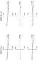
図6は、本件発明に係る実施例2のズームレンズのレンズ構成例を示す断面図である。図6に示すように、本実施例2のズームレンズは、物体側から順に、正の屈折力を有する第1レンズ群G1と、負の屈折力を有する第2レンズ群G2と、正の屈折力を有する第3レンズ群G3と、負の屈折力を有する第4レンズ群G4から構成されている。当該ズームレンズは、図示しない硬性鏡の接眼部に接続されて使用される。なお、各レンズ群の具体的なレンズ構成は図6に示すとおりである。なお、第3レンズ群G3は第n−1レンズ群であり、第4レンズ群G4は第nレンズ群である。(1) Configuration of Optical System FIG. 6 is a cross-sectional view showing a lens configuration example of the zoom lens of the second embodiment according to the present invention. As shown in FIG. 6, the zoom lens of the second embodiment has a first lens group G1 having a positive refractive power, a second lens group G2 having a negative refractive power, and a positive refractive power in this order from the object side. It is composed of a third lens group G3 having a force and a fourth lens group G4 having a negative refractive power. The zoom lens is used by being connected to an eyepiece of a rigid mirror (not shown). The specific lens configuration of each lens group is as shown in FIG. The third lens group G3 is the n-1th lens group, and the fourth lens group G4 is the nth lens group.
広角端から望遠端にかけて変倍する際に、第1レンズ群G1と第4レンズ群G4とを光軸方向に固定し、第2レンズ群G2及び第3レンズ群G3はそれぞれ異なる軌跡で像側に移動する。また、無限遠物体から近距離物体への合焦の際には、第2レンズ群G2が像側に移動する。また、第4レンズ群G4は光軸に対して垂直方向に移動可能に構成されており、当該第4レンズ群G4を光軸に対して垂直方向に移動させることにより、手振れなど撮像時に生じた像ブレを補正することができる。また、手振れ補正時に防振群を光軸に対して垂直な方向に所定量移動させることによる角度変化量を0.3度としたときの防振群の移動量は0.779mmである。 When scaling from the wide-angle end to the telephoto end, the first lens group G1 and the fourth lens group G4 are fixed in the optical axis direction, and the second lens group G2 and the third lens group G3 have different trajectories on the image side. Move to. Further, when focusing from an infinite object to a short-distance object, the second lens group G2 moves to the image side. Further, the fourth lens group G4 is configured to be movable in the direction perpendicular to the optical axis, and by moving the fourth lens group G4 in the direction perpendicular to the optical axis, camera shake or the like occurs during imaging. Image blur can be corrected. Further, the amount of movement of the anti-vibration group is 0.779 mm when the amount of change in angle due to the movement of the anti-vibration group in a direction perpendicular to the optical axis by a predetermined amount during image stabilization is 0.3 degrees.
(2)数値実施例
次に、当該ズームレンズの具体的数値を適用した数値実施例について説明する。表6に当該ズームレンズの面データを示し、表7に各種データを示し、表8に当該ズームレンズを構成する各レンズ群に関するデータを示し、表9に各レンズ群の横倍率等を示し、表10に当該ズームレンズの望遠端における最大撮像倍率等を示す。そして、表26に当該ズームレンズの上記条件式(1)〜条件式(6)の数値を示す。(2) Numerical Example Next, a numerical example to which a specific numerical value of the zoom lens is applied will be described. Table 6 shows the surface data of the zoom lens, Table 7 shows various data, Table 8 shows the data related to each lens group constituting the zoom lens, and Table 9 shows the lateral magnification of each lens group. Table 10 shows the maximum imaging magnification and the like at the telephoto end of the zoom lens. Then, Table 26 shows the numerical values of the above conditional expressions (1) to (6) of the zoom lens.
図7〜図9に、本実施例2のズームレンズの広角端状態、中間焦点距離状態及び望遠端状態における無限遠合焦時の球面収差、非点収差及び歪曲収差をそれぞれ示す。図10に、実施例2のズームレンズの望遠端における横収差図を示す。 7 to 9 show spherical aberration, astigmatism, and distortion at infinity in the wide-angle end state, intermediate focal length state, and telephoto end state of the zoom lens of the second embodiment, respectively. FIG. 10 shows a lateral aberration diagram at the telephoto end of the zoom lens of Example 2.
(1)光学系の構成
図11は、本件発明に係る実施例3のズームレンズのレンズ構成例を示す断面図である。図11に示すように、本実施例3のズームレンズは、物体側から順に、正の屈折力を有する第1レンズ群G1と、負の屈折力を有する第2レンズ群G2と、正の屈折力を有する第3レンズ群G3と、負の屈折力を有する第4レンズ群G4から構成されている。当該ズームレンズは、図示しない硬性鏡の接眼部に接続されて使用される。なお、各レンズ群の具体的なレンズ構成は図11に示すとおりである。なお、第3レンズ群G3は第n−1レンズ群であり、第4レンズ群G4は第nレンズ群である。(1) Configuration of Optical System FIG. 11 is a cross-sectional view showing a lens configuration example of the zoom lens of the third embodiment according to the present invention. As shown in FIG. 11, in the zoom lens of the third embodiment, the first lens group G1 having a positive refractive power, the second lens group G2 having a negative refractive power, and the positive refractive power are sequentially arranged from the object side. It is composed of a third lens group G3 having a force and a fourth lens group G4 having a negative refractive power. The zoom lens is used by being connected to an eyepiece of a rigid mirror (not shown). The specific lens configuration of each lens group is as shown in FIG. The third lens group G3 is the n-1th lens group, and the fourth lens group G4 is the nth lens group.
広角端から望遠端にかけて変倍する際に、第1レンズ群G1と第4レンズ群G4とを光軸方向に固定し、第2レンズ群G2及び第3レンズ群G3はそれぞれ異なる軌跡で像側に移動する。また、無限遠物体から近距離物体への合焦の際には、第2レンズ群G2が像側に移動する。また、第4レンズ群G4は光軸に対して垂直方向に移動可能に構成されており、当該第4レンズ群G4を光軸に対して垂直方向に移動させることにより、手振れなど撮像時に生じた像ブレを補正することができる。また、手振れ補正時に防振群を光軸に対して垂直な方向に所定量移動させることによる角度変化量を0.3度としたときの防振群の移動量は0.640mmである。 When scaling from the wide-angle end to the telephoto end, the first lens group G1 and the fourth lens group G4 are fixed in the optical axis direction, and the second lens group G2 and the third lens group G3 have different trajectories on the image side. Move to. Further, when focusing from an infinite object to a short-distance object, the second lens group G2 moves to the image side. Further, the fourth lens group G4 is configured to be movable in the direction perpendicular to the optical axis, and by moving the fourth lens group G4 in the direction perpendicular to the optical axis, camera shake or the like occurs during imaging. Image blur can be corrected. Further, the amount of movement of the anti-vibration group is 0.640 mm when the amount of change in angle due to the movement of the anti-vibration group in a direction perpendicular to the optical axis by a predetermined amount during image stabilization is 0.3 degrees.
(2)数値実施例
次に、当該ズームレンズの具体的数値を適用した数値実施例について説明する。表11に当該ズームレンズの面データを示し、表12に各種データを示し、表13に当該ズームレンズを構成する各レンズ群に関するデータを示し、表14に各レンズ群の横倍率等を示し、表15に当該ズームレンズの望遠端における最大撮像倍率等を示す。そして、表26に当該ズームレンズの上記条件式(1)〜条件式(6)の数値を示す。(2) Numerical Example Next, a numerical example to which a specific numerical value of the zoom lens is applied will be described. Table 11 shows the surface data of the zoom lens, Table 12 shows various data, Table 13 shows the data related to each lens group constituting the zoom lens, and Table 14 shows the lateral magnification of each lens group. Table 15 shows the maximum imaging magnification and the like at the telephoto end of the zoom lens. Then, Table 26 shows the numerical values of the above conditional expressions (1) to (6) of the zoom lens.
図12〜図14に、本実施例3のズームレンズの広角端状態、中間焦点距離状態及び望遠端状態における無限遠合焦時の球面収差、非点収差及び歪曲収差をそれぞれ示す。図15に、実施例3のズームレンズの望遠端における横収差図を示す。 12 to 14 show spherical aberration, astigmatism, and distortion at infinity in the wide-angle end state, intermediate focal length state, and telephoto end state of the zoom lens of the third embodiment, respectively. FIG. 15 shows a lateral aberration diagram at the telephoto end of the zoom lens of Example 3.
(1)光学系の構成
図16は、本件発明に係る実施例4のズームレンズのレンズ構成例を示す断面図である。図16に示すように、本実施例4のズームレンズは、物体側から順に、正の屈折力を有する第1レンズ群G1と、負の屈折力を有する第2レンズ群G2と、正の屈折力を有する第3レンズ群G3と、負の屈折力を有する第4レンズ群G4から構成されている。当該ズームレンズは、図示しない硬性鏡の接眼部に接続されて使用される。なお、各レンズ群の具体的なレンズ構成は図16に示すとおりである。なお、第3レンズ群G3は第n−1レンズ群であり、第4レンズ群G4は第nレンズ群である。(1) Configuration of Optical System FIG. 16 is a cross-sectional view showing a lens configuration example of the zoom lens of the fourth embodiment according to the present invention. As shown in FIG. 16, the zoom lens of the fourth embodiment has a first lens group G1 having a positive refractive power, a second lens group G2 having a negative refractive power, and a positive refractive power in this order from the object side. It is composed of a third lens group G3 having a force and a fourth lens group G4 having a negative refractive power. The zoom lens is used by being connected to an eyepiece of a rigid mirror (not shown). The specific lens configuration of each lens group is as shown in FIG. The third lens group G3 is the n-1th lens group, and the fourth lens group G4 is the nth lens group.
広角端から望遠端にかけて変倍する際に、第1レンズ群G1と第4レンズ群G4とを光軸方向に固定し、第2レンズ群G2及び第3レンズ群G3はそれぞれ異なる軌跡で像側に移動する。また、無限遠物体から近距離物体への合焦の際には、第2レンズ群G2が像側に移動する。また、第4レンズ群G4は光軸に対して垂直方向に移動可能に構成されており、当該第4レンズ群G4を光軸に対して垂直方向に移動させることにより、手振れなど撮像時に生じた像ブレを補正することができる。また、手振れ補正時に防振群を光軸に対して垂直な方向に所定量移動させることによる角度変化量を0.3度としたときの防振群の移動量は1.416mmである。 When scaling from the wide-angle end to the telephoto end, the first lens group G1 and the fourth lens group G4 are fixed in the optical axis direction, and the second lens group G2 and the third lens group G3 have different trajectories on the image side. Move to. Further, when focusing from an infinite object to a short-distance object, the second lens group G2 moves to the image side. Further, the fourth lens group G4 is configured to be movable in the direction perpendicular to the optical axis, and by moving the fourth lens group G4 in the direction perpendicular to the optical axis, camera shake or the like occurs during imaging. Image blur can be corrected. Further, the amount of movement of the anti-vibration group is 1.416 mm when the amount of change in angle due to the movement of the anti-vibration group in a direction perpendicular to the optical axis by a predetermined amount during image stabilization is 0.3 degrees.
(2)数値実施例
次に、当該ズームレンズの具体的数値を適用した数値実施例について説明する。表16に当該ズームレンズの面データを示し、表17に各種データを示し、表18に当該ズームレンズを構成する各レンズ群に関するデータを示し、表19に各レンズ群の横倍率等を示し、表20に当該ズームレンズの望遠端における最大撮像倍率等を示す。そして、表26に当該ズームレンズの上記条件式(1)〜条件式(6)の数値を示す。(2) Numerical Example Next, a numerical example to which a specific numerical value of the zoom lens is applied will be described. Table 16 shows the surface data of the zoom lens, Table 17 shows various data, Table 18 shows the data related to each lens group constituting the zoom lens, and Table 19 shows the lateral magnification of each lens group. Table 20 shows the maximum imaging magnification and the like at the telephoto end of the zoom lens. Then, Table 26 shows the numerical values of the above conditional expressions (1) to (6) of the zoom lens.
図17〜図19に、本実施例4のズームレンズの広角端状態、中間焦点距離状態及び望遠端状態における無限遠合焦時の球面収差、非点収差及び歪曲収差をそれぞれ示す。図20に、実施例4のズームレンズの望遠端における横収差図を示す。 17 to 19 show spherical aberration, astigmatism, and distortion at infinity in the wide-angle end state, intermediate focal length state, and telephoto end state of the zoom lens of the fourth embodiment, respectively. FIG. 20 shows a lateral aberration diagram at the telephoto end of the zoom lens of Example 4.
(1)光学系の構成
図21は、本件発明に係る実施例5のズームレンズのレンズ構成例を示す断面図である。図21に示すように、本実施例5のズームレンズは、物体側から順に、正の屈折力を有する第1レンズ群G1と、負の屈折力を有する第2レンズ群G2と、正の屈折力を有する第3レンズ群G3と、正の屈折力を有する第4レンズ群G4と、負の屈折力を有する第5レンズ群G4とから構成されている。当該ズームレンズは、図示しない硬性鏡の接眼部に接続されて使用される。なお、各レンズ群の具体的なレンズ構成は図16に示すとおりである。
なお、第4レンズ群G4は第n−1レンズ群であり、第5レンズ群G5は第nレンズ群である。(1) Configuration of Optical System FIG. 21 is a cross-sectional view showing a lens configuration example of the zoom lens of the fifth embodiment according to the present invention. As shown in FIG. 21, the zoom lens of the fifth embodiment has a first lens group G1 having a positive refractive power, a second lens group G2 having a negative refractive power, and a positive refractive power in this order from the object side. It is composed of a third lens group G3 having a force, a fourth lens group G4 having a positive refractive power, and a fifth lens group G4 having a negative refractive power. The zoom lens is used by being connected to an eyepiece of a rigid mirror (not shown). The specific lens configuration of each lens group is as shown in FIG.
The fourth lens group G4 is the n-1th lens group, and the fifth lens group G5 is the nth lens group.
広角端から望遠端にかけて変倍する際に、第1レンズ群G1と第4レンズ群G4とを光軸方向に固定し、第2レンズ群G2、第3レンズ群G3及び第4レンズ群G4はそれぞれ異なる軌跡で像側に移動する。また、無限遠物体から近距離物体への合焦の際には、第2レンズ群G2が像側に移動する。また、第5レンズ群G5は光軸に対して垂直方向に移動可能に構成されており、当該第5レンズ群G5を光軸に対して垂直方向に移動させることにより、手振れなど撮像時に生じた像ブレを補正することができる。また、手振れ補正時に防振群を光軸に対して垂直な方向に所定量移動させることによる角度変化量を0.3度としたときの防振群の移動量は0.823mmである。 When scaling from the wide-angle end to the telephoto end, the first lens group G1 and the fourth lens group G4 are fixed in the optical axis direction, and the second lens group G2, the third lens group G3, and the fourth lens group G4 They move to the image side with different trajectories. Further, when focusing from an infinite object to a short-distance object, the second lens group G2 moves to the image side. Further, the fifth lens group G5 is configured to be movable in the direction perpendicular to the optical axis, and by moving the fifth lens group G5 in the direction perpendicular to the optical axis, camera shake or the like occurs during imaging. Image blur can be corrected. Further, the amount of movement of the anti-vibration group is 0.823 mm when the amount of change in angle due to the movement of the anti-vibration group in a direction perpendicular to the optical axis by a predetermined amount during image stabilization is 0.3 degrees.
(2)数値実施例
次に、当該ズームレンズの具体的数値を適用した数値実施例について説明する。表21に当該ズームレンズの面データを示し、表22に各種データを示し、表23に当該ズームレンズを構成する各レンズ群に関するデータを示し、表24に各レンズ群の横倍率等を示し、表25に当該ズームレンズの望遠端における最大撮像倍率等を示す。そして、表26に当該ズームレンズの上記条件式(1)〜条件式(6)の数値を示す。(2) Numerical Example Next, a numerical example to which a specific numerical value of the zoom lens is applied will be described. Table 21 shows the surface data of the zoom lens, Table 22 shows various data, Table 23 shows the data related to each lens group constituting the zoom lens, and Table 24 shows the lateral magnification of each lens group. Table 25 shows the maximum imaging magnification and the like at the telephoto end of the zoom lens. Then, Table 26 shows the numerical values of the above conditional expressions (1) to (6) of the zoom lens.
図21〜図23に、本実施例5のズームレンズの広角端状態、中間焦点距離状態及び望遠端状態における無限遠合焦時の球面収差、非点収差及び歪曲収差をそれぞれ示す。図25に、実施例5のズームレンズの望遠端における横収差図を示す。 21 to 23 show spherical aberration, astigmatism, and distortion at infinity in the wide-angle end state, intermediate focal length state, and telephoto end state of the zoom lens of the fifth embodiment, respectively. FIG. 25 shows a lateral aberration diagram at the telephoto end of the zoom lens of Example 5.
(撮像装置の実施例)
次に、本件発明に係る撮像装置の実施例について説明する。本件発明に係る撮像装置10は、硬性鏡20に接続されて使用される。当該撮像装置10は、本件発明に係るズームレンズ11を収容するレンズユニットと、当該レンズユニットが交換自在に取り付けられる撮像装置本体12とを備えている。レンズユニットには、例えば、上記実施例1〜実施例5のいずれかのズームレンズを収容することができる。各実施例の第1レンズ群G1において最も物体側に配置される平板(面番号1、2)はカバーガラスであり、当該カバーガラスによりレンズユニット筐体(鏡筒)内に物体側(接眼部側)から塵や埃、水などが侵入するのを防止する。また、当該ズームレンズにおいて最も像側に配置されるレンズと、レンズユニットの筐体とは密閉されており、レンズユニット筐体内に像側からの塵や埃、水などの侵入も防止されている。撮像装置本体12内には、撮像素子13(I)が配置され、撮像素子13の物体側にはカバーガラス(CG)が配置される。撮像装置本体の背面側には液晶モニターなどの表示装置14が設けられている。(Example of imaging device)
Next, an example of the image pickup apparatus according to the present invention will be described. The
硬性鏡20は、物体側から順に、対物レンズ系(図示略)、リレーレンズ系(図示略)、接眼レンズ系(図示略)が収容される鏡筒部21と、光源22と、照明光学系23とを備えている。鏡筒部21は、光学全長方向に長尺に形成されており、その物体側が上述した挿入部に相当し、例えば、患者の体内等に挿入される。鏡筒部21の像側は上述した接眼部に相当し、当該接眼部を介して医師等は、患者の体内、すなわち患部等を観察することができる。また、当該接眼部にレンズユニットが接続される。光源22は、鏡筒部21の外側であって接眼部の近傍に設けられる。照明光学系23は、光源22からの照明光を鏡筒部21の物体側まで伝達し、患部等を照明する。図26には記載を省略したが、撮像装置本体11と、上述した画像処理部を備えるパーソナルコンピュータ等とを通信接続手段を介して接続し、パーソナルコンピュータ等の表示装置に硬性鏡20及び撮像装置10により取得した患部等の硬性鏡画像(観察画像)を表示させてもよい。また、当該撮像装置本体又は、撮像装置本体と接続されたパーソナルコンピュータ等と、遠隔地にあるパーソナルコンピュータ等とをインターネット等の通信接続手段を介して接続し、遠隔地にある表示装置に患部等の硬性鏡画像を表示させてもよい。このような構成により、上記硬性鏡画像表示システム(観察画像表示システム)を実現することができる。 The
なお、当該撮像装置の実施例では、撮像装置10と硬性鏡20とは接続自在に接続されている。また、当該撮像装置の実施例では、変倍光学系11を収容するレンズユニットは、撮像装置本体12に対して交換自在に取り付けられている。しかしながら、本件発明に係る撮像装置はこれらの態様に限定されるものではなく、レンズユニットと撮像装置本体12とが一体に(分離不能に)構成されていてもよいし、撮像装置10と硬性鏡20とが一体に構成されていてもよいのは勿論である。 In the embodiment of the imaging device, the
本件発明によれば、全体として小型化及び軽量化を図りつつ、近接撮像が可能なズームレンズを提供することができる。 According to the present invention, it is possible to provide a zoom lens capable of close-up imaging while achieving miniaturization and weight reduction as a whole.
G1・・・第1レンズ群
G2・・・第2レンズ群
G3・・・第3レンズ群
G4・・・第4レンズ群
G5・・・第5レンズ群
F・・・合焦群
VC・・・防振群
S・・・仮想絞り位置
10・・・撮像装置
11・・・ズームレンズ
12・・・撮像装置本体
13・・・撮像素子
14・・・表示装置
20・・・硬性鏡(観察光学系)
21・・・鏡筒部
22・・・光源
23・・・照明光学系G1 ... 1st lens group G2 ... 2nd lens group G3 ... 3rd lens group G4 ... 4th lens group G5 ... 5th lens group F ... Focusing group VC ...・ Vibration isolation group S ・ ・ ・
21 ...
Claims (8)
Translated fromJapanese物体側から順に、正の屈折力を有する第1レンズ群と、負の屈折力を有する第2レンズ群とを備え、
像側から順に、負の屈折力を有する第nレンズ群と、正の屈折力を有する第n−1レンズ群とを備え、各レンズ群間の空気間隔を変化させることで変倍を行うズームレンズであって、
広角端から望遠端にかけて変倍する際に、前記第1レンズ群と前記第nレンズ群とを光軸方向に固定し、前記第1レンズ群と前記第2レンズ群との間隔を広く、前記第n−1レンズ群と前記第nレンズ群との間隔が狭くなるように、前記第2レンズ群と前記第n−1レンズ群とを光軸方向に移動させ、
無限遠物体から近距離物体への合焦の際に、前記第1レンズ群及び前記第nレンズ群以外の1つのレンズ群を光軸方向に移動することによって合焦し、
以下の条件を満足することを特徴とするズームレンズ。
(1) 0.40 ≦ m2/mn−1 ≦ 3.00
(4) bt ≦ −0.80
但し、
m2 :広角端から望遠端への変倍時における前記第2レンズ群の移動量(像側への移動に対して、符号を正とする)
mn−1:広角端から望遠端への変倍時における前記第n−1レンズ群の移動量(像側への移動に対して、符号を正とする)
bt:当該ズームレンズ全系の望遠端における最大撮像倍率It consists of n lens groups (where n is a natural number of 4 or more).
A first lens group having a positive refractive power and a second lens group having a negative refractive power are provided in this order from the object side.
A zoom that includes an nth lens group with a negative refractive power and an n-1 lens group with a positive refractive power in order from the image side, and changes the magnification by changing the air spacing between the lens groups. It ’s a lens
When scaling from the wide-angle end to the telescopic end, the first lens group and the n-th lens group are fixed in the optical axis direction, and the distance between the first lens group and the second lens group is widened. The second lens group and the n-1 lens group are moved in the optical axis direction so that the distance between the n-1 lens group and the nth lens group is narrowed.
When focusing from an infinity object to a short-range object, the lens group other than the first lens group and the nth lens group is moved in the optical axis direction to focus.
A zoom lens characterized by satisfying the following conditions.
(1) 0.40 ≤ m2 / mn-1 ≤ 3.00
(4) bt ≤ −0.80
However,
m2: Amount of movement of the second lens group at the time of scaling from the wide-angle end to the telephoto end (the sign is positive with respect to the movement toward the image side).
mn-1: Amount of movement of the n-1 lens group at the time of scaling from the wide-angle end to the telephoto end (the sign is positive with respect to the movement toward the image side).
bt: Maximum imaging magnification at the telephoto end of the entire zoom lens system
物体側から順に、正の屈折力を有する第1レンズ群と、負の屈折力を有する第2レンズ群とを備え、A first lens group having a positive refractive power and a second lens group having a negative refractive power are provided in this order from the object side.
像側から順に、負の屈折力を有する第nレンズ群と、正の屈折力を有する第n−1レンズ群とを備え、各レンズ群間の空気間隔を変化させることで変倍を行うズームレンズであって、A zoom that includes an nth lens group with a negative refractive power and an n-1 lens group with a positive refractive power in order from the image side, and changes the magnification by changing the air spacing between the lens groups. It ’s a lens
広角端から望遠端にかけて変倍する際に、前記第1レンズ群と前記第nレンズ群とを光軸方向に固定し、前記第1レンズ群と前記第2レンズ群との間隔を広く、前記第n−1レンズ群と前記第nレンズ群との間隔が狭くなるように、前記第2レンズ群と前記第n−1レンズ群とを光軸方向に移動させ、When scaling from the wide-angle end to the telescopic end, the first lens group and the n-th lens group are fixed in the optical axis direction, and the distance between the first lens group and the second lens group is widened. The second lens group and the n-1 lens group are moved in the optical axis direction so that the distance between the n-1 lens group and the nth lens group is narrowed.
無限遠物体から近距離物体への合焦の際に、前記第1レンズ群及び前記第nレンズ群以外の1つのレンズ群を光軸方向に移動することによって合焦し、When focusing from an infinity object to a short-range object, the lens group other than the first lens group and the nth lens group is moved in the optical axis direction to focus.
以下の条件を満足することを特徴とするズームレンズ。A zoom lens characterized by satisfying the following conditions.
(1) 0.40 ≦ m2/mn−1 ≦ 3.00(1) 0.40 ≤ m2 / mn-1 ≤ 3.00
(2−1) 1.30 ≦ bnt ≦ 3.00(2-1) 1.30 ≤ bnt ≤ 3.00
但し、However,
m2 :広角端から望遠端への変倍時における前記第2レンズ群の移動量(像側への移動に対して、符号を正とする)m2: Amount of movement of the second lens group at the time of scaling from the wide-angle end to the telephoto end (the sign is positive with respect to the movement toward the image side).
mn−1:広角端から望遠端への変倍時における前記第n−1レンズ群の移動量(像側への移動に対して、符号を正とする)mn-1: Amount of movement of the n-1 lens group at the time of scaling from the wide-angle end to the telephoto end (the sign is positive with respect to the movement toward the image side).
bnt: 望遠端における無限遠物体合焦時の前記第nレンズ群の横倍率bnt: Lateral magnification of the nth lens group when focusing on an infinity object at the telephoto end
(2) 1.00 ≦ bnt ≦ 3.00
但し、
bnt: 望遠端における無限遠物体合焦時の前記第nレンズ群の横倍率The zoom lens according to claim 1, which satisfies the following conditions.
(2) 1.00 ≤ bnt ≤ 3.00
However,
bnt: Lateral magnification of the nth lens group when focusing on an infinity object at the telephoto end
(3) 0.30 ≦ |f2|/√(fw×ft) ≦ 1.00
但し、
f2:前記第2レンズ群の焦点距離
fw:広角端における無限遠物体合焦時の当該ズームレンズ全系の焦点距離
ft:望遠端における無限遠物体合焦時の当該ズームレンズ全系の焦点距離The zoom lens according toany one of claims 1 to 3, which satisfies the following conditions.
(3) 0.30 ≤ | f2 | / √ (fw x ft) ≤ 1.00
However,
f2: Focal length of the second lens group fw: Focal length of the entire zoom lens system when the infinity object is in focus at the wide-angle end ft: Focal length of the entire zoom lens system when the infinity object is in focus at the telephoto end
(5) 0.10 ≦ mn−1/√(fw×ft) ≦ 2.00
但し、
fw:広角端における無限遠物体合焦時の当該ズームレンズ全系の焦点距離
ft:望遠端における無限遠物体合焦時の当該ズームレンズ全系の焦点距離The zoom lens according to any one ofclaims 1 to 4 , which satisfies the following conditions.
(5) 0.10 ≤ mn-1 / √ (fw x ft) ≤ 2.00
However,
fw: Focal length of the entire zoom lens system when the infinity object is in focus at the wide-angle end ft: Focal length of the entire zoom lens system when the infinity object is in focus at the telephoto end
(6) 0.20 ≦ |fn| /√(fw×ft) ≦ 1.20
但し、
fn:前記第nレンズ群の焦点距離
fw:広角端における無限遠物体合焦時の当該ズームレンズ全系の焦点距離
ft:望遠端における無限遠物体合焦時の当該ズームレンズ全系の焦点距離The zoom lens according to any one ofclaims 1 to 5 , which satisfies the following conditions.
(6) 0.20 ≤ | fn | / √ (fw x ft) ≤ 1.20
However,
fn: Focal length of the nth lens group fw: Focal length of the entire zoom lens system when the infinity object is in focus at the wide-angle end ft: Focal length of the entire zoom lens system when the infinity object is in focus at the telephoto end
Priority Applications (1)
| Application Number | Priority Date | Filing Date | Title |
|---|---|---|---|
| JP2017074315AJP6807264B2 (en) | 2017-04-04 | 2017-04-04 | Zoom lens and imaging device |
Applications Claiming Priority (1)
| Application Number | Priority Date | Filing Date | Title |
|---|---|---|---|
| JP2017074315AJP6807264B2 (en) | 2017-04-04 | 2017-04-04 | Zoom lens and imaging device |
Publications (2)
| Publication Number | Publication Date |
|---|---|
| JP2018180042A JP2018180042A (en) | 2018-11-15 |
| JP6807264B2true JP6807264B2 (en) | 2021-01-06 |
Family
ID=64275198
Family Applications (1)
| Application Number | Title | Priority Date | Filing Date |
|---|---|---|---|
| JP2017074315AActiveJP6807264B2 (en) | 2017-04-04 | 2017-04-04 | Zoom lens and imaging device |
Country Status (1)
| Country | Link |
|---|---|
| JP (1) | JP6807264B2 (en) |
Families Citing this family (2)
| Publication number | Priority date | Publication date | Assignee | Title |
|---|---|---|---|---|
| JP7507592B2 (en)* | 2020-04-27 | 2024-06-28 | 株式会社タムロン | Zoom lens and imaging device |
| WO2025091288A1 (en)* | 2023-10-31 | 2025-05-08 | Guangdong Oppo Mobile Telecommunications Corp., Ltd. | Imaging lens assembly, camera module, and imaging device |
Family Cites Families (8)
| Publication number | Priority date | Publication date | Assignee | Title |
|---|---|---|---|---|
| JP2002207167A (en)* | 2001-01-10 | 2002-07-26 | Nikon Corp | Zoom optical system, exposure apparatus and exposure method including the zoom optical system |
| JP5298661B2 (en)* | 2007-11-12 | 2013-09-25 | 株式会社リコー | Zoom lens and imaging device |
| JP5209366B2 (en)* | 2008-04-30 | 2013-06-12 | オリンパス株式会社 | Imaging optical system and electronic imaging apparatus having the same |
| JP5209367B2 (en)* | 2008-04-30 | 2013-06-12 | オリンパス株式会社 | Imaging optical system and electronic imaging apparatus having the same |
| JP2010008505A (en)* | 2008-06-24 | 2010-01-14 | Olympus Imaging Corp | Imaging optical system and electronic imaging device including the same |
| DE102009045970B4 (en)* | 2009-10-23 | 2020-09-17 | Carl Zeiss Optronics Gmbh | Thermal imaging device |
| KR101760342B1 (en)* | 2010-03-12 | 2017-07-21 | 삼성전자주식회사 | Compact zoom lens |
| JP2013182259A (en)* | 2012-03-05 | 2013-09-12 | Sony Corp | Zoom lens and image capturing device |
- 2017
- 2017-04-04JPJP2017074315Apatent/JP6807264B2/enactiveActive
Also Published As
| Publication number | Publication date |
|---|---|
| JP2018180042A (en) | 2018-11-15 |
Similar Documents
| Publication | Publication Date | Title |
|---|---|---|
| CN102460266B (en) | objective optical system | |
| JP6377319B2 (en) | Zoom lens and imaging device | |
| JP5775418B2 (en) | Eyepiece system, viewfinder, image observation apparatus, and image photographing apparatus | |
| JP6220555B2 (en) | Zoom lens and imaging device | |
| JP2014228807A5 (en) | ||
| JP2017203935A (en) | Observation optical system, observation imaging apparatus, observation imaging system, image-formation lens system and adjustment method of observation optical system | |
| JP2008122775A (en) | Zoom lens and imaging apparatus having the same | |
| JP2014228812A5 (en) | ||
| JP2015018124A (en) | Zoom lens and image capturing device | |
| JP6377320B2 (en) | Zoom lens and imaging device | |
| US11229349B2 (en) | Variable-magnification optical system and imaging apparatus | |
| JP6503383B2 (en) | Zoom imaging device | |
| JP5267840B2 (en) | Zoom lens and optical apparatus provided with the zoom lens | |
| JP2014228808A5 (en) | ||
| JP5770292B2 (en) | Real-image variable magnification finder and imaging device | |
| JP6807264B2 (en) | Zoom lens and imaging device | |
| JPH08122857A (en) | Real image variable magnification finder optical system | |
| JP6363570B2 (en) | Viewfinder and imaging device | |
| JP7229853B2 (en) | viewfinder and imaging device | |
| JP6754916B2 (en) | Variable magnification optics for endoscopes and endoscopes | |
| JP2008203346A (en) | Zoom lens and optical apparatus having the same | |
| JP2008180964A (en) | Optical system | |
| JP6270341B2 (en) | Zoom lens and imaging device | |
| JP6270342B2 (en) | Zoom lens and imaging device | |
| JP6602738B2 (en) | Observation optical system, observation imaging apparatus, observation imaging system, imaging lens system, and adjustment method of observation optical system |
Legal Events
| Date | Code | Title | Description |
|---|---|---|---|
| A621 | Written request for application examination | Free format text:JAPANESE INTERMEDIATE CODE: A621 Effective date:20191030 | |
| A977 | Report on retrieval | Free format text:JAPANESE INTERMEDIATE CODE: A971007 Effective date:20200819 | |
| A131 | Notification of reasons for refusal | Free format text:JAPANESE INTERMEDIATE CODE: A131 Effective date:20200908 | |
| A521 | Request for written amendment filed | Free format text:JAPANESE INTERMEDIATE CODE: A523 Effective date:20201109 | |
| TRDD | Decision of grant or rejection written | ||
| A01 | Written decision to grant a patent or to grant a registration (utility model) | Free format text:JAPANESE INTERMEDIATE CODE: A01 Effective date:20201125 | |
| A61 | First payment of annual fees (during grant procedure) | Free format text:JAPANESE INTERMEDIATE CODE: A61 Effective date:20201207 | |
| R150 | Certificate of patent or registration of utility model | Ref document number:6807264 Country of ref document:JP Free format text:JAPANESE INTERMEDIATE CODE: R150 | |
| R250 | Receipt of annual fees | Free format text:JAPANESE INTERMEDIATE CODE: R250 | |
| R250 | Receipt of annual fees | Free format text:JAPANESE INTERMEDIATE CODE: R250 |