JP6806862B2 - LED light source unit, main unit, and LED lighting equipment - Google Patents
LED light source unit, main unit, and LED lighting equipmentDownload PDFInfo
- Publication number
- JP6806862B2 JP6806862B2JP2019155048AJP2019155048AJP6806862B2JP 6806862 B2JP6806862 B2JP 6806862B2JP 2019155048 AJP2019155048 AJP 2019155048AJP 2019155048 AJP2019155048 AJP 2019155048AJP 6806862 B2JP6806862 B2JP 6806862B2
- Authority
- JP
- Japan
- Prior art keywords
- pair
- main body
- led
- mounting
- body unit
- Prior art date
- Legal status (The legal status is an assumption and is not a legal conclusion. Google has not performed a legal analysis and makes no representation as to the accuracy of the status listed.)
- Active
Links
- 239000000758substrateSubstances0.000claimsdescription38
- 239000002344surface layerSubstances0.000claimsdescription28
- 125000006850spacer groupChemical group0.000claimsdescription14
- 239000000314lubricantSubstances0.000claimsdescription13
- 239000011347resinSubstances0.000claimsdescription11
- 229920005989resinPolymers0.000claimsdescription11
- 239000010410layerSubstances0.000claimsdescription9
- 239000000945fillerSubstances0.000claimsdescription6
- 230000000630rising effectEffects0.000claimsdescription6
- 239000000463materialSubstances0.000description12
- 238000000034methodMethods0.000description7
- 229920001971elastomerPolymers0.000description4
- 229910052751metalInorganic materials0.000description4
- 239000002184metalSubstances0.000description4
- 239000002245particleSubstances0.000description4
- 239000000806elastomerSubstances0.000description3
- 239000010954inorganic particleSubstances0.000description3
- 239000011146organic particleSubstances0.000description3
- 239000000843powderSubstances0.000description3
- 238000007788rougheningMethods0.000description3
- 239000002390adhesive tapeSubstances0.000description2
- 229910052782aluminiumInorganic materials0.000description2
- XAGFODPZIPBFFR-UHFFFAOYSA-NaluminiumChemical compound[Al]XAGFODPZIPBFFR-UHFFFAOYSA-N0.000description2
- 238000005452bendingMethods0.000description2
- 238000005422blastingMethods0.000description2
- 239000011248coating agentSubstances0.000description2
- 238000000576coating methodMethods0.000description2
- 239000011521glassSubstances0.000description2
- 229920003229poly(methyl methacrylate)Polymers0.000description2
- 239000004926polymethyl methacrylateSubstances0.000description2
- 239000004925Acrylic resinSubstances0.000description1
- 229920000178Acrylic resinPolymers0.000description1
- VYPSYNLAJGMNEJ-UHFFFAOYSA-NSilicium dioxideChemical compoundO=[Si]=OVYPSYNLAJGMNEJ-UHFFFAOYSA-N0.000description1
- 239000004433Thermoplastic polyurethaneSubstances0.000description1
- GWEVSGVZZGPLCZ-UHFFFAOYSA-NTitan oxideChemical compoundO=[Ti]=OGWEVSGVZZGPLCZ-UHFFFAOYSA-N0.000description1
- 238000005054agglomerationMethods0.000description1
- 230000004523agglutinating effectEffects0.000description1
- 230000002776aggregationEffects0.000description1
- 239000000470constituentSubstances0.000description1
- 238000004049embossingMethods0.000description1
- 239000003365glass fiberSubstances0.000description1
- 239000004519greaseSubstances0.000description1
- 238000003780insertionMethods0.000description1
- 230000037431insertionEffects0.000description1
- 239000010687lubricating oilSubstances0.000description1
- TWNQGVIAIRXVLR-UHFFFAOYSA-Noxo(oxoalumanyloxy)alumaneChemical compoundO=[Al]O[Al]=OTWNQGVIAIRXVLR-UHFFFAOYSA-N0.000description1
- 229920005668polycarbonate resinPolymers0.000description1
- 239000004431polycarbonate resinSubstances0.000description1
- 229920005990polystyrene resinPolymers0.000description1
- 238000005488sandblastingMethods0.000description1
- 238000007790scrapingMethods0.000description1
- 229910052814silicon oxideInorganic materials0.000description1
- 229920002050silicone resinPolymers0.000description1
- 238000004381surface treatmentMethods0.000description1
- 229920002803thermoplastic polyurethanePolymers0.000description1
- OGIDPMRJRNCKJF-UHFFFAOYSA-Ntitanium oxideInorganic materials[Ti]=OOGIDPMRJRNCKJF-UHFFFAOYSA-N0.000description1
Images


Landscapes
- Non-Portable Lighting Devices Or Systems Thereof (AREA)
Description
Translated fromJapanese本発明は、LED光源ユニット、本体ユニット、及びLED照明器具に関する。 The present invention relates to an LED light source unit, a main body unit, and an LED lighting fixture.
天井直付け型の照明器具として、略中央に凹部が設けられた長尺状の器具本体、及び前記器具本体の収容凹部に取り付けられる光源ユニットを含む照明器具が、一般的に知られている。前記光源ユニットは、例えば、光源部及び取付部を含み、前記取付部を、前記器具本体の前記凹部に取り付けることにより、前記光源ユニットの前記光源が、器具本体内部に収容される。前記天井直付け型の照明器具としては、例えば、特許文献1記載のLED(発光ダイオード)照明器具が挙げられる。 As a ceiling-mounted luminaire, a luminaire including a long fixture main body provided with a recess substantially in the center and a light source unit attached to the accommodating recess of the fixture main body is generally known. The light source unit includes, for example, a light source portion and a mounting portion, and by mounting the mounting portion in the recess of the fixture body, the light source of the light source unit is housed inside the fixture body. Examples of the ceiling-mounted lighting fixture include the LED (light emitting diode) lighting fixture described in Patent Document 1.
特許文献1記載のLED照明器具は、光源ユニットが、さらに、照明用カバー部材を備える。前記カバー部材は、前記取付部に取り付けるための一対の突壁部と、前記一対の突壁部よりも外側に延出する一対の延出部とを含む。そして、前記器具本体の収容凹部に前記光源ユニットを配置した状態では、前記器具本体の長手方向及び幅方向と直交する方向において、前記一対の延出部が、それぞれ前記収容凹部の開口端縁と隙間が生じないように重なる。これにより、特許文献1記載のLED照明器具は、前記カバー部材と前記収容凹部との間に隙間が生じないため、前記光源ユニットを点灯させた際、隙間の発生によってスジ状に暗くなる事が無く、見栄えが良い。 In the LED lighting fixture described in Patent Document 1, the light source unit further includes a cover member for lighting. The cover member includes a pair of protruding wall portions for mounting on the mounting portion and a pair of extending portions extending outward from the pair of protruding wall portions. Then, in a state where the light source unit is arranged in the accommodating recess of the instrument body, the pair of extending portions are respectively with the opening edge of the accommodating recess in the directions orthogonal to the longitudinal direction and the width direction of the instrument body. Overlap so that there are no gaps. As a result, in the LED lighting fixture described in Patent Document 1, since a gap is not formed between the cover member and the accommodating recess, when the light source unit is turned on, the gap may be generated and the LED lighting fixture may be darkened in a streak shape. No, it looks good.
しかしながら、特許文献1記載のLED照明器具は、点灯時又は消灯時において、前記器具本体及び前記カバー部材の接触面で音鳴りが発生するという問題がある。 However, the LED lighting fixture described in Patent Document 1 has a problem that noise is generated on the contact surface between the fixture body and the cover member when the lighting fixture is turned on or off.
そこで、本発明は、点灯時において、隙間の発生によってスジ状に暗くなる事が無く、見栄えをよくさせるとともに、光源ユニットを点灯又は消灯した時に発生する音鳴りを抑制可能なLED光源ユニット、本体ユニット及びLED照明器具の提供を目的とする。 Therefore, according to the present invention, the LED light source unit and the main body can improve the appearance without being darkened in a streak shape due to the generation of gaps at the time of lighting, and can suppress the noise generated when the light source unit is turned on or off. The purpose is to provide a unit and an LED luminaire.
前記目的を達成するために、本発明のLED光源ユニットは、
LED実装基板、取付部材、及びカバー部材を含み、
前記LED実装基板は、一方の表面にLEDが実装された基板であり、
前記取付部材は、前記取付部材を収容可能な凹部を有する本体ユニットへの取付部材であり、前記LED実装基板を前記取付部材に取り付けるための一対の底部と、前記一対の底部から夫々起立した一対の側壁部と、前記側壁部の一端同士を結ぶ土台部とを有し、前記LED実装基板における実装面とは反対側の面の長手方向両端寄りに一対が配置され、
前記側壁部及び前記土台部は、板バネ状係止片に対する係止穴を有し、
前記板バネ状係止片は、先端部に向かう間に折り返した形状をした端部を有し、前記端部は、カーブ形状を有し、
前記カバー部材は、前記LED実装基板の実装面を覆うカバー部と前記LED実装基板を収容するレール部とを含み、前記カバー部の短手方向における一対の縁部が、短手方向において、前記本体ユニットの凹部の開口よりも外側に延出する一対の延出領域を有し、
前記カバー部の一対の延出領域は、前記本体ユニットの一対の開口縁部に対向する部分で前記レール部の短手方向の外側に、摩擦低減部を有し、
使用時において、
前記取付部材は、前記本体ユニットの凹部の長手方向の両端寄りに前記一対が収容され、
前記カバー部材は、前記LED実装基板の実装面に対する垂直方向において、前記LED実装基板の実装面及び前記本体ユニットの凹部の開口を覆うように配置され、
前記本体ユニットの凹部の短手方向における一対の開口縁部と、前記一対の開口縁部に対向する前記カバー部の一対の延出領域とは、それぞれ、前記LED実装基板の実装面に対する垂直方向において、長手方向に沿って重なり、且つ前記一対の開口縁部と、それに対向する前記カバー部の前記一対の延出領域とが、直接的又は間接的に接触しており、
前記摩擦低減部によって、前記カバー部の一対の延出領域と前記本体ユニットの一対の開口縁部との間で発生する摩擦が低減されることを特徴とする。
In order to achieve the above object, the LED light source unit of the present invention can be used.
Including LED mounting board, mounting member, and cover member
The LED mounting board is a board on which an LED is mounted on one surface.
The mounting member is a mounting member for a main body unit having a recess capable of accommodating the mounting member, and is a pair of bottoms for mounting the LED mounting board on the mounting member and a pair of rising portions from the pair of bottoms. A pair of side wall portions and a base portion connecting one ends of the side wall portions are arranged near both ends in the longitudinal direction of a surface of the LED mounting substrate opposite to the mounting surface.
The side wall portion and the base portion have a locking hole for a leaf spring-shaped locking piece.
The leaf spring-shaped locking piece has an end portion that is folded back toward the tip portion, and the end portion has a curved shape.
The cover member includes a cover portion that covers the mounting surface of the LED mounting substrate and a rail portion that accommodates the LED mounting substrate, and a pair of edge portions of the cover portion in the lateral direction are formed in the lateral direction. It has a pair of extension areas that extend outward from the opening of the recess of the main unit.
The pair of extending regions of the cover portion has a friction reducing portion on the outer side of the rail portion in the lateral direction at a portion facing the pair of opening edges of the main body unit.
At the time of use
The pair of mounting members is housed near both ends of the recess in the main body unit in the longitudinal direction.
The cover member is arranged so as to cover the mounting surface of the LED mounting board and the opening of the recess of the main body unit in the direction perpendicular to the mounting surface of the LED mounting board.
The pair of opening edges in the lateral direction of the recesses of the main body unit and the pair of extending regions of the cover portion facing the pair of opening edges are respectively in the direction perpendicular to the mounting surface of the LED mounting substrate. In the above, the pair of opening edges overlapping along the longitudinal direction and the pair of extending regions of the cover portion facing the pair are in direct or indirect contact with each other.
The friction reducing portion is characterized in that the friction generated between the pair of extending regions of the cover portion and the pair of opening edge portions of the main body unit is reduced.
本発明の本体ユニットは、
LED光源ユニットを取り付けるための凹部を有する本体ユニットであり、
前記本体ユニットは、本体板、及び一対の板バネ状係止片を含み、
前記本体板は、長手方向に延びる凹部と、長手方向に延びる、前記凹部に連結した傾斜面とを有し、
前記板バネ状係止片は、先端部に向かう間に折り返した形状をした端部を有し、前記端部は、カーブ形状を有し、前記板バネ状係止片は、前記本体板の長手方向の前方の端部側及び後方の端部側のそれぞれに、配置され、
前記本体ユニットに取付けられるLED光源ユニットは、
LED実装基板、取付部材、及びカバー部材を含み、
前記LED実装基板は、一方の表面にLEDが実装された基板であり、
前記取付部材は、前記取付部材を収容可能な凹部を有する本体ユニットへの取付部材であり、前記LED実装基板を前記取付部材に取り付けるための一対の底部と、前記一対の底部から夫々起立した一対の側壁部と、前記側壁部の一端同士を結ぶ土台部とを有し、前記LED実装基板における実装面とは反対側の面の長手方向両端寄りに一対が配置され、
前記カバー部材は、前記LED実装基板の実装面を覆うカバー部と前記LED実装基板を収容するレール部とを含み、前記カバー部の短手方向における一対の縁部が、短手方向において、前記本体の凹部の開口よりも外側に延出する一対の延出領域を有し、
前記凹部の短手方向における一対の開口縁部は、前記カバー部の一対の延出領域に対向する部分で前記レール部の短手方向の外側に、摩擦低減部を有し、
使用時において、
前記取付部材は、前記本体ユニットの凹部の長手方向の両端寄りに前記一対が収容され、
前記カバー部材は、前記LED実装基板の実装面に対する垂直方向において、前記LED実装基板の実装面及び前記本体ユニットの凹部の開口を覆うように配置され、
前記側壁部及び前記土台部は、前記板バネ状係止片に対する係止穴を有し、
前記本体ユニットの凹部の短手方向における一対の開口縁部と、前記一対の開口縁部に対向する前記カバー部の一対の延出領域とは、それぞれ、前記LED実装基板の実装面に対する垂直方向において、長手方向に沿って重なり、且つ前記一対の開口縁部と、それに対向する前記カバー部の前記一対の延出領域とが、直接的又は間接的に接触しており、
前記摩擦低減部によって、前記カバー部の一対の延出領域と前記本体ユニットの一対の開口縁部との間で発生する摩擦が低減されることを特徴とする。
The main body unit of the present invention
It is a main body unit that has a recess for mounting the LED light source unit.
The main body unit includes a main body plate and a pair of leaf spring-like locking pieces.
The main body plate has a recess extending in the longitudinal direction and an inclined surface extending in the longitudinal direction and connected to the recess.
The leaf spring-shaped locking piece has an end portion that is folded back toward the tip portion, the end portion has a curved shape, and the leaf spring-shaped locking piece is the main body plate. Arranged on each of the front end side and the rear end side in the longitudinal direction,
The LED light source unit attached to the main body unit is
Including LED mounting board, mounting member, and cover member
The LED mounting board is a board on which an LED is mounted on one surface.
The mounting member is a mounting member for a main body unit having a recess capable of accommodating the mounting member, and is a pair of bottoms for mounting the LED mounting board on the mounting member and a pair of rising portions from the pair of bottoms. A pair of side wall portions and a base portion connecting one ends of the side wall portions are arranged near both ends in the longitudinal direction of a surface of the LED mounting substrate opposite to the mounting surface.
The cover member includes a cover portion that covers the mounting surface of the LED mounting substrate and a rail portion that accommodates the LED mounting substrate, and a pair of edge portions of the cover portion in the lateral direction are formed in the lateral direction. It has a pair of extension areas that extend outward from the opening of the recess in the body.
The pair of opening edges of the recess in the lateral direction have a friction reducing portion on the outer side of the rail portion in the lateral direction at a portion facing the pair of extending regions of the cover portion.
At the time of use
The pair of mounting members is housed near both ends of the recess in the main body unit in the longitudinal direction.
The cover member is arranged so as to cover the mounting surface of the LED mounting board and the opening of the recess of the main body unit in the direction perpendicular to the mounting surface of the LED mounting board.
The side wall portion and the base portion have a locking hole for the leaf spring-shaped locking piece.
The pair of opening edges in the lateral direction of the recesses of the main body unit and the pair of extending regions of the cover portion facing the pair of opening edges are respectively in the direction perpendicular to the mounting surface of the LED mounting substrate. In the above, the pair of opening edges overlapping along the longitudinal direction and the pair of extending regions of the cover portion facing the pair are in direct or indirect contact with each other.
The friction reducing portion is characterized in that the friction generated between the pair of extending regions of the cover portion and the pair of opening edge portions of the main body unit is reduced.
本体のLED照明器具は、
LED光源ユニット及び本体ユニットを含み、
前記LED光源ユニットは、
LED実装基板、取付部材、及びカバー部材を含み、
前記LED実装基板は、一方の表面にLEDが実装された基板であり、
前記取付部材は、前記取付部材を収容可能な凹部を有する本体ユニットへの取付部材であり、前記LED実装基板を前記取付部材に取り付けるための一対の底部と、前記一対の底部から夫々起立した一対の側壁部と、前記側壁部の一端同士を結ぶ土台部とを有し、前記LED実装基板における実装面とは反対側の面の長手方向両端寄りに一対が配置され、
前記側壁部及び前記土台部は、板バネ状係止片に対する係止穴を有し、
前記カバー部材は、前記LED実装基板の実装面を覆うカバー部と前記LED実装基板を収容するレール部とを含み、前記カバー部の短手方向における一対の縁部が、短手方向において、前記本体ユニットの凹部の開口よりも外側に延出する一対の延出領域を有し、
前記本体ユニットは、
前記LED光源ユニットを取り付けるための凹部、本体板、一対の前記板バネ状係止片を含み、
前記本体板は、長手方向に延びる凹部と、長手方向に延びる、前記凹部に連結した傾斜面とを有し、
前記板バネ状係止片は、先端部に向かう間に折り返した形状をした端部を有し、前記端部は、カーブ形状を有し、前記板バネ状係止片は、前記本体板の長手方向の前方の端部側及び後方の端部側のそれぞれに、配置され、
前記カバー部の一対の延出領域であって、前記本体ユニットの一対の開口縁部に対向する部分、及び、前記本体ユニットの凹部の短手方向における一対の開口縁部であって、前記カバー部の一対の延出領域に対向する部分の少なくとも一方が、前記レール部の短手方向の外側に摩擦低減部を有しており、
使用時において、
前記LED光源ユニットの前記取付部材は、前記本体ユニットの凹部の長手方向の両端寄りに前記一対が収容され、
前記カバー部材は、前記LED実装基板の実装面に対する垂直方向において、前記LED実装基板の実装面及び前記本体ユニットの凹部の開口を覆うように配置され、
前記本体ユニットの凹部の短手方向における一対の開口縁部と、前記一対の開口縁部に対向する前記カバー部の一対の延出領域とは、それぞれ、前記LED実装基板の実装面に対する垂直方向において、長手方向に沿って重なり、且つ前記一対の開口縁部と、それに対向する前記カバー部の前記一対の延出領域とが、直接的又は間接的に接触しており、
前記摩擦低減部によって、前記カバー部の一対の延出領域と前記本体ユニットの一対の開口縁部との間で発生する摩擦が低減されることを特徴とする。
The LED lighting fixture of the main body is
Including LED light source unit and main body unit
The LED light source unit is
Including LED mounting board, mounting member, and cover member
The LED mounting board is a board on which an LED is mounted on one surface.
The mounting member is a mounting member for a main body unit having a recess capable of accommodating the mounting member, and is a pair of bottoms for mounting the LED mounting board on the mounting member and a pair of rising portions from the pair of bottoms. A pair of side wall portions and a base portion connecting one ends of the side wall portions are arranged near both ends in the longitudinal direction of a surface of the LED mounting substrate opposite to the mounting surface.
The side wall portion and the base portion have a locking hole for a leaf spring-shaped locking piece.
The cover member includes a cover portion that covers the mounting surface of the LED mounting substrate and a rail portion that accommodates the LED mounting substrate, and a pair of edge portions of the cover portion in the lateral direction are formed in the lateral direction. It has a pair of extension areas that extend outward from the opening of the recess of the main unit.
The main body unit
Includes a recess for mounting the LED light source unit, a body plate, and a pair of leaf spring-like locking pieces.
The main body plate has a recess extending in the longitudinal direction and an inclined surface extending in the longitudinal direction and connected to the recess.
The leaf spring-shaped locking piece has an end portion that is folded back toward the tip portion, the end portion has a curved shape, and the leaf spring-shaped locking piece is the main body plate. Arranged on each of the front end side and the rear end side in the longitudinal direction,
A pair of extending regions of the cover portion, a portion facing the pair of opening edges of the main body unit, and a pair of opening edges of the concave portion of the main body unit in the lateral direction. At least one of the portions facing the pair of extension regions of the portions has a friction reducing portion on the outer side of the rail portion in the lateral direction.
At the time of use
The pair of the mounting members of the LED light source unit is housed near both ends of the recess of the main body unit in the longitudinal direction.
The cover member is arranged so as to cover the mounting surface of the LED mounting board and the opening of the recess of the main body unit in the direction perpendicular to the mounting surface of the LED mounting board.
The pair of opening edges in the lateral direction of the recesses of the main body unit and the pair of extending regions of the cover portion facing the pair of opening edges are respectively in the direction perpendicular to the mounting surface of the LED mounting substrate. In the above, the pair of opening edges overlapping along the longitudinal direction and the pair of extending regions of the cover portion facing the pair are in direct or indirect contact with each other.
The friction reducing portion is characterized in that the friction generated between the pair of extending regions of the cover portion and the pair of opening edge portions of the main body unit is reduced.
本発明によれば、点灯時において、隙間の発生によってスジ状に暗くなることが無く、見栄えをよくさせるとともに、光源ユニットを点灯又は消灯した時に発生する音鳴りを抑制可能なLED光源ユニット、本体ユニット及びLED照明器具を提供可能である。 According to the present invention, the LED light source unit and the main body can improve the appearance without being darkened in a streak shape due to the generation of gaps at the time of lighting, and can suppress the noise generated when the light source unit is turned on or off. Units and LED luminaires can be provided.
本発明のLED光源ユニットは、前述のように、前記一対の延出領域が、前記本体ユニットの一対の開口縁部に対向する部分に、前記摩擦低減部を有することを特徴とし、本発明の本体ユニットは、前記一対の開口縁部が、前記LED光源ユニットの一対の延出領域に対向する部分に、前記摩擦低減部を有することを特徴とする。本発明のLED照明器具は、LED光源ユニット及び本体ユニットの少なくとも一方が、前記摩擦低減部を有する。 As described above, the LED light source unit of the present invention is characterized in that the pair of extending regions have the friction reducing portion at a portion facing the pair of opening edges of the main body unit. The main body unit is characterized in that the pair of opening edges have the friction reducing portion at a portion facing the pair of extending regions of the LED light source unit. In the LED lighting fixture of the present invention, at least one of the LED light source unit and the main body unit has the friction reducing portion.
そこで、本発明のLED照明器具について、前記摩擦低減部を有する本発明のLED光源ユニットを備える形態を実施形態1、前記摩擦低減部を有する本発明の本体ユニットを備える形態を実施形態2、前記摩擦低減部を有する本発明のLED光源ユニット及び前記摩擦低減部を有する本発明の本体ユニットの双方を備える形態を実施形態3として、以下、本発明のLED光源ユニット、本発明の本体ユニット及びLED照明器具について、図面を参照して詳細に説明する。ただし、本発明は、以下の説明に限定されない。なお、以下の図1〜図6において、同一部分には、同一符号を付し、その説明を省略する場合がある。また、図面においては、説明の便宜上、各部の構造は適宜簡略化して示す場合があり、各部の寸法比等は、実際とは異なり、模式的に示す場合がある。 Therefore, regarding the LED lighting fixture of the present invention, the embodiment including the LED light source unit of the present invention having the friction reducing portion is provided, and the main body unit of the present invention having the friction reducing portion is provided in the second embodiment. The third embodiment includes both the LED light source unit of the present invention having the friction reducing portion and the main body unit of the present invention having the friction reducing portion. Hereinafter, the LED light source unit of the present invention, the main body unit of the present invention and the LED The lighting fixture will be described in detail with reference to the drawings. However, the present invention is not limited to the following description. In the following FIGS. 1 to 6, the same parts may be designated by the same reference numerals and the description thereof may be omitted. Further, in the drawings, for convenience of explanation, the structure of each part may be simplified as appropriate, and the dimensional ratio of each part may be shown schematically, which is different from the actual one.
以下、「使用時」とは、例えば、LED光源ユニットを本体ユニットに取り付け、LED照明器具として使用する時をいう。 Hereinafter, "when in use" means, for example, when the LED light source unit is attached to the main body unit and used as an LED lighting fixture.
以下、図1〜図2及び図4〜図6において、長手方向Yにおける紙面の手前方向を「前方」とし、奥方向を「後方」とする。 Hereinafter, in FIGS. 1 to 2 and 4 to 6, the front direction of the paper surface in the longitudinal direction Y is referred to as "front" and the back direction is referred to as "rear".
[実施形態1]
[LED照明器具]
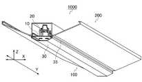
図1は、本実施形態のLED照明器具の一例を示す下方向からの斜視図である。LED照明器具1000は、摩擦低減部を有するLED光源ユニット100、及び本体ユニット200を、主要構成要素として含む。以下では、まず、LED光源ユニット100の構成について説明し、次に、本体ユニット200の構成について説明する。尚、以下で説明するLED光源ユニット及び本体ユニットは、それぞれ、本発明の前記LED光源ユニット及び本体ユニットの説明でもある。[Embodiment 1]
[LED lighting equipment]
FIG. 1 is a perspective view from below showing an example of the LED lighting fixture of the present embodiment. The LED luminaire 1000 includes an LED
[LED光源ユニット]
図2(a)及び(b)は、本実施形態のLED光源ユニットの一例を示す下方向からの斜視図及び上方向からの斜視図である。LED光源ユニット100は、図1のLED光源ユニット100と同一である。LED光源ユニット100は、LED実装基板10、取付部材20、及びカバー部材30を主要構成要素として含み、電源部40を任意の構成要素として含む。[LED light source unit]
2 (a) and 2 (b) are a perspective view from the bottom and a perspective view from the top showing an example of the LED light source unit of the present embodiment. The LED
(1)LED実装基板
LED実装基板10は、図2に示すように、一方の表面(実装面)12にLED11が実装された基板である。図2に示すLED実装基板10では、複数のLED11が前記基板の実装面12に実装されているが、本実施形態において、LED11の数は、これに限定されず、一つであってもよい。また、LED実装基板10は、例えば、配線等の電源接続手段により電源部40と接続されている。尚、本実施形態において、LED実装基板10の後方の端部には、例えば、LED実装基板10と電源部40とを電気的に接続するためのコネクタを実装し、前記コネクタと電源部40とが前記電源接続手段により接続されていてもよい。(1) LED mounting board As shown in FIG. 2, the
本実施形態において、LED実装基板10を構成する基板(単位基板)の数は、一つであってもよいし、複数であってもよい。前記単位基板が複数の場合、LED実装基板10は、例えば、LED実装基板10の長手方向Yに沿って、コネクタ等の接続手段を介して、前記単位基板を互いを接続させることで構成されてもよい。 In the present embodiment, the number of substrates (unit substrates) constituting the
(2)取付部材
図2に示す取付部材20は、取付部材20を収容可能な凹部を有する本体ユニットへの取付部材である。図2に示す取付部材20は、LED実装基板10において、実装面12とは反対側の面に配置される。(2) Mounting member The mounting
図2に示す取付部材20の構成について、図3を用いて説明する。図3は、取付部材20の一例を示す斜視図である。図3に示す取付部材20は、一対の底部21、一対の側壁部22、及び土台部23で構成される。一対の側壁部22により、一対の底部の各底部21及び土台部23が連結されている。各底部21には、LED実装基板10と固定するためのねじ止め孔24が設けられている。これにより、ねじ等の固定手段を用いて、LED実装基板10を取付部材20に取り付ける。各側壁部22には、係止穴25が一つ設けられており、土台部23には、係止穴26が2つ設けられている。これらの係止穴25及び係止穴26は、後述する本体ユニット側に設けられた板バネ状係止片に対する係止穴である。前記板バネ状係止片が、係止穴25及び係止穴26へ係止されることにより、図1のLED照明器具1000に示すように、LED光源ユニット100が、本体ユニット200に取り付けられる。この場合、図1に示すように、使用時において、取付部材20は、本体ユニット200の凹部に収容される。 The configuration of the mounting
(3)カバー部材
図2に示すカバー部材30は、LED実装基板10に対するカバー部材である。使用時において、カバー部材30は、LED実装基板10の実装面12に対する垂直方向Zにおいて、LED実装基板10の実装面及び本体ユニット200の凹部211の開口を覆うように配置される。(3) Cover member The
カバー部材30は、例えば、LED実装基板10の実装面12を覆うカバー部31と、LED実装基板10を収容するレール部32とを含む。尚、本実施形態において、レール部32は、任意の構成要素であり、なくてもよい。 The
カバー部31は、カバー部材30の短手方向Xにおける一対の縁部Hが、短手方向Xにおいて、後述の図4に示す本体ユニット200の凹部211の開口よりも外側に延出する一対の延出領域33を有する。使用時において、本体ユニット200の凹部211の短手方向Xにおける一対の開口縁部Lと、一対の開口縁部Lに対向するカバー部材30の一対の延出領域33とは、それぞれ、LED実装基板10の実装面12に対する垂直方向Zにおいて、長手方向Yに沿って重なり、且つ一対の開口縁部Lと、それに対向するカバー部材30の一対の延出領域33とが、直接的又は間接的に接触している。尚、ここでいう直接的に接触しているとは、例えば、一対の開口縁部Lと、前記対向する一対の延出領域33とが、直接接触する形態をいい、間接的に接触しているとは、一対の開口縁部Lと、前記対向する一対の延出領域33とが、後述のスペーサー等のように別部材を介して接触すする形態をいう。また、直接的又は間接的に接触しているとは、例えば、一対の開口縁部Lと、それに対向するカバー部材30の一対の延出領域33との間に隙間が形成されない形態であるということもできる。 In the
図2に示す一対の延出領域33は、本体ユニット200の一対の開口縁部Lに対向する部分に摩擦低減部35を有する。使用時において、摩擦低減部35により、カバー部材30の一対の延出領域33と本体ユニット200の一対の開口端縁Lとの間で発生する摩擦が低減される。 The pair of extending regions 33 shown in FIG. 2 has a
摩擦低減部35としては、例えば、スペーサーを有してもよい。この場合、前記スペーサーを介して、一対の開口縁部Lと一対の延出領域33とが、間接的に接触している。 The
前記スペーサーとしては、特に制限されず、例えば、粘着テープ等のテープ、ゴム弾性体(エラストマー)シート等が挙げられる。前記テープとしては、特に制限されず、例えば、ガラステープ、金属テープ、樹脂テープ、エラストマーテープ等が挙げられる。前記ガラステープとは、例えば、ガラス繊維を織ったテープ等が挙げられる。前記金属テープとしては、例えば、アルミを薄くしたアルミテープ等が挙げられる。前記樹脂テープとしては、例えば、フッ素樹脂等の樹脂製のテープ等が挙げられる。前記エラストマーテープとしては、例えば、熱可塑性ポリウレタン等の樹脂製のテープ等が挙げられる。前記テープの膜の厚さとしては、特に制限されず、例えば、0.005〜1mmである。前記スペーサーが、テープの場合、例えば、一対の延出領域33の前記対向する部分に前記テープが貼設される。 The spacer is not particularly limited, and examples thereof include a tape such as an adhesive tape and a rubber elastic body (elastomer) sheet. The tape is not particularly limited, and examples thereof include glass tape, metal tape, resin tape, and elastomer tape. Examples of the glass tape include tapes woven with glass fibers. Examples of the metal tape include aluminum tape made by thinning aluminum. Examples of the resin tape include tapes made of resin such as fluororesin. Examples of the elastomer tape include tapes made of resin such as thermoplastic polyurethane. The thickness of the film of the tape is not particularly limited, and is, for example, 0.005 to 1 mm. When the spacer is a tape, for example, the tape is attached to the facing portions of the pair of extension regions 33.
摩擦低減部35としては、例えば、潤滑剤層を有してもよい。この場合、前記潤滑剤層を介して、一対の開口縁部Lと一対の延出領域33とが、間接的に接触している。 The
前記潤滑剤としては、特に制限されず、例えば、潤滑油、グリース、フッ素系樹脂コーティング等が挙げられる。 The lubricant is not particularly limited, and examples thereof include lubricating oil, grease, and a fluororesin coating.
前記潤滑剤層は、例えば、一対の延出領域33の前記対向する部分に、前記潤滑剤を配置することにより形成される。前記潤滑剤を配置する方法は、例えば、塗布等があげられるが、特に制限されず、一般的な公知技術に準じて行うことができる。 The lubricant layer is formed, for example, by arranging the lubricant in the facing portions of the pair of extension regions 33. The method of arranging the lubricant may be, for example, coating, but is not particularly limited and can be carried out according to a general known technique.
摩擦低減部35としては、例えば、表面が凹凸状の粗面層を有してもよい。前記粗面層を介して、例えば、一対の開口縁部Lと前記一対の延出領域33とが、直接又は間接的に接触している。 The
前記粗面層は、例えば、一対の延出領域33の表面層であり、前記表面層は、前記表面が粗面化処理された表面層である。又は、前記粗面層は、例えば、一対の延出領域33の表面層であり、一対の延出領域33が、フィラーを含有する樹脂体である。この場合、一対の開口縁部Lと一対の延出領域33とは、例えば、直接に接触している。 The rough surface layer is, for example, a surface layer of a pair of extension regions 33, and the surface layer is a surface layer whose surface has been roughened. Alternatively, the rough surface layer is, for example, a surface layer of a pair of extension regions 33, and the pair of extension regions 33 is a resin body containing a filler. In this case, the pair of opening edges L and the pair of extending regions 33 are in direct contact with each other, for example.
前記粗面化処理としては、特に制限されず、例えば、表面研削処理、ショットブラスト処理若しくはサンドブラスト処理等のブラスト処理、エンボス加工処理等が挙げられる。前記表面化処理は、前記ブラスト処理であることが好ましい。前記粗面化処理は、一般的な公知技術に準じて行ってもよい。 The roughening treatment is not particularly limited, and examples thereof include a surface grinding treatment, a blasting treatment such as a shot blasting treatment or a sandblasting treatment, and an embossing treatment. The surface treatment is preferably the blast treatment. The roughening treatment may be performed according to a general known technique.
前記樹脂体に含有されるフィラーとしては、例えば、前記樹脂体の表面に凹凸状を形成可能であれば、特に制限されない。前記樹脂体は、例えば、前記フィラーが表面上で凝集することにより、表面が凹凸状の形状を有する。前記フィラーとしては、例えば、無機粒子、有機粒子等が挙げられ、前記無機粒子は、例えば、酸化ケイ素粒子、酸化チタン粒子、酸化アルミニウム粒子等が挙げられ、前記有機粒子は、例えば、ポリメチルメタクリレート樹脂粉末(PMMA粒子)、シリコーン樹脂粉末、ポリスチレン樹脂粉末等が挙げられるこれらの無機粒子および有機粒子は、一種類を単独で使用してもよいし、二種類以上を併用してもよい。前記フィラーを表面上で凝集する方法については、特に制限されず、一般的な公知技術に準じて行えばよい。 The filler contained in the resin body is not particularly limited as long as it can form irregularities on the surface of the resin body, for example. The resin body has a concave-convex shape on the surface, for example, due to the agglomeration of the filler on the surface. Examples of the filler include inorganic particles, organic particles and the like, examples of the inorganic particles include silicon oxide particles, titanium oxide particles, aluminum oxide particles and the like, and the organic particles include, for example, polymethylmethacrylate. As these inorganic particles and organic particles such as resin powder (PMMA particles), silicone resin powder, and polystyrene resin powder, one type may be used alone, or two or more types may be used in combination. The method of agglutinating the filler on the surface is not particularly limited, and may be performed according to a general known technique.
一対のレール部の各レール部32は、一対の延出領域33に対し、起立した状態で配置される。各レール部32は、長手方向Yに沿って、内部に溝34を有する。LED実装基板10は、例えば、各レール部32の溝34にスライド可能に挿入される。使用時において、図1に示すように、一対のレール部32は、本体ユニット200の凹部211に収容される。 Each
カバー部材30は、例えば、LED11からの照射光を透過可能であってもよいし、前記照射光を拡散可能であってもよい。カバー部材30の形成材料としては、特に制限されず、例えば、透過性のポリカーボネート、アクリル樹脂等が挙げられる。 The
カバー部材30のカバー部31の形状は、略逆台形形状であるが、本実施形態において、カバー部の形状は、一対の延出領域33を有するのであれば、これに限定されない。前記カバー部の形状としては、例えば、略凸レンズ形状、略半円形状、略扇形形状、略台形形状等であってもよいし、例示した前記形状を有していてもよい。 The shape of the
本実施形態において、一対のレール部32は、前述の通り、カバー部材30の構成要素として任意の構成要素であり、なくてもよい。カバー部材30の構成要素として、一対のレール部32を含まない場合は、例えば、カバー部31上面に、LED実装基板10を配置し、ねじ等の固定手段を用いて固定してもよい。 In the present embodiment, as described above, the pair of
(4)電源部
電源部40は、例えば、図2に示すように、LED実装基板10の実装面12と反対側の面の略中央部に配置される。(4) Power Supply Unit The
電源部40は、例えば、電源基板及びケースを含み、前記電源基板は、前記ケースに収納される。前記電源基板は、例えば、LED11を駆動するための回路部品が実装された基板であり、電源部40とLED実装基板10とを電気的に接続することにより、LED11を駆動する。 The
(5)サイドキャップ
本実施形態において、LED光源ユニットは、一対のサイドキャップを含んでもよい。前記一対のサイドキャップは、それぞれ、カバー部材30に対するサイドキャップであり、カバー部材30の長手方向Yの端部を挿入する挿入部を有する。使用時において、前記一対のサイドキャップに、それぞれ、カバー部材30の長手方向Yの両端が挿入される。また、前記サイドキャップは、例えば、カバー部材30だけでなく、カバー部材30およびLED実装基板10の基板に対するサイドキャップであってもよい。(5) Side Caps In the present embodiment, the LED light source unit may include a pair of side caps. Each of the pair of side caps is a side cap for the
[本体ユニット]
次に、本実施形態のLED照明器具1000の構成要素である本体ユニット200について図4を用いて説明する。本体ユニット200は、図1の本体ユニット200と同一である。[Main unit]
Next, the
本体ユニット200は、例えば、本体板210、一対の板バネ状係止片220を含む。 The
本体板210は、例えば、長手方向Yに延びる凹部200と、長手方向Yに延びる、凹部200に連結した傾斜面とを有する。凹部200は、その幅方向の断面形状が、凹状であり、前記傾斜面は、その幅方向の断面形状が、上方向に向かって広がるテーパー状である。 The
板バネ状係止片220は、本体板210の長手方向Yの前方の端部側及び後方の端部側のそれぞれに、取り付けられる。板バネ状係止片220は、例えば、先端部222に向かう間に折り返した形状をしており、前記折り返した端部221を有し、折り返した端部221は、カーブ形状を有する。そして、図1に示すように、折り返した端部221が、取付部材20の土台部23の係止穴26を通り、先端部222が、各側壁部22の係止穴25を通ることにより、板バネ状係止片220が取付部材20に係止され、本体ユニット200を、取付部材20に取り付けることが可能である。 The leaf spring-shaped
本体板210及び板バネ状係止片220は、例えば、板金に曲げ加工を施し、不要部分を削ぎ取ることにより形成される。 The
本体ユニット200は、例えば、本体板210の凹部211の底面に、孔(図示せず)を設け、天井材に設けられた吊ボルトを前記孔に通し、前記吊ボルトにナット等の固定手段をねじ込んで、前記天井材に固定される。 The
本体ユニット200は、さらに、端子台を構成要素として備えてもよい。前記端子台は、例えば、本体板210の凹部211の底面213に配置される。前記端子台には、電源部40に電力を供給するために天井材側に露出する電源線が接続されており、さらに、電源部40との間を電気的に接続する電線が接続されていてもよい。 The
以下、図2に示すLED光源ユニット100を、図4に示す本体ユニット200へ取り付けて、図1のLED照明器具をセットする方法について説明する。前述の通り、本体ユニット200の前方の端部及び後方の端部に設けられた各板バネ状係止片220の折り返し端部221を、取付部材20の土台部23の係止穴26に通させ、先端部222を、取付部材20の各側壁22の係止穴25に通させる。これにより、取付部材20は、本体ユニット200の開口部211内に収容される状態で、本体ユニット200に取り付けられる。このとき、本体ユニット200の凹部211の短手方向Xにおける一対の開口縁部Lと、一対の開口縁部Lに対向するカバー部材30の一対の延出領域33とは、それぞれ、LED実装基板10の実装面12に対する垂直方向Zにおいて、長手方向Yに沿って重なる。そして、一対の開口縁部Lと、それに対向するカバー部材30の一対の延出領域33とが、直接的又は間接的に接触している。このようにして、LED光源ユニット100を本体ユニット200へ取りつけ、図1に示すLED照明器具1000をセットすることができる。 Hereinafter, a method of attaching the LED
尚、本実施形態において、本体ユニット200の凹部211の一対の開口縁部Lと、それに対向するカバー部材30の一対の延出領域33とが、直接的又は間接的に接触するように、例えば、板バネ状係止片220を手動で折り曲げる等により、適宜調整してもよい。 In the present embodiment, for example, the pair of opening edges L of the
以下、図1のLED照明器具1000の本体ユニット200を天井材に取り付ける方法の一例を説明する。本体ユニット200に設けられた本体板210の凹部211の底面213の孔(図示せず)に、天井材に設けられた吊ボルトを通し、前記吊ボルトにナット等の固定手段をねじ込んで、前記天井材に固定する。このようにして、図1のLED照明器具1000を天井材に取り付けることができる。 Hereinafter, an example of a method of attaching the
図1に示すLED照明器具では、前述の通り、一対の開口縁部Lと、それに対向するカバー部材30の一対の延出領域33とは、それぞれ、LED実装基板10の実装面12に対する垂直方向Zにおいて、長手方向Yに沿って重なる。そして、一対の開口縁部Lと、それに対向するカバー部材30の一対の延出領域33とが、直接的又は間接的に接触している。これにより、図1に示すLED照明器具1000は、点灯時において、スジ状に暗くなることなく、点灯時における見栄えが良い。 In the LED lighting fixture shown in FIG. 1, as described above, the pair of opening edges L and the pair of extending regions 33 of the
一般的なLED照明器具では、カバー部材の形成材料としては樹脂が用いられており、前記器具本体の形成材料として金属が用いられている。つまり、前記カバー部材及び前記器具本体は、膨張率の異なる材料で形成されている。このため、特許文献1記載のLED照明器具のように、前記直交方向において、前記各延出部が、前記開口端縁と隙間なく重なる場合、点灯時又は消灯時の温度変化により、前記器具本体及び前記カバー部材の接触面で摩擦による音鳴りが発生する。 In a general LED lighting fixture, resin is used as a forming material for a cover member, and metal is used as a forming material for the fixture body. That is, the cover member and the instrument body are made of materials having different expansion coefficients. Therefore, as in the LED lighting fixture described in Patent Document 1, when each of the extending portions overlaps the opening edge without a gap in the orthogonal direction, the fixture main body due to a temperature change when the lighting or extinguishing is performed. In addition, noise is generated due to friction on the contact surface of the cover member.
これに対し、図1に示すLED照明器具では、カバー部材30の一対の延出領域33の前記対向する部分に、摩擦低減部35を有する。そして、摩擦低減部35により、カバー部材30の一対の延出領域33と本体ユニット200の一対の開口縁部Lとの間で発生する摩擦が低減される。これにより、図1に示すLED照明器具1000は、点灯時又は消灯時の温度変化により発生するカバー部材30及び本体ユニット200の開口の端縁の擦れから生じる音鳴りを抑制できる。このため、本発明のLED照明器具は、例えば、前述のような材料の違いに影響を受けることなく、音鳴りを抑制することができる。 On the other hand, the LED luminaire shown in FIG. 1 has a
[実施形態2]
図5は、本実施形態のLED照明器具の一例を示す下方向からの斜視図である。LED照明器具2000は、LED光源ユニット300、及び摩擦低減部を有する本体ユニット400を、主要構成要素として含む。LED照明器具2000は、カバー部材30の一対の延出領域33の前記対向する部分に代えて、器具本体400の凹部211開口縁部Lにおける、一対の延出領域33に対向する部分に摩擦低減部435を有すること以外は、図1に示す前記実施形態1のLED照明器具1000と同一である。[Embodiment 2]
FIG. 5 is a perspective view from below showing an example of the LED lighting fixture of the present embodiment. The
本実施形態においても、まず、器具本体400の一対の開口縁部Lと、それに対向するカバー部材30の一対の延出領域33とが、直接的又は間接的に接触している。そして、摩擦低減部435によって、カバー部材30の一対の延出領域33と本体ユニット400の一対の開口縁部Lとの間で発生する摩擦が低減される。このため、本実施形態のLED照明器具も前記実施形態1同様に、点灯時において、隙間の発生によってスジ状に暗くなる事が無く、見栄えをよくさせるとともに、LED光源ユニット100を点灯又は消灯した時に発生する音鳴りを抑制できる。 Also in the present embodiment, first, the pair of opening edges L of the instrument
摩擦低減部435としては、例えば、スペーサーを有してもよい。この場合、前記スペーサーを介して、一対の開口縁部Lと一対の延出領域33とが、間接的に接触している。前記スペーサーとしては、特に制限されず、例えば、粘着テープ等のテープ等、実施形態1で例示したものが挙げられる。 The
摩擦低減部435としては、例えば、潤滑剤層を有してもよい。この場合、前記潤滑剤層を介して、一対の開口縁部Lと一対の延出領域33とが、間接的に接触している。前記潤滑剤としては、特に制限されず、例えば、実施形態1で例示したものが挙げられる。 The
摩擦低減部435としては、例えば、表面が凹凸形状の粗面層を有してもよい。前記粗面層を介して、例えば、一対の開口縁部Lと一対の延出領域33とが、直接的又は間接的に接触している。 The
前記粗面層は、例えば、一対の開口縁部Lの表面層であり、前記表面層は、前記表面が粗面化処理された表面層である。この場合、一対の開口縁部Lと一対の延出領域33とは、例えば、直接に接触している。前記粗面化処理としては、特に制限されず、例えば、実施形態1で例示したものが挙げられる。 The rough surface layer is, for example, a surface layer of a pair of opening edge portions L, and the surface layer is a surface layer whose surface has been roughened. In this case, the pair of opening edges L and the pair of extending regions 33 are in direct contact with each other, for example. The roughening treatment is not particularly limited, and examples thereof include those exemplified in the first embodiment.
[実施形態3]
本実施形態のLED照明器具は、前述の通り、前記摩擦低減部を有する本発明のLED光源ユニット及び本体ユニットの双方を備える形態である。図6は、本実施形態のLED照明器具の一例を示す下方向からの斜視図である。本実施形態のLED照明器具3000は、摩擦低減部を有するLED光源ユニット100及び本体ユニット400を主要構成要素として含む。図6に示すLED光源ユニット100は、図1に示す前記実施形態1のLED光源ユニット100と同一であり、図6に示す本体ユニット400は、図5に示す前記実施形態2の本体ユニット400と同一である。[Embodiment 3]
As described above, the LED lighting fixture of the present embodiment is a form including both the LED light source unit and the main body unit of the present invention having the friction reducing portion. FIG. 6 is a perspective view from below showing an example of the LED lighting fixture of the present embodiment. The
本実施形態において、一対の延出領域33側の摩擦低減部35及び開口縁部L側の摩擦低減部435の構成は同一であってもよいし、異なっていてもよい。 In the present embodiment, the configurations of the pair of
本実施形態においても、まず、器具本体400の一対の開口縁部Lと、それに対向するカバー部材30の一対の延出領域33とが、直接的又は間接的に接触している。そして、摩擦低減部435によって、カバー部材30の一対の延出領域33と本体ユニット400の一対の開口縁部Lとの間で発生する摩擦が低減される。このため、本実施形態のLED照明器具も前記実施形態1及び前記実施形態2と同様に、点灯時において、隙間の発生によってスジ状に暗くなる事が無く、見栄えをよくさせるとともに、LED光源ユニット100を点灯又は消灯した時に発生する音鳴りを抑制できる。 Also in the present embodiment, first, the pair of opening edges L of the instrument
本発明において、取付部材及びカバー部材の構成は、図2に示す前記実施形態1の取付部材20及びカバー部材30の構成に限定されない。前記取付部材としては、具体的には、例えば、図3に示す取付部材20に代えて、LED実装基板10を搭載可能な長尺状の搭載面を有し、且つ本体ユニット200に取りつけ可能な係止部を有する構成としてもよい。前記カバー部材としては、具体的には、例えば、図2に示すカバー部材30の構成要素である一対のレール部32に代えて、カバー部材に取りつけ可能な一対の突起部を設けた構成としてもよい。前記突起部は、例えば、一対の延出領域33に対し垂直方向に起立した状態で配置され、前記突起部が、取付部材20と係止若しくは嵌合することにより、前記カバー部材に取り付けられる構成としてもよい。この場合、前記一対の突起部は、例えば、使用時において、本体ユニット200の凹部211に収容される。 In the present invention, the configurations of the mounting member and the cover member are not limited to the configurations of the mounting
本発明のLED照明器具は、台所、オフィス等の天井用照明器具としても利用でき、倉庫、工場等の大規模空間の高天井用照明器具としても好適に使用することが出来る。 The LED lighting fixture of the present invention can also be used as a ceiling lighting fixture for kitchens, offices, etc., and can also be suitably used as a high ceiling lighting fixture for large-scale spaces such as warehouses and factories.
以上、実施形態を参照して本発明を説明したが、本発明は、上記実施形態に限定されるものではない。本発明の構成や詳細には、本発明のスコープ内で当業者が理解しうる様々な変更をすることができる。 Although the present invention has been described above with reference to the embodiments, the present invention is not limited to the above embodiments. Various changes that can be understood by those skilled in the art can be made to the structure and details of the present invention within the scope of the present invention.
10 LED実装基板
11 LED
12 実装面
20 取付部材
21 底部
22 側壁部
23 土台部
24 ねじ止め孔
25、26 係止穴
30 カバー部材
31 カバー部
32 レール部
33 延出領域
35、435 摩擦低減部
40 電源部
100、300 LED光源ユニット
200、400 本体ユニット
210 本体板
220 板バネ状係止片
211 凹部
212 底面
221 折り返し端部
222 先端部
1000、2000、3000 LED照明器具10
12
Claims (16)
Translated fromJapanese前記LED実装基板は、一方の表面にLEDが実装された基板であり、
前記取付部材は、前記取付部材を収容可能な凹部を有する本体ユニットへの取付部材であり、前記LED実装基板を前記取付部材に取り付けるための一対の底部と、前記一対の底部から夫々起立した一対の側壁部と、前記側壁部の一端同士を結ぶ土台部とを有し、前記LED実装基板における実装面とは反対側の面の長手方向両端寄りに一対が配置され、
前記側壁部及び前記土台部は、板バネ状係止片に対する係止穴を有し、
前記板バネ状係止片は、先端部に向かう間に折り返した形状をした端部を有し、前記端部は、カーブ形状を有し、
前記カバー部材は、前記LED実装基板の実装面を覆うカバー部と前記LED実装基板を収容するレール部とを含み、前記カバー部の短手方向における一対の縁部が、短手方向において、前記本体ユニットの凹部の開口よりも外側に延出する一対の延出領域を有し、
前記カバー部の一対の延出領域は、前記本体ユニットの一対の開口縁部に対向する部分で前記レール部の短手方向の外側に、摩擦低減部を有し、
使用時において、
前記取付部材は、前記本体ユニットの凹部の長手方向の両端寄りに前記一対が収容され、
前記カバー部材は、前記LED実装基板の実装面に対する垂直方向において、前記LED実装基板の実装面及び前記本体ユニットの凹部の開口を覆うように配置され、
前記本体ユニットの凹部の短手方向における一対の開口縁部と、前記一対の開口縁部に対向する前記カバー部の一対の延出領域とは、それぞれ、前記LED実装基板の実装面に対する垂直方向において、長手方向に沿って重なり、且つ前記一対の開口縁部と、それに対向する前記カバー部の前記一対の延出領域とが、直接的又は間接的に接触しており、
前記摩擦低減部によって、前記カバー部の一対の延出領域と前記本体ユニットの一対の開口縁部との間で発生する摩擦が低減されることを特徴とするLED光源ユニット。Including LED mounting board, mounting member, and cover member
The LED mounting board is a board on which an LED is mounted on one surface.
The mounting member is a mounting member for a main body unit having a recess capable of accommodating the mounting member, and is a pair of bottoms for mounting the LED mounting board on the mounting member and a pair of rising portions from the pair of bottoms. A pair of side wall portions and a base portion connecting one ends of the side wall portions are arranged near both ends in the longitudinal direction of a surface of the LED mounting substrate opposite to the mounting surface.
The side wall portion and the base portion have a locking hole for a leaf spring-shaped locking piece.
The leaf spring-shaped locking piece has an end portion that is folded back toward the tip portion, and the end portion has a curved shape.
The cover member includes a cover portion that covers the mounting surface of the LED mounting substrate and a rail portion that accommodates the LED mounting substrate, and a pair of edge portions of the cover portion in the lateral direction are formed in the lateral direction. It has a pair of extension areas that extend outward from the opening of the recess of the main unit.
The pair of extending regions of the cover portion has a friction reducing portion on the outer side of the rail portion in the lateral direction at a portion facing the pair of opening edges of the main body unit.
At the time of use
The pair of mounting members is housed near both ends of the recess in the main body unit in the longitudinal direction.
The cover member is arranged so as to cover the mounting surface of the LED mounting board and the opening of the recess of the main body unit in the direction perpendicular to the mounting surface of the LED mounting board.
The pair of opening edges in the lateral direction of the recesses of the main body unit and the pair of extending regions of the cover portion facing the pair of opening edges are respectively in the direction perpendicular to the mounting surface of the LED mounting substrate. In the above, the pair of opening edges overlapping along the longitudinal direction and the pair of extending regions of the cover portion facing the pair are in direct or indirect contact with each other.
An LED light source unit characterized in that the friction reducing portion reduces friction generated between a pair of extending regions of the cover portion and a pair of opening edges of the main body unit.
前記スペーサーを介して、前記一対の開口縁部と前記一対の延出領域とが、間接的に接触している、請求項1記載のLED光源ユニット。A spacer is provided as the friction reducing portion.
The LED light source unit according to claim 1, wherein the pair of opening edges and the pair of extending regions are indirectly in contact with each other via the spacer.
前記潤滑剤層を介して、前記一対の開口縁部と前記一対の延出領域とが、間接的に接触している、請求項1から3のいずれか一項に記載のLED光源ユニット。A lubricant layer is provided as the friction reducing portion.
The LED light source unit according to any one of claims 1 to 3, wherein the pair of opening edges and the pair of extending regions are indirectly in contact with each other via the lubricant layer.
前記粗面層を介して、前記一対の開口縁部と前記一対の延出領域とが、直接的又は間接的に接触している、請求項1から4のいずれか一項に記載のLED光源ユニット。As the friction reducing portion, a rough surface layer having an uneven surface is provided.
The LED light source according to any one of claims 1 to 4, wherein the pair of opening edges and the pair of extending regions are in direct or indirect contact with each other via the rough surface layer. unit.
前記本体ユニットは、本体板、及び一対の板バネ状係止片を含み、
前記本体板は、長手方向に延びる凹部と、長手方向に延びる、前記凹部に連結した傾斜面とを有し、
前記板バネ状係止片は、先端部に向かう間に折り返した形状をした端部を有し、前記端部は、カーブ形状を有し、前記板バネ状係止片は、前記本体板の長手方向の前方の端部側及び後方の端部側のそれぞれに、配置され、
前記本体ユニットに取付けられるLED光源ユニットは、
LED実装基板、取付部材、及びカバー部材を含み、
前記LED実装基板は、一方の表面にLEDが実装された基板であり、
前記取付部材は、前記取付部材を収容可能な凹部を有する本体ユニットへの取付部材であり、前記LED実装基板を前記取付部材に取り付けるための一対の底部と、前記一対の底部から夫々起立した一対の側壁部と、前記側壁部の一端同士を結ぶ土台部とを有し、前記LED実装基板における実装面とは反対側の面の長手方向両端寄りに一対が配置され、
前記側壁部及び前記土台部は、前記板バネ状係止片に対する係止穴を有し、
前記カバー部材は、前記LED実装基板の実装面を覆うカバー部と前記LED実装基板を収容するレール部とを含み、前記カバー部の短手方向における一対の縁部が、短手方向において、前記本体の凹部の開口よりも外側に延出する一対の延出領域を有し、
前記凹部の短手方向における一対の開口縁部は、前記カバー部の一対の延出領域に対向する部分で前記レール部の短手方向の外側に、摩擦低減部を有し、
使用時において、
前記取付部材は、前記本体ユニットの凹部の長手方向の両端寄りに前記一対が収容され、
前記カバー部材は、前記LED実装基板の実装面に対する垂直方向において、前記LED実装基板の実装面及び前記本体ユニットの凹部の開口を覆うように配置され、
前記本体ユニットの凹部の短手方向における一対の開口縁部と、前記一対の開口縁部に対向する前記カバー部の一対の延出領域とは、それぞれ、前記LED実装基板の実装面に対する垂直方向において、長手方向に沿って重なり、且つ前記一対の開口縁部と、それに対向する前記カバー部の前記一対の延出領域とが、直接的又は間接的に接触しており、
前記摩擦低減部によって、前記カバー部の一対の延出領域と前記本体ユニットの一対の開口縁部との間で発生する摩擦が低減されることを特徴とするLED照明器具の本体ユニット。It is a main body unit that has a recess for mounting the LED light source unit.
The main body unit includes a main body plate and a pair of leaf spring-like locking pieces.
The main body plate has a recess extending in the longitudinal direction and an inclined surface extending in the longitudinal direction and connected to the recess.
The leaf spring-shaped locking piece has an end portion that is folded back toward the tip portion, the end portion has a curved shape, and the leaf spring-shaped locking piece is the main body plate. Arranged on each of the front end side and the rear end side in the longitudinal direction,
The LED light source unit attached to the main body unit is
Including LED mounting board, mounting member, and cover member
The LED mounting board is a board on which an LED is mounted on one surface.
The mounting member is a mounting member for a main body unit having a recess capable of accommodating the mounting member, and is a pair of bottoms for mounting the LED mounting board on the mounting member and a pair of rising portions from the pair of bottoms. A pair of side wall portions and a base portion connecting one ends of the side wall portions are arranged near both ends in the longitudinal direction of a surface of the LED mounting substrate opposite to the mounting surface.
The side wall portion and the base portion have a locking hole for the leaf spring-shaped locking piece.
The cover member includes a cover portion that covers the mounting surface of the LED mounting substrate and a rail portion that accommodates the LED mounting substrate, and a pair of edge portions of the cover portion in the lateral direction are formed in the lateral direction. It has a pair of extension areas that extend outward from the opening of the recess in the body.
The pair of opening edges of the recess in the lateral direction have a friction reducing portion on the outer side of the rail portion in the lateral direction at a portion facing the pair of extending regions of the cover portion.
At the time of use
The pair of mounting members is housed near both ends of the recess in the main body unit in the longitudinal direction.
The cover member is arranged so as to cover the mounting surface of the LED mounting board and the opening of the recess of the main body unit in the direction perpendicular to the mounting surface of the LED mounting board.
The pair of opening edges in the lateral direction of the recesses of the main body unit and the pair of extending regions of the cover portion facing the pair of opening edges are respectively in the direction perpendicular to the mounting surface of the LED mounting substrate. In the above, the pair of opening edges overlapping along the longitudinal direction and the pair of extending regions of the cover portion facing the pair are in direct or indirect contact with each other.
A main body unit of an LED lighting fixture, characterized in that the friction reducing portion reduces friction generated between a pair of extending regions of the cover portion and a pair of opening edges of the main body unit.
前記スペーサーを介して、前記一対の開口縁部と前記一対の延出領域とが、間接的に接触している、請求項8記載の本体ユニット。A spacer is provided as the friction reducing portion.
The main body unit according to claim 8, wherein the pair of opening edges and the pair of extending regions are indirectly in contact with each other via the spacer.
前記潤滑剤層を介して、前記一対の開口縁部と前記一対の延出領域とが、間接的に接触している、請求項8から10のいずれか一項に記載の本体ユニット。A lubricant layer is provided as the friction reducing portion.
The main body unit according to any one of claims 8 to 10, wherein the pair of opening edges and the pair of extending regions are indirectly in contact with each other via the lubricant layer.
前記粗面層を介して、前記一対の開口縁部と前記一対の延出領域とが、直接的又は間接的 に接触している、請求項8から11のいずれか一項に記載の本体ユニット。As the friction reducing portion, a rough surface layer having an uneven surface is provided.
The main body unit according to any one of claims 8 to 11, wherein the pair of opening edges and the pair of extending regions are in direct or indirect contact with each other through the rough surface layer. ..
前記LED光源ユニットは、
LED実装基板、取付部材、及びカバー部材を含み、
前記LED実装基板は、一方の表面にLEDが実装された基板であり、
前記取付部材は、前記取付部材を収容可能な凹部を有する本体ユニットへの取付部材であり、前記LED実装基板を前記取付部材に取り付けるための一対の底部と、前記一対の底部から夫々起立した一対の側壁部と、前記側壁部の一端同士を結ぶ土台部とを有し、前記LED実装基板における実装面とは反対側の面の長手方向両端寄りに一対が配置され、
前記側壁部及び前記土台部は、板バネ状係止片に対する係止穴を有し、
前記カバー部材は、前記LED実装基板の実装面を覆うカバー部と前記LED実装基板を収容するレール部とを含み、前記カバー部の短手方向における一対の縁部が、短手方向において、前記本体ユニットの凹部の開口よりも外側に延出する一対の延出領域を有し、
前記本体ユニットは、
前記LED光源ユニットを取り付けるための凹部、本体板、一対の前記板バネ状係止片を含み、
前記本体板は、長手方向に延びる凹部と、長手方向に延びる、前記凹部に連結した傾斜面とを有し、
前記板バネ状係止片は、先端部に向かう間に折り返した形状をした端部を有し、前記端部は、カーブ形状を有し、前記板バネ状係止片は、前記本体板の長手方向の前方の端部側及び後方の端部側のそれぞれに、配置され、
前記カバー部の一対の延出領域であって、前記本体ユニットの一対の開口縁部に対向する部分、及び、前記本体ユニットの凹部の短手方向における一対の開口縁部であって、前記カバー部の一対の延出領域に対向する部分の少なくとも一方が、前記レール部の短手方向の外側に摩擦低減部を有しており、
使用時において、
前記LED光源ユニットの前記取付部材は、前記本体ユニットの凹部の長手方向の両端寄りに前記一対が収容され、
前記カバー部材は、前記LED実装基板の実装面に対する垂直方向において、前記LED実装基板の実装面及び前記本体ユニットの凹部の開口を覆うように配置され、
前記本体ユニットの凹部の短手方向における一対の開口縁部と、前記一対の開口縁部に対向する前記カバー部の一対の延出領域とは、それぞれ、前記LED実装基板の実装面に対する垂直方向において、長手方向に沿って重なり、且つ前記一対の開口縁部と、それに対向する前記カバー部の前記一対の延出領域とが、直接的又は間接的に接触しており、
前記摩擦低減部によって、前記カバー部の一対の延出領域と前記本体ユニットの一対の開口縁部との間で発生する摩擦が低減されることを特徴とするLED照明器具。Including LED light source unit and main body unit
The LED light source unit is
Including LED mounting board, mounting member, and cover member
The LED mounting board is a board on which an LED is mounted on one surface.
The mounting member is a mounting member for a main body unit having a recess capable of accommodating the mounting member, and is a pair of bottoms for mounting the LED mounting board on the mounting member and a pair of rising portions from the pair of bottoms. A pair of side wall portions and a base portion connecting one ends of the side wall portions are arranged near both ends in the longitudinal direction of a surface of the LED mounting substrate opposite to the mounting surface.
The side wall portion and the base portion have a locking hole for a leaf spring-shaped locking piece.
The cover member includes a cover portion that covers the mounting surface of the LED mounting substrate and a rail portion that accommodates the LED mounting substrate, and a pair of edge portions of the cover portion in the lateral direction are formed in the lateral direction. It has a pair of extension areas that extend outward from the opening of the recess of the main unit.
The main body unit
Includes a recess for mounting the LED light source unit, a body plate, and a pair of leaf spring-like locking pieces.
The main body plate has a recess extending in the longitudinal direction and an inclined surface extending in the longitudinal direction and connected to the recess.
The leaf spring-shaped locking piece has an end portion that is folded back toward the tip portion, the end portion has a curved shape, and the leaf spring-shaped locking piece is the main body plate. Arranged on each of the front end side and the rear end side in the longitudinal direction,
A pair of extending regions of the cover portion, a portion facing the pair of opening edges of the main body unit, and a pair of opening edges of the concave portion of the main body unit in the lateral direction. At least one of the portions facing the pair of extension regions of the portions has a friction reducing portion on the outer side of the rail portion in the lateral direction.
At the time of use
The pair of the mounting members of the LED light source unit is housed near both ends of the recess of the main body unit in the longitudinal direction.
The cover member is arranged so as to cover the mounting surface of the LED mounting board and the opening of the recess of the main body unit in the direction perpendicular to the mounting surface of the LED mounting board.
The pair of opening edges in the lateral direction of the recesses of the main body unit and the pair of extending regions of the cover portion facing the pair of opening edges are respectively in the direction perpendicular to the mounting surface of the LED mounting substrate. In the above, the pair of opening edges overlapping along the longitudinal direction and the pair of extending regions of the cover portion facing the pair are in direct or indirect contact with each other.
An LED lighting fixture characterized in that the friction reducing portion reduces friction generated between a pair of extending regions of the cover portion and a pair of opening edges of the main body unit.
The LED lighting fixture according to claim 14 or 15, wherein the main body unit is the main body unit according to any one of claims 8 to 13.
Priority Applications (1)
| Application Number | Priority Date | Filing Date | Title |
|---|---|---|---|
| JP2019155048AJP6806862B2 (en) | 2019-08-27 | 2019-08-27 | LED light source unit, main unit, and LED lighting equipment |
Applications Claiming Priority (1)
| Application Number | Priority Date | Filing Date | Title |
|---|---|---|---|
| JP2019155048AJP6806862B2 (en) | 2019-08-27 | 2019-08-27 | LED light source unit, main unit, and LED lighting equipment |
Related Parent Applications (1)
| Application Number | Title | Priority Date | Filing Date |
|---|---|---|---|
| JP2015056775ADivisionJP6580352B2 (en) | 2015-03-19 | 2015-03-19 | LED light source unit, main unit, and LED lighting apparatus |
Publications (2)
| Publication Number | Publication Date |
|---|---|
| JP2019197746A JP2019197746A (en) | 2019-11-14 |
| JP6806862B2true JP6806862B2 (en) | 2021-01-06 |
Family
ID=68538572
Family Applications (1)
| Application Number | Title | Priority Date | Filing Date |
|---|---|---|---|
| JP2019155048AActiveJP6806862B2 (en) | 2019-08-27 | 2019-08-27 | LED light source unit, main unit, and LED lighting equipment |
Country Status (1)
| Country | Link |
|---|---|
| JP (1) | JP6806862B2 (en) |
Family Cites Families (5)
| Publication number | Priority date | Publication date | Assignee | Title |
|---|---|---|---|---|
| JP2001210133A (en)* | 2000-01-24 | 2001-08-03 | Matsushita Electric Works Ltd | Electric light fixture |
| JP4360478B2 (en)* | 2000-12-21 | 2009-11-11 | 株式会社エンプラス | Surface light source device and image display device |
| JP5610622B2 (en)* | 2010-08-31 | 2014-10-22 | パナソニック株式会社 | lighting equipment |
| JP5971591B2 (en)* | 2012-10-11 | 2016-08-17 | パナソニックIpマネジメント株式会社 | lighting equipment |
| JP6016163B2 (en)* | 2013-03-25 | 2016-10-26 | パナソニックIpマネジメント株式会社 | lighting equipment |
- 2019
- 2019-08-27JPJP2019155048Apatent/JP6806862B2/enactiveActive
Also Published As
| Publication number | Publication date |
|---|---|
| JP2019197746A (en) | 2019-11-14 |
Similar Documents
| Publication | Publication Date | Title |
|---|---|---|
| US9388958B2 (en) | Wall washing lamp | |
| JP2014179209A (en) | Lighting fixture | |
| JP2015176747A (en) | Light source unit and lighting fixture using the same | |
| JP6580352B2 (en) | LED light source unit, main unit, and LED lighting apparatus | |
| JP5971591B2 (en) | lighting equipment | |
| JP6806862B2 (en) | LED light source unit, main unit, and LED lighting equipment | |
| TW201632780A (en) | Retrofit kit for recessed light fixtures and retrofitting method | |
| JP5732613B2 (en) | lighting equipment | |
| JP6762400B2 (en) | LED light source unit, main unit, and LED lighting equipment | |
| WO2009014387A2 (en) | Stick-type led lighting apparatus | |
| JP6528235B2 (en) | LED light source unit, body unit, and LED lighting apparatus | |
| JP6692066B2 (en) | lighting equipment | |
| JP6238164B2 (en) | LED lighting fixtures | |
| JP6602083B2 (en) | Lighting device | |
| JP2005279102A (en) | Toilet rack with mirror | |
| JP2014078511A (en) | Light source unit and lighting fixture | |
| JP6722879B2 (en) | Light source unit and lighting equipment | |
| CN222047457U (en) | A downward emitting wall lamp | |
| JP2020140815A (en) | Lighting device | |
| KR101524841B1 (en) | Detachable led lighting fixtures | |
| KR0135404Y1 (en) | Fluorescent lamp | |
| JP2014137932A (en) | Light source device and lighting fixture using the same | |
| JP2019096384A (en) | Lighting device | |
| JP7531270B2 (en) | Mounting fixture | |
| JP4915936B2 (en) | lighting equipment |
Legal Events
| Date | Code | Title | Description |
|---|---|---|---|
| A521 | Request for written amendment filed | Free format text:JAPANESE INTERMEDIATE CODE: A523 Effective date:20190924 | |
| A621 | Written request for application examination | Free format text:JAPANESE INTERMEDIATE CODE: A621 Effective date:20190924 | |
| A977 | Report on retrieval | Free format text:JAPANESE INTERMEDIATE CODE: A971007 Effective date:20200622 | |
| A131 | Notification of reasons for refusal | Free format text:JAPANESE INTERMEDIATE CODE: A131 Effective date:20200707 | |
| TRDD | Decision of grant or rejection written | ||
| A01 | Written decision to grant a patent or to grant a registration (utility model) | Free format text:JAPANESE INTERMEDIATE CODE: A01 Effective date:20201117 | |
| A61 | First payment of annual fees (during grant procedure) | Free format text:JAPANESE INTERMEDIATE CODE: A61 Effective date:20201204 | |
| R150 | Certificate of patent or registration of utility model | Ref document number:6806862 Country of ref document:JP Free format text:JAPANESE INTERMEDIATE CODE: R150 | |
| S531 | Written request for registration of change of domicile | Free format text:JAPANESE INTERMEDIATE CODE: R313531 | |
| R350 | Written notification of registration of transfer | Free format text:JAPANESE INTERMEDIATE CODE: R350 | |
| R250 | Receipt of annual fees | Free format text:JAPANESE INTERMEDIATE CODE: R250 | |
| R250 | Receipt of annual fees | Free format text:JAPANESE INTERMEDIATE CODE: R250 |