JP6804325B2 - Liquid treatment equipment - Google Patents
Liquid treatment equipmentDownload PDFInfo
- Publication number
- JP6804325B2 JP6804325B2JP2017022350AJP2017022350AJP6804325B2JP 6804325 B2JP6804325 B2JP 6804325B2JP 2017022350 AJP2017022350 AJP 2017022350AJP 2017022350 AJP2017022350 AJP 2017022350AJP 6804325 B2JP6804325 B2JP 6804325B2
- Authority
- JP
- Japan
- Prior art keywords
- liquid
- substrate
- liquid supply
- discharge port
- wafer
- Prior art date
- Legal status (The legal status is an assumption and is not a legal conclusion. Google has not performed a legal analysis and makes no representation as to the accuracy of the status listed.)
- Active
Links
Images


Classifications
- H—ELECTRICITY
- H01—ELECTRIC ELEMENTS
- H01L—SEMICONDUCTOR DEVICES NOT COVERED BY CLASS H10
- H01L21/00—Processes or apparatus adapted for the manufacture or treatment of semiconductor or solid state devices or of parts thereof
- H01L21/67—Apparatus specially adapted for handling semiconductor or electric solid state devices during manufacture or treatment thereof; Apparatus specially adapted for handling wafers during manufacture or treatment of semiconductor or electric solid state devices or components ; Apparatus not specifically provided for elsewhere
- H01L21/67005—Apparatus not specifically provided for elsewhere
- H01L21/67011—Apparatus for manufacture or treatment
- H01L21/67017—Apparatus for fluid treatment
- H01L21/67063—Apparatus for fluid treatment for etching
- H01L21/67075—Apparatus for fluid treatment for etching for wet etching
- H01L21/6708—Apparatus for fluid treatment for etching for wet etching using mainly spraying means, e.g. nozzles
- H—ELECTRICITY
- H01—ELECTRIC ELEMENTS
- H01L—SEMICONDUCTOR DEVICES NOT COVERED BY CLASS H10
- H01L21/00—Processes or apparatus adapted for the manufacture or treatment of semiconductor or solid state devices or of parts thereof
- H01L21/67—Apparatus specially adapted for handling semiconductor or electric solid state devices during manufacture or treatment thereof; Apparatus specially adapted for handling wafers during manufacture or treatment of semiconductor or electric solid state devices or components ; Apparatus not specifically provided for elsewhere
- H01L21/67005—Apparatus not specifically provided for elsewhere
- H01L21/67011—Apparatus for manufacture or treatment
- H01L21/67017—Apparatus for fluid treatment
- H01L21/67028—Apparatus for fluid treatment for cleaning followed by drying, rinsing, stripping, blasting or the like
- H01L21/67034—Apparatus for fluid treatment for cleaning followed by drying, rinsing, stripping, blasting or the like for drying
- H—ELECTRICITY
- H01—ELECTRIC ELEMENTS
- H01L—SEMICONDUCTOR DEVICES NOT COVERED BY CLASS H10
- H01L21/00—Processes or apparatus adapted for the manufacture or treatment of semiconductor or solid state devices or of parts thereof
- H01L21/67—Apparatus specially adapted for handling semiconductor or electric solid state devices during manufacture or treatment thereof; Apparatus specially adapted for handling wafers during manufacture or treatment of semiconductor or electric solid state devices or components ; Apparatus not specifically provided for elsewhere
- H01L21/67005—Apparatus not specifically provided for elsewhere
- H01L21/67011—Apparatus for manufacture or treatment
- H01L21/67017—Apparatus for fluid treatment
- H01L21/67028—Apparatus for fluid treatment for cleaning followed by drying, rinsing, stripping, blasting or the like
- H01L21/6704—Apparatus for fluid treatment for cleaning followed by drying, rinsing, stripping, blasting or the like for wet cleaning or washing
- H01L21/67051—Apparatus for fluid treatment for cleaning followed by drying, rinsing, stripping, blasting or the like for wet cleaning or washing using mainly spraying means, e.g. nozzles
- H—ELECTRICITY
- H01—ELECTRIC ELEMENTS
- H01L—SEMICONDUCTOR DEVICES NOT COVERED BY CLASS H10
- H01L21/00—Processes or apparatus adapted for the manufacture or treatment of semiconductor or solid state devices or of parts thereof
- H01L21/67—Apparatus specially adapted for handling semiconductor or electric solid state devices during manufacture or treatment thereof; Apparatus specially adapted for handling wafers during manufacture or treatment of semiconductor or electric solid state devices or components ; Apparatus not specifically provided for elsewhere
- H01L21/67005—Apparatus not specifically provided for elsewhere
- H01L21/67011—Apparatus for manufacture or treatment
- H01L21/6715—Apparatus for applying a liquid, a resin, an ink or the like
- H—ELECTRICITY
- H01—ELECTRIC ELEMENTS
- H01L—SEMICONDUCTOR DEVICES NOT COVERED BY CLASS H10
- H01L21/00—Processes or apparatus adapted for the manufacture or treatment of semiconductor or solid state devices or of parts thereof
- H01L21/67—Apparatus specially adapted for handling semiconductor or electric solid state devices during manufacture or treatment thereof; Apparatus specially adapted for handling wafers during manufacture or treatment of semiconductor or electric solid state devices or components ; Apparatus not specifically provided for elsewhere
- H01L21/683—Apparatus specially adapted for handling semiconductor or electric solid state devices during manufacture or treatment thereof; Apparatus specially adapted for handling wafers during manufacture or treatment of semiconductor or electric solid state devices or components ; Apparatus not specifically provided for elsewhere for supporting or gripping
- H01L21/687—Apparatus specially adapted for handling semiconductor or electric solid state devices during manufacture or treatment thereof; Apparatus specially adapted for handling wafers during manufacture or treatment of semiconductor or electric solid state devices or components ; Apparatus not specifically provided for elsewhere for supporting or gripping using mechanical means, e.g. chucks, clamps or pinches
- H01L21/68714—Apparatus specially adapted for handling semiconductor or electric solid state devices during manufacture or treatment thereof; Apparatus specially adapted for handling wafers during manufacture or treatment of semiconductor or electric solid state devices or components ; Apparatus not specifically provided for elsewhere for supporting or gripping using mechanical means, e.g. chucks, clamps or pinches the wafers being placed on a susceptor, stage or support
- H01L21/68764—Apparatus specially adapted for handling semiconductor or electric solid state devices during manufacture or treatment thereof; Apparatus specially adapted for handling wafers during manufacture or treatment of semiconductor or electric solid state devices or components ; Apparatus not specifically provided for elsewhere for supporting or gripping using mechanical means, e.g. chucks, clamps or pinches the wafers being placed on a susceptor, stage or support characterised by a movable susceptor, stage or support, others than those only rotating on their own vertical axis, e.g. susceptors on a rotating caroussel
- H—ELECTRICITY
- H01—ELECTRIC ELEMENTS
- H01L—SEMICONDUCTOR DEVICES NOT COVERED BY CLASS H10
- H01L21/00—Processes or apparatus adapted for the manufacture or treatment of semiconductor or solid state devices or of parts thereof
- H01L21/67—Apparatus specially adapted for handling semiconductor or electric solid state devices during manufacture or treatment thereof; Apparatus specially adapted for handling wafers during manufacture or treatment of semiconductor or electric solid state devices or components ; Apparatus not specifically provided for elsewhere
- H01L21/683—Apparatus specially adapted for handling semiconductor or electric solid state devices during manufacture or treatment thereof; Apparatus specially adapted for handling wafers during manufacture or treatment of semiconductor or electric solid state devices or components ; Apparatus not specifically provided for elsewhere for supporting or gripping
- H01L21/687—Apparatus specially adapted for handling semiconductor or electric solid state devices during manufacture or treatment thereof; Apparatus specially adapted for handling wafers during manufacture or treatment of semiconductor or electric solid state devices or components ; Apparatus not specifically provided for elsewhere for supporting or gripping using mechanical means, e.g. chucks, clamps or pinches
- H01L21/68714—Apparatus specially adapted for handling semiconductor or electric solid state devices during manufacture or treatment thereof; Apparatus specially adapted for handling wafers during manufacture or treatment of semiconductor or electric solid state devices or components ; Apparatus not specifically provided for elsewhere for supporting or gripping using mechanical means, e.g. chucks, clamps or pinches the wafers being placed on a susceptor, stage or support
- H01L21/68792—Apparatus specially adapted for handling semiconductor or electric solid state devices during manufacture or treatment thereof; Apparatus specially adapted for handling wafers during manufacture or treatment of semiconductor or electric solid state devices or components ; Apparatus not specifically provided for elsewhere for supporting or gripping using mechanical means, e.g. chucks, clamps or pinches the wafers being placed on a susceptor, stage or support characterised by the construction of the shaft
Landscapes
- Engineering & Computer Science (AREA)
- Physics & Mathematics (AREA)
- Condensed Matter Physics & Semiconductors (AREA)
- General Physics & Mathematics (AREA)
- Manufacturing & Machinery (AREA)
- Computer Hardware Design (AREA)
- Microelectronics & Electronic Packaging (AREA)
- Power Engineering (AREA)
- Cleaning Or Drying Semiconductors (AREA)
Description
Translated fromJapanese開示の実施形態は、液処理装置に関する。 The disclosed embodiment relates to a liquid treatment device.
従来、基板の下面に流体を供給するノズルユニットを有する液処理装置が知られている(例えば、特許文献1参照)。 Conventionally, a liquid treatment apparatus having a nozzle unit for supplying a fluid to the lower surface of a substrate is known (see, for example, Patent Document 1).
しかしながら、上記液処理装置では、基板の下面に向けて吐出された液が、ノズルユニットの中心側の上端面に残ることがある。この場合、上端面に残った液が基板の下面に付着するおそれがある。 However, in the liquid treatment apparatus, the liquid discharged toward the lower surface of the substrate may remain on the upper end surface on the center side of the nozzle unit. In this case, the liquid remaining on the upper end surface may adhere to the lower surface of the substrate.
実施形態の一態様は、基板の下面に向けて吐出された液が、ノズルユニットの中心側の上端面に残ることを抑制する液処理装置を提供することを目的とする。 One aspect of the embodiment is to provide a liquid treatment device that suppresses the liquid discharged toward the lower surface of the substrate from remaining on the upper end surface on the center side of the nozzle unit.
実施形態の一態様に係る液処理装置は、基板保持部と、駆動部と、軸部と、ノズルとを備える。基板保持部は、基板を水平に保持する。駆動部は、基板保持部によって基板が保持された状態で、基板および基板保持部を回転させる。軸部は、基板保持部に保持された基板の回転軸を含み、回転軸の軸方向に沿って延設され、かつ基板よりも下方に設けられる。ノズルは、基板の下面に向けて液を吐出する。また、ノズルは、軸部の上端に取り付けられる基部と、基部から基板の径方向外側に延設され、基板に向けて液を吐出する吐出口が形成された液供給部とを備える。また、軸部および基部は、軸方向に沿って形成され、基板の下面に向けて吐出された液を排出する排出路を備える。また、基部は、液が排出路に向けて流れるように下方に向けて窪んだ凹部を備える。 The liquid treatment apparatus according to one aspect of the embodiment includes a substrate holding portion, a driving portion, a shaft portion, and a nozzle. The board holding portion holds the board horizontally. The drive unit rotates the substrate and the substrate holding portion while the substrate is held by the substrate holding portion. The shaft portion includes the rotating shaft of the substrate held by the substrate holding portion, extends along the axial direction of the rotating shaft, and is provided below the substrate. The nozzle discharges the liquid toward the lower surface of the substrate. Further, the nozzle includes a base portion attached to the upper end of the shaft portion, and a liquid supply portion extending from the base portion to the outside in the radial direction of the substrate and having a discharge port for discharging the liquid toward the substrate. Further, the shaft portion and the base portion are formed along the axial direction, and include a discharge path for discharging the liquid discharged toward the lower surface of the substrate. In addition, the base is provided with a recess that is recessed downward so that the liquid flows toward the discharge path.
実施形態の一態様によれば、基板の下面に向けて吐出された液が、ノズルユニットの中心側の上端面に残ることを抑制することができる。 According to one aspect of the embodiment, it is possible to prevent the liquid discharged toward the lower surface of the substrate from remaining on the upper end surface on the center side of the nozzle unit.
以下、添付図面を参照して、本願の開示する液処理装置の実施形態を詳細に説明する。なお、以下に示す実施形態によりこの発明が限定されるものではない。 Hereinafter, embodiments of the liquid treatment apparatus disclosed in the present application will be described in detail with reference to the accompanying drawings. The present invention is not limited to the embodiments shown below.
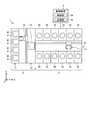
図1は、本実施形態に係る基板処理システムの概略構成を示す図である。以下では、位置関係を明確にするために、互いに直交するX軸、Y軸およびZ軸を規定し、Z軸正方向を鉛直上向き方向とする。 FIG. 1 is a diagram showing a schematic configuration of a substrate processing system according to the present embodiment. In the following, in order to clarify the positional relationship, the X-axis, Y-axis, and Z-axis that are orthogonal to each other are defined, and the positive direction of the Z-axis is defined as the vertically upward direction.
図1に示すように、基板処理システム1は、搬入出ステーション2と、処理ステーション3とを備える。搬入出ステーション2と処理ステーション3とは隣接して設けられる。 As shown in FIG. 1, the
搬入出ステーション2は、キャリア載置部11と、搬送部12とを備える。キャリア載置部11には、複数枚の基板、本実施形態では半導体ウェハ(以下ウェハW)を水平状態で収容する複数のキャリアCが載置される。 The loading /
搬送部12は、キャリア載置部11に隣接して設けられ、内部に基板搬送装置13と、受渡部14とを備える。基板搬送装置13は、ウェハWを保持するウェハ保持機構を備える。また、基板搬送装置13は、水平方向および鉛直方向への移動ならびに鉛直軸を中心とする旋回が可能であり、ウェハ保持機構を用いてキャリアCと受渡部14との間でウェハWの搬送を行う。 The
処理ステーション3は、搬送部12に隣接して設けられる。処理ステーション3は、搬送部15と、複数の処理ユニット16とを備える。複数の処理ユニット16は、搬送部15の両側に並べて設けられる。 The
搬送部15は、内部に基板搬送装置17を備える。基板搬送装置17は、ウェハWを保持するウェハ保持機構を備える。また、基板搬送装置17は、水平方向および鉛直方向への移動ならびに鉛直軸を中心とする旋回が可能であり、ウェハ保持機構を用いて受渡部14と処理ユニット16との間でウェハWの搬送を行う。 The
処理ユニット16は、基板搬送装置17によって搬送されるウェハWに対して所定の基板処理を行う。 The
また、基板処理システム1は、制御装置4を備える。制御装置4は、たとえばコンピュータであり、制御部18と記憶部19とを備える。記憶部19には、基板処理システム1において実行される各種の処理を制御するプログラムが格納される。制御部18は、記憶部19に記憶されたプログラムを読み出して実行することによって基板処理システム1の動作を制御する。 Further, the
なお、かかるプログラムは、コンピュータによって読み取り可能な記憶媒体に記録されていたものであって、その記憶媒体から制御装置4の記憶部19にインストールされたものであってもよい。コンピュータによって読み取り可能な記憶媒体としては、たとえばハードディスク(HD)、フレキシブルディスク(FD)、コンパクトディスク(CD)、マグネットオプティカルディスク(MO)、メモリカードなどがある。 The program may be recorded on a storage medium readable by a computer, and may be installed from the storage medium in the storage unit 19 of the control device 4. Examples of storage media that can be read by a computer include a hard disk (HD), a flexible disk (FD), a compact disk (CD), a magnet optical disk (MO), and a memory card.
上記のように構成された基板処理システム1では、まず、搬入出ステーション2の基板搬送装置13が、キャリア載置部11に載置されたキャリアCからウェハWを取り出し、取り出したウェハWを受渡部14に載置する。受渡部14に載置されたウェハWは、処理ステーション3の基板搬送装置17によって受渡部14から取り出されて、処理ユニット16へ搬入される。 In the
処理ユニット16へ搬入されたウェハWは、処理ユニット16によって処理された後、基板搬送装置17によって処理ユニット16から搬出されて、受渡部14に載置される。そして、受渡部14に載置された処理済のウェハWは、基板搬送装置13によってキャリア載置部11のキャリアCへ戻される。 The wafer W carried into the
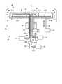
次に、処理ユニット16について図2を参照し説明する。図2は、処理ユニットの概略構成を示す図である。 Next, the
図2に示すように、処理ユニット16は、チャンバ20と、基板保持機構30と、処理流体供給部40と、回収カップ50とを備える。 As shown in FIG. 2, the
チャンバ20は、基板保持機構30と処理流体供給部40と回収カップ50とを収容する。チャンバ20の天井部には、FFU(Fan Filter Unit)21が設けられる。FFU21は、チャンバ20内にダウンフローを形成する。 The
基板保持機構30は、保持部31と、支柱部32と、駆動部33とを備える。保持部31は、ウェハWを水平に保持する。支柱部32は、鉛直方向に延在する部材であり、基端部が駆動部33によって回転可能に支持され、先端部において保持部31を水平に支持する。駆動部33は、支柱部32を鉛直軸まわりに回転させる。かかる基板保持機構30は、駆動部33を用いて支柱部32を回転させることによって支柱部32に支持された保持部31を回転させ、これにより、保持部31に保持されたウェハWを回転させる。 The
処理流体供給部40は、ウェハWに対して処理流体を供給する。処理流体供給部40は、処理流体供給源70に接続される。 The processing
回収カップ50は、保持部31を取り囲むように配置され、保持部31の回転によってウェハWから飛散する処理液を捕集する。回収カップ50の底部には、排液口51が形成されており、回収カップ50によって捕集された処理液は、かかる排液口51から処理ユニット16の外部へ排出される。また、回収カップ50の底部には、FFU21から供給される気体を処理ユニット16の外部へ排出する排気口52が形成される。 The
以下において、支柱部32の回転軸、すなわちウェハWの回転軸を、回転軸Ce(図3参照)として説明する。また、ウェハWの径方向を、径方向として説明することがある。 In the following, the rotation axis of the
ここで、処理ユニット16について、図3を参照し詳しく説明する。図3は、処理ユニット16の具体的な構成を示す図である。なお、図3では、処理流体供給部40など、一部の構成を省略している。 Here, the
保持部31は、保持プレート310と、基板保持部311と、リフトプレート312と、リフトピン313とを備える。 The holding
保持プレート310は、円板状に形成され、支柱部32の上端が挿入される孔が中心部に形成される。保持プレート310は、支柱部32の上端に接合される。保持プレート310は、支柱部32と同軸上に配置される。保持プレート310の外周端の上面には、複数の基板保持部311が設けられる。例えば、基板保持部311は、3か所設けられ、各基板保持部311は、周方向に120°の間隔で設けられる。基板保持部311は、リフトプレート312の上下動に合わせて保持プレート310側の基端部に設けた回動軸を中心に回動し、ウェハWの保持状態が切り替えられる。 The holding
また、保持プレート310には、昇降部材34が挿入可能な複数の挿入孔310aが形成される。例えば、挿入孔310aは、3か所設けられ、各挿入孔310aは、周方向に120度の間隔で設けられる。 Further, the holding
昇降部材34は、各挿入孔310aに応じて複数設けられる。昇降部材34は、昇降駆動部35によって昇降する。昇降部材34は、昇降駆動部35によって待機位置から上昇されると挿入孔310aに挿入され、挿入孔310aを貫通してリフトプレート312に当接する。そして、昇降部材34は、昇降駆動部35によってさらに上昇されると、リフトプレート312を上方に押し上げる。昇降部材34は、リフトプレート312を所定の上昇位置まで押し上げる。所定の上昇位置は、ウェハWを基板搬送装置17によって搬入および搬送する位置である。昇降部材34は、待機位置では、挿入孔310aに挿入されず、保持プレート310は、回転可能となる。 A plurality of elevating
なお、昇降部材34は、保持プレート310に設けられた中間部材を介してリフトプレート312を昇降させてもよい。 The lifting
リフトプレート312は、円板状に形成され、下面処理部80の軸部81が挿入される挿入孔が中心部に形成される。リフトプレート312は、保持プレート310、すなわち支柱部32と同軸上に配置される。リフトプレート312は、保持プレート310の上方に設けられ、昇降部材34が待機位置にある場合には、リフトプレート312の下面は保持プレート310の上面に当接する。リフトプレート312の外周端の上面には、複数のリフトピン313が設けられる。例えば、リフトピン313は、3か所設けられ、各リフトピン313は、周方向に120度の間隔で設けられる。リフトプレート312の径はウェハWの径よりも小さく、リフトプレート312は、昇降部材34によって押し上げられた場合に、基板保持部311に当接しないように形成される。 The
リフトピン313は、リフトプレート312が押し上げられると、ウェハWの下面に当接し、ウェハWが基板保持部311によって保持されない状態で、ウェハWを下面側から支持する。また、ウェハWを支持した状態でリフトプレート312が降下し、基板保持部311によってウェハWが保持された後に、さらにリフトプレート312が降下すると、リフトピン313は、ウェハWの下面から離間する。 When the
リフトプレート312の下面が保持プレート310の上面に当接する状態では、リフトプレート312と保持プレート310とは、例えば、係合部により係合する。そのため、駆動部33によって支柱部32が回転すると、リフトプレート312と保持プレート310とは支柱部32とともに回転する。 In a state where the lower surface of the
処理ユニット16は、ウェハWの下面に温調液などを供給する下面処理部80をさらに備える。下面処理部80は、軸部81と、ノズル82とを備える。軸部81およびノズル82は、耐薬品性を有する樹脂、例えば、PCTFE(ポリクロロトリフロオエチレン)樹脂によって構成される。なお、図3においては、説明のため下面処理部80のハッチングを省略している。 The
軸部81は、支柱部32と同軸上に配置される。軸部81は、中空状の支柱部32およびリフトプレート312の挿入孔に挿入され、ベアリング(不図示)を介して支柱部32、保持プレート310およびリフトプレート312を回転自在に支持する。 The
軸部81の内部には、第1流路81aと、第2流路81bと、第3流路81cとが形成される。各流路81a〜81cは、軸方向に延設される。なお、軸部81を中空状に形成し、各流路となる配管を、軸部81内に設けてもよい。 A
第1流路81aには、温調液供給源71によって温調液、例えば温度が調整された純水(温水)が第1配管90を介して供給される。なお、第1配管90には、開閉弁90aが設けられている。 A temperature-controlled liquid, for example, pure water (hot water) whose temperature has been adjusted by the temperature-controlled liquid supply source 71, is supplied to the
第2流路81bには、DIW供給源72によってDIW(常温の純水)が第2配管91を介して供給される。なお、第2配管91には、切替弁91aが設けられており、切替弁91aを切り替えて第2流路81bおよび第2配管91の一部とドレン流路91bとを連通することで、軸部81の上面に付着した薬液などを、液吐出流路820a(例えば、図4参照)、第2流路81bおよび第2配管91を介して排出可能となっている。すなわち、液吐出流路820a、第2流路81bおよび第2配管91の一部は排出路としても機能する。なお、切替弁91aとDIW供給源72との間の第2配管91には、開閉弁91cが設けられている。また、切替弁91aが開閉弁91cの機能を有してもよい。 DIW (pure water at room temperature) is supplied to the
第3流路81cには、N2供給源73によってN2ガスが第3配管92を介して供給される。N2ガスは、高温(例えば、90℃程度)に温調される。また、第3流路81cは、軸部81の上端に形成され、上方に延設されるN2ノズル81d内にも形成される。N2ノズル81dは、ノズル82の基部820(例えば、図4参照)に形成される挿入孔820b(例えば、図4参照)に挿入される。なお、第3配管92には、開閉弁92aが設けられている。 N2 gas is supplied to the
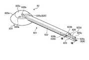
ここで、ノズル82について、図4〜図8を参照し詳しく説明する。図4は、ノズル82の平面図である。図5は、図4の矢視A図である。図6は、ノズル82の斜視図である。図7は、ノズル82の分解図である。図8は、図6のVIII−VIII断面図である。 Here, the
ノズル82は、基部820と、液供給部821とを備える。ノズル82は、リフトプレート312(図3参照)とウェハW(図3参照)との間に設けられ、ウェハWの下面と向き合うように設けられる。すなわち、ノズル82は、ウェハWよりも下方に設けられる。また、ノズル82は、ウェハWの下面とわずかに離間するように設けられる。 The
基部820は、軸部81と同軸上に配置される。すなわち、基部820は、ウェハWの回転軸Ceを含むように設けられる。基部820は、軸部81の上端に取り付けられる。基部820には、第2流路81bと連通する液吐出流路820aと、N2ノズル81dが挿入される挿入孔820bとが形成される。液吐出流路820aおよび挿入孔820bは、軸方向に沿って形成される。また、基部820には、第1流路81a(図3参照)に連通し、かつ液供給部821のノズル基部822に形成される第1液供給路822aに連通する中間流路(不図示)が内部に形成される。中間流路は、軸方向に沿って形成される。 The
基部820は、ベアリング(不図示)を介してリフトプレート312(図3参照)に着座しており、リフトプレート312を回転自在に支持すると共に、リフトプレート312の昇降に伴い昇降する。すなわち、ノズル82(下面処理部80)は、リフトプレート312とともに昇降する。 The
基部820の上端中央部には、下方に向けて窪んだ凹部820cが形成される。凹部820cには、液吐出流路820aおよび挿入孔820bが開口する。凹部820cは、凹部820cに付着した液が液吐出流路820aに流入するように形成される。すなわち、凹部820cは、液吐出流路820aに液が流入するように、すり鉢状に形成され、例えば、凹部820cを形成する面が液吐出流路820aの中心に向けて収束するように形成される。 A
液吐出流路820aおよび挿入孔820bは、回転軸Ce付近に形成される。すなわち、挿入孔820bおよび挿入孔820bに挿入されるN2ノズル81dは、回転軸Ceから径方向外側にオフセットした位置に設けられる。N2ノズル81dから吐出されるN2ガスが、ウェハWの中心に供給されると、N2ノズル81dの径より小さい液滴がウェハWに残るおそれがある。これを抑制するために、N2ノズル81dは、回転軸Ceから径方向外側にオフセットした位置に設けられる。 The liquid
また、基部820の上端外周部には、凹部820cの周縁から外周側下方に向けて傾斜する傾斜部820eが形成される。すなわち、傾斜部820eは、径方向外側となるにつれて下方に傾斜する。傾斜部820eは、基部820の中心側から傾斜するように形成されることが望ましい。すなわち、凹部820cの周縁がより径方向内側に位置するように、凹部820cおよび傾斜部820eが形成されることが望ましい。 Further, an
傾斜部820eは、図9に示すように、基部820の下面820fに接続される。すなわち、傾斜部820eは、凹部820cの周縁から基部820の下面まで延設して形成される。図9は、図3における下面処理部80の一部を拡大した模式図である。 The
軸部81と、軸部81が挿入される支柱部32の挿入孔の内周面との間には、第1隙間320が形成される。また、基部820の下面820fとリフトプレート312との間には、第1隙間320と連通する第2隙間321が形成される。このような隙間320、321は、回転しない軸部81およびノズル82と、回転する支柱部32およびリフトプレート312との間に生じる。 A
ウェハW、支柱部32およびリフトプレート312が回転すると、第1隙間320および第2隙間321で負圧を発生することがあり、ウェハWの中心側が下側に撓むことがある。これを防ぐために、第1隙間320および第2隙間321には、気体、例えば、N2供給源73からN2ガスが供給される。これにより、負圧が発生することを防止し、ウェハWが下側に撓んだ状態で回転することを抑制することができ、ウェハWとノズル82などの接触を抑制することができる。 When the wafer W, the
しかし、第1隙間320および第2隙間321から吐出されたN2ガスがウェハWの下面に当たると、ウェハWの温度が低くなり、処理の進行が遅くなったり、ウェハWにおける処理が不均一になったりするおそれがある。 However, when the N2 gas discharged from the
本実施形態では、傾斜部820eを基部820の下面820fまで延設することで、基部820の下面820fを径方向外側まで延設することができ、N2ガスがウェハWに向けて吐出されることを抑制することができる。これにより、処理の進行が遅くなったり、ウェハWにおける処理が不均一になったりすることを抑制することができる。 In the present embodiment, by extending the
また、傾斜部820eは、基部820の強度を確保しつつ、回転軸Ceとのなす角がより鋭角となることが望ましい。例えば、傾斜部820eは回転軸Ceとのなす角が45度から50度程度となるように設けられる。 Further, it is desirable that the
このように、傾斜部820eを設けることで、基部820の上面に付着した液を基部820の外側へ流すことができる。 By providing the
なお、基部820の上端の高さが、後述するノズル基部822の上端の高さよりも低くなるように基部820は形成される。これにより、基部820側のノズル基部822に付着した液を基部820の凹部820cや傾斜部820eに流すことができる。 The
液供給部821は、棒状に形成され、基部820の中心付近から径方向外側に延設される。液供給部821は、ノズル基部822と、ノズルキャップ823とを備える。 The
径方向内側のノズル基部822の端部は、凹部820c内に突出するように形成される。なお、径方向内側のノズル基部822の先端は、回転軸Ceよりも径方向外側に位置する。 The end of the
ノズル基部822の内部には、第1液供給路822aと、圧入孔822bとが径方向に沿って形成される。第1液供給路822aと圧入孔822bとは平行に形成される。径方向内側の圧入孔822bの端部は、閉塞されている。圧入孔822bには、補強部材824が圧入される。 Inside the
補強部材824は、中空状の空洞部を有する金属部材であり、例えば、ステンレス鋼である。なお、補強部材824は、ステンレス鋼に限定されず、液供給部821の撓みを抑制する部材であればよい。補強部材824を中空状にすることで、補強部材824を圧入孔822bに圧入する際に、空洞部を介して圧入孔822b内の空気が外部に排出されるので、補強部材824を圧入孔822bへ容易に圧入することができる。また、中空状にすることで、ノズル82の保温効果を向上させることができ、第1液供給路822aを流れる温調液の温度が低下することを抑制することができる。 The reinforcing
径方向外側の圧入孔822bの端部には、シール材825が挿入される。また、径方向外側の圧入孔822bにはネジ溝が形成されており、ネジ826によってノズルキャップ823が取り付けられる。ネジ826は、ノズル82と同様に耐薬品性の樹脂によって構成される。 A sealing
ノズルキャップ823は、径方向外側のノズル基部822の先端に取り付けられる。ノズルキャップ823には、第1液供給路822aと連通する第2液供給路823aが形成される供給部823dと、ネジ826が挿入されるネジ孔が形成されるネジ取付部823bとを備える。ノズルキャップ823は、ネジ826によってノズル基部822に取り付けられる。 The
供給部823dは、第2液供給路823aが、ノズルキャップ823の先端側、すなわち径方向外側で閉塞されるように形成される。このように、第1液供給路822aと第2液供給路823aとによって液供給路が形成される。また、供給部823dの先端側の上部には、下方に傾斜するテーパ部823cが形成される。 The
ネジ取付部823bは、ウェハWの回転時に、ネジ826がリフトピン313(図3参照)に当接しないように、供給部823dの先端よりも径方向内側に設けられる。すなわち、ノズルキャップ823は、平面視において略L字状に形成される。 The
ノズル基部822およびノズルキャップ823には、上方の突出する段部827が形成される。段部827は、例えば、平面視において、頂部から径方向とは交差する方向に傾斜する傾斜面によって形成される。段部827には、液供給路に連通し、ウェハWの下面に向けて温調液を吐出する吐出口828が複数形成される。吐出口828を段部827に形成することで、例えば、液吐出流路820aから吐出された液が吐出口828内に流入することを抑制することができる。 An upward protruding
吐出口828は、基部820の中心側からノズルキャップ823の先端側、すなわちノズルキャップ823のテーパ部823cまで所定の間隔を設けて形成される。また、吐出口828は、吐出口828の合計面積が、第1流路81aの断面積や、最も径方向内側の第1液供給路822aの断面積よりも小さくなるように形成される。これにより、各吐出口828から吐出される温調液の流量を均一にすることができる。 The
吐出口828は、基部820の中心側、すなわち回転軸Ce付近に形成された第1吐出口828aと、第1吐出口828aよりも径方向外側に形成される第2吐出口828bと、テーパ部823cに形成される第3吐出口828cとにより構成される。 The
第1吐出口828aは、凹部820c内に突出するノズル基部822に形成される。第1吐出口828aは、上下方向(鉛直方向)において、第1液供給路822aと重なるように形成される。また、第1吐出口828aは、軸方向に沿って温調液を吐出するように形成される。これにより、ウェハWの中心付近の下面に温調液を吐出することができる。 The
なお、最も回転軸Ce側の第1吐出口828aは、回転軸Ceよりも径方向外側に形成される。最も回転軸Ce側の第1吐出口828aを回転軸Ceよりも径方向外側に形成することで、遠心力が働かないウェハWの中心部が、第1吐出口828aから吐出された温調液により温度が高くなることを抑制し、ウェハWの中心部の処理が他の領域よりも進行することを抑制し、エッチング処理を均一に行うことができる。 The
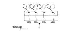
第2吐出口828bは、図10に示すように、上下方向において、第1液供給路822aおよび第2液供給路823aと重ならないように、第1液供給路822aおよび第2液供給路823aに対してウェハWの回転方向の下流側にオフセットして形成される。第2吐出口828bは、ウェハWの回転方向においてノズル82よりも後方側の斜め上方に向けて温調液を吐出する。図10は、第2吐出口828bから吐出される温調液の吐出方向を側面視で示す概略図である。これにより、ウェハWに当たった温調液がノズル82に向けて落ちることを抑制し、ノズル82に温調液が付着することを抑制することができる。 As shown in FIG. 10, the
また、第2吐出口828bは、図11に示すように、平面視においてノズル82に対して垂直な方向(図11中、破線矢印)よりも外側(図11中、実線矢印)に向けて温調液を吐出するように形成される。すなわち、第2吐出口828bは、温調液を外側斜め上方に向けて吐出するように形成される。図11は、第2吐出口828bから吐出される温調液の吐出方向およびウェハWの下面における温調液の吐出範囲を示す概略図である。温調液を外側斜め上方に向けて吐出することで、ノズル82に対して垂直な方向に向けて吐出する場合(図11中、破線範囲)よりも吐出距離が長くなるため、ウェハWの下面の広範囲(図11中、実線範囲)に温調液を吐出することができる。なお、図4〜図7では、一部の第2吐出口828bを省略している。 Further, as shown in FIG. 11, the
第3吐出口828cは、基本的な構成は、第2吐出口828bと同じであり、第2吐出口828bよりも温調液を径方向外側に向けて吐出するように形成される。これにより、液供給部821を延ばすことができないウェハWの外周端側の下面に温調液を吐出することができる。例えば、リフトピン313の上方に位置するウェハWの下面や、リフトピン313よりも径方向外側に位置するウェハWの下面に温調液を吐出することができる。これにより、ウェハWの外周端側の温度が低下することを抑制することができる。 The
なお、第3吐出口828cは、温調液を、ウェハWの回転方向においてノズル82よりも後方側に吐出せずに、径方向外側の斜め上方に向けて吐出するように形成されてもよい。 The
ノズルキャップ823の先端側の第2吐出口828bの間隔、および第3吐出口828cの間隔は、基部820側の第2吐出口828bの間隔よりも短い。例えば、基部820側の第2吐出口828bの間隔は、10mmであり、第3吐出口828cおよびテーパ部823c近傍の第2吐出口828bの間隔は、8mmである。 The distance between the
このように、ノズルキャップ823の先端側に設けた第2吐出口828bおよび第3吐出口828cの間隔を短くすることで、ウェハWの周縁側の下面に吐出される面積当たりの供給量を多くすることができる。 By shortening the distance between the
また、第2吐出口828bは、径方向外側となるにつれて第2吐出口828bの間隔が小さくなるように形成してもよい。 Further, the
なお、図4〜図7では、第1吐出口828aおよび第3吐出口828cを2つ形成した一例を示しているが、これに限られることはなく、1つ以上であればよい。 Although FIGS. 4 to 7 show an example in which two
ノズル82の外周端、すなわちノズルキャップ823の外周端は、リフトピン313よりも径方向内側に位置する。そのため、リフトプレート312が保持プレート310と共に回転した場合であっても、ノズル82とリフトピン313とが接触することはない。 The outer peripheral end of the
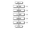
次に、本実施形態に係る基板処理システム1が実行する基板処理の内容について図12を参照して説明する。図12は、本実施形態に係る基板処理システム1が実行する処理の処理手順を示すフローチャートである。なお、図12に示す各処理手順は、制御装置4の制御部18の制御に従って実行される。 Next, the contents of the substrate processing executed by the
基板搬送装置17によって処理ユニット16にウェハWを搬入する搬入処理が行われる(S1)。搬入処理では、所定の上昇位置までリフトプレート312が押し上げられ、基板搬送装置17によってリフトピン313上にウェハWが載置される。そして、リフトピン313上に載置された後に、リフトプレート312が降下し、基板保持部311によってウェハWが保持される。この状態では、ノズル82およびリフトピン313と、ウェハWの下面とはわずかに離間している。 The
処理ユニット16では、薬液処理が行われる(S2)。薬液処理では、駆動部33によって保持部31が回転され、ウェハWが回転する。そして、処理流体供給部40のエッチング液供給用ノズル(不図示)からエッチング液、例えば、SC1や、DHFや、SPMがウェハWの上面に供給され、また、下面処理部80のノズル82から温調液がウェハWの下面に供給される。これにより、ウェハWの上面にエッチング処理が行われる。 In the
その際、吐出口828からウェハWの下面に温調液が供給されることで、ウェハWの温度を均一にすることができ、ウェハWに対し、エッチング処理を均一に行うことができる。 At that time, by supplying the temperature control liquid from the
また、エッチング液供給用ノズルは、ウェハWの中心から外周端まで往復動しながらエッチング液をウェハWの上面に供給する。なお、ウェハWの外周端にエッチング液を供給するノズル82を別に設けてもよい。これにより、ウェハWに対し、エッチング処理を均一に行うことができる。 Further, the etching solution supply nozzle reciprocates from the center of the wafer W to the outer peripheral edge to supply the etching solution to the upper surface of the wafer W. A
処理ユニット16では、薬液処理後にリンス処理が行われる(S3)。リンス処理では、処理流体供給部40のリンス液供給用ノズル(不図示)からDIWがウェハWの上面に供給される。また、下面処理部80の液吐出流路820aからDIWがウェハWの下面に供給される。これにより、ウェハWに残存するエッチング液がDIWによって洗い流される。 In the
続いて、処理ユニット16では、乾燥処理が行われる(S4)。乾燥処理では、処理流体供給部40の乾燥液供給用ノズル(不図示)からIPAがウェハWの上面に供給される。また、下面処理部80のN2ノズル81dからN2ガスがウェハWの下面に供給される。N2ガスがウェハWの下面に供給されることで、乾燥処理が促進される。 Subsequently, in the
ウェハWが回転している場合に、ウェハWの中心部は、ウェハWの周縁部よりも遠心力が小さい。そのため、ウェハWの中心部の下に位置する基部820の上端中央部には液が落下し易く、液が付着し易い。 When the wafer W is rotating, the central portion of the wafer W has a smaller centrifugal force than the peripheral portion of the wafer W. Therefore, the liquid is likely to fall and adhere to the central portion of the upper end of the
上記実施形態では、基部820の上端中央部に付着した液が液吐出流路820aに流入するように凹部820cが形成されている。そのため、凹部820cに残存する液が少なく、乾燥処理時に、凹部820cに残存した液がウェハWの下面に付着することを抑止することができる。 In the above embodiment, the
また、乾燥処理では、切替弁91aが切り替えられ、液吐出流路820a、第2流路81bおよび第2配管91の一部と、ドレン流路91bとが連通する。これにより、液吐出流路820aに流入した液がドレン流路91bを介して排出されるので、ウェハWの下面に液が付着することを抑制することができる。また、液吐出流路820aとドレン流路91bとが連通することで液吐出流路820aの開口付近が負圧となるため、凹部820cに残存した液が液吐出流路820aに吸引され排出される。これにより、凹部820cに残存した液がウェハWの下面に付着することをさらに抑制することができる。 Further, in the drying process, the switching
なお、リンス処理および乾燥処理では、ウェハWは基板保持部311により保持され、回転している。 In the rinsing process and the drying process, the wafer W is held and rotated by the
次に、処理ユニット16では、搬出処理が行われる(S5)。搬出処理では、ウェハWの回転が停止された後に、昇降部材34によりリフトプレート312が所定の上昇位置まで押し上げられる。そして、基板搬送装置17によってウェハWが処理ユニット16から搬出される。 Next, the
次に本実施形態の効果について説明する。 Next, the effect of this embodiment will be described.
基部820の上面に開口する液吐出流路820aを排出路として機能させ、基部820の上端中央部に液吐出流路820aに向けて液が流れるように下方に窪んだ凹部820cを形成することで、凹部820cに残存した液を液吐出流路820aに流すことができる。 The liquid
これにより、凹部820cに液が残ることを抑制し、凹部820cに残存した液がウェハWの下面に付着することを抑制することができる。 As a result, it is possible to prevent the liquid remaining in the
凹部820cの周縁から基部820の外側となるにつれて下方に傾斜する傾斜部820eを設け、基部820の上面に付着した液を基部820の外側に排出することで、基部820の上面に残存する液を少なくし、液がウェハWの下面に付着することを抑制することができる。 An
また、凹部820cの周縁から傾斜部820eを設けることで、水平な面が基部820の上面に形成されない。そのため、基部820の上面に残存する液を少なくし、液がウェハWの下面に付着することを抑制することができる。 Further, by providing the
軸部81と支柱部32との間に形成される第1隙間320と、リフトプレート312と基部820の下面820fとの間に形成される第2隙間321とにN2ガスなどを供給し、傾斜部820eを基部820の下面820fまで延設する。 N2 gas or the like is supplied to the
これにより、ウェハWを回転させる場合に、第1隙間320および第2隙間321で負圧が発生することを防止し、ウェハWが撓んだ状態で回転することを抑制することで、ウェハWとノズル82などの接触を抑制することができる。また、第2隙間321から吐出されたN2ガスがウェハWに向けて吐出されることを抑制することができ、ウェハWが冷却されることを抑制することができる。そのため、処理の進行が遅くなったり、ウェハWにおける処理が不均一になったりすることを抑制することができる。 As a result, when the wafer W is rotated, negative pressure is prevented from being generated in the
上下方向において第1液供給路822aと重なるように第1吐出口828aが形成される。また、第1吐出口828aよりも径方向外側であり、上下方向において第1液供給路822aおよび第2液供給路823aと重ならないように、第1液供給路822aおよび第2液供給路823aに対してウェハWの回転方向の下流側にオフセットされた第2吐出口828bが形成される。 The
これにより第1吐出口828aによってウェハWの中心側の下面に温調液を吐出することができる。また、第2吐出口828bから吐出された温調液がノズル82に付着することを抑制することができる。 As a result, the temperature control liquid can be discharged to the lower surface on the center side of the wafer W by the
ノズル82に上方の突出する段部827を設け、段部827に吐出口828が形成される。これにより、ノズル82の上面に液が残ることを抑制することができる。 The
また、基部820の上端の高さを、ノズル基部822の上端の高さよりも低くする。これにより、基部820側のノズル基部822に付着した液を基部820の凹部820cや傾斜部820eに流すことができる。 Further, the height of the upper end of the
液供給部821の先端側の上部にテーパ部823cを設け、テーパ部823cに第3吐出口828cが形成される。これにより、テーパ部823cが形成されない場合と比較して、よりウェハWの外周側へ温調液を届かせることができ、液供給部821の先端側に温調液が残りにくい。さらに、第3吐出口828cの加工が容易になる。 A tapered
また、第3吐出口828cは、径方向外側に向けて温調液を吐出するように形成される。これにより、ウェハWの外周端の下方にリフトピン313が設けられている場合でも、ウェハWの外周端の下面に温調液を吐出することができ、ウェハWの外周側の温度が低くなることを抑制し、ウェハWに対し、エッチング処理を均一に行うことができる。 Further, the
径方向内側のノズル基部822の端部は、凹部820c内に突出するように形成され、凹部820c内に突出するノズル基部822に第1吐出口828aが形成される。これにより、第1吐出口828aから吐出され、ウェハWに当たって落ちた温調液を凹部820cを介して液吐出流路820aに流すことができる。 The end portion of the
また、最も回転軸Ce側の第1吐出口828aは、回転軸Ceよりも径方向外側に形成される。これにより、回転軸Ceの下面に温調液が吐出されることを抑制し、遠心力が働かないウェハWの中心部の処理が他の領域よりも進行することを抑制し、ウェハWに対し、エッチング処理を均一に行うことができる。 Further, the
吐出口828は、吐出口828の合計面積が、第1流路81aや、最も径方向内側の第1液供給路822aの断面積よりも小さくなるように形成される。これにより、各吐出口828から吐出される温調液の流量を均一にすることができる。 The
液供給部821は、ノズル基部822と、径方向外側のノズル基部822の先端に取り付けられるノズルキャップ823とによって構成される。これにより、簡易な構成で液供給部821を形成することができる。 The
ノズルキャップ823は、第2液供給路823aが形成される供給部823dと、供給部823dの先端よりも径方向内側に形成され、ネジ826によってノズルキャップ823をノズル基部822に取り付けるネジ取付部823bとを備える。これにより、ウェハWが回転した場合に、ネジ826がリフトピン313に接触することを防止することができる。 The
第1液供給路822aに対して平行に補強部材824を設けることで、液供給部821が撓むことを抑制し、液供給部821と他の部材、例えば、ウェハWやリフトプレート312に接触することを防止することができる。 By providing the reinforcing
補強部材824に中空状の空洞部を設けることで、ノズル82の保温効果を向上させることができ、温調液の温度が低くなることを抑制することができる。 By providing the reinforcing
次に本実施形態の変形例について説明する。 Next, a modified example of this embodiment will be described.
上記実施形態では、ノズル82から温調液である純水を吐出したが、エッチング液を吐出してもよい。また、液吐出流路820aからウェハWの下面にDIWを供給したが、SC1などの薬液を供給してもよい。 In the above embodiment, pure water, which is a temperature control liquid, is discharged from the
また、上記実施形態では、薬液処理を1回行う場合について説明したが、薬液処理を複数回行ってもよい。また、切替弁91aを切り替えて液吐出流路820aとドレン流路91bとが連通するタイミングは、乾燥処理時に限られず、他の処理時に、または各処理間であってもよい。これにより、ウェハWの下面に液が付着することを抑制することができる。 Further, in the above embodiment, the case where the chemical solution treatment is performed once has been described, but the chemical solution treatment may be performed a plurality of times. Further, the timing at which the switching
また、上記実施形態では、補強部材824は空洞部を有しているが、空洞部を有しない、例えば円柱状としてもよい。また、補強部材824を圧入孔822bに圧入したが、ノズル基部822に設けた孔に、例えば、円柱状の補強部材824を挿入してもよい。なお、孔に挿入する場合には補強部材824と孔との隙間が小さくなるように補強部材824および孔が調整される。このような構成によっても、液供給部821の撓みを抑制することができる。 Further, in the above embodiment, the reinforcing
また、凹部820cに付着した液を排出する排出口、排出路を、基部820や軸部81などに別途設けてもよい。 Further, a discharge port and a discharge path for discharging the liquid adhering to the
また、ノズル82の表面を疎水性にしてもよい。これにより、凹部820cや傾斜部820eや、段部827に液が残ることを抑制することができる。 Further, the surface of the
さらなる効果や変形例は、当業者によって容易に導き出すことができる。このため、本発明のより広範な態様は、以上のように表しかつ記述した特定の詳細および代表的な実施形態に限定されるものではない。したがって、添付の特許請求の範囲およびその均等物によって定義される総括的な発明の概念の精神または範囲から逸脱することなく、様々な変更が可能である。 Further effects and variations can be easily derived by those skilled in the art. For this reason, the broader aspects of the invention are not limited to the particular details and representative embodiments expressed and described as described above. Therefore, various modifications can be made without departing from the spirit or scope of the general concept of the invention as defined by the appended claims and their equivalents.
1 基板処理システム(液処理装置)
16 処理ユニット
18 制御部
30 基板保持機構
31 保持部
32 支柱部
33 駆動部
73 N2供給源(気体供給部)
80 下面処理部
81 軸部
81b 第2流路(排出路)
82 ノズル
91 第2配管(排出路)
310 保持プレート
311 基板保持部
312 リフトプレート(板部)
313 リフトピン
820 基部
820a 液吐出流路(排出路)
820c 凹部
820e 傾斜部
821 液供給部
822 ノズル基部(第1供給部)
822a 第1液供給路(液供給流路)
822b 圧入孔
823 ノズルキャップ(第2供給部)
823a 第2液供給路(液供給流路)
823b ネジ取付部(取付部)
823c テーパ部
823d 供給部
824 補強部材
826 ネジ(固定部)
828 吐出口
828a 第1吐出口
828b 第2吐出口
828c 第3吐出口1 Substrate processing system (liquid processing equipment)
16
80 Bottom
82
310
313
820c
822a First liquid supply path (liquid supply channel)
822b Press-
823a Second liquid supply path (liquid supply channel)
823b Screw mounting part (mounting part)
823c
828
Claims (11)
Translated fromJapanese前記基板保持部を回転させる駆動部と、
前記基板保持部に保持された前記基板の回転軸を含み、前記回転軸の軸方向に沿って延設され、かつ前記基板よりも下方に設けられた軸部と、
前記軸部の上端に取り付けられる基部と、前記基部から前記基板の径方向外側に延設され、前記基板に向けて液を吐出する吐出口が形成された液供給部とを有し、前記基板の下面に向けて液を吐出するノズルと、
挿入孔に挿入された前記軸部によって回転自在に支持されて前記基板保持部とともに回転する支柱部と、
前記基部の下面および前記基板の下面と向かい合い、前記基板保持部と一体に回転する板部と、
前記挿入孔を形成する内周面と前記軸部との間に形成される第1間隙を介して、前記基部の下面と前記板部との間に形成され、前記第1間隙に連通する第2間隙に気体を供給する気体供給部と
を備え、
前記軸部および前記基部は、
前記軸方向に沿って形成され、前記基板の下面に向けて吐出された前記液を排出する排出路を備え、
前記基部は、
前記液が前記排出路に向けて流れるように下方に向けて窪んだ凹部と、
前記凹部の周縁から前記基部の外側となるにつれて下方に傾斜する傾斜部と、
を備え、
前記傾斜部は、
前記基部の下面まで延設される
液処理装置。A board holding part that holds the board horizontally,
A drive unit that rotates the substrate holding unit and
A shaft portion including a rotating shaft of the substrate held by the substrate holding portion, extending along the axial direction of the rotating shaft, and provided below the substrate.
The substrate has a base portion attached to the upper end of the shaft portion and a liquid supply portion extending radially outward from the base portion and forming a discharge port for discharging liquid toward the substrate. A nozzle that discharges liquid toward the bottom surface of the
A strut portion that is rotatably supported by the shaft portion inserted into the insertion hole and rotates together with the substrate holding portion.
A plate portion that faces the lower surface of the base portion and the lower surface of the substrate and rotates integrally with the substrate holding portion.
A first gap formed between the lower surface of the base portion and the plate portion via a first gap formed between the inner peripheral surface forming the insertion hole and the shaft portion, and communicating with the first gap. It is equipped witha gas supply unit that supplies gas to the two gaps.
Before Kijiku portion and said base portion,
A discharge path formed along the axial direction and discharging the liquid discharged toward the lower surface of the substrate is provided.
The base is
A recess that is recessed downward so that the liquid flows toward the discharge path,
An inclined portion that inclines downward from the peripheral edge of the concave portion toward the outside of the base portion,
With
The inclined portion is
A liquid treatment deviceextending to the lower surface of the base .
前記基板保持部を回転させる駆動部と、
前記基板保持部に保持された前記基板の回転軸を含み、前記回転軸の軸方向に沿って延設され、かつ前記基板よりも下方に設けられた軸部と、
前記基板の下面に向けて液を吐出するノズルと、
を備え、
前記ノズルは、
前記軸部の上端に取り付けられる基部と、前記基部から前記基板の径方向外側に延設され、前記基板に向けて液を吐出する吐出口が形成された液供給部とを備え、
前記軸部および前記基部は、
前記軸方向に沿って形成され、前記基板の下面に向けて吐出された前記液を排出する排出路を備え、
前記基部は、
前記液が前記排出路に向けて流れるように下方に向けて窪んだ凹部を備え、
前記液供給部は、
前記基板の径方向に沿って形成され、前記吐出口と連通する液供給流路を備え、
前記吐出口は、
前記基部側に形成され、上下方向において前記液供給流路と重なるように形成された1個以上の第1吐出口と、
前記第1吐出口よりも前記径方向外側に複数形成され、前記上下方向において前記液供給流路と重ならないように、前記液供給流路に対して前記基板の回転方向の下流側にオフセットして形成される1個以上の第2吐出口と
を含み、
前記回転軸側の前記液供給部は、
前記凹部内に突出し、
前記第1吐出口は、
前記凹部内の前記液供給部に形成される
液処理装置。A board holding part that holds the board horizontally,
A drive unit that rotates the substrate holding unit and
A shaft portion including a rotating shaft of the substrate held by the substrate holding portion, extending along the axial direction of the rotating shaft, and provided below the substrate.
A nozzle that discharges liquid toward the lower surface of the substrate,
With
The nozzle
A base portion attached to the upper end of the shaft portion and a liquid supply portion extending from the base portion to the outside in the radial direction of the substrate and having a discharge port for discharging liquid toward the substrate are provided.
The shaft portion and the base portion
A discharge path formed along the axial direction and discharging the liquid discharged toward the lower surface of the substrate is provided.
The base is
It is provided with a recess that is recessed downward so that the liquid flows toward the discharge path.
The liquid supply unit
A liquid supply flow path formed along the radial direction of the substrate and communicating with the discharge port is provided.
The discharge port is
One or more first discharge ports formed on the base side and overlapped with the liquid supply flow path in the vertical direction.
A plurality of them are formed on the outer side in the radial direction from the first discharge port, and are offset to the downstream side in the rotational direction of the substrate with respect to the liquid supply flow path so as not to overlap the liquid supply flow path in the vertical direction. With one or more second outlets formed by
Including
The liquid supply unit on the rotating shaft side is
Protruding into the recess
The first discharge port is
Formed in the liquid supply portion in the recess
Liquid treatment equipment.
前記回転軸よりも前記径方向外側に形成される
請求項2に記載の液処理装置。The first discharge port closest to the rotation axis is
The liquid treatment apparatus according to claim2 , which is formed outside the rotation axis in the radial direction.
前記液供給部の先端側の上部に形成されたテーパ部
をさらに備え、
前記吐出口は、
前記テーパ部に形成された1個以上の第3吐出口を含む、
請求項2または3に記載の液処理装置。The liquid supply unit
Further provided with a tapered portion formed on the upper end side of the liquid supply portion,
The discharge port is
Includes one or more third outlets formed in the tapered portion.
The liquid treatment apparatus according to claim2 or 3 .
前記径方向外側に向けて前記液を吐出するように形成される
請求項4に記載の液処理装置。The third discharge port is
The liquid treatment apparatus according to claim4 , which is formed so as to discharge the liquid toward the outside in the radial direction.
前記基部から前記径方向に沿って延設される第1液供給部と、
前記径方向外側の前記第1液供給部の端部に取り付けられ、前記径方向に沿って延設される第2液供給部とを備える
請求項2〜5のいずれか一つに記載の液処理装置。The liquid supply unit
A first liquid supply unit extending from the base portion along the radial direction,
The liquid according to any one of claims2 to 5 , further comprising a second liquid supply unit attached to the end portion of the first liquid supply unit on the outer side in the radial direction and extending along the radial direction. Processing equipment.
前記液供給流路および前記吐出口が形成される供給部と、
前記径方向外側の前記供給部の先端よりも前記軸部側に設けられ、固定部によって前記第1液供給部に取り付けられる取付部と
を備える
請求項6に記載の液処理装置。The second liquid supply unit is
A supply unit in which the liquid supply flow path and the discharge port are formed,
The liquid treatment apparatus according to claim6 , further comprising a mounting portion provided on the shaft portion side of the tip of the supply portion on the outer side in the radial direction and attached to the first liquid supply portion by a fixing portion.
前記液供給流路に対して平行に形成された孔と、
前記孔に挿入される補強部材と
を備える
請求項6または7に記載の液処理装置。The first liquid supply unit is
A hole formed parallel to the liquid supply flow path and
The liquid treatment apparatus according to claim6 or 7 , further comprising a reinforcing member inserted into the hole.
中空状である
請求項8に記載の液処理装置。The reinforcing member is
The liquid treatment apparatus according to claim8 , which is hollow.
前記液供給部に前記液を供給する流路の断面積よりも小さい
請求項1〜9のいずれか一つに記載の液処理装置。The total area of the discharge port is
The liquid treatment apparatus according to any one of claims 1 to9 , which is smaller than the cross-sectional area of the flow path for supplying the liquid to the liquid supply unit.
前記基部の上端の高さが、前記液供給部の上端の高さよりも低くなるように形成される
請求項1〜10のいずれか一つに記載の液処理装置。
The nozzle
The liquid treatment apparatus according to any one of claims 1 to10 , wherein the height of the upper end of the base portion is formed to be lower than the height of the upper end of the liquid supply portion.
Priority Applications (5)
| Application Number | Priority Date | Filing Date | Title |
|---|---|---|---|
| JP2017022350AJP6804325B2 (en) | 2017-02-09 | 2017-02-09 | Liquid treatment equipment |
| US15/881,984US11322373B2 (en) | 2017-02-09 | 2018-01-29 | Liquid processing apparatus |
| TW107103140ATWI748047B (en) | 2017-02-09 | 2018-01-30 | Liquid treatment device |
| KR1020180012647AKR102468100B1 (en) | 2017-02-09 | 2018-02-01 | Liquid processing apparatus |
| CN201810132808.3ACN108417510B (en) | 2017-02-09 | 2018-02-09 | Liquid treatment device |
Applications Claiming Priority (1)
| Application Number | Priority Date | Filing Date | Title |
|---|---|---|---|
| JP2017022350AJP6804325B2 (en) | 2017-02-09 | 2017-02-09 | Liquid treatment equipment |
Publications (2)
| Publication Number | Publication Date |
|---|---|
| JP2018129438A JP2018129438A (en) | 2018-08-16 |
| JP6804325B2true JP6804325B2 (en) | 2020-12-23 |
Family
ID=63037373
Family Applications (1)
| Application Number | Title | Priority Date | Filing Date |
|---|---|---|---|
| JP2017022350AActiveJP6804325B2 (en) | 2017-02-09 | 2017-02-09 | Liquid treatment equipment |
Country Status (5)
| Country | Link |
|---|---|
| US (1) | US11322373B2 (en) |
| JP (1) | JP6804325B2 (en) |
| KR (1) | KR102468100B1 (en) |
| CN (1) | CN108417510B (en) |
| TW (1) | TWI748047B (en) |
Families Citing this family (6)
| Publication number | Priority date | Publication date | Assignee | Title |
|---|---|---|---|---|
| JP7096112B2 (en)* | 2018-09-13 | 2022-07-05 | キオクシア株式会社 | Semiconductor manufacturing equipment and methods for manufacturing semiconductor equipment |
| JP7190912B2 (en)* | 2019-01-10 | 2022-12-16 | 東京エレクトロン株式会社 | Substrate processing equipment |
| JP7253955B2 (en)* | 2019-03-28 | 2023-04-07 | 東京エレクトロン株式会社 | SUBSTRATE PROCESSING APPARATUS AND SUBSTRATE PROCESSING METHOD |
| JP7241868B2 (en)* | 2019-06-04 | 2023-03-17 | 東京エレクトロン株式会社 | SUBSTRATE PROCESSING APPARATUS AND SUBSTRATE PROCESSING METHOD |
| JP7370201B2 (en)* | 2019-09-20 | 2023-10-27 | 株式会社Screenホールディングス | Substrate processing equipment |
| CN113903701A (en)* | 2020-07-06 | 2022-01-07 | 弘塑科技股份有限公司 | Wet processing equipment for porous substrates |
Family Cites Families (14)
| Publication number | Priority date | Publication date | Assignee | Title |
|---|---|---|---|---|
| KR100887360B1 (en)* | 2001-01-23 | 2009-03-06 | 도쿄엘렉트론가부시키가이샤 | Substrate processing apparatus and substrate processing method |
| US20040162007A1 (en)* | 2003-02-19 | 2004-08-19 | Ky Phan | Chemical mechanical polishing atomizing rinse system |
| JP2004273715A (en)* | 2003-03-07 | 2004-09-30 | Hitachi Ltd | Substrate cleaning device |
| KR100706666B1 (en)* | 2006-05-25 | 2007-04-13 | 세메스 주식회사 | Apparatus and method for processing substrates and spray heads used therein |
| TWI378502B (en) | 2006-06-12 | 2012-12-01 | Semes Co Ltd | Method and apparatus for cleaning substrates |
| JP4850952B2 (en)* | 2008-02-14 | 2012-01-11 | 東京エレクトロン株式会社 | Liquid processing apparatus, liquid processing method, and storage medium |
| JP5743853B2 (en)* | 2010-12-28 | 2015-07-01 | 東京エレクトロン株式会社 | Liquid processing apparatus and liquid processing method |
| JP5734705B2 (en)* | 2011-03-02 | 2015-06-17 | 株式会社Screenホールディングス | Substrate processing equipment |
| JP5693438B2 (en)* | 2011-12-16 | 2015-04-01 | 東京エレクトロン株式会社 | Substrate processing apparatus, substrate processing method, and storage medium |
| JP6317547B2 (en)* | 2012-08-28 | 2018-04-25 | 株式会社Screenホールディングス | Substrate processing method |
| JP6158737B2 (en)* | 2014-03-31 | 2017-07-05 | 芝浦メカトロニクス株式会社 | Substrate processing apparatus and substrate processing method |
| US9460944B2 (en)* | 2014-07-02 | 2016-10-04 | SCREEN Holdings Co., Ltd. | Substrate treating apparatus and method of treating substrate |
| CN113363187B (en)* | 2014-09-30 | 2024-03-22 | 芝浦机械电子株式会社 | Substrate processing equipment |
| JP2016111302A (en)* | 2014-12-10 | 2016-06-20 | 株式会社Screenホールディングス | Substrate processing apparatus |
- 2017
- 2017-02-09JPJP2017022350Apatent/JP6804325B2/enactiveActive
- 2018
- 2018-01-29USUS15/881,984patent/US11322373B2/enactiveActive
- 2018-01-30TWTW107103140Apatent/TWI748047B/enactive
- 2018-02-01KRKR1020180012647Apatent/KR102468100B1/enactiveActive
- 2018-02-09CNCN201810132808.3Apatent/CN108417510B/enactiveActive
Also Published As
| Publication number | Publication date |
|---|---|
| US11322373B2 (en) | 2022-05-03 |
| TW201841242A (en) | 2018-11-16 |
| TWI748047B (en) | 2021-12-01 |
| CN108417510B (en) | 2023-06-13 |
| KR20180092839A (en) | 2018-08-20 |
| KR102468100B1 (en) | 2022-11-16 |
| US20180226277A1 (en) | 2018-08-09 |
| JP2018129438A (en) | 2018-08-16 |
| CN108417510A (en) | 2018-08-17 |
Similar Documents
| Publication | Publication Date | Title |
|---|---|---|
| JP6804325B2 (en) | Liquid treatment equipment | |
| KR102832350B1 (en) | Substrate processing apparatus and substrate drying method | |
| JP6090113B2 (en) | Liquid processing equipment | |
| KR102348772B1 (en) | Substrate processing apparatus, method of cleaning substrate processing apparatus, and storage medium | |
| KR102294642B1 (en) | Liquid processing apparatus | |
| KR102407530B1 (en) | Substrate liquid processing apparatus | |
| US20190013217A1 (en) | Substrate processing apparatus, substrate processing method and recording medium | |
| JP6258122B2 (en) | Substrate liquid processing apparatus, substrate liquid processing method, and storage medium | |
| JP5973300B2 (en) | Substrate processing equipment | |
| JP6820736B2 (en) | Substrate processing method and substrate processing equipment | |
| JP7264969B2 (en) | Transfer hand and substrate processing equipment | |
| KR101228773B1 (en) | Liquid processing apparatus, liquid processing method and storage medium | |
| JP2019134023A (en) | Processing liquid discharge pipe and substrate processing apparatus | |
| JP2020068372A (en) | Substrate processing apparatus, substrate processing method, and storage medium | |
| JP2021176178A (en) | Substrate processing device | |
| JP6979826B2 (en) | Board processing method and board processing equipment | |
| WO2022044874A1 (en) | Substrate processing method, substrate processing device, and storage medium | |
| KR102863833B1 (en) | Transfer unit and substrate treating apparatus including the same | |
| JP7693004B2 (en) | SUBSTRATE PROCESSING METHOD AND SUBSTRATE PROCESSING APPARATUS | |
| KR102855383B1 (en) | Lifting unit and substrate treating apparatus including the same | |
| JP6832739B2 (en) | Board processing equipment | |
| JP5936505B2 (en) | Substrate processing equipment | |
| CN117855085A (en) | Substrate processing apparatus | |
| JP2021044494A (en) | Substrate processing apparatus | |
| JP2019160890A (en) | Substrate processing apparatus, substrate liquid processing method, and nozzle |
Legal Events
| Date | Code | Title | Description |
|---|---|---|---|
| A621 | Written request for application examination | Free format text:JAPANESE INTERMEDIATE CODE: A621 Effective date:20191121 | |
| A977 | Report on retrieval | Free format text:JAPANESE INTERMEDIATE CODE: A971007 Effective date:20200818 | |
| A131 | Notification of reasons for refusal | Free format text:JAPANESE INTERMEDIATE CODE: A131 Effective date:20200825 | |
| A521 | Request for written amendment filed | Free format text:JAPANESE INTERMEDIATE CODE: A523 Effective date:20201001 | |
| TRDD | Decision of grant or rejection written | ||
| A01 | Written decision to grant a patent or to grant a registration (utility model) | Free format text:JAPANESE INTERMEDIATE CODE: A01 Effective date:20201104 | |
| A61 | First payment of annual fees (during grant procedure) | Free format text:JAPANESE INTERMEDIATE CODE: A61 Effective date:20201202 | |
| R150 | Certificate of patent or registration of utility model | Ref document number:6804325 Country of ref document:JP Free format text:JAPANESE INTERMEDIATE CODE: R150 | |
| R250 | Receipt of annual fees | Free format text:JAPANESE INTERMEDIATE CODE: R250 | |
| R250 | Receipt of annual fees | Free format text:JAPANESE INTERMEDIATE CODE: R250 |