JP6802667B2 - Heat treatment equipment, substrate processing equipment, heat treatment method and substrate processing method - Google Patents
Heat treatment equipment, substrate processing equipment, heat treatment method and substrate processing methodDownload PDFInfo
- Publication number
- JP6802667B2 JP6802667B2JP2016160561AJP2016160561AJP6802667B2JP 6802667 B2JP6802667 B2JP 6802667B2JP 2016160561 AJP2016160561 AJP 2016160561AJP 2016160561 AJP2016160561 AJP 2016160561AJP 6802667 B2JP6802667 B2JP 6802667B2
- Authority
- JP
- Japan
- Prior art keywords
- substrate
- heat treatment
- solvent
- chamber
- unit
- Prior art date
- Legal status (The legal status is an assumption and is not a legal conclusion. Google has not performed a legal analysis and makes no representation as to the accuracy of the status listed.)
- Active
Links
- 239000000758substrateSubstances0.000titleclaimsdescription279
- 238000010438heat treatmentMethods0.000titleclaimsdescription274
- 238000012545processingMethods0.000titleclaimsdescription83
- 238000000034methodMethods0.000titleclaimsdescription39
- 238000003672processing methodMethods0.000titleclaimsdescription7
- 239000002904solventSubstances0.000claimsdescription135
- 239000007789gasSubstances0.000claimsdescription96
- 238000000926separation methodMethods0.000claimsdescription58
- 239000000463materialSubstances0.000claimsdescription46
- 239000011248coating agentSubstances0.000claimsdescription39
- 238000000576coating methodMethods0.000claimsdescription39
- 239000012528membraneSubstances0.000claimsdescription19
- 239000003960organic solventSubstances0.000claimsdescription11
- 230000001939inductive effectEffects0.000claimsdescription10
- 239000011261inert gasSubstances0.000claimsdescription10
- 238000001514detection methodMethods0.000claimsdescription9
- 238000007599dischargingMethods0.000claims1
- 238000002408directed self-assemblyMethods0.000description52
- 229920000642polymerPolymers0.000description38
- 230000032258transportEffects0.000description25
- 230000007723transport mechanismEffects0.000description25
- 230000003028elevating effectEffects0.000description24
- 230000002093peripheral effectEffects0.000description13
- KFZMGEQAYNKOFK-UHFFFAOYSA-NIsopropanolChemical compoundCC(C)OKFZMGEQAYNKOFK-UHFFFAOYSA-N0.000description12
- 238000001816coolingMethods0.000description11
- 238000011161developmentMethods0.000description10
- 239000013256coordination polymerSubstances0.000description8
- 239000004793PolystyreneSubstances0.000description7
- 229920001400block copolymerPolymers0.000description7
- 238000006386neutralization reactionMethods0.000description7
- LLHKCFNBLRBOGN-UHFFFAOYSA-Npropylene glycol methyl ether acetateChemical compoundCOCC(C)OC(C)=OLLHKCFNBLRBOGN-UHFFFAOYSA-N0.000description7
- CSCPPACGZOOCGX-UHFFFAOYSA-NAcetoneChemical compoundCC(C)=OCSCPPACGZOOCGX-UHFFFAOYSA-N0.000description6
- 102100030373HSPB1-associated protein 1Human genes0.000description6
- 101000843045Homo sapiens HSPB1-associated protein 1Proteins0.000description6
- YXFVVABEGXRONW-UHFFFAOYSA-NTolueneChemical compoundCC1=CC=CC=C1YXFVVABEGXRONW-UHFFFAOYSA-N0.000description6
- JHIVVAPYMSGYDF-UHFFFAOYSA-NcyclohexanoneChemical compoundO=C1CCCCC1JHIVVAPYMSGYDF-UHFFFAOYSA-N0.000description6
- 230000007547defectEffects0.000description6
- 239000005022packaging materialSubstances0.000description6
- 239000007788liquidSubstances0.000description5
- ARXJGSRGQADJSQ-UHFFFAOYSA-N1-methoxypropan-2-olChemical compoundCOCC(C)OARXJGSRGQADJSQ-UHFFFAOYSA-N0.000description4
- IMNFDUFMRHMDMM-UHFFFAOYSA-NN-HeptaneChemical compoundCCCCCCCIMNFDUFMRHMDMM-UHFFFAOYSA-N0.000description4
- WYURNTSHIVDZCO-UHFFFAOYSA-NTetrahydrofuranChemical compoundC1CCOC1WYURNTSHIVDZCO-UHFFFAOYSA-N0.000description4
- 238000010586diagramMethods0.000description4
- QTBSBXVTEAMEQO-UHFFFAOYSA-NAcetic acidChemical compoundCC(O)=OQTBSBXVTEAMEQO-UHFFFAOYSA-N0.000description3
- 239000012530fluidSubstances0.000description3
- 238000005259measurementMethods0.000description3
- 239000012046mixed solventSubstances0.000description3
- 229920003229poly(methyl methacrylate)Polymers0.000description3
- 239000004926polymethyl methacrylateSubstances0.000description3
- 238000007789sealingMethods0.000description3
- IJGRMHOSHXDMSA-UHFFFAOYSA-NAtomic nitrogenChemical compoundN#NIJGRMHOSHXDMSA-UHFFFAOYSA-N0.000description2
- 230000015572biosynthetic processEffects0.000description2
- 229910001873dinitrogenInorganic materials0.000description2
- 230000006870functionEffects0.000description2
- 239000004973liquid crystal related substanceSubstances0.000description2
- 230000003287optical effectEffects0.000description2
- 239000004065semiconductorSubstances0.000description2
- YLQBMQCUIZJEEH-UHFFFAOYSA-NtetrahydrofuranNatural productsC=1C=COC=1YLQBMQCUIZJEEH-UHFFFAOYSA-N0.000description2
- 238000012546transferMethods0.000description2
- 229920003171Poly (ethylene oxide)Polymers0.000description1
- 239000004698PolyethyleneSubstances0.000description1
- QGJOPFRUJISHPQ-NJFSPNSNSA-Ncarbon disulfide-14cChemical compoundS=[14C]=SQGJOPFRUJISHPQ-NJFSPNSNSA-N0.000description1
- 239000000969carrierSubstances0.000description1
- 238000009792diffusion processMethods0.000description1
- 239000004205dimethyl polysiloxaneSubstances0.000description1
- 230000000694effectsEffects0.000description1
- 238000002474experimental methodMethods0.000description1
- 239000011521glassSubstances0.000description1
- 230000007246mechanismEffects0.000description1
- 239000002184metalSubstances0.000description1
- 229920002120photoresistant polymerPolymers0.000description1
- 229920000435poly(dimethylsiloxane)Polymers0.000description1
- 229920005590poly(ferrocenyl dimethylsilane)Polymers0.000description1
- -1polyethylenePolymers0.000description1
- 229920000573polyethylenePolymers0.000description1
- 229920000193polymethacrylatePolymers0.000description1
- 229920002223polystyrenePolymers0.000description1
- 229920002717polyvinylpyridinePolymers0.000description1
- 239000002699waste materialSubstances0.000description1
Images


Classifications
- H—ELECTRICITY
- H01—ELECTRIC ELEMENTS
- H01L—SEMICONDUCTOR DEVICES NOT COVERED BY CLASS H10
- H01L21/00—Processes or apparatus adapted for the manufacture or treatment of semiconductor or solid state devices or of parts thereof
- H01L21/67—Apparatus specially adapted for handling semiconductor or electric solid state devices during manufacture or treatment thereof; Apparatus specially adapted for handling wafers during manufacture or treatment of semiconductor or electric solid state devices or components ; Apparatus not specifically provided for elsewhere
- H01L21/67005—Apparatus not specifically provided for elsewhere
- H01L21/67011—Apparatus for manufacture or treatment
- H01L21/67098—Apparatus for thermal treatment
- G—PHYSICS
- G03—PHOTOGRAPHY; CINEMATOGRAPHY; ANALOGOUS TECHNIQUES USING WAVES OTHER THAN OPTICAL WAVES; ELECTROGRAPHY; HOLOGRAPHY
- G03F—PHOTOMECHANICAL PRODUCTION OF TEXTURED OR PATTERNED SURFACES, e.g. FOR PRINTING, FOR PROCESSING OF SEMICONDUCTOR DEVICES; MATERIALS THEREFOR; ORIGINALS THEREFOR; APPARATUS SPECIALLY ADAPTED THEREFOR
- G03F7/00—Photomechanical, e.g. photolithographic, production of textured or patterned surfaces, e.g. printing surfaces; Materials therefor, e.g. comprising photoresists; Apparatus specially adapted therefor
- G03F7/0002—Lithographic processes using patterning methods other than those involving the exposure to radiation, e.g. by stamping
- B—PERFORMING OPERATIONS; TRANSPORTING
- B05—SPRAYING OR ATOMISING IN GENERAL; APPLYING FLUENT MATERIALS TO SURFACES, IN GENERAL
- B05D—PROCESSES FOR APPLYING FLUENT MATERIALS TO SURFACES, IN GENERAL
- B05D1/00—Processes for applying liquids or other fluent materials
- B05D1/60—Deposition of organic layers from vapour phase
- B—PERFORMING OPERATIONS; TRANSPORTING
- B05—SPRAYING OR ATOMISING IN GENERAL; APPLYING FLUENT MATERIALS TO SURFACES, IN GENERAL
- B05D—PROCESSES FOR APPLYING FLUENT MATERIALS TO SURFACES, IN GENERAL
- B05D3/00—Pretreatment of surfaces to which liquids or other fluent materials are to be applied; After-treatment of applied coatings, e.g. intermediate treating of an applied coating preparatory to subsequent applications of liquids or other fluent materials
- B05D3/007—After-treatment
- G—PHYSICS
- G03—PHOTOGRAPHY; CINEMATOGRAPHY; ANALOGOUS TECHNIQUES USING WAVES OTHER THAN OPTICAL WAVES; ELECTROGRAPHY; HOLOGRAPHY
- G03F—PHOTOMECHANICAL PRODUCTION OF TEXTURED OR PATTERNED SURFACES, e.g. FOR PRINTING, FOR PROCESSING OF SEMICONDUCTOR DEVICES; MATERIALS THEREFOR; ORIGINALS THEREFOR; APPARATUS SPECIALLY ADAPTED THEREFOR
- G03F7/00—Photomechanical, e.g. photolithographic, production of textured or patterned surfaces, e.g. printing surfaces; Materials therefor, e.g. comprising photoresists; Apparatus specially adapted therefor
- G03F7/20—Exposure; Apparatus therefor
- H—ELECTRICITY
- H01—ELECTRIC ELEMENTS
- H01L—SEMICONDUCTOR DEVICES NOT COVERED BY CLASS H10
- H01L21/00—Processes or apparatus adapted for the manufacture or treatment of semiconductor or solid state devices or of parts thereof
- H01L21/02—Manufacture or treatment of semiconductor devices or of parts thereof
- H01L21/027—Making masks on semiconductor bodies for further photolithographic processing not provided for in group H01L21/18 or H01L21/34
- H01L21/0271—Making masks on semiconductor bodies for further photolithographic processing not provided for in group H01L21/18 or H01L21/34 comprising organic layers
- H01L21/0273—Making masks on semiconductor bodies for further photolithographic processing not provided for in group H01L21/18 or H01L21/34 comprising organic layers characterised by the treatment of photoresist layers
- H—ELECTRICITY
- H01—ELECTRIC ELEMENTS
- H01L—SEMICONDUCTOR DEVICES NOT COVERED BY CLASS H10
- H01L21/00—Processes or apparatus adapted for the manufacture or treatment of semiconductor or solid state devices or of parts thereof
- H01L21/67—Apparatus specially adapted for handling semiconductor or electric solid state devices during manufacture or treatment thereof; Apparatus specially adapted for handling wafers during manufacture or treatment of semiconductor or electric solid state devices or components ; Apparatus not specifically provided for elsewhere
- H01L21/67005—Apparatus not specifically provided for elsewhere
- H01L21/67011—Apparatus for manufacture or treatment
- H01L21/67017—Apparatus for fluid treatment
- H—ELECTRICITY
- H01—ELECTRIC ELEMENTS
- H01L—SEMICONDUCTOR DEVICES NOT COVERED BY CLASS H10
- H01L21/00—Processes or apparatus adapted for the manufacture or treatment of semiconductor or solid state devices or of parts thereof
- H01L21/67—Apparatus specially adapted for handling semiconductor or electric solid state devices during manufacture or treatment thereof; Apparatus specially adapted for handling wafers during manufacture or treatment of semiconductor or electric solid state devices or components ; Apparatus not specifically provided for elsewhere
- H01L21/67005—Apparatus not specifically provided for elsewhere
- H01L21/67011—Apparatus for manufacture or treatment
- H01L21/67098—Apparatus for thermal treatment
- H01L21/67103—Apparatus for thermal treatment mainly by conduction
- H—ELECTRICITY
- H01—ELECTRIC ELEMENTS
- H01L—SEMICONDUCTOR DEVICES NOT COVERED BY CLASS H10
- H01L21/00—Processes or apparatus adapted for the manufacture or treatment of semiconductor or solid state devices or of parts thereof
- H01L21/67—Apparatus specially adapted for handling semiconductor or electric solid state devices during manufacture or treatment thereof; Apparatus specially adapted for handling wafers during manufacture or treatment of semiconductor or electric solid state devices or components ; Apparatus not specifically provided for elsewhere
- H01L21/67005—Apparatus not specifically provided for elsewhere
- H01L21/67242—Apparatus for monitoring, sorting or marking
- H01L21/67248—Temperature monitoring
- H—ELECTRICITY
- H01—ELECTRIC ELEMENTS
- H01L—SEMICONDUCTOR DEVICES NOT COVERED BY CLASS H10
- H01L21/00—Processes or apparatus adapted for the manufacture or treatment of semiconductor or solid state devices or of parts thereof
- H01L21/67—Apparatus specially adapted for handling semiconductor or electric solid state devices during manufacture or treatment thereof; Apparatus specially adapted for handling wafers during manufacture or treatment of semiconductor or electric solid state devices or components ; Apparatus not specifically provided for elsewhere
- H01L21/683—Apparatus specially adapted for handling semiconductor or electric solid state devices during manufacture or treatment thereof; Apparatus specially adapted for handling wafers during manufacture or treatment of semiconductor or electric solid state devices or components ; Apparatus not specifically provided for elsewhere for supporting or gripping
- H01L21/687—Apparatus specially adapted for handling semiconductor or electric solid state devices during manufacture or treatment thereof; Apparatus specially adapted for handling wafers during manufacture or treatment of semiconductor or electric solid state devices or components ; Apparatus not specifically provided for elsewhere for supporting or gripping using mechanical means, e.g. chucks, clamps or pinches
- H01L21/68714—Apparatus specially adapted for handling semiconductor or electric solid state devices during manufacture or treatment thereof; Apparatus specially adapted for handling wafers during manufacture or treatment of semiconductor or electric solid state devices or components ; Apparatus not specifically provided for elsewhere for supporting or gripping using mechanical means, e.g. chucks, clamps or pinches the wafers being placed on a susceptor, stage or support
- H01L21/68742—Apparatus specially adapted for handling semiconductor or electric solid state devices during manufacture or treatment thereof; Apparatus specially adapted for handling wafers during manufacture or treatment of semiconductor or electric solid state devices or components ; Apparatus not specifically provided for elsewhere for supporting or gripping using mechanical means, e.g. chucks, clamps or pinches the wafers being placed on a susceptor, stage or support characterised by a lifting arrangement, e.g. lift pins
- H—ELECTRICITY
- H01—ELECTRIC ELEMENTS
- H01L—SEMICONDUCTOR DEVICES NOT COVERED BY CLASS H10
- H01L21/00—Processes or apparatus adapted for the manufacture or treatment of semiconductor or solid state devices or of parts thereof
- H01L21/02—Manufacture or treatment of semiconductor devices or of parts thereof
- H01L21/02104—Forming layers
- H01L21/02107—Forming insulating materials on a substrate
- H01L21/02109—Forming insulating materials on a substrate characterised by the type of layer, e.g. type of material, porous/non-porous, pre-cursors, mixtures or laminates
- H01L21/02112—Forming insulating materials on a substrate characterised by the type of layer, e.g. type of material, porous/non-porous, pre-cursors, mixtures or laminates characterised by the material of the layer
- H01L21/02118—Forming insulating materials on a substrate characterised by the type of layer, e.g. type of material, porous/non-porous, pre-cursors, mixtures or laminates characterised by the material of the layer carbon based polymeric organic or inorganic material, e.g. polyimides, poly cyclobutene or PVC
- H—ELECTRICITY
- H01—ELECTRIC ELEMENTS
- H01L—SEMICONDUCTOR DEVICES NOT COVERED BY CLASS H10
- H01L21/00—Processes or apparatus adapted for the manufacture or treatment of semiconductor or solid state devices or of parts thereof
- H01L21/02—Manufacture or treatment of semiconductor devices or of parts thereof
- H01L21/02104—Forming layers
- H01L21/02107—Forming insulating materials on a substrate
- H01L21/02225—Forming insulating materials on a substrate characterised by the process for the formation of the insulating layer
- H01L21/0226—Forming insulating materials on a substrate characterised by the process for the formation of the insulating layer formation by a deposition process
- H01L21/02282—Forming insulating materials on a substrate characterised by the process for the formation of the insulating layer formation by a deposition process liquid deposition, e.g. spin-coating, sol-gel techniques, spray coating
- H—ELECTRICITY
- H01—ELECTRIC ELEMENTS
- H01L—SEMICONDUCTOR DEVICES NOT COVERED BY CLASS H10
- H01L21/00—Processes or apparatus adapted for the manufacture or treatment of semiconductor or solid state devices or of parts thereof
- H01L21/02—Manufacture or treatment of semiconductor devices or of parts thereof
- H01L21/02104—Forming layers
- H01L21/02107—Forming insulating materials on a substrate
- H01L21/02296—Forming insulating materials on a substrate characterised by the treatment performed before or after the formation of the layer
- H01L21/02318—Forming insulating materials on a substrate characterised by the treatment performed before or after the formation of the layer post-treatment
Landscapes
- Engineering & Computer Science (AREA)
- Physics & Mathematics (AREA)
- General Physics & Mathematics (AREA)
- Condensed Matter Physics & Semiconductors (AREA)
- Manufacturing & Machinery (AREA)
- Computer Hardware Design (AREA)
- Microelectronics & Electronic Packaging (AREA)
- Power Engineering (AREA)
- Exposure Of Semiconductors, Excluding Electron Or Ion Beam Exposure (AREA)
- Photosensitive Polymer And Photoresist Processing (AREA)
- Application Of Or Painting With Fluid Materials (AREA)
Description
Translated fromJapanese本発明は、基板に熱処理を行う熱処理装置、それを備えた基板処理装置、基板に熱処理を行う熱処理方法、およびそれを含む基板処理方法に関する。 The present invention relates to a heat treatment apparatus for heat-treating a substrate, a substrate processing apparatus including the heat treatment apparatus, a heat treatment method for heat-treating a substrate, and a substrate treatment method including the same.
半導体基板、液晶表示装置用基板、プラズマディスプレイ用基板、光ディスク用基板、磁気ディスク用基板、光磁気ディスク用基板、フォトマスク用基板等の各種基板に種々の処理を行うために、基板処理装置が用いられている。 A substrate processing device is used to perform various processing on various substrates such as a semiconductor substrate, a substrate for a liquid crystal display device, a substrate for a plasma display, a substrate for an optical disk, a substrate for a magnetic disk, a substrate for a magneto-optical disk, and a substrate for a photomask. It is used.
近年、基板上のパターンのさらなる微細化を実現するため、ブロック共重合体のミクロ相分離を利用したDSA(Directed Self Assembly;誘導自己組織化)技術が提案されている。 In recent years, in order to realize further miniaturization of patterns on a substrate, a DSA (Directed Self Assembly) technique utilizing microphase separation of block copolymers has been proposed.
例えば、特許文献1に記載されたパターン形成方法では、ポリスチレン−ポリメチルメタクリレートブロック共重合体の膜が基板に形成され、ブロック共重合体の膜が加熱される。加熱されたブロック共重合体の膜に対して不活性ガスの雰囲気の下でXeエキシマランプから紫外光が照射され、紫外光が照射されたブロック共重合体の膜に有機溶剤が供給される。 For example, in the pattern forming method described in Patent Document 1, a polystyrene-polymethylmethacrylate block copolymer film is formed on a substrate, and the block copolymer film is heated. Ultraviolet light is irradiated from the Xe excimer lamp to the heated block copolymer film in an atmosphere of an inert gas, and an organic solvent is supplied to the film of the block copolymer irradiated with the ultraviolet light.
特許文献2に記載された基板処理方法では、基板上面を覆うように下地層が形成され、下地層上にガイドパターンが形成される。ガイドパターンが形成されていない下地層上の領域に、2種類の重合体から構成されるDSA膜が形成される。基板上のDSA膜に溶剤熱処理が行われることによりDSA膜のミクロ相分離が生じる。その後、露光処理および現像処理が順に行われることによりパターンが形成される。 In the substrate processing method described in Patent Document 2, an underlayer is formed so as to cover the upper surface of the substrate, and a guide pattern is formed on the underlayer. A DSA film composed of two types of polymers is formed in the region on the base layer where the guide pattern is not formed. The DSA film on the substrate is subjected to solvent heat treatment to cause microphase separation of the DSA film. After that, the exposure process and the development process are performed in order to form a pattern.
本発明者は、種々の実験を行った結果、上記の従来のDSA技術を用いたパターン形成方法では、DSA材料のミクロ相分離が適切に行われない場合が生じることがわかった。その場合、所望のパターンを得ることができない。 As a result of conducting various experiments, the present inventor has found that the pattern forming method using the above-mentioned conventional DSA technique may not properly perform microphase separation of the DSA material. In that case, the desired pattern cannot be obtained.
本発明の目的は、誘導自己組織化材料の適切なミクロ相分離を生じさせることが可能な熱処理装置およびそれを備えた基板処理装置ならびに熱処理方法およびそれを含む基板処理方法を提供することである。An object of the present invention is to provide a heat treatment apparatus capable of causing appropriate microphase separation of an induced self-assembling material, a substrate treatment apparatus including the heat treatment apparatus, a heat treatment method, and a substrate treatment method including the same. ..
(1)第1の発明に係る熱処理装置は、誘導自己組織化材料からなる処理膜が形成された基板に熱処理を行う熱処理装置であって、基板に予め設定された熱処理温度で熱処理を行う加熱部と、加熱部を収容するチャンバと、有機溶剤を含む溶剤含有気体をチャンバ内に供給する気体供給部と、チャンバ内で加熱部により基板に熱処理が行われない第1の位置と加熱部により基板に熱処理が行われる第2の位置とに基板を移動させる基板移動部と、チャンバ内に気体供給部により供給された溶剤含有気体が存在する状態で基板が第1の位置で保持されるように基板移動部を制御した後、チャンバ内に溶剤含有気体が存在する状態で基板が第2の位置で保持されるように基板移動部を制御する移動制御部とを備え、第1の位置は、溶剤含有気体が存在する状態で加熱部の温度が熱処理温度である場合に処理膜にミクロ相分離が行われない位置に設定され、第2の位置は、溶剤含有気体が存在する状態で加熱部の温度が熱処理温度である場合に処理膜にミクロ相分離が行われる位置に設定される。(1) The heat treatment apparatus according to the first invention is a heat treatment apparatus that heats a substrate on which a treated film made of an inductive self-assembling material is formed, and heats the substrate at a preset heat treatment temperature. A unit, a chamber accommodating a heating unit, a gas supply unit that supplies a solvent-containing gas containing an organic solvent into the chamber, and a first position and a heating unit in which the heating unit does not heat the substrate in the chamber. The substrate is held in the first position in the presence of the substrate moving part that moves the substrate to the second position where the heat treatment is performed on the substrate and the solvent-containing gas supplied by the gas supply unit in the chamber. after controlling the substrate moving portion, and a movement control unit for controlling the substrate moving portion such that the substrate in the presence a solvent-containing gas into the chamber is held at the secondposition, the first position , When the temperature of the heating part is the heat treatment temperature in the presence of the solvent-containing gas, the treatment film is set to a position where microphase separation is not performed, and the second position is heated in the presence of the solvent-containing gas. temperature parts is Ruis set to a position where microphase separation is performed in the processing film when a heat treatment temperature.
その熱処理装置においては、チャンバ内に溶剤含有気体が存在する状態で、第1の位置で熱処理が行われずに基板が保持される。それにより、基板上の処理膜が溶剤含有気体に接する。誘導自己組織化材料を構成する複数の重合体に対する有機溶剤の親和性は互いに近い。すなわち、処理膜に接する雰囲気が中性化されている。その後、第2の位置で基板に熱処理が行われる。それにより、処理膜においてミクロ相分離が生じる。この場合、熱処理前に処理膜に接する雰囲気が中性化されているので、誘導自己組織化材料を構成する一の重合体のみが雰囲気に接する層を形成することが防止される。その結果、誘導自己組織化材料の適切なミクロ相分離を生じさせることが可能となる。 In the heat treatment apparatus, the substrate is held in the state where the solvent-containing gas is present in the chamber without performing the heat treatment at the first position. As a result, the treated film on the substrate comes into contact with the solvent-containing gas. The affinity of the organic solvent for the plurality of polymers constituting the inductive self-assembling material is close to each other. That is, the atmosphere in contact with the treated membrane is neutralized. After that, the substrate is heat-treated at the second position. As a result, microphase separation occurs in the treated membrane. In this case, since the atmosphere in contact with the treated membrane is neutralized before the heat treatment, it is possible to prevent only one polymer constituting the induced self-assembling material from forming a layer in contact with the atmosphere. As a result, it is possible to cause appropriate microphase separation of the induced self-assembling material.
(2)加熱部は、加熱面を有する加熱プレートを含み、第1の位置は加熱プレートの加熱面の上方位置であり、第2の位置は加熱プレートにより熱処理が行われるように加熱面に近接した位置であり、基板移動部は、基板を支持しつつチャンバ内で基板を加熱面の上方位置と加熱面に近接した位置とに移動させる支持部材を含んでもよい。 (2) The heating unit includes a heating plate having a heating surface, the first position is a position above the heating surface of the heating plate, and the second position is close to the heating surface so that the heat treatment is performed by the heating plate. The substrate moving portion may include a support member that moves the substrate to a position above the heating surface and a position close to the heating surface in the chamber while supporting the substrate.
この場合、基板を上下移動させることにより雰囲気の中性化および基板の熱処理を簡単な構成で行うことができる。 In this case, by moving the substrate up and down, the atmosphere can be neutralized and the substrate can be heat-treated with a simple configuration.
(3)熱処理装置は、基板が基板移動部により第1の位置で保持された状態で、チャンバ内の空気を排出することによりチャンバ内を減圧する排気部をさらに備え、気体供給部は、排気部により減圧されたチャンバ内に溶剤含有気体を供給してもよい。(3 ) The heat treatment apparatus further includes an exhaust unit that depressurizes the inside of the chamber by exhausting air in the chamber while the substrate is held in the first position by the substrate moving portion, and the gas supply unit exhausts. A solvent-containing gas may be supplied into the chamber decompressed by the unit.
この場合、空気を溶剤含有気体に効率良く置換することができる。それにより、ミクロ相分離により形成されるパターンに欠陥が生じにくくなる。 In this case, the air can be efficiently replaced with the solvent-containing gas. As a result, defects are less likely to occur in the pattern formed by microphase separation.
(4)熱処理装置は、チャンバ内の溶剤濃度を検出する溶剤濃度検出部をさらに備え、排気部および気体供給部は、溶剤濃度検出部により検出され溶剤濃度が予め設定された許容値以上になるようにチャンバ内を排気するとともにチャンバ内に溶剤含有気体を供給してもよい。(4 ) The heat treatment apparatus further includes a solvent concentration detecting unit for detecting the solvent concentration in the chamber, and the exhaust unit and the gas supply unit are detected by the solvent concentration detecting unit and the solvent concentration becomes equal to or higher than a preset allowable value. As described above, the inside of the chamber may be exhausted and the solvent-containing gas may be supplied into the chamber.
この場合、溶剤含有気体中の溶剤濃度が許容値以上になるので、ミクロ相分離により形成されるパターンに欠陥が生じることが防止される。 In this case, since the solvent concentration in the solvent-containing gas becomes equal to or higher than the allowable value, defects are prevented from occurring in the pattern formed by the microphase separation.
(5)移動制御部は、基板に加熱部により熱処理が行われた後に、基板の温度が処理膜のミクロ相分離が生じない温度に低下するまで基板が第1の位置で保持されるように基板移動部を制御し、熱処理装置は、熱処理後の基板移動部による基板の保持後にチャンバ内の溶剤含有気体を空気で置換する置換部をさらに備えてもよい。(5 ) The movement control unit keeps the substrate in the first position until the temperature of the substrate drops to a temperature at which microphase separation of the treated film does not occur after the substrate is heat-treated by the heating unit. The heat treatment apparatus may further include a replacement part that controls the substrate moving part and replaces the solvent-containing gas in the chamber with air after the substrate is held by the substrate moving part after the heat treatment.
この場合、チャンバ内の溶剤含有気体が空気で置換されるときに基板上の処理膜においてミクロ相分離が生じない。したがって、空気中でミクロ相分離が生じることが防止される。 In this case, microphase separation does not occur in the treated membrane on the substrate when the solvent-containing gas in the chamber is replaced by air. Therefore, microphase separation is prevented from occurring in the air.
(6)溶剤含有気体は不活性ガスを含んでもよい。(6 ) The solvent-containing gas may contain an inert gas.
(7)本発明に係る基板処理装置は、基板に誘導自己組織化材料を塗布することにより基板上に処理膜を形成する塗布装置と、塗布装置により基板上に形成された処理膜に熱処理を行う上記の熱処理装置とを備える。(7 ) The substrate processing apparatus according to the present invention is a coating apparatus that forms a treated film on a substrate by applying an inductive self-assembling material to the substrate, and a treated film formed on the substrate by the coating apparatus is heat-treated. It is provided with the above-mentioned heat treatment apparatus for performing.
その基板処理装置によれば、基板上に誘導自己組織化材料からなる処理膜を形成することができるとともに、処理膜において誘導自己組織化材料の適切なミクロ相分離を生じさせることが可能となる。 According to the substrate processing apparatus, it is possible to form a treated film made of the induced self-assembling material on the substrate and to cause appropriate microphase separation of the induced self-assembling material in the treated film. ..
(8)基板処理装置は、熱処理装置による熱処理後の処理膜に露光処理を行う露光装置と、露光装置による露光処理後の処理膜に現像処理を行う現像装置とをさらに備える。(8 ) The substrate processing apparatus further includes an exposure apparatus that exposes the treated film after the heat treatment by the heat treatment apparatus and a developing apparatus that develops the processed film after the exposure treatment by the exposure apparatus.
この場合、誘導自己組織化材料の適切なミクロ相分離が生じた処理膜にパターンを形成することができる。 In this case, a pattern can be formed on the treated membrane in which appropriate microphase separation of the induced self-assembling material has occurred.
(9)本発明に係る熱処理方法は、誘導自己組織化材料からなる処理膜が形成された基板に熱処理を行う熱処理方法であって、加熱部を収容するチャンバ内において有機溶剤を含む溶剤含有気体が存在する状態で加熱部により熱処理が行われない第1の位置で基板を保持する工程と、第1の位置で基板を保持した後、チャンバ内において加熱部により熱処理が行われる第2の位置で基板を保持する工程とを含み、第1の位置は、溶剤含有気体が存在する状態で加熱部の温度が予め定められた熱処理温度である場合に処理膜にミクロ相分離が行われない位置に設定され、第2の位置は、溶剤含有気体が存在する状態で加熱部の温度が熱処理温度である場合に処理膜にミクロ相分離が行われる位置に設定される。(9 ) The heat treatment method according to the present invention is a heat treatment method in which a substrate on which a treated film made of an induced self-assembling material is formed is heat-treated, and is asolvent- containing gas containing an organic solvent in a chamber accommodating a heating portion. A step of holding the substrate in the first position where the heat treatment is not performed by the heating part in the presence of the solvent, and a second position in which the heat treatment is performed by the heating part in the chamber after holding the substrate in the first position. inviewing including the step of holding asubstrate, a first position, the temperature of the heating unit in a state where the solvent-containing gas is present is not microphase separation is performed in the processing film when a heat treatment temperature to a predetermined The position is set, and the second position is set to a position where microphase separation is performed on the treated film when the temperature of the heating portion is the heat treatment temperature in the presence of the solvent-containing gas .
この熱処理方法においては、処理膜に接する雰囲気が中性化されているので、誘導自己組織化材料を構成する一の重合体のみが雰囲気に接する層を形成することが防止される。その結果、誘導自己組織化材料の適切なミクロ相分離を生じさせることが可能となる。 In this heat treatment method, since the atmosphere in contact with the treated membrane is neutralized, it is possible to prevent only one polymer constituting the induced self-assembling material from forming a layer in contact with the atmosphere. As a result, it is possible to cause appropriate microphase separation of the induced self-assembling material.
(10)本発明に係る基板処理方法は、塗布装置において、基板上に誘導自己組織化材料からなる処理膜を形成する工程と、処理膜が形成された基板に上記の熱処理方法により熱処理を行う工程とを含む。(10 ) In the substrate treatment method according to the present invention, in the coating apparatus, a step of forming a treatment film made of an induced self-assembling material on the substrate and a heat treatment on the substrate on which the treatment film is formed are performed by the above heat treatment method. Including the process.
その基板処理方法によれば、基板上に誘導自己組織化材料からなる処理膜を形成することができるとともに、処理膜において誘導自己組織化材料の適切なミクロ相分離を生じさせることが可能となる。 According to the substrate treatment method, a treated film made of the induced self-assembling material can be formed on the substrate, and appropriate microphase separation of the induced self-assembling material can be generated in the treated film. ..
本発明によれば、誘導自己組織化材料の適切なミクロ相分離を生じさせることができる。 According to the present invention, proper microphase separation of the induced self-assembling material can be produced.
以下、本発明の実施の形態に係る熱処理装置およびそれを備えた基板処理装置ならびに熱処理方法およびそれを含む基板処理方法について図面を用いて説明する。なお、以下の説明において、基板とは、半導体基板、液晶表示装置用基板、プラズマディスプレイ用基板、フォトマスク用ガラス基板、光ディスク用基板、磁気ディスク用基板、光磁気ディスク用基板およびフォトマスク用基板等をいう。 Hereinafter, the heat treatment apparatus according to the embodiment of the present invention, the substrate processing apparatus provided with the heat treatment apparatus, the heat treatment method, and the substrate processing method including the heat treatment apparatus will be described with reference to the drawings. In the following description, the substrate is a semiconductor substrate, a liquid crystal display device substrate, a plasma display substrate, a photomask glass substrate, an optical disk substrate, a magnetic disk substrate, a magneto-optical disk substrate, and a photomask substrate. Etc.
(1)熱処理装置
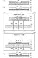
図1は本発明の一実施の形態に係る熱処理装置の構成を示す模式的断面図である。図1に示すように、熱処理装置300は、チャンバ310を備える。チャンバ310は、底板311、周壁312および蓋313により構成される。周壁312の下部開口を閉塞するように底板311が設けられる。底板311と周壁312とはシール部材Se1によりシールされる。周壁312の内側において、底板311上に加熱プレート320が設けられる。加熱プレート320内には、発熱体(ヒータ)が設けられる。(1) Heat Treatment Device FIG. 1 is a schematic cross-sectional view showing a configuration of a heat treatment device according to an embodiment of the present invention. As shown in FIG. 1, the
蓋313の中心部には、供給口314が形成される。蓋313の下側には、複数の孔を有する拡散板315が取り付けられる。蓋313は、周壁312の上部開口を閉塞するように設けられる。蓋313と周壁312とはシール部材Se2によりシールされる。 A
蓋313は蓋昇降装置330に接続される。蓋昇降装置330によって蓋313が上方位置と下方位置との間で昇降される。蓋313が上方位置にある場合、周壁312の上部開口が開放される。蓋313が下方位置にある場合、周壁312の上部開口が閉塞される。この場合、蓋313の下面がシール部材Se2に密着し、チャンバ310の内部に気密な処理空間が形成される。 The
加熱プレート320の上面には、複数(例えば3つ)のプロキシミティボール321が設けられる。加熱プレート320の上面が加熱面となる。加熱プレート320の上面から一定距離(例えば0.1mm)だけ離間するように複数のプロキシミティボール321上に基板Wが載置される。加熱プレート320を上下方向に貫通するように、複数(例えば3つ)の貫通孔322が設けられる。底板311の下面には、シール部材Se3を介して補助板340が配置される。シール部材Se1,Se2,Se3は例えばOリングからなる。補助板340には底板311の複数の貫通孔322に対応する複数の貫通孔が形成される。底板311の複数の貫通孔を取り囲むように底板311の下面に複数の円筒部材341が取り付けられる。 A plurality (for example, three) of
複数の円筒部材341の内部、底板311の複数の貫通孔および加熱プレート320の複数の貫通孔322に複数(例えば3つ)の支持ピン350がそれぞれ挿入される。複数の支持ピン350の上端上に基板Wが支持される。各支持ピン350と円筒部材341との間にはシール部材Se4が設けられる。シール部材Se4は、例えば金属シールである。 A plurality (for example, three) of support pins 350 are inserted into the inside of the plurality of
補助板340の下方には、連結部材351が配置される。複数の支持ピン350は上下方向に延びるように連結部材351に取り付けられる。連結部材351は、支持ピン昇降装置352と接続される。支持ピン昇降装置352は、例えばエアシリンダにより構成される。支持ピン昇降装置352により、複数の支持ピン350が上方位置と下方位置との間で一体的に昇降される。シール部材Se1〜Se4によりチャンバ310の内部に気密な処理空間が形成される。 A connecting
蓋313の供給口314には、共通供給管PCの一端が接続される。共通供給管PCの他端には、ガス供給管PGの一端および複数の溶剤供給管PSの一端が接続される。ガス供給管PGにはガス供給バルブV1が介挿され、複数の溶剤供給管PSには溶剤供給バルブV2がそれぞれ介挿される。ガス供給管PGの他端は、ガス供給源GSに接続される。複数の溶剤供給管PSの他端は溶剤供給源SSにそれぞれ接続される。ガス供給源GSは、窒素ガス等の不活性ガスを供給する。複数の溶剤供給源SSは、それぞれ異なる種類の有機溶剤(以下、溶剤と略記する。)を気化された状態で供給する。例えば、溶剤としては、トルエン、ヘプタン、アセトン、プロピレングリコールモノメチルエーテルアセテート(PGMEA)、プロピレングリコールモノメチルエーテル(PGME)、シクロヘキサノン、イソプロピルアルコール(IPA)、二硫化炭素またはテトラヒドロフラン等が用いられる。 One end of the common supply pipe PC is connected to the
ガス供給バルブV1が開かれることにより、ガス供給源GSから不活性ガスがガス供給管PG、共通供給管PCおよび供給口314を通してチャンバ310内に供給される。1または複数の溶剤供給バルブV2が選択的に開かれることにより、その溶剤供給バルブV2に対応する溶剤供給源SSから気化された溶剤が溶剤供給管PS、共通供給管PCおよび蓋313の供給口314を通してチャンバ310内に供給される。これにより、複数種類の溶剤のうち選択された1種類の溶剤または混合された複数種類の溶剤が基板Wに供給される。ガス供給バルブV1が開かれるとともに1または複数の溶剤供給バルブV2が開かれることにより、不活性ガスと選択された1種類または複数種類の溶剤とが混合されてチャンバ310内に供給される。 When the gas supply valve V1 is opened, the inert gas is supplied from the gas supply source GS into the
周壁312には、検出孔316が形成される。検出孔316は検出管Pdを通して溶剤濃度センサ380に接続される。検出管Pdには、検出バルブV3が介挿される。溶剤濃度センサ380は、チャンバ310内の溶剤濃度を検出する。 A
周壁312の下部には、外周面に沿って複数の排気口318が設けられる。排気口318は、排気管Pe1,Pe2を通して外部排気部EXに接続される。排気管Pe2には、排気バルブV4および排気ポンプPMが介挿される。排気ポンプPMが作動しかつ排気バルブV4が開かれると、チャンバ310内の雰囲気が排気管Pe1,Pe2を通して外部排気部EXに導かれる。これにより、チャンバ310内が減圧される。 A plurality of
熱処理装置300は熱処理コントローラ390を備える。熱処理コントローラ390は、CPU(中央演算処理装置)、ROM(リードオンリメモリ)およびRAM(ランダムアクセスメモリ)等を含む。ROMには、制御プログラムが記憶される。CPUはROMに記憶された制御プログラムをRAMを用いて実行することにより熱処理装置300の各部の動作を制御する。 The
(2)熱処理装置の制御系統
図2は図1の熱処理装置300の制御系統の構成を示すブロック図である。図2には、熱処理コントローラ390の機能的な構成が示される。熱処理コントローラ390は、熱処理温度制御部391、蓋開閉制御部392、支持ピン昇降制御部393、排気制御部394、ガス供給制御部395、溶剤供給制御部396、溶剤濃度取得部397および時間計測部398を含む。図2の熱処理コントローラ390の各部の機能は、CPUが制御プログラムを実行することにより実現される。(2) Control system of heat treatment apparatus FIG. 2 is a block diagram showing a configuration of a control system of the
熱処理温度制御部391は加熱プレート320の温度を制御し、蓋開閉制御部392は蓋昇降装置330の動作を制御し、支持ピン昇降制御部393は支持ピン昇降装置352の動作を制御する。排気制御部394は排気バルブV4の開閉を制御し、ガス供給制御部395はガス供給バルブV1の開閉を制御し、溶剤供給制御部396は溶剤供給バルブV2の開閉を制御する。溶剤濃度取得部397は溶剤濃度センサ380から溶剤濃度を取得し、取得した溶剤濃度を排気制御部394、ガス供給制御部395および溶剤供給制御部396に与える。時間計測部398は時間経過を計測する。各制御部391〜396の動作タイミングは、時間計測部398により計測される時間経過に基づいて決定される。 The heat treatment
(3)基板処理方法の一例
図3は図1の熱処理装置300を用いた基板処理方法の一例を示す模式的断面図である。図3(a)〜(e)の工程のうち図3(c),(d)の工程が図1の熱処理装置300により行われる。本例では、微細なホールパターンの形成方法が示される。(3) Example of Substrate Processing Method FIG. 3 is a schematic cross-sectional view showing an example of a substrate processing method using the
まず、図3(a)に示すように、基板Wの上面を覆うように下地層L1が形成され、下地層L1上に例えばフォトレジストからなるガイドパターンL2が形成される。本例では、ガイドパターンL2が円形の孔部Hを有する。次に、図3(b)に示すように、ガイドパターンL2の孔部H内の下地層L1上の領域に、DSA(Directed Self Assembly;誘導自己組織化)材料によりDSA膜L3が形成される。DSA材料は、複数種類の重合体によって構成されるブロック共重合体である。ブロック共重合体を構成する複数種類の重合体は、互いに非相溶であることが好ましい。 First, as shown in FIG. 3A, a base layer L1 is formed so as to cover the upper surface of the substrate W, and a guide pattern L2 made of, for example, a photoresist is formed on the base layer L1. In this example, the guide pattern L2 has a circular hole H. Next, as shown in FIG. 3B, a DSA film L3 is formed by a DSA (Directed Self Assembly) material in a region on the base layer L1 in the hole H of the guide pattern L2. .. The DSA material is a block copolymer composed of a plurality of types of polymers. It is preferable that the plurality of types of polymers constituting the block copolymer are incompatible with each other.
本実施の形態では、2種類の重合体から構成されるDSA材料が用いられる。2種類の重合体の組み合わせとして、例えば、ポリスチレン−ポリメチルメタクリレート(PS−PMMA)、ポリスチレン−ポリジメチルシロキサン(PS−PDMS)、ポリエチレン−ポリフェロセニルジメチルシラン(PS−PFS)、ポリスチレン−ポリエチレンオキシド(PS−PEO)、ポリスチレン−ポリビニルピリジン(PS−PVP)、ポリエチレン−ポリヒドロキシスチレン(PS−PHOST)、およびポリメチルメタクリレート−ポリメタクリレートポリヘドラルオリゴメリックシルセスキオキサン(PMMA−PMAPOSS)等が挙げられる。In this embodiment, a DSA material composed of two types of polymers is used. As a combination of the two polymers, for example, polystyrene-polymethylmethacrylate (PS-PMMA), polystyrene-polydimethylsiloxane (PS-PDMS), polyethylene-polyferrocenyldimethylsilane (PS-PFS), polystyrene-polyethylene oxide (PS-PEO), polystyrene - polyvinylpyridine (PS-PVP), polyethylene - polyhydroxystyrene (PS-PHOST), and polymethyl methacrylate - polymethacrylate polyhedral oligomeric ShiRuse Sukiokisan (PMMA-PMAPOSS) or the like can be mentioned Be done.
次に、図3(c)に示すように、図1の熱処理装置300のチャンバ310内に基板Wが搬入される。加熱プレート320の上面(加熱面)の温度は、予め熱処理温度に設定される。ここで、熱処理温度とは、DSA材料のミクロ相分離が生じる温度である。熱処理温度は、200℃以上であり、例えば250℃〜300℃である。熱処理温度は、本例に限定されず、DSA膜においてミクロ相分離が生じるようにDSA膜の材料に応じて決定される。 Next, as shown in FIG. 3C, the substrate W is carried into the
基板Wは、加熱プレート320の上面から上方へ離間した状態で支持ピン350上に支持される。この状態で、チャンバ310内の雰囲気(空気)が溶剤と不活性ガス(本実施の形態では窒素ガス)との混合ガス(以下、溶剤含有気体と呼ぶ。)で置換される。これにより、後述する雰囲気の中性化が行われる。溶剤含有気体中の溶剤の濃度は、例えば200ppm〜800ppmである。溶剤の濃度は、本例に限定されず、DSA膜の材料に応じて決定される。このとき、基板Wは加熱プレート320から離間しているので、基板Wの温度は、DSA膜L3においてミクロ相分離が生じる温度よりも低い温度(ミクロ相分離が生じない温度)に保たれる。そのため、DSA膜L3においてミクロ相分離は生じない。例えば、基板Wの温度は200℃よりも低い温度に保たれる。 The substrate W is supported on the
ここで、DSA膜L3を構成する一方の重合体に対する溶剤の親和性とDSA膜L3を構成する他方の重合体に対する溶剤の親和性とはほぼ等しい。あるいは、DSA膜L3を構成する2種類の重合体に対する親和性がほぼ等しくなるように一種類または複数種類の溶剤が選択される。例えば、溶剤として、シクロヘキサノンとPGMEAとの混合溶剤、またはPGMEAとPGMEとの混合溶剤が用いられる。溶剤によりDSA膜L3に接する雰囲気が中性化される。ここで、雰囲気の中性化とは、DSA膜を構成する一の重合体に対する溶剤の親和性とDSA膜を構成する他の重合体に対する溶剤の親和性とをほぼ等しくすることを意味する。このように、基板Wを熱処理温度よりも低い温度(ミクロ相分離が生じない温度)に保ちつつ溶剤含有気体中で一定時間保持する。ここで、一定時間は、例えば1秒〜5秒であるが、これに限定されず、DSA膜の材料および形成すべきパターン等に応じて予め設定される。 Here, the affinity of the solvent for one polymer constituting the DSA film L3 and the affinity of the solvent for the other polymer constituting the DSA film L3 are substantially equal. Alternatively, one or more solvents are selected so that the affinity for the two polymers constituting the DSA film L3 is substantially equal. For example, as the solvent, a mixed solvent of cyclohexanone and PGMEA or a mixed solvent of PGMEA and PGMEA is used. The atmosphere in contact with the DSA film L3 is neutralized by the solvent. Here, neutralization of the atmosphere means that the affinity of the solvent for one polymer constituting the DSA film and the affinity of the solvent for the other polymer constituting the DSA film are made substantially equal. In this way, the substrate W is held in the solvent-containing gas for a certain period of time while being kept at a temperature lower than the heat treatment temperature (a temperature at which microphase separation does not occur). Here, the fixed time is, for example, 1 second to 5 seconds, but is not limited to this, and is set in advance according to the material of the DSA film, the pattern to be formed, and the like.
その後、図3(d)に示すように、複数の支持ピン350が下降することにより、基板Wが加熱プレート320の上面(加熱面)上(加熱プレート320の上面に近接する位置)に支持される。加熱プレート320の上面の温度は予め熱処理温度に設定されているので、基板W上のDSA膜L3においてミクロ相分離が生じる。その結果、一方の重合体からなるパターンP1および他方の重合体からなるパターンP2が形成される。本例では、ガイドパターンL2の円形の孔部Hの内周面に沿うように、円環状のパターンP1が形成されるとともに、パターンP1の内側に円形のパターンP2が形成される。この場合、溶剤によってDSA膜L3を膨潤させることができるので、DSA材料のミクロ相分離を促進させることができる。 After that, as shown in FIG. 3D, the plurality of support pins 350 are lowered to support the substrate W on the upper surface (heating surface) of the heating plate 320 (position close to the upper surface of the heating plate 320). To. Since the temperature of the upper surface of the
次に、ミクロ相分離後のDSA膜L3の全面に露光処理が行われることにより、一方の重合体と他方の重合体との間の結合が切断され、パターンP1とパターンP2とが分離される。次に、基板W上のDSA膜L3に現像処理が行われることにより、図3(e)に示すように、パターンP2が除去される。最終的に、基板W上に円形の孔部hを有するパターンP1(ホールパターン)が残存する。 Next, by performing an exposure treatment on the entire surface of the DSA film L3 after the microphase separation, the bond between one polymer and the other polymer is broken, and the pattern P1 and the pattern P2 are separated. .. Next, the DSA film L3 on the substrate W is subjected to a developing process, so that the pattern P2 is removed as shown in FIG. 3 (e). Finally, the pattern P1 (hole pattern) having the circular hole portion h remains on the substrate W.
図4は熱処理前の雰囲気の中性化の有無によるミクロ相分離後のパターンの違いを説明するための模式図である。図4(a),(b)は加熱プレート320による基板Wの熱処理前に雰囲気の中性化を行わなかった場合に形成されるパターンの例を示し、図4(c)は加熱プレート320による基板Wの熱処理前に雰囲気の中性化を行った場合に形成されるパターンの例を示す。 FIG. 4 is a schematic diagram for explaining the difference in the pattern after the microphase separation depending on the presence or absence of neutralization of the atmosphere before the heat treatment. 4 (a) and 4 (b) show an example of a pattern formed when the atmosphere is not neutralized before the heat treatment of the substrate W by the
ここで、DSA膜L3を構成する一方の重合体は、他方の重合体に比べて空気に対して高い親和性を有する。以下、DSA膜L3を構成する2種類の重合体のうち空気に対する親和性が高い重合体を第1の重合体と呼び、空気に対する親和性が低い重合体を第2の重合体と呼ぶ。 Here, one polymer constituting the DSA film L3 has a higher affinity for air than the other polymer. Hereinafter, of the two types of polymers constituting the DSA film L3, the polymer having a high affinity for air is referred to as a first polymer, and the polymer having a low affinity for air is referred to as a second polymer.
熱処理前に雰囲気の中性化を行わなかった場合、熱処理の際に第1の重合体が雰囲気に接するようにミクロ相分離が行われやすい。図4(a)の例では、第1の重合体のパターンP10a、第2の重合体のパターンP20および第1の重合体のパターンP10bが層状に形成される。図4(b)の例では、第1の重合体のパターンP11aが環状に形成されるとともに、パターンP11aの内側に第2の重合体の円形のパターンP21が形成され、パターンP11a,P21を覆うように第1の重合体のパターンP11bが層状に形成される。これらの場合、露光処理および現像処理により所望のホールパターンを形成することができない。 If the atmosphere is not neutralized before the heat treatment, microphase separation is likely to be performed so that the first polymer comes into contact with the atmosphere during the heat treatment. In the example of FIG. 4A, the pattern P10a of the first polymer, the pattern P20 of the second polymer, and the pattern P10b of the first polymer are formed in layers. In the example of FIG. 4B, the pattern P11a of the first polymer is formed cyclically, and the circular pattern P21 of the second polymer is formed inside the pattern P11a to cover the patterns P11a and P21. As described above, the pattern P11b of the first polymer is formed in layers. In these cases, the desired hole pattern cannot be formed by the exposure treatment and the development treatment.
これに対して、熱処理前に雰囲気の中性化を行った場合、溶剤含有気体に対する第1の重合体の親和性と溶剤含有気体に対する第2の重合体の親和性とがほぼ等しくなる。それにより、図4(c)に示すように、第1の重合体のパターンP1が環状に形成されるとともに、パターンP1の内側に第2の重合体の円形のパターンP2が形成される。パターンP1,P2の上面を覆うパターンは形成されない。したがって、露光処理および現像処理によりパターンP2を除去することにより、所望のホールパターンを形成することができる。 On the other hand, when the atmosphere is neutralized before the heat treatment, the affinity of the first polymer for the solvent-containing gas and the affinity of the second polymer for the solvent-containing gas are almost equal. As a result, as shown in FIG. 4C, the pattern P1 of the first polymer is formed cyclically, and the circular pattern P2 of the second polymer is formed inside the pattern P1. No pattern is formed that covers the upper surfaces of the patterns P1 and P2. Therefore, a desired hole pattern can be formed by removing the pattern P2 by an exposure process and a developing process.
(4)熱処理装置300の動作
図5は図1の熱処理装置300の動作を示すフローチャートである。以下、図1、図2および図5を参照しながら図1の熱処理装置300の動作を説明する。(4) Operation of
図2の熱処理温度制御部391は、予め加熱プレート320の温度を熱処理温度に設定する(ステップS1)。次に、蓋開閉制御部392は、蓋313を開状態にするように蓋昇降装置330を制御する(ステップS2)。支持ピン昇降制御部393は、複数の支持ピン350を上昇させるように支持ピン昇降装置352を制御する。それにより、複数の支持ピン350が基板Wを受け取る(ステップS3)。その後、支持ピン昇降制御部393は、複数の支持ピン350をチャンバ310内に下降させるように支持ピン昇降装置352を制御する。それにより、複数の支持ピン350がチャンバ310内の加熱プレート320の上方位置で基板Wを支持する(ステップS4)。その後、蓋開閉制御部392は、蓋313を閉状態にするように蓋昇降装置330を制御する(ステップS5)。 The heat treatment
次に、排気制御部394は、排気バルブV4を開くことによりチャンバ310内を排気する(ステップS6)。また、ガス供給制御部395は、ガス供給バルブV1を開くことによりチャンバ310内に不活性ガスを供給する(ステップS7)。さらに、溶剤供給制御部396は、一または複数の溶剤供給バルブV2を開くことによりチャンバ310内に一種類または複数種類の溶剤を供給する(ステップS8)。これにより、チャンバ310内の空気が溶剤含有気体で置換される。なお、ステップS6,S7,S8の順序は図5の順序に限定されず、ステップS6,S7,S8が他の順序で行われてもよく、同時に行われてもよい。また、本例では、排気ポンプPMが予め動作を開始しているが、ステップS6の時点で排気ポンプPMが動作してもよい。 Next, the
溶剤濃度取得部397は、溶剤濃度センサ380から溶剤濃度を取得し、取得した溶剤濃度が予め設定された許容値以上であるか否かを判定する(ステップS9)。溶剤濃度の許容値は、例えば100ppmであるが、これに限定されず、DSA膜L3の材料または形成されるべきパターン等に応じて予め設定される。 The solvent
溶剤濃度取得部397は、溶剤濃度が許容値よりも低い場合にはステップS6に戻る。溶剤濃度が許容値以上になると、排気制御部394、ガス供給制御部395および溶剤供給制御部396が排気バルブV4、ガス供給バルブV1および溶剤供給バルブV2を閉じることにより、排気、不活性ガスの供給および溶剤の供給を停止する(ステップS10)。これにより、基板Wは、加熱プレート320から離間した状態で溶剤含有気体中で支持される。この場合、基板Wの温度は、DSA膜においてミクロ相分離が生じない温度に保たれる。 The solvent
この状態で、時間計測部398が予め設定された中性化処理時間が経過したか否かを判定する(ステップS11)。中性化処理時間が経過するまで、基板Wは、加熱プレート320から離間した状態で溶剤含有気体中で支持される。中性化処理時間は、DSA膜の材料および形成すべきパターン等に応じて予め設定される。 In this state, the
中性化処理時間が経過すると、支持ピン昇降制御部393は、複数の支持ピン350を下方位置まで下降させるように支持ピン昇降装置352を制御することにより、基板Wを加熱プレート320の上面まで下降させる(ステップS12)。それにより、基板Wの温度が熱処理温度まで上昇する。 When the neutralization processing time elapses, the support pin elevating
次に、時間計測部398が予め設定された熱処理時間が経過したか否かを判定する(ステップS13)。熱処理時間が経過するまで、基板Wに熱処理が行われる。それにより、DSA膜にミクロ相分離が生じる。 Next, the
熱処理時間が経過すると、支持ピン昇降制御部393は、複数の支持ピン350をチャンバ310内で上昇させるように支持ピン昇降装置352を制御する。それにより、複数の支持ピン350がチャンバ310内の加熱プレート320の上方位置で基板Wを支持する(ステップS14)。 After the heat treatment time elapses, the support pin elevating
この状態で、時間計測部398が予め設定された温度低下時間が経過したか否かを判定する(ステップS15)。温度低下時間は、基板Wの温度がミクロ相分離が生じない温度まで低下するために要する時間に設定される。温度低下時間が経過するまで、基板Wは、加熱プレート320から離間した状態で溶剤含有気体中で支持される。それにより、基板Wの温度が低下する。 In this state, the
温度低下時間が経過すると、排気制御部394は、排気バルブV4を開くことによりチャンバ310内を排気させ(ステップS16)、蓋開閉制御部392は、蓋313を開状態にするように蓋昇降装置330を制御する(ステップS17)。それにより、チャンバ310内の溶剤含有気体が空気で置換される。その後、支持ピン昇降制御部393は、複数の支持ピン350を上昇させるように支持ピン昇降装置352を制御する(ステップS18)。それにより、チャンバ310から基板Wを搬出することができる。 When the temperature drop time elapses, the
(5)基板処理装置の構成
図6は図1の熱処理装置300を備えた基板処理装置の模式的平面図である。図6および図7以降の所定の図には、位置関係を明確にするために互いに直交するX方向、Y方向およびZ方向を示す矢印を付している。X方向およびY方向は水平面内で互いに直交し、Z方向は鉛直方向に相当する。(5) Configuration of Substrate Processing Device FIG. 6 is a schematic plan view of the substrate processing apparatus provided with the
図6に示すように、基板処理装置100は、インデクサブロック11および処理ブロック12を備える。インデクサブロック11は、複数のキャリア載置部40および搬送部112を含む。各キャリア載置部40には、複数の基板Wを多段に収容するキャリアCがそれぞれ載置される。 As shown in FIG. 6, the
搬送部112には、主制御部114および搬送機構(搬送ロボット)115が設けられる。主制御部114は、基板処理装置100の種々の構成要素を制御する。搬送機構115は、基板Wを保持するためのハンド116を有する。搬送機構115は、ハンド116により基板Wを保持しつつその基板Wを搬送する。後述の図9に示すように、搬送部112には、キャリアCと搬送機構115との間で基板Wを受け渡すための開口部117が形成される。 The
搬送部112の側面には、メインパネルPNが設けられる。ユーザは、基板処理装置100における基板Wの処理状況等をメインパネルPNで確認することができる。また、メインパネルPNの近傍には、例えばキーボードからなる操作部(図示せず)が設けられる。ユーザは、操作部を操作することにより、基板処理装置100の動作設定等を行うことができる。 A main panel PN is provided on the side surface of the
処理ブロック12は、塗布現像処理部121、搬送部122および熱処理部123を含む。塗布現像処理部121および熱処理部123は、搬送部122を挟んで対向するように設けられる。搬送部122とインデクサブロック11との間には、基板Wが載置される基板載置部PASS1および後述する基板載置部PASS2〜PASS4(図9)が設けられる。搬送部122には、基板Wを搬送する搬送機構(搬送ロボット)127および後述する搬送機構(搬送ロボット)128(図9)が設けられる。 The
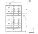
図7は図6の塗布現像処理部121の概略側面図である。図7に示すように、塗布現像処理部121には、現像処理室21,23および塗布処理室22,24が階層的に設けられる。現像処理室21,23の各々には、現像装置(デベロッパ)129が設けられる。塗布処理室22,24の各々には、塗布装置(コータ)139が設けられる。 FIG. 7 is a schematic side view of the coating
各現像装置129は、基板Wを保持するスピンチャック25およびスピンチャック25の周囲を覆うように設けられるカップ27を備える。本実施の形態では、各現像装置129に2組のスピンチャック25およびカップ27が設けられる。各スピンチャック25は、図示しない駆動装置(例えば、電動モータ)により回転駆動される。また、各現像装置129は、スピンチャック25により保持される基板Wに現像液を供給するためのノズル28を備える。本例では、複数のスピンチャック25にそれぞれ対応するように複数のノズル28が設けられるが、複数のスピンチャック25に対して共通のノズル28が用いられてもよい。 Each developing
各塗布装置139は、基板Wを保持するスピンチャック35およびスピンチャック35の周囲を覆うように設けられるカップ37を備える。本実施の形態では、各塗布装置139に2組のスピンチャック35およびカップ37が設けられる。各スピンチャック35は、図示しない駆動装置(例えば、電動モータ)により回転駆動される。また、各塗布装置139は、スピンチャック35により保持される基板Wに処理液を供給するためのノズル38を備える。本例では、複数のスピンチャック35にそれぞれ対応するように複数のノズル38が設けられるが、複数のスピンチャック35に対して共通のノズル38が用いられてもよい。 Each
塗布処理室22,24の塗布装置139においては、DSA材料からなる処理液が基板Wに塗布される。これにより、基板W上にDSA膜が形成される。現像処理室21,23の現像装置129においては、DSA膜が形成された基板Wに現像処理が行われる。具体的には、DSA膜が形成された基板Wに現像液が供給されることにより、DSA膜の不要な部分が除去される。現像液としては、例えば、トルエン、ヘプタン、アセトン、プロピレングリコールモノメチルエーテルアセテート(PGMEA)、プロピレングリコールモノメチルエーテル(PGME)、シクロヘキサノン、酢酸またはテトラヒドロフラン、イソプロピルアルコール(IPA)等が用いられる。 In the
図6および図7に示すように、塗布現像処理部121の一端には流体ボックス部50が設けられる。流体ボックス部50内には、現像装置129および塗布装置139への処理液および現像液の供給ならびに現像装置129および塗布装置139からの廃液および排気等に関する導管、継ぎ手、バルブ、流量計、レギュレータ、ポンプ、温度調節器等の流体関連機器が収納される。 As shown in FIGS. 6 and 7, a
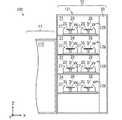
図8は図6の熱処理部123の概略側面図である。図8に示すように、熱処理部123は、上方に設けられる上段熱処理部301および下方に設けられる下段熱処理部302を有する。上段熱処理部301および下段熱処理部302の各々には、複数の熱処理装置300、複数の露光装置250および複数の冷却装置(クーリングプレート)CPが設けられる。 FIG. 8 is a schematic side view of the
熱処理装置300においては、上記のように、雰囲気の中性化が行われた後にDSA膜の形成後の基板Wに溶剤を用いた熱処理が行われる。露光装置250においては、溶剤熱処理後の基板Wに露光処理が行われる。冷却装置CPにおいては、DSA膜の形成前の基板Wおよび熱処理後の基板Wに冷却処理が行われる。 In the
図9は搬送部112,122の模式的側面図である。図9に示すように、搬送部122は、上段搬送室125および下段搬送室126を有する。上段搬送室125には搬送機構127が設けられ、下段搬送室126には搬送機構128が設けられる。 FIG. 9 is a schematic side view of the
搬送部112と上段搬送室125との間には、基板載置部PASS1,PASS2が設けられ、搬送部112と下段搬送室126との間には、基板載置部PASS3,PASS4が設けられる。 The substrate mounting portions PASS1 and PASS2 are provided between the
基板載置部PASS1,PASS3には、インデクサブロック11から処理ブロック12へ搬送される基板Wが載置される。基板載置部PASS2,PASS4には、処理ブロック12からインデクサブロック11へ搬送される基板Wが載置される。 The substrate W transported from the
搬送機構127,128の各々は、ガイドレール131,132,133、移動部材134、回転部材135およびハンドH1,H2を備える。ガイドレール131,132は、上下方向に延びるようにそれぞれ設けられる。ガイドレール133は、ガイドレール131とガイドレール132と間で水平方向(X方向)に延びるように設けられ、上下動可能にガイドレール131,132に取り付けられる。移動部材134は、水平方向(X方向)に移動可能にガイドレール133に取り付けられる。 Each of the
移動部材134の上面に、回転部材135が回転可能に設けられる。回転部材135には、基板Wを保持するためのハンドH1およびハンドH2が取り付けられる。ハンドH1,H2は、回転部材135を基準に進退可能に構成される。 A rotating
このような構成により、搬送機構127,128の各々は、ハンドH1,H2を用いて基板Wを保持し、X方向およびZ方向に移動して基板Wを搬送することができる。搬送機構127は、基板載置部PASS1,PASS2、現像処理室21(図7)、塗布処理室22(図7)および上段熱処理部301(図8)の間で基板Wを搬送する。搬送機構128は、基板載置部PASS3,PASS4、現像処理室23(図7)、塗布処理室24(図7)および下段熱処理部302(図8)の間で基板Wを搬送する。With such a configuration, each of the
(6)基板処理装置100の動作
基板処理装置100の動作について説明する。まず、インデクサブロック11のキャリア載置部40(図6)に、初期状態(図3(a))の基板Wが収容されたキャリアCが載置される。搬送機構115は、キャリアCから基板載置部PASS1および基板載置部PASS3(図9)に交互に初期状態の基板Wを搬送する。(6) Operation of the
基板載置部PASS1に載置された基板Wは、搬送機構127(図9)のハンドH1により取り出される。次に、搬送機構127(図9)は、ハンドH2により上段熱処理部301(図8)の所定の冷却装置CPから冷却処理後の基板Wを取り出し、ハンドH1に保持される基板Wをその冷却装置CPに搬入する。この場合、冷却装置CPにおいて、基板Wの温度がDSA膜L3の形成に適した温度に調整される。 The substrate W mounted on the substrate mounting portion PASS1 is taken out by the hand H1 of the transport mechanism 127 (FIG. 9). Next, the transport mechanism 127 (FIG. 9) takes out the substrate W after the cooling treatment from the predetermined cooling device CP of the upper heat treatment unit 301 (FIG. 8) by the hand H2, and cools the substrate W held by the hand H1. Carry it into the device CP. In this case, in the cooling device CP, the temperature of the substrate W is adjusted to a temperature suitable for forming the DSA film L3.
次に、搬送機構127(図9)は、ハンドH1により塗布処理室22(図7)のスピンチャック35上からDSA膜L3が形成された後の基板W(図3(b))を取り出し、ハンドH2に保持される冷却処理後の基板Wをそのスピンチャック35上に載置する。塗布処理室22において、塗布装置139(図7)により、基板W上にDSA膜L3が形成される(図3(b))。 Next, the transport mechanism 127 (FIG. 9) takes out the substrate W (FIG. 3 (b)) after the DSA film L3 is formed from the
次に、搬送機構127(図9)は、ハンドH2により上段熱処理部301(図8)の所定の熱処理装置300から熱処理後の基板W(図3(d))を取り出し、ハンドH1に保持されるDSA膜L3の形成後の基板Wをその熱処理装置300に搬入する。熱処理装置300において、基板Wの熱処理が行われる(図3(c),(d))。 Next, the transport mechanism 127 (FIG. 9) takes out the heat-treated substrate W (FIG. 3 (d)) from the predetermined
次に、搬送機構127(図9)は、ハンドH1により上段熱処理部301(図8)の所定の冷却装置CPから冷却処理後の基板Wを取り出し、ハンドH2に保持される熱処理後の基板Wをその冷却装置CPに搬入する。この場合、冷却装置CPにおいて、基板Wの温度が露光処理に適した温度に調整される。 Next, the transport mechanism 127 (FIG. 9) takes out the substrate W after the cooling treatment from the predetermined cooling device CP of the upper heat treatment unit 301 (FIG. 8) by the hand H1, and the substrate W after the heat treatment is held by the hand H2. Is carried into the cooling device CP. In this case, in the cooling device CP, the temperature of the substrate W is adjusted to a temperature suitable for the exposure process.
次に、搬送機構127(図9)は、ハンドH2により上段熱処理部301(図8)の所定の露光装置250から露光処理後の基板Wを取り出し、ハンドH1に保持される冷却処理後の基板Wをその露光装置250に搬入する。露光装置250において、熱処理後の基板Wに露光処理が行われる。 Next, the transport mechanism 127 (FIG. 9) takes out the substrate W after the exposure treatment from the
次に、搬送機構127(図9)は、ハンドH1により現像処理室21(図7)のスピンチャック25上から現像処理後の基板W(図3(e))を取り出し、ハンドH2に保持される露光処理後の基板Wをそのスピンチャック35上に載置する。現像処理室21において、現像装置129により、露光処理後の基板Wに現像処理が行われる(図3(e))。その後、搬送機構127は、ハンドH1に保持される現像処理後の基板Wを基板載置部PASS2(図9)に載置する。 Next, the transport mechanism 127 (FIG. 9) takes out the developed substrate W (FIG. 3 (e)) from the
搬送機構127が上記の処理を繰り返すことにより、処理ブロック12内において複数の基板Wに所定の処理が連続的に行われる。By repeating the above processing by the
搬送機構128は、搬送機構127と同様の動作により、基板載置部PASS3,PASS4、現像処理室23、塗布処理室24および下段熱処理部302に対して基板Wの搬入および搬出を行う。現像処理室23、塗布処理室24および下段熱処理部302において、現像処理室21、塗布処理室22および上段熱処理部301と同様の処理が行われる。 The
このように、本実施の形態においては、搬送機構127によって搬送される基板Wは、現像処理室21、塗布処理室22および上段熱処理部301において処理され、搬送機構128によって搬送される基板Wは、現像処理室23、塗布処理室24および下段熱処理部302において処理される。この場合、上段の処理部(現像処理室21、塗布処理室22および上段熱処理部301)および下段の処理部(現像処理室23、塗布処理室24および下段熱処理部302)において並行して基板Wの処理を行うことができる。 As described above, in the present embodiment, the substrate W transported by the
(7)効果
本実施の形態に係る基板処理装置100においては、塗布装置139により基板W上にDSA膜L3が形成される。次に、熱処理装置300のチャンバ310内で基板Wが加熱プレート320から離間された状態で溶剤含有気体中に一定時間保持される。それにより、熱処理装置300のチャンバ310内で熱処理前に雰囲気の中性化が行われる。その後、基板W上のDSA膜L3に熱処理が行われる。この場合、熱処理前にDSA膜L3に接する雰囲気が中性化されているので、ミクロ相分離を適切に生じさせることができる。その結果、基板W上に微細なパターンを精度よく形成することができる。(7) Effect In the
また、雰囲気の中性化の際に基板Wが加熱プレート320の上方位置に保持され、熱処理の際に基板Wが加熱プレート320上に保持される。それにより、予め加熱プレート320の温度を変化させることなく、雰囲気の中性化の際に基板Wの温度をミクロ相分離を生じない温度に保つことができる。したがって、スループットの低下が生じない。 Further, the substrate W is held above the
さらに、チャンバ310内に溶剤含有気体が供給される際にチャンバ310内が減圧されるので、チャンバ310内の空気を溶剤含有気体に効率良く置換できる。それにより、ミクロ相分離により形成されるパターンに欠陥が生じることが防止される。 Further, since the pressure inside the
また、基板Wに熱処理が行われた後に、基板Wの温度が低下するまで基板Wが加熱プレート320の上方位置で保持された後、チャンバ310内の溶剤含有気体が空気で置換される。それにより、チャンバ310内の溶剤含有気体が空気で置換されるときに基板W上のDSA膜においてミクロ相分離が生じない。したがって、空気中でミクロ相分離によりパターンに欠陥が生じることが防止される。Further, after the substrate W is heat-treated, the substrate W is held above the
(8)他の実施の形態
上記実施の形態では、熱処理前の雰囲気の中性化の際に基板Wを加熱プレート320の上面から上方に離間させるが、本発明は、これに限定されない。熱処理前の雰囲気の中性化の際に基板Wを加熱プレート320の側方に離間させてよい。(8) Other Embodiments In the above embodiment, the substrate W is separated upward from the upper surface of the
上記実施の形態では、基板処理装置100が露光装置250および現像装置129を備えるが、露光装置250および現像装置129の少なくとも一方が基板処理装置100の外部装置として設けられてもよい。 In the above embodiment, the
(9)請求項の各構成要素と実施の形態の各要素との対応
以下、請求項の各構成要素と実施の形態の各要素との対応の例について説明するが、本発明は下記の例に限定されない。(9) Correspondence between Each Component of Claim and Each Element of Embodiment Hereinafter, an example of correspondence between each component of claim and each element of embodiment will be described, but the present invention describes the following examples. Not limited to.
上記実施の形態では、加熱プレート320が加熱部の例であり、ガス供給管PG、ガス供給バルブV1、溶剤供給管PSおよび溶剤供給バルブV2が気体供給部の例であり、支持ピン350、連結部材351および支持ピン昇降装置352が基板移動部の例であり、熱処理コントローラ390および支持ピン昇降制御部393が移動制御部の例であり、支持ピン350が支持部材の例である。加熱プレート320の上方位置が第1の位置の例であり、加熱プレート320に近接した位置が第2の位置の例であり、排気管Pe1,Pe2、排気バルブV4および排気ポンプPMが排気部または置換部の例である。 In the above embodiment, the
請求項の各構成要素として、請求項に記載されている構成または機能を有する他の種々の要素を用いることもできる。
(参考形態)
(1)第1の参考形態に係る熱処理装置は、誘導自己組織化材料からなる処理膜が形成された基板に熱処理を行う熱処理装置であって、基板に予め設定された熱処理温度で熱処理を行う加熱部と、加熱部を収容するチャンバと、有機溶剤を含む溶剤含有気体をチャンバ内に供給する気体供給部と、チャンバ内で加熱部により基板に熱処理が行われない第1の位置と加熱部により基板に熱処理が行われる第2の位置とに基板を移動させる基板移動部と、チャンバ内に気体供給部により供給された溶剤含有気体が存在する状態で基板が第1の位置で保持されるように基板移動部を制御した後、チャンバ内に溶剤含有気体が存在する状態で基板が第2の位置で保持されるように基板移動部を制御する移動制御部とを備える。
その熱処理装置においては、チャンバ内に溶剤含有気体が存在する状態で、第1の位置で熱処理が行われずに基板が保持される。それにより、基板上の処理膜が溶剤含有気体に接する。誘導自己組織化材料を構成する複数の重合体に対する有機溶剤の親和性は互いに近い。すなわち、処理膜に接する雰囲気が中性化されている。その後、第2の位置で基板に熱処理が行われる。それにより、処理膜においてミクロ相分離が生じる。この場合、熱処理前に処理膜に接する雰囲気が中性化されているので、誘導自己組織化材料を構成する一の重合体のみが雰囲気に接する層を形成することが防止される。その結果、誘導自己組織化材料の適切なミクロ相分離を生じさせることが可能となる。
(2)加熱部は、加熱面を有する加熱プレートを含み、第1の位置は加熱プレートの加熱面の上方位置であり、第2の位置は加熱プレートにより熱処理が行われるように加熱面に近接した位置であり、基板移動部は、基板を支持しつつチャンバ内で基板を加熱面の上方位置と加熱面に近接した位置とに移動させる支持部材を含んでもよい。
この場合、基板を上下移動させることにより雰囲気の中性化および基板の熱処理を簡単な構成で行うことができる。
(3)基板が第1の位置にあるときの基板の温度は、処理膜においてミクロ相分離が生じない温度であってもよい。この場合、雰囲気の中性化の際に、処理膜においてミクロ相分離が生じることが防止される。
(4)熱処理装置は、基板が基板移動部により第1の位置で保持された状態で、チャンバ内の空気を排出することによりチャンバ内を減圧する排気部をさらに備え、気体供給部は、排気部により減圧されたチャンバ内に溶剤含有気体を供給してもよい。
この場合、空気を溶剤含有気体に効率良く置換することができる。それにより、ミクロ相分離により形成されるパターンに欠陥が生じにくくなる。
(5)熱処理装置は、チャンバ内の溶剤濃度を検出する溶剤濃度検出部をさらに備え、排気部および気体供給部は、溶剤濃度検出部により検出され溶剤濃度が予め設定された許容値以上になるようにチャンバ内を排気するとともにチャンバ内に溶剤含有気体を供給してもよい。
この場合、溶剤含有気体中の溶剤濃度が許容値以上になるので、ミクロ相分離により形成されるパターンに欠陥が生じることが防止される。
(6)移動制御部は、基板に加熱部により熱処理が行われた後に、基板の温度が処理膜のミクロ相分離が生じない温度に低下するまで基板が第1の位置で保持されるように基板移動部を制御し、熱処理装置は、熱処理後の基板移動部による基板の保持後にチャンバ内の溶剤含有気体を空気で置換する置換部をさらに備えてもよい。
この場合、チャンバ内の溶剤含有気体が空気で置換されるときに基板上の処理膜においてミクロ相分離が生じない。したがって、空気中でミクロ相分離が生じることが防止される。
(7)溶剤含有気体は不活性ガスを含んでもよい。
(8)本参考形態に係る基板処理装置は、基板に誘導自己組織化材料を塗布することにより基板上に処理膜を形成する塗布装置と、塗布装置により基板上に形成された処理膜に熱処理を行う上記の熱処理装置とを備える。
その基板処理装置によれば、基板上に誘導自己組織化材料からなる処理膜を形成することができるとともに、処理膜において誘導自己組織化材料の適切なミクロ相分離を生じさせることが可能となる。
(9)基板処理装置は、熱処理装置による熱処理後の処理膜に露光処理を行う露光装置と、露光装置による露光処理後の処理膜に現像処理を行う現像装置とをさらに備える。
この場合、誘導自己組織化材料の適切なミクロ相分離が生じた処理膜にパターンを形成することができる。
(10)本参考形態に係る熱処理方法は、誘導自己組織化材料からなる処理膜が形成された基板に熱処理を行う熱処理方法であって、加熱部を収容するチャンバ内において有機溶剤を含む溶剤含有気体が存在する状態で加熱部により熱処理が行われない第1の位置で基板を保持する工程と、第1の位置で基板を保持した後、チャンバ内において加熱部により熱処理が行われる第2の位置で基板を保持する工程とを含む。
この熱処理方法においては、処理膜に接する雰囲気が中性化されているので、誘導自己組織化材料を構成する一の重合体のみが雰囲気に接する層を形成することが防止される。その結果、誘導自己組織化材料の適切なミクロ相分離を生じさせることが可能となる。
(11)本参考形態に係る基板処理方法は、塗布装置において、基板上に誘導自己組織化材料からなる処理膜を形成する工程と、処理膜が形成された基板に上記の熱処理方法により熱処理を行う工程とを含む。
その基板処理方法によれば、基板上に誘導自己組織化材料からなる処理膜を形成することができるとともに、処理膜において誘導自己組織化材料の適切なミクロ相分離を生じさせることが可能となる。As each component of the claim, various other components having the structure or function described in the claim can also be used.
(Reference form)
(1) The heat treatment apparatus according to the first reference embodiment is a heat treatment apparatus that heat-treats a substrate on which a treated film made of an inductive self-assembling material is formed, and performs heat treatment at a heat treatment temperature preset on the substrate. A heating unit, a chamber accommodating the heating unit, a gas supply unit that supplies a solvent-containing gas containing an organic solvent into the chamber, and a first position and a heating unit in which the heat treatment is not performed on the substrate by the heating unit in the chamber. The substrate is held in the first position in the presence of the substrate moving portion that moves the substrate to the second position where the heat treatment is performed on the substrate and the solvent-containing gas supplied by the gas supply unit in the chamber. After controlling the substrate moving unit as described above, the movement control unit is provided to control the substrate moving unit so that the substrate is held at the second position in the state where the solvent-containing gas is present in the chamber.
In the heat treatment apparatus, the substrate is held in the state where the solvent-containing gas is present in the chamber without performing the heat treatment at the first position. As a result, the treated film on the substrate comes into contact with the solvent-containing gas. The affinity of the organic solvent for the plurality of polymers constituting the inductive self-assembling material is close to each other. That is, the atmosphere in contact with the treated membrane is neutralized. After that, the substrate is heat-treated at the second position. As a result, microphase separation occurs in the treated membrane. In this case, since the atmosphere in contact with the treated membrane is neutralized before the heat treatment, it is possible to prevent only one polymer constituting the induced self-assembling material from forming a layer in contact with the atmosphere. As a result, it is possible to cause appropriate microphase separation of the induced self-assembling material.
(2) The heating unit includes a heating plate having a heating surface, the first position is a position above the heating surface of the heating plate, and the second position is close to the heating surface so that the heat treatment is performed by the heating plate. The substrate moving portion may include a support member that moves the substrate to a position above the heating surface and a position close to the heating surface in the chamber while supporting the substrate.
In this case, by moving the substrate up and down, the atmosphere can be neutralized and the substrate can be heat-treated with a simple configuration.
(3) The temperature of the substrate when the substrate is in the first position may be a temperature at which microphase separation does not occur in the treated membrane. In this case, microphase separation is prevented from occurring in the treated membrane when the atmosphere is neutralized.
(4) The heat treatment apparatus further includes an exhaust unit that depressurizes the inside of the chamber by exhausting air in the chamber while the substrate is held in the first position by the substrate moving portion, and the gas supply unit exhausts. A solvent-containing gas may be supplied into the chamber decompressed by the unit.
In this case, the air can be efficiently replaced with the solvent-containing gas. As a result, defects are less likely to occur in the pattern formed by microphase separation.
(5) The heat treatment apparatus further includes a solvent concentration detecting unit for detecting the solvent concentration in the chamber, and the exhaust unit and the gas supply unit are detected by the solvent concentration detecting unit and the solvent concentration becomes equal to or higher than a preset allowable value. As described above, the inside of the chamber may be exhausted and the solvent-containing gas may be supplied into the chamber.
In this case, since the solvent concentration in the solvent-containing gas becomes equal to or higher than the allowable value, defects are prevented from occurring in the pattern formed by the microphase separation.
(6) The movement control unit holds the substrate in the first position until the temperature of the substrate drops to a temperature at which microphase separation of the treated film does not occur after the substrate is heat-treated by the heating unit. The heat treatment apparatus may further include a replacement part that controls the substrate moving part and replaces the solvent-containing gas in the chamber with air after the substrate is held by the substrate moving part after the heat treatment.
In this case, microphase separation does not occur in the treated membrane on the substrate when the solvent-containing gas in the chamber is replaced by air. Therefore, microphase separation is prevented from occurring in the air.
(7) The solvent-containing gas may contain an inert gas.
(8) The substrate processing apparatus according to this reference embodiment is a coating apparatus that forms a treated film on a substrate by applying an inductive self-assembling material to the substrate, and a heat treatment film formed on the substrate by the coating apparatus. The above-mentioned heat treatment apparatus is provided.
According to the substrate processing apparatus, it is possible to form a treated film made of the induced self-assembling material on the substrate and to cause appropriate microphase separation of the induced self-assembling material in the treated film. ..
(9) The substrate processing apparatus further includes an exposure apparatus that exposes the treated film after the heat treatment by the heat treatment apparatus and a developing apparatus that develops the processed film after the exposure treatment by the exposure apparatus.
In this case, a pattern can be formed on the treated membrane in which appropriate microphase separation of the induced self-assembling material has occurred.
(10) The heat treatment method according to the present reference embodiment is a heat treatment method in which a substrate on which a treated film made of an induced self-assembling material is formed is heat-treated, and contains a solvent containing an organic solvent in a chamber accommodating a heating portion. A step of holding the substrate in the first position where the heat treatment is not performed by the heating part in the presence of gas, and a second step in which the heat treatment is performed by the heating part in the chamber after holding the substrate in the first position. Includes a step of holding the substrate in position.
In this heat treatment method, since the atmosphere in contact with the treated membrane is neutralized, it is possible to prevent only one polymer constituting the induced self-assembling material from forming a layer in contact with the atmosphere. As a result, it is possible to cause appropriate microphase separation of the induced self-assembling material.
(11) The substrate treatment method according to the present reference embodiment is a step of forming a treatment film made of an induced self-assembling material on the substrate in a coating apparatus, and heat treatment is performed on the substrate on which the treatment film is formed by the above heat treatment method. Including the steps to be performed.
According to the substrate treatment method, a treated film made of the induced self-assembling material can be formed on the substrate, and appropriate microphase separation of the induced self-assembling material can be generated in the treated film. ..
本発明は、種々の基板の処理に利用可能である。 The present invention can be used to process various substrates.
100 基板処理装置
129 現像装置
131,132,133 ガイドレール
139 塗布装置
250 露光装置
300 熱処理装置
310 チャンバ
311 底板
312 周壁
313 蓋
314 供給口
315 拡散板
316 検出孔
318 排気口
320 加熱プレート
321 プロキシミティボール
322 貫通孔
330 蓋昇降装置
340 補助板
341 円筒部材
350 支持ピン
351 連結部材
352 支持ピン昇降装置
380 溶剤濃度センサ
390 熱処理コントローラ
391 熱処理温度制御部
392 蓋開閉制御部
393 支持ピン昇降制御部
394 排気制御部
395 ガス供給制御部
396 溶剤供給制御部
397 溶剤濃度取得部
398 時間計測部
EX 外部排気部
GS ガス供給源
L1 下地層
L2 ガイドパターン
L3 DSA膜
PC 共通供給管
PG ガス供給管
PS 溶剤供給管
PD 検出管
Pe1,Pe2 排気管
PM 排気ポンプ
SS 溶剤供給源
V1 ガス供給バルブ
V2 溶剤供給バルブ
V3 検出バルブ
V4 排気バルブ100
Claims (10)
Translated fromJapanese前記基板に予め設定された熱処理温度で熱処理を行う加熱部と、
前記加熱部を収容するチャンバと、
有機溶剤を含む溶剤含有気体を前記チャンバ内に供給する気体供給部と、
前記チャンバ内で前記加熱部により基板に熱処理が行われない第1の位置と前記加熱部により基板に前記熱処理が行われる第2の位置とに基板を移動させる基板移動部と、
前記チャンバ内に前記気体供給部により供給された溶剤含有気体が存在する状態で前記基板が前記第1の位置で保持されるように前記基板移動部を制御した後、前記チャンバ内に溶剤含有気体が存在する状態で前記基板が前記第2の位置で保持されるように前記基板移動部を制御する移動制御部とを備え、
前記第1の位置は、溶剤含有気体が存在する状態で前記加熱部の温度が前記熱処理温度である場合に前記処理膜にミクロ相分離が行われない位置に設定され、
前記第2の位置は、溶剤含有気体が存在する状態で前記加熱部の温度が前記熱処理温度である場合に前記処理膜にミクロ相分離が行われる位置に設定された、熱処理装置。A heat treatment apparatus that heat-treats a substrate on which a treated film made of an inductive self-organizing material is formed.
A heating unit that performs heat treatment at a heat treatment temperature set in advance on the substrate,
A chamber that houses the heating unit and
A gas supply unit that supplies a solvent-containing gas containing an organic solvent into the chamber,
A substrate moving unit that moves the substrate to a first position in the chamber where the heat treatment is not performed on the substrate by the heating unit and a second position where the heat treatment is performed on the substrate by the heating unit.
After controlling the substrate moving unit so that the substrate is held at the first position in a state where the solvent-containing gas supplied by the gas supply unit is present in the chamber, the solvent-containing gas is contained in the chamber. there a movement control unit for the substrate in a state that is present to control the substrate moving portion so as to be held in the secondposition,
The first position is set to a position where microphase separation is not performed on the treated membrane when the temperature of the heating portion is the heat treatment temperature in the presence of the solvent-containing gas.
The second position is a heat treatment apparatusset at a position where microphase separation is performed on the treated membrane when the temperature of the heating portion is the heat treatment temperature in the presence of a solvent-containing gas .
前記第1の位置は前記加熱プレートの前記加熱面の上方位置であり、前記第2の位置は前記加熱プレートにより前記熱処理が行われるように前記加熱面に近接した位置であり、
前記基板移動部は、前記基板を支持しつつ前記チャンバ内で前記基板を前記加熱面の上方位置と前記加熱面に近接した位置とに移動させる支持部材を含む、請求項1記載の熱処理装置。The heating unit includes a heating plate having a heating surface.
The first position is a position above the heating surface of the heating plate, and the second position is a position close to the heating surface so that the heat treatment is performed by the heating plate.
The heat treatment apparatus according to claim 1, wherein the substrate moving portion includes a support member that moves the substrate to a position above the heating surface and a position close to the heating surface in the chamber while supporting the substrate.
前記気体供給部は、前記排気部により減圧された前記チャンバ内に前記溶剤含有気体を供給する、請求項1または2記載の熱処理装置。A state in which the substrate is held in the first position by the substrate moving portion is further provided with an exhaust portion for depressurizing the inside of the chamber by discharging air in the chamber.
The heat treatment apparatus according to claim 1or 2 , wherein the gas supply unit supplies the solvent-containing gas into the chamber decompressed by the exhaust unit.
前記排気部および前記気体供給部は、前記溶剤濃度検出部により検出される溶剤濃度が予め設定された許容値以上になるように前記チャンバ内を排気するとともに前記チャンバ内に前記溶剤含有気体を供給する、請求項3記載の熱処理装置。Further provided with a solvent concentration detecting unit for detecting the solvent concentration in the chamber,
The exhaust unit and the gas supply unit exhaust the inside of the chamber so that the solvent concentration detected by the solvent concentration detection unit becomes equal to or higher than a preset allowable value, and supply the solvent-containing gas into the chamber. The heat treatment apparatus according to claim3 .
前記熱処理装置は、
前記熱処理後の前記基板移動部による前記基板の保持後に前記チャンバ内の溶剤含有気体を空気で置換する置換部をさらに備える、請求項1〜4のいずれか一項に記載の熱処理装置。In the movement control unit, after the heat treatment is performed on the substrate by the heating unit, the substrate is in the first position until the temperature of the substrate is lowered to a temperature at which microphase separation of the treated membrane does not occur. Control the substrate moving part so that it is held,
The heat treatment apparatus
The heat treatment apparatus according to any one of claims 1 to4 , further comprising a replacement portion for replacing the solvent-containing gas in the chamber with air after the substrate is held by the substrate moving portion after the heat treatment.
前記塗布装置により基板上に形成された処理膜に熱処理を行う請求項1〜6のいずれか一項に記載の熱処理装置とを備えた、基板処理装置。A coating device that forms a processing film on the substrate by applying an inductive self-assembling material to the substrate.
A substrate processing apparatus comprising the heat treatment apparatus according to any one of claims 1 to6 , which heat-treats a treated film formed on a substrate by the coating apparatus.
前記露光装置による露光処理後の処理膜に現像処理を行う現像装置とをさらに備えた、請求項7記載の基板処理装置。An exposure apparatus that exposes the treated film after heat treatment by the heat treatment apparatus,
The substrate processing apparatus according to claim7 , further comprising a developing apparatus for developing a processing film after exposure processing by the exposure apparatus.
加熱部を収容するチャンバ内において有機溶剤を含む有機溶剤含有気体が存在する状態で前記加熱部により熱処理が行われない第1の位置で前記基板を保持する工程と、
前記第1の位置で前記基板を保持した後、前記チャンバ内において前記加熱部により前記熱処理が行われる第2の位置で前記基板を保持する工程とを含み、
前記第1の位置は、溶剤含有気体が存在する状態で前記加熱部の温度が予め定められた熱処理温度である場合に前記処理膜にミクロ相分離が行われない位置に設定され、
前記第2の位置は、溶剤含有気体が存在する状態で前記加熱部の温度が前記熱処理温度である場合に前記処理膜にミクロ相分離が行われる位置に設定された、熱処理方法。A heat treatment method in which a substrate on which a treated film made of an inductive self-organizing material is formed is heat-treated.
A step of holding the substrate in a first position where heat treatment is not performed by the heating unit in a state where an organic solvent-containing gas containing an organic solvent is present in the chamber accommodating the heating unit.
After holding the substrate at the first position,seen including a step of holding the substrate at a second position in which the heat treatment is carried out by the heating unit in thechamber,
The first position is set to a position where microphase separation is not performed on the treated membrane when the temperature of the heating portion is a predetermined heat treatment temperature in the presence of the solvent-containing gas.
The second position is a heat treatment methodset to a position where microphase separation is performed on the treated membrane when the temperature of the heating portion is the heat treatment temperature in the presence of a solvent-containing gas .
前記処理膜が形成された前記基板に請求項9記載の熱処理方法により熱処理を行う工程とを含む、基板処理方法。In the coating device, the process of forming a treatment film made of an inductive self-assembling material on the substrate, and
A substrate processing method comprising a step of heat-treating the substrate on which the treatment film is formed by the heat treatment method according to claim9 .
Priority Applications (5)
| Application Number | Priority Date | Filing Date | Title |
|---|---|---|---|
| JP2016160561AJP6802667B2 (en) | 2016-08-18 | 2016-08-18 | Heat treatment equipment, substrate processing equipment, heat treatment method and substrate processing method |
| TW106123770ATWI653664B (en) | 2016-08-18 | 2017-07-17 | Thermal processing device, substrate processing apparatus, thermal processing method and substrate processing method |
| US15/669,202US10832925B2 (en) | 2016-08-18 | 2017-08-04 | Thermal processing device, substrate processing apparatus, thermal processing method and substrate processing method |
| CN201710704464.4ACN107768277B (en) | 2016-08-18 | 2017-08-16 | Heat treatment apparatus, substrate treatment apparatus, heat treatment method, and substrate treatment method |
| KR1020170104072AKR101994526B1 (en) | 2016-08-18 | 2017-08-17 | Thermal processing device, substrate processing apparatus, thermal processing method and substrate processing method |
Applications Claiming Priority (1)
| Application Number | Priority Date | Filing Date | Title |
|---|---|---|---|
| JP2016160561AJP6802667B2 (en) | 2016-08-18 | 2016-08-18 | Heat treatment equipment, substrate processing equipment, heat treatment method and substrate processing method |
Publications (2)
| Publication Number | Publication Date |
|---|---|
| JP2018029133A JP2018029133A (en) | 2018-02-22 |
| JP6802667B2true JP6802667B2 (en) | 2020-12-16 |
Family
ID=61191144
Family Applications (1)
| Application Number | Title | Priority Date | Filing Date |
|---|---|---|---|
| JP2016160561AActiveJP6802667B2 (en) | 2016-08-18 | 2016-08-18 | Heat treatment equipment, substrate processing equipment, heat treatment method and substrate processing method |
Country Status (5)
| Country | Link |
|---|---|
| US (1) | US10832925B2 (en) |
| JP (1) | JP6802667B2 (en) |
| KR (1) | KR101994526B1 (en) |
| CN (1) | CN107768277B (en) |
| TW (1) | TWI653664B (en) |
Families Citing this family (9)
| Publication number | Priority date | Publication date | Assignee | Title |
|---|---|---|---|---|
| JP6215426B1 (en)* | 2016-09-21 | 2017-10-18 | オリジン電気株式会社 | Heating device and method for manufacturing plate-like member |
| CN206573826U (en)* | 2017-03-23 | 2017-10-20 | 惠科股份有限公司 | Jacking device and alignment ultraviolet irradiation machine |
| CN109830452B (en)* | 2019-01-25 | 2021-04-27 | 武汉华星光电半导体显示技术有限公司 | Substrate baking device and substrate baking method |
| CN113314400A (en)* | 2020-02-27 | 2021-08-27 | 长鑫存储技术有限公司 | Semiconductor device and method for manufacturing the same |
| TWI867181B (en)* | 2020-03-30 | 2024-12-21 | 日商東京威力科創股份有限公司 | Substrate processing method, substrate processing device, and storage medium |
| JP7525338B2 (en)* | 2020-08-31 | 2024-07-30 | 株式会社Screenホールディングス | SUBSTRATE PROCESSING METHOD AND SUBSTRATE PROCESSING APPARATUS |
| JP2023032647A (en)* | 2021-08-27 | 2023-03-09 | 株式会社Kokusai Electric | Substrate processing device, manufacturing method for semiconductor device, and recording medium |
| JP2023167845A (en)* | 2022-05-13 | 2023-11-24 | 東京エレクトロン株式会社 | Heat treatment device, heat treatment method, and computer storage medium |
| JP7595051B2 (en)* | 2022-10-13 | 2024-12-05 | 株式会社Screenホールディングス | Reduced-pressure drying apparatus and reduced-pressure drying method |
Family Cites Families (13)
| Publication number | Priority date | Publication date | Assignee | Title |
|---|---|---|---|---|
| JP4030787B2 (en)* | 2002-03-04 | 2008-01-09 | 東京エレクトロン株式会社 | Substrate heating method, substrate heating apparatus, coating and developing apparatus |
| JP4199213B2 (en) | 2005-04-26 | 2008-12-17 | 株式会社東芝 | Substrate processing method |
| US20080217293A1 (en)* | 2007-03-06 | 2008-09-11 | Tokyo Electron Limited | Processing system and method for performing high throughput non-plasma processing |
| US8426313B2 (en) | 2008-03-21 | 2013-04-23 | Micron Technology, Inc. | Thermal anneal of block copolymer films with top interface constrained to wet both blocks with equal preference |
| JP5918122B2 (en) | 2012-04-06 | 2016-05-18 | 東京エレクトロン株式会社 | Pattern forming method, pattern forming apparatus, and computer-readable storage medium |
| JP2013222963A (en)* | 2012-04-17 | 2013-10-28 | Tokyo Ohka Kogyo Co Ltd | Conveying apparatus and coating apparatus |
| KR101970301B1 (en)* | 2012-07-11 | 2019-04-18 | 삼성전자주식회사 | Apparatus for testing wafer |
| JP6239813B2 (en) | 2012-07-18 | 2017-11-29 | 株式会社Screenセミコンダクターソリューションズ | Substrate processing apparatus and substrate processing method |
| JP5823424B2 (en)* | 2013-02-15 | 2015-11-25 | 東京エレクトロン株式会社 | Substrate processing method, program, computer storage medium, and substrate processing system |
| US20140231012A1 (en)* | 2013-02-15 | 2014-08-21 | Dainippon Screen Mfg, Co., Ltd. | Substrate processing apparatus |
| US8975009B2 (en) | 2013-03-14 | 2015-03-10 | Tokyo Electron Limited | Track processing to remove organic films in directed self-assembly chemo-epitaxy applications |
| JP6007141B2 (en)* | 2013-03-22 | 2016-10-12 | 東京エレクトロン株式会社 | Substrate processing apparatus, substrate processing method, program, and computer storage medium |
| JP2016111115A (en) | 2014-12-04 | 2016-06-20 | 東京エレクトロン株式会社 | Substrate processing method, program, computer storage medium and substrate processing system |
- 2016
- 2016-08-18JPJP2016160561Apatent/JP6802667B2/enactiveActive
- 2017
- 2017-07-17TWTW106123770Apatent/TWI653664B/enactive
- 2017-08-04USUS15/669,202patent/US10832925B2/enactiveActive
- 2017-08-16CNCN201710704464.4Apatent/CN107768277B/enactiveActive
- 2017-08-17KRKR1020170104072Apatent/KR101994526B1/enactiveActive
Also Published As
| Publication number | Publication date |
|---|---|
| US10832925B2 (en) | 2020-11-10 |
| CN107768277A (en) | 2018-03-06 |
| US20180050368A1 (en) | 2018-02-22 |
| KR101994526B1 (en) | 2019-06-28 |
| TW201820401A (en) | 2018-06-01 |
| CN107768277B (en) | 2021-07-23 |
| TWI653664B (en) | 2019-03-11 |
| KR20180020907A (en) | 2018-02-28 |
| JP2018029133A (en) | 2018-02-22 |
Similar Documents
| Publication | Publication Date | Title |
|---|---|---|
| JP6802667B2 (en) | Heat treatment equipment, substrate processing equipment, heat treatment method and substrate processing method | |
| JP6239813B2 (en) | Substrate processing apparatus and substrate processing method | |
| KR101740480B1 (en) | Teaching method and substrate treating apparatus using the same | |
| JP2020013130A (en) | Substrate treatment method | |
| TWI876143B (en) | Substrate processing apparatus and method of processing substrate | |
| KR102516725B1 (en) | bake apparatus a having the unit and method processing substrate by using thereof | |
| KR20190080326A (en) | Apparatus and Method for treating substrate | |
| JP6872385B2 (en) | Exposure equipment, substrate processing equipment, substrate exposure method and substrate processing method | |
| KR101914483B1 (en) | Apparatus for heating substrate | |
| KR102415320B1 (en) | Unit for supporting substrate, Apparatus for treating substrate, and Method for treating substrate | |
| KR101697500B1 (en) | Teaching method and substrate treating apparatus using the same | |
| JP6894281B2 (en) | Exposure equipment, substrate processing equipment, substrate exposure method and substrate processing method | |
| JP6773495B2 (en) | Etching equipment, substrate processing equipment, etching method and substrate processing method | |
| KR101910800B1 (en) | Apparatus for treating a substrate | |
| KR20210085973A (en) | Apparatus and method for treating substrate | |
| KR102298083B1 (en) | Method and Apparatus for treating substrate | |
| JP2009176862A (en) | Substrate treatment apparatus | |
| JP2011210814A (en) | Substrate processing unit, substrate processing method, and substrate processing apparatus | |
| KR20190041160A (en) | Method and Apparatus for treating substrate | |
| KR102415319B1 (en) | Gas supply unit and substrate treating apparatus including the same | |
| KR20170070605A (en) | Apparatus and method for treating substrate |
Legal Events
| Date | Code | Title | Description |
|---|---|---|---|
| A521 | Request for written amendment filed | Free format text:JAPANESE INTERMEDIATE CODE: A523 Effective date:20170822 | |
| A621 | Written request for application examination | Free format text:JAPANESE INTERMEDIATE CODE: A621 Effective date:20190624 | |
| A977 | Report on retrieval | Free format text:JAPANESE INTERMEDIATE CODE: A971007 Effective date:20200423 | |
| A131 | Notification of reasons for refusal | Free format text:JAPANESE INTERMEDIATE CODE: A131 Effective date:20200519 | |
| A521 | Request for written amendment filed | Free format text:JAPANESE INTERMEDIATE CODE: A523 Effective date:20200715 | |
| TRDD | Decision of grant or rejection written | ||
| A01 | Written decision to grant a patent or to grant a registration (utility model) | Free format text:JAPANESE INTERMEDIATE CODE: A01 Effective date:20201110 | |
| A61 | First payment of annual fees (during grant procedure) | Free format text:JAPANESE INTERMEDIATE CODE: A61 Effective date:20201127 | |
| R150 | Certificate of patent or registration of utility model | Ref document number:6802667 Country of ref document:JP Free format text:JAPANESE INTERMEDIATE CODE: R150 | |
| R250 | Receipt of annual fees | Free format text:JAPANESE INTERMEDIATE CODE: R250 | |
| R250 | Receipt of annual fees | Free format text:JAPANESE INTERMEDIATE CODE: R250 |