JP6799560B2 - Fabric network - Google Patents
Fabric networkDownload PDFInfo
- Publication number
- JP6799560B2 JP6799560B2JP2018076154AJP2018076154AJP6799560B2JP 6799560 B2JP6799560 B2JP 6799560B2JP 2018076154 AJP2018076154 AJP 2018076154AJP 2018076154 AJP2018076154 AJP 2018076154AJP 6799560 B2JP6799560 B2JP 6799560B2
- Authority
- JP
- Japan
- Prior art keywords
- field
- message
- profile
- electronic device
- data
- Prior art date
- Legal status (The legal status is an assumption and is not a legal conclusion. Google has not performed a legal analysis and makes no representation as to the accuracy of the status listed.)
- Active
Links
Images


Classifications
- G—PHYSICS
- G06—COMPUTING OR CALCULATING; COUNTING
- G06Q—INFORMATION AND COMMUNICATION TECHNOLOGY [ICT] SPECIALLY ADAPTED FOR ADMINISTRATIVE, COMMERCIAL, FINANCIAL, MANAGERIAL OR SUPERVISORY PURPOSES; SYSTEMS OR METHODS SPECIALLY ADAPTED FOR ADMINISTRATIVE, COMMERCIAL, FINANCIAL, MANAGERIAL OR SUPERVISORY PURPOSES, NOT OTHERWISE PROVIDED FOR
- G06Q10/00—Administration; Management
- G06Q10/10—Office automation; Time management
- G06Q10/107—Computer-aided management of electronic mailing [e-mailing]
- H—ELECTRICITY
- H04—ELECTRIC COMMUNICATION TECHNIQUE
- H04L—TRANSMISSION OF DIGITAL INFORMATION, e.g. TELEGRAPHIC COMMUNICATION
- H04L67/00—Network arrangements or protocols for supporting network services or applications
- H04L67/14—Session management
- H04L67/147—Signalling methods or messages providing extensions to protocols defined by standardisation
- H—ELECTRICITY
- H04—ELECTRIC COMMUNICATION TECHNIQUE
- H04L—TRANSMISSION OF DIGITAL INFORMATION, e.g. TELEGRAPHIC COMMUNICATION
- H04L12/00—Data switching networks
- H04L12/28—Data switching networks characterised by path configuration, e.g. LAN [Local Area Networks] or WAN [Wide Area Networks]
- H—ELECTRICITY
- H04—ELECTRIC COMMUNICATION TECHNIQUE
- H04L—TRANSMISSION OF DIGITAL INFORMATION, e.g. TELEGRAPHIC COMMUNICATION
- H04L12/00—Data switching networks
- H04L12/28—Data switching networks characterised by path configuration, e.g. LAN [Local Area Networks] or WAN [Wide Area Networks]
- H04L12/2803—Home automation networks
- H04L12/2807—Exchanging configuration information on appliance services in a home automation network
- H—ELECTRICITY
- H04—ELECTRIC COMMUNICATION TECHNIQUE
- H04L—TRANSMISSION OF DIGITAL INFORMATION, e.g. TELEGRAPHIC COMMUNICATION
- H04L12/00—Data switching networks
- H04L12/28—Data switching networks characterised by path configuration, e.g. LAN [Local Area Networks] or WAN [Wide Area Networks]
- H04L12/46—Interconnection of networks
- H04L12/4604—LAN interconnection over a backbone network, e.g. Internet, Frame Relay
- H04L12/462—LAN interconnection over a bridge based backbone
- H04L12/4625—Single bridge functionality, e.g. connection of two networks over a single bridge
- H—ELECTRICITY
- H04—ELECTRIC COMMUNICATION TECHNIQUE
- H04L—TRANSMISSION OF DIGITAL INFORMATION, e.g. TELEGRAPHIC COMMUNICATION
- H04L41/00—Arrangements for maintenance, administration or management of data switching networks, e.g. of packet switching networks
- H04L41/08—Configuration management of networks or network elements
- H04L41/0803—Configuration setting
- H04L41/0813—Configuration setting characterised by the conditions triggering a change of settings
- H04L41/082—Configuration setting characterised by the conditions triggering a change of settings the condition being updates or upgrades of network functionality
- H—ELECTRICITY
- H04—ELECTRIC COMMUNICATION TECHNIQUE
- H04L—TRANSMISSION OF DIGITAL INFORMATION, e.g. TELEGRAPHIC COMMUNICATION
- H04L43/00—Arrangements for monitoring or testing data switching networks
- H04L43/08—Monitoring or testing based on specific metrics, e.g. QoS, energy consumption or environmental parameters
- H04L43/0805—Monitoring or testing based on specific metrics, e.g. QoS, energy consumption or environmental parameters by checking availability
- H—ELECTRICITY
- H04—ELECTRIC COMMUNICATION TECHNIQUE
- H04L—TRANSMISSION OF DIGITAL INFORMATION, e.g. TELEGRAPHIC COMMUNICATION
- H04L45/00—Routing or path finding of packets in data switching networks
- H04L45/02—Topology update or discovery
- H—ELECTRICITY
- H04—ELECTRIC COMMUNICATION TECHNIQUE
- H04L—TRANSMISSION OF DIGITAL INFORMATION, e.g. TELEGRAPHIC COMMUNICATION
- H04L49/00—Packet switching elements
- H04L49/15—Interconnection of switching modules
- H—ELECTRICITY
- H04—ELECTRIC COMMUNICATION TECHNIQUE
- H04L—TRANSMISSION OF DIGITAL INFORMATION, e.g. TELEGRAPHIC COMMUNICATION
- H04L49/00—Packet switching elements
- H04L49/20—Support for services
- H—ELECTRICITY
- H04—ELECTRIC COMMUNICATION TECHNIQUE
- H04L—TRANSMISSION OF DIGITAL INFORMATION, e.g. TELEGRAPHIC COMMUNICATION
- H04L49/00—Packet switching elements
- H04L49/35—Switches specially adapted for specific applications
- H04L49/355—Application aware switches, e.g. for HTTP
- H—ELECTRICITY
- H04—ELECTRIC COMMUNICATION TECHNIQUE
- H04L—TRANSMISSION OF DIGITAL INFORMATION, e.g. TELEGRAPHIC COMMUNICATION
- H04L61/00—Network arrangements, protocols or services for addressing or naming
- H04L61/50—Address allocation
- H04L61/5069—Address allocation for group communication, multicast communication or broadcast communication
- H—ELECTRICITY
- H04—ELECTRIC COMMUNICATION TECHNIQUE
- H04L—TRANSMISSION OF DIGITAL INFORMATION, e.g. TELEGRAPHIC COMMUNICATION
- H04L63/00—Network architectures or network communication protocols for network security
- H04L63/12—Applying verification of the received information
- H—ELECTRICITY
- H04—ELECTRIC COMMUNICATION TECHNIQUE
- H04L—TRANSMISSION OF DIGITAL INFORMATION, e.g. TELEGRAPHIC COMMUNICATION
- H04L67/00—Network arrangements or protocols for supporting network services or applications
- H04L67/01—Protocols
- H04L67/10—Protocols in which an application is distributed across nodes in the network
- H04L67/104—Peer-to-peer [P2P] networks
- H—ELECTRICITY
- H04—ELECTRIC COMMUNICATION TECHNIQUE
- H04L—TRANSMISSION OF DIGITAL INFORMATION, e.g. TELEGRAPHIC COMMUNICATION
- H04L67/00—Network arrangements or protocols for supporting network services or applications
- H04L67/2866—Architectures; Arrangements
- H04L67/30—Profiles
- H—ELECTRICITY
- H04—ELECTRIC COMMUNICATION TECHNIQUE
- H04L—TRANSMISSION OF DIGITAL INFORMATION, e.g. TELEGRAPHIC COMMUNICATION
- H04L69/00—Network arrangements, protocols or services independent of the application payload and not provided for in the other groups of this subclass
- H04L69/22—Parsing or analysis of headers
- H—ELECTRICITY
- H04—ELECTRIC COMMUNICATION TECHNIQUE
- H04L—TRANSMISSION OF DIGITAL INFORMATION, e.g. TELEGRAPHIC COMMUNICATION
- H04L2101/00—Indexing scheme associated with group H04L61/00
- H04L2101/60—Types of network addresses
- H04L2101/604—Address structures or formats
- H—ELECTRICITY
- H04—ELECTRIC COMMUNICATION TECHNIQUE
- H04L—TRANSMISSION OF DIGITAL INFORMATION, e.g. TELEGRAPHIC COMMUNICATION
- H04L2101/00—Indexing scheme associated with group H04L61/00
- H04L2101/60—Types of network addresses
- H04L2101/618—Details of network addresses
- H—ELECTRICITY
- H04—ELECTRIC COMMUNICATION TECHNIQUE
- H04L—TRANSMISSION OF DIGITAL INFORMATION, e.g. TELEGRAPHIC COMMUNICATION
- H04L2101/00—Indexing scheme associated with group H04L61/00
- H04L2101/60—Types of network addresses
- H04L2101/668—Internet protocol [IP] address subnets
- H—ELECTRICITY
- H04—ELECTRIC COMMUNICATION TECHNIQUE
- H04L—TRANSMISSION OF DIGITAL INFORMATION, e.g. TELEGRAPHIC COMMUNICATION
- H04L45/00—Routing or path finding of packets in data switching networks
- H—ELECTRICITY
- H04—ELECTRIC COMMUNICATION TECHNIQUE
- H04L—TRANSMISSION OF DIGITAL INFORMATION, e.g. TELEGRAPHIC COMMUNICATION
- H04L61/00—Network arrangements, protocols or services for addressing or naming
- H04L61/50—Address allocation
- H04L61/5007—Internet protocol [IP] addresses
Landscapes
- Engineering & Computer Science (AREA)
- Computer Networks & Wireless Communication (AREA)
- Signal Processing (AREA)
- Business, Economics & Management (AREA)
- Human Resources & Organizations (AREA)
- Computer Security & Cryptography (AREA)
- Automation & Control Theory (AREA)
- Entrepreneurship & Innovation (AREA)
- Strategic Management (AREA)
- Computer Hardware Design (AREA)
- Physics & Mathematics (AREA)
- Operations Research (AREA)
- Quality & Reliability (AREA)
- Tourism & Hospitality (AREA)
- Marketing (AREA)
- General Business, Economics & Management (AREA)
- General Physics & Mathematics (AREA)
- Theoretical Computer Science (AREA)
- Economics (AREA)
- Data Mining & Analysis (AREA)
- General Engineering & Computer Science (AREA)
- Computing Systems (AREA)
- Environmental & Geological Engineering (AREA)
- Selective Calling Equipment (AREA)
- Data Exchanges In Wide-Area Networks (AREA)
- Telephonic Communication Services (AREA)
- Computer And Data Communications (AREA)
- Mobile Radio Communication Systems (AREA)
- Communication Control (AREA)
- Information Transfer Between Computers (AREA)
- Small-Scale Networks (AREA)
Description
Translated fromJapanese本開示は1つ以上のネットワークタイプを用いて電子装置を接続するファブリックネットワークに関する。 The present disclosure relates to a fabric network that connects electronic devices using one or more network types.
このセクションは、この技術のさまざまな局面に関係づけられ得る技術のさまざまな局面に読み手を導くよう意図され、それらの技術を以下において記載し、および/または主張する。この議論は、本開示のさまざまな局面のよりよい理解を促すために読み手に対して背景情報を提供することにおいて役立つと考えられる。したがって、これらの述べられる内容はこの観点において読まれるべきであり、先行技術を認めるものとして読まれるべきではないことが理解されるべきである。 This section is intended to guide the reader to different aspects of the technique that may be related to the different aspects of this technique, and those techniques are described and / or claimed below. This discussion may be helpful in providing background information to the reader to facilitate a better understanding of the various aspects of this disclosure. Therefore, it should be understood that these statements should be read in this regard and not as a recognition of the prior art.
ネットワーク接続された装置が住宅中に現れている。これらの装置のいくつかは、転送プロトコルを用いて、単一のネットワークタイプ(たとえばWiFi(登録商標)接続)を通してお互いと通信することが可能であることが多い。バッテリにより電力を供給されるかまたは低減された充電圧を受ける一部の装置では、より電力集中型でない接続プロトコルを用いることが望まれるかもしれない。しかしながら、一部のシナリオでは、より小電力のプロトコルに接続される装置は、より高電力のプロトコル(たとえばWiFi)に接続される装置と通信することはできないかもしれない。 Networked devices are appearing throughout the home. Some of these devices are often able to communicate with each other over a single network type (eg WiFi® connection) using transfer protocols. For some devices powered by batteries or under reduced charging voltage, it may be desirable to use a less power-intensive connection protocol. However, in some scenarios, devices connected to lower power protocols may not be able to communicate with devices connected to higher power protocols (eg WiFi).
概要
ここに開示されるある実施の形態の概要を以下に述べる。これらの局面は単に、読み手に対して、これらのある実施の形態の簡単な概要を提供するために提示されること、およびこれらの局面は本開示の範囲を限定するようには意図されないことが理解されるべきである。それどころか、本開示は、以下に述べられないかもしれないさまざまな局面を包含し得る。Outline The outline of an embodiment disclosed herein is described below. These aspects are merely presented to the reader to provide a brief overview of some of these embodiments, and these aspects are not intended to limit the scope of this disclosure. Should be understood. On the contrary, the disclosure may include various aspects that may not be mentioned below.
本開示の実施の形態は、ファブリックに接続される装置が、それらの装置にとって既知のプロトコルおよび/またはプロファイルのリストを用いて、互いと通信することを可能にする、1つ以上の論理ネットワークを含むファブリックネットワークのシステムおよび方法に関する。装置間の通信は、通信している装置がファブリックにおいてどの論理ネットワークに接続されているかに関わらず、装置が装置間で通信を理解することを可能にする典型的なメッセージフォーマットに従ってもよい。このメッセージフォーマット内においては、データのペイロードが、受信側装置が記憶および/または処理するために含まれてもよい。このフォーマットおよびペイロードのコンテンツは、(1つ以上のプロファイルを含む)プロファイルおよび/またはそのプロファイルに従って送信されているメッセージのタイプを示す、ペイロード内におけるヘッダに従って変動してもよい。 An embodiment of the present disclosure provides one or more logical networks that allow devices attached to the fabric to communicate with each other using a list of protocols and / or profiles known to those devices. Including fabric network systems and methods. Communication between devices may follow a typical message format that allows the devices to understand the communication between the devices, regardless of which logical network the communicating device is connected to in the fabric. Within this message format, a payload of the data may be included for storage and / or processing by the receiving device. The content of this format and payload may vary according to a header within the payload that indicates the profile (including one or more profiles) and / or the type of message being sent according to that profile.
いくつかの実施形態に従うと、ファブリック内の2つ以上の装置は、ステータス報告プロトコルまたはプロファイルを用いて通信してもよい。たとえば、ある実施の形態では、ステータス報告プロトコルまたはスキーマは、ファブリックに接続される装置に利用可能なコアプロファイルに含まれてもよい。ステータス報告プロトコルを用いて、装置は、ステータス情報をファブリック内における他の装置に送信するか、またはファブリック内における他の装置に対して要求してもよい。 According to some embodiments, the two or more devices in the fabric may communicate using a status reporting protocol or profile. For example, in certain embodiments, the status reporting protocol or schema may be included in the core profile available to the device attached to the fabric. Using the status reporting protocol, the device may send status information to other devices in the fabric or request it from other devices in the fabric.
同様に、ある実施の形態では、ファブリック内における2つ以上の装置は、更新ソフトウェアプロトコルまたはプロファイルを用いて通信してもよい。一部の実施の形態では、更新ソフトウェアプロトコルまたはスキーマは、ファブリックに接続される装置に利用可能なコアプロファイルに含まれてもよい。更新ソフトウェアプロトコルを用いて、装置は、ファブリック内において更新の存在を要求、送信、または通知してもよい。 Similarly, in certain embodiments, the two or more devices in the fabric may communicate using an update software protocol or profile. In some embodiments, the update software protocol or schema may be included in the core profile available to the device attached to the fabric. Using the update software protocol, the device may request, transmit, or notify the presence of an update within the fabric.
ある実施の形態では、ファブリック内の2つ以上の装置はデータ管理プロトコルまたはプロファイルを用いて通信してもよい。一部の実施の形態では、データ管理プロトコルまたはスキーマは、ファブリックに接続される装置に利用可能なコアプロファイルに含まれてもよい。更新データ管理プロトコルを用いて、装置は、他の装置に記憶される、ノード常駐情報を要求、閲覧または追跡してもよい。 In certain embodiments, the two or more devices in the fabric may communicate using a data management protocol or profile. In some embodiments, the data management protocol or schema may be included in the core profile available to the device attached to the fabric. Using the update data management protocol, a device may request, view, or track node-resident information stored in another device.
さらに、ある実施の形態では、ファブリックにおける2つ以上の装置は、大容量データ転送プロトコルまたはプロファイルを用いてデータを転送してもよい。いくつかの実施の形態では、大容量データ転送プロトコルまたはスキーマは、ファブリックに接続される装置に利用可能なコアプロファイルに含まれてもよい。大容量データ転送プロトコルを用いて、装置は、ファブリックにおける任意の論理ネットワークを用いて、大容量データを開始、送信または受信してもよい。ある実施の形態では、大容量データ転送プロトコルを用いる受信側または送信側装置のどちらかが装置間において同期転送を「駆動」することができてもよい。他の実施の形態では、大容量転送は非同期転送で実行されてもよい。 Further, in certain embodiments, the two or more devices in the fabric may transfer data using a mass data transfer protocol or profile. In some embodiments, the mass data transfer protocol or schema may be included in the core profile available to the device attached to the fabric. Using the mass data transfer protocol, the device may initiate, transmit or receive mass data using any logical network in the fabric. In certain embodiments, either the receiving or transmitting device using the mass data transfer protocol may be able to "drive" synchronous transfer between the devices. In other embodiments, the mass transfer may be performed as an asynchronous transfer.
上記の特徴のさまざまな改良が本開示のさまざまな局面との関係において存在し得る。さらなる特徴も、同様に、これらのさまざまな局面に組入れられ得る。これらの改良およびさらなる特徴は、個々に、または任意の組合せで存在し得る。たとえば、以下に論じられるさまざまな特徴は、提示される実施例のうちの1つ以上との関係において、本開示の上記の局面のうちの任意のもの内に、単独または任意の組合せで組入れられ得る。上に提示された簡潔な概要は、特許請求される主題に対する限定なしに、読み手を本開示の実施の形態のある局面および文脈に馴染ませるようにのみ意図されるものである。 Various improvements to the above characteristics may exist in relation to the various aspects of the present disclosure. Further features can be incorporated into these various aspects as well. These improvements and additional features may be present individually or in any combination. For example, the various features discussed below may be incorporated alone or in any combination within any of the above aspects of the present disclosure in relation to one or more of the presented examples. obtain. The concise summary presented above is intended only to familiarize the reader with certain aspects and contexts of the embodiments of the present disclosure, without limitation to the claimed subject matter.
図面の簡単な説明
本開示のさまざまな局面は、以下の詳細な説明を読み、図面を参照するとよりよく理解され得る。Brief Description of Drawings Various aspects of this disclosure may be better understood by reading the detailed description below and referring to the drawings.
詳細な記載
本開示の1つ以上の具体的な実施の形態が以下に記載される。これらの記載される実施の形態はここに開示される技術の例示に過ぎない。加えて、これらの実施の形態の簡潔な記載を与える努力において、実際の実現例のすべての特徴は本明細書には記載されないかもしれない。任意のそのような実際の実現例の開発においては、任意のエンジニアリングまたは設計プロジェクトにあるように、1つの実現例から他の実現例に変動し得る、システム関連およびビジネス関連の制約とのコンプライアンスのような、開発者の特定のゴールを達成するように、多数の実現例に特定の判断がなされなければならないことが理解されるべきである。さらに、そのような開発努力は複雑で時間のかかるものであるかもしれないが、本開示の恩恵を有する当業者にとっては、日常的な設計、組立および製造作業であろう。Detailed Description One or more specific embodiments of the present disclosure are described below. These described embodiments are merely exemplary of the techniques disclosed herein. In addition, in an effort to provide a concise description of these embodiments, all features of the actual implementation may not be described herein. In the development of any such real-world implementation, as in any engineering or design project, compliance with system-related and business-related constraints that can vary from one implementation to another. It should be understood that a number of implementations must be made to make specific decisions in order to achieve the developer's specific goals. Moreover, such development efforts may be complex and time consuming, but will be routine design, assembly and manufacturing operations for those skilled in the art who benefit from the present disclosure.
本開示のさまざまな実施の形態の要素を紹介するにあたり、冠詞「a」「an」および「the」はそのような要素が1つ以上あることを意味するよう意図される。「備える」
、「含む」、および「有する」という表現は、包含的であり、挙げられた要素以外のさらなる要素が存在し得ることを意味するよう意図される。加えて、本開示の「一実施の形態」または「ある実施の形態」に対する参照は、記載される特徴を同じく組込むさらなる実施の形態の存在を排除するよう解釈されるよう意図されるものではないことが理解されるべきである。In introducing the elements of the various embodiments of the present disclosure, the articles "a", "an" and "the" are intended to mean that there is one or more such elements. "Prepare"
The expressions, "include", and "have" are inclusive and are intended to mean that additional elements other than those listed may exist. In addition, references to "one embodiment" or "one embodiment" of the present disclosure are not intended to be construed to exclude the existence of additional embodiments that also incorporate the features described. Should be understood.
本開示の実施の形態は一般的に、住宅環境において互いと通信する装置および/またはサービスによって用いられ得る効率的ファブリックネットワークに関する。一般的に、住宅で生活する消費者は、彼らの住宅にあるさまざまな装置のすべてが効率よく動作されるように、それらの装置の動作を調整することは有用であることを見出し得る。たとえば、サーモスタット装置を用いて、住宅の温度を検出し、その検出された温度に基づいて他の装置(たとえば照明)の動作を調整してもよい。この例においては、サーモスタット装置は住宅の外の温度が日中時間に対応することを示し得る温度を検出してもよい。サーモスタット装置は、次いで、住宅に利用可能な日光があり得ること、およびしたがって照明を切るべきであることを、照明装置に伝えてもよい。 Embodiments of the present disclosure generally relate to efficient fabric networks that can be used by devices and / or services that communicate with each other in a residential environment. In general, consumers living in homes may find it useful to adjust the behavior of all of the various devices in their homes so that they operate efficiently. For example, a thermostat device may be used to detect the temperature of a house and adjust the behavior of other devices (eg, lighting) based on the detected temperature. In this example, the thermostat device may detect a temperature that can indicate that the temperature outside the house corresponds to daytime hours. The thermostat device may then inform the luminaire that there may be sunlight available in the house and therefore the lights should be turned off.
消費者は、これらの装置を効率よく動作させることに加えて、概して、最小量のセットアップまたは初期化を伴うユーザに親切な装置を用いることを好む。つまり、消費者は、概して、年齢または技術的な熟練に関係なくほとんどどのような個人によっても実行され得る少ない数の初期化ステップを実行した後に十分に動作可能な装置を購入することを好み得る。 In addition to operating these devices efficiently, consumers generally prefer to use user-friendly devices with minimal setup or initialization. That is, consumers may generally prefer to purchase a fully operational device after performing a small number of initialization steps that can be performed by almost any individual, regardless of age or technical skill. ..
前述のことを考慮して、住宅環境内において互いとの間でデータを効果的に通信することを可能にするために、装置は、装置間で通信を管理するために1つ以上の論理ネットワークを含むファブリックネットワークを用いてもよい。すなわち、効率的なファブリックネットワークは、住宅内における多数の装置が1つ以上の論理ネットワークを用いて互いと通信することを可能にし得る。通信ネットワークは、各接続された装置が固有のローカルアドレス(LA)を有するように、インターネットプロトコルバージョン6(IPv6)通信をサポートしてもよい。さらに、各装置が住宅と統合することを可能にするためには、各装置が低量の電力を用いてネットワーク内において通信することが有用であり得る。つまり、装置が低い電力を用いて通信することを可能にすることによって、それらの装置は、継続的な電源に接続される(たとえばバッテリにより電力を供給される)ことなく、住宅の任意の場所に配置され得る。 In light of the above, in order to enable the effective communication of data with each other in a residential environment, the device is one or more logical networks to manage the communication between the devices. A fabric network containing the above may be used. That is, an efficient fabric network can allow multiple devices in a home to communicate with each other using one or more logical networks. The communication network may support Internet Protocol version 6 (IPv6) communication so that each connected device has a unique local address (LA). In addition, it may be useful for each device to communicate within the network using a small amount of power to allow each device to integrate with the home. That is, by allowing devices to communicate using low power, they can be anywhere in the home without being connected to a continuous power source (eg, powered by a battery). Can be placed in.
I.ファブリック導入
導入として、図1は、住宅環境内における他の同様の装置と通信し得る一般的な装置10の例を図示する。一実施の形態では、装置10は、1つ以上のセンサ12、ユーザインターフェイスコンポーネント14、電源16(たとえば電力接続および/またはバッテリを含む)、ネットワークインターフェイス18、プロセッサ20などを含み得る。特定のセンサ12、ユーザインターフェイスコンポーネント14および電源構成は、各装置10で同じまたは類似してもよい。しかしながら、いくつかの実施の形態では、各装置10は、装置タイプまたはモデルに基いて、特定のセンサ12、ユーザインターフェイスコンポーネント14および電源構成などを含んでもよいことが注目されるべきである。I. Fabric Introduction As an introduction, FIG. 1 illustrates an example of a
センサ12は、ある実施の形態では、加速度、温度、湿度、水、供給電力、近接度、外部の動き、装置の動き、音声信号、超音波信号、光信号、炎、煙、一酸化炭素、全地球測位システム(GPS)信号、無線周波数(RF)、他の電磁信号または電磁場等のようなさまざまな特性を検出してもよい。したがって、センサ12は、温度センサ、湿度センサ、ハザード関連センサまたは他の環境的センサ、加速度計、マイクロホン、光学センサを、カメラ(たとえば、電荷結合素子もしくはビデオカメラ)、能動的もしくは受動的輻射
センサ、GPSレシーバまたは無線周波数識別検出器まで、およびそれらを含んで、含んでもよい。図1は単一のセンサを伴う実施の形態を示すが、多くの実施の形態は複数のセンサを含んでもよい。ある例では、装置10は1つ以上の一次センサおよび1つ以上の二次センサを含んでもよい。ここで、一次センサは、装置のコア動作(たとえばサーモスタットにおいて温度を検知することまたは煙検出器において煙を検知することなど)に対して中心のデータを検知してもよく、一方、二次センサは、他のタイプのデータ(たとえば動き、光または音)を検知してもよく、それをエネルギ効率目的またはスマート動作目的のために用いることができる。In certain embodiments, the
装置10における1つ以上のユーザインターフェイスコンポーネント14はユーザから入力を受取ってもよく、および/またはユーザに対して情報を提示してもよい。ユーザインターフェイスコンポーネント14は、さらにユーザから情報を受信し得る1つ以上のユーザ入力コンポーネントを含んでもよい。受取られた入力を用いて設定を判断してもよい。ある実施の形態では、ユーザ入力コンポーネントは、ユーザの動きに応答する機械的コンポーネントまたは仮想コンポーネントを含んでもよい。たとえば、ユーザは、摺動するコンポーネントを(たとえば垂直トラックまたは水平トラックに沿って)機械的に移動させるか、もしくは回転可能なリングを(たとえば円形のトラックに沿って)回転させることができ、タッチパッドに沿ったユーザの動きを検出し、または、動き/身振りを、無接触身振検出センサ(たとえば赤外線センサまたはカメラ)を用いて検出してもよい。そのような動きは設定の調整に対応してもよく、それは、ユーザインターフェイスコンポーネント104の絶対的な位置またはユーザインターフェイスコンポーネント104の変位に基づいて判断することができる(たとえば回転可能リングコンポーネントの10度の回転ごとに1°Fだけ設定点温度を調整することなど)。物理的な可動ユーザ入力コンポーネントおよび仮想可動ユーザ入力コンポーネントは、ユーザが、明らかな連続体の一部に沿って設定を設定することを可能にすることができる。したがって、ユーザは、(たとえばアップボタンおよびダウンボタンが用いられる場合にそうであるように)2つの別個のオプションの間で選択を行なうことに制限されなくてもよく、可能な設定値の範囲に沿って設定を迅速かつ直感的に規定することができる。たとえば、ユーザ入力コンポーネントのある移動のある大きさはある設定調整のある大きさと関連づけられてもよく、ユーザは設定を大きな移動で劇的に変えたり、設定を小さな移動で微調整してもよい。 One or more
ユーザインターフェイスコンポーネント14は、さらに、1つ以上のボタン(たとえばアップボタンおよびダウンボタン)、キーパッド、数値パッド、スイッチ、マイクロホン、および/またはカメラ(たとえば、身振りを検出するために)を含んでもよい。一実施の形態では、ユーザ入力コンポーネント14はクリックおよび回転環状リングコンポーネントを含んでもよく、ユーザは、(たとえば設定を調整するよう)リングを回転することによって、および/または(たとえば調整された設定を選択するかもしくはオプションを選択するよう)リングを内方向にクリックすることによって、そのコンポーネントと対話することを可能にしてもよい。別の実施の形態では、ユーザ入力コンポーネント14は、カメラを含んでもよく、(たとえば装置の出力または警報状態が変更されることになる旨を示すべく)身振り(ジェスチャ)を検出してもよい。いくつかの例では、装置10は1つの一次入力コンポーネントを有してもよく、それを用いてさまざまなタイプの設定を設定してもよい。ユーザインターフェイスコンポーネント14は、さらに、情報を、ユーザに対して、たとえば視覚ディスプレイ(たとえば薄膜トランジスタディスプレイまたは有機発光ダイオードディスプレイ)および/または音声スピーカを介して提示するよう構成されてもよい。 The
電源コンポーネント16は、電力接続および/またはローカルバッテリを含んでもよい。たとえば、電力接続は、装置10を、線間電圧源のような電源に接続してもよい。いくつかの例では、AC電源を用いて、(たとえば再充電可能な)ローカルバッテリを繰返し
充電し得、バッテリは、後で、AC電源が利用可能でないときに装置10に電力を供給するよう用いられてもよい。ある実施の形態では、電源コンポーネント16は、住宅内においてACプラグを介して与えられるよりも少なくてもよい間欠的または低減された電力接続を含んでもよい。ある実施の形態では、バッテリおよび/または間欠的もしくは低減された電力を伴う装置は、電力消費を低減するようオンライン/起動状態とオフライン/スリープ状態との間で交互する「スリーピー状態装置」として動作してもよい。The
ネットワークインターフェイス18は、ファブリックネットワーク内における1つ以上の論理ネットワークを用いて、装置10が装置間で通信することを可能にする1つ以上のコンポーネントを含んでもよい。一実施の形態では、ネットワークインターフェイス18は、効率的ネットワーク層をその開放型システム間相互接続(OSI)モデルの一部として用いて通信してもよい。ある実施の形態では、ネットワークインターフェイス18の1つのコンポーネントは1つの論理ネットワーク(たとえばWiFi)と通信してもよく、ネットワークインターフェイスの他のコンポーネントは別の論理ネットワーク(たとえば802.15.4)と通信してもよい。換言すれば、ネットワークインターフェイス18は、装置10が複数のIPv6ネットワークを介して無線で通信することを可能にする。したがって、ネットワークインターフェイス18は、ワイヤレスカード、イーサネット(登録商標)ポート、および/または他の好適な送信機接続を含んでもよい。 The
プロセッサ20は、さまざまな異なる装置機能のうちの1つ以上をサポートしてもよい。したがって、プロセッサ20は、ここに記載される機能の1つ以上を実行および/または実行させられるよう構成ならびにプログラミングされる1つ以上のプロセッサを含んでもよい。一実施の形態では、プロセッサ20は、ローカルメモリ(たとえばフラッシュメモリ、ハードドライブ、ランダムアクセスメモリ)に記憶されるコンピュータコードを実行する汎用プロセッサ、専用プロセッサもしくは特定用途向け集積回路、他のタイプのハードウェア/ファームウェア/ソフトウェア処理プラットフォーム、および/またはそれらの何らかの組合わせを含んでもよい。さらに、プロセッサ20は、非同期Javascript(登録商標)およびXML(AJAX)または同様のプロトコルを用いて、クラウドサーバから与えられる命令を実行するJava(登録商標)仮想マシン(JVM)を動作させることなどによって、中央サーバまたはクラウドベースのシステムによって遠隔で実行または司られるアルゴリズムのローカル化されたバージョンまたは対応物として実現されてもよい。例として、プロセッサ20は、ある場所(たとえば家屋または部屋)がある特定の人物によって占有(在宅)されるかもしくは(たとえば1つ以上のしきい値に関して)ある特定数の人々によって占有されるかどうかまで、ならびにそれを含んで、その場所がいつ占有されるかを検出してもよい。一実施の形態では、この検出は、たとえば、マイクロフォン信号を解析すること、(たとえば装置の前における)ユーザの移動を検出すること、扉もしくはガレージ扉の開閉を検出すること、ワイヤレス信号を検出すること、受信された信号のIPアドレスを検出すること、またはある時間窓(タイムウィンドウ)内で1つ以上の装置の動作を検出することなどによって生じ得る。さらに、プロセッサ20は、特定の居住者または物体を識別するよう、画像認識技術を含んでもよい。
いくつかの例では、プロセッサ20は、望ましい設定を予測、および/またはそれらの設定を実現してもよい。たとえば、存在検出に基づいて、プロセッサ20は、たとえば、住宅もしくはある特定の部屋に誰もいないときに電力を節約するよう、またはユーザの好み(たとえば一般的な住宅での好みもしくはユーザに特定の好み)に従って、装置設定を調整してもよい。別の例として、特定の人物、動物または物体(たとえば子供、ペットまたは紛失した物体)の検出に基づいて、プロセッサ20は、その人物、動物または物体がどこにあるかの音声インジケータもしくは視覚インジケータを起動してもよく、または認識されない人物がある条件下(たとえば夜もしくは照明が消えているときに)検出される場合に警報もしくはセキュリティ特徴を起動させてもよい。 In some examples, the
ある例では、装置は、装置間で1つ以上の共通のプロファイルを用いて、第1の装置によって検出されるイベントが第2の装置の動作に影響を与えるように、互いと対話してもよい。たとえば、第1の装置は、(たとえばガレージにおいて動きを検出すること、ガレージにおいて照明における変化を検出すること、またはガレージ扉が開かれたことを検出することによって)ユーザがガレージに入ってきたことを検出し得る。第1の装置はこの情報を第2の装置にファブリックネットワークを介して送信し、第2の装置は、たとえば、家屋温度設定、照明設定、音楽設定、および/またはセキュリティ警報設定を調整し得る。別の例として、第1の装置は(たとえば動きまたは突然の光パターンの変化を検出することによって)ユーザが玄関に接近するのを検出し得る。第1の装置は、(たとえばドアベルの音のような)一般的な音声もしくは視覚信号を出力させ、または(たとえば訪問者の存在を、ユーザが占有している部屋内において知らせるよう)場所に特化した音声もしくは視覚信号を出力させてもよい。 In one example, the devices may interact with each other using one or more common profiles between the devices so that the events detected by the first device affect the operation of the second device. Good. For example, the first device means that a user has entered the garage (for example, by detecting movement in the garage, detecting changes in lighting in the garage, or detecting that the garage door has been opened). Can be detected. The first device may transmit this information to the second device over the fabric network, and the second device may adjust, for example, house temperature settings, lighting settings, music settings, and / or security alert settings. As another example, the first device may detect a user approaching the front door (eg, by detecting movement or sudden changes in light patterns). The first device produces a general audio or visual signal (such as the sound of a doorbell) or is specific to a location (eg, to notify the presence of a visitor in a room occupied by the user). The converted audio or visual signal may be output.
前述のことを考慮して、図2は、図1の装置10がファブリックネットワークを介して他の装置と通信してもよい住宅環境30のブロック図を示す。示される住宅環境30は、家屋、オフィスビルディング、ガレージ、移動住宅などの構造物32を含んでもよい。アパート、コンドミニアムおよびオフィス空間などのような全体構造32を含まない住宅環境にも装置を統合することができることが十分に理解される。さらに、住宅環境30は、実際の構造物32の外の装置を制御し、および/またはそれに接続されてもよい。実際、住宅環境30におけるいくつかの装置は、物理的に構造物32内にある必要が全くない。たとえば、プールヒータ34または潅漑システム36を制御する装置は、構造物32の外部に位置してもよい。 In view of the above, FIG. 2 shows a block diagram of a residential environment 30 in which
示される構造物32は、互いから壁40を介して少なくとも部分的に分離される複数の部屋38を含む。壁40は内壁または外壁を含み得る。各部屋38は、さらに、床42および天井44を含み得る。装置は、壁40、床42または天井44上に取付けられるか、それ(ら)と統合されるか、および/またはそれ(ら)によって支持され得る。 The
住宅環境30は、さまざまな有用な住宅目的のうちの任意のものを与えるよう、互いと、および/またはクラウドベースのサーバシステムと途切れ目なく統合し得るインテリジェントな、マルチ検知の、ネットワーク接続された装置を含む、複数の装置を含んでもよい。住宅環境30に示される装置の1つ、2つ以上、または各々は、1つ以上のセンサ12、ユーザインターフェイス14、電源16、ネットワークインターフェイス18、プロセッサ20などを含んでもよい。 The residential environment 30 is intelligent, multi-detective, networked that can seamlessly integrate with each other and / or with cloud-based server systems to provide any of a variety of useful residential purposes. It may include a plurality of devices including the device. One, two or more, or each of the devices shown in the residential environment 30, may include one or
例示の装置10は、大気の環境特性(たとえば温度および/または湿度)を検出し、暖房、換気および空調(HVAC)システム48を制御してもよいネットワーク接続されたサーモスタット46を含んでもよい。別の例示の装置10は、住宅環境30における危険な物質および/または危険な状態(たとえば煙、炎または一酸化炭素)の存在を検出できるハザード検出ユニット50を含んでもよい。加えて、エントリウェイインターフェイス装置52は、「スマートドアベル」とも称され得、ある場所への人の接近もしくはある場所からの人の退去を検出し、可聴機能を制御し、音声手段もしくは視覚手段を介して人の接近もしくは退去を知らせ、またはセキュリティシステムにおける設定を制御して(たとえばセキュリティシステムを起動または停止させる)ことが可能である。 The illustrated
ある実施の形態では、装置10は、照明スイッチ54を含んでもよく、それは、周囲の照明状態を検出し、部屋占有状態を検出し、ならびに1つ以上の照明の出力および/または薄暗い状態を制御してもよい。いくつかの例では、照明スイッチ54は、天井ファンなどのファンの出力状態または速度を制御してもよい。 In certain embodiments, the
加えて、壁プラグインターフェイス56は、部屋または構内の占有を検出し、(たとえば家に誰もいない場合には電力がプラグに供給されないように)1つ以上の壁プラグに対する電力の供給を制御してもよい。住宅環境30内における装置10は、さらに、冷蔵庫、ストーブおよび/またはオーブン、テレビ、洗濯機、乾燥機、照明(構造物32の内部/外部)、ステレオ、インターコムシステム、ガレージ扉開閉器、床ファン、天井ファン、全家屋ファン、壁空調装置、プールヒータ34、潅漑システム36、セキュリティシステム、などのような、機器58を含んでもよい。図2の説明は、特定の装置に関連付けられる特定のセンサおよび機能を識別し得るが、(本明細書を通して記載されるもののような)さまざまなセンサおよび機能のうちの任意のものを装置10内に組込むことができることが理解される。 In addition, the wall plug interface 56 detects occupancy in a room or premises and controls the supply of power to one or more wall plugs (for example, so that power is not supplied to the plug when no one is in the house). You may. The
処理および検知能力を含むことに加えて、上記の例示的装置の各々は、任意の他の装置、および世界中の任意の場所でネットワーク接続される任意のクラウドサーバまたは任意の他の装置とのデータ通信および情報共有が可能であってもよい。1つの実施の形態では、装置10は以下に論じられるファブリックネットワークを介して通信を送信し受信してもよい。1つの実施の形態では、ファブリックは装置10が互いと1つ以上の論理ネットワークを介して通信できるようにしてもよい。したがって、ある装置はワイヤレスリピータとして働いてもよく、および/または住宅環境において互いに直接接続(つまり1つのホップ)されなくてもよい装置、サービス、および/または論理ネットワーク間においてブリッジとして機能してもよい。 In addition to including processing and detection capabilities, each of the above exemplary devices is with any other device, and any cloud server or any other device networked anywhere in the world. Data communication and information sharing may be possible. In one embodiment, the
1つの実施の形態では、ワイヤレスルータ60は、さらに、住宅環境30において1つ以上の論理ネットワーク(たとえばWiFi)を介して装置10と通信してもよい。次いで、各装置10がインターネット62を介して遠隔サービスまたはクラウドコンピューティングシステム64と通信するように、ワイヤレスルータ60はインターネット62または他のネットワークと通信してもよい。クラウドコンピューティングシステム64は、特定の装置10と関連付けられる製造業者、サポートエンティティまたはサービスプロバイダと関連付けられてもよい。したがって、一実施の形態では、ユーザは、電話またはインターネット接続されたコンピュータなどのような何らかの他の通信手段を用いずに、装置それ自体を用いてカスタマーサポートと連絡をとってもよい。さらに、ソフトウェア更新を、クラウドコンピューティングシステム64または住宅環境30における装置からファブリックにおける他の装置に(たとえば、利用可能なとき、購入されたとき、要求されたとき、またはルーチン間隔で)自動的に送信することができる。 In one embodiment, the wireless router 60 may further communicate with the
ネットワーク接続性により、1つ以上の装置10は、さらに、たとえユーザが装置の近くにいなくても、ユーザがその装置と対話することを可能してもよい。たとえば、ユーザは、コンピュータ(たとえばデスクトップコンピュータ、ラップトップコンピュータもしくはタブレット)または他の携帯電子装置(たとえばスマートフォン)66を用いて装置と通信してもよい。ウェブページまたはアプリケーションはユーザから通信を受け、受信された通信に基いて装置10を制御してもよい。さらに、ウェブページまたはアプリケーションは、装置の動作についての情報をユーザに呈示してもよい。たとえば、ユーザは、装置のための現在の設定点温度を見て、インターネット62に接続され得るコンピュータを用いて、それを調整することができる。この例では、サーモスタット46は1つ以上の基底の論理ネットワークを介してファブリックネットワークを介して現在の設定点温度ビュー要求を受けてもよい。 The network connectivity may further allow the user to interact with the device, even if the user is not near the device. For example, the user may use a computer (eg, a desktop computer, laptop computer or tablet) or other portable electronic device (eg, a smartphone) 66 to communicate with the device. The web page or application may receive communication from the user and control the
ある実施の形態では、住宅環境30は、さらに、壁プラグインターフェイス56によって、粗くではあるが(ON/OFF)、制御され得る、古い従来の洗濯機/乾燥機、冷蔵庫などのような、さまざまな、通信を行なわない、旧来の機器68を含んでもよい。住宅
環境30は、さらに、ハザード検出ユニット50もしくは照明スイッチ54によって与えられるIR(赤外線)信号によって制御され得る、IR制御される壁空調機または他のIR制御される装置のような、さまざまな、部分的に通信を行なう旧来の機器70を含んでもよい。In certain embodiments, the residential environment 30 is further varied (ON / OFF) but controllable by a wall plug interface 56, such as an old conventional washer / dryer, refrigerator, etc. , A traditional device 68 that does not communicate may be included. The residential environment 30 can further be controlled by an IR (infrared) signal provided by a hazard detection unit 50 or a lighting switch 54, such as an IR controlled wall air conditioner or other IR controlled device. It may include a traditional device 70 that partially communicates.
上で言及されたように、上記の例示的な装置10の各々は、ファブリックネットワークの一部を形成してもよい。一般的に、ファブリックネットワークは、図4に示されるように開放型システム間相互接続(OSI)モデル90の一部であってもよい。OSIモデル90は、抽象化層に関する通信システムの機能を示す。つまり、OSIモデルは、ネットワーキングフレームワーク、または装置間の通信がどのように実現され得るかを規定してもよい。一実施の形態では、OSIモデルは6つの層、つまり物理層92、データリンク層94、ネットワーク層96、トランスポート層98、プラットフォーム層100、およびアプリケーション層102を含んでもよい。一般に、OSIモデル90における各層は、その上の層に従ってもよく、その下の層に従われてもよい。 As mentioned above, each of the above
このことを考慮して、物理層92は、互いと通信し得る装置のためのハードウェア仕様を与えてもよい。したがって、物理層92は、どのように装置が互いと接続し、どのように通信リソースがそれらの装置間で共有され得るかを管理することをどのように支援するかなどを確立してもよい。 With this in mind, the
データリンク層94は、どのようにしてデータが装置間において転送され得るかを規定してもよい。一般に、データリンク層94は、送信されているデータパケットが伝送プロトコルの一部としてビットにエンコードおよびデコードされ得る態様を与えてもよい。 The
ネットワーク層96は、宛先ノードに転送されているデータがどのようにルーティングされるかを規定してもよい。ネットワーク層96は、さらに、転送されているデータの完全性を維持し得るセキュリティプロトコルを提供してもよい。上に論じられた効率的ネットワーク層は、ネットワーク層96に対応する。ある実施の形態では、ネットワーク層96は、プラットフォーム層100から完全に独立していてもよく、任意の好適なIPv6ネットワークタイプ(たとえばWiFi、イーサネット、ホームプラグ、802.15.4など)を含んでもよい。 The
トランスポート層98は、ソースノードから宛先ノードへのデータのトランスペアレントな転送を規定してもよい。トランスポート層98は、さらに、トランスペアレントなデータの転送がどのようにして信頼性のあるままであるかを制御してもよい。したがって、トランスポート層98を用いて、宛先ノードに転送されるよう意図されるデータパケットが実際に宛先ノードに到達したことを検証してもよい。トランスポート層98において用いられてもよい例示的なプロトコルは、伝送制御プロトコル(TCP)およびユーザ・データグラム・プロトコル(UDP)を含んでもよい。 The
プラットフォーム層100はファブリックネットワークを含み、トランスポート層98内に指定されるプロトコルに従って装置間で接続を確立し、ネットワーク層96で用いられるネットワークタイプに寛容であってもよい。プラットフォーム層100は、さらに、データパケットを、アプリケーション層102が用い得る形式に変換してもよい。アプリケーション層102は、ユーザと直接インターフェイスし得るソフトウェアアプリケーションをサポートしてもよい。したがって、アプリケーション層102は、ソフトウェアアプリケーションによって規定されるプロトコルを実現してもよい。たとえば、ソフトウェアアプリケーションは、ファイル転送、電子メールなどのサービスを与えてもよい。
II.ファブリック装置相互接続
上で論じられたように、ファブリックは、IPv6プロトコルのような1つ以上の好適な通信プロトコルを用いて実現されてもよい。実際、ファブリックは、ファブリックを実現するよう用いられる基底の技術(たとえばネットワークタイプまたは通信プロトコル)に対して部分的または完全に寛容であってもよい。1つ以上の通信プロトコル内においては、ファブリックは、無線または有線接続を用いて電子装置を通信可能に接続するよう用いられる1つ以上のネットワークタイプを用いて実現されてもよい。たとえば、ファブリックのある実施の形態は、イーサネット、WiFi、802.15.4, ZigBee(登録商標), ISA100.11a, WirelessHART, MiWiTM,電力線網、および/または他の好適なネットワークタイプ
を含んでもよい。ファブリック内においては、装置(たとえばノード)は、情報のパケットをファブリックにおける他の装置(たとえばノード)と、直接、またはIPルータとして振舞う、インテリジェントサーモスタットのような、仲介ノードを介して交換することができる。これらのノードは、製造業者装置(たとえばサーモスタットおよび煙検出器)および/または消費者装置(たとえば電話、タブレット、コンピュータなど)を含んでもよい。加えて、いくつかの装置は、「常にオン」であり、電気的接続を用いて継続的に電力を供給されてもよい。他の装置は、サーモスタットまたはドアベル電力接続などのような、低減された/間欠的な電力接続を用いて、部分的に低減された電力使用形態(たとえば中程度のデューティサイクル)を有してもよい。最後に、いくつかの装置は、短いデューティサイクルを有し、バッテリ電力のみで動作してもよい。換言すれば、ある実施の形態では、ファブリックは、接続タイプおよび/または所望の電力使用形態に従って1つ以上のサブネットワークに接続されてもよいヘテロジニアスな装置を含んでもよい。図A〜図Cは、ファブリックにおいて1つ以上のサブネットワークを介して電子装置を接続するよう用いられてもよい3つの実施の形態を示す。II. Fabric Equipment Interconnects As discussed above, fabrics may be implemented using one or more suitable communication protocols, such as the IPv6 protocol. In fact, the fabric may be partially or completely tolerant of the underlying technology (eg, network type or communication protocol) used to implement the fabric. Within one or more communication protocols, the fabric may be implemented using one or more network types that are used to communicatively connect electronic devices using wireless or wired connections. For example, certain embodiments of the fabric may include Ethernet, WiFi, 802.15.4, ZigBee®, ISA100.11a, WirelessHART, MiWiTM , power network, and / or other suitable network types. Within the fabric, devices (eg nodes) can exchange packets of information with other devices (eg nodes) in the fabric either directly or through an intermediary node, such as an intelligent thermostat, which acts as an IP router. it can. These nodes may include manufacturer equipment (eg, thermostats and smoke detectors) and / or consumer equipment (eg, telephones, tablets, computers, etc.). In addition, some devices are "always on" and may be continually powered using electrical connections. Other devices may have partially reduced power usage (eg, medium duty cycle) with reduced / intermittent power connections, such as thermostats or doorbell power connections. Good. Finally, some devices may have a short duty cycle and may operate solely on battery power. In other words, in certain embodiments, the fabric may include heterogeneous equipment that may be connected to one or more subnetworks according to the connection type and / or desired power usage. FIGS. A-C show three embodiments that may be used to connect electronic devices in the fabric via one or more subnetworks.
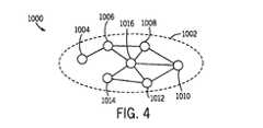
A.単一ネットワークトポロジ
図4は、単一のネットワークトポロジを有するファブリック1000の実施の形態を示す。示されるように、ファブリック1000は単一の論理ネットワーク1002を含む。ネットワーク1002は、イーサネット、WiFi、802.15.4、電力線網、および/またはIPv6プロトコルにおける他の好適なネットワークタイプを含み得る。実際、ネットワーク1002がWiFiまたはイーサネットネットワークを含むいくつかの実施の形態では、ネットワーク1002は、リンク層において橋渡しされる複数のWiFiおよび/またはイーサネットセグメントにわたってもよい。A. Single Network Topology FIG. 4 shows an embodiment of
ネットワーク1002は、1つ以上のノード1004、1006、1008、1010、1012、1014および1016を含み、それらは総称的に1004〜1016と称される。示されるネットワーク1002は7つのノードを含むが、ネットワーク1002のある実施の形態は、ネットワーク1002を用いて相互接続される1つ以上のノードを含んでもよい。さらに、ネットワーク1002がWiFiネットワークである場合には、ノード1004〜1016の各々は、ノード1016(たとえばWiFiルータ)を用いて相互接続されてもよく、および/またはWiFi Direct(つまりWiFi P2P)を用いて他のノードと
対にされてもよい。
B.星形ネットワークトポロジ
図5は、星形ネットワークトポロジを有するファブリック1018としての、ファブリック1000の代替的実施の形態を示す。ファブリック1018は、2つの周辺ネットワーク1022と1024とを併せるハブネットワーク1020を含む。ハブネットワーク1020は、WiFi/イーサネットネットワークまたは電力線網などのような、住宅ネットワークを含んでもよい。周辺ネットワーク1022および1024は、ハブネットワーク1020とは異なるタイプの異なるさらなるネットワーク接続タイプであってもよい。たとえば、ある実施の形態では、ハブネットワーク1020はWiFi/イーサネットネットワークであってもよく、周辺ネットワーク1022は802.15.4ネットワークを含んでもよく
、周辺ネットワーク1024は電力線網、ZigBeeRネットワーク, ISA100.11aネットワー
ク, WirelessHARTネットワーク,またはMiWiTMネットワークを含んでもよい。さらに、フ
ァブリック1018の示される実施の形態は3つのネットワークを含むが、ファブリック1018のある実施の形態は、2つ、3つ、4つ、5つまたはそれより多いネットワークなどのような任意の数のネットワークを含んでもよい。実際、ファブリック1018のある実施の形態は、同じタイプの複数の周辺ネットワークを含む。B. Star Network Topology FIG. 5 shows an alternative embodiment of
示されるファブリック1018は14個のノードを含み、各々は個々に参照番号1024〜1052によりそれぞれ示されるが、ファブリック1018は任意の数のノードを含んでもよいことが理解されるべきである。各ネットワーク1020、1022、または1024内における通信は、直接装置間において、および/またはWiFi/イーサネットネットワークにおけるノード1042のようなアクセスポイントを介して生じてもよい。周辺ネットワーク1022と1024との間の通信は、ネットワーク間ルーティングノードを用いて、ハブネットワーク1020を通過してもよい。たとえば、示される実施の形態では、ノード1034および1036は、第1のネットワーク接続タイプ(たとえば802.15.4)を用いて周辺ネットワーク1022に接続され、第2のネットワーク接続タイプ(たとえばWiFi)を用いてハブネットワーク1020に接続され、一方、ノード1044は、第2のネットワーク接続タイプを用いてハブネットワーク1020に接続され、第3のネットワーク接続タイプ(たとえば電力線)を用いて周辺ネットワーク1024に接続される。たとえば、ノード1026からノード1052に送信されるメッセージは、ノード1052への通過途中において、ノード1028、1030、1032、1036、1042、1044、1048および1050を通過してもよい。 It should be understood that the
C.重なったネットワークトポロジ
図6は、重なったネットワークトポロジを有するファブリック1054としての、ファブリック1000の代替的実施の形態を示す。ファブリック1054はネットワーク1056および1058を含む。示されるように、ノード1062、1064、1066、1068、1070および1072の各々はネットワークの各々に接続されてもよい。他の実施の形態では、ノード1072は、エンドポイントではなく、イーサネット/WiFiネットワークに対するアクセスポイントを含んでもよく、どちらがイーサネット/WiFiネットワークでなくても、ネットワーク1056またはネットワーク1058のいずれか上になくてもよい。したがって、ノード1062からノード1068への通信は、ネットワーク1056、ネットワーク1058またはそれらの何らかの組合せを通過してもよい。示される実施の形態では、各ノードは、任意の所望のネットワークを用いて、任意のネットワークを介して任意の他のノードと通信することができる。したがって、図5の星形ネットワークトポロジとは異なり、重なったネットワークトポロジは、ネットワーク間ルーティングを用いることなく、任意のネットワークを介して直接ノード間において通信してもよい。C. Overlapping Network Topology FIG. 6 shows an alternative embodiment of
D.サービスに対するファブリックネットワーク接続
住宅内における装置間の通信に加えて、ファブリック(たとえばファブリック1000)は、ファブリックにおける他の装置の物理的近くに、またはそのような装置から物理的に遠くに位置してもよいサービスを含んでもよい。ファブリックは、これらのサービスに、1つ以上のサービスエンドポイントを介して接続する。図7は、ファブリック1076、1078および1080と通信するサービス1074の実施の形態を示す。サービス1074は、ファブリック1076、1078、および/または1080内において装置によって用いられてもよいさまざまなサービスを含んでもよい。たとえば、ある実施の形態では、サービス1074は、装置に対して時刻を供給する時刻サービス、さまざまな気象データ(たとえば外部温度、日没、風情報、天気予報など)を提供する気象サービス、各装置をpingするエコーサービス、データ管理サービス、装置管理サービス、および/
または他の好適なサービスであってもよい。示されるように、サービス1074は、関係のあるデータを記憶/にアクセスし、ファブリック1076のようなファブリックにおいてサービスエンドポイント1084を介して1つ以上のエンドポイント1086に情報を渡すサーバ1082(たとえばウェブサーバ)を含んでもよい。示される実施の形態は単一のサーバ1082を伴う3つのファブリックを含むに過ぎないが、サービス1074は、任意の数のファブリックに接続してもよく、サーバ1082に加えてサーバを含んでもよく、および/またはさらなるサービスに対する接続を含んでもよいことが理解されるべきである。D. Fabric network connection to services In addition to communication between devices in a home, the fabric (eg Fabric 1000) may be physically close to or physically far from other devices in the fabric. It may include good service. The fabric connects to these services through one or more service endpoints. FIG. 7 shows an embodiment of
Alternatively, it may be another suitable service. As shown,
ある実施の形態では、サービス1074は、さらに、電話、ケーブルおよび/またはコンピュータのような消費者装置1088に接続してもよい。消費者装置1088は、ファブリック1076のようなファブリック、インターネット接続、および/または何らかの他の好適な接続方法を介してサービス1074に接続するよう用いられてもよい。消費者装置1088は、ファブリックにおける1つ以上のエンドポイント(たとえば電子装置)から、直接そのファブリックを介してか、またはサービス1074を介してデータにアクセスするよう用いられてもよい。換言すれば、サービス1074を用いて、消費者装置1088は、ファブリックにおける装置に対して、そのファブリックから遠隔でアクセスするか、またはそのような装置を管理するよう用いられてもよい。 In certain embodiments, the
E.ファブリックにおける装置間における通信
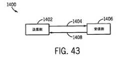
上で論じたように、各電子装置またはノードは、ファブリックトポロジおよびネットワーク接続タイプによって、ファブリック内の任意の他のノードと、直接的または間接的に通信してもよい。加えて、いくつかの装置(たとえば遠隔装置)は、サービスを介して通信して、ファブリックにおける他の装置と通信してもよい。図8は、2つの装置1092と1094との間における通信1090の実施の形態を示す。通信1090は、上に記載されるように、1つ以上のネットワークに、直接的に、またはさらなる装置および/もしくはサービスを介して間接的にわたってもよい。加えて、通信1090は、1つ以上のトランスポートプロトコルを用いて、IPv6のような適切な通信プロトコルを介して生じてもよい。たとえば、いくつかの実施の形態では、通信1090は、伝送制御プロトコル(TCP)および/またはユーザ・データグラム・プロトコル(UDP)を用いることを含んでもよい。ある実施の形態では、装置1092は、無接続プロトコル(たとえばUDP)を用いて、第1の信号1096を装置1094に送信してもよい。ある実施の形態では、装置1092は接続指向型プロトコル(たとえばTCP)を用いて装置1094と通信してもよい。示される通信1090は双方向通信として示されるが、いくつかの実施の形態では、通信1090は一方向同報通信であってもよい。E. Communication between devices in the fabric As discussed above, each electronic device or node may communicate directly or indirectly with any other node in the fabric, depending on the fabric topology and network connection type. In addition, some devices (eg, remote devices) may communicate over the service to communicate with other devices in the fabric. FIG. 8 shows an embodiment of
i.固有のローカルアドレス
上で論じられたように、ファブリック内において送信されノードによって受信されるデータは、その通信に関する所望の目標によって、そのノードを通して他のノードに方向変更されるかまたは渡されてもよい。いくつかの実施の形態では、データの送信はすべての装置に対して同報通信されるよう意図されてもよい。そのような実施の形態では、データは、データが先へと他のノードに渡されるべきであるかを判断するようさらなる処理なしに再送信されてもよい。しかしながら、いくつかのデータは具体的なエンドポイントに向けられてもよい。アドレス指定されたメッセージが所望のエンドポイントに送信されることを可能にするために、ノードは識別情報を割当てられてもよい。i. Unique Local Address As discussed above, data transmitted within the fabric and received by a node may be redirected or passed through that node to other nodes, depending on the desired goals for that communication. Good. In some embodiments, the transmission of data may be intended to be broadcast to all devices. In such an embodiment, the data may be retransmitted without further processing to determine if the data should be passed to another node first. However, some data may be directed to specific endpoints. Nodes may be assigned identification information to allow addressed messages to be sent to the desired endpoint.
各ノードは、1つが各ネットワークインターフェイスに割当てられるリンクローカルアドレス(LLA)の組を割当てられてもよい。これらのLLAを用いて、同じネットワーク上の他の装置と通信してもよい。加えて、LLAは、IPv6近隣探索プロトコルのようなさまざまな通信手順に対して用いられてもよい。LLAに加えて、各ノードは固有の
ローカルアドレス(ULA)を割当てられてもよい。Each node may be assigned a set of link-local addresses (LLAs), one assigned to each network interface. These LLAs may be used to communicate with other devices on the same network. In addition, LLA may be used for various communication procedures such as IPv6 Neighbor Discovery Protocol. In addition to LLA, each node may be assigned a unique local address (ULA).
図9は、ファブリックにおける各ノードをアドレス指定するよう用いられてもよい固有のローカルアドレス(ULA)1098の実施の形態を示す。ある実施の形態では、ULA1098は、グローバルID1100とサブネットID1102とインターフェイスID1104とに分割される128ビットを含むIPv6アドレスフォーマット(書式)としてフォーマット(書式設定)されてもよい。グローバルID1100は40ビットを含み、サブネットID1102は16ビットを含む。グローバルID1100およびサブネットID1102は、ともになって、ファブリックに対するファブリックID1103を形成する。 FIG. 9 shows an embodiment of a unique local address (ULA) 1098 that may be used to address each node in the fabric. In certain embodiments, ULA1098 may be formatted as an IPv6 address format containing 128 bits divided into
ファブリックID1103は、ファブリックを識別するよう用いられる一意の64ビットの識別子である。ファブリックID1103は、擬似乱数アルゴリズムを用いて、関連づけられるファブリックの形成で生成されてもよい。たとえば、擬似乱数アルゴリズムは、1)現在の時刻を64ビットのNTPフォーマットで得てもよく、2)装置に対するインターフェイスID1104を得てもよく、3)時刻をインターフェイスID1104と連結してキーを形成してもよく、4)SHA−1ダイジェストをそのキーの上で計算して、結果として160ビットをもたらしてもよく、5)最下位の40ビットをグローバルID1100として用いてもよく、および6)ULAを連結し、最下位ビットを1にセットして、ファブリックID1103を形成してもよい。ある実施の形態では、一旦ファブリックID1103がファブリックとともに形成されると、ファブリックID1103はそのファブリックが解消されるまで残る。 Fabric ID 1103 is a unique 64-bit identifier used to identify the fabric. Fabric ID 1103 may be generated in the formation of the associated fabric using a pseudo-random algorithm. For example, a pseudo-random algorithm may 1) obtain the current time in 64-bit NTP format, 2) obtain
グローバルID1100は、ノードが属するファブリックを識別する。サブネットID1102はファブリック内の論理ネットワークを識別する。サブネットIDF3は、ファブリックに対する各新たな論理ネットワークの追加で、1で単調に開始することを割当てられてもよい。たとえば、WiFiネットワークは0x01の16進値で識別されてもよく、後で接続される802.15.4ネットワークは、0x02の16進値で識別されてもよく、ファブリックに対する各新たなネットワークの接続で、増分的に継続し続けてもよい。
最後に、ULA1098は、64ビットを含むインターフェイスID1104を含んでもよい。インターフェイスID1104は、IEEE EUI−64規格に従って、グローバルに一意の64ビット識別子を用いて割当てられてもよい。たとえば、IEEE802ネットワークインターフェイスを伴う装置は、装置の「一次インターフェイス」のためにバーンド・インのMACアドレスを用いて、インターフェイスID1104を導出してもよい。いくつかの実施の形態では、どのインターフェイスが一次インターフェイスであるかの指定は任意に判断されてもよい。他の実施の形態では、あるインターフェイスタイプ(たとえばWiFi)が、存在する場合には、一次インターフェイスとしてみなされてもよい。装置の一次インターフェイスに対するMACアドレスが48ビットであり、64ビットでない場合には、48ビットのMACアドレスは、カプセル化(たとえば組織的に一意の識別子カプセル化)を介して、EUI−64値に変換されてもよい。消費者装置(たとえば電話またはコンピュータ)においては、インターフェイスID1104は消費者装置のローカルオペレーティングシステムによって割当てられてもよい。 Finally, ULA1098 may include
ii.論理ネットワーク間において送信をルーティングする
星形ネットワークトポロジに関して上で論じられたように、ネットワーク間ルーティングは、論理ネットワーク間を渡る2つの装置間における通信において生じてもよい。いくつかの実施の形態では、ネットワーク間ルーティングはサブネットID1102に基づく。各ネットワーク間接続ノード(たとえば図5のノード1034)は、ハブネットワーク1020上のルーティングノードのリスト(たとえば図5のノードB14)、およびそれ
らのそれぞれの取付けられた周辺ネットワーク(たとえば図5の周辺ネットワーク1024)を維持してもよい。ルーティングノードそれ自体以外のノードにアドレス指定されたパケットが到着すると、宛先アドレス(たとえば図5のノード1052に対するアドレス)がネットワークプレフィックスのリストと比較され、所望のネットワーク(たとえば周辺ネットワーク1024)に取付けられるルーティングノード(たとえばノード1044)が選択される。パケットは、次いで、その選択されたルーティングノードに転送される。複数のノード(たとえば1034および1036)が同じ周辺ネットワークに取付けられる場合には、ルーティングノードは交互する態様で選択される。ii. Routing Transmissions Between Logical Networks As discussed above for star network topologies, internetwork routing may occur in communication between two devices across a logical network. In some embodiments, inter-network routing is based on subnet ID 1102. Each inter-network connection node (eg,
加えて、ネットワーク間ルーティングノードは、近隣探索プロトコル(NDP)ルータ情報提供メッセージをハブネットワーク上において定期的に送信して、消費者装置に対してハブネットワークの存在についての注意を喚起し、消費者装置がサブネットプレフィックスを得ることができるようにしてもよい。ルータ情報提供は、ファブリックにおけるルーティング情報において支援するよう1つ以上のルート情報オプションを含んでもよい。たとえば、これらのルート情報オプションは、消費者装置に対して、周辺ネットワークの存在、およびどのようにしてパケットを周辺装置にルーティングするかを知らせてもよい。 In addition, the inter-network routing node periodically sends Neighbor Discovery Protocol (NDP) router information provision messages over the hub network to alert consumer equipment about the existence of the hub network and consumers. The device may be able to obtain a subnet prefix. The router information provision may include one or more route information options to assist in the routing information in the fabric. For example, these route information options may inform the consumer device of the existence of a peripheral network and how packets are routed to the peripheral device.
ルート情報オプションに加えて、またはそれらに代わって、ルーティングノードは、プロキシとして振舞って、図10に示されるプロセス1105のように、消費者装置と周辺ネットワークにおける装置との間において通信を与えてもよい。示されるように、プロセス1105は、各周辺ネットワーク装置に対するハブネットワーク上の仮想アドレスの割当が、その周辺ネットワーク上における装置についてサブネットID1102をインターフェイスID1104と組合せることによって行なうことを含む(ブロック1106)。仮想アドレスを用いてプロキシ化するために、ルーティングノードは、ファブリックにおける、そのインターフェイスの1つを介して直接到達可能なすべての周辺ノードのリストを含む(ブロック1108)。ルーティングノードは、ハブネットワーク上において、周辺ノードのリンクアドレスを、その仮想アドレスを用いて要求する近隣請求メッセージに対するリスニングを行なう(ブロック1110)。そのようなメッセージを受信すると、ルーティングノードは、ある時間期間のあと、その仮想アドレスをそれのハブインターフェイスに割当てることを試みる(ブロック1112)。割当の一部として、ルーティングノードは、2つ以上のルーティングノードによる仮想アドレスのプロキシ化を阻止するように、二重アドレス検出を実行する。割当のあと、ルーティングノードは、近隣請求メッセージに応答し、パケットを受信する(ブロック1114)。パケットを受信すると、ルーティングノードは、宛先アドレスを周辺ノードの実アドレスに書換え(ブロック1116)、メッセージを適切なインターフェイスに転送する(ブロック1118)。 In addition to or on behalf of the route information options, the routing node may act as a proxy to provide communication between the consumer device and the device in the peripheral network, as in
iii.消費者装置のファブリックへの接続
ファブリックに加わるために、消費者装置は、その消費者装置が加わりたいファブリックに既にあるノードのアドレスを探索してもよい。加えて、消費者装置が、ある延長された時間期間の間、ファブリックから切断されている場合、ファブリックトポロジ/レイアウトが変更している場合には、ネットワーク上においてノードを再探索する必要があってもよい。探索/再探索において支援するために、ハブネットワーク上のファブリック装置は、mDNSを介して、ファブリックの存在を情報提供しアドレスを消費者装置に与えるドメイン名システム−サービス探索(DNS−SD)を公開してもよい。iii. Connecting a Consumer Device to the Fabric To join the fabric, the consumer device may search for the address of a node already in the fabric to which the consumer device wants to join. In addition, if the consumer device has been disconnected from the fabric for an extended period of time, or if the fabric topology / layout has changed, it may be necessary to re-discover the nodes on the network. May be good. To assist in the search / re-search, the fabric device on the hub network publishes the domain name system-service search (DNS-SD) that informs the existence of the fabric and gives the address to the consumer device via mDNS. You may.
III.ファブリックにおいて送信されるデータ
ファブリックの形成およびノードに対するアドレス形成のあと、データがファブリックを通して送信されてもよい。ファブリックを通して渡されるデータは、すべてのメッセージに共通の、および/またはそのファブリックにおいて特定のタイプの会話に共通のフォ
ーマットで構成されてもよい。いくつかの実施の形態では、メッセージフォーマットは、以下に論じられるTLV直列化フォーマットを用いて、JavaScriptオブジェクト表記法(JSON)に対する1対1マッピングを可能にしてもよい。加えて、以下のデータフレームは特定のサイズを含むとして記載されるが、それらのデータフレームにおけるデータフィールドの長さは他の好適なビット長に変動されてもよい旨が注記されるべきである。III. Data transmitted in the fabric After forming the fabric and addressing the nodes, data may be transmitted through the fabric. The data passed through the fabric may be configured in a format that is common to all messages and / or to certain types of conversations in that fabric. In some embodiments, the message format may allow one-to-one mapping to JavaScript object notation (JSON) using the TLV serialization format discussed below. In addition, although the following data frames are described as containing certain sizes, it should be noted that the length of the data fields in those data frames may vary to other suitable bit lengths. ..
以下に論じられる以下のデータフレーム、プロファイルおよび/またはフォーマットの各々は、メッセージの送信前および/または送信後にメモリ(たとえば装置10のメモリ)に記憶されてもよいことが理解されるべきである。換言すれば、データフレーム、プロファイルおよびフォーマットは一般的にはデータの送信として論じられるが、それらは、さらに、データフレーム、プロファイル、および/またはフォーマットの送信前、送信中および/または送信後に(たとえばバッファに)物理的に記憶されてもよい。さらに、以下のデータフレーム、プロファイル、スキーマ、および/またはフォーマットは、電子装置がデータフレーム、プロファイル、スキーマおよび/またはフォーマットにアクセスすることを可能にする非一時的なコンピュータ読取可能媒体に記憶されてもよい。たとえば、データフレーム、プロファイル、スキーマおよび/またはフォーマットをフォーマットするための命令は、装置10に対するメモリ、他の装置のメモリ、ポータブルメモリ装置(たとえばコンパクトディスク、フラッシュドライブなど)、またはデータフレーム、プロファイル、スキーマおよび/もしくはフォーマットを記憶するための他の好適な物理的装置などのような、任意の好適なコンピュータ読取可能媒体に記憶されてもよい。 It should be understood that each of the following data frames, profiles and / or formats discussed below may be stored in memory (eg, memory of device 10) before and / or after transmission of the message. In other words, data frames, profiles and formats are generally discussed as data transmissions, but they are also further discussed before, during and / or after transmission of data frames, profiles and / or formats (eg, for example). It may be physically stored (in the buffer). In addition, the following data frames, profiles, schemas, and / or formats are stored on non-temporary computer-readable media that allow electronic devices to access the data frames, profiles, schemas, and / or formats. May be good. For example, instructions for formatting data frames, profiles, schemas and / or formats can be memory for
A.セキュリティ
転送されるよう意図されるデータとともに、ファブリックは、データを、暗号化、メッセージ完全性チェック、デジタル署名などのような、さらなるセキュリティ手段とともに転送してもよい。ある実施の形態では、装置に対してサポートされるセキュリティのレベルは、装置の物理的セキュリティおよび/または装置の能力に従って変動してもよい。ある実施の形態では、ファブリックにおいてノード間において送信されるメッセージは、カウンタモード(AES−CTR)において128ビットのキーで動作する高度暗号化標準(AES)ブロック暗号を用いて暗号化されてもよい。以下に論じられるように、各メッセージは32ビットのメッセージidを含む。このメッセージidは、送信側ノードidと組合されて、AES−CTRアルゴリズムに対するノンスを形成してもよい。32ビットカウンタは、40億個のメッセージが暗号化され各ノードによって送信されたのちに、新たなキーが交渉されることを可能にする。A. Security Along with the data intended to be transferred, the fabric may transfer the data with additional security measures such as encryption, message integrity checking, digital signatures, and so on. In certain embodiments, the level of security supported for the device may vary according to the physical security of the device and / or the capabilities of the device. In certain embodiments, messages transmitted between nodes in the fabric may be encrypted using an Advanced Encryption Standard (AES) block cipher that operates with a 128-bit key in counter mode (AES-CTR). .. Each message contains a 32-bit message id, as discussed below. This message id may be combined with the sending node id to form a nonce to the AES-CTR algorithm. The 32-bit counter allows 4 billion messages to be encrypted and sent by each node before a new key is negotiated.
いくつかの実施の形態では、ファブリックは、各暗号化されたメッセージに含まれてもよい、HMAC−SHA−1のような、メッセージ認証コードを用いて、メッセージ完全性を保証してもよい。いくつかの実施の形態では、メッセージ認証コードは、暗号化キーと1対1で対にされる160ビットのメッセージ完全性キーを用いて生成されてもよい。加えて、各ノードは、入来メッセージのメッセージidを、ノード単位で維持される最近受信されたidのリストと照合して、メッセージの再生を阻止してもよい。 In some embodiments, the fabric may be included in each encrypted message and may use a message authentication code, such as HMAC-SHA-1, to guarantee message integrity. In some embodiments, the message authentication code may be generated using a 160-bit message integrity key that is paired one-to-one with the encryption key. In addition, each node may block the playback of the message by matching the message id of the incoming message with the list of recently received ids maintained on a node-by-node basis.
B.タグ‐長さ‐値(TLV)フォーマット化
電力消費を低減するためには、ファブリックにより送信されるデータの少なくとも一部をそのようにコンパクトに送信する一方で、データコンテナが、データの直列化内において理解されるデータの次の位置にスキップすることによって認識または理解されないデータをスキップすることに対応するデータを柔軟性を持って表わすことができることが望ましい。ある実施の形態では、タグ‐長さ‐値(TLV)フォーマット化を用いて、データをコンパクトに、かつ柔軟性を持ってエンコード/デコードしてもよい。送信されるデータの少なくとも一部をTLVで記憶することによって、データは、以下において表7を参照して論じられるように、低エンコード/デコードおよびメモリオーバヘッドで、コンパ
クトに、かつ柔軟性を持って記憶/送信されてもよい。ある実施の形態では、TLVは、あるデータに対しては、柔軟性のある、拡張可能なデータとして用いられてもよいが、拡張可能でないデータの他の部分は、理解される標準プロトコルデータ単位(PDU)で記憶および送信されてもよい。B. Tag-Length-Value (TLV) Formatting In order to reduce power consumption, at least part of the data transmitted by the fabric is transmitted so compactly, while the data container is within the data serialization It is desirable to be able to flexibly represent the data corresponding to skipping the data that is not recognized or understood by skipping to the next position of the data that is understood in. In certain embodiments, tag-length-value (TLV) formatting may be used to encode / decode data in a compact and flexible manner. By storing at least part of the transmitted data in TLV, the data is compact and flexible with low encoding / decoding and memory overhead, as discussed below with reference to Table 7. It may be stored / transmitted. In some embodiments, the TLV may be used as flexible, extensible data for some data, but other parts of the non-extensible data are understood standard protocol data units. It may be stored and transmitted in (PDU).
TLVフォーマットでフォーマットされるデータは、プリミティブタイプおよびコンテナタイプなどのような、さまざまなタイプのTLV要素としてエンコードされてもよい。プリミティブタイプは、整数または文字列のような、あるフォーマットにおけるデータ値を含む。たとえば、TLVフォーマットは、1、2、3、4または8バイトの符号有り/符号無し整数、UTF−8文字列、バイト文字列、単精度/倍精度浮動数(たとえばIEEE754−1985フォーマット)、ブーリアン、ヌル、および他の好適なデータフォーマットタイプをエンコードしてもよい。コンテナタイプは要素の集まりを含み、それらは、次いで、コンテナタイプまたはプリミティブタイプとして下位分類される。コンテナタイプは、ディクショナリ、アレイ、パス、またはメンバーとして既知の、TLV要素をグループ化するための他の好適なタイプのような、さまざまなカテゴリに分類されてもよい。ディクショナリは、そのディクショナリ内において明確な定義および一意のタグを各々が有するメンバーの集まりである。アレイは、暗示される定義を伴うかまたは明確な定義を伴わない、順序づけられたメンバーの集まりである。パスは、TLV要素のツリーをどのように横断するかを記載した、順序づけられたメンバーの集まりである。 Data formatted in TLV format may be encoded as various types of TLV elements, such as primitive types and container types. Primitive types include data values in certain formats, such as integers or strings. For example, the TLV format is 1, 2, 3, 4 or 8-byte signed / unsigned integers, UTF-8 strings, byte strings, single / double precision floats (eg IEEE754-1985 format), Boolean. , Null, and other suitable data format types may be encoded. A container type contains a collection of elements, which are then subclassified as a container type or a primitive type. Container types may fall into various categories, such as dictionary, array, path, or other suitable type for grouping TLV elements known as members. A dictionary is a collection of members, each with a well-defined definition and a unique tag within that dictionary. An array is an ordered collection of members with implied or unexplained definitions. A path is an ordered collection of members that describes how to traverse a tree of TLV elements.
図11に示されるように、TLVパケット1120の実施の形態は3つのデータフィールド:タグフィールド1122と長さフィールド1124と値フィールド1126とを含む。示されるフィールド1122、1124および1126はサイズがおおよそ等価として示されているが、各フィールドのサイズは可変であってもよく、互いに対してサイズが変動してもよい。他の実施の形態では、TLVパケット1120は、さらに、タグフィールド1122の前に制御バイトを含んでもよい。 As shown in FIG. 11, embodiments of
制御バイトを有する実施の形態では、制御バイトは要素タイプフィールドとタグ制御フィールドとに下位分割されてもよい。いくつかの実施の形態では、要素タイプフィールドは制御バイトの下位5ビットを含み、タグ制御フィールドは上位3ビットを占める。要素タイプフィールドは、TLV要素のタイプと、どのように長さフィールド1124および値フィールド1126がエンコードされるかを示す。ある実施の形態では、要素タイプフィールドは、さらに、TLVについてブーリアン値および/またはヌル値をエンコードする。たとえば、要素タイプフィールドの列挙の実施例が以下において表1に与えられる。 In embodiments with control bytes, the control bytes may be subdivided into element type fields and tag control fields. In some embodiments, the element type field contains the lower 5 bits of the control byte and the tag control field occupies the upper 3 bits. The element type field indicates the type of TLV element and how the

タグ制御フィールドは、(ゼロ長タグを含む)TLV要素に割当てられるタグフィールド1122におけるタグのある形式を示す。タグ制御フィールド値の例が以下に表2において与えられる。The tag control field indicates the tagged format in the
換言すれば、制御バイトを有する実施の形態では、制御バイトはタグの長さを示してもよい。In other words, in embodiments with control bytes, the control bytes may indicate the length of the tag.
ある実施の形態では、タグフィールド1122は、8ビット、16ビット、32ビット、または64ビットなどのような、0〜8バイトを含んでもよい。いくつかの実施の形態では、タグフィールドのタグはプロファイル特定タグまたは文脈特定タグとして分類されてもよい。プロファイル特定タグは、以下に論じられるように、ベンダId、プロファイルId、および/またはタグ番号を用いて、要素をグローバルに識別する。文脈特定タグは、含むディクショナリ要素の文脈内でTLV要素を識別し、1バイトのタグ番号を含んでもよい。文脈特定タグはそれらのコンテナの文脈において定義されるので、1つの文脈特定タグは、異なるコンテナ内に含まれるときには、異なる解釈を有し得る。いくつかの実施の形態では、文脈は、さらに、ネスト化されたコンテナから導出されてもよい。 In certain embodiments, the
制御バイトを有する実施の形態では、タグ長はタグ制御フィールドにおいてエンコードされ、タグフィールド1122は可能な3つのフィールド:ベンダIdフィールド、プロファイルIdフィールド、およびタグ番号フィールドを含む。十分に適格とされる形式では、エンコードされたタグフィールド1122はすべての3つのフィールドを含み、タグ番号フィールドは、タグ制御フィールドによって決められる16ビットまたは32ビットを含む。暗黙的形式では、タグはタグ番号のみを含み、ベンダIdおよびプロファイル番号はTLV要素のプロトコル文脈から推測される。コアプロファイル形式は、以下に論じられるように、プロファイル特定タグを含む。文脈特定タグは、タグ番号を搬送する1つのバイトとしてエンコードされる。匿名要素はゼロ長タグフィールド1122を有する。 In embodiments with control bytes, the tag length is encoded in the tag control field, and
制御バイトを伴わないいくつかの実施の形態では、2つのビットがタグフィールド1122の長さを含んでもよく、2つのビットが長さフィールド1124の長さを含んでもよく、4つのビットが値フィールド1126に記憶される情報のタイプを示してもよい。タグフィールドに対する上位8ビットに対する考えられ得るエンコーディングの一例が以下に表3において示される。 In some embodiments without control bytes, two bits may contain the length of the
表3に示されるように、タグフィールド1122の上位8ビットを用いて、タグフィールド1122、長さフィールド1124および値フィールド1126についての情報をエンコードしてもよく、タグフィールド1122を用いてタグフィールド1122および長さフィールド1124に対して長さを判断してもよい。タグフィールド1122における残りのビットは、ユーザ配分および/またはユーザ割当てされるタグ値に対して利用可能にされてもよい。As shown in Table 3, the upper 8 bits of
長さフィールド1124は、表3に示されるようにタグフィールド1122によって、
または表2に示されるように要素フィールドによって示されるように、8ビット、16ビット、32ビットまたは64ビットを含んでもよい。さらに、長さフィールド1124は、値フィールド1126においてエンコードされるものの長さを表わす、符号無し整数を含んでもよい。ある実施の形態では、長さは、TLV要素を送信する装置によって選択されてもよい。値フィールド1126は、デコードされるべきペイロードデータを含むが、値フィールド1126の解釈はタグ長フィールドおよび/または制御バイトに依存してもよい。たとえば、8ビットタグを含む制御バイトを伴わないTLVパケットが、以下において説明のために表4に示される。The
Alternatively, it may include 8 bits, 16 bits, 32 bits or 64 bits as shown by the element fields as shown in Table 2. In addition, the
表4に示されるように、1行目は、タグフィールド1122および長さフィールド1124が各々8ビットの長さを有することを示す。加えて、タグフィールド1122は、タグタイプが1行目に対するものであり、コンテナであることを示す(たとえばTLVパケット)。第2行から第6行に対するタグフィールド1124は、TLVパケットにおける各エントリが、各々8ビットからなるタグフィールド1122と長さフィールド1124とを有することを示す。加えて、タグフィールド1124は、TLVパケットにおける各エントリが、32ビットの浮動小数点を含む値フィールド1126を有することを示す。値フィールド1126における各エントリは、対応するタグフィールド1122および長さフィールド1124情報を用いてデコードされてもよい浮動数に対応する。この例に示されるように、値フィールド1126における各エントリは華氏における温度に対応する。理解できるように、上記のようにデータをTLVパケットに格納することによって、データは、ファブリックにおいて異なる装置によって用いられ得るように、さまざまな長さおよび情報に対して柔軟性のあるままでコンパクトに転送され得る。さらに、ある実施の形態では、マルチバイト整数フィールドは、リトルエンディアン順序またはビッグエンディアン順序で送信されてもよい。As shown in Table 4, the first row shows that the
送信側/受信側装置フォーマット(たとえばJSON)によって用いられてもよい順序プロトコル(たとえばリトルエンディアン)を用いてTLVパケットを送信することによって、ノード間で転送されるデータは、ノードの少なくとも1つによって用いられる順序プロトコル(たとえばリトルエンディアン)で送信されてもよい。たとえば、1つ以上のノードがARMまたはix86プロセッサを含む場合には、ノード間の伝送を、リトルエンディアンバイト順序づけを用いて伝送することにより、バイト再順序づけの使用を低減してもよい。バイト再順序づけを含むことを低減することによって、TLVフォーマットは、伝送の両端でバイト再順序づけを用いる伝送よりも少ない電力を用いて装置が通信することを可能にする。さらに、TLVフォーマット化は、JSON+拡張可能マークアップ言語(XML)のような、他のデータ格納技術間における1対1翻訳を与えるよう指定されてもよい。一例として、TLVフォーマットを用いて以下のXMLプロパティリスト
を表現してもよい。By transmitting TLV packets using an ordinal protocol (eg little endian) that may be used by the sender / receiver device format (eg JSON), the data transferred between the nodes is by at least one of the nodes. It may be transmitted in the order protocol used (eg little endian). For example, if one or more nodes include an ARM or ix86 processor, the use of byte reordering may be reduced by transmitting between the nodes using little endian byte ordering. By reducing the inclusion of byte reordering, the TLV format allows the device to communicate at both ends of the transmission with less power than transmission using byte reordering. In addition, TLV formatting may be specified to provide a one-to-one translation between other data storage techniques, such as JSON + Extensible Markup Language (XML). As an example, the following XML property list may be expressed using the TLV format.
一例として、上記のプロパティリストは、以下の表5に従って(制御バイトなしで)上記のTLVフォーマットのタグにおいて表現されてもよい。As an example, the above property list may be represented in the above TLV format tags (without control bytes) according to Table 5 below.
同様に、表6は、例示のXMLプロパティリストに対するリテラルタグ、長さ、および値表現の一例を示す。Similarly, Table 6 shows an example of literal tags, lengths, and value representations for an exemplary XML property list.
TLVフォーマットは、さらにXMLとも列挙されてもよいプロパティの参照を可能にするが、より小さい格納サイズとでも同様である。たとえば、表7は、XMLプロパティリスト、対応するバイナリプロパティリスト、およびTLVフォーマットのデータサイズの比較を示す。The TLV format also allows references to properties that may also be listed as XML, as well as smaller storage sizes. For example, Table 7 shows a comparison of XML property lists, corresponding binary property lists, and TLV format data sizes.
データを転送するのに用いられるデータの量を低減することによって、TLVフォーマットは、ファブリック1000が、限られた電力のために短いデューティサイクルを有する装置(たとえばバッテリ供給される装置)に対してデータを転送することおよび/またはそのような装置からデータを転送することを可能にする。換言すれば、TLVフォーマットは、送信されるべきデータのコンパクト性を増大させながら送信の柔軟性を可能にする。By reducing the amount of data used to transfer the data, the TLV format allows the
C.一般的なメッセージプロトコル
さまざまなサイズを有する特定のエントリを送信することに加えて、データは、ファブリック内において、TLVフォーマット化を組込んでもよい一般的なメッセージプロトコルを用いて送信されてもよい。一般的なメッセージプロトコル(GMP)1128の実施の形態が図12に示される。ある実施の形態では、一般的なメッセージプロトコル(GMP)1128は、ファブリック内においてデータを送信するよう用いられてもよい。GMP1128は、データを無接続プロトコル(たとえばUDP)および/または接続指向型プロトコル(たとえばTCP)を介してデータを送信するよう用いられてもよい。したがって、GMP1128は、1つのプロトコルにおいて用いられる情報に柔軟に対応する一方で、他のプロトコルが用いられるときにはそのような情報を無視してもよい。さらに、GMP1226は、ある特定の送信においては用いられないフィールドの省略を可能にしてもよい。1つ以上のGMP1226転送から省略されてもよいデータは、一般的には、データ単位の周辺の曖昧な境界を用いて示される。いくつかの実施の形態では、複数バイト整数フィールドをリトルエンディアン順序またはビッグエンディアン順序で送信してもよい。C. Common Message Protocols In addition to sending specific entries of various sizes, data may be sent within the fabric using common message protocols that may incorporate TLV formatting. An embodiment of General Message Protocol (GMP) 1128 is shown in FIG. In certain embodiments, General Message Protocol (GMP) 1128 may be used to transmit data within the fabric. GMP1128 may be used to transmit data via a non-connecting protocol (eg UDP) and / or a connection-oriented protocol (eg TCP). Therefore, while GMP1128 flexibly accommodates information used in one protocol, such information may be ignored when other protocols are used. In addition, GMP1226 may allow the omission of fields that are not used in certain transmissions. Data that may be omitted from one or more GMP1226 transfers are generally indicated with ambiguous boundaries around the data unit. In some embodiments, the multibyte integer field may be transmitted in little endian or big endian order.
i.パケット長
いくつかの実施の形態では、GMP1128はパケット長フィールド1130を含んでもよい。いくつかの実施の形態では、パケット長フィールド1130は2バイトを含む。パケット長フィールド1130におけるある値は、パケット長フィールド1130それ自体を除く、メッセージの全体の長さをバイトで示す符号無し整数に対応する。パケット長フィールド1130は、GMP1128がTCP接続を介して送信されるときに存在してもよいが、GMP1128がUDP接続を介して送信されるときには、メッセージ長は、パケット長フィールド1130を除く基底のUDPパケットのペイロード長と等しくてもよい。i. Packet Length In some embodiments, the
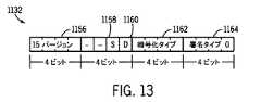
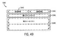
ii.メッセージヘッダ
GMP1128は、さらに、GMP1128がTCPまたはUDP接続を用いて送信されるかどうかに関わらず、メッセージヘッダ1132を含んでもよい。いくつかの実施の形態では、メッセージヘッダ1132は、図13に示されるフォーマットで配される2バイトのデータを含む。図13に示されるように、メッセージヘッダ1132はバージョンフィールド1156を含む。バージョンフィールド1156は、メッセージをエンコードするよう用いられるGMP1128のバージョンに対応する。したがって、GMP1128が更新されると、GMP1128の新たなバージョンが形成されるが、ファブリックにおける各装置は、装置にとって既知のGMP1128の任意のバージョンでデータパケットを受信することができてもよい。バージョンフィールド1156に加えて、メッセージヘッダ1132はSフラグフィールド1158とDフラグ1160とを含んでもよい。Sフラグ1158は、(以下に論じられる)ソースノードIdフィールドが送信されるパケットに含まれるかどうかを示す単一のビットである。同様に、Dフラグ1160は、(以下に論じられる)宛先ノードIdフィールドが送信されるパケットに含まれるかどうかを示す単一のビットである。ii. The message header GMP1128 may further include a
メッセージヘッダ1132は、さらに、暗号化タイプフィールド1162を含む。暗号化タイプフィールド1162は、存在する場合にはどのタイプの暗号化/完全性チェックがメッセージに適用されるかを指定する4つのビットを含む。たとえば、0x0はどのよう
な暗号化またはメッセージ完全性チェックも含まれないことを示してもよく、十進の0x1
はHMAC−SHA−1メッセージ完全性チェックを伴うAES−128−CTR暗号化が含まれることを示してもよい。
May indicate that AES-128-CTR encryption with an HMAC-SHA-1 message integrity check is included.
最後に、メッセージヘッダ1132は、さらに、署名タイプフィールド1164を含む。署名タイプフィールド1164は、もしある場合には、どのタイプのデジタル署名がメッセージに適用されるかを指定する4つのビットを含む。たとえば、0x0はどのようなデ
ジタル署名もメッセージには含まれないことを示してもよく、0x1は、Prime256v1楕円曲
線パラメータを伴う楕円曲線デジタル署名アルゴリズム(ECDSA)がメッセージに含まれることを示してもよい。Finally, the
iii.メッセージId
図12に戻って、GMP1128は、さらに、メッセージIdフィールド1134を含み、それは、送信されるメッセージがTCPまたはUDPを用いて送信されるかどうかに関わらず、メッセージに含まれてもよい。メッセージIdフィールド1134は、メッセージを送信側ノードの視点から一意に識別する符号無し整数値に対応する4つのバイトを含む。いくつかの実施の形態では、ノードは、それらが送信する各メッセージに対して、232個のメッセージに到達したあとは0に戻る、増大するメッセージId1134の値を割当てもよい。iii. Message Id
Returning to FIG. 12, GMP1128 further includes
iv.ソースノードId
ある実施の形態では、GMP1128は、さらに、8つのバイトを含むソースノードIdフィールド1136を含んでもよい。上で論じられたように、ソースノードIdフィールド1136は、メッセージヘッダ1132における単一ビットのSフラグ1158が1にセットされるときにメッセージに存在してもよい。いくつかの実施の形態では、ソースノードIdフィールド1136は、ULA1098のインターフェイスID1104または全ULA1098を含んでもよい。いくつかの実施の形態では、ソースノードIdフィールド1136のバイトは、インデックス値昇順(たとえばEUI[0] 次いでEUI[1] 次いでEUI[2] 次いでEUI[3],など)で送信されてもよい。iv. Source node Id
In certain embodiments, the
v.宛先ノードId
GMP1128は、8つのバイトを含む宛先ノードIdフィールド1138を含んでもよい。宛先ノードIdフィールド1138は、ソースノードIdフィールド1136と同様であるが、宛先ノードIdフィールド1138はメッセージに対する宛先ノードに対応する。宛先ノードIdフィールド1138は、メッセージヘッダ1132における単一ビットのDフラグ1160が1にセットされるときにメッセージに存在してもよい。さらに、ソースノードIdフィールド1136と同様に、いくつかの実施の形態では、宛先ノードIdフィールド1138のバイトはインデックス値昇順(たとえばEUI[0] 次いでEUI[1] 次いでEUI[2] 次いでEUI[3],など)で送信されてもよい。v. Destination node Id
GMP1128 may include a destination
vi.キーId
ある実施の形態では、GMP1128はキーIdフィールド1140を含んでもよい。ある実施の形態では、キーIdフィールド1140は2つのバイトを含む。キーIdフィールド1140はメッセージを暗号化するのに用いられる暗号化/メッセージ完全性キーを識別する符号無し整数値を含む。キーIdフィールド1140の存在は、メッセージヘッダ1132の暗号化タイプフィールド1162の値によって判断されてもよい。たとえば、いくつかの実施の形態では、メッセージヘッダ1132の暗号化タイプフィールド1162に対する値が0x00であるときには、キーIdフィールド1140はメッセージから省略されてもよい。vi. Key Id
In certain embodiments, the
キーIdフィールド1140の実施の形態が図14に提示される。示される実施の形態では、キーIdフィールド1140はキータイプフィールド1166とキー番号フィールド1168とを含む。いくつかの実施の形態では、キータイプフィールド1166は4つのビットを含む。キータイプフィールド1166は、メッセージを暗号化するのに用いられる暗号化/メッセージ完全性のタイプを識別する符号無し整数値に対応する。たとえば、いくつかの実施の形態では、キータイプフィールド1166が0x0である場合には、フ
ァブリックキーはファブリックにおけるノードのすべてまたはほとんどによって共有される。しかしながら、キータイプフィールド1166が0x1である場合には、ファブリック
キーはファブリックにおいてノードの対によって共有される。An embodiment of the
キーIdフィールド1140は、さらに、キー番号フィールド1168を含み、それは、共有されるキーであるかまたはファブリックキーの、利用可能なキーの組からメッセージを暗号化するのに用いられる特定のキーを識別する符号無し整数値に対応する12個のビットを含む。 The
vii.ペイロード長
いくつかの実施の形態では、GMP1128はペイロード長フィールド1142を含んでもよい。ペイロード長フィールド1142は、存在するときには、2つのバイトを含んでもよい。ペイロード長フィールド1142は、アプリケーションペイロードフィールドのサイズをバイトで示す符号無し整数値に対応する。ペイロード長フィールド1142は、以下においてパディングフィールドとの関連において記載される、メッセージパディングを用いるアルゴリズムを用いてメッセージが暗号化されるときに存在してもよい。vii. Payload Length In some embodiments, the
viii.初期化ベクトル
いくつかの実施の形態では、GMP1128は、さらに、初期化ベクトル(IV)フィールド1144を含んでもよい。IVフィールド1144は、存在するときには、可変数のバイトのデータを含む。IVフィールド1144は、メッセージを暗号化するのに用いられる暗号のIV値を含む。IVフィールド1144は、IVを用いるアルゴリズムでメッセージが暗号化されるときに用いられてもよい。IVフィールド1144の長さは、メッセージを暗号化するのに用いられる暗号化のタイプによって導出されてもよい。viii. Initialization Vector In some embodiments, GMP1128 may further include an Initialization Vector (IV)
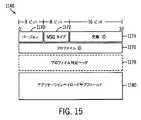
ix.アプリケーションペイロード
GMP1128はアプリケーションペイロードフィールド1146を含む。アプリケーションペイロードフィールド1146は可変数のバイトを含む。アプリケーションペイロードフィールド1146はメッセージにおいて搬送されるアプリケーションデータを含む。アプリケーションペイロードフィールド1146の長さは、存在する場合にはペイロード長フィールド1142から判断されてもよい。ペイロード長フィールド1142が存在しない場合には、アプリケーションペイロードフィールド1146の長さは、すべての他のフィールドの長さをメッセージの全長から減算することによって、および/またはアプリケーションペイロード1146内に含まれるデータ値(たとえばTLV)から判断されてもよい。ix. The application payload GMP1128 includes an
アプリケーションペイロードフィールド1146の実施の形態が図15に示される。アプリケーションペイロードフィールド1146はAPバージョンフィールド1170を含む。いくつかの実施の形態では、APバージョンフィールド1170は、どのバージョンのファブリックソフトウェアが送信側装置によってサポートされるかを示す8つのビットを含む。アプリケーションペイロードフィールド1146は、さらに、メッセージタイプフィールド1172を含む。メッセージタイプフィールド1172は、プロファイル内において送信されているメッセージのタイプを示すメッセージオペレーションコードに対応する8つのビットを含んでもよい。たとえば、あるソフトウェア更新プロファイルにおいては、0x00は、送信されているメッセージがイメージ告知であることを示してもよい。アプリケーションペイロードフィールド1146は、さらに、トランザクションに対して送信側ノードに対して一意である交換識別子に対応する16個のビットを含む交換Idフィールド1174を含む。 An embodiment of the
加えて、アプリケーションペイロードフィールド1146はプロファイルIdフィールド1176を含む。プロファイルId1176は、どのようなタイプの通信がメッセージにおいて生ずるかを示すよう用いられる「ディスカッションのテーマ」を示す。プロファイルId1176は、装置が通信することができてもよい1つ以上のプロファイルに対応してもよい。たとえば、プロファイルId1176は、メッセージが、コアプロファイル、ソフトウェア更新プロファイル、ステータス更新プロファイル、データ管理プロファイル、環境および快適さプロファイル、セキュリティプロファイル、安全性プロファイル、および/または他の好適なプロファイルタイプに関係する旨を示してもよい。ファブリック上における各装置は、装置に関連性がありかつ装置が「ディスカッションに参加」できるプロファイルのリストを含んでもよい。たとえば、ファブリックにおける多くの装置は、コアプロファイル、ソフトウェア更新プロファイル、ステータス更新プロファイル、およびデータ管理プロファイルを含んでもよいが、いくつかの装置のみが環境および快適さプロファイルを含むであろう。APバージョンフィールド1170、メッセージタイプフィールド1172、交換Idフィールド、プロファイルIdフィールド1176、およびプロファイル特定ヘッダフィールド1176は、存在する場合には、組合せにおいて、「アプリケーションヘッダ」と称されてもよい。 In addition,
いくつかの実施の形態では、プロファイルIdフィールド1176を介するプロファイルIdの指示は、プロファイルに対して送信されるデータに対するスキーマを与えるよう十分な情報を提供してもよい。しかしながら、いくつかの実施の形態では、さらなる情報を用いて、アプリケーションペイロードフィールド1146をデコードするためのさらなるガイダンスを判断してもよい。そのような実施の形態では、アプリケーションペイロードフィールド1146はプロファイル特定ヘッダフィールド1178を含んでもよい。いくつかのプロファイルはプロファイル特定ヘッダフィールド1178を用いなくてもよく、それによって、アプリケーションペイロードフィールド1146がプロファイル特定ヘ
ッダフィールド1178を省略することを可能にしてもよい。プロファイルIdフィールド1176および/またはプロファイル特定ヘッダフィールド1178からのスキーマの判断で、データをアプリケーションペイロードサブフィールド1180においてエンコード/デコードしてもよい。アプリケーションペイロードサブフィールド1180は、装置間、および/または受信側装置/サービスによって記憶、再同報通信、および/または作用されるサービス間において送信されるべきコアアプリケーションデータを含む。In some embodiments, the indication of the profile Id via the
x.メッセージ完全性チェック
図12に戻って、いくつかの実施の形態では、GMP1128は、さらに、メッセージ完全性チェック(MIC)フィールド1148を含んでもよい。MICフィールド1148は、存在するときには、メッセージのためにMICを含む可変長のバイトのデータを含む。フィールドの長さおよびバイト順序は使用における完全性チェックアルゴリズムに依存する。たとえば、メッセージがHMAC−SHA−1を用いてメッセージ完全性についてチェックされる場合には、MICフィールド1148は20個のバイトをビッグエンディアン順序で含む。さらに、MICフィールド1148の存在は、メッセージヘッダ1132の暗号化タイプフィールド1162が0x0以外の任意の値を含むかどうかによって判
断されてもよい。x. Message Integrity Check Returning to FIG. 12, in some embodiments, the
xi.パディング
GMP1128は、さらに、パディングフィールド1150を含んでもよい。パディングフィールド1150は、存在するときには、暗号化されたメッセージの部分が暗号化ブロックサイズによって均等に割切れるようにするようメッセージに付加される暗号パディングを表わすバイトのシーケンスを含む。パディングフィールド1150の存在は、メッセージヘッダ1132における暗号化タイプフィールド1162によって示される暗号化アルゴリズムのタイプ(たとえば暗号ブロック連鎖モードにおけるブロック暗号)が暗号パディングを用いるかどうかによって判断されてもよい。xi. The padding GMP1128 may further include a
xii.暗号化
アプリケーションペイロードフィールド1146、MICフィールド1148、およびパディングフィールド1150は、ともになって、暗号化ブロック1152を形成する。暗号化ブロック1152は、メッセージヘッダ1132における暗号化タイプフィールド1162が0x0以外の任意の値であるときに暗号化されるメッセージの部分を含む。xii. The encryption
xiii.メッセージ署名
GMP1128は、さらに、メッセージ署名フィールド1154を含んでもよい。メッセージ署名フィールド1154は、存在するときには、メッセージの暗号署名を含む可変長のバイトのシーケンスを含む。メッセージ署名フィールドの長さおよびコンテンツは、使用における署名アルゴリズムのタイプに従って判断されてもよく、メッセージヘッダ1132の署名タイプフィールド1164によって示されてもよい。たとえば、Prime256v1楕円曲線パラメータを用いるECDSAが使用におけるアルゴリズムである場合には、メッセージ署名フィールド1154は、リトルエンディアン順序でエンコードされる2つの32ビット整数を含んでもよい。xiii. The message signature GMP1128 may further include a
iv.プロファイルおよびプロトコル
上で論じられたように、1つ以上の情報のスキーマが、メッセージに対する所望の一般的なディスカッションタイプで選択されてもよい。プロファイルは1つ以上のスキーマからなってもよい。たとえば、1つのプロファイルがアプリケーションペイロード1146のプロファイルIdフィールド1176に示されるときには、1組の情報のスキーマを用いてアプリケーションペイロードサブフィールド1180においてデータをエンコード/デコードしてもよい。しかしながら、異なるプロファイルがアプリケーションペイロード
1146のプロファイルIdフィールド1176に示されるときには、異なるスキーマの組を用いてアプリケーションペイロードサブフィールド1180におけるデータをエンコード/デコードしてもよい。iv. Profiles and Protocols As discussed above, one or more schemas of information may be selected with the desired general discussion type for the message. The profile may consist of one or more schemas. For example, when one profile is shown in
加えて、ある実施の形態では、各装置は、プロファイルを処理するよう用いられる方法の組を含んでもよい。たとえば、コアプロファイルは以下のプロファイル:GetProfiles,
GetSchema, GetSchemas, GetProperty, GetProperties, SetProperty, SetProperties, RemoveProperty, RemoveProperties, RequestEcho, NotifyPropertyChanged, および/またはNotifyPropertiesChanged(プロファイル獲得、スキーマ獲得、複数のスキーマ獲得
、プロパティ獲得、複数のプロパティ獲得、プロパティ設定、複数のプロパティ設定、プロパティ除去、複数のプロパティ除去、エコー要求、プロパティ変更通知、および/または複数のプロパティ変更通知)を含んでもよい。GetProfiles方法は問合せされるノード
によってサポートされるプロファイルのアレイを返してもよい。GetSchemaおよびGetSchemas方法は、それぞれ、特定のプロファイルについて1つまたはすべてのスキーマを返し
てもよい。GetPropertyおよびGetPropertiesは、それぞれ、あるプロファイルスキーマに関してある値またはすべての値の対を返してもよい。SetPropertyおよびSetPropertiesは、それぞれ、あるプロファイルスキーマについて、単一の値または複数の値をセットしてもよい。RemovePropertyおよびRemovePropertiesは、それぞれ、あるプロファイルスキーマから単一の値または複数の値を除去するよう試みてもよい。RequestEchoは、ある指定
されるノードに対して、そのノードが修正されない状態で返す任意のデータペイロードを送信してもよい。NotifyPropertyChangedおよびNotifyPropertiesChangedは、それぞれ、単一/複数の値の対があるプロファイルスキーマに対して変更された場合に通知を発行してもよい。In addition, in certain embodiments, each device may include a set of methods used to process the profile. For example, the core profile is the following profile: GetProfiles,
GetSchema, GetSchemas, GetProperty, GetProperties, SetProperty, SetProperties, RemoveProperty, RemoveProperties, RequestEcho, NotifyPropertyChanged, and / or NotifyPropertiesChanged (profile acquisition, schema acquisition, multiple schema acquisition, property acquisition, multiple property acquisition, property setting, multiple properties It may include settings, property removal, multiple property removal, echo requests, property change notifications, and / or multiple property change notifications). The GetProfiles method may return an array of profiles supported by the queried node. The GetSchema and GetSchemas methods may each return one or all schemas for a particular profile. GetProperty and GetProperties may each return a value or a pair of all values for a profile schema. SetProperty and SetProperties may each set a single value or multiple values for a profile schema. RemoveProperty and RemoveProperties may each attempt to remove a single value or multiple values from a profile schema. RequestEcho may send to a given node any data payload that the node returns unmodified. NotifyPropertyChanged and NotifyPropertiesChanged may each issue a notification when a single / multiple value pair changes to a profile schema.
プロファイルおよびスキーマを理解することを助けるために、プロファイルおよびスキーマの非排他的リストを以下に説明の目的で与える。 To help you understand the profiles and schemas, a non-exclusive list of profiles and schemas is given below for the purposes of explanation.
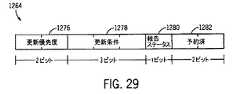
A.ステータス報告
ステータス報告スキーマは、図16においてステータス報告フレーム1182として提示される。ステータス報告スキーマは、別のプロファイルであってもよく、または1つ以上のプロファイルに含まれてもよい(たとえばコアプロファイル)。ある実施の形態では、ステータス報告フレーム1182は、プロファイルフィールド1184、ステータスコードフィールド1186、次のステータスフィールド1188を含み、追加のステータス情報フィールド1190を含んでもよい。A. Status Report The status report schema is presented as
i.プロファイルフィールド
いくつかの実施の形態では、プロファイルフィールド1184は、現在のステータス報告における情報が解釈されることになるプロファイルを定義する4つのバイトのデータを含む。プロファイルフィールド1184の実施の形態が、図17において、2つのサブフィールドで示される。示される実施の形態では、プロファイルフィールド1184はプロファイルIdサブフィールド1192を含み、それは、ステータスコードフィールド1186の値が定義されるプロファイルに対するベンダ特定識別子に対応する16個のビットを含む。プロファイルフィールド1184は、さらに、ベンダIdサブフィールド1194を含み、それは、プロファイルIdサブフィールド1192において識別されるプロファイルを与えるベンダを識別する16個のビットを含む。i. Profile Field In some embodiments, the
ii.ステータスコード
ある実施の形態では、ステータスコードフィールド1186は、報告されているステータスをエンコードする16個のビットを含む。ステータスコードフィールド1186における値は、プロファイルフィールド1184において与えられるベンダIdサブフィール
ド1192およびプロファイルIdサブフィールド1194においてエンコードされる値との関係において解釈される。加えて、ある実施の形態では、ステータスコード空間を、以下において表8に示されるように4つのグループに分割してもよい。ii. Status Code In some embodiments, the
表8は、各特定のプロファイルIdごとに別々に割当てられ用いられる、用いられてもよい一般的なステータスコード範囲を識別するが、いくつかの実施の形態では、いくつかのステータスコードはプロファイルの各々に共通であってもよい。たとえば、これらのプロファイルは、0x00000000のような共通のプロファイル(たとえばコアプロファイル)識別子を用いて識別されてもよい。Table 8 identifies a general status code range that may be used, which is assigned and used separately for each particular profile Id, but in some embodiments some status codes are in the profile. It may be common to each. For example, these profiles may be identified using a common profile (eg, core profile) identifier such as 0x00000000.
iii.次のステータス
いくつかの実施の形態では、次のステータスコードフィールド1188は8つのビットを含んでもよい。次のステータスコードフィールド1188は、現在報告されるステータスのあとに後続のステータス情報があるかどうかを示してもよい。後続のステータス情報が含まれることになる場合には、次のステータスコードフィールド1188は、どのようなタイプのステータス情報が含まれることになるかを示す。いくつかの実施の形態では、次のステータスコードフィールド1188は常に含まれ得、それによって、おそらくはメッセージのサイズを増大させ得る。しかしながら、ステータス情報をともに連鎖させる機会を与えることによって、送信されるデータの全体的な低減に対する可能性が低減され得る。次のステータスフィールド1186が0x00である場合には、どのような後続のステータス情報フィールド1190も含まれない。しかしながら、非ゼロの値は、データが含まれてもよいことを示してもよく、データが含まれる形式(たとえばTLVパケットにおける)を示してもよい。iii. Next Status In some embodiments, the next
iv.追加のステータス情報
次のステータスコードフィールド1188が非ゼロであるときには、追加のステータス情報フィールド1190がメッセージに含まれる。存在する場合には、ステータス項目フィールドは、先行するステータスタイプフィールドの値によって判断されてもよい形式(たとえばTLVフォーマット)でステータスを含んでもよい。iv. Additional Status Information When the following
B.ソフトウェア更新
ソフトウェア更新プロファイルまたはプロトコルは、スキーマの組、およびクライアントがダウンロードまたはインストールしてもよいソフトウェアの存在についての情報にクライアントが気づかされるかまたはそのような情報を求めることを可能にするクライアント/サーバプロトコルである。ソフトウェア更新プロトコルを用いて、ソフトウェアイメージを、プロファイルクライアントに対して、クライアントに既知のフォーマットで与えてもよい。あとのソフトウェアイメージの処理は、包括的、装置特定、またはベンダ特定であってもよく、ソフトウェア更新プロトコルおよび装置によって判断されてもよい。B. Software Update A software update profile or protocol allows a client to become aware of or request information about a set of schemas and the existence of software that the client may download or install. It is a server protocol. A software image may be provided to the profile client in a format known to the client using the software update protocol. Subsequent processing of the software image may be comprehensive, device-specific, or vendor-specific, and may be determined by the software update protocol and device.
i.アプリケーションペイロードに対する一般的なアプリケーションヘッダ
適切に認識および処理されるために、ソフトウェア更新プロファイルフレームは、GMP1128のアプリケーションペイロードフィールド1146内において識別されてもよい。いくつかの実施の形態では、すべてのソフトウェア更新プロファイルフレームは、0x0000000Cのような共通のプロファイルId1176を用いてもよい。加えて、ソフトウェア更新プロファイルフレームは、追加の情報を示すメッセージタイプフィールド1172を含んでもよく、以下の表9および送信されるメッセージのタイプに従って選択されてもよい。i. General application headers for application payloads For proper recognition and processing, software update profile frames may be identified within the
加えて、以下に記載されるように、ソフトウェア更新シーケンスを、サーバが更新をイメージ告知として送信すること、またはクライアントが更新をイメージクエリとして受信することによって開始してもよい。いずれの実施の形態においても、開始イベントからの交換Id1174を、ソフトウェア更新との関連において用いられるすべてのメッセージに対して用いる。In addition, the software update sequence may be initiated by the server sending the update as an image announcement or by the client receiving the update as an image query, as described below. In both embodiments, the exchange Id1174 from the start event is used for all messages used in the context of software updates.
ii.プロトコルシーケンス
図18は、ソフトウェア更新クライアント1198とソフトウェア更新サーバ1200との間におけるソフトウェア更新に対するプロトコルシーケンス1196の実施の形態を示す。ある実施の形態では、ファブリックにおける任意の装置はソフトウェア更新クライアント1198またはソフトウェア更新サーバ1200であってもよい。プロトコルシーケンス1196のある実施の形態は、破線で示されるもののような、一部のソフトウェア更新送信においては省略されてもよいさらなるステップを含んでもよい。ii. Protocol Sequence FIG. 18 shows an embodiment of
1.サービス探索
いくつかの実施の形態では、プロトコルシーケンス1196は、ソフトウェア更新プロファイルサーバが更新の存在を告知することで始まる。しかしながら、示される実施の形態のような他の実施の形態では、プロトコルシーケンス1196は、上に論じられるよう
に、サービス探索1202で始まってもよい。1. 1. Service Search In some embodiments,
2.イメージ告知
いくつかの実施の形態では、イメージ告知メッセージ1204はソフトウェア更新サーバ1200によってマルチキャストまたはユニキャストされてもよい。イメージ告知メッセージ1204は、ファブリックにおける装置に対して、サーバ1200は提供すべきソフトウェア更新を有する旨を知らせる。更新がクライアント1198に適用可能である場合には、イメージ告知メッセージ1204の受信で、ソフトウェア更新クライアント1198はイメージクエリメッセージ1206で応答する。ある実施の形態では、イメージ告知メッセージ1204はプロトコルシーケンス1196に含まれなくてもよい。その代わりに、そのような実施の形態では、ソフトウェア更新クライアント1198は、ポーリングスケジュールを用いて、イメージクエリメッセージ1206をいつ送信すべきかを判断してもよい。2. 2. Image Announcement In some embodiments, the
3.イメージクエリ
ある実施の形態では、イメージクエリメッセージ1206は、上で論じられたように、ソフトウェア更新クライアント1198から、イメージ告知メッセージ1204に応答するか、またはポーリングスケジュールに従って、ユニキャストされてもよい。イメージクエリメッセージ1206は、クライアント1198からのそれ自体についての情報を含む。イメージクエリメッセージ1206のフレームの実施の形態が図19に示される。図19に示されるように、イメージクエリメッセージ1206のある実施の形態は、フレーム制御フィールド1218と、製品仕様フィールド1220と、ベンダ特定データフィールド1222と、バージョン仕様フィールド1224と、ロケール仕様フィールド1226と、被サポート完全性タイプフィールド1228と、被サポート更新スキームフィールド1230とを含んでもよい。3. 3. Image Query In certain embodiments, the
a.フレーム制御
フレーム制御フィールド1218は、1バイトを含み、イメージクエリメッセージ1204についてのさまざまな情報を示す。フレーム制御フィールド1218の一例を図20に示す。示されるように、フレーム制御フィールド1218は3つのサブフィールド:ベンダ特定フラグ1232とロケール仕様フラグ1234と予約済フィールドS3とを含んでもよい。ベンダ特定フラグ1232は、ベンダ特定データフィールド1222がメッセージイメージクエリメッセージに含まれるかどうかを示す。たとえば、ベンダ特定フラグ1232が0であるとき、いかなるベンダ特定データフィールド1222もイメージクエリメッセージには存在しなくてもよいが、ベンダ特定フラグ1232が1であるときには、ベンダ特定データフィールド1222はイメージクエリメッセージに存在してもよい。同様に、ロケール仕様フラグ1234における1値は、ロケール仕様フィールド1226がイメージクエリメッセージに存在することを示し、0値は、ロケール仕様フィールド1226がイメージクエリメッセージに存在しないことを示す。a. Frame control The
b.製品仕様
製品仕様フィールド1220は6バイトフィールドである。製品仕様フィールド1220の実施の形態が図21に示される。示されるように、製品仕様フィールド1220は、3つのサブフィールド:ベンダIdフィールド1236と製品Idフィールド1238と、製品リビジョンフィールド1240とを含んでもよい。ベンダIdフィールド1236は、ソフトウェア更新クライアント1198に対するベンダを示す16個のビットを含む。製品Idフィールド1238は、イメージクエリメッセージ1206をソフトウェア更新クライアント1198として送信している装置製品を示す16個のビットを含む。製品リビジョンフィールド1240は、ソフトウェア更新クライアント1198のリビジョン属性を示す16個のビットを含む。b. Product specifications The
c.ベンダ特定データ
ベンダ特定データフィールド1222は、イメージクエリメッセージ1206に存在するときには、可変数のバイトの長さを有する。ベンダ特定データフィールド1222の存在は、フレーム制御フィールド1218のベンダ特定フラグ1232から判断されてもよい。存在するときには、ベンダ特定データフィールド1222は、上に記載されたように、ソフトウェア更新クライアント1198についてのベンダ特定情報をTLVフォーマットでエンコードする。c. Vendor Specific Data Vendor
d.バージョン仕様
バージョン仕様フィールド1224の実施の形態を図22に示す。バージョン仕様フィールド1224は、2つのサブフィールド:バージョン長フィールド1242とバージョン文字列フィールド1244とに下位分割される可変数のバイトを含む。バージョン長フィールド1242は、バージョン文字列フィールド1244の長さを示す8つのビットを含む。バージョン文字列フィールド1244は、長さが可変であり、バージョン長フィールド1242によって決められる。いくつかの実施の形態では、バージョン文字列フィールド1244は、長さにおいて255個のUTF−8文字を用いて上限を設けられてもよい。バージョン文字列フィールド1244においてエンコードされる値は、ソフトウェア更新クライアント1198に対するソフトウェアバージョン属性を示す。d. Version Specifications An embodiment of the
e.ロケール仕様
ある実施の形態では、ロケール仕様フィールド1226は、フレーム制御1218のロケール仕様フラグ1234が1であるときにイメージクエリメッセージ1206に含まれてもよい。ロケール仕様フィールド1226の実施の形態を図23に示す。ロケール仕様フィールド1226の示される実施の形態は、2つのサブフィールド:ロケール文字列長フィールド1246とロケール文字列フィールド1248とに分割される可変数のバイトを含む。ロケール文字列長フィールド1246は、ロケール文字列フィールド1248の長さを示す8つのビットを含む。ロケール仕様フィールド1226のロケール文字列フィールド1248は、長さが可変であってもよく、ポータブルオペレーティングシステムインターフェイス(POSIX(ポジックス))ロケールコードに基づいてローカル記述をエンコードするUTF−8文字の文字列を含んでもよい。POSIXロケールコードに対する標準フォーマットは、[language[_territory][.codeset][@modifier]]である。た
とえば、オーストラリア英語に対するPOSIX表現はen_AU.UTF8である。e. Locale Specification In certain embodiments, the
f.被サポート完全性タイプ
完全性タイプフィールド1228の実施の形態が図24に示される。被サポート完全性タイプフィールド1228は、2つのサブフィールド:タイプリスト長フィールド1250と完全性タイプリストフィールド1252とに分割される2バイトから4バイトのデータを含む。タイプリスト長フィールド1250は、完全性タイプリストフィールド1252のバイトにおける長さを示す8つのビットを含む。完全性タイプリストフィールド1252は、ソフトウェア更新クライアント1198のソフトウェア更新完全性タイプ属性の値を示す。いくつかの実施の形態では、完全性タイプは以下の表10から導出されてもよい。f. An embodiment of the supported integrity type
完全性タイプリストフィールド1252は、表10からの少なくとも1つの要素または含まれない他のさらなる値を含んでもよい。The
g.被サポート更新スキーム
被サポートスキームフィールド1230の実施の形態を図25に示す。被サポートスキームフィールド1230は、2つのサブフィールド:スキームリスト長フィールド1254と更新スキームリストフィールド1256とに分割される可変数のバイトを含む。スキームリスト長フィールド1254は、更新スキームリストフィールドの長さをバイトで示す8つのビットを含む。被サポート更新スキームフィールド1222の更新スキームリストフィールド1256は、長さが可変であり、スキームリスト長フィールド1254によって決められる。更新スキームリストフィールド1256は、ソフトウェア更新クライアント1198のソフトウェア更新プロファイルの更新スキーム属性を表現する。例示の値の実施の形態が以下の表11に示される。g. Supported Update Scheme An embodiment of the supported
イメージクエリメッセージ1206を受信すると、ソフトウェア更新サーバ1200は、送信された情報を用いて、ソフトウェア更新サーバ1200がソフトウェア更新クライアント1198に対する更新を有するかどうか、およびその更新をどのようにしてソフトウェア更新クライアント1198に送達するのが一番よいかを判断する。Upon receiving the
4.イメージクエリ応答
図18に戻って、ソフトウェア更新サーバ1200がイメージクエリメッセージ1206をソフトウェア更新クライアント1198から受信したのち、ソフトウェア更新サーバ1200はイメージクエリ応答1208で応答する。イメージクエリ応答1208は、更新イメージがなぜソフトウェア更新クライアント1198にとって利用可能でないかを詳
述する情報、またはソフトウェア更新クライアント1198が利用可能なイメージ更新をダウンロードおよびインストールすることができるようにその更新についての情報を含む。4. Image Query Response Returning to FIG. 18, after the
イメージクエリ応答1208のフレームの実施の形態を図26に示す。示されるように、イメージクエリ応答1208は5つの可能なサブフィールド:クエリステータスフィールド1258と統一的リソース識別子(URI)フィールド1260と完全性仕様フィールド1262と更新スキームフィールド1264と更新オプションフィールド1266とを含む。 An embodiment of the frame of
a.クエリステータス
クエリステータスフィールド1258は、可変数のバイトを含み、上においてステータス報告に関して論じられたように、ステータス報告フォーマット化データを含む。たとえば、クエリステータスフィールド1258は、以下の表12に示されるもののような、イメージクエリ応答ステータスコードを含んでもよい。a. Query Status The
b.URI
URIフィールド1260は可変数のバイトを含む。URIフィールド1260の存在はクエリステータスフィールド1258によって判断されてもよい。クエリステータスフィールド1258によって、更新が利用可能である旨が示される場合には、URIフィールド1260が含まれてもよい。URIフィールド1260の実施の形態を図27に示す。URIフィールド1260は、2つのサブフィールド:URI長フィールド1268とURI文字列フィールド1270とを含む。URI長フィールド1268は、URI文字列フィールド1270の長さをUTF−8文字で示す16個のビットを含む。URI文字列フィールド1270は、ソフトウェア更新クライアント1198が、ソフトウェアイメージ更新が存在するときにはそれを見つけ出し、ダウンロードし、およびインストールできるように、提示されているソフトウェアイメージ更新のURI属性を示す。b. URI
The
c.完全性仕様
完全性仕様フィールド1262は、長さが可変であってもよく、更新がソフトウェア更新サーバ1198からソフトウェア更新クライアント1198に利用可能である旨をクエリステータスフィールド1258が示すときに存在してもよい。完全性仕様フィールド1262の実施の形態を図28に示す。示されるように、完全性仕様フィールド1262は
2つのサブフィールド:完全性タイプフィールド1272と完全性値フィールド1274とを含む。完全性タイプフィールド1272は、ソフトウェアイメージ更新に対する完全性タイプ属性を示す8つのビットを含み、上記の表10に示されるものと同様のリストを用いて事前設定されてもよい。完全性値フィールド1274は、イメージ更新メッセージが送信中に完全性を維持したことを検証するよう用いられる完全性値を含む。c. Completeness Specifications The
d.更新スキーム
更新スキームフィールド1264は、8つのビットを含み、更新がソフトウェア更新サーバ1198からソフトウェア更新クライアント1198に利用可能である旨をクエリステータスフィールド1258が示すときに存在する。存在する場合には、更新スキームフィールド1264は、ソフトウェア更新サーバ1198に提示されているソフトウェア更新イメージに対するスキーム属性を示す。d. Update scheme The
e.更新オプション
更新オプションフィールド1266は、8つのビットを含み、更新がソフトウェア更新サーバ1198からソフトウェア更新クライアント1198に利用可能である旨をクエリステータスフィールド1258が示すときに存在する。更新オプションフィールド1266は図29に示されるように下位分割されてもよい。示されるように、更新オプションフィールド1266は4つのサブフィールド:更新優先度フィールド1276と更新条件フィールド1278と報告ステータスフラグ1280と予約済フィールド1282とを含む。いくつかの実施の形態では、更新優先度フィールド1276は2つのビットを含む。更新優先度フィールド1276は、更新の優先度属性を示し、以下の表13に示されるもののような値を用いて判断されてもよい。e. Update option The
更新条件フィールド1278は、いつ更新すべきか、または更新するかどうかを判断すべく、条件的ファクタを判断するのに用いられてもよい3つのビットを含む。たとえば、更新条件フィールド1278における値は以下の表14を用いてデコードされてもよい。The
報告ステータスフラグ1280は、ソフトウェア更新クライアント1198がダウンロード通知メッセージ1210で応答すべきかどうかを示す1つのビットである。報告ステータスフラグ1280が1にセットされる場合には、ソフトウェア更新サーバ1198は、ソフトウェア更新がソフトウェア更新クライアント1200によってダウンロードされたあとにダウンロード通知メッセージ1210が送信されることを要求している。The
イメージクエリ応答1208が、更新が利用可能であることを示す場合には、ソフトウェア更新クライアント1198は、イメージクエリ応答1208において示される時間に、イメージクエリ応答1208に含まれる情報を用いて、その更新をダウンロードする(1210)。 If the
5.ダウンロード通知
更新ダウンロード1210が成功裏に完了したかまたは失敗して報告ステータスフラグ1280が1になったあと、ソフトウェア更新クライアント1198はダウンロード通知メッセージ1212で応答してもよい。ダウンロード通知メッセージ1212は、上で論じられたステータス報告フォーマットに従ってフォーマットされてもよい。ダウンロード通知メッセージ1212において用いられるステータスコードの一例を以下の表15に示す。5. Download Notification Update After the update download 1210 has been successfully completed or failed and the
上に記載されるステータス報告に加えて、ダウンロード通知メッセージ1208は、ダウンロードおよび/またはダウンロードの失敗に関連してもよいさらなるステータス情報を含んでもよい。In addition to the status reports described above,
6.通知応答
ソフトウェア更新サーバ1200は、ダウンロード通知メッセージ1212または更新通知メッセージ1216に応答して通知応答メッセージ1214で応答してもよい。通知応答メッセージ1214は、上に記載されるように、ステータス報告フォーマットを含んでもよい。たとえば、通知応答メッセージ1214は以下の表16に列挙されるステータスコードを含んでもよい。6. The notification response
上記のステータス報告に加えて、通知応答メッセージ1214は、ソフトウェア更新をダウンロード、更新、および/またはダウンロード/更新の失敗に関係してもよいさらなるステータス情報を含んでもよい。In addition to the status report described above, the
7.更新通知
更新が成功裏に完了するかまたは失敗して報告ステータスフラグ1280値が1になったあと、ソフトウェア更新クライアント1198は更新通知メッセージ1216で応答してもよい。更新通知メッセージ1216は上に記載されるステータス報告フォーマットを用いてもよい。たとえば、更新通知メッセージ1216は、以下の表17において列挙されるステータスコードを含んでもよい。7. Update Notification The
上記のステータス報告に加えて、更新通知メッセージ1216は、更新および/または更
新の失敗に関係してもよいさらなるステータス情報を含んでもよい。In addition to the status report described above,
C.データ管理プロトコル
データ管理は、ファブリック内におけるさまざまな電子装置において用いられる共通のプロファイル(たとえばコアプロファイル)に含まれてもよく、または別個のプロファイルとして指定されてもよい。いずれの状況においても、装置管理プロトコル(DMP)を用いて、ノードがノード常駐情報をブラウジング、共有および/または更新してもよい。DMPにおいて用いられるシーケンス1284が図30に示される。シーケンス1284は、被閲覧側ノード1288の常駐データを閲覧および/または変更するよう要求する閲覧側ノード1286を示す。加えて、閲覧側ノード1286は、スナップショット要求、閲覧がある時間期間にわたって持続する旨の監視要求、または他の好適な閲覧タイプなどのような、いくつかの閲覧オプションのうちの1つを用いて、常駐データを閲覧することを要求してもよい。各メッセージは、図15を参照して記載されるアプリケーションペイロード1146に対するフォーマットに従う。たとえば、各メッセージは、0x235A0000のような、データ管理プロファイルおよび/または関係のあるコアプロファイルに対応するプロファイルId1176を含む。各メッセージは、さらに、メッセージタイプ1172を含む。メッセージタイプ1172は、ビューに対する閲覧タイプのような、会話に関係するさまざまなファクタを判断するのに用いられてもよい。たとえば、いくつかの実施の形態では、メッセージタイプフィールド1172は以下の表18に従ってエンコード/デコードされてもよい。C. Data Management Protocol Data management may be included in a common profile (eg, a core profile) used by various electronic devices in the fabric, or may be specified as a separate profile. In either situation, the node may browse, share, and / or update node-resident information using the Device Management Protocol (DMP). The
i.ビュー要求
ビュー要求メッセージ1290は、上で論じられたように、ノード常駐データを閲覧するよう要求するが、要求のタイプはメッセージタイプフィールド1172によって判断されてもよい。したがって、各要求タイプは異なるビュー要求フレームを含んでもよい。i. View Requests
1.スナップショット要求
スナップショット要求は、閲覧側ノード1286が今後の更新を要求することなく被閲覧側ノード1288上のノード常駐データに対する即時ビューを所望するときに閲覧側ノード1286によって送信されてもよい。スナップショット要求フレーム1292の実施の形態を図31に示す。1. 1. Snapshot Request A snapshot request may be sent by the viewing node 1286 when the viewing node 1286 wants an immediate view of the node-resident data on the viewed
図31に示されるように、スナップショット要求フレーム1292は、長さが可変であってもよく、3つのフィールド:ビューハンドルフィールド1294とパス長リストフィールド1296とパスリストフィールド1298とを含んでもよい。ビューハンドルフィールド1294は、要求されたビューを識別するよう「ハンドル」を与える2つのビット
を含んでもよい。いくつかの実施の形態では、ビューハンドルフィールド1294は、16ビットの乱数または16ビットのシーケンス番号を、要求が形成されるときに閲覧側ノード1286上で実行される一意性チェックとともに用いて、事前設定される。パスリスト長フィールド1296は、パスリストフィールド1298の長さを示す2つのバイトを含む。パスリストフィールド1298は、長さが可変であり、パスリスト長フィールド1296の値によって示される。パスリストフィールド1298の値はノードに対するスキーマパスを示す。As shown in FIG. 31, the
スキーマパスは、ノードに常駐するスキーマの一部であるデータ項目またはコンテナに対する簡潔な記述である。たとえば、図32は、プロファイルスキーマ1300の一例を与える。示されるプロファイルスキーマ1300においては、データ項目1302へのパスがバイナリフォーマットで“Foo:bicycle:mountain”(Foo:自転車:マウンテン)と
書かれてもよい。パスのバイナリフォーマットは、図33に示されるように、プロファイルバイナリフォーマット1304として表現されてもよい。プロファイルバイナリフォーマット1304は、2つのサブフィールド:プロファイル識別子フィールド1306とTLVデータフィールド1308とを含む。プロファイル識別子フィールド1306は、どのプロファイルが参照されているか(たとえばFooプロファイル)を識別する。TLVデ
ータフィールド1308パス情報。先に論じられたように、TLVデータは、同封されたデータについての情報を含むタグフィールドを含む。図32のFooプロファイルを指すよ
う用いられるタグフィールド値は表19にリスト化された値と同様であってもよい。A schema path is a concise description of a data item or container that is part of a schema that resides on a node. For example, FIG. 32 gives an example of
表19および図32のFooプロファイルを用いて、パス“Foo:bicycle:mountain”を表わ
すTLVフォーマットにおけるバイナリ文字列が、以下の表20に示されるように表現されてもよい。Using the Foo profile in Table 19 and FIG. 32, a binary string in TLV format representing the path “Foo: bicycle: mountain” may be represented as shown in Table 20 below.
閲覧側ノード1286が、プロファイルスキーマ(たとえば図33のFooプロファイルス
キーマ)に定義される全データを受信することを所望する場合には、ビュー要求メッセージ1290は、「ニル」項目(たとえば0x0D00 TLおよびコンテナを指す空の長さを要求
してもよい。If the viewing node 1286 wants to receive all the data defined in the profile schema (eg, the Foo profile schema in Figure 33), the
2.監視要求
閲覧側ノード1286がスナップショット以上のものを所望する場合には、閲覧側ノード1286は監視要求を要求してもよい。監視要求は、被閲覧側ノード1288における当該のデータに変更がなされるときに被閲覧側ノード1288に対して更新を送信するよう求めて、閲覧側ノード1286がそのデータの同期されたリストを保持できるようにする。監視要求フレームは、図31のスナップショット要求とは異なるフォーマットを有してもよい。監視要求フレーム1310の実施の形態が図34に示される。監視要求フレーム1310は4つのフィールド:ビューハンドルフィールド1312とパスリスト長フィールド1314とパスリストフィールド1316と変更カウントフィールド1318とを含む。ビューハンドルフィールド1312、パスリスト長フィールド1314、およびパスリストフィールドは、それぞれ、図31のスナップショット要求のビューハンドルフィールド1294、パスリスト長フィールド1296、およびパスリストフィールド1298と同様にフォーマットされてもよい。さらなるフィールドの変更カウントフィールド1318は、更新が閲覧側ノード1286に送信される要求されたデータの変更数のしきい値を示す。いくつかの実施の形態では、変更カウントフィールド1318の値が0である場合には、被閲覧側ノード1288は、更新をいつ送信するべきかを被送信側ノード1288自身で判断してもよい。変更カウントフィールド1318の値が0でない場合には、変更の数がその値と等しくなった後、更新が閲覧側ノード1286に送信される。2. 2. Monitoring Request If the viewing node 1286 wants more than a snapshot, the viewing node 1286 may request a monitoring request. The monitoring request asks the viewed
3.周期的更新要求
第3のタイプのビューが、さらに、閲覧側ノード1286によって要求されてもよい。この第3のタイプのビューは周期的更新と称される。周期的更新はスナップショットビューを周期的更新と並んで含む。理解され得るように、周期的更新要求はスナップショット要求と同様であってもよいが、さらなる情報が更新期間を決める。たとえば、周期的更新要求フレーム1320の実施の形態が図35に示される。周期的更新要求フレーム1320は4つのフィールド:ビューハンドルフィールド1322とパスリスト長フィールド1324とパスリストフィールド1326と更新期間フィールド1328とを含む。ビューハンドルフィールド1322とパスリスト長フィールド1324とパスリストフィールド1326とはスナップショット要求フレーム1292におけるそれらの対応のフィールドと同様にフォーマットされてもよい。更新期間フィールド1328は、長さが4つのバイトであり、関連する時間単位(たとえば秒)で更新間において経過する時間期間に対応する値を含む。3. 3. Periodic update request A third type of view may also be requested by the viewing node 1286. This third type of view is referred to as periodic updates. Periodic updates include snapshot views alongside periodic updates. As can be understood, the periodic update request may be similar to the snapshot request, but additional information determines the update period. For example, an embodiment of the periodic
4.リフレッシュ要求
閲覧側ノード1286が更新されたスナップショットを受信することを所望する場合には、閲覧側ノード1286は、ビュー要求メッセージ1290を、図36に示されるリフレッシュ要求フレーム1330の形式で送信してもよい。リフレッシュ要求フレーム1330は、本質的には、リフレッシュ要求フレーム1330におけるビューハンドル値を用いて、被閲覧側ノード1228が前の要求として認識することができる前のスナップショット要求から、スナップショットビューハンドルフィールド(たとえばビューハンドルフィールド1294)を再送信する。4. Refresh Request If the viewing node 1286 wishes to receive an updated snapshot, the viewing node 1286 sends a
5.ビュー取消要求
閲覧側ノード1286が進行中のビュー(たとえば周期的更新または監視ビュー)を取消すよう所望するときには、閲覧側ノード1286は、ビュー要求メッセージ1290を
、図37に示されるようなビュー取消要求フレーム1332の形式で送信してもよい。ビュー取消要求フレーム1332は、本質的に、リフレッシュ要求フレーム1330におけるビューハンドル値を用いて、現在の周期的更新または監視ビューを取消すために、被閲覧側ノード1288が前の要求として認識できる前の要求からの前の周期的更新または監視ビュー(たとえばビューハンドルフィールド1310または1322)からビューハンドルフィールドを再送信する。5. View Cancellation Request When the viewing node 1286 wishes to cancel an in-progress view (eg, a periodic update or watched view), the viewing node 1286 issues a
ii.ビュー応答
図30に戻って、被閲覧側ノード1288がビュー要求メッセージ1290を受信した後、被閲覧側ノード1288はビュー応答メッセージ1334で応答する。ビュー応答メッセージフレーム1336の一例が図38に示される。ビュー応答メッセージフレーム1336は3つのフィールド:ビューハンドルフィールド1338とビュー要求ステータスフィールド1240とデータ項目リスト1242とを含む。ビューハンドルフィールド1338は、上において参照されるビューハンドルフィールド1338のうちの任意のものと同様にフォーマットされてもよい。加えて、ビューハンドルフィールド1338は、ビュー応答メッセージ1334が応答しているビュー要求メッセージ1290からのそれぞれのビューハンドルフィールドと一致する値を含む。ビュー要求ステータスフィールド1340は、ビュー要求のステータスを示す可変長フィールドであり、上で論じられたステータス更新フォーマットに従ってフォーマットされてもよい。データ項目リストフィールド1342は、ビュー要求が成功した旨をビュー要求ステータスフィールド1340が示すときに存在する可変長フィールドである。存在する場合には、データ項目リストフィールド1342は、ビュー要求メッセージ1290のパスリストに対応する要求されるデータの順序づけられたリストを含む。さらに、データ項目リストフィールド1342におけるデータは、上で論じられるように、TLVフォーマットでエンコードされてもよい。ii. View Response Returning to FIG. 30, after the viewed
iii.更新要求
上で論じられたように、いくつかの実施の形態では、被閲覧側ノード1288は閲覧側ノード1286に更新を送信してもよい。これらの更新は更新要求メッセージ1344として送信されてもよい。更新要求メッセージ1344は、更新要求のタイプによって、指定されたフォーマットを含んでもよい。たとえば、更新要求は、明示的な更新要求であるか、またはメッセージId1172によって識別されてもよいビュー更新要求フィールドであってもよい。iii. Update Request As discussed above, in some embodiments, the viewed
1.明示的更新要求
明示的更新要求は、任意の時間において、ファブリック1000における他のノードからの情報を所望する結果として送信されてもよい。明示的更新要求は、図39に示される更新要求フレーム1346でフォーマットされてもよい。示される更新要求フレーム1346は4つのフィールド:更新ハンドルフィールド1348とパスリスト長フィールド1350とパスリストフィールド1352とデータ項目リストフィールド1354とを含む。1. 1. Explicit Update Request An explicit update request may be sent at any time as a desired result of information from other nodes in
更新ハンドルフィールド1348は、乱数または連続数、および更新要求またはその要求に対する応答を識別する一意性チェックで事前設定されてもよい。パスリスト長フィールド1350は、パスリストフィールド1352の長さを示す2つのバイトを含む。パスリストフィールド1352は、上記のように、パスのシーケンスを示す可変長フィールドである。データ項目リストフィールド1354はデータ項目リストフィールド1242と同様にフォーマットされてもよい。 The update handle field 1348 may be preset with a random number or sequence, and a uniqueness check that identifies the update request or the response to that request. The pathlist length field 1350 contains two bytes indicating the length of the
2.ビュー更新要求
ビュー更新要求メッセージは、以前に別のノードのスキーマに対するビューを要求した
ノード、またはそれ自身のデータに対するビューを別のノードに代わって確立したノードによって送信されてもよい。ビュー更新要求フレーム1356の実施の形態が図40に示される。ビュー更新要求フレーム1356は4つのフィールド:更新ハンドルフィールド1358とビューハンドルフィールド1360と更新項目リスト長フィールド1362と更新項目リストフィールド1364とを含む。更新ハンドルフィールド1358は、更新ハンドルフィールド1348に関して上で論じられたフォーマットを用いて構成されてもよい。ビューハンドルフィールド1360は、同じビューハンドルを有する関係のあるビュー要求メッセージ1290によって形成されるビューを識別する2つのバイトを含む。更新項目リスト長フィールド1362は、2つのバイトを含み、更新項目リストフィールド1364に含まれる更新項目の数を示す。2. 2. View update request A view update request message may be sent by a node that previously requested a view for another node's schema, or a node that established a view for its own data on behalf of another node. An embodiment of the view
更新項目リストフィールド1364は、可変数のバイトを含み、更新された値を構成するデータ項目をリスト化する。各更新された項目リストは複数の更新項目を含んでもよい。個々の更新項目は、図41に示される更新項目フレーム1366に従ってフォーマットされる。各更新項目フレーム1366は3つのサブフィールド:項目インデックスフィールド1368と項目タイムスタンプフィールド1370とデータ項目フィールド1372とを含む。項目インデックスフィールド1368は、更新が要求されているビューと、データ項目フィールド1372に対するそのビューのパスリストにおけるインデックスとを示す2つのバイトを含む。 The update
項目タイムスタンプフィールド1370は、4つのバイトを含み、変更から通信されている更新がなされるまでの経過時間を(たとえば秒で)示す。2つ以上の変更がデータ項目に対してなされた場合には、項目タイムスタンプフィールド1370は最も最近の変更または最も早い変更を示してもよい。データ項目フィールド1372は、更新された情報として受信されることになるTLVフォーマットでエンコードされた可変長フィールドである。 The
iv.更新応答
更新が受信された後、ノード(たとえば閲覧側ノード1286)は更新応答メッセージ1374を送信してもよい。更新応答メッセージ1374は、図42に示される更新応答フレーム1376を用いてエンコードされてもよい。更新応答フレーム1376は2つのフィールド:更新ハンドルフィールド1378と更新要求ステータスフィールド1380とを含む。更新ハンドルフィールド1378は、更新応答メッセージ1374が応答している更新要求メッセージ1344の更新ハンドルフィールドの値に対応する。更新要求ステータスフィールド1380は、上で論じられたステータス報告フォーマットに従って更新のステータスを報告する。加えて、DMPを用いるプロファイル(たとえばコアプロファイルまたはデータ管理プロファイル)は、以下の表21に列挙されるもののようなプロファイル特定コードを含んでもよい。iv. Update Response After the update is received, the node (eg, viewing node 1286) may send an
D.大容量転送
いくつかの実施の形態では、大容量データファイル(たとえばセンサデータ、ログ、または更新イメージ)をファブリック1000におけるノード/サービス間で転送することが望ましくあり得る。大容量データの転送を可能にするために、別のファイルまたはプロトコルを1つ以上のプロファイルに組込んで、ノード/ノードにおけるサービスに利用可能にされてもよい。大容量データ転送プロトコルは、データファイルを、データの集まりとして、メタデータアタッチメントとともにモデル化してもよい。ある実施の形態では、データは不透明であってもよいが、メタデータを用いて、要求されたファイル転送に進んでもよいかを判断してもよい。D. Mass Transfer In some embodiments, it may be desirable to transfer mass data files (eg, sensor data, logs, or updated images) between nodes / services in
大容量転送に関与する装置は、一般的に、大容量転送通信およびイベント形成に従って分割されてもよい。図43に示されるように、大容量転送における各通信1400は、送信側1402を含み、それは、大容量データ1404を受信するノード/サービスである受信側1406に大容量データ1404を送信するノード/サービスである。いくつかの実施の形態では、受信側は、ステータス情報1408を送信側1402に送信して、大容量転送のステータスを示してもよい。加えて、大容量転送イベントは、送信側1402(たとえばアップロード)または受信側1406(たとえばダウンロード)のどちらかが開始側として開始されてもよい。開始側に応答するノード/サービスは、大容量データ転送において応答側と称されてもよい。 The devices involved in mass transfer may generally be partitioned according to mass transfer communication and event formation. As shown in FIG. 43, each
大容量データ転送は同期モードまたは非同期のいずれかを用いて生じてもよい。データが転送されるモードは、大容量データが送信される基底プロトコル(たとえばUDPまたはTCP)などのようなさまざまなファクタを用いて判断されてもよい。無接続プロトコ
ル(たとえばUDP)においては、大容量データは同期モードを用いて転送されてもよく、それは、ノード/サービスの1つ(「ドライバ」)が、転送が進行する速度を制御することを可能にする。ある実施の形態では、同期モード大容量データ転送における各メッセージの後、大容量データ転送において次のメッセージを送信する前に、肯定応答が送信されてもよい。ドライバは送信側1402または受信側1406であってもよい。いくつかの実施の形態では、ドライバは、オンライン状態とオフライン状態との間をトグルして、オンライン状態にあるときには転送を進めるようメッセージを送信してもよい。接続指向型プロトコル(たとえばTCP)を用いての大容量データ転送においては、大容量データは、連続するメッセージを送信する前の肯定応答または単一のドライバを用いない非同期モードを用いて転送されてもよい。Mass data transfer may occur using either synchronous mode or asynchronous. The mode in which the data is transferred may be determined using various factors such as the underlying protocol (eg UDP or TCP) in which the large amount of data is transmitted. In a disconnected protocol (eg UDP), large amounts of data may be transferred using synchronous mode, which means that one of the nodes / services (the "driver") controls the rate at which the transfer proceeds. to enable. In certain embodiments, an acknowledgment may be sent after each message in the synchronous mode mass data transfer before sending the next message in the mass data transfer. The driver may be the transmitting
大容量データ転送が同期モードまたは非同期モードを用いて実行されるかどうかに関わらず、メッセージのタイプは、アプリケーションペイロード1146におけるメッセージタイプ1172を用いて、アプリケーションペイロードにおけるプロファイルId1176に従って判断されてもよい。表22は、プロファイルId1176における大容量データ転送プロファイル値と関連して用いられてもよいメッセージタイプの一例を含む。 Regardless of whether mass data transfer is performed using synchronous or asynchronous mode, the message type may be determined using
i.SendInit(送信開始)
SendInit(送信開始)メッセージ1420の実施の形態を図44に示す。SendInitメッセージ1420は7つのフィールド:転送制御フィールド1422と範囲制御フィールド1424とファイル指示子長フィールド1426と提案される最大ブロックサイズフィールド1428と開始オフセットフィールド1430と長さフィールド1432とファイル指示子フィールド1434とを含んでもよい。i. SendInit
An embodiment of the
転送制御フィールド1422は、図45に示されるバイトのデータを含む。転送制御フィールドは少なくとも4つのフィールド:非同期フラグ1450とRドライブフラグ1452とSドライブフラグ1454とバージョンフィールド1456とを含む。非同期フラグ1450は、提案される転送が同期モードまたは非同期モードを用いて実行されてもよいかどうかを示す。Rドライブフラグ1452およびSドライブフラグ1454は、各々、それぞれ、受信側1402または送信側1408が同期モード転送を駆動する状態で、受信側1406がデータを転送する能力があるかどうかを示す。 The
範囲制御フィールド1424は、図46に示される範囲制御フィールド1424のようなバイトのデータを含む。示される実施の形態では、範囲制御フィールド1424は少なくとも3つのフィールド:BigExtentフラグ1470と開始オフセットフラグ1472と
有限長フラグ1474とを含む。有限長フラグ1474は転送が有限長を有するかどうかを示す。有限長フラグ1474は、長さフィールド1432がSendInitメッセージ1420に存在するかどうかを示し、BigExtentフラグ1470は長さフィールド1432に対
するサイズを示す。たとえば、いくつかの実施の形態では、BigExtentフラグ1470に
おける1の値は長さフィールド1432が8バイトであることを示す。そうでない場合には、長さフィールド1432は、存在する場合には、4バイトである。転送が有限長を有する場合には、開始オフセットフラグ1472は、開始オフセットがあるかどうかを示す。開始オフセットがある場合には、BigExtentフラグ1470は開始オフセットフィール
ド1430に対する長さを示す。たとえば、いくつかの実施の形態では、BigExtentフラ
グ1470における1の値は、開始オフセットフィールド1430が8バイトであることを示す。そうでない場合には、開始オフセットフィールド1430は、存在する場合には4バイトである。The
図44に戻って、ファイル指示子長フィールド1426は、ファイル指示子フィールド1434の長さを示す2つのバイトを含む。ファイル指示子フィールド1434は、ファイル指示子長フィールド1426に依存する可変長フィールドである。最大ブロックサイズフィールド1428は、単一の転送において転送されてもよいブロックの最大サイズを提案する。 Returning to FIG. 44, the file
開始オフセットフィールド1430は、存在するときには、BigExtentフラグ1470
によって示される長さを有する。開始オフセットフィールド1430の値は、送信側1402が転送を開始してもよい転送されるべきファイル内の位置を示し、大きなファイル転送が複数の大容量転送セッションにセグメント化されることを本質的に可能にする。The start offset field 1430, when present, has the
Has the length indicated by. The value of the start offset field 1430 indicates the position in the file to be transferred where the
長さフィールド1432は、存在するときには、転送されるべきファイルが有限長を有する旨を有限長フィールド1474が示す場合には、そのファイルの長さを示す。いくつかの実施の形態では、その長さが達成される前に受信側1402が最終のブロックを受信する場合には、受信側は、以下に論じられるように、転送は失敗したと考え、エラーを報告してもよい。 The length field 1432, when present, indicates the length of the file to be transferred, if the
ファイル指示子フィールド1434は、送信されるべきデータを識別するよう送信側1402によって選択される可変長識別子である。いくつかの実施の形態では、送信側1402および受信側1406は、送信前にファイルに対する識別子を交渉してもよい。他の実施の形態では、受信側1406は、メタデータをファイル指示子フィールド1434とともに用いて、転送を受入れるべきかどうか、およびそのデータを処理すべきかどうかを判断してもよい。ファイル指示子フィールド1434の長さはファイル指示子長フィールド1426から判断されてもよい。いくつかの実施の形態では、SendInitメッセージ1420は、さらに、TLVフォーマットでエンコードされる可変長のメタデータフィールド1480を含んでもよい。メタデータフィールド1480は、開始側が、転送されるべきファイルについてのアプリケーション特定情報のようなさらなる情報を送信することを可能にする。いくつかの実施の形態では、メタデータフィールド1480を用いて、大容量データ転送前にファイル指示子フィールド1434と交渉することを回避してもよい。
ii.SendAccept(送信受入)
送信受入メッセージは、転送のために選択された転送モードを示すよう応答側から送信される。SendAcceptメッセージ1500の実施の形態を図47に示す。SendAcceptメッセージ1500は、SendInitメッセージ1420の転送制御フィールド1422と同様の転
送制御フィールド1502を含む。しかしながら、いくつかの実施の形態では、Rドライブフラグ1452またはSドライブフラグ1454のみが転送制御フィールド1502において非ゼロの値を有して、送信側1402または受信側1406を同期モード転送のドライバとして識別してもよい。SendAcceptメッセージ1500は、さらに、転送に対する最大ブロックサイズを示す最大ブロックサイズフィールド1504を含む。ブロックサイズフィールド1504はSendInitメッセージ1420の最大ブロックフィールド1428の値と等しくてもよいが、最大ブロックサイズフィールド1504の値は最大ブロックフィールド1428において提案される値より小さくてもよい。最後に、SendAcceptメッセージ1500は、受信側1506が転送について送信側1402に渡してもよい情報を示すメタデータフィールド1506を含んでもよい。ii. SendAccept
The send / receive message is sent by the responder to indicate the transfer mode selected for transfer. An embodiment of the Send Accept
iii.SendReject(送信拒絶)
受信側1206がSendInitメッセージの後に転送を拒絶するときには、受信側1206はSendReject(送信拒絶)メッセージを送信して、1つ以上の問題が送信側1202と受信側1206との間における大容量データ転送に関して存在することを示してもよい。送信拒絶メッセージは、上に記載され図48に示されるステータス報告フォーマットに従ってフォーマットされてもよい。送信拒絶フレーム1520は、転送を拒絶する理由を示す2つのバイトを含むステータスコードフィールド1522を含んでもよい。ステータスコードフィールド1522は、下の表23に示されるように列挙されるものと同様の値を用いてデコードされてもよい。iii. SendReject
When the receiving
いくつかの実施の形態では、送信拒絶メッセージ1520は次のステータスフィールド1524を含んでもよい。次のステータスフィールド1524は、存在するときには、ステータス報告フレームの次のステータスフィールド1188に関して上で論じられたようにフォーマットされエンコードされてもよい。ある実施の形態では、送信拒絶メッセージ1520はさらなる情報フィールド1526を含んでもよい。さらなる情報フィールド1526は、存在するときには、さらなるステータスについての情報を格納し、上で論じられたTLVフォーマットを用いてエンコードされてもよい。In some embodiments, the
iv.ReceiveInit(受信開始)
ReceiveInit(受信開始)メッセージは、開始側としての受信側1206によって送信
されてもよい。ReceiveInitメッセージは、図44に示されるSendInitメッセージ148
0と同様にフォーマットおよびエンコードされてもよいが、BigExtentフィールド147
0は、受信側1206が処理することができる最大ファイルサイズを指定する最大長フィールドとして称されてもよい。iv. ReceiveInit
The ReceiveInit message may be transmitted by the receiving
May be formatted and encoded as 0, but BigExtent field 147
0 may be referred to as the maximum length field that specifies the maximum file size that the receiving
v.ReceiveAccept(受信受入)
送信側1202がReceiveInitメッセージを受信すると、送信側1202はReceiveAccept(受信受入)メッセージで応答してもよい。ReceiveAcceptメッセージは、図49に示
されるReceiveAcceptメッセージ1540としてフォーマットおよびエンコードされても
よい。ReceiveAcceptメッセージ1540は4つのフィールド:転送制御フィールド15
42と範囲制御フィールド1544と最大ブロックサイズフィールド1546と、ときとして長さフィールド1548とを含んでもよい。ReceiveAcceptメッセージ1540は、
図47のSendAcceptメッセージ1502と同様にフォーマットされてもよいが、第2のバイトは範囲制御フィールド1544を示す。さらに、範囲制御フィールド1544は、図46の範囲制御フィールド1424に関して上で論じられた同じ方法を用いてフォーマットおよびエンコードされてもよい。v. ReceiveAccept
When the
It may include 42, a
It may be formatted in the same manner as the Send Accept
vi.ReceiveReject(受信拒絶)
送信側1202が、受信側1206にファイルを転送することで問題に遭遇する場合には、送信側1202は、両方とも上で論じられた、ステータス報告フォーマットを用いてSendRejectメッセージ48と同様にフォーマットおよびエンコードされるReceiveReject
(受信拒絶)メッセージを送信してもよい。しかしながら、ステータスコードフィールド1522は、以下に表24に示されるように列挙されるものと同様の値を用いてエンコード/デコードされてもよい。vi. ReceiveReject
If
(Rejection) A message may be sent. However, status code field 1522 may be encoded / decoded using values similar to those listed below, as shown in Table 24.
vii.BlockQuery(ブロッククエリ)
BlockQueryメッセージは、次のブロックのデータを要求するよう駆動側受信側1202によって同期モード大容量データ転送において送信されてもよい。BlockQueryは、明示的でない肯定応答が送信された場合には前のデータのブロックの受信を暗示的に肯定応答する。非同期転送を用いる実施の形態では、BlockQueryメッセージは伝送プロセスから省略されてもよい。vii. BlockQuery
The BlockQuery message may be sent by the drive-
viii.Block(ブロック)
大容量データ転送において送信されるデータのブロックは、0より大きく、かつ送信側1202および受信側1206によって同意された最大ブロックサイズ未満の、任意の長さを含んでもよい。viii. Block
The block of data transmitted in a large data transfer may include any length greater than 0 and less than the maximum block size agreed by the transmitting
ix.BlockEOF(ファイルの終わりブロック)
データ転送における最終のブロックはファイルの終わりブロック(BlockEOF)として提示されてもよい。BlockEOFは0と最大ブロックサイズとの間の長さを有してもよい。受信
側1206が、予め交渉されたファイルサイズ(たとえば長さフィールド1432)と実際に転送されたデータの量との間に相違を見出す場合には、受信側1206は、以下に論じられるように、失敗を示すError(エラー)メッセージを送信してもよい。ix. BlockEOF (end block of file)
The final block in the data transfer may be presented as the end block of the file (BlockEOF). BlockEOF may have a length between 0 and the maximum block size. If the
x.Ack(肯定応答)
送信側1202が同期モード転送を駆動している場合には、送信側1202は、Block
の送信後と次のBlockの送信前との間に肯定応答(Ack)を受信するまで待機してもよい。受信側が同期モード転送を駆動している場合には、受信側1206は、明示的AckまたはBlockQueryのいずれかを送信して、前のブロックの受信を肯定応答してもよい。さらに、
非同期モード大容量転送においては、Ackメッセージは伝送プロセスから全く省略されて
もよい。x. Ack (acknowledgement)
When the transmitting
You may wait until an acknowledgment (Ack) is received between after the transmission of and before the transmission of the next block. If the receiver is driving synchronous mode transfers, the
In asynchronous mode mass transfer, the Ack message may be omitted entirely from the transmission process.
xi.AckEOF(ファイルの終わりの肯定応答)
ファイルの終わりの肯定応答(AckEOF)は、同期モードまたは非同期モードにおいて送信される大容量転送において送信されてもよい。AckEOFを用いて、受信側1206は、転送におけるすべてのデータが受信されたことを示し、大容量データ転送セッションの終わりを信号送信する。xi. AckEOF (acknowledgement at the end of the file)
An acknowledgment at the end of the file (AckEOF) may be sent on a mass transfer sent in synchronous or asynchronous mode. Using AckEOF, the receiving
xii.Error
通信におけるある問題の発生で、送信側1202または受信側1206は、エラーメッセージを送信して、大容量データ転送セッションを早く終わらせてもよい。エラーメッセージは、上で論じられたステータス報告フォーマットに従ってフォーマットおよびエンコードされてもよい。たとえば、エラーメッセージは、図48のSendRejectフレーム1520と同様にフォーマットされてもよい。しかしながら、ステータスコードは、値が以下の表25に列挙されるものを含む、および/またはそれらと同様である状態で、エンコード/デコードされてもよい。xii. Error
In the event of a communication problem, the transmitting
上に記載される具体的な実施の形態は例示によって示されたものであり、これらの実施の形態はさまざまな修正および代替形式が可能であり得ることが理解されるべきである。さらに、特許請求の範囲は開示される特定の形式に限定されるよう意図されるものではなく、本開示の精神および範囲内に入るすべての修正物、均等物および代替物を包含することが理解されるべきである。 The specific embodiments described above are illustrated by way of illustration, and it should be understood that these embodiments may have various modifications and alternative forms. Furthermore, it is understood that the claims are not intended to be limited to the particular form disclosed, but include all modifications, equivalents and alternatives that fall within the spirit and scope of this disclosure. It should be.
Claims (14)
Translated fromJapanese前記電子装置は、
前記プラットフォーム層を介したメッセージの送受信において、他の電子装置との間にトランスポート層において特定されるプロトコルに従って接続を確立して前記他の電子装置との間でメッセージを送信または受信し、
前記プラットフォーム層で、前記メッセージをアプリケーション層が用いる形式に変換するよう構成され、
前記メッセージは、前記電子装置または前記他の電子装置で動作を起こさせ、前記メッセージは、
メッセージフォーマットを含み、前記メッセージフォーマットは、
メッセージタイプフィールドを含み、前記メッセージタイプフィールドは、送信されているメッセージのタイプを指定するメッセージオペレーションコードを示すよう構成され、前記メッセージタイプフィールドは、受信側装置に前記指定されたメッセージの要求のタイプに対応するフレーム構成に従って前記メッセージを処理させ、前記メッセージフォーマットはさらに、
前記メッセージタイプフィールドの直ぐ後に続く交換IDフィールドを含み、前記交換IDフィールドは前記メッセージが前記電子装置に対して生じるディスカッションを一意に識別するように構成され、前記メッセージフォーマットはさらに、
前記交換IDフィールドの直ぐ後に続くプロファイルIDフィールドを含み、前記プロファイルIDフィールドは、前記受信側装置に、前記メッセージタイプフィールドを解釈させて、複数のスキーマのうちの少なくとも1つのスキーマを送信されたデータに対して識別させ、複数のプロファイルのうちのあるプロファイルを示し、前記複数のスキーマの各スキーマは、前記プロファイルおよびスキーマに従ってエンコーディングフォーマットを示し、前記メッセージフォーマットはさらに、
前記プロファイルIDフィールドに続くアプリケーションペイロードフィールドを含み、前記アプリケーションペイロードフィールドは、前記電子装置のアプリケーション層と関連付けられるデータを含み、識別された前記スキーマは、前記受信側装置に前記アプリケーションペイロードフィールドを当該スキーマを用いてデコードさせる、電子装置。An electronic device that is configured to send or receive messages to or receive messages from other electronic devices via the platform layer.
The electronic device
In sending and receiving messages via the platform layer, a connection is established with other electronic devices according to the protocol specified in the transport layer to send or receive messages with the other electronic devices.
The platform layer is configured to translate the message into the format used by the application layer.
The message causes an operation in the electronic device or the other electronic device, and the message is
The message format includes a message format.
The message type field includes a message type field and is configured to indicate a message operation code that specifies the type of message being sent, and the message type field is the type of request for the specified message to the receiving device. The message is processed according to the frame configuration corresponding to, and the message format further
The exchange ID field comprises an exchange ID field immediately following the message type field, the exchange ID field is configured to uniquely identify the discussion in which the message occurs to the electronic device, and the message format further comprises.
The profile ID field includes a profile ID field immediately following the exchange ID field, which causes the receiving device to interpret the message type field and transmits at least one of a plurality of schemas. Each schema of the plurality of schemas indicates an encoding format according to the profile and the schema, and the message format further indicates a profile among the plurality of profiles.
The profile ID field includes an application payload field following the profile ID field, the application payload field contains data associated with the application layer of the electronic device, and the identified schema places the application payload field on the receiving device. An electronic device that is decoded using.
前記電子装置に利用可能な基本的なスキーマの組を含むコアプロファイル、
前記電子装置が前記他の電子装置に位置するデータにアクセスすることを可能にするデータ管理スキーマの組を含むデータ管理プロファイル、
前記電子装置が大容量データを前記他の電子装置に、または前記他の電子装置から転送することを可能にする大容量データ転送スキーマの組を含む大容量データ転送プロファイル、
前記電子装置が前記他の電子装置からステータス情報を送信または受信することを可能にするステータス報告スキーマの組を含むステータス報告プロファイル、または、
前記電子装置が前記他の電子装置からソフトウェア更新イメージを送信または受信することを可能にするソフトウェア更新スキーマの組を含むソフトウェア更新プロファイルを含む、請求項1〜請求項3のいずれか1項に記載の電子装置。The profile shown above
A core profile containing a set of basic schemas available for said electronic device,
A data management profile that includes a set of data management schemas that allow the electronic device to access data located in the other electronic device.
A large-capacity data transfer profile, which comprises a set of large-capacity data transfer schemas that allow the electronic device to transfer large amounts of data to or from the other electronic device.
A status reporting profile that includes a set of status reporting schemas that allows the electronic device to send or receive status information from the other electronic device, or
The first aspect of any one of claims 1 to 3, wherein the electronic device includes a software update profile including a set of software update schemas that enables the electronic device to send or receive a software update image from the other electronic device. Electronic device.
前記電子装置は、
プラットフォーム層を介したメッセージの送受信において、他の電子装置との間にトランスポート層において特定されるプロトコルに従って接続を確立して前記他の電子装置との間でメッセージを送信または受信し、
前記プラットフォーム層で、前記メッセージをアプリケーション層が用いる形式に変換するよう構成され、
前記方法は、
メッセージフォーマットを用いてメッセージを送信または受信することを含み、前記メッセージフォーマットは、
メッセージタイプフィールドを含み、前記メッセージタイプフィールドは、送信されているメッセージのタイプを指定するメッセージオペレーションコードを示すよう構成され、前記メッセージタイプフィールドは、受信側装置に前記指定されたメッセージの要求のタイプに対応するフレーム構成に従って前記メッセージを処理させ、前記メッセージフォーマットはさらに、
前記メッセージタイプフィールドの直ぐ後に続く交換IDフィールドを含み、前記交換IDフィールドは前記メッセージが生じるディスカッションを一意に識別するように構成され、前記メッセージフォーマットはさらに、
前記交換IDフィールドの直ぐ後に続くプロファイルIDフィールドを含み、前記プロファイルIDフィールドは、前記受信側装置に、前記メッセージタイプフィールドを解釈させて、複数のスキーマのうちの少なくとも1つのスキーマを送信されたデータに対して識別させ、複数のプロファイルのうちのあるプロファイルを示し、前記複数のスキーマの各スキーマは、前記プロファイルおよびスキーマに従ってエンコーディングフォーマットを示し、前記メッセージフォーマットはさらに、
前記プロファイルIDフィールドに続くアプリケーションペイロードフィールドを含み、前記アプリケーションペイロードフィールドは、アプリケーション層と関連付けられるデータを含み、識別された前記スキーマは、前記受信側装置に前記アプリケーションペイロードフィールドを当該スキーマを用いてデコードさせる、ファブリックネットワークにおいて装置間でメッセージを送信し受信する方法。A method of transmitting and receiving messages between devices in a fabric network, wherein the message causes an operation in an electronic device of the devices.
The electronic device
In sending and receiving messages through the platform layer, a connection is established with other electronic devices according to the protocol specified in the transport layer to send or receive messages with the other electronic devices.
The platform layer is configured to translate the message into the format used by the application layer.
The method is
The message format comprises sending or receiving a message using the message format.
The message type field includes a message type field and is configured to indicate a message operation code that specifies the type of message being sent, and the message type field is the type of request for the specified message to the receiving device. The message is processed according to the frame configuration corresponding to, and the message format further
The exchange ID field comprises an exchange ID field immediately following the message type field, the exchange ID field is configured to uniquely identify the discussion in which the message originates, and the message format further comprises.
The profile ID field includes a profile ID field immediately following the exchange ID field, which causes the receiving device to interpret the message type field and transmits at least one of a plurality of schemas. Each schema of the plurality of schemas indicates an encoding format according to the profile and the schema, and the message format further indicates a profile among the plurality of profiles.
The profile ID field includes an application payload field that follows, the application payload field contains data associated with the application layer, and the identified schema decodes the application payload field into the receiving device using the schema. A method of sending and receiving messages between devices in a fabric network.
前記電子装置に利用可能な基本的なスキーマの組を含むコアプロファイル、
前記電子装置が前記装置のうち他の電子装置に位置するデータにアクセスすることを可能にするデータ管理スキーマの組を含むデータ管理プロファイル、
前記電子装置が大容量データを前記他の電子装置に、または前記他の電子装置から転送することを可能にする大容量データ転送スキーマの組を含む大容量データ転送プロファイル、
前記電子装置が前記他の電子装置からステータス情報を送信または受信することを可能にする、ステータス報告スキーマの組を含むステータス報告プロファイル、または、
前記電子装置が前記他の電子装置からソフトウェア更新イメージを送信または受信することを可能にするソフトウェア更新スキーマの組を含むソフトウェア更新プロファイルを含む、請求項8〜請求項10のいずれか1項に記載の方法。The profile shown above
A core profile containing a set of basic schemas available for said electronic device,
A data management profile, which includes a set of data management schemas that allow the electronic device to access data located in other electronic devices of the device.
A large-capacity data transfer profile, which comprises a set of large-capacity data transfer schemas that allow the electronic device to transfer large amounts of data to or from the other electronic device.
A status reporting profile, or a status reporting profile, containing a set of status reporting schemas that allows the electronic device to send or receive status information from the other electronic device.
10. The aspect of any one ofclaims8 to10 , comprising a software update profile comprising a set of software update schemas that allows the electronic device to send or receive software update images from the other electronic device. the method of.
Applications Claiming Priority (2)
| Application Number | Priority Date | Filing Date | Title |
|---|---|---|---|
| US13/926,302US9112790B2 (en) | 2013-06-25 | 2013-06-25 | Fabric network |
| US13/926,302 | 2013-06-25 |
Related Parent Applications (1)
| Application Number | Title | Priority Date | Filing Date |
|---|---|---|---|
| JP2017131818ADivisionJP6660348B2 (en) | 2013-06-25 | 2017-07-05 | Fabric network |
Related Child Applications (1)
| Application Number | Title | Priority Date | Filing Date |
|---|---|---|---|
| JP2019071200ADivisionJP6679791B2 (en) | 2013-06-25 | 2019-04-03 | Fabric network |
Publications (2)
| Publication Number | Publication Date |
|---|---|
| JP2018110453A JP2018110453A (en) | 2018-07-12 |
| JP6799560B2true JP6799560B2 (en) | 2020-12-16 |
Family
ID=51211873
Family Applications (7)
| Application Number | Title | Priority Date | Filing Date |
|---|---|---|---|
| JP2015563116AActiveJP6126252B2 (en) | 2013-06-25 | 2014-06-23 | Electronic device and method |
| JP2017028322AActiveJP6174281B2 (en) | 2013-06-25 | 2017-02-17 | Fabric network |
| JP2017131818AActiveJP6660348B2 (en) | 2013-06-25 | 2017-07-05 | Fabric network |
| JP2018076154AActiveJP6799560B2 (en) | 2013-06-25 | 2018-04-11 | Fabric network |
| JP2019071200AActiveJP6679791B2 (en) | 2013-06-25 | 2019-04-03 | Fabric network |
| JP2020047817AActiveJP6786736B2 (en) | 2013-06-25 | 2020-03-18 | Fabric network |
| JP2020180360AActiveJP6858300B2 (en) | 2013-06-25 | 2020-10-28 | Electronics, communication methods, and programs |
Family Applications Before (3)
| Application Number | Title | Priority Date | Filing Date |
|---|---|---|---|
| JP2015563116AActiveJP6126252B2 (en) | 2013-06-25 | 2014-06-23 | Electronic device and method |
| JP2017028322AActiveJP6174281B2 (en) | 2013-06-25 | 2017-02-17 | Fabric network |
| JP2017131818AActiveJP6660348B2 (en) | 2013-06-25 | 2017-07-05 | Fabric network |
Family Applications After (3)
| Application Number | Title | Priority Date | Filing Date |
|---|---|---|---|
| JP2019071200AActiveJP6679791B2 (en) | 2013-06-25 | 2019-04-03 | Fabric network |
| JP2020047817AActiveJP6786736B2 (en) | 2013-06-25 | 2020-03-18 | Fabric network |
| JP2020180360AActiveJP6858300B2 (en) | 2013-06-25 | 2020-10-28 | Electronics, communication methods, and programs |
Country Status (11)
| Country | Link |
|---|---|
| US (9) | US9112790B2 (en) |
| EP (6) | EP3866409B1 (en) |
| JP (7) | JP6126252B2 (en) |
| KR (6) | KR101951785B1 (en) |
| CN (4) | CN105917615B (en) |
| AU (7) | AU2014302721B2 (en) |
| BR (1) | BR112015032501B1 (en) |
| CA (3) | CA3131902C (en) |
| MX (2) | MX352768B (en) |
| RU (5) | RU2650028C2 (en) |
| WO (1) | WO2014209898A1 (en) |
Families Citing this family (47)
| Publication number | Priority date | Publication date | Assignee | Title |
|---|---|---|---|---|
| US9112790B2 (en)* | 2013-06-25 | 2015-08-18 | Google Inc. | Fabric network |
| US9531704B2 (en) | 2013-06-25 | 2016-12-27 | Google Inc. | Efficient network layer for IPv6 protocol |
| US9191209B2 (en) | 2013-06-25 | 2015-11-17 | Google Inc. | Efficient communication for devices of a home network |
| CN104679530B (en)* | 2013-11-26 | 2017-12-29 | 英业达科技有限公司 | Server system and firmware update |
| US9791839B2 (en) | 2014-03-28 | 2017-10-17 | Google Inc. | User-relocatable self-learning environmental control device capable of adapting previous learnings to current location in controlled environment |
| EP3125471B1 (en)* | 2014-04-21 | 2019-05-22 | Mitsubishi Electric Corporation | Communication device, integrated vehicle management system, and method for updating routing table |
| US11085455B1 (en)* | 2014-08-11 | 2021-08-10 | Delta T, Llc | System for regulating airflow associated with product for sale |
| US10541916B2 (en) | 2014-12-17 | 2020-01-21 | Google Llc | Tunneled routing |
| KR101683592B1 (en)* | 2015-04-14 | 2016-12-07 | 삼성에스디에스 주식회사 | Method and Apparatus for Managing Data, Data Management System Using the Same |
| FR3038181A1 (en)* | 2015-06-25 | 2016-12-30 | Orange Sa | NOTIFICATION METHOD RELATING TO AT LEAST ONE OPERATION IMPLEMENTED BY A DEVICE FORMING A NODE OF A NETWORK |
| US9681111B1 (en)* | 2015-10-22 | 2017-06-13 | Gopro, Inc. | Apparatus and methods for embedding metadata into video stream |
| US10140100B2 (en)* | 2016-03-04 | 2018-11-27 | Google Llc | Device common model interface |
| US10419390B2 (en)* | 2016-06-27 | 2019-09-17 | International Business Machines Corporation | Using dynamic host configuration protocol to protect data |
| US10210706B2 (en) | 2016-09-25 | 2019-02-19 | Aristocrat Technologies Australia Pty Limited | Electronic gaming system with dynamic return to player and method of use |
| KR102076393B1 (en)* | 2016-10-27 | 2020-05-19 | 국민대학교산학협력단 | Method and apparatus for lighting control using optical camera communication |
| FR3058290B1 (en)* | 2016-10-27 | 2019-08-02 | Thales | AVIONIC EQUIPMENT WITH SINGLE USE SIGNATURE OF EMIS MESSAGE, AVIONIC SYSTEM, TRANSMISSION METHOD AND COMPUTER PROGRAM |
| CN106657296B (en)* | 2016-12-06 | 2020-04-24 | 捷开通讯(深圳)有限公司 | Method for transferring information between terminals and communication terminal |
| US10785118B2 (en) | 2017-02-23 | 2020-09-22 | Dell Products L.P. | Systems and methods for network topology validation |
| US10425287B2 (en)* | 2017-02-23 | 2019-09-24 | Dell Products L.P. | Systems and methods for network topology discovery |
| CN107171678B (en)* | 2017-05-17 | 2022-12-09 | 深圳市安拓浦科技有限公司 | Doorbell antenna and control method of receiver thereof |
| US10362633B2 (en) | 2017-07-21 | 2019-07-23 | Itron Networked Solutions, Inc. | Method and system for communicating between private mesh network and public network |
| JP6904846B2 (en)* | 2017-08-07 | 2021-07-21 | キヤノン株式会社 | Communication equipment, control method of communication equipment, and programs |
| US20200389322A1 (en)* | 2017-12-07 | 2020-12-10 | Telefonaktiebolaget Lm Ericsson (Publ) | Security for group communication |
| KR102072224B1 (en)* | 2017-12-13 | 2020-02-03 | 재단법인대구경북과학기술원 | Electronic device, electronic system and controlling method thereof |
| CN109951397B (en)* | 2017-12-20 | 2021-07-20 | 华为技术有限公司 | Method and device for message processing |
| US10924454B2 (en) | 2018-03-06 | 2021-02-16 | Kaloom Inc. | Computing device and method for generating a fabric-wide IPV6 address |
| US10673695B2 (en) | 2018-03-06 | 2020-06-02 | Kaloom Inc. | Computing device and method for performing a fabric deployment in a data center |
| US11190608B2 (en) | 2018-03-21 | 2021-11-30 | Cdk Global Llc | Systems and methods for an automotive commerce exchange |
| US11501351B2 (en) | 2018-03-21 | 2022-11-15 | Cdk Global, Llc | Servers, systems, and methods for single sign-on of an automotive commerce exchange |
| CN108718236B (en)* | 2018-05-21 | 2020-08-18 | 西安交通大学 | Data transmission method of Internet self-organized convergence |
| CN111342956B (en)* | 2018-12-19 | 2021-06-15 | 美的集团股份有限公司 | Household appliance communication method, storage medium, household appliance and device |
| US11196634B2 (en) | 2019-04-05 | 2021-12-07 | Cisco Technology, Inc. | Establishing trust relationships of IPv6 neighbors using attestation-based methods in IPv6 neighbor discovery |
| US11265219B2 (en) | 2019-04-25 | 2022-03-01 | Liqid Inc. | Composed computing systems with converged and disaggregated component pool |
| US11178060B2 (en)* | 2019-10-08 | 2021-11-16 | Hewlett Packard Enterprise Development Lp | Self forming local fabric |
| CN110995853B (en)* | 2019-12-12 | 2021-08-20 | 大连理工大学 | A method for updating IoT node code based on cross-protocol communication |
| US12020217B2 (en) | 2020-11-11 | 2024-06-25 | Cdk Global, Llc | Systems and methods for using machine learning for vehicle damage detection and repair cost estimation |
| CN116615874B (en)* | 2020-12-01 | 2024-08-23 | Oppo广东移动通信有限公司 | Data transmission method and device and communication equipment |
| US11442776B2 (en) | 2020-12-11 | 2022-09-13 | Liqid Inc. | Execution job compute unit composition in computing clusters |
| US11870646B2 (en)* | 2021-01-12 | 2024-01-09 | Oracle International Corporation | Fabric availability and synchronization |
| US11514021B2 (en)* | 2021-01-22 | 2022-11-29 | Cdk Global, Llc | Systems, methods, and apparatuses for scanning a legacy database |
| US12045212B2 (en) | 2021-04-22 | 2024-07-23 | Cdk Global, Llc | Systems, methods, and apparatuses for verifying entries in disparate databases |
| US11803535B2 (en) | 2021-05-24 | 2023-10-31 | Cdk Global, Llc | Systems, methods, and apparatuses for simultaneously running parallel databases |
| US12245639B2 (en)* | 2021-09-30 | 2025-03-11 | Rai Strategic Holdings, Inc. | Adaptive signal architecture for initiating and testing state transitions in an aerosol generation device |
| CN116470928A (en)* | 2022-01-12 | 2023-07-21 | 瑞昱半导体股份有限公司 | Wireless communication device and wireless communication method capable of verifying supplier information |
| US12277306B2 (en) | 2022-05-03 | 2025-04-15 | Cdk Global, Llc | Cloud service platform integration with dealer management systems |
| US11983145B2 (en) | 2022-08-31 | 2024-05-14 | Cdk Global, Llc | Method and system of modifying information on file |
| USD1006154S1 (en)* | 2023-06-27 | 2023-11-28 | Qiongfang Mao | Cable crossover attachment |
Family Cites Families (408)
| Publication number | Priority date | Publication date | Assignee | Title |
|---|---|---|---|---|
| US3693155A (en) | 1971-03-23 | 1972-09-19 | Nat Telecommunications System | Communication system |
| US3805265A (en) | 1971-10-06 | 1974-04-16 | Rcds Enterprises Inc | Radiant wave locating system |
| US4165024A (en) | 1977-09-09 | 1979-08-21 | Cato Oil And Grease Co. | Bulk shipping container |
| US4275385A (en) | 1979-08-13 | 1981-06-23 | Bell Telephone Laboratories, Incorporated | Infrared personnel locator system |
| US4446454A (en) | 1981-01-21 | 1984-05-01 | Pyle Ronald E | Home security system |
| US6919803B2 (en) | 2002-06-11 | 2005-07-19 | Intelligent Technologies International Inc. | Low power remote asset monitoring |
| US4613990A (en) | 1984-06-25 | 1986-09-23 | At&T Bell Laboratories | Radiotelephone transmission power control |
| CA1246681A (en) | 1985-01-30 | 1988-12-13 | Northern Telecom Limited | Terminal address assignment in a broadcast transmission system |
| US4775999A (en) | 1986-10-31 | 1988-10-04 | Motorola, Inc. | Registration of radiotelephones in networked cellular radiotelephone systems |
| US4750197A (en) | 1986-11-10 | 1988-06-07 | Denekamp Mark L | Integrated cargo security system |
| US4688244A (en) | 1986-11-10 | 1987-08-18 | Marwan Hannon | Integrated cargo security system |
| US4794368A (en) | 1987-01-21 | 1988-12-27 | Electronic Security Products Of California | Programmable automobile alarm system having vocal alarm and reporting features |
| US4817537A (en) | 1987-03-16 | 1989-04-04 | Cripe Alan R | Container carrying convertible rail-highway vehicle |
| US5425051A (en) | 1992-11-09 | 1995-06-13 | Norand Corporation | Radio frequency communication network having adaptive parameters |
| US5117501A (en) | 1988-08-08 | 1992-05-26 | General Electric Company | Dynamic regrouping in a trunked radio communications system |
| JPH0773385B2 (en) | 1989-04-03 | 1995-08-02 | 三菱電機株式会社 | Mobile phone equipment |
| GB8910997D0 (en) | 1989-05-12 | 1989-06-28 | Tunstall Telecom Ltd | Radio transmission system |
| US5025254A (en) | 1989-06-23 | 1991-06-18 | Motorola, Inc. | Communication system with improved resource assignment |
| US5805807A (en) | 1990-05-25 | 1998-09-08 | Norand Corporation | Multilevel data communication system including local and host systems |
| US6006100A (en) | 1990-05-25 | 1999-12-21 | Norand Corporation | Multi-level, hierarchical radio-frequency communication system |
| US5682379A (en) | 1993-12-23 | 1997-10-28 | Norand Corporation | Wireless personal local area network |
| ATE134044T1 (en) | 1990-06-15 | 1996-02-15 | Savi Techn Inc | METHOD AND APPARATUS FOR RADIO IDENTIFICATION AND TARGET TRACKING |
| US5640151A (en) | 1990-06-15 | 1997-06-17 | Texas Instruments Incorporated | Communication system for communicating with tags |
| US5040238A (en) | 1990-06-29 | 1991-08-13 | Motorola, Inc. | Trunking system communication resource reuse method |
| JPH0470584A (en) | 1990-07-11 | 1992-03-05 | Mitsubishi Electric Corp | satellite navigation equipment |
| JPH0482351A (en)* | 1990-07-25 | 1992-03-16 | Canon Inc | data communication equipment |
| US5206903A (en) | 1990-12-26 | 1993-04-27 | At&T Bell Laboratories | Automatic call distribution based on matching required skills with agents skills |
| JPH04369492A (en) | 1991-06-18 | 1992-12-22 | Pioneer Electron Corp | Gps position measurement device |
| US5401946A (en) | 1991-07-22 | 1995-03-28 | Weinblatt; Lee S. | Technique for correlating purchasing behavior of a consumer to advertisements |
| ZA925728B (en) | 1991-08-01 | 1993-04-28 | City Communications Ltd | Improvements in a radio communication system |
| CA2120520A1 (en) | 1991-10-01 | 1993-04-15 | Robert C. Meier | A radio frequency local area network |
| US5974236A (en) | 1992-03-25 | 1999-10-26 | Aes Corporation | Dynamically reconfigurable communications network and method |
| US5558013A (en) | 1992-05-07 | 1996-09-24 | Blackstone, Jr.; James O. | Device and method for electronically measuring the fullness of a trash receptacle |
| JP2798557B2 (en) | 1992-06-19 | 1998-09-17 | シャープ株式会社 | Track display device for navigation system |
| WO1994006087A1 (en) | 1992-09-01 | 1994-03-17 | Nuttall David J H | Information model based on a physical system |
| US5543778A (en) | 1993-04-19 | 1996-08-06 | Code-Alarm, Inc. | Security system |
| US7397363B2 (en) | 1993-06-08 | 2008-07-08 | Raymond Anthony Joao | Control and/or monitoring apparatus and method |
| US5790946A (en) | 1993-07-15 | 1998-08-04 | Rotzoll; Robert R. | Wake up device for a communications system |
| US5442758A (en) | 1993-07-19 | 1995-08-15 | Sequent Computer Systems, Inc. | Apparatus and method for achieving reduced overhead mutual exclusion and maintaining coherency in a multiprocessor system utilizing execution history and thread monitoring |
| US5331637A (en) | 1993-07-30 | 1994-07-19 | Bell Communications Research, Inc. | Multicast routing using core based trees |
| DE4329697C2 (en) | 1993-09-02 | 1995-10-05 | Siemens Ag | Remote controllable access control device |
| DE4329898A1 (en) | 1993-09-04 | 1995-04-06 | Marcus Dr Besson | Wireless medical diagnostic and monitoring device |
| US5555376A (en) | 1993-12-03 | 1996-09-10 | Xerox Corporation | Method for granting a user request having locational and contextual attributes consistent with user policies for devices having locational attributes consistent with the user request |
| CA2135856A1 (en) | 1993-12-10 | 1995-06-11 | Steven Peter Allen | Low power, addressable data communication device and method |
| JP2974274B2 (en) | 1994-05-12 | 1999-11-10 | エヌ・ティ・ティ移動通信網株式会社 | Transmission power control method and transmission power control device |
| US5461390A (en) | 1994-05-27 | 1995-10-24 | At&T Ipm Corp. | Locator device useful for house arrest and stalker detection |
| US5530702A (en) | 1994-05-31 | 1996-06-25 | Ludwig Kipp | System for storage and communication of information |
| US5771459A (en) | 1994-06-21 | 1998-06-23 | U.S. Philips Corporation | Communication system for use with stationary and second entities, via a wireless intermediate network with gateway devices, a gateway device for use with such system, and a mobile entity provided with such gateway device |
| US5579306A (en) | 1994-09-01 | 1996-11-26 | Ericsson Inc. | Time and frequency slot allocation system and method |
| US5550547A (en) | 1994-09-12 | 1996-08-27 | International Business Machines Corporation | Multiple item radio frequency tag identification protocol |
| US5565858A (en) | 1994-09-14 | 1996-10-15 | Northrop Grumman Corporation | Electronic inventory system for stacked containers |
| US5596625A (en) | 1994-09-28 | 1997-01-21 | U S West Technologies, Inc. | Method for routing emergency calls during busy interface channel conditions |
| US5649286A (en) | 1994-11-14 | 1997-07-15 | Bellsouth Corporation | Method for managing the registration of a wireless unit |
| US5525992A (en) | 1994-11-14 | 1996-06-11 | Texas Instruments Deutschland Gmbh | Method and system for conserving power in a recognition system |
| US5511232A (en) | 1994-12-02 | 1996-04-23 | Motorola, Inc. | Method for providing autonomous radio talk group configuration |
| US5592533A (en) | 1994-12-23 | 1997-01-07 | Bell Atlantic Mobile Systems, Inc. | Personal communication service registration system and method |
| US6052695A (en)* | 1995-02-28 | 2000-04-18 | Ntt Data Communications Systems Corporation | Accurate completion of transaction in cooperative type distributed system and recovery procedure for same |
| US5793882A (en) | 1995-03-23 | 1998-08-11 | Portable Data Technologies, Inc. | System and method for accounting for personnel at a site and system and method for providing personnel with information about an emergency site |
| US5596652A (en) | 1995-03-23 | 1997-01-21 | Portable Data Technologies, Inc. | System and method for accounting for personnel at a site and system and method for providing personnel with information about an emergency site |
| ZA959074B (en) | 1995-04-12 | 1996-05-22 | Lo Jack Corp | Vehicle tracking transponder system and transponding method |
| US5577029A (en) | 1995-05-04 | 1996-11-19 | Interwave Communications | Cellular communication network having intelligent switching nodes |
| RU95107478A (en) | 1995-05-18 | 1997-02-10 | А.И. Грушин | Method for removal of most insignificant digits in computations with floating point |
| US6097707A (en) | 1995-05-19 | 2000-08-01 | Hodzic; Migdat I. | Adaptive digital wireless communications network apparatus and process |
| US5691980A (en) | 1995-06-07 | 1997-11-25 | General Electric Company | Local communication network for power reduction and enhanced reliability in a multiple node tracking system |
| US5686888A (en) | 1995-06-07 | 1997-11-11 | General Electric Company | Use of mutter mode in asset tracking for gathering data from cargo sensors |
| US5950124A (en) | 1995-09-06 | 1999-09-07 | Telxon Corporation | Cellular communication system with dynamically modified data transmission parameters |
| US5833910A (en) | 1995-10-03 | 1998-11-10 | Mecanismos Auxiliares Industiales S.A. | Mold and method for manufacturing conduit grommet elements |
| US5933354A (en) | 1995-10-13 | 1999-08-03 | Matsushita Electric Industrial Co., Ltd. | System for controlling physical distribution pallets |
| US6005884A (en) | 1995-11-06 | 1999-12-21 | Ems Technologies, Inc. | Distributed architecture for a wireless data communications system |
| GB2308947A (en) | 1996-01-04 | 1997-07-09 | I D Systems Ltd | Identification tag with environmental sensing facility |
| US5850592A (en) | 1996-01-11 | 1998-12-15 | Gte Internetworking Incorporated | Method for self-organizing mobile wireless station network |
| US5652751A (en) | 1996-03-26 | 1997-07-29 | Hazeltine Corporation | Architecture for mobile radio networks with dynamically changing topology using virtual subnets |
| US5850187A (en) | 1996-03-27 | 1998-12-15 | Amtech Corporation | Integrated electronic tag reader and wireless communication link |
| US7253731B2 (en) | 2001-01-23 | 2007-08-07 | Raymond Anthony Joao | Apparatus and method for providing shipment information |
| JP2803626B2 (en) | 1996-04-05 | 1998-09-24 | 日本電気株式会社 | Transmission power control method for mobile radio terminals |
| US5881366A (en) | 1996-05-01 | 1999-03-09 | Logitech, Inc. | Wireless peripheral interface |
| US6130602A (en) | 1996-05-13 | 2000-10-10 | Micron Technology, Inc. | Radio frequency data communications device |
| US6058374A (en) | 1996-06-20 | 2000-05-02 | Northrop Grumman Corporation | Inventorying method and system for monitoring items using tags |
| US6128549A (en) | 1996-06-21 | 2000-10-03 | Symbol Technologies, Inc. | RF interrogatable processing system |
| US5917433A (en) | 1996-06-26 | 1999-06-29 | Orbital Sciences Corporation | Asset monitoring system and associated method |
| US5892441A (en) | 1996-06-26 | 1999-04-06 | Par Government Systems Corporation | Sensing with active electronic tags |
| US5959568A (en) | 1996-06-26 | 1999-09-28 | Par Goverment Systems Corporation | Measuring distance |
| US5887176A (en) | 1996-06-28 | 1999-03-23 | Randtec, Inc. | Method and system for remote monitoring and tracking of inventory |
| US5873040A (en) | 1996-08-13 | 1999-02-16 | International Business Machines Corporation | Wireless 911 emergency location |
| US5907491A (en) | 1996-08-23 | 1999-05-25 | Csi Technology, Inc. | Wireless machine monitoring and communication system |
| US6201974B1 (en) | 1996-09-06 | 2001-03-13 | Nokia Mobile Phones Limited | Mobile station and network having hierarchical index for cell broadcast service |
| US5892764A (en) | 1996-09-16 | 1999-04-06 | Sphere Communications Inc. | ATM LAN telephone system |
| US5812049A (en) | 1996-10-25 | 1998-09-22 | Micro Utility Ltd. | System and method for monitoring a competitive activity |
| US5950133A (en) | 1996-11-05 | 1999-09-07 | Lockheed Martin Corporation | Adaptive communication network |
| US5890054A (en) | 1996-11-14 | 1999-03-30 | Telxon Corporation | Emergency mobile routing protocol |
| US5999091A (en) | 1996-11-25 | 1999-12-07 | Highwaymaster Communications, Inc. | Trailer communications system |
| US6700493B1 (en) | 1996-12-02 | 2004-03-02 | William A. Robinson | Method, apparatus and system for tracking, locating and monitoring an object or individual |
| GB9625208D0 (en) | 1996-12-04 | 1997-01-22 | Olivetti Research Ltd | Detection system for determining information about objects |
| JP3097581B2 (en) | 1996-12-27 | 2000-10-10 | 日本電気株式会社 | Ad-hoc local area network configuration method, communication method and terminal |
| US5977913A (en) | 1997-02-07 | 1999-11-02 | Dominion Wireless | Method and apparatus for tracking and locating personnel |
| US5978738A (en) | 1997-02-13 | 1999-11-02 | Anthony Brown | Severe weather detector and alarm |
| CA2207371A1 (en) | 1997-06-09 | 1998-12-09 | Andre Gagnon | Apparatus for monitoring opening of sealed containers |
| US5963134A (en) | 1997-07-24 | 1999-10-05 | Checkpoint Systems, Inc. | Inventory system using articles with RFID tags |
| US6409082B1 (en) | 1997-07-25 | 2002-06-25 | Perseu Administration (Proprietary) Limited | Tracking of products |
| US6072784A (en) | 1997-07-25 | 2000-06-06 | At&T Corp. | CDMA mobile station wireless transmission power management with adaptive scheduling priorities based on battery power level |
| US20100030423A1 (en)* | 1999-06-17 | 2010-02-04 | Paxgrid Telemetric Systems, Inc. | Automotive telemetry protocol |
| KR100284257B1 (en) | 1997-08-31 | 2001-03-02 | 윤종용 | Automatic starting device of electronic toll collection system |
| US6044069A (en) | 1997-10-29 | 2000-03-28 | Conexant Systems, Inc. | Power management system for a mobile station |
| US6091724A (en) | 1997-11-20 | 2000-07-18 | International Business Machines Corporation | Routing messages within a network using the data content of the message |
| US6343073B1 (en) | 1997-12-31 | 2002-01-29 | Anip, Inc. | Method and system for efficient link utlization |
| US6593845B1 (en) | 1998-01-09 | 2003-07-15 | Intermac Ip Corp. | Active RF tag with wake-up circuit to prolong battery life |
| US20020073646A1 (en) | 1998-01-23 | 2002-06-20 | Von Gutfeld Robert J. | Apparatus and system for rapidly attaching identifiers to items |
| US6104512A (en) | 1998-01-23 | 2000-08-15 | Motorola, Inc. | Method for adjusting the power level of an infrared signal |
| US6247077B1 (en)* | 1998-02-06 | 2001-06-12 | Ncr Corporation | Highly-scalable parallel processing computer system architecture |
| US5936527A (en) | 1998-02-10 | 1999-08-10 | E-Tag Systems, Inc. | Method and apparatus for locating and tracking documents and other objects |
| JPH11243584A (en) | 1998-02-26 | 1999-09-07 | Fujitsu Ltd | Emergency call control device for mobile communication system |
| KR100291413B1 (en) | 1998-03-02 | 2001-07-12 | 김영환 | Transmission power control device of mobile communication terminal |
| US6476708B1 (en) | 1998-03-20 | 2002-11-05 | Hid Corporation | Detection of an RFID device by an RF reader unit operating in a reduced power state |
| JP3464907B2 (en)* | 1998-03-20 | 2003-11-10 | 富士通株式会社 | Protocol conversion system |
| US6512455B2 (en) | 1999-09-27 | 2003-01-28 | Time Domain Corporation | System and method for monitoring assets, objects, people and animals utilizing impulse radio |
| US6282407B1 (en) | 1998-04-16 | 2001-08-28 | Motorola, Inc. | Active electrostatic transceiver and communicating system |
| US6473607B1 (en) | 1998-06-01 | 2002-10-29 | Broadcom Corporation | Communication device with a self-calibrating sleep timer |
| US6437692B1 (en) | 1998-06-22 | 2002-08-20 | Statsignal Systems, Inc. | System and method for monitoring and controlling remote devices |
| EP1118011B1 (en) | 1998-09-03 | 2008-11-05 | Wherenet, Inc. | Network for multi-lateration with circularly polarized antenna |
| CA2343412A1 (en) | 1998-09-11 | 2000-03-23 | William C. Maloney | Object control and tracking system with zonal transition detection |
| AU6032699A (en) | 1998-09-11 | 2000-04-03 | Key-Trak, Inc. | Mobile object tracking system |
| US6084512A (en) | 1998-10-02 | 2000-07-04 | Lucent Technologies, Inc. | Method and apparatus for electronic labeling and localizing |
| US7088233B2 (en) | 1998-10-23 | 2006-08-08 | Royal Thoughts, Llc | Personal medical device communication system and method |
| US6285295B1 (en) | 1998-12-14 | 2001-09-04 | Martin S. Casden | Passive remote programmer for induction type RFID readers |
| US6154658A (en) | 1998-12-14 | 2000-11-28 | Lockheed Martin Corporation | Vehicle information and safety control system |
| US6246882B1 (en) | 1998-12-22 | 2001-06-12 | Telefonaktiebolaget Lm Ericsson (Publ) | Wide area item tracking system |
| JP4086393B2 (en) | 1998-12-25 | 2008-05-14 | キヤノン株式会社 | COMMUNICATION SYSTEM, COMMUNICATION DEVICE, AND CONTROL METHOD THEREOF |
| US6525648B1 (en) | 1999-01-29 | 2003-02-25 | Intermec Ip Corp | Radio frequency identification systems and methods for waking up data storage devices for wireless communication |
| US7184413B2 (en) | 1999-02-10 | 2007-02-27 | Nokia Inc. | Adaptive communication protocol for wireless networks |
| JP2000307647A (en)* | 1999-04-16 | 2000-11-02 | Sony Corp | Data reception device |
| CA2391285A1 (en) | 1999-05-06 | 2000-05-04 | Rf Technologies, Inc. | An asset and personnel tagging system utilizing gps |
| US6700533B1 (en) | 1999-05-06 | 2004-03-02 | Rf Technologies, Inc. | Asset and personnel tagging system utilizing GPS |
| SE514264C2 (en) | 1999-05-07 | 2001-01-29 | Ericsson Telefon Ab L M | A communication system |
| EP1192730A4 (en) | 1999-05-21 | 2007-09-05 | Ralph J Koerner | Identification system for monitoring the presence/absence of members of a defined set |
| WO2000074306A2 (en) | 1999-05-28 | 2000-12-07 | Basic Resources, Inc. | Wireless transceiver network employing node-to-node data messaging |
| US7027773B1 (en) | 1999-05-28 | 2006-04-11 | Afx Technology Group International, Inc. | On/off keying node-to-node messaging transceiver network with dynamic routing and configuring |
| US6761312B2 (en) | 1999-07-30 | 2004-07-13 | Salamander Technologies, Inc. | System and method for tracking victims of a mass casualty incident |
| US6677852B1 (en) | 1999-09-22 | 2004-01-13 | Intermec Ip Corp. | System and method for automatically controlling or configuring a device, such as an RFID reader |
| US6404082B1 (en) | 1999-09-24 | 2002-06-11 | Siemens Westinghouse Power Corporation | Exciter having thermally isolated diode wheel and method of removing diode wheel for same |
| US6735630B1 (en) | 1999-10-06 | 2004-05-11 | Sensoria Corporation | Method for collecting data using compact internetworked wireless integrated network sensors (WINS) |
| US6256303B1 (en) | 1999-10-15 | 2001-07-03 | Akoo, Inc. | Wireless broadcast link to remote receiver |
| US6914896B1 (en) | 1999-11-05 | 2005-07-05 | Rockwell Electronic Commerce Technologies, Llc | Emergency services management network utilizing broadband voice over data networks |
| US6614349B1 (en) | 1999-12-03 | 2003-09-02 | Airbiquity Inc. | Facility and method for tracking physical assets |
| US6751200B1 (en) | 1999-12-06 | 2004-06-15 | Telefonaktiebolaget Lm Ericsson (Publ) | Route discovery based piconet forming |
| US6512478B1 (en) | 1999-12-22 | 2003-01-28 | Rockwell Technologies, Llc | Location position system for relay assisted tracking |
| GB9930645D0 (en) | 1999-12-23 | 2000-02-16 | Koninkl Philips Electronics Nv | Location alarm |
| US6354493B1 (en) | 1999-12-23 | 2002-03-12 | Sensormatic Electronics Corporation | System and method for finding a specific RFID tagged article located in a plurality of RFID tagged articles |
| US6617962B1 (en) | 2000-01-06 | 2003-09-09 | Samsys Technologies Inc. | System for multi-standard RFID tags |
| US6313745B1 (en) | 2000-01-06 | 2001-11-06 | Fujitsu Limited | System and method for fitting room merchandise item recognition using wireless tag |
| EP1182154A4 (en) | 2000-01-31 | 2007-12-26 | Ishikawajima Transp Machinery | METHOD AND DEVICE FOR MANAGING CONTAINERS |
| US6262662B1 (en) | 2000-02-25 | 2001-07-17 | Xerox Corporation | Systems and methods that detect proximity information using electric field sensing devices and a page identification using embedded identification tags |
| US6975941B1 (en) | 2002-04-24 | 2005-12-13 | Chung Lau | Method and apparatus for intelligent acquisition of position information |
| US6547137B1 (en) | 2000-02-29 | 2003-04-15 | Larry J. Begelfer | System for distribution and control of merchandise |
| JP2001242210A (en) | 2000-02-29 | 2001-09-07 | Murata Mfg Co Ltd | High frequency part, communication device and characteristic measuring method of high frequency part |
| US6800533B1 (en) | 2000-03-06 | 2004-10-05 | Chartered Semiconductor Manufacturing Ltd. | Integrated vertical spiral inductor on semiconductor material |
| US6647428B1 (en) | 2000-05-05 | 2003-11-11 | Luminous Networks, Inc. | Architecture for transport of multiple services in connectionless packet-based communication networks |
| US6701215B1 (en) | 2000-05-08 | 2004-03-02 | Greg C. Stadermann | Bulk mailing tracking system |
| GB0013619D0 (en) | 2000-06-06 | 2000-07-26 | Glaxo Group Ltd | Sample container |
| US7005968B1 (en) | 2000-06-07 | 2006-02-28 | Symbol Technologies, Inc. | Wireless locating and tracking systems |
| US7103344B2 (en) | 2000-06-08 | 2006-09-05 | Menard Raymond J | Device with passive receiver |
| EP1758311B1 (en)* | 2000-06-16 | 2009-08-19 | Fujitsu Limited | Communication device including VPN accomodation function |
| AU2001276827A1 (en) | 2000-06-20 | 2002-01-02 | Invertix Corporation | Method and system for interconnecting remote intelligent devices with a network |
| US6381467B1 (en) | 2000-06-22 | 2002-04-30 | Motorola, Inc. | Method and apparatus for managing an ad hoc wireless network |
| US6847892B2 (en) | 2001-10-29 | 2005-01-25 | Digital Angel Corporation | System for localizing and sensing objects and providing alerts |
| US6559620B2 (en) | 2001-03-21 | 2003-05-06 | Digital Angel Corporation | System and method for remote monitoring utilizing a rechargeable battery |
| US6587755B1 (en) | 2000-07-12 | 2003-07-01 | International Business Machines Corporation | Virtual signs for improving information communicated to the automotive driver |
| US6659947B1 (en) | 2000-07-13 | 2003-12-09 | Ge Medical Systems Information Technologies, Inc. | Wireless LAN architecture for integrated time-critical and non-time-critical services within medical facilities |
| KR100469735B1 (en) | 2000-07-18 | 2005-02-02 | 삼성전자주식회사 | Call admission method in cdma mobile communication system |
| US6529142B2 (en) | 2000-07-24 | 2003-03-04 | Shipong Norman Yeh | Parked vehicle location finder |
| DE60142907D1 (en) | 2000-07-26 | 2010-10-07 | Bridgestone Americas Tire | ELECTRONIC TIRE HANDLING SYSTEM |
| US7161476B2 (en) | 2000-07-26 | 2007-01-09 | Bridgestone Firestone North American Tire, Llc | Electronic tire management system |
| US6795823B1 (en) | 2000-08-31 | 2004-09-21 | Neoris Logistics, Inc. | Centralized system and method for optimally routing and tracking articles |
| JP4686109B2 (en) | 2000-09-07 | 2011-05-18 | サヴィ テクノロジー,インコーポレイテッド | Method and apparatus for tracking devices using tags |
| US6940392B2 (en) | 2001-04-24 | 2005-09-06 | Savi Technology, Inc. | Method and apparatus for varying signals transmitted by a tag |
| US6720888B2 (en) | 2000-09-07 | 2004-04-13 | Savi Technology, Inc. | Method and apparatus for tracking mobile devices using tags |
| US6542114B1 (en) | 2000-09-07 | 2003-04-01 | Savi Technology, Inc. | Method and apparatus for tracking items using dual frequency tags |
| US6360169B1 (en) | 2000-09-07 | 2002-03-19 | Umesh Dudabey | System for determining and tracking changes in location |
| US6765484B2 (en) | 2000-09-07 | 2004-07-20 | Savi Technology, Inc. | Method and apparatus for supplying commands to a tag |
| US20020085589A1 (en)* | 2000-09-22 | 2002-07-04 | Narad Networks, Inc. | System and method for assigning network data packet header |
| GB2367720B (en) | 2000-10-04 | 2004-08-18 | Hewlett Packard Co | Method and apparatus for disabling mobile telephones |
| US6883710B2 (en) | 2000-10-11 | 2005-04-26 | Amerasia International Technology, Inc. | Article tracking system and method |
| US6424264B1 (en) | 2000-10-12 | 2002-07-23 | Safetzone Technologies Corporation | System for real-time location of people in a fixed environment |
| WO2002037070A2 (en) | 2000-10-30 | 2002-05-10 | Ocean Systems Engineering Corporation | Environment and hazard condition monitoring system |
| US7034683B2 (en) | 2000-11-06 | 2006-04-25 | Loran Technologies, Inc. | Electronic vehicle product and personnel monitoring |
| US6747562B2 (en) | 2001-11-13 | 2004-06-08 | Safetzone Technologies Corporation | Identification tag for real-time location of people |
| US7253717B2 (en) | 2000-11-29 | 2007-08-07 | Mobile Technics Llc | Method and system for communicating with and tracking RFID transponders |
| US6600418B2 (en) | 2000-12-12 | 2003-07-29 | 3M Innovative Properties Company | Object tracking and management system and method using radio-frequency identification tags |
| US6807792B2 (en) | 2000-12-18 | 2004-10-26 | Tetra Laval Holdings & Finance, Sa | Spout singulator for closure feed system |
| US7733818B2 (en) | 2000-12-22 | 2010-06-08 | Terahop Networks, Inc. | Intelligent node communication using network formation messages in a mobile Ad hoc network |
| US8280345B2 (en) | 2000-12-22 | 2012-10-02 | Google Inc. | LPRF device wake up using wireless tag |
| US7430437B2 (en) | 2000-12-22 | 2008-09-30 | Terahop Networks, Inc. | Transmitting sensor-acquired data using step-power filtering |
| US7155264B2 (en) | 2000-12-22 | 2006-12-26 | Terahop Networks, Inc. | Systems and methods having LPRF device wake up using wireless tag |
| US6934540B2 (en) | 2000-12-22 | 2005-08-23 | Seekernet, Inc. | Network formation in asset-tracking system based on asset class |
| US20100330930A1 (en) | 2000-12-22 | 2010-12-30 | Twitchell Robert W | Lprf device wake up using wireless tag |
| US7830273B2 (en) | 2005-08-18 | 2010-11-09 | Terahop Networks, Inc. | Sensor networks for pipeline monitoring |
| US7221668B2 (en) | 2000-12-22 | 2007-05-22 | Terahop Networks, Inc. | Communications within population of wireless transceivers based on common designation |
| US7209468B2 (en) | 2000-12-22 | 2007-04-24 | Terahop Networks, Inc. | Forming communication cluster of wireless AD HOC network based on common designation |
| US7200132B2 (en) | 2000-12-22 | 2007-04-03 | Terahop Networks, Inc. | Forming ad hoc RSI networks among transceivers sharing common designation |
| US20080303897A1 (en) | 2000-12-22 | 2008-12-11 | Terahop Networks, Inc. | Visually capturing and monitoring contents and events of cargo container |
| US6745027B2 (en) | 2000-12-22 | 2004-06-01 | Seekernet Incorporated | Class switched networks for tracking articles |
| US8050625B2 (en) | 2000-12-22 | 2011-11-01 | Terahop Networks, Inc. | Wireless reader tags (WRTs) with sensor components in asset monitoring and tracking systems |
| US7133704B2 (en) | 2000-12-22 | 2006-11-07 | Terahop Networks, Inc. | Manufacture of LPRF device wake up using wireless tag |
| US7209771B2 (en) | 2000-12-22 | 2007-04-24 | Terahop Networks, Inc. | Battery powered wireless transceiver having LPRF component and second wake up receiver |
| US7830850B2 (en) | 2000-12-22 | 2010-11-09 | Terahop Networks, Inc. | Class-switching in class-based data communcations network |
| JP3816334B2 (en) | 2000-12-22 | 2006-08-30 | 株式会社エヌ・ティ・ティ・ドコモ | Radio resource allocation method and base station |
| US7940716B2 (en) | 2005-07-01 | 2011-05-10 | Terahop Networks, Inc. | Maintaining information facilitating deterministic network routing |
| US7522568B2 (en) | 2000-12-22 | 2009-04-21 | Terahop Networks, Inc. | Propagating ad hoc wireless networks based on common designation and routine |
| US20020098861A1 (en) | 2001-01-19 | 2002-07-25 | International Business Machines Corporation | Method and system for preventing wireless devices from interfering with other equipment in a sensitive area |
| WO2002061599A1 (en)* | 2001-01-25 | 2002-08-08 | Crescent Networks, Inc. | Extension of address resolution protocol (arp) for internet protocol (ip) virtual networks |
| US20020146985A1 (en) | 2001-01-31 | 2002-10-10 | Axonn Corporation | Battery operated remote transceiver (BORT) system and method |
| US6989750B2 (en) | 2001-02-12 | 2006-01-24 | Symbol Technologies, Inc. | Radio frequency identification architecture |
| US7137003B2 (en) | 2001-02-27 | 2006-11-14 | Qualcomm Incorporated | Subscriber identity module verification during power management |
| EP1246094A1 (en) | 2001-03-27 | 2002-10-02 | TELEFONAKTIEBOLAGET L M ERICSSON (publ) | Container surveillance system and related method |
| WO2002087172A1 (en) | 2001-04-20 | 2002-10-31 | Motorola, Inc. | Protocol and structure for self-organizing network |
| GB0110759D0 (en) | 2001-05-02 | 2001-06-27 | Marks Roger J | Antenna clamp |
| US20020170961A1 (en) | 2001-05-17 | 2002-11-21 | Bruce Dickson | Method and system for providing shopping assistance using RFID-tagged items |
| AU2002310023A1 (en) | 2001-05-22 | 2002-12-03 | Geospatial Technologies, Inc. | A durable global asset-tracking device and a method of using the same |
| US6988667B2 (en) | 2001-05-31 | 2006-01-24 | Alien Technology Corporation | Methods and apparatuses to identify devices |
| US6822432B2 (en) | 2001-06-22 | 2004-11-23 | Network Technologies Group, Llc | Methods and systems for automated pipeline testing |
| US7161926B2 (en) | 2001-07-03 | 2007-01-09 | Sensoria Corporation | Low-latency multi-hop ad hoc wireless network |
| US6894600B2 (en) | 2001-07-05 | 2005-05-17 | The Goodyear Tire & Rubber Company | Energy conservation in battery powered tag |
| US20030141973A1 (en) | 2001-07-24 | 2003-07-31 | Hen-Geul Yeh | Smart object locator |
| US6737974B2 (en) | 2001-09-18 | 2004-05-18 | Kent H. Dickinson | Shipping container and system along with shipping method employing the same |
| US6674364B1 (en) | 2001-09-28 | 2004-01-06 | Digital Innovations, L.L.C. | Object finder |
| US6766169B2 (en) | 2001-10-30 | 2004-07-20 | Qualcomm Incorporated | Scheduling acquisition attempts of service providing systems |
| US7099337B2 (en) | 2001-11-30 | 2006-08-29 | Intel Corporation | Mechanism for implementing class redirection in a cluster |
| US7969306B2 (en) | 2002-01-11 | 2011-06-28 | Sap Aktiengesellschaft | Context-aware and real-time item tracking system architecture and scenarios |
| US7233958B2 (en) | 2002-02-01 | 2007-06-19 | Sap Aktiengesellschaft | Communications in an item tracking system |
| WO2003063103A1 (en) | 2002-01-18 | 2003-07-31 | Georgia Tech Research Corporation | Monitoring and tracking of assets by utilizing wireless communications |
| US6980823B2 (en) | 2002-01-31 | 2005-12-27 | Qualcomm Inc. | Intermediate wake mode to track sleep clock frequency in a wireless communication device |
| US20050159187A1 (en) | 2002-03-18 | 2005-07-21 | Greg Mendolia | Antenna system and method |
| US20030179073A1 (en) | 2002-03-20 | 2003-09-25 | Ohanes Ghazarian | Electronic secure locking system |
| US6876945B2 (en) | 2002-03-25 | 2005-04-05 | Nicholas Jon Emord | Seamless sensory system |
| JP3776821B2 (en)* | 2002-03-28 | 2006-05-17 | 富士通株式会社 | Address access system and method |
| US7443865B1 (en)* | 2002-04-04 | 2008-10-28 | Cisco Technology, Inc. | Multiple network connections from a single PPP link with network address translation |
| US7327280B2 (en) | 2002-08-15 | 2008-02-05 | California Institute Of Technology | Emergency vehicle traffic signal preemption system |
| GB0208449D0 (en) | 2002-04-10 | 2002-05-22 | Zarlink Semiconductor Ab | Method of saving power in RF devices |
| US7230933B2 (en) | 2002-04-17 | 2007-06-12 | Microsoft Corporation | Reducing idle power consumption in a networked battery operated device |
| US7184423B2 (en) | 2002-04-23 | 2007-02-27 | Machine Talker Inc. | Self coordinated machine network |
| US7095738B1 (en)* | 2002-05-07 | 2006-08-22 | Cisco Technology, Inc. | System and method for deriving IPv6 scope identifiers and for mapping the identifiers into IPv6 addresses |
| US7015817B2 (en) | 2002-05-14 | 2006-03-21 | Shuan Michael Copley | Personal tracking device |
| CA2387106A1 (en) | 2002-05-21 | 2003-11-21 | Information Mediary Corporation | Method for measuring temperature using a remote, passive, calibrated rf/rfid tag including a method for calibration |
| US7080190B2 (en)* | 2002-05-30 | 2006-07-18 | Lsi Logic Corporation | Apparatus and method for providing transparent sharing of channel resources by multiple host machines |
| US20050249185A1 (en) | 2002-06-07 | 2005-11-10 | Poor Robert D | Routing in wireless networks |
| US7251233B2 (en) | 2002-06-24 | 2007-07-31 | Intel Corporation | Call routing in a location-aware network |
| US7401157B2 (en)* | 2002-07-30 | 2008-07-15 | Brocade Communications Systems, Inc. | Combining separate infiniband subnets into virtual subnets |
| US7221676B2 (en)* | 2002-07-30 | 2007-05-22 | Brocade Communications Systems, Inc. | Supporting local IB packet communication between separate subnets |
| US20040021572A1 (en) | 2002-08-05 | 2004-02-05 | Schoen Marc L. | Electronic baggage tracking and identification |
| US6753775B2 (en) | 2002-08-27 | 2004-06-22 | Hi-G-Tek Ltd. | Smart container monitoring system |
| US6961021B2 (en) | 2002-08-29 | 2005-11-01 | Omron Corporation | Wireless node that uses a circular polarized antenna and a mechanism for preventing corner reflections of an inside of a metal box space |
| US7002472B2 (en) | 2002-09-04 | 2006-02-21 | Northrop Grumman Corporation | Smart and secure container |
| US6975614B2 (en) | 2002-09-04 | 2005-12-13 | Harris Corporation | Intelligent communication node object beacon framework in a mobile ad hoc network |
| AU2003277334A1 (en) | 2002-10-09 | 2004-05-13 | Mdf Holdings, Inc. | System and method for tracking the location of multiple mobile radio transceiver units |
| US7072697B2 (en) | 2002-10-22 | 2006-07-04 | Nokia Corporation | Method and device for transponder aided wake-up of a low power radio device by a wake-up event |
| US20040100394A1 (en) | 2002-10-28 | 2004-05-27 | Hitt Dale K. | Distributed environmental control in a wireless sensor system |
| US7274295B2 (en) | 2002-10-30 | 2007-09-25 | At&T Bls Intellectual Property, Inc. | Instantaneous mobile access to all pertinent life events |
| EP2501161B1 (en) | 2002-11-11 | 2014-03-26 | Nokia Corp. | Location dependent messaging |
| US7344037B1 (en) | 2002-11-18 | 2008-03-18 | Mi-Jack Products, Inc. | Inventory storage and retrieval system and method with guidance for load-handling vehicle |
| CA2427369A1 (en) | 2002-12-24 | 2004-06-24 | Research In Motion Limited | Methods and apparatus for controlling power to electrical circuitry of a wireless communication device having a subscriber identity module (sim) interface |
| US7091859B2 (en) | 2003-01-13 | 2006-08-15 | Symbol Technologies, Inc. | Package-integrated RF relay |
| KR100778623B1 (en) | 2003-01-14 | 2007-11-22 | 유나이티드 테크놀로지스 코포레이션 | Shipping container and method of using same |
| CN1745393B (en)* | 2003-01-27 | 2011-11-02 | 松下电器产业株式会社 | A terminal device, server device, digital content distribution system and event processing method |
| US20040246463A1 (en) | 2003-01-29 | 2004-12-09 | Milinusic Tomislav F. | Method and apparatus for optical inertial measurement |
| US20040183673A1 (en) | 2003-01-31 | 2004-09-23 | Nageli Hans Peter | Portable detachable self-contained tracking unit for two-way satellite communication with a central server |
| US8359393B2 (en)* | 2003-02-13 | 2013-01-22 | Transunion Interactive, Inc. | Methods, apparatuses and systems facilitating seamless, virtual integration of online membership models and services |
| US7323981B2 (en) | 2003-02-20 | 2008-01-29 | Global Statistics, Inc. | Container tracking system |
| WO2004077686A2 (en) | 2003-02-21 | 2004-09-10 | Westinghouse Government Environmental Services Llc | Cargo lock and monitoring apparatus and process |
| US6865184B2 (en)* | 2003-03-10 | 2005-03-08 | Cisco Technology, Inc. | Arrangement for traversing an IPv4 network by IPv6 mobile nodes |
| US7135976B2 (en) | 2003-03-31 | 2006-11-14 | Rftrax, Inc. | Wireless monitoring device |
| US6927688B2 (en) | 2003-04-02 | 2005-08-09 | Caci International Inc. | Method for enabling communication and condition monitoring from inside of a sealed shipping container using impulse radio wireless techniques |
| US7489245B2 (en) | 2003-04-09 | 2009-02-10 | Visible Assets, Inc | Networked RF tag for tracking baggage |
| US20100033330A1 (en) | 2003-04-09 | 2010-02-11 | Visible Assets, Inc. | Auditable security for cargo containers and other repositories |
| US7489244B2 (en) | 2003-04-09 | 2009-02-10 | Visible Assets, Inc. | Networked RF tag for tracking baggage |
| US7196622B2 (en) | 2003-04-09 | 2007-03-27 | Savi Technology, Inc. | State monitoring of a container |
| US20040254984A1 (en)* | 2003-06-12 | 2004-12-16 | Sun Microsystems, Inc | System and method for coordinating cluster serviceability updates over distributed consensus within a distributed data system cluster |
| CA2529186C (en) | 2003-06-17 | 2010-04-06 | United Security Applications Id, Inc. | Electronic security system for monitoring and recording activity and data relating to cargo |
| US7177623B2 (en) | 2003-07-02 | 2007-02-13 | The United States Of America As Represented By The Secretary Of The Army | Localized cellular awareness and tracking of emergencies |
| US7701858B2 (en) | 2003-07-17 | 2010-04-20 | Sensicast Systems | Method and apparatus for wireless communication in a mesh network |
| US7191934B2 (en) | 2003-07-21 | 2007-03-20 | Salamander Technologies, Inc. | Technique for creating incident-specific credentials at the scene of a large-scale incident or WMD event |
| US7282944B2 (en) | 2003-07-25 | 2007-10-16 | Power Measurement, Ltd. | Body capacitance electric field powered device for high voltage lines |
| US7098784B2 (en) | 2003-09-03 | 2006-08-29 | System Planning Corporation | System and method for providing container security |
| US7158803B1 (en) | 2003-09-16 | 2007-01-02 | Verizon Corporate Services Group Inc. | Emergency services for wireless data access networks |
| US20050087235A1 (en) | 2003-10-22 | 2005-04-28 | Skorpik James R. | Sensor assembly, system including RFID sensor assemblies, and method |
| US7148803B2 (en) | 2003-10-24 | 2006-12-12 | Symbol Technologies, Inc. | Radio frequency identification (RFID) based sensor networks |
| US7136667B2 (en) | 2003-10-28 | 2006-11-14 | Nokia Corporation | Method and radio terminal equipment arrangement for power control, radio terminal equipment and secondary terminal unit |
| US7716160B2 (en) | 2003-11-07 | 2010-05-11 | Alien Technology Corporation | Methods and apparatuses to identify devices |
| US7685265B1 (en)* | 2003-11-20 | 2010-03-23 | Microsoft Corporation | Topic-based notification service |
| US20050125325A1 (en) | 2003-12-08 | 2005-06-09 | Chai Zhong H. | Efficient aggregate summary views of massive numbers of items in highly concurrent update environments |
| KR20080044355A (en) | 2003-12-09 | 2008-05-20 | 사비 테크날러지 인코퍼레이티드 | Item-level visibility of nested and adjacent containers |
| JP4629971B2 (en) | 2003-12-11 | 2011-02-09 | 株式会社半導体エネルギー研究所 | Nonlinear A / D converted digital signal compatible D / A conversion circuit, audio signal processing circuit incorporating the same, and display device |
| US7212122B2 (en) | 2003-12-30 | 2007-05-01 | G2 Microsystems Pty. Ltd. | Methods and apparatus of meshing and hierarchy establishment for tracking devices |
| US7394372B2 (en) | 2003-12-30 | 2008-07-01 | G2 Microsystems Pty. Ltd. | Method and apparatus for aggregating and communicating tracking information |
| US7049982B2 (en) | 2003-12-31 | 2006-05-23 | Lear Corporation | Vehicle information display and communication system having an antenna array |
| US7526944B2 (en) | 2004-01-07 | 2009-05-05 | Ashok Sabata | Remote monitoring of pipelines using wireless sensor network |
| JP2005209048A (en)* | 2004-01-26 | 2005-08-04 | Meidensha Corp | Monitor control system |
| WO2005079536A2 (en) | 2004-02-19 | 2005-09-01 | Ember Corporation | Directing packets in a mesh network |
| US8311552B1 (en)* | 2004-02-27 | 2012-11-13 | Apple Inc. | Dynamic allocation of host IP addresses |
| KR100689550B1 (en) | 2004-02-28 | 2007-03-02 | 삼성전자주식회사 | How to Send Hello Packet in Mobile Ad Hoc Network |
| US7165722B2 (en)* | 2004-03-10 | 2007-01-23 | Microsoft Corporation | Method and system for communicating with identification tags |
| US7138913B2 (en) | 2004-03-12 | 2006-11-21 | Transport International Pool, Inc. | Selective reporting of events in asset tracking system |
| US7126470B2 (en) | 2004-03-31 | 2006-10-24 | Harris Corporation | Wireless ad-hoc RFID tracking system |
| KR100624792B1 (en) | 2004-04-22 | 2006-09-20 | 엘지전자 주식회사 | Wireless network system |
| US8131300B2 (en) | 2004-04-28 | 2012-03-06 | Motorola Solutions, Inc. | Routing protocol within hybrid-cellular networks |
| US7519669B2 (en)* | 2004-04-30 | 2009-04-14 | Sap Aktiengesellschaft | Prioritizing producers and consumers of an enterprise messaging system |
| US7348875B2 (en) | 2004-05-04 | 2008-03-25 | Battelle Memorial Institute | Semi-passive radio frequency identification (RFID) tag with active beacon |
| US20050261037A1 (en) | 2004-05-18 | 2005-11-24 | Raghunath Mandayam T | Conservation of battery power in mobile devices having communication capabilities |
| US7376507B1 (en) | 2004-05-27 | 2008-05-20 | Sandia Corporation | Geophysics-based method of locating a stationary earth object |
| US7142121B2 (en) | 2004-06-04 | 2006-11-28 | Endicott Interconnect Technologies, Inc. | Radio frequency device for tracking goods |
| US7088229B2 (en) | 2004-06-14 | 2006-08-08 | Oracle International Corporation | Methods and systems for verifying the position and status of hierarchically arranged objects |
| ATE447267T1 (en)* | 2004-06-16 | 2009-11-15 | Koninkl Philips Electronics Nv | DISTRIBUTED RESOURCE RESERVATION IN A WIRELESS AD-HOC NETWORK |
| GB2417650A (en)* | 2004-07-30 | 2006-03-01 | Orange Personal Comm Serv Ltd | Tunnelling IPv6 packets over IPv4 packet radio network wherein an IPv6 address including a tunnel end identifier of the IPv4 bearer is formed |
| US7319397B2 (en) | 2004-08-26 | 2008-01-15 | Avante International Technology, Inc. | RFID device for object monitoring, locating, and tracking |
| US7536188B1 (en) | 2004-09-01 | 2009-05-19 | Avaya Inc. | Communication device locating system |
| US7573879B2 (en)* | 2004-09-03 | 2009-08-11 | Intel Corporation | Method and apparatus for generating a header in a communication network |
| JP2006075274A (en) | 2004-09-08 | 2006-03-23 | Tiger Vacuum Bottle Co Ltd | Electric rice cooker |
| US7419101B2 (en) | 2004-09-13 | 2008-09-02 | Omron Corporation | Physical distribution management apparatus, physical distribution management pallet and physical distribution management system |
| US20080201403A1 (en)* | 2004-09-29 | 2008-08-21 | Telefonaktiebolaget Lm Ericsson (Publ) | Maintaning a View of a Cluster's Membership |
| US7349803B2 (en) | 2004-10-18 | 2008-03-25 | Trex Enterprises Corp. | Daytime stellar imager |
| US7349804B2 (en) | 2004-10-18 | 2008-03-25 | Trex Enterprises Corp. | Daytime stellar imager |
| US7339469B2 (en) | 2004-11-22 | 2008-03-04 | Maersk Logistics Usa, Inc. | Shipping container monitoring and tracking system |
| TW200617792A (en) | 2004-11-26 | 2006-06-01 | Ind Tech Res Inst | Method and device applying RFID system tag to serve as local card reader and for power detection |
| US7317382B2 (en) | 2004-12-13 | 2008-01-08 | Battelle Memorial Institute | Remote communications devices, wireless communications systems, and wireless communications methods |
| US7330736B2 (en) | 2004-12-17 | 2008-02-12 | Bbn Technologies Corp. | Methods and apparatus for reduced energy communication in an ad hoc network |
| FI118291B (en) | 2004-12-22 | 2007-09-14 | Timo D Haemaelaeinen | Energy efficient wireless sensor network, node devices for the same and method of arranging, the communications in a wireless sensor network |
| US7589616B2 (en) | 2005-01-20 | 2009-09-15 | Avaya Inc. | Mobile devices including RFID tag readers |
| US7121502B2 (en) | 2005-01-26 | 2006-10-17 | Raytheon Company | Pseudo GPS aided multiple projectile bistatic guidance |
| JP2006236138A (en)* | 2005-02-25 | 2006-09-07 | Sony Corp | Content transfer system, content transfer method, content display device and program therefor |
| US20060231611A1 (en) | 2005-03-23 | 2006-10-19 | Chakiris Phil M | Radio frequency identification purchase transactions |
| US7369047B2 (en) | 2005-03-30 | 2008-05-06 | Crossbow Technology, Inc. | Adaptive sensing network |
| EP1872087A4 (en) | 2005-04-19 | 2012-10-17 | Jaymart Sensors Llc | Miniaturized inertial measurement unit and associated methods |
| JP2006309483A (en)* | 2005-04-28 | 2006-11-09 | Hitachi Ltd | Storage device and storage system |
| US8111143B2 (en) | 2005-04-29 | 2012-02-07 | Hewlett-Packard Development Company, L.P. | Assembly for monitoring an environment |
| KR100653527B1 (en)* | 2005-05-30 | 2006-12-05 | 주식회사 팬택앤큐리텔 | How Internet Protocol Addresses Work |
| US9164867B2 (en)* | 2005-06-09 | 2015-10-20 | Whirlpool Corporation | Network for communicating information related to a consumable to an appliance |
| CN101305350A (en) | 2005-06-09 | 2008-11-12 | 惠而浦公司 | Software architecture system and method for communicating with and managing at least one component within a household appliance |
| US8533253B2 (en) | 2005-06-09 | 2013-09-10 | Whirlpool Corporation | Distributed object-oriented appliance control system |
| US20070008408A1 (en) | 2005-06-22 | 2007-01-11 | Ron Zehavi | Wide area security system and method |
| KR100766039B1 (en) | 2005-07-06 | 2007-10-12 | 삼성전자주식회사 | Structure of a superframe transmitted in a wireless communication network, a method of transmitting the superframe, and a wake-up control method of a device through the superframe |
| JP2007058166A (en) | 2005-07-25 | 2007-03-08 | Konica Minolta Opto Inc | Dichroic prism and image projection apparatus using the same |
| US7440781B2 (en) | 2005-10-07 | 2008-10-21 | Symbol Technologies, Inc. | System and method for power conservation in a wireless device |
| WO2007064880A2 (en)* | 2005-12-01 | 2007-06-07 | Firestar Software, Inc. | System and method for exchanging information among exchange applications |
| EP1972159A1 (en) | 2006-01-01 | 2008-09-24 | Terahop Networks, Inc. | Determining presence of radio frequency communication device |
| US8595041B2 (en)* | 2006-02-07 | 2013-11-26 | Sap Ag | Task responsibility system |
| US7765307B1 (en)* | 2006-02-28 | 2010-07-27 | Symantec Operating Corporation | Bulk network transmissions using multiple connections primed to optimize transfer parameters |
| US20070237082A1 (en)* | 2006-03-31 | 2007-10-11 | Woojong Han | Techniques for sharing connection queues and performing congestion management |
| KR100728040B1 (en)* | 2006-04-28 | 2007-06-13 | 삼성전자주식회사 | IP6 unique local address generation method and device |
| GB2437791A (en)* | 2006-05-03 | 2007-11-07 | Skype Ltd | Secure communication using protocol encapsulation |
| US20100191624A1 (en)* | 2006-09-05 | 2010-07-29 | Bmc Software, Inc. | System and method for classifying requests |
| US7657659B1 (en)* | 2006-11-30 | 2010-02-02 | Vmware, Inc. | Partial copying of data to transmit buffer for virtual network device |
| CN101222515A (en)* | 2007-01-12 | 2008-07-16 | 英华达(南京)科技有限公司 | Data transition method and data transmission system between different communication networks |
| US8548908B2 (en) | 2007-04-11 | 2013-10-01 | First Data Corporation | Mobile commerce infrastructure systems and methods |
| US7990947B2 (en) | 2007-06-12 | 2011-08-02 | Robert W. Twitchell, Jr. | Network watermark |
| US7937068B2 (en) | 2007-08-23 | 2011-05-03 | Motorola Solutions, Inc. | Emergency dispatch management and prioritization of communication resources |
| JP2009059201A (en)* | 2007-08-31 | 2009-03-19 | Hitachi Ltd | Intermediate device for file level virtualization and migration |
| US8041773B2 (en) | 2007-09-24 | 2011-10-18 | The Research Foundation Of State University Of New York | Automatic clustering for self-organizing grids |
| JP2009118367A (en)* | 2007-11-09 | 2009-05-28 | Sony Corp | Recording apparatus, recording method, program and recording system |
| CN101170734B (en)* | 2007-11-28 | 2010-09-22 | 华为技术有限公司 | Method and device for realizing service interworking between different networks |
| CN101527704B (en)* | 2008-03-05 | 2012-11-07 | 华为技术有限公司 | Method and device for converting multi-protocol signalings |
| WO2009151877A2 (en) | 2008-05-16 | 2009-12-17 | Terahop Networks, Inc. | Systems and apparatus for securing a container |
| US8462662B2 (en) | 2008-05-16 | 2013-06-11 | Google Inc. | Updating node presence based on communication pathway |
| US8315237B2 (en) | 2008-10-29 | 2012-11-20 | Google Inc. | Managing and monitoring emergency services sector resources |
| US8369343B2 (en)* | 2008-06-03 | 2013-02-05 | Microsoft Corporation | Device virtualization |
| US8250207B2 (en) | 2009-01-28 | 2012-08-21 | Headwater Partners I, Llc | Network based ambient services |
| JP5153475B2 (en)* | 2008-06-24 | 2013-02-27 | キヤノン株式会社 | Information processing apparatus, image processing apparatus, control method, and program |
| US7991757B2 (en)* | 2008-08-12 | 2011-08-02 | Amazon Technologies, Inc. | System for obtaining recommendations from multiple recommenders |
| US8055286B1 (en) | 2008-08-27 | 2011-11-08 | Sprint Spectrum L.P. | Modification of en-route message to add destination port number selected based at least in part on message originator |
| US8155026B2 (en) | 2008-09-11 | 2012-04-10 | Verizon Patent And Licensing Inc. | Method and system for identifying network paths |
| US8275404B2 (en) | 2008-10-29 | 2012-09-25 | Google Inc. | Managing and monitoring emergency services sector resources |
| WO2010096127A1 (en) | 2008-10-29 | 2010-08-26 | Terahop Networks, Inc. | Network and application merging and asset tracking |
| US8300551B2 (en) | 2009-01-28 | 2012-10-30 | Google Inc. | Ascertaining presence in wireless networks |
| US8705523B2 (en) | 2009-02-05 | 2014-04-22 | Google Inc. | Conjoined class-based networking |
| US7990897B2 (en) | 2009-03-11 | 2011-08-02 | Sony Corporation | Method and apparatus for a wireless home mesh network with network topology visualizer |
| US8234407B2 (en)* | 2009-06-30 | 2012-07-31 | Oracle America, Inc. | Network use of virtual addresses without pinning or registration |
| US8713128B2 (en)* | 2009-07-24 | 2014-04-29 | Broadcom Corporation | Method and system for utilizing native ethernet as a virtual memory interconnect |
| JP5620707B2 (en)* | 2010-04-21 | 2014-11-05 | パナソニック株式会社 | Lighting system |
| US9418052B2 (en) | 2010-04-28 | 2016-08-16 | Arm Finland Oy | Method and apparatus for web service schema management |
| US20110295938A1 (en)* | 2010-06-01 | 2011-12-01 | Vanderpohl Iii Irvin John | Multi-master communications in a controller area network |
| KR101120387B1 (en) | 2010-06-24 | 2012-03-09 | 엔에이치엔(주) | System and method for collecting document |
| US8447846B2 (en)* | 2010-08-06 | 2013-05-21 | International Business Machines Corporation | Using unique local unicast addresses in a global domain name server by providing a centralized registry |
| WO2012021418A1 (en)* | 2010-08-12 | 2012-02-16 | Gary Anderson | Systems and methods for video messaging and confirmation |
| US20120053967A1 (en)* | 2010-09-01 | 2012-03-01 | American Express Travel Related Services Company, Inc. | System and Method for Account Reconciliation |
| US9679299B2 (en)* | 2010-09-03 | 2017-06-13 | Visa International Service Association | Systems and methods to provide real-time offers via a cooperative database |
| US9100443B2 (en) | 2011-01-11 | 2015-08-04 | International Business Machines Corporation | Communication protocol for virtual input/output server (VIOS) cluster communication |
| US10380585B2 (en)* | 2011-06-02 | 2019-08-13 | Visa International Service Association | Local usage of electronic tokens in a transaction processing system |
| US8606868B2 (en)* | 2011-06-10 | 2013-12-10 | International Business Machines Corporation | Community based measurement of capabilities and availability |
| US8990892B2 (en)* | 2011-07-06 | 2015-03-24 | Cisco Technology, Inc. | Adapting extensible authentication protocol for layer 3 mesh networks |
| CN102281180A (en)* | 2011-07-14 | 2011-12-14 | 冶金自动化研究设计院 | Virtual network interface card (NIC) communication device applied in mutual communication of terminals in different local area networks |
| US20130041808A1 (en)* | 2011-08-10 | 2013-02-14 | Nathalie Pham | Distributed media access |
| US8688807B2 (en)* | 2011-08-18 | 2014-04-01 | Cisco Technology, Inc. | Deriving unique local addresses from device names |
| US20130073681A1 (en)* | 2011-09-16 | 2013-03-21 | Microsoft Corporation | Creating interactive zones |
| US9466075B2 (en)* | 2011-09-20 | 2016-10-11 | Visa International Service Association | Systems and methods to process referrals in offer campaigns |
| WO2013052678A2 (en) | 2011-10-04 | 2013-04-11 | Advanergy, Inc. | Battery management system and method |
| JP5600218B2 (en)* | 2011-10-07 | 2014-10-01 | エルジー エレクトロニクス インコーポレイティド | Multiple network connection method and communication device therefor |
| CA3044757C (en)* | 2011-10-21 | 2021-11-09 | Google Llc | User-friendly, network connected learning thermostat and related systems and methods |
| KR101302973B1 (en)* | 2011-10-21 | 2013-09-03 | 한국과학기술정보연구원 | Application independent visualization protocol service method and system for distributed and parallelled visualization on large size data |
| US10389692B2 (en)* | 2011-11-05 | 2019-08-20 | Jianping He | Peer-to-peer device management, monitor and control |
| US8812856B2 (en)* | 2012-02-10 | 2014-08-19 | Zynga Inc. | Methods and systems for state synchronization over a non-reliable network using signature processing |
| JP5996905B2 (en)* | 2012-03-30 | 2016-09-21 | シャープ株式会社 | Control device, communication network system, and node information management method |
| US9054949B2 (en)* | 2012-04-17 | 2015-06-09 | International Business Machines Corporation | Updating zone information in a distributed switch of data forwarders |
| US20130318314A1 (en)* | 2012-05-25 | 2013-11-28 | Red Hat, Inc. | Managing copies of data on multiple nodes using a data controller node to avoid transaction deadlock |
| US9544927B2 (en)* | 2012-07-02 | 2017-01-10 | Alcatel Lucent | System, method and computer readable medium for bearer activation in a core network for wireless devices |
| US9032072B2 (en)* | 2012-08-08 | 2015-05-12 | Empire Technology Development Llc | Real-time compressive data collection for cloud monitoring |
| US8539567B1 (en) | 2012-09-22 | 2013-09-17 | Nest Labs, Inc. | Multi-tiered authentication methods for facilitating communications amongst smart home devices and cloud-based servers |
| JP6086195B2 (en)* | 2012-09-26 | 2017-03-01 | 岩崎通信機株式会社 | Wireless mesh network system and wireless communication apparatus |
| US9037896B2 (en) | 2012-11-05 | 2015-05-19 | Cisco Technology, Inc. | Root cause analysis in a sensor-actuator fabric of a connected environment |
| US20140282923A1 (en) | 2013-03-14 | 2014-09-18 | Motorola Mobility Llc | Device security utilizing continually changing qr codes |
| US9191209B2 (en) | 2013-06-25 | 2015-11-17 | Google Inc. | Efficient communication for devices of a home network |
| US9112790B2 (en) | 2013-06-25 | 2015-08-18 | Google Inc. | Fabric network |
- 2013
- 2013-06-25USUS13/926,302patent/US9112790B2/enactiveActive
- 2014
- 2014-06-23KRKR1020187009446Apatent/KR101951785B1/enactiveActive
- 2014-06-23CACA3131902Apatent/CA3131902C/enactiveActive
- 2014-06-23KRKR1020167002169Apatent/KR101702285B1/enactiveActive
- 2014-06-23CACA3225089Apatent/CA3225089A1/enactivePending
- 2014-06-23CNCN201480045696.8Apatent/CN105917615B/enactiveActive
- 2014-06-23EPEP21167600.2Apatent/EP3866409B1/enactiveActive
- 2014-06-23EPEP15179772.7Apatent/EP2978166B1/enactiveActive
- 2014-06-23KRKR1020177002204Apatent/KR101769082B1/enactiveActive
- 2014-06-23MXMX2015018002Apatent/MX352768B/enactiveIP Right Grant
- 2014-06-23CNCN201910115444.2Apatent/CN110086763B/enactiveActive
- 2014-06-23AUAU2014302721Apatent/AU2014302721B2/ennot_activeExpired - Fee Related
- 2014-06-23RURU2016102034Apatent/RU2650028C2/enactive
- 2014-06-23BRBR112015032501-7Apatent/BR112015032501B1/enactiveIP Right Grant
- 2014-06-23EPEP14741728.1Apatent/EP2920921B1/enactiveActive
- 2014-06-23RURU2018110075Apatent/RU2693289C2/enactive
- 2014-06-23KRKR1020197028354Apatent/KR102050848B1/enactiveActive
- 2014-06-23MXMX2017015863Apatent/MX368748B/enunknown
- 2014-06-23CNCN202210394763.3Apatent/CN114978791B/enactiveActive
- 2014-06-23KRKR1020177022419Apatent/KR101847576B1/enactiveActive
- 2014-06-23EPEP19194377.8Apatent/EP3611677B1/enactiveActive
- 2014-06-23WOPCT/US2014/043695patent/WO2014209898A1/enactiveApplication Filing
- 2014-06-23CNCN202410595119.1Apatent/CN118432965A/enactivePending
- 2014-06-23CACA2916589Apatent/CA2916589C/enactiveActive
- 2014-06-23JPJP2015563116Apatent/JP6126252B2/enactiveActive
- 2014-06-23KRKR1020197004796Apatent/KR102028146B1/enactiveActive
- 2014-06-23EPEP18167942.4Apatent/EP3367623B1/enactiveActive
- 2014-06-23EPEP23214981.5Apatent/EP4319068A3/enactivePending
- 2014-10-01USUS14/504,296patent/US9172759B2/enactiveActive
- 2014-10-01USUS14/504,290patent/US9015266B2/enactiveActive
- 2014-10-21USUS14/520,119patent/US9313280B2/enactiveActive
- 2014-10-22USUS14/521,004patent/US9002968B2/enactiveActive
- 2014-10-22USUS14/520,988patent/US9002967B2/enactiveActive
- 2014-10-22USUS14/520,969patent/US9021133B1/enactiveActive
- 2016
- 2016-03-18USUS15/074,547patent/US9923801B2/enactiveActive
- 2016-05-11AUAU2016203041Apatent/AU2016203041B2/enactiveActive
- 2016-05-11AUAU2016203048Apatent/AU2016203048B2/enactiveActive
- 2016-08-16AUAU2016216596Apatent/AU2016216596B2/enactiveActive
- 2017
- 2017-02-17JPJP2017028322Apatent/JP6174281B2/enactiveActive
- 2017-07-05JPJP2017131818Apatent/JP6660348B2/enactiveActive
- 2017-08-06AUAU2017210654Apatent/AU2017210654B2/enactiveActive
- 2017-11-15AUAU2017261508Apatent/AU2017261508B2/enactiveActive
- 2018
- 2018-01-29USUS15/882,212patent/US10693760B2/enactiveActive
- 2018-04-11JPJP2018076154Apatent/JP6799560B2/enactiveActive
- 2019
- 2019-04-03JPJP2019071200Apatent/JP6679791B2/enactiveActive
- 2019-06-06RURU2019117595Apatent/RU2728764C1/enactive
- 2019-11-26AUAU2019271917Apatent/AU2019271917B2/enactiveActive
- 2020
- 2020-03-18JPJP2020047817Apatent/JP6786736B2/enactiveActive
- 2020-06-30RURU2020121698Apatent/RU2742327C1/enactive
- 2020-10-28JPJP2020180360Apatent/JP6858300B2/enactiveActive
- 2021
- 2021-01-22RURU2021101318Apatent/RU2754308C1/enactive
Also Published As
Similar Documents
| Publication | Publication Date | Title |
|---|---|---|
| JP6858300B2 (en) | Electronics, communication methods, and programs | |
| JP6922061B2 (en) | Efficient communication for residential network equipment |
Legal Events
| Date | Code | Title | Description |
|---|---|---|---|
| A521 | Request for written amendment filed | Free format text:JAPANESE INTERMEDIATE CODE: A523 Effective date:20180412 | |
| A621 | Written request for application examination | Free format text:JAPANESE INTERMEDIATE CODE: A621 Effective date:20180412 | |
| A871 | Explanation of circumstances concerning accelerated examination | Free format text:JAPANESE INTERMEDIATE CODE: A871 Effective date:20180412 | |
| A975 | Report on accelerated examination | Free format text:JAPANESE INTERMEDIATE CODE: A971005 Effective date:20180417 | |
| A131 | Notification of reasons for refusal | Free format text:JAPANESE INTERMEDIATE CODE: A131 Effective date:20180626 | |
| A521 | Request for written amendment filed | Free format text:JAPANESE INTERMEDIATE CODE: A523 Effective date:20180925 | |
| A02 | Decision of refusal | Free format text:JAPANESE INTERMEDIATE CODE: A02 Effective date:20181204 | |
| A521 | Request for written amendment filed | Free format text:JAPANESE INTERMEDIATE CODE: A523 Effective date:20190403 | |
| C60 | Trial request (containing other claim documents, opposition documents) | Free format text:JAPANESE INTERMEDIATE CODE: C60 Effective date:20190403 | |
| A911 | Transfer to examiner for re-examination before appeal (zenchi) | Free format text:JAPANESE INTERMEDIATE CODE: A911 Effective date:20190409 | |
| C21 | Notice of transfer of a case for reconsideration by examiners before appeal proceedings | Free format text:JAPANESE INTERMEDIATE CODE: C21 Effective date:20190416 | |
| A912 | Re-examination (zenchi) completed and case transferred to appeal board | Free format text:JAPANESE INTERMEDIATE CODE: A912 Effective date:20190426 | |
| C211 | Notice of termination of reconsideration by examiners before appeal proceedings | Free format text:JAPANESE INTERMEDIATE CODE: C211 Effective date:20190514 | |
| C22 | Notice of designation (change) of administrative judge | Free format text:JAPANESE INTERMEDIATE CODE: C22 Effective date:20200407 | |
| C13 | Notice of reasons for refusal | Free format text:JAPANESE INTERMEDIATE CODE: C13 Effective date:20200602 | |
| A521 | Request for written amendment filed | Free format text:JAPANESE INTERMEDIATE CODE: A523 Effective date:20200901 | |
| C302 | Record of communication | Free format text:JAPANESE INTERMEDIATE CODE: C302 Effective date:20200908 | |
| C23 | Notice of termination of proceedings | Free format text:JAPANESE INTERMEDIATE CODE: C23 Effective date:20200923 | |
| C03 | Trial/appeal decision taken | Free format text:JAPANESE INTERMEDIATE CODE: C03 Effective date:20201027 | |
| C30A | Notification sent | Free format text:JAPANESE INTERMEDIATE CODE: C3012 Effective date:20201027 | |
| A61 | First payment of annual fees (during grant procedure) | Free format text:JAPANESE INTERMEDIATE CODE: A61 Effective date:20201120 | |
| R150 | Certificate of patent or registration of utility model | Ref document number:6799560 Country of ref document:JP Free format text:JAPANESE INTERMEDIATE CODE: R150 | |
| R250 | Receipt of annual fees | Free format text:JAPANESE INTERMEDIATE CODE: R250 | |
| R250 | Receipt of annual fees | Free format text:JAPANESE INTERMEDIATE CODE: R250 |