JP6798868B2 - Liquid level sensor device and automatic liquid supply system - Google Patents
Liquid level sensor device and automatic liquid supply systemDownload PDFInfo
- Publication number
- JP6798868B2 JP6798868B2JP2016243745AJP2016243745AJP6798868B2JP 6798868 B2JP6798868 B2JP 6798868B2JP 2016243745 AJP2016243745 AJP 2016243745AJP 2016243745 AJP2016243745 AJP 2016243745AJP 6798868 B2JP6798868 B2JP 6798868B2
- Authority
- JP
- Japan
- Prior art keywords
- level sensor
- liquid level
- sensor
- sensor device
- guide
- Prior art date
- Legal status (The legal status is an assumption and is not a legal conclusion. Google has not performed a legal analysis and makes no representation as to the accuracy of the status listed.)
- Active
Links
- 239000007788liquidSubstances0.000titleclaimsdescription180
- 238000004891communicationMethods0.000claimsdescription32
- 238000005259measurementMethods0.000claimsdescription11
- 238000001514detection methodMethods0.000claimsdescription4
- XLYOFNOQVPJJNP-UHFFFAOYSA-NwaterSubstancesOXLYOFNOQVPJJNP-UHFFFAOYSA-N0.000description118
- 230000004308accommodationEffects0.000description44
- 239000003621irrigation waterSubstances0.000description18
- WABPQHHGFIMREM-UHFFFAOYSA-Nlead(0)Chemical compound[Pb]WABPQHHGFIMREM-UHFFFAOYSA-N0.000description18
- 238000000034methodMethods0.000description16
- 239000002184metalSubstances0.000description14
- 238000009434installationMethods0.000description11
- 239000000428dustSubstances0.000description8
- 238000012937correctionMethods0.000description4
- 239000008400supply waterSubstances0.000description3
- BZHJMEDXRYGGRV-UHFFFAOYSA-NVinyl chlorideChemical compoundClC=CBZHJMEDXRYGGRV-UHFFFAOYSA-N0.000description2
- 239000011347resinSubstances0.000description2
- 229920005989resinPolymers0.000description2
- 230000000717retained effectEffects0.000description2
- 239000000126substanceSubstances0.000description2
- 244000025254Cannabis sativaSpecies0.000description1
- 230000001154acute effectEffects0.000description1
- 239000002390adhesive tapeSubstances0.000description1
- 239000007864aqueous solutionSubstances0.000description1
- 238000005452bendingMethods0.000description1
- 239000012267brineSubstances0.000description1
- 238000012217deletionMethods0.000description1
- 230000037430deletionEffects0.000description1
- 230000008020evaporationEffects0.000description1
- 238000001704evaporationMethods0.000description1
- 238000003780insertionMethods0.000description1
- 230000037431insertionEffects0.000description1
- 239000000463materialSubstances0.000description1
- 230000000149penetrating effectEffects0.000description1
- HPALAKNZSZLMCH-UHFFFAOYSA-Msodium;chloride;hydrateChemical compoundO.[Na+].[Cl-]HPALAKNZSZLMCH-UHFFFAOYSA-M0.000description1
- 229910001220stainless steelInorganic materials0.000description1
- 239000010935stainless steelSubstances0.000description1
Images


Landscapes
- Level Indicators Using A Float (AREA)
- Switches Operated By Changes In Physical Conditions (AREA)
- Control Of Non-Electrical Variables (AREA)
- Measurement Of Levels Of Liquids Or Fluent Solid Materials (AREA)
Description
Translated fromJapanese本発明は、液面センサ装置及び自動給液システムに関する。 The present invention relates to a liquid level sensor device and an automatic liquid supply system.
一般に、水田等における農業用水(液体)の水面(液面)位置の管理には、水田等に用水を供給するための自動給水装置(自動給液装置)が用いられる(例えば、特許文献1参照)。
自動給水装置は、水面の位置を検出するフロートスイッチ(液面センサ)等により制御される。フロートスイッチは、水田等の地盤(被設置体)から所望の高さ位置に設置される。フロートスイッチは、水面の位置が変化してフロートが上下に移動するのに伴って、ON又はOFFする。フロートスイッチは、水面の位置が低下してOFFになると、自動給水装置に設けられた給水栓の開動作を指示する。給水栓が開くことで、水田等に用水が供給される。
フロートスイッチは、水面の位置が上昇してONになると、給水栓の閉動作を指示する。給水栓が閉じることで、水田等への用水の供給が停止する。これにより、水面が所望の位置に保持される。Generally, an automatic water supply device (automatic liquid supply device) for supplying water to a paddy field or the like is used to manage the water surface (liquid level) position of agricultural water (liquid) in a paddy field or the like (see, for example, Patent Document 1). ).
The automatic water supply device is controlled by a float switch (liquid level sensor) or the like that detects the position of the water surface. The float switch is installed at a desired height position from the ground (installed body) such as paddy fields. The float switch turns ON or OFF as the position of the water surface changes and the float moves up and down. When the position of the water surface is lowered and the float switch is turned off, the float switch instructs the opening operation of the water tap provided in the automatic water supply device. By opening the water tap, water is supplied to paddy fields and the like.
The float switch instructs the closing operation of the faucet when the position of the water surface rises and turns on. When the water tap is closed, the supply of water to paddy fields, etc. is stopped. This keeps the water surface in the desired position.
農家等では、作物の種類や生育状況に合わせた適切な水面の位置となるように、水田ごとに水面の位置を管理している。そのためには、水田に複数のフロートスイッチを設置し、作物の生育に合わせて、フロートスイッチの高さ位置を詳細かつ頻繁に調整する必要がある。 Farmers, etc. manage the position of the water surface for each paddy field so that the position of the water surface is appropriate according to the type of crop and the growing condition. For that purpose, it is necessary to install multiple float switches in the paddy field and adjust the height position of the float switches in detail and frequently according to the growth of the crop.
しかしながら、フロートスイッチの高さ位置を調整するときに、使用者が被設置体の表面からフロートスイッチまでの高さを認識し難いという問題がある。
また、フロートスイッチを水田に設置する際、被設置体の硬さ等の性質により設置基準にばらつきが生じるため、複数のフロートスイッチを設置する際に設置基準を統一するのが困難である。However, when adjusting the height position of the float switch, there is a problem that it is difficult for the user to recognize the height from the surface of the object to be installed to the float switch.
Further, when the float switch is installed in the paddy field, the installation standard varies depending on the hardness of the object to be installed and the like, so that it is difficult to unify the installation standard when installing a plurality of float switches.
本発明は、このような問題点に鑑みてなされたものであって、使用者が被設置体の表面から液面センサまでの高さを容易に認識することができると同時に、複数設置した場合の設置基準を統一することができる液面センサ装置、及びこの液面センサ装置を備える自動給液システムを提供することを目的とする。 The present invention has been made in view of such problems, and when the user can easily recognize the height from the surface of the object to be installed to the liquid level sensor and at the same time, a plurality of installations are performed. It is an object of the present invention to provide a liquid level sensor device capable of unifying the installation standards of the above, and an automatic liquid supply system equipped with the liquid level sensor device.
上記課題を解決するために、この発明は以下の手段を提案している。
本発明の液面センサ装置は、液体の液面の位置を検出する液面センサと、前記液面センサが取付けられるセンサ取付け部と、前記センサ取付け部が設置される支持部と、前記液面センサが設置される高さを表す目盛りが表面に記載されるとともに、前記支持部に着脱可能な計測部と、を備え、前記計測部は、前記支持部とは独立して構成され、前記支持部に対する相対位置の変更が可能なように構成されていることを特徴としている。
この発明によれば、使用者は液面センサ装置の被設置体に支持部を設置する。支持部に取付けられた計測部に目盛りが記載されているため、被設置体の表面から液面センサまでの高さが容易にわかる。また、基準となる計測部の位置を支持部に対して任意に変更できるため、被設置体の性質に影響されず、例えば被設置体の表面等の同一の高さの基準を目盛りの零点として定められる。したがって、被設置体に液面センサ装置を複数設置した場合に、計測部の高さの設置基準を統一することができる。In order to solve the above problems, the present invention proposes the following means.
The liquid level sensor device of the present invention includes a liquid level sensor that detects the position of the liquid level of a liquid, a sensor mounting portion on which the liquid level sensor is mounted, a support portion on which the sensor mounting portion is mounted, and the liquid level. A scale indicating the height at which the sensor is installed is described on the surface, and a measurement unit that can be attached to and detached from the support portion is provided. The measurement unit is configured independently of the support portion, and the support portion is provided. It is characterized in that it is configured so that the position relative to the part can be changed.
According to the present invention, the user installs the support portion on the body to be installed of the liquid level sensor device. Since the scale is written on the measuring unit attached to the support unit, the height from the surface of the object to be installed to the liquid level sensor can be easily known. In addition, since the position of the reference measuring unit can be arbitrarily changed with respect to the support unit, it is not affected by the properties of the installed body, and for example, a reference of the same height such as the surface of the installed body is used as the zero point of the scale. It is decided. Therefore, when a plurality of liquid level sensor devices are installed on the body to be installed, the installation standard for the height of the measuring unit can be unified.
また、上記の液面センサ装置において、外部と内部とをつなぐ連通孔が形成され、前記支持部の少なくとも一部、前記液面センサ、及び前記センサ取付け部を収容する収容体を備えてもよい。
また、上記の液面センサ装置において、外部と内部とをつなぐ連通孔が形成され、前記液面センサ及び前記センサ取付け部を収容するとともに、前記支持部に着脱可能な収容体を備えてもよい。
これらの発明によれば、液体は、連通孔を通して収容体内に浸入する。液面センサは、収容体内に浸入した液体の液面の位置を検出する。液面センサ、及びセンサ取付け部は収容体内に収容されているため、風雨等により液面センサが破損するのを防いだり、ごみ等による液面センサの精度の低下を防いだりすることができる。Further, in the above-mentioned liquid level sensor device, a communication hole connecting the outside and the inside may be formed, and an accommodating body for accommodating at least a part of the support portion, the liquid level sensor, and the sensor mounting portion may be provided. ..
Further, in the above liquid level sensor device, a communication hole connecting the outside and the inside may be formed to accommodate the liquid level sensor and the sensor mounting portion, and the support portion may be provided with a removable accommodating body. ..
According to these inventions, the liquid enters the containment body through the communication holes. The liquid level sensor detects the position of the liquid level of the liquid that has entered the contained body. Since the liquid level sensor and the sensor mounting portion are housed in the housing, it is possible to prevent the liquid level sensor from being damaged by wind and rain, and to prevent the accuracy of the liquid level sensor from being lowered due to dust or the like.
また、上記の液面センサ装置において、前記収容体は、筒状であり、前記支持部は、棒状であり、長手方向が前記収容体の軸線方向に沿うように配置されていてもよい。
この発明によれば、収容体は筒状であって支持部は棒状であるため、被設置体に対して収容体及び支持部を軸線方向に容易に挿し込むことができる。Further, in the liquid level sensor device, the accommodating body may be tubular, the support portion may be rod-shaped, and the longitudinal direction may be arranged along the axial direction of the accommodating body.
According to the present invention, since the housing body is tubular and the support portion is rod-shaped, the housing body and the support portion can be easily inserted into the body to be installed in the axial direction.
また、上記の液面センサ装置において、前記収容体の前記軸線方向の第一端部には、第一切欠きが形成されていてもよい。
この発明によれば、収容体の第一端部から収容体内に入った泥土等の付着物は、第一端部に第一切欠きが形成されていることで、収容体内に保持されにくくなる。したがって、被設置体から収容体を抜き取るときに収容体の第一端部に付着物が残ったまま持ち上げられるのを抑えることができる。Further, in the above liquid level sensor device, a first notch may be formed at the first end portion of the container in the axial direction.
According to the present invention, deposits such as mud that have entered the containment body from the first end portion of the containment body are less likely to be held in the containment body because the first end portion is formed with a first notch. .. Therefore, when the container is pulled out from the body to be installed, it is possible to prevent the container from being lifted with the deposit remaining on the first end portion of the body.
また、上記の液面センサ装置において、前記収容体に着脱可能に取付けられ、前記収容体の軸線方向の第二端部に形成された開口を覆う第二蓋部を備えてもよい。
また、上記の液面センサ装置において、前記収容体の軸線方向の第一端部には、前記収容体の開口を覆い、前記収容体の外部と内部とをつなぐ第一連通孔が形成された第一蓋部を備えてもよい。
これらの発明によれば、収容体内にゴミ等の異物を入りにくくすることができる。Further, the liquid level sensor device may be provided with a second lid portion that is detachably attached to the housing body and covers an opening formed at the second end portion in the axial direction of the housing body.
Further, in the above-mentioned liquid level sensor device, a first series of through holes are formed at the first end portion in the axial direction of the accommodating body to cover the opening of the accommodating body and connect the outside and the inside of the accommodating body. A first lid may be provided.
According to these inventions, it is possible to prevent foreign substances such as dust from entering the inside of the container.
また、上記の液面センサ装置において、前記収容体の前記軸線方向の第二端部には、少なくとも一部が前記第二蓋部から露出する第二切欠きが形成されてもよい。
この発明によれば、第二切欠きのうち第二蓋部から露出する部分から、液面センサのリード線等を収容体の外部に引き出すことができる。Further, in the above-mentioned liquid level sensor device, a second notch may be formed at the second end portion of the container in the axial direction so that at least a part thereof is exposed from the second lid portion.
According to the present invention, the lead wire of the liquid level sensor or the like can be pulled out to the outside of the housing from the portion of the second notch exposed from the second lid portion.
また、上記の液面センサ装置において、前記連通孔は、前記収容体の軸線周りに間隔を空けて複数形成されてもよい。
この発明によれば、複数の連通孔が形成されている位置に液体の液面が達したとき等に、液面に浮かんだ浮遊物等により複数の連通孔の一部が詰まっても、複数の連通孔の残部の全てが詰まる可能性は小さい。したがって、複数の連通孔の残部により液体を通すことができる。Further, in the above liquid level sensor device, a plurality of the communication holes may be formed at intervals around the axis of the accommodating body.
According to the present invention, when the liquid level of the liquid reaches a position where a plurality of communication holes are formed, even if a part of the plurality of communication holes is clogged by a floating substance or the like floating on the liquid surface, a plurality of communication holes are formed. It is unlikely that all of the rest of the communication holes will be clogged. Therefore, the liquid can be passed through the remainder of the plurality of communication holes.
また、上記の液面センサ装置において、前記支持部と前記計測部との鉛直方向に沿った相対位置を連続的に変更可能な固定機構を備えてもよい。
この発明によれば、支持部と計測部との鉛直方向に沿った相対位置を連続的に変更することができる。Further, the liquid level sensor device may include a fixing mechanism capable of continuously changing the relative position of the support portion and the measurement portion along the vertical direction.
According to the present invention, the relative positions of the support unit and the measurement unit along the vertical direction can be continuously changed.
また、上記の液面センサ装置において、前記計測部の表面に前記目盛りの高さを表す数値が記載されてもよい。
この発明によれば、使用者は目盛りの高さの値を容易に認識することができる。Further, in the above liquid level sensor device, a numerical value indicating the height of the scale may be described on the surface of the measuring unit.
According to the present invention, the user can easily recognize the value of the height of the scale.
また、本発明の自動給液システムは、上記のいずれかに記載の液面センサ装置と、前記液面センサ装置の前記液面センサに接続され、前記液面センサの検出結果に基づいて前記液体を供給する自動給液装置と、を備えることを特徴としている。
この発明によれば、被設置体の表面から液面センサまでの高さを容易に認識することができると同時に、複数設置した場合の設置基準を統一することができる液面センサ装置を用いて、自動給液装置を安定的に制御することができる。Further, the automatic liquid supply system of the present invention is connected to the liquid level sensor device according to any one of the above and the liquid level sensor of the liquid level sensor device, and the liquid is based on the detection result of the liquid level sensor. It is characterized by being provided with an automatic liquid supply device for supplying.
According to the present invention, using a liquid level sensor device that can easily recognize the height from the surface of the object to be installed to the liquid level sensor and at the same time can unify the installation standards when a plurality of installations are made. , The automatic liquid supply device can be controlled stably.
本発明の液面センサ装置及び自動給液システムによれば、使用者が被設置体の表面から液面センサまでの高さを容易に認識することができると同時に、複数設置した場合の設置基準を統一することができる。 According to the liquid level sensor device and the automatic liquid supply system of the present invention, the user can easily recognize the height from the surface of the object to be installed to the liquid level sensor, and at the same time, the installation standard when a plurality of liquid levels are installed. Can be unified.
(第1実施形態)
以下、本発明に係る自動給液システムの第1実施形態を、図1から図11を参照しながら説明する。
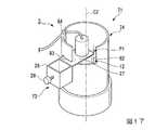
図1から図3に示すように、本実施形態の自動給液システム1は、本実施形態の液面センサ装置51と、液面センサ装置51の水位センサ(液面センサ)12に接続された自動給液装置46と、を備えている。なお、以下の全ての図面は模式的なものであり、自動給液システムの各構成の長さ、幅、及び厚みの比率等は実際のものと同一とは限らず、適宜変更することができる。(First Embodiment)
Hereinafter, the first embodiment of the automatic liquid supply system according to the present invention will be described with reference to FIGS. 1 to 11.
As shown in FIGS. 1 to 3, the automatic
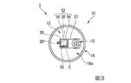
液面センサ装置51は、用水(液体)の液面の位置を検出する前述の水位センサ12と、水位センサ12が取付けられるセンサマウント(センサ取付け部)15と、センサマウント15が設置されるセンサガイド(支持部)52と、センサガイド52に着脱可能な計測部53と、センサガイド52の少なくとも一部、水位センサ12、及びセンサマウント15を収容する収容空間16aが形成された収容パイプ(収容体)16と、を有している。 The liquid
水位センサ12としては、例えば公知のフロート式のセンサを用いることができる。水位センサ12は、図示はしないがシャフトに通されたフロートを有している。用水に浸されたときにフロートが浮かぶことで、シャフトの内部のスイッチ回路がOFF状態からON状態に切り替わる。この例では、液面の位置が水位センサ12の基準位置12aよりも下方から上方に移ったときに、スイッチ回路がOFF状態からON状態に切り替わるとする。一方で、液面の位置が水位センサ12の基準位置12aよりも上方から下方に移ったときに、スイッチ回路がON状態からOFF状態に切り替わるとする。
水位センサ12がOFF状態及びON状態に切り替わることで、水位センサ12の基準位置12aに用水の液面があることが分かる。
ただし、水位センサ12の基準位置12aはこの位置に限定されず、水位センサ12の仕様等に応じて適宜設定される。As the
By switching the
However, the
水位センサ12には、リード線19の第一端部が接続されている。リード線19の長さは、例えば30cmである。リード線19の第二端部には、コネクタ20が設けられている。このコネクタ20及び後述する自動給液装置46のコネクタ48は、防水性を有するコネクタであることが好ましい。 The first end of the
センサガイド52は、図3から5に示すように、例えば棒状であって、長手方向に直交する断面がU字状に形成されている。すなわち、センサガイド52は、背板55と、背板55の各端部から背板55に直交する方向に延びる一対の側板56とを有する。一対の側板56は、対向するように配置されている。センサガイド52は、ステンレス鋼材を折り曲げること等で形成することができる。 As shown in FIGS. 3 to 5, the
図4及び5に示すように、背板55には、センサガイド52の長手方向に延びる一対の貫通孔(接続領域)55a、55bが形成されている。第一貫通孔55a及び第二貫通孔55bは、センサガイド52の長手方向に長い長孔である。貫通孔55a、55bは、長手方向に間隔を空けて形成されている。第一貫通孔55aはセンサガイド52の第二端部に、第二貫通孔55bはセンサガイド52の長手方向の中央部に形成されている。例えば、貫通孔55a、55bの長手方向の長さは、10cmである。
センサガイド52の第一端部には、先細り部52bが形成されている。先細り部52bでは、一対の側板56の幅が第一端部の先端に向かうにしたがって狭くなっている。先細り部52bの先端部のなす角度θは、鋭角である。
センサガイド52に先細り部52bが形成されていることで、後述するようにセンサガイド52の挿し込み作業が容易になる。As shown in FIGS. 4 and 5, the
A tapered
Since the tapered
図1に示すように、センサガイド52は、センサガイド52の長手方向が収容パイプ16の軸線C方向に沿うように配置されている。
センサガイド52には、前述のセンサマウント15が設置される。As shown in FIG. 1, the
The
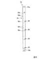
図6に示すように、例えば、計測部53は細長い板状(棒状)であってもよい。計測部53の長手方向の両端部には、係合孔53a、53bが形成されている。計測部53の長手方向の中間部における表面には、目盛り58、及び目盛り58の高さを表す数値59が記載され(設けられ)ている。
目盛り58は、主目盛り58a、及び補助目盛り58b、58cを有している。As shown in FIG. 6, for example, the measuring
The
主目盛り58aは、例えば計測部53の幅方向に延びる比較的長い直線状の溝であり、計測部53の長手方向に例えば5cmおきに記載されている。補助目盛り58b、58cは、計測部53の幅方向に延びる比較的短い直線状の溝であり、計測部53の長手方向に例えば1cmおきに記載されている。
数値59は、鉛直方向の原点である0cmを表す主目盛り58aの位置に「0」と記載されている。数値59は、この0cmを表す主目盛り58aの上方に、例えば5cmおきに「5」、「10」と記載されている。一方で、数値59は、この0cmを表す主目盛り58aの下方に、例えば5cmおきに「−5」、「−10」と記載されている。
目盛り58は、計測部53にプレス加工等により計測部53の長手方向に沿って形成される。目盛り58は、水位センサ12が設置される高さを表す。
計測部53は、センサガイド52とは独立して構成されている。言い換えれば、計測部53は、センサガイド52とは別体である。The
The
The
The
図4に示すように、計測部53は、センサガイド52の背板55の外側の表面に配置される。背板55の内側の表面には、一対の裏金板61が配置される。各裏金板61には、図示しない雌ネジが形成されている。
一対の止めネジ(軸状部材)62は、計測部53の係合孔53a、53bに挿入されることで、計測部53の外面から突出する。一方の止めネジ62は、第一貫通孔55aに挿入されるとともに裏金板61の雌ネジに螺合する。もう一方の止めネジ62は、第二貫通孔55bに挿入されるとともに裏金板61の雌ネジに螺合する。As shown in FIG. 4, the measuring
The pair of set screws (shaft-shaped members) 62 protrude from the outer surface of the measuring
裏金板61に各止めネジ62を締め込んで、裏金板61及び一対の止めネジ62で背板55及び計測部53を挟み込むことで、センサガイド52に計測部53が取付けられる。計測部53は、センサガイド52の長手方向に沿うように取付けられる。
なお、一対の止めネジ62は計測部53に固定されていてもよい。
一方で、裏金板61と止めネジ62との螺合を解除することで、センサガイド52から計測部53が取外される。The
The pair of
On the other hand, the measuring
使用者が、裏金板61と一対の止めネジ62との螺合を緩めた状態で、各止めネジ62が貫通孔55a、55bに挿入される位置をセンサガイド52の長手方向にずらすと、センサガイド52に対して計測部53が長手方向に移動する。この状態で各裏金板61に止めネジ62を締め込んで、移動した計測部53の位置を保持する。
このように、計測部53は、センサガイド52に対する長手方向の相対位置の変更が可能なように構成される。
後述するように計測部53は、計測部53の長手方向が鉛直方向に沿うように配置される。センサガイド52の貫通孔55a、55b、計測部53の係合孔53a、53b、裏金板61、及び止めネジ62で、センサガイド52と計測部53との鉛直方向に沿った相対位置を連続的に変更可能な固定機構63を構成する。When the user loosens the screw between the
In this way, the measuring
As will be described later, the measuring
図1及び図3に示すように、センサマウント15は、角筒状に形成されたマウント本体26と、正面視でL字状に形成され、マウント本体26の外面に固定された係合部27と、マウント本体26に螺合する止めネジ28と、を有している。
マウント本体26は、角筒状の筒孔の内部にセンサガイド52及び計測部53が挿入可能である。
係合部27は、マウント本体26の外面から水平方向に延びるセンサ固定部を備えている。このセンサ固定部に対して水位センサ12が、ネジ等により着脱可能に固定されている。なお、係合部27に水位センサ12を固定する方法は、これに限定されない。
止めネジ28は、マウント本体26の図示しない雌ネジ部に螺合する。マウント本体26に対して止めネジ28を回転させることで、マウント本体26に対する止めネジ28の相対位置が変化する。これにより、マウント本体26の筒孔内に突出する止めネジ28の長さを調節することができる。As shown in FIGS. 1 and 3, the
The
The engaging
The
センサガイド52の長手方向において、水位センサ12の基準位置12aとマウント本体26の下端とが一致していてもよい。このように構成することで、計測部53の目盛り58に水位センサ12の基準位置12aを合わせやすくなる。
また、マウント本体26には、センサガイド52の長手方向における水位センサ12の基準位置12aに対応する位置にスリットや孔等が形成されていてもよい。使用者がスリット等を通して計測部53の目盛り58を視認することで、水位センサ12の基準位置12aを所望の高さに配置することができる。In the longitudinal direction of the
Further, the
このように構成されたセンサマウント15において、使用者は、センサマウント15の係合部27に水位センサ12を取付ける。センサマウント15のマウント本体26の筒孔内に、センサガイド52及び計測部53を挿入する。計測部53の目盛り58に対する水位センサ12の位置を調節する。具体的には、センサガイド52の長手方向において、水位センサ12の基準位置12aを、目盛り58で表示された所望の高さに一致させる。
この状態で止めネジ28を回転させてセンサガイド52に止めネジ28を押し付け、センサガイド52にマウント本体26を固定する。In the
In this state, the
以上の工程を行うことで、計測部53の目盛り58の所望の位置に水位センサ12を固定することができる。
なお、この状態においても、固定機構63の止めネジ62を緩めることで、センサガイド52に対して計測部53を長手方向に移動させることができる。
目盛り58に対する水位センサ12の位置を調節するには、センサガイド52から止めネジ28が離間するように止めネジ28を回転させ、センサガイド52に対するマウント本体26の固定を解除する。その後、センサガイド52に対してマウント本体26をセンサガイド52の長手方向に沿って移動させる。再び止めネジ28を回転させて、センサガイド52に止めネジ28を押し付け、センサガイド52にマウント本体26を固定する。By performing the above steps, the
Even in this state, the measuring
To adjust the position of the
図1及び図3に示すように、収容パイプ16は、塩化ビニル等の樹脂や金属により円筒状に形成されている。なお、収容パイプ16の軸線Cに直交する断面における縁部の形状は、円形に限られず、楕円形、多角形等でもよい。
収容パイプ16の筒孔が、前述の収容空間16aである。収容パイプ16の軸線C方向の第一端部16bには、開口31が形成されている。
収容パイプ16の軸線C方向の第一端部16bである地面差込み部には、収容パイプ16の側面16dから収容空間16aに達する第一切欠き32が形成されている。第一切欠き32は、収容パイプ16の軸線C方向の端面から軸線C方向に所定の長さ延びている。第一切欠き32は、収容パイプ16の周方向に半周以上にわたって形成されている。
第一切欠き32を形成することで収容パイプ16の第一端部16bに形成される突部33は、収容パイプ16の周方向の一部に形成されている。As shown in FIGS. 1 and 3, the
The tubular hole of the
A
The
図1及び図2に示すように、収容パイプ16の軸線C方向の第二端部16cには、開口35が形成されている。収容パイプ16の第二端部16cには、収容パイプ16の側面16dから収容空間16aに達する第二切欠き36が形成されている。第二切欠き36は、収容パイプ16の軸線C方向の端面から軸線C方向に所定の長さ延びている。第二切欠き36の幅は、自動給液装置46の後述するリード線47の外径程度である。
収容パイプ16の側面16dには、収容パイプ16を貫通する複数の第二連通孔(連通孔)37が形成されている。各第二連通孔37は、収容パイプ16の外部と収容空間16a(内部)との間で用水を流通させる。複数の第二連通孔37は、収容パイプ16の軸線C周りに互いに間隔を空けて形成されている。複数の第二連通孔37は、収容パイプ16の軸線C方向に互いに間隔を空けて形成されている。As shown in FIGS. 1 and 2, an
A plurality of second communication holes (communication holes) 37 penetrating the
本実施形態の液面センサ装置51は、第二蓋部40を備える。第二蓋部40は、収容パイプ16の第二端部16cに着脱可能に取付けられ、収容パイプ16の開口35を覆う。第二蓋部40は、円板状の蓋本体41と、蓋本体41の縁部に蓋本体41の全周にわたり立設された外縁部42とを有している。外縁部42の内径は、収容パイプ16の外径よりも大きい。図2に示すように、外縁部42の軸線C方向の長さL1は、第二切欠き36の軸線C方向の長さL2よりも短い。このため、第二切欠き36の一部は、収容パイプ16に第二蓋部40を取付けたときに第二蓋部40に覆われない。第二蓋部40から第二蓋部40の外部に露出した第二切欠き36の一部により、通し部36aが形成される。 The liquid
自動給液装置46は公知の構成のものであり、図示しない給水ポンプや制御部等を備えている。制御部には、図1に示すリード線47の第一端部が接続されている。リード線47は、収容パイプ16の通し部36aを通る。
リード線47の第二端部には、コネクタ48が設けられている。コネクタ48は、水位センサ12に接続されたコネクタ20に着脱可能である。
制御部は、水位センサ12がOFF状態であるときには、給水ポンプを駆動して用水を供給する。一方で、制御部は、水位センサ12がON状態であるときには、給水ポンプを停止させる。このように、制御部は、水位センサ12の検出結果に基づいて用水を水田等の被供給体に供給する。The automatic
A
When the
次に、以上のように構成された自動給液システム1を水田の平坦な地盤に設置する手順について説明する。
予め、センサガイド52の長手方向における所定の位置に固定機構63により計測部53を取付けておく。
まず、図7に示すように、使用者はセンサガイド52及び計測部53にセンサマウント15を取付け、センサマウント15の係合部27に水位センサ12を取付ける。
次に、水田Fの地盤(被設置体)F1にセンサガイド52の第一端部を挿し込む(挿入する)。センサガイド52は棒状に形成され、しかもセンサガイド52の第一端部には先細り部52bが形成されているため、地盤F1にセンサガイド52の第一端部を容易に挿し込むことができる。
なお、地盤F1にセンサガイド52を取付けてから、このセンサガイド52にセンサマウント15及び水位センサ12を取付けてもよい。Next, the procedure for installing the automatic
The measuring
First, as shown in FIG. 7, the user attaches the
Next, the first end portion of the
After attaching the
地盤F1にセンサガイド52を挿し込むときに、センサガイド52の長手方向が鉛直方向に平行になるようにする。さらに、図1に示すように、目盛り58の「0」の数値59が記載された主目盛り58aが、地盤F1の表面に一致するようにする。この場合、地盤F1の表面から用水の液面までの高さと、目盛り58による高さの表示とが一致する。 When the
次に、止めネジ28を回転させて、センサガイド52から止めネジ28を離間させる。センサガイド52に対してマウント本体26をセンサガイド52の長手方向に移動させ、計測部53の目盛り58に対する水位センサ12の位置を調節する。目盛り13は水位センサ12が設置される高さを表すため、使用者は地盤F1の表面から水位センサ12までの高さが容易にわかる。
例えば、センサガイド52の長手方向における水位センサ12の基準位置12aを8.5cmに対応する補助目盛り58cに合わせる。
この状態で止めネジ28を回転させてセンサガイド14に止めネジ28を押し付け、センサガイド52にマウント本体26を固定する。Next, the
For example, the
In this state, the
なお、地盤F1の表面に一致させる目盛りは、「0」の数値59が記載された主目盛り58aに限定されず、他の主目盛り58aや補助目盛り58b、58c等でもよい。この場合には、使用者は、「0」の数値59が記載された主目盛り58aに対する地盤F1の表面に一致させた他の主目盛り58a等の位置を補正値として記憶する。この補正値を考慮して、センサガイド52の長手方向における水位センサ12の基準位置12aを、所望の目盛り58に合わせる。
例えば、2cmを表す補助目盛り58bを地盤F1の表面に一致させたときに、地盤F1の表面から5cmの高さに水位センサ12の基準位置12aを配置する場合について説明する。この場合には補正値は2cmとなり、所望の水位センサ12の高さである5cmに補正値の2cmを加えた7cmに対応する補助目盛り58bに水位センサ12の基準位置12aを合わせる。The scale to match the surface of the ground F1 is not limited to the
For example, a case where the
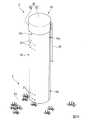
次に、図8に示すように、センサガイド52の少なくとも一部、水位センサ12、及びセンサマウント15を囲うように収容パイプ16を配置する。地盤F1に収容パイプ16の突部33を挿し込む。このとき、センサガイド52の少なくとも一部、水位センサ12、及びセンサマウント15が、収容パイプ16の収容空間16a内に収容される。泥土等の付着物が、収容パイプ16の第一端部16bの収容空間16a内に入る。地盤F1に収容パイプ16を挿し込んだときに、収容パイプ16の開口31の全体が地盤F1により塞がれる。
収容パイプ16が円柱状ではなく中空の円筒状に形成されているため、収容パイプ16を軸線C方向に沿って地盤F1に挿し込むことにより、地盤F1から受ける抵抗を抑えて挿し込みやすくなる。Next, as shown in FIG. 8, the
Since the
後述するように水位センサ12の高さを変更するときには、地盤F1から収容パイプ16を抜き取る。このため、地盤F1に収容パイプ16を挿し込む深さは、地盤F1にセンサガイド52を挿し込む深さに比べて例えば70mmほど短い。
使用者は、自動給液装置46のコネクタ48と水位センサ12のコネクタ20とを接続する。収容パイプ16の第二切欠き36に、自動給液装置46のリード線47を通す。When changing the height of the
The user connects the
次に、図9に示すように、収容パイプ16の第二端部16cに第二蓋部40を取付ける。収容パイプ16に第二蓋部40を取付けることで、ゴミ等の異物が収容パイプ16内に入りにくくなる。
このとき、第二切欠き36には第二蓋部40から露出した通し部36aが形成されるため、第二切欠き36の通し部36aからリード線47が収容パイプ16の外部に引き出される。
以上の工程により、水田Fの平坦な地盤F1に自動給液システム1が設置される。Next, as shown in FIG. 9, the
At this time, since the through
Through the above steps, the automatic
次に、自動給液システム1を水田Fの凹んだ地盤F1に設置する手順について説明する。
まず、図10に示すように、地盤F1に凹部F2を形成する。凹部F2の底面にセンサガイド52の第一端部を挿し込む。このとき、センサガイド52の長手方向が鉛直方向に平行になるようにする。目盛り58の「0」の数値59が記載された主目盛り58aが、地盤F1の凹部F2以外の表面に一致するようにする。センサガイド52の長手方向において、水位センサ12の基準位置12aを、例えば−5cmに対応する主目盛り58aに合わせる。センサガイド52にセンサマウント15及び水位センサ12を固定する。
凹部F2の底面に収容パイプ16を挿し込み、収容パイプ16でセンサガイド52等を囲う。自動給液装置46のコネクタ48及びリード線47を前述のように処理し、収容パイプ16に第二蓋部40を取付ける。
以上の工程により、凹部F2の底面に自動給液システム1が設置される。Next, a procedure for installing the automatic
First, as shown in FIG. 10, a recess F2 is formed in the ground F1. The first end of the
The
Through the above steps, the automatic
このように自動給液システム1を設置すると、地盤F1の凹部F2以外の表面から5cm下方の位置に用水の液面の高さが保たれる。 When the automatic
次に、水位センサ12の高さを変更する手順について説明する。
まず、使用者は、収容パイプ16から第二蓋部40を取外す。収容パイプ16の第二切欠き36から自動給液装置46のリード線47を外す。自動給液装置46のコネクタ48と水位センサ12のコネクタ20との接続を解除する。
地盤F1から収容パイプ16を抜き取る。収容パイプ16の第一端部16bから収容空間16a内に入った泥土等の付着物は、第一端部16bに第一切欠き32が形成されていることで、収容空間16a内に保持されにくくなる。したがって、地盤F1から収容パイプ16を抜き取るときに収容パイプ16の第一端部16bに付着物が残ったまま収容パイプ16が持ち上げられるのが抑えられる。Next, the procedure for changing the height of the
First, the user removes the
The
次に、センサガイド52から止めネジ28が離間するように止めネジ28を回転させ、センサガイド52に対してマウント本体26をセンサガイド52の長手方向に沿って移動させる。センサガイド52の長手方向における水位センサ12の基準位置12aを、新たな所望の目盛り58に合わせる。
再び止めネジ28を回転させて、センサガイド52に止めネジ28を押し付け、センサガイド52に水位センサ12を固定する。
地盤F1に収容パイプ16を挿し込み、収容パイプ16でセンサガイド52等を囲う。自動給液装置46のコネクタ48及びリード線47を前述のように処理し、収容パイプ16に第二蓋部40を取付ける。
以上の工程により、水位センサ12の高さが変更される。Next, the
The
The
By the above steps, the height of the
次に、自動給液システム1の動作について説明する。
例えば、図1及び図2に示すように、用水の液面の位置L6が水位センサ12の基準位置12aを合わせた8.5cmに対応する補助目盛り58cよりも下方である場合で説明する。
この場合、用水は、収容パイプ16の第二連通孔37を通って収容パイプ16の収容空間16a内に浸入する。用水の水面に枯れ草等の浮遊物F6が浮かんでいる場合がある。この場合でも、複数の第二連通孔37が軸線C周りに互いに間隔を空けて形成されていることで、複数の第二連通孔37の一部が浮遊物F6により詰まっても、残部の全てが詰まる可能性は小さい。したがって、複数の第二連通孔37が完全には詰まりにくくなる。
また、複数の第二連通孔37が軸線C方向に互いに間隔を空けて形成されていることで、液面の軸線C方向の位置によらず、第二連通孔37を通して収容空間16a内に用水が浸入しやすくなる。
収容パイプ16の収容空間16a内にセンサガイド52の少なくとも一部、水位センサ12、及びセンサマウント15が収容されているため、風雨等により水位センサ12が破損したり、センサガイド52に対して水位センサ12が位置ずれしたりしにくくなる。Next, the operation of the automatic
For example, as shown in FIGS. 1 and 2, the case where the position L6 of the liquid level of the irrigation water is lower than the
In this case, the irrigation water enters the
Further, since the plurality of second communication holes 37 are formed at intervals in the axis C direction, water is supplied into the
Since at least a part of the
用水の液面の位置L6が水位センサ12の基準位置12aよりも下方であるので、水位センサ12はOFF状態になる。制御部は、給水ポンプを駆動して用水を水田Fに供給する。用水が水田Fに供給されると、用水の液面の位置L6が上昇する。
図1に示すように、用水の液面の位置L7が8.5cmに対応する補助目盛り58cに達すると、水位センサ12はON状態になる。制御部は、給水ポンプを停止させる。Since the position L6 of the liquid level of the irrigation water is lower than the
As shown in FIG. 1, when the position L7 of the liquid level of the irrigation water reaches the
給水ポンプが停止してから一定の時間が経過すると、用水が蒸発する等して用水の液面の位置L7が下降する。水位センサ12はOFF状態になり、制御部は給水ポンプを駆動して用水を水田Fに供給する。
このように、水位センサ12が用水の液面の位置を検出し、水位センサ12の検出結果に基づいて自動給液装置46が水田Fに用水を供給することで、地盤F1の表面から用水の液面までの高さが約8.5cmに保たれる。When a certain time elapses after the water supply pump is stopped, the position L7 of the liquid level of the water is lowered due to evaporation of the water. The
In this way, the
次に、複数の自動給液システム1を水田の平坦な地盤F1に設置する手順について説明する。
この例では、図11に示すように、地盤F1に自動給液システム1を複数(以下、自動給液システム1A、1Bと呼ぶ)設置する場合で説明する。自動給液システム1Aの構成については、各構成の符号に英大文字「A」を付加することで示す。同様に、自動給液システム1Bの構成については、各構成の符号に英大文字「B」を付加することで示す。
使用者は、各センサガイド52A、52Bにセンサマウント15A、15B及び水位センサ12A、12Bを取付ける。水田Fの地盤F1にセンサガイド52A、52Bの第一端部を挿し込む。センサガイド52A、52Bは、長手方向が鉛直方向に平行になるように挿し込む。
このとき、地盤F1の硬さが場所により異なること等により、センサガイド52Aよりもセンサガイド52Bの方が深く挿し込まれたとする。Next, a procedure for installing a plurality of automatic
In this example, as shown in FIG. 11, a case where a plurality of automatic liquid supply systems 1 (hereinafter referred to as automatic
The user attaches the sensor mounts 15A and 15B and the
At this time, it is assumed that the
地盤F1に挿し込んだセンサガイド52A、52Bの位置は変えずに、センサガイド52A、52Bに対して計測部53A、53Bを長手方向に移動させて、計測部53A、53Bの目盛り58A、58Bの設置基準である高さを統一する。具体的には、平坦な地盤F1の表面に、計測部53A、53Bの目盛り58A、58Bの「0」の数値59A、59Bが記載された主目盛り58aA、58aB(以下、零点と呼ぶ)等の高さを合せる。
なお、用水の液面の位置等に計測部53A、53Bの零点等の高さを合せてもよい。
このように、センサガイド52A、52Bに対して計測部53A、53Bを長手方向に移動させることで、自動給液システム1A、1Bを設置する位置によらず、計測部53A、53Bの目盛り58A、58Bの零点の高さが揃う。Without changing the positions of the sensor guides 52A and 52B inserted into the ground F1, the measuring
The height of the zero points of the measuring
By moving the measuring
以下、自動給液システム1A、1Bに対して行う手順は、前述の手順と同様なので説明を省略する。 Hereinafter, the procedure performed for the automatic
以上説明したように、本実施形態の液面センサ装置51によれば、使用者は、地盤F1にセンサガイド52を設置する。センサガイド52に取付けられた計測部53に目盛り58が記載されているため、地盤F1の表面から水位センサ12までの高さを容易に認識することができる。
また、基準となる計測部53の位置をセンサガイド52に対して調節できるため、地盤F1の硬さ等の性質に影響されず、地盤F1の表面等の同一の高さの基準を目盛り58の零点として定められる。したがって、地盤F1に液面センサ装置51を複数設置した場合に、計測部53の高さの設置基準を統一することができる。As described above, according to the liquid
Further, since the position of the
液面センサ装置51が収容パイプ16を備えることで、風雨等により水位センサ12が破損したり、センサガイド52に対して水位センサ12が位置ずれしたりしにくくすることができる。ごみ等による水位センサ12の精度の低下を防ぐことができる。
収容パイプ16は筒状に形成されている。そして、センサガイド52は棒状に形成され、センサガイド52は、センサガイド52の長手方向が収容パイプ16の軸線C方向に沿うように配置されている。収容パイプ16は筒状であってセンサガイド52は棒状であるため、地盤F1に収容パイプ16及びセンサガイド52を軸線C方向に挿し込みやすくすることができる。When the liquid
The
収容パイプ16の第一端部16bの収容空間16a内に入った泥土等の付着物は、第一端部16bに第一切欠き32が形成されていることで、収容空間16a内に保持されにくくなる。したがって、地盤F1から収容パイプ16を抜き取るときに収容パイプ16の第一端部16bに泥土等が残ったまま収容パイプ16が持ち上げられるのを抑えることができる。
液面センサ装置51が第二蓋部40を備えることで、ゴミ等の異物を収容パイプ16内に入りにくくすることができる。
第二蓋部40から露出した通し部36aがある第二切欠き36が形成されていることで、通し部36aから自動給液装置46のリード線47を収容パイプ16の外部に引き出すことができる。Adhesions such as mud that have entered the
When the liquid
Since the
液面センサ装置51が固定機構63を備えることで、センサガイド52と計測部53との鉛直方向(センサガイド52の長手方向)に沿った相対位置を連続的に変更することができる。固定機構63を構成するセンサガイド52の貫通孔55a、55b、計測部53の係合孔53a、53b、裏金板61、及び止めネジ62という簡単な構成で、センサガイド52に対して計測部53を鉛直方向に沿って移動させることができる。
計測部53の表面に数値59が記載されていることで、使用者は目盛り58の高さの値を容易に認識することができる。When the liquid
Since the
複数の第二連通孔37が軸線C周りに互いに間隔を空けて形成されているため、用水の液面に浮かんだ浮遊物F6等により複数の第二連通孔37の一部が詰まっても、複数の第二連通孔37の残部の全てが詰まる可能性は小さい。したがって、複数の第二連通孔37の残部により用水を通すことができる。
また、本実施形態の自動給液システム1によれば、使用者が地盤F1の表面から水位センサ12までの高さを容易に認識することができると同時に、複数設置した場合の計測部53の高さの設置基準を統一することができる液面センサ装置51を用いて、自動給液装置46を安定的に制御することができる。Since the plurality of second communication holes 37 are formed around the axis C at intervals from each other, even if a part of the plurality of second communication holes 37 is clogged by floating matter F6 or the like floating on the liquid surface of the irrigation water. It is unlikely that all of the rest of the plurality of second communication holes 37 will be clogged. Therefore, the irrigation water can be passed through the remaining portions of the plurality of second communication holes 37.
Further, according to the automatic
なお、本実施形態では、接続領域は貫通孔55a、55bであるとした。しかし、接続領域はこれに限定されず、背板55に形成される切欠き等であってもよい。
計測部53に数値59が記載されていなくてもよい。数値59が記載されていなくても、使用者は目盛り58が意味する高さを認識することができるからである。
固定機構63が、センサガイド52の貫通孔55a、55b、計測部53の係合孔53a、53b、裏金板61、及び止めネジ62で構成されるとした。しかし、固定機構はこれに限定されない。固定機構は、センサガイド52及び計測部53のそれぞれに固定され、互いに着脱可能な磁石や面ファスナーでもよい。固定機構は、センサガイド52及び計測部53の一方に固定され、他方に着脱可能な接着テープでもよい。
センサマウント15は、センサガイド52に固定されていてもよい。この場合、センサガイド52に設置される水位センサ12をセンサガイド52の長手方向に移動させることができなくなる。In this embodiment, the connection regions are through
The
It is assumed that the fixing mechanism 63 is composed of through
The
(第2実施形態)
次に、本発明の第2実施形態について図12から19を参照しながら説明するが、前記実施形態と同一の部位には同一の符号を付してその説明は省略し、異なる点についてのみ説明する。
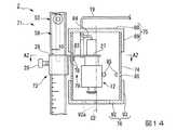
図12及び13に示すように、本実施形態の自動給液システム2は、第1実施形態の自動給液システム1の液面センサ装置51に代えて、本実施形態の液面センサ装置71を備えている。
液面センサ装置71は、液面センサ装置51のセンサマウント15、収容パイプ16、及び第二蓋部40に代えて、センサマウント73、収容パイプ74、第二蓋部75、及び第一蓋部76を備えている。(Second Embodiment)
Next, the second embodiment of the present invention will be described with reference to FIGS. 12 to 19, but the same parts as those in the embodiment are designated by the same reference numerals, the description thereof will be omitted, and only the differences will be described. To do.
As shown in FIGS. 12 and 13, the automatic
The liquid
図14及び15に示すように、センサマウント73は、センサマウント15の各構成に加えて、センサマウント15のセンサ固定部から下方に向かって延びる一対の狭持片78を有している。一対の狭持片78は、補助固定部79を構成する。一対の狭持片78は、マウント本体26からセンサ固定部が延びる方向に間隔を空けて配置されている。後述するように、補助固定部79は、センサマウント73に収容パイプ74を取付けるためのものである。 As shown in FIGS. 14 and 15, in addition to each configuration of the
図16に示すように、収容パイプ74は、塩化ビニル等の樹脂や金属により円筒状に形成されている。収容パイプ74の上端部となる軸線C2方向の第二端部には、収容パイプ74の側面から収容パイプ74の収容空間に達する案内切欠き82が形成されている。案内切欠き82は、収容パイプ74の第二端部の端面から軸線C2方向に所定の長さ延びている。案内切欠き82の幅は、センサマウント73の係合部27の幅よりも長い。
なお、例えば、本実施形態で用いられる水位センサ12に接続されるリード線19の長さは、35cmである。
収容パイプ74には、案内切欠き82の底面から収容パイプ74の周方向に延びる固定切欠き(固定部)83が形成されている。固定切欠き83は、収容パイプ74の側面から収容パイプ74の収容空間に達する。固定切欠き83は、案内切欠き82に接続されている。As shown in FIG. 16, the
For example, the length of the
The
収容パイプ74の第二端部には、前述の第二切欠き36と同様に第二切欠き84が形成されている。第二切欠き84は、案内切欠き82とは周方向に位置をずらして配置されている。第二切欠き84は、収容パイプ74の第二端部の端面から軸線C2方向に所定の長さ延びている。第二切欠き84の幅は、コネクタ20に接続されたリード線19の外径程度である。
なお、収容パイプ74の第一端部に、第二切欠き84と同様の切欠きが形成されてもよい。
図14に示すように、収容パイプ74には、収容パイプ74の外部と内部とをつなぐ第二連通孔85が形成されている。この例では、第二連通孔85は、収容パイプ74の軸線C2周りに間隔を空けて複数形成されている。A
A notch similar to the
As shown in FIG. 14, the
ここで、このように構成された収容パイプ74にセンサマウント73を取付ける手順について説明する。センサマウント73には、予め水位センサ12が固定されているものとする。
図17に示すように、収容パイプ74の収容空間に水位センサ12を配置するとともに、収容パイプ74の案内切欠き82内の位置P1にセンサマウント73の係合部27を配置する。収容パイプ74における案内切欠き82の縁部が、補助固定部79の一対の狭持片78により挟み込まれる。収容パイプ74に対してセンサマウント73を軸線C2周りの一方に回転させて、収容パイプ74の固定切欠き83内にセンサマウント73の係合部27を配置する。これにより、収容パイプ74にセンサマウント73が取付けられる。このように、固定切欠き83及び補助固定部79は、センサマウント73を収容パイプ74に固定する。Here, a procedure for attaching the
As shown in FIG. 17, the
図12に示すように、センサガイド52にセンサマウント73を固定すると、収容パイプ74は、軸線C2がセンサガイド52の長手方向に沿うように配置される。
収容パイプ74は、センサマウント73の一部及び水位センサ12を収容する。収容パイプ74は、センサマウント73を介してセンサガイド52に着脱可能である。As shown in FIG. 12, when the
The
一方で、収容パイプ74からセンサマウント73が取外すには、収容パイプ74に対してセンサマウント73を軸線C2周りの他方に回転させる。収容パイプ74の案内切欠き82内から、センサマウント73を取外す。 On the other hand, in order to remove the
図14に示すように、第二蓋部75は、前述の第二蓋部40とは大きさのみが異なる。第二蓋部75は、円板状の蓋本体88と、蓋本体88の縁部にの蓋本体88の全周にわたり立設された外縁部89とを有している。外縁部89の内径は、収容パイプ74の外径よりも大きい。第二蓋部75は、収容パイプ74の第二端部に着脱可能に取付けられる。第二蓋部75は、収容パイプ74の第二端部に形成された開口を覆う。 As shown in FIG. 14, the
図14及び18に示すように、第一蓋部76は、円板状の蓋本体92と、蓋本体92の縁部に蓋本体92の全周にわたり立設された外縁部93とを有している。蓋本体92には、収容パイプ74の外部と内部とをつなぐ第一連通孔92aが形成されている。
外縁部93の内径は、収容パイプ74の外径よりも大きい。第一蓋部76は、収容パイプ74の第一端部に着脱可能に取付けられる。第一蓋部76は、収容パイプ74の第一端部に形成された開口を覆う。As shown in FIGS. 14 and 18, the
The inner diameter of the
この例では、収容パイプ74の第二切欠き84に水位センサ12のリード線19が通されている。
図12に示すように、自動給液装置46、及び互いに接続されたコネクタ20、48は、ケーシング96に収容されている。In this example, the
As shown in FIG. 12, the automatic
次に、以上のように構成された自動給液システム2を地盤F1の凹部F2に設置する手順について説明する。
まず、使用者は、図19に示すように、センサガイド52にセンサマウント73及び水位センサ12を取付ける。収容パイプ74で水位センサ12等を囲う。前述のように、センサマウント73に収容パイプ74を取付ける。収容パイプ74の第二切欠き84に、水位センサ12のリード線19を通す。収容パイプ74に、第一蓋部76及び第二蓋部75を取付ける。
地盤F1に形成した凹部F2の底面にセンサガイド52の第一端部を挿し込む。自動給液装置46のコネクタ48と水位センサ12のコネクタ20とを接続する。互いに接続したコネクタ20、48、及び自動給液装置46をケーシング96に収容する。
以上の工程により、凹部F2の底面に自動給液システム2が設置される。
用水は、第一蓋部76の第一連通孔92a及び収容パイプ74の第二連通孔85を通って、収容パイプ74の収容空間内に浸入したり、収容パイプ74から外部に流れ出たりする。Next, a procedure for installing the automatic
First, as shown in FIG. 19, the user attaches the
The first end of the
Through the above steps, the automatic
The irrigation water enters the accommodation space of the
なお、水位センサ12の位置を調節するときには、収容パイプ74内に水位センサ12を収容したまま、センサガイド52に対してセンサマウント73を鉛直方向に移動させてもよい。 When adjusting the position of the
以上説明したように、本実施形態の液面センサ装置71によれば、使用者が地盤F1の凹部F2の底面から水位センサ12までの高さを容易に認識することができる。
液面センサ装置71が収容パイプ74を備えることで、風雨等により水位センサ12が破損するのを防いだり、ごみ等による水位センサ12の精度の低下を防いだりすることができる。
液面センサ装置71が第一蓋部76を備えることで、収容パイプ74内にゴミ等の異物を入りにくくすることができる。As described above, according to the liquid
When the liquid
When the liquid
以上、本発明の第1実施形態及び第2実施形態について図面を参照して詳述したが、具体的な構成はこの実施形態に限られるものではなく、本発明の要旨を逸脱しない範囲の構成の変更、組み合わせ、削除等も含まれる。さらに、各実施形態で示した構成のそれぞれを適宜組み合わせて利用できることは、言うまでもない。
例えば、前記第1実施形態及び第2実施形態では、収容パイプに形成される第二連通孔の数は、複数でなく1つでもよい。Although the first embodiment and the second embodiment of the present invention have been described in detail with reference to the drawings, the specific configuration is not limited to this embodiment, and the configuration does not deviate from the gist of the present invention. Changes, combinations, deletions, etc. of are also included. Further, it goes without saying that each of the configurations shown in each embodiment can be used in combination as appropriate.
For example, in the first embodiment and the second embodiment, the number of the second communication holes formed in the accommodating pipe may be one instead of a plurality.
収容パイプ16の第二切欠き36の通し部36aが第二蓋部40から露出するとしたが、第二切欠き36に重なるように第二蓋部40の外縁部42に切欠きが形成されること等により、第二切欠き36の全体が第二蓋部40から露出するように構成してもよい。第2実施形態についても、同様である。
液面センサ装置を設置する場所の周囲にゴミ等が少ない場合等には、液面センサ装置は蓋部を備えなくてもよい。
収容パイプ16の第一端部16bに泥土等が付着しても問題がない場合には、収容パイプ16に第一切欠き32が形成されなくてもよい。
収容体は筒状に形成されているとしたが、収容体は球殻状や箱状等に形成されていてもよい。It is assumed that the through
When there is little dust or the like around the place where the liquid level sensor device is installed, the liquid level sensor device does not have to be provided with a lid.
If there is no problem even if mud or the like adheres to the
Although the container is said to be formed in a tubular shape, the container may be formed in a spherical shell shape, a box shape, or the like.
液面センサ装置に作用する風雨等の影響が充分小さいことが分かっている場合等には、液面センサ装置は収容パイプを備えなくてもよい。
液体は用水に限られず、水、純水、水溶液やブライン等でもよい。
自動給液装置46による給液方法は給水ポンプの駆動に限らず、給水バルブの開閉等であってもよい。When it is known that the influence of wind and rain acting on the liquid level sensor device is sufficiently small, the liquid level sensor device may not be provided with the accommodating pipe.
The liquid is not limited to water, but may be water, pure water, an aqueous solution, brine, or the like.
The liquid supply method by the automatic
1、2 自動給液システム
51、71 液面センサ装置
12 水位センサ(液面センサ)
58 目盛り
52 センサガイド(支持部)
15、73 センサマウント(センサ取付け部)
16、74 収容パイプ(収容体)
16b 第一端部
16c 第二端部
32 第一切欠き
36 第二切欠き
37、85 第二連通孔(連通孔)
40、75 第二蓋部
46 自動給液装置
53 計測部
59 数値
63 固定機構
76 第一蓋部
92a 第一連通孔
C、C2 軸線1, 2 Automatic
58
15,73 Sensor mount (sensor mounting part)
16, 74 Containment pipe (containment body)
16b
40, 75
Claims (10)
Translated fromJapanese前記液面センサが取付けられるセンサ取付け部と、
前記センサ取付け部が設置される支持部と、
前記液面センサが設置される高さを表す目盛りが表面に記載されるとともに、前記支持部に着脱可能な計測部と、
前記支持部と前記計測部との鉛直方向に沿った相対位置を連続的に変更可能な固定機構と、
を備え、
前記計測部は、前記支持部とは独立して構成され、前記支持部に対する相対位置の変更が可能なように構成されていることを特徴とする液面センサ装置。A liquid level sensor that detects the position of the liquid level and
The sensor mounting part to which the liquid level sensor is mounted and
The support part on which the sensor mounting part is installed and the support part
A scale indicating the height at which the liquid level sensor is installed is written on the surface, and a measuring unit that can be attached to and detached from the support unit and a measuring unit that can be attached to and detached from the support unit.
A fixing mechanism that can continuously change the relative position of the support unit and the measurement unit along the vertical direction,
With
The liquid level sensor device is characterized in that the measuring unit is configured independently of the support unit and is configured so that the position relative to the support unit can be changed.
前記支持部は、棒状であり、長手方向が前記収容体の軸線方向に沿うように配置されていることを特徴とする請求項2又は3に記載の液面センサ装置。The housing is tubular and has a tubular shape.
The liquid level sensor device according to claim 2 or 3, wherein the support portion has a rod shape and is arranged so that the longitudinal direction is along the axial direction of the housing.
前記計測部の表面に前記目盛りの高さを表す数値が記載されていることを特徴とする請求項1から8のいずれか一項に記載の液面センサ装置。The measuring unit has a rod shape.
The liquid level sensor device according to any one of claims 1 to8 , wherein a numerical value representing the height of the scale is described on the surface of the measuring unit.
前記液面センサ装置の前記液面センサに接続され、前記液面センサの検出結果に基づいて前記液体を供給する自動給液装置と、
を備えることを特徴とする自動給液システム。The liquid level sensor device according to any one of claims 1 to9 .
An automatic liquid supply device connected to the liquid level sensor of the liquid level sensor device and supplying the liquid based on the detection result of the liquid level sensor.
An automatic liquid supply system characterized by being equipped with.
Applications Claiming Priority (2)
| Application Number | Priority Date | Filing Date | Title |
|---|---|---|---|
| JP2016100111 | 2016-05-19 | ||
| JP2016100111 | 2016-05-19 |
Related Child Applications (1)
| Application Number | Title | Priority Date | Filing Date |
|---|---|---|---|
| JP2019194634ADivisionJP6698928B2 (en) | 2016-05-19 | 2019-10-25 | Liquid level sensor device and automatic liquid supply system |
Publications (2)
| Publication Number | Publication Date |
|---|---|
| JP2017211360A JP2017211360A (en) | 2017-11-30 |
| JP6798868B2true JP6798868B2 (en) | 2020-12-09 |
Family
ID=60475453
Family Applications (3)
| Application Number | Title | Priority Date | Filing Date |
|---|---|---|---|
| JP2016243748AActiveJP6798869B2 (en) | 2016-05-19 | 2016-12-15 | Liquid level sensor device and automatic liquid supply system |
| JP2016243745AActiveJP6798868B2 (en) | 2016-05-19 | 2016-12-15 | Liquid level sensor device and automatic liquid supply system |
| JP2019194634AActiveJP6698928B2 (en) | 2016-05-19 | 2019-10-25 | Liquid level sensor device and automatic liquid supply system |
Family Applications Before (1)
| Application Number | Title | Priority Date | Filing Date |
|---|---|---|---|
| JP2016243748AActiveJP6798869B2 (en) | 2016-05-19 | 2016-12-15 | Liquid level sensor device and automatic liquid supply system |
Family Applications After (1)
| Application Number | Title | Priority Date | Filing Date |
|---|---|---|---|
| JP2019194634AActiveJP6698928B2 (en) | 2016-05-19 | 2019-10-25 | Liquid level sensor device and automatic liquid supply system |
Country Status (1)
| Country | Link |
|---|---|
| JP (3) | JP6798869B2 (en) |
Families Citing this family (6)
| Publication number | Priority date | Publication date | Assignee | Title |
|---|---|---|---|---|
| JP7262770B2 (en)* | 2019-09-30 | 2023-04-24 | 株式会社ほくつう | Surface position display device |
| CN111780830B (en)* | 2020-07-24 | 2021-05-14 | 袁米农业科技有限公司 | Rice field water meter and rice field water level control method |
| CN112178382B (en)* | 2020-09-27 | 2022-03-04 | 广州中工水务信息科技有限公司 | Sealing and locking device for water level sensor and cable connector |
| JP7646188B2 (en)* | 2021-03-25 | 2025-03-17 | 株式会社ほくつう | Field sensor system and field management system |
| JP7437349B2 (en)* | 2021-05-12 | 2024-02-22 | 株式会社クボタケミックス | Field water management system, terminal device and field water management device |
| JP7572931B2 (en) | 2021-10-11 | 2024-10-24 | 株式会社クボタケミックス | Water level sensor installation structure |
Family Cites Families (8)
| Publication number | Priority date | Publication date | Assignee | Title |
|---|---|---|---|---|
| US4187503A (en)* | 1978-09-05 | 1980-02-05 | Walton Robert G | Sump alarm device |
| JP2898700B2 (en)* | 1990-05-17 | 1999-06-02 | カヤバ工業株式会社 | Float switch support structure |
| JPH0622927U (en)* | 1990-12-03 | 1994-03-25 | 日本車輌製造株式会社 | Liquid level detector |
| US5146784A (en)* | 1991-03-04 | 1992-09-15 | Vista Research, Inc. | Sensor for measuring liquid-level changes in storage tanks |
| JPH0645212Y2 (en)* | 1991-11-14 | 1994-11-16 | 宮入商事株式会社 | Liquid level gauge for high pressure liquefied gas |
| JP2659347B2 (en)* | 1995-04-03 | 1997-09-30 | シーケーディ株式会社 | Water level sensor |
| JP2007046489A (en)* | 2005-08-08 | 2007-02-22 | Shin Meiwa Ind Co Ltd | underwater pump |
| JP5098308B2 (en)* | 2006-11-27 | 2012-12-12 | 旭有機材工業株式会社 | Automatic water supply device |
- 2016
- 2016-12-15JPJP2016243748Apatent/JP6798869B2/enactiveActive
- 2016-12-15JPJP2016243745Apatent/JP6798868B2/enactiveActive
- 2019
- 2019-10-25JPJP2019194634Apatent/JP6698928B2/enactiveActive
Also Published As
| Publication number | Publication date |
|---|---|
| JP6698928B2 (en) | 2020-05-27 |
| JP2020076768A (en) | 2020-05-21 |
| JP2017211361A (en) | 2017-11-30 |
| JP2017211360A (en) | 2017-11-30 |
| JP6798869B2 (en) | 2020-12-09 |
Similar Documents
| Publication | Publication Date | Title |
|---|---|---|
| JP6798868B2 (en) | Liquid level sensor device and automatic liquid supply system | |
| ES2366013T3 (en) | FILTER CARTRIDGE FOR WATER TREATMENT SYSTEM. | |
| US8529228B1 (en) | Sump pump cover | |
| CN111721916A (en) | Moisture detection device | |
| US9442001B2 (en) | Liquid level monitoring for reservoirs | |
| US11091377B2 (en) | Chlorinator | |
| US20130289878A1 (en) | System for monitoring coastal underground water | |
| US20200225205A1 (en) | Device for detecting the quality of a liquid in a supply pipe | |
| BR112012018739B1 (en) | Bird drinking system | |
| ES2921574T3 (en) | Piping Instrument Holders and Associated Equipment | |
| US20180065839A1 (en) | Automated fluid level manager | |
| CN105675830A (en) | Mobile water quality monitor | |
| EP2811821B1 (en) | Automatic plant watering devices | |
| US20150194282A1 (en) | Point level float switch with opposite polarity magnets | |
| KR102223776B1 (en) | Tension sereen bar embedded tilt sensor and Screen apparatus for sewage road | |
| JP3110832U (en) | Automatic water level adjuster for paddy fields | |
| JPWO2018051531A1 (en) | Water level temperature measuring device | |
| JP7262770B2 (en) | Surface position display device | |
| KR102508775B1 (en) | Water level gauge with smart means and float | |
| JP7646188B2 (en) | Field sensor system and field management system | |
| JP7742338B2 (en) | Water level gauge, water level gauge storage component, and water level gauge installation structure | |
| KR102382810B1 (en) | Automatic Supply and Supply Flower System with IoT Sensor | |
| US20150373955A1 (en) | Aquarium Filter | |
| JP5341377B2 (en) | Septic tank | |
| KR101054708B1 (en) | Submersible Motor Pump Supporting Device |
Legal Events
| Date | Code | Title | Description |
|---|---|---|---|
| A621 | Written request for application examination | Free format text:JAPANESE INTERMEDIATE CODE: A621 Effective date:20191127 | |
| A977 | Report on retrieval | Free format text:JAPANESE INTERMEDIATE CODE: A971007 Effective date:20200812 | |
| A131 | Notification of reasons for refusal | Free format text:JAPANESE INTERMEDIATE CODE: A131 Effective date:20200818 | |
| RD03 | Notification of appointment of power of attorney | Free format text:JAPANESE INTERMEDIATE CODE: A7423 Effective date:20200911 | |
| A521 | Request for written amendment filed | Free format text:JAPANESE INTERMEDIATE CODE: A523 Effective date:20201014 | |
| TRDD | Decision of grant or rejection written | ||
| A01 | Written decision to grant a patent or to grant a registration (utility model) | Free format text:JAPANESE INTERMEDIATE CODE: A01 Effective date:20201027 | |
| A61 | First payment of annual fees (during grant procedure) | Free format text:JAPANESE INTERMEDIATE CODE: A61 Effective date:20201119 | |
| R151 | Written notification of patent or utility model registration | Ref document number:6798868 Country of ref document:JP Free format text:JAPANESE INTERMEDIATE CODE: R151 | |
| S111 | Request for change of ownership or part of ownership | Free format text:JAPANESE INTERMEDIATE CODE: R313113 | |
| R350 | Written notification of registration of transfer | Free format text:JAPANESE INTERMEDIATE CODE: R350 | |
| R250 | Receipt of annual fees | Free format text:JAPANESE INTERMEDIATE CODE: R250 |