JP6796368B2 - Stereoscopic display with addressable focus cues - Google Patents
Stereoscopic display with addressable focus cuesDownload PDFInfo
- Publication number
- JP6796368B2 JP6796368B2JP2019087244AJP2019087244AJP6796368B2JP 6796368 B2JP6796368 B2JP 6796368B2JP 2019087244 AJP2019087244 AJP 2019087244AJP 2019087244 AJP2019087244 AJP 2019087244AJP 6796368 B2JP6796368 B2JP 6796368B2
- Authority
- JP
- Japan
- Prior art keywords
- virtual display
- display system
- see
- eyepiece
- light radiation
- Prior art date
- Legal status (The legal status is an assumption and is not a legal conclusion. Google has not performed a legal analysis and makes no representation as to the accuracy of the status listed.)
- Active
Links
- 230000003287optical effectEffects0.000claimsdescription74
- 210000001747pupilAnatomy0.000claimsdescription21
- 230000005855radiationEffects0.000claimsdescription20
- 230000004075alterationEffects0.000claimsdescription5
- 238000013461designMethods0.000description25
- 238000010586diagramMethods0.000description21
- 230000006870functionEffects0.000description14
- 238000000034methodMethods0.000description12
- 230000004927fusionEffects0.000description11
- 230000000007visual effectEffects0.000description10
- 230000008859changeEffects0.000description6
- 230000004256retinal imageEffects0.000description6
- 230000007704transitionEffects0.000description6
- 230000008901benefitEffects0.000description4
- 238000005286illuminationMethods0.000description4
- 238000012986modificationMethods0.000description4
- 230000004048modificationEffects0.000description4
- 230000002146bilateral effectEffects0.000description3
- 238000005457optimizationMethods0.000description3
- 230000008447perceptionEffects0.000description3
- XUIMIQQOPSSXEZ-UHFFFAOYSA-NSiliconChemical compound[Si]XUIMIQQOPSSXEZ-UHFFFAOYSA-N0.000description2
- 230000004308accommodationEffects0.000description2
- 238000005452bendingMethods0.000description2
- 230000007423decreaseEffects0.000description2
- 230000000694effectsEffects0.000description2
- 238000005516engineering processMethods0.000description2
- 229910052710siliconInorganic materials0.000description2
- 239000010703siliconSubstances0.000description2
- QCDFBFJGMNKBDO-UHFFFAOYSA-NClioquinolChemical compoundC1=CN=C2C(O)=C(I)C=C(Cl)C2=C1QCDFBFJGMNKBDO-UHFFFAOYSA-N0.000description1
- 208000003164DiplopiaDiseases0.000description1
- 206010052143Ocular discomfortDiseases0.000description1
- 238000013459approachMethods0.000description1
- 208000003464asthenopiaDiseases0.000description1
- 230000003190augmentative effectEffects0.000description1
- 230000033228biological regulationEffects0.000description1
- 239000003795chemical substances by applicationSubstances0.000description1
- 150000001875compoundsChemical class0.000description1
- 238000007796conventional methodMethods0.000description1
- 238000012937correctionMethods0.000description1
- 230000001419dependent effectEffects0.000description1
- 230000006866deteriorationEffects0.000description1
- 229910003460diamondInorganic materials0.000description1
- 239000010432diamondSubstances0.000description1
- 238000005315distribution functionMethods0.000description1
- 230000004438eyesightEffects0.000description1
- 239000005262ferroelectric liquid crystals (FLCs)Substances0.000description1
- 210000003128headAnatomy0.000description1
- 238000003384imaging methodMethods0.000description1
- 230000001788irregularEffects0.000description1
- 239000004973liquid crystal related substanceSubstances0.000description1
- 239000003550markerSubstances0.000description1
- 239000012528membraneSubstances0.000description1
- 239000000203mixtureSubstances0.000description1
- 238000012634optical imagingMethods0.000description1
- 239000004033plasticSubstances0.000description1
- 229920003023plasticPolymers0.000description1
- 229920013655poly(bisphenol-A sulfone)Polymers0.000description1
- 229920003229poly(methyl methacrylate)Polymers0.000description1
- 239000004926polymethyl methacrylateSubstances0.000description1
- 230000004044responseEffects0.000description1
- 210000001525retinaAnatomy0.000description1
- 238000012552reviewMethods0.000description1
- 238000004088simulationMethods0.000description1
- 230000000638stimulationEffects0.000description1
- 230000001360synchronised effectEffects0.000description1
- 238000012546transferMethods0.000description1
Images


Classifications
- G—PHYSICS
- G02—OPTICS
- G02B—OPTICAL ELEMENTS, SYSTEMS OR APPARATUS
- G02B30/00—Optical systems or apparatus for producing three-dimensional [3D] effects, e.g. stereoscopic images
- H—ELECTRICITY
- H04—ELECTRIC COMMUNICATION TECHNIQUE
- H04N—PICTORIAL COMMUNICATION, e.g. TELEVISION
- H04N13/00—Stereoscopic video systems; Multi-view video systems; Details thereof
- H04N13/30—Image reproducers
- G—PHYSICS
- G02—OPTICS
- G02B—OPTICAL ELEMENTS, SYSTEMS OR APPARATUS
- G02B17/00—Systems with reflecting surfaces, with or without refracting elements
- G02B17/08—Catadioptric systems
- G02B17/0856—Catadioptric systems comprising a refractive element with a reflective surface, the reflection taking place inside the element, e.g. Mangin mirrors
- G02B17/086—Catadioptric systems comprising a refractive element with a reflective surface, the reflection taking place inside the element, e.g. Mangin mirrors wherein the system is made of a single block of optical material, e.g. solid catadioptric systems
- G—PHYSICS
- G02—OPTICS
- G02B—OPTICAL ELEMENTS, SYSTEMS OR APPARATUS
- G02B27/00—Optical systems or apparatus not provided for by any of the groups G02B1/00 - G02B26/00, G02B30/00
- G02B27/01—Head-up displays
- G02B27/0101—Head-up displays characterised by optical features
- G—PHYSICS
- G02—OPTICS
- G02B—OPTICAL ELEMENTS, SYSTEMS OR APPARATUS
- G02B27/00—Optical systems or apparatus not provided for by any of the groups G02B1/00 - G02B26/00, G02B30/00
- G02B27/01—Head-up displays
- G02B27/017—Head mounted
- G02B27/0172—Head mounted characterised by optical features
- G—PHYSICS
- G02—OPTICS
- G02B—OPTICAL ELEMENTS, SYSTEMS OR APPARATUS
- G02B27/00—Optical systems or apparatus not provided for by any of the groups G02B1/00 - G02B26/00, G02B30/00
- G02B27/10—Beam splitting or combining systems
- G02B27/106—Beam splitting or combining systems for splitting or combining a plurality of identical beams or images, e.g. image replication
- G—PHYSICS
- G02—OPTICS
- G02B—OPTICAL ELEMENTS, SYSTEMS OR APPARATUS
- G02B30/00—Optical systems or apparatus for producing three-dimensional [3D] effects, e.g. stereoscopic images
- G02B30/20—Optical systems or apparatus for producing three-dimensional [3D] effects, e.g. stereoscopic images by providing first and second parallax images to an observer's left and right eyes
- G02B30/22—Optical systems or apparatus for producing three-dimensional [3D] effects, e.g. stereoscopic images by providing first and second parallax images to an observer's left and right eyes of the stereoscopic type
- H—ELECTRICITY
- H04—ELECTRIC COMMUNICATION TECHNIQUE
- H04N—PICTORIAL COMMUNICATION, e.g. TELEVISION
- H04N13/00—Stereoscopic video systems; Multi-view video systems; Details thereof
- H04N13/30—Image reproducers
- H04N13/332—Displays for viewing with the aid of special glasses or head-mounted displays [HMD]
- H04N13/339—Displays for viewing with the aid of special glasses or head-mounted displays [HMD] using spatial multiplexing
- H—ELECTRICITY
- H04—ELECTRIC COMMUNICATION TECHNIQUE
- H04N—PICTORIAL COMMUNICATION, e.g. TELEVISION
- H04N13/00—Stereoscopic video systems; Multi-view video systems; Details thereof
- H04N13/30—Image reproducers
- H04N13/332—Displays for viewing with the aid of special glasses or head-mounted displays [HMD]
- H04N13/344—Displays for viewing with the aid of special glasses or head-mounted displays [HMD] with head-mounted left-right displays
- G—PHYSICS
- G02—OPTICS
- G02B—OPTICAL ELEMENTS, SYSTEMS OR APPARATUS
- G02B27/00—Optical systems or apparatus not provided for by any of the groups G02B1/00 - G02B26/00, G02B30/00
- G02B27/01—Head-up displays
- G02B27/0101—Head-up displays characterised by optical features
- G02B2027/011—Head-up displays characterised by optical features comprising device for correcting geometrical aberrations, distortion
- G—PHYSICS
- G02—OPTICS
- G02B—OPTICAL ELEMENTS, SYSTEMS OR APPARATUS
- G02B27/00—Optical systems or apparatus not provided for by any of the groups G02B1/00 - G02B26/00, G02B30/00
- G02B27/01—Head-up displays
- G02B27/0101—Head-up displays characterised by optical features
- G02B2027/0132—Head-up displays characterised by optical features comprising binocular systems
- G02B2027/0134—Head-up displays characterised by optical features comprising binocular systems of stereoscopic type
Landscapes
- Physics & Mathematics (AREA)
- General Physics & Mathematics (AREA)
- Optics & Photonics (AREA)
- Engineering & Computer Science (AREA)
- Multimedia (AREA)
- Signal Processing (AREA)
- Lenses (AREA)
- Testing, Inspecting, Measuring Of Stereoscopic Televisions And Televisions (AREA)
- Stereoscopic And Panoramic Photography (AREA)
- Mechanical Light Control Or Optical Switches (AREA)
- Liquid Crystal (AREA)
- Details Of Television Scanning (AREA)
Description
Translated fromJapanese本出願は、2012年10月18日付で出願され、この参照によりその全部が本明細書内に組み込まれる、米国仮出願第61/795,500号に対する優先権の利益を主張するものである。 This application is filed on October 18, 2012 and claims the priority benefit to US Provisional Application No. 61 / 795,500, which is incorporated herein by reference in its entirety.
本発明は、全米科学財団(National Science Foundation:NSF)により授与された第IIS0915035号の下に政府支援を得てなされたものである。本発明について、政府は一定の権利を有する。 The present invention has been made with government support under No. IIS0915035 awarded by the National Science Foundation (NSF). The government has certain rights to the present invention.
本発明は、立体視ディスプレイに関し、より具体的に、しかし排他的にではなく、アドレス指定可能な焦点手がかりを用いた立体視ディスプレイに関する。 The present invention relates to a stereoscopic display, more specifically, but not exclusively, with respect to a stereoscopic display using addressable focal cues.
従来の立体視3次元ディスプレイは、両眼視差に基づいた奥行きの錯視を生じさせ、視聴者から固定距離離れた位置に、1対の遠近感のある2次元画像から3次元の光景を描画する。したがって、従来の立体視ディスプレイは、調節手がかりおよび輻輳手がかりの不自然な非干渉化を強い、知覚された奥行きのゆがみ、複視、視覚的不快感、および疲労などの、立体視ディスプレイにおける様々な視覚的な画像の乱れの原因となることがある。ボリュメトリックディスプレイ、ホログラフィックディスプレイ、および多焦点面ディスプレイのように、従来の立体視ディスプレイの欠点を克服できる多くの方法が提案されている。しかし、調節/輻輳(accommodation−convergence)の根本的な問題を解決し、かつまた高画質かつフリッカーフリーの速度で大きな体積の連続3次元光景を描画する光学的シースルー立体視ディスプレイを開発する必要がある。 A conventional stereoscopic three-dimensional display creates an optical illusion of depth based on binocular parallax, and draws a three-dimensional scene from a pair of perspective two-dimensional images at a position at a fixed distance from the viewer. .. Therefore, conventional stereoscopic displays have a variety of features in stereoscopic displays, such as perceived depth distortion, diplopia, visual discomfort, and fatigue, which force the unnatural decoupling of adjustment and congestion cues. It may cause visual distortion of the image. Many methods have been proposed that can overcome the shortcomings of traditional stereoscopic displays, such as volumetric displays, holographic displays, and multifocal surface displays. However, it is necessary to develop an optical see-through stereoscopic display that solves the fundamental problem of accommodation-convergence and also draws a large volume of continuous 3D images at high image quality and flicker-free speed. is there.
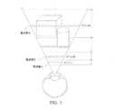
アドレス指定可能な焦点手がかりを用いた立体視ディスプレイは、3次元仮想物体の正確なまたはほぼ正確な焦点手がかりを描画する機能を提供するうえでの根本的な調節/輻輳問題を解決するための、将来的に最も有望な方法の1つである。従来の立体視ディスプレイとは異なり、アドレス指定可能な焦点手がかりを用いた立体視ディスプレイは、視聴者の関心のある領域に基づいて能動光学素子によって仮想表示の焦点距離を動的に変化させる、可変焦点表示モードとして知られる機能、または視聴者の関心のある領域を追跡する必要なくフリッカーフリーの速度で複数の焦点面を表示する、多焦点表示モードとして知られる機能のいずれかを可能とする。例えば、多焦点面ディスプレイは、視軸上に綿密に配置された複数の個別の焦点距離の位置に遠近感のある2次元画像を表示する。これらの個別の焦点面は、3次元光景の体積を複数のゾーンとしてサンプリングし、各ゾーン内の物体は、図1に示すように、このゾーンに対応する隣り合った1対の焦点面によって描画される。したがって、多焦点面ディスプレイは、異なる奥行きにある仮想物体のための正確なまたはほぼ正確な焦点手がかりを描画することができる。ホログラフィックディスプレイおよびボリュメトリックディスプレイのような多視点ディスプレイとは対照的に、多焦点面ディスプレイは固視点ディスプレイである。視点位置を制限することにより、多焦点面ディスプレイシステムは、少数の視点を表示するだけでよい。また、多焦点ディスプレイは、2次元表示における視差、閉塞、および遠近法、ならびに正反射および陰影などの視角依存性の照明効果の描画を維持することができる。実運用上は、多焦点面ディスプレイの実施は、空間多重化または時間多重化の2つに分類することができる。空間多重化システムでは、複数の2次元表示を積み重ねることにより多焦点機能が実現される。より洗練された別の方法である時間多重化システムでは、単一の2次元表示からの画像の焦点距離が、複数の焦点面のフレーム描画と同期した能動光学素子によって高速で切り替えられる。一般に、多焦点面ディスプレイは、光学系の配置をあまり変更せずに可変焦点モードで使用できるようにすることが容易である。 Stereoscopic displays with addressable focus cues solve the fundamental adjustment / congestion problem in providing the ability to draw accurate or near-accurate focus cues for 3D virtual objects. It is one of the most promising methods in the future. Unlike conventional stereoscopic displays, stereoscopic displays with addressable focal cues are variable, with active optical elements dynamically changing the focal length of the virtual display based on the area of interest to the viewer. It enables either a feature known as focus display mode or a feature known as multifocal display mode that displays multiple focal planes at flicker-free speed without the need to track the area of interest to the viewer. For example, a multifocal surface display displays a perspective two-dimensional image at a plurality of individual focal length positions closely arranged on the visual axis. These individual focal planes sample the volume of the 3D scene as multiple zones, and the objects in each zone are drawn by a pair of adjacent focal planes corresponding to this zone, as shown in FIG. Will be done. Therefore, a multifocal surface display can draw accurate or near-accurate focus cues for virtual objects at different depths. In contrast to multi-view displays such as holographic and volumetric displays, multifocal surface displays are solid-view displays. By limiting the viewpoint position, the multifocal surface display system only needs to display a small number of viewpoints. Multifocal displays can also maintain parallax, obstruction, and perspective in a two-dimensional display, as well as viewing angle-dependent lighting effects such as specular and shading. In practice, the implementation of multifocal surface displays can be divided into two categories: spatial multiplexing or time multiplexing. In a spatial multiplexing system, a multifocal function is realized by stacking a plurality of two-dimensional displays. In another more sophisticated method, the time multiplexing system, the focal length of an image from a single 2D display is quickly switched by active optics synchronized with the frame drawing of multiple focal planes. In general, multifocal surface displays can be easily made available in variable focus mode without much change in the arrangement of the optics.
さらに、最近では、この参照によりその内容が本明細書内に組み込まれる共同所有の米国特許出願公報第2011/0075257号に反映されているように、奥行き知覚が改善されたアドレス指定可能な焦点面を有しながらも必要な計算能力を既存の方法よりもかなり軽減した、ヘッドマウント式とすることのできる立体視ディスプレイの分野で進捗が見られる。しかし、アドレス指定可能な焦点手がかりを用いた立体視ディスプレイにおいて向上した撮像性能を提供できる光学撮像システムの必要性が、依然として存在する。 Moreover, more recently, addressable focal planes with improved depth perception, as this reference reflects in co-owned US Patent Application Publication No. 2011/0075257 incorporated herein by reference. Progress is being made in the field of stereoscopic displays, which can be head-mounted, but have significantly reduced the required computing power compared to existing methods. However, there is still a need for an optical imaging system that can provide improved imaging performance in stereoscopic displays with addressable focal cues.
本発明は、その一観点において、ユーザーに向けて表示するための仮想画像を提供するマイクロディスプレイを有する、アドレス指定可能な焦点手がかり(addressable focus cues)を用いた仮想ディスプレイシステムを提供することができる。また、可変屈折力を提供するように構成された能動反射光学素子を提供することもできる。リレーレンズの共役平面に前記マイクロディスプレイと能動光学素子とを配置するようにして、前記マイクロディスプレイと前記能動光学素子との間の光路上に前記レリーレンズを配置することができる。前記マイクロディスプレイと前記能動光学素子との間の光路上に、前記能動光学素子から光放射を受光する方向に、ビームスプリッターを配置することができる。さらに、前記ビームスプリッターから光放射を受光し、受光した前記放射を前記システムの射出瞳に向けて反射させて仮想表示光路を提供するように構成された選択面を含む、シースルー接眼レンズを設けることもできる。前記選択面はまた、前記マイクロディスプレイ以外の(現実世界などの)光源から光放射を受光し、当該光放射を前記射出瞳に透過させてシースルー光路を提供するように構成することもできる。前記接眼レンズはフリーフォームのプリズム形状を含むことができ、具体的には、前記ビームスプリッターから光放射を受光し、これを屈折させるように構成された第1の面を含むことができ、かつまた前記第1の面から屈折した前記光放射を受光するように構成され、前記光放射を前記接眼レンズの前記選択面に向けて反射させるように構成された第2の面を含むことができる。前記第2の面は、前記光放射を内部全反射させるように構成することができ、また前記接眼レンズの前記面のうちの1つ以上は、回転非対称な面を有することができる。 From one aspect of the present invention, it is possible to provide a virtual display system using addressable focus queues, which has a microdisplay that provides a virtual image for display to a user. .. It is also possible to provide an active catoptric element configured to provide variable refractive power. The release lens can be arranged on the optical path between the microdisplay and the active optical element so that the microdisplay and the active optical element are arranged on the conjugate plane of the relay lens. A beam splitter can be arranged on the optical path between the microdisplay and the active optical element in a direction in which light radiation is received from the active optical element. Further, a see-through eyepiece is provided that includes a selection surface configured to receive light radiation from the beam splitter and reflect the received radiation toward the exit pupil of the system to provide a virtual display optical path. You can also do it. The selection surface can also be configured to receive light radiation from a light source other than the microdisplay (such as in the real world) and transmit the light radiation through the exit pupil to provide a see-through optical path. The eyepiece can include a free-form prismatic shape, specifically a first surface configured to receive light radiation from the beam splitter and refract it. Further, it can include a second surface configured to receive the light radiation refracted from the first surface and to reflect the light radiation toward the selection surface of the eyepiece. .. The second surface can be configured to totally reflect the light radiation internally, and one or more of the surfaces of the eyepiece can have a rotation asymmetric surface.
本発明は、その別の観点において、ユーザーに向けて表示するための仮想画像を提供するマイクロディスプレイを有するアドレス指定可能な焦点手がかりを用いた仮想ディスプレイシステム、および光放射を前記マイクロディスプレイから前記システムの射出瞳へと反射させるように構成された反射光学素子を有する接眼レンズを提供することができる。可変屈折力を提供するように構成された能動屈折光学素子を有するリレーレンズを、前記マイクロディスプレイと前記接眼レンズとの間の光路に沿って配置して前記マイクロディスプレイから前記接眼レンズに画像を中継することができる。前記リレーレンズは前記第1および第2のレンズ群を含み、当該第1のレンズ群と第2のレンズ群はその間に位置する前記能動光学素子と共に前記光路に沿って配置される。さらに、ビームスプリッターを、前記マイクロディスプレイと前記接眼レンズとの間の前記光路に沿って配置し、前記マイクロディスプレイ以外(現実世界など)の光源からの光放射を受光し、これを前記射出瞳に透過させてシースルー光路を提供するように構成することができる。前記接眼レンズは球面鏡を有することができ、前記システムは前記マイクロディスプレイ内でテレセントリックであることができる。前記システムはまた、3よりも小さいF値を有することができる。 In another aspect of the present invention, a virtual display system using addressable focus cues having a microdisplay that provides a virtual image for display to the user, and light emission from the microdisplay to the system. It is possible to provide an eyepiece having a reflective optical element configured to reflect the light into the exit pupil of the eyepiece. A relay lens having an active refracting optical element configured to provide variable refractive power is arranged along the optical path between the microdisplay and the eyepiece to relay an image from the microdisplay to the eyepiece. can do. The relay lens includes the first and second lens groups, and the first lens group and the second lens group are arranged along the optical path together with the active optical element located between them. Further, a beam splitter is arranged along the optical path between the microdisplay and the eyepiece to receive light radiation from a light source other than the microdisplay (such as in the real world), and this is applied to the exit pupil. It can be configured to be transparent to provide a see-through optical path. The eyepiece can have a spherical mirror and the system can be telecentric within the microdisplay. The system can also have an F value less than 3.
本発明の前述の概要および以下の例示的な実施形態の詳細な説明は、添付の図面と併せて読むと、より深く理解することができる。
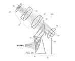
ここで、本発明の一観点による、すべての図を通して同様の要素には同様の番号を付した図を参照すると、図2は、アドレス指定可能な焦点手がかりを用いた奥行き融合型多焦点面立体視ディスプレイ(in depth−fused multi−focal−plane stereoscopic displays)において高画質を提供するために特に好適な例示的な光学系の一次非屈曲光路を概略的に図示している。図3Aおよび3Bは、図2の配置に従った具体的な設計を概略的に図示しており、図3Aでは第1の光学系100が単一の視野レンズ18を有し、図3Bでは別の方法の系200が2つの素子17および19から成る視野レンズ18を有している。(視聴者の一方の眼に供する1組の光学系を図示しているものの、最終的な立体視装置では、このような光学系を各々の眼に1組のずつ、2組提供されることが分かる。) Here, referring to a diagram in which similar elements are similarly numbered throughout all the figures according to one aspect of the present invention, FIG. 2 shows a depth fusion type multifocal plane stereoscopic using addressable focal cues. The primary non-bending optical path of an exemplary optical system, which is particularly suitable for providing high image quality in a visual display (in invention-used multi-focal-plane stereoscopic displays), is schematically illustrated. 3A and 3B schematically illustrate a specific design according to the arrangement of FIG. 2, where the first
前記設計の関連性のある特徴は、デジタル・マイクロ・ミラー装置(digital micro−mirror device:DMD)60などのから接眼レンズ12の前部に前記画像を中継するリレーレンズ群20が含まれていることである。前記レリーレンズ群20は、従来の非変形レンズ21、および図2の膜可変形鏡80のような能動反射光学素子を含むことができる。前記リレーレンズ21は、図3Aおよび図3Bの1対のダブレット22、24とレンズ26とを含むことができる。前記膜可変形鏡装置(deformable membrane mirror device:DMMD)80は、前記リレーレンズ21の焦点面に配置することができ、前記系の絞りとして機能することができる。図2の前記レンズ21(または図3Aおよび3Bのレンズ22、24、および26)並びに前記DMMD80は、協働して奥行き融合型多焦点面立体視ディスプレイに特に好適な屈曲両側テレセントリック系を提供することができる。両側テレセントリックリレー20を設計する利点は、前記DMMD80上の屈折力が変化しても前記画像の拡大倍率は変化せずに中間画像の位置のみが変化するので、前記系の視野および視点空間の角度分解能が一定に保たれ、複数の焦点面上の対応する画素が1対1で相互に重なり合うことである。このように、図3Aおよび3Bの設計は、さもなくば像の異なる拡大倍率に起因して位置ずれを起こす複数の焦点画像の補正を必要としない奥行き融合技術に非常に好適である。これらの便益は、焦点手がかりおよび調節範囲の解析によってさらによく理解することができる。 A relevant feature of the design includes a
前記系が描画することのできる前記3次元体積の奥行き範囲を意味する焦点手がかりまたは調節範囲ΔDaccomodationは、下記式によって決定される。The focal clue or adjustment range ΔDaccomodation , which means the depth range of the three-dimensional volume that the system can draw, is determined by the following equation.

但し、Φeyeは前記接眼レンズ12の倍率、Φ1は前記リレーレンズ21の倍率であり、およびΔDMMDは前記可変形鏡80が変化できる倍率の範囲を示す。上記の等式によって、前記リレーレンズ20の焦点距離と前記接眼レンズ12との間の関係が求められる。前記接眼レンズ12は前記系の絞り、即ち前記DMMD80を中継して射出瞳を形成するので、所望の前記調節範囲が決定されると、前記射出瞳Dxpのサイズと前記DMMD80のサイズとの間の比は固定される。However, Φeye indicates the magnification of the
前記屈曲両側テレセントリックリレーの設計の1つの欠点は、前記DMDディスプレイ60の画像に拡大倍率を提供しないことである。したがって、所望の系の視野を得るためには、前記DMDディスプレイ60の前部に視野レンズ18を追加して前記画像を拡大すればよい。(前記ディスプレイ60は発光型ディスプレイでもよく、または照明光路を通じて照明される反射型ディスプレイであってもよい。)前記視野レンズ18がもたらす前記拡大倍率は、下記式のとおりである。 One drawback of the bent bilateral telecentric relay design is that it does not provide magnification for the image on the
このとき、前記系の半視野は下記式となる。At this time, the half field of view of the system is as follows.
その設計目標、装置の仕様、および力学的考察に基づいて、図3Aおよび3Bの設計の一次系の仕様を表1に掲載する。 Based on its design objectives, device specifications, and mechanical considerations, Table 1 lists the primary system specifications for the designs in FIGS. 3A and 3B.
フリーフォーム接眼レンズおよび補償板
前記系100および200の光学シースルー機能は、ビームスプリッターを使用して、仮想表示光学系(例えば、DMD60、視野レンズ18、およびリレーレンズ群20)が妨げとならないようにこれらを屈曲させることにより実現することができる。しかし、この設計における前記接眼レンズ12が短い焦点距離を有することから、従来の方法で前記系を設計することは非常に困難であった。Freeform eyepieces and compensators The optical see-through features of the
この即製の例示的な設計において、より洗練された解決策を模索した。図3Cおよび3Dに示すように、前記接眼レンズ12をくさび形をしたフリーフォームのプラスチックレンズとして設計した。前記フリーフォームのプリズム接眼レンズ12は、それぞれS1、S2、およびS3と名付けられた3つの回転非対称な面を含むことができる。図3Dの前記仮想表示光路について検討すると、前記ディスプレイ60の中間画像からの光線は、まず前記面S3によって屈折する。面S1およびS2によって2度連続して屈折した後、前記光線は前記面S1を透過し、前記系の射出瞳(眼の瞳孔)に達する。前記面S1は、前記面S1上で反射する全光線について内部全反射の条件を満たすことが望ましい。前記接眼レンズ12の面S2は、前記光学シースルー機能を助長するためにハーフミラーとして被覆することができる。2つの回転非対称な面S2およびS4を含むことのできるフリーフォーム補償板14を前記接眼レンズ12に接着することができ、前記2つの部品12および14が図3Cのように結合されると、現実世界の光景からの光線にもたらされる収差およびゆがみが補償される。さらに、任意選択的に採用できる円柱レンズ13を前記フリーフォーム補償板14と一緒に含めて前記シースルー光路の収差およびゆがみを最小限に抑えるために役立てることができる。 In this ready-made exemplary design, we sought a more sophisticated solution. As shown in FIGS. 3C and 3D, the
所望の前記光学性能を達成するために、MTF値を選択して画像の全体的な鮮鋭度を評価した。前記仮想表示系100は前記接眼レンズ12から前記ディスプレイ60へと逆行して設計されたので、その目的は、前記ディスプレイ60上で、14μmの画素サイズのカットオフ周波数である36lp/mmの空間周波数で20%以上のMTF値を有することであった。人間の眼は1分角の角度分解能を有する。したがって、前記補償板14は、現実世界の光景の劣化を最小限に抑えるために30サイクル/度での前記MTF値が0.2よりも大きくなるように最適化された。前記系100および200のもう1つの重要な光学性能の要素は、画像のゆがみであった。従来の系において、ゆがみは規則的であり、電子的または演算的に容易に補正することができる。しかし、フリーフォームの軸外し光学系を有する系では、前記ゆがみは非常に大きく不規則な場合がある。したがって、前記系100および200の設計は、前記視野全体に亘ってサンプリングされたゆがみに対して厳しい制約を有するべきである。前記ゆがみは、前記シースルー視野を通して見る物体の大きさおよび形状を変える可能性があり、したがって3次元知覚に大きな影響を与えるので、前記シースルー光路にとって特に重要である。 To achieve the desired optical performance, MTF values were selected to evaluate the overall sharpness of the image. Since the
設計および最適化の手順
前記系100および200の設計には、前記仮想表示光路と前記シースルー光路との2段階が必要であった。前記仮想表示光路について、CodeV内に前記リレーレンズ20および視野レンズ18と共に前記フリーフォーム接眼レンズ12を設定し、一緒に最適化した。前記40度のFOVおよび前記所望の3ディオプターの調節範囲全域に亘ってサンプリングされた視野について、前記表示性能を均衡させた。前記仮想表示の最適化が完了した後、前記フリーフォーム接眼レンズ12を前記補償板14と共に設定し、前記補償板の背面S4をシースルー性能について最適化した。視野の中央部40度を強調しながら、60度について前記シースルー性能を最適化した。前記系の性能が向上するに従って前記フリーフォーム面の可変表面係数の数値を徐々に増加することによって、両方の段階に漸進的最適化手順を採用した。Design and Optimization Procedure The design of the
最終的な設計において、前記フリーフォーム接眼レンズ並びに補償板の面S1、S2、S3、およびS4を第10次までのXY多項式によって表し、PMMA上での単一点ダイヤモンド回転によりプロトタイプを製作した。図3Bの系200において、前記視野レンズ素子のうちの1つである素子17を最適化し、回折光学特徴を付加して前記フリーフォーム接眼レンズ12によってもたらされる色収差を補正した。プロトタイプ製作コストを削減するため、その他のレンズ19、22、24、および26は、すべて既製品の構成要素である。 In the final design, the surfaces S1, S2, S3, and S4 of the freeform eyepiece and compensator were represented by XY polynomials up to the 10th order, and a prototype was made by single point diamond rotation on PMMA. In the
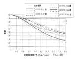
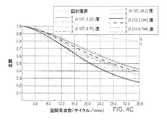
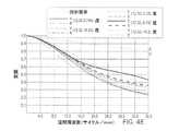
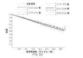
3mmの瞳孔について評価した前記仮想表示の多色MTF値は、図4A〜4Eに示すように、40度の視野全域に亘って36lp/mmで0.2よりも大きく、中心視野値は0.5である。また、前記仮想表示の示すゆがみは、図4Fに示すように最小限である。3mmの瞳孔について評価した前記シースルー光路の多色MTF値は、図5A〜5Eに示すように、40度の視野全域に亘って30サイクル/度で0.4よりも大きい。また、前記シースルー光景のゆがみも、図5Fに示すように非常に良好に補正された。図3Bの具体的な設計のための処方度数を以下のとおりに提供する。 As shown in FIGS. 4A to 4E, the multicolor MTF value of the virtual display evaluated for the pupil of 3 mm was larger than 0.2 at 36 lp / mm over the entire field of view of 40 degrees, and the central field of view value was 0. It is 5. Further, the distortion indicated by the virtual display is minimal as shown in FIG. 4F. The multicolor MTF value of the see-through optical path evaluated for a 3 mm pupil is greater than 0.4 at 30 cycles / degree over the entire 40 degree field of view, as shown in FIGS. 5A-5E. In addition, the distortion of the see-through scene was also corrected very well as shown in FIG. 5F. The prescription frequencies for the specific design of FIG. 3B are provided as follows.
仮想表示光路のための系の処方度数
表2では、面2番〜4番は前記フリーフォーム接眼レンズ12の仕様を定めている。面2番および4番は、物理的に同一の面を示しており、また接眼レンズの面S1として表示されている。面3番もまた接眼レンズの面S2として表示されており、面5番もまた接眼レンズの面S3として表示されている。面8番〜15番および面17番〜24番は、複光路内に形成されたリレーレンズ22、24、および26と同様の群である。前記可変形鏡80は、面16番に形成される。面25番および26番は、45度の前記ビームスプリッター16を形成する。面27番〜28番は前記視野レンズ素子17を示しており、面29番〜30番は前記視野レンズ素子19を示している。In the prescription power table 2of the system for the virtual display optical path, the specifications of the free-
シースルー光路のための系の処方度数
表3では、面2番および3番は、前記仮想表示光路と同様に形成された接眼レンズ面S1およびS3である。面4番および5番は、前記フリーフォーム補償板14の仕様を定めている。面4番は、面3番(接眼レンズ面S3)の正確な複製である。In the prescription power table 3of the system for the see-through optical path , the
前記系の処方度数の表(例えば、表2および表3)中で使用されるとき、「XY多項式面」という言葉は、下記の等式で表すことのできる面を指す。 When used in the prescription frequency tables of the system (eg, Tables 2 and 3), the term "XY polynomial plane" refers to a plane that can be represented by the following equation.
但し、zは局部的なxyz座標系のz軸に沿って測定されたフリーフォーム面のたるみ、cは頂点曲率(CUY)、rは半径距離、kは円錐定数、Cjはxmynの係数である。表中の「非球面」という言葉は、下記の等式で表すことのできる非球面を指す。However, z is local xyz coordinate system z freeform surface measured along the axis sag, c is the vertex curvature (CUY), r is the radial distance, k is the conic constant,C j isx my n It is a coefficient of. The word "aspherical surface" in the table refers to an aspherical surface that can be expressed by the following equation.
但し、zは局部的なxyz座標系のz軸に沿って測定された面のたるみ、cは頂点曲率、rは半径距離、kは円錐定数、A〜Eはそれぞれ4次、6次、8次、10次、および12次の変形係数である。However, z is the slack of the surface measured along the z axis of the local xyz coordinate system, c is the vertex curvature, r is the radial distance, k is the conical constant, and A to E are the 4th, 6th, and 8th, respectively. The next, tenth, and twelfth deformation coefficients.
前記第2の視野レンズ素子17の処方度数に目を向けると、前記視野レンズ素子17の両面が非球面である。さらに、前記視野レンズ素子17の面29番(表2)は、以下の等式によって表すことができるキノフォーム回折光学特徴を有する。 Looking at the prescription power of the second visual
但し、Φは回折素子の位相関数、rは半径距離、A〜Eはそれぞれ4次、6次、8次、10次、および12次の位相定数である。前記第2の視野レンズ素子17の面の処方度数を、表10〜12に提供する。However, Φ is the phase function of the diffraction element, r is the radial distance, and A to E are the fourth, sixth, eighth, tenth, and twelfth phase constants, respectively. The prescription powers of the surfaces of the second visual
円柱レンズを用いない別の方法による例示的な設計
上記の図3Aおよび3Bの設計では、収差およびゆがみを最小限に抑えるうえで役立つように、前記フリーフォーム補償板14と共に任意選択的に採用可能な円柱レンズ13を含めている。前記円柱レンズ13を用いない別の方法の設計もまた提供しており、この設計では、前記仮想表示光路は、図3Bおよび表2に示すのと同様である。前記円柱レンズ13の存在しない前記シースルー光路のその他残りの面についての唯一の違いは、前記接眼レンズ/補償板の面S2(表3のシースルー光路の面5番)である。表15では、面2番および3番は、前記仮想表示光路の場合と同様に形成された接眼レンズ面S1およびS3である。面4番および5番は、前記フリーフォーム補償板14について説明している。面4番は、面3番の正確な複製である。Illustrative Design by Another Method Without a Cylindrical Lens The designs in FIGS. 3A and 3B above can be optionally adopted with the
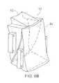
図3Bの系のプロトタイプ
既製品のレンズおよびカスタム化した光学系を用いて図3Bの多焦点面ディスプレイシステム200のプロトタイプを製作した。その3次元表示を図6Aおよび6Bに提供する。視聴者の頭部に当たらないように前記システム200を屈曲させた。また、前記DMD60(ノルウェー、Drammen市のVISITECH社製LUXBEAM(登録商標)4500)上の表示画像、前記LED(図示せず)の照明、および前記可変形鏡80(オランダ、Rijswijk町のFlexible Optical B.V.社製OKO(登録商標)Technologies MMDM10−1−focus)の焦点面の切替えを制御し同期させるために、カスタム電子回路も開発した。Prototype of the system of FIG. 3B A prototype of the multifocal
傾斜平面の物体および緑色のフロアグリッド(双方とも0ディオプターから2.5ディオプターまで延在)から構成された連続3次元光景を描画した。前記光景を、前記対象物の奥行き値に基づいて3ディオプター、2.4ディオプター、1.8ディオプター、1.2ディオプター、0.6ディオプター、および0ディオプターに配置した6面の焦点面に分解し、奥行き融合技術を使用して6面の前記焦点面を滑らかな連続体として融合させた。前記3次元光景全体を約60Hzでリフレッシュしたので、フリッカーは視認できなかった。図7Aは、前記システムを通して見た6面の前記焦点面の実際の光景を示しているが、前記画像は鮮鋭で、ゆがみは非常に小さかった。特別なアルゴリズムを使用せずとも、前記一定視野設計により、異なる焦点面上の画素が重なり合い、滑らかに融合する。さらに、被写界深度の浅いカメラレンズを使用し、前記光景の異なる部分で手動で焦点を合わせた。図7Bでは、バックウォールに分解能ターゲットを表示し、前記カメラの焦点を約2mに合わせた。前記フロアグリッドの終端付近では焦点が合っておらず、背景グリッド並びにロゴには鮮鋭に焦点が合っていた。図7Cでは、前部焦点面に分解能ターゲットを表示し、前記カメラの焦点を30cmに合わせた。今度は、近くの光景の焦点が合い、後方のコンテンツがぼやけていた。このように、前記プロトタイプに、高画質高分解能のカラー画像の6面以上の焦点面をフリッカーフリーの速度で描画する能力があることを実証した。前記プロトタイプはまた、拡張現実感アプリケーションのための非常に良好なシースルー光学特性を有していたし、奥行き知覚正確度の向上、立体視力の向上、および利用者の疲労の低減を提供する可能性を有する。 A continuous three-dimensional scene composed of a slanted plane object and a green floor grid (both extending from 0 diopters to 2.5 diopters) was drawn. The scene is decomposed into 6 focal planes arranged in 3 diopters, 2.4 diopters, 1.8 diopters, 1.2 diopters, 0.6 diopters, and 0 diopters based on the depth value of the object. , The six focal planes were fused as a smooth continuum using a depth fusion technique. Since the entire three-dimensional scene was refreshed at about 60 Hz, the flicker was not visible. FIG. 7A shows the actual view of the six focal planes as seen through the system, but the image was sharp and the distortion was very small. The constant field of view design allows pixels on different focal planes to overlap and blend smoothly without the use of a special algorithm. In addition, a camera lens with a shallow depth of field was used to manually focus on different parts of the scene. In FIG. 7B, the resolution target was displayed on the back wall and the camera was focused to about 2 m. Near the end of the floor grid, it was out of focus, and the background grid and logo were sharply focused. In FIG. 7C, a resolution target is displayed on the front focal plane and the camera is focused at 30 cm. This time, the nearby scene was in focus and the content behind was blurry. In this way, it was demonstrated that the prototype has the ability to draw six or more focal planes of a high-quality, high-resolution color image at a flicker-free speed. The prototype also had very good see-through optical properties for augmented reality applications, potentially providing improved depth perception accuracy, improved stereoscopic vision, and reduced user fatigue. Have.
別の方法による例示的な焦点可変レンズ
本発明は、その別の観点において、反射型液晶素子(Liquid Crystal on Silicon:LCOS)および強磁性反射型液晶(Ferroelectric Liquid Crystal on Silicon:FLCoS)などの高速表示技術と、電気式焦点可変レンズ380などの高速の能動屈折光学素子とを組み合わせて例示的な多焦点面ディスプレイシステム300を提供する。その具体的な設計は、0.8インチWXGA LCOS/FLCOSディスプレイ360および10mm口径の電気式焦点可変レンズ380(スイス、Dietikon市のOptotune AG社製Optotune EL−10−30)に基づいている。前記焦点可変レンズ380は、前記レンズ380を通って電流が流れると形状を変化させて屈折力に変化を生じさせる。前記Oputotuneレンズ380は約2.5msの応答時間を有するので、多焦点面ディスプレイに使用できる可能性がある。Illustrative Focus Variable Lens by Another Method In another aspect, the present invention is fast, such as a Liquid Crystal on Silicon (LCOS) and a Ferroelectric Liquid Crystal on Silicon (FLCoS). An exemplary multifocal
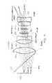
前記設計の最終的な配置を図10A〜11に示す。リレーレンズ群(レンズ302、304、306、380、308、および310)が前記画像を球面鏡318に中継し、この球面鏡318が接眼レンズとして機能し、ユーザーのために仮想画像を形成する。前記鏡318は、選択的に非球面であってもよい。シースルー機能を可能とするために、ビームスプリッター316が使用されている。前記焦点可変レンズ380は前記システムの絞りを提供することができ、前記システムは、LCOS/FLCoSの要件のために前記マイクロディスプレイ360に対してテレセントリックであることができる。また、図11の照明ビームスプリッター317のために十分な空間も与えられている。前記システム300の処方度数を、表19〜26に提供する。(表19では、面9番〜12番が前記Optotune電気式焦点可変レンズ380を形成する。)前記システムの性能を、図12Aおよび12Bに図示する。 The final arrangement of the design is shown in FIGS. 10A-11. The relay lens group (
全体的な設計上の検討
本発明は、その別の観点において、奥行き融合型ディスプレイ(depth−fused display:DFD)システムの設計パラメータを決定するための新しい判定基準に関する。DFDディスプレイ内の融合画素の光学品質はその網膜像の点像分布関数(point spread function:PSF)によって定量化され、または等価的に、前記3次元表示上の正弦波物体のコントラスト変調に対する前記網膜像のコントラスト変調の比により特徴付けられる変調伝達関数(modulation transfer function:MTF)によって定量化される。例えば、描画されている奥行きzに眼が調節されると、z1およびz2にそれぞれ位置する隣接した1対の焦点面上の2つの画素による融合画素のPSFであるPSF12は、下記式のとおり、前方の画素および後方の画素からのPSFの加重和として説明することができる。Overall Design Review In another aspect, the present invention relates to new criteria for determining design parameters for a depth-fused display (DFD) system. The optical quality of the fusion pixels in the DFD display is quantified by the point spread function (PSF) of the retinal image, or equivalently, the retina with respect to the contrast modulation of the sinusoidal object on the three-dimensional display. It is quantified by a modulation transfer function (MTF) characterized by the ratio of contrast modulation of the image. For example, when the eye is adjusted to the drawn depth z, the PSF12 which is a fusion pixel PSF by two pixels on a pair of adjacent focal planes located at z1 and z2 , respectively, is expressed by the following equation. As described above, it can be described as a weighted sum of PSFs from the front pixel and the rear pixel.
但し、PSF1(z,z1)およびPSF2(z,z2)は、眼が距離zに調節されているときの前方および後方の画素の点像分布関数である。式(1)中のPSFは、前記加重和を計算する前に前方および後方の画素が同じ輝度を有するように、正規化される。w1およびw2は、前記前方および後方の画素の輝度を変調して奥行きに重み付けした融合関数であり、シミュレートされた奥行きが変化したときに前記融合画像の総輝度が変化しないように、通常、w1(z)+w2(z)=1が強制されている。次に、PSF12(z)のフーリエ変換によって前記ディスプレイのMTFを計算することができる。However, PSF1 (z, z1 ) and PSF2 (z, z2 ) are point image distribution functions of the front and rear pixels when the eye is adjusted to the distance z. The PSF in equation (1) is normalized so that the front and rear pixels have the same brightness before calculating the weighted sum. w1 and w2 are fusion functions in which the brightness of the front and rear pixels is modulated and weighted to the depth so that the total brightness of the fusion image does not change when the simulated depth changes. Normally, w1 (z) + w2 (z) = 1 is forced. The MTF of the display can then be calculated by the Fourier transform of PSF12 (z).
二重焦点面DFDディスプレイのシミュレートされた網膜像のMTFプロットの例を、図8Aに示す。前記シミュレーションにおいて、前記2面の焦点面をそれぞれ1.2ディオプターおよび1.8ディオプターの位置に配置し、前記2面の焦点面間の輝度比は1:1であり、前記融合画素が前記前方および後方の焦点面の中間視度、即ち、1.5ディオプターでシミュレートされたことを示した。前記奥行き融合の効果に集中するために、瞳孔が3mmの眼球モデルを選択し、すべての残存収差を除去した。図8Aは、眼が前記2面の焦点面間の様々な位置に調節するに従って、前記網膜像のMTFがどのように変化するかを示している。図8Bは、異なる空間周波数についての眼の調節距離の関数としてのコントラスト勾配を示しているが、各周波数についてのピークコントラストを黒い四角のマーカーでマーキングした。双方のプロットから、約17サイクル/度(cycle/degree:cpd)の遷移周波数が観察される。その遷移周波数未満では、前記網膜像のMTFは、前記二重焦点面システム内での1:1の輝度比によってシミュレートされた奥行きである1.5ディオプターの中間視度で最大化される。さらには、眼が遠方側または手前側のいずれかの焦点面から前記シミュレートされた奥行きに近づくに従い、前記MTFの値が滑らかに上昇し、眼に前記調節をさせるために必要な適切なコントラスト勾配を提供する。しかし、17cpdよりも高い周波数については、前記融合画素のコントラストは常に、眼が物理的な焦点面またはその付近に調節されているときに最高となり、即ち、前記コントラスト勾配は前記調節を前記シミュレートされた画素奥行きから遠ざける傾向を有するので、相反する調節手がかりを生じさせてしまう。 An example of an MTF plot of a simulated retinal image of a bifocal surface DFD display is shown in FIG. 8A. In the simulation, the focal planes of the two planes are arranged at the positions of 1.2 diopters and 1.8 diopters, respectively, the brightness ratio between the focal planes of the two planes is 1: 1, and the fusion pixel is in front of the front. It was shown that it was simulated with an intermediate diopter of the rear focal plane, that is, 1.5 diopters. To focus on the effect of depth fusion, an eye model with a pupil of 3 mm was selected to remove all residual aberrations. FIG. 8A shows how the MTF of the retinal image changes as the eye adjusts to various positions between the two focal planes. FIG. 8B shows the contrast gradient as a function of the accommodation distance of the eye for different spatial frequencies, with the peak contrast for each frequency marked with a black square marker. From both plots, a transition frequency of about 17 cycles / degree (cycle / degree: cpd) is observed. Below that transition frequency, the MTF of the retinal image is maximized with an intermediate diopter of 1.5 diopters, which is the depth simulated by the 1: 1 luminance ratio within the bifocal plane system. Furthermore, as the eye approaches the simulated depth from either the far or front focal plane, the MTF value rises smoothly and the appropriate contrast required for the eye to make the adjustment. Provide a gradient. However, for frequencies above 17 cpd, the contrast of the fusion pixels is always highest when the eye is adjusted to or near the physical focal plane, i.e. the contrast gradient simulates the adjustment. Since it tends to move away from the pixel depth, it causes conflicting adjustment clues.
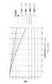
図9Aおよび9Bは、前記遷移周波数が、焦点面間の間隔の関数および瞳孔のサイズの関数としてどのように変化するかを示している。図9Aは3mmの眼の瞳孔を想定しており、図9Bは0.6ディオプターの一定した焦点面間の間隔を想定している。この結果は、前記焦点面間の間隔が狭いほど、および前記設計された眼の瞳孔のサイズが小さいほど、前記遷移点の周波数が高くなることを示唆している。したがって、DFDディスプレイを設計するうえでの非常に重要な判定基準は、前記焦点面間の間隔および前記ディスプレイの実用的な瞳孔のサイズを、相反する調節手がかりの視聴者への提示を回避するために、前記コントラスト勾配の反転点が前記システムのカットオフ周波数よりも高くなるように決定すべきことである。例えば、1.8分角/画素(約17cpdの空間周波数)の角度分解能および10cd/m2よりも高い輝度を提供するDFDディスプレイでは、隣接する焦点面間の間隔を0.6ディオプターとすれば十分であるとみなすことができる。10cd/m2の表示輝度の刺激によって、眼の瞳孔の直径は約3mmとなる。1分角/画素(即ち30cpd)の角度分解能を提供するディスプレイでは、0.45ディオプター以下の間隔が望まれるであろう。画素当たりの前記角度分解能が小さいほど、または前記画像の明るさが低いほど、必要とされる焦点面間の間隔が小さくなるであろう。9A and 9B show how the transition frequency changes as a function of the spacing between focal planes and as a function of pupil size. FIG. 9A assumes a pupil of the eye of 3 mm and FIG. 9B assumes a constant distance between focal planes of 0.6 diopters. This result suggests that the narrower the distance between the focal planes and the smaller the size of the designed pupil of the eye, the higher the frequency of the transition point. Therefore, a very important criterion in designing a DFD display is to avoid presenting conflicting adjustment cues to the viewer for the spacing between the focal planes and the practical pupil size of the display. In addition, the inversion point of the contrast gradient should be determined to be higher than the cutoff frequency of the system. For example, in a DFD display that provides an angular resolution of 1.8 arcmin / pixel (spatial frequency of about 17 cpd) and a brightness higher than 10 cd / m2 , if the spacing between adjacent focal planes is 0.6 diopters. Can be considered sufficient. The diameter of the pupil of the eye becomes about 3 mm by the stimulation of the display brightness of 10 cd / m2 . For displays that provide angular resolution of 1 arcmin / pixel (
前述の明細書から、当業者には、これらおよびその他の本発明の利点が明らかとなるであろう。したがって、当業者であれば、本発明の広範な発明概念から逸脱することなく、上述の実施形態に変更または修正を加えることができることを認識するであろう。したがって、本発明は、本明細書内で説明した特定の実施形態に限定されるものではなく、請求項に明記した本発明の範囲および趣旨を逸脱しないすべての変更および修正を含むことが意図されることを理解すべきである。 From the specification described above, those skilled in the art will appreciate these and other advantages of the present invention. Therefore, one of ordinary skill in the art will recognize that modifications or modifications can be made to the above embodiments without departing from the broad invention concept of the present invention. Accordingly, the invention is not limited to the particular embodiments described herein, and is intended to include all modifications and modifications that do not deviate from the scope and intent of the invention as set forth in the claims. You should understand that.
Claims (8)
Translated fromJapaneseユーザーに表示するための仮想画像を提供するマイクロディスプレイと、
可変屈折力を提供するように構成された能動反射光学素子と、
前記マイクロディスプレイと前記能動反射光学素子との間の光路上において、前記能動反射光学素子から光放射を受光する方向に配置されたビームスプリッターと、
前記ビームスプリッターから光放射を受光し、受光した光放射を前記仮想ディスプレイシステムの射出瞳に反射させて仮想表示光路を提供するとともに、前記マイクロディスプレイ以外の光源から光放射を受光し、当該光放射を前記射出瞳に透過させてシースルー光路を提供するように構成された選択された面を有するシースルー接眼レンズと、
を有し、
前記シースルー接眼レンズにより提供される前記仮想表示光路は、前記能動反射光学素子により画定される前記仮想ディスプレイシステムの絞りを中継し、この中継された絞りによって射出瞳が形成される
ことを特徴とする仮想ディスプレイシステム。A virtual display system configured to display a virtual image having a plurality of depth zones and adjust the focal length of the virtual image to different depth zones.
With a microdisplay that provides virtual images for the user to see
With active catoptrics configured to provide variable power,
A beam splitter arranged in a direction of receiving light radiation from the active reflection optical element onthe optical path betweenthe microdisplay and the active reflection optical element.
Light radiation is received from the beam splitter, and the received light radiation is reflected by the exit pupil of thevirtual display system to provide a virtual display optical path, and light radiation is received from a light source other than the micro display to receive the light radiation. With a see-through eyepiece having a selected surface configured to propagate through the exit pupil to provide a see-through optical path.
Have,
The virtual display optical path provided by the see-through eyepiece relays the diaphragm of thevirtual display system defined by the active catoptric element, and the relayed diaphragm forms an exit pupil.Virtual display system.
Applications Claiming Priority (2)
| Application Number | Priority Date | Filing Date | Title |
|---|---|---|---|
| US201261795500P | 2012-10-18 | 2012-10-18 | |
| US61/795,500 | 2012-10-18 |
Related Parent Applications (1)
| Application Number | Title | Priority Date | Filing Date |
|---|---|---|---|
| JP2015537820ADivisionJP6525880B2 (en) | 2012-10-18 | 2013-10-17 | Stereoscopic display with addressable focus cues |
Related Child Applications (1)
| Application Number | Title | Priority Date | Filing Date |
|---|---|---|---|
| JP2020189912ADivisionJP7213002B2 (en) | 2012-10-18 | 2020-11-14 | Stereoscopic display with addressable focal cues |
Publications (2)
| Publication Number | Publication Date |
|---|---|
| JP2019174815A JP2019174815A (en) | 2019-10-10 |
| JP6796368B2true JP6796368B2 (en) | 2020-12-09 |
Family
ID=50488746
Family Applications (3)
| Application Number | Title | Priority Date | Filing Date |
|---|---|---|---|
| JP2015537820AActiveJP6525880B2 (en) | 2012-10-18 | 2013-10-17 | Stereoscopic display with addressable focus cues |
| JP2019087244AActiveJP6796368B2 (en) | 2012-10-18 | 2019-05-07 | Stereoscopic display with addressable focus cues |
| JP2020189912AActiveJP7213002B2 (en) | 2012-10-18 | 2020-11-14 | Stereoscopic display with addressable focal cues |
Family Applications Before (1)
| Application Number | Title | Priority Date | Filing Date |
|---|---|---|---|
| JP2015537820AActiveJP6525880B2 (en) | 2012-10-18 | 2013-10-17 | Stereoscopic display with addressable focus cues |
Family Applications After (1)
| Application Number | Title | Priority Date | Filing Date |
|---|---|---|---|
| JP2020189912AActiveJP7213002B2 (en) | 2012-10-18 | 2020-11-14 | Stereoscopic display with addressable focal cues |
Country Status (11)
| Country | Link |
|---|---|
| US (4) | US9874760B2 (en) |
| EP (1) | EP2910022B1 (en) |
| JP (3) | JP6525880B2 (en) |
| KR (2) | KR102207298B1 (en) |
| CN (2) | CN110022472B (en) |
| AU (4) | AU2013331179B2 (en) |
| CA (2) | CA2885563C (en) |
| IL (3) | IL276021B2 (en) |
| IN (1) | IN2015DN02476A (en) |
| NZ (3) | NZ739225A (en) |
| WO (1) | WO2014062912A1 (en) |
Families Citing this family (66)
| Publication number | Priority date | Publication date | Assignee | Title |
|---|---|---|---|---|
| GB2468997A (en) | 2008-01-22 | 2010-09-29 | Univ Arizona State | Head-mounted projection display using reflective microdisplays |
| US9866826B2 (en) | 2014-11-25 | 2018-01-09 | Ricoh Company, Ltd. | Content-adaptive multi-focal display |
| US9865043B2 (en) | 2008-03-26 | 2018-01-09 | Ricoh Company, Ltd. | Adaptive image acquisition and display using multi-focal display |
| WO2010123934A1 (en) | 2009-04-20 | 2010-10-28 | The Arizona Board Of Regents On Behalf Of The University Of Arizona | Optical see-through free-form head-mounted display |
| US20110075257A1 (en) | 2009-09-14 | 2011-03-31 | The Arizona Board Of Regents On Behalf Of The University Of Arizona | 3-Dimensional electro-optical see-through displays |
| DE102017203492A1 (en)* | 2017-03-03 | 2018-09-06 | Witec Wissenschaftliche Instrumente Und Technologie Gmbh | Method and device for imaging a sample surface |
| EP2564259B1 (en) | 2010-04-30 | 2015-01-21 | Beijing Institute Of Technology | Wide angle and high resolution tiled head-mounted display device |
| US10156722B2 (en)* | 2010-12-24 | 2018-12-18 | Magic Leap, Inc. | Methods and systems for displaying stereoscopy with a freeform optical system with addressable focus for virtual and augmented reality |
| NZ627582A (en) | 2012-01-24 | 2016-11-25 | Univ Arizona State | Compact eye-tracked head-mounted display |
| CN110022472B (en) | 2012-10-18 | 2022-07-26 | 亚利桑那大学评议会 | Stereoscopic display with addressable focus cues |
| US9699433B2 (en) | 2013-01-24 | 2017-07-04 | Yuchen Zhou | Method and apparatus to produce re-focusable vision with detecting re-focusing event from human eye |
| WO2014144989A1 (en)* | 2013-03-15 | 2014-09-18 | Ostendo Technologies, Inc. | 3d light field displays and methods with improved viewing angle depth and resolution |
| US9857591B2 (en) | 2014-05-30 | 2018-01-02 | Magic Leap, Inc. | Methods and system for creating focal planes in virtual and augmented reality |
| US9915826B2 (en) | 2013-11-27 | 2018-03-13 | Magic Leap, Inc. | Virtual and augmented reality systems and methods having improved diffractive grating structures |
| EP4099274B1 (en) | 2014-01-31 | 2024-03-06 | Magic Leap, Inc. | Multi-focal display system and method |
| CN110376743B (en) | 2014-01-31 | 2022-03-04 | 奇跃公司 | Multi-focus display system and method |
| CA2941655C (en) | 2014-03-05 | 2021-03-09 | Arizona Board Of Regents On Behalf Of The University Of Arizona | Wearable 3d augmented reality display with variable focus and/or object recognition |
| AU2015266670B2 (en)* | 2014-05-30 | 2019-05-09 | Magic Leap, Inc. | Methods and systems for displaying stereoscopy with a freeform optical system with addressable focus for virtual and augmented reality |
| EP3149528B1 (en) | 2014-05-30 | 2023-06-07 | Magic Leap, Inc. | Methods and system for creating focal planes in virtual and augmented reality |
| US9864205B2 (en) | 2014-11-25 | 2018-01-09 | Ricoh Company, Ltd. | Multifocal display |
| IL310369A (en) | 2015-01-26 | 2024-03-01 | Magic Leap Inc | Virtual and augmented reality systems and methods with improved diffractive lattice structures |
| US10176961B2 (en) | 2015-02-09 | 2019-01-08 | The Arizona Board Of Regents On Behalf Of The University Of Arizona | Small portable night vision system |
| US9848127B2 (en)* | 2015-07-14 | 2017-12-19 | Honeywell International Inc. | System and method for a compact display |
| US10204451B2 (en)* | 2015-11-30 | 2019-02-12 | Microsoft Technology Licensing, Llc | Multi-optical surface optical design |
| US20210223738A1 (en)* | 2015-12-28 | 2021-07-22 | Seereal Technologies S.A. | Display device and method for optimizing the image quality |
| AU2017225977C1 (en) | 2016-03-04 | 2023-08-03 | Magic Leap, Inc. | Current drain reduction in AR/VR display systems |
| US10698215B2 (en) | 2016-03-25 | 2020-06-30 | Magic Leap, Inc. | Virtual and augmented reality systems and methods |
| US11067797B2 (en) | 2016-04-07 | 2021-07-20 | Magic Leap, Inc. | Systems and methods for augmented reality |
| CN105929537A (en)* | 2016-04-08 | 2016-09-07 | 北京骁龙科技有限公司 | Head-mounted display and eyepiece system thereof |
| EP3453171A4 (en)* | 2016-05-04 | 2019-12-18 | The Regents of the University of California | LIGHT PSEUDO-FIELD DISPLAY APPARATUS |
| WO2018052590A2 (en) | 2016-08-12 | 2018-03-22 | Arizona Board Of Regents On Behalf Of The University Of Arizona | High-resolution freeform eyepiece design with a large exit pupil |
| JP6964239B2 (en)* | 2016-08-31 | 2021-11-10 | パナソニックIpマネジメント株式会社 | Display device |
| RU2650086C1 (en) | 2016-12-22 | 2018-04-06 | Самсунг Электроникс Ко., Лтд. | Holographic image display device and a method of operation of a control unit contained in it |
| WO2018165123A1 (en)* | 2017-03-09 | 2018-09-13 | Arizona Board Of Regents On Behalf Of The University Of Arizona | Freeform prism and head-mounted display with increased field of view |
| US12078802B2 (en) | 2017-03-09 | 2024-09-03 | Arizona Board Of Regents On Behalf Of The University Of Arizona | Head-mounted light field display with integral imaging and relay optics |
| JP7182796B2 (en) | 2017-03-09 | 2022-12-05 | アリゾナ ボード オブ リージェンツ オン ビハーフ オブ ザ ユニバーシティ オブ アリゾナ | Head-mounted Lightfield Display Using Integral Imaging and Waveguide Prisms |
| CN110998412A (en)* | 2017-05-18 | 2020-04-10 | 代表亚利桑那大学的亚利桑那校董会 | Multi-layer high dynamic range head-mounted display |
| WO2019040484A1 (en)* | 2017-08-23 | 2019-02-28 | Pcms Holdings, Inc. | Light field image engine method and apparatus for generating projected 3d light fields |
| EP3704531B1 (en) | 2017-11-02 | 2023-12-06 | InterDigital Madison Patent Holdings, SAS | Method and system for aperture expansion in light field displays |
| WO2019116730A1 (en) | 2017-12-11 | 2019-06-20 | パナソニックIpマネジメント株式会社 | Head-up display and moving body with head-up display mounted thereon |
| EP3726276B1 (en) | 2017-12-11 | 2023-03-22 | Panasonic Intellectual Property Management Co., Ltd. | Head-up display and moving body with head-up display mounted thereon |
| CN109932806B (en)* | 2017-12-18 | 2021-06-08 | 中强光电股份有限公司 | Optical lens |
| CN109932820A (en)* | 2017-12-18 | 2019-06-25 | 中强光电股份有限公司 | monitor |
| CN107861247B (en)* | 2017-12-22 | 2020-08-25 | 联想(北京)有限公司 | Optical component and augmented reality device |
| JP7185331B2 (en) | 2018-03-22 | 2022-12-07 | アリゾナ ボード オブ リージェンツ オン ビハーフ オブ ザ ユニバーシティ オブ アリゾナ | How to render light field images for integral imaging light field displays |
| KR20190118846A (en) | 2018-04-11 | 2019-10-21 | 한국과학기술연구원 | Multi-focal augmented reality device |
| US10529117B2 (en)* | 2018-04-16 | 2020-01-07 | Facebook Technologies, Llc | Systems and methods for rendering optical distortion effects |
| US11966055B2 (en) | 2018-07-19 | 2024-04-23 | Magic Leap, Inc. | Content interaction driven by eye metrics |
| CN110618529A (en)* | 2018-09-17 | 2019-12-27 | 武汉美讯半导体有限公司 | Light field display system for augmented reality and augmented reality device |
| US20210396978A1 (en)* | 2018-11-09 | 2021-12-23 | Sony Group Corporation | Observation optical system and image display apparatus |
| US11698516B2 (en)* | 2018-11-27 | 2023-07-11 | National Taiwan University | Head mounted display device and near-eye light field display device thereof |
| CN111624767B (en)* | 2019-02-28 | 2022-03-04 | 京东方科技集团股份有限公司 | near-eye display device |
| US11852813B2 (en)* | 2019-04-12 | 2023-12-26 | Nvidia Corporation | Prescription augmented reality display |
| US11991343B2 (en) | 2019-06-07 | 2024-05-21 | Interdigital Madison Patent Holdings, Sas | Optical method and system for light field displays based on distributed apertures |
| JP7560499B2 (en) | 2019-06-28 | 2024-10-02 | ピーシーエムエス ホールディングス インコーポレイテッド | OPTICAL METHODS AND SYSTEMS FOR LIGHT FIELD (LF) DISPLAYS BASED ON A TUNABLE LIQUID CRYSTAL (LC) DIFFUSER - Patent application |
| JP7353625B2 (en) | 2019-09-06 | 2023-10-02 | 国立大学法人群馬大学 | volumetric display |
| US10989927B2 (en)* | 2019-09-19 | 2021-04-27 | Facebook Technologies, Llc | Image frame synchronization in a near eye display |
| KR102284743B1 (en)* | 2020-05-14 | 2021-08-03 | 한국과학기술연구원 | Extended dof image display apparatus and method for controlling thereof |
| CN112255809A (en)* | 2020-11-20 | 2021-01-22 | 浙江水晶光电科技股份有限公司 | Lens group and near-to-eye display device |
| JP7600756B2 (en)* | 2021-02-26 | 2024-12-17 | セイコーエプソン株式会社 | Optical unit and image display device |
| CN113341555B (en)* | 2021-08-02 | 2022-08-05 | 深圳纳德光学有限公司 | Reflective eyepiece optical system and head-mounted near-eye display device |
| CN113325566B (en)* | 2021-08-02 | 2022-08-05 | 深圳纳德光学有限公司 | Reflective eyepiece optical system and head-mounted near-to-eye display device |
| CN113341558B (en)* | 2021-08-02 | 2022-08-05 | 深圳纳德光学有限公司 | Reflective eyepiece optical system and head-mounted near-to-eye display device |
| KR20230043612A (en)* | 2021-09-24 | 2023-03-31 | 삼성전자주식회사 | See-through type display device and augmented reality apparatus including the same |
| CN116413911B (en)* | 2021-12-31 | 2025-08-01 | 北京耐德佳显示技术有限公司 | Ultra-thin lens, virtual image imaging device using same and near-eye display |
| US12028509B1 (en)* | 2023-12-04 | 2024-07-02 | Mloptic Corp. | Diffraction-limited optical target system with continuously-variable virtual distance |
Family Cites Families (159)
| Publication number | Priority date | Publication date | Assignee | Title |
|---|---|---|---|---|
| US3632184A (en) | 1970-03-02 | 1972-01-04 | Bell Telephone Labor Inc | Three-dimensional display |
| JPS503354A (en) | 1973-05-11 | 1975-01-14 | ||
| DE3266147D1 (en) | 1981-05-29 | 1985-10-17 | Gec Avionics | Night vision goggles |
| US4669810A (en) | 1984-02-03 | 1987-06-02 | Flight Dynamics, Inc. | Head up display system |
| US4753522A (en) | 1985-06-03 | 1988-06-28 | Ricoh Company, Ltd. | Plastic lens assembly for use in copying machines |
| US4863251A (en) | 1987-03-13 | 1989-09-05 | Xerox Corporation | Double gauss lens for a raster input scanner |
| US5880888A (en) | 1989-01-23 | 1999-03-09 | Hughes Aircraft Company | Helmet mounted display system |
| GB8916206D0 (en) | 1989-07-14 | 1989-11-08 | Marconi Gec Ltd | Helmet systems |
| JP2692996B2 (en) | 1989-12-25 | 1997-12-17 | オリンパス光学工業株式会社 | Imaging lens |
| US5109469A (en)* | 1990-11-01 | 1992-04-28 | Itt Corporation | Phosphor screen for correcting luminous non-uniformity and method for making same |
| US5172275A (en) | 1990-12-14 | 1992-12-15 | Eastman Kodak Company | Apochromatic relay lens systems suitable for use in a high definition telecine apparatus |
| DE4291016T1 (en) | 1991-04-22 | 1993-05-13 | Evans & Sutherland Computer Corp., Salt Lake City, Utah, Us | |
| DE69325607T2 (en)* | 1992-04-07 | 2000-04-06 | Raytheon Co | Wide spectral band virtual image display optical system |
| US6008781A (en) | 1992-10-22 | 1999-12-28 | Board Of Regents Of The University Of Washington | Virtual retinal display |
| US5526183A (en) | 1993-11-29 | 1996-06-11 | Hughes Electronics | Helmet visor display employing reflective, refractive and diffractive optical elements |
| US5416315A (en) | 1994-01-24 | 1995-05-16 | Night Vision General Partnership | Visor-mounted night vision visor |
| JP3359152B2 (en)* | 1994-05-13 | 2002-12-24 | キヤノン株式会社 | Display device |
| US7262919B1 (en) | 1994-06-13 | 2007-08-28 | Canon Kabushiki Kaisha | Head-up display device with curved optical surface having total reflection |
| US5621572A (en) | 1994-08-24 | 1997-04-15 | Fergason; James L. | Optical system for a head mounted display using a retro-reflector and method of displaying an image |
| JPH08160345A (en) | 1994-12-05 | 1996-06-21 | Olympus Optical Co Ltd | Head mounted display device |
| US5625495A (en) | 1994-12-07 | 1997-04-29 | U.S. Precision Lens Inc. | Telecentric lens systems for forming an image of an object composed of pixels |
| JP3658034B2 (en) | 1995-02-28 | 2005-06-08 | キヤノン株式会社 | Image observation optical system and imaging optical system |
| US5818632A (en) | 1995-04-13 | 1998-10-06 | Melles Griot, Inc | Multi-element lens system |
| JP3599828B2 (en) | 1995-05-18 | 2004-12-08 | オリンパス株式会社 | Optical device |
| JP3556389B2 (en) | 1996-05-01 | 2004-08-18 | 日本電信電話株式会社 | Head mounted display device |
| US6469683B1 (en) | 1996-01-17 | 2002-10-22 | Nippon Telegraph And Telephone Corporation | Liquid crystal optical device |
| JPH09218375A (en) | 1996-02-08 | 1997-08-19 | Canon Inc | Fatigue determination method and observation device using the same |
| JPH09219832A (en) | 1996-02-13 | 1997-08-19 | Olympus Optical Co Ltd | Image display |
| US5959780A (en) | 1996-04-15 | 1999-09-28 | Olympus Optical Co., Ltd. | Head-mounted display apparatus comprising a rotationally asymmetric surface |
| US5880711A (en) | 1996-04-24 | 1999-03-09 | Sony Corporation | Three-dimensional image display method and its display apparatus |
| JP3758265B2 (en) | 1996-04-24 | 2006-03-22 | ソニー株式会社 | 3D image display method and display device thereof |
| US6028606A (en) | 1996-08-02 | 2000-02-22 | The Board Of Trustees Of The Leland Stanford Junior University | Camera simulation system |
| JP3924348B2 (en) | 1996-11-05 | 2007-06-06 | オリンパス株式会社 | Image display device |
| US6034823A (en) | 1997-02-07 | 2000-03-07 | Olympus Optical Co., Ltd. | Decentered prism optical system |
| US6760169B2 (en) | 1997-05-07 | 2004-07-06 | Olympus Corporation | Prism optical element, image observation apparatus and image display apparatus |
| JPH10307263A (en) | 1997-05-07 | 1998-11-17 | Olympus Optical Co Ltd | Prism optical element and image observation device |
| AU1050599A (en)* | 1997-11-05 | 1999-05-24 | Omd Devices Llc | Focus error correction apparatus |
| KR20000070909A (en) | 1997-12-11 | 2000-11-25 | 요트.게.아. 롤페즈 | Image display device and head-mounted display comprising such a device |
| US6236521B1 (en) | 1998-02-09 | 2001-05-22 | Canon Kabushiki Kaisha | Objective lens and image pickup device using the same |
| US6198577B1 (en) | 1998-03-10 | 2001-03-06 | Glaxo Wellcome, Inc. | Doubly telecentric lens and imaging system for multiwell plates |
| JP3279265B2 (en) | 1998-03-26 | 2002-04-30 | 株式会社エム・アール・システム研究所 | Image display device |
| US6704149B2 (en) | 1998-04-21 | 2004-03-09 | Minolta Co., Ltd. | Lens optical system |
| JPH11326820A (en) | 1998-05-18 | 1999-11-26 | Olympus Optical Co Ltd | Observing optical system and observing device using it |
| JP2000075240A (en) | 1998-08-26 | 2000-03-14 | Mr System Kenkyusho:Kk | Composite display |
| JP2000199853A (en) | 1998-10-26 | 2000-07-18 | Olympus Optical Co Ltd | Image-formation optical system and observation optical system |
| US6281862B1 (en)* | 1998-11-09 | 2001-08-28 | University Of Washington | Scanned beam display with adjustable accommodation |
| JP2000171714A (en) | 1998-12-07 | 2000-06-23 | Olympus Optical Co Ltd | Image-formation optical system |
| US6433760B1 (en) | 1999-01-14 | 2002-08-13 | University Of Central Florida | Head mounted display with eyetracking capability |
| JP4550184B2 (en) | 1999-07-02 | 2010-09-22 | オリンパス株式会社 | Observation optical system |
| JP2000231060A (en) | 1999-02-12 | 2000-08-22 | Olympus Optical Co Ltd | Image-formation optical system |
| JP2000249974A (en) | 1999-03-02 | 2000-09-14 | Canon Inc | Display device and stereoscopic display device |
| WO2000060398A1 (en) | 1999-04-02 | 2000-10-12 | Olympus Optical Co., Ltd. | Viewing optical system and image display comprising the same |
| EP1054280A3 (en) | 1999-05-20 | 2004-08-18 | Konica Corporation | Zoom lens |
| JP2001066543A (en) | 1999-08-25 | 2001-03-16 | Canon Inc | Composite optical device |
| US6243199B1 (en) | 1999-09-07 | 2001-06-05 | Moxtek | Broad band wire grid polarizing beam splitter for use in the visible wavelength region |
| JP3391342B2 (en) | 1999-10-29 | 2003-03-31 | ミノルタ株式会社 | Imaging lens device |
| JP2001145127A (en) | 1999-11-12 | 2001-05-25 | Shunichi Suda | Three-dimensional image display device |
| JP3854763B2 (en)* | 1999-11-19 | 2006-12-06 | キヤノン株式会社 | Image display device |
| KR100360592B1 (en) | 1999-12-08 | 2002-11-13 | 동부전자 주식회사 | Semiconductor devic and method for fabricating it |
| JP2001238229A (en) | 2000-02-21 | 2001-08-31 | Nippon Hoso Kyokai <Nhk> | Stereoscopic image photographing device, stereoscopic image display device, and stereoscopic image photographing display system |
| US20010048561A1 (en) | 2000-08-24 | 2001-12-06 | Heacock Gregory L. | Virtual imaging system for small font text |
| JP2002031776A (en) | 2000-07-14 | 2002-01-31 | Canon Inc | Display device |
| KR100386725B1 (en) | 2000-07-31 | 2003-06-09 | 주식회사 대양이앤씨 | Optical System for Head Mount Display |
| JP3658295B2 (en) | 2000-08-09 | 2005-06-08 | キヤノン株式会社 | Image display device |
| AU2001287094A1 (en) | 2000-09-07 | 2002-03-22 | Actuality Systems, Inc. | Graphics memory system for volumetric displays |
| JP4583569B2 (en)* | 2000-09-22 | 2010-11-17 | オリンパス株式会社 | Observation optical system and imaging optical system |
| JP4646374B2 (en) | 2000-09-29 | 2011-03-09 | オリンパス株式会社 | Image observation optical system |
| US6563648B2 (en) | 2000-10-20 | 2003-05-13 | Three-Five Systems, Inc. | Compact wide field of view imaging system |
| JP2002148559A (en) | 2000-11-15 | 2002-05-22 | Mixed Reality Systems Laboratory Inc | Image observing device and image observing system using the device |
| JP4943580B2 (en) | 2000-12-25 | 2012-05-30 | オリンパス株式会社 | Imaging optics |
| JP3658330B2 (en) | 2001-02-21 | 2005-06-08 | キヤノン株式会社 | Composite display device and head mounted display device using the same |
| JP2002258208A (en) | 2001-03-01 | 2002-09-11 | Mixed Reality Systems Laboratory Inc | Optical element and composite display device utilizing it |
| US6529331B2 (en) | 2001-04-20 | 2003-03-04 | Johns Hopkins University | Head mounted display with full field of view and high resolution |
| US6963454B1 (en) | 2002-03-01 | 2005-11-08 | Research Foundation Of The University Of Central Florida | Head-mounted display by integration of phase-conjugate material |
| US6999239B1 (en) | 2001-05-23 | 2006-02-14 | Research Foundation Of The University Of Central Florida, Inc | Head-mounted display by integration of phase-conjugate material |
| US6731434B1 (en) | 2001-05-23 | 2004-05-04 | University Of Central Florida | Compact lens assembly for the teleportal augmented reality system |
| JP4751534B2 (en) | 2001-07-24 | 2011-08-17 | 大日本印刷株式会社 | Optical system and apparatus using the same |
| JP4129972B2 (en) | 2002-02-18 | 2008-08-06 | オリンパス株式会社 | Decentered optical system |
| KR100509370B1 (en)* | 2002-12-30 | 2005-08-19 | 삼성테크윈 주식회사 | Photographing lens |
| DE10306578A1 (en) | 2003-02-17 | 2004-08-26 | Carl Zeiss | Display device for producing image, e.g. head-mounted display, has control unit which sets refractive index of lens so that object plane is coincident with image plane |
| MXPA05009442A (en) | 2003-03-05 | 2005-11-23 | 3M Innovative Properties Co | Diffractive lens. |
| JP4035476B2 (en) | 2003-04-23 | 2008-01-23 | キヤノン株式会社 | Scanning optical system, scanning image display apparatus, and image display system |
| US7152977B2 (en) | 2003-04-24 | 2006-12-26 | Qubic Light Corporation | Solid state light engine optical system |
| US7077523B2 (en) | 2004-02-13 | 2006-07-18 | Angstorm Inc. | Three-dimensional display using variable focusing lens |
| US20070246641A1 (en) | 2004-02-27 | 2007-10-25 | Baun Kenneth W | Night vision system with video screen |
| US7339737B2 (en) | 2004-04-23 | 2008-03-04 | Microvision, Inc. | Beam multiplier that can be used as an exit-pupil expander and related system and method |
| CA2576026A1 (en) | 2004-08-03 | 2006-02-09 | Silverbrook Research Pty Ltd | Walk-up printing |
| EP1792225A4 (en) | 2004-09-01 | 2010-07-28 | Optical Res Associates | Compact head mounted display devices with tilted/decentered lens element |
| JP4639721B2 (en) | 2004-09-22 | 2011-02-23 | 株式会社ニコン | 3D image display device |
| JP4560368B2 (en) | 2004-10-08 | 2010-10-13 | キヤノン株式会社 | Eye detection device and image display device |
| US7249853B2 (en) | 2005-04-13 | 2007-07-31 | Eastman Kodak Company | Unpolished optical element with periodic surface roughness |
| US7405881B2 (en) | 2005-05-30 | 2008-07-29 | Konica Minolta Holdings, Inc. | Image display apparatus and head mount display |
| US7360905B2 (en) | 2005-06-24 | 2008-04-22 | Texas Instruments Incorporated | Compact optical engine for very small personal projectors using LED illumination |
| US20070109505A1 (en) | 2005-10-05 | 2007-05-17 | Matsushita Electric Industrial Co., Ltd. | Projection three-dimensional display apparatus |
| JP2007101930A (en) | 2005-10-05 | 2007-04-19 | Matsushita Electric Ind Co Ltd | 3D image element image creation and display method and 3D image display device |
| US7522344B1 (en) | 2005-12-14 | 2009-04-21 | University Of Central Florida Research Foundation, Inc. | Projection-based head-mounted display with eye-tracking capabilities |
| WO2007085682A1 (en) | 2006-01-26 | 2007-08-02 | Nokia Corporation | Eye tracker device |
| KR101255209B1 (en) | 2006-05-04 | 2013-04-23 | 삼성전자주식회사 | Hihg resolution autostereoscopic display apparatus with lnterlaced image |
| US20070273983A1 (en) | 2006-05-26 | 2007-11-29 | Hebert Raymond T | Devices, methods, and systems for image viewing |
| JP2006276884A (en) | 2006-06-16 | 2006-10-12 | Olympus Corp | Eccentric prism optical system |
| US7515345B2 (en) | 2006-10-09 | 2009-04-07 | Drs Sensors & Targeting Systems, Inc. | Compact objective lens assembly |
| US8259239B2 (en) | 2007-01-18 | 2012-09-04 | The Arizona Board Of Regents On Behalf Of The University Of Arizona | Polarized head-mounted projection display |
| JP4906680B2 (en) | 2007-11-02 | 2012-03-28 | キヤノン株式会社 | Image display device |
| US20090168010A1 (en) | 2007-12-27 | 2009-07-02 | Igor Vinogradov | Adaptive focusing using liquid crystal lens in electro-optical readers |
| GB2468997A (en) | 2008-01-22 | 2010-09-29 | Univ Arizona State | Head-mounted projection display using reflective microdisplays |
| JP5169253B2 (en) | 2008-01-29 | 2013-03-27 | ブラザー工業株式会社 | Image display device |
| US20090295683A1 (en) | 2008-05-27 | 2009-12-03 | Randall Pugh | Head mounted display with variable focal length lens |
| JP5329882B2 (en) | 2008-09-17 | 2013-10-30 | パイオニア株式会社 | Display device |
| CN101359089B (en) | 2008-10-08 | 2010-08-11 | 北京理工大学 | Optical system of light and small-sized big angular field free curved surface prism helmet display |
| JP5341462B2 (en) | 2008-10-14 | 2013-11-13 | キヤノン株式会社 | Aberration correction method, image processing apparatus, and image processing system |
| JP5464839B2 (en) | 2008-10-31 | 2014-04-09 | キヤノン株式会社 | Image display device |
| CN101424788A (en) | 2008-12-09 | 2009-05-06 | 中国科学院长春光学精密机械与物理研究所 | Glasses type climbing helmet display optical system |
| US8331032B2 (en) | 2009-02-19 | 2012-12-11 | Drs Rsta, Inc. | Compact objective lens assembly for simultaneously imaging multiple spectral bands |
| WO2010123934A1 (en) | 2009-04-20 | 2010-10-28 | The Arizona Board Of Regents On Behalf Of The University Of Arizona | Optical see-through free-form head-mounted display |
| US8441733B2 (en) | 2009-04-24 | 2013-05-14 | David Kessler | Pupil-expanded volumetric display |
| GB0909126D0 (en) | 2009-05-27 | 2009-07-01 | Qinetiq Ltd | Eye tracking apparatus |
| US20110075257A1 (en)* | 2009-09-14 | 2011-03-31 | The Arizona Board Of Regents On Behalf Of The University Of Arizona | 3-Dimensional electro-optical see-through displays |
| JP2011085769A (en) | 2009-10-15 | 2011-04-28 | Canon Inc | Imaging display device |
| EP2502410B1 (en) | 2009-11-19 | 2019-05-01 | eSight Corporation | A method for augmenting sight |
| WO2011106797A1 (en) | 2010-02-28 | 2011-09-01 | Osterhout Group, Inc. | Projection triggering through an external marker in an augmented reality eyepiece |
| US8467133B2 (en) | 2010-02-28 | 2013-06-18 | Osterhout Group, Inc. | See-through display with an optical assembly including a wedge-shaped illumination system |
| US9182596B2 (en)* | 2010-02-28 | 2015-11-10 | Microsoft Technology Licensing, Llc | See-through near-eye display glasses with the optical assembly including absorptive polarizers or anti-reflective coatings to reduce stray light |
| EP2564259B1 (en) | 2010-04-30 | 2015-01-21 | Beijing Institute Of Technology | Wide angle and high resolution tiled head-mounted display device |
| EP2857325A1 (en) | 2010-07-16 | 2015-04-08 | McGill Technology Limited | Dispensing apparatus |
| US20120013988A1 (en) | 2010-07-16 | 2012-01-19 | Hutchin Richard A | Head mounted display having a panoramic field of view |
| US20120019557A1 (en) | 2010-07-22 | 2012-01-26 | Sony Ericsson Mobile Communications Ab | Displaying augmented reality information |
| DE102010040030B4 (en) | 2010-08-31 | 2017-02-02 | Fraunhofer-Gesellschaft zur Förderung der angewandten Forschung e.V. | Lens and imaging system |
| JP5603716B2 (en) | 2010-09-06 | 2014-10-08 | オリンパス株式会社 | PRISM OPTICAL SYSTEM, IMAGE DISPLAY DEVICE AND IMAGING DEVICE USING PRISM OPTICAL SYSTEM |
| US8503087B1 (en) | 2010-11-02 | 2013-08-06 | Google Inc. | Structured optical surface |
| US9292973B2 (en)* | 2010-11-08 | 2016-03-22 | Microsoft Technology Licensing, Llc | Automatic variable virtual focus for augmented reality displays |
| WO2012088478A1 (en) | 2010-12-24 | 2012-06-28 | Chunyu Gao | An ergonomic head mounted display device and optical system |
| US10156722B2 (en) | 2010-12-24 | 2018-12-18 | Magic Leap, Inc. | Methods and systems for displaying stereoscopy with a freeform optical system with addressable focus for virtual and augmented reality |
| US20120160302A1 (en) | 2010-12-27 | 2012-06-28 | Jeffrey Michael Citron | Trough shaped fresnel reflector solar concentrator |
| WO2012118575A2 (en) | 2011-02-28 | 2012-09-07 | Osterhout Group, Inc. | Alignment control in an augmented reality headpiece |
| US11640050B2 (en) | 2011-10-19 | 2023-05-02 | Epic Optix Inc. | Microdisplay-based head-up display system |
| NZ627582A (en) | 2012-01-24 | 2016-11-25 | Univ Arizona State | Compact eye-tracked head-mounted display |
| JP6111635B2 (en) | 2012-02-24 | 2017-04-12 | セイコーエプソン株式会社 | Virtual image display device |
| US8985803B2 (en) | 2012-03-21 | 2015-03-24 | Microsoft Technology Licensing, Llc | Freeform-prism eyepiece with illumination waveguide |
| JP6056171B2 (en) | 2012-03-29 | 2017-01-11 | 富士通株式会社 | Stereoscopic image display apparatus and method |
| US20130285885A1 (en) | 2012-04-25 | 2013-10-31 | Andreas G. Nowatzyk | Head-mounted light-field display |
| US20130286053A1 (en) | 2012-04-25 | 2013-10-31 | Rod G. Fleck | Direct view augmented reality eyeglass-type display |
| US20130300634A1 (en) | 2012-05-09 | 2013-11-14 | Nokia Corporation | Method and apparatus for determining representations of displayed information based on focus distance |
| US8754829B2 (en) | 2012-08-04 | 2014-06-17 | Paul Lapstun | Scanning light field camera and display |
| DE102013001097A1 (en) | 2012-08-10 | 2014-02-13 | Johnson Controls Gmbh | Head-up display and method for operating a head-up display |
| JP6019918B2 (en)* | 2012-08-17 | 2016-11-02 | セイコーエプソン株式会社 | Virtual image display device |
| KR20150054967A (en) | 2012-09-11 | 2015-05-20 | 매직 립, 인코포레이티드 | Ergonomic head mounted display device and optical system |
| CN110022472B (en) | 2012-10-18 | 2022-07-26 | 亚利桑那大学评议会 | Stereoscopic display with addressable focus cues |
| US9858721B2 (en) | 2013-01-15 | 2018-01-02 | The University Of North Carolina At Chapel Hill | Methods, systems, and computer readable media for generating an augmented scene display |
| WO2014144989A1 (en) | 2013-03-15 | 2014-09-18 | Ostendo Technologies, Inc. | 3d light field displays and methods with improved viewing angle depth and resolution |
| US9405124B2 (en) | 2013-04-09 | 2016-08-02 | Massachusetts Institute Of Technology | Methods and apparatus for light field projection |
| CN103605214A (en) | 2013-11-21 | 2014-02-26 | 深圳市华星光电技术有限公司 | Stereoscopic display device |
| US9857591B2 (en) | 2014-05-30 | 2018-01-02 | Magic Leap, Inc. | Methods and system for creating focal planes in virtual and augmented reality |
| WO2015095737A2 (en) | 2013-12-19 | 2015-06-25 | The University Of North Carolina At Chapel Hill | Optical see-through near-eye display using point light source backlight |
| JP6264878B2 (en) | 2013-12-24 | 2018-01-24 | セイコーエプソン株式会社 | Light guide device, virtual image display device, and light guide device manufacturing method |
| CN106029000A (en) | 2014-02-21 | 2016-10-12 | 阿克伦大学 | Imaging and display systems for guiding medical interventions |
| CA2941655C (en) | 2014-03-05 | 2021-03-09 | Arizona Board Of Regents On Behalf Of The University Of Arizona | Wearable 3d augmented reality display with variable focus and/or object recognition |
| WO2016033317A1 (en) | 2014-08-29 | 2016-03-03 | Arizona Board Of Regent On Behalf Of The University Of Arizona | Ultra-compact head-up displays based on freeform waveguide |
| US20160239985A1 (en) | 2015-02-17 | 2016-08-18 | Osterhout Group, Inc. | See-through computer display systems |
| WO2018052590A2 (en) | 2016-08-12 | 2018-03-22 | Arizona Board Of Regents On Behalf Of The University Of Arizona | High-resolution freeform eyepiece design with a large exit pupil |
- 2013
- 2013-10-17CNCN201910196858.2Apatent/CN110022472B/enactiveActive
- 2013-10-17CACA2885563Apatent/CA2885563C/enactiveActive
- 2013-10-17CACA3102710Apatent/CA3102710A1/ennot_activeAbandoned
- 2013-10-17WOPCT/US2013/065422patent/WO2014062912A1/enactiveApplication Filing
- 2013-10-17CNCN201380054355.2Apatent/CN104756494B/enactiveActive
- 2013-10-17AUAU2013331179Apatent/AU2013331179B2/enactiveActive
- 2013-10-17NZNZ739225Apatent/NZ739225A/enunknown
- 2013-10-17USUS14/435,328patent/US9874760B2/enactiveActive
- 2013-10-17KRKR1020157010915Apatent/KR102207298B1/enactiveActive
- 2013-10-17ININ2476DEN2015patent/IN2015DN02476A/enunknown
- 2013-10-17NZNZ707127Apatent/NZ707127A/enunknown
- 2013-10-17KRKR1020217001775Apatent/KR102344903B1/enactiveActive
- 2013-10-17EPEP13847218.8Apatent/EP2910022B1/enactiveActive
- 2013-10-17JPJP2015537820Apatent/JP6525880B2/enactiveActive
- 2013-10-17ILIL276021Apatent/IL276021B2/enunknown
- 2013-10-17NZNZ747102Apatent/NZ747102A/enunknown
- 2015
- 2015-03-31ILIL238058Apatent/IL238058A/enactiveIP Right Grant
- 2017
- 2017-09-25AUAU2017232225Apatent/AU2017232225B2/enactiveActive
- 2017-11-28ILIL255981Apatent/IL255981B/enactiveIP Right Grant
- 2017-12-06USUS15/833,387patent/US10394036B2/enactiveActive
- 2019
- 2019-05-07JPJP2019087244Apatent/JP6796368B2/enactiveActive
- 2019-07-05AUAU2019204862Apatent/AU2019204862B9/enactiveActive
- 2019-07-23USUS16/519,790patent/US10598946B2/enactiveActive
- 2020
- 2020-02-27USUS16/803,168patent/US11347036B2/enactiveActive
- 2020-11-14JPJP2020189912Apatent/JP7213002B2/enactiveActive
- 2021
- 2021-08-16AUAU2021217992Apatent/AU2021217992A1/ennot_activeAbandoned
Also Published As
Similar Documents
| Publication | Publication Date | Title |
|---|---|---|
| JP6796368B2 (en) | Stereoscopic display with addressable focus cues | |
| JP7102382B2 (en) | Wearable 3D Augmented Reality Display | |
| JP7185331B2 (en) | How to render light field images for integral imaging light field displays | |
| JP7185303B2 (en) | Head-mounted Lightfield Display with Integral Imaging and Relay Optics | |
| JP2024001099A (en) | Free-form prism and head-mounted display with increased field of view | |
| JP2020514811A (en) | Head-mounted light field display using integral imaging and waveguide prism |
Legal Events
| Date | Code | Title | Description |
|---|---|---|---|
| A521 | Request for written amendment filed | Free format text:JAPANESE INTERMEDIATE CODE: A523 Effective date:20190525 | |
| A621 | Written request for application examination | Free format text:JAPANESE INTERMEDIATE CODE: A621 Effective date:20190525 | |
| A521 | Request for written amendment filed | Free format text:JAPANESE INTERMEDIATE CODE: A523 Effective date:20190612 | |
| A131 | Notification of reasons for refusal | Free format text:JAPANESE INTERMEDIATE CODE: A131 Effective date:20200602 | |
| A521 | Request for written amendment filed | Free format text:JAPANESE INTERMEDIATE CODE: A523 Effective date:20200827 | |
| TRDD | Decision of grant or rejection written | ||
| A01 | Written decision to grant a patent or to grant a registration (utility model) | Free format text:JAPANESE INTERMEDIATE CODE: A01 Effective date:20200915 | |
| A601 | Written request for extension of time | Free format text:JAPANESE INTERMEDIATE CODE: A601 Effective date:20201014 | |
| A61 | First payment of annual fees (during grant procedure) | Free format text:JAPANESE INTERMEDIATE CODE: A61 Effective date:20201114 | |
| R150 | Certificate of patent or registration of utility model | Ref document number:6796368 Country of ref document:JP Free format text:JAPANESE INTERMEDIATE CODE: R150 | |
| R250 | Receipt of annual fees | Free format text:JAPANESE INTERMEDIATE CODE: R250 | |
| R250 | Receipt of annual fees | Free format text:JAPANESE INTERMEDIATE CODE: R250 |