JP6796067B2 - Microfluidic probe head for processing arrays of liquid volumes separated by spacers - Google Patents
Microfluidic probe head for processing arrays of liquid volumes separated by spacersDownload PDFInfo
- Publication number
- JP6796067B2 JP6796067B2JP2017535862AJP2017535862AJP6796067B2JP 6796067 B2JP6796067 B2JP 6796067B2JP 2017535862 AJP2017535862 AJP 2017535862AJP 2017535862 AJP2017535862 AJP 2017535862AJP 6796067 B2JP6796067 B2JP 6796067B2
- Authority
- JP
- Japan
- Prior art keywords
- flow path
- probe head
- microfluidic probe
- individual liquid
- spacer
- Prior art date
- Legal status (The legal status is an assumption and is not a legal conclusion. Google has not performed a legal analysis and makes no representation as to the accuracy of the status listed.)
- Active
Links
Images


Classifications
- B—PERFORMING OPERATIONS; TRANSPORTING
- B01—PHYSICAL OR CHEMICAL PROCESSES OR APPARATUS IN GENERAL
- B01L—CHEMICAL OR PHYSICAL LABORATORY APPARATUS FOR GENERAL USE
- B01L3/00—Containers or dishes for laboratory use, e.g. laboratory glassware; Droppers
- B01L3/02—Burettes; Pipettes
- B01L3/0289—Apparatus for withdrawing or distributing predetermined quantities of fluid
- B01L3/0293—Apparatus for withdrawing or distributing predetermined quantities of fluid for liquids
- B—PERFORMING OPERATIONS; TRANSPORTING
- B01—PHYSICAL OR CHEMICAL PROCESSES OR APPARATUS IN GENERAL
- B01L—CHEMICAL OR PHYSICAL LABORATORY APPARATUS FOR GENERAL USE
- B01L3/00—Containers or dishes for laboratory use, e.g. laboratory glassware; Droppers
- B01L3/50—Containers for the purpose of retaining a material to be analysed, e.g. test tubes
- B01L3/502—Containers for the purpose of retaining a material to be analysed, e.g. test tubes with fluid transport, e.g. in multi-compartment structures
- B01L3/5027—Containers for the purpose of retaining a material to be analysed, e.g. test tubes with fluid transport, e.g. in multi-compartment structures by integrated microfluidic structures, i.e. dimensions of channels and chambers are such that surface tension forces are important, e.g. lab-on-a-chip
- B01L3/502715—Containers for the purpose of retaining a material to be analysed, e.g. test tubes with fluid transport, e.g. in multi-compartment structures by integrated microfluidic structures, i.e. dimensions of channels and chambers are such that surface tension forces are important, e.g. lab-on-a-chip characterised by interfacing components, e.g. fluidic, electrical, optical or mechanical interfaces
- B—PERFORMING OPERATIONS; TRANSPORTING
- B01—PHYSICAL OR CHEMICAL PROCESSES OR APPARATUS IN GENERAL
- B01L—CHEMICAL OR PHYSICAL LABORATORY APPARATUS FOR GENERAL USE
- B01L3/00—Containers or dishes for laboratory use, e.g. laboratory glassware; Droppers
- B01L3/02—Burettes; Pipettes
- B01L3/0241—Drop counters; Drop formers
- B01L3/0262—Drop counters; Drop formers using touch-off at substrate or container
- B—PERFORMING OPERATIONS; TRANSPORTING
- B01—PHYSICAL OR CHEMICAL PROCESSES OR APPARATUS IN GENERAL
- B01L—CHEMICAL OR PHYSICAL LABORATORY APPARATUS FOR GENERAL USE
- B01L3/00—Containers or dishes for laboratory use, e.g. laboratory glassware; Droppers
- B01L3/50—Containers for the purpose of retaining a material to be analysed, e.g. test tubes
- B01L3/502—Containers for the purpose of retaining a material to be analysed, e.g. test tubes with fluid transport, e.g. in multi-compartment structures
- B01L3/5027—Containers for the purpose of retaining a material to be analysed, e.g. test tubes with fluid transport, e.g. in multi-compartment structures by integrated microfluidic structures, i.e. dimensions of channels and chambers are such that surface tension forces are important, e.g. lab-on-a-chip
- B01L3/502769—Containers for the purpose of retaining a material to be analysed, e.g. test tubes with fluid transport, e.g. in multi-compartment structures by integrated microfluidic structures, i.e. dimensions of channels and chambers are such that surface tension forces are important, e.g. lab-on-a-chip characterised by multiphase flow arrangements
- B01L3/502776—Containers for the purpose of retaining a material to be analysed, e.g. test tubes with fluid transport, e.g. in multi-compartment structures by integrated microfluidic structures, i.e. dimensions of channels and chambers are such that surface tension forces are important, e.g. lab-on-a-chip characterised by multiphase flow arrangements specially adapted for focusing or laminating flows
- B—PERFORMING OPERATIONS; TRANSPORTING
- B01—PHYSICAL OR CHEMICAL PROCESSES OR APPARATUS IN GENERAL
- B01L—CHEMICAL OR PHYSICAL LABORATORY APPARATUS FOR GENERAL USE
- B01L3/00—Containers or dishes for laboratory use, e.g. laboratory glassware; Droppers
- B01L3/50—Containers for the purpose of retaining a material to be analysed, e.g. test tubes
- B01L3/502—Containers for the purpose of retaining a material to be analysed, e.g. test tubes with fluid transport, e.g. in multi-compartment structures
- B01L3/5027—Containers for the purpose of retaining a material to be analysed, e.g. test tubes with fluid transport, e.g. in multi-compartment structures by integrated microfluidic structures, i.e. dimensions of channels and chambers are such that surface tension forces are important, e.g. lab-on-a-chip
- B01L3/502769—Containers for the purpose of retaining a material to be analysed, e.g. test tubes with fluid transport, e.g. in multi-compartment structures by integrated microfluidic structures, i.e. dimensions of channels and chambers are such that surface tension forces are important, e.g. lab-on-a-chip characterised by multiphase flow arrangements
- B01L3/502784—Containers for the purpose of retaining a material to be analysed, e.g. test tubes with fluid transport, e.g. in multi-compartment structures by integrated microfluidic structures, i.e. dimensions of channels and chambers are such that surface tension forces are important, e.g. lab-on-a-chip characterised by multiphase flow arrangements specially adapted for droplet or plug flow, e.g. digital microfluidics
- G—PHYSICS
- G01—MEASURING; TESTING
- G01N—INVESTIGATING OR ANALYSING MATERIALS BY DETERMINING THEIR CHEMICAL OR PHYSICAL PROPERTIES
- G01N35/00—Automatic analysis not limited to methods or materials provided for in any single one of groups G01N1/00 - G01N33/00; Handling materials therefor
- G01N35/00584—Control arrangements for automatic analysers
- G01N35/00722—Communications; Identification
- G01N35/00871—Communications between instruments or with remote terminals
- G—PHYSICS
- G01—MEASURING; TESTING
- G01N—INVESTIGATING OR ANALYSING MATERIALS BY DETERMINING THEIR CHEMICAL OR PHYSICAL PROPERTIES
- G01N35/00—Automatic analysis not limited to methods or materials provided for in any single one of groups G01N1/00 - G01N33/00; Handling materials therefor
- G01N35/08—Automatic analysis not limited to methods or materials provided for in any single one of groups G01N1/00 - G01N33/00; Handling materials therefor using a stream of discrete samples flowing along a tube system, e.g. flow injection analysis
- G—PHYSICS
- G01—MEASURING; TESTING
- G01N—INVESTIGATING OR ANALYSING MATERIALS BY DETERMINING THEIR CHEMICAL OR PHYSICAL PROPERTIES
- G01N35/00—Automatic analysis not limited to methods or materials provided for in any single one of groups G01N1/00 - G01N33/00; Handling materials therefor
- G01N35/10—Devices for transferring samples or any liquids to, in, or from, the analysis apparatus, e.g. suction devices, injection devices
- B—PERFORMING OPERATIONS; TRANSPORTING
- B01—PHYSICAL OR CHEMICAL PROCESSES OR APPARATUS IN GENERAL
- B01L—CHEMICAL OR PHYSICAL LABORATORY APPARATUS FOR GENERAL USE
- B01L2200/00—Solutions for specific problems relating to chemical or physical laboratory apparatus
- B01L2200/02—Adapting objects or devices to another
- B01L2200/026—Fluid interfacing between devices or objects, e.g. connectors, inlet details
- B01L2200/027—Fluid interfacing between devices or objects, e.g. connectors, inlet details for microfluidic devices
- B—PERFORMING OPERATIONS; TRANSPORTING
- B01—PHYSICAL OR CHEMICAL PROCESSES OR APPARATUS IN GENERAL
- B01L—CHEMICAL OR PHYSICAL LABORATORY APPARATUS FOR GENERAL USE
- B01L2200/00—Solutions for specific problems relating to chemical or physical laboratory apparatus
- B01L2200/06—Fluid handling related problems
- B01L2200/0636—Focussing flows, e.g. to laminate flows
- B—PERFORMING OPERATIONS; TRANSPORTING
- B01—PHYSICAL OR CHEMICAL PROCESSES OR APPARATUS IN GENERAL
- B01L—CHEMICAL OR PHYSICAL LABORATORY APPARATUS FOR GENERAL USE
- B01L2200/00—Solutions for specific problems relating to chemical or physical laboratory apparatus
- B01L2200/06—Fluid handling related problems
- B01L2200/0673—Handling of plugs of fluid surrounded by immiscible fluid
- B—PERFORMING OPERATIONS; TRANSPORTING
- B01—PHYSICAL OR CHEMICAL PROCESSES OR APPARATUS IN GENERAL
- B01L—CHEMICAL OR PHYSICAL LABORATORY APPARATUS FOR GENERAL USE
- B01L2300/00—Additional constructional details
- B01L2300/08—Geometry, shape and general structure
- B01L2300/0848—Specific forms of parts of containers
- B—PERFORMING OPERATIONS; TRANSPORTING
- B01—PHYSICAL OR CHEMICAL PROCESSES OR APPARATUS IN GENERAL
- B01L—CHEMICAL OR PHYSICAL LABORATORY APPARATUS FOR GENERAL USE
- B01L2300/00—Additional constructional details
- B01L2300/08—Geometry, shape and general structure
- B01L2300/0861—Configuration of multiple channels and/or chambers in a single devices
- B—PERFORMING OPERATIONS; TRANSPORTING
- B01—PHYSICAL OR CHEMICAL PROCESSES OR APPARATUS IN GENERAL
- B01L—CHEMICAL OR PHYSICAL LABORATORY APPARATUS FOR GENERAL USE
- B01L2300/00—Additional constructional details
- B01L2300/08—Geometry, shape and general structure
- B01L2300/089—Virtual walls for guiding liquids
- B—PERFORMING OPERATIONS; TRANSPORTING
- B01—PHYSICAL OR CHEMICAL PROCESSES OR APPARATUS IN GENERAL
- B01L—CHEMICAL OR PHYSICAL LABORATORY APPARATUS FOR GENERAL USE
- B01L2400/00—Moving or stopping fluids
- B01L2400/04—Moving fluids with specific forces or mechanical means
- B01L2400/0475—Moving fluids with specific forces or mechanical means specific mechanical means and fluid pressure
- B01L2400/0487—Moving fluids with specific forces or mechanical means specific mechanical means and fluid pressure fluid pressure, pneumatics
- B—PERFORMING OPERATIONS; TRANSPORTING
- B01—PHYSICAL OR CHEMICAL PROCESSES OR APPARATUS IN GENERAL
- B01L—CHEMICAL OR PHYSICAL LABORATORY APPARATUS FOR GENERAL USE
- B01L2400/00—Moving or stopping fluids
- B01L2400/08—Regulating or influencing the flow resistance
- B01L2400/084—Passive control of flow resistance
- B01L2400/086—Passive control of flow resistance using baffles or other fixed flow obstructions
- G—PHYSICS
- G01—MEASURING; TESTING
- G01N—INVESTIGATING OR ANALYSING MATERIALS BY DETERMINING THEIR CHEMICAL OR PHYSICAL PROPERTIES
- G01N1/00—Sampling; Preparing specimens for investigation
- G01N1/28—Preparing specimens for investigation including physical details of (bio-)chemical methods covered elsewhere, e.g. G01N33/50, C12Q
- G—PHYSICS
- G01—MEASURING; TESTING
- G01N—INVESTIGATING OR ANALYSING MATERIALS BY DETERMINING THEIR CHEMICAL OR PHYSICAL PROPERTIES
- G01N35/00—Automatic analysis not limited to methods or materials provided for in any single one of groups G01N1/00 - G01N33/00; Handling materials therefor
- G01N35/10—Devices for transferring samples or any liquids to, in, or from, the analysis apparatus, e.g. suction devices, injection devices
- G01N2035/1027—General features of the devices
- G01N2035/1034—Transferring microquantities of liquid
Landscapes
- Chemical & Material Sciences (AREA)
- Health & Medical Sciences (AREA)
- Analytical Chemistry (AREA)
- Clinical Laboratory Science (AREA)
- Chemical Kinetics & Catalysis (AREA)
- General Health & Medical Sciences (AREA)
- Dispersion Chemistry (AREA)
- Hematology (AREA)
- Physics & Mathematics (AREA)
- Life Sciences & Earth Sciences (AREA)
- Biochemistry (AREA)
- General Physics & Mathematics (AREA)
- Immunology (AREA)
- Pathology (AREA)
- Automatic Analysis And Handling Materials Therefor (AREA)
- Physical Or Chemical Processes And Apparatus (AREA)
Description
Translated fromJapanese本発明は、マイクロ流体プローブ・ヘッドと、そのマイクロ流体プローブを含むマイクロ流体プローブと、スペーサによって分離された個別液体体積の配列を処理する方法とに関する。 The present invention relates to a microfluidic probe head, a microfluidic probe containing the microfluidic probe, and a method of processing an array of individual liquid volumes separated by spacers.
マイクロ流体工学は、典型的には、マイクロメートル長スケールの流路と典型的にはミリメートル以下の範囲の体積とに制約された流体の微小体積の振る舞いと精密制御と操作とを扱う。ここでは、流体とは液体を指し、この2つの用語は本明細書の以下の説明では同義で使用される場合がある。特に、マイクロ流体工学における液体の典型的な体積は、10−15Lないし10−5Lの範囲であり、10−7mないし10−4mの典型的直径を有する微小流路を介して輸送される。Microfluidics typically deals with microvolume behavior and precision control and manipulation of fluids constrained to micrometer-long scale channels and volumes typically in the range of millimeters or less. Here, fluid refers to a liquid, and these two terms may be used interchangeably in the following description herein. In particular, typical volumes of liquids in microfluidics range from10-15 L to10-5 L and are transported via microchannels with typical diameters of10-7 m to10-4 m. Will be done.
マイクロスケールでは、液体の振る舞いは、より大きいスケール、すなわちマイクロスコピック・スケールの液体の振る舞いとは異なり、特に、表面張力、粘性エネルギー散逸および流体抵抗が流動の支配的な特性となる。例えば、流体の運動量の効果と粘性効果とを比較するレイノルズ数は、流体の流動作用が乱流ではなく層流になるほどまでに減少し得る。 On the microscale, the behavior of liquids differs from the behavior of liquids on larger scales, i.e. microscopic scales, in particular surface tension, viscous energy dissipation and fluid resistance are the dominant properties of flow. For example, the Reynolds number, which compares the effect of fluid momentum to the viscous effect, can be reduced to the point where the fluid's flow action is laminar rather than turbulent.
さらに、低レイノルズ数流動においては乱流が存在しないため、マイクロスケールの液体は、従来のカオス的な意味では必ずしも混合せず、拡散により隣接する液体間の分子または小粒子の界面輸送がしばしば発生する。その結果、濃度、pH、温度、剪断力など、液体の特定の化学特性および物理特性が決定的となる。これにより、一段階反応および多段階反応において、より一様な化学反応条件と、より高品位な生成物とが与えられる。 Moreover, because of the absence of turbulence in low Reynolds number flows, microscale liquids do not necessarily mix in the traditional chaotic sense, and diffusion often results in interfacial transport of molecules or small particles between adjacent liquids. To do. As a result, certain chemical and physical properties of the liquid, such as concentration, pH, temperature, shear force, are decisive. This provides more uniform chemical reaction conditions and higher grade products in one-step and multi-step reactions.
マイクロ流体プローブは、液体、特に化学物質または生化学物質あるいはその両方を含む液体の付着、抽出、輸送、供給または除去あるいはこれらの組合せのためのデバイス、特に微細加工走査デバイスである。例えば、マイクロ流体プローブは、診断医学、病理学、薬理学の分野、および様々な分析化学の部門で使用することができる。ここでは、マイクロ流体プローブを、酵素的分析、デオキシリボ核酸(DNA)分析およびプロテオミクスの分子生物学手法を実行するために使用することができる。 Microfluidic probes are devices for the attachment, extraction, transport, supply or removal of liquids, especially liquids containing chemicals and / or biochemicals, or combinations thereof, especially microfabrication scanning devices. For example, microfluidic probes can be used in the fields of diagnostic medicine, pathology, pharmacology, and various analytical chemistry departments. Here, microfluidic probes can be used to perform molecular biology techniques for enzymatic analysis, deoxyribonucleic acid (DNA) analysis and proteomics.
化学プロセスおよび生化学プロセスの多くは、異なる温度、異なる濃度または異なる期間あるいはこれらの組合せを含む様々な条件下で、特に(生)化学物質、溶媒、および緩衝剤を含む異なる液体に標的表面を暴露することを含む、順次に実行される複数のステップを必要とする。 Many chemical and biochemical processes target surfaces to different liquids, especially containing (bio) chemicals, solvents, and buffers, under different conditions, including different temperatures, different concentrations, different periods, or combinations thereof. It requires multiple steps to be performed sequentially, including exposure.
したがって、マイクロ流体プローブは、順次的な液体間で混合が少ないかまたはまったくない状態で表面に小体積単位の液体の配列を供給することを可能にする必要がある。液体の輸送時、毛細管またはマイクロ流体流路内の液体のこれらの順次的な各部分は、しばしば「プラグ」と称される。一般に、マイクロ流体毛細管および流路においては、(テイラー)分散による異なる液体を含む後続のプラグ間の混合によって、これらの後続プラグ間の濃度勾配が減少する。小体積プラグの配列を表面に給送するためには、マイクロ流体プローブは、小体積プラグの配列を形成する異なる液体間で迅速に切り換えを行うことができる必要がある。その一方で、後続のプラグが互いに混じり合うのを防止するために、表面への供給時におけるプラグの分散を制限する必要がある。 Therefore, microfluidic probes need to be able to supply a small volume of liquid array to the surface with little or no mixing between sequential liquids. When transporting a liquid, each of these sequential parts of the liquid in a capillary or microfluidic flow path is often referred to as a "plug." In general, in microfluidic capillaries and channels, mixing between subsequent plugs containing different liquids due to (Taylor) dispersion reduces the concentration gradient between these subsequent plugs. In order to feed the array of small volume plugs to the surface, the microfluidic probe needs to be able to quickly switch between the different liquids that form the array of small volume plugs. On the other hand, in order to prevent subsequent plugs from mixing with each other, it is necessary to limit the distribution of the plugs during supply to the surface.
表面上に生体分子の連続パターンおよび不連続パターンをパターニングすることや、表面上でレジスト材料を加工するのに適したマイクロ流体プローブ・ヘッドが知られている。しかし、標的表面に順次に供給される液体は、移流効果と拡散効果とにより、互いに混じり合う傾向がある。その結果、表面に供給されるプラグの配列は、表面に達する時点までにはプラグの配列が生成される時点直後の初期状態と比較して溶質濃度または粒子濃度、粘度およびプラグ体積が同じでなくなることがある。 Microfluidic probe heads suitable for patterning continuous and discontinuous patterns of biomolecules on the surface and for processing resist materials on the surface are known. However, the liquids that are sequentially supplied to the target surface tend to mix with each other due to the advection effect and the diffusion effect. As a result, the array of plugs supplied to the surface will not have the same solute concentration or particle concentration, viscosity and plug volume by the time it reaches the surface compared to the initial state immediately after the array of plugs was formed. Sometimes.
順次に供給される液体が互いに混じり合うのを防止する一手法は、異なる連続相液体を含む順次的プラグ間に、非混和相流体のスペーサを挿入することによって行われる。例えば、順次的プラグは水性の場合があり、非混和相スペーサは油または気体によって構成される。非混和相スペーサは、順次的プラグ間の溶質または粒子あるいはその両方の拡散を防止する。「The chemistrode: A droplet-basedmicrofluidic device for stimulation and recording with high temporal, spatial,and chemical resolution」、D. Chen et al., PNAS,2008(105), 16843-16848は、標的表面に、不混和相のセグメントによって分離された水性刺激プラグを供給し、反応プラグを取り出すツールを開示している。しかし、このツールと不混和相スペーサは、標的表面と直接接触する。 One technique to prevent sequential feed liquids from mixing with each other is by inserting a spacer of immiscible phase fluid between sequential plugs containing different continuous phase liquids. For example, sequential plugs may be aqueous and immiscible phase spacers are composed of oil or gas. The immiscible phase spacer prevents the diffusion of solutes and / or particles between sequential plugs. "The chemistrode: A droplet-based microfluidic device for stimulation and recording with high temporal, spatial, and chemical resolution", D. Chen et al., PNAS, 2008 (105), 16843-16848, is an immiscible phase on the target surface. Discloses a tool for supplying aqueous stimulating plugs separated by a segment of and removing reaction plugs. However, this tool and the immiscible phase spacer are in direct contact with the target surface.
多くの従来技術の解決策の欠点は、特に流体力学的流動閉じ込めを使用しようとする場合に、湿潤環境において行われる局所化学に適用することができないことである。したがって、液体が拡散するため、このデバイスおよび方法を使用して液滴の付着を局限することができない。 The drawback of many prior art solutions is that they cannot be applied to local chemistry performed in moist environments, especially when trying to use hydrodynamic fluid confinement. Therefore, due to the diffusion of the liquid, the attachment of droplets cannot be localized using this device and method.
第1の態様によると、本発明は、スペーサによって分離された個別液体体積の配列を処理するためのマイクロ流体プローブ・ヘッドとして具現化可能である。マイクロ流体プローブ・ヘッドは、流入口と、流出口と、第1の流路と、第2の流路と、流体バイパスとを含む。流体バイパスは、第1の流路と第2の流路とを互いに接続する。第1の流路は、個別液体体積の配列を流入口から付着領域に向かって給送するように構成される。流体バイパスは、スペーサを第1の流路から除去することによってスペーサのない個別液体体積の自由配列が得られるように第1の流路と第2の流路とを接続する。第1の流路は、この個別液体体積の自由配列を付着領域に給送するように構成される。第2の流路は、除去されたスペーサを流体バイパスから流出口に給送するように構成される。 According to the first aspect, the present invention can be embodied as a microfluidic probe head for processing an array of individual liquid volumes separated by spacers. The microfluidic probe head includes an inlet, an outlet, a first flow path, a second flow path, and a fluid bypass. The fluid bypass connects the first flow path and the second flow path to each other. The first flow path is configured to feed an array of individual liquid volumes from the inlet to the adhesion region. The fluid bypass connects the first flow path and the second flow path so that a free arrangement of individual liquid volumes without spacers is obtained by removing the spacer from the first flow path. The first flow path is configured to feed this free arrangement of individual liquid volumes to the adhesion region. The second flow path is configured to feed the removed spacer from the fluid bypass to the outlet.
第2の態様によると、本発明は、スペーサによって分離された個別液体体積の配列を処理するためのマイクロ流体プローブとして具現化可能である。マイクロ流体プローブは、上述のマイクロ流体プローブ・ヘッドと、マイクロ流体プローブの流入口に流体接続可能な複数の給液部と、マイクロ流体プローブの流入口を複数の給液部の1つに選択的に流体接続するための制御部とを含む。 According to the second aspect, the present invention can be embodied as a microfluidic probe for processing an array of individual liquid volumes separated by spacers. The microfluidic probe selectively selects the above-mentioned microfluidic probe head, a plurality of liquid supply portions capable of fluid connection to the inlet of the microfluidic probe, and the inlet of the microfluidic probe as one of the plurality of liquid supply portions. Includes a control unit for fluid connection to.
第3の態様によると、本発明は、スペーサによって分離された個別液体体積の配列を処理する方法として具現化可能である。この方法は、個別液体体積の配列を第1の流路を介して液体流入口から付着領域に向けて給送することと、個別液体体積を互いに分離するスペーサを、第1の流路と第2の流路とを接続する流体バイパスを介して第1の流路から除去することによってスペーサのない個別液体体積の自由配列を得ることと、個別液体体積の自由配列を付着領域に供給することと、除去されたスペーサを第2の流路を介して流体バイパスから流出口に給送することとを含む。 According to a third aspect, the present invention can be embodied as a method of processing an array of individual liquid volumes separated by spacers. In this method, an arrangement of individual liquid volumes is fed from the liquid inlet to the adhesion region via the first flow path, and spacers for separating the individual liquid volumes from each other are provided in the first flow path and the first flow path. Obtaining a free arrangement of individual liquid volumes without spacers by removing from the first flow path via a fluid bypass connecting the second flow path and supplying the free arrangement of individual liquid volumes to the adhesion region. And feeding the removed spacer from the fluid bypass to the outlet via a second flow path.
特に記載のない限り、図中、同様または機能的に同様の要素には同一の参照符号が付されている。 Unless otherwise stated, similar or functionally similar elements are designated by the same reference numerals in the drawings.
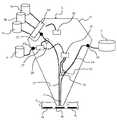
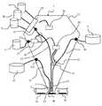
図1に、流体力学流動閉じ込めを使用した連続的化学法を実行するためのマイクロ流体プローブ1の概略斜視図を示す。 FIG. 1 shows a schematic perspective view of a microfluidic probe 1 for performing continuous chemistry using hydrodynamic fluid confinement.
マイクロ流体プローブ1は、ロボット・アーム3に取り付けられたマイクロ流体プローブ・ヘッド2を含む。ロボット・アーム3は、マイクロ流体プローブ・ヘッド2を特定の位置、特に付着領域4aないし4gのそれぞれの上方に位置決めするように構成されている。マイクロ流体プローブ1は、任意の三次元の動きを行うように、さらにx、yおよびz位置決めステージを組み込むことが好ましい。特に、マイクロ流体プローブ1は、連続的化学法を実行するように構成される。 The microfluidic probe 1 includes a microfluidic probe head 2 attached to the robot arm 3. The robot arm 3 is configured to position the microfluidic probe head 2 at a specific position, particularly above each of the
マイクロ流体プローブ・ヘッド2は、給液部5aないし5cと、スペーサ供給部6と、廃棄部7とに流体接続される。給液部5aないし5cは、マイクロ流体プローブ・ヘッド2に異なる液体、特に、生化学物質を含む液体を供給する。スペーサ供給部6は、マイクロ流体プローブ・ヘッド2に油を供給する。廃棄部7は、マイクロ流体プローブ・ヘッド2から廃液を回収する。 The microfluidic probe head 2 is fluidly connected to the liquid supply units 5a to 5c, the
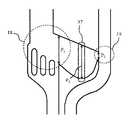
図2に、流体流動と流体力学的流動閉じ込めの形成とを示す、マイクロ流体プローブ・ヘッド2の第1の実施形態の部分図を示す。 FIG. 2 shows a partial view of a first embodiment of the microfluidic probe head 2 showing fluid flow and the formation of hydrodynamic flow confinement.
一般に、流体力学的流動閉じ込め(Hydrodynamic flow confinement:HFC)は、注入液体の層流が、バックグラウンド液体を含む液体槽内に空間的に閉じ込められる現象に関する。以下で詳述するように、本発明の各実施形態は流体力学流動閉じ込めに、都合よく依存する。例示のためであるが、本明細書に記載の各実施形態は主として流体力学的流動閉じ込めを前提とする。例えば、図2の実施形態では、注入微小流路が注入液を注入流量で液体槽内に注入し、吸引微小流路が吸引流量で注入液とバックグラウンド液体の一部とを吸引する。吸引流量を注入流量よりも高く維持することにより、注入路から吸引路への注入液の層流が形成され、周囲の液体槽内の体積内に閉じ込められる。 In general, hydrodynamic flow confinement (HFC) relates to the phenomenon in which the laminar flow of the injected liquid is spatially confined in a liquid bath containing a background liquid. As detailed below, each embodiment of the invention conveniently relies on hydrodynamic fluid confinement. For illustration purposes, each embodiment described herein presupposes hydrodynamic fluid confinement. For example, in the embodiment of FIG. 2, the injection microchannel injects the injection liquid into the liquid tank at the injection flow rate, and the suction microchannel sucks the injection liquid and a part of the background liquid at the suction flow rate. By keeping the suction flow rate higher than the injection flow rate, a laminar flow of the injection liquid from the injection passage to the suction passage is formed and confined in the volume in the surrounding liquid tank.
図2の実施形態では、付着領域4aないし4cは、付着領域4aないし4cが浸液10で覆われるように、少なくとも部分的に浸液10で満たされたペトリ皿9などの底面8上に配置されている。例えば、付着領域4aないし4cは、細胞や組織などの生物および生化学物質、またはウィルスもしくはバクテリアあるいはその両方の感染もしくはアレルギーを検出するデバイス(例えばチップ)、あるいはその両方を含み得る。 In the embodiment of FIG. 2, the
マイクロ流体プローブ・ヘッド2は、端面12を有する本体11を含む。本体11には、第1の流路13と第2の流路14とが形成されている。端面12には、第1の開口15と第2の開口16とが形成されている。第1および第2の開口15、16は、第1および第2の流路13、14にそれぞれ流体接続されている。例えば、第1と第2の開口15、16間の距離T1は、2.0mm未満、好ましくは1.5mm未満、より好ましくは1.0mm未満である。The microfluidic probe head 2 includes a
マイクロ流体プローブ・ヘッド2の本体11は、筐体または支持体の役割を果たす。本体11に組み込まれたすべての要素、部分またはデバイスあるいはこれらの組合せは、(例えばリソグラフィを使用して)オンチップで製造されてもよく、本体11とともに移動可能である。 The
本体11内部には流体バイパス17が配置されている。流体バイパス17は、第1の流路13と第2の流路14とを接続するように、第1のバイパス合流部18で第1の流路13と流体接続され、第2のバイパス合流部19で第2の流路14と流体接続されている。 A
マイクロ流体プローブ・ヘッド2は、図2の付着領域4bの上方に位置決めされる。マイクロ流体プローブ・ヘッド2の端面12は、端面12と付着領域4bとの間の距離が1ないし100μm、好ましくは1.5ないし90μm、より好ましくは2ないし80μmとなるように、付着領域4bから離間している。この距離で、端面12は付着領域4aないし4cを覆う浸液10に浸漬される。スペーサ20によって分離された液体体積23a、23bを含む個別液体体積の配列が、第1の流路13を介して第1のバイパス合流部18に給送され、そこでブロッキング要素21がスペーサ20を流体バイパス17内に方向変更させる。 The microfluidic probe head 2 is positioned above the
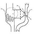
スペーサ20、特に油相を含むスペーサが付着領域4aないし4cと接触した場合、付着領域4aないし4cの表面特性が変化する可能性があり、付着領域4aないし4cが汚染される可能性があり、流体力学的流動閉じ込めの安定性が破壊され、それによって必要な付着領域4aないし4cにおける液体体積の付着が妨げられる可能性がある。特に、付着領域4aないし4c上のタンパク質などの生化学物質、細胞、生物組織が、スペーサ20と接触することによって変性または損傷あるいはその両方を受ける可能性がある。一方、脂質、治療用分子、ホルモン、無極性色素またはトレーサなどの親油性検体は、スペーサ20によって運び去られる可能性がある。また、第1の開口15を介してスペーサ20が排出される場合、スペーサ20が下の物体に剪断応力を加える可能性があり、それによってそれらの物体に損傷または、ずれ、あるいはその両方を起こす可能性がある。 When the
液体体積の配列のうちの液体体積23a、23bを分離するスペーサ20を第1の流路13から除去することによって、スペーサ20が付着領域4aないし4cに達するのが防止される一方、スペーサ20が除去された状態の個別液体体積の配列である個別液体体積の自由配列が第1の開口15に向けて給送される。動作時、閉じ込め体積22のみ、したがって個別液体体積の自由配列の層流Cのみが、付着領域4aないし4cに接触する。 By removing the
個別液体体積の自由配列は、第1の流量Q1で第1の開口15を通って浸液10中に排出する。同時に、浸液10の一部と、浸液10中に排出された個別液体体積の自由配列とが、第2の開口16を通って第2の流路14内に第2の流量Q2で吸引される。例えば、第1および第2の流量Q1、Q2は、対応するポンプ(図示せず)を使用して生じさせることができる。Individual liquid volume of the free sequence is discharged into the first flow rate Q1 at the first immersion through the
第2の流量Q2が第1の流量Q1を上回り、第1の流量Q1に対する第2の流量Q2の比が、例えば1.2ないし10(ただし、好ましくは1.5ないし6、より好ましくは2ないし4)である場合、第1の開口15から第2の開口16への層流Cを得ることができる。このような層流を実現することによって、流体力学的流動閉じ込めが可能になり、すなわち、層流Cは浸液10によって、第1の開口15の下から第2の開口16の下まで延びる閉じ込め体積22内に流体力学的に閉じ込められる。閉じ込め体積22の大きさと層流Cの形状とは、第1の流量Q1、第2の流量Q2、第1の流量Q1に対する第2の流量Q2の比、第1の開口と第2の開口との間の距離、または端面12とそれぞれの標的領域4aないし4cとの間の距離あるいはこれらの組合せによって規定されるが、これらには限定されない。例えば、第1の流量Q1は、1.0fL/sないし1.0mL/s、好ましくは1.0pL/sないし100nL/s、より好ましくは1.0ないし50nL/sとすることができ、第2の流量Q2は、0.2fL/sないし4.0mL/s、好ましくは2.0pL/sないし400nL/s、より好ましくは2.0ないし200nL/sとすることができる。The second flow rate Q2 exceeds the first flow rate Q1 , and the ratio of the second flow rate Q2 to thefirst flow rate Q1 is, for example, 1.2 to 10 (preferably 1.5 to 6, More preferably, in the case of 2 to 4), a laminar flow C from the
第1の液体体積23aを付着領域4bに付着させるために、マイクロ流体プローブ・ヘッド2は閉じ込め体積22が付着領域4bに接触するように位置決めされる。液体体積23aの一部または液体体積23a内で担持される物質あるいはその両方は、付着領域4bに付着するか、または付着領域4bの上部にある物質と反応するか、あるいはその両方を起こし得る。液体体積23aの残りの部分は、層流Cとともに移動し、第2の開口16を通って第2の流路14内に吸引される。 In order to attach the first
第1の液体体積23aの付着後、マイクロ流体プローブ・ヘッド2は、第2の液体体積23bを付着させるために次の付着領域4cの上方に位置決めすることができる。マイクロ流体プローブ・ヘッド2をそれぞれの付着領域の上方に位置決めし、その上に液体体積を付着させるステップは、必要な回数だけ繰り返すことができる。 After attachment of the first
図3に、図1のマイクロ流体プローブ・ヘッド2および流体接続箇所の第1の実施形態の概略断面図を示す。 FIG. 3 shows a schematic cross-sectional view of the microfluidic probe head 2 and the fluid connection portion of FIG. 1 according to the first embodiment.
マイクロ流体プローブ・ヘッド2の本体11の外部に給液部5aないし5cが配置されている。バルブ装置24が、給液部5aないし5cと流入口25とを流体接続する。給液部5aないし5cは、異なる液体を含む。給液部5aないし5cは、単一の液体、乳剤、懸濁液、または、同相の他の混合物、または例えば固体−液体、液体−気体または液体−液体の混合物などの異相の他の混合物、あるいはこれらの組合せを含んでもよい。特に、給液部5aないし5cのうちの少なくとも1つは、生化学物質を含む液体を含んでもよい。特に、給液部5aないし5cのうちの少なくとも1つは、(生)化学分析で使用される液体またはその分野に精通している者によってそのように判定され得る液体、例えば任意の有機流体または無機流体あるいはその両方、または生命体に関連する物質あるいはこれらの組合せを含み得る。したがって、給液部5aないし5cは、マイクロ流体プローブ・ヘッド2に、例えば細胞、タンパク質、DNA、薬剤、抗体、化学刺激物、または化学反応物あるいはこれらの組合せなどの、生物学的物質を含む1つまたは複数の液体を供給することができる。給液部5aないし5cによって供給される液体は、例えばその中に含まれる1つまたは複数の物質の化学組成または濃度が異なっていてもよい。給液部5aないし5cは、バルブ装置24に液体を供給する。 Liquid supply portions 5a to 5c are arranged outside the
バルブ装置24は、第1の流路13に流体接続され、給液部5aないし5cから受け取った液体を第1の流路13内に供給することができる。特に、バルブ装置24は、給液部5aないし5cからの液体のうちの1つの液体を特定の量だけ第1の流路13に選択的に供給するように構成される。マイクロ流体プローブ・ヘッド2の本体11内部に流入口制御部26が配置され、これは、バルブ装置24を制御することによって給液部5aないし5cの1つに流入口25を選択的に流体接続するように構成されている。この目的のため、バルブ装置24は、給液部5aないし5cから液体体積を流入口25を介して第1の流路13に連続的または交互に、あるいはその両方で供給し、それによって個別液体体積の自由配列を形成するように動作可能である。各個別液体体積の量と、個別液体体積の順序とは、流入口制御部26を使用して指定可能である。例えば、付着領域4aないし4gからの蛍光読み出し(対応するセンサは図示せず)を解釈して、特定の化学物質への暴露時間を制御することができる。所望の暴露時間に達した後は、バルブ装置24を使用して給液部5aないし5cが切り換えられる。 The
あるいは、1つの給液部5aのみをマイクロ流体プローブ・ヘッド2に流体接続することも可能である。この場合、複数の異なる液体ではなく、給液部5aからの液体が第1の流路13内に流れる。 Alternatively, it is also possible to fluidly connect only one liquid supply unit 5a to the microfluidic probe head 2. In this case, the liquid from the liquid supply unit 5a flows into the
マイクロ流体プローブ・ヘッド2の本体11の外部に配置されたスペーサ供給部6が、流入口27aを介してスペーサ挿入部27に流体接続され、スペーサ挿入部27に、給液部5aないし5cからの液体および浸液10のいずれとも混合しない油を供給し、それによってスペーサ20を供給するのに適合している。油の代わりに、給液部5aないし5cからの液体および浸液と混合しない、油脂、脂質、ヘキサンまたはトルエンあるいはこれらの組合せなどの他の無極性スペーサ流体を使用してもよい。このようにして、隣接するスペーサ20と液体体積との間の界面張力により液体体積を互いに分離することが容易になる。 The
個別液体体積の自由配列は、第1の流路13に沿って、スペーサ挿入部27が第1の流路13と流体接続されるスペーサ合流部28に向かって流れる。スペーサ合流部28は、流入口25と第1の流路13内の第1のバイパス合流部18との間に配置されている。スペーサ挿入部27は、スペーサ20を第1の流路13に挿入し、それによってスペーサ20により分離された個別液体体積の配列を形成するように構成されている。特に、スペーサ挿入部27によるスペーサ20の挿入は、個別液体体積の自由配列の各液体体積がスペーサ20によって互いに分離されるようなタイミングで行われる。スペーサ合流部28に単一の液体のみが給送される場合、スペーサ20はその液体を個別液体体積23a、23bに分割する。マイクロ流体プローブ・ヘッド2の本体11内部に配置された制御部29が、スペーサ挿入部27による第1の流路13へのスペーサ20の挿入を制御する。 The free arrangement of the individual liquid volumes flows along the
1つの液体体積の付着後、その液体体積の残りの部分と、回収されたスペーサ20と、浸液10の一部とが、第2の流路14を介して廃棄部7に給送される。流出口30が、マイクロ流体プローブ・ヘッド2の本体11内部に配置された第2の流路14を、本体11の外部の廃棄部7に流体接続する。廃棄部7は、回収された液体の再利用、格納、適切な処分あるいはこれらの組合せを行うように構成することができる。これに代えて、またはこれに加えて、流出口30を介して第2の流路14を、流出口30に供給された液体またはスペーサあるいはその両方を分析する分析装置に流体接続することが可能である。 After the attachment of one liquid volume, the remaining portion of the liquid volume, the recovered
マイクロ流体プローブ・ヘッド2の本体11内部の第1の流路13および第2の流路14の近傍にそれぞれ第1の検出器31と第2の検出器32とが設置されている。第1および第2の検出器31、32は両方とも、スペーサ20を検出し、特定するように構成されている。スペーサ20を検出すると、第1および第2の検出器31、32はそれぞれ第1の検出信号および第2の検出信号を生成し、それを制御部29に送信する。制御部29は、第1および第2の検出信号に基づいて、第1の流路13へのスペーサ20の挿入速度と、スペーサ20が第2の流路14を介して吸引される吸引速度とを同期させることができる。このために、制御部29はスペーサ挿入部27または上述のポンプあるいはその両方を適宜に制御してもよい。 A
特に、第1および第2の検出器31、32は、光学手段、電気手段または磁気手段あるいはこれらの組合せによってスペーサ20を検出するように構成することができる。第1および第2の検出器31、32によって、親水性および表面張力などのスペーサ20の特性の検出または測定あるいはその両方を行うことができる。 In particular, the first and
図4Aないし図4Lに、図2のマイクロ流体プローブ・ヘッド2の後続の動作ステップを示す。浸液10およびマイクロ流体プローブ・ヘッド2の本体11は図示されていない。 4A-4L show subsequent operating steps of the microfluidic probe head 2 of FIG. The
以下では、層流の実現によって流体力学的流動閉じ込めを可能にする。 In the following, the realization of laminar flow enables hydrodynamic flow confinement.
図4Aにおいて、スペーサ20a、20bによって分離された個別液体体積23aないし23cの配列が第1の流路13を介して第1のバイパス合流部18に給送される。上述のような第1の流量Q1に対する第2の流量Q2の特定の比により、第1の開口15から第2の開口16への層流Cが形成され、第1の開口15の下から第2の開口16の下まで延びる閉じ込め体積22内に浸液10によって閉じ込められる。In FIG. 4A, an array of
図4Bにおいて、第1の液体体積23aがブロッキング要素21を通過して流れ、第1の開口15を通って閉じ込め体積22内に排出され、閉じ込め体積22において第1の液体体積23aは層流Cによって第2の開口16に向かって移送される。 In FIG. 4B, the first
図4Cにおいて、第1の液体体積23aと第2の液体体積23bとを互いに分離する第1のスペーサ20aが、ブロッキング要素21によって形成された狭い部分流路を通過せずに流体バイパス17に流入する。 In FIG. 4C, the
第1のスペーサ20aが第1の流路13から除去された後、図4Cおよび図4Dに示すように、第2の液体体積23bが先行する第1の液体体積23aに向かって移動し、接触する。同時に、第1のスペーサ20aが流体バイパス17内のスペーサ流体の体積に加えられることにより、流体バイパス内部で過圧状態になる。 After the
流体バイパス17内部の過圧は、図4Dないし図4Fに示すようにバイパス合流部19で流体バイパス17から第2の流路14にスペーサ20pを放出することによって低減される。 The overpressure inside the
閉じ込め体積22内に排出された第1の液体体積23aは、層流Cとともに移動する。閉じ込め体積22は付着領域4bと表面接触しているため、第1の液体体積23aは付着領域4bと接触し、第1の液体体積23aの一部または第1の液体体積23aによって担持される物質あるいはその両方が、付着領域4aに付着するかまたは付着領域4aと反応するかあるいはその両方を起こす。図4Fに示すように、第1の液体体積23aの残りの部分が第2の開口16に達し、第2の流路14内に吸引される。 The first
図4Gないし図4Kに示すように、第1の液体体積23aに続いて、第2の液体体積23bが第1の開口15を通って閉じ込め体積22内に排出され、第2の開口16に向かって流れる。一方、マイクロ流体プローブ・ヘッド2は、閉じ込め体積22が次の付着領域4cと表面接触するように、例えばロボット・アーム3によって次の付着領域4cの上方に位置決めされる。閉じ込め体積22内の層流Cに沿って流れる間、第2の液体体積23bの一部または第2の液体体積23bによって担持される物質が、次の付着領域4cに付着するかまたは次の付着領域4cと反応するかあるいはその両方を起こす。図4Lに示すように、第2の液体体積23bの残りの部分が第2の開口16に達し、第2の流路14内に吸引される。 As shown in FIGS. 4G to 4K, following the first
図4Gおよび図4Hにおいて、第2の液体体積23bを第3の液体体積23cから分離する第2のスペーサ20bが第1のバイパス合流部18に到達し、ブロッキング要素21によって形成された狭い流路を通過せずに流体バイパス17に流入する。第3の液体体積23cは、第2の液体体積23bに向かって移動し、接触する。第1と第2の両方の液体体積23a、23bについてこれまでに説明した手順は、第3の液体体積23cにも同様に適用される。 In FIGS. 4G and 4H, a
図4Iないし図4Kに示すように、第1および第2の流量Q1、Q2は、回収された第1の液体体積23aが第2のバイパス合流部19にちょうど到着するときに、バイパスするスペーサ23pが流体バイパス17から第2の流路14に挿入されるように(例えば制御部29によって)同期させることができる。回収された第1の液体体積23aは、それによって、流出口30に向かって第2の流路14を移動する先行する液体体積から分離される。As shown in FIG. 4I to FIG 4K, the first and second flow rate Q1, Q2, the first
したがって、第2の流路14へのスペーサ20の挿入を適切に時間調整することにより、後で回収し/吸引される第1および第2の液体体積23a、23bを分離することができる。 Therefore, by appropriately adjusting the time of insertion of the
図5に、図1のマイクロ流体プローブ・ヘッド2および流体接続箇所の第2の実施形態の概略断面図を示す。 FIG. 5 shows a schematic cross-sectional view of a second embodiment of the microfluidic probe head 2 and the fluid connection portion of FIG.
マイクロ流体プローブ・ヘッド2の第2の実施形態は、図3の第1の実施形態のすべての要素を含む。加えて、本体11内部に第3の流路33が設けられ、第3の流路33に流体接続される第3の開口34が端面12に形成される。さらに、第3の流路33は、流体を収容することができる追加の廃棄部35に流出口35aを介して流体接続される。 The second embodiment of the microfluidic probe head 2 includes all the elements of the first embodiment of FIG. In addition, a
例えば対応するポンプ(図示せず)を使用して、液体が第3の開口34を通って第3の流路33に吸引されるように、第3の流路33に第3の流量Q3が適用される。吸引された液体は、第3の流路33を介して追加の廃棄部35に給送される。第1の開口15から第3の開口34への層流C’を生じさせ、維持するために、第3の流量Q3は第1の流量Q1より大きいことが好ましい。例えば、第1の流量Q1を1.0fL/sないし1.0mL/s、好ましくは1.0pL/sないし100nL/s、より好ましくは1.0ないし50nL/sとしてもよい。第1の流量Q1に対する第3の流量Q3の比を、1.2ないし10、好ましくは1.5ないし6、より好ましくは2ないし4としてもよい。第3の流量Q3は、1.2fL/sないし10mL/s、好ましくは2.0pL/sないし400nL/s、より好ましくは2.0ないし200nL/sとしてもよい。For example using a corresponding pump (not shown), so that liquid is sucked into the
さらに、第1と第2の開口15、16の間の流れよりも第1と第3の開口15、34の間の層流C’を優先させ、維持するために、このデバイスは、第1の開口15と第2の開口16との間の距離T1(図6参照)が第1の開口15と第3の開口34との間の距離T2よりも大きくなるように構成されることが好ましい。特に、距離T2は、2.0mm未満、好ましくは1.5mm未満、より好ましくは1.0mm未満とすることができる。この場合も、このような層流を実現することによって流体力学的流動閉じ込めが可能になる。Further, in order to prioritize and maintain the laminar flow C'between the first and
第1と第3の開口15、34の間に配置された閉じ込め体積22により、スペーサ20の回収のために第2の流路14を主として使用することができる。付着領域4bないし4dにそれぞれ付着しない液体体積23aないし23cの残りの部分は、第3の流路33を介して回収することができる。したがって、スペーサ20と液体体積23aないし23cの残りの部分の回収は、異なる場所で別々に行われる。 The
図6に、マイクロ流体プローブ・ヘッド2の第2の実施形態を使用した流体流動と流体力学的流動閉じ込めを示す。浸液10とマイクロ流体プローブ・ヘッド2の本体11は示されていない。 FIG. 6 shows fluid flow and hydrodynamic flow confinement using a second embodiment of the microfluidic probe head 2. The
スペーサ20によって分離された個別液体体積の配列は、第1の流量Q1で第1の流路13を第1の開口15に向かって流れる。第1のバイパス合流部18で、スペーサ20は液体バイパス17を介して第1の流路13から第2の流路14に方向変更される。第2の開口16において、浸液10が第2の流路14内に吸引される。吸引された浸液10と方向変更されたスペーサ20とは、第2の流路14を介して流出口30に給送される。Sequence of individual liquid volumes which are separated by a
第1の開口15から第3の開口34への層流C’が形成され、第1の開口15の下から第3の開口34の下まで延びる閉じ込め体積22’内に浸液10によって閉じ込められる。マイクロ流体プローブ・ヘッド2は、閉じ込め体積36が付着領域4と表面接触するように位置決めされる。 A laminar flow C'from the
液体体積23aが閉じ込め体積22’内部の層流C’とともに移動する間、液体体積23aの一部または液体体積23によって担持される物質あるいはその両方が、付着領域4に付着し、または付着領域4の上部にある物質と反応し、あるいはその両方を起こす。 While the
個別液体体積23aないし23cの配列をそれぞれの付着領域4に付着させるために、マイクロ流体プローブ・ヘッド2を位置決めし、液体体積23aの一部または液体体積23によって担持される物質あるいはその両方を付着させる動作ステップは、任意に繰り返すことができる。 In order to attach the sequences of the
図7ないし図9に、3つの異なる実施形態によるマイクロ流体プローブ・ヘッド2の一部を図3または図5の拡大図VII、VIII、IXで示す。特に、第1および第2の流路9、11の一部と、ブロッキング要素21と、流体バイパス18が示されている。 7-9 show some of the microfluidic probe heads 2 according to three different embodiments in enlarged views VII, VIII, IX of FIG. 3 or FIG. In particular, parts of the first and
3つの実施形態のすべてにおいて、ブロッキング要素21aないし21cはそれぞれが幅Wと、異なる長さL1ないしL3とを有する3つの棒状に形成されている。例えば、Wは5ないし80μmであり、L1は120ないし160μmであり、L2は80ないし120μmであり、L3は40ないし80μmである。2つの隣接するブロッキング要素21間または第1の流路13の内壁間あるいはその両方に、部分流路36が形成され、それぞれの部分流路36の幅は、ブロッキング要素21aないし21c同士の間または第1の流路13の内壁との間あるいはその両方で距離Dである。例えば、Dは5ないし30μmである。In all three embodiments, the blocking
スペーサの粘度が液体体積23aないし23cの粘度よりも高い場合、スペーサ20は、スペーサと液体体積との間の界面張力により、部分流路36には流入せず、ブロッキング要素21aないし21cの前面から方向変更される。したがって、ブロッキング要素21aないし21cは、スペーサ20を第1の流路13から流体バイパス17に方向変更させることができる一方、液体体積23aないし23cは部分流路36を流れる。 When the viscosity of the spacer is higher than the viscosity of the
3つの実施形態のすべてにおいて、第1の流路13は、スペーサ合流部28と第1のバイパス合流部18との間で直径A1を有する。第1の流路13は、ブロッキング要素21の位置において最大直径A2にまで広がっている。第1の開口15までのブロッキング要素21の下流で、第1の流路13は先細りとなり、第1の開口15で直径A3となっている。例えば、A1は50ないし200μmであり、A2は70ないし400μmであり、A3は20ないし100μmである。In all three embodiments, the
第2の流路14は、第2の開口16において直径B1を有し、残り部分において直径B2を有する。B1とB2とは異なっていても等しくてもよい。例えば、B1とB2の両方がそれぞれ25μmないし150μmである。The
図7において、流体バイパス17は、第1のバイパス合流部18において幅P1を有し、第2のバイパス合流部19に向かって連続的に先細りになって幅P2となり、それによって第2のバイパス合流部19での圧力を増大させる。例えば、P1は50ないし500μmであり、P2は10ないし100μmである。7, the
図8において、流体バイパス17の幅は第1のバイパス合流部18におけるP1から面37においてP3に増大し、次に第2のバイパス合流部19においてP2に減少する。このようにして、スペーサを収容するための流体バイパス17のより大きな収容容積が設けられる。例えば、P3は100ないし1000μmである。In FIG. 8, the width of the
図9において、流体バイパス17の幅P1は、面38までは一定であり、第2のバイパス合流部19でP2に減少する。これに加え、またはこれに代えて、圧力を増大させるために、第2の流路14は第2のバイパス合流部19で幅B3に狭められる。例えばB3は20ないし80μmである。In FIG. 9, the width P1 of the
流体バイパス17の3つの実施形態のすべてにおいて、第2のバイパス合流部19での圧力は、幾何形状により増大する。かくして、スペーサ20を第2の流路14内に漏洩させるのではなく、第2の流路14内に挿入することが可能になる。 In all three embodiments of the
提案のマイクロ流体プローブ・ヘッドを含む提案の方法およびマイクロ流体プローブは、スペーサによって分離された複数の液体体積の連続付着を可能にするとともに、スペーサが付着領域に達するのを防ぐためにユーザがスペーサを実質的に除去することができるようにする。特に、マイクロ流体プローブまたはマイクロ流体プローブ・ヘッドあるいはその両方が付着領域に物理的に接触するのを回避することができる。 The proposed method, including the proposed microfluidic probe head, and the microfluidic probe allow the user to attach spacers to allow continuous attachment of multiple liquid volumes separated by spacers and to prevent the spacers from reaching the attachment area. Allows it to be substantially removed. In particular, it is possible to avoid physical contact of the microfluidic probe and / or microfluidic probe head with the adhesion region.
提案のマイクロ流体プローブ・ヘッドを含む提案の方法およびマイクロ流体プローブは、表面上で免疫組織化学法の局所的な実行に適用可能である。固定化細胞、ホルマリン固定組織切片または凍結組織あるいはこれらの組合せに対して、複数の液体を順次に給送することができる。特に、疾病マーカーの存在(または不在)を示す比色信号を発生するために、間欠的バッファ洗浄ステップを使用して生体表面を一次抗体、ビオチン標識二次抗体、またはストレプトアビジン/HRPあるいはこれらの組合せに順次に暴露することができる。 The proposed method, including the proposed microfluidic probe head, and the microfluidic probe are applicable on the surface to the local practice of immunohistochemistry. Multiple liquids can be sequentially fed to immobilized cells, formalin-fixed tissue sections or frozen tissues, or a combination thereof. In particular, intermittent buffer cleaning steps are used to surface the body surface with primary antibodies, biotin-labeled secondary antibodies, or streptavidin / HRP or these to generate colorimetric signals indicating the presence (or absence) of disease markers. The combination can be exposed sequentially.
提案のマイクロ流体プローブ・ヘッドを含む提案の方法およびマイクロ流体プローブは、空間および試薬使用に関して高い効率を必要とする表面ベースの免疫学的検定に適用可能であり、特に、大量生産におけるバッチ処理に適用可能である。特に、マイクロ流体プローブに1つの抗体溶液を装填し、その後除去する動作ステップを繰り返すことによって、例えばアレルギー反応の研究のため、またはウィルス感染またはバクテリア感染あるいはその両方を検出するために、異なる種類のタンパク質または抗体あるいはその両方を表面にパターニングすることが可能である。提案の技術は、これらの検定に対する試薬使用および時間の要件を減少可能である。 The proposed method and microfluidic probe, including the proposed microfluidic probe head, are applicable for surface-based immunoassays that require high efficiency with respect to space and reagent use, especially for batch processing in mass production. Applicable. In particular, different types of microfluidic probes can be loaded with one antibody solution and then removed by repeating the operating steps, eg, for the study of allergic reactions, or for detecting viral and / or bacterial infections. It is possible to pattern proteins and / or antibodies on the surface. The proposed technique can reduce reagent use and time requirements for these tests.
提案のマイクロ流体プローブ・ヘッドを含む提案の方法およびマイクロ流体プローブは、表面上に固定された細胞に一連の化学刺激パルスを送り、その表面を液体部分の配列に暴露することによる、セクレトーム解析に適用可能である。マイクロ流体プローブは、さらに、与えられた刺激に対する細胞の反応を取り出すためにも使用可能である。 The proposed method, including the proposed microfluidic probe head, and the microfluidic probe are used for secretome analysis by sending a series of chemical stimulation pulses to cells immobilized on a surface, exposing the surface to an array of liquid moieties. Applicable. Microfluidic probes can also be used to extract the cellular response to a given stimulus.
より一般的には、本発明について特定の実施形態を参照しながら説明したが、当業者は、本発明の範囲を逸脱することなく、様々な変更を加えることが可能であり、均等物で代用可能であることがわかるであろう。さらに、本発明の範囲を逸脱することなく、本発明の教示に特定の状況を適応させるために多くの変更を加えることができる。したがって、本発明は、開示した特定の実施形態に限定されることを意図しておらず、本発明は添付の特許請求の範囲に含まれるすべての実施形態を含むことを意図している。 More generally, the present invention has been described with reference to specific embodiments, but those skilled in the art can make various modifications without departing from the scope of the invention and substitute equivalents. You will find that it is possible. Moreover, many modifications can be made to adapt a particular situation to the teachings of the invention without departing from the scope of the invention. Therefore, the present invention is not intended to be limited to the specified embodiments disclosed, and the present invention is intended to include all embodiments included in the appended claims.
1 マイクロ流体プローブ
2 マイクロ流体プローブ・ヘッド
3 ロボット・アーム
4a−4h 付着領域
5a、5b、5c 給液部
6 スペーサ供給部
7 廃棄部
8 底面
9 ペトリ皿
10 浸液
11 本体
12 端面
13 第1の流路
14 第2の流路
15 第1の開口
16 第2の開口
17 流体バイパス
18 第1のバイパス合流部
19 第2のバイパス合流部
20、20a−20c スペーサ
21、21a−21c ブロッキング要素
22、22’ 閉じ込め体積
23a−23c 液体体積
24 バルブ装置
25 流入口
26 流入口制御部
27 スペーサ挿入部
27a 流入口
28 スペーサ合流部
29 制御部
30 流出口
31 第1の検出器
32 第2の検出器
33 第3の流路
34 第3の開口
35 追加の廃棄部
35a 流出口
36 部分流路
37 面
38 面
A1、A2、A3 直径
B1、B2、B3 直径
C、C’ 層流
D 距離
L1、L2、L3 長さ
P1、P2、P3 幅
Q1、Q2、Q3 流量
T1、T2 距離
W 幅1 Microfluidic probe 2 Microfluidic probe head 3
Claims (14)
Translated fromJapanese流入口および流出口と、
第1の流路および第2の流路と、
前記第1の流路と前記第2の流路とを互いに接続する流体バイパスとを含み、
前記第1の流路は、個別液体体積の前記配列を前記流入口から付着領域に向けて給送するように構成され、
前記流体バイパスは、前記第1の流路から前記スペーサを除去することによってスペーサのない個別液体体積の自由配列が得られるように、前記第1の流路と前記第2の流路とを接続し、
前記第1の流路は、個別液体体積の前記自由配列を前記付着領域に給送するように構成され、
前記第2の流路は、除去された前記スペーサを前記流体バイパスから前記流出口に給送するように構成され、
前記第1の流路と前記第2の流路と前記流体バイパスとを含み、浸液中に浸漬するように構成された端面を有する本体と、
前記端面に形成され、前記第1の流路に流体接続された第1の開口と、
前記端面に形成され、前記第2の流路に流体接続された第2の開口とをさらに含み、
前記流体バイパスは、前記第1の開口の上流で前記第1の流路に接続し、
前記マイクロ流体プローブ・ヘッドは、
個別液体体積の前記自由配列を前記第1の開口と前記第1の流路とを介して第1の流量で給送し、
個別液体体積の前記自由配列を前記付着領域から前記浸液の一部とともに、前記第2の開口と前記第2の流路とを介して第2の流量で吸引するように構成され、
給送された個別液体体積の前記自由配列を前記浸液内に閉じ込めるように、前記第2の流量は前記第1の流量より大きい、マイクロ流体プローブ・ヘッド。A microfluidic probe head for processing an array of individual liquid volumes separated by spacers.
Inlet and outlet,
The first flow path and the second flow path,
Includes a fluid bypass connecting the first flow path and the second flow path to each other.
The first flow path is configured to feed the array of individual liquid volumes from the inlet to the adhesion region.
The fluid bypass connects the first flow path and the second flow path so that a free arrangement of individual liquid volumes without spacers can be obtained by removing the spacer from the first flow path. And
The first flow path is configured to feed the free arrangement of individual liquid volumes to the adhesion region.
The second flow path is configured to feed the removed spacer from the fluid bypass to the outlet.
A main body including the first flow path, the second flow path, and the fluid bypass, and having an end face configured to be immersed in the immersion liquid.
A first opening formed on the end face and fluidly connected to the first flow path,
Further including a second opening formed on the end face and fluidly connected to the second flow path.
The fluid bypass connects to the first flow path upstream of the first opening and
The microfluidic probe head
The free arrangement of individual liquid volumes is fed at a first flow rate through the first opening and the first flow path.
The free arrangement of individual liquid volumes is configured to be aspirated from the adhesion region with a portion of the immersion liquid at a second flow rate through the second opening and the second flow path.
A microfluidic probe head in whichthe second flow rate is greater than the first flow rate so as to confine the free arrangement of the fed individual liquid volumes within the immersion liquid .
前記第3の流路は、個別液体体積の前記自由配列を前記付着領域から前記追加の流出口に給送するように構成された、請求項1ないし3のいずれかに記載のマイクロ流体プローブ・ヘッド。Further including an additional outlet and a third channel,
The microfluidic probe according to any one of claims 1 to3 , wherein the third flow path is configured to feed the free arrangement of individual liquid volumes from the attachment region to the additional outlet. head.
前記端面に形成され、前記第3の流路に流体接続された第3の開口をさらに含み、
前記流体バイパスは前記第1の開口の上流で前記第1の流路に接続し、前記マイクロ流体プローブ・ヘッドは、
個別液体体積の前記自由配列を前記第1の開口と前記第1の流路とを介して供給し、
前記浸液の一部を前記付着領域から前記第2の開口と前記第2の流路とを介して吸引し、
個別液体体積の前記自由配列を前記浸液の一部とともに前記付着領域から前記第3の開口と前記第3の流路とを介して吸引するように構成された、請求項4に記載のマイクロ流体プローブ・ヘッド。
It said body includessaid thirdchannel,
Is formed on the endsurface, further comprisinga third openingwhich is fluidly connectedto the third channel,
The fluid bypass connects to the first flow path upstream of the first opening, and the microfluidic probe head
The free arrangement of individual liquid volumes is supplied via the first opening and the first flow path.
A part of the immersion liquid is sucked from the adhesion region through the second opening and the second flow path.
The micro according to claim 4, wherein the free arrangement of individual liquid volumes is configured to be sucked together with a part of the immersion liquid from the adhesion region through the third opening and the third flow path. Fluid probe head.
請求項1ないし11のいずれかのマイクロ流体プローブ・ヘッドと、
前記マイクロ流体プローブ・ヘッドの前記流入口に流体接続可能な複数の給液部と、
前記流入口を前記複数の給液部のうちの1つに選択的に流体接続するための制御部とを含む、マイクロ流体プローブ。A microfluidic probe for processing an array of individual liquid volumes separated by spacers.
With the microfluidic probe head according to any one of claims 1 to11 .
A plurality of liquid supply units capable of fluid connection to the inflow port of the microfluidic probe head, and
A microfluidic probe comprising a control unit for selectively fluid-connecting the inflow port to one of the plurality of liquid supply units.
個別液体体積の前記配列を第1の流路を介して流入口から付着領域に向けて給送することと、
前記個別液体体積を互いに分離する前記スペーサを、前記第1の流路と第2の流路とを接続する流体バイパスを介して前記第1の流路から除去することによってスペーサのない個別液体体積の自由配列を得ることと、
個別液体体積の前記自由配列を前記付着領域に給送することと、
除去された前記スペーサを前記流体バイパスから前記第2の流路を介して流出口に給送することとを含み、
個別液体体積の前記配列を給送することと、前記スペーサを除去することと、個別液体体積の前記自由配列を給送することと、除去された前記スペーサを給送することとが、請求項1に記載のマイクロ流体プローブ・ヘッドを使用して行われる方法。A method of processing an array of individual liquid volumes separated by spacers.
Feeding the array of individual liquid volumes from the inlet to the adhesion region via a first flow path,
The individual liquid volume without spacers by removing the spacers that separate the individual liquid volumes from each other from the first flow path via a fluid bypass connecting the first flow path and the second flow path. To get a free array of
Feeding the free arrangement of individual liquid volumes to the adhesion region,
Including feeding the removed spacer from the fluid bypass to the outlet via the second flow path.
It is claimed that feeding the array of individual liquid volumes, removing the spacers, feeding the free array of individual liquid volumes, and feeding the removed spacers. The methodperformed using the microfluidic probe head according to 1 .
13. The method of claim13 , wherein the array of individual liquid volumes fed through the first flow path comprises an individual volume of at least two different liquids.
Applications Claiming Priority (3)
| Application Number | Priority Date | Filing Date | Title |
|---|---|---|---|
| EP15155054.8 | 2015-02-13 | ||
| EP15155054 | 2015-02-13 | ||
| PCT/EP2016/052995WO2016128543A1 (en) | 2015-02-13 | 2016-02-12 | Microfluidic probe head for processing a sequence of liquid volumes separated by spacers |
Publications (2)
| Publication Number | Publication Date |
|---|---|
| JP2018505403A JP2018505403A (en) | 2018-02-22 |
| JP6796067B2true JP6796067B2 (en) | 2020-12-02 |
Family
ID=52577632
Family Applications (1)
| Application Number | Title | Priority Date | Filing Date |
|---|---|---|---|
| JP2017535862AActiveJP6796067B2 (en) | 2015-02-13 | 2016-02-12 | Microfluidic probe head for processing arrays of liquid volumes separated by spacers |
Country Status (6)
| Country | Link |
|---|---|
| US (2) | US10639631B2 (en) |
| JP (1) | JP6796067B2 (en) |
| CN (1) | CN107295796A (en) |
| DE (1) | DE112016000223T5 (en) |
| GB (1) | GB2553674B (en) |
| WO (1) | WO2016128543A1 (en) |
Families Citing this family (6)
| Publication number | Priority date | Publication date | Assignee | Title |
|---|---|---|---|---|
| US10639631B2 (en)* | 2015-02-13 | 2020-05-05 | International Business Machines Corporation | Microfluidic probe head for processing a sequence of liquid volumes separated by spacers |
| US10006838B2 (en) | 2015-08-04 | 2018-06-26 | Adam Tokarski | Sampling device |
| US10434510B2 (en) | 2017-05-06 | 2019-10-08 | International Business Machines Corporation | Microfluidic probe with bypass and control channels |
| JP2019170363A (en)* | 2018-03-29 | 2019-10-10 | 東ソー株式会社 | Reaction apparatus and reaction method of target molecule |
| EP3861356A4 (en) | 2018-10-01 | 2022-07-06 | Polyvalor, Limited Partnership | SYSTEM AND PROCEDURE FOR LIQUID DISPENSING |
| US11458467B2 (en)* | 2019-08-06 | 2022-10-04 | Bio-Rad Laboratories Inc. | Structures to define flow confinement shape and confinement stability with uniform aspiration |
Family Cites Families (16)
| Publication number | Priority date | Publication date | Assignee | Title |
|---|---|---|---|---|
| BE788754A (en)* | 1971-10-13 | 1973-03-13 | Technicon Instr | |
| AU2003216175A1 (en)* | 2002-02-04 | 2003-09-02 | Colorado School Of Mines | Laminar flow-based separations of colloidal and cellular particles |
| EP2282214B1 (en) | 2002-05-09 | 2022-10-05 | The University of Chicago | Device and method for pressure-driven plug transport and reaction |
| CN102357352B (en) | 2004-01-26 | 2015-08-12 | 哈佛大学 | Fluid delivery system and method |
| US20070141593A1 (en) | 2005-08-22 | 2007-06-21 | Lee Linda G | Apparatus, system, and method using immiscible-fluid-discrete-volumes |
| WO2008130623A1 (en)* | 2007-04-19 | 2008-10-30 | Brandeis University | Manipulation of fluids, fluid components and reactions in microfluidic systems |
| US8622987B2 (en)* | 2008-06-04 | 2014-01-07 | The University Of Chicago | Chemistrode, a plug-based microfluidic device and method for stimulation and sampling with high temporal, spatial, and chemical resolution |
| US8061187B2 (en)* | 2009-04-27 | 2011-11-22 | Battelle Memorial Institute | Lossless droplet transfer of droplet-based microfluidic analysis |
| WO2011067670A2 (en) | 2009-12-03 | 2011-06-09 | Owe Owar | Pipettes, methods of use, and methods of stimulating an object of interest |
| US8312780B2 (en) | 2010-06-25 | 2012-11-20 | Mettler-Toledo Ag | Sampling device and method |
| DE102010032203A1 (en) | 2010-07-26 | 2012-01-26 | MAX-PLANCK-Gesellschaft zur Förderung der Wissenschaften e.V. | Method and apparatus for the passive separation and sorting of drops, in particular in a microfluidic system, by using non-optical markers for reactions within the drops |
| US8365616B1 (en) | 2010-09-16 | 2013-02-05 | Wolcott Duane K | Sampling probe for solutions containing soluble solids or high concentrations of dissolved solids |
| CN203517653U (en) | 2010-10-28 | 2014-04-02 | Iq集团私人有限公司 | Light emitting diode illumination module whose module housing is used as radiator |
| TWI532530B (en) | 2010-10-29 | 2016-05-11 | 萬國商業機器公司 | Multilayer microfluidic probe head with immersion channels and fabrication thereof |
| WO2013183013A1 (en) | 2012-06-06 | 2013-12-12 | De Oliva Novo Pedro Jose | Autonomous and programmable sequential flow of solutions in capillary microfluidics |
| US10639631B2 (en) | 2015-02-13 | 2020-05-05 | International Business Machines Corporation | Microfluidic probe head for processing a sequence of liquid volumes separated by spacers |
- 2016
- 2016-02-11USUS15/041,141patent/US10639631B2/enactiveActive
- 2016-02-12WOPCT/EP2016/052995patent/WO2016128543A1/ennot_activeCeased
- 2016-02-12GBGB1713658.1Apatent/GB2553674B/enactiveActive
- 2016-02-12DEDE112016000223.8Tpatent/DE112016000223T5/enactivePending
- 2016-02-12CNCN201680010095.2Apatent/CN107295796A/enactivePending
- 2016-02-12JPJP2017535862Apatent/JP6796067B2/enactiveActive
- 2020
- 2020-03-30USUS16/835,153patent/US10926258B2/enactiveActive
Also Published As
| Publication number | Publication date |
|---|---|
| GB2553674A (en) | 2018-03-14 |
| JP2018505403A (en) | 2018-02-22 |
| WO2016128543A1 (en) | 2016-08-18 |
| DE112016000223T5 (en) | 2017-09-07 |
| CN107295796A (en) | 2017-10-24 |
| US10926258B2 (en) | 2021-02-23 |
| US10639631B2 (en) | 2020-05-05 |
| GB2553674B (en) | 2021-03-17 |
| GB201713658D0 (en) | 2017-10-11 |
| US20200230599A1 (en) | 2020-07-23 |
| US20160243549A1 (en) | 2016-08-25 |
Similar Documents
| Publication | Publication Date | Title |
|---|---|---|
| US10549276B2 (en) | Microfluidic probe head for providing a sequence of separate liquid volumes separated by spacers | |
| JP6796067B2 (en) | Microfluidic probe head for processing arrays of liquid volumes separated by spacers | |
| US7211442B2 (en) | Microfluidic system including a virtual wall fluid interface port for interfacing fluids with the microfluidic system | |
| CN102553665B (en) | Microfluidic concentration gradient droplet generating chip, generating device and application | |
| EP1905513A1 (en) | Methods and devices for sampling fluids | |
| US20060263264A1 (en) | Microfluidic system including a virtual wall fluid interface port for interfacing fluids with the microfluidic system | |
| JP2005514187A (en) | Microfluidic system including virtual wall fluidic interconnect ports for interconnecting fluids with microfluidic systems | |
| EP3366375B1 (en) | Liquid sending method using sample processing chip and liquid sending device for sample processing chip | |
| WO2007081386A2 (en) | Microfluidic devices and methods of use | |
| CN108136390B (en) | Fluid System for Executing the Test | |
| WO2010019388A2 (en) | Method and apparatus for the discretization and manipulation of sample volumes | |
| GB2464300A (en) | Microfluidic multiplexed cellular and molecular analysis device and method | |
| JP7071056B2 (en) | Liquid delivery method and liquid delivery device | |
| CN112292207A (en) | Microfabricated drop dispenser with immiscible fluids | |
| US20160310947A1 (en) | Controlling fluid micro-compartments | |
| WO2021185599A1 (en) | Microfabricated sorter with magnetic sorting stage and droplet dispenser | |
| US20020197733A1 (en) | Microfluidic system including a virtual wall fluid interface port for interfacing fluids with the microfluidic system | |
| JP2011257238A (en) | Trace droplet weighing structure, microfluidic device, and trace droplet weighing method | |
| US20170100717A1 (en) | Microfluidic Probe for Modulating Insertion of Liquid Spacers | |
| US12239984B2 (en) | Method of manipulating droplets in a channel | |
| JP2006010332A (en) | Method for forming sample solution with small capacity | |
| HK1256696B (en) | Fluidic system for performing assays |
Legal Events
| Date | Code | Title | Description |
|---|---|---|---|
| A621 | Written request for application examination | Free format text:JAPANESE INTERMEDIATE CODE: A621 Effective date:20181023 | |
| A977 | Report on retrieval | Free format text:JAPANESE INTERMEDIATE CODE: A971007 Effective date:20191025 | |
| A131 | Notification of reasons for refusal | Free format text:JAPANESE INTERMEDIATE CODE: A131 Effective date:20191119 | |
| RD12 | Notification of acceptance of power of sub attorney | Free format text:JAPANESE INTERMEDIATE CODE: A7432 Effective date:20191208 | |
| A521 | Request for written amendment filed | Free format text:JAPANESE INTERMEDIATE CODE: A821 Effective date:20191209 | |
| A521 | Request for written amendment filed | Free format text:JAPANESE INTERMEDIATE CODE: A523 Effective date:20200121 | |
| A131 | Notification of reasons for refusal | Free format text:JAPANESE INTERMEDIATE CODE: A131 Effective date:20200422 | |
| A521 | Request for written amendment filed | Free format text:JAPANESE INTERMEDIATE CODE: A523 Effective date:20200611 | |
| TRDD | Decision of grant or rejection written | ||
| A01 | Written decision to grant a patent or to grant a registration (utility model) | Free format text:JAPANESE INTERMEDIATE CODE: A01 Effective date:20201104 | |
| A61 | First payment of annual fees (during grant procedure) | Free format text:JAPANESE INTERMEDIATE CODE: A61 Effective date:20201113 | |
| R150 | Certificate of patent or registration of utility model | Ref document number:6796067 Country of ref document:JP Free format text:JAPANESE INTERMEDIATE CODE: R150 | |
| RD14 | Notification of resignation of power of sub attorney | Free format text:JAPANESE INTERMEDIATE CODE: A7434 Effective date:20201118 |