JP6793524B2 - Log analysis system and its method - Google Patents
Log analysis system and its methodDownload PDFInfo
- Publication number
- JP6793524B2 JP6793524B2JP2016214265AJP2016214265AJP6793524B2JP 6793524 B2JP6793524 B2JP 6793524B2JP 2016214265 AJP2016214265 AJP 2016214265AJP 2016214265 AJP2016214265 AJP 2016214265AJP 6793524 B2JP6793524 B2JP 6793524B2
- Authority
- JP
- Japan
- Prior art keywords
- communication
- pattern
- module
- packet
- monitoring device
- Prior art date
- Legal status (The legal status is an assumption and is not a legal conclusion. Google has not performed a legal analysis and makes no representation as to the accuracy of the status listed.)
- Expired - Fee Related
Links
Images


Classifications
- H—ELECTRICITY
- H04—ELECTRIC COMMUNICATION TECHNIQUE
- H04L—TRANSMISSION OF DIGITAL INFORMATION, e.g. TELEGRAPHIC COMMUNICATION
- H04L63/00—Network architectures or network communication protocols for network security
- H04L63/14—Network architectures or network communication protocols for network security for detecting or protecting against malicious traffic
- H04L63/1408—Network architectures or network communication protocols for network security for detecting or protecting against malicious traffic by monitoring network traffic
- H04L63/1425—Traffic logging, e.g. anomaly detection
- G—PHYSICS
- G06—COMPUTING OR CALCULATING; COUNTING
- G06F—ELECTRIC DIGITAL DATA PROCESSING
- G06F11/00—Error detection; Error correction; Monitoring
- G06F11/30—Monitoring
- G06F11/3003—Monitoring arrangements specially adapted to the computing system or computing system component being monitored
- G06F11/3006—Monitoring arrangements specially adapted to the computing system or computing system component being monitored where the computing system is distributed, e.g. networked systems, clusters, multiprocessor systems
- G—PHYSICS
- G06—COMPUTING OR CALCULATING; COUNTING
- G06F—ELECTRIC DIGITAL DATA PROCESSING
- G06F11/00—Error detection; Error correction; Monitoring
- G06F11/30—Monitoring
- G06F11/34—Recording or statistical evaluation of computer activity, e.g. of down time, of input/output operation ; Recording or statistical evaluation of user activity, e.g. usability assessment
- G06F11/3466—Performance evaluation by tracing or monitoring
- G06F11/3476—Data logging
- G—PHYSICS
- G06—COMPUTING OR CALCULATING; COUNTING
- G06F—ELECTRIC DIGITAL DATA PROCESSING
- G06F17/00—Digital computing or data processing equipment or methods, specially adapted for specific functions
- G06F17/40—Data acquisition and logging
- H—ELECTRICITY
- H04—ELECTRIC COMMUNICATION TECHNIQUE
- H04L—TRANSMISSION OF DIGITAL INFORMATION, e.g. TELEGRAPHIC COMMUNICATION
- H04L41/00—Arrangements for maintenance, administration or management of data switching networks, e.g. of packet switching networks
- H04L41/06—Management of faults, events, alarms or notifications
- H04L41/069—Management of faults, events, alarms or notifications using logs of notifications; Post-processing of notifications
- H—ELECTRICITY
- H04—ELECTRIC COMMUNICATION TECHNIQUE
- H04L—TRANSMISSION OF DIGITAL INFORMATION, e.g. TELEGRAPHIC COMMUNICATION
- H04L43/00—Arrangements for monitoring or testing data switching networks
- H04L43/04—Processing captured monitoring data, e.g. for logfile generation
- H—ELECTRICITY
- H04—ELECTRIC COMMUNICATION TECHNIQUE
- H04L—TRANSMISSION OF DIGITAL INFORMATION, e.g. TELEGRAPHIC COMMUNICATION
- H04L43/00—Arrangements for monitoring or testing data switching networks
- H04L43/04—Processing captured monitoring data, e.g. for logfile generation
- H04L43/045—Processing captured monitoring data, e.g. for logfile generation for graphical visualisation of monitoring data
- H—ELECTRICITY
- H04—ELECTRIC COMMUNICATION TECHNIQUE
- H04L—TRANSMISSION OF DIGITAL INFORMATION, e.g. TELEGRAPHIC COMMUNICATION
- H04L43/00—Arrangements for monitoring or testing data switching networks
- H04L43/12—Network monitoring probes
- H—ELECTRICITY
- H04—ELECTRIC COMMUNICATION TECHNIQUE
- H04L—TRANSMISSION OF DIGITAL INFORMATION, e.g. TELEGRAPHIC COMMUNICATION
- H04L43/00—Arrangements for monitoring or testing data switching networks
- H04L43/50—Testing arrangements
- H—ELECTRICITY
- H04—ELECTRIC COMMUNICATION TECHNIQUE
- H04L—TRANSMISSION OF DIGITAL INFORMATION, e.g. TELEGRAPHIC COMMUNICATION
- H04L63/00—Network architectures or network communication protocols for network security
- H04L63/14—Network architectures or network communication protocols for network security for detecting or protecting against malicious traffic
- H04L63/1441—Countermeasures against malicious traffic
- H04L63/145—Countermeasures against malicious traffic the attack involving the propagation of malware through the network, e.g. viruses, trojans or worms
- H—ELECTRICITY
- H04—ELECTRIC COMMUNICATION TECHNIQUE
- H04L—TRANSMISSION OF DIGITAL INFORMATION, e.g. TELEGRAPHIC COMMUNICATION
- H04L63/00—Network architectures or network communication protocols for network security
- H04L63/14—Network architectures or network communication protocols for network security for detecting or protecting against malicious traffic
- H04L63/1441—Countermeasures against malicious traffic
- H04L63/1458—Denial of Service
- G—PHYSICS
- G05—CONTROLLING; REGULATING
- G05B—CONTROL OR REGULATING SYSTEMS IN GENERAL; FUNCTIONAL ELEMENTS OF SUCH SYSTEMS; MONITORING OR TESTING ARRANGEMENTS FOR SUCH SYSTEMS OR ELEMENTS
- G05B19/00—Programme-control systems
- G05B19/02—Programme-control systems electric
- G05B19/418—Total factory control, i.e. centrally controlling a plurality of machines, e.g. direct or distributed numerical control [DNC], flexible manufacturing systems [FMS], integrated manufacturing systems [IMS] or computer integrated manufacturing [CIM]
Landscapes
- Engineering & Computer Science (AREA)
- Computer Security & Cryptography (AREA)
- General Engineering & Computer Science (AREA)
- Computer Networks & Wireless Communication (AREA)
- Signal Processing (AREA)
- Computing Systems (AREA)
- Theoretical Computer Science (AREA)
- Computer Hardware Design (AREA)
- Physics & Mathematics (AREA)
- General Physics & Mathematics (AREA)
- Quality & Reliability (AREA)
- Data Mining & Analysis (AREA)
- Mathematical Physics (AREA)
- General Health & Medical Sciences (AREA)
- Virology (AREA)
- Health & Medical Sciences (AREA)
- Databases & Information Systems (AREA)
- Software Systems (AREA)
- Data Exchanges In Wide-Area Networks (AREA)
Description
Translated fromJapanese本発明は、ログ解析システムおよびその方法に関し、例えば、プラント設備の制御システムの通信ログを解析して不正アクセスによる通信ログを抽出するログ解析システムに関する。 The present invention relates to a log analysis system and a method thereof, for example, a log analysis system that analyzes a communication log of a control system of a plant facility and extracts a communication log due to unauthorized access.
プラント設備に限らず、自動車や家電など多くの分野で、コンピュータを利用した制御システムが汎用されている。そして、IT技術の進歩により、制御システムもネットワークを介して、情報の入出力が可能になっている。一方、これに合わせて、制御システムに対するコンピュータウィルスやDoS攻撃といった不正アクセスも目立つようになっている。そこで、制御システムを不正アクセスから守る技術が種々提案されている。 Computer-based control systems are widely used not only in plant equipment but also in many fields such as automobiles and home appliances. With the progress of IT technology, control systems can also input and output information via networks. On the other hand, in line with this, unauthorized access such as computer viruses and DoS attacks on control systems has become conspicuous. Therefore, various techniques for protecting the control system from unauthorized access have been proposed.
制御システムに対する大量の通信ログの1つ1つをチェックして、不正アクセスを検知することは容易ではない。そこで、特許文献1には、通信ログを処理すべきテンプレートを複数用意し、通信ログがどのテンプレートにマッチしたかによって、不正アクセス防止のために確認すべき通信ログ量を削減できる技術が開示されている。 It is not easy to detect unauthorized access by checking each of a large amount of communication logs for the control system. Therefore,
しかしながら、特許文献1に記載された発明では、制御システムの運用形態によって、制御システムの通信ログのパターンが大きく変化するため、そもそもテンプレートによって、不正アクセスから制御システムを防衛するには限界があった。ここでパターンとは、例えば周波数に着目した通信ログの特徴とする。また通信におけるパターンを通信パターンとする。 However, in the invention described in
本発明は、不正アクセスから制御システムをより効果的に防衛することできるログ解析システムおよびその方法を提案しようとするものである。 The present invention attempts to propose a log analysis system and a method thereof that can more effectively protect the control system from unauthorized access.
かかる課題を解決するために本発明においては、制御装置の通信ログを解析するログ解析システムにおいて、通信ログに対応する通信パケットをネットワークから受信するネットワーク装置と、ネットワーク装置への通信を監視する監視装置と、を備え、監視装置は、通信パケットの通信パターンと不正アクセスのない状態の通信におけるパターンである定常パターンとの差分を求め、差分に基づいて通信パケットを復元し、復元された通信パケットを報知するようにした。 In order to solve this problem, in the present invention, in the log analysis system that analyzes the communication log of the control device, the network device that receives the communication packet corresponding to the communication log from the network and the monitoring that monitors the communication to the network device. The monitoring device includes a device, obtains a difference between the communication pattern of the communication packet and a stationary pattern which is a pattern in communication without unauthorized access, restores the communication packet based on the difference, and restores the restored communication packet. Was made to notify.
また本発明においては、制御装置の通信ログを解析するログ解析システムにおけるログ解析方法において、ログ解析システムは、通信ログに対応する通信パケットをネットワークから受信するネットワーク装置と、ネットワーク装置への通信を監視する監視装置と、備え、監視装置が、通信パケットの通信パターンと不正アクセスのない状態の通信におけるパターンである定常パターンとの差分を求める第1のステップと、監視装置が、差分に基づいて通信パケットを復元する第2のステップと、監視装置が、復元された通信パケットを報知する第3のステップと、を備えるようにした。 Further, in the present invention, in the log analysis method in the log analysis system that analyzes the communication log of the control device, the log analysis system communicates with the network device that receives the communication packet corresponding to the communication log from the network and the network device. The first step in which the monitoring device to be monitored and the monitoring device are provided to obtain the difference between the communication pattern of the communication packet and the steady pattern which is the pattern in the communication without unauthorized access, and the monitoring device are based on the difference. The monitoring device is provided with a second step of restoring the communication packet and a third step of notifying the restored communication packet.
本発明によれば、不正アクセスから制御システムをより効果的に防衛することできるログ解析システムおよびその方法を実現できる。 According to the present invention, it is possible to realize a log analysis system and a method thereof that can more effectively protect the control system from unauthorized access.
以下図面について、本発明の一実施の形態を詳述する。なお、これにより本発明が限定されるものではない。 Hereinafter, one embodiment of the present invention will be described in detail with reference to the drawings. It should be noted that this does not limit the present invention.
(1)第1の実施の形態
(1−1)本実施の形態によるログ解析システムの構成
図1は、本実施の形態によるログ解析システムの機能構成を示す。このシステムは、ネットワーク装置20と、制御装置10の通信ログを監視する監視装置30と、イントラネットなどのネットワーク40とを備える。(1) First Embodiment (1-1) Configuration of Log Analysis System According to This Embodiment FIG. 1 shows a functional configuration of a log analysis system according to the present embodiment. This system includes a
制御装置10は、プラント設備などの制御対象を制御する要素であって、1つに限られず、図1に示すように101〜10nのように複数存在する。制御装置10は、具体的には、コンピュータ、コントローラ(MPU)などである。コンピュータには、サーバ計算機、クライアント計算機を含む。制御装置10は、所定の制御処理を行う制御処理モジュール101(1011〜101n)およびネットワーク40やネットワーク装置20と通信する通信モジュール102(1021〜102n)を備える。
ネットワーク装置20は、ログ解析システムのネットワーク制御を行うルータやレイヤ2スイッチなどの装置であり、パケット複製モジュール201、第1通信モジュール202、監視装置30と通信を行う第2通信モジュール203および第3通信モジュール204を備える。モジュールは、制御機能を実現する単位であって、プログラム、および/または、ハードウェアによって実現される。 The
パケット複製モジュール201は、ネットワーク装置20に入力される通信パケット1200(図12参照)を複製し、第1通信モジュール202は、ネットワーク40と通信し、第2通信モジュールは監視装置30と通信し、第3通信モジュール204は制御装置10nと通信する。なお、ネットワーク装置20は、4つ以上の通信モジュールを備えていてもよく、例えば第4通信モジュールは図示せぬ制御装置102と通信する。The
監視装置30は、プラント設備などの制御システムの通信ログを監視する装置であり、通信モジュール301、通信パケット取得モジュール302、パターン抽出モジュール303、異常パターン抽出モジュール304、異常パケット復元モジュール305、出力モジュール306、通信パケット格納モジュール307、定常パターン格納モジュール308、異常パケット格納モジュール309およびモード管理モジュール310を備える。 The
通信モジュール301はネットワーク装置20と通信を行い、通信パケット取得モジュール302は監視装置30に入力される通信パケット1200を取得し、パターン抽出モジュール303は通信パケット取得モジュール302が取得した通信パケット1200のパターンを抽出する。 The
異常パターン抽出モジュール304は通信パケット取得モジュール302が取得した通信パケット1200に含まれる異常パターンを抽出し、異常パケット復元モジュール305は異常パターン抽出モジュール304が抽出した異常パターンに該当する通信パケット1200を復元する。 The error pattern extraction module 304 extracts the error pattern included in the
パターンとは、複数の通信ログの組み合わせからなる、通信の態様であり、例えば、複数の通信ログをフーリエ変換することによって判別される。異常パターンとは、コンピュータウィルスやDoS攻撃など不正アクセスに伴う複数の通信ログに基づくパターンである。異常パターンは、制御システムに不正アクセスがないと想定できる環境におけるパターンと比較することによって抽出され得る。 The pattern is a mode of communication composed of a combination of a plurality of communication logs, and is determined by, for example, Fourier transforming a plurality of communication logs. The abnormal pattern is a pattern based on a plurality of communication logs associated with unauthorized access such as a computer virus or DoS attack. Anomalous patterns can be extracted by comparing with patterns in an environment where it can be assumed that the control system is free of unauthorized access.
このような環境とは、例えば、制御システムの試運転状態など制御システムの動作が通常運転状態よりも落ち着いている運転状態である。この運転状態を定常運転状態と称する。制御装置が通常運転状態(以下、運用状態としてもよい)では、制御装置の活動が活発であるから、種々の不正アクセスのおそれがあるが、制御装置が定常運転状態(以下、試運転状態としてもよい)では、通常運転状態に比較して、ほぼ不正アクセスのおそれはないか、不正アクセスのおそれは小さいと想定できる。 Such an environment is an operating state in which the operation of the control system is calmer than the normal operating state, such as a test run state of the control system. This operating state is called a steady operating state. When the control device is in the normal operation state (hereinafter, may be in the operating state), since the activity of the control device is active, there is a risk of various unauthorized access, but the control device is in the steady operation state (hereinafter, also in the test run state). In good), it can be assumed that there is almost no risk of unauthorized access or the risk of unauthorized access is small compared to the normal operating state.
この状態の通信パターンを定常運転状態に関連させて定常パターンと称する。監視モジュールは、通信パターンを定常パターンと比較することによって、通信パターンの中から異常パターンを抽出することができる。 The communication pattern in this state is referred to as a steady operation pattern in relation to the steady operation state. The monitoring module can extract an abnormal pattern from the communication pattern by comparing the communication pattern with the steady pattern.
制御システムに不正アクセスがないと想定される状態は、例えば制御装置10に必要最低限の制御コマンドが入力された状態とする(以下、制御システムの試運転時とする)。 The state in which it is assumed that there is no unauthorized access to the control system is, for example, a state in which the minimum necessary control command is input to the control device 10 (hereinafter, referred to as a test run of the control system).
通信パケット格納モジュール307は通信パケット取得モジュール302が取得した通信パケット1200を格納し、定常パターン格納モジュール308はパターン抽出モジュール303が抽出した定常時の通信パターン1300(図13参照)を格納する。 The communication packet storage module 307 stores the
異常パケット格納モジュール309は異常パケット復元モジュール305が復元した異常パケットを格納し、モード管理モジュール310は監視装置30の動作モードを管理する。動作モードには、初期モードおよび運用モードの2種類のモードがある。初期モードは定常パターンを取得するための監視装置30の動作モードであり、運用モードは異常パターンを取得するための監視装置30の動作モードである。 The abnormal
監視装置30の動作モードが、モード管理モジュール310によって初期モードに設定されると、監視装置30およびログ解析システムは試運転状態となり、監視装置30の動作モードがモード管理モジュール310によって運用モードに設定されると、監視装置30およびログ解析システムは運用状態となる。 When the operation mode of the
例えば、監視装置30の動作モードは、必要最低限の特定の制御コマンドが制御装置10に入力された際に、モード管理モジュール310によって初期モードに設定される。また、例えば、監視装置30の動作モードは、初期モード以外の場合はモード管理モジュール310によって運用モードとされる。 For example, the operation mode of the
なお、監視装置30の動作モードの設定方法は、上記に限らず、例えば、監視装置30の起動時に初期モードとする、または、監視装置30がスイッチなどから受けることで初期モードとする。 The method of setting the operation mode of the
また、異常パケット抽出処理SP35(図9参照)中などは、監視装置30の動作モードを初期モードに設定できないようにしてもよく、パターン抽出処理SP25(図7参照)中などは、監視装置30の動作モードを運用モードに設定できないようにしてもよい。 Further, the operation mode of the
図2に制御装置10のハードウェア構成を示す。制御装置10は、通信装置11、入出力装置12、記憶装置13、CPU14およびメモリ15を備え、各装置間がバスなどの内部通信線16で連結される。 FIG. 2 shows the hardware configuration of the
通信装置11はネットワークカードなどであり、通信モジュール102を備える。入出力装置12はキーボード、マウスおよびディスプレイなどであり、入出力装置12を使用してユーザは制御コマンドを作成する。また、入出力装置12は、LEDおよびプッシュボタンなどでもよいものとする。 The
メモリ15は制御処理モジュール101を備え、制御処理モジュール101をCPU14が呼び出して制御処理を行う。制御処理を行う際および制御コマンドが作成される際には記憶装置13に格納されている制御コマンドに関連する各種テーブルが使用される。 The
図3にネットワーク装置20のハードウェア構成を示す。ネットワーク装置20は、ネットワークカードなどの通信装置21、記憶装置22、入出力装置23、CPU24およびメモリ25を備え、各装置間がバスなどの内部通信線26で連結される。 FIG. 3 shows the hardware configuration of the
通信装置21は、第1通信装置211、第2通信装置212、第3通信装置213などであり、第1通信装置211は第1通信モジュール202を備え、第2通信装置212は第2通信モジュール203を備え、第3通信装置213は第3通信モジュール204を備える。なお通信装置21は3つに限定されず、ネットワーク装置20は4つ以上の通信装置21を備えてもよい。
例えば、第1通信装置211にはネットワーク40を介して制御装置101が接続され、第2通信装置212には監視装置30が接続され、第3通信装置213には制御装置10nが接続されていてもよい。For example, the
メモリ25はパケット複製モジュール201を備え、パケット複製モジュール201をCPU24が呼び出して通信パケット1200を複製するパケット複製処理を行う。記憶装置22にはパケット複製処理に使用されるテーブルなどが格納される。 The
入出力装置23は、キーボード、マウスおよびディスプレイなどであり、入出力装置23を使用してユーザは複製する通信パケット1200に付加情報を追加したり送信先の情報を変更したりしてもよい。また、入出力装置23は、LEDおよびプッシュボタンなどでもよいものとする。 The input /
図4に監視装置30のハードウェア構成を示す。監視装置30は、通信装置31、入出力装置32、記憶装置33、CPU34、メモリ35および記憶媒体37を読み込む読取装置36を備え、各装置間がバスなどの内部通信線38で連結される。 FIG. 4 shows the hardware configuration of the
通信装置31はネットワークカードなどであり、通信モジュール301を備える。入出力装置32はキーボード、マウスおよびディスプレイなどであり、入出力装置32を使用してユーザはマウスおよびキーボードで条件を指定しディスプレイに出力モジュール306が出力する監視結果を表示することでログ解析システムの監視を行う。また、入出力装置32は、LEDやプッシュボタンなどでもよいものとする。 The
メモリ35は通信パケット取得モジュール302、パターン抽出モジュール303、異常パターン抽出モジュール304、異常パケット復元モジュール305、出力モジュール306およびモード管理モジュール310を備える。記憶装置33は、通信パケット格納モジュール307、定常パターン格納モジュール308および異常パケット格納モジュール309を備える。CPU34は、メモリ35が備える各モジュールを呼び出して監視処理を行う。監視処理を行う際、記憶装置33が備える各モジュールが使用される。 The
(1−2)ログ解析機能
本実施形態のログ解析システムにおけるログ解析機能について説明する。ログ解析機能は、例えば、監視装置30の記憶装置33に格納されたプログラムがメモリ35にロードされ、CPU34により実行される。(1-2) Log analysis function The log analysis function in the log analysis system of this embodiment will be described. In the log analysis function, for example, a program stored in the
また、各プログラムは予め記憶装置33に格納されても良いし、他の記憶媒体または通信媒体(ネットワークまたはネットワークを伝搬する搬送波)を介して、必要なときに導入されても良い。 In addition, each program may be stored in the
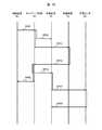
図5に、第1の実施の形態によるログ解析システムの試運転時の実施処理の流れを示すシーケンス図を示す。 FIG. 5 shows a sequence diagram showing a flow of execution processing at the time of trial run of the log analysis system according to the first embodiment.
監視装置30のモード管理モジュール310は、監視装置30の動作モードを初期モードに設定する。ここで、動作モードが初期モードに設定できない、または、以降の処理が初期モードに設定されないまま実行されようとする場合には、以降の処理を中止しても良い。 The
制御装置101は制御処理モジュール1011で制御コマンドを生成し、通信モジュール1021を介してネットワーク装置20へ制御コマンドを送信する(SP11)。ネットワーク装置20のパケット複製モジュール201は、制御装置101からの制御コマンドを、第1通信モジュール202を介して取得し、通信パケット1200として制御コマンドを複製する。The
第2通信モジュール203は、パケット複製モジュール201が複製した制御コマンドを、監視装置30へ送信する(SP12)。また第3通信モジュール204は、パケット複製モジュール201が複製した制御コマンドを、制御装置10nへ送信する(SP13)。The
監視装置30の通信パケット取得モジュール302は、通信モジュール301を介して制御コマンドを取得すると、受信時刻および受信サイズを取得し、通信パケット格納モジュール307へ通信パケット1200を格納する。 When the communication
制御装置10nの制御処理モジュール101nは、通信モジュール102nを介して制御コマンドを取得すると、制御コマンドに基づき処理を行い、制御コマンドに対する応答を、通信モジュール102nを介してネットワーク装置20へ返送する(SP14)。
ネットワーク装置20のパケット複製モジュール201は、制御装置10nからの制御コマンドに対する応答を、第3通信モジュール204を介して取得すると、制御コマンドに対する応答を複製する。When the
複製した制御コマンドに対する応答を、第2通信モジュール203を介して監視装置30へ送信する(SP15)。また複製した制御コマンドに対する応答を、第1通信モジュール202を介して制御装置101へ送信する(SP16)。The response to the duplicated control command is transmitted to the
監視装置30の通信パケット取得モジュール302は、通信モジュール301を介して制御コマンドに対する応答を取得すると、受信時刻および受信サイズを取得し、通信パケット格納モジュール307へ通信パケット1200を格納する。 When the communication
監視装置30の通信パケット取得モジュール302は、例えば、監視装置30が外部から電気的な信号をスイッチなどから受けること、通信によって制御コマンドなどで指示を与えられること、または、予め送受信される通信パケット数が定まっていて、その通信パケット数が流れたことによって、試運転が終了したか否かを判断する。 In the communication
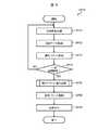
図6に監視装置30におけるパターン格納処理の処理手順を示すフローチャートを示す。通信パケット取得モジュール302は、通信モジュール301を介して制御コマンドや制御コマンドに対する応答を取得すると、受信時刻および受信サイズを取得し(SP21およびSP22)、通信パケット格納モジュール307へ通信パケット1200を格納する(SP23)。 FIG. 6 shows a flowchart showing a processing procedure of the pattern storage process in the
通信パケット格納モジュール307へ通信パケット1200を格納すると、通信パケット取得モジュール302は、試運転が終了したか否かを判断する(SP24)。通信パケット取得モジュール302は、この判断で否定結果を得るとステップSP21へ戻り、ステップSP24で肯定結果を得るまでステップSP21〜ステップSP23の処理を繰り返す。この繰り返し処理により、監視装置30はログ解析システムの試運転時における通信パケット1200を取得する。 When the
通信パケット取得モジュール302が、試運転が終了したことによってステップSP24で肯定結果を得ると、パターン抽出モジュール303は図7に示す定常パターンを抽出するパターン抽出処理を行う(SP25)。 When the communication
パターン抽出モジュール303は、通信パケット格納モジュール307から通信パケット1200を取得する(SP251)。この際にパターン抽出モジュール303が取得する通信パケット1200は、通信パケット格納モジュール307に格納されている全ての通信パケット1200でも良いし、あらかじめ定められたデータ量に該当する通信パケット1200でも良い。 The pattern extraction module 303 acquires the
パターン抽出モジュール303は、取得した通信パケット1200の送受信時刻とサイズが記載した、時系列に沿ったデータを生成する(SP252)。なお送受信時刻とともに記載する情報はサイズに限ったものではなく、当該時刻における通信パケット1200の送受信回数や特定のデータサイズに該当する通信パケット1200の量などでも良い。 The pattern extraction module 303 generates data in chronological order in which the transmission / reception time and size of the acquired
パターン抽出モジュール303は、生成した時系列データを周波数変換し、周波数とその強度(影響度)分布の情報を生成する(SP253)。なお周波数変換には例えばFFT(高速フーリエ変換)などの手法が利用可能である。 The pattern extraction module 303 frequency-converts the generated time-series data to generate information on the frequency and its intensity (influence) distribution (SP253). For frequency conversion, for example, a method such as FFT (Fast Fourier Transform) can be used.
パターン抽出モジュール303は、周波数変換したデータに含まれる周波数とその強度(影響度)を定常パターンとして定常パターン格納モジュール308に格納する(SP26)。モード管理モジュール310は、監視装置30の動作モードを運用モードに設定し(SP27)、監視装置30は通信パターン格納処理を終了する。なお、動作モードを設定する際に通信パケット格納モジュール307に格納した通信パケット1200を削除してもよい。 The pattern extraction module 303 stores the frequency included in the frequency-converted data and its intensity (influence) as a steady pattern in the steady pattern storage module 308 (SP26). The
第1の実施の形態によるログ解析システムの運用時の実施処理の流れは、図5に示すシーケンス図と概要は同じであるため、差異がある箇所についてのみ説明する。 Since the flow of the execution process during the operation of the log analysis system according to the first embodiment is the same as the sequence diagram shown in FIG. 5, only the differences will be described.
運用時には、モード管理モジュール310は設定を変更しない。また監視装置30はパターン格納処理の代わりに、図8に示す異常パケット格納処理を行う。通信パケット取得モジュール302は、通信モジュール301を介して制御コマンドや制御コマンドに対する応答を取得すると、受信時刻および受信サイズを取得し(SP31およびSP32)、通信パケット格納モジュール307へ通信パケット1200を格納する(SP33)。 During operation, the
通信パケット格納モジュール307へ通信パケット1200を格納すると、通信パケット取得モジュール302は、運用状態に設定されてから一定時間が経過したか否かを判断する(SP34)。なおステップSP34の判断の条件は一定時間の経過ではなくてもよく、例えば監視装置30が外部から電気的な信号をスイッチなどから受けたか否か、通信によって制御コマンドなどで指示を与えられたか否か、または、予め送受信される通信パケット数が定まっていて、その通信パケット数が流れたか否か、によって判断してもよい。 When the
通信パケット取得モジュール302は、この判断で否定結果を得るとステップSP31へ戻り、ステップSP34で肯定結果を得るまでステップSP31〜ステップSP33の処理を繰り返す。この繰り返し処理により、監視装置30は運用時のログ解析システムにおける通信パケット1200を取得する。 When the communication
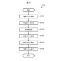
通信パケット取得モジュール302が、一定時間が経過したことによってステップSP34で肯定結果を得ると、異常パターン抽出モジュール304は図9に示す異常パケットを抽出する異常パケット抽出処理を行う(SP35)。 When the communication
異常パターン抽出モジュール304は、通信パケット格納モジュール307から通信パケット1200を取得する(SP351)。この際にパターン抽出モジュール303が取得する通信パケット1200は、通信パケット格納モジュール307に格納されている全ての通信パケット1200でも良いし、あらかじめ定められた期間に該当する通信パケット1200でも良いし、あらかじめ定められたデータ量に該当する通信パケット1200でも良い。 The abnormality pattern extraction module 304 acquires the
異常パターン抽出モジュール304は、取得した通信パケット1200の送受信時刻とサイズが記載した、時系列に沿ったデータを生成する(SP352)。なお送受信時刻とともに記載する情報はサイズに限ったものではなく、当該時刻における通信パケット1200の送受信回数や特定のデータサイズに該当する通信パケット1200の量などでも良い。 The anomaly pattern extraction module 304 generates data in chronological order in which the transmission / reception time and size of the acquired
異常パターン抽出モジュール304は、生成した時系列データを周波数変換し、周波数とその強度(影響度)分布の情報を生成する(SP353)。なお周波数変換には例えばFFT(高速フーリエ変換)などの手法が利用可能である。 The anomaly pattern extraction module 304 frequency-converts the generated time-series data to generate information on the frequency and its intensity (influence) distribution (SP353). For frequency conversion, for example, a method such as FFT (Fast Fourier Transform) can be used.
異常パターン抽出モジュール304は、定常パターン格納モジュール308に格納されている定常パターンを取得する(SP354)。異常パターン抽出モジュール304は、周波数変換した時系列データと取得した定常パターンとを比較し差分を抽出することで異常パターンを抽出する(SP355)。 The anomaly pattern extraction module 304 acquires the steady-state pattern stored in the steady-state pattern storage module 308 (SP354). The anomaly pattern extraction module 304 extracts an anomaly pattern by comparing the frequency-converted time series data with the acquired steady-state pattern and extracting the difference (SP355).
異常パケット復元モジュール305は、異常パターン抽出モジュール304が抽出した異常パターンを基に異常パケットを復元する(SP356)。実際上、異常パケット復元モジュール305は、異常パターンを逆FFT(逆高速フーリエ変換)などの逆周波数変換することで、時刻およびサイズの情報を取得する。 The abnormal
異常パケット復元モジュール305は、取得した時刻およびサイズの情報と、異常パターン抽出モジュール304が通信パケット格納モジュール307から取得した通信パケット1200とを用いて異常パケットを復元する。 The abnormal
異常パケット復元モジュール305は、復元した異常パケットを異常パケット格納モジュールへ格納する(SP36)。出力モジュール306は、異常パケット復元モジュール305が復元した異常パケットなどをディスプレイなどの画面に出力し(SP37)、監視装置30は異常パケット格納処理を終了する。 The abnormal
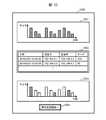
図10に監視画面1000の構成を略線的に示す略線図を示す。監視画面1000は、出力モジュール306が出力する画面であり、通信状況1001、通信データ詳細1002、異常通信抽出結果1003および遷移ボタン1004を備える。 FIG. 10 shows a schematic diagram showing the configuration of the
通信状況1001は、通信パケット1200の日時を横軸に、サイズ情報を縦軸にしたグラフとなっているが、これに限定されない。通信データ詳細1002は、通信パケット1200の日時情報、送受信先、サイズ情報を備えるが、これに限定されない。 The
異常通信抽出結果1003は、通信パケット1200のうち異常パケットと想定されるパケットの日時情報とサイズ情報が含まれるが、これに限定されるものではない。遷移ボタン1004が押下されることにより、図11に示す異常監視画面1100へと画面表示が遷移する。 The abnormal
なお、監視画面1000の構成要素は上記に限定されるものではなく、少なくとも上記の要素が含まれていればよい。また、監視画面1000の構成要素の順序は上記に限定されるものではない。 The components of the
異常監視画面1100は、出力モジュール306が出力する画面であり、異常パケット概要1101、異常パケット詳細1102および遷移ボタン1103を備える。異常パケット概要1101は、日時情報を横軸に、単位時間あたりの異常パケット数を縦軸にしたグラフとなっているが、これに限定されるものではなく、例えば縦軸をサイズ情報としてもよい。 The
異常パケット詳細1102は、異常パケットの日時情報、送受信先、実際に送受信されたデータ情報が含まれるが、これに限定されるものではない。なお、異常監視画面1100の構成要素は上記に限定されるものではなく、少なくとも上記の要素が含まれていればよい。また、異常監視画面1100の構成要素の順序は上記に限定されるものではない。 The
なお上記では監視画面1000と異常監視画面1100は別の画面表示としたが、監視画面1000の遷移ボタン1004の代わりに、異常パケット概要1101、異常パケット詳細1102を表示してもよいものとする。 In the above, the
図12に通信パケット1200の構成を示す概念図を示す。通信パケット1200は通信パケット格納モジュール307に格納され、複数であり、パケットを受信した受信日時1201、パケットのサイズ1202およびパケットのバイナリデータであるパケットデータ1203を備える。 FIG. 12 shows a conceptual diagram showing the configuration of the
通信パケット1200の構成要素は上記に限定されるものではなく、少なくとも上記の要素が含まれていればよい。また、通信パケット1200の構成要素の順序は上記に限定されるものではない。 The components of the
図13に通信パターン1300の構成を示す概念図を示す。通信パターン1300は、監視装置30の定常パターン格納モジュール308に格納されている定常パターンや異常パターン抽出モジュール304によって抽出される異常パターンなどである。 FIG. 13 shows a conceptual diagram showing the configuration of the
通信パターン1300は、通信の発生する周期1301とその周期1301を構成するデータの占める割合を示す強度である影響度1302から構成される。ここで、通信パターン1300の構成要素は上記に限定されるものではなく、少なくとも上記の要素が含まれていればよい。また、通信パターン1300の構成要素の順序は上記に限定されるものではない。 The
図14に通信パターン1300の周波数と強度の分布を示す概念図を示す。分布グラフ1401は通信パターン1300を、縦軸を強度とし、横軸を周波数(Hz)としたグラフである。分布グラフ1402は定常パターンをグラフ化しており、分布グラフ1403は異常パターンをグラフ化している。 FIG. 14 shows a conceptual diagram showing the frequency and intensity distribution of the
ここでは、通信パターン1300として、1Hz(影響度が15)、5Hz(影響度が10)、10Hz(影響度が5)および15Hz(影響度が10)を取得したとし、定常パターンが1Hz(影響度が15)、5Hz(影響度が10)および15Hz(影響度が10)の場合、10Hz(影響度が5)を異常パターンとして抽出している。 Here, it is assumed that 1 Hz (15 influence), 5 Hz (10 influence), 10 Hz (5 influence) and 15 Hz (10 influence) are acquired as the
(1−3)本実施の形態の効果
以上のように本実施の形態のログ解析システムでは、監視装置において、制御システムの試運転時などに収集した定常的な動作パターンに関連するログを除外したログデータを出力することにより、異常検知や対処に必要となる情報を効果的に抽出するようにした。(1-3) Effect of the present embodiment As described above, in the log analysis system of the present embodiment, the logs related to the steady operation pattern collected during the trial run of the control system are excluded in the monitoring device. By outputting log data, information necessary for abnormality detection and countermeasures can be effectively extracted.
従って、本ログ解析システムでは、不正アクセスから制御システムをより効果的に防衛することできるログ解析システムおよびその方法を実現できる。 Therefore, in this log analysis system, it is possible to realize a log analysis system and a method thereof that can more effectively protect the control system from unauthorized access.
(2)第2の実施の形態
第1の実施の形態では、企業内ネットワークなどの安全性の高いネットワーク40のみで接続されたログ解析システムについて説明したが、図15に示すインターネットなどの外部ネットワーク70を通して、制御システムの外のネットワークでログ解析を行ってもよい。第1の実施の形態との差分について説明する。(2) Second Embodiment In the first embodiment, a log analysis system connected only by a highly
制御装置10、ネットワーク装置20およびネットワーク40に関しては第1の実施の形態と同様であるため、説明を省略する。本実施の形態では、監視装置30に相当する装置は、収集装置50および監視センタ60である。収集装置50および監視センタ60のハードウェア構成は監視装置30と同様であるため、説明を省略する。 Since the
収集装置50は、収集装置501〜50nの複数個あり、レイヤ2スイッチやサーバなどの通信パケット1200を収集する装置であり、通信モジュール501、通信パケット取得モジュール502、パターン抽出モジュール503、異常パターン抽出モジュール504、異常パケット復元モジュール505、外部通信モジュール506、通信パケット格納モジュール507、定常パターン格納モジュール508およびモード管理モジュール509を備える。The
通信モジュール501、通信パケット取得モジュール502、パターン抽出モジュール503、異常パターン抽出モジュール504および異常パケット復元モジュール505は通信モジュール301、通信パケット取得モジュール302、パターン抽出モジュール303、異常パターン抽出モジュール304および異常パケット復元モジュール305と同等であるため、説明を省略する。
通信パケット格納モジュール507、定常パターン格納モジュール508およびモード管理モジュール509は通信パケット格納モジュール307、定常パターン格納モジュール308およびモード管理モジュール310と同等であるため、説明を省略する。外部通信モジュール506は外部ネットワーク70を介して他の収集装置50の外部通信モジュール506および監視センタと通信を行う。 Since the communication
なおそれぞれの収集装置50が通信モジュール501n、通信パケット取得モジュール502n、パターン抽出モジュール503n、異常パターン抽出モジュール504n、異常パケット復元モジュール505n、外部通信モジュール506n、通信パケット格納モジュール507n、定常パターン格納モジュール508nおよびモード管理モジュール509nといった各モジュールを備える。通信モジュール501nは例えばネットワーク装置20の第4通信モジュールと通信する。Each
監視センタ60は、出力モジュール601、集約異常パケット格納モジュール602および通信モジュール603を備える。通信モジュール603は外部ネットワーク70を介して、収集装置50から異常パケットを取得する。集約異常パケット格納モジュール602は、それぞれの収集装置50から取得した異常パケットを格納する。出力モジュール601は、それぞれの収集装置50から取得した異常パケットを出力する。 The
出力モジュール601がディスプレイなどに出力する出力画面については第1の実施の形態で説明した通りであるが、複数の収集装置の結果を示すため、収集装置毎に監視画面があってもよいし、収集装置の識別情報を付加して表示してもよい。 The output screen output by the
本実施の形態によるログ解析システムの試運転時の実施処理の流れは、図5に示すシーケンス図の流れと同じであるため、説明を省略する。なお、監視装置30のモード管理モジュール310の代わりに、収集装置50のモード管理モジュール509が動作モードを初期モードに設定する。 Since the flow of the execution process at the time of the trial run of the log analysis system according to the present embodiment is the same as the flow of the sequence diagram shown in FIG. 5, the description thereof will be omitted. Instead of the
第2の実施の形態によるログ解析システムの運用時の実施処理の流れは、第2の実施の形態によるログ解析システムの運用時の実施処理の流れと概要は同じであるため、差異がある箇所についてのみ図16を用いて説明する。 Since the flow of the execution process during the operation of the log analysis system according to the second embodiment is the same as the flow of the execution process during the operation of the log analysis system according to the second embodiment, there are differences. Only will be described with reference to FIG.
ステップSP41〜ステップSP46は、監視装置30を収集装置50に置き換えるとステップSP11〜ステップSP16と同様である。収集装置50の外部通信モジュール506は異常パケット復元モジュール505が復元した異常パケットを監視センタ60へ送信する(SP47)。 Steps SP41 to SP46 are the same as steps SP11 to SP16 when the
本実施の形態においては、処理を収集装置50および監視センタ60で分けるため処理負荷が分散し高速な処理が実現できる。 In the present embodiment, since the processing is divided by the
(3)第3の実施の形態
第2の実施の形態では、収集装置50から異常パケットを監視センタ60へ送信したが、本実施の形態においては、図17に示すように、収集装置50は通信パケット1200を監視センタ60へ送信し、監視センタ60で異常パターンの抽出および異常パケットの復元を行う。(3) Third Embodiment In the second embodiment, the abnormal packet is transmitted from the collecting
制御装置10、ネットワーク装置20およびネットワーク40に関しては第1の実施の形態と同様であるため、説明を省略する。収集装置50および監視センタ60のハードウェア構成は第2の実施の形態と同様であるため、説明を省略する。 Since the
収集装置50は、収集装置501〜50nであり、レイヤ2スイッチやサーバなどの通信パケット1200を収集する装置であり、通信モジュール501、通信パケット取得モジュール502、外部通信モジュール506、通信パケット格納モジュール507、およびモード管理モジュール509を備える。The
通信モジュール501、通信パケット取得モジュール502、外部通信モジュール506、通信パケット格納モジュール507およびモード管理モジュール509は第2の実施の形態と同等であるため、説明を省略する。 Since the
監視センタ60は、レイヤ2スイッチやサーバなどのログ解析システムを監視する装置であり、出力モジュール601、集約異常パケット格納モジュール602、通信モジュール603、パターン抽出モジュール604、異常パターン抽出モジュール605、異常パケット復元モジュール606、および定常パターン格納モジュール607を備える。 The
ログ解析システムの試運転時には、パターン抽出モジュール604は、通信モジュール603および外部ネットワーク70を介して、収集装置50から通信パケット1200を取得する。運用時には、異常パターン抽出モジュール605は、通信モジュール603および外部ネットワーク70を介して、収集装置50から通信パケット1200を取得する。 During the trial run of the log analysis system, the
出力モジュール601がディスプレイなどに出力する出力画面については第2の実施の形態で説明した通りである。 The output screen output by the
本実施の形態によるログ解析システムの試運転時の実施処理の流れは、図16に示すシーケンス図の流れと概要は同じであるため、差異がある箇所についてのみ図18を用いて説明する。 Since the flow of the execution process at the time of trial run of the log analysis system according to the present embodiment is the same as the flow of the sequence diagram shown in FIG. 16, only the differences will be described with reference to FIG.
最初に収集装置50のモード管理モジュール509は、収集装置50の動作モードを初期モードに設定する。ここで、動作モードが初期モードに設定できない、または、以降の処理が初期モードに設定されないまま実行されようとする場合には、以降の処理を中止しても良い。 First, the
次に監視センタ60のモード管理モジュール608は、監視センタ60の動作モードを初期モードに設定する。ここで、動作モードが初期モードに設定できない、または、以降の処理が初期モードに設定されないまま実行されようとする場合には、以降の処理を中止しても良い。 Next, the
ステップSP51〜ステップSP57はステップSP41〜ステップSP47と同様である。収集装置50の外部通信モジュール506から通信パケット1200が監視センタ60の通信モジュール603に送信される(SP57)。 Steps SP51 to SP57 are the same as steps SP41 to SP47.
監視センタ60の通信モジュール603が通信パケット1200を受信すると、監視センタは各処理を行ったのち、モード管理モジュール608は、監視センタ60の動作モードを運用モードに設定し、監視センタ60の通信モジュール603は収集装置50の外部通信モジュール506へ応答を返送する(SP58)。 When the
収集装置50の外部通信モジュール506が応答を受信すると、モード管理モジュール509は収集装置50の動作モードを運用モードに設定する。 When the
本実施の形態によるログ解析システムの運用時の実施処理の流れは、第2の実施の形態によるログ解析システムの運用時の実施処理の流れと同じであるため、説明を省略する。 Since the flow of the execution process during the operation of the log analysis system according to the present embodiment is the same as the flow of the execution process during the operation of the log analysis system according to the second embodiment, the description thereof will be omitted.
本実施の形態においては、処理を収集装置50および監視センタ60で分けるため処理が分散し高速な処理が実現できる。 In the present embodiment, since the processing is divided by the
(4)その他の実施の形態
なお上述の第1、第2および第3の実施の形態においては、監視装置30、収集装置50およびネットワーク装置20が別装置である場合について述べたが、本発明はこれに限らず、例えば監視装置30や収集装置50内にネットワーク装置20の機能が含まれている場合や、制御装置10や監視装置30や収集装置50にネットワーク40との通信機能が含まれておらず、別の装置を経由してネットワーク40と通信を行うようにしてもよい。(4) Other Embodiments In the first, second, and third embodiments described above, the case where the
また上述の第1、第2および第3の実施の形態においては、ネットワーク40や外部ネットワーク70にフィルタをかけていない場合について述べたが、本発明はこれに限らず、ネットワーク40や外部ネットワーク70にフィルタをかけてもよい。 Further, in the first, second and third embodiments described above, the case where the
10:制御装置、11:通信装置、12:入出力装置、13:記憶装置、14:CPU、15:メモリ、16:内部通信線、101:制御処理モジュール、102:通信モジュール、20:ネットワーク装置、21:通信装置、211:第1通信装置、212:第2通信装置、213:第3通信装置、22:記憶装置、23:入出力装置、24:CPU、25:メモリ、26:内部通信線、201:パケット複製モジュール、202:第1通信モジュール、203:第2通信モジュール、204:第3通信モジュール、30:監視装置、31:通信装置、32:入出力装置、33:記憶装置、34:CPU、35:メモリ、36:読取装置、37:記憶媒体、38:内部通信線、301:通信モジュール、302:通信パケット取得モジュール、303:パターン抽出モジュール、304:異常パターン抽出モジュール、305:異常パケット復元モジュール、306:出力モジュール、307:通信パケット格納モジュール、308:定常パターン格納モジュール、309:異常パケット格納モジュール、310:モード管理モジュール、50:収集装置、501:通信モジュール、502:通信パケット取得モジュール、503:パターン抽出モジュール、504:異常パターン抽出モジュール、505:異常パケット復元モジュール、506:外部通信モジュール、507:通信パケット格納モジュール、508:定常パターン格納モジュール、509:モード管理モジュール、60:監視センタ、601:出力モジュール、602、集約異常パケット格納モジュール、603:通信モジュール、604:パターン抽出モジュール、605:異常パターン抽出モジュール、606:異常パケット復元モジュール、607:定常パターン格納モジュール、608:モード管理モジュール、70:外部ネットワーク。10: Control device, 11: Communication device, 12: Input / output device, 13: Storage device, 14: CPU, 15: Memory, 16: Internal communication line, 101: Control processing module, 102: Communication module, 20: Network device , 21: communication device,211: first communication device, 212: second communication device, 213: third communication device, 22: storage device, 23: input device, 24: CPU, 25: memory, 26 : Internal communication line, 201: Packet replication module, 202: First communication module, 203: Second communication module, 204: Third communication module, 30: Monitoring device, 31: Communication device, 32: Input / output device, 33: Storage device, 34: CPU, 35: Memory, 36: Reader, 37: Storage medium, 38: Internal communication line, 301: Communication module, 302: Communication packet acquisition module, 303: Pattern extraction module, 304: Abnormal pattern extraction Module, 305: Abnormal packet recovery module, 306: Output module, 307: Communication packet storage module, 308: Steady pattern storage module, 309: Abnormal packet storage module, 310: Mode management module, 50: Collector, 501: Communication module , 502: Communication packet acquisition module, 503: Pattern extraction module, 504: Abnormal pattern extraction module, 505: Abnormal packet recovery module, 506: External communication module, 507: Communication packet storage module, 508: Steady pattern storage module, 509: Mode management module, 60: Monitoring center, 601: Output module, 602, Aggregation abnormal packet storage module, 603: Communication module, 604: Pattern extraction module, 605: Abnormal pattern extraction module, 606: Abnormal packet recovery module, 607: Steady Pattern storage module, 608: mode management module, 70: external network.
Claims (9)
Translated fromJapanese前記複数の通信ログに対応する一定時間における複数の通信パケットをネットワークから受信するネットワーク装置と、
前記ネットワーク装置への通信を監視する監視装置と、
を備え、
前記監視装置は、前記一定時間における複数の通信パケットの送受信時刻を含むデータの時系列データを周波数変換することにより得られた通信パターンと不正アクセスのない状態の通信におけるパターンである定常パターンとの差分としてのパターンである異常パターンを求め、前記異常パターンに対して逆周波数変換を施すことで取得された情報であり時刻を含む情報に基づいて、前記異常パターンに該当する通信パケットである異常パケットを復元し、復元された前記異常パケットを報知する
ログ解析システム。A log analysis system that analyzesmultiple communication logs ofa control device.
A network device that receives aplurality of communication packets from the network at afixed time corresponding to theplurality of communication logs, and
A monitoring device that monitors communication to the network device, and
With
The monitoring device hasa communication patternobtained by frequency-converting time-series data of data including transmission / reception timesof a plurality of communication packetsin the fixed time , and a stationary pattern which is a pattern in communication in a state without unauthorized access.Anomalous packet that is a communication packet corresponding to the anomaly pattern based oninformation including time, which is information acquired by obtainingan anomaly pattern which is a pattern as a differenceand performingreverse frequency conversion on theanomaly pattern. A log analysis system that restores the data and notifies the restoredabnormal packet.
請求項1記載のログ解析システム。The log analysis system according to claim 1, wherein the network device duplicates aplurality of communication packetsin the fixed time period and transmits theplurality of communication packets to the monitoring device.
請求項1に記載のログ解析システム。The log analysis system according to claim 1, wherein the monitoring device extracts the communication pattern from the plurality of communication packets based on fluctuations in the transmission / reception cycle and transmission / reception size of eachof the plurality of communication packetsin the fixed time .
前記監視装置は、前記収集装置によって収集された前記一定時間における複数の通信パケットに基づいて前記一定時間における複数の通信パケットを復元する
請求項1に記載のログ解析システム。The collecting device collects aplurality of communication packetsin the fixed time from the network device, and collects aplurality of communication packets.
The log analysis system according to claim 1, wherein the monitoring device restores aplurality of communication packetsin the fixed time based on theplurality of communication packetsin the fixed time collected by the collecting device.
複数の前記収集装置のそれぞれで収集された前記一定時間における複数の通信パケットに基づいて前記一定時間における複数の通信パケットを復元する
請求項4に記載のログ解析システム。The monitoring device
The log analysis system according to claim 4, whereina plurality of communication packetsin the fixed time are restored based on aplurality of communication packetsin the fixed time collected by each of the plurality of collecting devices.
請求項1に記載のログ解析システム。The monitoring device collects aplurality of communication packets in thefixed time , obtains the difference between the communication patternof the plurality of communication packetsin the fixed time and the steady pattern of the communication, and isconstant based on the difference. log analysis system according to claim 1, comprising a collecting device for restoringthe plurality of communication packet information made a difference among aplurality of communication packetsin time, notifying the restored theplurality of communication packets.
前記一定時間における複数の通信パケットを時系列で表示し、前記定常パターンの前記一定時間における複数の通信パケットと前記差分に基づいた前記一定時間における複数の通信パケットとを識別可能な形で表示する
請求項1に記載のログ解析システム。The monitoring device
A plurality of communication packetsin the fixed time are displayed in chronological order, and aplurality of communication packetsin the fixed time of the steady pattern and aplurality of communication packets in thefixed time based on the difference are displayed in an identifiable form. The log analysis system according to claim 1.
前記運転状態は、前記監視装置が前記通信の前記定常パターンを取得するための試運転状態と、試運転状態以外の運用状態であり、
前記監視装置は、前記設定により実行可能な処理が制限される
請求項1に記載のログ解析システム。The monitoring device is set according to the operating state of the control device.
The operating state is a test run state for the monitoring device to acquire the steady pattern of the communication, and an operation state other than the test run state.
The log analysis system according to claim 1, wherein the monitoring device is limited in the processing that can be executed by the setting.
前記ログ解析システムは、
前記複数の通信ログに対応する一定時間における複数の通信パケットをネットワークから受信するネットワーク装置と、
前記ネットワーク装置への通信を監視する監視装置と、
を備え、
前記監視装置が、前記一定時間における複数の通信パケットの送受信時刻を含むデータの時系列データを周波数変換することにより得られた通信パターンと不正アクセスのない状態の通信におけるパターンである定常パターンとの差分としてのパターンである異常パターンを求める第1のステップと、
前記監視装置が、前記異常パターンに対して逆周波数変換を施すことで取得された情報であり時刻を含む情報に基づいて、前記異常パターンに該当する通信パケットである異常パケットを復元する第2のステップと、
前記監視装置が、復元された前記異常パケットを報知する第3のステップと、
を備えるログ解析方法。
It is a log analysis method in a log analysis system that analyzesmultiple communication logs of the control device.
The log analysis system
A network device that receives aplurality of communication packets from the network at afixed time corresponding to theplurality of communication logs, and
A monitoring device that monitors communication to the network device, and
With
A communication patternobtained by frequency-converting time-series data of data including transmission / reception timesof a plurality of communication packetsin the fixed time by the monitoring device and a steady pattern which is a pattern in communication without unauthorized access. The first step of findingan abnormal pattern ,which is a pattern as a difference,
A second second, in which the monitoring device restores anabnormal packet ,which is a communication packet corresponding to the abnormal pattern, based oninformation including time, which is information acquired by performingreverse frequency conversion on theabnormal pattern . Steps and
The third step in which the monitoring device notifies the restoredabnormal packet, and
A log analysis method that includes.
Priority Applications (4)
| Application Number | Priority Date | Filing Date | Title |
|---|---|---|---|
| JP2016214265AJP6793524B2 (en) | 2016-11-01 | 2016-11-01 | Log analysis system and its method |
| US15/795,429US10523696B2 (en) | 2016-11-01 | 2017-10-27 | Log analyzing system and method |
| GB1717787.4AGB2558380B (en) | 2016-11-01 | 2017-10-30 | Log analyzing system and method |
| DE102017219455.3ADE102017219455A1 (en) | 2016-11-01 | 2017-10-30 | Log analysis system and method |
Applications Claiming Priority (1)
| Application Number | Priority Date | Filing Date | Title |
|---|---|---|---|
| JP2016214265AJP6793524B2 (en) | 2016-11-01 | 2016-11-01 | Log analysis system and its method |
Publications (2)
| Publication Number | Publication Date |
|---|---|
| JP2018074465A JP2018074465A (en) | 2018-05-10 |
| JP6793524B2true JP6793524B2 (en) | 2020-12-02 |
Family
ID=60580144
Family Applications (1)
| Application Number | Title | Priority Date | Filing Date |
|---|---|---|---|
| JP2016214265AExpired - Fee RelatedJP6793524B2 (en) | 2016-11-01 | 2016-11-01 | Log analysis system and its method |
Country Status (4)
| Country | Link |
|---|---|
| US (1) | US10523696B2 (en) |
| JP (1) | JP6793524B2 (en) |
| DE (1) | DE102017219455A1 (en) |
| GB (1) | GB2558380B (en) |
Families Citing this family (4)
| Publication number | Priority date | Publication date | Assignee | Title |
|---|---|---|---|---|
| JP6674036B2 (en)* | 2016-10-03 | 2020-04-01 | 日本電信電話株式会社 | Classification device, classification method and classification program |
| US10567264B2 (en)* | 2017-04-06 | 2020-02-18 | Rohde & Schwarz Gmbh & Co. Kg | Protocol test device and method for operating a protocol test device |
| JP2019165301A (en)* | 2018-03-19 | 2019-09-26 | 富士通株式会社 | Program, device and method for packet detection |
| JP7533058B2 (en)* | 2020-09-17 | 2024-08-14 | 富士フイルムビジネスイノベーション株式会社 | Information processing device and information processing program |
Family Cites Families (40)
| Publication number | Priority date | Publication date | Assignee | Title |
|---|---|---|---|---|
| JP2000148276A (en)* | 1998-11-05 | 2000-05-26 | Fujitsu Ltd | Security monitoring device, security monitoring method, and security monitoring program recording medium |
| US9444785B2 (en)* | 2000-06-23 | 2016-09-13 | Cloudshield Technologies, Inc. | Transparent provisioning of network access to an application |
| US6813244B1 (en)* | 2000-11-20 | 2004-11-02 | Fujitsu Limited | Available bandwidth measurement with variable speed probing and zoom-in/zoom-out technique |
| US7283461B2 (en)* | 2002-08-21 | 2007-10-16 | Alcatel Canada Inc. | Detection of denial-of-service attacks using frequency domain analysis |
| JP2005223870A (en)* | 2004-02-05 | 2005-08-18 | Fujio Morita | Method and system for finding illegal communication from log of communication packet |
| EP1714428A4 (en)* | 2004-02-06 | 2009-07-08 | Apparent Networks Inc | METHOD AND APPARATUS FOR CHARACTERIZING A END-TO-END PATH OF A PACKET SWITCHING NETWORK |
| GB0402739D0 (en)* | 2004-02-09 | 2004-03-10 | Saviso Group Ltd | Methods and apparatus for routing in a network |
| US7904956B2 (en)* | 2004-10-01 | 2011-03-08 | Microsoft Corporation | Access authorization with anomaly detection |
| KR100609710B1 (en)* | 2004-11-25 | 2006-08-08 | 한국전자통신연구원 | Network simulation device and method for abnormal traffic analysis |
| KR100639969B1 (en)* | 2004-12-02 | 2006-11-01 | 한국전자통신연구원 | Abnormal traffic control device and its control method |
| US7684390B2 (en)* | 2004-12-30 | 2010-03-23 | Intel Corporation | Integrated circuit capable of transmitting probe packets across a stack of switches |
| JP4594869B2 (en)* | 2006-01-24 | 2010-12-08 | 富士通株式会社 | Condition monitoring device |
| JP4558668B2 (en)* | 2006-03-06 | 2010-10-06 | 株式会社Kddi研究所 | Log analysis device, log analysis program, and recording medium |
| WO2008052291A2 (en)* | 2006-11-03 | 2008-05-08 | Intelliguard I.T. Pty Ltd | System and process for detecting anomalous network traffic |
| JP4667437B2 (en)* | 2007-10-02 | 2011-04-13 | 日本電信電話株式会社 | Abnormal traffic detection apparatus, abnormal traffic detection method, and abnormal traffic detection program |
| JP2009171431A (en)* | 2008-01-18 | 2009-07-30 | Oki Electric Ind Co Ltd | Traffic analyzer, traffic analyzing method, and traffic analyzing system |
| US8059547B2 (en)* | 2008-12-08 | 2011-11-15 | Advantest Corporation | Test apparatus and test method |
| US8085681B2 (en)* | 2008-10-21 | 2011-12-27 | At&T Intellectual Property I, Lp | Centralized analysis and management of network packets |
| JP2010165242A (en)* | 2009-01-16 | 2010-07-29 | Hitachi Cable Ltd | Method and system for detecting abnormality of mobile body |
| JP2010283668A (en)* | 2009-06-05 | 2010-12-16 | Nippon Telegr & Teleph Corp <Ntt> | Traffic classification system and method and program, and abnormal traffic detection system and method |
| US8613085B2 (en)* | 2009-07-22 | 2013-12-17 | Broadcom Corporation | Method and system for traffic management via virtual machine migration |
| JP5488379B2 (en)* | 2010-09-29 | 2014-05-14 | 富士通株式会社 | Mail monitoring system, mail monitoring program, mail monitoring apparatus and mail monitoring method |
| US8151341B1 (en)* | 2011-05-23 | 2012-04-03 | Kaspersky Lab Zao | System and method for reducing false positives during detection of network attacks |
| KR101640476B1 (en)* | 2011-09-16 | 2016-07-25 | 한국전자통신연구원 | Test analysis system of network and analysis method thereof |
| JP5792654B2 (en)* | 2012-02-15 | 2015-10-14 | 株式会社日立製作所 | Security monitoring system and security monitoring method |
| US8891392B2 (en)* | 2012-06-21 | 2014-11-18 | Breakingpoint Systems, Inc. | Dynamic latency analysis system |
| US9203723B2 (en)* | 2013-01-30 | 2015-12-01 | Broadcom Corporation | Network tracing for data centers |
| JP5913145B2 (en) | 2013-02-04 | 2016-04-27 | 日本電信電話株式会社 | Log visualization device, method, and program |
| US20150038164A1 (en)* | 2013-08-01 | 2015-02-05 | Deutsche Telekom Ag | System for analyzing mobile telephone users locations and classifications, while maintaining users privacy constraints |
| US20160212021A1 (en)* | 2013-09-18 | 2016-07-21 | Jolata, Inc. | Highly probable identification of related messages using sparse hash function sets |
| US9432295B2 (en)* | 2013-09-27 | 2016-08-30 | Telefonaktiebolaget Lm Ericsson (Publ) | Systems and methods for high throughput traffic pattern generation |
| WO2015051185A1 (en)* | 2013-10-04 | 2015-04-09 | Cyberflow Analytics, Inc. | Network intrusion detection |
| US9806960B2 (en)* | 2013-11-25 | 2017-10-31 | Google Inc. | Method and system for adjusting heavy traffic loads between personal electronic devices and external services |
| CN105917618B (en)* | 2014-03-18 | 2019-04-19 | 株式会社日立制作所 | Data transfer monitoring system, data transfer monitoring method, and base system |
| JP5640167B1 (en)* | 2014-03-31 | 2014-12-10 | 株式会社ラック | Log analysis system |
| KR20160002058A (en) | 2014-06-30 | 2016-01-07 | 한국전자통신연구원 | Modbus Communication Pattern Learning Based Abnormal Traffic Detection Apparatus and Method |
| US10291506B2 (en)* | 2015-03-04 | 2019-05-14 | Fisher-Rosemount Systems, Inc. | Anomaly detection in industrial communications networks |
| KR102112587B1 (en)* | 2015-03-20 | 2020-05-19 | 한국전자통신연구원 | Packet monitoring device and packet monitoring method for communication packet |
| US10122740B1 (en)* | 2015-05-05 | 2018-11-06 | F5 Networks, Inc. | Methods for establishing anomaly detection configurations and identifying anomalous network traffic and devices thereof |
| US9699205B2 (en)* | 2015-08-31 | 2017-07-04 | Splunk Inc. | Network security system |
- 2016
- 2016-11-01JPJP2016214265Apatent/JP6793524B2/ennot_activeExpired - Fee Related
- 2017
- 2017-10-27USUS15/795,429patent/US10523696B2/ennot_activeExpired - Fee Related
- 2017-10-30DEDE102017219455.3Apatent/DE102017219455A1/enactivePending
- 2017-10-30GBGB1717787.4Apatent/GB2558380B/ennot_activeExpired - Fee Related
Also Published As
| Publication number | Publication date |
|---|---|
| GB201717787D0 (en) | 2017-12-13 |
| GB2558380A (en) | 2018-07-11 |
| GB2558380B (en) | 2021-01-13 |
| JP2018074465A (en) | 2018-05-10 |
| US10523696B2 (en) | 2019-12-31 |
| US20180124083A1 (en) | 2018-05-03 |
| DE102017219455A1 (en) | 2018-05-03 |
Similar Documents
| Publication | Publication Date | Title |
|---|---|---|
| JP6827266B2 (en) | Detection program, detection method and detection device | |
| JP6793524B2 (en) | Log analysis system and its method | |
| CN110851320A (en) | Server downtime supervision method, system, terminal and storage medium | |
| US20170344901A1 (en) | Classifying transactions at network accessible storage | |
| JP2012150805A (en) | Systems and methods for detecting fraud associated with systems application processing | |
| CA3172788A1 (en) | Endpoint security using an action prediction model | |
| CN107423090B (en) | Flash player abnormal log management method and system | |
| JP7274162B2 (en) | ABNORMAL OPERATION DETECTION DEVICE, ABNORMAL OPERATION DETECTION METHOD, AND PROGRAM | |
| JP6213676B2 (en) | Analysis device, analysis method, and analysis program | |
| Farrel et al. | Implementation of security information & event management (siem) wazuh with active response and telegram notification for mitigating brute force attacks on the gt-i2ti usakti information system | |
| CN112650557A (en) | Command execution method and device | |
| CN110213055B (en) | Information updating method and device, computer equipment and computer readable storage medium | |
| CN112256532A (en) | Test interface generation method and device, computer equipment and readable storage medium | |
| JP6552136B1 (en) | Exercise display program for cyber attacks | |
| CN117714162A (en) | A micro-sensing and intelligent management and control method and system based on data security | |
| KR101650445B1 (en) | Apparatus and method for detecting webshell in real time using kernel-based file event notification function | |
| WO2023181241A1 (en) | Monitoring server device, system, method, and program | |
| JP6972735B2 (en) | Display control program, display control method and display control device | |
| CN116881741B (en) | Alarm filtering method, device, medium and electronic equipment | |
| Bella et al. | A near-miss management system architecture for the forensic investigation of software failures | |
| CN105446861A (en) | Linux-based IPMI (intelligent platform management interface) interface load stability monitoring method | |
| TWI874252B (en) | Anomaly detection device and anomaly detection method by utilizing data augmentation | |
| CN104537090A (en) | User information standardization data processing method and device | |
| JP6254329B2 (en) | Idle process discovery and constraints | |
| JP2013197601A (en) | Fault detection device, fault detection method, and program |
Legal Events
| Date | Code | Title | Description |
|---|---|---|---|
| A621 | Written request for application examination | Free format text:JAPANESE INTERMEDIATE CODE: A621 Effective date:20190904 | |
| A977 | Report on retrieval | Free format text:JAPANESE INTERMEDIATE CODE: A971007 Effective date:20200713 | |
| A131 | Notification of reasons for refusal | Free format text:JAPANESE INTERMEDIATE CODE: A131 Effective date:20200811 | |
| A521 | Request for written amendment filed | Free format text:JAPANESE INTERMEDIATE CODE: A523 Effective date:20200930 | |
| TRDD | Decision of grant or rejection written | ||
| A01 | Written decision to grant a patent or to grant a registration (utility model) | Free format text:JAPANESE INTERMEDIATE CODE: A01 Effective date:20201104 | |
| A61 | First payment of annual fees (during grant procedure) | Free format text:JAPANESE INTERMEDIATE CODE: A61 Effective date:20201110 | |
| R150 | Certificate of patent or registration of utility model | Ref document number:6793524 Country of ref document:JP Free format text:JAPANESE INTERMEDIATE CODE: R150 | |
| LAPS | Cancellation because of no payment of annual fees |