JP6793024B2 - Surgical instruments for dental implants - Google Patents
Surgical instruments for dental implantsDownload PDFInfo
- Publication number
- JP6793024B2 JP6793024B2JP2016236477AJP2016236477AJP6793024B2JP 6793024 B2JP6793024 B2JP 6793024B2JP 2016236477 AJP2016236477 AJP 2016236477AJP 2016236477 AJP2016236477 AJP 2016236477AJP 6793024 B2JP6793024 B2JP 6793024B2
- Authority
- JP
- Japan
- Prior art keywords
- adapter
- dental
- fixture
- driver
- surgical instrument
- Prior art date
- Legal status (The legal status is an assumption and is not a legal conclusion. Google has not performed a legal analysis and makes no representation as to the accuracy of the status listed.)
- Active
Links
- 239000004053dental implantSubstances0.000titleclaimsdescription44
- 230000005540biological transmissionEffects0.000claimsdescription10
- 210000000214mouthAnatomy0.000claimsdescription4
- 230000002093peripheral effectEffects0.000description18
- 239000007943implantSubstances0.000description4
- 230000004048modificationEffects0.000description4
- 238000012986modificationMethods0.000description4
- 210000000988bone and boneAnatomy0.000description2
- 210000004373mandibleAnatomy0.000description2
- 238000000034methodMethods0.000description2
- 238000001356surgical procedureMethods0.000description2
- 208000002925dental cariesDiseases0.000description1
- 239000002184metalSubstances0.000description1
- 239000011347resinSubstances0.000description1
- 229920005989resinPolymers0.000description1
- 239000007787solidSubstances0.000description1
Images


Classifications
- A—HUMAN NECESSITIES
- A61—MEDICAL OR VETERINARY SCIENCE; HYGIENE
- A61C—DENTISTRY; APPARATUS OR METHODS FOR ORAL OR DENTAL HYGIENE
- A61C8/00—Means to be fixed to the jaw-bone for consolidating natural teeth or for fixing dental prostheses thereon; Dental implants; Implanting tools
- A61C8/0089—Implanting tools or instruments
- A—HUMAN NECESSITIES
- A61—MEDICAL OR VETERINARY SCIENCE; HYGIENE
- A61C—DENTISTRY; APPARATUS OR METHODS FOR ORAL OR DENTAL HYGIENE
- A61C1/00—Dental machines for boring or cutting ; General features of dental machines or apparatus, e.g. hand-piece design
- A61C1/08—Machine parts specially adapted for dentistry
- A61C1/18—Flexible shafts; Clutches or the like; Bearings or lubricating arrangements; Drives or transmissions
- A61C1/185—Drives or transmissions
- A61C1/186—Drives or transmissions with torque adjusting or limiting means
Landscapes
- Health & Medical Sciences (AREA)
- Oral & Maxillofacial Surgery (AREA)
- Orthopedic Medicine & Surgery (AREA)
- Dentistry (AREA)
- Epidemiology (AREA)
- Life Sciences & Earth Sciences (AREA)
- Animal Behavior & Ethology (AREA)
- General Health & Medical Sciences (AREA)
- Public Health (AREA)
- Veterinary Medicine (AREA)
- Dental Prosthetics (AREA)
- Dental Tools And Instruments Or Auxiliary Dental Instruments (AREA)
Description
Translated fromJapanese本発明は、歯科インプラント用手術器具に関する。 The present invention relates to surgical instruments for dental implants.
従来から、体内に埋め込まれるインプラント(特に歯科インプラント)手術が注目されている。歯科インプラントは、一般に、虫歯や破損により永久歯の歯根が失われた場合、歯槽骨に設けた穴にフィクスチャーを挿入して固定するものである。 Traditionally, implant surgery (especially dental implants) that is implanted in the body has attracted attention. Dental implants generally insert and fix a fixture in a hole provided in the alveolar bone when the root of a permanent tooth is lost due to tooth decay or breakage.
歯槽骨に対してフィクスチャーを固定する手術を行う際には、先端をフィクスチャーと嵌合し、ハンドピース等からの回転力を伝達させるインプラント用ドライバー等と呼ばれる手術器具が用いられる(例えば、特許文献1)。 When performing an operation to fix a fixture to the alveolar bone, a surgical instrument called an implant driver or the like is used in which the tip is fitted with the fixture and the rotational force from a handpiece or the like is transmitted (for example). Patent Document 1).
また、歯科インプラント用手術器具として、インプラント用ドライバー(以下、単に歯科ドライバーという)を手動又はトルクレンチなどにより回転させるためのアダプタが公知である。 Further, as a surgical instrument for dental implants, an adapter for rotating an implant driver (hereinafter, simply referred to as a dental driver) manually or by a torque wrench or the like is known.
従来の歯科ドライバーは、回転軸部を有しており、先端側にフィクスチャーと嵌合可能な多角形状の回転伝達軸部が設けられている。また回転軸部のフィクスチャーと反対側は、筒状に形成されたアダプタの中空部内に収納される。回転軸部の略中央位置には横断面が四角形状の連結部が設けられている。 A conventional dental driver has a rotation shaft portion, and a polygonal rotation transmission shaft portion that can be fitted with a fixture is provided on the tip side. The side of the rotating shaft opposite to the fixture is housed in the hollow portion of the adapter formed in a tubular shape. A connecting portion having a quadrangular cross section is provided at a substantially central position of the rotating shaft portion.
アダプタは、フィクスチャーと反対側に、トルクレンチを連結するレンチ連結部を有し、フィクスチャー側に、連結部と対応する形状の把持部を有している。このアダプタの把持部とドライバーの連結部とで把持機構が構成される。 The adapter has a wrench connecting portion for connecting a torque wrench on the opposite side of the fixture, and has a grip portion having a shape corresponding to the connecting portion on the fixture side. A gripping mechanism is composed of a gripping portion of this adapter and a connecting portion of a driver.
この連結機構により、ドライバーとアダプタとが連結され、アダプタのレンチ連結部を手で回す又はトルクレンチが嵌合されて回転力が加えられると、フィクスチャーに回転力を伝達できる。なお、把持部は、連結部との回転方向の固定を強めるために板バネや、スリットなどが具備されている。 By this connecting mechanism, the driver and the adapter are connected, and when the wrench connecting portion of the adapter is turned by hand or the torque wrench is fitted and the rotational force is applied, the rotational force can be transmitted to the fixture. The grip portion is provided with a leaf spring, a slit, or the like in order to strengthen the fixation in the rotational direction with the connecting portion.
従来の歯科ドライバーとアダプタを有する歯科インプラント用手術器具は、以下のような課題点がある。 The conventional surgical instrument for dental implants having a dental screwdriver and an adapter has the following problems.
歯科ドライバーとアダプタを連結する把持機構が形成される位置は、歯科インプラント用手術器具の最もトルクが掛かる位置である。 The position where the gripping mechanism connecting the dental driver and the adapter is formed is the position where the most torque is applied to the surgical instrument for dental implants.
したがって、把持機構に大きなトルク力が度々掛かって、歯科ドライバーの連結部やアダプタの把持部が変形したり破損する虞がある。更に、把持部に連結部との回転方向の固定を強めるために弾性力を有する板バネやスリットなどが形成されると、板バネやスリットが脆弱部となり、耐トルク力を低下させてしまう要因となる。 Therefore, a large torque force is often applied to the gripping mechanism, and there is a risk that the connecting portion of the dental driver and the gripping portion of the adapter will be deformed or damaged. Further, if a leaf spring or a slit having an elastic force is formed in the grip portion in order to strengthen the fixing in the rotation direction with the connecting portion, the leaf spring or the slit becomes a fragile portion and the torque resistance is lowered. It becomes.
すると、歯科ドライバーは、手動やトルクレンチからの回転力をフィクスチャーに充分に伝達できず、手術の作業性が低下する。 Then, the dental driver cannot sufficiently transmit the rotational force from the manual or torque wrench to the fixture, and the workability of the operation is lowered.
本発明の一つの実施形態の目的は、把持機構をトルクの掛かる位置とは別の位置に配置して、耐トルク力と耐久性を確保し且つ手術の作業性を保持する歯科インプラント用手術器具を提供することにある。 An object of one embodiment of the present invention is a surgical instrument for dental implants in which the gripping mechanism is arranged at a position different from the position where torque is applied to ensure torque resistance and durability and maintain surgical workability. Is to provide.
上記の課題は、
患者の口腔内に挿入されたフィクスチャーに回転力を伝達させる歯科ドライバーと、該歯科ドライバーと連結されトルクレンチを嵌合可能なアダプタとを有する歯科インプラント用手術器具であって、
前記アダプタは、
貫通孔を有する筒形形状とされ、
前記貫通孔内のフィクスチャー側の端部に前記歯科ドライバーに固定される多角形状の雌固定部と、
前記フィクスチャー側と反対側の端部に前記トルクレンチを嵌合するレンチ連結部と、
を有しており、
前記歯科ドライバーは、
前記アダプタの前記貫通孔内に収納可能な上部軸部、及び前記フィクスチャー側の端部に形成された回転伝達軸部を備えた軸本体部と、
前記上部軸部の前記回転伝達軸部側に形成された、前記雌固定部と嵌合して前記アダプタを固定する多角形状の雄固定部と、
前記上部軸部の前記雄固定部と異なる位置に形成された軸方向と直交する方向に突出する突起部とを有しており、
前記アダプタの前記貫通孔内には、前記上部軸部の前記突起部を把持して前記歯科ドライバーを連結する把持部を有する貫通形状の連結部材が内在され、
前記連結部材の前記フィクスチャー側と反対側の端部には、
軸方向に延びる複数のスリットと、軸方向と直交する方向に突出するフランジ部とを有していることを特徴とする歯科インプラント用手術器具を提供できる。The above issues are
A surgical instrument for dental implants having a dental screwdriver that transmits a rotational force to a fixture inserted into the patient's oral cavity and an adapter that is connected to the dental screwdriver and can be fitted with a torque wrench.
The adapter
It has a tubular shape with through holes.
A polygonal female fixing portion fixed to the dental driver at the fixture-side end in the through hole,
A wrench connecting portion for fitting the torque wrench to the end opposite to the fixture side,
Have and
The dental driver
An upper shaft portion that can be housed in the through hole of the adapter, and a shaft body portion having a rotation transmission shaft portion formed at the end on the fixture side.
A polygonal male fixing portion formed on the rotation transmission shaft portion side of the upper shaft portion and fitted with the female fixing portion to fix the adapter.
The upper shaft portion has a protrusion formed at a position different from that of the male fixing portion and projecting in a direction orthogonal to the axial direction.
In the through hole of the adapter, a through-shaped connecting member having a grip portion that grips the protrusion of the upper shaft portion and connects the dental driver is contained therein.
At the end of the connecting member on the side opposite to the fixture side,
It is possible to provide a surgical instrument for a dental implant characterizedby having aplurality of slits extending in the axial direction and a flange portion protruding in a direction orthogonal to the axial direction .
本実施形態に係る歯科インプラント用手術器具を説明する。各図面中、同一又は相当する部分には同一の符号を付しており、その重複説明は適宜簡略化ないし省略する。図面は、部材もしくは部品間の相対比を示すことを目的としない。したがって、具体的な寸法は、以下の限定的でない実施形態に照らし、当業者により決定することができる。 The surgical instrument for dental implants according to this embodiment will be described. In each drawing, the same or corresponding parts are designated by the same reference numerals, and the duplicated description thereof will be simplified or omitted as appropriate. The drawings are not intended to show relative ratios between members or parts. Therefore, specific dimensions can be determined by one of ordinary skill in the art in the light of the following non-limiting embodiments.
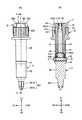
図1は、本発明の一実施形態に係る歯科インプラント用手術器具1と、トルクレンチTRと、フィクスチャーFを示す分解斜視図である。図2は、本発明の一実施形態に係る歯科インプラント用手術器具1の組立状態を示す図であり、(A)は側面図、(B)は(A)のI―I矢視断面図である。 FIG. 1 is an exploded perspective view showing a surgical instrument 1 for dental implants, a torque wrench TR, and a fixture F according to an embodiment of the present invention. 2A and 2B are views showing an assembled state of a surgical instrument 1 for a dental implant according to an embodiment of the present invention, in which FIG. 2A is a side view and FIG. 2B is a sectional view taken along the line II of FIG. is there.
図1に示すように歯科インプラント用手術器具1は、患者の口腔内に挿入されたフィクスチャーFに回転力を伝達させる歯科ドライバー2と、該歯科ドライバー2と連結されトルクレンチTRを嵌合可能なアダプタ3と、アダプタ3内に内在される連結部材4とを含む。 As shown in FIG. 1, the surgical instrument 1 for dental implants can be fitted with a
トルクレンチTRは、インプラント手術時にフィクスチャーFを顎骨内に深く埋入させるなど慎重を期す歯科ドライバー2の回転作業に使用される。トルクレンチTRは、本体部TR1と、先端部に設けられたアダプタ3と連結されるリング形状の連結部TR2を有している。連結部TR2は、後述するアダプタ3のレンチ連結部33と嵌合可能な形状を内壁面に有している。 The torque wrench TR is used for the rotation work of the
フィクスチャーFは、細長い筒状に形成されており、患者の口腔側(図示上、下側)の先端部が閉じられ、且つ、先端部とは反対側の基端部F1が開放された形状を有している。フィクスチャーFの外周部には、雄ねじ部F2が形成されている。フィクスチャーFの雄ねじ部F2は、患者の顎骨にねじ込まれて固定される。基端部F1の内周面は多角形状の雌固定部などに形成されて、歯科ドライバー2の先端側(矢印Y2側)と連結可能な構成とされている。勿論、基端部F1は、歯科ドライバー2のみならずマウント部材など他の手術器具と連結することも可能である。 The fixture F is formed in an elongated tubular shape, and has a shape in which the tip of the patient's oral cavity (lower side in the figure) is closed and the proximal end F1 opposite to the tip is open. have. A male screw portion F2 is formed on the outer peripheral portion of the fixture F. The male threaded portion F2 of the fixture F is screwed into and fixed to the patient's mandible. The inner peripheral surface of the base end portion F1 is formed in a polygonal female fixing portion or the like, and is configured to be connectable to the tip end side (arrow Y2 side) of the
なお、以下の説明において、矢印Y2側は、フィクスチャー側を指し、矢印Y1側は、トルク発生側を指す。トルク発生側とは、トルクレンチTRやハンドピースなどトルクを発生させる器具が接続される側を指す。 In the following description, the arrow Y2 side points to the fixture side, and the arrow Y1 side points to the torque generating side. The torque generating side refers to the side to which an instrument for generating torque such as a torque wrench TR or a handpiece is connected.
次に、本実施形態に係る歯科インプラント用手術器具1について図面に基づいて説明する。本実施形態の歯科インプラント用手術器具1は、図2に示すように歯科ドライバー2、アダプタ3、連結部材4とが一体化される構成である。即ち、歯科ドライバー2の上部軸部21の外周位置に、連結部材4が内在されたアダプタ3を嵌め入れて一体化する。本実施形態においては、歯科ドライバー2を把持する把持機構の位置と、歯科ドライバー2とアダプタ3におけるトルクの掛かる位置とが異なるように配置したことを特長としている。 Next, the surgical instrument 1 for dental implants according to the present embodiment will be described with reference to the drawings. As shown in FIG. 2, the surgical instrument 1 for dental implants of the present embodiment has a configuration in which a
(アダプタ)
先ず、本実施形態に係る歯科インプラント用手術器具1を構成するアダプタ3について図1〜図3に基づいて説明する。図3は、本発明の一実施形態に係る歯科インプラント用手術器具1を構成するアダプタ3を説明する図であり、(A)は上方斜視図、(B)は下方斜視図、(C)は底面図である。(adapter)
First, the
アダプタ3は、貫通孔31を備えた筒形形状の本体部30を有している。また本実施形態のアダプタ3は、雌固定部32とレンチ連結部33を有している。 The
雌固定部32は、貫通孔31内のフィクスチャー側(矢印Y2側)の端部に設けられている。雌固定部32の形状は、後述の歯科ドライバー2の雄固定部211と嵌合可能な形状とされている。本実施形態では6角形状とされているがこの限りではなく、3角以上の多角形状であればよい。 The
レンチ連結部33は、本体部30のトルク発生側(矢印Y1側)の外周面に設けられており、トルクレンチTRを接続する。レンチ連結部33は、本体部30のトルク発生側(矢印Y1側)の外周面に軸方向延在する突条部331が一定の間隔で設けられている。なおトルクレンチTRの連結部TR2の内壁面には、図示することは省略したが前記した複数の突条部331と嵌まり合う複数の凹部が形成されており、両者を嵌合することでトルクレンチTRはレンチ連結部33に接続される。 The
レンチ連結部33の上縁部には、軸方向と直交する方向に延びる溝部332が設けられている。この溝部332は、後述する連結部材4の上縁部を位置決め支持する。また溝部332には、後述する連結部材4のフランジ部44を載置する載置部332aを有している。 A
また、載置部332aは、図2(B)に示すように、貫通孔31の内壁31aより内方(中心軸寄り)に突出した止め部332bが形成されている。止め部332bは、内壁31aの内周面に沿って環状形状に形成されている。なお、止め部332bは、後述する連結部材4の凹部45と嵌合される構成である。 Further, as shown in FIG. 2B, the mounting
レンチ連結部33が設けられている本体部30の径は、雌固定部32が設けられている本体部30の径より大きく形成されている。これは、トルクレンチTRの連結部TR2との関係に依存するが、手動でトルク力を発生させる際にレンチ連結部33を容易に摘み持てるようにするためでもある。 The diameter of the
(歯科ドライバー)
次に、本実施形態に係る歯科インプラント用手術器具1を構成する歯科ドライバー2について図1、図2及び図4に基づいて説明する。図4は、本発明の一実施形態に係る歯科インプラント用手術器具1を構成する歯科ドライバー2を説明する図であり、(A)は上方斜視図、(B)は下方斜視図、(C)は平面図である。(Dental screwdriver)
Next, the
歯科ドライバー2は、トルク発生側に形成されたアダプタ3の貫通孔31内に収納される上部軸部21と、フィクスチャー側(矢印Y2側)の端部に形成された回転伝達軸部22を備えた軸本体部23を有している。なお、歯科ドライバー2は、アダプタ3が接合されていない場合には、トルク発生側(矢印Y1側)にハンドピースが接続可能な構成とされている。 The
上部軸部21は、雄固定部211と、突起部212と、ハンドピース連結部213を有している。 The
雄固定部211は、上部軸部21の回転伝達軸部22側に形成される。雄固定部211は、アダプタ3の雌固定部32と嵌合してアダプタ3を固定可能な多角形状とされている。本実施形態では6角形状である。 The
突起部212は、上部軸部21において雄固定部211と異なる位置に形成されており、軸方向と直交する方向に突出している。突起部212は、上部軸部21の外周面を囲む環状形状に形成されてよい。図示例の突起部212は、雄固定部211より上方位置(矢印Y1寄りのトルク発生側)に形成されている。この突起部212は、図2(B)に示すように後述する連結部材4の把持部42とで把持機構を構成する部材となる。したがって突起部212の位置が把持機構の位置Hとなる。 The protruding
なお、本実施形態の歯科インプラント用手術器具1においてトルクが掛かる位置とは、アダプタ3の雌固定部32と歯科ドライバー2の雄固定部211との連結箇所Rである。したがって、本実施形態の歯科インプラント用手術器具1は、把持機構の位置Hとトルクが掛かる連結箇所Rとは異なる位置に配置される。 The position where torque is applied in the surgical instrument 1 for dental implants of the present embodiment is the connection point R between the female fixing
ハンドピース連結部213は、上部軸部21のトルク発生側(矢印Y1側)の端部に形成されており、ハンドピースと連結可能な形状を有している。本実施形態のハンドピース連結部213は、Dカットが施された半円弧形状とされている。 The
回転伝達軸部22は、フィクスチャー側(矢印Y2側)の端部に連結軸部221を有している。連結軸部221は、多角形状に形成された連結片221aと先端部221bを有している。連結片221aは、フィクスチャーFの基端部F1の内周面に形成された雌固定部と対応する形状に形成されている。本実施形態の連結片221aと基端部F1の内周面の雌固定部は、6角形状とされている。連結片221aと先端部221bは、フィクスチャーFの基端部F1の開口部内に挿入され、少なくとも連結片221aとフィクスチャーFの雌固定部とが嵌合されることにより、フィクスチャーFと歯科ドライバー2との供回りが可能となる。なお、先端部221bは、連結片221aより小径とされ、円柱形状に形成されていてよい。 The rotation
上部軸部21と回転伝達軸部22との間には、軸方向と直交する方向に延在するフランジ部24が形成されている。フランジ部24は、上面に上部軸部21の外周位置に配置されるアダプタ3の下端面が当接される。したがってフランジ部24は、アダプタ3の位置決め機能を発揮する。図示例のフランジ部24は、環状形状とされているが、この限りではなく多角形状であってよい。 A
(連結部材)
次に、本実施形態に係る歯科インプラント用手術器具1を構成する連結部材4について図1、図2及び図5に基づいて説明する。図5は、本発明の一実施形態に係る歯科インプラント用手術器具1を構成する連結部材4を説明する図であり、(A)は上方斜視図、(B)は下方斜視図、(C)は底面図である。(Connecting member)
Next, the connecting member 4 constituting the surgical instrument 1 for dental implants according to the present embodiment will be described with reference to FIGS. 1, 2 and 5. 5A and 5B are views for explaining the connecting member 4 constituting the surgical instrument 1 for dental implants according to the embodiment of the present invention, where FIG. 5A is an upward perspective view, FIG. 5B is a downward perspective view, and FIG. Is a bottom view.
本実施形態の連結部材4は、アダプタ3の貫通孔31内に収納されて、歯科ドライバー2を連結する部材である。連結部材4は、図2(B)に示すように貫通孔31内であって、且つ歯科ドライバー2の上部軸部21の外周位置に配置される。また、連結部材4は、アダプタ3の貫通孔31に対して着脱可能な部材である。 The connecting member 4 of the present embodiment is a member that is housed in the through
連結部材4は、貫通孔41を有する筒形形状の本体部40を有している。連結部材4の本体部40のフィクスチャー側(矢印Y2側)の端部には把持部42が形成されている。 The connecting member 4 has a tubular
把持部42は、軸方向に延びる複数のスリット421と、貫通孔41内であって周方向に隣接するスリット421の間に形成された突起部212を掛け止める止め部422と、当該止め部422の直上位置に形成された窪み部423とを有する。 The
スリット421は、図示例では4つ設けられているが、この限りではなく2か所あればよい。把持部42は、スリット421により弾性変形が可能となる。止め部422は、貫通孔41の内周面の下端部に形成され、中心軸(仮想)に向かって内方に突出する形状とされている(図2(B)参照)。また止め部422は、内周方向に沿って延在する形状である。窪み部423は、外方へ湾曲する形状とされており、歯科ドライバー2の突起部212の外周面と対応する形状とされている。 In the illustrated example, four
上記構成の連結部材4を内在したアダプタ3を、歯科ドライバー2の上部軸部21に嵌め込む際、連結部材4の把持部42の止め部422が歯科ドライバー2の突起部212と接触する。すると、把持部42には突起部212により外方(矢印X1、X2方向)へ開く力が作用する。その際、把持部42はスリット421により外方に向かって弾性変形する。したがって、把持部42は突起部212を跨いで進入できる。また、把持部42は、突起部212を跨いで進入した後は、内方への弾性力により止め部422と窪み部423が図2(B)の位置に止まり、両者で歯科ドライバー2の突起部212を把持する。 When the
本実施形態の連結部材4は、アダプタ3の貫通孔31内に着脱可能に内在する構成を有している。その点を、図2、図5、図6から説明する。図6は、連結部材4をアダプタ3の貫通孔31内に内在させた状態を示す上方斜視図である。 The connecting member 4 of the present embodiment has a structure that is detachably embedded in the through
連結部材4のトルク発生側(矢印Y1側)の端部には、軸方向に延びる複数のスリット43が設けられており、周方向に隣接するスリット43の間には軸方向と直交する方向(矢印X1X2方向)に突出するフランジ部44を有している。図示例ではスリット43は、180°対向する位置に2箇所設けられており、周方向に隣接するスリット43の間に形成されるフランジ部44も対峙する2箇所に設けられている。対峙する2つのフランジ部44は、上記したアダプタ3の溝部332に嵌合可能な幅と形状を有している。 A plurality of
また、フランジ部44の直下位置には本体部40の外周方向に沿って凹部45が形成されている。凹部45は、上述したアダプタ3の載置部332aに形成された内方に突出する止め部332bと嵌合される(図2(B)参照)。 Further, a
連結部材4は、上記構成のスリット43とフランジ部44によりアダプタ3の貫通孔31内に着脱可能に内在できる。 The connecting member 4 can be detachably embedded in the through
図6に示すように、対峙する2つのフランジ部44は、上記したアダプタ3の溝部332内に嵌合され、フランジ部44の下面は溝部332に形成された載置部332a上に載置されることで、連結部材4はアダプタ3の貫通孔31内に内在される。このとき、連結部材4の凹部45は、アダプタ3の止め部332bと嵌合されている。 As shown in FIG. 6, the two
連結部材4を、アダプタ3の貫通孔31から取外す際には、2つのフランジ部44のそれぞれの外周面を摘んで中心方向(矢印N方向)へ力を加えると、フランジ部44はスリット43により矢印N方向へ弾性変形して、凹部45が止め部332bから離脱する。すると連結部材4を、アダプタ3の貫通孔31内から抜き出すことが可能となる。本実施形態の連結部材4は、樹脂製であることが好ましいが、金属製であってもよい。 When the connecting member 4 is removed from the through
上記してきたように本実施形態の歯科インプラント用手術器具1は、図2(B)に示すように歯科ドライバー2の突起部212と連結部材4の把持部42とで構成される把持機構の位置Hが、トルクの掛かる位置と異なる箇所となるように構成されている。トルクが掛かる位置とは、アダプタ3の雌固定部32と歯科ドライバー2の雄固定部211との連結箇所Rである。 As described above, in the surgical instrument 1 for dental implants of the present embodiment, as shown in FIG. 2 (B), the position of the gripping mechanism composed of the
したがって本実施形態の歯科インプラント用手術器具1は、歯科ドライバー2に高トルクが伝達されても、把持機構が損傷することを防止でき、連結箇所Rにおける耐トルク力を保持して耐久性を確保できる。また、連結箇所Rにおけるトルク性能が安定するので、手術の作業性を保持できる。 Therefore, the surgical instrument 1 for dental implants of the present embodiment can prevent the gripping mechanism from being damaged even if a high torque is transmitted to the
また、本実施形態の歯科インプラント用手術器具1を構成する連結部材4は、アダプタ3に対して着脱可能であるため、手術後に取外して、クリーニングなどを容易に行なうことができ衛生的である。 Further, since the connecting member 4 constituting the surgical instrument 1 for dental implants of the present embodiment is detachable from the
(変形例)
次に、本実施形態の歯科インプラント用手術器具1を実施する際の変形例を図7、図8から説明する。図7は、本発明の一実施形態に係る歯科インプラント用手術器具1を構成するアダプタ3をマウント部材5と連結する変形例を説明する分解斜視図である。図8、本発明の一実施形態に係る歯科インプラント用手術器具1を構成するアダプタ3をマウント部材5と連結した状態を例示する変形例の組立図である。図7は説明の関係上、一部透過斜視図とした。また、図8は、説明の関係上、一部を透過断面図とした。(Modification example)
Next, a modification of the surgical instrument 1 for dental implants of the present embodiment will be described with reference to FIGS. 7 and 8. FIG. 7 is an exploded perspective view illustrating a modified example in which the
本実施形態の歯科インプラント用手術器具1を構成するアダプタ3は、図1〜図6では、歯科ドライバー2と接続される構成を説明した。しかし、本実施形態のアダプタ3は、フィクスチャーFの基端部F1に接続されたマウント部材5とも連結できる。 In FIGS. 1 to 6, the
マウント部材5は、中実棒形状の軸本体部50を有している。軸本体部50のフィクスチャー側の端部にネジ部51、該ネジ部51の直上位置にフィクスチャーFの基端部F1の雌固定部と嵌合可能な形状に形成された第1雄固定部52を有している。図示例の第1雄固定部52は6角形状とされているが、この限りではなく3角形状以上であればよい。ネジ部51は、フィクスチャーFの基端部F1内の内壁面に形成された雌ネジ部に螺着される。 The
軸本体部50のトルク発生側(矢印Y1側)の端部には、手動用のドライバーの先端と連結される受け溝54aが形成されたドライバー連結部54を有している。また、軸本体部50は、ドライバー連結部54の下方位置に形成された、アダプタ3の雌固定部32と嵌合可能な形状に形成された多角形状の第2雄固定部53を有している。変形例において、アダプタ3の雌固定部32とマウント部材5の第2雄固定部53との連結箇所が、トルクの掛かる位置となる。 At the end of the
軸本体部50の第2雄固定部53とドライバー連結部54との間には、軸方向と直交する方向に突出する突起部55が設けられている。突起部55は、軸本体部50の外周面を囲む環状形状に形成されてよい。この突起部55は、連結部材4の把持部42に把持される。把持機構としては、歯科ドライバー2の突起部212と連結部材4の把持部42と同様の構成を有している。 A
更に軸本体部50の突起部55の直下位置(矢印Y2側)には、軸方向と直交する方向に延在するフランジ部56が形成されている。フランジ部56は、上面にアダプタ3の下端面が当接される。したがってフランジ部56は、アダプタ3の位置決め機能を発揮する。フランジ部56は、多角形状とされているが円形であってもよい。 Further, a
上記構成のマウント部材5は、軸本体部50のフランジ部56より上方部分に、本実施形態のアダプタ3を嵌め入れて両者を連結できる。即ち、マウント部材5の第2雄固定部53が、アダプタ3の雌固定部32と嵌合することにより連結できる。このときマウント部材5の突起部55は、連結部材4の止め部422と窪み部423により把持されている。したがって変形例においても、把持機構の位置は、トルクの掛かる位置とは異なる位置に配置される。 The
なお、本実施形態のアダプタ3の雌固定部32は、歯科ドライバー2の雄固定部211とマウント部材5の第2雄固定部53の両方と嵌合可能な形状を有している。本実施形態では、歯科ドライバー2の雄固定部211とマウント部材5の第2雄固定部53とは、同じ形状を有している。 The
ところで、従来フィクスチャーからマウント部材を取外す場合、マウント部材の外周面を、フィクスチャーが供回りしないように別途用意したレンチなどをかませたうえで、マウント部材を手動ドライバーで回してフィクスチャーから取るという方法を用いていた。この方法は、供回りしないようにレンチをかませる操作と、マウント部材の取外し操作を同時に行う必要があるため作業性が非常に悪かった。 By the way, when removing the mount member from the conventional fixture, the outer peripheral surface of the mount member is bitten by a wrench or the like prepared separately so that the fixture does not rotate, and then the mount member is turned with a manual screwdriver to remove the mount member from the fixture. I used the method of taking. In this method, the workability is very poor because it is necessary to simultaneously perform the operation of biting the wrench so as not to rotate and the operation of removing the mount member.
本実施形態の歯科インプラント用手術器具1を構成するアダプタ3は、フィクスチャーFの基端部F1に接続されたマウント部材5とも連結できる構成である。また、本実施形態のアダプタ3は、貫通孔31(及び連結部材4の貫通孔41)を有しているため、貫通孔31内に手動用のドライバーなどを指し込み可能な構成である。 The
したがって、フィクスチャーF1からマウント部材5を取外す場合、アダプタ3の貫通孔31内に手動用のドライバーを差し入れ、先端をマウント部材5の受け溝54aに嵌合させて回す操作のみで容易に行える。そして、アダプタ3とマウント部材5とは連結されているので、同時にフィクスチャーF1から取外せる。 Therefore, when removing the
また、アダプタ3をマウント部材5と連結している状態でも、貫通孔31から手動用のドライバーを差し入れて微調整できる利点もある。 Further, even when the
以上、本発明の好ましい実施形態について詳述したが、本発明は上記した特定の実施形態に限定されるものではなく、特許請求の範囲に記載された本発明の要旨の範囲内において、種々の変形・変更が可能なものである。 Although the preferred embodiments of the present invention have been described in detail above, the present invention is not limited to the above-mentioned specific embodiments, and various aspects are within the scope of the gist of the present invention described in the claims. It can be transformed and changed.
1 歯科インプラント用手術器具
2 歯科ドライバー
21 上部軸部
211 雄固定部
212 突起部
213 ハンドピース連結部
22 回転伝達軸部
221 連結軸部
221a 連結片
221b 先端部
23 軸本体部
24 フランジ部
3 アダプタ
31 貫通孔
32 雌固定部
33 レンチ連結部
331 突条部
332 溝部
332a 載置部
332b 止め部
4 連結部材
40 本体部
41 貫通孔
42 把持部
421 スリット
422 止め部
423 窪み部
43 スリット
44 フランジ部
45 凹部
5 マウント部材
50 軸本体部
51 ネジ部
52 第1雄固定部
53 第2雄固定部
54 ドライバー連結部
54a 受け溝
55 突起部
56 フランジ部
TR トルクレンチ
F フィクスチャー1 Surgical instrument for
Claims (2)
Translated fromJapanese前記アダプタは、
貫通孔を有する筒形形状とされ、
前記貫通孔内のフィクスチャー側の端部に前記歯科ドライバーに固定される多角形状の雌固定部と、
前記フィクスチャー側と反対側の端部に前記トルクレンチを嵌合するレンチ連結部と、
を有しており、
前記歯科ドライバーは、
前記アダプタの前記貫通孔内に収納可能な上部軸部、及び前記フィクスチャー側の端部に形成された回転伝達軸部を備えた軸本体部と、
前記上部軸部の前記回転伝達軸部側に形成された、前記雌固定部と嵌合して前記アダプタを固定する多角形状の雄固定部と、
前記上部軸部の前記雄固定部と異なる位置に形成された軸方向と直交する方向に突出する突起部とを有しており、
前記アダプタの前記貫通孔内には、前記上部軸部の前記突起部を把持して前記歯科ドライバーを連結する把持部を有する貫通形状の連結部材が内在され、
前記連結部材の前記フィクスチャー側と反対側の端部には、
軸方向に延びる複数のスリットと、軸方向と直交する方向に突出するフランジ部とを有していることを特徴とする歯科インプラント用手術器具。A surgical instrument for dental implants having a dental screwdriver that transmits a rotational force to a fixture inserted into the patient's oral cavity and an adapter that is connected to the dental screwdriver and can be fitted with a torque wrench.
The adapter
It has a tubular shape with through holes.
A polygonal female fixing portion fixed to the dental driver at the fixture-side end in the through hole,
A wrench connecting portion for fitting the torque wrench to the end opposite to the fixture side,
Have and
The dental driver
An upper shaft portion that can be housed in the through hole of the adapter, and a shaft body portion having a rotation transmission shaft portion formed at the end on the fixture side.
A polygonal male fixing portion formed on the rotation transmission shaft portion side of the upper shaft portion and fitted with the female fixing portion to fix the adapter.
The upper shaft portion has a protrusion formed at a position different from that of the male fixing portion and projecting in a direction orthogonal to the axial direction.
In the through hole of the adapter, a through-shaped connecting member having a grip portion that grips the protrusion of the upper shaft portion and connects the dental driver is contained therein.
At the end of the connecting member on the side opposite to the fixture side,
A surgical instrument for dental implants, characterizedby having aplurality of slits extending in the axial direction and a flange portion protruding in a direction orthogonal to the axial direction .
前記連結部材の前記フランジ部を載置する載置部が形成されていることを特徴とする請求項1に記載の歯科インプラント用手術器具。At the end of the adapter opposite to the fixture side
The surgical instrument for dental implants according to claim1 , wherein a mounting portion on which the flange portion of the connecting member is mounted is formed.
Priority Applications (2)
| Application Number | Priority Date | Filing Date | Title |
|---|---|---|---|
| JP2016236477AJP6793024B2 (en) | 2016-12-06 | 2016-12-06 | Surgical instruments for dental implants |
| EP17203107.2AEP3332735B1 (en) | 2016-12-06 | 2017-11-22 | Surgical instrument for dental implant |
Applications Claiming Priority (1)
| Application Number | Priority Date | Filing Date | Title |
|---|---|---|---|
| JP2016236477AJP6793024B2 (en) | 2016-12-06 | 2016-12-06 | Surgical instruments for dental implants |
Publications (2)
| Publication Number | Publication Date |
|---|---|
| JP2018089205A JP2018089205A (en) | 2018-06-14 |
| JP6793024B2true JP6793024B2 (en) | 2020-12-02 |
Family
ID=60450509
Family Applications (1)
| Application Number | Title | Priority Date | Filing Date |
|---|---|---|---|
| JP2016236477AActiveJP6793024B2 (en) | 2016-12-06 | 2016-12-06 | Surgical instruments for dental implants |
Country Status (2)
| Country | Link |
|---|---|
| EP (1) | EP3332735B1 (en) |
| JP (1) | JP6793024B2 (en) |
Families Citing this family (3)
| Publication number | Priority date | Publication date | Assignee | Title |
|---|---|---|---|---|
| JP7191621B2 (en)* | 2018-09-28 | 2022-12-19 | 株式会社ジーシー | Artificial tooth root implantation driver, artificial tooth root with driver |
| EP3639786A1 (en)* | 2018-10-15 | 2020-04-22 | Straumann Holding AG | Instrument for screwing in a dental implant and its retention element for the implant driver |
| CN114209459B (en)* | 2021-12-31 | 2022-09-16 | 山东大学 | A universal manual implanter for oral implantation and its application |
Family Cites Families (3)
| Publication number | Priority date | Publication date | Assignee | Title |
|---|---|---|---|---|
| EP0811358A1 (en)* | 1996-06-06 | 1997-12-10 | Institut Straumann AG | Demountable driver for the chirurgical insertion of an implant |
| US6524035B1 (en)* | 1998-01-27 | 2003-02-25 | Thomas Vigil | Conduit reamer tool assembly |
| EP2085042B1 (en)* | 2008-01-29 | 2010-09-15 | Hader SA | Dynamometric tool for medical use |
- 2016
- 2016-12-06JPJP2016236477Apatent/JP6793024B2/enactiveActive
- 2017
- 2017-11-22EPEP17203107.2Apatent/EP3332735B1/enactiveActive
Also Published As
| Publication number | Publication date |
|---|---|
| EP3332735B1 (en) | 2019-07-03 |
| JP2018089205A (en) | 2018-06-14 |
| EP3332735A1 (en) | 2018-06-13 |
Similar Documents
| Publication | Publication Date | Title |
|---|---|---|
| US6159008A (en) | Implant carrier with gripping fingers | |
| US6217332B1 (en) | Combination implant carrier and vial cap | |
| US6955258B2 (en) | Dental implant packaging system | |
| JP6334543B2 (en) | Insert tool | |
| US7887325B2 (en) | Implant-driver assembly | |
| ES2661918T3 (en) | Screw to fix a prosthesis on a dental implant, conveyor, kit and tightening wrench | |
| US20100291507A1 (en) | Polyaxial Dental Implant | |
| JP6793024B2 (en) | Surgical instruments for dental implants | |
| KR101181924B1 (en) | Implant operation tool | |
| ES2987362T3 (en) | Annular elastic retaining member | |
| TW201511739A (en) | Implant driver, implant | |
| KR100988305B1 (en) | Screwdriver for orthodontic screw | |
| JP3671004B2 (en) | Columnar elements specifically for determining the spatial position of the implant | |
| CN109069234B (en) | Handling tool, dental kit and method for assembling dental components | |
| KR100988306B1 (en) | Fixture screwdriver | |
| CN113164231B (en) | Tool and retaining element for dental implant treatment | |
| KR101072274B1 (en) | Detachable Dental Implants | |
| KR101123508B1 (en) | Surgical hand drill | |
| TWI834836B (en) | Tool assembly for mounting a dental abutment | |
| JP6348281B2 (en) | Surgical instrument for dental implant | |
| JP2004141479A (en) | Implanting system of dental implant | |
| KR101963696B1 (en) | Guide ring for dental surgery | |
| RU2005106357A (en) | TOOLS FOR PERFORMANCE OF DENTAL IMPLANTS | |
| KR200428092Y1 (en) | Dental Implant Fixtures Without Mounts |
Legal Events
| Date | Code | Title | Description |
|---|---|---|---|
| A621 | Written request for application examination | Free format text:JAPANESE INTERMEDIATE CODE: A621 Effective date:20190725 | |
| A977 | Report on retrieval | Free format text:JAPANESE INTERMEDIATE CODE: A971007 Effective date:20200708 | |
| A131 | Notification of reasons for refusal | Free format text:JAPANESE INTERMEDIATE CODE: A131 Effective date:20200728 | |
| A521 | Request for written amendment filed | Free format text:JAPANESE INTERMEDIATE CODE: A523 Effective date:20200827 | |
| TRDD | Decision of grant or rejection written | ||
| A01 | Written decision to grant a patent or to grant a registration (utility model) | Free format text:JAPANESE INTERMEDIATE CODE: A01 Effective date:20201104 | |
| A61 | First payment of annual fees (during grant procedure) | Free format text:JAPANESE INTERMEDIATE CODE: A61 Effective date:20201109 | |
| R150 | Certificate of patent or registration of utility model | Ref document number:6793024 Country of ref document:JP Free format text:JAPANESE INTERMEDIATE CODE: R150 | |
| R250 | Receipt of annual fees | Free format text:JAPANESE INTERMEDIATE CODE: R250 |