JP6790833B2 - Storage battery control system, storage battery control method, and recording medium - Google Patents
Storage battery control system, storage battery control method, and recording mediumDownload PDFInfo
- Publication number
- JP6790833B2 JP6790833B2JP2016569294AJP2016569294AJP6790833B2JP 6790833 B2JP6790833 B2JP 6790833B2JP 2016569294 AJP2016569294 AJP 2016569294AJP 2016569294 AJP2016569294 AJP 2016569294AJP 6790833 B2JP6790833 B2JP 6790833B2
- Authority
- JP
- Japan
- Prior art keywords
- capacity
- storage
- deterioration rate
- power
- storage battery
- Prior art date
- Legal status (The legal status is an assumption and is not a legal conclusion. Google has not performed a legal analysis and makes no representation as to the accuracy of the status listed.)
- Active
Links
Images


Classifications
- H—ELECTRICITY
- H01—ELECTRIC ELEMENTS
- H01M—PROCESSES OR MEANS, e.g. BATTERIES, FOR THE DIRECT CONVERSION OF CHEMICAL ENERGY INTO ELECTRICAL ENERGY
- H01M10/00—Secondary cells; Manufacture thereof
- H01M10/42—Methods or arrangements for servicing or maintenance of secondary cells or secondary half-cells
- H01M10/44—Methods for charging or discharging
- H01M10/441—Methods for charging or discharging for several batteries or cells simultaneously or sequentially
- H—ELECTRICITY
- H01—ELECTRIC ELEMENTS
- H01M—PROCESSES OR MEANS, e.g. BATTERIES, FOR THE DIRECT CONVERSION OF CHEMICAL ENERGY INTO ELECTRICAL ENERGY
- H01M10/00—Secondary cells; Manufacture thereof
- H01M10/42—Methods or arrangements for servicing or maintenance of secondary cells or secondary half-cells
- H01M10/425—Structural combination with electronic components, e.g. electronic circuits integrated to the outside of the casing
- H—ELECTRICITY
- H01—ELECTRIC ELEMENTS
- H01M—PROCESSES OR MEANS, e.g. BATTERIES, FOR THE DIRECT CONVERSION OF CHEMICAL ENERGY INTO ELECTRICAL ENERGY
- H01M10/00—Secondary cells; Manufacture thereof
- H01M10/42—Methods or arrangements for servicing or maintenance of secondary cells or secondary half-cells
- H01M10/48—Accumulators combined with arrangements for measuring, testing or indicating the condition of cells, e.g. the level or density of the electrolyte
- H01M10/482—Accumulators combined with arrangements for measuring, testing or indicating the condition of cells, e.g. the level or density of the electrolyte for several batteries or cells simultaneously or sequentially
- H—ELECTRICITY
- H02—GENERATION; CONVERSION OR DISTRIBUTION OF ELECTRIC POWER
- H02J—CIRCUIT ARRANGEMENTS OR SYSTEMS FOR SUPPLYING OR DISTRIBUTING ELECTRIC POWER; SYSTEMS FOR STORING ELECTRIC ENERGY
- H02J3/00—Circuit arrangements for AC mains or AC distribution networks
- H02J3/28—Arrangements for balancing of the load in a network by storage of energy
- H02J3/32—Arrangements for balancing of the load in a network by storage of energy using batteries with converting means
- H—ELECTRICITY
- H02—GENERATION; CONVERSION OR DISTRIBUTION OF ELECTRIC POWER
- H02J—CIRCUIT ARRANGEMENTS OR SYSTEMS FOR SUPPLYING OR DISTRIBUTING ELECTRIC POWER; SYSTEMS FOR STORING ELECTRIC ENERGY
- H02J7/00—Circuit arrangements for charging or depolarising batteries or for supplying loads from batteries
- H02J7/0013—Circuit arrangements for charging or depolarising batteries or for supplying loads from batteries acting upon several batteries simultaneously or sequentially
- H02J7/0014—Circuits for equalisation of charge between batteries
- H—ELECTRICITY
- H02—GENERATION; CONVERSION OR DISTRIBUTION OF ELECTRIC POWER
- H02J—CIRCUIT ARRANGEMENTS OR SYSTEMS FOR SUPPLYING OR DISTRIBUTING ELECTRIC POWER; SYSTEMS FOR STORING ELECTRIC ENERGY
- H02J7/00—Circuit arrangements for charging or depolarising batteries or for supplying loads from batteries
- H02J7/0047—Circuit arrangements for charging or depolarising batteries or for supplying loads from batteries with monitoring or indicating devices or circuits
- H02J7/0048—Detection of remaining charge capacity or state of charge [SOC]
- H—ELECTRICITY
- H02—GENERATION; CONVERSION OR DISTRIBUTION OF ELECTRIC POWER
- H02J—CIRCUIT ARRANGEMENTS OR SYSTEMS FOR SUPPLYING OR DISTRIBUTING ELECTRIC POWER; SYSTEMS FOR STORING ELECTRIC ENERGY
- H02J7/00—Circuit arrangements for charging or depolarising batteries or for supplying loads from batteries
- H02J7/0047—Circuit arrangements for charging or depolarising batteries or for supplying loads from batteries with monitoring or indicating devices or circuits
- H02J7/005—Detection of state of health [SOH]
- H—ELECTRICITY
- H02—GENERATION; CONVERSION OR DISTRIBUTION OF ELECTRIC POWER
- H02J—CIRCUIT ARRANGEMENTS OR SYSTEMS FOR SUPPLYING OR DISTRIBUTING ELECTRIC POWER; SYSTEMS FOR STORING ELECTRIC ENERGY
- H02J7/00—Circuit arrangements for charging or depolarising batteries or for supplying loads from batteries
- H02J7/007—Regulation of charging or discharging current or voltage
- H—ELECTRICITY
- H01—ELECTRIC ELEMENTS
- H01M—PROCESSES OR MEANS, e.g. BATTERIES, FOR THE DIRECT CONVERSION OF CHEMICAL ENERGY INTO ELECTRICAL ENERGY
- H01M10/00—Secondary cells; Manufacture thereof
- H01M10/05—Accumulators with non-aqueous electrolyte
- H01M10/052—Li-accumulators
- H01M10/0525—Rocking-chair batteries, i.e. batteries with lithium insertion or intercalation in both electrodes; Lithium-ion batteries
- H—ELECTRICITY
- H01—ELECTRIC ELEMENTS
- H01M—PROCESSES OR MEANS, e.g. BATTERIES, FOR THE DIRECT CONVERSION OF CHEMICAL ENERGY INTO ELECTRICAL ENERGY
- H01M10/00—Secondary cells; Manufacture thereof
- H01M10/42—Methods or arrangements for servicing or maintenance of secondary cells or secondary half-cells
- H01M10/425—Structural combination with electronic components, e.g. electronic circuits integrated to the outside of the casing
- H01M2010/4278—Systems for data transfer from batteries, e.g. transfer of battery parameters to a controller, data transferred between battery controller and main controller
- H—ELECTRICITY
- H01—ELECTRIC ELEMENTS
- H01M—PROCESSES OR MEANS, e.g. BATTERIES, FOR THE DIRECT CONVERSION OF CHEMICAL ENERGY INTO ELECTRICAL ENERGY
- H01M2220/00—Batteries for particular applications
- H01M2220/20—Batteries in motive systems, e.g. vehicle, ship, plane
- Y—GENERAL TAGGING OF NEW TECHNOLOGICAL DEVELOPMENTS; GENERAL TAGGING OF CROSS-SECTIONAL TECHNOLOGIES SPANNING OVER SEVERAL SECTIONS OF THE IPC; TECHNICAL SUBJECTS COVERED BY FORMER USPC CROSS-REFERENCE ART COLLECTIONS [XRACs] AND DIGESTS
- Y02—TECHNOLOGIES OR APPLICATIONS FOR MITIGATION OR ADAPTATION AGAINST CLIMATE CHANGE
- Y02E—REDUCTION OF GREENHOUSE GAS [GHG] EMISSIONS, RELATED TO ENERGY GENERATION, TRANSMISSION OR DISTRIBUTION
- Y02E60/00—Enabling technologies; Technologies with a potential or indirect contribution to GHG emissions mitigation
- Y02E60/10—Energy storage using batteries
- Y—GENERAL TAGGING OF NEW TECHNOLOGICAL DEVELOPMENTS; GENERAL TAGGING OF CROSS-SECTIONAL TECHNOLOGIES SPANNING OVER SEVERAL SECTIONS OF THE IPC; TECHNICAL SUBJECTS COVERED BY FORMER USPC CROSS-REFERENCE ART COLLECTIONS [XRACs] AND DIGESTS
- Y02—TECHNOLOGIES OR APPLICATIONS FOR MITIGATION OR ADAPTATION AGAINST CLIMATE CHANGE
- Y02T—CLIMATE CHANGE MITIGATION TECHNOLOGIES RELATED TO TRANSPORTATION
- Y02T10/00—Road transport of goods or passengers
- Y02T10/60—Other road transportation technologies with climate change mitigation effect
- Y02T10/70—Energy storage systems for electromobility, e.g. batteries
Landscapes
- Engineering & Computer Science (AREA)
- Power Engineering (AREA)
- Chemical & Material Sciences (AREA)
- Chemical Kinetics & Catalysis (AREA)
- Electrochemistry (AREA)
- General Chemical & Material Sciences (AREA)
- Manufacturing & Machinery (AREA)
- Health & Medical Sciences (AREA)
- General Health & Medical Sciences (AREA)
- Medical Informatics (AREA)
- Microelectronics & Electronic Packaging (AREA)
- Charge And Discharge Circuits For Batteries Or The Like (AREA)
- Secondary Cells (AREA)
- Supply And Distribution Of Alternating Current (AREA)
- Materials Engineering (AREA)
Description
Translated fromJapanese本発明は、蓄電池制御システム、蓄電池制御方法、及び、記録媒体に関する。 The present invention relates to a storage battery control system, a storage battery control method, and a recording medium.
近年、電気自動車やハイブリッド自動車等の電源として、蓄電池を用いる技術開発が行われている。また、このような蓄電池を電力系統に組み込まれた太陽電池や風力発電等のように、電力調整用の分散電源として利用する技術開発も行われている。 In recent years, technological developments using storage batteries as a power source for electric vehicles and hybrid vehicles have been carried out. Further, technological development is being carried out in which such a storage battery is used as a distributed power source for power adjustment, such as a solar cell incorporated in a power system or wind power generation.
電力調整用電源に対しては、10年以上の耐久性が要求されると共に、製造コストの抑制及びメンテナンスコストの削減が求められている。かかる要求に対応するためには、製品寿命を延ばすことが重要となる。 The power supply for power adjustment is required to have a durability of 10 years or more, and is also required to suppress manufacturing costs and reduce maintenance costs. In order to meet such demands, it is important to extend the product life.
製品寿命を延ばす最良な方法は、蓄電池を構成する電池セルの材料や構造の最適化を図ることである。しかし、かかる技術開発には、多大な時間及び費用が必要になる。そこで、製品寿命を延ばす技術開発と並行して、又は、先だって蓄電池の寿命劣化を抑制する技術開発が重要となる。 The best way to extend the product life is to optimize the material and structure of the battery cells that make up the storage battery. However, such technological development requires a great deal of time and money. Therefore, it is important to develop a technology for suppressing the deterioration of the life of the storage battery in parallel with or in advance of the development of the technology for extending the product life.
なお、寿命劣化は、蓄電池が蓄電できる電力量又は蓄電した電力の供給能力の劣化に対応する。そこで、以下の説明では、製品寿命の劣化を容量劣化と適宜記載する。 The deterioration of the life corresponds to the deterioration of the amount of electric power that can be stored in the storage battery or the supply capacity of the stored electric power. Therefore, in the following description, deterioration of product life is appropriately described as capacity deterioration.
蓄電池の容量劣化は、運用方法等に起因して大きく変わる。そこで、例えば、特許文献1や特許文献2においては、リチウムイオン二次電池に対する充放電方法を工夫することで容量劣化を抑制する技術が提案されている。 The capacity deterioration of the storage battery changes greatly depending on the operation method and the like. Therefore, for example,
即ち、特許文献1では、正極活物質と負極活物質との間で移動するリチウムイオン量が、可逆的に移動可能なリチウムイオン量の95%以下となるように、リチウムイオン二次電池の充放電を制御する。 That is, in
また、特許文献2では、放電時の放電終止電圧が3.2〜3.1V、充電時のセル上限電圧が4.0〜4.5Vとなるように、リチウムイオン二次電池の充放電を制御する。 Further, in
このように、蓄電池を電力調整用電源として普及させるには、蓄電池の容量劣化を抑制しながら、電力調整要求に応じられるようにすることが必要である。しかし、上述した各特許文献を含め、これまで提案されている種々の容量劣化抑制技術では、電力調整用電源に求められる10年以上の製品寿命に関する要求を満たすことが困難であった。 As described above, in order to popularize the storage battery as a power source for power adjustment, it is necessary to be able to meet the power adjustment request while suppressing the deterioration of the capacity of the storage battery. However, it has been difficult for various capacity deterioration suppressing techniques proposed so far, including the above-mentioned patent documents, to satisfy the requirements for a product life of 10 years or more required for a power supply for power adjustment.
そこで、本発明の主目的は、効率的に蓄電池の容量劣化を抑制できるようにした蓄電池制御システム、蓄電池制御方法、及び、記録媒体を提供することである。 Therefore, a main object of the present invention is to provide a storage battery control system, a storage battery control method, and a recording medium capable of efficiently suppressing capacity deterioration of the storage battery.
上記課題を解決するため、電力系統からの電力調整要求に基づき配下の複数の蓄電池に対して充放電制御を行う蓄電池制御システムにかかる発明は、蓄電池の蓄電池情報に基づき該蓄電池の現在の蓄電容量を算出する蓄電容量算出手段と、蓄電池の運転を停止する際の目標蓄電容量を設定する目標蓄電容量設定手段と、予め設定された容量劣化速度相関情報に現在蓄電容量及び目標蓄電容量を適用して、各蓄電容量に対する現在容量劣化速度及び目標容量劣化速度を算出する容量劣化速度算出手段と、運転開始時からの経過時間をt、容量劣化速度が蓄電容量に応じて変動する場合の当該容量劣化速度の時間積分値を容量劣化量DSOC変動(t)、容量劣化速度が蓄電容量にかかわらず一定とした場合の当該容量劣化速度の時間積分値を容量劣化量DSOC一定(t)とした際に、容量劣化量DSOC変動(t)≦容量劣化量DSOC一定(t)の容量劣化量抑制条件を満たすように複数の蓄電池に電力を配分する手段手段と、を備える。In order to solve the above problems, the invention relating to a storage battery control system that performs charge / discharge control for a plurality of storage batteries under the control based on a power adjustment request from the power system is based on the storage battery information of the storage battery and the current storage capacity of the storage battery. The current storage capacity and the target storage capacity are applied to the storage capacity calculation means for calculating the storage capacity, the target storage capacity setting means for setting the target storage capacity when the operation of the storage battery is stopped, and the preset capacity deterioration rate correlation information. The capacity deterioration rate calculation means for calculating the current capacity deterioration rate and the target capacity deterioration rate for each storage capacity, the elapsed time from the start of operation is t, and the capacity when the capacity deterioration rate fluctuates according to the storage capacity. The time-integrated value of the deterioration rate is the capacity deterioration amount DSOC fluctuation (t), and the time-integrated value of the capacity deterioration rate when the capacity deterioration rate is constant regardless of the storage capacity is defined as the capacity deterioration amount DSOC constant (t). At that time, the means means for allocating power to a plurality of storage batteries so as to satisfy the condition of suppressing the capacity deterioration amount of the capacity deterioration amount DSOC fluctuation (t) ≤ capacity deterioration amount DSOC constant (t) is provided.
また、電力系統からの電力調整要求に基づき配下の複数の蓄電池に対して充放電制御を行う蓄電池制御方法にかかる発明は、蓄電池の蓄電池情報に基づき該蓄電池の現在の蓄電容量を算出し、蓄電池の運転を停止する際の目標蓄電容量を設定し、予め設定された容量劣化速度相関情報に現在蓄電容量及び目標蓄電容量を適用して、各蓄電容量に対する現在容量劣化速度及び目標容量劣化速度を算出し、運転開始時からの経過時間をt、容量劣化速度が蓄電容量に応じて変動する場合の当該容量劣化速度の時間積分値を容量劣化量DSOC変動(t)、容量劣化速度が蓄電容量にかかわらず一定とした場合の当該容量劣化速度の時間積分値を容量劣化量DSOC一定(t)とした際に、容量劣化量DSOC変動(t)≦容量劣化量DSOC一定(t)の容量劣化量抑制条件を満たすように複数の蓄電池に電力を配分する。Further, in the invention relating to a storage battery control method in which charge / discharge control is performed for a plurality of storage batteries under the control based on a power adjustment request from the power system, the current storage capacity of the storage battery is calculated based on the storage battery information of the storage battery, and the storage battery Set the target storage capacity when stopping the operation, apply the current storage capacity and target storage capacity to the preset capacity deterioration rate correlation information, and set the current capacity deterioration rate and target capacity deterioration rate for each storage capacity. Calculated, the elapsed time from the start of operation is t, the time integration value of the capacity deterioration rate when the capacity deterioration rate fluctuates according to the storage capacity is the capacity deterioration amount DSOC fluctuation (t), and the capacity deterioration rate is the storage capacity. When the time integration value of the capacity deterioration rate is constant regardless of the capacity and the capacity deterioration amount DSOC is constant (t), the capacity deterioration amount DSOC fluctuation (t) ≤ capacity deterioration amount DSOC constant (t) ), The power is distributed to a plurality of storage batteries so as to satisfy the condition for suppressing the amount of capacity deterioration.
さらに、電力系統からの電力調整要求に基づき配下の複数の蓄電池に対する充放電制御をコンピュータに実行させる蓄電池制御プログラムが格納された記録媒体にかかる発明は、蓄電池制御プログラムが、蓄電池の蓄電池情報に基づき該蓄電池の現在の蓄電容量を算出するステップと、蓄電池の運転を停止する際の目標蓄電容量を設定するステップと、予め設定された容量劣化速度相関情報に現在蓄電容量及び目標蓄電容量を適用して、各蓄電容量に対する現在容量劣化速度及び目標容量劣化速度を算出するステップと、運転開始時からの経過時間をt、容量劣化速度が蓄電容量に応じて変動する場合の当該容量劣化速度の時間積分値を容量劣化量DSOC変動(t)、容量劣化速度が蓄電容量にかかわらず一定とした場合の当該容量劣化速度の時間積分値を容量劣化量DSOC一定(t)とした際に、容量劣化量DSOC変動(t)≦容量劣化量DSOC一定(t)の容量劣化量抑制条件を満たすように複数の蓄電池に電力を配分するステップと、を含む。Further, in the invention relating to the recording medium in which the storage battery control program for causing the computer to execute charge / discharge control for a plurality of storage batteries under the control based on the power adjustment request from the power system is stored, the storage battery control program is based on the storage battery information of the storage battery. The current storage capacity and the target storage capacity are applied to the step of calculating the current storage capacity of the storage battery, the step of setting the target storage capacity when the operation of the storage battery is stopped, and the preset capacity deterioration rate correlation information. The step of calculating the current capacity deterioration rate and the target capacity deterioration rate for each storage capacity, the elapsed time from the start of operation is t, and the time of the capacity deterioration rate when the capacity deterioration rate fluctuates according to the storage capacity. When the integrated value is the capacity deterioration amount DSOC fluctuation (t) and the time integrated value of the capacity deterioration rate is constant regardless of the storage capacity, the capacity deterioration amount DSOC is constant (t). The step of allocating power to a plurality of storage batteries so as to satisfy the capacity deterioration amount suppression condition of the capacity deterioration amount DSOC fluctuation (t) ≤ capacity deterioration amount DSOC constant (t) is included.
本発明によれば、蓄電池の容量劣化を抑制しつつ電力調整要求に応じた運転が可能になる。 According to the present invention, it is possible to operate in response to a power adjustment request while suppressing deterioration of the capacity of the storage battery.
<第1実施形態>
第1実施形態を説明する。この実施形態にかかる蓄電池制御システムは、電力系統からの電力調整要求に基づき配下の複数の蓄電池に対して充放電制御を行う。このとき蓄電池制御システムは、蓄電容量算出器、目標蓄電容量設定器、容量劣化速度算出器、電力配分器を備える。蓄電容量算出器は、蓄電池の蓄電池情報に基づき該蓄電池の現在の蓄電容量を算出する。目標蓄電容量設定器は、蓄電池の運転を停止する際の目標蓄電容量を設定する予め設定された容量劣化速度相関情報に現在蓄電容量及び目標蓄電容量を適用する。そして、各蓄電容量に対する現在容量劣化速度及び目標容量劣化速度を算出する。電力配分器は、容量劣化量DSOC変動(t)≦容量劣化量DSOC一定(t)の容量劣化量抑制条件を満たすように複数の蓄電池に電力を配分する。ここで、tは、運転開始時からの経過時間である。容量劣化量DSOC変動(t)は、容量劣化速度が蓄電容量に応じて変動する場合の当該容量劣化速度の時間積分値である。容量劣化量DSOC一定(t)は、容量劣化速度が蓄電容量にかかわらず一定とした場合の当該容量劣化速度の時間積分値である。<First Embodiment>
The first embodiment will be described. The storage battery control system according to this embodiment performs charge / discharge control for a plurality of subordinate storage batteries based on a power adjustment request from the power system. At this time, the storage battery control system includes a storage capacity calculator, a target storage capacity setting device, a capacity deterioration rate calculator, and a power distributor. The storage capacity calculator calculates the current storage capacity of the storage battery based on the storage battery information of the storage battery. The target storage capacity setting device applies the current storage capacity and the target storage capacity to the preset capacity deterioration rate correlation information that sets the target storage capacity when the operation of the storage battery is stopped. Then, the current capacity deterioration rate and the target capacity deterioration rate for each storage capacity are calculated. The power distributor distributes power to a plurality of storage batteries so as to satisfy the condition of suppressing the capacity deterioration amount of the capacity deterioration amount DSOC fluctuation (t) ≤ capacity deterioration amount DSOC constant (t). Here, t is the elapsed time from the start of operation. The capacity deterioration amount DSOC fluctuation (t) is a time integral value of the capacity deterioration rate when the capacity deterioration rate fluctuates according to the storage capacity. The capacity deterioration amount DSOC constant (t) is a time integral value of the capacity deterioration rate when the capacity deterioration rate is constant regardless of the storage capacity.
これにより、蓄電池の容量劣化を抑制しつつ電力調整要求に応じた運転が可能になる。 This enables operation in response to the power adjustment request while suppressing deterioration of the capacity of the storage battery.
<第2実施形態>
次に、第2実施形態の説明に先立ち、発明の原理を概説する。本願発明者は、蓄電容量の容量劣化量は、容量劣化速度相関情報に現在の蓄電容量を当てはめることで推定できることを見出した。<Second Embodiment>
Next, the principle of the invention will be outlined prior to the description of the second embodiment. The inventor of the present application has found that the amount of capacity deterioration of the storage capacity can be estimated by applying the current storage capacity to the capacity deterioration rate correlation information.
なお、容量劣化速度相関情報とは、蓄電容量と容量劣化速度との相関関係をテーブル化等した情報である。図1は、容量劣化速度相関情報の一例を示した図である。なお、以下の各実施形態で参照する図の中の矢印の向きは一例を示すものであって、ブロック間の信号の向きを限定するものではない。容量劣化速度は、蓄電容量が与えられれば、一義的に決まる。これに対して、容量劣化速度を与えても、蓄電容量は一義的に決まらない。 The capacity deterioration rate correlation information is information in which the correlation between the storage capacity and the capacity deterioration rate is tabulated. FIG. 1 is a diagram showing an example of capacitance deterioration rate correlation information. The direction of the arrow in the figure referred to in each of the following embodiments shows an example, and does not limit the direction of the signal between the blocks. The capacity deterioration rate is uniquely determined given the storage capacity. On the other hand, even if the capacity deterioration rate is given, the storage capacity is not uniquely determined.
容量劣化速度関数vは、電池容量をSOCと任意の時間をtとして
この容量劣化速度関数vを用いると、任意の時刻tにおける蓄電池の容量劣化量D(t)は、
運転は、蓄電池の蓄電容量が目標蓄電容量に達したときに停止するとする。このとき運転開始時の蓄電容量における容量劣化速度と目標蓄電容量に達したときの容量劣化速度との間に、
次に、容量劣化速度が蓄電容量に応じて変動する場合の当該容量劣化速度の時間積分値を容量劣化量DSOC変動(t)、容量劣化速度が蓄電容量にかかわらず一定とした場合の当該容量劣化速度の時間積分値を容量劣化量DSOC一定(t)とする。Next, when the capacity deterioration rate fluctuates according to the storage capacity, the time integral value of the capacity deterioration rate is the capacity deterioration amount DSOC fluctuation (t), and when the capacity deterioration rate is constant regardless of the storage capacity. Let the time integral value of the capacitance deterioration rate be the capacitance deterioration amount DSOC constant (t).
このとき、
なお、後述するように、目標蓄電容量は、要求される電力調整に対して複数設定することが可能である。 As will be described later, a plurality of target storage capacities can be set for the required power adjustment.
具体的に各蓄電池に対して電力配分を行う際には、
なお、本実施形態は、容量劣化速度相関情報を知ることができる蓄電池であれば、蓄電池の内部構造にかかわらず適用できるが、特に容量劣化速度が現在蓄電容量に大きく依存するリチウムイオン電池の制御に適している。 The present embodiment can be applied to a storage battery that can know the capacity deterioration rate correlation information regardless of the internal structure of the storage battery, but in particular, control of a lithium ion battery whose capacity deterioration rate largely depends on the current storage capacity. Suitable for.
次に、以上説明した発明の原理に基づく蓄電池制御システム2を説明する。図2は、蓄電池制御システム2のブロック図である。この蓄電池制御システム2は、エネルギー管理部(EMU:Energy Management Unit)10、管理ユニット20、複数の蓄電ユニット30(30a〜30n:nは2以上の整数)を主要構成とする。 Next, the storage
なお、図2において、電力系統4も図示しているが、これらは本実施形態の必須構成要素ではない。電力系統4は、電力を需要家側へ供給するためのシステムであり、例えば、火力発電所等の発電所、再生可能電源、変圧器および送電線8を含む。この場合、電力系統4は、発電所や再生可能電源からの発電電力を、変圧器、送電線8を介して供給する。 Although the power system 4 is also shown in FIG. 2, these are not essential components of the present embodiment. The electric power system 4 is a system for supplying electric power to the consumer side, and includes, for example, a power plant such as a thermal power plant, a renewable power source, a transformer, and a
蓄電ユニット30は、通信部31、蓄電池32、インバータ33、BMU(Battery Management Unit:電池管理部)34、状態検出部35を含む。そして、電力系統4において電力調整バランスが崩れた場合に、蓄電ユニット30は、当該電力系統4に対して電力調整を行う。 The
なお、蓄電ユニット30の管理は、需要家側又は電力供給側の一方が行えばよい。また、複数の蓄電ユニット30は、管理ユニット20の制御下であれば集中配置又は分散配置の何れの形態でもよい。 The
通信部31は、管理ユニット20と相互通信する。 The
蓄電池32は、少なくとも1以上の蓄電池32を備えている。この蓄電池32として、例えば定置用蓄電池や電気自動車搭載の二次電池が例示できる。また、リチウムイオン二次電池も利用可能である。 The
インバータ33は、蓄電池32を充電する際には送電線8からの交流電圧を直流電圧に変換し、蓄電池32を放電する際には蓄電池32からの直流電圧を交流電圧に変換する。 The
BMU34は、管理ユニット20からの動作指令に従ってインバータ33を制御することにより、蓄電池32を充電又は放電させる(運転させる)。 The
状態検出部35は、蓄電池32の電池特性(蓄電池32の温度や端子電圧)を蓄電池情報として検出する。蓄電池情報は、BMU34、通信部31を介して管理ユニット20に送信される。 The
なお、蓄電池情報として蓄電池32の温度や端子電圧に限定するものではなく、蓄電池32の環境温度等の他の特性を含んでもよい。また、蓄電池情報は、定期的に検出したり、あるいは管理ユニット20から要求を受けたときにのみ検出したりしても良い。 The storage battery information is not limited to the temperature and terminal voltage of the
エネルギー管理部10は、電力系統4及び通信部21と通信する。そして、電力系統4から電力調整要求を受け取ると、必要な調整電力量Ptを算出して通信部21に出力する。The
エネルギー管理部10は、電力需要を予想した予想総需要曲線を予め算出して保持し、又は、外部機関から提供された予想総需要曲線を保持している。そこで、エネルギー管理部10は、予想総需要曲線で所定の基準値(予め設定されている)を超える領域(以下「ピークカット対象領域」と称する)が存在すると、そのピークカット対象領域に対応する電力を調整電力量Ptとして算出する。The
即ち、予想総需要曲線は、需要家側が要求する電力量を予想した曲線である。また、基準値は、電力系統4の電力供給能力を示す電力量を示す値である。そこで、エネルギー管理部10は、基準値を上回る電力(ピークカット対象領域に対応した電力)に対しては、電力供給能力を超えた電力が要求されている(電力不足)であると認定して、不足電力を蓄電池32から補充することを求める。逆に、基準値を下回る電力に対しては、電力供給に余裕があると認定して、この余剰電力を蓄電池32の充電に当てることを求める。この電力不足量又は余剰電力量が調整電力量Ptとして算出され、電力不足量であるか余剰電力量かは、調整電力量Ptの符号(正負)により示される。That is, the expected aggregate demand curve is a curve that predicts the amount of electric power required by the consumer side. The reference value is a value indicating the amount of electric power indicating the electric power supply capacity of the electric power system 4. Therefore, the
以下の説明では、電力系統4が電力不足状態のときは調整電力量Ptは正値、電力系統4が余剰電力状態のときは調整電力量Ptは負値であるとする。即ち、調整電力量Ptが正値(Pt>0)の場合には蓄電池32の放電が行われ、調整電力量Ptが負値(Pt<0)の場合には蓄電池32の充電が行われる。In the following description, it is assumed that the adjusted electric energy Pt is a positive value when the power system 4 is in a power shortage state, and the adjusted electric energy Pt is a negative value when the electric power system 4 is in a surplus electric energy state. That is, when the adjusted electric energy Pt is a positive value (Pt > 0), the
このような調整電力量Ptの算出処理は、所定時間Δtごとに行われ、調整電力情報として管理ユニット20に送信される。The calculation process of the adjusted electric energy Pt is performed every predetermined time Δt, and is transmitted to the
管理ユニット20は、通信部21、記憶部22、決定部23、制御部24を含み、エネルギー管理部10からの調整電力情報に基づき蓄電ユニット30を制御する。 The
記憶部22は、蓄電池32の蓄電容量と容量劣化速度との相関関係を表す容量劣化速度相関情報、充放電を停止する際の蓄電容量である目標蓄電容量、調整電力量Ptに対して各蓄電ユニット30に割り当てられた電力(電力配分量)を記憶する。なお、容量劣化速度相関情報は、実測に基づく容量劣化速度相関情報、計算により導出された容量劣化速度相関情報、その他の方法で決定された容量劣化速度相関情報のいずれであってもよい。The
決定部23は、EMU10からの調整電力情報を受信すると、各蓄電ユニット30に現在の状態を通知する旨の要求(状態通知要求)を、通信部21を介して送信する。この状態通知要求に呼応して、各蓄電ユニット30は、蓄電池情報を検出して(既に検出されている場合を含む)、決定部23に送信する。 Upon receiving the adjusted power information from the
そこで、決定部23は、蓄電池情報と調整電力情報とに基づき電力配分量を決定し、これを電力配分量情報として制御部24に出力する。この決定部23は、蓄電容量算出器23a、容量劣化速度算出器23b、目標蓄電容量設定器23c、電力分配器23dにより構成されている。 Therefore, the
蓄電容量算出器23aは、蓄電池情報に基づき蓄電池32の現在の蓄電容量を算出する。容量劣化速度算出器23bは、蓄電容量を容量劣化速度相関情報に適用して、容量劣化速度を算出する。 The
目標蓄電容量設定器23cは、蓄電池32の充放電を停止する際の目標蓄電容量を設定する。電力分配器23dは、複数の蓄電池32に対して電力調整用の電源として制御対象とする否かの選択、制御対象に選択された蓄電池に対する運転順位を示す優先順位の設定、各蓄電池32が担う電力量の配分を行う。 The target storage
制御部24は、電力配分量情報に基づき各蓄電ユニット30に対して指令(動作指令)を作成して通信部21を介して出力する。 The
なお、管理ユニット20は、コンピュータにより構成してよい。この場合、コンピュータは、読み取り可能なCD−ROM(Compact Disc Read Only Memory)のような記録媒体に記録されたプログラムを読込み実行することができる。 The
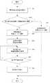
次に、蓄電池制御システム2の動作を説明する。図3は、蓄電池制御システム2のシーケンスを示す図である。 Next, the operation of the storage
エネルギー管理部10は電力調整要求に基づき調整電力量Ptを算出すると、これを調整電力情報として管理ユニット20の決定部23に送信する。The
決定部23は、調整電力情報を受信すると、各蓄電ユニット30に状態通知要求を、通信部21を介して送信する。 Upon receiving the adjusted power information, the
各蓄電ユニット30のBMU34は、状態通知要求を受信すると、状態検出部35から蓄電池情報を取得して決定部23に出力する。 When the
決定部23は、蓄電池情報を受信すると、各蓄電ユニット30に対する電力配分量Pkを決定し、制御部24に電力配分量情報として出力する。Upon receiving the storage battery information, the
制御部24は、電力配分量情報から動作指令を作成して、各蓄電ユニット30のBMU34に出力する。BMU34は、受信した動作指令に基づきインバータ33を制御することにより蓄電池32の充放電を行う。このとき、動作指令に含まれる電力配分量Pkが正値(Pk>0)の場合には蓄電池32の放電が行われ、負値(Pk<0)の場合には蓄電池32に充電が行われる。The
次に、決定部23における蓄電ユニット30に対する電力配分量の決定手順を説明する。図4は、この電力配分量の決定手順を示すフローチャートである。 Next, the procedure for determining the amount of power to be distributed to the
ステップSA1: 決定部23の蓄電容量算出器23aは、状態検出部35で検出された蓄電池情報から現在の蓄電容量(以下、現在蓄電容量と記載する)を算出する。この現在蓄電容量は、全ての蓄電池32に対して算出される。 Step SA1: The
なお、蓄電池32に蓄電されている蓄電容量は、端子電圧から算出される。しかし、端子電圧から算出された蓄電容量は、当該蓄電池32の温度の影響を受けているため、正確な値からずれることがある。そこで、蓄電容量算出器23aは、蓄電池情報に含まれる蓄電池32の温度を用いて端子電圧を補正する。そして、補正された端子電圧を用いて現在蓄電容量を算出する。従って、正確な現在蓄電容量が算出できる。 The storage capacity stored in the
目標蓄電容量設定器23cは、各蓄電池32に対して設定されている目標蓄電容量を記憶部22から読み出す。 The target storage
容量劣化速度算出器23bは、現在蓄電容量及び目標蓄電容量に対する容量劣化速度を、記憶部22に記憶されている容量劣化速度相関情報に基づき算出する。そして、現在蓄電容量における容量劣化速度を現在容量劣化速度、目標蓄電容量における容量劣化速度を目標容量劣化速度とする。 The capacity
ステップSA2〜SA4: 蓄電池32を運転すると、現在蓄電容量に応じて容量劣化速度が大きくなる場合と小さくなる場合がある。図5は、現在蓄電容量から所定の電力を放電した場合の容量劣化速度を例示した図である。 Steps SA2 to SA4: When the
現在蓄電容量が、SOC0_A,SOC0_Bである2つの蓄電池A、Bを想定する。このとき、蓄電池Aは、現在蓄電容量SOC0_Aから目標蓄電容量SOC1_Aに変わる。この場合の容量劣化速度の変化は、式3の制御対象選択条件及び式4の容量劣化量抑制条件を満たす。It is assumed that two storage batteries A and B currently have storage capacities of SOC0 _A and SOC0 _B. At this time, the storage battery A changes from the current storage capacity SOC0 _A to the target storage capacity SOC1 _A. The change in the capacity deterioration rate in this case satisfies the control target selection condition of the formula 3 and the capacity deterioration amount suppression condition of the formula 4.
一方、蓄電池Bは、現在蓄電容量SOC0_Bから目標蓄電容量SOC1_Bに変わる。この場合は、容量劣化速度は大きくなる方向である。従って、この場合の蓄電容量の変化は、式3の制御対象選択条件を満たさないので、式4の容量劣化量抑制条件も満たさない。
On the other hand, the storage battery B changes from the current storage capacity SOC0 _B to the target storage capacity SOC1 _B. In this case, the capacity deterioration rate tends toincrease . Therefore, the change in the storage capacity in this case does not satisfy the control target selection condition of the formula 3, and therefore does not satisfy the capacity deterioration amount suppression condition of the formula 4.
そこで、電力分配器23dは、各蓄電池32に対して、現在容量劣化速度v(SOC0)と目標容量劣化速度v(SOC1)との比較を行う。このとき、現在容量劣化速度v(SOC0)より目標容量劣化速度v(SOC1)が小さい[v(SOC0)≧v(SOC1)]場合は、この蓄電ユニット30を制御対象に選択する。換言すれば、現在容量劣化速度v(SOC0)より目標容量劣化速度v(SOC1)が大きい[v(SOC0)<v(SOC1)]場合は、この蓄電ユニット30は制御対象から除外される。各蓄電ユニット30に対しては、制御対象として選択されたか否かの通知がなされる。Therefore, the
なお、制御対象とした蓄電ユニット30だけでは要求された調整電力量Ptを満たすことができない場合もあり得る。このような場合には、制御対象から除外した蓄電ユニット30の中から容量劣化速度の小さい蓄電ユニットを制御対象に復活させてもよい。Incidentally, only the electric
ステップSA5: このようにして制御対象が選択されると、電力分配器23dは、制御対象に選択された蓄電ユニット30に対して制御の優先順位付けを行う。 Step SA5: When the control target is selected in this way, the
優先順位は、容量劣化量が最小化するように式4の容量劣化量抑制条件を満足し、かつ、目標容量劣化速度の小さい順に高い優先度にする。 The priority is set in descending order of the target capacity deterioration rate while satisfying the capacity deterioration amount suppressing condition of the formula 4 so as to minimize the capacity deterioration amount.
また、優先順位の他の決定方法として、電力調整のインセンティブが最小化するように配分してもよい。電力系統4運用者の立場であれば、インセンティブの支払い額の低い蓄電池制御システム2から優先順位をつけることで運用費を最小化することができる。さらに、原理的に容量劣化による蓄電池32の価値損失とインセンティブとの差額を予測できるので、制御対象が不足する場合はインセンティブを上げて蓄電池制御システム2の保有者に電力調整への参加を促すことができる。 Alternatively, as another method of determining the priority, the incentive for power adjustment may be minimized. From the standpoint of the power system 4 operator, the operating cost can be minimized by prioritizing the storage
ステップSA6〜SA7: 電力分配器23dは、必要な電力量(調整電力量Pt)になるように蓄電ユニット30に対する電力配分量を設定する。設定が行われた場合には、次の蓄電ユニット30に対する電力配分量を設定すべくステップSA6に戻る。なお、決定した電力配分量は電力配分量情報として制御部24に出力される。Step SA6~SA7:
ステップSA8: 制御部24は、電力配分量情報を動作指令として各蓄電ユニット30に出力する。従って、各蓄電ユニット30は、動作指令に従い動作するようになる。 Step SA8: The
以上説明したように、電力調整要求に応じながら蓄電池32の容量劣化を抑制できるようになる。従って、蓄電池32を製品寿命に関する要求を満足させて、電力調整用の分散電源として利用できるようになる。 As described above, the capacity deterioration of the
また、上述した蓄電池制御方法は、電力系統からの要求に対して、充放電の単一動作毎に適用できるので、例えば電力系統での電圧変動抑制や無効電力制御時に大きな効果が得られる。 Further, since the above-mentioned storage battery control method can be applied to each single charge / discharge operation in response to a request from the power system, a great effect can be obtained, for example, when suppressing voltage fluctuations in the power system or controlling reactive power.
<第3実施形態>
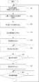
次に、第3実施形態を説明する。なお、第2実施形態と同一構成に関しては、同一符号を用い説明を適宜省略する。本実施形態においては、電力調整を比較的短い一定周期(充放電周期)で行う場合の蓄電池制御方法に関する。図6は、電力配分量の決定手順を示すフローチャートである。<Third Embodiment>
Next, the third embodiment will be described. Regarding the same configuration as that of the second embodiment, the same reference numerals are used and the description thereof will be omitted as appropriate. The present embodiment relates to a storage battery control method in the case where power adjustment is performed in a relatively short constant cycle (charge / discharge cycle). FIG. 6 is a flowchart showing a procedure for determining the power distribution amount.
ステップSB1: 先ず、決定部23の蓄電容量算出器23aは、配下の蓄電ユニット30に対して蓄電池情報を要求し、この蓄電池情報に基づき現在蓄電容量を算出する。 Step SB1: First, the
そして、容量劣化速度算出器23bは、算出された現在蓄電容量を容量劣化速度相関情報に適用して、現在蓄電容量に対する現在容量劣化速度を求める。 Then, the capacity
ステップSB2〜SB4: 次に、目標蓄電容量設定器23cは、要求された周期(充放電周期)で運転した場合の上限蓄電容量と下限蓄電容量とを上限目標蓄電容量、下限目標蓄電容量に設定する。蓄電池32を一定の電力幅で周期運転する場合は、蓄電容量は一定の幅で変化する。このとき充電完了時の蓄電容量が上限目標蓄電容量であり、放電完了時の蓄電容量が下限目標蓄電容量である。 Steps SB2 to SB4: Next, the target storage
そして、容量劣化速度算出器23bは、上限目標蓄電容量に対応する上限容量劣化速度と下限目標蓄電容量に対応する下限容量劣化速度を算出、平均値(平均容量劣化速度)の算出を経て劣化速度差分の算出を行う。 Then, the capacity
上限及び下限容量劣化速度は、容量劣化速度相関情報に上限及び下限目標蓄電容量を適用して算出される。 The upper and lower limit capacity deterioration rates are calculated by applying the upper and lower limit target storage capacities to the capacity deterioration rate correlation information.
平均容量劣化速度vaverageは、上限容量劣化速度と下限容量劣化速度との中心値(中間値)をx1、蓄電容量の変動幅をΔxとすると、
劣化速度差分は、現在蓄電容量での容量劣化速度と平均容量劣化速度との差分である。この劣化速度差分は、
このとき、導関数は
即ち、(x1−Δx,0)、(x1−Δx,v(x1−Δx))、(x1+Δx,0)、(x1+Δx,v(x1+Δx))の4点からなる台形の面積と、x軸、x=x1−Δx、x=x1+Δxと、v(x)とで囲まれる部分の面積を比較すれば良い。具体的には、以下の3つのパターンに分類できる。
(1)容量劣化の蓄電容量依存性が、充放電周期運転の中心値に対して対称な場合
この場合は、平均容量劣化速度vaverageの導関数は0となり、一定値V(x1)をとる。
(2)容量劣化の蓄電容量依存性が下に凸な場合
この場合は、平均容量劣化速度vaverageの導関数は正になる。従って、平均容量劣化速度vaverageは単調増加し、蓄電容量変動幅が大きい程、容量劣化量は増加する。
(3)容量劣化の蓄電容量依存性が上に凸な場合
この場合は、平均容量劣化速度vaverageの導関数は負になる。従って、平均容量劣化速度vaverageは単調減少し、蓄電容量変動幅が大きい程、容量劣化量は少なくなる。That, (x 1 -Δx, 0) , (x 1 -Δx, v (x 1 -Δx)), (x 1 + Δx, 0), the four points(x 1 + Δx, v ( x 1 + Δx)) It is sufficient to compare the area of the trapezoid with the area surrounded by the x-axis, x = x1 − Δx, x = x1 + Δx, and v (x). Specifically, it can be classified into the following three patterns.
(1) When the storage capacity dependence of capacity deterioration is symmetric with respect to the central value of charge / discharge cycle operation In this case, the derivative of the average capacity deterioration rate vaverage becomes 0, and a constant value V (x1 ) is set. Take.
(2) When the storage capacity dependence of capacity deterioration is convex downward In this case, the derivative of the average capacity deterioration rate vaverage becomes positive. Therefore, the average capacity deterioration rate vaverage increases monotonically, and the larger the storage capacity fluctuation range, the larger the capacity deterioration amount.
(3) When the storage capacity dependence of capacity deterioration is convex upward In this case, the derivative of the average capacity deterioration rate vaverage becomes negative. Therefore, the average capacity deterioration rate vaverage decreases monotonically, and the larger the storage capacity fluctuation range, the smaller the capacity deterioration amount.
図7A,7Bは、現在蓄電容量が異なる2つの蓄電ユニット30の容量劣化速度相関情報を示した図で、図7Aは劣化速度差分が小さい場合、図7Bは劣化速度差分が大きい場合の図である。図7Bに示す蓄電ユニット30の劣化速度差分が大きいので、この蓄電ユニット30から優先的に電力配分することになる。結果として均一に配分するよりも、運用時の容量劣化量を少なくすることが可能となる。 7A and 7B are diagrams showing the capacity deterioration rate correlation information of two
ステップSB5〜SB7: そして、電力分配器23dは、劣化速度差分が最も大きい蓄電池から高い優先順位を設定して、ステップSB6にて電力配分量を設定する。このとき各蓄電池に対しての設定値が未定なので、ステップSB7において、各目標蓄電容量の総和が調整電力量Ptに一致するように電力配分量を試算する。試算が行われると、ステップSB6に戻り蓄電池を選択して電力配分量を設定する。Steps SB5 to SB7: Then, the
ステップSB8,SB9: 決定した電力配分量は各蓄電ユニット30に動作指令として出力され、所定時間経過するとステップSB1に戻る。 Steps SB8 and SB9: The determined power distribution amount is output to each
以上説明したように、電力調整に応じながら蓄電池の容量劣化を抑制できるようになる。従って、蓄電池32を製品寿命に関する要求を満足させて、電力調整用の分散電源として利用できるようになる。 As described above, deterioration of the capacity of the storage battery can be suppressed while adjusting the power. Therefore, the
また、上述した蓄電池制御方法は、充放電周期が数秒から数十分程度毎に設定する場合に適しており、例えば電力系統側で規定値より周波数がずれたために周波数調整する際に大きな効果が得られる。 Further, the above-mentioned storage battery control method is suitable when the charge / discharge cycle is set every several seconds to several tens of minutes, and for example, the frequency is deviated from the specified value on the power system side, so that a great effect is obtained when adjusting the frequency. can get.
<第4実施形態>
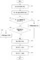
次に、第4実施形態を説明する。なお、第2実施形態と同一構成に関しては、同一符号を用い説明を適宜省略する。上述した各実施形態においては、目標蓄電容量は1つの値であった。これに対して、本実施形態では、複数の目標蓄電容量を設定して蓄電池制御を行う。図8は、各蓄電ユニット30に対して第1目標蓄電容量と第2目標蓄電容量との2つを設定して制御する際のフローチャートである。<Fourth Embodiment>
Next, the fourth embodiment will be described. Regarding the same configuration as that of the second embodiment, the same reference numerals are used and the description thereof will be omitted as appropriate. In each of the above-described embodiments, the target storage capacity was one value. On the other hand, in the present embodiment, a plurality of target storage capacities are set to control the storage battery. FIG. 8 is a flowchart when two target storage capacities and a second target storage capacity are set and controlled for each
ステップSC1,SC2: 決定部23の蓄電容量算出器23aは、蓄電池情報に基づき現在蓄電容量SOC0を算出する。Steps SC1 and SC2: The
そして、目標蓄電容量設定器23cは、容量劣化速度相関情報に基づいて、容量劣化速度が抑制されるような蓄電容量を第1目標蓄電容量SOC1とする。さらに、この第1目標蓄電容量SOC1に到達後の目標蓄電容量を第2目標蓄電容量SOC2として求める。Then, the target storage
第1目標蓄電容量SOC1は、後述する式11の関係に基づき設定される。即ち、式11は式4と同様に容量劣化量抑制条件である。The first target storage capacity SOC1 is set based on the relationship of the formula 11 described later. That is, the formula 11 is a condition for suppressing the amount of capacity deterioration as in the formula 4.
また、第2目標蓄電容量SOC2は、蓄電池を初期状態(運転開始時の状態)に戻すことを目的として設定される目標蓄電容量であり、初期状態に近づく方向に設定する。The second target storage capacity SOC2 is a target storage capacity set for the purpose of returning the storage battery to the initial state (state at the start of operation), and is set in a direction approaching the initial state.
蓄電ユニット30kにおける蓄電池32の初期の蓄電容量SOC0、第1目標蓄電容量SOCk1、第2目標蓄電容量SOC2を、それぞれSOCk0、SOCk1、SOCk2とする。このとき、第2目標蓄電容量SOCk2は、
第1目標蓄電容量SOC1としては、例えば、初期の蓄電容量SOC0に最も近い極小値を設定できる。広義には、初期の蓄電容量SOC0から第1目標蓄電容量SOC1までの範囲において、容量劣化速度における一次微分の符号が変化しない範囲において、この一次微分の絶対値が最小となる点を第1目標蓄電容量SOC1に設定する。このことは、図7Aの蓄電ユニット30又は図7Bの蓄電ユニット30の何れでも利用できることを意味する。As the first target storage capacity SOC1 , for example, the minimum value closest to the initial storage capacity SOC0 can be set. In a broad sense, the point where the absolute value of the first derivative is the smallest in the range from the initial storage capacity SOC0 to the first target storage capacity SOC1 and in the range where the sign of the first derivative in the capacity deterioration rate does not change is the first. 1 Set the target storage capacity SOC1 . This means that either the
このとき、かならずしも極小値のような特定の蓄電容量を目標蓄電容量として定める必要はなく、初期の蓄電容量SOC0に応じて異なる第1目標蓄電容量SOC1を設定するようにしてもよい。例えば、初期の蓄電容量SOC0から所定の蓄電容量変動幅Δだけずれた蓄電容量を目標蓄電量としてもよい。At this time, it is not always necessary to set a specific storage capacity such as a minimum value as the target storage capacity, and a different first target storage capacity SOC1 may be set according to the initial storage capacity SOC0 . For example, the storage capacity deviated from the initial storage capacity SOC0 by a predetermined storage capacity fluctuation width Δ may be set as the target storage capacity.
第2目標蓄電容量SOC2は、例えば初期の蓄電容量SOC0とすることができる。なお、第2目標蓄電容量SOC2は容量劣化抑制の観点から初期の蓄電容量SOC0以下であることが望ましいが、必ずしもそれに限定されるものではない。ここでは説明を単純化するため、第2目標蓄電容量SOC2≦初期の蓄電容量SOC0であるとした。The second target storage capacity SOC2 can be, for example, the initial storage capacity SOC0 . The second target storage capacity SOC2 is preferably, but is not necessarily limited to, the initial storage capacity SOC0 or less from the viewpoint of suppressing capacity deterioration. Here, in order to simplify the explanation, it is assumed that the second target storage capacity SOC2 ≤ the initial storage capacity SOC0 .
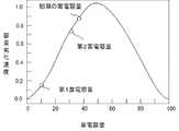
このような目標蓄電容量に基づく充放電を行う過程において、蓄電池32の容量劣化速度には、
図9A,9Bは、決定した目標蓄電容量を例示した図で、図9Aは蓄電容量が少なくなるに従い容量劣化速度が小さくなる場合、図9Bは蓄電容量が少なくなるに従い容量劣化速度が大きくなる場合を示した図である。 9A and 9B are diagrams exemplifying the determined target storage capacity, FIG. 9A shows a case where the capacity deterioration rate decreases as the storage capacity decreases, and FIG. 9B shows a case where the capacity deterioration rate increases as the storage capacity decreases. It is a figure which showed.
ステップSC3〜SC6: 目標蓄電容量設定器23cは、決定した目標蓄電容量(第1目標蓄電容量、第2目標蓄電容量)を設定するか否かの判断、及び、更新するか否かの判断を行い、設定する場合にはステップSC4において設定され、更新する場合にはステップSC6において更新される。 Steps SC3 to SC6: The target storage
ステップSC7〜SC9: 続いて、電力分配器23dは、各蓄電ユニット30への充放電電力の配分を式5〜7が成立するように決定する。例えば、容量劣化速度の大きい状態にある蓄電池32を素早く容量劣化速度の小さい状態に移行し、容量劣化速度の小さい状態に長くとどまるように電力配分制御することが考えられる。 Steps SC7 to SC9: Subsequently, the
この場合には、重み付け量は、例えば現在蓄電容量における容量劣化速度が大きい程電力配分量が大きく、容量劣化速度が小さい程電力配分量が小さくすれば良く、現在蓄電容量の容量劣化速度の大きさで比例配分することが一例として考えられる。 In this case, the weighting amount may be, for example, the larger the capacity deterioration rate in the current storage capacity, the larger the power distribution amount, and the smaller the capacity deterioration rate, the smaller the power distribution amount, and the larger the capacity deterioration rate of the current storage capacity. Proportional distribution can be considered as an example.
また、例えば調整電力量に応じた充放電による蓄電容量変化の方向が目標蓄電容量へ向かう方向と逆方向の場合には電力を配分しないことができる。 Further, for example, when the direction of the storage capacity change due to charging / discharging according to the adjusted power amount is opposite to the direction toward the target storage capacity, the power cannot be distributed.
より具体的には、蓄電ユニット30kへの配分の重み係数akは、
このような重み付けを行うことで、容量劣化速度の大きい状態にあるものの配分電力が多くなり、素早く容量劣化速度の少ない状態に移行する。また、容量劣化速度が少ない状態にある蓄電池32への配分電力が相対的に小さくなり、その状態に長くとどまることができる。 By performing such weighting, although the capacity deterioration rate is high, the distributed power increases, and the state quickly shifts to the state where the capacity deterioration rate is low. Further, the distributed power to the
なお、上記の例では、説明を簡単にするために重み係数akは容量劣化速度の大きさに比例するとした。しかし、実際は容量劣化速度の速さの一次関数に限らず、容量劣化速度Vkと現在の蓄電容量SOCk、目標蓄電容量SOCiと目標蓄電容量の状態iを変数としたbベキ関数や指数関数等の数学的な関数であってもよい。また、数学的関数に限らず、入力変数に対して重み付けが決まる関数的な対応関係であればよい。In the above example, the weighting coefficientak is proportional to the magnitude of the capacity deterioration rate for the sake of simplicity. However, in reality, it is not limited to the linear function of the capacity deterioration rate, but the b-power function or index with the capacity deterioration rate Vk and the current storage capacity SOCk , the target storage capacity SOCi and the target storage capacity state i as variables. It may be a mathematical function such as a function. Further, it is not limited to a mathematical function, and may be a functional correspondence in which weighting is determined for an input variable.
入力変数に対して重み付けが決まる対応関係は、容量劣化速度をもとに予め決定された現在の蓄電容量と目標蓄電容量と電力配分量の重み付け量の対応関係を示す表のようなものでもよい。 The correspondence relationship in which the weight is determined for the input variable may be something like a table showing the correspondence relationship between the current storage capacity, the target storage capacity, and the weighting amount of the power distribution amount, which is determined in advance based on the capacity deterioration rate. ..
上述したいずれの蓄電容量においても同様に配分を行うことになるが、特定の蓄電容量条件においては充放電を配分しないこともできる。例えば、初期の蓄電容量と目標蓄電容量との差が設定された閾値よりも小さい場合は充放電を配分しないこともできる。これは、例えば、初期の蓄電容量が極小値近傍に存在する場合の充放電による蓄電容量変化により容量劣化が加速される可能性を排除する効果が期待できる。なお、この閾値は固定値に限るものではなく、蓄電容量、充放電履歴、容量劣化の進行状況に応じて可変であってもよい。 Allocation is performed in the same manner for any of the above-mentioned storage capacities, but charge / discharge may not be allocated under specific storage capacity conditions. For example, if the difference between the initial storage capacity and the target storage capacity is smaller than the set threshold value, the charge / discharge may not be distributed. This can be expected to have the effect of eliminating the possibility that the capacity deterioration is accelerated due to the change in the storage capacity due to charging / discharging when the initial storage capacity exists in the vicinity of the minimum value, for example. The threshold value is not limited to a fixed value, and may be variable depending on the storage capacity, charge / discharge history, and progress of capacity deterioration.
以上説明したように、電力調整に応じながら蓄電池32の容量劣化を抑制できるようになる。従って、蓄電池32を製品寿命に関する要求を満足させて、電力調整用の分散電源として利用できるようになる。 As described above, the capacity deterioration of the
<実施例1>
次に、正極にマンガンスピネル、負極に炭素材料を用いたリチウムイオン電池セルからなる蓄電池32に対して、上述した制御方法を適用した場合の実施例を説明する。<Example 1>
Next, an example will be described when the above-mentioned control method is applied to a
この実施例では、33Ahの単セルからなる蓄電池32、BMU、他の構成要素をパーソナルコンピュータで構成した。また、蓄電池32の電力調整前の初期の蓄電容量が20%、50%、70%の蓄電ユニットA〜蓄電ユニットCであり、電力系統4からの電力調整要求が60Wの電力消費削減(電力系統4の負荷を削減する意味であり、このことは蓄電池32の放電を意味する)を20分間動作させるとした。 In this embodiment, a
このような条件で、各蓄電ユニット30における蓄電池32の現在の蓄電容量を算出した。次に、容量劣化速度相関関係を用いて、現在の蓄電容量と電力消費を削減(蓄電池32を放電)する方向の蓄電容量との劣化速度差分を算出した。下記の表1は、この結果を示している。
(表1)
(Table 1)
表1から容量劣化速度が現在値よりも低減(変化量がマイナス符号)するのは、蓄電ユニットAの蓄電容量20%の場合と蓄電ユニットBの蓄電容量50%の場合であることがわかる。そこで、蓄電ユニットCは制御対象から除外し、蓄電ユニットA,Bを制御の対象とした。 From Table 1, it can be seen that the capacity deterioration rate is lower than the current value (the amount of change is a minus sign) when the storage capacity of the power storage unit A is 20% and when the storage capacity of the power storage unit B is 50%. Therefore, the power storage unit C is excluded from the control target, and the power storage units A and B are controlled.
そして、蓄電ユニット30Aより容量劣化速度の絶対値が大きい蓄電ユニット30Bを高い優先度に設定した。このとき、蓄電ユニット30Bに対して電力50Wで20分間放電するように目標蓄電容量を設定した。さらに残りの必要な電力量である10Wを蓄電ユニット30Aに配分した。 Then, the power storage unit 30B having a larger absolute value of the capacity deterioration rate than the power storage unit 30A was set to a higher priority. At this time, the target storage capacity was set so as to discharge the power storage unit 30B at 50 W for 20 minutes. Further, the remaining required electric energy of 10 W was allocated to the power storage unit 30A.
比較例として、全ての蓄電ユニット30を均等に40Wで20分間放電するように目標蓄電容量を設定して動作を行った。 As a comparative example, the target storage capacity was set and the operation was performed so that all the
実施例1と比較例とで同じ動作を1週間繰り返した後の(1カ月の運用を想定)、3つのセルの容量劣化量を比較したところ、実施例1の方が初期の蓄電容量に対して0.6%の改善が認められた。さらに、長期運用時の容量劣化量を単純な積み上げ式の計算から推定すると、年間で6%、5年間で30%の容量劣化抑制効果が得られることがわかった。 When the capacity deterioration amounts of the three cells were compared after repeating the same operation for one week in Example 1 and Comparative Example (assuming one-month operation), Example 1 had a higher storage capacity than the initial storage capacity. An improvement of 0.6% was observed. Furthermore, when the amount of capacity deterioration during long-term operation is estimated from a simple stacking formula calculation, it was found that a capacity deterioration suppressing effect of 6% per year and 30% per year can be obtained.
これにより、本実施形態にかかる蓄電池制御システム2では、寿命容量劣化を抑制しながら電力調整が実現できることが示された。 As a result, it was shown that the storage
<実施例2>
次に、実施例1で用いたのと同じ仕様の蓄電池制御システム2の構成において、一定の周期で電力量を調整する場合の効果を検証した。このとき、電力系統4からの電力調整要求が90Wを20分間周期的に充放電させる内容であるとした。<Example 2>
Next, in the configuration of the storage
このような条件で、各蓄電ユニットにおける蓄電池32の現在の蓄電容量を算出した。次に、パーソナルコンピュータに予め記憶している容量劣化速度の相関関係を用いて、現在の蓄電容量での容量劣化速度と上下10%の蓄電容量の容量劣化速度の平均値の劣化速度差分を比較した。下記の表2は、この比較結果を示している。
(表2)
(Table 2)
表2に示すように、劣化速度差分は、蓄電ユニット30A<蓄電ユニット30C<蓄電ユニット30Bの順番となった。これから蓄電ユニット30Aと蓄電ユニット30Cで電力配分することとした。ここでは制御しやすいように各セルへの電力割り当ては均等にして、目標蓄電容量を設定した。 As shown in Table 2, the deterioration rate difference was in the order of power storage unit 30A <power storage unit 30C <power storage unit 30B. From now on, it is decided to distribute power between the power storage unit 30A and the power storage unit 30C. Here, the target storage capacity was set by equalizing the power allocation to each cell for easy control.
また、比較例として、全ての蓄電ユニット30を均等に30Wで20分間周期的に充放電を行うように目標蓄電容量を設定した場合も調べた。 Further, as a comparative example, a case where the target storage capacity was set so that all the
実施例2と比較例とで同じ動作を1週間繰り返した後の、3つの蓄電ユニット30における蓄電池32の容量劣化量を比較したところ、実施例2の方が初期の蓄電容量に対して0.2%の改善が認められた。 When the capacity deterioration amount of the
なお、平均値の劣化速度差分が最も大きかった蓄電ユニット30Bと蓄電ユニット30A,蓄電ユニット30Bと蓄電ユニット30Cとを組み合わせた場合には、比較例よりも容量劣化が高い結果となった。 When the power storage unit 30B and the power storage unit 30A and the power storage unit 30B and the power storage unit 30C, which had the largest difference in the deterioration rate of the average values, were combined, the result was that the capacity deterioration was higher than in the comparative example.
これにより、本実施形態にかかる蓄電池制御システムでは、単純な積み上げ式の計算によると、年間での容量劣化は2.4%、5年間の運用で12%の寿命容量劣化に対する抑制効果が得られることがわかった。 As a result, in the storage battery control system according to the present embodiment, according to a simple stacking type calculation, the annual capacity deterioration is 2.4%, and the life capacity deterioration can be suppressed by 12% after 5 years of operation. I understand.
これにより、本実施形態にかかる蓄電池制御システムでは、寿命容量劣化を抑制しながら電力調整が実現できることが示された。 As a result, it was shown that the storage battery control system according to the present embodiment can realize power adjustment while suppressing deterioration of life capacity.
なお、上述した蓄電池制御方法をプログラム化してコンピュータに読み取り可能に情報記録媒体に記録することが可能である。 It is possible to program the above-mentioned storage battery control method and record it on an information recording medium so that it can be read by a computer.
以上、実施形態(及び実施例)を参照して本願発明を説明したが、本願発明は上記実施形態(及び実施例)に限定されるものではない。本願発明の構成や詳細には、本願発明のスコープ内で当業者が理解し得る様々な変更をすることができる。Although the invention of the present application has been described above with reference to the embodiments (and examples), the invention of the present application is not limited to the above-described embodiments (and examples). Various changes that can be understood by those skilled in the art can be made within the scope of the present invention in terms of the structure and details of the present invention.
この出願は、2015年1月15日に出願された日本出願特願2015−005741を基礎とする優先権を主張し、その開示の全てをここに取り込む。 This application claims priority on the basis of Japanese application Japanese Patent Application No. 2015-005741 filed on January 15, 2015, the entire disclosure of which is incorporated herein by reference.
2 蓄電池制御システム
4 電力系統
8 送電線
10 エネルギー管理部(EMU)
20 管理ユニット
20 蓄電容量
21 通信部
22 記憶部
23 決定部
23a 蓄電容量算出器
23b 容量劣化速度算出器
23c 目標蓄電容量設定器
23d 電力分配器
24 制御部
30(30a〜30n) 蓄電ユニット
31 通信部
32 蓄電池
33 インバータ
34 電池管理部(BMU)
35 状態検出部2 Storage battery control system 4
20
35 State detector
Claims (10)
Translated fromJapanese前記蓄電池の蓄電池情報に基づき該蓄電池の現在蓄電容量を算出する蓄電容量算出手段と、
前記蓄電池の運転を停止する際の目標蓄電容量を設定する目標蓄電容量設定手段と、
予め設定された容量劣化速度相関情報に前記現在蓄電容量及び前記目標蓄電容量を適用して、各蓄電容量に対する現在容量劣化速度及び目標容量劣化速度を算出する容量劣化速度算出手段と、
運転開始時からの経過時間をt、容量劣化速度が蓄電容量に応じて変動する場合の当該容量劣化速度の時間積分値を容量劣化量DSOC変動(t)、容量劣化速度が蓄電容量にかかわらず、前記現在蓄電容量での容量劣化速度のまま一定とした場合の当該容量劣化速度の時間積分値を容量劣化量DSOC一定(t)とした際に、容量劣化量DSOC変動(t)≦容量劣化量DSOC一定(t)の容量劣化量抑制条件を満たすように複数の前記蓄電池に電力を配分する電力配分手段と、
を備えることを特徴とする蓄電池制御システム。It is a storage battery control system that performs charge / discharge control for multiple storage batteries under its control based on the power adjustment request from the power system.
A power storage capacity calculating means for calculating acurrent charge reservoir capacity of storage battery based on the battery information of the battery,
A target storage capacity setting means for setting a target storage capacity when the operation of the storage battery is stopped, and a target storage capacity setting means.
A capacity deterioration rate calculation means for calculating the current capacity deterioration rate and the target capacity deterioration rate for each storage capacity by applying the current storage capacity and the target storage capacity to the preset capacity deterioration rate correlation information.
The elapsed time from the start of operation is t, the time integral value of the capacity deterioration rate when the capacity deterioration rate fluctuates according to the storage capacity is the capacity deterioration amount DSOC fluctuation (t), and the capacity deterioration rate is regardless of the storage capacity. When the time integral value of the capacity deterioration rate is kept constant at the current storage capacity and the capacity deterioration amount DSOC is constant (t), the capacity deterioration amount DSOC fluctuation (t) ≤ capacity deterioration A powerdistribution means for allocating power to a plurality of the storage batteries so as to satisfy the condition of suppressing the amount of capacity deterioration having a constant amount of DSOC (t), and
A storage battery control system characterized by being equipped with.
前記電力配分手段は、前記目標容量劣化速度が小さい順から電力の配分を行うことを特徴とする蓄電池制御システム。In the storage battery control system according to claim 1,
The power distribution means is a storage battery control system characterized in that power is distributed in ascending order of the target capacity deterioration rate.
前記電力配分手段は、前記蓄電池の充電と放電とを繰り返して上限蓄電容量と下限蓄電容量との間で周期運転が行われる際に、前記上限蓄電容量と前記下限蓄電容量とに対応した上限容量劣化速度と下限容量劣化速度との平均値である平均容量劣化速度よりも小さい容量劣化速度の蓄電池から電力配分することを特徴とする蓄電池制御システム。In the storage battery control system according to claim 1,
The power distribution means has an upper limit capacity corresponding to the upper limit storage capacity and the lower limit storage capacity when a periodic operation is performed between the upper limit storage capacity and the lower limit storage capacity by repeating charging and discharging of the storage battery. A storage battery control system characterized in that power is distributed from a storage battery having a capacity deterioration rate smaller than the average capacity deterioration rate, which is the average value of the deterioration rate and the lower limit capacity deterioration rate.
前記電力配分手段は、前記蓄電池の現在の前記蓄電容量と、該蓄電容量における前記容量劣化速度とを変数とする重み関数により与えられる重み係数を、前記電力系統から要求された電力調整量に規格化して重み付けすることにより電力配分することを特徴とする蓄電池制御システム。In the storage battery control system according to claim 1,
The power distribution means standardizes a weighting coefficient given by a weighting function having the current storage capacity of the storage battery and the capacity deterioration rate in the storage capacity as variables, as a power adjustment amount requested by the power system. A storage battery control system characterized in that power is distributed by converting and weighting.
前記目標蓄電容量設定手段は、前記目標蓄電容量が、前記容量劣化量抑制条件を満たす第1目標蓄電容量と、該第1目標蓄電容量に到達後の目標蓄電容量である第2目標蓄電容量とを設定し、かつ、前記第2目標蓄電容量は運転開始時の前記容量劣化速度より小さいと共に、前記第1目標蓄電容量の前記容量劣化速度より大きいことを特徴とする蓄電池制御システム。In the storage battery control system according to any one of claims 1 to 4.
The target storage capacity setting means includes a first target storage capacity in which the target storage capacity satisfies the capacity deterioration suppression amount condition, and a second target storage capacity which is a target storage capacity after reaching the first target storage capacity. The storage battery control system is characterized in that the second target storage capacity is smaller than the capacity deterioration rate at the start of operation and is larger than the capacity deterioration rate of the first target storage capacity.
前記蓄電池の蓄電池情報に基づき該蓄電池の現在蓄電容量を算出し、
前記蓄電池の運転を停止する際の目標蓄電容量を設定し、
予め設定された容量劣化速度相関情報に前記現在蓄電容量及び前記目標蓄電容量を適用して、各蓄電容量に対する現在容量劣化速度及び目標容量劣化速度を算出し、
運転開始時からの経過時間をt、容量劣化速度が蓄電容量に応じて変動する場合の当該容量劣化速度の時間積分値を容量劣化量DSOC変動(t)、容量劣化速度が蓄電容量にかかわらず、前記現在蓄電容量での容量劣化速度のまま一定とした場合の当該容量劣化速度の時間積分値を容量劣化量DSOC一定(t)とした際に、容量劣化量DSOC変動(t)≦容量劣化量DSOC一定(t)の容量劣化量抑制条件を満たすように複数の前記蓄電池に電力を配分する、
ことを特徴とする蓄電池制御方法。It is a storage battery control method that performs charge / discharge control for a plurality of storage batteries under its control based on a power adjustment request from the power system.
Calculating acurrent charge reservoir capacity of storage battery based on the battery information of the battery,
Set the target storage capacity when stopping the operation of the storage battery,
By applying the current storage capacity and the target storage capacity to the preset capacity deterioration rate correlation information, the current capacity deterioration rate and the target capacity deterioration rate for each storage capacity are calculated.
The elapsed time from the start of operation is t, the time integral value of the capacity deterioration rate when the capacity deterioration rate fluctuates according to the storage capacity is the capacity deterioration amount DSOC fluctuation (t), and the capacity deterioration rate is regardless of the storage capacity. When the time integral value of the capacity deterioration rate is kept constant at the current storage capacity and the capacity deterioration amount DSOC is constant (t), the capacity deterioration amount DSOC fluctuation (t) ≤ capacity deterioration The power is distributed to the plurality of storage batteries so as to satisfy the condition of suppressing the capacity deterioration amount having a constant amount of DSOC (t).
A storage battery control method characterized by this.
前記目標容量劣化速度が小さい順から電力の配分を行うことを特徴とする蓄電池制御方法。In the storage battery control method according to claim6 ,
A storage battery control method characterized in that power is distributed in ascending order of the target capacity deterioration rate.
前記蓄電池の充電と放電とを繰り返して上限蓄電容量と下限蓄電容量との間で周期運転が行われる際に、前記上限蓄電容量と前記下限蓄電容量とに対応した上限容量劣化速度と下限容量劣化速度との平均値である平均容量劣化速度よりも小さい容量劣化速度の蓄電池から電力配分することを特徴とする蓄電池制御方法。In the storage battery control method according to claim6 ,
When periodic operation is performed between the upper limit storage capacity and the lower limit storage capacity by repeating charging and discharging of the storage battery, the upper limit capacity deterioration rate and the lower limit capacity deterioration corresponding to the upper limit storage capacity and the lower limit storage capacity A storage battery control method characterized in that power is distributed from a storage battery having a capacity deterioration rate smaller than the average capacity deterioration rate, which is an average value with the speed.
前記蓄電池の蓄電池情報に基づき該蓄電池の現在蓄電容量を算出するステップと、
前記蓄電池の運転を停止する際の目標蓄電容量を設定するステップと、
予め設定された容量劣化速度相関情報に前記現在蓄電容量及び前記目標蓄電容量を適用して、各蓄電容量に対する現在容量劣化速度及び目標容量劣化速度を算出するステップと、
運転開始時からの経過時間をt、容量劣化速度が蓄電容量に応じて変動する場合の当該容量劣化速度の時間積分値を容量劣化量DSOC変動(t)、容量劣化速度が蓄電容量にかかわらず、前記現在蓄電容量での容量劣化速度のまま一定とした場合の当該容量劣化速度の時間積分値を容量劣化量DSOC一定(t)とした際に、容量劣化量DSOC変動(t)≦容量劣化量DSOC一定(t)の容量劣化量抑制条件を満たすように複数の前記蓄電池に電力を配分するステップと、
を含むことを特徴とする蓄電池制御プログラム。A storage battery control program that causes a computer to perform charge / discharge control for a plurality of storage batteries under its control based on a power adjustment request from the power system.
Calculating acurrent charge reservoir capacity of storage battery based on the battery information of the battery,
A step of setting a target storage capacity when stopping the operation of the storage battery, and
A step of applying the current storage capacity and the target storage capacity to the preset capacity deterioration rate correlation information to calculate the current capacity deterioration rate and the target capacity deterioration rate for each storage capacity.
The elapsed time from the start of operation is t, the time integral value of the capacity deterioration rate when the capacity deterioration rate fluctuates according to the storage capacity is the capacity deterioration amount DSOC fluctuation (t), and the capacity deterioration rate is regardless of the storage capacity. When the time integral value of the capacity deterioration rate is kept constant at the current storage capacity and the capacity deterioration amount DSOC is constant (t), the capacity deterioration amount DSOC fluctuation (t) ≤ capacity deterioration A step of allocating power to a plurality of the storage batteries so as to satisfy the condition of suppressing the capacity deterioration amount of a constant amount DSOC (t), and
A storage battery control program characterized by including.
前記目標容量劣化速度が小さい順から電力の配分を行うステップを含むことを特徴とする請求項9に記載の蓄電池制御プログラム。Et al.Is,
Thestorage battery control program according to claim9 , further comprising a step of allocating electric power in ascending order of the target capacity deterioration rate.
Applications Claiming Priority (3)
| Application Number | Priority Date | Filing Date | Title |
|---|---|---|---|
| JP2015005741 | 2015-01-15 | ||
| JP2015005741 | 2015-01-15 | ||
| PCT/JP2016/000201WO2016114147A1 (en) | 2015-01-15 | 2016-01-15 | Storage cell control system, storage cell control method, and recording medium |
Publications (2)
| Publication Number | Publication Date |
|---|---|
| JPWO2016114147A1 JPWO2016114147A1 (en) | 2017-10-26 |
| JP6790833B2true JP6790833B2 (en) | 2020-11-25 |
Family
ID=56405695
Family Applications (1)
| Application Number | Title | Priority Date | Filing Date |
|---|---|---|---|
| JP2016569294AActiveJP6790833B2 (en) | 2015-01-15 | 2016-01-15 | Storage battery control system, storage battery control method, and recording medium |
Country Status (3)
| Country | Link |
|---|---|
| US (1) | US10403936B2 (en) |
| JP (1) | JP6790833B2 (en) |
| WO (1) | WO2016114147A1 (en) |
Families Citing this family (11)
| Publication number | Priority date | Publication date | Assignee | Title |
|---|---|---|---|---|
| JP7255086B2 (en)* | 2017-04-28 | 2023-04-11 | 富士電機株式会社 | Charge/Discharge Distribution Control Device, Charge/Discharge Distribution Control System, and Charge/Discharge Distribution Control Method |
| JP6997555B2 (en)* | 2017-08-04 | 2022-01-17 | 株式会社東芝 | Information processing equipment, communication systems, information processing methods, and programs |
| DE102018203528A1 (en)* | 2018-03-08 | 2019-09-12 | Siemens Aktiengesellschaft | Method of operating an energy system and energy system |
| JP7072050B2 (en)* | 2018-03-26 | 2022-05-19 | 京セラ株式会社 | Control device, information processing device and storage battery search system |
| EP3817184A4 (en)* | 2018-06-28 | 2022-03-30 | Kyocera Corporation | MANAGEMENT SERVER, MANAGEMENT SYSTEM AND MANAGEMENT METHOD |
| WO2020080284A1 (en) | 2018-10-15 | 2020-04-23 | 京セラ株式会社 | Power management apparatus, power management system, and power management method |
| US11682916B2 (en) | 2020-03-09 | 2023-06-20 | Insurtap Inc. | Processing device, processing method, and non-transitory storage medium |
| JP2021191095A (en)* | 2020-05-29 | 2021-12-13 | 株式会社日立製作所 | Power storage system control device, power storage system, and program |
| US20220043414A1 (en)* | 2020-08-05 | 2022-02-10 | Korea Advanced Institute Of Science And Technology | Apparatus and method for operating energy storage system |
| CN115441018B (en)* | 2021-06-02 | 2024-12-17 | 卡明斯公司 | Method and system for managing and implementing state of health to control fuel cell life |
| JP7652200B2 (en)* | 2023-02-09 | 2025-03-27 | 株式会社豊田中央研究所 | Information processing system, information processing method, and information processing program |
Family Cites Families (16)
| Publication number | Priority date | Publication date | Assignee | Title |
|---|---|---|---|---|
| JP2000030751A (en) | 1998-07-10 | 2000-01-28 | Toyota Central Res & Dev Lab Inc | Charge / discharge method of lithium secondary battery |
| JP2001307781A (en) | 2000-04-24 | 2001-11-02 | Hitachi Ltd | Lithium secondary battery and charge / discharge method thereof |
| US7227335B2 (en)* | 2003-07-22 | 2007-06-05 | Makita Corporation | Method and apparatus for diagnosing the condition of a rechargeable battery |
| JP5044511B2 (en)* | 2008-09-03 | 2012-10-10 | トヨタ自動車株式会社 | Lithium ion battery degradation determination method, lithium ion battery control method, lithium ion battery degradation determination apparatus, lithium ion battery control apparatus, and vehicle |
| JP5789736B2 (en)* | 2009-10-23 | 2015-10-07 | パナソニックIpマネジメント株式会社 | Power supply |
| JP5466564B2 (en)* | 2010-04-12 | 2014-04-09 | 本田技研工業株式会社 | Battery degradation estimation method, battery capacity estimation method, battery capacity equalization method, and battery degradation estimation apparatus |
| CN103329392B (en) | 2011-01-18 | 2016-02-17 | 日产自动车株式会社 | Battery control device |
| WO2012111234A1 (en) | 2011-02-18 | 2012-08-23 | 三洋電機株式会社 | Power supply system |
| JP2013247726A (en)* | 2012-05-24 | 2013-12-09 | Toshiba Corp | Storage battery deterioration controller |
| TWI473323B (en)* | 2012-12-13 | 2015-02-11 | Ind Tech Res Inst | Charging method for charging battery and related charging structure |
| JP6157880B2 (en) | 2013-03-04 | 2017-07-05 | 株式会社東芝 | Secondary battery system having a plurality of batteries and charge / discharge power distribution method |
| CN104037462B (en)* | 2013-03-08 | 2016-04-27 | 华硕电脑股份有限公司 | Battery module and overcharge protection method |
| WO2014147973A1 (en)* | 2013-03-19 | 2014-09-25 | 三洋電機株式会社 | Secondary battery charging system and method, and battery pack |
| US20140320085A1 (en)* | 2013-04-24 | 2014-10-30 | Dynapack International Technology Corporation | Charging device and control method thereof |
| KR20150126208A (en)* | 2014-05-02 | 2015-11-11 | 삼성에스디아이 주식회사 | Battery and battery management apparatus |
| US20160105044A1 (en)* | 2014-10-08 | 2016-04-14 | Panasonic Intellectual Property Management Co., Ltd. | Power-storage-system control method and power-storage-system control apparatus |
- 2016
- 2016-01-15USUS15/542,511patent/US10403936B2/ennot_activeExpired - Fee Related
- 2016-01-15JPJP2016569294Apatent/JP6790833B2/enactiveActive
- 2016-01-15WOPCT/JP2016/000201patent/WO2016114147A1/ennot_activeCeased
Also Published As
| Publication number | Publication date |
|---|---|
| US20180269541A1 (en) | 2018-09-20 |
| JPWO2016114147A1 (en) | 2017-10-26 |
| US10403936B2 (en) | 2019-09-03 |
| WO2016114147A1 (en) | 2016-07-21 |
Similar Documents
| Publication | Publication Date | Title |
|---|---|---|
| JP6790833B2 (en) | Storage battery control system, storage battery control method, and recording medium | |
| CN103311958B (en) | Power supply and demand control device | |
| KR101725701B1 (en) | Secondary cell system having plurality of cells, and method for distributing charge/discharge electric power or current | |
| CN101902049B (en) | Method for operating energy storage system | |
| US10389165B2 (en) | Energy management apparatus, energy management method and program recording medium | |
| JP6427826B2 (en) | Control device, control method and program | |
| US20220161687A1 (en) | Energy system control | |
| JP6062163B2 (en) | Power supply system | |
| JP5113789B2 (en) | Charge / discharge control device and charge / discharge control method | |
| JP6942295B1 (en) | Charge / discharge plan creation device, command device, power system management system, terminal device, power storage system, charge / discharge system, storage battery, electric vehicle, charge / discharge plan creation method and charge / discharge plan creation program | |
| JP2017163835A (en) | Battery control system | |
| US9780565B2 (en) | System and method for controlling frequency | |
| CN101340104B (en) | Method for charging a storage element of an autonomous system | |
| JPWO2016136260A1 (en) | Power management apparatus, power management system, and power management method | |
| US10074986B2 (en) | System for providing a primary control power for a power grid | |
| JP2014236600A (en) | Controller for a plurality of purposes of circuit storage battery | |
| JP2014236602A (en) | Multiple purpose controller, multiple purpose control system and program of multiple storage batteries | |
| WO2023223618A1 (en) | Charge/discharge control device, charge/discharge control method, and program | |
| WO2020241481A1 (en) | Renewable energy power generator command controller and renewable energy power generator system including storage battery | |
| KR20150135843A (en) | Hybrid energy storage system and method of contolling the same | |
| KR102029030B1 (en) | Apparatus and method for controlling drive of energy storage system considering both long term and short term characteristics | |
| JP7746216B2 (en) | Upper-level power management device, power interchange control method, and power interchange control program | |
| JP2023157240A (en) | Power management device, upper power management device, power management method, and power management program | |
| JP2018157647A (en) | Information processing apparatus, control device for power storage apparatus, electric power system, control method, and program | |
| JP6390259B2 (en) | Charge / discharge control device and charge / discharge control method |
Legal Events
| Date | Code | Title | Description |
|---|---|---|---|
| A521 | Request for written amendment filed | Free format text:JAPANESE INTERMEDIATE CODE: A523 Effective date:20170622 | |
| A621 | Written request for application examination | Free format text:JAPANESE INTERMEDIATE CODE: A621 Effective date:20181214 | |
| A131 | Notification of reasons for refusal | Free format text:JAPANESE INTERMEDIATE CODE: A131 Effective date:20200121 | |
| A521 | Request for written amendment filed | Free format text:JAPANESE INTERMEDIATE CODE: A523 Effective date:20200228 | |
| A131 | Notification of reasons for refusal | Free format text:JAPANESE INTERMEDIATE CODE: A131 Effective date:20200714 | |
| A521 | Request for written amendment filed | Free format text:JAPANESE INTERMEDIATE CODE: A523 Effective date:20200722 | |
| TRDD | Decision of grant or rejection written | ||
| A01 | Written decision to grant a patent or to grant a registration (utility model) | Free format text:JAPANESE INTERMEDIATE CODE: A01 Effective date:20201006 | |
| A61 | First payment of annual fees (during grant procedure) | Free format text:JAPANESE INTERMEDIATE CODE: A61 Effective date:20201019 | |
| R150 | Certificate of patent or registration of utility model | Ref document number:6790833 Country of ref document:JP Free format text:JAPANESE INTERMEDIATE CODE: R150 |