JP6786561B2 - Body front structure - Google Patents
Body front structureDownload PDFInfo
- Publication number
- JP6786561B2 JP6786561B2JP2018179734AJP2018179734AJP6786561B2JP 6786561 B2JP6786561 B2JP 6786561B2JP 2018179734 AJP2018179734 AJP 2018179734AJP 2018179734 AJP2018179734 AJP 2018179734AJP 6786561 B2JP6786561 B2JP 6786561B2
- Authority
- JP
- Japan
- Prior art keywords
- face member
- vehicle body
- license plate
- front bumper
- outside air
- Prior art date
- Legal status (The legal status is an assumption and is not a legal conclusion. Google has not performed a legal analysis and makes no representation as to the accuracy of the status listed.)
- Expired - Fee Related
Links
Images


Classifications
- B—PERFORMING OPERATIONS; TRANSPORTING
- B60—VEHICLES IN GENERAL
- B60R—VEHICLES, VEHICLE FITTINGS, OR VEHICLE PARTS, NOT OTHERWISE PROVIDED FOR
- B60R19/00—Wheel guards; Radiator guards, e.g. grilles; Obstruction removers; Fittings damping bouncing force in collisions
- B60R19/02—Bumpers, i.e. impact receiving or absorbing members for protecting vehicles or fending off blows from other vehicles or objects
- B60R19/18—Bumpers, i.e. impact receiving or absorbing members for protecting vehicles or fending off blows from other vehicles or objects characterised by the cross-section; Means within the bumper to absorb impact
- B—PERFORMING OPERATIONS; TRANSPORTING
- B60—VEHICLES IN GENERAL
- B60R—VEHICLES, VEHICLE FITTINGS, OR VEHICLE PARTS, NOT OTHERWISE PROVIDED FOR
- B60R19/00—Wheel guards; Radiator guards, e.g. grilles; Obstruction removers; Fittings damping bouncing force in collisions
- B60R19/02—Bumpers, i.e. impact receiving or absorbing members for protecting vehicles or fending off blows from other vehicles or objects
- B60R19/48—Bumpers, i.e. impact receiving or absorbing members for protecting vehicles or fending off blows from other vehicles or objects combined with, or convertible into, other devices or objects, e.g. bumpers combined with road brushes, bumpers convertible into beds
- B—PERFORMING OPERATIONS; TRANSPORTING
- B60—VEHICLES IN GENERAL
- B60R—VEHICLES, VEHICLE FITTINGS, OR VEHICLE PARTS, NOT OTHERWISE PROVIDED FOR
- B60R19/00—Wheel guards; Radiator guards, e.g. grilles; Obstruction removers; Fittings damping bouncing force in collisions
- B60R19/02—Bumpers, i.e. impact receiving or absorbing members for protecting vehicles or fending off blows from other vehicles or objects
- B60R19/24—Arrangements for mounting bumpers on vehicles
- B—PERFORMING OPERATIONS; TRANSPORTING
- B60—VEHICLES IN GENERAL
- B60R—VEHICLES, VEHICLE FITTINGS, OR VEHICLE PARTS, NOT OTHERWISE PROVIDED FOR
- B60R13/00—Elements for body-finishing, identifying, or decorating; Arrangements or adaptations for advertising purposes
- B60R13/10—Registration, licensing, or like devices
- B60R13/105—Licence- or registration plates, provided with mounting means, e.g. frames, holders, retainers, brackets
- B—PERFORMING OPERATIONS; TRANSPORTING
- B60—VEHICLES IN GENERAL
- B60R—VEHICLES, VEHICLE FITTINGS, OR VEHICLE PARTS, NOT OTHERWISE PROVIDED FOR
- B60R19/00—Wheel guards; Radiator guards, e.g. grilles; Obstruction removers; Fittings damping bouncing force in collisions
- B60R19/02—Bumpers, i.e. impact receiving or absorbing members for protecting vehicles or fending off blows from other vehicles or objects
- B60R19/48—Bumpers, i.e. impact receiving or absorbing members for protecting vehicles or fending off blows from other vehicles or objects combined with, or convertible into, other devices or objects, e.g. bumpers combined with road brushes, bumpers convertible into beds
- B60R19/483—Bumpers, i.e. impact receiving or absorbing members for protecting vehicles or fending off blows from other vehicles or objects combined with, or convertible into, other devices or objects, e.g. bumpers combined with road brushes, bumpers convertible into beds with obstacle sensors of electric or electronic type
- B—PERFORMING OPERATIONS; TRANSPORTING
- B60—VEHICLES IN GENERAL
- B60R—VEHICLES, VEHICLE FITTINGS, OR VEHICLE PARTS, NOT OTHERWISE PROVIDED FOR
- B60R19/00—Wheel guards; Radiator guards, e.g. grilles; Obstruction removers; Fittings damping bouncing force in collisions
- B60R19/02—Bumpers, i.e. impact receiving or absorbing members for protecting vehicles or fending off blows from other vehicles or objects
- B60R19/48—Bumpers, i.e. impact receiving or absorbing members for protecting vehicles or fending off blows from other vehicles or objects combined with, or convertible into, other devices or objects, e.g. bumpers combined with road brushes, bumpers convertible into beds
- B60R19/50—Bumpers, i.e. impact receiving or absorbing members for protecting vehicles or fending off blows from other vehicles or objects combined with, or convertible into, other devices or objects, e.g. bumpers combined with road brushes, bumpers convertible into beds with lights or registration plates
- B—PERFORMING OPERATIONS; TRANSPORTING
- B62—LAND VEHICLES FOR TRAVELLING OTHERWISE THAN ON RAILS
- B62D—MOTOR VEHICLES; TRAILERS
- B62D65/00—Designing, manufacturing, e.g. assembling, facilitating disassembly, or structurally modifying motor vehicles or trailers, not otherwise provided for
- B62D65/02—Joining sub-units or components to, or positioning sub-units or components with respect to, body shell or other sub-units or components
- B62D65/16—Joining sub-units or components to, or positioning sub-units or components with respect to, body shell or other sub-units or components the sub-units or components being exterior fittings, e.g. bumpers, lights, wipers, exhausts
- B—PERFORMING OPERATIONS; TRANSPORTING
- B60—VEHICLES IN GENERAL
- B60R—VEHICLES, VEHICLE FITTINGS, OR VEHICLE PARTS, NOT OTHERWISE PROVIDED FOR
- B60R19/00—Wheel guards; Radiator guards, e.g. grilles; Obstruction removers; Fittings damping bouncing force in collisions
- B60R19/02—Bumpers, i.e. impact receiving or absorbing members for protecting vehicles or fending off blows from other vehicles or objects
- B60R19/18—Bumpers, i.e. impact receiving or absorbing members for protecting vehicles or fending off blows from other vehicles or objects characterised by the cross-section; Means within the bumper to absorb impact
- B60R2019/1886—Bumper fascias and fastening means therefor
- B—PERFORMING OPERATIONS; TRANSPORTING
- B60—VEHICLES IN GENERAL
- B60R—VEHICLES, VEHICLE FITTINGS, OR VEHICLE PARTS, NOT OTHERWISE PROVIDED FOR
- B60R19/00—Wheel guards; Radiator guards, e.g. grilles; Obstruction removers; Fittings damping bouncing force in collisions
- B60R19/02—Bumpers, i.e. impact receiving or absorbing members for protecting vehicles or fending off blows from other vehicles or objects
- B60R19/48—Bumpers, i.e. impact receiving or absorbing members for protecting vehicles or fending off blows from other vehicles or objects combined with, or convertible into, other devices or objects, e.g. bumpers combined with road brushes, bumpers convertible into beds
- B60R2019/486—Bumpers, i.e. impact receiving or absorbing members for protecting vehicles or fending off blows from other vehicles or objects combined with, or convertible into, other devices or objects, e.g. bumpers combined with road brushes, bumpers convertible into beds with air passages, e.g. for cooling
- B—PERFORMING OPERATIONS; TRANSPORTING
- B62—LAND VEHICLES FOR TRAVELLING OTHERWISE THAN ON RAILS
- B62D—MOTOR VEHICLES; TRAILERS
- B62D25/00—Superstructure or monocoque structure sub-units; Parts or details thereof not otherwise provided for
- B62D25/08—Front or rear portions
- B62D25/10—Bonnets or lids, e.g. for trucks, tractors, busses, work vehicles
- B62D25/105—Bonnets or lids, e.g. for trucks, tractors, busses, work vehicles for motor cars
- B—PERFORMING OPERATIONS; TRANSPORTING
- B62—LAND VEHICLES FOR TRAVELLING OTHERWISE THAN ON RAILS
- B62D—MOTOR VEHICLES; TRAILERS
- B62D25/00—Superstructure or monocoque structure sub-units; Parts or details thereof not otherwise provided for
- B62D25/08—Front or rear portions
- B62D25/10—Bonnets or lids, e.g. for trucks, tractors, busses, work vehicles
- B62D25/12—Parts or details thereof
Landscapes
- Engineering & Computer Science (AREA)
- Mechanical Engineering (AREA)
- Manufacturing & Machinery (AREA)
- Chemical & Material Sciences (AREA)
- Combustion & Propulsion (AREA)
- Transportation (AREA)
- Body Structure For Vehicles (AREA)
Description
Translated fromJapanese本開示は、フロントバンパーフェースにライセンスプレート取付部及び外気導入開口が形成された車体前部構造に関する。 The present disclosure relates to a vehicle body front structure in which a license plate mounting portion and an outside air introduction opening are formed on the front bumper face.
自動車の前部には、ヘッドライトやライセンスプレートが設けられるうえ、外気をエンジンルームに導入するための外気導入開口が形成される。このような車体前部の構造として、車体のエンジンルームの前方に自動車用バンパーのバンパー本体が装着され、バンパー本体の下部側に格子状のバンパーグリル部が一体形成された外気導入開口が形成され、バンパーグリル部の車幅方向の略中心位置にライセンスプレート取付部が設けられたものが公知である(例えば、特許文献1参照)。このバンパー本体には、ライセンスプレート取付部の近傍にオイルフィルタ交換用の作業用穴が形成されており、この作業用穴を閉塞するためのカバーがバンパーグリル部に一側を固定され、ライセンスプレート取付部に他側を固定されている。 Headlights and license plates are provided at the front of the automobile, and an outside air introduction opening for introducing outside air into the engine room is formed. As such a structure of the front part of the vehicle body, a bumper body of an automobile bumper is mounted in front of the engine room of the vehicle body, and an outside air introduction opening in which a grid-like bumper grille portion is integrally formed is formed on the lower side of the bumper body. , It is known that the bumper grille portion is provided with a license plate mounting portion at a substantially central position in the vehicle width direction (see, for example, Patent Document 1). In this bumper body, a work hole for replacing the oil filter is formed near the license plate mounting part, and a cover for closing this work hole is fixed to the bumper grill part on one side, and the license plate. The other side is fixed to the mounting part.
しかしながら、特許文献1に記載の車体前部構造では、バンパー本体の形状が複雑になり、これを成形するための金型の形状も複雑になるため、設計自由度が低い。また、自動車用バンパーの大部分がバンパー本体によって構成されるため、バンパーグリル部の形状変更の際には金型全体を変更する必要が生じるため、設計変更が容易でない。 However, in the vehicle body front structure described in Patent Document 1, the shape of the bumper body is complicated, and the shape of the mold for molding the bumper body is also complicated, so that the degree of freedom in design is low. Further, since most of the bumpers for automobiles are composed of the bumper main body, it is necessary to change the entire mold when changing the shape of the bumper grille, so that it is not easy to change the design.
本発明は、このような背景に鑑み、金型の構造を簡素化でき、設計自由度が高い車体前部構造を提供することを課題とする。 In view of such a background, it is an object of the present invention to provide a vehicle body front structure capable of simplifying the structure of a mold and having a high degree of freedom in design.
このような課題を解決するために、本発明のある実施形態は、車体前部構造であって、フロントバンパービーム(50)の前方に配置されるフロントバンパーフェース(14)を備え、前記フロントバンパーフェースが上フェース部材(21)と下フェース部材(22)とを有し、前記上フェース部材にライセンスプレート取付部(24)が形成され、前記下フェース部材に外気導入開口(28)が形成されている。 In order to solve such a problem, an embodiment of the present invention includes a front bumper face (14) arranged in front of a front bumper beam (50) in a vehicle body front structure, and the front bumper face is on top. It has a face member (21) and a lower face member (22), a license plate mounting portion (24) is formed on the upper face member, and an outside air introduction opening (28) is formed on the lower face member.
この構成によれば、ライセンスプレート取付部が形成された上フェース部材と外気導入開口が形成された下フェース部材とによってフロントバンパーフェースが構成されるため、各部材の形状及びその金型の形状が簡素化され、設計自由度が高くなる。また、フロントバンパーフェースが上フェース部材と下フェース部材との分割体によって構成されるため、ライセンスプレート取付部や外気導入開口の形状変更を容易に行うことができる。 According to this configuration, the front bumper face is formed by the upper face member on which the license plate mounting portion is formed and the lower face member on which the outside air introduction opening is formed, so that the shape of each member and the shape of the mold thereof are simplified. The degree of freedom in design is increased. Further, since the front bumper face is composed of the upper face member and the lower face member, the shape of the license plate mounting portion and the outside air introduction opening can be easily changed.
上記構成において、前記上フェース部材(21)の上方に配置され、ヘッドライト(15)が配置されるライト用開口(31)が形成されたフロントパネル(16)を更に備え、前記フロントパネルが、上部にて概ね鉛直に延在する上部鉛直面(36)と、前記上部鉛直面の下端に連続し、下方に向けて前方へ傾斜した下部傾斜面(37)とを有し、前記下部傾斜面及び前記上フェース部材が前記上部鉛直面よりも前方に突出しており、前記フロントバンパービーム(50)の前面に、前記上フェース部材との間に配置されて歩行者への衝突時に圧壊可能な歩行者保護部材(58)が設けられているとよい。 In the above configuration, the front panel (16) is further provided with a light opening (31) arranged above the upper face member (21) and on which the headlight (15) is arranged. It has an upper vertical surface (36) that extends substantially vertically at the upper part, and a lower inclined surface (37) that is continuous with the lower end of the upper vertical surface and is inclined forward downward. And the upper face member protrudes forward from the upper vertical surface, and is arranged in front of the front bumper beam (50) between the upper face member and a pedestrian who can be crushed when colliding with a pedestrian. It is preferable that the protective member (58) is provided.
この構成によれば、エンジンルームをなす車体前部空間を小さくすることなく、車体前部の前後方向長さを短くしつつ、十分なサイズの歩行者保護部材を配置して安全性能を確保することができる。したがって、車体前部空間を小さくしやすいというメリットを有する電気自動車に適用した場合には、そのメリットを更に拡張できる。 According to this configuration, safety performance is ensured by arranging a sufficiently sized pedestrian protection member while shortening the front-rear length of the front part of the vehicle body without reducing the front space of the vehicle body forming the engine room. be able to. Therefore, when applied to an electric vehicle having the advantage that the front space of the vehicle body can be easily reduced, the advantage can be further expanded.
上記構成において、前記フロントバンパービーム(50)の後方に配置された熱交換器(60)と、前記外気導入開口(28)から取り込んだ外気を前記熱交換器へ導くエアガイド部材(64)とを更に備えるとよい。 In the above configuration, the heat exchanger (60) arranged behind the front bumper beam (50) and the air guide member (64) for guiding the outside air taken in from the outside air introduction opening (28) to the heat exchanger. It is better to prepare further.
この構成によれば、外気導入開口が車体下部に配置されていてもエアガイド部材によって十分な量の外気を冷却機器に供給できる。 According to this configuration, even if the outside air introduction opening is arranged in the lower part of the vehicle body, a sufficient amount of outside air can be supplied to the cooling device by the air guide member.
上記構成において、前記ライセンスプレート取付部(24)が、前記上フェース部材(21)の前面に形成された凹部(41)に形成され、前記凹部の周辺部に対する段差が下部において上部よりも小さいとよい。 In the above configuration, the license plate mounting portion (24) is formed in the recess (41) formed on the front surface of the upper face member (21), and the step with respect to the peripheral portion of the recess is smaller in the lower portion than in the upper portion. Good.
この構成によれば、ライセンスプレートを凹部に収容するように上フェース部材に取り付けることができるため、外観が損なわれない。また、凹部の下側部分は上側部分に比べて小さな段差を介して周辺部の上フェース部材につながっているため、縦長のライセンスプレートを凹部から下方に延出するように取り付けることが可能である。 According to this configuration, the license plate can be attached to the upper face member so as to be accommodated in the recess, so that the appearance is not impaired. Further, since the lower portion of the recess is connected to the upper face member of the peripheral portion via a small step as compared with the upper portion, it is possible to attach the vertically long license plate so as to extend downward from the recess. ..
上記構成において、前記上フェース部材(21)の前記歩行者保護部材(58)よりも下方の位置に設けられた障害物センサ(76)を更に備え、前記歩行者保護部材の下面には、前突時に前記歩行者保護部材の前端を支点にして前記上フェース部材と共に後方に回動する前記障害物センサに対応する位置に、前記障害物センサを収容可能な大きさの開口(58A)が形成されているとよい。 In the above configuration, an obstacle sensor (76) provided at a position below the pedestrian protection member (58) of the upper face member (21) is further provided, and an obstacle sensor (76) is further provided on the lower surface of the pedestrian protection member. An opening (58A) having a size capable of accommodating the obstacle sensor is formed at a position corresponding to the obstacle sensor that rotates rearward together with the upper face member with the front end of the pedestrian protection member as a fulcrum at the time of collision. It should be done.
この構成によれば、軽衝突によって障害物センサが歩行者保護部材の前端を支点にして上フェース部材と共に後方に回動しても、歩行者保護部材に衝突せずに開口に収容されるため、障害物センサが壊れることが抑制される。 According to this configuration, even if the obstacle sensor rotates backward together with the upper face member with the front end of the pedestrian protection member as a fulcrum due to a light collision, the obstacle sensor is accommodated in the opening without colliding with the pedestrian protection member. , The obstacle sensor is prevented from breaking.
上記構成において、前記ライセンスプレート取付部(24)が、前記上フェース部材(21)の前面に形成された凹部(41)に形成され、前記障害物センサ(76)が、前記上フェース部材の前記凹部にてライセンスプレート(74A、74B)に近接して配置されているとよい。 In the above configuration, the license plate mounting portion (24) is formed in the recess (41) formed on the front surface of the upper face member (21), and the obstacle sensor (76) is the above-mentioned upper face member. It is preferable that the recesses are arranged close to the license plates (74A, 74B).
この構成によれば、障害物センサが凹部に配置されるため目立たない。また、障害物センサは、ライセンスプレートに近接して配置されるため、機能を損なうことなく且つ目立つことなく配置可能である。 According to this configuration, the obstacle sensor is arranged in the recess so that it is not noticeable. Further, since the obstacle sensor is arranged close to the license plate, it can be arranged without impairing the function and inconspicuously.
上記構成において、前記障害物センサ(76)が、正面視で前記フロントバンパービーム(50)に重ならない位置に配置されているとよい。 In the above configuration, it is preferable that the obstacle sensor (76) is arranged at a position that does not overlap the front bumper beam (50) in front view.
この構成によれば、軽衝突によって障害物センサが上フェース部材と共に後退した際に、障害物センサがフロントバンパービームに衝突することや、上フェース部材とフロントバンパービームとの間に挟まれることが抑制される。 According to this configuration, when the obstacle sensor retracts together with the upper face member due to a light collision, it is possible to prevent the obstacle sensor from colliding with the front bumper beam and being sandwiched between the upper face member and the front bumper beam. To.
上記構成において、前記下フェース部材(22)の前面には、前記外気導入開口(28)を取り囲んで底面(42A)に前記外気導入開口が位置するように湾曲形成された環状凹部(42)が設けられているとよい。 In the above configuration, on the front surface of the lower face member (22), an annular recess (42) that surrounds the outside air introduction opening (28) and is curved so that the outside air introduction opening is located on the bottom surface (42A) is formed. It is good if it is provided.
この構成によれば、環状凹部によって外気が外気導入開口に集められるため、外気導入開口からの外気取り込み量を増大させることができる。 According to this configuration, since the outside air is collected in the outside air introduction opening by the annular recess, the amount of outside air taken in from the outside air introduction opening can be increased.
上記構成において、フォグライトを前記フロントバンパーフェース(14)に取り付けるためのフォグライト取付孔(30)が、前記下フェース部材(22)の前記環状凹部(42)に形成されているとよい。 In the above configuration, it is preferable that the fog light mounting hole (30) for mounting the fog light on the front bumper face (14) is formed in the annular recess (42) of the lower face member (22).
この構成によれば、フォグライトがフロントバンパーフェースの凹んだ部分に設けられるため、フォグライトの照射範囲を縮小することなくフォグライトの損傷を抑制することができる。 According to this configuration, since the fog lights are provided in the recessed portion of the front bumper face, damage to the fog lights can be suppressed without reducing the irradiation range of the fog lights.
上記構成において、前記フロントバンパービーム(50)の後方に配置されたフロントバルクヘッド(52)と、左右のアッパメンバ(80)の前端と前記フロントバルクヘッドの上部との間に架設された左右の連結部材(82)とを更に備え、前記フロントパネル(16)の上部には、前記ヘッドライト(15)を支持して左右の前記連結部材に固定されるパネル取付片(38)が設けられ、前記フロントパネルの下部には前方に開放された取付孔(44)が形成され、前記上フェース部材(21)の上部には前記取付孔に挿入されるバンパー取付片(45)が設けられているとよい。 In the above configuration, the front bulkhead (52) arranged behind the front bumper beam (50) and the left and right connecting members erected between the front ends of the left and right upper members (80) and the upper portion of the front bulkhead. (82) is further provided, and a panel mounting piece (38) that supports the headlight (15) and is fixed to the left and right connecting members is provided on the upper portion of the front panel (16). It is preferable that a mounting hole (44) opened forward is formed in the lower part of the panel, and a bumper mounting piece (45) to be inserted into the mounting hole is provided in the upper part of the upper face member (21). ..
この構成によれば、車体骨格をなす連結部材にヘッドライトを介してフロントパネルを固定でき、フロントパネルを介して上フェース部材を安定して支持できる。 According to this configuration, the front panel can be fixed to the connecting member forming the vehicle body skeleton via the headlight, and the upper face member can be stably supported via the front panel.
このように本発明によれば、金型の構造を簡素化でき、設計自由度が高い車体前部構造を提供することができる。 As described above, according to the present invention, it is possible to simplify the structure of the mold and provide a vehicle body front structure having a high degree of freedom in design.
以下、図面を参照して、本発明の実施形態について詳細に説明する。 Hereinafter, embodiments of the present invention will be described in detail with reference to the drawings.
図1は本発明が適用された実施形態に係る電気自動車1の車体前部の斜視図である。図1に示されるように、電気自動車1は、車室や車室の前方に配置された前部空間3(図4参照)などを画定する車体4と、左右の前輪5と、左右の後輪(不図示)とを有している。車体4は、左右のフロントピラー7と、左右のフロントピラー7間に設けられて車室の前部を形成するフロントウィンドシールドガラス8とを有している。また、車体4は、車室の前方にて前後に延在する左右のフロントフェンダ10と、左右のフロントフェンダ10間に形成される前部空間3の上方に開放された車体開口3Aを覆うフロントフード12とを有している。 FIG. 1 is a perspective view of a front portion of an electric vehicle 1 according to an embodiment to which the present invention is applied. As shown in FIG. 1, the electric vehicle 1 includes a vehicle body 4 that defines a passenger compartment and a front space 3 (see FIG. 4) arranged in front of the passenger compartment, left and right
左右のフロントフェンダ10の前端はフロントバンパーフェース14によって連結され、フロントバンパーフェース14の上方にはヘッドライト15を備えた意匠パネルであるフロントパネル16が配置されている。このように意匠パネルをなすフロントパネル16は車外の人の目に映りやすい車体上部に配置される。車体開口3Aの前部はフロントパネル16によって形成され、車体開口3Aの後部は、車室と前部空間3とを区画するダッシュボード(バルクヘッド)によって形成される。フロントバンパーフェース14及びフロントパネル16は、車体4の骨格部材を前方から覆うカバーフェース部材をなしている。 The front ends of the left and right
左右のフロントフェンダ10やフロントフード12、車体4の骨格部材は、鋼板のプレス成形品によって形成されている。フロントバンパーフェース14やフロントパネル16は、樹脂の射出成形品によって形成されている。 The left and right
フロントフード12の前部には充電や給電のためのポート用開口12Aが形成されており、ポート用開口12Aにはリッド19を備えたポート装置18が配置されている。フロントフード12は、後端にてヒンジを介して車体4の骨格部材に結合されており、車体開口3Aを開閉可能に閉じる。ポート装置18は車体4の骨格部材に固定されており、フロントフード12が閉じられた時にポート用開口12A内でフロントフード12の上面と概ね面一になるように配置されている。ポート装置18のリッド19はフロントフード12の開閉状態に関わりなく開閉することができる。 A
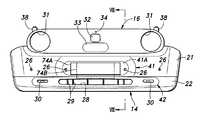
図2はフロントバンパーフェース14及びフロントパネル16の正面図である。図2に示されるように、フロントバンパーフェース14は、上側に配置された上フェース部材21と、下側に配置された下フェース部材22との2部材によって構成されている。上フェース部材21と下フェース部材22とは、概ね水平な分割面によって上下に分割されており、同程度の車幅方向寸法を有する一方、上フェース部材21の高さ寸法が下フェース部材22の高さ寸法よりも大きくなっている。 FIG. 2 is a front view of the
上フェース部材21の前面における車幅方向の中央には、ライセンスプレート74(図5参照)を取り付けるためのライセンスプレート取付部24が形成されている。ライセンスプレート取付部24は、ライセンスプレート74の上部を支持する。そのため、上フェース部材21の上側の(高い)位置に設けられている。上フェース部材21のライセンスプレート取付部24よりも若干低い位置には、複数のセンサ取付孔26が車幅方向に間隔を開けて設けられている。本実施形態では、ライセンスプレート取付部24の右側に2つ、左側に2つの合計4つのセンサ取付孔26が設けられている。各センサ取付孔26には上フェース部材21の裏側に取り付けられる障害物センサ76(図8参照)の検出部が配置される。 A license
下フェース部材22の車幅方向の中央には、車体4の前方の外気を前部空間3に取り入れるために前後に貫通する横長の外気導入開口28が形成されている。外気導入開口28には、上下方向に延在して上下の壁面を連結する複数のリブ29が設けられており、これにより外気導入開口28はグリル開口部を形成している。下フェース部材22の外気導入開口28の両側方には、フォグライトを取り付けるための1対のフォグライト取付孔30が前後に貫通する態様に形成されている。 At the center of the
フロントパネル16は横長の略長円形をなしており、左右の両端部にヘッドライト15が配置される円形のライト用開口31が形成されている。フロントパネル16の車幅方向の中央には、エンブレム32(標章)と電波を透過させる電波透過部材33とが上下に並んで設けられている。エンブレム32はフロントパネル16の上側領域に配置され、電波透過部材33はフロントパネル16の下側領域に配置されている。エンブレム32はフロントパネル16の前面に接着、嵌合などにより接合された略矩形の部材である。一方、電波透過部材33はフロントパネル16に形成された開口孔に嵌め込まれたフロントパネル16とは別の横長の長円形の部材である。 The
更に、フロントパネル16におけるエンブレム32の上方の上端近傍には、光を透過させる円形の光透過部材34が設けられている。光透過部材34は、フロントパネル16に形成された開口孔に嵌め込まれた透明又は半透明な板部材又はレンズであり、エンブレム32や電波透過部材33に比べて小さく形成されている。あるいは、フロントパネル16が透明又は半透明な樹脂成形品に塗装を施して形成されたものである場合には、光透過部材34は塗装を施されていないフロントパネル16の透明又は半透明な部分であってもよい。 Further, a circular
図3はフロントバンパーフェース14及びフロントパネル16の斜視図である。図3に示されるように、フロントバンパーフェース14及びフロントパネル16は、中央部が前方に突出する湾曲形状をなしており、それらの左右の側部は端部側ほど後方に位置するように傾斜している。 FIG. 3 is a perspective view of the
フロントパネル16は、上部にて概ね鉛直に延在する上部鉛直面36と、上部鉛直面36の下端に連続し、下部にて下方に向けて前方に傾斜する下部傾斜面37とを有している。電波透過部材33は下部傾斜面37に配置され、エンブレム32は上部鉛直面36に配置されている。電波透過部材33は、フロントパネル16に設けられるために目立ちやすいが、このようにフロントパネル16の上部鉛直面36と下部傾斜面37との一方に設けられることで目立ちにくくなっている。具体的には、車外の人の目に入る上部鉛直面36からの反射光と下部傾斜面37からの反射光とは見え方が異なることから、下部傾斜面37に設けられた電波透過部材33とフロントパネル16との境界が上部鉛直面36によって目立たなくなっている。 The
フロントパネル16の上部には、車体4の骨格部材に取り付けるための左右1対の外側取付片38及び左右1対の内側取付片39が設けられている。外側取付片38はフロントパネル16から後方且つ上方に延出するパネル取付片である。内側取付片39はフロントパネル16から後方且つ下方に延出するパネル取付片である。 A pair of left and right outer mounting
上フェース部材21の前面における車幅方向の中央には、横長の略長円形の凹部41が形成されている。ライセンスプレート取付部24は、凹部41の底面41Aにおける幅方向中央且つ上部に配置されている。言い換えれば、凹部41の底面41Aはライセンスプレート取付面をなしている。4つのセンサ取付孔26のうち、車幅方向の中央側の2つのセンサ取付孔26は、凹部41の底面41Aにおける左右の端部近傍に配置されている。 A horizontally long substantially
下フェース部材22の前面における車幅方向の中央には、外気導入開口28を取り囲んで底面42Aに外気導入開口28が位置するように湾曲形成された環状凹部42が設けられている。そのため、外気は環状凹部42によって外気導入開口28に集められ、外気導入開口28からの外気取り込み量が増大する。 At the center of the front surface of the
2つのフォグライト取付孔30は、環状凹部42の底面42Aにおける左右の側部に配置されている。このようにフォグライト取付孔30がフロントバンパーフェース14の凹んだ部分に設けられるため、フォグライトの照射範囲が縮小されることなくフォグライトの損傷が抑制される。 The two fog
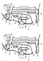
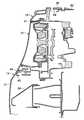
図4は図2中のIV−IV断面図である。図3及び図4に示されるように、電波透過部材33の上端は、フロントパネル16の下部傾斜面37と上部鉛直面36との境界、即ち上部鉛直面36の下端に位置している。上記のようにフロントパネル16に設けられために電波透過部材33は目立ちやすいが、このように電波透過部材33の上端が上部鉛直面36の下端に位置することにより、電波透過部材33がより目立たなくなっている。また、上部鉛直面36の光透過部材34と電波透過部材33との間の部分に比較的目立つエンブレム32が配置されていることにより、光透過部材34も目立たなくなっている。 FIG. 4 is a sectional view taken along line IV-IV in FIG. As shown in FIGS. 3 and 4, the upper end of the radio
フロントパネル16の下端には、前方に開放された有底の取付孔44(図4)が形成されている。上フェース部材21の上端には取付孔44に挿入されるべく後方に延出するバンパー取付片45(図4)が設けられている。フロントバンパーフェース14の上フェース部材21は、バンパー取付片45が取付孔44に挿入されることにより、フロントパネル16の前面と連続するように(面一になるように)前後方向の位置決めをされた状態でフロントパネル16に取り付けられる。 A bottomed mounting hole 44 (FIG. 4) opened forward is formed at the lower end of the
上フェース部材21の前面は、上部にてフロントパネル16の下端から下部傾斜面37を延長させるように下方に向けて前方に傾斜して延び、中間部から下部にかけて、下方に向けて後方に若干傾斜するように延びている。凹部41の底面41Aは概ね鉛直に延びている。したがって、凹部41の凹み量(周辺部に対する段差)は、上側で大きく、下側で小さくなるように変化している。即ち、凹部41の周辺部に対する段差が下部において上部よりも小さくなっている。 The front surface of the
上フェース部材21の後方には、車幅方向に延在するフロントバンパービーム50が配置されている。即ち、フロントバンパーフェース14はフロントバンパービーム50の前方に配置されている。フロントバンパービーム50の後方には、車体4の骨格部材であるフロントバルクヘッド52が車幅方向に延在するように配置されている。フロントバルクヘッド52は、アッパクロスメンバ53、ロアクロスメンバ54、及びアッパクロスメンバ53とロアクロスメンバ54とを連結する左右のサイドステイを備え、正面視で矩形の枠状をなしている。フロントバルクヘッド52は、左右の端部において左右のフロントサイドフレームに結合されている。フロントバンパービーム50は、左右のフロントサイドフレームの前端にエクステンション部材を介して取り付けられている。 A
フロントバンパービーム50は縦長の閉断面形状をなしている。フロントバンパービーム50の前面には、フロントバンパービーム50と協働して略三角形の閉断面を形成するように前方に突出するセーフティプレート58が取り付けられている。セーフティプレート58は、歩行者への衝突時に圧壊することで衝突エネルギーを吸収するエネルギー吸収部材(歩行者保護部材)である。セーフティプレート58は、フロントバンパーフェース14の後面に対して前端が隙間を空けるようにフロントバンパーフェース14の後方に配置されている。セーフティプレート58の前端は、上フェース部材21に形成された凹部41の上部に対応する高さに配置されている。 The
フロントバルクヘッド52の内側(アッパクロスメンバ53とロアクロスメンバ54との間)には、複数の熱交換器60が配置されている。これらの熱交換器60は、IPU(インテリジェントパワーユニット)冷却用やエアコンコンデンサなどである。これらの熱交換器60の後方にはシュラウド61に収容された冷却ファン62が設けられている。熱交換器60や冷却ファン62はフロントバルクヘッド52に支持される。熱交換器60の前方には、外気導入開口28から取り込んだ外気を熱交換器60へ導くエアガイド部材64が設けられている。 A plurality of
エアガイド部材64の下壁65は外気導入開口28の下縁の下方から概ね水平に後方へ延びている。エアガイド部材64の上壁66は外気導入開口28の上縁の上方から後方に向けて上方への傾斜角度を大きくするように上方に延びている。エアガイド部材64の前端はセーフティプレート58の前端よりも後方に位置している。このようなエアガイド部材64が設けられることにより、外気導入開口28が人の目に映りにくい車体下部に配置されていても、エアガイド部材64によって十分な量の外気を冷却機器に供給することができる。これにより、熱交換器60の冷却性能を失うことなく高いデザイン性の実現が可能になっている。 The
フロントバルクヘッド52のアッパクロスメンバ53には、熱交換器60の上方に配置され、複数の電気接続用コネクタを接続されるポート装置18の装置主部18Aが支持されている。また、アッパクロスメンバ53とフロントバンパービーム50との間には、支持部材68を介してアッパクロスメンバ53に支持されたレーダ装置70が設けられている。レーダ装置70は、電波透過部材33の後方の電波透過部材33から離間した位置に配置されており、ミリ波を前方に送信し、反射した電波を受信することで、前方の物体の有無及び物体までの距離を検出する。なお、電波透過部材33は下部傾斜面37にあるが、レーダ装置70は前方の車両を問題なく検知できる。一方、下部傾斜面37は上部鉛直面36に比べて雨や雪などが車両走行時に風圧で滑り落ちやすいため、電波透過部材33の後方に設けられたレーダ装置70の性能低下が抑制される。 The
フロントパネル16の上部には、マウント部71が一体に形成されており、このマウント部71には、マルチビューカメラとして車体前方及び車体下方(車体4近くの前方)を撮像する撮像装置72が取り付けられている。撮像装置72は、光透過部材34の後方に光透過部材34との間に若干の隙間を空けて配置されている。このように撮像装置72は、上部鉛直面36に設けられた光透過部材34の後方に設けられることにより、フロントバンパーフェース14下方の、車体4により近い領域を撮像することができる。 A
このように、下部傾斜面37に配置された電波透過部材33の後方にレーダ装置70が配置され、上部鉛直面36に配置された光透過部材34の後方に撮像装置72が配置されるため、軽衝突時にレーダ装置70や撮像装置72に影響が及びにくい。 In this way, the
フロントバンパーフェース14の大部分はセーフティプレート58の前端よりも前方に位置しており、ライセンスプレート取付面をなす凹部41の底面41Aもセーフティプレート58の前端よりも前方に位置している。一方、フロントバンパーフェース14の上端及びフロントパネル16の下端は、ライセンスプレート取付面をなす凹部41の底面41Aよりも後方且つセーフティプレート58の前端よりも後方に位置している。即ち、電波透過部材33を含むフロントパネル16の全体がライセンスプレート取付面をなす凹部41の底面41Aやセーフティプレート58の前端よりも後方に位置している。 Most of the
したがって、軽衝突時には衝撃が最初にナンバープレート取付面によって吸収され、次にセーフティプレート58によって吸収される。そのため、フロントパネル16の変形又は脱落が抑制される。また、電波透過部材33の変形又は脱落も抑制される。 Therefore, in the event of a light collision, the impact is first absorbed by the license plate mounting surface and then by the
上記のように、エアガイド部材64の前端もセーフティプレート58の前端よりも後方に位置している。そのため、軽衝突時におけるエアガイド部材64の変形も抑制され、エアガイド部材64に接続された部品の変形も併せて抑制される。 As described above, the front end of the
図5はライセンスプレート取付状態のフロントバンパーフェース14の正面図である。図5に示されるように、ライセンスプレート74(74A、74B)は、上端部をライセンスプレート取付部24(図2)に揃えて上フェース部材21に取り付けられる。ライセンスプレート74は国によって大きさや形状が様々であり、代表的なものとして、欧州で多く使用される横長な矩形状のもの(以下、横長のライセンスプレート74Aという。)と、日本で使用される比較的縦長(実際には横長)な矩形状のもの(以下、縦長のライセンスプレート74Bという。)とがある。図5には、前者を実線で示し、後者を想像線で示している。 FIG. 5 is a front view of the
図6はライセンスプレート取付状態の図2中のIV−IV断面に相当する図であり、(A)は横長のライセンスプレート74A取付状態を、(B)は縦長のライセンスプレート74B取付状態を示している。図5及び図6(A)に示されるように、上フェース部材21の底面41Aは、横長のライセンスプレート74Aの幅及び高さよりも大きな幅及び高さを有している。ライセンスプレート取付部24が凹部41の底面41Aの上部に設けられていることから、横長のライセンスプレート74Aの下端は凹部41の底面41Aの下端よりも上方に位置している。このようにライセンスプレート取付部24が凹部41に形成され、横長のライセンスプレート74Aを凹部41に収容するように上フェース部材21に取り付けることができるため、外観が損なわれない。 6A and 6B are views corresponding to the IV-IV cross section in FIG. 2 in the license plate mounted state, where FIG. 6A shows a horizontally
一方、縦長のライセンスプレート74Bの下端は、図5及び図6(B)に示されるように、凹部41の底面41Aの下端よりも下方に位置している。具体的には、縦長のライセンスプレート74Bの下端は、下フェース部材22に重なり且つ外気導入開口28の上場端よりも上方の位置に配置されている。上記のように凹部41の周辺部に対する段差は下部において上部よりも小さく、凹部41の下側部分は上側部分に比べて小さな段差を介して周辺部の上フェース部材21につながっているため、縦長のライセンスプレート74Bを凹部41から下方に延出するように取り付けることが可能になっている。 On the other hand, the lower end of the vertically
凹部41の底面41Aに設けられた2つのセンサ取付孔26は、これらのライセンスプレート74の両側方に、正面視でライセンスプレート74に重ならず且つライセンスプレート74に近接して配置されている。このようにセンサ取付孔26は凹部41に配置されることによって目立たなくなっている。 Two
図7はライセンスプレート取付状態のフロントバンパーフェース14の斜視図である。図7では、図5と同様に、横長のライセンスプレート74Aを実線で示し、縦長のライセンスプレート74Bを想像線で示している。上記のようにライセンスプレート74の下端が外気導入開口28の上端よりも上方に位置するため、ナンバープレートが外気導入開口28を閉鎖することはない。したがって、ナンバープレートが外気導入開口28の走行風取り込み性能を阻害することはない。 FIG. 7 is a perspective view of the
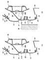
図8は図5中のVIII−VIII断面図であって、(A)通常時、(B)前突時を示している。図8(A)に示されるように、センサ取付孔26には障害物センサ76が取り付けられている。障害物センサ76はセーフティプレート58よりも低い位置に配置されている。セーフティプレート58の下面には、障害物センサ76よりも大きな開口58Aが形成されている。また、障害物センサ76は、ライセンスプレート74(図7)に近接して配置されることにより、機能を損なうことなく且つ検出部が目立つことなく配置されている。 FIG. 8 is a cross-sectional view taken along the line VIII-VIII in FIG. 5, showing (A) normal time and (B) front collision. As shown in FIG. 8A, an
図8(B)に示されるように、電気自動車1がセーフティプレート58の前端の高さよりも低い障害物78に衝突すると、フロントバンパーフェース14の下部は、セーフティプレート58の前端を支点にして後方に回動する。この際にフロントバンパーフェース14と共に後方に回動する障害物センサ76に対応するセーフティプレート58の位置に開口58Aが設けられている。言い換えれば、セーフティプレート58の下面の、前突時にセーフティプレート58の前端を支点にして後方に回動する障害物センサ76に対応する位置に、障害物センサ76を収容可能な大きさの開口58Aが形成されている。 As shown in FIG. 8B, when the electric vehicle 1 collides with an
したがって、電気自動車1の軽衝突によって障害物センサ76がセーフティプレート58の前端を支点にして上フェース部材21と共に後方に回動しても、障害物センサ76はセーフティプレート58に衝突せずに開口58Aに収容される。そのため、セーフティプレート58とフロントバンパーフェース14との間に挟まれることがない。これにより軽衝突によって障害物センサ76が壊れることが抑制される。 Therefore, even if the
図9はフロントバンパービーム50と障害物センサ76との位置関係を示す正面図である。図9に示されるように、フロントバンパービーム50の上縁は車幅方向の全長にわたって略一体の高さに位置している。一方、フロントバンパービーム50の下縁は車幅方向の中央部において両側方部よりも下方に位置している。即ち、フロントバンパービーム50は車幅方向の中央部において両側方部よりも高さが大きく、その分だけ下方に突出した下向突出部50Aを車幅方向の中央に備えている。言い換えれば、フロントバンパービーム50の下縁は両側方部にて上方に凹陥している。 FIG. 9 is a front view showing the positional relationship between the
4つの障害物センサ76は、車幅方向においてフロントバンパービーム50の両側方部に対応する位置に配置されている。また、4つの障害物センサ76は、上下方向においてフロントバンパービーム50の下向突出部50Aに対応する位置、即ち下向突出部50Aの両側方の、正面視においてフロントバンパービーム50に重ならない位置に配置されている。 The four
電気自動車1がセーフティプレート58の前端の高さよりも高い障害物78に衝突すると、フロントバンパーフェース14がセーフティプレート58を圧壊させながら全体的に後方に移動する。即ち、障害物センサ76がフロントバンパーフェース14と共に後退する。この際、上記配置により、障害物センサ76がフロントバンパービーム50に衝突することや、障害物センサ76がフロントバンパーフェース14とフロントバンパービーム50との間に挟まれることが抑制される。 When the electric vehicle 1 collides with an
図10はフロントバンパーフェース14の上部の取付構造の斜視図である。図10に示されるように、フロントバルクヘッド52のアッパクロスメンバ53の左右の端部は、左右のアッパメンバ80の対応する側の前端に対し、連結部材82を介して連結されている。言い換えれば、左右のアッパメンバ80の前端とフロントバルクヘッド52の上部との間に左右の連結部材82が架設されている。内側取付片39は、対応する側の連結部材82の内端部分に固定される。外側取付片38は、対応する側の連結部材82の外端部分に固定される。 FIG. 10 is a perspective view of the mounting structure of the upper part of the
図11は図10中のXI−XI断面図であり、外側取付片38の断面を示している。図11に併せて示されるように、フロントパネル16のライト用開口31に配置されたヘッドライト15の上面には、上方且つ後方に延出する支持片84が一体に形成されている。外側取付片38は、連結部材82との間にこの支持片84を挟んで連結部材82に固定されている。言い換えれば、外側取付片38は、対応する側のヘッドライト15を支持して対応する側の連結部材82に固定されている。そのため、車体4の骨格部材をなす連結部材82にヘッドライト15を介してフロントパネル16が固定され、フロントパネル16を介して上フェース部材21が安定して支持される。 FIG. 11 is a cross-sectional view taken along the line XI-XI in FIG. 10, showing a cross section of the outer mounting
電気自動車1の車体4の前部は以上のように構成されている。このように、図2〜図4などに示されるフロントバンパーフェース14は、ライセンスプレート取付部24が形成された上フェース部材21と、外気導入開口28が形成された下フェース部材22とからなるため、両フェース部材の形状及びその金型の形状が簡素化され、設計自由度が高くなる。また、フロントバンパーフェース14が上フェース部材21と下フェース部材22との分割体によって構成されるため、ライセンスプレート取付部24や外気導入開口28の形状変更を容易に行うことができる。 The front portion of the vehicle body 4 of the electric vehicle 1 is configured as described above. As described above, the
また、本実施形態では、フロントパネル16の下部傾斜面37及びフロントバンパーフェース14の上フェース部材21がフロントパネル16の上部鉛直面36よりも前方に突出している。そして図4に示されるように、フロントバンパービーム50の前面に、歩行者への衝突時に圧壊可能な歩行者保護部材としてのセーフティプレート58が設けられている。これにより、車体4の前部空間3を小さくすることなく、車体前部の前後方向長さを短くしつつ、十分なサイズの歩行者保護部 材の配置によって安全性能の確保が可能になっている。したがって、車体4の前部空間3を小さくしやすいという電気自動車1のメリットが更に拡張される。 Further, in the present embodiment, the lower
以上で具体的実施形態の説明を終えるが、本発明は上記実施形態に限定されることなく幅広く変形実施することができる。例えば、上記実施形態では、本発明が一例として電気自動車1に適用されているが、ハイブリッド車やエンジン駆動の自動車に適用されてもよい。また、各部材や部位の具体的構成や配置、数量、素材など、本発明の趣旨を逸脱しない範囲であれば適宜変更可能である。一方、上記実施形態に示した各構成要素は必ずしも全てが必須ではなく、適宜選択することができる。 Although the description of the specific embodiment is completed above, the present invention can be widely modified without being limited to the above embodiment. For example, in the above embodiment, the present invention is applied to the electric vehicle 1 as an example, but it may be applied to a hybrid vehicle or an engine-driven vehicle. Further, the specific configuration, arrangement, quantity, material, etc. of each member or portion can be appropriately changed as long as it does not deviate from the gist of the present invention. On the other hand, not all of the components shown in the above embodiments are essential, and they can be appropriately selected.
1 電気自動車
4 車体
14 フロントバンパーフェース
15 ヘッドライト
16 フロントパネル
21 上フェース部材
22 下フェース部材
24 ライセンスプレート取付部
28 外気導入開口
30 フォグライト取付孔
31 ライト用開口
36 上部鉛直面
37 下部傾斜面
38 外側取付片(パネル取付片)
41 凹部
42 環状凹部
42A 底面
44 取付孔
45 バンパー取付片
50 フロントバンパービーム
52 フロントバルクヘッド
58 セーフティプレート(歩行者保護部材)
58A 開口
60 熱交換器
64 エアガイド部材
74 ライセンスプレート
74A 横長のライセンスプレート
74B 縦長のライセンスプレート
76 障害物センサ
80 アッパメンバ
82 連結部材1 Electric vehicle 4
41
Claims (10)
Translated fromJapanese前記フロントバンパーフェースが上フェース部材と下フェース部材とを有し、前記上フェース部材にライセンスプレート取付部が形成され、前記下フェース部材に外気導入開口が形成され、
前記フロントバンパービームの前面に、前記上フェース部材との間に配置されて歩行者への衝突時に圧壊可能な歩行者保護部材が設けられ、
前記上フェース部材の前記歩行者保護部材よりも下方の位置に障害物センサが設けられ、
前記歩行者保護部材の下面には、前突時に前記歩行者保護部材の前端を支点にして後方に回動する前記障害物センサに対応する位置に、前記障害物センサを収容可能な大きさの開口が形成されていることを特徴とする車体前部構造。With a front bumper face located in front of the front bumper beam
The front bumper face has an upper face member and a lower face member, a license plate mounting portion is formed on the upper face member, and an outside air introduction opening is formed on the lower face member.
A pedestrian protection member is provided on the front surface of the front bumper beam, which is arranged between the front bumper beam and can be crushed when colliding with a pedestrian.
An obstacle sensor is provided at a position below the pedestrian protection member of the upper face member.
The lower surface of the pedestrian protection member has a size capable of accommodating the obstacle sensor at a position corresponding to the obstacle sensor that rotates backward with the front end of the pedestrian protection member as a fulcrum at the time of a front collision. The front structure of the vehicle body is characterizedby having an opening .
前記フロントパネルが、上部にて概ね鉛直に延在する上部鉛直面と、前記上部鉛直面の下端に連続し、下方に向けて前方へ傾斜した下部傾斜面とを有し、
前記下部傾斜面及び前記上フェース部材が前記上部鉛直面よりも前方に突出していることを特徴とする請求項1に記載の車体前部構造。Further provided with a front panel arranged above the upper face member and formed with a light opening into which the headlights are arranged.
The front panel has an upper vertical surface that extends substantially vertically at the upper part and a lower inclined surface that is continuous with the lower end of the upper vertical surface and is inclined forward downward.
Vehicle body front structure according to claim 1 wherein the lower inclined surface and the upper face member, characterized inthat protrudes forward from the upper vertical surface.
前記外気導入開口から取り込んだ外気を前記熱交換器へ導くエアガイド部材とを更に備えることを特徴とする請求項1に記載の車体前部構造。A heat exchanger located behind the front bumper beam,
The vehicle body front structure according to claim 1, further comprising an air guide member that guides the outside air taken in from the outside air introduction opening to the heat exchanger.
前記凹部の周辺部に対する段差が下部において上部よりも小さいことを特徴とする請求項1に記載の車体前部構造。The license plate mounting portion is formed in a recess formed on the front surface of the upper face member.
The vehicle body front structure according to claim 1, wherein the step with respect to the peripheral portion of the recess is smaller at the lower portion than at the upper portion.
前記障害物センサが、前記上フェース部材の前記凹部にてライセンスプレートに近接して配置されていることを特徴とする請求項1に記載の車体前部構造。The license plate mounting portion is formed in a recess formed on the front surface of the upper face member.
The vehicle body front structure according to claim1 , wherein the obstacle sensor is arranged in the recessed portion of the upper face member in the vicinity of the license plate.
前記フロントバンパーフェースが上フェース部材と下フェース部材とを有し、前記上フェース部材にライセンスプレート取付部が形成され、前記下フェース部材に外気導入開口が形成され、
前記上フェース部材の上方に配置され、ヘッドライトが配置されるライト用開口が形成されたフロントパネルと、
前記フロントバンパービームの後方に配置されたフロントバルクヘッドと、
左右のアッパメンバの前端と前記フロントバルクヘッドの上部との間に架設された左右の連結部材とを更に備え、
前記フロントパネルの上部には、前記ヘッドライトを支持して左右の前記連結部材に固定されるパネル取付片が設けられ、
前記フロントパネルの下部には前方に開放された取付孔が形成され、
前記上フェース部材の上部には前記取付孔に挿入されるバンパー取付片が設けられていることを特徴とする車体前部構造。With a front bumper face located in front of the front bumper beam
The front bumper face has an upper face member and a lower face member, a license plate mounting portion is formed on the upper face member, and an outside air introduction opening is formed on the lower face member.
A front panel arranged above the upper face member and having a light opening for arranging headlights, and a front panel.
With the front bulkhead located behind the front bumper beam,
Further provided with left and right connecting members erected between the front ends of the left and right upper members and the upper portion of the front bulkhead.
A panel mounting piece that supports the headlight and is fixed to the left and right connecting members is provided on the upper portion of the front panel.
A mounting hole opened forward is formed in the lower part of the front panel.
A vehicle body front structure characterizedin that a bumper mounting piece inserted into the mounting hole is provided on the upper portion of the upper face member .
前記下部傾斜面及び前記上フェース部材が前記上部鉛直面よりも前方に突出しており、
前記フロントバンパービームの前面に、前記上フェース部材との間に配置されて歩行者への衝突時に圧壊可能な歩行者保護部材が設けられていることを特徴とする請求項9に記載の車体前部構造。Before SL front panel includes an upper vertical plane generally vertically extending at the top, and continuous to the lower end of the upper vertical surface and a lower inclined surface inclined forwardly downward,
The lower inclined surface and the upper face member project forward from the upper vertical surface.
The front portion of the vehicle body according to claim9 , wherein a pedestrian protection member arranged between the front bumper beam and the front bumper beam and capable of being crushed in the event of a collision with a pedestrian is provided. Construction.
Priority Applications (3)
| Application Number | Priority Date | Filing Date | Title |
|---|---|---|---|
| JP2018179734AJP6786561B2 (en) | 2018-09-26 | 2018-09-26 | Body front structure |
| US16/564,897US10967821B2 (en) | 2018-09-26 | 2019-09-09 | Vehicle body front structure |
| CN201910910506.9ACN110949299B (en) | 2018-09-26 | 2019-09-25 | Vehicle body front structure |
Applications Claiming Priority (1)
| Application Number | Priority Date | Filing Date | Title |
|---|---|---|---|
| JP2018179734AJP6786561B2 (en) | 2018-09-26 | 2018-09-26 | Body front structure |
Publications (2)
| Publication Number | Publication Date |
|---|---|
| JP2020050059A JP2020050059A (en) | 2020-04-02 |
| JP6786561B2true JP6786561B2 (en) | 2020-11-18 |
Family
ID=69884126
Family Applications (1)
| Application Number | Title | Priority Date | Filing Date |
|---|---|---|---|
| JP2018179734AExpired - Fee RelatedJP6786561B2 (en) | 2018-09-26 | 2018-09-26 | Body front structure |
Country Status (3)
| Country | Link |
|---|---|
| US (1) | US10967821B2 (en) |
| JP (1) | JP6786561B2 (en) |
| CN (1) | CN110949299B (en) |
Families Citing this family (23)
| Publication number | Priority date | Publication date | Assignee | Title |
|---|---|---|---|---|
| DE102017009057B4 (en)* | 2017-09-27 | 2019-07-11 | Audi Ag | Arrangement of a sensor-active surface having sensor on an external attachment of a vehicle |
| JP6786561B2 (en)* | 2018-09-26 | 2020-11-18 | 本田技研工業株式会社 | Body front structure |
| JP6778287B2 (en)* | 2019-02-15 | 2020-10-28 | 本田技研工業株式会社 | Energy absorption structure |
| JP2021019413A (en)* | 2019-07-19 | 2021-02-15 | トヨタ自動車株式会社 | Exterior structure for vehicle |
| US11214313B2 (en)* | 2019-12-09 | 2022-01-04 | Ford Global Technologies, Llc | Vehicle assemblies with loose layered build components |
| CN113147641B (en)* | 2021-03-03 | 2022-07-22 | 一汽奔腾轿车有限公司 | Bumper mounting structure beneficial to pedestrian protection |
| GB2612573B (en)* | 2021-10-20 | 2024-01-10 | Jaguar Land Rover Ltd | Vehicle front end alignment improvements |
| CN114103852A (en)* | 2021-11-14 | 2022-03-01 | 襄阳光瑞汽车零部件有限公司 | Lightweight truck front bumper and manufacturing method thereof |
| JP1750717S (en)* | 2022-03-14 | 2023-08-14 | automotive hood | |
| FR3139070A1 (en)* | 2022-08-31 | 2024-03-01 | Psa Automobiles Sa | Motor vehicle one-piece bumper skin element |
| ZAA202300507S (en)* | 2022-10-25 | 2024-08-28 | Bayerische Motoren Werke Ag | Motor vehicles |
| FR3143483A1 (en)* | 2022-12-19 | 2024-06-21 | Compagnie Plastic Omnium Se | Front panel for motor vehicle |
| FR3143482A1 (en)* | 2022-12-19 | 2024-06-21 | Compagnie Plastic Omnium Se | Front panel for motor vehicle |
| JP7452738B1 (en) | 2023-04-25 | 2024-03-19 | いすゞ自動車株式会社 | Front panel structure and front panel fixing method |
| DE102023111178B3 (en) | 2023-05-02 | 2024-07-25 | Dr. Ing. H.C. F. Porsche Aktiengesellschaft | Vehicle body front structure and motor vehicle |
| FR3149586A1 (en)* | 2023-06-12 | 2024-12-13 | Psa Automobiles Sa | Fixing device and locking interface for a bumper sensor. |
| CN116811564A (en)* | 2023-07-05 | 2023-09-29 | 浙江吉利控股集团有限公司 | Automobile air inlet structure, automobile body assembly and automobile |
| FR3151286B1 (en)* | 2023-07-19 | 2025-07-25 | Renault Sas | Method of assembling electric motor vehicles and installation for implementation |
| US12435660B2 (en)* | 2023-08-04 | 2025-10-07 | Kawasaki Motors, Ltd. | Off-road vehicle |
| JP2025112868A (en)* | 2024-01-22 | 2025-08-01 | トヨタ自動車株式会社 | vehicle |
| EP4624272A1 (en)* | 2024-03-29 | 2025-10-01 | Suzuki Motor Corporation | Vehicle structure |
| USD1046724S1 (en)* | 2024-06-06 | 2024-10-15 | Pu Zhu | Hood for a vehicle |
| USD1046725S1 (en)* | 2024-06-06 | 2024-10-15 | Pu Zhu | Hood for a vehicle |
Family Cites Families (38)
| Publication number | Priority date | Publication date | Assignee | Title |
|---|---|---|---|---|
| JPS6324056U (en)* | 1986-08-01 | 1988-02-17 | ||
| JPH1053080A (en) | 1996-08-09 | 1998-02-24 | Suzuki Motor Corp | Automotive bumper |
| JP3912479B2 (en) | 2001-01-22 | 2007-05-09 | スズキ株式会社 | Front grille structure |
| CN1289338C (en)* | 2001-09-14 | 2006-12-13 | 本田技研工业株式会社 | Front grill impact-absorbing structure for a vehicle |
| FR2832687B1 (en)* | 2001-11-29 | 2004-03-05 | Plastic Omnium Cie | MOTOR VEHICLE BODY PIECE HAVING A DEPTH APPEARANCE MARKED |
| DE502004008774D1 (en) | 2003-02-19 | 2009-02-12 | Fraport Ag Frankfurt Airport S | GUIDANCE SYSTEM AND METHOD FOR MOVING THE PATH |
| JP4552182B2 (en)* | 2004-08-10 | 2010-09-29 | スズキ株式会社 | Front bumper structure |
| JP2007055311A (en)* | 2005-08-22 | 2007-03-08 | Mazda Motor Corp | Front part structure of vehicle |
| US7347489B2 (en)* | 2005-09-13 | 2008-03-25 | Chrysler Llc | Front end for a vehicle and method for making same |
| JP2009120153A (en)* | 2007-11-19 | 2009-06-04 | Mazda Motor Corp | Front structure of automobile |
| JP4836977B2 (en)* | 2008-02-29 | 2011-12-14 | 本田技研工業株式会社 | Sensor layout |
| US7644966B2 (en)* | 2008-02-29 | 2010-01-12 | Nissan Technical Center North America, Inc. | Vehicle bumper fascia retainer |
| JP2009220676A (en)* | 2008-03-14 | 2009-10-01 | Honda Motor Co Ltd | Front structure for vehicle |
| CN201291825Y (en)* | 2008-09-09 | 2009-08-19 | 上海通用汽车有限公司 | Novel protection device for leg of walker |
| WO2011151917A1 (en)* | 2010-06-03 | 2011-12-08 | トヨタ自動車株式会社 | Cooling-wind introduction structure |
| JP5510389B2 (en)* | 2010-09-01 | 2014-06-04 | マツダ株式会社 | Vehicle front structure |
| BR112013012119A2 (en)* | 2010-11-19 | 2016-09-27 | Honda Motor Co Ltd | vehicle body structure and vehicle body structure |
| JP5373004B2 (en)* | 2011-07-20 | 2013-12-18 | 本田技研工業株式会社 | Auto body front structure |
| US8517461B2 (en)* | 2011-07-29 | 2013-08-27 | Nissan North America, Inc. | Vehicle body structure |
| JP5772538B2 (en)* | 2011-11-18 | 2015-09-02 | トヨタ自動車株式会社 | Cooling air introduction structure |
| WO2013161010A1 (en)* | 2012-04-24 | 2013-10-31 | トヨタ自動車株式会社 | Cooling device for vehicle |
| US9222288B2 (en)* | 2012-09-01 | 2015-12-29 | GM Global Technology Operations LLC | Integrated hood latch keeper for a grill opening reinforcement structure |
| US20150183384A1 (en)* | 2013-06-20 | 2015-07-02 | Jun Mendoza | Vehicle registration mounting assembly and method |
| CN105460080B (en)* | 2014-09-25 | 2017-11-28 | 翰昂系统株式会社 | Vehicle carrier rack |
| JP6555476B2 (en)* | 2015-10-16 | 2019-08-07 | スズキ株式会社 | Vehicle front structure |
| JP6285977B2 (en)* | 2016-03-28 | 2018-02-28 | 本田技研工業株式会社 | Bumper for vehicle |
| JP6319365B2 (en)* | 2016-06-07 | 2018-05-09 | マツダ株式会社 | Front body structure |
| DE102016122288A1 (en)* | 2016-11-21 | 2018-05-24 | Dr. Ing. H.C. F. Porsche Aktiengesellschaft | Vehicle front structure |
| US10704756B2 (en)* | 2017-01-04 | 2020-07-07 | Ford Global Technologies, Llc | Loose layered build components and vehicle front end assembly strategy |
| JP2018111367A (en)* | 2017-01-10 | 2018-07-19 | トヨタ自動車株式会社 | Vehicular periphery detection sensor mounting mechanism |
| WO2018169552A1 (en)* | 2017-03-17 | 2018-09-20 | Nissan North America, Inc. | Vehicle bumper assembly |
| JP6805942B2 (en)* | 2017-04-06 | 2020-12-23 | トヨタ自動車株式会社 | Vehicle front structure |
| JP6872517B2 (en)* | 2018-09-26 | 2021-05-19 | 本田技研工業株式会社 | Body front structure |
| JP6786561B2 (en)* | 2018-09-26 | 2020-11-18 | 本田技研工業株式会社 | Body front structure |
| JP6786560B2 (en)* | 2018-09-26 | 2020-11-18 | 本田技研工業株式会社 | Body front structure |
| US10850697B2 (en)* | 2018-11-30 | 2020-12-01 | Nissan North America, Inc. | Energy absorber for sensor protection |
| JP6960389B2 (en)* | 2018-12-04 | 2021-11-05 | 本田技研工業株式会社 | Detector and vehicle |
| JP6994479B2 (en)* | 2019-05-13 | 2022-02-04 | 本田技研工業株式会社 | External sensor mounting part structure |
- 2018
- 2018-09-26JPJP2018179734Apatent/JP6786561B2/ennot_activeExpired - Fee Related
- 2019
- 2019-09-09USUS16/564,897patent/US10967821B2/ennot_activeExpired - Fee Related
- 2019-09-25CNCN201910910506.9Apatent/CN110949299B/enactiveActive
Also Published As
| Publication number | Publication date |
|---|---|
| US20200094759A1 (en) | 2020-03-26 |
| US10967821B2 (en) | 2021-04-06 |
| JP2020050059A (en) | 2020-04-02 |
| CN110949299B (en) | 2023-04-11 |
| CN110949299A (en) | 2020-04-03 |
Similar Documents
| Publication | Publication Date | Title |
|---|---|---|
| JP6786561B2 (en) | Body front structure | |
| JP6786560B2 (en) | Body front structure | |
| CN100398381C (en) | Vehicle front body structure | |
| US8267446B2 (en) | Motor vehicle front-end panel assembly comprising a shield | |
| US6945593B2 (en) | End part for a vehicle engine hood | |
| JP6840114B2 (en) | Body front structure | |
| US11237461B2 (en) | Transport equipment and sensor bracket | |
| JP6764453B2 (en) | Body front structure | |
| JP2009234376A (en) | Vehicle front body structure | |
| US11479194B2 (en) | Vehicle front structure | |
| CN116890778A (en) | Front structure of vehicle body | |
| RU2504489C2 (en) | Vehicle front fender attachment assy | |
| US11465688B2 (en) | Vehicle front structure | |
| CN208813315U (en) | Fan heater pressure chamber plate assembly and vehicle | |
| EP3808606B1 (en) | Vehicle front structure, and vehicle | |
| CN214165136U (en) | Wind window crossbeam structure and car | |
| JP5880414B2 (en) | Automobile leg mounting structure | |
| JP7264927B2 (en) | Body front member and body front structure | |
| JP6725618B2 (en) | Body front structure | |
| JP6224398B2 (en) | Vehicle front hood | |
| JP6561807B2 (en) | Hood structure with pedestrian protection airbag | |
| JP2024065286A (en) | Vehicle front structure | |
| CN116890777A (en) | Body front structure | |
| KR20100050112A (en) | Radiator grill cover comprising upper stiffener | |
| JP2001138839A (en) | Disposition structure of bumper |
Legal Events
| Date | Code | Title | Description |
|---|---|---|---|
| A621 | Written request for application examination | Free format text:JAPANESE INTERMEDIATE CODE: A621 Effective date:20190531 | |
| A131 | Notification of reasons for refusal | Free format text:JAPANESE INTERMEDIATE CODE: A131 Effective date:20200818 | |
| A521 | Request for written amendment filed | Free format text:JAPANESE INTERMEDIATE CODE: A523 Effective date:20201012 | |
| TRDD | Decision of grant or rejection written | ||
| A01 | Written decision to grant a patent or to grant a registration (utility model) | Free format text:JAPANESE INTERMEDIATE CODE: A01 Effective date:20201020 | |
| A61 | First payment of annual fees (during grant procedure) | Free format text:JAPANESE INTERMEDIATE CODE: A61 Effective date:20201028 | |
| R150 | Certificate of patent or registration of utility model | Ref document number:6786561 Country of ref document:JP Free format text:JAPANESE INTERMEDIATE CODE: R150 | |
| LAPS | Cancellation because of no payment of annual fees |