JP6784271B2 - Change detection device, maintenance management system, change detection method, program and recording medium - Google Patents
Change detection device, maintenance management system, change detection method, program and recording mediumDownload PDFInfo
- Publication number
- JP6784271B2 JP6784271B2JP2018051695AJP2018051695AJP6784271B2JP 6784271 B2JP6784271 B2JP 6784271B2JP 2018051695 AJP2018051695 AJP 2018051695AJP 2018051695 AJP2018051695 AJP 2018051695AJP 6784271 B2JP6784271 B2JP 6784271B2
- Authority
- JP
- Japan
- Prior art keywords
- change
- detection
- value
- setting parameter
- parameter
- Prior art date
- Legal status (The legal status is an assumption and is not a legal conclusion. Google has not performed a legal analysis and makes no representation as to the accuracy of the status listed.)
- Active
Links
Images


Classifications
- G—PHYSICS
- G06—COMPUTING OR CALCULATING; COUNTING
- G06F—ELECTRIC DIGITAL DATA PROCESSING
- G06F16/00—Information retrieval; Database structures therefor; File system structures therefor
- G06F16/20—Information retrieval; Database structures therefor; File system structures therefor of structured data, e.g. relational data
- G06F16/23—Updating
- G06F16/2358—Change logging, detection, and notification
- G—PHYSICS
- G05—CONTROLLING; REGULATING
- G05B—CONTROL OR REGULATING SYSTEMS IN GENERAL; FUNCTIONAL ELEMENTS OF SUCH SYSTEMS; MONITORING OR TESTING ARRANGEMENTS FOR SUCH SYSTEMS OR ELEMENTS
- G05B19/00—Programme-control systems
- G05B19/02—Programme-control systems electric
- G05B19/04—Programme control other than numerical control, i.e. in sequence controllers or logic controllers
- G05B19/042—Programme control other than numerical control, i.e. in sequence controllers or logic controllers using digital processors
- G—PHYSICS
- G06—COMPUTING OR CALCULATING; COUNTING
- G06F—ELECTRIC DIGITAL DATA PROCESSING
- G06F16/00—Information retrieval; Database structures therefor; File system structures therefor
- G06F16/20—Information retrieval; Database structures therefor; File system structures therefor of structured data, e.g. relational data
- G06F16/22—Indexing; Data structures therefor; Storage structures
- G—PHYSICS
- G06—COMPUTING OR CALCULATING; COUNTING
- G06F—ELECTRIC DIGITAL DATA PROCESSING
- G06F16/00—Information retrieval; Database structures therefor; File system structures therefor
- G06F16/90—Details of database functions independent of the retrieved data types
- G06F16/93—Document management systems
- G—PHYSICS
- G05—CONTROLLING; REGULATING
- G05B—CONTROL OR REGULATING SYSTEMS IN GENERAL; FUNCTIONAL ELEMENTS OF SUCH SYSTEMS; MONITORING OR TESTING ARRANGEMENTS FOR SUCH SYSTEMS OR ELEMENTS
- G05B2219/00—Program-control systems
- G05B2219/20—Pc systems
- G05B2219/23—Pc programming
- G05B2219/23335—History, log of program modifications
- G—PHYSICS
- G05—CONTROLLING; REGULATING
- G05B—CONTROL OR REGULATING SYSTEMS IN GENERAL; FUNCTIONAL ELEMENTS OF SUCH SYSTEMS; MONITORING OR TESTING ARRANGEMENTS FOR SUCH SYSTEMS OR ELEMENTS
- G05B2219/00—Program-control systems
- G05B2219/20—Pc systems
- G05B2219/25—Pc structure of the system
- G05B2219/25101—Detect connected module, load corresponding parameters, variables into module
- G—PHYSICS
- G05—CONTROLLING; REGULATING
- G05B—CONTROL OR REGULATING SYSTEMS IN GENERAL; FUNCTIONAL ELEMENTS OF SUCH SYSTEMS; MONITORING OR TESTING ARRANGEMENTS FOR SUCH SYSTEMS OR ELEMENTS
- G05B2219/00—Program-control systems
- G05B2219/30—Nc systems
- G05B2219/32—Operator till task planning
- G05B2219/32235—Sharing of data between process control and maintenance management computers
Landscapes
- Engineering & Computer Science (AREA)
- Theoretical Computer Science (AREA)
- General Physics & Mathematics (AREA)
- Physics & Mathematics (AREA)
- Databases & Information Systems (AREA)
- General Engineering & Computer Science (AREA)
- Data Mining & Analysis (AREA)
- Automation & Control Theory (AREA)
- Software Systems (AREA)
- Business, Economics & Management (AREA)
- General Business, Economics & Management (AREA)
- Testing And Monitoring For Control Systems (AREA)
- Programmable Controllers (AREA)
Description
Translated fromJapanese本発明は、変更検出装置、保全管理システム、変更検出方法、プログラムおよび記録媒体に関する。 The present invention relates to a change detection device, a maintenance management system, a change detection method, a program and a recording medium.
従来、プラントなどの設備においてはフィールド機器が設置される現場と管理室・計器室等とが離れているため(例えば、特許文献1参照)、現場作業者がフィールド機器の設定パラメータの値を変更した場合に、変更の有無および内容について管理者と正しく情報共有されないことがあり得る。
特許文献1 特開2006−157865号公報Conventionally, in equipment such as a plant, the site where the field equipment is installed is separated from the control room / instrument room (see, for example, Patent Document 1), so that the field worker changes the value of the setting parameter of the field equipment. In that case, information may not be shared correctly with the administrator regarding the presence or absence of changes and the contents.
近年、設定パラメータの値の変更の有無および内容について正確に情報共有したいとの要望がある。 In recent years, there has been a demand for accurate information sharing regarding the presence or absence of changes in setting parameter values and their contents.
上記課題を解決するために、本発明の第1の態様においては、変更検出装置が提供される。変更検出装置は、フィールド機器が有する少なくとも1つの設定パラメータの値を予め定められた時間間隔で取得するパラメータ取得部を備えてよい。変更検出装置は、設定パラメータの値が変更されたか否かを検出する変更検出部を備えてよい。変更検出装置は、設定パラメータの値の変更が検出されたことに応じて、変更情報を出力する変更情報出力部を備えてよい。 In order to solve the above problems, a change detection device is provided in the first aspect of the present invention. The change detection device may include a parameter acquisition unit that acquires the value of at least one setting parameter of the field device at predetermined time intervals. The change detection device may include a change detection unit that detects whether or not the value of the setting parameter has been changed. The change detection device may include a change information output unit that outputs change information in response to the detection of a change in the value of the setting parameter.
変更情報出力部は、複数のフィールド機器のそれぞれについて機器固有情報および設定パラメータの値を記憶する機器台帳を備える保全管理装置へと変更情報を送信してよい。 The change information output unit may transmit change information to a maintenance management device having a device ledger that stores device-specific information and setting parameter values for each of the plurality of field devices.
変更検出装置は、フィールド機器が有する複数の設定パラメータのうち、変更の検出対象とする設定パラメータを指定する検出対象リストを取得する検出対象リスト取得部を更に備えてよい。パラメータ取得部は、検出対象リストに含まれるそれぞれの設定パラメータの値を取得してよい。 The change detection device may further include a detection target list acquisition unit that acquires a detection target list that specifies a setting parameter to be detected for change among a plurality of setting parameters of the field device. The parameter acquisition unit may acquire the value of each setting parameter included in the detection target list.
変更検出装置は、複数の設定パラメータのそれぞれが変更される頻度に基づいて、変更の検出対象とする設定パラメータを選択する設定パラメータ選択部を更に備えてよい。 The change detection device may further include a setting parameter selection unit that selects a setting parameter for which a change is detected based on the frequency with which each of the plurality of setting parameters is changed.
変更検出部は、新たに取得された設定パラメータの値が、以前に取得された設定パラメータの値と同一でないことに応じて、設定パラメータの値が変更されたことを検出してよい。 The change detection unit may detect that the value of the setting parameter has been changed depending on that the value of the newly acquired setting parameter is not the same as the value of the previously acquired setting parameter.
パラメータ取得部は、設定パラメータの値の変更が検出されたことに応じて、変更が検出された設定パラメータに関連づけられた関連設定パラメータの値を更に取得してよい。変更情報出力部は、取得された関連設定パラメータの値を含む変更情報を出力してよい。 The parameter acquisition unit may further acquire the value of the related setting parameter associated with the setting parameter in which the change is detected, in response to the detection of the change in the value of the setting parameter. The change information output unit may output change information including the acquired values of the related setting parameters.
パラメータ取得部は、変更の検出対象とするいずれかの設定パラメータの値の変更が検出されたことに応じて、変更の検出対象としない複数の対象外設定パラメータの値を更に取得してよい。変更情報出力部は、取得された複数の対象外設定パラメータの値を含む変更情報を出力してよい。 The parameter acquisition unit may further acquire the values of a plurality of non-target setting parameters that are not the target of detection of the change, depending on the detection of the change of the value of any of the setting parameters whose change is to be detected. The change information output unit may output change information including the values of a plurality of acquired non-target setting parameters.
変更検出装置は、フィールド機器が検知できずパラメータ取得部がフィールド機器から設定パラメータの値を取得できないことに応じて、フィールド機器が非検知であることを示す非検知情報を出力する非検知情報出力部を更に備えてよい。 The change detection device outputs non-detection information indicating that the field device is non-detected in response to the fact that the field device cannot detect and the parameter acquisition unit cannot acquire the value of the setting parameter from the field device. Further parts may be provided.
パラメータ取得部は、新たにネットワークに接続された新たなフィールド機器が有する機器固有情報および設定パラメータの値を取得してよい。変更情報出力部は、新たなフィールド機器について機器固有情報および設定パラメータの値を機器台帳に登録させる登録要求を保全管理装置へと送信してよい。 The parameter acquisition unit may acquire the device-specific information and the values of the setting parameters of the new field device newly connected to the network. The change information output unit may send a registration request for registering the device-specific information and the value of the setting parameter for the new field device in the device ledger to the maintenance management device.
本発明の第2の態様においては、保全管理システムが提供される。保全管理システムは、第1の態様の変更検出装置を備えてよい。保全管理システムは、複数のフィールド機器のそれぞれについて機器固有情報および設定パラメータの値を記憶する機器台帳を有し、変更検出装置が出力する変更情報を受信する保全管理装置を備えてよい。 In the second aspect of the present invention, a maintenance management system is provided. The maintenance management system may include the change detection device of the first aspect. The maintenance management system may have a device ledger that stores device-specific information and setting parameter values for each of the plurality of field devices, and may include a maintenance management device that receives change information output by the change detection device.
保全管理装置は、新たにネットワークに接続された新たなフィールド機器について機器固有情報および設定パラメータの値を機器台帳に登録させるための登録要求を変更検出装置から受信する登録要求受信部を有してよい。保全管理装置は、登録要求を受信したことに応じて、新たなフィールド機器を機器台帳に登録する機器登録部を有してよい。 The maintenance management device has a registration request receiving unit that receives a registration request from the change detection device for registering device-specific information and setting parameter values in the device ledger for a new field device newly connected to the network. Good. The maintenance management device may have a device registration unit that registers new field devices in the device ledger in response to receiving the registration request.
保全管理装置は、フィールド機器の機器固有情報を用いて、フィールド機器に関するドキュメントをドキュメントデータベースから検索する検索部を有してよい。保全管理装置は、検索したドキュメントを、フィールド機器に対応付けて機器台帳に追加するドキュメント追加部を有してよい。 The maintenance management device may have a search unit for searching a document database for a document related to the field device by using the device-specific information of the field device. The maintenance management device may have a document addition unit that adds the searched document to the device ledger in association with the field device.
本発明の第3の態様においては、変更検出方法が提供される。変更検出方法は、フィールド機器が有する少なくとも1つの設定パラメータの値を予め定められた時間間隔で取得するパラメータ取得段階を備えてよい。変更検出方法は、設定パラメータの値が変更されたか否かを検出する変更検出段階を備えてよい。変更検出方法は、設定パラメータの値の変更が検出されたことに応じて、変更情報を出力する変更情報出力段階を備えてよい。 In the third aspect of the present invention, a change detection method is provided. The change detection method may include a parameter acquisition step of acquiring the values of at least one setting parameter of the field device at predetermined time intervals. The change detection method may include a change detection step of detecting whether or not the value of the setting parameter has been changed. The change detection method may include a change information output stage that outputs change information according to the detection of a change in the value of the setting parameter.
本発明の第4の態様においては、プログラムが提供される。プログラムは、コンピュータを、フィールド機器が有する少なくとも1つの設定パラメータの値を予め定められた時間間隔で取得するパラメータ取得部として機能させてよい。プログラムは、コンピュータを、設定パラメータの値が変更されたか否かを検出する変更検出部として機能させてよい。プログラムは、コンピュータを、設定パラメータの値の変更が検出されたことに応じて、変更情報を出力する変更情報出力部として機能させてよい。 In a fourth aspect of the invention, a program is provided. The program may allow the computer to function as a parameter acquisition unit that acquires the values of at least one setting parameter of the field device at predetermined time intervals. The program may allow the computer to function as a change detector that detects whether the values of the configuration parameters have changed. The program may cause the computer to function as a change information output unit that outputs change information in response to the detection of a change in the value of the setting parameter.
本発明の第5の態様においては、プログラムを記録した記録媒体が提供される。プログラムは、コンピュータを、フィールド機器が有する少なくとも1つの設定パラメータの値を予め定められた時間間隔で取得するパラメータ取得部として機能させてよい。プログラムは、コンピュータを、設定パラメータの値が変更されたか否かを検出する変更検出部として機能させてよい。プログラムは、コンピュータを、設定パラメータの値の変更が検出されたことに応じて、変更情報を出力する変更情報出力部として機能させてよい。 In a fifth aspect of the present invention, a recording medium on which a program is recorded is provided. The program may allow the computer to function as a parameter acquisition unit that acquires the values of at least one setting parameter of the field device at predetermined time intervals. The program may allow the computer to function as a change detector that detects whether the values of the configuration parameters have changed. The program may cause the computer to function as a change information output unit that outputs change information in response to the detection of a change in the value of the setting parameter.
なお、上記の発明の概要は、本発明の必要な特徴の全てを列挙したものではない。また、これらの特徴群のサブコンビネーションもまた、発明となりうる。 The outline of the above invention does not list all the necessary features of the present invention. Sub-combinations of these feature groups can also be inventions.
以下、発明の実施の形態を通じて本発明を説明するが、以下の実施形態は特許請求の範囲にかかる発明を限定するものではない。また、実施形態の中で説明されている特徴の組み合わせの全てが発明の解決手段に必須であるとは限らない。 Hereinafter, the present invention will be described through embodiments of the invention, but the following embodiments do not limit the inventions claimed in the claims. Also, not all combinations of features described in the embodiments are essential to the means of solving the invention.
[1.保全管理システムの構成]
図1は、本実施形態に係る保全管理システム1を示す。保全管理システム1は、プラントなどの設備に設置されるフィールド機器11の保全管理を行うものであり、複数のフィールド機器11と、保全用端末12と、運転制御装置13と、インタフェース装置14と、資源管理装置15と、変更検出装置16と、1または複数のドキュメントデータベース17と、保全管理装置18とを備える。ここで、プラントなどは、例えば、工場施設、機械施設、生産施設、発電施設、貯蔵施設、および石油や天然ガス等を採掘する井戸元における施設等を含む。なお、本実施形態では一例として各フィールド機器11と、保全用端末12とは、設備においてプロセスが実行される現場に配置されてよい。例えば、現場には、被測定流体を流す配管及び配管に設置されて流体の流量を測定する流量計などが存在する。また、運転制御装置13と、インタフェース装置14と、資源管理装置15と、変更検出装置16とは、設備における管理室、計器室などに配置されてよい。ドキュメントデータベース17は、設備の外部に配置されてよい。保全管理装置18は設備内の管理室、計器室などに配置されてもよいし、設備の外部に配置されてもよい。[1. Maintenance management system configuration]
FIG. 1 shows a
[1−1.フィールド機器]
複数のフィールド機器11は器具、機械または装置であり、例えば、設備のプロセスにおける圧力、温度、pH、速度、流量などの物理量を測定するセンサでもよいし、いずれかの物理量を制御するバルブ、ポンプ、ファン、モータ等のアクチュエータでもよい。複数のフィールド機器11における各フィールド機器11は互いに異種でもよいし、少なくとも一部の2以上のフィールド機器11が同種でもよい。各フィールド機器11の製造業者は同じでもよいし、異なってもよい。[1-1. Field equipment]
The plurality of
フィールド機器11は、制御用ネットワーク100を介して有線または無線で運転制御装置13に接続されてよい。制御用ネットワーク100内の通信はデジタル通信でもよいし、アナログ信号(4〜20mA信号等)にデジタル信号を重畳したハイブリッド通信でもよく、1000bps〜10000bps程度(一例として1200bps、2400bps)の速度でよい。制御用ネットワーク100内の通信は、例えばISA(International Society of Automation:国際計測制御学会)の無線通信プロトコルで行われてよく、一例としてISA100、HART(Highway Addressable Remote Transducer)(登録商標)、BRAIN(登録商標)、FOUNDATION Fieldbus、PROFIBUS等で行われてよい。 The
フィールド機器11は固有の識別情報(機器固有情報とも称する)と、設定可能なパラメータの値(設定パラメータの値とも称する)とを有してよい。機器固有情報は、フィールド機器を一意に識別するための情報であり、本実施形態では一例として、通信プロトコル(一例としてHART)によってフィールド機器11に付与されたシリアル番号、フィールド機器11の製造業者により設定されたシリアル番号、および機器IDの少なくとも1つでよい。 The
[1−2.保全用端末]
保全用端末12は、フィールド機器11の設定パラメータにアクセスし、設定パラメータの値の参照、設定および変更などを行う。保全用端末12は、現場作業者が携帯するハンドヘルドターミナル(HHT)(一例としてスマートフォンまたはタブレットPC)でもよいし、据え置き型のPCでもよい。保全用端末12がハンドヘルドターミナルである場合には、保全用端末12はフィールド機器11に対して着脱可能に接続されてよい。[1-2. Maintenance terminal]
The
なお、フィールド機器11は保全用端末12を用いて設定パラメータが変更されるのに加え、現場作業者によって制御用ネットワーク100に着脱され、また、メンテナンスのために稼働を停止され得る。従来は、現場作業者は、一例として口頭で、または報告書でこれらの作業内容を管理者(一例として保全、在庫(倉庫)および購買の何れかの管理者)に報告する必要があるが、現場作業者が報告を怠った場合または報告内容を誤った場合に管理者との間で作業内容が共有されない場合があり得る。 In addition to changing the setting parameters using the
[1−3.運転制御装置]
運転制御装置13は、各フィールド機器11と通信してプロセスを制御する。例えば、運転制御装置13は、センサであるフィールド機器11からプロセス値を取得し、アクチュエータであるフィールド機器11を駆動させる。運転制御装置13は、プロセス値をインタフェース装置14に供給し、インタフェース装置14からプロセス値の目標値を受信してよい。なお、本実施形態では一例として保全管理システム1には運転制御装置13が1つ具備されて全てのフィールド機器11を制御することとして説明するが、運転制御装置13が複数具備されて、それぞれ一部のフィールド機器11を分散制御してもよい。運転制御装置13は、一例としてFCS(Field Control Station)でよい。[1-3. Operation control device]
The
[1−4.インタフェース装置]
インタフェース装置14は、管理者と設備とのインタフェースを行う。インタフェース装置14は、管理者による操作に応じ、運転制御装置13を介してプロセスを制御してよい。例えば、インタフェース装置14は、運転制御装置13からプロセス値を受信し、プロセス値の目標値を運転制御装置13に供給してよい。また、インタフェース装置14は、運転制御装置13を介してフィールド機器11の設定パラメータの値を変更してよい。インタフェース装置14は、一例としてHIS(Human Interface Station)でよく、PCなどで構成されてよい。[1-4. Interface device]
The
[1−5.資源管理装置]
資源管理装置15は、設備内のオンライン監視および集中管理を行う。例えば、資源管理装置15は、運転制御装置13が取得したフィールド機器11の情報(一例として設定パラメータの値)などを管理してよい。資源管理装置15は、フィールド機器11に関するデータを変更検出装置16と共有してよい。資源管理装置15は、一例としてPCなどで構成されてよい。[1-5. Resource management device]
The
[1−6.変更検出装置]
変更検出装置16は、フィールド機器11が有する設定パラメータの値を取得して変更の有無を検出する。変更検出装置16は、変更があったことに応じて変更情報を保全管理装置18に出力してよい。変更検出装置16は、一例としてCCD(Configuration Change Detector)でよく、PCなどで構成されもよいし、クラウドコンピューティングにより実現されてもよい。変更検出装置16は図示しないファイアウォールを介して他の構成と接続されてよい。[1-6. Change detector]
The
[1−7.ドキュメントデータベース]
各ドキュメントデータベース17は、フィールド機器11の型名と、当該フィールド機器11に関するドキュメントとを対応付けて格納する。ドキュメントは、電子化されたドキュメントのファイルでもよいし、このようなファイルの保存先(URL名等)とファイル名との組み合わせでもよい。ドキュメントのファイルは、フィールド機器11の仕様書、マニュアル、検査成績書などのテキストファイルでもよいし、画像ファイルでもよい。ドキュメントデータベース17は、一例としてフィールド機器11の製造業者により設置されてよい。なお、ドキュメントデータベース17および保全管理装置18は、ネットワーク101(一例としてインターネットまたは専用回線)を介して変更検出装置16と接続されてよい。[1-7. Document database]
Each
[1−8.保全管理装置]
保全管理装置18は、設備の保全管理を支援する。保全管理装置18は、複数のフィールド機器11のそれぞれについて少なくとも機器固有情報および設定パラメータの値を記憶する機器台帳1800を有してよい。また、保全管理装置18は、変更検出装置16が出力する変更情報を受信してよい。保全管理装置18は、一例としてDevice Lifecycle Managerでよく、クラウドコンピューティングにより実現されてもよいし、物理サーバまたはPCで実現されてもよい。保全管理装置18は、ネットワーク101を介して有線または無線で変更検出装置16と接続されてよい。[1-8. Maintenance management device]
The
従来は、現場作業者が携帯型のハンドヘルドターミナルを用いて設定パラメータを変更した場合、その内容を口頭や報告書によって管理者へ連絡していたが、この連絡は自動的に行われる訳ではないため、ヒューマンエラーにより報告を怠った場合または報告内容を誤った場合に管理者との間で情報共有されない場合があった。これに対し、本実施形態に係る保全管理システム1によれば、変更検出装置16によって自動的に、フィールド機器11が有する設定パラメータの値を取得して変更の有無を検出し、変更があったことに応じて変更情報を出力する。従って、設定パラメータの値の変更の有無および内容について管理者および現場作業者などの間で正確に情報共有することができる。従って、フィールド機器11の運転制御、在庫管理、保全などを適切に行うことができる。 In the past, when a field worker changed a setting parameter using a portable handheld terminal, the content was notified to the administrator verbally or by report, but this communication is not done automatically. Therefore, if the report is neglected due to human error or the content of the report is incorrect, the information may not be shared with the administrator. On the other hand, according to the
[2.変更検出装置の具体的な構成]
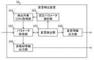
図2は、変更検出装置16を示す。変更検出装置16は、フィールド機器11の設定パラメータの値について変更の有無を検出するものであり、検出対象リスト取得部161と、パラメータ取得部162と、変更検出部163と、変更情報出力部164と、設定パラメータ選択部165と、非検知情報出力部166とを有する。[2. Specific configuration of change detection device]
FIG. 2 shows the
検出対象リスト取得部161は、変更の検出対象とする設定パラメータを指定する検出対象リストを取得する。検出対象リストは、少なくともフィールド機器11の型名と、設定パラメータの識別情報とを項目として含んでよい。検出対象リストは、一例としてフィールド機器11の型名ごとに最大で10個の設定パラメータを含む。検出対象リストは全てのフィールド機器11に対して最大で固定数(一例として10個)の設定パラメータを含んでもよい。この場合、検出対象リスト内の各設定パラメータはそれぞれ異なる型名のフィールド機器11を対象としてもよいし、少なくとも一部の2以上の設定パラメータが同じ型名のフィールド機器11を対象としてもよい。検出対象リストは管理者により作成されてよい。例えば、管理者は、フィールド機器11の保全または起動を行う場合に現場作業者によって設定され得る設定パラメータを含めて検出対象リストを作成してよい。なお、検出対象リストには、型名の代わりに、Device Type(機器の種別(流量計、圧力伝送器等)の識別子)とDevice Revision(機器の仕様等のバージョンの識別子)との組み合わせを含んでもよい。 The detection target
検出対象リスト取得部161は、検出対象リストを変更検出装置16に対する入力操作に応じて取得してもよいし、外部の装置(例えば保全管理装置18)との通信によって取得してもよい。これに加えて、検出対象リスト取得部161は、後述の設定パラメータ選択部165により選択された設定パラメータを該当のフィールド機器11の型名とともに逐次、変更の検出対象に加えること、または既存の検出対象と入れ替えることで検出対象リストを更新してよい。検出対象リスト取得部161は、新たな設定パラメータを検出対象リストに加える場合に、リスト内の設定パラメータの個数を維持してもよいし、増やしてもよい。検出対象リスト取得部161は、検出対象リストをパラメータ取得部162に供給してよい。 The detection target
パラメータ取得部162は、フィールド機器11が有する少なくとも1つの設定パラメータの値を取得する。例えば、パラメータ取得部162は、複数のフィールド機器11が有する複数の設定パラメータのうち、検出対象リストに含まれるそれぞれの設定パラメータの値を取得してよい。パラメータ取得部162は検出対象リストに含まれる各設定パラメータの値を、当該設定パラメータに対応づけられた型名の各フィールド機器11から取得してよい。パラメータ取得部162は、予め定められた時間間隔(一例として1日または1週間)ごとに設定パラメータの値を取得してよい。パラメータ取得部162は、取得した設定パラメータの値を変更検出部163および非検知情報出力部166に供給する。 The
また、パラメータ取得部162は、新たに制御用ネットワーク100に接続された新たなフィールド機器11から、少なくとも機器固有情報および設定パラメータの値を取得してよい。パラメータ取得部162は、予め定められた時間間隔(一例として1日または1週間)ごとに新たなフィールド機器11を検出してよい。例えば、パラメータ取得部162はプラグアンドプレイ機能によって新たなフィールド機器11を検出してよい。パラメータ取得部162は、取得した機器固有情報および設定パラメータの値などを、変更検出部163を介して変更情報出力部164に供給してよい。 Further, the
変更検出部163は、設定パラメータの値が変更されたか否かを検出する。変更検出部163は、変更の有無を変更情報出力部164、パラメータ取得部162および設定パラメータ選択部165に供給してよい。 The
変更情報出力部164は、設定パラメータの値の変更が検出されたことに応じて、変更情報を出力する。例えば、変更情報出力部164は、複数のフィールド機器11のそれぞれについて保全管理装置18へと変更情報を送信してよい。変更情報には、変更が検出されたことを示す情報(フラグ等)があるが、この情報に加えて変更後の設定パラメータの値と、該当するフィールド機器11の機器識別情報とを含んでよい。また、変更情報には、変更が検出された日時を含んでよい。なお、設定パラメータの値の変更が検出されない場合、変更情報出力部164は、変更が検出されていないことを示す情報(フラグ等)を保全管理装置18へ送信してよく、この情報に加えて変更されていない設定パラメータの値と、該当するフィールド機器11の機器識別情報を送信してもよい。 The change
また、変更情報出力部164は、パラメータ取得部162から新たなフィールド機器11の機器固有情報および設定パラメータの値などが供給された場合には、これらを機器台帳1800に登録させる登録要求を保全管理装置18へと送信してよい。 Further, the change
設定パラメータ選択部165は、複数の設定パラメータのそれぞれが変更される頻度に基づいて、変更の検出対象とする設定パラメータを選択する。設定パラメータ選択部165は、選択した設定パラメータを検出対象リスト取得部161に供給して検出対象リストを更新させてよい。 The setting
非検知情報出力部166は、パラメータ取得部162がフィールド機器11を検知できずにフィールド機器11から設定パラメータの値を取得できないことを検出した場合、この検出に応じて、フィールド機器11が非検知であることを示す非検知情報を出力する。設定パラメータの値が取得できない状況は、現場作業者によりフィールド機器11が制御用ネットワーク100から取り外される場合、または、取り外されてはいないがフィールド機器11の不具合等によって通信不良が生じる場合などに発生し得る。非検知情報は、フィールド機器11の機器固有情報を含んでよい。非検知情報出力部166は、非検知情報を保全管理装置18に出力してよい。 When the non-detection
以上の変更検出装置16によれば、保全管理装置18に変更情報を送信するので、複数のフィールド機器11のそれぞれの機器固有情報および設定パラメータの内容を保全管理装置18で一元管理することができる。 According to the above
また、複数のフィールド機器11が有する複数の設定パラメータのうち、検出対象リストに含まれる設定パラメータが変更の検出対象とされるので、全ての設定パラメータの値を取得する場合と比較して、通信される情報量を抑えることができる。これは、運転制御装置13によって制御されるフィールド機器11において、保全に関する設定パラメータの値の通信よりも、制御に用いられるデータの通信の優先度が高く、設定パラメータの値の通信については情報量を抑えることが望まれる場合に特に有効である。また、重要な設定パラメータを検出対象リストに含めることにより、その変更を早期に検出することができる。 Further, among the plurality of setting parameters of the plurality of
また、各設定パラメータの変更頻度に基づいて変更の検出対象とする設定パラメータが選択されるので、例えば実際にプラントでフィールド機器11を稼働して運用している場合において、変更頻度の多い設定パラメータの変更を確実に検出することができる。 Further, since the setting parameter to be detected of the change is selected based on the change frequency of each setting parameter, for example, when the
また、予め定められた時間間隔で設定パラメータの値が取得される。設定パラメータの変更は常時行われものではなく、定期的にまたは必要に応じて行われる保全作業時に実施されるので、予め定められた時間間隔で設定パラメータの値を取得して変更の検出を繰り返すことによって、変更が行われた後になるべく早期に自動的に変更の検出を行うことができる。 In addition, the values of the setting parameters are acquired at predetermined time intervals. Since the setting parameter is not changed all the time, but is carried out regularly or during maintenance work as needed, the value of the setting parameter is acquired at a predetermined time interval and the change is repeatedly detected. As a result, the change can be automatically detected as soon as possible after the change is made.
また、新たに接続された新たなフィールド機器11の機器固有情報および設定パラメータの値が取得されて機器台帳1800に登録されるので、新たに接続されたフィールド機器11についても設定パラメータの値の変更を検出することができるとともに、機器台帳1800に新たなフィールド機器11の情報及び設定パラメータの値の変更を自動で登録できる。
また、現場作業者がフィールド機器11の点検や交換等のために取り外した場合、非検知情報出力部166によって非検知情報が保全管理装置18に出力されるので、現場の状況を管理者と共有できる。Further, since the device-specific information and the value of the setting parameter of the newly connected
Further, when the field worker removes the
[2−1.検出対象リスト]
図3は、検出対象リストを示す。本実施形態では一例として検出対象リストは、フィールド機器11の型名および製品名と、設定パラメータの識別情報と、補足情報とを含む。設定パラメータの識別情報は、フィールド機器11の型名ごとの検出対象の設定パラメータの番号と、設定パラメータを識別するためのコードおよびネームと、設定パラメータの内容の説明文とを含む。補足情報は、設定パラメータの値の変更が検出されることで保全管理システム1のユーザ(一例として現場作業者または管理者)が得られるメリットの説明を含む。なお、設定パラメータの内容の説明文および補足情報は検出対象リストに含まれなくてもよい。[2-1. Detection target list]
FIG. 3 shows a detection target list. In the present embodiment, as an example, the detection target list includes the model name and product name of the
ここで、この図の検出対象リストでは、型名「AAA010」、製品名「差圧圧力伝送器」のフィールド機器11に対してコード「J10」の設定パラメータが変更の検出対象として指定されている。この設定パラメータは調整量を設定するものである。一例としてフィールド機器11は、自動的なゼロ点調整を行って取得された調整量を内部に保存し、センサ測定値から当該調整量を減算した値をプロセス値として運転制御装置13に出力する。調整量は保全用端末12などにより変更され得る。この設定パラメータの値の変更が検出されることで、具体的には、フィールド機器11での自動的なゼロ点調整の実行または保全用端末12による設定パラメータの値の変更などによってゼロ点調整量が変更されたことが検出されることによって、ゼロ調整についての変更の有無および内容が正確に情報共有される。 Here, in the detection target list in this figure, the setting parameter of the code "J10" is specified as the change detection target for the
また、同じフィールド機器11に対しては、コード「S00」の設定パラメータが変更の検出対象として指定されている。この設定パラメータはパラメータの初期化を設定するものであり、値の変更が検出されることで、具体的には初期化が未実行を示す値から、実行済みを示す値への変更が検出されることによって、初期化についての変更の有無および内容が正確に情報共有される。 Further, for the
また、同じフィールド機器11に対しては、コード「C10」の設定パラメータが変更の検出対象として指定されている。この設定パラメータはフィールド機器11に付されるタグ名を設定するものであり、値の変更が検出されることで、タグ名の変更の有無および内容が正確に情報共有される。なお、フィールド機器11を設置したときはタグ名が入力されていない状態(タグ名は空欄)でよく、後日特定のタグ名が入力された場合に、タグ名の変更があったことが検出されてもよい。タグ名は例えばフィールド機器11の用途を識別するための識別子でよく、例えば保全管理システム1の管理者により設定されてよい。 Further, for the
また、同じフィールド機器11に対しては、コード「D23」の設定パラメータが変更の検出対象として指定されている。この設定パラメータはテストの条件を設定するものであり、一例としてテスト出力の出力値を設定する。例えば設定パラメータの値である出力値は0%(4mA)〜100%(20mA)の何れかの値に設定されてよく、値が0%(4mA)から50%(12mA)に変更された場合に運転制御装置13で50%の出力値が受信されるかをテストするのに用いられる。この設定パラメータの値の変更が検出されることで、テストの有無および出力値の変更内容が正確に情報共有される。 Further, for the
また、この図の検出対象リストでは、型名「BBB010」、製品名「電磁流量計」のフィールド機器11に対してコード「B15」の設定パラメータが変更の検出対象として指定されている。この設定パラメータはプロセスデータの算出に使用されるものであり、一例としてダンピング時間を設定するものである。この設定パラメータの値の変更が検出されることで、ダンピング係数の変更の有無および内容が正確に情報共有される。例えば、被測定流体の流量の変動が小さいプロセスであればダンピング時間(例えば一次遅れの時定数)を現在値より大きい値に変更し、流量の変動が大きいプロセスであればダンピング時間を現在値より小さい値に変更する。 Further, in the detection target list in this figure, the setting parameter of the code "B15" is specified as the change detection target for the
なお、設定パラメータの種類はこれらに限らず、例えばセンサであるフィールド機器11に固有の定数でもよい。この設定パラメータの値の変更が検出されることで、プロセス値の測定条件などの変更の有無および内容が正確に情報共有される。また、検出対象リストは、設定パラメータについての情報を並べたものであれば他の形式でもよく、必ずしもリスト型のデータ構造でなくてもよい。例えば、検出対象リストは、型名とコードとが対応付けられて配列された形式でもよい。 The type of setting parameter is not limited to these, and may be, for example, a constant unique to the
[3.保全管理装置の具体的な構成]
図4は、保全管理装置18を示す。保全管理装置18は、記憶部180と、変更情報受信部181と、保全作業推定部182と、登録要求受信部183と、機器登録部184と、検索部185と、ドキュメント追加部186とを有してよい。但し、保全作業推定部182は保全管理装置18に具備されなくてもよい。[3. Specific configuration of maintenance management equipment]
FIG. 4 shows the
記憶部180は、機器台帳1800を記憶する。機器台帳1800は、各フィールド機器11の機器固有情報に対応付けて、設定パラメータの値の履歴を記憶してよい。これに代えて、機器台帳1800は、各機器固有情報に対応付けて最新の設定パラメータの値のみを記憶してもよい。 The
変更情報受信部181は、変更情報出力部164から出力される変更情報を受信する。変更情報受信部181は、受信した変更情報に応じて機器台帳1800を更新してよい。更新は、設定パラメータの値を変更された値で書き換えることでもよいし、変更された値を履歴として保存することでもよく、変更日時を書き換えることを含んでもよい。また、変更情報受信部181は、受信した変更情報を保全作業推定部182に供給してよい。これによって、設定パラメータの値が変更された場合、変更後の情報で機器台帳1800を自動で更新できる。 The change
また、変更情報受信部181は、非検知情報出力部166から出力される非検知情報を受信してよい。変更情報受信部181は、受信した非検知情報に応じて機器台帳1800を更新してよい。例えば、変更情報受信部181は、非検知情報の機器固有情報を機器台帳1800で検出し、当該機器固有情報に対応付けて、フィールド機器11が制御用ネットワーク100上で非検知であることを記録してよい。 Further, the change
保全作業推定部182は、設定パラメータの値が変更されたことに応じ、フィールド機器11に対して実施された保全作業を推定する。保全作業推定部182は、設定パラメータと、当該設定パラメータの値が変更された場合にフィールド機器11に対して実施されたはずの保全作業とを対応付けた推定ルールを用いて推定を行ってよい。設定ルールは過去の保全記録と設定パラメータの変更履歴とを解析することで管理者により作成され、適宜更新されてよい。保全作業推定部182は、変更情報受信部181からの変更情報に含まれる設定パラメータに対して推定ルールで対応付けられた保全作業を、フィールド機器11に行われた保全作業として推定してよい。保全作業推定部182は、推定した保全作業の情報を保全管理装置18の表示装置(図示せず)に表示させてよい。 The maintenance
登録要求受信部183は、変更情報出力部164から出力される登録要求を受信する。登録要求受信部183は、受信した登録要求を機器登録部184および検索部185に供給してよい。 The registration
機器登録部184は、登録要求を受信したことに応じて、新たなフィールド機器11を機器台帳1800に登録する。例えば、機器登録部184は、登録要求に含まれる機器固有情報および設定パラメータの値を対応付けて機器台帳1800に登録する。これによって、登録要求が受信された場合、新たなフィールド機器11の情報を自動で登録できる。 The
検索部185は、フィールド機器11の機器固有情報を用いて、当該フィールド機器11に関するドキュメントをいずれかのドキュメントデータベース17から検索する。ドキュメントが検索されるフィールド機器11は新たに制御用ネットワーク100に接続されたフィールド機器11でもよいし、既に接続されて機器台帳1800に登録されているフィールド機器11でもよい。検索部185は、検索してドキュメントデータベース17から取得したドキュメントをドキュメント追加部186に供給してよい。 The
ドキュメント追加部186は、検索部185が検索してドキュメントデータベース17から取得したドキュメントを、フィールド機器11に対応付けて機器台帳1800に追加する。これにより、新たなフィールド機器11に関する紙媒体のドキュメントを見つける必要がなくなるため、ドキュメントの確認、ひいてはメンテナンスを容易化することができる。 The
[3−1.機器台帳]
図5は、機器台帳1800を示す。本実施形態では一例として機器台帳1800は、フィールド機器11の機器固有情報と、設定パラメータの値と、スペック情報と、ドキュメント番号とを項目として含む。機器固有情報は、通信プロトコルによって付与されたシリアル番号である機器IDと、フィールド機器11の製造業者により設定されたシリアル番号、型名、製造業者名、製品名と、管理者により設定されたタグ名とを項目として含む。なお、機器台帳1800には、フィールド機器11の現在のステータス、設置位置、機能的な役割(例えばAnalog Input、Analog Output等)、材料名などの項目が含まれてもよい。設定パラメータは、フィールド機器11が有する各設定パラメータの設定値の履歴を含む。スペック情報は、フィールド機器11の仕様を含む。ドキュメント番号は、フィールド機器11に関するドキュメントの番号を示す。例えば、ドキュメント番号は保全管理装置18の内部に記憶されたドキュメントのファイル名でよく、ドキュメントの保存先(URL名等)とドキュメントのファイル名との組み合わせでもよい。[3-1. Equipment ledger]
FIG. 5 shows the
[3−2.推定ルール]
図6は、推定ルールを示す。推定ルールは、設定パラメータと、当該設定パラメータの値が変更された場合にフィールド機器11に対して実施されたはずの保全作業とを対応付ける。例えば、この図の推定ルールでは、ダンピング時間を設定するための「DAMPING」の設定パラメータに対し、「チューニング」の保全作業が対応付けられている。例えば、チューニングは、被測定流体の流量の変動の大きさに応じてダンピング時間を変更して流量の状態に適合させることでよい。なお、1つの設定パラメータに対して対応付けられる保全作業は1つでもよいし、複数でもよい。現場作業者が新たなフィールド機器11を設置する場合、設置作業に加えて、フィールド機器11の出庫作業や在庫リストの更新等の付随的な作業を行う場合がある。保全作業には、このような付随的な作業も含まれてよい。[3-2. Estimating rule]
FIG. 6 shows an estimation rule. The estimation rule associates the setting parameter with the maintenance work that should have been performed on the
[4.保全管理システムの動作]
[4−1.設定パラメータが変更された場合の動作]
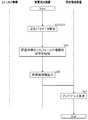
図7は、フィールド機器11の設定パラメータの値が変更された場合の保全管理システム1の動作を示す。保全管理システム1は、ステップS11〜S31の処理を行うことにより設定パラメータの値の変更を機器台帳1800に登録する。一例として、この動作は予め定められた時間間隔ごとに行われてよい。[4. Operation of maintenance management system]
[4-1. Operation when the setting parameter is changed]
FIG. 7 shows the operation of the
まずステップS11において変更検出装置16のパラメータ取得部162は、フィールド機器11に対して設定パラメータの値を要求する。例えば、パラメータ取得部162は、検出対象リストに含まれる複数の設定パラメータについての各設定値を、当該設定パラメータに対応付けられた型名の各フィールド機器11に対して要求する。一例として、変更検出装置16の内部には、フィールド機器11の型名と、通信プロトコルにより各フィールド機器11に付与されたシリアル番号とを対応付けたテーブルが記憶されてよく、パラメータ取得部162は当該テーブルを参照して該当のフィールド機器11に設定パラメータの値を要求してよい。 First, in step S11, the
次に、ステップS13において設定パラメータの値を要求された各フィールド機器11は、要求された設定パラメータの値を変更検出装置16に送信する。フィールド機器11は、自身の機器固有情報と対応付けて設定パラメータの値を送信してよい。フィールド機器11は、運転制御装置13を介して設定パラメータの値を変更検出装置16に送信してよい。 Next, each
次に、ステップS15において変更検出装置16のパラメータ取得部162は、フィールド機器11から機器固有情報と、設定パラメータの値とを取得する。パラメータ取得部162は、ステップS11が実行されてから基準時間(一例として1分間)内に、機器固有情報および設定パラメータの値を取得してよい。 Next, in step S15, the
次に、ステップS17において変更検出装置16の変更検出部163は、設定パラメータの値が変更されたか否かを検出する。例えば、変更検出部163は、新たに取得(例えば今回取得)された設定パラメータの値が、以前に取得(例えば今回より1つ前に取得)された設定パラメータの値と同一でないことに応じて、設定パラメータの値が変更されたことを検出してよい。変更検出部163は、フィールド機器11ごと、つまり機器固有情報ごとに設定パラメータの値が変更されたか否かを検出してよい。変更検出装置16の内部には、パラメータ取得部162によって取得された少なくとも前回の設定パラメータの値(本実施形態においては一例として過去に取得された各回の設定パラメータの値の履歴)が記憶されてよく、変更検出部163は、この記憶内容を変更の検出に用いてよい。なお、本実施形態では、取得された複数の設定パラメータの値のうち、いずれかの値が変更された場合について説明する。取得した複数の設定パラメータの値のいずれにも変更がない場合には、保全管理システム1はステップS19以降の動作を行わずに処理を終了してもよいし、変更が検出されていないことを示す情報と機器固有情報とを保全管理装置18に送信して処理を終了してもよい。 Next, in step S17, the
次に、ステップS19においてパラメータ取得部162は、設定パラメータの値の変更が検出されたことに応じ、フィールド機器11に対し、検出対象リスト内のいずれかの設定パラメータに関連づけられた関連設定パラメータの値を要求する。例えば、パラメータ取得部162は、一の設定パラメータの値の変更が検出されたことに応じて、当該一の設定パラメータに関連付けられた関連設定パラメータの値を要求してよい。関連設定パラメータは、一の設定パラメータと合わせて変更され得る設定パラメータでよい。一例として、一の設定パラメータがセンサとしてのフィールド機器11の測定範囲の上限値である場合には、関連設定パラメータは測定範囲の下限値でよい。関連設定パラメータは、一の設定パラメータと同じ型名のフィールド機器11に対する他の設定パラメータでもよいし、一の設定パラメータと異なる型名のフィールド機器11に対する設定パラメータでもよい。パラメータ取得部162は、少なくとも1つの設定パラメータ(一例として検出対象リスト内の各設定パラメータ)と、その関連設定パラメータと、関連設定パラメータを有するフィールド機器11の型名とを対応付けたテーブルを保持してよく、当該テーブルを参照して関連設定パラメータの値の要求を、該当のフィールド機器11に送信してよい。 Next, in step S19, the
これに加えて、またはこれに代えて、パラメータ取得部162は、検出対象リスト内のいずれかの設定パラメータの値の変更が検出されたことに応じて、検出対象リスト内に含まれない複数の設定パラメータ(対象外設定パラメータとも称する)の値を要求する。例えば、パラメータ取得部162は、検出対象リスト内の少なくとも1つの設定パラメータの変更が検出されたことに応じて、各フィールド機器11の各設定パラメータの値、つまり各フィールド機器11が有する全ての設定パラメータの値を要求してよい。 In addition to or instead of this, the
次に、ステップS21において設定パラメータの値を要求されたフィールド機器11は、ステップS13と同様にして、要求された設定パラメータの値を変更検出装置16に送信する。 Next, the
次に、ステップS23において変更検出装置16のパラメータ取得部162は、フィールド機器11から機器固有情報と、関連設定パラメータの値または対象外設定パラメータの値とを取得する。パラメータ取得部162は、ステップS19が実行されてから基準時間内に、機器固有情報と、関連設定パラメータの値または対象外設定パラメータの値とを取得してよい。 Next, in step S23, the
次に、ステップS25において変更検出装置16の変更検出部163は、上述のステップS17と同様にして、関連設定パラメータの値または対象外設定パラメータの値が変更されたか否かを検出する。 Next, in step S25, the
また、設定パラメータ選択部165は、各設定パラメータの変更頻度に基づいて、変更の検出対象とする設定パラメータを選択し、検出対象リスト取得部161内の検出対象リストを更新する。例えば、設定パラメータ選択部165は、検出対象リスト内の設定パラメータと、関連設定パラメータまたは対象外設定パラメータとの変更頻度に基づいて設定パラメータを選択してよい。一例として、設定パラメータ選択部165は、変更検出部163の検出結果に基づいて変更頻度を算出して、変更頻度を設定パラメータと関連付けることによって、フィールド機器11の型名ごとに複数の選択パラメータのうち、変更の頻度が基準順位よりも上位の設定パラメータを選択してよい。また、設定パラメータ選択部165は、一の設定パラメータの変更の頻度が基準頻度よりも大きい場合に、当該一の設定パラメータを選択してもよい。設定パラメータ選択部165は、選択した設定パラメータを検出対象リストに追加、又は検出対象パラメータの個数が制限されている場合には、変更頻度の少ない設定パラメータを変更頻度の多い設定パラメータに変更してもよい。これによって、フィールド機器11の稼働前に管理者によって検出対象リストを設定して運用を開始し、運用状態によって検出対象リストに含まれない設定パラメータの変更頻度が多ければ当該設定パラメータを検出対象リストに含めることで、フィールド機器11の運用に即して検出対象リストを更新し、リスト内の設定パラメータの値の変更の検出をすることができる。 Further, the setting
なお、検出対象リストの更新はステップS25の処理で毎回行われなくてもよく、予め定められた時間間隔(例えば3カ月)ごとに行われてよい。また、保全管理システム1は、ステップS19〜S25の処理を行わなくてもよい。 The detection target list does not have to be updated every time in the process of step S25, and may be updated at predetermined time intervals (for example, 3 months). Further, the
次に、ステップS27において変更情報出力部164は、変更情報を出力する。変更情報出力部164は、パラメータ取得部162が関連設定パラメータの値を取得した場合には、当該関連設定パラメータの値を含む変更情報を出力してよい。変更情報出力部164は、パラメータ取得部162が対象外設定パラメータの値を取得した場合には、当該対象外設定パラメータの値を含む変更情報を出力してよい。 Next, in step S27, the change
次に、ステップS29において保全管理装置18の変更情報受信部181は、変更情報を受信して機器台帳1800を更新する。変更情報受信部181は、更新前後の設定パラメータの値を機器固有情報と共に保全管理装置18の表示装置に表示させてもよい。 Next, in step S29, the change
そして、ステップS31において保全作業推定部182は、変更情報に含まれる設定パラメータに対して推定ルールで対応付けられた保全作業を、フィールド機器11に行われた保全作業として推定し保全管理装置18の表示装置に表示させる。これにより、フィールド機器11に行われた保全作業について管理者および現場作業者などの間で情報共有することができる。 Then, in step S31, the maintenance
以上の動作によれば、変更の検出対象とする設定パラメータの値の変更が検出されたことに応じて関連設定パラメータの値が更に取得され、関連設定パラメータの値を含む変更情報が出力されるので、検出対象の設定パラメータに加えて関連設定パラメータの値を毎回取得する場合と比較して、通信される情報量を抑えつつ、関連設定パラメータの値の変更も合わせて検出することができる。また、測定対象のプロセスによっては、測定範囲の上限値及び下限値は互いに連動していて、一方の設定パラメータの値(上限値)を変更したら他方の設定パラメータの値(下限値)も変更することがある。このような場合に、一方の設定パラメータと関連する他方の設定パラメータの値も連動して取得し、変更を検出することができる。 According to the above operation, the value of the related setting parameter is further acquired according to the change of the value of the setting parameter for which the change is detected is detected, and the change information including the value of the related setting parameter is output. Therefore, as compared with the case where the value of the related setting parameter is acquired every time in addition to the setting parameter to be detected, it is possible to detect the change of the value of the related setting parameter while suppressing the amount of information to be communicated. In addition, depending on the process to be measured, the upper limit value and the lower limit value of the measurement range are linked to each other, and if the value (upper limit value) of one setting parameter is changed, the value (lower limit value) of the other setting parameter is also changed. Sometimes. In such a case, the value of one setting parameter and the value of the other setting parameter related to it can be acquired in conjunction with each other, and the change can be detected.
また、変更の検出対象とするいずれかの設定パラメータの値の変更が検出されたことに応じて対象外設定パラメータの値が更に取得され、対象外設定パラメータの値を含む変更情報が出力されるので、全ての設定パラメータの値を毎回取得する場合と比較して、通信される情報量を抑えつつ、対象外設定パラメータの値の変更も合わせて検出することができる。これによって、検出対象のパラメータが変更されたことに応じて他の設定パラメータ(対象外設定パラメータ)も確認して各設定パラメータの値を詳細に確認したい場合に、自動で他の設定パラメータの値を取得し、変更を検出することができる。 In addition, the value of the non-target setting parameter is further acquired according to the change of the value of any of the setting parameters to be detected, and the change information including the value of the non-target setting parameter is output. Therefore, as compared with the case where the values of all the setting parameters are acquired each time, it is possible to detect changes in the values of the non-target setting parameters while suppressing the amount of information to be communicated. As a result, when you want to check other setting parameters (non-target setting parameters) in detail according to the change of the detection target parameter and check the value of each setting parameter in detail, the value of the other setting parameter is automatically set. Can be obtained and changes can be detected.
[4−2.フィールド機器を検知できない場合の動作]
図8は、制御用ネットワーク100上でフィールド機器11が検知できない場合の保全管理システム1の動作を示す。保全管理システム1は、ステップS43〜S47の処理を行うことにより非検知のフィールド機器11を機器台帳1800に登録する。一例として、この動作は上述のステップS11およびステップS19の少なくとも一方での設定パラメータの値の要求に対し、応答が取得できない場合に行われる。[4-2. Operation when field equipment cannot be detected]
FIG. 8 shows the operation of the
まず、ステップS43においてパラメータ取得部162は、上述のステップS11,ステップS19の処理が実行されてから基準時間内に応答が取得されなかったフィールド機器11が存在することを検知する。 First, in step S43, the
次に、ステップS45において非検知情報出力部166は、パラメータ取得部162から非検知であったフィールド機器11の機器固有情報を取得して、そのフィールド機器11が非検知であることを示す非検知情報を保全管理装置18へ出力する。例えば、非検知情報出力部166は、ステップS11,ステップS19で設定パラメータの値を要求したフィールド機器11の機器固有情報のうち、応答のなかったフィールド機器11の機器固有情報を非検知情報に含めてよい。 Next, in step S45, the non-detection
次に、ステップS47において保全管理装置18の変更情報受信部181は非検知情報を受信して、非検知であったフィールド機器11に対するメンテナンスを促すメッセージを保全管理装置18および保全用端末12の少なくとも一方の表示装置に表示させる。例えば、変更情報受信部181は、非検知であったフィールド機器11の機器固有情報と、当該フィールド機器11が取り外されているか、又はフィールド機器11の不具合によって通信不良が生じているかの点検を促すメッセージを表示させてよい。 Next, in step S47, the change
これに加えて、またはこれに代えて、変更情報受信部181は、受信した非検知情報に応じて機器台帳1800を更新してよい。例えば、変更情報受信部181は、非検知情報の機器固有情報を機器台帳1800で検出し、当該機器固有情報に対応付けて、フィールド機器11が制御用ネットワーク100上で非検知であることを機器台帳1800に記録してよい。 In addition to or instead of this, the change
以上の動作によれば、設定パラメータの値を取得できないことに応じて非検知情報が出力されるので、フィールド機器11の故障を早期に検出することができる。また、メンテナンスのためにフィールド機器11が停止されたことを管理者と現場作業者との間で確実に共有することができる。従って、フィールド機器11の運転制御、保全などを適切に行うことができる。 According to the above operation, the non-detection information is output in response to the inability to acquire the value of the setting parameter, so that the failure of the
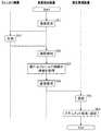
[4−3.フィールド機器が新たに接続された場合の動作]
図9は、新たにフィールド機器11が制御用ネットワーク100に接続された場合の保全管理システム1の動作を示す。保全管理システム1は、ステップS51〜S63の処理を行うことにより新たなフィールド機器11を機器台帳1800に登録する。一例として、この動作は予め定められた時間間隔ごとに行われてよい。これに加えて、またはこれに代えて、この動作は新たにフィールド機器11が設置されたという報告を受けた管理者の操作に応じて行われてもよく、例えば図7に示す動作の実行中に行われてもよい。[4-3. Operation when a field device is newly connected]
FIG. 9 shows the operation of the
まずステップS51において変更検出装置16のパラメータ取得部162は、各フィールド機器11に対して通信を要求する。例えばパラメータ取得部162は、管理者の操作に応じてプラグアンドプレイ機能を実行し、新たに接続されたフィールド機器11を含む各フィールド機器11に通信を要求してよい。これに加えて、またはこれに代えて、パラメータ取得部162は予め定められた時間間隔ごとにプラグアンドプレイ機能を実行して通信を要求してもよい。 First, in step S51, the
次に、ステップS53において各フィールド機器11はパラメータ取得部162に応答を送信する。この応答にはフィールド機器11の機器固有情報(一例として型名、および、通信プロトコルによりフィールド機器11に付与されたシリアル番号)と、当該フィールド機器11の設定パラメータの値とが含まれてよい。 Next, in step S53, each
次に、ステップS55において変更検出装置16のパラメータ取得部162は、フィールド機器11との通信を検知する。パラメータ取得部162は、検知した通信からフィールド機器11の機器固有情報および設定パラメータの値を取得してよい。 Next, in step S55, the
次に、ステップS57においてパラメータ取得部162は、新たなフィールド機器11の機器固有情報および設定パラメータの値を取得する。例えば、パラメータ取得部162は、ステップS55の処理を前回行ったときに取得した機器固有情報と、今回行ったときに取得した機器固有情報とを比較して今回新たに接続されて取得された機器固有情報を検出し、この新たな機器固有情報に対応付けられた設定パラメータの値を取得してよい。なお、新たな機器固有情報が検出された場合には、パラメータ取得部162とフィールド機器11との通信により、変更検出装置16の内部においてフィールド機器11の型名と、通信プロトコルにより各フィールド機器11に付与されたシリアル番号とを対応付けたテーブルが更新されてよい。これにより、上述のステップS11,S19で新たなフィールド機器11に対しても設定パラメータの値が要求される。 Next, in step S57, the
次に、ステップS59において変更検出装置16の変更情報出力部164は、新たなフィールド機器11の機器固有情報および設定パラメータの値を機器台帳1800に登録させる登録要求を出力する。 Next, in step S59, the change
次に、ステップS61において保全管理装置18の機器登録部184は、登録要求に含まれる機器固有情報および設定パラメータの値を対応付けて機器台帳1800に登録する。 Next, in step S61, the
そして、ステップS63において検索部185は、新たなフィールド機器11の機器固有情報を用いて、当該フィールド機器11に関するドキュメントをドキュメントデータベース17から検索する。例えば、検索部185は、登録要求受信部183から受信した登録要求内の機器固有情報に含まれる型名を検索キーとして、当該型名に対応付けられたドキュメントを各ドキュメントデータベース17内で検索してよい。ドキュメントが検索された場合には、ドキュメント追加部186は、当該ドキュメントをフィールド機器11に対応付けて機器台帳1800に追加する。例えば、ドキュメント追加部186は、機器登録部184によって登録された機器固有情報および設定パラメータの値に対応付けて、検索したドキュメントを機器台帳1800に登録してよい。 Then, in step S63, the
[5.表示画面]
図10は、保全管理装置18の表示画面の一例を示す。保全管理装置18には、フィールド機器11のリストが表示部(不図示)に表示されてよい。このリストには、機器台帳1800の少なくとも一部の情報が含まれてよい。保全管理装置18の制御部(不図示)は、機器台帳1800内の情報(例えば変更情報受信部181によって受信されて更新された情報)に基づいて、フィールド機器11のリストを生成して表示部に表示する。更に、各行に示されるフィールド機器11のうち、設定パラメータの値が変更されたフィールド機器11の情報、および、制御用ネットワーク100上で非検知であったフィールド機器11の情報の少なくとも一方は表示態様が変更されて表示部に識別表示されてよい。本実施形態においては一例として、設定パラメータの値が変更されたフィールド機器11の情報は太字(シリアル番号91RC55555)で表示され、非検知であったフィールド機器11の情報は網掛け(シリアル番号91RE77777)で表示される。これによって、管理者は、フィールド機器11のリストで機器の一覧を確認でき、この中で変更のあったフィールド機器11を容易に識別できるので、正確に情報共有することができる。[5. Display screen]
FIG. 10 shows an example of the display screen of the
図11は、保全管理装置18の表示画面の他の例を示す。図10の状態からいずれかの行のフィールド機器11が保全管理装置18の入力部(不図示)を介して選択された場合には、保全管理装置18の制御部は、選択に応じて機器台帳1800又は必要に応じて外部データベースからフィールド機器11の詳細情報を取得して、選択されたフィールド機器11の詳細情報を表示部に表示してよい。詳細情報には、選択されたフィールド機器11についての機器台帳1800の内容、および、設定パラメータの値の履歴が含まれてよい。図中の設定パラメータの履歴では、下側の3行の設定パラメータの値が変更されたことが示されている。これによって、管理者は、フィールド機器11の詳細情報及び詳細な設定パラメータの履歴の一覧を確認できるので、詳細な情報についても正確に共有することができる。 FIG. 11 shows another example of the display screen of the
この表示画面には、管理者の操作に応じてフィールド機器11の製品情報およびドキュメント等が択一的に表示されてよい。製品情報には、フィールド機器11の製造日、通信プロトコルなどが含まれてよく、ドキュメントには、機器台帳1800に登録されたドキュメントの情報が含まれてよい。 The product information, documents, and the like of the
[6.変形例]
なお、上記の実施形態では、検出対象リストは、フィールド機器11の型名と設定パラメータの識別情報とを含むこととして説明したが、フィールド機器11の型名に代えて機器固有情報を含んでもよい。この場合には、変更検出装置16のパラメータ取得部162は検出対象リストに含まれる設定パラメータの値を、当該設定パラメータに対応付けられた機器固有情報のフィールド機器11から取得してよい。[6. Modification example]
In the above embodiment, the detection target list has been described as including the model name of the
また、パラメータ取得部162がプラグアンドプレイ機能を有することとして説明したが、資源管理装置15または保全管理装置18が有することとしてもよい。この場合には、パラメータ取得部162は、資源管理装置15または保全管理装置18がプラグアンドプレイ機能によってステップS51,S55,S57の処理により取得して変更検出装置16に供給した機器固有情報を用いて、新たなフィールド機器11の機器固有情報を取得してよい。 Further, although the
また、検出対象リストは管理者により作成されることとして説明したが、パラメータ取得部162、変更検出部163および設定パラメータ選択部165により作成されてもよい。例えば、予め定められた期間(一例として1カ月)の間にパラメータ取得部162および変更検出部163は各フィールド機器11の各設定パラメータ(例えば全ての設定パラメータ)を取得して変更の有無を検出してよい。そして、設定パラメータ選択部165は、変更の有無の検出結果に基づいて各設定パラメータの変更頻度を算出して、この期間内での変更頻度に基づいて選択される設定パラメータを変更の検出対象に含めることで検出対象リストを生成してもよい。検出対象リストの生成は予め定められた期間(一例として3カ月)ごとに行われてよい。例えば、設定パラメータ選択部165は、変更頻度の多い上位の設定パラメータのうち、予め定められた個数の設定パラメータを変更の検出対象として変更検出リストを生成する。 Further, although the detection target list has been described as being created by the administrator, it may be created by the
また、パラメータ取得部162は各フィールド機器11の各設定パラメータのうち検出対象リストに含まれる設定パラメータの値をフィールド機器11から取得することとして説明したが、各フィールド機器11から各設定パラメータの値を取得してもよい。例えば、パラメータ取得部162は、ステップS11の処理において各フィールド機器11の全ての設定パラメータの値を取得してよい。 Further, although the
また、保全管理システム1は保全用端末12と、運転制御装置13と、インタフェース装置14と、資源管理装置15と、1または複数のドキュメントデータベース17とを備えることとして説明したが、これらのいずれかを備えないこととしてもよい。また、変更検出装置16は検出対象リスト取得部161と、設定パラメータ選択部165と、非検知情報出力部166とを備えることとして説明したが、これらのいずれかを備えないこととしてもよい。また、変更検出装置16及び保全管理装置18は、それぞれ1つの装置で実現されてもよく、複数の装置の組み合わせで実現されてもよいし、変更検出装置16及び保全管理装置18が、一体化した装置で実現されてもよい。 Further, although the
また、本発明の様々な実施形態は、フローチャートおよびブロック図を参照して記載されてよく、ここにおいてブロックは、(1)操作が実行されるプロセスの段階または(2)操作を実行する役割を持つ装置のセクションを表わしてよい。特定の段階およびセクションが、専用回路、コンピュータ可読媒体上に格納されるコンピュータ可読命令と共に供給されるプログラマブル回路、およびコンピュータ可読媒体上に格納されるコンピュータ可読命令と共に供給されるプロセッサの少なくとも1つによって実装されてよい。専用回路は、デジタルおよびアナログの少なくとも一方のハードウェア回路を含んでよく、集積回路(IC)およびディスクリート回路の少なくとも一方を含んでよい。プログラマブル回路は、論理AND、論理OR、論理XOR、論理NAND、論理NOR、および他の論理操作、フリップフロップ、レジスタ、フィールドプログラマブルゲートアレイ(FPGA)、プログラマブルロジックアレイ(PLA)等のようなメモリ要素等を含む、再構成可能なハードウェア回路を含んでよい。 In addition, various embodiments of the present invention may be described with reference to flowcharts and block diagrams, wherein the block serves (1) the stage of the process in which the operation is performed or (2) the role of performing the operation. It may represent a section of the device it has. A particular stage and section is provided by at least one of a dedicated circuit, a programmable circuit supplied with computer-readable instructions stored on a computer-readable medium, and a processor supplied with computer-readable instructions stored on a computer-readable medium. It may be implemented. Dedicated circuits may include at least one of digital and analog hardware circuits, and may include at least one of integrated circuits (ICs) and discrete circuits. Programmable circuits are memory elements such as logical AND, logical OR, logical XOR, logical NAND, logical NOR, and other logical operations, flip-flops, registers, field programmable gate arrays (FPGA), programmable logic arrays (PLA), etc. May include reconfigurable hardware circuits, including.
コンピュータ可読媒体は、適切なデバイスによって実行される命令を格納可能な任意の有形なデバイスを含んでよく、その結果、そこに格納される命令を有するコンピュータ可読媒体は、フローチャートまたはブロック図で指定された操作を実行するための手段を作成すべく実行され得る命令を含む、製品を備えることになる。コンピュータ可読媒体の例としては、電子記憶媒体、磁気記憶媒体、光記憶媒体、電磁記憶媒体、半導体記憶媒体等が含まれてよい。コンピュータ可読媒体のより具体的な例としては、フロッピー(登録商標)ディスク、ディスケット、ハードディスク、ランダムアクセスメモリ(RAM)、リードオンリメモリ(ROM)、消去可能プログラマブルリードオンリメモリ(EPROMまたはフラッシュメモリ)、電気的消去可能プログラマブルリードオンリメモリ(EEPROM)、静的ランダムアクセスメモリ(SRAM)、コンパクトディスクリードオンリメモリ(CD-ROM)、デジタル多用途ディスク(DVD)、ブルーレイ(RTM)ディスク、メモリスティック、集積回路カード等が含まれてよい。 The computer readable medium may include any tangible device capable of storing instructions executed by the appropriate device, so that the computer readable medium having the instructions stored therein is specified in a flowchart or block diagram. The product will be equipped with instructions that can be executed to create a means for performing the operation. Examples of computer-readable media may include electronic storage media, magnetic storage media, optical storage media, electromagnetic storage media, semiconductor storage media, and the like. More specific examples of computer-readable media include floppy (registered trademark) disks, diskettes, hard disks, random access memory (RAM), read-only memory (ROM), erasable programmable read-only memory (EPROM or flash memory), Electrically erasable programmable read-only memory (EEPROM), static random access memory (SRAM), compact disk read-only memory (CD-ROM), digital versatile disk (DVD), Blu-ray (RTM) disk, memory stick, integrated A circuit card or the like may be included.
コンピュータ可読命令は、アセンブラ命令、命令セットアーキテクチャ(ISA)命令、マシン命令、マシン依存命令、マイクロコード、ファームウェア命令、状態設定データ、またはSmalltalk、JAVA(登録商標)、C++等のようなオブジェクト指向プログラミング言語、および「C」プログラミング言語または同様のプログラミング言語のような従来の手続型プログラミング言語を含む、1または複数のプログラミング言語の任意の組み合わせで記述されたコードまたはオブジェクトコードのいずれかを含んでよい。 Computer-readable instructions are assembler instructions, instruction set architecture (ISA) instructions, machine instructions, machine-dependent instructions, microcode, firmware instructions, state-setting data, or object-oriented programming such as Smalltalk, JAVA®, C ++, etc. It may contain either code or object code written in any combination of one or more programming languages, including languages and traditional procedural programming languages such as the "C" programming language or similar programming languages. ..
コンピュータ可読命令は、汎用コンピュータ、特殊目的のコンピュータ、若しくは他のプログラム可能なデータ処理装置のプロセッサまたはプログラマブル回路に対し、ローカルにまたはローカルエリアネットワーク(LAN)、インターネット等のようなワイドエリアネットワーク(WAN)を介して提供され、フローチャートまたはブロック図で指定された操作を実行するための手段を作成すべく、コンピュータ可読命令を実行してよい。プロセッサの例としては、コンピュータプロセッサ、処理ユニット、マイクロプロセッサ、デジタル信号プロセッサ、コントローラ、マイクロコントローラ等を含む。 Computer-readable instructions are applied locally or to a processor or programmable circuit of a general purpose computer, special purpose computer, or other programmable data processing device, or to a wide area network (WAN) such as the local area network (LAN), the Internet, etc. ) May be executed to create a means for performing the operation specified in the flowchart or block diagram. Examples of processors include computer processors, processing units, microprocessors, digital signal processors, controllers, microcontrollers and the like.
図12は、本発明の複数の態様が全体的または部分的に具現化されてよいコンピュータ2200の例を示す。コンピュータ2200にインストールされたプログラムは、コンピュータ2200に、本発明の実施形態に係る装置に関連付けられる操作または当該装置の1または複数のセクションとして機能させることができ、または当該操作または当該1または複数のセクションを実行させることができ、これに加えて、またはこれに代えて、コンピュータ2200に、本発明の実施形態に係るプロセスまたは当該プロセスの段階を実行させることができる。そのようなプログラムは、コンピュータ2200に、本明細書に記載のフローチャートおよびブロック図のブロックのうちのいくつかまたはすべてに関連付けられた特定の操作を実行させるべく、CPU2212によって実行されてよい。 FIG. 12 shows an example of a
本実施形態によるコンピュータ2200は、CPU2212、RAM2214、グラフィックコントローラ2216、およびディスプレイデバイス2218を含み、それらはホストコントローラ2210によって相互に接続されている。コンピュータ2200はまた、通信インタフェース2222、ハードディスクドライブ2224、DVD−ROMドライブ2226、およびICカードドライブのような入出力ユニットを含み、それらは入出力コントローラ2220を介してホストコントローラ2210に接続されている。コンピュータはまた、ROM2230およびキーボード2242のようなレガシの入出力ユニットを含み、それらは入出力チップ2240を介して入出力コントローラ2220に接続されている。 The
CPU2212は、ROM2230およびRAM2214内に格納されたプログラムに従い動作し、それにより各ユニットを制御する。グラフィックコントローラ2216は、RAM2214内に提供されるフレームバッファ等またはそれ自体の中にCPU2212によって生成されたイメージデータを取得し、イメージデータがディスプレイデバイス2218上に表示されるようにする。 The
通信インタフェース2222は、ネットワークを介して他の電子デバイスと通信する。ハードディスクドライブ2224は、コンピュータ2200内のCPU2212によって使用されるプログラムおよびデータを格納する。DVD−ROMドライブ2226は、プログラムまたはデータをDVD−ROM2201から読み取り、ハードディスクドライブ2224にRAM2214を介してプログラムまたはデータを提供する。ICカードドライブは、プログラムおよびデータをICカードから読み取り、これに加えて、またはこれに代えてプログラムおよびデータをICカードに書き込む。 The
ROM2230はその中に、アクティブ化時にコンピュータ2200によって実行されるブートプログラム等、およびコンピュータ2200のハードウェアに依存するプログラムの少なくとも1つを格納する。入出力チップ2240はまた、様々な入出力ユニットをパラレルポート、シリアルポート、キーボードポート、マウスポート等を介して、入出力コントローラ2220に接続してよい。 The
プログラムが、DVD−ROM2201またはICカードのようなコンピュータ可読媒体によって提供される。プログラムは、コンピュータ可読媒体から読み取られ、コンピュータ可読媒体の例でもあるハードディスクドライブ2224、RAM2214、またはROM2230にインストールされ、CPU2212によって実行される。これらのプログラム内に記述される情報処理は、コンピュータ2200に読み取られ、プログラムと、上記様々なタイプのハードウェアリソースとの間の連携をもたらす。装置または方法が、コンピュータ2200の使用に従い情報の操作または処理を実現することによって構成されてよい。 The program is provided by a computer-readable medium such as a DVD-
例えば、通信がコンピュータ2200および外部デバイス間で実行される場合、CPU2212は、RAM2214にロードされた通信プログラムを実行し、通信プログラムに記述された処理に基づいて、通信インタフェース2222に対し、通信処理を命令してよい。通信インタフェース2222は、CPU2212の制御下、RAM2214、ハードディスクドライブ2224、DVD−ROM2201、またはICカードのような記録媒体内に提供される送信バッファ処理領域に格納された送信データを読み取り、読み取られた送信データをネットワークに送信し、またはネットワークから受信された受信データを記録媒体上に提供される受信バッファ処理領域等に書き込む。 For example, when communication is executed between the
また、CPU2212は、ハードディスクドライブ2224、DVD−ROMドライブ2226(DVD−ROM2201)、ICカード等のような外部記録媒体に格納されたファイルまたはデータベースの全部または必要な部分がRAM2214に読み取られるようにし、RAM2214上のデータに対し様々なタイプの処理を実行してよい。CPU2212は次に、処理されたデータを外部記録媒体にライトバックする。 Further, the
様々なタイプのプログラム、データ、テーブル、およびデータベースのような様々なタイプの情報が記録媒体に格納され、情報処理を受けてよい。CPU2212は、RAM2214から読み取られたデータに対し、本開示の随所に記載され、プログラムの命令シーケンスによって指定される様々なタイプの操作、情報処理、条件判断、条件分岐、無条件分岐、情報の検索,置換等を含む、様々なタイプの処理を実行してよく、結果をRAM2214に対しライトバックする。また、CPU2212は、記録媒体内のファイル、データベース等における情報を検索してよい。例えば、各々が第2の属性の属性値に関連付けられた第1の属性の属性値を有する複数のエントリが記録媒体内に格納される場合、CPU2212は、第1の属性の属性値が指定される、条件に一致するエントリを当該複数のエントリの中から検索し、当該エントリ内に格納された第2の属性の属性値を読み取り、それにより予め定められた条件を満たす第1の属性に関連付けられた第2の属性の属性値を取得してよい。 Various types of information, such as various types of programs, data, tables, and databases, may be stored on recording media and processed. The
上で説明したプログラムまたはソフトウェアモジュールは、コンピュータ2200上またはコンピュータ2200近傍のコンピュータ可読媒体に格納されてよい。また、専用通信ネットワークまたはインターネットに接続されたサーバーシステム内に提供されるハードディスクまたはRAMのような記録媒体が、コンピュータ可読媒体として使用可能であり、それによりプログラムを、ネットワークを介してコンピュータ2200に提供する。 The program or software module described above may be stored on a
以上、本発明を実施の形態を用いて説明したが、本発明の技術的範囲は上記実施の形態に記載の範囲には限定されない。上記実施の形態に、多様な変更または改良を加えることが可能であることが当業者に明らかである。その様な変更または改良を加えた形態も本発明の技術的範囲に含まれ得ることが、特許請求の範囲の記載から明らかである。 Although the present invention has been described above using the embodiments, the technical scope of the present invention is not limited to the scope described in the above embodiments. It will be apparent to those skilled in the art that various changes or improvements can be made to the above embodiments. It is clear from the description of the claims that such modified or improved forms may also be included in the technical scope of the present invention.
特許請求の範囲、明細書、および図面中において示した装置、システム、プログラム、および方法における動作、手順、ステップ、および段階等の各処理の実行順序は、特段「より前に」、「先立って」等と明示しておらず、また、前の処理の出力を後の処理で用いるのでない限り、任意の順序で実現しうることに留意すべきである。特許請求の範囲、明細書、および図面中の動作フローに関して、便宜上「まず、」、「次に、」等を用いて説明したとしても、この順で実施することが必須であることを意味するものではない。 The order of execution of operations, procedures, steps, steps, etc. in the devices, systems, programs, and methods shown in the claims, specification, and drawings is particularly "before" and "prior to". It should be noted that it can be realized in any order unless the output of the previous process is used in the subsequent process. Even if the scope of claims, the specification, and the operation flow in the drawings are explained using "first," "next," etc. for convenience, it means that it is essential to carry out in this order. It's not a thing.
1 保全管理システム、11 フィールド機器、12 保全用端末、13 運転制御装置、14 インタフェース装置、15 資源管理装置、16 変更検出装置、17 ドキュメントデータベース、18 保全管理装置、100 制御用ネットワーク、101 ネットワーク、161 検出対象リスト取得部、162 パラメータ取得部、163 変更検出部、164 変更情報出力部、165 設定パラメータ選択部、166 非検知情報出力部、180 記憶部、181 変更情報受信部、182 保全作業推定部、183 登録要求受信部、184 機器登録部、185 検索部、186 ドキュメント追加部、1800 機器台帳、2200 コンピュータ、2201 DVD−ROM、2210 ホストコントローラ、2212 CPU、2214 RAM、2216 グラフィックコントローラ、2218 ディスプレイデバイス、2220 入出力コントローラ、2222 通信インタフェース、2224 ハードディスクドライブ、2226 DVD−ROMドライブ、2230 ROM、2240 入出力チップ、2242 キーボード1 maintenance management system, 11 field equipment, 12 maintenance terminals, 13 operation control device, 14 interface device, 15 resource management device, 16 change detection device, 17 document database, 18 maintenance management device, 100 control network, 101 network, 161 Detection target list acquisition unit, 162 Parameter acquisition unit, 163 Change detection unit, 164 Change information output unit, 165 Setting parameter selection unit, 166 Non-detection information output unit, 180 Storage unit, 181 Change information reception unit, 182
Claims (19)
Translated fromJapanese前記設定パラメータの値が変更されたか否かを検出する変更検出部と、
前記設定パラメータの値の変更が検出されたことに応じて、変更情報を出力する変更情報出力部と
を備え、
前記パラメータ取得部は、変更の検出対象とするいずれかの前記設定パラメータの値の変更が検出されたことに応じて、変更の検出対象としない複数の対象外設定パラメータの値を更に取得し、
前記変更情報出力部は、取得された前記複数の対象外設定パラメータの値を含む前記変更情報を出力する変更検出装置。A parameter acquisition unit that acquires the values of at least one setting parameter of the field device at predetermined time intervals, and
A change detection unit that detects whether or not the value of the setting parameter has been changed,
It is provided with a change information output unit that outputs change information in response to the detection of a change in the value of the setting parameter.
The parameter acquisition unit further acquires the values of a plurality of non-target setting parameters that are not the target of detection of the change in response to the detection of the change of the value of any of the setting parameters that are the target of detecting the change.
The change information output unit, the you outputs change information change detection deviceincluding the obtained value of the plurality of non-target configuration parameters.
前記パラメータ取得部は、前記検出対象リストに含まれるそれぞれの前記設定パラメータの値を取得する
請求項1に記載の変更検出装置。A detection target list acquisition unit for acquiring a detection target list that specifies a setting parameter to be detected for a change among a plurality of setting parameters possessed by the field device is further provided.
The change detection device according to claim1 , wherein the parameter acquisition unit acquires the values of the respective setting parameters included in the detection target list.
前記設定パラメータの値が変更されたか否かを検出する変更検出部と、
前記設定パラメータの値の変更が検出されたことに応じて、変更情報を出力する変更情報出力部と、
前記フィールド機器が有する複数の設定パラメータのうち、変更の検出対象とする設定パラメータを指定する検出対象リストを取得する検出対象リスト取得部と、
前記複数の設定パラメータのそれぞれが変更される頻度に基づいて、変更の検出対象とする設定パラメータを選択して前記検出対象リストを更新する設定パラメータ選択部と、
を備え、
前記パラメータ取得部は、前記検出対象リストに含まれるそれぞれの前記設定パラメータの値を取得する変更検出装置。A parameter acquisition unit that acquires the values of at least one setting parameter of the field device at predetermined time intervals, and
A change detection unit that detects whether or not the value of the setting parameter has been changed,
A change information output unit that outputs change information according to the detection of a change in the value of the setting parameter.
Among the plurality of setting parameters possessed by the field device, a detection target list acquisition unit for acquiring a detection target list that specifies a setting parameter to be detected for change, and a detection target list acquisition unit.
A setting parameter selection unit that selects a setting parameter to be detected for change and updates the detection target list based on the frequency with which each of the plurality of setting parameters is changed.
Equipped witha,
The parameter acquiring unit, the detecting each be that change detecting deviceobtains the value of the setting parameter contained in the target list.
前記検出対象リスト取得部は、前記設定パラメータ選択部から前記検出対象リストを取得する、請求項3に記載の変更検出装置。The change detection device according to claim 3, wherein the detection target list acquisition unit acquires the detection target list from the setting parameter selection unit.
前記変更情報出力部は、取得された前記関連設定パラメータの値を含む前記変更情報を出力する
請求項3または4に記載の変更検出装置。The parameter acquisition unit further acquires the value of the related setting parameter associated with the setting parameter in which the change is detected, in response to the detection of the change in the value of the setting parameter.
The change detection device according to claim3 or 4 , wherein the change information output unit outputs the change information including the acquired values of the related setting parameters.
前記変更情報出力部は、取得された前記複数の対象外設定パラメータの値を含む前記変更情報を出力する
請求項3または4に記載の変更検出装置。The parameter acquisition unit further acquires the values of a plurality of non-target setting parameters that are not the target of detection of changes in response to the detection of a change in the value of any of the setting parameters that is the target of detection of changes.
The change detection device according to claim3 or 4 , wherein the change information output unit outputs the change information including the acquired values of the plurality of non-target setting parameters.
前記変更情報出力部は、新たな前記フィールド機器について前記機器固有情報および前記設定パラメータの値を前記機器台帳に登録させる登録要求を前記保全管理装置へと送信する
請求項7に記載の変更検出装置。The parameter acquisition unit acquires the device-specific information and the value of the setting parameter of the new field device newly connected to the network.
The change detection device according to claim7 , wherein the change information output unit transmits a registration request for registering the device-specific information and the value of the setting parameter in the device ledger to the maintenance management device for the new field device. ..
複数の前記フィールド機器のそれぞれについて機器固有情報および設定パラメータの値を記憶する機器台帳を有し、前記変更検出装置が出力する前記変更情報を受信する保全管理装置と
を備える保全管理システム。The change detection device according to any one of claims 1 to10 .
A maintenance management system having a device ledger for storing device-specific information and setting parameter values for each of the plurality of field devices, and a maintenance management device for receiving the change information output by the change detection device.
前記フィールド機器の前記機器固有情報を用いて、前記フィールド機器に関するドキュメントをドキュメントデータベースから検索する検索部と、
検索したドキュメントを、前記フィールド機器に対応付けて前記機器台帳に追加するドキュメント追加部と
を有する請求項11に記載の保全管理システム。The maintenance management device is
A search unit that searches a document database for documents related to the field device using the device-specific information of the field device.
The maintenance management system according to claim11 , further comprising a document addition unit that adds the searched document to the device ledger in association with the field device.
複数の前記フィールド機器のそれぞれについて機器固有情報および設定パラメータの値を記憶する機器台帳を有し、前記変更検出装置が出力する前記変更情報を受信する保全管理装置とA maintenance management device that has a device ledger that stores device-specific information and setting parameter values for each of the plurality of field devices and receives the change information output by the change detection device.
を備え、With
前記保全管理装置は、The maintenance management device is
前記フィールド機器の前記機器固有情報を用いて、前記フィールド機器に関するドキュメントをドキュメントデータベースから検索する検索部と、A search unit that searches a document database for documents related to the field device using the device-specific information of the field device.
検索したドキュメントを、前記フィールド機器に対応付けて前記機器台帳に追加するドキュメント追加部とWith the document addition unit that adds the searched document to the device ledger in association with the field device
を有する保全管理システム。Maintenance management system.
新たにネットワークに接続された新たな前記フィールド機器について前記機器固有情報および前記設定パラメータの値を前記機器台帳に登録させるための登録要求を前記変更検出装置から受信する登録要求受信部と、
前記登録要求を受信したことに応じて、前記新たなフィールド機器を前記機器台帳に登録する機器登録部と
を有する請求項11から13の何れか一項に記載の保全管理システム。The maintenance management device is
A registration request receiving unit that receives a registration request from the change detection device for registering the device-specific information and the value of the setting parameter in the device ledger for the new field device newly connected to the network.
The maintenance management system according toany one of claims 11to 13, which has a device registration unit that registers the new field device in the device ledger in response to receiving the registration request.
前記設定パラメータの値が変更されたか否かを検出する変更検出段階と、
前記設定パラメータの値の変更が検出されたことに応じて、変更情報を出力する変更情報出力段階と
を備え、
前記パラメータ取得段階では、変更の検出対象とするいずれかの前記設定パラメータの値の変更が検出されたことに応じて、変更の検出対象としない複数の対象外設定パラメータの値を更に取得し、
前記変更情報出力段階では、取得された前記複数の対象外設定パラメータの値を含む前記変更情報を出力する変更検出方法。A parameter acquisition stage in which the values of at least one setting parameter possessed by the field device are acquired at predetermined time intervals, and
A change detection stage that detects whether or not the value of the setting parameter has been changed, and
It is provided with a change information output stage that outputs change information in response to the detection of a change in the value of the setting parameter.
In the parameter acquisition stage, in response to the detection of a change in the value of any of the setting parameters to be detected for change, the values of a plurality of non-target setting parameters not to be detected for change are further acquired.
Wherein in the change information output step, the change detecting howto output a change information including the obtained value of the plurality of non-target configuration parameters.
フィールド機器が有する少なくとも1つの設定パラメータの値を予め定められた時間間隔で取得するパラメータ取得部と、
前記設定パラメータの値が変更されたか否かを検出する変更検出部と、
前記設定パラメータの値の変更が検出されたことに応じて、変更情報を出力する変更情報出力部
として機能させ、
前記パラメータ取得部は、変更の検出対象とするいずれかの前記設定パラメータの値の変更が検出されたことに応じて、変更の検出対象としない複数の対象外設定パラメータの値を更に取得し、
前記変更情報出力部は、取得された前記複数の対象外設定パラメータの値を含む前記変更情報を出力するプログラム。Computer,
A parameter acquisition unit that acquires the values of at least one setting parameter of the field device at predetermined time intervals, and
A change detection unit that detects whether or not the value of the setting parameter has been changed,
It functions as a change information output unit that outputs change information when a change in the value of the above setting parameter is detected.
The parameter acquisition unit further acquires the values of a plurality of non-target setting parameters that are not the target of detection of the change in response to the detection of the change of the value of any of the setting parameters that are the target of detecting the change.
The change information output unit, the you outputs change information programincluding the obtained value of the plurality of non-target configuration parameters.
フィールド機器が有する少なくとも1つの設定パラメータの値を予め定められた時間間隔で取得するパラメータ取得部と、
前記設定パラメータの値が変更されたか否かを検出する変更検出部と、
前記設定パラメータの値の変更が検出されたことに応じて、変更情報を出力する変更情報出力部と、
前記フィールド機器が有する複数の設定パラメータのうち、変更の検出対象とする設定パラメータを指定する検出対象リストを取得する検出対象リスト取得部と、
前記複数の設定パラメータのそれぞれが変更される頻度に基づいて、変更の検出対象とする設定パラメータを選択して前記検出対象リストを更新する設定パラメータ選択部
として機能させ、
前記パラメータ取得部は、前記検出対象リストに含まれるそれぞれの前記設定パラメータの値を取得するプログラム。Computer,
A parameter acquisition unit that acquires the values of at least one setting parameter of the field device at predetermined time intervals, and
A change detection unit that detects whether or not the value of the setting parameter has been changed,
A change information output unit that outputs change information according to the detection of a change in the value of the setting parameter.
Among the plurality of setting parameters possessed by the field device, a detection target list acquisition unit for acquiring a detection target list that specifies a setting parameter to be detected for change, and a detection target list acquisition unit.
Based on the frequency with which each of the plurality of setting parameters is changed, the setting parameter to be detected for change is selected to function asa setting parameter selection unit forupdating the detection target list.
The parameter acquiring unit, the detecting each of the setting parameters programthat acquires the value of which is included in the target list.
フィールド機器が有する少なくとも1つの設定パラメータの値を予め定められた時間間隔で取得するパラメータ取得部、前記設定パラメータの値が変更されたか否かを検出する変更検出部、および、前記設定パラメータの値の変更が検出されたことに応じて、変更情報を出力する変更情報出力部を有する変更検出装置と、A parameter acquisition unit that acquires the value of at least one setting parameter of the field device at a predetermined time interval, a change detection unit that detects whether or not the value of the setting parameter has been changed, and a value of the setting parameter. A change detection device having a change information output unit that outputs change information according to the change detected in
複数の前記フィールド機器のそれぞれについて機器固有情報および設定パラメータの値を記憶する機器台帳を有し、前記変更検出装置が出力する前記変更情報を受信する保全管理装置とA maintenance management device that has a device ledger that stores device-specific information and setting parameter values for each of the plurality of field devices and receives the change information output by the change detection device.
を備える保全管理システムとして機能させ、To function as a maintenance management system equipped with
前記保全管理装置は、The maintenance management device is
前記フィールド機器の前記機器固有情報を用いて、前記フィールド機器に関するドキュメントをドキュメントデータベースから検索する検索部と、A search unit that searches a document database for documents related to the field device using the device-specific information of the field device.
検索したドキュメントを、前記フィールド機器に対応付けて前記機器台帳に追加するドキュメント追加部とWith the document addition unit that adds the searched document to the device ledger in association with the field device
を有するプログラム。Program with.
フィールド機器が有する少なくとも1つの設定パラメータの値を予め定められた時間間隔で取得するパラメータ取得部と、
前記設定パラメータの値が変更されたか否かを検出する変更検出部と、
前記設定パラメータの値の変更が検出されたことに応じて、変更情報を出力する変更情報出力部
として機能させ、
前記パラメータ取得部は、変更の検出対象とするいずれかの前記設定パラメータの値の変更が検出されたことに応じて、変更の検出対象としない複数の対象外設定パラメータの値を更に取得し、
前記変更情報出力部は、取得された前記複数の対象外設定パラメータの値を含む前記変更情報を出力するプログラムを記録した記録媒体。Computer,
A parameter acquisition unit that acquires the values of at least one setting parameter of the field device at predetermined time intervals, and
A change detection unit that detects whether or not the value of the setting parameter has been changed,
It functions as a change information output unit that outputs change information when a change in the value of the above setting parameter is detected.
The parameter acquisition unit further acquires the values of a plurality of non-target setting parameters that are not the target of detection of the change in response to the detection of the change of the value of any of the setting parameters that are the target of detecting the change.
The change information output unit, the acquired plurality of recording medium recording a programthat outputs the change information containing the value of the target outside the set parameters.
Priority Applications (3)
| Application Number | Priority Date | Filing Date | Title |
|---|---|---|---|
| JP2018051695AJP6784271B2 (en) | 2018-03-19 | 2018-03-19 | Change detection device, maintenance management system, change detection method, program and recording medium |
| US16/351,491US11023451B2 (en) | 2018-03-19 | 2019-03-12 | Change detection apparatus, maintenance and management system, change detection method, program, and recording medium |
| EP19163764.4AEP3543806B1 (en) | 2018-03-19 | 2019-03-19 | Change detection apparatus, maintenance and management system, change detection method, program, and recording medium |
Applications Claiming Priority (1)
| Application Number | Priority Date | Filing Date | Title |
|---|---|---|---|
| JP2018051695AJP6784271B2 (en) | 2018-03-19 | 2018-03-19 | Change detection device, maintenance management system, change detection method, program and recording medium |
Publications (2)
| Publication Number | Publication Date |
|---|---|
| JP2019164542A JP2019164542A (en) | 2019-09-26 |
| JP6784271B2true JP6784271B2 (en) | 2020-11-11 |
Family
ID=65910931
Family Applications (1)
| Application Number | Title | Priority Date | Filing Date |
|---|---|---|---|
| JP2018051695AActiveJP6784271B2 (en) | 2018-03-19 | 2018-03-19 | Change detection device, maintenance management system, change detection method, program and recording medium |
Country Status (3)
| Country | Link |
|---|---|
| US (1) | US11023451B2 (en) |
| EP (1) | EP3543806B1 (en) |
| JP (1) | JP6784271B2 (en) |
Families Citing this family (6)
| Publication number | Priority date | Publication date | Assignee | Title |
|---|---|---|---|---|
| EP3798754B1 (en)* | 2019-09-27 | 2025-07-23 | Siemens Schweiz AG | Method for automatically logging in a user to a field device and an automation system |
| JP7511353B2 (en)* | 2020-02-05 | 2024-07-05 | 三菱電機株式会社 | Setting information management device and monitoring system |
| JP7325112B2 (en)* | 2020-02-28 | 2023-08-14 | 株式会社フジキン | Information providing device, fluid control device, information providing method, and computer program |
| JP7579822B2 (en)* | 2022-03-24 | 2024-11-08 | エスペック株式会社 | Setting device, program, environment forming device, and setting method |
| JP7552644B2 (en)* | 2022-03-31 | 2024-09-18 | 横河電機株式会社 | Management system and management method |
| DE102023124394A1 (en)* | 2023-09-11 | 2025-03-13 | Endress+Hauser Conducta Gmbh+Co. Kg | Method for building a menu page on a host with a display |
Family Cites Families (16)
| Publication number | Priority date | Publication date | Assignee | Title |
|---|---|---|---|---|
| JP4547614B2 (en)* | 2003-10-28 | 2010-09-22 | 横河電機株式会社 | Fieldbus system |
| JP4792851B2 (en) | 2004-11-01 | 2011-10-12 | 横河電機株式会社 | Field equipment |
| JP4710548B2 (en)* | 2005-10-27 | 2011-06-29 | 横河電機株式会社 | Field device management device |
| US7698242B2 (en)* | 2006-08-16 | 2010-04-13 | Fisher-Rosemount Systems, Inc. | Systems and methods to maintain process control systems using information retrieved from a database storing general-type information and specific-type information |
| JP4876103B2 (en)* | 2008-06-23 | 2012-02-15 | 株式会社日立製作所 | Maintenance inspection system |
| US8463964B2 (en)* | 2009-05-29 | 2013-06-11 | Invensys Systems, Inc. | Methods and apparatus for control configuration with enhanced change-tracking |
| US8122434B2 (en)* | 2009-05-29 | 2012-02-21 | Invensys Sytems, Inc. | Methods and apparatus for control configuration control objects associated with a track attribute for selecting configuration information |
| DE102010027963A1 (en) | 2010-04-20 | 2011-10-20 | Endress + Hauser Gmbh + Co. Kg | Method for operating field device e.g. pressure measuring device for detecting pressure in process automation engineering, involves providing list of static parameters whose value is changed such that list is read by control tool |
| JP5782339B2 (en)* | 2011-09-02 | 2015-09-24 | アズビル株式会社 | Parameter setting device and parameter setting method |
| JP2013137704A (en)* | 2011-12-28 | 2013-07-11 | Azbil Corp | Equipment management device and equipment management method |
| DE102013102327B3 (en)* | 2013-03-08 | 2014-07-31 | Krohne Messtechnik Gmbh | field device |
| JP5850033B2 (en) | 2013-12-05 | 2016-02-03 | 横河電機株式会社 | Field device management apparatus, device information display method, computer program, and recording medium |
| US10254747B2 (en)* | 2014-04-10 | 2019-04-09 | Panasonic Intellectual Property Management Co., Ltd. | Device cooperation control system, device control apparatus, device, method for controlling devices of device cooperation control system, and program thereof |
| JP5971282B2 (en)* | 2014-06-04 | 2016-08-17 | 横河電機株式会社 | Field equipment management system |
| EP3382483A4 (en)* | 2015-11-25 | 2019-05-15 | Ebara Corporation | Information processing system, information processing method, information processing device, terminal device, water supply device, and control method for water supply device |
| US10452043B2 (en)* | 2017-02-10 | 2019-10-22 | Johnson Controls Technology Company | Building management system with nested stream generation |
- 2018
- 2018-03-19JPJP2018051695Apatent/JP6784271B2/enactiveActive
- 2019
- 2019-03-12USUS16/351,491patent/US11023451B2/enactiveActive
- 2019-03-19EPEP19163764.4Apatent/EP3543806B1/enactiveActive
Also Published As
| Publication number | Publication date |
|---|---|
| US20190286626A1 (en) | 2019-09-19 |
| EP3543806B1 (en) | 2022-02-16 |
| JP2019164542A (en) | 2019-09-26 |
| US11023451B2 (en) | 2021-06-01 |
| EP3543806A1 (en) | 2019-09-25 |
Similar Documents
| Publication | Publication Date | Title |
|---|---|---|
| JP6784271B2 (en) | Change detection device, maintenance management system, change detection method, program and recording medium | |
| JP6880545B2 (en) | Process control system, configuration system, and computer-readable storage medium | |
| EP3105642B1 (en) | Field device commissioning system and field device commissioning method | |
| JP6414225B2 (en) | Field device commissioning system and field device commissioning method | |
| EP3336639B1 (en) | Asset management of field devices | |
| JP2016095844A (en) | Process control system, and system and method for configuration thereof | |
| EP3343471A1 (en) | Maintenance management device, maintenance management method, maintenance management program, and non-transitory computer readable storage medium | |
| JP6911279B2 (en) | Process control system, configuration system, and computer-readable storage medium | |
| WO2015179998A1 (en) | Manufacturing optimization platform and method | |
| EP3657413A1 (en) | Information collection system, information collection termal device, information collection server, and information collection method | |
| JP6761004B2 (en) | Tool management system, tool management device and tool management method | |
| US10078034B2 (en) | Field device commissioning system and field device commissioning method | |
| EP3343470A1 (en) | Maintenance management device, maintenance management method, maintenance management program, and non-transitory computer readable storage medium | |
| US20120303144A1 (en) | Method and device for the uniform naming of identical parameters of different field devices of an automation system | |
| US10235447B2 (en) | Method and system for co-operative intelligent HMIs for effective process operations | |
| US10775760B2 (en) | Method and system for optimizing the commissioning of at least one of a plurality of automation technology field devices | |
| US20190302722A1 (en) | Device management apparatus, device management method, storage medium, and device management system | |
| CN107430391B (en) | management system | |
| EP3330814A2 (en) | Maintenance managing apparatus, maintenance managing method, maintenance managing program, and non-transitory computer readable storage medium | |
| JP2020187637A (en) | Display control method, display control device and program | |
| CN114424178B (en) | Storage medium, learning device, and data collection system | |
| US8949262B2 (en) | Method and system for planning the maintenance of an automation installation | |
| JP2024127095A (en) | Protocol conversion device, method, program, and system | |
| JP2007265246A (en) | Data management device |
Legal Events
| Date | Code | Title | Description |
|---|---|---|---|
| A621 | Written request for application examination | Free format text:JAPANESE INTERMEDIATE CODE: A621 Effective date:20190510 | |
| A977 | Report on retrieval | Free format text:JAPANESE INTERMEDIATE CODE: A971007 Effective date:20200518 | |
| A131 | Notification of reasons for refusal | Free format text:JAPANESE INTERMEDIATE CODE: A131 Effective date:20200602 | |
| A521 | Request for written amendment filed | Free format text:JAPANESE INTERMEDIATE CODE: A523 Effective date:20200729 | |
| TRDD | Decision of grant or rejection written | ||
| A01 | Written decision to grant a patent or to grant a registration (utility model) | Free format text:JAPANESE INTERMEDIATE CODE: A01 Effective date:20200923 | |
| A61 | First payment of annual fees (during grant procedure) | Free format text:JAPANESE INTERMEDIATE CODE: A61 Effective date:20201006 | |
| R150 | Certificate of patent or registration of utility model | Ref document number:6784271 Country of ref document:JP Free format text:JAPANESE INTERMEDIATE CODE: R150 | |
| R250 | Receipt of annual fees | Free format text:JAPANESE INTERMEDIATE CODE: R250 |