JP6782692B2 - A method of arranging at least one depression or hole in a plate-shaped work piece - Google Patents
A method of arranging at least one depression or hole in a plate-shaped work pieceDownload PDFInfo
- Publication number
- JP6782692B2 JP6782692B2JP2017512917AJP2017512917AJP6782692B2JP 6782692 B2JP6782692 B2JP 6782692B2JP 2017512917 AJP2017512917 AJP 2017512917AJP 2017512917 AJP2017512917 AJP 2017512917AJP 6782692 B2JP6782692 B2JP 6782692B2
- Authority
- JP
- Japan
- Prior art keywords
- work piece
- laser beam
- etching
- hole
- along
- Prior art date
- Legal status (The legal status is an assumption and is not a legal conclusion. Google has not performed a legal analysis and makes no representation as to the accuracy of the status listed.)
- Active
Links
Images


Classifications
- H—ELECTRICITY
- H01—ELECTRIC ELEMENTS
- H01L—SEMICONDUCTOR DEVICES NOT COVERED BY CLASS H10
- H01L21/00—Processes or apparatus adapted for the manufacture or treatment of semiconductor or solid state devices or of parts thereof
- H01L21/02—Manufacture or treatment of semiconductor devices or of parts thereof
- H01L21/04—Manufacture or treatment of semiconductor devices or of parts thereof the devices having potential barriers, e.g. a PN junction, depletion layer or carrier concentration layer
- H01L21/48—Manufacture or treatment of parts, e.g. containers, prior to assembly of the devices, using processes not provided for in a single one of the groups H01L21/18 - H01L21/326 or H10D48/04 - H10D48/07
- H01L21/4814—Conductive parts
- H01L21/4846—Leads on or in insulating or insulated substrates, e.g. metallisation
- H01L21/486—Via connections through the substrate with or without pins
- B—PERFORMING OPERATIONS; TRANSPORTING
- B23—MACHINE TOOLS; METAL-WORKING NOT OTHERWISE PROVIDED FOR
- B23K—SOLDERING OR UNSOLDERING; WELDING; CLADDING OR PLATING BY SOLDERING OR WELDING; CUTTING BY APPLYING HEAT LOCALLY, e.g. FLAME CUTTING; WORKING BY LASER BEAM
- B23K26/00—Working by laser beam, e.g. welding, cutting or boring
- B23K26/02—Positioning or observing the workpiece, e.g. with respect to the point of impact; Aligning, aiming or focusing the laser beam
- B23K26/06—Shaping the laser beam, e.g. by masks or multi-focusing
- B23K26/062—Shaping the laser beam, e.g. by masks or multi-focusing by direct control of the laser beam
- B23K26/0622—Shaping the laser beam, e.g. by masks or multi-focusing by direct control of the laser beam by shaping pulses
- B23K26/0624—Shaping the laser beam, e.g. by masks or multi-focusing by direct control of the laser beam by shaping pulses using ultrashort pulses, i.e. pulses of 1ns or less
- B—PERFORMING OPERATIONS; TRANSPORTING
- B23—MACHINE TOOLS; METAL-WORKING NOT OTHERWISE PROVIDED FOR
- B23K—SOLDERING OR UNSOLDERING; WELDING; CLADDING OR PLATING BY SOLDERING OR WELDING; CUTTING BY APPLYING HEAT LOCALLY, e.g. FLAME CUTTING; WORKING BY LASER BEAM
- B23K26/00—Working by laser beam, e.g. welding, cutting or boring
- B23K26/36—Removing material
- B23K26/38—Removing material by boring or cutting
- B23K26/382—Removing material by boring or cutting by boring
- C—CHEMISTRY; METALLURGY
- C03—GLASS; MINERAL OR SLAG WOOL
- C03C—CHEMICAL COMPOSITION OF GLASSES, GLAZES OR VITREOUS ENAMELS; SURFACE TREATMENT OF GLASS; SURFACE TREATMENT OF FIBRES OR FILAMENTS MADE FROM GLASS, MINERALS OR SLAGS; JOINING GLASS TO GLASS OR OTHER MATERIALS
- C03C15/00—Surface treatment of glass, not in the form of fibres or filaments, by etching
- C—CHEMISTRY; METALLURGY
- C03—GLASS; MINERAL OR SLAG WOOL
- C03C—CHEMICAL COMPOSITION OF GLASSES, GLAZES OR VITREOUS ENAMELS; SURFACE TREATMENT OF GLASS; SURFACE TREATMENT OF FIBRES OR FILAMENTS MADE FROM GLASS, MINERALS OR SLAGS; JOINING GLASS TO GLASS OR OTHER MATERIALS
- C03C23/00—Other surface treatment of glass not in the form of fibres or filaments
- C03C23/0005—Other surface treatment of glass not in the form of fibres or filaments by irradiation
- C03C23/0025—Other surface treatment of glass not in the form of fibres or filaments by irradiation by a laser beam
- H—ELECTRICITY
- H01—ELECTRIC ELEMENTS
- H01L—SEMICONDUCTOR DEVICES NOT COVERED BY CLASS H10
- H01L23/00—Details of semiconductor or other solid state devices
- H01L23/48—Arrangements for conducting electric current to or from the solid state body in operation, e.g. leads, terminal arrangements ; Selection of materials therefor
- H01L23/488—Arrangements for conducting electric current to or from the solid state body in operation, e.g. leads, terminal arrangements ; Selection of materials therefor consisting of soldered or bonded constructions
- H01L23/498—Leads, i.e. metallisations or lead-frames on insulating substrates, e.g. chip carriers
- H01L23/49827—Via connections through the substrates, e.g. pins going through the substrate, coaxial cables
- H—ELECTRICITY
- H01—ELECTRIC ELEMENTS
- H01L—SEMICONDUCTOR DEVICES NOT COVERED BY CLASS H10
- H01L23/00—Details of semiconductor or other solid state devices
- H01L23/52—Arrangements for conducting electric current within the device in operation from one component to another, i.e. interconnections, e.g. wires, lead frames
- H01L23/538—Arrangements for conducting electric current within the device in operation from one component to another, i.e. interconnections, e.g. wires, lead frames the interconnection structure between a plurality of semiconductor chips being formed on, or in, insulating substrates
- H01L23/5384—Conductive vias through the substrate with or without pins, e.g. buried coaxial conductors
- H—ELECTRICITY
- H05—ELECTRIC TECHNIQUES NOT OTHERWISE PROVIDED FOR
- H05K—PRINTED CIRCUITS; CASINGS OR CONSTRUCTIONAL DETAILS OF ELECTRIC APPARATUS; MANUFACTURE OF ASSEMBLAGES OF ELECTRICAL COMPONENTS
- H05K3/00—Apparatus or processes for manufacturing printed circuits
- H05K3/0011—Working of insulating substrates or insulating layers
- H05K3/0017—Etching of the substrate by chemical or physical means
- H05K3/0026—Etching of the substrate by chemical or physical means by laser ablation
- H05K3/0029—Etching of the substrate by chemical or physical means by laser ablation of inorganic insulating material
- B—PERFORMING OPERATIONS; TRANSPORTING
- B23—MACHINE TOOLS; METAL-WORKING NOT OTHERWISE PROVIDED FOR
- B23K—SOLDERING OR UNSOLDERING; WELDING; CLADDING OR PLATING BY SOLDERING OR WELDING; CUTTING BY APPLYING HEAT LOCALLY, e.g. FLAME CUTTING; WORKING BY LASER BEAM
- B23K2101/00—Articles made by soldering, welding or cutting
- B23K2101/36—Electric or electronic devices
- B23K2101/40—Semiconductor devices
- B—PERFORMING OPERATIONS; TRANSPORTING
- B23—MACHINE TOOLS; METAL-WORKING NOT OTHERWISE PROVIDED FOR
- B23K—SOLDERING OR UNSOLDERING; WELDING; CLADDING OR PLATING BY SOLDERING OR WELDING; CUTTING BY APPLYING HEAT LOCALLY, e.g. FLAME CUTTING; WORKING BY LASER BEAM
- B23K2103/00—Materials to be soldered, welded or cut
- B23K2103/50—Inorganic material, e.g. metals, not provided for in B23K2103/02 – B23K2103/26
- B23K2103/54—Glass
- H—ELECTRICITY
- H01—ELECTRIC ELEMENTS
- H01L—SEMICONDUCTOR DEVICES NOT COVERED BY CLASS H10
- H01L23/00—Details of semiconductor or other solid state devices
- H01L23/12—Mountings, e.g. non-detachable insulating substrates
- H01L23/14—Mountings, e.g. non-detachable insulating substrates characterised by the material or its electrical properties
- H01L23/15—Ceramic or glass substrates
- H—ELECTRICITY
- H01—ELECTRIC ELEMENTS
- H01L—SEMICONDUCTOR DEVICES NOT COVERED BY CLASS H10
- H01L2924/00—Indexing scheme for arrangements or methods for connecting or disconnecting semiconductor or solid-state bodies as covered by H01L24/00
- H01L2924/0001—Technical content checked by a classifier
- H01L2924/0002—Not covered by any one of groups H01L24/00, H01L24/00 and H01L2224/00
- H—ELECTRICITY
- H05—ELECTRIC TECHNIQUES NOT OTHERWISE PROVIDED FOR
- H05K—PRINTED CIRCUITS; CASINGS OR CONSTRUCTIONAL DETAILS OF ELECTRIC APPARATUS; MANUFACTURE OF ASSEMBLAGES OF ELECTRICAL COMPONENTS
- H05K3/00—Apparatus or processes for manufacturing printed circuits
- H05K3/0011—Working of insulating substrates or insulating layers
- H05K3/0017—Etching of the substrate by chemical or physical means
Landscapes
- Engineering & Computer Science (AREA)
- Physics & Mathematics (AREA)
- Optics & Photonics (AREA)
- Microelectronics & Electronic Packaging (AREA)
- Chemical & Material Sciences (AREA)
- Power Engineering (AREA)
- Condensed Matter Physics & Semiconductors (AREA)
- General Physics & Mathematics (AREA)
- Computer Hardware Design (AREA)
- Manufacturing & Machinery (AREA)
- Plasma & Fusion (AREA)
- Mechanical Engineering (AREA)
- Ceramic Engineering (AREA)
- Life Sciences & Earth Sciences (AREA)
- Chemical Kinetics & Catalysis (AREA)
- General Chemical & Material Sciences (AREA)
- Geochemistry & Mineralogy (AREA)
- Materials Engineering (AREA)
- Organic Chemistry (AREA)
- Inorganic Chemistry (AREA)
- Health & Medical Sciences (AREA)
- Toxicology (AREA)
- Laser Beam Processing (AREA)
- Surface Treatment Of Glass (AREA)
- Lead Frames For Integrated Circuits (AREA)
Description
Translated fromJapanese本発明は、3ミリメートル未満の厚さの板状の加工物に少なくとも一つの窪み又は穴を配設する方法に関する。 The present invention relates to a method of arranging at least one depression or hole in a plate-shaped work piece having a thickness of less than 3 mm.
プロセッサコアとしてのマイクロチップは、典型的には、その下側の比較的小さい面に互いに狭い間隔を開けて分散した形の数百の接点を有する。そのような狭い間隔のために、それらの接点を回路基板、所謂マザーボードに直接取り付けることができない。そのため、絶縁材料から成る、所謂インターポーザが、接触基礎面を拡大することが可能な接続部品として用いられている。そのため、例えば、ガラス、ガラス繊維強化エポキシ樹脂又はシリコンから絶縁・再配線層を構成して、それに多数の穴を設けなければならない。 A microchip as a processor core typically has hundreds of contacts in a form that are closely spaced and dispersed from each other on its lower, relatively small surface. Due to such narrow spacing, those contacts cannot be mounted directly on the circuit board, the so-called motherboard. Therefore, a so-called interposer made of an insulating material is used as a connecting component capable of expanding the contact foundation surface. Therefore, for example, an insulating / rewiring layer must be formed from glass, glass fiber reinforced epoxy resin or silicon, and a large number of holes must be provided in the insulating / rewiring layer.
インターポーザの材料として、ガラスは、シリコンよりも安価であり、その温度膨張に関して、能動的なコンポーネント、例えば、マイクロプロセッサの温度膨張に適合させることができるので特に有利である。使い易いインターポーザへのガラスの処理が、挑戦すべき課題として残る。特に、スルーホール処理のためにガラス製加工物に多数の穴を効率的に配設することが、従来技術では未だ経済的に解決されていない。 As a material for interposers, glass is particularly advantageous because it is cheaper than silicon and can be adapted to the temperature expansion of active components such as microprocessors with respect to its temperature expansion. Processing glass into an easy-to-use interposer remains a challenge. In particular, the efficient arrangement of a large number of holes in a glass work piece for through-hole processing has not yet been economically solved by the prior art.
そのため、特許文献1により、ビーム強度がガラス内の一つの通路に沿って局所的な非熱破壊を引き起こすような強さである集束させたレーザーパルスをガラス製加工物上の第一の層に向ける方法が周知である。その方法の第二の工程では、互いに対向する電極に高電圧エネルギーを供給し、そのことが、通路に沿ってガラス製加工物を通る誘電破壊を引き起こすことによって、それらの通路を穴に拡大している。それらの穴は、所望の穴直径に到達して、エネルギー供給の遮断によりプロセスが停止されるまで、穴材料の熱電式加熱及び蒸発によって拡大して行く。それに代わって、或いはそれに追加して、ノズルを用いて穴を開ける箇所に向けた反応ガスによって、それらの通路を拡大することもできる。それらの穴箇所は、供給されるエッチングガスによって拡大することもできる。先ずは非熱破壊により加工物に穴を開け、次の工程で、通路の直径を穴に拡大しなければならないことにより生じる比較的負担のかかるプロセスが欠点であることが分かっている。 Therefore, according to
フィラメントの生成によりガラスを処理する方法が、特許文献2により周知である。「フィラメント」との用語は、自己収束のために媒体内において回折すること無くビームが伝播することを表す。パルスエネルギーとパルス長を好適に選定した場合、特に、メガヘルツ帯域の繰返し周期と10ピコ秒未満のパルス長を有するパルス列を有利に使用した場合、逆方向の効果のために、即ち、カー効果による自己収束と小さいビーム直径に起因する回折によるデフォーカス作用のためにフィラメントが発生する。これら二つの効果の平衡によって、レーザービームは、その波長を透過する材料を通って進むことができ、その直径は少なくともほぼ一定のままである。そこに記載された方法では、材料の処理は、光学式破壊のための閾値未満で実施されている。従って、ピコ秒パルスとフェムト秒パルスを用いた従来の材料処理と比べて、レーザービームを弱く集束させることが必要である。 A method of treating glass by forming filaments is well known in Patent Document 2. The term "filament" refers to the propagation of the beam without diffraction in the medium due to self-focusing. When the pulse energy and pulse length are chosen favorably, especially when a pulse train with a repetition period in the megahertz band and a pulse length of less than 10 picoseconds is used advantageously, due to the effect in the opposite direction, i.e. due to the Kerr effect. Filaments are generated due to self-convergence and defocusing due to diffraction due to the small beam diameter. The equilibrium of these two effects allows the laser beam to travel through a material that transmits its wavelength, and its diameter remains at least nearly constant. In the method described therein, the treatment of the material is carried out below the threshold for optical fracture. Therefore, it is necessary to focus the laser beam weakly as compared with the conventional material handling using picosecond pulses and femtosecond pulses.
本発明の課題は、湿式化学エッチング又はドライエッチングが材料の欠損箇所に異方性の浸食を引き起こすことを可能とすることである。それによって、第一の工程で生成した欠損箇所を徐々に拡大させ、それにより、窪み又は穴を生成することができる。この方法は、時間負担を大幅に軽減した形で多数の窪み又は穴を生成することを可能にする。 An object of the present invention is to enable wet chemical etching or dry etching to cause anisotropic erosion of defective parts of a material. Thereby, the defect portion generated in the first step can be gradually enlarged, thereby forming a depression or a hole. This method makes it possible to create a large number of depressions or holes in a form that greatly reduces the time burden.
本課題は、本発明による請求項1の特徴に基づく方法により解決される。本発明の別の実施形態は、従属請求項から読み取ることができる。 This problem is solved by a method based on the feature of
即ち、本発明では、例えば、材料の破壊を引き起こすこと無く、有利には、レーザービームのビーム軸線に沿って、複数の改変の鎖列だけが加工物の材料に起こるように、レーザービームを短時間ガラス製加工物に向け、次の工程で、事前にレーザービームを用いて欠損箇所を設けた加工物の領域でのみ、異方性の材料浸食が実行され、そのようにして、ガラス製加工物に窪み又は穴を配設する方法を提案する。典型的には、レーザービームによって、加工物に複数の小胞の直線的な鎖列が生成される。個々の小胞は、エッチング剤の浸入によって拡大される。複数の欠損箇所はレーザービームとの相互作用により生じ、そのレーザービームが、一つのパルスの形で加工物の材料と相互作用し、このとき、ビーム軸線に沿った加工物の材料の厚さ全体に渡る空間的なビーム成形によるレーザービームの焦点が相互作用をする。That is, in the present invention, for example, the laser beam is shortened so that, for example, without causing destruction of the material, only aplurality of modified strands occur in the material of the work piece along the beam axis of the laser beam. For time glass workpieces, in the next step, anisotropic material erosion is performed only in the area of the workpiece that has been previously provided with defects using a laser beam, thus glass processing. We propose a method of arranging dents or holes in an object. Typically, the laser beam producesa linearstrand ofmultiple vesicles in the workpiece. Individual vesicles are enlarged by the infiltration of the etching agent.Multiple defects are created by interaction with the laser beam, and the laser beam interacts with the material of the work piece in the form of a single pulse, at which time the entire thickness of the work material along the beam axis. The focal points of the laser beam due to spatial beam shaping over and over interact.
この場合、本発明の意味において、「加工物の穴」との用語は、例えば、貫通穴などの加工物の厚さ全体を通って延びる開口であると理解すべきである一方、例えば、盲穴などの加工物の厚さ全体を通って延びない開口は「窪み」と称する。 In this case, in the sense of the present invention, the term "hole in the work piece" should be understood as an opening extending through the entire thickness of the work piece, such as a through hole, while, for example, blind. An opening that does not extend through the entire thickness of a work piece such as a hole is called a "dent".
以下において、「欠損箇所」とは、局所的に境界を画定された小胞及び/又は化学的な改変部であると理解する。 In the following, the “defective site” is understood to be a locally demarcated vesicle and / or a chemically modified portion.
この場合、事前に生成した欠損箇所がエッチング作用により加工物内の中空空間にまで拡大されて、エッチングプロセスにより徐々に繋がって行く形で、互いに連なる多数の欠損箇所が徐々にエッチングされることによって、窪み又は穴が形成される。それによって、エッチング液が一つの欠損箇所から次の欠損箇所に速く到達する。この場合、重力の影響は決定的ではない。むしろ、エッチングの進捗が、上方から下方に、並びにその逆向きに比較的上手く行き、その結果、特に、両方の外側から同時にエッチングプロセスを開始することができる。 In this case, the defective parts generated in advance are expanded to the hollow space in the work piece by the etching action, and a large number of defective parts connected to each other are gradually etched in a form of being gradually connected by the etching process. , Depressions or holes are formed. As a result, the etching solution quickly reaches the next defect from one defect. In this case, the effect of gravity is not decisive. Rather, the etching progress is relatively successful from top to bottom and vice versa, so that the etching process can be initiated simultaneously, especially from both sides.
加工物内の改変として生成される欠損箇所によって、エッチングプロセスは、それらの欠損箇所が配置された線に追従する。この線は、直線とするか、或いはエッチングプロセスが精確に守り得る殆ど任意の輪郭に従うことができる。そのため、殆ど任意の部分輪郭を生成することも初めて可能である。 Due to the defects generated as modifications in the work piece, the etching process follows the line on which those defects are located. This line can be straight or follow almost any contour that the etching process can precisely follow. Therefore, it is possible for the first time to generate an almost arbitrary partial contour.
外側に有る欠損箇所の領域において、加工物内の更に内側に有る欠損箇所と比べて作用時間が、より長いことによって、より大きな拡大が生じるにも関わらず、全体として小さい円錐形の拡大部を観測することができる。そのようにして生成された窪み又は穴の輪郭は、エッチングプロセスの停止後において、一連の横断面拡大部及び狭窄部により特徴付けられ、これらの横断面拡大部及び狭窄部は、同じ横断面を有することもなく、隣り合う横断面拡大部及び狭窄部との間隔が同じであることもない。 In the area of the defect on the outside, a small conical enlargement as a whole is formed, although the action time is longer than that on the inside of the work piece, which causes a larger enlargement. It can be observed. The contours of the depressions or holes thus generated are characterized by a series of cross-sectional enlargements and constrictions after the etching process is stopped, and these cross-sectional enlargements and constrictions have the same cross-section. It does not have, and the distance between the adjacent cross-sectional enlarged portion and the narrowed portion is not the same.
そのように規定される構造はミミズ(ラテン語で「lumbricus terrestris」)の外側形態と一致するので、当業者は、それをミミズ構造と規定している。 Since the structure so defined is consistent with the outer morphology of earthworms (Latin for "lumbricus terrestris"), those skilled in the art define it as an earthworm structure.
従って、「ミミズ構造」との用語は、規則的かつ不規則的な横断面拡大部及び狭窄部に該当し、その移行部を連続にするか、或いは不連続にすることができる。この場合、横断面拡大部又は狭窄部は、主軸線に対する横断面内に、或いは主軸線に対して傾斜した横断面内に延びることができる。更に、隣り合う横断面拡大部又は狭窄部の中心点は、同じ直線上に無いようにすることもでき、その結果、横断面拡大部又は狭窄部は、互いにずれて配置される。隣り合う横断面拡大部の高さは一致させるか、或いは互いに相違させることもできる。更に、当然のことながら、窪み又は穴の主軸線も、面法線と異なる形で加工物の表面に対して傾斜して延びることができる一方、横断面拡大部及び狭窄部は、加工物の表面に対して平行な面の方向に向けられる。 Therefore, the term "earthworm structure" corresponds to regular and irregular cross-sectional enlargement and stenosis, and the transitions thereof can be continuous or discontinuous. In this case, the cross-sectional enlarged portion or the narrowed portion can extend in the cross section with respect to the main axis or in the cross section inclined with respect to the main axis. Further, the central points of the adjacent cross-sectional enlarged portions or narrowed portions may not be on the same straight line, and as a result, the cross-sectional enlarged portions or narrowed portions are arranged so as to be offset from each other. The heights of the adjacent cross-sectional enlargements can be matched or different from each other. Further, as a matter of course, the main axis of the depression or the hole can also be inclined and extended with respect to the surface of the workpiece in a shape different from the surface normal, while the cross-sectional enlarged portion and the narrowed portion are the workpiece. Oriented in the direction of the plane parallel to the surface.
この場合、ミミズ構造は、反応性イオンディープエッチング(deep reactive ion etching:DRIE)と呼ばれる、従来技術で周知の別の方法に匹敵する。それは、同様にシリコン内に微細構造を製作するために、例えば、シリコンにスルーホールを製作するために用いられる異方性ドライエッチングプロセスである。従って、本発明による方法を実施する場合、以下のプロセスを適合させる必要がないか、或いは僅かしか適合させる必要がない。 In this case, the earthworm structure is comparable to another method known in the art, called deep reactive ion etching (DRIE). It is an anisotropic dry etching process that is also used to create microstructures in silicon, for example, to create through holes in silicon. Therefore, when implementing the method according to the invention, it is not necessary or only necessary to adapt the following processes.
この場合、窪み又は穴は、事前に生成された欠損箇所がエッチング作用により加工物内の中空空間にまで拡大されて、エッチングプロセスにより徐々に繋がって行く形で、互いに連なる多数の欠損箇所が徐々にエッチングされることによって形成される。それによって、エッチング液が一つの欠損箇所から次の欠損箇所に速く到達する。この場合、重力の影響は決定的ではない。むしろ、エッチングの進捗が、上方から下方に、或いはその逆向きに比較的上手く行き、その結果、特に、両方の外側から同時にエッチングプロセスを開始することができる。 In this case, in the dent or hole, a large number of defective parts connected to each other gradually become connected in a form in which the previously generated defective part is expanded to the hollow space in the work piece by the etching action and gradually connected by the etching process. It is formed by being etched into. As a result, the etching solution quickly reaches the next defect from one defect. In this case, the effect of gravity is not decisive. Rather, the etching progress is relatively successful from top to bottom and vice versa, so that the etching process can be initiated simultaneously, especially from both sides.
加工物内の改変として生成される欠損箇所によって、エッチングプロセスは、それらの欠損箇所が配置された線に追従する。この線は、直線とするか、或いはエッチングプロセスが精確に守り得る殆ど任意の輪郭に従うことができる。そのため、殆ど任意の部分輪郭を生成することも初めて可能である。 Due to the defects generated as modifications in the work piece, the etching process follows the line on which those defects are located. This line can be straight or follow almost any contour that the etching process can precisely follow. Therefore, it is possible for the first time to generate an almost arbitrary partial contour.
外側に有る欠損箇所の領域において、加工物内の更に内側に有る欠損箇所と比べて作用時間が、より長いことによって、より大きな拡大が生じるにも関わらず、全体として小さい円錐形の拡大部を観測することができる。 In the area of the defect on the outside, a small conical enlargement as a whole is formed, although a larger enlargement occurs due to the longer action time as compared with the defect on the inner side in the work piece. It can be observed.
そのようにして生成された窪み又は穴の輪郭は、エッチングプロセスの停止後において、一連の横断面拡大部及び狭窄部によって特徴付けられ、これらの横断面拡大部及び狭窄部は、同じ横断面を有することもなく、隣り合う横断面拡大部及び狭窄部との間隔が同じであることもない。これらの横断面拡大部及び狭窄部の直径の差は、エッチングすべき欠損箇所の数と密度に応じて、1μm未満又は100nm未満とすることができ、その結果、それどころか、これらの窪み又は穴を巨視的に滑らかに見ることができる。 The contours of the depressions or holes thus generated are characterized by a series of cross-sectional enlargements and constrictions after the etching process is stopped, and these cross-sectional enlargements and constrictions have the same cross-section. It does not have, and the distance between the adjacent cross-sectional enlarged portion and the narrowed portion is not the same. The difference in diameter between these cross-sectional enlargements and constrictions can be less than 1 μm or less than 100 nm, depending on the number and density of defects to be etched, and as a result, these depressions or holes. It can be seen macroscopically and smoothly.
ガラス内の複数の改変は、一つのレーザービームによって引き起こすことができ、そのレーザービームは、回折光学素子を用いて、複数の改変の直線的な鎖列を生成するように成形される。これらの改変は、一連のパルス又は単一パルスによって生成することができる。Multiple modifications in the glass can be triggered by asingle laser beam, which is shaped using diffractive optics to produce a linearchainof multiple modifications . These modifications can be generated by a series of pulses or a single pulse.
本方法の構成により、生成された窪み又は穴は特徴的な形状を有する。基本的に異方性の作用を奏するエッチング方法は、加工物の改変領域を特に強く浸食して、改変領域が、典型的には、複数の改変の直線的な鎖列の形で出現するので、周囲を巡る多数の同心構造が窪み又は穴の外被面に生じる。Due to the configuration of this method, the resulting depression or hole has a characteristic shape. Etching methods that are essentially anisotropic have eroded the modified regions of the work piece particularly strongly, as the modified regions typically appear inthe formof linearstrandsof multiple modifications . , Numerous concentric structures around the perimeter occur on the outer surface of the depression or hole.
欠損箇所を徐々にエッチングした結果生じる周囲を巡る同心の微細構造がその後の穴内での金属層の特に良好な付着力を提供するので、本方法は、これらの穴の構造のために、インターポーザを製作するのに特に良く適している。 This method provides an interposer for the structure of these holes, as the concentric microstructure around the perimeter resulting from the gradual etching of the defect provides a particularly good adhesion of the metal layer within the subsequent holes. Especially good for making.
そのような加工物を複数の同種又は異種マイクロチップの端子を電気接続するための所謂インターポーザとして使用することが特に実用的である。プロセッサコアとしてのマイクロチップは、典型的には、その下側の比較的小さい面に互いに狭い間隔を開けて分散した形の数百の接点を有する。そのような狭い間隔のために、これらの接点を回路基板、所謂マザーボードに直接取り付けることができない。そのため、インターポーザは、接触基礎面を拡大することが可能な接続部品として用いられている。 It is particularly practical to use such a workpiece as a so-called interposer for electrically connecting the terminals of a plurality of similar or dissimilar microchips. A microchip as a processor core typically has hundreds of contacts in a form that are closely spaced and dispersed from each other on its lower, relatively small surface. Due to such narrow spacing, these contacts cannot be mounted directly on the circuit board, the so-called motherboard. Therefore, the interposer is used as a connecting component capable of expanding the contact base surface.
そのようなインターポーザは、有利には、ガラス又はシリコンから構成され、例えば、接触面、再配線、スルーホール、並びに能動及び非能動コンポーネントを有する。 Such interposers are advantageously constructed of glass or silicon and have, for example, contact surfaces, rewiring, through holes, and active and inactive components.
本発明により、レーザービームによって、加工物を破壊するのではなく、改変又は転換だけを引き起こすので、そのような配設すべき窪みの間隔を一層低減できると同時にレーザー電力も低下できることが漸く分かった。ガラス製加工物が透過する波長でレーザーを動作させるのが特に有利であり、その結果、ガラス製加工物を貫通させることが保証される。特に、それによって、穴又は窪みの直径を一定にすることとなる、レーザービームの軸線に対して同軸のほぼ円筒形の改変ゾーンが保証される。 According to the present invention, it has been finally found that the laser beam does not destroy the work piece, but only modifies or converts it, so that the distance between the recesses to be arranged can be further reduced and at the same time the laser power can be reduced. .. It is particularly advantageous to operate the laser at a wavelength that the glass workpiece transmits, and as a result, it is guaranteed to penetrate the glass workpiece. In particular, it guarantees a nearly cylindrical modified zone coaxial with the axis of the laser beam, which results in a constant diameter of the hole or recess.
1.1μmを上回る波長が、シリコンの処理に特に有利である。 Wavelengths above 1.1 μm are particularly advantageous for processing silicon.
特に、シリコンから成る加工物に窪み又は穴を生成する場合、結晶対称に対するビーム軸線の角度が約0°、45°又は90°になるようにレーザービームの伝播方向を向けるのが特に有利である。 In particular, when forming a depression or a hole in a work piece made of silicon, it is particularly advantageous to direct the propagation direction of the laser beam so that the angle of the beam axis with respect to crystal symmetry is about 0 °, 45 ° or 90 °. ..
パルス長は、従来技術により周知の方法と比べて大幅に短くすることができる。本発明による特に有利な実施形態では、100ナノ秒未満〜1ピコ秒未満のパルス長でレーザーを動作させることができる。 The pulse length can be significantly shortened as compared with the methods well known by the prior art. In a particularly advantageous embodiment according to the invention, the laser can be operated with a pulse length of less than 100 nanoseconds to less than 1 picosecond.
パルスエネルギーとパルス長を好適に選定した場合、特に、メガヘルツ帯域の繰返し周期と10ピコ秒未満のパルス長を有するパルス列を有利に使用した場合、逆方向の効果のために、即ち、カー効果による自己収束と小さいビーム直径に起因する回折によるデフォーカス作用のためにフィラメントが発生する。 When the pulse energy and pulse length are chosen favorably, especially when a pulse train with a repetition period in the megahertz band and a pulse length of less than 10 picoseconds is used advantageously, due to the effect in the opposite direction, i.e. due to the Kerr effect. Filaments are generated due to self-convergence and defocusing due to diffraction due to the small beam diameter.
基本的に、本方法は、所定の材料の加工物に限定されない。ガラスなどの誘電材料を使用するのが有望である。珪酸アルミニウム、特に、ホウ珪酸アルミニウムを主要な材料成分とするガラスを使用するのが特に有望である。 Basically, this method is not limited to a work piece of a predetermined material. It is promising to use a dielectric material such as glass. It is particularly promising to use aluminum silicate, especially glass containing aluminum borosilicate as a main material component.
有利には、加工物は、少なくともその改変領域において、例として、例えば、液体エッチング、ドライエッチング又は気相エッチングなどのエッチング方法、或いは高電圧又は高周波を用いた蒸発によって、異方性の材料浸食を施され、そのようにして、加工物に窪み又は穴を配設する。この異方性の材料浸食によって、逐次的な浸食方法ではなく、プロセスに対して低い要件しか課さない面的な作用を奏する浸食方法を本来の材料浸食のために使用することが可能である。むしろ、その作用時間によって、ここで述べた手法で前処理され、それに対応して改変された全ての領域に対する材料浸食を量的かつ質的に同時に実行することが可能となり、その結果、多数の窪み又は穴を生成するための時間負担が全体として大幅に軽減される。 Advantageously, the work piece is anisotropic material erosion, at least in its modified region, by etching methods such as, for example, liquid etching, dry etching or vapor phase etching, or evaporation using high voltage or high frequency. In this way, the workpiece is provided with a recess or hole. This anisotropic material erosion makes it possible to use for the original material erosion a surface erosion method that imposes low requirements on the process rather than a sequential erosion method. Rather, its duration of action allows for simultaneous quantitative and qualitative material erosion of all areas pretreated and correspondingly modified by the techniques described herein, resulting in a large number. The time burden for creating depressions or holes is significantly reduced as a whole.
両方の効果の平衡によって、レーザービームは、その波長を透過する材料を通って進むことができ、その直径は、少なくともほぼ一定のままである。 The equilibrium of both effects allows the laser beam to travel through a material that transmits its wavelength, and its diameter remains at least nearly constant.
この場合、レーザービームのピーク強度を高くすると、有利には、プラズマ発生などのデフォーカス作用を強化する別の効果を使用することもできる。 In this case, increasing the peak intensity of the laser beam can advantageously use another effect that enhances the defocusing action, such as plasma generation.
実際には、デフォーカス作用と自己収束の間の相互作用は周期的に進行し、その結果、改変された複数の材料領域の鎖列が得られる。これらの効果の構成に応じて、纏まった通路、所謂プラズマチャネルを作成することもできる。In practice, the interaction between defocusing and self-focusing proceeds cyclically, resulting in achainof modified material regions. Depending on the configuration of these effects, it is also possible to create a bundled passage, a so-called plasma channel.
基本的には、フィラメントの形成を材料の最大材料厚の部分区画に限定した形で行なうことができる。このフィラメントの形成は、ビームがカー媒質を離れて遠ざかった場合又はデフォーカス作用を奏する回折が自己収束よりも優勢となる程度にまでビーム強度が低下した場合に終了する。 Basically, filament formation can be limited to a section of material with maximum material thickness. The formation of this filament ends when the beam moves away from the car medium or when the beam intensity drops to such an extent that the defocusing diffraction predominates over self-focusing.
実際には、例えば、一定数の穴を備えた、ガラス繊維で強化されたエポキシ樹脂プレートがインターポーザとして使用される。このガラス繊維マットの表面には、導体路が延びており、これらの導体路は、各穴を通って穴を詰めるとともに、ガラス繊維マットの別の側では、プロセッサコアの端子接点にまで通じている。しかし、熱の発生時には、コアプロセッサとガラス繊維マットの間に異なる膨張が発生し、それにより、これら二つのコンポーネントの間に機械的な応力が生じる。 In practice, for example, a glass fiber reinforced epoxy resin plate with a certain number of holes is used as an interposer. Conductor paths extend on the surface of the fiberglass mat, which fill holes through each hole and, on the other side of the fiberglass mat, lead to the terminal contacts of the processor core. There is. However, when heat is generated, different expansions occur between the core processor and the fiberglass mat, which creates mechanical stress between these two components.
これらのフィラメントは、処理ヘッドの位置決めと交互照射を実施するレーザー処理によって実現することができる。それに対して、加工物にビームを向けている間に、処理ヘッドと加工物の間の連続した相対的な動きを実施し、そのため、即ち、レーザービームを「飛翔する」動きで加工物に渡って連続して動かすのが有利であり、その結果、即ち、中断すること無く相対位置を変化させることが極めて速い処理時間を生み出すこととなる。 These filaments can be realized by laser processing, which involves positioning the processing head and performing alternating irradiation. In contrast, while directing the beam at the work piece, a continuous relative movement between the processing head and the work piece is performed, and thus the laser beam is "flying" across the work piece. It is advantageous to move the laser continuously, and as a result, changing the relative position without interruption produces an extremely fast processing time.
この場合、処理ヘッドに対する材料の相対位置を一定の速度で変えることができ、その結果、パルス周波数が一定の場合、生成すべき改変の間隔が所定の格子間隔に従うこととなる。 In this case, the relative position of the material with respect to the processing head can be changed at a constant rate, and as a result, when the pulse frequency is constant, the modification interval to be generated follows a predetermined lattice interval.
特に有利には、加工物が透過する波長でビーム源を動作させ、その結果、加工物を貫通させることが保証される。特に、それによって、穴又は窪みの直径を一定にすることとなる、ビーム軸線に対して同軸のほぼ円筒形の改変ゾーンが保証される。 Particularly advantageous is the operation of the beam source at wavelengths through which the work piece is transmitted, thus ensuring that the work piece is penetrated. In particular, it guarantees a nearly cylindrical modified zone coaxial with the beam axis, which results in a constant diameter of the hole or recess.
更に、フィラメントの円錐形の入口領域が出現するように、異方性浸食の作用ゾーンを構成するために、ビーム源によって、更に表面領域も浸食するのが有利であるとすることもできる。このようにして、その後のスルーホール処理を容易にすることができる。更に、この領域に、例えば、エッチング液の作用を集中させる。 Further, it may be advantageous to further erode the surface region by the beam source in order to form the anisotropic erosion action zone so that the conical inlet region of the filament appears. In this way, the subsequent through-hole processing can be facilitated. Further, for example, the action of the etching solution is concentrated in this region.
本発明による方法の一つの実施形態では、50ps未満、有利には、10ps未満のパルス長でビーム源を動作させることができる。 In one embodiment of the method according to the invention, the beam source can be operated with a pulse length of less than 50 ps, preferably less than 10 ps.
本発明の別の同じく特に有望な実施形態では、特に、改変後に、特に、その後配設すべき多数の穴を覆う、少なくとも個別の面的な金属層を加工物に配備する。次の工程で、この金属層により片側をブロックされた窪みが生成されるように、改変された領域を浸食する。この場合、金属層は、有利には、改変後に、しかし、材料の浸食前に成膜され、その結果、材料浸食後に、例えば、導体路として成膜された金属層が窪みをブロックし、それによって、そこに配設すべき接点のための最適な基礎部を同時に形成する。この場合、窪みの領域において、周知の方法でスルーホール処理が行なわれる。この金属層が導体路として成膜されることによって、更に、所望の配線構成を簡単に生成することができる。 In another similarly particularly promising embodiment of the invention, the workpiece is provided with at least a separate planar metal layer, particularly after modification, particularly covering a large number of holes to be subsequently disposed. In the next step, the modified region is eroded so that the metal layer creates a depression that is blocked on one side. In this case, the metal layer is advantageously formed after modification, but before material erosion, so that after material erosion, for example, the metal layer formed as a conductor path blocks the depression. Simultaneously forms the optimum foundation for the contacts to be disposed there. In this case, through-hole processing is performed in the recessed area by a well-known method. Further, by forming the metal layer as a conductor path, a desired wiring configuration can be easily generated.
本発明の別の同じく特に有望な実施形態では、加工物は、レーザー処理の前に、少なくとも一つの表面にエッチングレジストを面的にコーティングされる。有利な電磁ビーム源としてのレーザービームの作用によって、このエッチングレジストは、少なくとも一つの表面上の点状の作用ゾーンにおいて除去されて、加工物に改変を生成する。このようにして、改変されない領域が、その後のエッチングプロセスでの望ましくない作用から保護され、従って、材料の表面が損傷されない。この場合、エッチングレジストは、その下に有る材料の改変を妨げない。むしろ、エッチングレジストは、レーザービームに対して透過性であるか、或いはレーザービームによって、ほぼ点状に除去される、即ち、例えば、蒸発される。更に、エッチングレジストが、改変を支援する作用を奏する、即ち、例えば、改変プロセスを加速する物質を含むことを排除しない。 In another similarly particularly promising embodiment of the invention, the work piece is surface coated with an etching resist on at least one surface prior to laser treatment. By the action of the laser beam as an advantageous electromagnetic beam source, this etching resist is removed in at least one punctate working zone on the surface, producing modifications to the workpiece. In this way, the unmodified area is protected from unwanted effects in the subsequent etching process and thus the surface of the material is not damaged. In this case, the etching resist does not prevent modification of the underlying material. Rather, the etching resist is either transparent to the laser beam or removed in a nearly punctate manner by the laser beam, i.e. evaporate, for example. Furthermore, it does not preclude that the etching resist contains substances that assist in the modification, i.e., for example, accelerate the modification process.
当然のことながら、エッチングレジストを取り除いた後、所望のスルーホール処理のための基礎部として金属層を使用するために、エッチングレジストの塗布前に、材料の外面の中の一つに前述した金属層を成膜することができる。 As a matter of course, after removing the etching resist, in order to use the metal layer as a base for the desired through-hole treatment, before applying the etching resist, one of the above-mentioned metals on the outer surface of the material A layer can be formed.
このエッチングレジストは、処理終了後に材料の表面に残すことができる。しかし、有利には、エッチングレジストは、異方性の材料浸食後に周知の手法で材料の表面から取り除かれる。 This etching resist can be left on the surface of the material after the treatment is completed. However, advantageously, the etching resist is removed from the surface of the material by a well-known method after anisotropic material erosion.
基本的に、本発明は、材料の所定の材料組成に限定されない。しかし、加工物が主要な材料成分として珪酸アルミニウム、特に、ホウ珪酸アルミニウムを有するのが特に有望である。 Basically, the present invention is not limited to the predetermined material composition of the material. However, it is particularly promising that the processed product has aluminum silicate, particularly aluminum borosilicate, as the main material component.
本発明の同じく特に実用的な別の実施形態では、加工物に生成される隣り合うフィラメントの分割線に沿った間隔は、改変される領域が互いに直に隣り合うか、或いは非常に小さい相互間隔を有し、そのようにして所定の材料領域を分離するように実現される。 In another similarly particularly practical embodiment of the invention, the spacing along the dividing lines of adjacent filaments produced in the work piece is such that the regions to be modified are either directly adjacent to each other or very small. Is realized so as to separate a predetermined material region.
この分離は、フィラメントの配設後に、材料の内部応力によって、或いは外部からの力の印加により分割線に沿って行なわれる。それに代わって、或いはそれを補完して、熱応力によって、特に、大きな温度差によって、この内部応力を発生させることもできる。 This separation is performed along the dividing line by the internal stress of the material or by the application of an external force after the filament is disposed. Alternatively or in complement thereof, this internal stress can be generated by thermal stress, especially by large temperature differences.
本発明は、様々な実施構成を許容する。この基本原理を更に明らかにするために、それらの中の一つを図面に図示して、以下において説明する。これらは、次の通り、それぞれ基本図面を図示している。 The present invention allows various embodiments. In order to further clarify this basic principle, one of them will be illustrated in the drawings and described below. These are shown in the basic drawings as follows.
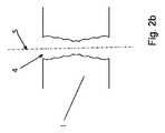
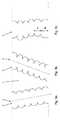
図1は、板状の加工物1に穴を配設する際の本方法の個々の工程から成る、レーザービームを照射した後、エッチングすることにより板状の加工物に穴を配設するための本方法の複数の工程のフロー図を図示している。そのために、図1aでは、加工物1の表面にレーザービーム2を向けている。この場合、加工物1の厚さdは3mmまでである。このレーザービーム2の作用時間は極めて短く選定されており、その結果、加工物1の改変だけがレーザービームのビーム軸線の周りに同心に生じる。そのために、加工物1が透過する波長でレーザーを動作させる。そのようにして改変された、欠損箇所3を有する領域が、図1bに複数の小胞の直線的な鎖列の形で図示されている。図1cに図示された本方法の次の工程では、図示されていないエッチング剤の作用のために、事前にレーザービーム2により改変を施された、加工物1の欠損箇所3により形成される領域に異方性の材料浸食を引き起こす。それにより、円筒形の作用ゾーンに沿った加工物1の穴として、窪み4が出現する。FIG. 1 is for arranging holes in a plate-shaped
この穴は、図2aと2b及び図3a〜3cの図面から分かる通り、外被面上において周囲を巡る多数の同心構造を有する。 As can be seen from the drawings of FIGS. 2a and 2b and 3a to 3c, this hole has a large number of concentric structures around the outer cover surface.
この場合、窪み4は、事前に生成した欠損箇所3をエッチング作用により加工物1内の中空空間にまで拡大して、エッチングプロセスにより徐々に繋げる形で、互いに連なる多数の欠損箇所3を徐々にエッチングすることによって形成される。それによって、エッチング液が一つの欠損箇所3から次の欠損箇所3に速く到達する。この場合、重力の影響は決定的ではないので、エッチング工程は、上方からでも下方からでも行なわれ、両方の外側から同時に開始される。外側領域におけるエッチング剤の比較的長い作用時間によって、図2bから分かる通り、欠損箇所3が外側表面の領域において円錐形に拡大している。 In this case, the
加工物1内の改変として生成された欠損箇所3によって、エッチングプロセスは、それらの欠損箇所3が配置された線5に追従する。この線5は、直線とするか、或いはエッチングプロセスが精確に守り得る殆ど任意の輪郭に従うことができる。そのため、殆ど任意の部分輪郭を生成することも初めて可能である。 Due to the
外側に有る欠損箇所3の領域において、加工物内の更に内側に有る欠損箇所3と比べて作用時間が、より長いことによって、より大きな拡大が生じるにも関わらず、全体として小さい円錐形の拡大部を観測することができる。 In the region of the
そのようにして形成された窪み4又は穴の輪郭は、エッチングプロセスの停止後において、一連の横断面拡大部及び狭窄部によって特徴付けられ、その形態は、ミミズを想起させ、これらの横断面拡大部及び狭窄部は、例えば、図2b及び3cから分かる通り、同じ横断面を有することもなく、図3cに図示されている通り、隣り合う横断面拡大部及び狭窄部との間隔a1,a2が同じであることもない。この場合、一つの横断面拡大部又は狭窄部は、主軸線に対する横断面内に、或いは図3aに図示されている通り、主軸線に対して傾斜した横断面内に配置することができる。 The contours of the
更に、隣り合う横断面拡大部又は狭窄部の中心点は、加工物1の表面に対して傾斜した共通の直線5上に有ることもでき、その結果、横断面拡大部又は狭窄部は、互いにずれて配置されるとともに、横断面拡大部又は狭窄部は、図3aに図示されている通り、外面に対して傾斜する方向又は図3bに図示されている通り、外面に対して平行な方向を向くことができる。 Further, the center points of the adjacent cross-sectional enlarged portions or constricted portions can be on a common straight line 5 inclined with respect to the surface of the
図3cから読み取ることができる通り、隣り合う横断面拡大部の面重心はそれぞれオフセットを有し、その結果、これらの横断面拡大部は、特に、共通の線上に配置されない。 As can be read from FIG. 3c, the surface centroids of the adjacent cross-sectional enlargement portions have offsets, and as a result, these cross-sectional enlargement portions are not particularly arranged on a common line.
Claims (11)
Translated fromJapaneseこの窪み(4)及び/又は穴が、互いに連なる多数の欠損箇所(3)にエッチングを徐々に進行させることによって形成されて、これらの欠損箇所(3)が、レーザービーム(2)との相互作用により生じることと、
一つのパルスの形のレーザービーム(2)の、ビーム軸線に沿った加工物の材料の厚さ全体に渡る空間的なビーム成形により材料内の複数箇所で集束されて形成される焦点が、加工物の材料と相互作用し、改変された材料領域の鎖列を一つのパルスで形成し、改変された材料領域の鎖列を形成するこの工程を、単一パルスを用いて行なうことによって、加工物(1)内の一鎖列の改変として、前記欠損箇所(3)を生成することと、
加工物(1)の主要な材料成分がガラスであることと、
を特徴とする方法。In a method of arranging at least one recess (4) and / or a hole in a plate-shaped workpiece (1) having a thickness of less than 3 mm.
The recesses (4) and / or holes are formed by gradually advancing etching to a large number of defective parts (3) connected to each other, and these defective parts (3) are mutually connected with the laser beam (2). What happens by the action and
The focal point of a single pulse-shaped laser beam (2), which is focused and formed at multiple points in the material by spatial beam shaping over the entire thickness of the material of the work piece along the beam axis, is processed. and materials interact with things, to form a chain sequence of the modified material region at one pulse, the step of forming a chain sequence of the modified material region, by a row ofUkoto using a single pulse As a modification of the single chain in the work piece (1), the defect portion (3) is generated.
The main material component of the processed product (1) is glass, and
A method characterized by.
Applications Claiming Priority (5)
| Application Number | Priority Date | Filing Date | Title |
|---|---|---|---|
| DE102014113339.0ADE102014113339A1 (en) | 2014-09-16 | 2014-09-16 | Method for producing recesses in a material |
| DE102014113339.0 | 2014-09-16 | ||
| DE102014116291.9 | 2014-11-07 | ||
| DE102014116291 | 2014-11-07 | ||
| PCT/DE2015/100333WO2016041544A1 (en) | 2014-09-16 | 2015-08-07 | Method for introducing at least one cutout or aperture into a sheetlike workpiece |
Related Child Applications (1)
| Application Number | Title | Priority Date | Filing Date |
|---|---|---|---|
| JP2020118488ADivisionJP7049404B2 (en) | 2014-09-16 | 2020-07-09 | A method of providing at least one removal part or hole in a plate-shaped work piece |
Publications (3)
| Publication Number | Publication Date |
|---|---|
| JP2017534458A JP2017534458A (en) | 2017-11-24 |
| JP2017534458A5 JP2017534458A5 (en) | 2019-11-28 |
| JP6782692B2true JP6782692B2 (en) | 2020-11-11 |
Family
ID=54072638
Family Applications (2)
| Application Number | Title | Priority Date | Filing Date |
|---|---|---|---|
| JP2017512917AActiveJP6782692B2 (en) | 2014-09-16 | 2015-08-07 | A method of arranging at least one depression or hole in a plate-shaped work piece |
| JP2020118488AActiveJP7049404B2 (en) | 2014-09-16 | 2020-07-09 | A method of providing at least one removal part or hole in a plate-shaped work piece |
Family Applications After (1)
| Application Number | Title | Priority Date | Filing Date |
|---|---|---|---|
| JP2020118488AActiveJP7049404B2 (en) | 2014-09-16 | 2020-07-09 | A method of providing at least one removal part or hole in a plate-shaped work piece |
Country Status (11)
| Country | Link |
|---|---|
| US (2) | US11610784B2 (en) |
| EP (2) | EP4061101A1 (en) |
| JP (2) | JP6782692B2 (en) |
| KR (6) | KR20170044143A (en) |
| CN (1) | CN107006128B (en) |
| ES (1) | ES2923764T3 (en) |
| LT (1) | LT3195706T (en) |
| MY (1) | MY196621A (en) |
| SG (2) | SG11201702091WA (en) |
| TW (1) | TWI616939B (en) |
| WO (1) | WO2016041544A1 (en) |
Families Citing this family (21)
| Publication number | Priority date | Publication date | Assignee | Title |
|---|---|---|---|---|
| DE102018100299A1 (en)* | 2017-01-27 | 2018-08-02 | Schott Ag | Structured plate-shaped glass element and method for its production |
| EP3592501B1 (en) | 2017-03-06 | 2021-10-06 | LPKF Laser & Electronics AG | Method for producing a technical mask |
| WO2018162385A1 (en) | 2017-03-06 | 2018-09-13 | Lpkf Laser & Electronics Ag | Method for producing at least one recess in a material by means of electromagnetic radiation and subsequent etching process |
| DE102018110211A1 (en)* | 2018-04-27 | 2019-10-31 | Schott Ag | Method for producing fine structures in the volume of a substrate made of brittle-hard material |
| TWI678342B (en) | 2018-11-09 | 2019-12-01 | 財團法人工業技術研究院 | Cutting method for forming chamfered corners |
| DE102020100848B4 (en) | 2019-01-29 | 2023-07-27 | Lpkf Laser & Electronics Aktiengesellschaft | Process for microstructuring a glass substrate using laser radiation |
| DE102019201347B3 (en)* | 2019-02-01 | 2020-06-18 | Lpkf Laser & Electronics Ag | Manufacture of metallic conductor tracks on glass |
| KR20210124384A (en)* | 2019-02-08 | 2021-10-14 | 코닝 인코포레이티드 | How to Laser Machining Transparent Workpieces Using Pulsed Laser Beam Focus Lines and Vapor Etching |
| DE102019121827A1 (en)* | 2019-08-13 | 2021-02-18 | Trumpf Laser- Und Systemtechnik Gmbh | Laser etching with varying etching selectivity |
| CN113594014B (en)* | 2020-04-30 | 2024-04-12 | 中微半导体设备(上海)股份有限公司 | Component, plasma reaction device, and component processing method |
| DE102020114195A1 (en) | 2020-05-27 | 2021-12-02 | Lpkf Laser & Electronics Aktiengesellschaft | Method for making a recess in a substrate |
| CN111799169B (en)* | 2020-07-17 | 2024-05-28 | 绍兴同芯成集成电路有限公司 | Process for processing TGV by combining femtosecond laser with HF wet etching |
| DE102020120370B3 (en) | 2020-08-03 | 2022-02-03 | Infineon Technologies Ag | MEMS SENSOR WITH PARTICULATE FILTER AND METHOD FOR ITS MANUFACTURE |
| KR20220019158A (en) | 2020-08-06 | 2022-02-16 | 삼성디스플레이 주식회사 | Window and display device comprising theferof |
| EP4011846A1 (en) | 2020-12-09 | 2022-06-15 | Schott Ag | Method of structuring a glass element and structured glass element produced thereby |
| DE102021204675B4 (en) | 2021-05-07 | 2023-05-17 | Lpkf Laser & Electronics Se | Device and method for cell cultivation |
| CN113510364B (en)* | 2021-07-28 | 2022-11-25 | 广东工业大学 | A three-dimensional cavity structure forming method based on laser-assisted dissolution |
| EP4296244A1 (en) | 2022-06-21 | 2023-12-27 | LPKF Laser & Electronics SE | Substrate carrier made of glass for processing a substrate and a method for producing the same |
| DE102022127259A1 (en) | 2022-10-18 | 2024-04-18 | Lpkf Laser & Electronics Aktiengesellschaft | Method and device for imaging a beam onto an object and method for making an opening in a workpiece by means of this method |
| DE102023125725A1 (en)* | 2023-09-22 | 2025-03-27 | Schott Ag | Laser-structured optical element |
| DE102024105120A1 (en) | 2024-02-23 | 2025-08-28 | Lpkf Laser & Electronics Se | Method for integrating and/or processing at least one substrate and substrate stack |
Family Cites Families (20)
| Publication number | Priority date | Publication date | Assignee | Title |
|---|---|---|---|---|
| WO2001015819A1 (en)* | 1999-08-30 | 2001-03-08 | Board Of Regents University Of Nebraska-Lincoln | Three-dimensional electrical interconnects |
| JP4880820B2 (en) | 2001-01-19 | 2012-02-22 | 株式会社レーザーシステム | Laser assisted machining method |
| JP4418282B2 (en) | 2004-03-31 | 2010-02-17 | 株式会社レーザーシステム | Laser processing method |
| JP4222296B2 (en) | 2004-11-22 | 2009-02-12 | 住友電気工業株式会社 | Laser processing method and laser processing apparatus |
| US9138913B2 (en) | 2005-09-08 | 2015-09-22 | Imra America, Inc. | Transparent material processing with an ultrashort pulse laser |
| JP2011218398A (en)* | 2010-04-08 | 2011-11-04 | Fujikura Ltd | Method for forming microstructure, laser irradiation device, and substrate |
| DE102010025966B4 (en) | 2010-07-02 | 2012-03-08 | Schott Ag | Interposer and method for making holes in an interposer |
| JP6121901B2 (en)* | 2010-07-12 | 2017-04-26 | ロフィン−シナー テクノロジーズ インコーポレーテッド | Material processing by laser filament formation |
| WO2012014723A1 (en)* | 2010-07-26 | 2012-02-02 | 浜松ホトニクス株式会社 | Method for manufacturing light-absorbing substrate and method for manufacturing die for manufacturing light-absorbing substrate |
| WO2012014720A1 (en) | 2010-07-26 | 2012-02-02 | 浜松ホトニクス株式会社 | Laser processing method |
| WO2012014710A1 (en)* | 2010-07-26 | 2012-02-02 | 浜松ホトニクス株式会社 | Laser processing method |
| EP2600397B1 (en) | 2010-07-26 | 2019-08-21 | Hamamatsu Photonics K.K. | Method for manufacturing interposer |
| US8933367B2 (en) | 2011-02-09 | 2015-01-13 | Sumitomo Electric Industries, Ltd. | Laser processing method |
| CN105246850B (en) | 2012-11-29 | 2018-01-30 | 康宁股份有限公司 | Pass through the method for laser damage and etching manufacture glassware |
| EP2754524B1 (en) | 2013-01-15 | 2015-11-25 | Corning Laser Technologies GmbH | Method of and apparatus for laser based processing of flat substrates being wafer or glass element using a laser beam line |
| JP6113529B2 (en)* | 2013-03-05 | 2017-04-12 | 株式会社ディスコ | Wafer processing method |
| DE102013223637B4 (en)† | 2013-11-20 | 2018-02-01 | Trumpf Laser- Und Systemtechnik Gmbh | A method of treating a laser transparent substrate for subsequently separating the substrate |
| US10293436B2 (en)* | 2013-12-17 | 2019-05-21 | Corning Incorporated | Method for rapid laser drilling of holes in glass and products made therefrom |
| KR20190078595A (en)* | 2016-11-04 | 2019-07-04 | 코닝 인코포레이티드 | A micro-perforated panel system, an application, and a method of manufacturing a micro-perforated panel system |
| US11344973B2 (en)* | 2018-04-19 | 2022-05-31 | Corning Incorporated | Methods for forming holes in substrates |
- 2015
- 2015-08-07JPJP2017512917Apatent/JP6782692B2/enactiveActive
- 2015-08-07SGSG11201702091WApatent/SG11201702091WA/enunknown
- 2015-08-07EPEP22167179.5Apatent/EP4061101A1/enactivePending
- 2015-08-07KRKR1020177007041Apatent/KR20170044143A/ennot_activeCeased
- 2015-08-07EPEP15762474.3Apatent/EP3195706B2/enactiveActive
- 2015-08-07SGSG10201902331XApatent/SG10201902331XA/enunknown
- 2015-08-07USUS15/511,272patent/US11610784B2/enactiveActive
- 2015-08-07MYMYPI2017700845Apatent/MY196621A/enunknown
- 2015-08-07KRKR1020197015976Apatent/KR20190065480A/ennot_activeCeased
- 2015-08-07KRKR1020217005121Apatent/KR20210022773A/ennot_activeCeased
- 2015-08-07LTLTEPPCT/DE2015/100333Tpatent/LT3195706T/enunknown
- 2015-08-07CNCN201580049903.1Apatent/CN107006128B/enactiveActive
- 2015-08-07ESES15762474Tpatent/ES2923764T3/enactiveActive
- 2015-08-07KRKR1020237018486Apatent/KR102813417B1/enactiveActive
- 2015-08-07KRKR1020257028228Apatent/KR20250133802A/enactivePending
- 2015-08-07WOPCT/DE2015/100333patent/WO2016041544A1/enactiveApplication Filing
- 2015-08-07KRKR1020257016919Apatent/KR102851778B1/enactiveActive
- 2015-09-09TWTW104129751Apatent/TWI616939B/enactive
- 2020
- 2020-07-09JPJP2020118488Apatent/JP7049404B2/enactiveActive
- 2022
- 2022-04-01USUS17/711,136patent/US20220223434A1/enactivePending
Also Published As
| Publication number | Publication date |
|---|---|
| US20170256422A1 (en) | 2017-09-07 |
| KR20170044143A (en) | 2017-04-24 |
| SG11201702091WA (en) | 2017-04-27 |
| KR20250133802A (en) | 2025-09-08 |
| LT3195706T (en) | 2022-08-10 |
| MY196621A (en) | 2023-04-23 |
| CN107006128B (en) | 2020-05-19 |
| WO2016041544A1 (en) | 2016-03-24 |
| KR102813417B1 (en) | 2025-05-29 |
| JP2017534458A (en) | 2017-11-24 |
| EP3195706B2 (en) | 2025-05-14 |
| TW201621986A (en) | 2016-06-16 |
| KR20250079054A (en) | 2025-06-04 |
| JP2020185613A (en) | 2020-11-19 |
| SG10201902331XA (en) | 2019-04-29 |
| TWI616939B (en) | 2018-03-01 |
| US20220223434A1 (en) | 2022-07-14 |
| US11610784B2 (en) | 2023-03-21 |
| ES2923764T3 (en) | 2022-09-30 |
| EP3195706A1 (en) | 2017-07-26 |
| EP4061101A1 (en) | 2022-09-21 |
| JP7049404B2 (en) | 2022-04-06 |
| KR20190065480A (en) | 2019-06-11 |
| KR102851778B1 (en) | 2025-09-01 |
| KR20230084606A (en) | 2023-06-13 |
| CN107006128A (en) | 2017-08-01 |
| KR20210022773A (en) | 2021-03-03 |
| EP3195706B1 (en) | 2022-06-01 |
Similar Documents
| Publication | Publication Date | Title |
|---|---|---|
| JP6782692B2 (en) | A method of arranging at least one depression or hole in a plate-shaped work piece | |
| JP6162827B2 (en) | Method and apparatus for separating substrates | |
| JP6186016B2 (en) | Method and apparatus for drilling through holes in a substrate | |
| JP6898998B2 (en) | A method for creating at least one void in a material by electromagnetic radiation and subsequent etching processes. | |
| JP6381753B2 (en) | Method and apparatus for non-ablation photoacoustic compression processing of transparent materials using filamentation by bursts of ultrafast laser pulses | |
| CN104768698B (en) | Method for producing aligned linear breaking points by ultra-short focussed, pulsed laser radiation | |
| CN106029286B (en) | Method for rapid laser drilling in glass and products made therefrom | |
| CN105392593B (en) | Apparatus and method for cutting contours from flat substrates by means of laser | |
| JP2017501884A (en) | Method of laser cutting a sapphire substrate with a laser, and an article comprising sapphire having an edge with a series of defects | |
| KR20190025721A (en) | Laser processing apparatus and method for laser processing a workpiece |
Legal Events
| Date | Code | Title | Description |
|---|---|---|---|
| A621 | Written request for application examination | Free format text:JAPANESE INTERMEDIATE CODE: A621 Effective date:20170306 | |
| A131 | Notification of reasons for refusal | Free format text:JAPANESE INTERMEDIATE CODE: A131 Effective date:20171206 | |
| A521 | Request for written amendment filed | Free format text:JAPANESE INTERMEDIATE CODE: A523 Effective date:20180220 | |
| A131 | Notification of reasons for refusal | Free format text:JAPANESE INTERMEDIATE CODE: A131 Effective date:20180801 | |
| A601 | Written request for extension of time | Free format text:JAPANESE INTERMEDIATE CODE: A601 Effective date:20181025 | |
| A524 | Written submission of copy of amendment under article 19 pct | Free format text:JAPANESE INTERMEDIATE CODE: A524 Effective date:20181226 | |
| A521 | Request for written amendment filed | Free format text:JAPANESE INTERMEDIATE CODE: A523 Effective date:20181227 | |
| A02 | Decision of refusal | Free format text:JAPANESE INTERMEDIATE CODE: A02 Effective date:20190605 | |
| A521 | Request for written amendment filed | Free format text:JAPANESE INTERMEDIATE CODE: A523 Effective date:20191002 | |
| A524 | Written submission of copy of amendment under article 19 pct | Free format text:JAPANESE INTERMEDIATE CODE: A524 Effective date:20191002 | |
| A521 | Request for written amendment filed | Free format text:JAPANESE INTERMEDIATE CODE: A821 Effective date:20191002 | |
| A911 | Transfer to examiner for re-examination before appeal (zenchi) | Free format text:JAPANESE INTERMEDIATE CODE: A911 Effective date:20191023 | |
| A912 | Re-examination (zenchi) completed and case transferred to appeal board | Free format text:JAPANESE INTERMEDIATE CODE: A912 Effective date:20191206 | |
| A601 | Written request for extension of time | Free format text:JAPANESE INTERMEDIATE CODE: A601 Effective date:20200701 | |
| RD04 | Notification of resignation of power of attorney | Free format text:JAPANESE INTERMEDIATE CODE: A7424 Effective date:20200703 | |
| A521 | Request for written amendment filed | Free format text:JAPANESE INTERMEDIATE CODE: A523 Effective date:20200709 | |
| A61 | First payment of annual fees (during grant procedure) | Free format text:JAPANESE INTERMEDIATE CODE: A61 Effective date:20201020 | |
| R150 | Certificate of patent or registration of utility model | Ref document number:6782692 Country of ref document:JP Free format text:JAPANESE INTERMEDIATE CODE: R150 | |
| R250 | Receipt of annual fees | Free format text:JAPANESE INTERMEDIATE CODE: R250 | |
| R250 | Receipt of annual fees | Free format text:JAPANESE INTERMEDIATE CODE: R250 |