JP6778872B2 - Driving support device and driving support method - Google Patents
Driving support device and driving support methodDownload PDFInfo
- Publication number
- JP6778872B2 JP6778872B2JP2016127972AJP2016127972AJP6778872B2JP 6778872 B2JP6778872 B2JP 6778872B2JP 2016127972 AJP2016127972 AJP 2016127972AJP 2016127972 AJP2016127972 AJP 2016127972AJP 6778872 B2JP6778872 B2JP 6778872B2
- Authority
- JP
- Japan
- Prior art keywords
- driver
- vehicle
- driving
- detection unit
- support device
- Prior art date
- Legal status (The legal status is an assumption and is not a legal conclusion. Google has not performed a legal analysis and makes no representation as to the accuracy of the status listed.)
- Active
Links
Images


Classifications
- B—PERFORMING OPERATIONS; TRANSPORTING
- B60—VEHICLES IN GENERAL
- B60K—ARRANGEMENT OR MOUNTING OF PROPULSION UNITS OR OF TRANSMISSIONS IN VEHICLES; ARRANGEMENT OR MOUNTING OF PLURAL DIVERSE PRIME-MOVERS IN VEHICLES; AUXILIARY DRIVES FOR VEHICLES; INSTRUMENTATION OR DASHBOARDS FOR VEHICLES; ARRANGEMENTS IN CONNECTION WITH COOLING, AIR INTAKE, GAS EXHAUST OR FUEL SUPPLY OF PROPULSION UNITS IN VEHICLES
- B60K28/00—Safety devices for propulsion-unit control, specially adapted for, or arranged in, vehicles, e.g. preventing fuel supply or ignition in the event of potentially dangerous conditions
- B60K28/02—Safety devices for propulsion-unit control, specially adapted for, or arranged in, vehicles, e.g. preventing fuel supply or ignition in the event of potentially dangerous conditions responsive to conditions relating to the driver
- B60K28/06—Safety devices for propulsion-unit control, specially adapted for, or arranged in, vehicles, e.g. preventing fuel supply or ignition in the event of potentially dangerous conditions responsive to conditions relating to the driver responsive to incapacity of driver
- B—PERFORMING OPERATIONS; TRANSPORTING
- B60—VEHICLES IN GENERAL
- B60K—ARRANGEMENT OR MOUNTING OF PROPULSION UNITS OR OF TRANSMISSIONS IN VEHICLES; ARRANGEMENT OR MOUNTING OF PLURAL DIVERSE PRIME-MOVERS IN VEHICLES; AUXILIARY DRIVES FOR VEHICLES; INSTRUMENTATION OR DASHBOARDS FOR VEHICLES; ARRANGEMENTS IN CONNECTION WITH COOLING, AIR INTAKE, GAS EXHAUST OR FUEL SUPPLY OF PROPULSION UNITS IN VEHICLES
- B60K35/00—Instruments specially adapted for vehicles; Arrangement of instruments in or on vehicles
- B60K35/20—Output arrangements, i.e. from vehicle to user, associated with vehicle functions or specially adapted therefor
- B60K35/28—Output arrangements, i.e. from vehicle to user, associated with vehicle functions or specially adapted therefor characterised by the type of the output information, e.g. video entertainment or vehicle dynamics information; characterised by the purpose of the output information, e.g. for attracting the attention of the driver
- B—PERFORMING OPERATIONS; TRANSPORTING
- B60—VEHICLES IN GENERAL
- B60K—ARRANGEMENT OR MOUNTING OF PROPULSION UNITS OR OF TRANSMISSIONS IN VEHICLES; ARRANGEMENT OR MOUNTING OF PLURAL DIVERSE PRIME-MOVERS IN VEHICLES; AUXILIARY DRIVES FOR VEHICLES; INSTRUMENTATION OR DASHBOARDS FOR VEHICLES; ARRANGEMENTS IN CONNECTION WITH COOLING, AIR INTAKE, GAS EXHAUST OR FUEL SUPPLY OF PROPULSION UNITS IN VEHICLES
- B60K35/00—Instruments specially adapted for vehicles; Arrangement of instruments in or on vehicles
- B60K35/20—Output arrangements, i.e. from vehicle to user, associated with vehicle functions or specially adapted therefor
- B60K35/29—Instruments characterised by the way in which information is handled, e.g. showing information on plural displays or prioritising information according to driving conditions
- B—PERFORMING OPERATIONS; TRANSPORTING
- B60—VEHICLES IN GENERAL
- B60K—ARRANGEMENT OR MOUNTING OF PROPULSION UNITS OR OF TRANSMISSIONS IN VEHICLES; ARRANGEMENT OR MOUNTING OF PLURAL DIVERSE PRIME-MOVERS IN VEHICLES; AUXILIARY DRIVES FOR VEHICLES; INSTRUMENTATION OR DASHBOARDS FOR VEHICLES; ARRANGEMENTS IN CONNECTION WITH COOLING, AIR INTAKE, GAS EXHAUST OR FUEL SUPPLY OF PROPULSION UNITS IN VEHICLES
- B60K35/00—Instruments specially adapted for vehicles; Arrangement of instruments in or on vehicles
- B60K35/80—Arrangements for controlling instruments
- B—PERFORMING OPERATIONS; TRANSPORTING
- B60—VEHICLES IN GENERAL
- B60W—CONJOINT CONTROL OF VEHICLE SUB-UNITS OF DIFFERENT TYPE OR DIFFERENT FUNCTION; CONTROL SYSTEMS SPECIALLY ADAPTED FOR HYBRID VEHICLES; ROAD VEHICLE DRIVE CONTROL SYSTEMS FOR PURPOSES NOT RELATED TO THE CONTROL OF A PARTICULAR SUB-UNIT
- B60W30/00—Purposes of road vehicle drive control systems not related to the control of a particular sub-unit, e.g. of systems using conjoint control of vehicle sub-units
- B60W30/18—Propelling the vehicle
- B60W30/182—Selecting between different operative modes, e.g. comfort and performance modes
- B—PERFORMING OPERATIONS; TRANSPORTING
- B60—VEHICLES IN GENERAL
- B60W—CONJOINT CONTROL OF VEHICLE SUB-UNITS OF DIFFERENT TYPE OR DIFFERENT FUNCTION; CONTROL SYSTEMS SPECIALLY ADAPTED FOR HYBRID VEHICLES; ROAD VEHICLE DRIVE CONTROL SYSTEMS FOR PURPOSES NOT RELATED TO THE CONTROL OF A PARTICULAR SUB-UNIT
- B60W40/00—Estimation or calculation of non-directly measurable driving parameters for road vehicle drive control systems not related to the control of a particular sub unit, e.g. by using mathematical models
- B60W40/02—Estimation or calculation of non-directly measurable driving parameters for road vehicle drive control systems not related to the control of a particular sub unit, e.g. by using mathematical models related to ambient conditions
- B60W40/06—Road conditions
- B—PERFORMING OPERATIONS; TRANSPORTING
- B60—VEHICLES IN GENERAL
- B60W—CONJOINT CONTROL OF VEHICLE SUB-UNITS OF DIFFERENT TYPE OR DIFFERENT FUNCTION; CONTROL SYSTEMS SPECIALLY ADAPTED FOR HYBRID VEHICLES; ROAD VEHICLE DRIVE CONTROL SYSTEMS FOR PURPOSES NOT RELATED TO THE CONTROL OF A PARTICULAR SUB-UNIT
- B60W40/00—Estimation or calculation of non-directly measurable driving parameters for road vehicle drive control systems not related to the control of a particular sub unit, e.g. by using mathematical models
- B60W40/08—Estimation or calculation of non-directly measurable driving parameters for road vehicle drive control systems not related to the control of a particular sub unit, e.g. by using mathematical models related to drivers or passengers
- B60W40/09—Driving style or behaviour
- B—PERFORMING OPERATIONS; TRANSPORTING
- B60—VEHICLES IN GENERAL
- B60W—CONJOINT CONTROL OF VEHICLE SUB-UNITS OF DIFFERENT TYPE OR DIFFERENT FUNCTION; CONTROL SYSTEMS SPECIALLY ADAPTED FOR HYBRID VEHICLES; ROAD VEHICLE DRIVE CONTROL SYSTEMS FOR PURPOSES NOT RELATED TO THE CONTROL OF A PARTICULAR SUB-UNIT
- B60W50/00—Details of control systems for road vehicle drive control not related to the control of a particular sub-unit, e.g. process diagnostic or vehicle driver interfaces
- B60W50/08—Interaction between the driver and the control system
- B60W50/082—Selecting or switching between different modes of propelling
- B—PERFORMING OPERATIONS; TRANSPORTING
- B60—VEHICLES IN GENERAL
- B60W—CONJOINT CONTROL OF VEHICLE SUB-UNITS OF DIFFERENT TYPE OR DIFFERENT FUNCTION; CONTROL SYSTEMS SPECIALLY ADAPTED FOR HYBRID VEHICLES; ROAD VEHICLE DRIVE CONTROL SYSTEMS FOR PURPOSES NOT RELATED TO THE CONTROL OF A PARTICULAR SUB-UNIT
- B60W50/00—Details of control systems for road vehicle drive control not related to the control of a particular sub-unit, e.g. process diagnostic or vehicle driver interfaces
- B60W50/08—Interaction between the driver and the control system
- B60W50/14—Means for informing the driver, warning the driver or prompting a driver intervention
- B—PERFORMING OPERATIONS; TRANSPORTING
- B60—VEHICLES IN GENERAL
- B60W—CONJOINT CONTROL OF VEHICLE SUB-UNITS OF DIFFERENT TYPE OR DIFFERENT FUNCTION; CONTROL SYSTEMS SPECIALLY ADAPTED FOR HYBRID VEHICLES; ROAD VEHICLE DRIVE CONTROL SYSTEMS FOR PURPOSES NOT RELATED TO THE CONTROL OF A PARTICULAR SUB-UNIT
- B60W60/00—Drive control systems specially adapted for autonomous road vehicles
- B60W60/005—Handover processes
- B60W60/0053—Handover processes from vehicle to occupant
- B—PERFORMING OPERATIONS; TRANSPORTING
- B60—VEHICLES IN GENERAL
- B60W—CONJOINT CONTROL OF VEHICLE SUB-UNITS OF DIFFERENT TYPE OR DIFFERENT FUNCTION; CONTROL SYSTEMS SPECIALLY ADAPTED FOR HYBRID VEHICLES; ROAD VEHICLE DRIVE CONTROL SYSTEMS FOR PURPOSES NOT RELATED TO THE CONTROL OF A PARTICULAR SUB-UNIT
- B60W60/00—Drive control systems specially adapted for autonomous road vehicles
- B60W60/005—Handover processes
- B60W60/0057—Estimation of the time available or required for the handover
- B—PERFORMING OPERATIONS; TRANSPORTING
- B60—VEHICLES IN GENERAL
- B60W—CONJOINT CONTROL OF VEHICLE SUB-UNITS OF DIFFERENT TYPE OR DIFFERENT FUNCTION; CONTROL SYSTEMS SPECIALLY ADAPTED FOR HYBRID VEHICLES; ROAD VEHICLE DRIVE CONTROL SYSTEMS FOR PURPOSES NOT RELATED TO THE CONTROL OF A PARTICULAR SUB-UNIT
- B60W60/00—Drive control systems specially adapted for autonomous road vehicles
- B60W60/005—Handover processes
- B60W60/0059—Estimation of the risk associated with autonomous or manual driving, e.g. situation too complex, sensor failure or driver incapacity
- B—PERFORMING OPERATIONS; TRANSPORTING
- B60—VEHICLES IN GENERAL
- B60W—CONJOINT CONTROL OF VEHICLE SUB-UNITS OF DIFFERENT TYPE OR DIFFERENT FUNCTION; CONTROL SYSTEMS SPECIALLY ADAPTED FOR HYBRID VEHICLES; ROAD VEHICLE DRIVE CONTROL SYSTEMS FOR PURPOSES NOT RELATED TO THE CONTROL OF A PARTICULAR SUB-UNIT
- B60W60/00—Drive control systems specially adapted for autonomous road vehicles
- B60W60/005—Handover processes
- B60W60/0061—Aborting handover process
- G—PHYSICS
- G05—CONTROLLING; REGULATING
- G05D—SYSTEMS FOR CONTROLLING OR REGULATING NON-ELECTRIC VARIABLES
- G05D1/00—Control of position, course, altitude or attitude of land, water, air or space vehicles, e.g. using automatic pilots
- G05D1/0055—Control of position, course, altitude or attitude of land, water, air or space vehicles, e.g. using automatic pilots with safety arrangements
- G05D1/0061—Control of position, course, altitude or attitude of land, water, air or space vehicles, e.g. using automatic pilots with safety arrangements for transition from automatic pilot to manual pilot and vice versa
- B—PERFORMING OPERATIONS; TRANSPORTING
- B60—VEHICLES IN GENERAL
- B60K—ARRANGEMENT OR MOUNTING OF PROPULSION UNITS OR OF TRANSMISSIONS IN VEHICLES; ARRANGEMENT OR MOUNTING OF PLURAL DIVERSE PRIME-MOVERS IN VEHICLES; AUXILIARY DRIVES FOR VEHICLES; INSTRUMENTATION OR DASHBOARDS FOR VEHICLES; ARRANGEMENTS IN CONNECTION WITH COOLING, AIR INTAKE, GAS EXHAUST OR FUEL SUPPLY OF PROPULSION UNITS IN VEHICLES
- B60K2360/00—Indexing scheme associated with groups B60K35/00 or B60K37/00 relating to details of instruments or dashboards
- B60K2360/16—Type of output information
- B60K2360/175—Autonomous driving
- B—PERFORMING OPERATIONS; TRANSPORTING
- B60—VEHICLES IN GENERAL
- B60K—ARRANGEMENT OR MOUNTING OF PROPULSION UNITS OR OF TRANSMISSIONS IN VEHICLES; ARRANGEMENT OR MOUNTING OF PLURAL DIVERSE PRIME-MOVERS IN VEHICLES; AUXILIARY DRIVES FOR VEHICLES; INSTRUMENTATION OR DASHBOARDS FOR VEHICLES; ARRANGEMENTS IN CONNECTION WITH COOLING, AIR INTAKE, GAS EXHAUST OR FUEL SUPPLY OF PROPULSION UNITS IN VEHICLES
- B60K2360/00—Indexing scheme associated with groups B60K35/00 or B60K37/00 relating to details of instruments or dashboards
- B60K2360/18—Information management
- B60K2360/186—Displaying information according to relevancy
- B60K2360/1868—Displaying information according to relevancy according to driving situations
- B—PERFORMING OPERATIONS; TRANSPORTING
- B60—VEHICLES IN GENERAL
- B60K—ARRANGEMENT OR MOUNTING OF PROPULSION UNITS OR OF TRANSMISSIONS IN VEHICLES; ARRANGEMENT OR MOUNTING OF PLURAL DIVERSE PRIME-MOVERS IN VEHICLES; AUXILIARY DRIVES FOR VEHICLES; INSTRUMENTATION OR DASHBOARDS FOR VEHICLES; ARRANGEMENTS IN CONNECTION WITH COOLING, AIR INTAKE, GAS EXHAUST OR FUEL SUPPLY OF PROPULSION UNITS IN VEHICLES
- B60K2360/00—Indexing scheme associated with groups B60K35/00 or B60K37/00 relating to details of instruments or dashboards
- B60K2360/55—Remote control arrangements
- B60K2360/56—Remote control arrangements using mobile devices
- B60K2360/566—Mobile devices displaying vehicle information
- B—PERFORMING OPERATIONS; TRANSPORTING
- B60—VEHICLES IN GENERAL
- B60W—CONJOINT CONTROL OF VEHICLE SUB-UNITS OF DIFFERENT TYPE OR DIFFERENT FUNCTION; CONTROL SYSTEMS SPECIALLY ADAPTED FOR HYBRID VEHICLES; ROAD VEHICLE DRIVE CONTROL SYSTEMS FOR PURPOSES NOT RELATED TO THE CONTROL OF A PARTICULAR SUB-UNIT
- B60W40/00—Estimation or calculation of non-directly measurable driving parameters for road vehicle drive control systems not related to the control of a particular sub unit, e.g. by using mathematical models
- B60W40/08—Estimation or calculation of non-directly measurable driving parameters for road vehicle drive control systems not related to the control of a particular sub unit, e.g. by using mathematical models related to drivers or passengers
- B60W2040/0818—Inactivity or incapacity of driver
- B60W2040/0827—Inactivity or incapacity of driver due to sleepiness
- B—PERFORMING OPERATIONS; TRANSPORTING
- B60—VEHICLES IN GENERAL
- B60W—CONJOINT CONTROL OF VEHICLE SUB-UNITS OF DIFFERENT TYPE OR DIFFERENT FUNCTION; CONTROL SYSTEMS SPECIALLY ADAPTED FOR HYBRID VEHICLES; ROAD VEHICLE DRIVE CONTROL SYSTEMS FOR PURPOSES NOT RELATED TO THE CONTROL OF A PARTICULAR SUB-UNIT
- B60W40/00—Estimation or calculation of non-directly measurable driving parameters for road vehicle drive control systems not related to the control of a particular sub unit, e.g. by using mathematical models
- B60W40/08—Estimation or calculation of non-directly measurable driving parameters for road vehicle drive control systems not related to the control of a particular sub unit, e.g. by using mathematical models related to drivers or passengers
- B60W2040/0872—Driver physiology
- B—PERFORMING OPERATIONS; TRANSPORTING
- B60—VEHICLES IN GENERAL
- B60W—CONJOINT CONTROL OF VEHICLE SUB-UNITS OF DIFFERENT TYPE OR DIFFERENT FUNCTION; CONTROL SYSTEMS SPECIALLY ADAPTED FOR HYBRID VEHICLES; ROAD VEHICLE DRIVE CONTROL SYSTEMS FOR PURPOSES NOT RELATED TO THE CONTROL OF A PARTICULAR SUB-UNIT
- B60W50/00—Details of control systems for road vehicle drive control not related to the control of a particular sub-unit, e.g. process diagnostic or vehicle driver interfaces
- B60W2050/0062—Adapting control system settings
- B60W2050/007—Switching between manual and automatic parameter input, and vice versa
- B60W2050/0072—Controller asks driver to take over
- B—PERFORMING OPERATIONS; TRANSPORTING
- B60—VEHICLES IN GENERAL
- B60W—CONJOINT CONTROL OF VEHICLE SUB-UNITS OF DIFFERENT TYPE OR DIFFERENT FUNCTION; CONTROL SYSTEMS SPECIALLY ADAPTED FOR HYBRID VEHICLES; ROAD VEHICLE DRIVE CONTROL SYSTEMS FOR PURPOSES NOT RELATED TO THE CONTROL OF A PARTICULAR SUB-UNIT
- B60W50/00—Details of control systems for road vehicle drive control not related to the control of a particular sub-unit, e.g. process diagnostic or vehicle driver interfaces
- B60W50/08—Interaction between the driver and the control system
- B60W50/14—Means for informing the driver, warning the driver or prompting a driver intervention
- B60W2050/146—Display means
- B—PERFORMING OPERATIONS; TRANSPORTING
- B60—VEHICLES IN GENERAL
- B60W—CONJOINT CONTROL OF VEHICLE SUB-UNITS OF DIFFERENT TYPE OR DIFFERENT FUNCTION; CONTROL SYSTEMS SPECIALLY ADAPTED FOR HYBRID VEHICLES; ROAD VEHICLE DRIVE CONTROL SYSTEMS FOR PURPOSES NOT RELATED TO THE CONTROL OF A PARTICULAR SUB-UNIT
- B60W2420/00—Indexing codes relating to the type of sensors based on the principle of their operation
- B60W2420/40—Photo, light or radio wave sensitive means, e.g. infrared sensors
- B60W2420/403—Image sensing, e.g. optical camera
- B—PERFORMING OPERATIONS; TRANSPORTING
- B60—VEHICLES IN GENERAL
- B60W—CONJOINT CONTROL OF VEHICLE SUB-UNITS OF DIFFERENT TYPE OR DIFFERENT FUNCTION; CONTROL SYSTEMS SPECIALLY ADAPTED FOR HYBRID VEHICLES; ROAD VEHICLE DRIVE CONTROL SYSTEMS FOR PURPOSES NOT RELATED TO THE CONTROL OF A PARTICULAR SUB-UNIT
- B60W2420/00—Indexing codes relating to the type of sensors based on the principle of their operation
- B60W2420/54—Audio sensitive means, e.g. ultrasound
- B—PERFORMING OPERATIONS; TRANSPORTING
- B60—VEHICLES IN GENERAL
- B60W—CONJOINT CONTROL OF VEHICLE SUB-UNITS OF DIFFERENT TYPE OR DIFFERENT FUNCTION; CONTROL SYSTEMS SPECIALLY ADAPTED FOR HYBRID VEHICLES; ROAD VEHICLE DRIVE CONTROL SYSTEMS FOR PURPOSES NOT RELATED TO THE CONTROL OF A PARTICULAR SUB-UNIT
- B60W2520/00—Input parameters relating to overall vehicle dynamics
- B60W2520/10—Longitudinal speed
- B—PERFORMING OPERATIONS; TRANSPORTING
- B60—VEHICLES IN GENERAL
- B60W—CONJOINT CONTROL OF VEHICLE SUB-UNITS OF DIFFERENT TYPE OR DIFFERENT FUNCTION; CONTROL SYSTEMS SPECIALLY ADAPTED FOR HYBRID VEHICLES; ROAD VEHICLE DRIVE CONTROL SYSTEMS FOR PURPOSES NOT RELATED TO THE CONTROL OF A PARTICULAR SUB-UNIT
- B60W2540/00—Input parameters relating to occupants
- B60W2540/21—Voice
- B—PERFORMING OPERATIONS; TRANSPORTING
- B60—VEHICLES IN GENERAL
- B60W—CONJOINT CONTROL OF VEHICLE SUB-UNITS OF DIFFERENT TYPE OR DIFFERENT FUNCTION; CONTROL SYSTEMS SPECIALLY ADAPTED FOR HYBRID VEHICLES; ROAD VEHICLE DRIVE CONTROL SYSTEMS FOR PURPOSES NOT RELATED TO THE CONTROL OF A PARTICULAR SUB-UNIT
- B60W2540/00—Input parameters relating to occupants
- B60W2540/22—Psychological state; Stress level or workload
- B—PERFORMING OPERATIONS; TRANSPORTING
- B60—VEHICLES IN GENERAL
- B60W—CONJOINT CONTROL OF VEHICLE SUB-UNITS OF DIFFERENT TYPE OR DIFFERENT FUNCTION; CONTROL SYSTEMS SPECIALLY ADAPTED FOR HYBRID VEHICLES; ROAD VEHICLE DRIVE CONTROL SYSTEMS FOR PURPOSES NOT RELATED TO THE CONTROL OF A PARTICULAR SUB-UNIT
- B60W2540/00—Input parameters relating to occupants
- B60W2540/221—Physiology, e.g. weight, heartbeat, health or special needs
- B—PERFORMING OPERATIONS; TRANSPORTING
- B60—VEHICLES IN GENERAL
- B60W—CONJOINT CONTROL OF VEHICLE SUB-UNITS OF DIFFERENT TYPE OR DIFFERENT FUNCTION; CONTROL SYSTEMS SPECIALLY ADAPTED FOR HYBRID VEHICLES; ROAD VEHICLE DRIVE CONTROL SYSTEMS FOR PURPOSES NOT RELATED TO THE CONTROL OF A PARTICULAR SUB-UNIT
- B60W2540/00—Input parameters relating to occupants
- B60W2540/223—Posture, e.g. hand, foot, or seat position, turned or inclined
- B—PERFORMING OPERATIONS; TRANSPORTING
- B60—VEHICLES IN GENERAL
- B60W—CONJOINT CONTROL OF VEHICLE SUB-UNITS OF DIFFERENT TYPE OR DIFFERENT FUNCTION; CONTROL SYSTEMS SPECIALLY ADAPTED FOR HYBRID VEHICLES; ROAD VEHICLE DRIVE CONTROL SYSTEMS FOR PURPOSES NOT RELATED TO THE CONTROL OF A PARTICULAR SUB-UNIT
- B60W2540/00—Input parameters relating to occupants
- B60W2540/225—Direction of gaze
- B—PERFORMING OPERATIONS; TRANSPORTING
- B60—VEHICLES IN GENERAL
- B60W—CONJOINT CONTROL OF VEHICLE SUB-UNITS OF DIFFERENT TYPE OR DIFFERENT FUNCTION; CONTROL SYSTEMS SPECIALLY ADAPTED FOR HYBRID VEHICLES; ROAD VEHICLE DRIVE CONTROL SYSTEMS FOR PURPOSES NOT RELATED TO THE CONTROL OF A PARTICULAR SUB-UNIT
- B60W2540/00—Input parameters relating to occupants
- B60W2540/229—Attention level, e.g. attentive to driving, reading or sleeping
- B—PERFORMING OPERATIONS; TRANSPORTING
- B60—VEHICLES IN GENERAL
- B60W—CONJOINT CONTROL OF VEHICLE SUB-UNITS OF DIFFERENT TYPE OR DIFFERENT FUNCTION; CONTROL SYSTEMS SPECIALLY ADAPTED FOR HYBRID VEHICLES; ROAD VEHICLE DRIVE CONTROL SYSTEMS FOR PURPOSES NOT RELATED TO THE CONTROL OF A PARTICULAR SUB-UNIT
- B60W2540/00—Input parameters relating to occupants
- B60W2540/26—Incapacity
- B—PERFORMING OPERATIONS; TRANSPORTING
- B60—VEHICLES IN GENERAL
- B60W—CONJOINT CONTROL OF VEHICLE SUB-UNITS OF DIFFERENT TYPE OR DIFFERENT FUNCTION; CONTROL SYSTEMS SPECIALLY ADAPTED FOR HYBRID VEHICLES; ROAD VEHICLE DRIVE CONTROL SYSTEMS FOR PURPOSES NOT RELATED TO THE CONTROL OF A PARTICULAR SUB-UNIT
- B60W2552/00—Input parameters relating to infrastructure
- B—PERFORMING OPERATIONS; TRANSPORTING
- B60—VEHICLES IN GENERAL
- B60W—CONJOINT CONTROL OF VEHICLE SUB-UNITS OF DIFFERENT TYPE OR DIFFERENT FUNCTION; CONTROL SYSTEMS SPECIALLY ADAPTED FOR HYBRID VEHICLES; ROAD VEHICLE DRIVE CONTROL SYSTEMS FOR PURPOSES NOT RELATED TO THE CONTROL OF A PARTICULAR SUB-UNIT
- B60W2554/00—Input parameters relating to objects
- B60W2554/40—Dynamic objects, e.g. animals, windblown objects
- B60W2554/406—Traffic density
- B—PERFORMING OPERATIONS; TRANSPORTING
- B60—VEHICLES IN GENERAL
- B60W—CONJOINT CONTROL OF VEHICLE SUB-UNITS OF DIFFERENT TYPE OR DIFFERENT FUNCTION; CONTROL SYSTEMS SPECIALLY ADAPTED FOR HYBRID VEHICLES; ROAD VEHICLE DRIVE CONTROL SYSTEMS FOR PURPOSES NOT RELATED TO THE CONTROL OF A PARTICULAR SUB-UNIT
- B60W2554/00—Input parameters relating to objects
- B60W2554/80—Spatial relation or speed relative to objects
- B—PERFORMING OPERATIONS; TRANSPORTING
- B60—VEHICLES IN GENERAL
- B60W—CONJOINT CONTROL OF VEHICLE SUB-UNITS OF DIFFERENT TYPE OR DIFFERENT FUNCTION; CONTROL SYSTEMS SPECIALLY ADAPTED FOR HYBRID VEHICLES; ROAD VEHICLE DRIVE CONTROL SYSTEMS FOR PURPOSES NOT RELATED TO THE CONTROL OF A PARTICULAR SUB-UNIT
- B60W2555/00—Input parameters relating to exterior conditions, not covered by groups B60W2552/00, B60W2554/00
- B—PERFORMING OPERATIONS; TRANSPORTING
- B60—VEHICLES IN GENERAL
- B60W—CONJOINT CONTROL OF VEHICLE SUB-UNITS OF DIFFERENT TYPE OR DIFFERENT FUNCTION; CONTROL SYSTEMS SPECIALLY ADAPTED FOR HYBRID VEHICLES; ROAD VEHICLE DRIVE CONTROL SYSTEMS FOR PURPOSES NOT RELATED TO THE CONTROL OF A PARTICULAR SUB-UNIT
- B60W2556/00—Input parameters relating to data
- B60W2556/45—External transmission of data to or from the vehicle
- B60W2556/50—External transmission of data to or from the vehicle of positioning data, e.g. GPS [Global Positioning System] data
Landscapes
- Engineering & Computer Science (AREA)
- Automation & Control Theory (AREA)
- Transportation (AREA)
- Mechanical Engineering (AREA)
- Human Computer Interaction (AREA)
- Physics & Mathematics (AREA)
- Mathematical Physics (AREA)
- Chemical & Material Sciences (AREA)
- Combustion & Propulsion (AREA)
- Aviation & Aerospace Engineering (AREA)
- Radar, Positioning & Navigation (AREA)
- Remote Sensing (AREA)
- General Physics & Mathematics (AREA)
- Traffic Control Systems (AREA)
- Control Of Driving Devices And Active Controlling Of Vehicle (AREA)
Description
Translated fromJapanese本開示は、車両の走行制御を自動的に行う自動運転モードから、ドライバによる手動運転モードへの移行を支援する運転支援装置及び運転支援方法に関する。 The present disclosure relates to a driving support device and a driving support method that support a shift from an automatic driving mode that automatically controls the driving of a vehicle to a manual driving mode by a driver.
近年、車両の走行制御(加速、操舵及び制動など)を自動的に行う自動運転システムの研究開発が盛んに行われている。自動運転システムにおいては、ドライバとシステムとの運転に関する役割分担の観点から定義される自動化レベルが広く用いられている。例えば、米国運輸省道路交通安全局による定義では、レベル0を手動運転とし、レベル4を完全自動運転として、自動化レベルが5つのレベルに分類されている。 In recent years, research and development of an automatic driving system that automatically controls the running of a vehicle (acceleration, steering, braking, etc.) has been actively carried out. In an autonomous driving system, an automation level defined from the viewpoint of division of roles regarding driving between a driver and a system is widely used. For example, according to the definition by the National Highway Traffic Safety Administration of the US Department of Transportation, level 0 is defined as manual driving, level 4 is defined as fully automated driving, and automation levels are classified into five levels.
上記定義において、現在、実用化されている自動運転システムの自動化レベルは、レベル2までである。レベル2は、システムが加速、操舵及び制動のうちの複数の操作を行うが、ドライバは運転状況を常に監視する必要がある自動化レベルである。近い将来には、レベル3の自動運転システムが実用化されると考えられている。レベル3は、システムが加速、操舵及び制御の全てを行い、ドライバは運転状況の監視を行う必要はないが、システムの機能限界時にはドライバが運転を引き継ぐ必要がある自動化レベルである。 In the above definition, the automation level of the automatic driving system currently in practical use is up to
レベル3の自動運転システムでは、システムが安定動作している限り、ドライバは、運転操作あるいは運転状況の監視等の運転タスクを行う必要がない。但し、システムが機能限界に陥った場合には、自動運転モードから手動運転モードに切り替わるので、ドライバは、運転タスクをシステムから引き継ぐ必要がある。しかし、ドライバは、自動運転モード中に運転タスクから解放されているので、手動運転モードの切り替わり時に、直ぐに周辺環境に対する状況認識を充分に行えない可能性が高いと考えられる。このため、運転における安全確保の観点から、システムによる自動運転からドライバによる手動運転への適切な移行方法は、レベル3の自動運転を実現するための重要な課題であり、様々な方法が提案されている。 In the level 3 automatic driving system, the driver does not need to perform a driving task such as driving operation or monitoring of the driving situation as long as the system is operating stably. However, when the system reaches the functional limit, the automatic operation mode is switched to the manual operation mode, so that the driver needs to take over the operation task from the system. However, since the driver is released from the driving task during the automatic driving mode, it is highly likely that the driver cannot fully recognize the situation with respect to the surrounding environment immediately when the manual driving mode is switched. Therefore, from the viewpoint of ensuring safety in driving, an appropriate transition method from automatic driving by the system to manual driving by the driver is an important issue for realizing level 3 automatic driving, and various methods have been proposed. ing.
例えば、特許文献1では、自車両の前方の道路状況を予測することによって、今後、自動運転が継続できるかどうかを判定し、自動運転が継続不可能と判定した場合には、システムの自動運転モードが解除されることをドライバに予告する車両運転支援装置が開示されている。特許文献1の車両運転支援装置は、自動運転が解除されると予測した位置から自車両までの距離が所定値以下になったときに、解除予告を行っている。このように、システムが自動運転から手動運転への移行を事前に予告することで、ドライバは、周辺環境の状況認識等、手動運転への準備を前もって行うことができ、手動運転への移行が安全に行えるようになる。 For example, in
本開示は、車両の走行制御を自動的に行う自動運転モードから、ドライバによる手動運転モードへの移行時に、ドライバが手動運転に復帰し易くすることができる運転支援装置及び運転支援方法を提供することを目的とする。 The present disclosure provides a driving support device and a driving support method that can facilitate the driver to return to manual driving when the driver shifts from the automatic driving mode that automatically controls the driving of the vehicle to the manual driving mode. The purpose is.
本開示の一態様に係る運転支援装置は、車両の走行制御を自動的に行う自動運転モードから、車両がドライバによって運転される手動運転モードへの移行を支援する運転支援装置である。運転支援装置は、行為検知部と、ドライバ状態検知部と、解除予告制御部とを備える。行為検知部は、運転中のドライバの行為を検知する。ドライバ状態検知部は、運転中のドライバの複数の状態を検知する。解除予告制御部は、自動運転モードが解除されることをドライバに伝える解除予告を車両内に提示する方法である解除予告方法を決定する。解除予告制御部は、自動運転モードが解除される前に、行為検知部によって検知されたドライバの行為、及びドライバ状態検知部によって検知された複数の状態に基づいて解除予告方法を設定する。 The driving support device according to one aspect of the present disclosure is a driving support device that supports a transition from an automatic driving mode in which driving control of a vehicle is automatically performed to a manual driving mode in which the vehicle is driven by a driver. The driving support device includes an action detection unit, a driver state detection unit, and a release notice control unit. The action detection unit detects the action of the driver while driving. The driver state detection unit detects a plurality of states of the driver during operation. The release notice control unit determines a release notice method, which is a method of presenting a release notice in the vehicle to inform the driver that the automatic driving mode is canceled. Before the automatic operation mode is released, the release notice control unit sets a release notice method based on the driver's action detected by the action detection unit and a plurality of states detected by the driver state detection unit.
本発明の一態様に係る運転支援方法は、運転支援装置が、車両の走行制御を自動的に行う自動運転モードから、車両がドライバによって運転される手動運転モードへの移行を支援する運転支援方法である。 The driving support method according to one aspect of the present invention is a driving support method that supports a shift from an automatic driving mode in which a driving support device automatically controls driving of a vehicle to a manual driving mode in which the vehicle is driven by a driver. Is.
本開示に係る運転支援装置及び運転支援方法によると、ドライバの行為及び状態の検知結果に応じて解除予告方法が設定される。これにより、車両の走行制御を自動的に行う自動運転モードから、ドライバによる手動運転モードへの移行時に、ドライバが手動運転に復帰し易くすることができる。 According to the driving support device and the driving support method according to the present disclosure, the cancellation notice method is set according to the detection result of the driver's action and state. As a result, it is possible for the driver to easily return to the manual driving when the driver shifts from the automatic driving mode that automatically controls the running of the vehicle to the manual driving mode.
(本開示の基礎となった知見)
前述したように、レベル3の自動運転システムでは、システムが安定動作している限り、ドライバは、運転操作や運転状況の監視等の運転タスクを行う必要がない。この際、ドライバには余裕が生まれるので、テレビ番組を視聴したり、スマートフォンのメールを読んだりする等、運転以外の行為をする可能性が高くなると考えられる。(Knowledge on which this disclosure was based)
As described above, in the level 3 automatic driving system, the driver does not need to perform a driving task such as a driving operation or a monitoring of a driving situation as long as the system is operating stably. At this time, since the driver has a margin, it is considered that there is a high possibility of performing an act other than driving, such as watching a TV program or reading an email on a smartphone.
一方、システムが機能限界に陥った場合には、ドライバは、システムから運転タスクを引き継ぐ必要がある。ここで、ドライバが長時間、運転以外の行為を行っていた場合には、周囲環境に対する状況認識あるいは自車両の状態把握等、運転に対する意識が顕著に低下していると考えられる。このような状態の時に手動運転に切り替わると、ドライバは、車両の運転において注意すべき対象への反応が遅れたり、対象を見逃したりする可能性がある。そして、最悪の場合、交通事故に繋がる可能性もある。 On the other hand, if the system reaches its functional limit, the driver needs to take over the driving task from the system. Here, when the driver has been performing an act other than driving for a long time, it is considered that the awareness of driving such as situational awareness of the surrounding environment or grasping the state of the own vehicle is significantly reduced. If the driver switches to manual driving in such a state, the driver may delay the reaction to the object to be noted in driving the vehicle or may miss the object. And in the worst case, it may lead to a traffic accident.
従って、レベル3の自動運転システムを実現するためには、運転タスクから離れていたドライバを、安全かつ円滑に、手動運転が行える状態に復帰させるための移行方法が非常に重要な課題であった。 Therefore, in order to realize a level 3 automatic driving system, a transition method for returning a driver who has been away from the driving task to a state where manual driving can be performed safely and smoothly has been a very important issue. ..
前述したように、特許文献1では、自車両の前方の道路状況を予測して、システムが自動運転を継続できるか否かを判定し、継続不可能と判定した場合には、システムの自動運転モードが解除されることをドライバに予告する方法が開示されている。この方法によると、自動運転から手動運転への移行が事前にドライバに予告されるので、ドライバは、前もって手動運転への準備を行うことができる。 As described above, in
しかしながら、本願発明者は鋭意検討の結果、従来の運転支援装置では、自動運転モード解除時に、ドライバが本当に手動運転可能な状態になっているかどうかが確認できないという課題があることを見出した。 However, as a result of diligent studies, the inventor of the present application has found that the conventional driving support device has a problem that it cannot be confirmed whether or not the driver is really in a state where manual driving is possible when the automatic driving mode is released.
特に、特許文献1の方法によると、自動運転が解除されると予測した位置から自車両までの距離が所定値以下になった時に、解除予告の提示が開始される。このため、解除予告が提示された時のドライバの状態によって、例えば、強い眠気を感じている場合などには、ドライバが手動運転への準備を行う時間が不足している可能性がある。また、解除予告の提示時に、ドライバが、例えば、スマートフォンによるテレビ番組の視聴及びゲーム等の行為をしている場合には、自動運転の解除予告に気が付かない場合も考えられる。よって、自動運転中のドライバの行為や運転に対する意識に基づいた解除予告の提示を行う必要があることに、本願発明者は気が付いた。 In particular, according to the method of
特許文献2には、自動運転中のドライバの行為を推定し、ドライバが運転以外の行為をしていると判断した場合には、その行為に基づいて複数の情報提示手段から特定の情報提示手段を選択し、運転以外の行為の停止を促す情報を提示する方法が開示されている。特許文献2の方法は、ドライバが運転以外の行為から手動運転ができるまでに必要な引継時間と、システムによる自動運転が継続不可能になるまでの到達時間を推定し、引継時間が到達時間より長い場合には、即座に、行為を停止する情報を提示している。
上記の方法によると、自動運転中のドライバの行為に基づいて、ドライバの運転以外の行為の停止を促す情報を提示する手段を変えることができる。例えば、ドライバが、スマートフォンにおいて、テレビ番組の視聴及びゲーム等の行為をしている場合には、スマートフォンの画面自体に、その行為の中止を促す情報を提示することができる。本願発明者は、このような行為の中止を促す情報が、解除予告を提示する情報の一種と見なせると考えた。 According to the above method, it is possible to change the means for presenting information prompting the stop of actions other than the driver's driving, based on the driver's actions during automatic driving. For example, when the driver is watching a TV program or playing a game on a smartphone, information for urging the cancellation of the action can be presented on the screen of the smartphone itself. The inventor of the present application considered that the information prompting the suspension of such an act can be regarded as a kind of information for presenting the cancellation notice.
ところで、特許文献2の方法では、運転以外の行為の停止を促す情報の提示を開始するタイミングは、ドライバが運転以外の行為から手動運転に復帰するために必要な引継時間に基づいて決定される。この際、引継時間は、ドライバの行為の種類によって規定されている。 By the way, in the method of
しかし、例えば、自動運転中にドライバがスマートフォンを用いてゲームをしている場合の中でも、ドライバがゲームに長時間、没頭している状態と、自車両の周囲環境を時々監視しながらゲームを断続的に行っている状態とがある。それぞれの状態では、ドライバが、ゲーム行為から確実に手動運転に復帰できるまでに要する時間は異なるはずであり、引継時間は、ゲームに没頭している状態においてより長くかかると考えられる。 However, for example, even when the driver is playing a game using a smartphone during automatic driving, the game is interrupted while the driver is immersed in the game for a long time and the surrounding environment of the own vehicle is occasionally monitored. There is a state of doing it. In each state, the time required for the driver to reliably return to manual driving from the game action should be different, and the takeover time is considered to be longer in the state of being absorbed in the game.
従来手法では、以上のようなことが考慮されておらず、結局、自動運転モードの解除時に、ドライバが、本当に手動運転可能な状態に復帰できるかどうかわからないという課題が生じていることに、本願発明者は着目した。本願発明者は鋭意検討の結果、手動運転の引継時間は、ドライバの行為の種類だけでなく、その行為に対するドライバの生理状態及び心理状態も考慮して設定される必要があるという知見を得た。 In the conventional method, the above matters are not taken into consideration, and in the end, there is a problem that it is not clear whether the driver can really return to the state in which manual operation is possible when the automatic operation mode is released. The inventor paid attention. As a result of diligent studies, the inventor of the present application has found that the takeover time for manual driving needs to be set not only in consideration of the type of driver's action but also in consideration of the driver's physiological state and psychological state for that action. ..
そこで、本開示の一態様に係る運転支援装置では、自動運転モードからドライバによる手動運転モードへの移行時に、自動運転中のドライバの行為、及びその行為に対するドライバの状態に基づいて、自動運転の解除予告をドライバに提示する方法を変える。これにより、ドライバが安全かつ円滑に手動運転に復帰し易くすることができる。 Therefore, in the driving support device according to one aspect of the present disclosure, when shifting from the automatic driving mode to the manual driving mode by the driver, the automatic driving is performed based on the driver's action during the automatic driving and the driver's state for the action. Change the method of presenting the cancellation notice to the driver. This makes it easier for the driver to safely and smoothly return to manual operation.
以下、本開示の実施の形態について、図面を参照しながら説明する。 Hereinafter, embodiments of the present disclosure will be described with reference to the drawings.
なお、以下で説明する実施の形態は、いずれも包括的または具体的な例を示すものである。以下の実施の形態で示される数値、形状、材料、構成要素、構成要素の配置位置及び接続形態、ステップ、ステップの順序などは、一例であり、本発明を限定する主旨ではない。また、以下の実施の形態における構成要素のうち、最上位概念を示す独立請求項に記載されていない構成要素については、任意の構成要素として説明される。 It should be noted that all of the embodiments described below are comprehensive or specific examples. Numerical values, shapes, materials, components, arrangement positions and connection forms of components, steps, order of steps, etc. shown in the following embodiments are examples, and are not intended to limit the present invention. Further, among the components in the following embodiments, the components not described in the independent claims indicating the highest level concept are described as arbitrary components.
(実施の形態1)
以下、実施の形態1に係る運転支援装置について説明する。(Embodiment 1)
Hereinafter, the driving support device according to the first embodiment will be described.
1.構成
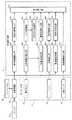
本実施形態に係る運転支援装置の構成について、図1を参照して説明する。図1は、本実施形態に係る運転支援装置1の構成を示すブロック図である。1. 1. Configuration The configuration of the driving support device according to the present embodiment will be described with reference to FIG. FIG. 1 is a block diagram showing a configuration of a driving
図1に示すように、運転支援装置1は、第1センサ群2と、車載機器インタフェース(以下「インタフェース」を「IF」と略記する)20と、行為検知部3と、ドライバ状態検知部4と、解除予告方法決定部5とを備える。また、運転支援装置1は、提示制御部6と、第2センサ群7と、運転モード選択部8と、車両制御部80とを備える。運転支援装置1は、自動運転の対象となる車両に搭載され、車両の走行制御を自動的に行う自動運転モードから、車両がドライバによって運転される手動運転モードへの移行を支援する装置である。 As shown in FIG. 1, the driving
第1センサ群2は、車両のドライバをモニタリングするための各種情報を感知するセンサデバイスの集合である。本実施形態において、第1センサ群2は、車内カメラ21、マイク22、体動センサ23、血圧センサ24及び心拍センサ25を含む。第1センサ群2の各種センサ21〜25及び車載機器IF20は、それぞれ本実施形態におけるセンサ部の一例である。 The
車内カメラ21は、車両の内部を撮像する第1のカメラの一例である。車内カメラ21は、撮像画像を示す画像データを生成する。本実施形態では、一例としてドライバが運転席に居ることを想定している。車内カメラ21は、車両内で運転席近傍を撮像可能に配置される。 The in-
マイク22は、車両内に配置され、周囲の音を収音する。マイク22は、収音した音を示すデータ(オーディオデータ)を生成する。 The
体動センサ23は、例えば運転席の背もたれ或いは座面の内部に配置された荷重センサで構成される。体動センサ23は、運転席に居る者の姿勢の変化を感知し、感知した結果のセンサ信号を生成する。体動センサ23は加速度センサや角速度センサなどで構成されてもよい。 The
血圧センサ24は、ドライバの血圧を測定し、測定結果のセンサ信号を生成する。血圧センサ24は、例えばウェアラブルデバイスで構成され、予め手動運転モード時に運転を行うべき責任者に取り付けられる。 The
心拍センサ25は、ドライバの心拍を測定し、測定結果のセンサ信号を生成する。心拍センサ25は、耳たぶ等の身体に取り付ける接触型のセンサデバイスであってもよいし、脈波に対応した顔色の変化を抽出するカメラなどの非接触型のセンサデバイスであってもよい。 The
車載機器IF20は、有線又は無線通信において車両内の種々の機器との間で各種信号の送受信を行うインタフェース回路(モジュール)である。車載機器IF20は、所定の通信規格に従い通信を行う。所定の規格には、USB、HDMI(登録商標)、IEEE1395、Wi−Fi、Bluetooth(登録商標)等が含まれる。 The in-vehicle device IF20 is an interface circuit (module) that transmits and receives various signals to and from various devices in the vehicle in wired or wireless communication. The in-vehicle device IF20 communicates according to a predetermined communication standard. Predetermined standards include USB, HDMI®, IEEE1395, Wi-Fi, Bluetooth® and the like.
例えば、車載機器IF20は、車両に搭載されたカーナビ−ション装置(以下「カーナビ」という)或いはカーテレビと通信する。また、本実施形態では、車載機器IF20は、例えばドライバが所有するスマートフォン65との情報通信を行う。例えば、スマートフォン65に車載機器IF20との通信のための専用のアプリケーションプログラムをインストールして、無線通信が行われてもよいし、有線接続されてもよい。スマートフォン65に代えて、又はこれに加えて、ゲーム端末、タブレット端末及びノートPCなどの各種携帯情報端末が用いられてもよい。 For example, the in-vehicle device IF20 communicates with a car navigation device (hereinafter referred to as "car navigation") mounted on a vehicle or a car television. Further, in the present embodiment, the in-vehicle device IF20 performs information communication with, for example, a
行為検知部3は、第1センサ群2の各種センサ21〜25及び車載機器IF20からの各種情報に基づき、例えば周期的にドライバの行為を検知する。行為検知部3による行為の検知方法については後述する。 The action detection unit 3 periodically detects, for example, the driver's action based on various information from the
ドライバ状態検知部4は、第1センサ群2の各種センサ21〜25及び車載機器IF20からの各種情報に基づき、例えば周期的にドライバの運転に対する意識に関する複数の状態を検知する。以下、ドライバ状態検知部4によって検知されるドライバの複数の状態を総称して、「ドライバ状態」という。ドライバ状態は、ドライバの生理状態および心理状態を含む。生理状態は、眠気及び疲労などの人間の生理的な要因に基づく状態である。心理状態は、緊張及び集中などの人間の心理的な要因に基づく状態である。 The driver state detection unit 4 periodically detects a plurality of states related to the driver's awareness of driving, for example, based on various information from the
本実施形態では一例として、ドライバ状態検知部4は、それぞれドライバの覚醒度、疲労度、緊張度又は集中度のレベルを検知する覚醒度検知部41、疲労度検知部42、緊張度検知部43及び集中度検知部44を含む。覚醒度及び疲労度は、それぞれドライバの生理状態を表す尺度の一例である。緊張度及び集中度は、それぞれドライバの心理状態を表す尺度の一例である。ドライバ状態検知部4における各種尺度の検知方法については後述する。 In the present embodiment, as an example, the driver state detection unit 4 includes an
行為検知部3及びドライバ状態検知部4は、例えば、一体的に検知部10を構成するように実装される。検知部10は、例えばソフトウェアと協働して所定の機能を実現するCPU等を備え、行為検知部3及びドライバ状態検知部4の各機能を実現する。また、検知部10は、ROM及びRAMなどで構成される内部メモリを備え、行為検知部3及びドライバ状態検知部4としての検知結果を随時、内部メモリに蓄積する。 The action detection unit 3 and the driver state detection unit 4 are implemented so as to integrally constitute the
解除予告方法決定部5は、解除予告方法選択部50及び記憶部55を備える。解除予告方法選択部50は、例えばソフトウェアと協働して所定の機能を実現するCPU等で構成され、解除予告開始時刻算出部51、解除予告提示手段選択部52及び解除予告提示内容選択部53の各機能を実現する(後述)。これにより、解除予告方法選択部50は、ドライバに自動運転モードが解除されることを伝える解除予告を車両内に提示する方法を選択する。 The release notice method determination unit 5 includes a release notice
記憶部55は、解除予告方法決定部5の機能を実現するために必要なプログラム及びデータを記憶する記録媒体であり、ROM及びRAMなどで構成される。記憶部55は、例えば、解除予告方法データベースD1を格納する。解除予告方法データベースD1は、ドライバの行為及び状態と、解除予告を提示する各種方法とを関連付けて管理するデータベースである。解除予告方法決定部5の機能の詳細については後述する。 The
提示制御部6は、例えばソフトウェアと協働して所定の機能を実現するCPU等で構成され、車両内で種々の形式において情報を提示可能な提示手段60を制御する。提示手段60は、カーナビなどの各種車載ディスプレイ61、スピーカ62、ドライバシート63及びスマートフォン65を含む。例えば、提示制御部6は、ドライバシート63に内蔵された振動アクチュエータ或いはシートベルトの振動アクチュエータ等を駆動制御する。 The
また、本実施形態において、提示制御部6は、各種車載ディスプレイ61と共にディスプレイ系統の提示手段60の一つとして、スマートフォン65を制御する。提示制御部6は、例えば車載機器IF20を介して通信を行い、スマートフォン65等の画面における画像表示を制御する。 Further, in the present embodiment, the
第2センサ群7は、車両の外部の状況をモニタリングするための各種情報を感知するセンサデバイスの集合である。第2センサ群7は、例えば、カメラ71、レーダ72及びGPS73などを含む(図9参照)。 The
第2センサ群7のカメラ71は、例えば車両の外面に配置され、車両の外部の環境(例えば周囲の他の車両)を撮像する第2のカメラの一例である。レーダ72は、自車両の周囲に存在する車両或いは障害物までの距離及び位置などを測定する。GPS73は、GPS衛星から自車両の位置を示すGPS情報を受信する。 The camera 71 of the
運転モード選択部8は、例えばソフトウェアと協働して所定の機能を実現するCPU等で構成され、走行状態情報取得部81、道路状況予測部82、自動運転継続判定部83、自動運転解除判定部84及び自動/手動運転切替部85を含む。運転モード選択部8は、第2センサ群7によって得られる諸情報に基づき、車両の走行制御を自動的に行う自動運転モードと、車両がドライバによって運転される手動運転モードのいずれかのモードを選択する。 The operation mode selection unit 8 is composed of, for example, a CPU or the like that realizes a predetermined function in cooperation with software, and includes a driving state
車両制御部80は、例えばソフトウェアと協働して所定の機能を実現するCPU等で構成され、現在選択されている運転モードに基づいて、車両の走行制御を行う。例えば、自動運転モード中では、車両制御部80は、第2センサ群7によって得られる諸情報を用いて、車両において加速、操舵及び制動用の各種アクチュエータ並びにECU等を制御する。 The
以上のように説明した運転支援装置1において、検知部10、解除予告方法決定部5、提示制御部6、運転モード選択部8及び車両制御部80などの各部の各構成要素は、専用のハードウェアで構成されてもよい。また、各構成要素に適したソフトウェアプログラムを実行することによって実現されてもよい。また、各構成要素は、CPUまたはプロセッサなどのプログラム実行部が、ハードディスクまたは半導体メモリなどの記録媒体に記録されたソフトウェアプログラムを読み出して実行することによって実現されてもよい。 In the driving
さらに、上記の各装置を構成する構成要素の一部又は全部は、1個のシステムLSI(Large Scale Integration:大規模集積回路)から構成されてもよい。システムLSIは、複数の構成部を1個のチップ上に集積して製造された超多機能LSIであり、具体的には、マイクロプロセッサ、ROM、及びRAMなどを含んで構成されるコンピュータシステムである。RAMには、コンピュータプログラムが記憶されている。マイクロプロセッサが、コンピュータプログラムに従って動作することにより、システムLSIは、その機能を達成する。 Further, a part or all of the constituent elements constituting each of the above-mentioned devices may be composed of one system LSI (Large Scale Integration: large-scale integrated circuit). A system LSI is an ultra-multifunctional LSI manufactured by integrating a plurality of components on a single chip. Specifically, it is a computer system including a microprocessor, a ROM, a RAM, and the like. is there. A computer program is stored in the RAM. The system LSI achieves its function by operating the microprocessor according to the computer program.
さらにまた、上記の各装置を構成する構成要素の一部又は全部は、各装置に脱着可能なICカード又は単体のモジュールから構成されてもよい。ICカード又はモジュールは、マイクロプロセッサ、ROM、及びRAMなどから構成されるコンピュータシステムである。ICカード又はモジュールは、上記の超多機能LSIを含んでもよい。マイクロプロセッサが、コンピュータプログラムに従って動作することにより、ICカード又はモジュールは、その機能を達成する。このICカード又はこのモジュールは、耐タンパ性を有してもよい。 Furthermore, some or all of the components constituting each of the above devices may be composed of an IC card or a single module that can be attached to and detached from each device. An IC card or module is a computer system composed of a microprocessor, a ROM, a RAM, and the like. The IC card or module may include the above-mentioned super multifunctional LSI. When the microprocessor operates according to a computer program, the IC card or module achieves its function. This IC card or this module may have tamper resistance.
2.動作
以上のように構成された本実施の形態における運転支援装置1の動作について、以下、説明する。2. Operation The operation of the driving
2−1.動作の概要
本実施形態における運転支援装置1の動作の概要について、図1を参照して説明する。本実施形態において、運転支援装置1は、行為検知部3及びドライバ状態検知部4により、運転中のドライバの行為及び当該行為を行うドライバの状態をモニタリングし続ける。また、自動運転モード中には、運転モード選択部8において常時、自動運転が現在時刻から所定時間(例えば1時間)以上、継続可能か否かの判定が、道路状況等に基づき行われる。2-1. Outline of Operation An outline of the operation of the
上記の判定処理において、自動運転が所定時間以上、継続できないと判定されたときには、解除予告方法決定部5が、そのときに検知されたドライバの行為と、当該行為に基づく特定のドライバの状態の検知結果を参照して、自動運転の解除予告を提示する方法を決定する。すると、提示制御部6は、決定された方法に従う開始タイミング、提示手段、提示内容等において、解除予告をドライバに提示する。ここで、特定のドライバの状態とは、ドライバが運転以外の行為から手動運転に確実に復帰できると判定するために必要と考えられるドライバの状態(例えば集中度)のことであり、検知されるドライバの行為に応じて予め設定されている。 In the above determination process, when it is determined that the automatic driving cannot be continued for a predetermined time or longer, the cancellation notice method determination unit 5 determines the driver's action detected at that time and the state of the specific driver based on the action. With reference to the detection result, the method of presenting the cancellation notice of the automatic operation is determined. Then, the
具体的に、ドライバが自動運転モード中に、テレビ視聴又はゲーム行為等をしている場合には、その行為中のドライバの覚醒度だけでなく、その行為に対する集中度に基づいて、解除予告の提示を開始する開始タイミングや提示手段(音、画面等)、提示内容を変更する。例えば、ドライバがうとうとしながらテレビ視聴をしている状態、或いはゲーム等に熱中して画面に極度に集中している状態には、ドライバが手動運転ができる状態になる時間が、通常の状態よりも長く掛かると考えられる。そこで、本実施形態では、通常よりも解除予告の開始タイミングを早くしたり、解除予告を強調するように提示手段及び提示内容を設定したりする。 Specifically, when the driver is watching TV or playing a game while in the automatic driving mode, the cancellation notice is given based not only on the driver's alertness during the action but also on the concentration on the action. Change the start timing, presentation means (sound, screen, etc.) and presentation content to start presentation. For example, when the driver is drowsy watching TV, or when he is absorbed in a game and is extremely focused on the screen, the time for the driver to be able to drive manually is longer than in the normal state. It is thought that it will take a long time. Therefore, in the present embodiment, the start timing of the cancellation notice is earlier than usual, and the presentation means and the presentation contents are set so as to emphasize the cancellation notice.
以上のように、ドライバの行為及び状態に応じて、自動運転の解除予告方法を変更することにより、自動運転モード中に運転から離れているドライバを安全かつ円滑に、手動運転ができる状態に戻し易くすることができる。以下、本実施形態に係る運転支援装置1の動作の詳細について説明する。 As described above, by changing the method of notifying the cancellation of automatic driving according to the driver's actions and conditions, the driver who is away from driving during the automatic driving mode can be returned to a state where manual driving can be performed safely and smoothly. It can be made easier. Hereinafter, the details of the operation of the driving
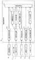
2−2.ドライバの行為の検知方法
行為検知部3によるドライバの行為の検知方法について、図2及び図3を参照して説明する。図2は、運転支援装置1における行為検知部3の機能を例示する機能ブロック図である。図3は、行為検知部3の動作を説明するための図である。2-2. Driver Action Detection Method The driver action detection method by the action detection unit 3 will be described with reference to FIGS. 2 and 3. FIG. 2 is a functional block diagram illustrating the function of the action detection unit 3 in the driving
図2に示すように、行為検知部3は、ドライバが行っていると推定される行為を検知するための行為推定部300を含む。行為検知部3は、第1センサ群2の各種センサ21,22,23からのセンサ信号及び車載機器IF20の出力信号を随時、受信して、運転中のドライバの行為を認識するための各種検知処理を順次、行う。検知処理結果に基づき、行為推定部300は、図3に例示するように、メール、ゲーム及びテレビ視聴などの種々のドライバの行為を検知する。 As shown in FIG. 2, the action detection unit 3 includes an
車載機器IF20は、例えば、カーナビ61a及びスマートフォン65などの通信接続されている機器の操作が為されたときに、操作中の機器及び操作内容を含む操作情報を受信し、操作情報を示す出力信号を生成する。 The in-vehicle device IF20 receives operation information including the device being operated and the operation content when a communication-connected device such as a car navigation system 61a and a
行為検知部3は、図2に示すように、操作機器検出部301及び操作内容検出部302を含む。操作機器検出部301は、車載機器IF20の出力信号に基づき、出力信号に含まれる操作情報が示す機器を検出する。操作内容検出部302は、車載機器IF20の出力信号に基づき、操作情報が示す操作内容を検出する。 As shown in FIG. 2, the action detection unit 3 includes an operation
例えば、ドライバがスマートフォン65においてゲームをしている際に、行為検知部3は、操作機器検出部301においてスマートフォン65を検出し、操作内容検出部302において操作内容がゲームであることを検出する。これにより、行為推定部300は、推定されるドライバの行為として「スマートフォンによるゲーム行為」を検知する。 For example, when the driver is playing a game on the
さらに、行為検知部3は、図2に示すように、上半身画像検出部303、しぐさ認識部304、把持物体認識部305、顔画像抽出部306、及び視線対象検出部307を含む。行為検知部3は、車内カメラ21から撮像画像を示す画像データを受信し、上記の各部において以下のように車内カメラ21の撮像画像に基づく画像認識処理を行う。 Further, as shown in FIG. 2, the action detection unit 3 includes an upper body
上半身画像検出部303は、車内カメラ21からの画像データに基づき、撮像画像におけるドライバの上半身を示す上半身画像を検出する。例えば、ドライバ不在時の撮像画像を示す画像データを予め内部メモリに格納しておき、上半身画像検出部303が当該画像データを読み出して、画像データ間の差分に基づき上半身画像を検出する。 The upper body
しぐさ認識部304は、検出された上半身画像に基づき、行為を行う際のドライバのしぐさを認識するために、例えば上半身画像の輪郭から腕及び手の位置及び向きなどを検出する。ドライバのしぐさは、例えば、機器の画面等を指でタッチしたりボタンを押したりすること、及び物体を把持するように手を動かしたり、腕を動かしたり、食事又は発話のために口を動かしたりすることなどを含む。 The
また、物体を把持するしぐさが検出された場合、把持物体認識部305は、把持された物体を認識するための画像処理を行う。例えば、把持物体認識部305は、上半身画像中の手近傍から把持物体の画像を抽出し、スマートフォン、ゲーム端末及び本などの把持物体の候補として予め格納された画像データを参照し、画像間の類似判定を行う。 Further, when the gesture of gripping the object is detected, the gripping
顔画像抽出部306は、例えば人間の顔に関する特徴量に基づき、検出された上半身画像から顔画像を抽出する。顔画像抽出部306は、撮像画像の画像データ全体から顔画像を抽出してもよい。 The face
視線対象検出部307は、抽出された顔画像から検出した顔の向きや、顔画像から抽出した目の画像から推定した視線方向に基づき、ドライバの視線が向けられた対象を検出する。例えば、視線対象検出部307は、撮像画像全体の画像解析、或いは車内カメラ21の配置に基づく車両内の機器の配置推定などにより、顔の向きや視線の延長上にある物体を検出する。 The line-of-sight
以上の画像認識処理に基づき、行為推定部300は、例えば機器の操作又は視聴行為(車載機器IF20と通信接続していない機器を含む)、本又は書類等を読む行為、或いは食事行為などを検知することができる(図3参照)。 Based on the above image recognition processing, the
さらに、行為検知部3は、図2に示すように、音声検出部308、話者数検出部309、環境音検出部310、及び環境音認識部311を含む。行為検知部3は、マイク22から収音したデータを受信して、上記の各部において以下のように音声・環境音認識処理を行う。 Further, as shown in FIG. 2, the action detection unit 3 includes a
音声検出部308は、マイク22から収音したデータの中で、例えば人間が発声する声の特有の特徴量を抽出し、人間の音声を検出する。話者数検出部309は、例えば検出された音声の特徴量の個人差に基づき、話者の人数を検出する。これにより、人間の音声が検出された場合に、図3に示すように、話者数が一人であればドライバの通話行為を推定でき、話者数が複数人であればドライバと同乗者との会話行為を推定できる。 The
環境音検出部310は、マイク22から収音したデータの中で、所定の特徴量等により人間の音声ではないと判定される音である環境音を検出する。環境音認識部311は、検出された環境音を識別するための処理を行う。例えば、環境音認識部311は、音楽、ラジオの音、食事の咀嚼音、髭剃りシェーバ等の動作音などの環境音の候補として予め格納された環境音データを参照し、環境音データ間の比較判定を行う。 The environmental
さらに、行為検知部3は、図2に示すように、体動情報検出部313を含む。体動情報検出部313は、体動センサ23のセンサ信号に基づき、ドライバの体動を示す体動情報を検出する。これにより、ドライバが種々の行為を行う際に姿勢を変えたりする体動が検出され、ドライバの行為に応じたしぐさの検出精度を向上できる(図3参照)。 Further, the action detection unit 3 includes a body movement
2−3.ドライバ状態の検知方法
以下、ドライバ状態検知部4による各種ドライバ状態の検知方法について説明する。2-3. Driver Status Detection Method Hereinafter, various driver status detection methods by the driver status detection unit 4 will be described.
2−3−1.覚醒度の検知方法
ドライバ状態検知部4の覚醒度検知部41による覚醒度の検知方法について、図4を参照して説明する。図4は、運転支援装置1における覚醒度検知部41の機能を例示する機能ブロック図である。2-3-1. Alertness Detection Method An arousal detection method by the
本実施形態において、覚醒度は、眠気の逆に目が醒めている度合いを示す尺度をいうこととする。即ち、ドライバが眠い場合には、覚醒度が低下することとなる。 In the present embodiment, the arousal level refers to a measure indicating the degree of awakening of the eyes, which is the opposite of drowsiness. That is, when the driver is sleepy, the arousal level is lowered.
覚醒度検知部41は、例えば車内カメラ21による撮像画像の画像解析によってドライバの覚醒度を検知する。覚醒度検知部41は、図4に示すように、顔画像抽出部411、開眼度検出部412、瞬目検出部413、頭部位置検出部414、及び覚醒度推定部410を含む。 The arousal
覚醒度検知部41による画像解析において、まず、顔画像抽出部411は、車内カメラ21からの画像データを随時、取得し、撮像画像中のドライバの顔画像を抽出する。次に、開眼度検出部412は、抽出された顔画像中のまぶたの開き具合を示す開眼度を検出する。ここで、ドライバの眠気が強いほど、まぶたは閉じ気味になり、開眼度は小さくなると考えられる。そこで、覚醒度推定部410は、検出された開眼度が小さいほど覚醒度のレベルが低減するように覚醒度の推定レベルを算出する。 In the image analysis by the
また、ドライバが眠いときには、瞬目1回当たりにまぶたが閉じる閉眼時間が長くなり、瞬目回数は減少すると考えられる。そこで、瞬目検出部413は、所定時間(例えば1分間)分の顔画像に基づき、閉眼時間及び瞬目回数を検出する。覚醒度推定部410は、検出された閉眼時間が長くなるほど覚醒度の推定レベルを低減させると共に、検出された瞬目回数が減少するほど覚醒度の推定レベルを低減させる。 Further, when the driver is sleepy, it is considered that the eyelid closing time becomes longer and the number of blinks decreases for each blink. Therefore, the
また、ドライバが眠いときには、ドライバの頭部位置が不安定になると考えられる。そこで、頭部位置検出部414は、車内カメラ21の撮像画像における抽出された顔画像の位置に基づき、ドライバの頭部位置を検出する。覚醒度推定部410は、所定時間(例えば1分間)分の頭部位置の検出結果に基づき、頭部位置の変動率が大きいほど覚醒度の推定レベルを低減させる。 Also, when the driver is sleepy, it is considered that the position of the driver's head becomes unstable. Therefore, the head
以上の撮像画像の画像解析に加えて、又はこれに代えて、覚醒度検知部41は、車両内の音声解析によって覚醒度を検知してもよい。ドライバが眠っているときには、いびき等の寝息が観測できると考えられる。そこで、覚醒度検知部41は、呼吸音検出部415を含む。呼吸音検出部415は、マイク22から収音したデータにおいてドライバの呼吸音を検出し、検出した呼吸音にいびき等の寝息が含まれるか否かを判断する。覚醒度推定部410は、寝息が含まれると判断される毎に覚醒度の推定レベルを低減させる。 In addition to, or instead of, the image analysis of the captured image, the arousal
また、覚醒度検知部41は、心拍センサ25の測定結果に基づき覚醒度を検知してもよい。人間が眠いときには、心拍変動(HRV)に含まれるHF成分(例えば0.04Hz〜0.15Hz)及びLF成分(例えば0.04Hz〜0.15Hz)において、副交感神経の活動に起因するHF成分が大きくなることが知られている。 Further, the
そこで、覚醒度検知部41は、図4に示すように、心拍変動検出部416及びLF/HF検出部417を含む。心拍変動検出部416は、心拍センサ25のセンサ信号から心拍変動を検出する。LF/HF検出部417は、検出された心拍変動におけるLF成分とHF成分との比(LF/HF比)を検出する。覚醒度推定部410は、検出されたLF/HF比が小さいほど覚醒度の推定レベルを低減させる。 Therefore, as shown in FIG. 4, the
また、覚醒度検知部41は、図4に示すように、体動情報検出部418を含んでもよい。ドライバの体動が頻繁にあるときには、ドライバは覚醒していると考えられる。そこで、体動情報検出部418は、体動センサ23のセンサ信号に基づき、ドライバの体動を示す体動情報を検出する。覚醒度推定部410は、体動情報に基づき体動が多いほど覚醒度の推定レベルを増大させる。 Further, the arousal
また、覚醒度検知部41は、図4に示すように、操作頻度検出部419を含んでもよい。機器の操作が頻繁に為されているときには、ドライバは覚醒していると考えられる。そこで、操作頻度検出部419は、例えば過去1分等の所定時間中の車載機器IF20からの出力信号に含まれる操作情報に基づき、操作頻度を検出する。操作頻度は、所定時間中に機器が操作された頻度である。覚醒度推定部410は、検出された操作頻度が多いほど覚醒度の推定レベルを増大させる。 Further, as shown in FIG. 4, the
なお、以上の説明では、覚醒度推定部410において、開眼度検出部412、瞬目検出部413、頭部位置検出部414、呼吸音検出部415、LF/HF検出部417、操作頻度検出部419、体動情報検出部418のいずれかの検出部の結果に応じて、覚醒度レベルの推定を行う例を説明した。本開示はこれに限定されず、覚醒度推定部410において、上記の各検出部の結果を統合的に判断して覚醒度レベルの推定を行っても良い。 In the above description, in the
2−3−2.疲労度の検知方法
ドライバ状態検知部4の疲労度検知部42による疲労度の検知方法について、図5を参照して説明する。図5は、運転支援装置1における疲労度検知部42の機能を例示する機能ブロック図である。2-3-2. Fatigue Detection Method A fatigue detection method by the
本実施形態において、疲労度は、身体的な疲労の溜まり具合を示す尺度をいうこととする。 In the present embodiment, the degree of fatigue refers to a measure indicating the degree of accumulation of physical fatigue.
疲労度検知部42は、例えば心拍センサ25の測定結果に基づき疲労度を検知する。疲労度検知部42は、図5に示すように、心拍数検出部421、心拍変動検出部422、LF/HF検出部423、及び疲労度推定部420を含む。 The fatigue
心拍数検出部421は、心拍センサ25のセンサ信号に基づき心拍数(HR)を検出する。ドライバに疲労が溜まっているときには、心拍数が安静時の平均心拍数からずれることが考えられる。そこで、疲労度推定部420は、検出された心拍数と予め設定された心拍数の基準値との差分が大きいほど疲労度が大きく推定されるように疲労度の推定レベルを算出する。 The heart
また、疲労度検知部42の心拍変動検出部422及びLF/HF検出部423は、それぞれ覚醒度検知部41の例と同様に心拍変動及びLF/HF比を検出する。ドライバに疲労が溜まっているときには、心拍変動において交感神経の活動に起因するLF成分が大きくなると考えられる。そこで、疲労度推定部420は、検出されたLF/HF比が大きくなるほど疲労度の推定レベルを増大させる。 Further, the heart rate
また、図5に示すように、疲労度検知部42は、覚醒度検知部41と同様に体動情報を検出する体動情報検出部424を含んでもよい。ドライバに疲労が溜まっているときには、身体的なストレスを軽減するため、座り直し等の姿勢変化を頻繁に行うようになり、体動が多くなると考えられる。そこで、疲労度推定部420は、検出される体動情報に基づき体動が多いほど疲労度の推定レベルを増大させる。 Further, as shown in FIG. 5, the fatigue
また、疲労度検知部42は、図5に示すように、操作頻度検出部425及び誤操作検出部426を含んでもよい。疲労度検知部42の操作頻度検出部425は、覚醒度検知部41の操作頻度検出部419と同様に、車載機器IF20からの操作情報に基づき操作頻度を検出する。誤操作検出部426は、車載機器IF20からの操作情報に含まれる操作内容に基づき誤操作頻度を検出する。誤操作頻度は、所定時間中に為された操作の内の誤操作の頻度である。 Further, as shown in FIG. 5, the fatigue
本実施形態では、ドライバが自動運転モード中に運転以外の行為を行うことによって疲労が生じることを想定している。例えば、ドライバがスマートフォンなどの操作を行っている際に疲労が生じたときには、操作頻度が減り、誤操作頻度は増えると考えられる。そこで、疲労度推定部420は、検出された操作頻度が減少するほど疲労度の推定レベルを増大させ、検出された誤操作頻度が増大するほど疲労度の推定レベルを増大させる。 In the present embodiment, it is assumed that fatigue is caused by the driver performing an action other than driving during the automatic driving mode. For example, when fatigue occurs while the driver is operating a smartphone or the like, it is considered that the frequency of operation decreases and the frequency of erroneous operation increases. Therefore, the fatigue
なお、以上の説明では、疲労度推定部420において、心拍数検出部421、心拍変動検出部422、LF/HF検出部423、体動情報検出部424、操作頻度検出部425及び誤操作検出部426のいずれかの検出部の結果に応じて、疲労度レベルの推定を行う例を説明した。本開示はこれに限定されず、疲労度推定部420において、上記の各検出部の結果を統合的に判断して疲労度レベルの推定を行っても良い。 In the above description, in the fatigue
2−3−3.緊張度の検知方法
ドライバ状態検知部4の緊張度検知部43による緊張度の検知方法について、図6を参照して説明する。図6は、運転支援装置1における緊張度検知部43の機能を例示する機能ブロック図である。2-3-3. Tension detection method A tension detection method by the
本実施形態において、緊張度は、対象の人間が緊張(又は興奮)している度合いを示す尺度をいうこととする。 In the present embodiment, the degree of tension refers to a measure of the degree of tension (or excitement) of the target person.
緊張度検知部43は、例えば血圧センサ24の測定結果に基づき緊張度を検知する。緊張度検知部43は、図6に示すように、血圧検出部431、及び緊張度推定部430を含む。 The
血圧検出部431は、血圧センサ24のセンサ信号に基づき、ドライバの血圧を検出する。人間は緊張していると、血圧が高くなる傾向がある。そこで、緊張度推定部430は、検出された血圧に基づき、検出された血圧が大きいほど緊張度が大きく推定されるように緊張度の推定レベルを算出する。 The blood
また、図6に示すように、緊張度検知部43は、疲労度検知部42の例と同様にそれぞれ心拍数、心拍変動及びLF/HF比を検出する心拍数検出部432、心拍変動検出部433及びLF/HF検出部434を含んでもよい。 Further, as shown in FIG. 6, the
人間は緊張していると、心拍数が高くなる傾向がある。そこで、緊張度推定部430は、検出された心拍数が高くなるほど緊張度の推定レベルを増大させる。また、人間は緊張していると、心拍変動におけるLF成分が大きくなる傾向がある。そこで、緊張度推定部430は、検出されたLF/HF比が大きいほど緊張度の推定レベルを増大させる。 When humans are tense, their heart rate tends to be high. Therefore, the
また、図6に示すように、緊張度検知部43は、疲労度検知部42の例と同様に誤操作頻度を検出する誤操作検出部435を含んでもよい。ドライバがスマートフォンなどの操作を行っている際に緊張していると、誤操作頻度が増えると考えられる。そこで、緊張度推定部430は、検出された誤操作頻度が増大するほど緊張度の推定レベルを増大させる。 Further, as shown in FIG. 6, the
なお、以上の説明では、緊張度推定部430において、血圧検出部431、心拍数検出部432、心拍変動検出部433、LF/HF検出部434、及び誤操作検出部435のいずれかの検出部の結果に応じて、緊張度レベルの推定を行う例を説明した。本開示はこれに限定されず、緊張度推定部430において、上記の各検出部の結果を統合的に判断して緊張度レベルの推定を行っても良い。 In the above description, in the
2−3−4.集中度の検知方法
ドライバ状態検知部4の集中度検知部44による集中度の検知方法について、図7を参照して説明する。図7は、運転支援装置1における集中度検知部44の機能を例示する機能ブロック図である。2-3-4. Concentration Detection Method The concentration detection method by the
本実施形態において、集中度は、対象の人間が行っている行為に対する集中力の度合いを示す尺度をいうこととする。 In the present embodiment, the degree of concentration refers to a measure of the degree of concentration on the actions performed by the target person.
集中度検知部44は、例えば車内カメラ21による撮像画像の画像解析によって集中度を検知する。集中度検知部44は、図7に示すように、顔画像抽出部441、視線挙動検出部442、及び集中度推定部440を含む。集中度検知部44の顔画像抽出部441は、覚醒度検知部41の例と同様に顔画像を抽出する。 The
視線挙動検出部442は、例えば過去1分等の所定時間中に抽出された顔画像における目の位置を特定し、視線の挙動すなわち視線の移動率を検出する。特定の行為に対するドライバの集中力が高まっているときには、ドライバは行為の対象(例えばゲーム端末の画面等)を注視し、視線の移動が少なくなると考えられる。そこで、集中度推定部440は、検出された視線の移動率が低い程、増大させるように集中度のレベルを算出する。 The line-of-sight
また、図7に示すように、集中度検知部44は、視線挙動検出部442に加えて、又はこれに代えて、覚醒度検知部41の例と同様に開眼度を検出する開眼度検出部443、及び/又は覚醒度検知部41の例と同様に瞬目回数を検出する瞬目回数検出部444を含んでもよい。ドライバの集中力が高まっているときには、開眼度が大きくなり、瞬目回数は減少すると考えられる。そこで、集中度推定部440は、検出された開眼度が大きいほど、及び/又は検出された瞬目回数が多いほど、集中度の推定レベルを増大させる。 Further, as shown in FIG. 7, the
また、図7に示すように、集中度検知部44は、疲労度検知部42の例と同様に操作頻度を検出する操作頻度検出部445、及び/又は誤操作頻度を検出する誤操作頻度検出部446を含んでもよい。例えば、ゲームをしているドライバの集中力が高まっているときには、ゲーム端末等の操作頻度が高くなり、誤操作頻度は低くなると考えられる。そこで、集中度推定部440は、検出された操作頻度が高いほど、及び/又は検出された誤操作頻度が低いほど、集中度の推定レベルを増大させる。 Further, as shown in FIG. 7, the
また、図7に示すように、集中度検知部44は、疲労度検知部42の例と同様に心拍数を検出する心拍数検出部447を含んでもよい。ドライバの集中力が高まっているときには、特にドライバの行為に拘わらず、心拍数が平常時よりも大きくなると考えられる。そこで、集中度推定部440は、検出された心拍数が高いほど、集中度の推定レベルを増大させる。 Further, as shown in FIG. 7, the
なお、以上の説明では、集中度推定部440において、顔画像抽出部441、視線挙動検出部442、開眼度検出部443、瞬目回数検出部444、操作頻度検出部445、誤操作頻度検出部446、及び心拍数検出部447のいずれかの検出部の結果に応じて、集中度レベルの推定を行う例を説明した。本開示はこれに限定されず、集中度推定部440において、上記の各検出部の結果を統合的に判断して集中度レベルの推定を行っても良い。 In the above description, in the
2−4.自動運転モードの解除処理について
自動運転モードを解除する際に実行される解除処理について、図1及び図8を参照して説明する。図8は、運転支援装置1による自動運転モードの解除処理を説明するためのフローチャートである。2-4. About the release process of the automatic operation mode The release process executed when the automatic operation mode is released will be described with reference to FIGS. 1 and 8. FIG. 8 is a flowchart for explaining the process of canceling the automatic operation mode by the
図8に示すフローチャートは、運転支援装置1において、自動運転モード中に実行される。また、本処理の実行中に、行為検知部3及びドライバ状態検知部4は、それぞれ上記の検知動作を繰り返していることとする。 The flowchart shown in FIG. 8 is executed in the driving
まず、運転支援装置1の運転モード選択部8(図1)において、道路状況予測部82は、走行状態情報取得部81からの走行状態情報に基づき、道路状況の予測処理を行う(S1)。例えば、道路状況予測部82は、自車両が高速道路を走行している状況下で、高速道路の出口に到達するまでの期間の予測を行う。走行状態情報は、自車両が走行する走行状態および自車両の周囲の環境を示す情報である。走行状態情報の取得方法については、後述する。 First, in the driving mode selection unit 8 (FIG. 1) of the driving
次に、自動運転継続判定部83は、道路状況の予測結果及び走行状態情報に基づいて、現在時刻から所定時間以上、自動運転モードが継続可能か否かを判定する(S2)。所定時間は、解除予告の開始タイミングを最大限早めることが可能なマージンを考慮して設定される時間、即ち、運転タスクから離れていたドライバを、ある程度の余裕をもって、手動運転が行えるような状態に戻すことが可能と思われる時間であり、例えば10分間である。 Next, the automatic driving
自動運転モードが継続可能であると判定されたとき(S2でYes)、運転モード選択部8は、所定の周期(例えば1分)においてステップS1以降の処理を繰り返す。 When it is determined that the automatic operation mode can be continued (Yes in S2), the operation mode selection unit 8 repeats the processes after step S1 in a predetermined cycle (for example, 1 minute).
一方、自動運転モードが継続可能でないと判定されたとき(S2でNo)、解除予告方法決定部5の解除予告方法選択部50は、そのときに行為検知部3によって検知された行為、及びドライバ状態検知部4によって検知されたドライバ状態を示す情報を取得する。解除予告方法決定部5は、取得した行為及びドライバ状態の検知結果に基づいて、解除予告方法を決定する(S3)。 On the other hand, when it is determined that the automatic operation mode cannot be continued (No in S2), the release notice
解除予告方法は、車両内において解除予告を提示する方法である。ステップS3において、解除予告方法選択部50の解除予告開始時刻算出部51は、解除予告を提示する開始タイミングを算出し、例えば提示制御部6に設定する。また、解除予告提示手段選択部52は、提示手段60の中の、解除予告を提示する提示手段を選択し、提示制御部6に設定する。また、解除予告提示内容選択部53は、解除予告において提示する提示内容を選択し、提示制御部6に設定する。解除予告方法の決定処理の詳細については後述する。 The cancellation notice method is a method of presenting a cancellation notice in the vehicle. In step S3, the release notice start
次に、提示制御部6は、現在時刻が設定された開始タイミングに到達したか否かを判定する(S4)。提示制御部6は、現在時刻が設定された開始タイミングに到達するまで本ステップを繰り返す。 Next, the
現在時刻が設定された開始タイミングに到達すると(S4でYes)、提示制御部6は、解除予告方法決定部5で決定された解除予告方法に従って、選択された内容の解除予告が選択された提示手段に提示されるように、解除予告の提示を制御する(S5)。 When the start timing at which the current time is set is reached (Yes in S4), the
次に、運転モード選択部8における自動運転解除判定部84は、解除予告の提示後のドライバの行為及ドライバ状態の検知結果に基づいて、ドライバが手動運転可能か否かを判定する(S6)。本処理は、例えば、ドライバが運転以外の行為を止めたか、視線が車両前方に向いているかなどを判定することによって行われる。この際、過度に覚醒度等が低すぎないか等、適宜、生理/心理状態の検知結果が用いられてもよい。 Next, the automatic operation
ドライバが手動運転可能でないと判定された場合(S6でNo)、解除予告方法決定部5は、再度、解除予告方法を決定する(S3)。この場合、再度の解除予告であることを考慮して、適宜、解除予告方法の再設定がなされる。 When it is determined that the driver cannot be manually operated (No in S6), the release notice method determining unit 5 determines the release notice method again (S3). In this case, the cancellation notice method is reset as appropriate in consideration of the cancellation notice again.
一方、ドライバが手動運転可能であると判定された場合(S6でYes)、自動/手動運転切替部85は、自動運転モードを解除して手動運転モードに切り替えるように、車両制御部80を制御する(S7)。すると、車両制御部80は、車両の自動的な運転制御を解除する。 On the other hand, when it is determined that the driver can drive manually (Yes in S6), the automatic / manual
これにより、車両の運転はドライバによる手動運転に移行し、運転支援装置1は、図8のフローチャートの処理を終了する。 As a result, the driving of the vehicle shifts to the manual driving by the driver, and the driving
以上の処理によると、自動運転モードから手動運転モードへの移行時に、自動運転中のドライバの行為及び、その行為に対するドライバの生理/心理状態に応じて、解除予告方法が変更される。これにより、ドライバを安全かつ円滑に手動運転に復帰させることができる。 According to the above processing, at the time of transition from the automatic driving mode to the manual driving mode, the cancellation notice method is changed according to the driver's action during automatic driving and the physiological / psychological state of the driver for the action. As a result, the driver can be safely and smoothly returned to manual operation.
以上の説明では、ステップS3の決定処理に続いて、提示制御部6が、現在時刻が設定された開始タイミングに到達するまでステップ4の判定処理を繰り返す例について説明した。これに限らず、例えば現在時刻が設定された開始タイミングに到達するまでに、ドライバの行為及び状態が変化することも考えられる。このため、例えば、ステップS4において「No」の判定が為されたときに、解除予告方法決定部5は、行為検知部3及びドライバ状態検知部4の新たな検知結果を確認してもよい。この際にドライバの行為及び状態に変化が確認された場合には、解除予告方法決定部5は、決定された解除予告方法による種々の設定を適宜、更新してもよい。 In the above description, following the determination process in step S3, the
また、以上の説明では、ステップS6において、自動運転解除判定部84によってドライバが手動運転可能でないと判定された場合(S6でNo)、解除予告方法決定部5は、再度、解除予告方法を決定した(S3)。ステップS6において所定回数以上「No」の判定が繰り返された場合には、本フローチャートによる処理を終了してもよい。この際、車両制御部80は、例えば車両を安全な位置に停車するように、運転制御を行ってもよい。 Further, in the above description, when the automatic operation
2−4−1.走行状態情報の取得方法について
図8のフローチャートのステップS1における走行状態情報の取得方法について、図9を参照して説明する。図9は、走行状態情報取得部81の機能を例示する機能ブロック図である。2-4-1. About the acquisition method of the running state information The method of acquiring the running state information in step S1 of the flowchart of FIG. 8 will be described with reference to FIG. FIG. 9 is a functional block diagram illustrating the function of the traveling state
図9に示すように、走行状態情報取得部81は、車両走行位置算出部811、地図データ記憶部812、車両走行情報取得部813、周囲環境情報取得部814、及び交通情報取得部815を含む。また、第2センサ群7は、カメラ71、レーダ72、及びGPS73を含む。また、車両には、インターネット等のネットワークに無線接続可能な通信モジュールである無線通信部11が備え付けられていることとする。 As shown in FIG. 9, the traveling state
走行状態情報取得部81は、第2センサ群7におけるGPS73からGPS情報を取得する。地図データ記憶部812は、予め地図データを記憶している。車両走行位置算出部811は、取得されたGPS情報に基づき、地図データ記憶部812に記憶された地図データにおける自車両の走行位置を算出する。 The traveling state
車両走行情報取得部813は、車両制御部80が走行制御する自車両の走行速度などを示す車両走行情報を取得する。 The vehicle travel
道路状況予測部82は、例えば自動運転モードにおいて高速道路の走行中に、図8のステップS1において、走行位置情報、地図データ及び車両走行情報に基づき、自車両が高速道路の出口に到達するまでの予測時間を算出する。この場合、図8のステップS2において、自動運転継続判定部83は、予測時間と予め設定された所定時間(2−4参照)とを比較し、予測時間が所定時間未満になると「No」に進む。 The road
周囲環境情報取得部814は、カメラ71から自車両の外部の環境の撮像画像を示す画像データを取得する。また、周囲環境情報取得部814は、レーダ72による測定情報を取得してもよい。カメラ71からの画像データ、及びレーダ72による測定情報は、それぞれ自車両の周囲に存在する他の車両の状況を示す情報を含む周囲環境情報の一例である。 The surrounding environment
交通情報取得部815は、無線通信部11から交通情報を取得する。交通情報は、インターネット等に公開された渋滞箇所及び渋滞規模などのリアルタイムの交通状況を示す情報である。 The traffic
周囲環境情報取得部814によって取得された周囲環境情報と、交通情報取得部815によって取得された交通情報等に基づき、道路状況予測部82は、例えば上記所定時間内の自車両の周囲の車両の交通状況を予測する。例えば自車両が、所定時間内に、渋滞箇所を通過するか否かを予測する。自動運転継続判定部83は、道路状況予測部82の予測結果に基づき、現在時刻から所定時間以上、自動運転モードが継続可能か否かを、即ち、自動運転システムが機能限界に陥るか否かを判定する。 Based on the surrounding environment information acquired by the surrounding environment
2−4−2.解除予告方法の決定処理について
図8のフローチャートのステップS3における解除予告方法の決定処理について、図10〜図13を参照して説明する。2-4-2. Determining process of release notice method The process of determining the release notice method in step S3 of the flowchart of FIG. 8 will be described with reference to FIGS. 10 to 13.
図10は、行為状態テーブルD2の一例を示す。図8のステップS3において、解除予告方法決定部5は、例えば行為状態テーブルD2を参照し、ドライバ状態を表す各種尺度の中から解除予告方法を決定するために用いる尺度を選択する。行為状態テーブルD2は、ドライバの行為と、ドライバの行為に応じて考慮すべきドライバ状態の尺度とを関連付けて記録するデータテーブルである。 FIG. 10 shows an example of the action state table D2. In step S3 of FIG. 8, the release notice method determination unit 5 refers to, for example, the action state table D2, and selects a scale to be used for determining the release notice method from various scales representing the driver state. The action state table D2 is a data table that records the driver's actions in association with and records the driver state measures to be considered according to the driver's actions.
図10に例示する行為状態テーブルD2は、検知対象の行為と、覚醒度、疲労度、緊張度及び集中度とを関連付けている。検知対象の行為は、メール、SNS、WEB閲覧、ゲーム、テレビ視聴、読書、音楽聴取、ラジオ聴取、会話、通話、食事、及び身繕い(髭剃り、化粧等)を含む。解除予告方法選択部50は、図8のステップS3において、行為検知部3によって検知された行為に基づき、行為状態テーブルD2において「○」に設定された尺度を選択する。 The action state table D2 illustrated in FIG. 10 associates the action to be detected with the alertness, fatigue, tension, and concentration. Actions to be detected include e-mail, SNS, WEB browsing, games, watching TV, reading, listening to music, listening to radio, talking, talking, eating, and grooming (shaving, makeup, etc.). In step S3 of FIG. 8, the release notice
図10の例の行為状態テーブルD2において、例えば、集中度は、メール、SNS、WEB閲覧、ゲーム、テレビ視聴、食事及び身繕いといった行為に対して「○」に設定されている。これは、ドライバが上記の行為に集中した場合、ドライバの視線が特定の対象(例えばゲーム中のゲーム画面)に奪われて、自車両の周囲環境のチェック等をほとんど行わなくなり、手動運転に復帰するまでにより時間が掛かると考えられるためである。 In the action state table D2 of the example of FIG. 10, for example, the degree of concentration is set to "○" for actions such as mail, SNS, WEB browsing, games, watching TV, eating, and grooming. This is because when the driver concentrates on the above actions, the driver's line of sight is taken away by a specific target (for example, the game screen during the game), the surrounding environment of the own vehicle is hardly checked, and the driver returns to manual driving. This is because it is considered that it will take more time to do so.
また、通話などの行為においても、ドライバが緊張するような心理状態の場合、手動運転に復帰するまでに時間が掛かると考えられる。そこで、図10の例で挙げた各行為に対して、緊張度が「○」に設定されている。 In addition, even in an act such as a telephone call, if the driver is in a nervous state, it is considered that it takes time to return to the manual operation. Therefore, the degree of tension is set to "◯" for each of the actions given in the example of FIG.
また、ドライバの行為によっては、行為を行うことによって疲労が生じたり、眠気が生じたりすることが想定される。そこで、疲労度及び覚醒度は、図10に例示するような特定の行為が検知された場合に、「○」に設定されている。 In addition, depending on the driver's actions, it is assumed that the actions may cause fatigue or drowsiness. Therefore, the degree of fatigue and the degree of arousal are set to "◯" when a specific action as illustrated in FIG. 10 is detected.
解除予告方法決定部5は、行為検知部3によって検知された行為に基づき上記のように選択した尺度の組み合わせの各推定レベルをドライバ状態検知部4から取得し、解除予告方法データベースD1を参照して解除予告方法を決定する。 The release notice method determination unit 5 acquires each estimated level of the combination of scales selected as described above based on the action detected by the action detection unit 3 from the driver state detection unit 4, and refers to the release notice method database D1. To determine the cancellation notice method.
図11は、解除予告方法データベースD1の一例を示す。解除予告方法データベースD1は、ドライバの行為と、ドライバ状態と、解除予告の提示方法とを関連付けて管理する。図11では、ドライバの行為がメール、SNS、WEB閲覧、ゲーム及びテレビ視聴、並びに読書である場合の解除予告方法データベースD1を例示している。この場合、覚醒度、疲労度、緊張度及び集中度に応じて、解除予告方法が決定される(図10参照)。 FIG. 11 shows an example of the cancellation notice method database D1. The release notice method database D1 manages the driver's actions, the driver state, and the release notice presentation method in association with each other. FIG. 11 illustrates the release notice method database D1 when the driver's actions are e-mail, SNS, WEB browsing, games and TV viewing, and reading. In this case, the release notice method is determined according to the alertness, fatigue, tension, and concentration (see FIG. 10).
また、図11に例示する解除予告方法データベースD1は、一例として「低」、「中」、「高」の三段階で各種ドライバ状態を分類し、対応する解除予告方法を管理している。解除予告方法決定部5は、ドライバ状態検知部4から取得した各推定レベルをそれぞれ二つのしきい値レベルと比較し、各種ドライバ状態の「低」、「中」、「高」を判定する。 Further, the release notice method database D1 illustrated in FIG. 11 classifies various driver states into three stages of "low", "medium", and "high" as an example, and manages the corresponding release notice method. The release notice method determination unit 5 compares each estimated level acquired from the driver state detection unit 4 with two threshold levels, and determines “low”, “medium”, and “high” of various driver states.
図11の例では、覚醒度、疲労度、緊張度及び集中度の全てが「中」の場合が、ドライバの平常な状態を表すドライバ状態である。この場合、解除予告方法決定部5の解除予告提示内容選択部53は、解除予告の提示内容を「手動運転に切り替わることの通知」に設定する。また、解除予告提示手段選択部52は、ディスプレイ系統及びスピーカ系統を提示手段に採用する。これにより、図11に示すように、解除予告において上記の通知内容が、カーナビ61a等の所定の画面に表示されたり、音声出力されたりする。 In the example of FIG. 11, when all of the alertness, fatigue, tension, and concentration are "medium", it is the driver state indicating the normal state of the driver. In this case, the cancellation notice presentation
また、上記の場合において、解除予告開始時刻算出部51は、通常時の解除予告の開始タイミングとして、手動運転への切替えの予想時刻よりも所定の引継時間前のタイミングを算出する。引継時間は、例えば行為ごとにドライバが手動運転に復帰するまでに必要と予想される時間に設定される。解除予告の開始タイミングの算出方法について、図12及び13を用いて説明する。 Further, in the above case, the cancellation notice start
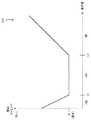
図12のグラフは、覚醒度、疲労度及び緊張度が「中」の場合の集中度と解除予告の開始タイミングとの関係を示す。L1,L2は、集中度の三段階(「低」、「中」、「高」)を判定するためのしきい値レベルを示す。t0は、通常時の解除予告の開始タイミングを示す。図13のグラフは、覚醒度、疲労度及び集中度が「中」の場合の緊張度と解除予告の開始タイミングとの関係を示す。L11,L12は、緊張度の三段階を判定するためのしきい値レベルを示す。 The graph of FIG. 12 shows the relationship between the degree of concentration and the start timing of the release notice when the degree of arousal, the degree of fatigue, and the degree of tension are “medium”. L1 and L2 indicate the threshold level for determining the three levels of concentration (“low”, “medium”, and “high”). t0 indicates the start timing of the cancellation notice at the normal time. The graph of FIG. 13 shows the relationship between the tension level and the start timing of the release notice when the alertness level, fatigue level, and concentration level are “medium”. L11 and L12 indicate the threshold level for determining the three levels of tension.
解除予告方法決定部5の記憶部55は、図12及び図13のグラフに対応する情報D31,D32を、各種ドライバ状態の「低」、「中」、「高」の分類毎に予め記憶している。 The
覚醒度、疲労度及び緊張度が「中」の場合、解除予告開始時刻算出部51は、図12のグラフに対応する情報D31を参照し、ドライバ状態検知部4によって検出された集中度の推定レベルに対応する開始タイミングを算出する。これにより、集中度が「高」の場合には集中度が高いほど、開始タイミングが通常のタイミングt0よりも早くなる。このため、ゲーム等の行為に対するドライバの集中度が高いほど早いタイミングに解除予告が提示され、ドライバが手動運転に安全に復帰し易くなる。 When the arousal level, the fatigue level, and the tension level are "medium", the release notice start
また、ドライバの集中力が散漫な場合にも、手動運転に復帰するまでに時間が掛かることが考えられる。このため、図12の例において、解除予告の開始タイミングは、集中度が「低」の場合には集中度が低いほど早くなるように設定されている。 Further, even when the driver's concentration is distracted, it may take time to return to the manual operation. Therefore, in the example of FIG. 12, the start timing of the cancellation notice is set so that when the degree of concentration is "low", the lower the degree of concentration, the earlier.
また、覚醒度、疲労度及び集中度が「中」であって緊張度が「高」の場合、解除予告開始時刻算出部51は、図13のグラフに対応する情報D32を参照し、緊張度の推定レベルに対応する開始タイミングを算出する。これにより、ドライバの緊張度が高いほど早いタイミングに解除予告が提示され、ドライバが手動運転に安全に復帰し易くなる。 When the alertness, fatigue, and concentration are "medium" and the tension is "high", the release notice start
図11に戻り、覚醒度が「中〜高」、疲労度が「低〜高」、緊張度が「中〜高」、集中度が「高」の場合、解除予告提示内容選択部53は、解除予告の提示内容を「行為の中止を促す警告」に設定する。解除予告提示手段選択部52は、図11に示すように、警告内容の解除予告を、ディスプレイ系統において特定の画面に表示したり、スピーカ系統から音声出力したりすることを決定する。また、より効果的にドライバに警告するために、解除予告提示手段選択部52は、アクチュエータ系統の提示手段において、ドライバの身体を揺らすようにシートを振動させることを決定する。 Returning to FIG. 11, when the alertness is “medium to high”, the fatigue is “low to high”, the tension is “medium to high”, and the concentration is “high”, the cancellation notice presentation
ここで、ドライバがメール、SNS、WEB閲覧、ゲーム及びテレビ視聴といった行為に集中していると、ドライバの視線は視聴中の画面に集まっていると考えられる。そこで、解除予告提示手段選択部52は、ドライバの行為の検知結果に基づき、図11に示すように、ディスプレイ系統の提示手段として視聴中の画面(例えばメール中のスマートフォン、或いはテレビ視聴中のカーテレビ)を選択する。一方、ドライバの行為が読書である場合、本実施形態では図11に示すように、カーナビ61aの画面をディスプレイ系統の提示手段としている。 Here, if the driver concentrates on actions such as e-mail, SNS, WEB browsing, games, and watching TV, it is considered that the driver's line of sight is focused on the screen being watched. Therefore, based on the detection result of the driver's action, the release notice presenting means
また、覚醒度が「低」、疲労度が「低〜高」、緊張度が「低〜中」、集中度が「低」の場合、解除予告提示内容選択部53は「覚醒を促す内容」を提示内容に設定する。解除予告提示手段選択部52は、図11に示すように、ディスプレイ系統による上記内容の表示に加えて、スピーカ系統からの警告音声あるいは警報の出力、及びアクチュエータ系統によるシートの振動あるいはエアコンから冷風を送風すること等を決定する。また、上記の場合において、解除予告開始時刻算出部51は、例えば覚醒度の推定レベルに基づき解除予告の開始タイミングを早めるタイミングを算出する。 When the arousal level is "low", the fatigue level is "low to high", the tension level is "low to medium", and the concentration level is "low", the cancellation notice presentation
3.効果等
以上説明したように、本実施形態に係る運転支援装置1は、車両の走行制御を自動的に行う自動運転モードから、車両がドライバによって運転される手動運転モードへの移行を支援する。運転支援装置1は、行為検知部3と、ドライバ状態検知部4と、解除予告方法決定部5とを備える。行為検知部3は、自動運転モードによる運転中のドライバの行為を検知する。ドライバ状態検知部4は、運転中のドライバの複数の状態を検知する。解除予告方法決定部5は、ドライバに自動運転モードが解除されることを伝える解除予告を車両内に提示する方法を決定する。具体的には、解除予告方法決定部5は、自動運転モードが解除される前に、行為検知部3によって検知されたドライバの行為、及びドライバ状態検知部4によって検知された複数の状態に基づいて、解除予告を提示する方法である解除予告方法を提示制御部6に設定する。3. 3. Effects, etc. As described above, the driving
以上の運転支援装置1によると、ドライバの行為及び当該行為に対するドライバの状態に応じて解除予告方法が設定される。これにより、自動運転モードからドライバによる手動運転モードへの移行時に、ドライバが手動運転に復帰し易くすることができる。 According to the above-mentioned
例えば、提示手段や提示を開始するタイミングを、ドライバの行為だけでなく、その行為に対するドライバの生理/心理状態に基づいて適切に変更することが可能となる。例えば、ドライバがゲーム行為等に対し、非常に集中している場合には、集中していない場合に比べて、ドライバが手動運転を確実に行えるようになるために必要な時間が長く掛かると考えられる。本構成では、ドライバ状態検知部4の検知結果に基づき、ドライバのゲーム行為に対する集中度に応じて、解除予告を提示するタイミングを変えることができるので、ドライバが手動運転を確実に行えるようにすることが可能となる。 For example, it is possible to appropriately change the presentation means and the timing at which the presentation is started based not only on the driver's action but also on the driver's physiological / psychological state for the action. For example, if the driver is very focused on the game, it will take longer for the driver to be able to drive manually than if he is not. Be done. In this configuration, the timing of presenting the cancellation notice can be changed according to the degree of concentration of the driver on the game action based on the detection result of the driver state detection unit 4, so that the driver can reliably perform manual driving. It becomes possible.
また、本実施形態において、解除予告方法決定部5(解除予告方法選択部50)は、検知されたドライバの行為に基づく特定のドライバ状態の検知結果(例えば、集中度が高い等)に応じて解除予告方法を変更し、解除予告方法を提示制御部6に設定する。これにより、ドライバを運転以外の行為から、安全かつ円滑に、手動運転に復帰させることができる。 Further, in the present embodiment, the release notice method determination unit 5 (release notice method selection unit 50) responds to the detection result of a specific driver state (for example, high concentration) based on the detected driver action. The cancellation notice method is changed, and the cancellation notice method is set in the
また、本実施形態において、ドライバ状態検知部4は、ドライバの複数の状態を表す複数の尺度のレベルをそれぞれ検知する。解除予告方法決定部5は、複数の尺度のレベルの中で、検知されたドライバの行為に応じた組み合わせの尺度のレベルの検知結果に基づいて、解除予告方法を設定する(図10参照)。これにより、ドライバの行為に応じた種々の組み合わせの尺度のレベルに基づき、適切に解除予告方法が設定される。 Further, in the present embodiment, the driver state detection unit 4 detects the levels of a plurality of scales representing a plurality of states of the driver. The release notice method determination unit 5 sets the release notice method based on the detection result of the level of the combination of the detected actions of the driver among the levels of the plurality of scales (see FIG. 10). As a result, the cancellation notice method is appropriately set based on the level of various combinations of scales according to the driver's actions.
また、本実施形態において、上記複数の状態は、ドライバの集中度によって表される心理状態を含む。これにより、ドライバの集中度を考慮して解除予告方法を設定することができる。 Further, in the present embodiment, the plurality of states include a psychological state represented by the degree of concentration of the driver. As a result, the release notice method can be set in consideration of the degree of concentration of the driver.
また、本実施形態において、ドライバ状態検知部4は、ドライバの集中度のレベルを検知する。解除予告方法決定部5は、検知されたドライバの行為が特定の行為に該当する場合に、検知された集中度のレベルに応じて解除予告の提示内容を強調するように解除予告方法を設定する。これにより、ドライバの特定の行為に対する集中度が高いほど解除予告の提示内容が強調され、ドライバが手動運転に復帰し易くなる。 Further, in the present embodiment, the driver state detection unit 4 detects the level of concentration of the driver. The cancellation notice method determination unit 5 sets the cancellation notice method so as to emphasize the presentation content of the cancellation notice according to the detected concentration level when the detected driver's action corresponds to a specific action. .. As a result, the higher the concentration of the driver on a specific action, the more emphasized the content of the cancellation notice is, and the easier it is for the driver to return to manual driving.
また、本実施形態において、解除予告方法決定部5は、検知された集中度のレベルに応じて解除予告を開始する開始タイミングを早めるように解除予告方法を設定する。これにより、ドライバの特定の行為に対して過度に集中している際に早く解除予告が開始され、ドライバがより手動運転に復帰し易くなる。 Further, in the present embodiment, the release notice method determining unit 5 sets the release notice method so as to advance the start timing for starting the release notice according to the detected concentration level. As a result, when the driver is excessively focused on a specific action, the release notice is started early, and the driver can more easily return to the manual operation.
また、本実施形態において、上記複数の状態は、ドライバの生理状態を含む。これにより、ドライバの眠気などの生理状態を考慮して解除予告方法を設定することができる。 Further, in the present embodiment, the plurality of states include the physiological state of the driver. This makes it possible to set the release notice method in consideration of the physiological state such as drowsiness of the driver.
また、本実施形態において、解除予告方法の設定は、解除予告を開始する開始タイミング、解除予告の提示内容、及び解除予告を提示する提示手段の内の少なくとも一つの設定を含む。これにより、解除予告方法の設定を種々の観点から行うことができる。 Further, in the present embodiment, the setting of the cancellation notice method includes at least one setting of the start timing for starting the cancellation notice, the content for presenting the cancellation notice, and the presentation means for presenting the cancellation notice. Thereby, the cancellation notice method can be set from various viewpoints.
また、本実施形態において、運転支援装置1は、運転中のドライバに関する情報を感知するセンサ部として第1センサ群2及び車載機器IF20をさらに備える。行為検知部3は、感知された情報に基づきドライバの行為を検知する。ドライバ状態検知部4は、感知された情報に基づき複数の状態を検知する。これにより、センサ部によってドライバをモニタリングし、ドライバの行為及び状態を精度良く検知することができる。 Further, in the present embodiment, the driving
また、本実施形態において、運転支援装置1のセンサ部は、車両の内部を撮像する車内カメラ21、車両内の音声を収音するマイク22、車両内の機器から情報を受信する車載機器IF20、心拍センサ25、血圧センサ24及び体動センサ23の内の少なくとも一つを含む。これにより、種々のセンサ装置においてドライバをモニタリングすることができる。 Further, in the present embodiment, the sensor unit of the driving
なお、運転支援装置1のセンサ部は、上記各装置のいずれの組み合わせを含んでもよいし、例えば発汗センサなどの他のセンサ装置を含んでもよい。この際、行為検知部3及びドライバ状態検知部4は、センサ部に含まれる装置のいずれによって感知された情報を用いて、ドライバの行為及び状態を検知してもよい。 The sensor unit of the driving
また、本実施形態において、運転支援装置1は、走行状態情報取得部81と、自動運転継続判定部83とをさらに備える。走行状態情報取得部81は、車両の走行状態を示す走行状態情報を取得する。自動運転継続判定部83は、自動運転モード中に、走行状態情報に基づいて、自動運転モードが所定時間以上、継続可能か否かを判定する。解除予告方法決定部5は、自動運転継続判定部83が自動運転モードを所定時間以上継続可能でないと判定したときに、解除予告方法を設定する。これにより、自動運転モードが解除される前であって走行状態情報に基づき自動運転モードが所定時間以上、継続可能でないと判断されたときに、前もって解除予告方法の設定を行うことができる。 Further, in the present embodiment, the driving
また、本実施形態において、走行状態情報は、車両の走行速度情報、車両の走行位置情報、及び車両の周囲環境の状況を示す周囲環境情報を含む。これにより、種々の情報に基づき自動運転モードの継続判定を行うことができる。 Further, in the present embodiment, the traveling state information includes the traveling speed information of the vehicle, the traveling position information of the vehicle, and the surrounding environment information indicating the state of the surrounding environment of the vehicle. Thereby, the continuation determination of the automatic operation mode can be performed based on various information.
また、本実施形態において、周囲環境情報は、車両の周囲に存在する他の車両の状況を示す情報を含む。これにより、他の車両の状況に応じて自動運転モードの継続判定が行える。 Further, in the present embodiment, the surrounding environment information includes information indicating the situation of other vehicles existing around the vehicle. As a result, the continuation determination of the automatic driving mode can be performed according to the situation of other vehicles.
また、本実施形態において、車両の外部を撮像するカメラ71が車両に配置される。走行状態情報取得部81は、カメラ71から周囲環境情報を取得する。これにより、カメラ71の撮像画像に写った他の車両の状況に応じて自動運転モードの継続判定が行える。 Further, in the present embodiment, a camera 71 that images the outside of the vehicle is arranged in the vehicle. The traveling state
また、本実施形態に係る運転支援方法は、運転支援装置1が、車両の走行制御を自動的に行う自動運転モードから、車両がドライバによって運転される手動運転モードへの移行を支援する方法である。本方法は、運転支援装置1が、運転中のドライバの行為を検知するステップを含む。本方法は、運転支援装置1が、運転中のドライバの複数の状態を検知するステップを含む。本方法は、運転支援装置1が、ドライバに自動運転モードの解除を伝えるための情報を車両内に提示する方法である解除予告方法を決定するステップを含む。解除予告方法を決定するステップは、自動運転モードが解除される前に、検知されたドライバの行為、及び検知された複数のドライバの状態に基づいて解除予告方法を設定するステップを含む。 Further, the driving support method according to the present embodiment is a method in which the driving
以上の運転支援方法により、自動運転モードからドライバによる手動運転モードへの移行時に、ドライバが手動運転に復帰し易くすることができる。 With the above driving support method, it is possible to facilitate the driver to return to the manual driving when shifting from the automatic driving mode to the manual driving mode by the driver.
(他の実施形態)
なお、以上の包括的または具体的な態様は、システム、方法、集積回路、コンピュータプログラムまたはコンピュータ読み取り可能なCD−ROMなどの記録媒体で実現されてもよく、システム、方法、集積回路、コンピュータプログラム及び記録媒体の任意な組み合わせで実現されてもよい。(Other embodiments)
The above comprehensive or specific embodiment may be realized by a recording medium such as a system, a method, an integrated circuit, a computer program or a computer-readable CD-ROM, and the system, the method, the integrated circuit, or the computer program. And any combination of recording media may be realized.
また、本開示は、上記に示す各種方法を含む。本開示の一態様は、これらの方法をコンピュータにより実現するコンピュータプログラムであってもよいし、上記コンピュータプログラムからなるデジタル信号であるとしてもよい。 The present disclosure also includes the various methods described above. One aspect of the present disclosure may be a computer program that realizes these methods by a computer, or may be a digital signal composed of the above computer program.
さらに、本開示の一態様は、上記コンピュータプログラム又は上記デジタル信号をコンピュータ読み取り可能な記録媒体、例えば、フレキシブルディスク、ハードディスク、CD−ROM、MO、DVD、DVD−ROM、DVD−RAM、BD(Blu−ray Disc(登録商標))、USBメモリ、SDカードなどのメモリカード、又は半導体メモリなどに記録したものであってもよい。また、本開示は、これらの記録媒体に記録されている上記デジタル信号であるとしてもよい。 Further, one aspect of the present disclosure is a computer-readable recording medium such as a flexible disk, a hard disk, a CD-ROM, an MO, a DVD, a DVD-ROM, a DVD-RAM, or a BD (Blue). -It may be recorded on a memory card such as a ray disk (registered trademark), a USB memory, an SD card, or a semiconductor memory. Further, the present disclosure may be the digital signal recorded on these recording media.
また、本開示の一態様は、上記コンピュータプログラム又は上記デジタル信号を、電気通信回線、無線或いは有線通信回線、インターネットを代表とするネットワーク、又はデータ放送等を経由して伝送するものとしてもよい。 Further, in one aspect of the present disclosure, the computer program or the digital signal may be transmitted via a telecommunication line, a wireless or wired communication line, a network typified by the Internet, data broadcasting, or the like.
また、本開示の一態様は、マイクロプロセッサとメモリとを備えたコンピュータシステムであって、上記メモリは、上記コンピュータプログラムを記憶しており、上記マイクロプロセッサは、上記コンピュータプログラムに従って動作してもよい。 Further, one aspect of the present disclosure is a computer system including a microprocessor and a memory, in which the memory stores the computer program, and the microprocessor may operate according to the computer program. ..
また、上記プログラム或いは上記デジタル信号を上記記録媒体に記録して移送することにより、又は、上記プログラム或いは上記デジタル信号を、上記ネットワーク等を経由して移送することにより、独立した他のコンピュータシステムにより上記装置を実施してもよい。 Further, by recording the program or the digital signal on the recording medium and transferring the program, or by transferring the program or the digital signal via the network or the like, another independent computer system can be used. The above device may be implemented.
また、上記で用いた数字は、全て本開示を具体的に説明するために例示するものであり、本開示は例示された数字に制限されない。 In addition, the numbers used above are all examples for the purpose of specifically explaining the present disclosure, and the present disclosure is not limited to the illustrated numbers.
また、ブロック図における機能ブロックの分割は一例であり、複数の機能ブロックを一つの機能ブロックとして実現したり、一つの機能ブロックを複数に分割したり、一部の機能を他の機能ブロックに移してもよい。また、類似する機能を有する複数の機能ブロックの機能を単一のハードウェア又はソフトウェアが並列又は時分割に処理してもよい。 Further, the division of the functional block in the block diagram is an example, and a plurality of functional blocks can be realized as one functional block, one functional block can be divided into a plurality of functional blocks, and some functions can be transferred to other functional blocks. You may. Further, the functions of a plurality of functional blocks having similar functions may be processed by a single hardware or software in parallel or in a time division manner.
また、上記運転支援方法に含まれる複数のステップが実行される順序は、本開示を具体的に説明するために例示するためのものであり、上記以外の順序であってもよい。また、上記ステップの一部が、他のステップと同時(並列)に実行されてもよい。 Further, the order in which the plurality of steps included in the driving support method is executed is for exemplifying for the purpose of specifically explaining the present disclosure, and may be an order other than the above. Further, a part of the above steps may be executed at the same time (parallel) as other steps.
以上、一つまたは複数の態様に係る運転支援装置について、実施の形態に基づいて説明したが、本開示は、この実施の形態に限定されるものではない。本開示の趣旨を逸脱しない限り、当業者が思いつく各種変形を本実施の形態に施したものや、異なる実施の形態における構成要素を組み合わせて構築される形態も、一つまたは複数の態様の範囲内に含まれ得る。 Although the driving support device according to one or more aspects has been described above based on the embodiment, the present disclosure is not limited to this embodiment. As long as the purpose of the present disclosure is not deviated, various modifications that can be conceived by those skilled in the art are applied to the present embodiment, and a form constructed by combining components in different embodiments is also within the scope of one or more embodiments. Can be contained within.
本開示に係る運転支援装置及び運転支援方法は、車両の運転を自動化する自動運転システムに適用可能である。 The driving support device and the driving support method according to the present disclosure can be applied to an automatic driving system that automates the driving of a vehicle.
1 運転支援装置
2 第1センサ群
3 行為検知部
4 ドライバ状態検知部
5 解除予告方法決定部
50 解除予告方法選択部
55 記憶部
6 提示制御部
60 提示手段
7 第2センサ群
8 運転モード選択部
80 車両制御部1 Driving
Claims (14)
Translated fromJapanese前記車両の走行中のドライバの行為を検知する行為検知部と、
前記走行中のドライバの複数の状態を検知するドライバ状態検知部と、
前記自動運転モードが解除されることをドライバに伝える解除予告を前記車両内に提示する方法である解除予告方法を決定する解除予告方法決定部とを備え、
前記解除予告方法決定部は、前記自動運転モードが解除される前に、前記行為検知部によって検知されたドライバの行為、及び前記ドライバ状態検知部によって検知された複数の状態に基づいて前記解除予告方法を設定し、
前記複数の状態は、前記ドライバの運転以外の行為に対する集中度を示す心理状態を含む、
運転支援装置。It is a driving support device that assists the transition from the automatic driving mode that automatically controls the driving of the vehicle to the manual driving mode in which the vehicle is driven by the driver.
An action detection unit that detects the driver's actions while thevehicle is running ,
A driver state detection unit that detects a plurality of states of therunning driver, and
It is provided with a release notice method determining unit that determines a release notice method, which is a method of presenting a release notice in the vehicle that informs the driver that the automatic driving mode is canceled.
Before the automatic operation mode is released, the release notice method determining unit gives a release notice based on the driver's action detected by the action detection unit and a plurality of states detected by the driver state detection unit. Set the method,
The plurality of states include a psychological state indicating the degree of concentration of the driver on actions other than driving.
Driving support device.
請求項1に記載の運転支援装置。The operation according to claim 1, wherein the release notice method determining unit sets the release notice method so as to change the release notice method according to the detection result of a specific state based on the detected driver's action. Support device.
前記解除予告方法決定部は、前記複数の尺度のレベルの中で、前記検知されたドライバの行為に応じた組み合わせの尺度のレベルの検知結果に基づいて、前記解除予告方法を設定する
請求項1又は2に記載の運転支援装置。The driver state detection unit detects the levels of a plurality of scales representing the plurality of states, respectively.
The cancellation notice method determining unit sets the cancellation notice method based on the detection result of the level of the combination of the detected drivers according to the actions of the detected driver among the levels of the plurality of scales. Or the driving support device according to 2.
前記解除予告方法決定部は、前記検知されたドライバの行為が特定の行為に該当する場合に、前記検知された集中度のレベルに応じて前記解除予告を強調するように前記解除予告方法を設定する
請求項1〜3のいずれか1項に記載の運転支援装置。The driver condition detection section detects the level of the previousSL collection moderate,
The release notice method determination unit sets the release notice method so as to emphasize the release notice according to the detected concentration level when the detected driver's action corresponds to a specific action. The driving support device according toany one of claims 1 to3 .
請求項4に記載の運転支援装置。The driving support device according to claim4 , wherein the release notice method determining unit sets the release notice method so as to advance the start timing for starting the release notice according to the detected concentration level.
請求項1〜5のいずれか1項に記載の運転支援装置。The driving support device according to any one of claims 1 to5 , wherein the plurality of states include a physiological state of the driver.
請求項1〜6のいずれか1項に記載の運転支援装置。The setting of the cancellation notice method is any one of claims 1 to6 , which includes at least one setting of the start timing for starting the cancellation notice, the presentation content of the cancellation notice, and the presenting means for presenting the cancellation notice. The driving support device described in the section.
前記行為検知部は、前記感知された情報に基づき前記ドライバの行為を検知し、
前記ドライバ状態検知部は、前記感知された情報に基づき前記複数の状態を検知する
請求項1〜7のいずれか1項に記載の運転支援装置。Further provided with a sensor unit that senses information about the driver whiledriving .
The action detection unit detects the driver's action based on the detected information, and determines the action of the driver.
The driving support device according to any one of claims 1 to7 , wherein the driver state detection unit detects the plurality of states based on the detected information.
請求項8に記載の運転支援装置。The sensor unit includes a first camera that images the inside of the vehicle, a microphone that collects sounds in the vehicle, an in-vehicle device interface that receives information from the device in the vehicle, a heart rate sensor, a blood pressure sensor, and body movement. The driving support device according to claim8 , which includes at least one of the sensors.
前記自動運転モード中に、前記走行状態情報に基づいて、前記自動運転モードを所定時間以上、継続可能か否かを判定する自動運転継続判定部と
をさらに備え、
前記解除予告方法決定部は、前記自動運転継続判定部が前記自動運転モードを所定時間以上継続可能でないと判定したときに、前記解除予告方法を設定する
請求項1〜9のいずれか1項に記載の運転支援装置。A running state information acquisition unit that acquires running state information indicating the running state of the vehicle,
In the automatic operation mode, an automatic operation continuation determination unit for determining whether or not the automatic operation mode can be continued for a predetermined time or longer based on the traveling state information is further provided.
The cancellation notice method determining unit sets the release notice method according to any one of claims 1 to9 when the automatic operation continuation determination unit determines that the automatic operation mode cannot be continued for a predetermined time or longer. The described driving support device.
請求項10に記載の運転支援装置。The driving support device according to claim10 , wherein the traveling state information includes traveling speed information of the vehicle, traveling position information of the vehicle, and ambient environment information indicating a state of the surrounding environment of the vehicle.
請求項11に記載の運転支援装置。The driving support device according to claim11 , wherein the surrounding environment information includes information indicating the situation of other vehicles existing around the vehicle.
前記走行状態情報取得部は、前記第2のカメラから前記周囲環境情報を取得する
請求項11又は12に記載の運転支援装置。A second camera that captures the outside of the vehicle is placed in the vehicle.
The driving support device according to claim11 or12 , wherein the driving state information acquisition unit acquires the ambient environment information from the second camera.
前記運転支援装置が、車両の走行中のドライバの行為を検知するステップと、
前記運転支援装置が、前記走行中のドライバの複数の状態を検知するステップと、
前記運転支援装置が、前記自動運転モードの解除をドライバに伝える解除予告を前記車両内に提示する方法である解除予告方法を決定するステップとを含み、
前記解除予告方法を決定するステップは、前記自動運転モードが解除される前に、前記検知されたドライバの行為、及び前記検知された複数の状態に基づいて前記解除予告方法を設定するステップを含み、
前記複数の状態は、前記ドライバの運転以外の行為に対する集中度を示す心理状態を含む、
運転支援方法。It is a driving support method that supports a shift from an automatic driving mode in which a driving support device automatically controls driving of a vehicle to a manual driving mode in which the vehicle is driven by a driver.
The step in which the driving support device detects the driver's action while thevehicle is running ,
A step in which the driving support device detects a plurality of states of thedriving driver, and
The driving support device includes a step of determining a release notice method, which is a method of presenting a release notice in the vehicle for notifying the driver of the release of the automatic driving mode.
The step of determining the release notice method includes a step of setting the release notice method based on the detected driver's action and the detected plurality of states before the automatic operation mode is released.See,
The plurality of states include a psychological state indicating the degree of concentration of the driver on actions other than driving.
Driving support method.
Priority Applications (8)
| Application Number | Priority Date | Filing Date | Title |
|---|---|---|---|
| JP2016127972AJP6778872B2 (en) | 2016-06-28 | 2016-06-28 | Driving support device and driving support method |
| CN201710252118.7ACN107539318B (en) | 2016-06-28 | 2017-04-18 | Driving assistance device and driving assistance method |
| US15/607,992US10449856B2 (en) | 2016-06-28 | 2017-05-30 | Driving assistance apparatus and driving assistance method |
| EP17173443.7AEP3264211B1 (en) | 2016-06-28 | 2017-05-30 | Driving assistance apparatus and driving assistance method |
| EP20212082.0AEP3809227B1 (en) | 2016-06-28 | 2017-05-30 | Driving assistance apparatus and driving assistance method |
| US16/570,363US11027608B2 (en) | 2016-06-28 | 2019-09-13 | Driving assistance apparatus and driving assistance method |
| US17/306,500US12187325B2 (en) | 2016-06-28 | 2021-05-03 | Driving assistance apparatus and driving assistance method |
| US18/956,995US20250083709A1 (en) | 2016-06-28 | 2024-11-22 | Driving assistance apparatus and driving assistance method |
Applications Claiming Priority (1)
| Application Number | Priority Date | Filing Date | Title |
|---|---|---|---|
| JP2016127972AJP6778872B2 (en) | 2016-06-28 | 2016-06-28 | Driving support device and driving support method |
Publications (2)
| Publication Number | Publication Date |
|---|---|
| JP2018005343A JP2018005343A (en) | 2018-01-11 |
| JP6778872B2true JP6778872B2 (en) | 2020-11-04 |
Family
ID=58992684
Family Applications (1)
| Application Number | Title | Priority Date | Filing Date |
|---|---|---|---|
| JP2016127972AActiveJP6778872B2 (en) | 2016-06-28 | 2016-06-28 | Driving support device and driving support method |
Country Status (4)
| Country | Link |
|---|---|
| US (4) | US10449856B2 (en) |
| EP (2) | EP3264211B1 (en) |
| JP (1) | JP6778872B2 (en) |
| CN (1) | CN107539318B (en) |
Families Citing this family (101)
| Publication number | Priority date | Publication date | Assignee | Title |
|---|---|---|---|---|
| US11823055B2 (en)* | 2019-03-31 | 2023-11-21 | Affectiva, Inc. | Vehicular in-cabin sensing using machine learning |
| US10768617B2 (en)* | 2015-11-19 | 2020-09-08 | Sony Corporation | Drive assistance device and drive assistance method, and moving body |
| JP6778872B2 (en)* | 2016-06-28 | 2020-11-04 | パナソニックIpマネジメント株式会社 | Driving support device and driving support method |
| WO2018029789A1 (en)* | 2016-08-09 | 2018-02-15 | 日産自動車株式会社 | Control method and control device for automatically driven vehicle |
| JP6365621B2 (en)* | 2016-10-19 | 2018-08-01 | マツダ株式会社 | Driving assistance device |
| US9663118B1 (en)* | 2016-11-02 | 2017-05-30 | Smartdrive Systems, Inc. | Autonomous vehicle operator performance tracking |
| WO2018109868A1 (en)* | 2016-12-14 | 2018-06-21 | 本田技研工業株式会社 | Vehicle control device |
| WO2018116396A1 (en)* | 2016-12-21 | 2018-06-28 | 本田技研工業株式会社 | Vehicle control system, vehicle control method, and vehicle control program |
| JP6686869B2 (en)* | 2016-12-22 | 2020-04-22 | 株式会社デンソー | Driving change control device and driving change control method |
| DE102017201405B4 (en)* | 2017-01-30 | 2018-12-13 | Audi Ag | Method for operating a motor vehicle |
| JP6863011B2 (en)* | 2017-03-31 | 2021-04-21 | トヨタ自動車株式会社 | Steering control device |
| JP6631577B2 (en)* | 2017-04-05 | 2020-01-15 | 株式会社デンソー | Driving change control system, driving change control program, and driving change control method |
| US10906554B2 (en)* | 2017-05-23 | 2021-02-02 | Magna Electronics Inc. | Autonomous driving system |
| JP6920112B2 (en)* | 2017-06-15 | 2021-08-18 | 株式会社デンソーテン | Driving support device and driving support method |
| US10462281B2 (en)* | 2017-06-30 | 2019-10-29 | Intel Corporation | Technologies for user notification suppression |
| KR101989523B1 (en)* | 2017-07-07 | 2019-06-14 | 엘지전자 주식회사 | Vehicle control device mounted on vehicle and method for controlling the vehicle |
| JP6652539B2 (en)* | 2017-10-12 | 2020-02-26 | 矢崎総業株式会社 | Automatic driving information transmission method and in-vehicle information presentation device |
| DE102017219955A1 (en)* | 2017-11-09 | 2019-05-09 | Continental Automotive Gmbh | System for automated driving with the assistance of a driver when performing a non-driving activity |
| US10368333B2 (en) | 2017-11-20 | 2019-07-30 | Google Llc | Dynamically adapting provision of notification output to reduce user distraction and/or mitigate usage of computational resources |
| US10642266B2 (en)* | 2017-12-28 | 2020-05-05 | Automotive Research & Testing Center | Safe warning system for automatic driving takeover and safe warning method thereof |
| US11061399B2 (en)* | 2018-01-03 | 2021-07-13 | Samsung Electronics Co., Ltd. | System and method for providing information indicative of autonomous availability |
| JP6969451B2 (en)* | 2018-03-08 | 2021-11-24 | 株式会社オートネットワーク技術研究所 | In-vehicle control device, control program and device control method |
| CN112055865B (en)* | 2018-03-15 | 2024-08-09 | Arm有限公司 | Systems, devices, and/or processes for behavioral and/or biological state processing |
| US11259729B2 (en) | 2018-03-15 | 2022-03-01 | Arm Ltd. | Systems, devices, and/or processes for behavioral and/or biological state processing |
| US12417401B2 (en) | 2018-03-15 | 2025-09-16 | Arm Ltd. | Systems, devices, and/or processes for behavioral content processing |
| WO2019176037A1 (en)* | 2018-03-15 | 2019-09-19 | 三菱電機株式会社 | Danger warning system and danger warning method |
| US10373466B1 (en) | 2018-03-15 | 2019-08-06 | Arm Ltd. | Systems, devices, and/or processes for tracking behavioral and/or biological state |
| JP7055043B2 (en)* | 2018-03-16 | 2022-04-15 | 本田技研工業株式会社 | Vehicle control device and vehicle |
| JP7118529B2 (en)* | 2018-03-29 | 2022-08-16 | 矢崎総業株式会社 | In-vehicle monitoring module and monitoring system |
| US20210016805A1 (en)* | 2018-03-30 | 2021-01-21 | Sony Semiconductor Solutions Corporation | Information processing apparatus, moving device, method, and program |
| EP3569460B1 (en) | 2018-04-11 | 2024-03-20 | Hyundai Motor Company | Apparatus and method for controlling driving in vehicle |
| EP3552913B1 (en)* | 2018-04-11 | 2021-08-18 | Hyundai Motor Company | Apparatus and method for controlling to enable autonomous system in vehicle |
| US11173910B2 (en) | 2018-04-11 | 2021-11-16 | Hyundai Motor Company | Lane change controller for vehicle system including the same, and method thereof |
| US11548509B2 (en) | 2018-04-11 | 2023-01-10 | Hyundai Motor Company | Apparatus and method for controlling lane change in vehicle |
| EP3552902B1 (en) | 2018-04-11 | 2025-05-28 | Hyundai Motor Company | Apparatus and method for providing a driving path to a vehicle |
| US11334067B2 (en) | 2018-04-11 | 2022-05-17 | Hyundai Motor Company | Apparatus and method for providing safety strategy in vehicle |
| US11084491B2 (en) | 2018-04-11 | 2021-08-10 | Hyundai Motor Company | Apparatus and method for providing safety strategy in vehicle |
| US10836394B2 (en) | 2018-04-11 | 2020-11-17 | Hyundai Motor Company | Apparatus and method for lane change control |
| US10843710B2 (en) | 2018-04-11 | 2020-11-24 | Hyundai Motor Company | Apparatus and method for providing notification of control authority transition in vehicle |
| US11351989B2 (en) | 2018-04-11 | 2022-06-07 | Hyundai Motor Company | Vehicle driving controller, system including the same, and method thereof |
| US11084490B2 (en) | 2018-04-11 | 2021-08-10 | Hyundai Motor Company | Apparatus and method for controlling drive of vehicle |
| US11077854B2 (en) | 2018-04-11 | 2021-08-03 | Hyundai Motor Company | Apparatus for controlling lane change of vehicle, system having the same and method thereof |
| US11597403B2 (en) | 2018-04-11 | 2023-03-07 | Hyundai Motor Company | Apparatus for displaying driving state of vehicle, system including the same and method thereof |
| EP3552901B1 (en) | 2018-04-11 | 2025-07-02 | Hyundai Motor Company | Apparatus and method for providing safety strategy in vehicle |
| CN108674415B (en)* | 2018-04-18 | 2021-04-02 | 北京汽车集团有限公司 | Vehicle control method and device |
| US11572085B2 (en) | 2018-04-20 | 2023-02-07 | Sony Semiconductor Solutions Corporation | Information processing device, mobile device, information processing system, and method |
| WO2019208450A1 (en)* | 2018-04-27 | 2019-10-31 | パナソニックIpマネジメント株式会社 | Driving assistance device, driving assistance method, and program |
| JP7166801B2 (en)* | 2018-06-21 | 2022-11-08 | 三菱電機株式会社 | Information providing system, information processing device, information providing method, and information providing program |
| GB2574877B (en)* | 2018-06-22 | 2020-10-28 | Jaguar Land Rover Ltd | Apparatus and methods for controlling a transition between driving modes |
| US10884410B2 (en)* | 2018-06-29 | 2021-01-05 | Toyota Motor Engineering & Manufacturing North America, Inc. | Systems and methods for determining whether a vehicle is capable of navigating an intersection in an autonomous driving mode |
| CN108973678A (en)* | 2018-07-29 | 2018-12-11 | 合肥市智信汽车科技有限公司 | A kind of automobile automatic cruise control system |
| CN110871810A (en)* | 2018-08-21 | 2020-03-10 | 上海博泰悦臻网络技术服务有限公司 | Vehicle, vehicle equipment and driving information prompting method based on driving mode |
| US10800409B2 (en)* | 2018-09-04 | 2020-10-13 | Caterpillar Paving Products Inc. | Systems and methods for operating a mobile machine using detected sounds |
| US10650623B2 (en)* | 2018-09-18 | 2020-05-12 | Avinew, Inc. | Detecting of automatic driving |
| JP7180228B2 (en)* | 2018-09-20 | 2022-11-30 | いすゞ自動車株式会社 | Vehicle monitoring device |
| JP7070298B2 (en)* | 2018-09-28 | 2022-05-18 | 株式会社Jvcケンウッド | Business support system and business support method |
| JP6587776B1 (en)* | 2018-11-26 | 2019-10-09 | 三菱電機株式会社 | Information presentation control device, information presentation device, information presentation control method, program, and recording medium |
| CN109795505A (en)* | 2018-12-10 | 2019-05-24 | 北京百度网讯科技有限公司 | Automatic driving discrimination method, device, computer equipment and storage medium |
| JP7156011B2 (en)* | 2018-12-26 | 2022-10-19 | トヨタ自動車株式会社 | Information presentation device |
| US11235776B2 (en)* | 2019-01-31 | 2022-02-01 | Toyota Motor Engineering & Manufacturing North America, Inc. | Systems and methods for controlling a vehicle based on driver engagement |
| US10528047B1 (en)* | 2019-01-31 | 2020-01-07 | Chongqing Jinkang New Energy Automobile Co., Ltd. | Method and system for monitoring user activity |
| US11294372B2 (en) | 2019-02-15 | 2022-04-05 | International Business Machines Corporation | Driving mode decision support |
| JP2020157832A (en)* | 2019-03-25 | 2020-10-01 | 本田技研工業株式会社 | Vehicle control system, notification method in vehicle, and program |
| JP7273577B2 (en)* | 2019-03-27 | 2023-05-15 | 株式会社Subaru | VEHICLE CONTROL DEVICE, VEHICLE CONTROL METHOD, AND VEHICLE CONTROL SYSTEM |
| CN116370792A (en)* | 2019-03-29 | 2023-07-04 | 松下知识产权经营株式会社 | Concentration Measuring Device |
| EP3958235A4 (en)* | 2019-04-18 | 2022-05-25 | Sony Semiconductor Solutions Corporation | INFORMATION PROCESSING DEVICE, MOBILE DEVICE, METHOD AND PROGRAM |
| US10807527B1 (en) | 2019-05-01 | 2020-10-20 | Smartdrive Systems, Inc. | Systems and methods for verifying whether vehicle operators are paying attention |
| US11554668B2 (en) | 2019-06-25 | 2023-01-17 | Hyundai Mobis Co., Ltd. | Control system and method using in-vehicle gesture input |
| KR20210003343A (en)* | 2019-07-01 | 2021-01-12 | 현대자동차주식회사 | Apparatus and method for controlling safety equipment of vehicle |
| US11414093B2 (en) | 2019-08-30 | 2022-08-16 | Toyota Research Institute, Inc. | System and method for transitioning a vehicle from an autonomous mode in response to a handover event |
| US11608088B2 (en)* | 2019-10-14 | 2023-03-21 | Continental Automotive Systems, Inc. | Optics based detection of hands on-off and hand gesture based function selection for human driver |
| CN112758098B (en)* | 2019-11-01 | 2022-07-22 | 广州汽车集团股份有限公司 | Vehicle driving authority take-over control method and device based on driver state grade |
| US12257074B2 (en)* | 2019-11-06 | 2025-03-25 | Nec Corporation | Stress estimation device, stress estimation method, and recording media |
| CN112959999A (en)* | 2019-11-27 | 2021-06-15 | 深圳市大富科技股份有限公司 | Method for assisting in driving a vehicle and vehicle driving assistance device |
| JP7180661B2 (en)* | 2019-11-27 | 2022-11-30 | 株式会社デンソー | HMI control device, HMI control method, HMI control program, and operation control device |
| JP7496511B2 (en)* | 2019-12-16 | 2024-06-07 | パナソニックIpマネジメント株式会社 | Information processing method and information processing system |
| CN111942396B (en)* | 2020-02-17 | 2021-12-24 | 采埃孚汽车系统(上海)有限公司 | Automatic driving control device and method and automatic driving system |
| DE102020202388B4 (en) | 2020-02-25 | 2025-07-31 | Volkswagen Aktiengesellschaft | Method for adjusting a signaling device to output signals to a driver and a system |
| DE102020104856A1 (en) | 2020-02-25 | 2021-08-26 | Bayerische Motoren Werke Aktiengesellschaft | Device and method for controlling the readiness to return a driver of a vehicle |
| JP7402084B2 (en)* | 2020-03-05 | 2023-12-20 | 本田技研工業株式会社 | Occupant behavior determination device |
| CN113494921B (en) | 2020-04-01 | 2023-09-22 | 华为技术有限公司 | Automatic driving method and device |
| JP7501619B2 (en)* | 2020-05-11 | 2024-06-18 | 日本電信電話株式会社 | Identification device, identification method, and identification program |
| EP3915851B1 (en)* | 2020-05-28 | 2024-05-01 | Zenuity AB | System and method for estimating take-over time |
| CN111994087B (en)* | 2020-09-02 | 2021-11-05 | 中国第一汽车股份有限公司 | Driving assisting method, system, vehicle and medium |
| JP7400672B2 (en)* | 2020-09-14 | 2023-12-19 | トヨタ自動車株式会社 | Vehicle control device |
| CN114379563B (en)* | 2020-10-21 | 2023-08-08 | 广州汽车集团股份有限公司 | A safe driving control method, its system, and storage medium |
| CN112677981B (en)* | 2021-01-08 | 2022-06-07 | 浙江三一装备有限公司 | Intelligent auxiliary method and device for safe driving of working machine |
| JP7530694B2 (en)* | 2021-03-26 | 2024-08-08 | パナソニックオートモーティブシステムズ株式会社 | Support Equipment |
| CN113222295B (en)* | 2021-06-07 | 2022-05-27 | 吉林大学 | A takeover time prediction method for L3-level autonomous vehicles under the control switching state |
| WO2022258150A1 (en) | 2021-06-08 | 2022-12-15 | Lotus Tech Innovation Centre Gmbh | Computer-implemented method of assisting a driver, computer program product, driving assistance system, and vehicle |
| KR20220165574A (en) | 2021-06-08 | 2022-12-15 | 현대자동차주식회사 | Apparatus for generating vibration for vehicle, and method thereof |
| US12172659B2 (en)* | 2021-07-23 | 2024-12-24 | GM Global Technology Operations LLC | Allocation of non-monitoring periods during automated control of a device |
| JP7548163B2 (en)* | 2021-08-30 | 2024-09-10 | トヨタ自動車株式会社 | Vehicle driving assistance device and vehicle driving assistance program |
| CN114162130B (en)* | 2021-10-26 | 2023-06-20 | 东风柳州汽车有限公司 | Driving assistance mode switching method, device, equipment and storage medium |
| US20230194283A1 (en)* | 2021-12-16 | 2023-06-22 | Volkswagen Aktiengesellschaft | Dynamic modality-based vehicle navigation |
| JP2024024266A (en)* | 2022-08-09 | 2024-02-22 | トヨタ自動車株式会社 | Driving support device |
| JP7662602B2 (en) | 2022-12-12 | 2025-04-15 | 矢崎総業株式会社 | Drowsiness detection device and program for detecting drowsiness |
| JP7626742B2 (en) | 2022-12-12 | 2025-02-04 | 矢崎総業株式会社 | Drowsiness detection device and program for detecting drowsiness |
| US20240310526A1 (en)* | 2023-03-16 | 2024-09-19 | Ford Global Technologies, Llc | Steering interaction detection |
| GB2631404A (en)* | 2023-06-28 | 2025-01-08 | Jaguar Land Rover Ltd | Control system for a driver assistance system |
| US12420704B2 (en) | 2023-07-28 | 2025-09-23 | Toyota Motor Engineering & Manufacturing North America, Inc. | Systems and methods to determine awakening lead time for waking up sleeping driver |
Family Cites Families (127)
| Publication number | Priority date | Publication date | Assignee | Title |
|---|---|---|---|---|
| KR940001633B1 (en)* | 1990-01-17 | 1994-02-28 | 미쯔비시 덴끼 가부시끼가이샤 | Following control apparatus for an automotive vehicle |
| US5572449A (en)* | 1994-05-19 | 1996-11-05 | Vi&T Group, Inc. | Automatic vehicle following system |
| US5469356A (en)* | 1994-09-01 | 1995-11-21 | Caterpillar Inc. | System for controlling a vehicle to selectively allow operation in either an autonomous mode or a manual mode |
| US6720920B2 (en)* | 1997-10-22 | 2004-04-13 | Intelligent Technologies International Inc. | Method and arrangement for communicating between vehicles |
| JP3358403B2 (en)* | 1995-09-11 | 2002-12-16 | トヨタ自動車株式会社 | Platoon running control device |
| JP3633707B2 (en)* | 1996-03-08 | 2005-03-30 | 日産ディーゼル工業株式会社 | Vehicle group running control device |
| US6125321A (en)* | 1996-06-07 | 2000-09-26 | Toyota Jidosha Kabushiki Kaisha | Motor vehicle drive system controller and automatic drive controller |
| JP3732292B2 (en)* | 1996-11-27 | 2006-01-05 | 本田技研工業株式会社 | Vehicle group running control system |
| DE19849583B4 (en)* | 1997-10-27 | 2009-06-18 | Nissan Motor Co., Ltd., Yokohama-shi | System and method for controlling a distance between vehicles |
| JP2000085407A (en)* | 1998-07-17 | 2000-03-28 | Denso Corp | Vehicle-to-vehicle control device and recording medium |
| JP2003072488A (en)* | 2001-08-31 | 2003-03-12 | Sony Corp | In-vehicle device, vehicle, and vehicle information processing method |
| JP2004017889A (en)* | 2002-06-19 | 2004-01-22 | Advics:Kk | Automatic brake |
| US6882923B2 (en)* | 2002-10-17 | 2005-04-19 | Ford Global Technologies, Llc | Adaptive cruise control system using shared vehicle network data |
| WO2004038335A1 (en)* | 2002-10-22 | 2004-05-06 | Hitachi, Ltd. | Map data delivering method for communication-type navigation system |
| JP2004217175A (en)* | 2003-01-17 | 2004-08-05 | Toyota Motor Corp | Inter-vehicle distance control device |
| US20050022606A1 (en)* | 2003-07-31 | 2005-02-03 | Partin Dale L. | Method for monitoring respiration and heart rate using a fluid-filled bladder |
| DE10343683A1 (en)* | 2003-09-20 | 2005-04-21 | Daimler Chrysler Ag | Information system for motor vehicles |
| US7266430B2 (en)* | 2003-12-22 | 2007-09-04 | International Business Machines Corporation | Medical applications in telematics |
| US10227063B2 (en)* | 2004-02-26 | 2019-03-12 | Geelux Holdings, Ltd. | Method and apparatus for biological evaluation |
| JP4735310B2 (en)* | 2005-04-15 | 2011-07-27 | 株式会社デンソー | Driving support device |
| US20070233337A1 (en)* | 2005-09-14 | 2007-10-04 | Plishner Paul J | Semi-autonomous guidance system for a vehicle |
| AU2006306522B9 (en)* | 2005-10-21 | 2011-12-08 | Deere & Company | Networked multi-role robotic vehicle |
| US7624943B2 (en)* | 2006-03-22 | 2009-12-01 | The Boeing Company | Multi-mode unmanned and manned vehicle systems and methods |
| US20080258890A1 (en)* | 2006-05-22 | 2008-10-23 | Todd Follmer | System and Method for Remotely Deactivating a Vehicle |
| US9067565B2 (en)* | 2006-05-22 | 2015-06-30 | Inthinc Technology Solutions, Inc. | System and method for evaluating driver behavior |
| US7554435B2 (en)* | 2006-09-07 | 2009-06-30 | Nissan Technical Center North America, Inc. | Vehicle on-board unit |
| US7692548B2 (en)* | 2006-09-12 | 2010-04-06 | Deere & Company | Method and system for detecting operator alertness |
| US8532862B2 (en)* | 2006-11-29 | 2013-09-10 | Ryan A. Neff | Driverless vehicle |
| US7652583B2 (en)* | 2007-03-20 | 2010-01-26 | Deere & Company | Method and system for maintaining operator alertness |
| US7839292B2 (en)* | 2007-04-11 | 2010-11-23 | Nec Laboratories America, Inc. | Real-time driving danger level prediction |
| JP4893507B2 (en)* | 2007-07-04 | 2012-03-07 | オムロン株式会社 | Aside look detection device and method, and program |
| US20090051510A1 (en)* | 2007-08-21 | 2009-02-26 | Todd Follmer | System and Method for Detecting and Reporting Vehicle Damage |
| US7719431B2 (en)* | 2007-10-05 | 2010-05-18 | Gm Global Technology Operations, Inc. | Systems, methods and computer products for drowsy driver detection and response |
| US20090157461A1 (en)* | 2007-12-12 | 2009-06-18 | Honeywell International Inc. | Vehicle deployment planning system |
| US8401736B2 (en)* | 2008-06-20 | 2013-03-19 | Toyota Jidosha Kabushiki Kaisha | Driving assistance apparatus and driving assistance method |
| US20100007479A1 (en)* | 2008-07-08 | 2010-01-14 | Smith Matthew R | Adaptive driver warning methodology |
| TWI335280B (en)* | 2008-10-14 | 2011-01-01 | Univ Nat Taiwan | Image security warning system for vehicle use |
| US8126642B2 (en)* | 2008-10-24 | 2012-02-28 | Gray & Company, Inc. | Control and systems for autonomously driven vehicles |
| JP4973687B2 (en)* | 2009-05-13 | 2012-07-11 | トヨタ自動車株式会社 | Driving support device |
| US8384534B2 (en)* | 2010-01-14 | 2013-02-26 | Toyota Motor Engineering & Manufacturing North America, Inc. | Combining driver and environment sensing for vehicular safety systems |
| US8618922B2 (en)* | 2010-03-30 | 2013-12-31 | GM Global Technology Operations LLC | Method and system for ensuring operation of limited-ability autonomous driving vehicles |
| US10074024B2 (en)* | 2010-06-07 | 2018-09-11 | Affectiva, Inc. | Mental state analysis using blink rate for vehicles |
| US8698639B2 (en)* | 2011-02-18 | 2014-04-15 | Honda Motor Co., Ltd. | System and method for responding to driver behavior |
| US9292471B2 (en)* | 2011-02-18 | 2016-03-22 | Honda Motor Co., Ltd. | Coordinated vehicle response system and method for driver behavior |
| WO2012129425A2 (en)* | 2011-03-23 | 2012-09-27 | Tk Holdings Inc. | Driver assistance system |
| US9014915B2 (en)* | 2011-07-25 | 2015-04-21 | GM Global Technology Operations LLC | Active safety control for vehicles |
| US8554468B1 (en)* | 2011-08-12 | 2013-10-08 | Brian Lee Bullock | Systems and methods for driver performance assessment and improvement |
| US20140240115A1 (en)* | 2011-09-26 | 2014-08-28 | Toyota Jidosha Kabushiki Kaisha | Driving assistance system for vehicle |
| DE102011117297A1 (en)* | 2011-11-01 | 2013-05-02 | Volkswagen Aktiengesellschaft | Method for operating a driver assistance system and associated driver assistance system |
| KR20130050113A (en)* | 2011-11-07 | 2013-05-15 | 현대자동차주식회사 | A driving assist system and method having function of steps warning |
| DE102012002695B4 (en)* | 2012-02-14 | 2024-08-01 | Zf Cv Systems Hannover Gmbh | Procedure for determining an emergency braking situation of a vehicle |
| US20140306799A1 (en)* | 2013-04-15 | 2014-10-16 | Flextronics Ap, Llc | Vehicle Intruder Alert Detection and Indication |
| US8718861B1 (en)* | 2012-04-11 | 2014-05-06 | Google Inc. | Determining when to drive autonomously |
| DE102012206725A1 (en)* | 2012-04-24 | 2013-10-24 | Ford Global Technologies, Llc | Method and device for moving an autonomously moving motor vehicle to a safe state |
| US8825258B2 (en)* | 2012-11-30 | 2014-09-02 | Google Inc. | Engaging and disengaging for autonomous driving |
| JP5765326B2 (en)* | 2012-12-19 | 2015-08-19 | 株式会社デンソー | Inter-vehicle communication device and platooning control device |
| KR102017884B1 (en)* | 2013-02-06 | 2019-10-22 | 한국전자통신연구원 | Apparatus and method for analysis to concentrate with driver |
| JP5950025B2 (en)* | 2013-03-22 | 2016-07-13 | トヨタ自動車株式会社 | Driving support device, driving support method, information providing device, information providing method, navigation device, and navigation method |
| US9342074B2 (en)* | 2013-04-05 | 2016-05-17 | Google Inc. | Systems and methods for transitioning control of an autonomous vehicle to a driver |
| KR101470190B1 (en)* | 2013-07-09 | 2014-12-05 | 현대자동차주식회사 | Apparatus for processing trouble of autonomous driving system and method thereof |
| US8874301B1 (en)* | 2013-07-09 | 2014-10-28 | Ford Global Technologies, Llc | Autonomous vehicle with driver presence and physiological monitoring |
| US9454150B2 (en)* | 2013-07-17 | 2016-09-27 | Toyota Motor Engineering & Manufacturing North America, Inc. | Interactive automated driving system |
| EP2848488B2 (en)* | 2013-09-12 | 2022-04-13 | Volvo Car Corporation | Method and arrangement for handover warning in a vehicle having autonomous driving capabilities |
| DE102013219887A1 (en)* | 2013-10-01 | 2015-04-02 | Volkswagen Aktiengesellschaft | Method for a driver assistance system of a vehicle |
| DE102013110909A1 (en)* | 2013-10-01 | 2015-04-02 | Scania Cv Ab | Device for automatically driving a vehicle |
| US9141112B1 (en)* | 2013-10-16 | 2015-09-22 | Allstate Insurance Company | Caravan management |
| DE102013222048B4 (en)* | 2013-10-30 | 2023-10-05 | Volkswagen Aktiengesellschaft | Method and device for activating or deactivating an automatic driving function |
| DE102013019141A1 (en)* | 2013-11-15 | 2015-05-21 | Audi Ag | Driving mode change in the driver assistance system |
| EP4588433A3 (en)* | 2013-11-29 | 2025-07-30 | Ouraring Inc. | Wearable computing device |
| DE102013020933A1 (en)* | 2013-12-11 | 2015-06-11 | Daimler Ag | Method for the automatic operation of a vehicle |
| US9650051B2 (en)* | 2013-12-22 | 2017-05-16 | Lytx, Inc. | Autonomous driving comparison and evaluation |
| US9355423B1 (en)* | 2014-01-24 | 2016-05-31 | Allstate Insurance Company | Reward system related to a vehicle-to-vehicle communication system |
| US9720411B2 (en)* | 2014-02-25 | 2017-08-01 | Ford Global Technologies, Llc | Autonomous driving sensing system and method |
| US9511764B2 (en)* | 2014-02-28 | 2016-12-06 | Ford Global Technologies, Llc | Semi-autonomous mode control |
| EP2915718B1 (en)* | 2014-03-04 | 2018-07-11 | Volvo Car Corporation | Apparatus and method for continuously establishing a boundary for autonomous driving availability and an automotive vehicle comprising such an apparatus |
| US9734685B2 (en)* | 2014-03-07 | 2017-08-15 | State Farm Mutual Automobile Insurance Company | Vehicle operator emotion management system and method |
| JP6323549B2 (en)* | 2014-04-02 | 2018-05-16 | 日産自動車株式会社 | Vehicle information presentation device |
| BR112016024955B1 (en)* | 2014-04-25 | 2022-01-04 | Nissan Motor Co. Ltd | INFORMATION PRESENTATION APPARATUS AND INFORMATION PRESENTATION METHOD |
| JP6409318B2 (en) | 2014-04-25 | 2018-10-24 | 日産自動車株式会社 | Information presentation device and information presentation method |
| US9141109B1 (en)* | 2014-05-06 | 2015-09-22 | Toyota Motor Engineering & Manufacturing North America, Inc. | Automated driving safety system |
| US20210133871A1 (en)* | 2014-05-20 | 2021-05-06 | State Farm Mutual Automobile Insurance Company | Autonomous vehicle operation feature usage recommendations |
| JP2015230573A (en) | 2014-06-05 | 2015-12-21 | アルパイン株式会社 | Vehicle driving assistance device, method, and program |
| JP6289284B2 (en)* | 2014-06-20 | 2018-03-07 | ルネサスエレクトロニクス株式会社 | Semiconductor device and control method |
| JP6375754B2 (en)* | 2014-07-25 | 2018-08-22 | アイシン・エィ・ダブリュ株式会社 | Automatic driving support system, automatic driving support method, and computer program |
| DE102014011264A1 (en) | 2014-07-28 | 2016-01-28 | GM Global Technology Operations LLC (n. d. Ges. d. Staates Delaware) | Method for calculating a return time |
| JP6201927B2 (en)* | 2014-08-01 | 2017-09-27 | トヨタ自動車株式会社 | Vehicle control device |
| JP6135618B2 (en)* | 2014-08-08 | 2017-05-31 | トヨタ自動車株式会社 | Vehicle control device |
| EP3000651B1 (en)* | 2014-09-24 | 2018-02-21 | Volvo Car Corporation | A system and method for seat retraction during an autonomous driving mode |
| US20160092825A1 (en)* | 2014-09-29 | 2016-03-31 | The Boeing Company | Predictive fatigue risk management |
| US10157423B1 (en)* | 2014-11-13 | 2018-12-18 | State Farm Mutual Automobile Insurance Company | Autonomous vehicle operating style and mode monitoring |
| US9483059B2 (en)* | 2014-11-26 | 2016-11-01 | Toyota Motor Engineering & Manufacturing North America, Inc. | Method to gain driver's attention for autonomous vehicle |
| JP6323318B2 (en)* | 2014-12-12 | 2018-05-16 | ソニー株式会社 | Vehicle control apparatus, vehicle control method, and program |
| DE102014225680A1 (en)* | 2014-12-12 | 2016-06-16 | Volkswagen Aktiengesellschaft | Method and device for the takeover request of a driving task to the driver of a vehicle as part of the automatic driving of the vehicle |
| US9402577B2 (en)* | 2014-12-23 | 2016-08-02 | Automotive Research & Test Center | Driver's fatigue detection system and method |
| JP6260544B2 (en)* | 2015-01-19 | 2018-01-17 | トヨタ自動車株式会社 | Automatic driving device |
| US11107031B2 (en)* | 2015-02-18 | 2021-08-31 | Ryder Integrated Logistics, Inc. | Vehicle fleet control systems and methods |
| JP6191633B2 (en)* | 2015-02-20 | 2017-09-06 | トヨタ自動車株式会社 | Driving assistance device |
| TWI565611B (en)* | 2015-03-26 | 2017-01-11 | 神達電腦股份有限公司 | Driving safety detecting method, system, in-vehicle computer and intelligent wearable device |
| US9884631B2 (en)* | 2015-06-04 | 2018-02-06 | Toyota Motor Engineering & Manufacturing North America, Inc. | Transitioning between operational modes of an autonomous vehicle |
| US9802638B1 (en)* | 2015-06-19 | 2017-10-31 | Waymo Llc | Removable manual controls for an autonomous vehicle |
| EP3109119B1 (en)* | 2015-06-23 | 2022-08-10 | Volvo Car Corporation | Method and arrangement for allowing secondary tasks during semi-automated driving |
| US9493118B1 (en)* | 2015-06-24 | 2016-11-15 | Delphi Technologies, Inc. | Cognitive driver assist with variable warning for automated vehicles |
| DE112015007079B4 (en)* | 2015-10-30 | 2022-12-15 | Mitsubishi Electric Corporation | Vehicle information display control apparatus and method for displaying automatic driving information |
| KR20170054186A (en)* | 2015-11-09 | 2017-05-17 | 현대자동차주식회사 | Apparatus for controlling autonomous vehicle and method thereof |
| JP6641916B2 (en)* | 2015-11-20 | 2020-02-05 | オムロン株式会社 | Automatic driving support device, automatic driving support system, automatic driving support method, and automatic driving support program |
| DE102015224555A1 (en)* | 2015-12-08 | 2017-06-08 | Robert Bosch Gmbh | Method for operating a vehicle |
| KR102464926B1 (en)* | 2016-02-11 | 2022-11-08 | 삼성전자주식회사 | Apparatus and Method for controlling a vehicle thereof |
| US20170247040A1 (en)* | 2016-02-25 | 2017-08-31 | Ford Global Technologies, Llc | Autonomous vehicle control transitioning |
| US9828001B2 (en)* | 2016-04-10 | 2017-11-28 | Toyota Motor Engineering & Manufacturing North America, Inc. | Confidence icons for apprising a driver of confidence in an autonomous operation of a vehicle |
| WO2017192726A1 (en)* | 2016-05-03 | 2017-11-09 | Azuga, Inc. | Method and apparatus for evaluating driver performance and determining driver rewards |
| US10065651B2 (en)* | 2016-05-10 | 2018-09-04 | Samsung Electronics Co., Ltd | Electronic device and method for determining a state of a driver |
| US10317900B2 (en)* | 2016-05-13 | 2019-06-11 | GM Global Technology Operations LLC | Controlling autonomous-vehicle functions and output based on occupant position and attention |
| JP7005526B2 (en)* | 2016-05-31 | 2022-01-21 | ぺロトン テクノロジー インコーポレイテッド | State machine of platooning controller |
| US10059346B2 (en)* | 2016-06-07 | 2018-08-28 | Ford Global Technologies, Llc | Driver competency during autonomous handoff |
| US9956963B2 (en)* | 2016-06-08 | 2018-05-01 | GM Global Technology Operations LLC | Apparatus for assessing, predicting, and responding to driver fatigue and drowsiness levels |
| US9878657B2 (en)* | 2016-06-15 | 2018-01-30 | Denso International America, Inc. | Projected laser lines/graphics onto the road for indicating truck platooning/warning to other drivers of presence of truck platoon |
| JP6778872B2 (en)* | 2016-06-28 | 2020-11-04 | パナソニックIpマネジメント株式会社 | Driving support device and driving support method |
| US10209708B2 (en)* | 2016-07-28 | 2019-02-19 | Lytx, Inc. | Determining driver engagement with autonomous vehicle |
| US10710594B2 (en)* | 2016-12-28 | 2020-07-14 | Faurecia Automotive Seating, Llc | Occupant-status prediction system |
| US10133270B2 (en)* | 2017-03-28 | 2018-11-20 | Toyota Research Institute, Inc. | Electronic control units, vehicles, and methods for switching vehicle control from an autonomous driving mode |
| US10471963B2 (en)* | 2017-04-07 | 2019-11-12 | TuSimple | System and method for transitioning between an autonomous and manual driving mode based on detection of a drivers capacity to control a vehicle |
| US10308242B2 (en)* | 2017-07-01 | 2019-06-04 | TuSimple | System and method for using human driving patterns to detect and correct abnormal driving behaviors of autonomous vehicles |
| US10948911B2 (en)* | 2017-10-31 | 2021-03-16 | Denso International America, Inc. | Co-pilot |
| US10229592B1 (en)* | 2017-11-07 | 2019-03-12 | Mohamed Roshdy Elsheemy | Method on-board vehicles to predict a plurality of primary signs of driving while impaired or driving while distracted |
| KR102019568B1 (en)* | 2017-12-19 | 2019-11-04 | 현대자동차주식회사 | Grip detection system and method of steering wheel for autonomous vehicle |
| JP6900915B2 (en)* | 2018-01-24 | 2021-07-07 | トヨタ自動車株式会社 | Autonomous driving system |
| US11454970B2 (en)* | 2018-05-21 | 2022-09-27 | Cummins Inc. | Adjustment of autonomous vehicle control authority |
- 2016
- 2016-06-28JPJP2016127972Apatent/JP6778872B2/enactiveActive
- 2017
- 2017-04-18CNCN201710252118.7Apatent/CN107539318B/enactiveActive
- 2017-05-30USUS15/607,992patent/US10449856B2/enactiveActive
- 2017-05-30EPEP17173443.7Apatent/EP3264211B1/enactiveActive
- 2017-05-30EPEP20212082.0Apatent/EP3809227B1/enactiveActive
- 2019
- 2019-09-13USUS16/570,363patent/US11027608B2/enactiveActive
- 2021
- 2021-05-03USUS17/306,500patent/US12187325B2/enactiveActive
- 2024
- 2024-11-22USUS18/956,995patent/US20250083709A1/enactivePending
Also Published As
| Publication number | Publication date |
|---|---|
| JP2018005343A (en) | 2018-01-11 |
| EP3809227A1 (en) | 2021-04-21 |
| CN107539318B (en) | 2022-04-05 |
| EP3264211A1 (en) | 2018-01-03 |
| US20250083709A1 (en) | 2025-03-13 |
| US20210268902A1 (en) | 2021-09-02 |
| CN107539318A (en) | 2018-01-05 |
| US20170368936A1 (en) | 2017-12-28 |
| US11027608B2 (en) | 2021-06-08 |
| US10449856B2 (en) | 2019-10-22 |
| EP3264211B1 (en) | 2021-01-20 |
| EP3809227B1 (en) | 2022-07-27 |
| US12187325B2 (en) | 2025-01-07 |
| US20200001714A1 (en) | 2020-01-02 |
Similar Documents
| Publication | Publication Date | Title |
|---|---|---|
| JP6778872B2 (en) | Driving support device and driving support method | |
| US12202489B2 (en) | Information processing device, moving apparatus, method, and program | |
| JP7299840B2 (en) | Information processing device and information processing method | |
| JP6998564B2 (en) | Arousal level estimation device and arousal level estimation method | |
| JP5326521B2 (en) | Arousal state determination device and arousal state determination method | |
| WO2019208450A1 (en) | Driving assistance device, driving assistance method, and program | |
| CN106462027B (en) | Method for controlling a vehicle system in a motor vehicle | |
| US11430231B2 (en) | Emotion estimation device and emotion estimation method | |
| WO2020145161A1 (en) | Information processing device, mobile device, method, and program | |
| JP2007122579A (en) | Vehicle control device | |
| JP2018147021A (en) | Dangerous state prediction device, dangerous state prediction method, dangerous state prediction program, dangerous state prediction data acquisition device, dangerous state prediction data acquisition method, and dangerous state prediction data acquisition program | |
| JP7746704B2 (en) | Driving evaluation control device and driving evaluation control method | |
| WO2020003788A1 (en) | Driving assist device | |
| US20240144702A1 (en) | Prediction device and prediction method | |
| JP2023131715A (en) | Vehicle safety-supporting device | |
| JP2006298234A (en) | Apparatus and method for determining arousal level | |
| CN118717127A (en) | Vehicle control method and related device based on fatigue detection |
Legal Events
| Date | Code | Title | Description |
|---|---|---|---|
| A621 | Written request for application examination | Free format text:JAPANESE INTERMEDIATE CODE: A621 Effective date:20190116 | |
| A131 | Notification of reasons for refusal | Free format text:JAPANESE INTERMEDIATE CODE: A131 Effective date:20200107 | |
| A977 | Report on retrieval | Free format text:JAPANESE INTERMEDIATE CODE: A971007 Effective date:20191226 | |
| A521 | Request for written amendment filed | Free format text:JAPANESE INTERMEDIATE CODE: A523 Effective date:20200305 | |
| TRDD | Decision of grant or rejection written | ||
| A01 | Written decision to grant a patent or to grant a registration (utility model) | Free format text:JAPANESE INTERMEDIATE CODE: A01 Effective date:20200901 | |
| A61 | First payment of annual fees (during grant procedure) | Free format text:JAPANESE INTERMEDIATE CODE: A61 Effective date:20200923 | |
| R151 | Written notification of patent or utility model registration | Ref document number:6778872 Country of ref document:JP Free format text:JAPANESE INTERMEDIATE CODE: R151 |