JP6778042B2 - Double-sided card edge connector - Google Patents
Double-sided card edge connectorDownload PDFInfo
- Publication number
- JP6778042B2 JP6778042B2JP2016149459AJP2016149459AJP6778042B2JP 6778042 B2JP6778042 B2JP 6778042B2JP 2016149459 AJP2016149459 AJP 2016149459AJP 2016149459 AJP2016149459 AJP 2016149459AJP 6778042 B2JP6778042 B2JP 6778042B2
- Authority
- JP
- Japan
- Prior art keywords
- terminal
- double
- card edge
- sided card
- contact
- Prior art date
- Legal status (The legal status is an assumption and is not a legal conclusion. Google has not performed a legal analysis and makes no representation as to the accuracy of the status listed.)
- Active
Links
Images


Classifications
- H—ELECTRICITY
- H01—ELECTRIC ELEMENTS
- H01R—ELECTRICALLY-CONDUCTIVE CONNECTIONS; STRUCTURAL ASSOCIATIONS OF A PLURALITY OF MUTUALLY-INSULATED ELECTRICAL CONNECTING ELEMENTS; COUPLING DEVICES; CURRENT COLLECTORS
- H01R12/00—Structural associations of a plurality of mutually-insulated electrical connecting elements, specially adapted for printed circuits, e.g. printed circuit boards [PCB], flat or ribbon cables, or like generally planar structures, e.g. terminal strips, terminal blocks; Coupling devices specially adapted for printed circuits, flat or ribbon cables, or like generally planar structures; Terminals specially adapted for contact with, or insertion into, printed circuits, flat or ribbon cables, or like generally planar structures
- H01R12/70—Coupling devices
- H01R12/71—Coupling devices for rigid printing circuits or like structures
- H01R12/72—Coupling devices for rigid printing circuits or like structures coupling with the edge of the rigid printed circuits or like structures
- H01R12/721—Coupling devices for rigid printing circuits or like structures coupling with the edge of the rigid printed circuits or like structures cooperating directly with the edge of the rigid printed circuits
- H—ELECTRICITY
- H01—ELECTRIC ELEMENTS
- H01R—ELECTRICALLY-CONDUCTIVE CONNECTIONS; STRUCTURAL ASSOCIATIONS OF A PLURALITY OF MUTUALLY-INSULATED ELECTRICAL CONNECTING ELEMENTS; COUPLING DEVICES; CURRENT COLLECTORS
- H01R13/00—Details of coupling devices of the kinds covered by groups H01R12/70 or H01R24/00 - H01R33/00
- H01R13/02—Contact members
- H—ELECTRICITY
- H01—ELECTRIC ELEMENTS
- H01R—ELECTRICALLY-CONDUCTIVE CONNECTIONS; STRUCTURAL ASSOCIATIONS OF A PLURALITY OF MUTUALLY-INSULATED ELECTRICAL CONNECTING ELEMENTS; COUPLING DEVICES; CURRENT COLLECTORS
- H01R12/00—Structural associations of a plurality of mutually-insulated electrical connecting elements, specially adapted for printed circuits, e.g. printed circuit boards [PCB], flat or ribbon cables, or like generally planar structures, e.g. terminal strips, terminal blocks; Coupling devices specially adapted for printed circuits, flat or ribbon cables, or like generally planar structures; Terminals specially adapted for contact with, or insertion into, printed circuits, flat or ribbon cables, or like generally planar structures
- H01R12/70—Coupling devices
- H01R12/71—Coupling devices for rigid printing circuits or like structures
- H01R12/75—Coupling devices for rigid printing circuits or like structures connecting to cables except for flat or ribbon cables
- H—ELECTRICITY
- H01—ELECTRIC ELEMENTS
- H01R—ELECTRICALLY-CONDUCTIVE CONNECTIONS; STRUCTURAL ASSOCIATIONS OF A PLURALITY OF MUTUALLY-INSULATED ELECTRICAL CONNECTING ELEMENTS; COUPLING DEVICES; CURRENT COLLECTORS
- H01R13/00—Details of coupling devices of the kinds covered by groups H01R12/70 or H01R24/00 - H01R33/00
- H01R13/40—Securing contact members in or to a base or case; Insulating of contact members
- H01R13/42—Securing in a demountable manner
- H01R13/424—Securing in base or case composed of a plurality of insulating parts having at least one resilient insulating part
- H—ELECTRICITY
- H01—ELECTRIC ELEMENTS
- H01R—ELECTRICALLY-CONDUCTIVE CONNECTIONS; STRUCTURAL ASSOCIATIONS OF A PLURALITY OF MUTUALLY-INSULATED ELECTRICAL CONNECTING ELEMENTS; COUPLING DEVICES; CURRENT COLLECTORS
- H01R13/00—Details of coupling devices of the kinds covered by groups H01R12/70 or H01R24/00 - H01R33/00
- H01R13/46—Bases; Cases
Landscapes
- Coupling Device And Connection With Printed Circuit (AREA)
- Details Of Connecting Devices For Male And Female Coupling (AREA)
- Connector Housings Or Holding Contact Members (AREA)
Description
Translated fromJapanese本発明は両面カードエッジコネクタに関する。 The present invention relates to a double-sided card edge connector.
両面カードエッジコネクタ(以下、コネクタと略称する)として、両面プリント基板のカードエッジを差し込まれる差込室を含むコネクタハウジングと、ばね性を有する接点片を含み、当該接点片が前記差込室の両側にあって互いに対向するように前記コネクタハウジングに取り付けられた端子部材とを有し、前記接点片は、前記差込室に進入した位置にあって前記カードエッジと接触する接触部を含み、互いに対向する前記端子部材の前記接触部が前記差込室に対する前記カードエッジの差込方向にオフセットして配置されているものが知られている(例えば、特許文献1)。 The double-sided card edge connector (hereinafter abbreviated as a connector) includes a connector housing including an insertion chamber into which the card edge of the double-sided printed circuit board is inserted, and a contact piece having a spring property, and the contact piece is the insertion chamber. It has terminal members on both sides that are attached to the connector housing so as to face each other, and the contact piece includes a contact portion that is in a position of entering the insertion chamber and is in contact with the card edge. It is known that the contact portions of the terminal members facing each other are arranged so as to be offset in the insertion direction of the card edge with respect to the insertion chamber (for example, Patent Document 1).
このようなコネクタでは、互いに対向する端子部材の接触部が前記差込方向にオフセットしていることにより、差込室に対する接触部の突出量が大きくても互いに対向する端子部材の接触部が接触することがなく、接触部が差込室を挟んで正対している場合に比して差込室に対する接触部の突出量を大きくできることにより、接点片の弾性変形に基づく端子接触圧を高く設定することが可能になる。 In such a connector, since the contact portions of the terminal members facing each other are offset in the insertion direction, the contact portions of the terminal members facing each other come into contact with each other even if the amount of protrusion of the contact portions with respect to the insertion chamber is large. The terminal contact pressure based on the elastic deformation of the contact piece can be set higher by increasing the amount of protrusion of the contact portion with respect to the insertion chamber as compared with the case where the contact portion faces the insertion chamber with the insertion chamber in between. It becomes possible to do.
しかしながら、従来のコネクタでは、互いに対向する端子部材の接触部が前記差込方向にオフセットされるように、前記差込方向に接触部の位置が異なる2種類の部品(端子部材)を用いる必要が生じる。このため、必要な部品の種類が増え、誤組み付けの虞が増えるばかりでなく、部品管理も面倒なものになる。 However, in the conventional connector, it is necessary to use two types of parts (terminal members) in which the positions of the contact portions are different in the insertion direction so that the contact portions of the terminal members facing each other are offset in the insertion direction. Occurs. For this reason, not only the types of required parts increase and the risk of erroneous assembly increases, but also parts management becomes troublesome.
本発明が解決しようとする課題は、互いに対向する端子部材の接触部が前記差込方向にオフセットされるコネクタにおいて、オフセット配置のために必要な部品の種類が増加したり、誤組み付けの虞が増加したりすることがなく、部品管理が面倒なものにならないようにすることである。 The problem to be solved by the present invention is that in a connector in which the contact portions of the terminal members facing each other are offset in the insertion direction, the types of parts required for offset arrangement may increase, and there is a risk of erroneous assembly. It should not increase and parts management should not be troublesome.
本発明による両面カードエッジコネクタは、両面カードエッジ(102)が差し込まれる差込室(14)を含むコネクタハウジング(12)と、ばね性を有する接点片(26)を含み、前記コネクタハウジング(12)に取り付けられた少なくとも2個の端子部材(20)とを有し、
前記各端子部材(20)は、前記差込室(14)にあって、挿し込まれた両側カードエッジを挟んだ両側にあって前記接点片(26)が互いに対向するように配置され、前記接点片(26)は、前記差込室(14)にあって前記両面カードエッジ(102)の上下各面と接触する接触部(32)を含む両面カードエッジコネクタであって、互いに対向する前記端子部材(20)が同一寸法で前記接触部(32)の位置が等しい同一形状の部品によって構成され、互いに対向する前記端子部材(20)が前記差込室(14)に対する前記両面カードエッジ(102)の差込方向にオフセットして前記コネクタハウジング(12)に固定され、前記差込室に両面カードエッジが差し込まれたとき、前記両面カードエッジが対向する前記接触部を押圧して前記接点片を弾性変形させ、この弾性変形によって前記接点片が前記上下面の基板側端子部に圧接する。The double-sided card edge connector according to the present invention includes the connector housing (12) including the insertion chamber (14) into which the double-sided card edge (102)is inserted, and the contact piece (26) having a spring property, and the connector housing (12). ) With at least two terminal members (20) attached to the
Whereineach of the terminal members(20), theIn the insertion chamber(14), is arranged such thatthe contact piece on either sidesandwiching both sides card edge that is inserted(26) are opposed to each other, wherein The contact piece (26) is a double-sided card edge connector in the insertion chamber (14) including contact portions (32) in contact withthe upper andlower surfaces of the double-sided card edge (102), and the contact pieces (26)face each other. The terminal member (20) is made of parts of the same shapehaving the same dimensions and the positions of the contact portions (32) are the same, and the terminal members (20) facing each other have the double-sided card edge with respect to the insertion chamber (14). When thedouble-sided card edge is inserted into the insertion chamber after being fixed to the connector housing (12) at an offset in the insertion direction of 102), the double-sided card edge presses the contact portion facing the contact portion. the piece is elastically deformed, the contact piece by the elastic deformation you pressed against the board-side terminal portions of the upper and lower surfaces.
この構成によれば、対向する端子部材(20)が同一形状の部品によって構成されるので、オフセット配置のために、端子部材(20)を含む必要な部品の種類が増加することがなく、部品管理が面倒なものになることがない。また、端子部材(20)は同一の部品であるから、端子部材(20)をコネクタハウジング(12)に誤組み付けする虞がない。 According to this configuration, since the opposing terminal members (20) are composed of parts having the same shape, the types of necessary parts including the terminal members (20) do not increase due to the offset arrangement, and the parts It doesn't get cumbersome to manage. Further, since the terminal member (20) is the same component, there is no risk of erroneously assembling the terminal member (20) to the connector housing (12).
本発明による両面カードエッジコネクタは、好ましくは、互いに対向する前記端子部材(20)は前記コネクタハウジング(12)に係止される被係止部(40)を有し、前記コネクタハウジング(12)は前記端子部材(20)の前記被係止部(40)が係合することにより前記端子部材(20)を係止する係止部(18、19)を有し、互いに対向する前記端子部材(20)のための前記係止部(18、19)は前記両面カードエッジ(102)の差込方向にオフセットして設けられている。 In the double-sided card edge connector according to the present invention, preferably, the terminal members (20) facing each other have a locked portion (40) locked to the connector housing (12), and the connector housing (12) Has locking portions (18, 19) that lock the terminal member (20) by engaging the locked portion (40) of the terminal member (20), and the terminal members facing each other. The locking portions (18, 19) for (20) are provided so as to be offset in the insertion direction of the double-sided card edge (102).
この構成によれば、端子部材(20)が同一形状の部品によって構成され、オフセット配置のために、端子部材(20)の種類が増加することがなく、部品管理が面倒なものになることがない。 According to this configuration, the terminal member (20) is composed of parts having the same shape, and due to the offset arrangement, the types of the terminal member (20) do not increase, and the parts management becomes troublesome. Absent.
本発明による両面カードエッジコネクタは、一つの実施形態として、互いに対向する前記端子部材(20)の前記接点片(26)が、差込方向に直交する投影面で見て互いに重なる部分を含んでいる。 As one embodiment, the double-sided card edge connector according to the present invention includes a portion in which the contact pieces (26) of the terminal members (20) facing each other overlap each other when viewed on a projection plane orthogonal to the insertion direction. There is.
この構成によれば、差込室(14)に対する接触部(32)の突出量をより一層大きく設定することができる。 According to this configuration, the amount of protrusion of the contact portion (32) with respect to the insertion chamber (14) can be set to be even larger.
本発明による両面カードエッジコネクタは、一つの実施形態として、互いに対向する前記端子部材(20)による端子対(A、B)が所定のピッチをもって整列配置され、全ての前記端子部材(20)が同一形状の部品によって構成されている。 In the double-sided card edge connector according to the present invention, as one embodiment, terminal pairs (A, B) formed by the terminal members (20) facing each other are aligned and arranged at a predetermined pitch, and all the terminal members (20) are arranged. It is composed of parts of the same shape.
この構成によれば、全ての端子部材(20)が同一形状の部品によって構成されるので、オフセット配置のために、端子部材(20)を含む必要な部品の種類が増加することがなく、部品管理が面倒なものになることがない。また、端子部材(20)は同一の部品であるから、端子部材(20)をコネクタハウジング(12)に誤組み付けする虞がない。 According to this configuration, since all the terminal members (20) are composed of parts having the same shape, the types of necessary parts including the terminal members (20) do not increase due to the offset arrangement, and the parts It doesn't get cumbersome to manage. Further, since the terminal member (20) is the same component, there is no risk of erroneously assembling the terminal member (20) to the connector housing (12).
本発明による両面カードエッジコネクタは、好ましくは、前記端子対(A、B)を偶数有し、前記端子対(A、B)のうちの一方の側の前記端子部材(20)が他方の側の前記端子部材(20)に対して差込方向の前側にオフセットされたものと後側にオフセットされたものとがあり、その両者の個数が同一である。 The double-sided card edge connector according to the present invention preferably has an even number of the terminal pairs (A, B), and the terminal member (20) on one side of the terminal pairs (A, B) is on the other side. There are one offset to the front side in the insertion direction and one offset to the rear side with respect to the terminal member (20), and the number of both is the same.
この構成によれば、両面カードエッジ(102)が接触部(32)に接触した際に、両面カードエッジ(102)に作用する回転モーメントが相殺され、差込室(14)に両面カードエッジ(102)が差し込まれた際に、両面カードエッジ(102)が傾くことなく差し込むことができる。 According to this configuration, when the double-sided card edge (102) comes into contact with the contact portion (32), the rotational moment acting on the double-sided card edge (102) is canceled out, and the double-sided card edge (14) is placed in the insertion chamber (14). When the 102) is inserted, the double-sided card edge (102) can be inserted without tilting.
本発明による両面カードエッジコネクタは、一つの実施形態として、複数の前記端子対(A、B)において一方の側の前記端子部材が他方の側の前記端子部材(20)に対して差込方向の前側にオフセットされた端子対(A)と後側にオフセットされた端子対(B)とが一つずつ交互に配置或いは複数個の群をなして配置されている。 In the double-sided card edge connector according to the present invention, as one embodiment, in a plurality of the terminal pairs (A, B), the terminal member on one side is inserted into the terminal member (20) on the other side. The terminal pair (A) offset to the front side and the terminal pair (B) offset to the rear side are alternately arranged one by one or arranged in a plurality of groups.
この構成によれば、端子対(A、B)において接触部(32)がオフセットされていることにより、両面カードエッジ(102)が接触部(32)に接触した際に、両面カードエッジ(102)に作用する回転モーメントが相殺され、差込室(14)に両面カードエッジ(102)が差し込まれた際に、両面カードエッジ(102)が傾くことなく差し込むことができる。 According to this configuration, the contact portion (32) is offset in the terminal pair (A, B), so that when the double-sided card edge (102) comes into contact with the contact portion (32), the double-sided card edge (102) ) Is offset, and when the double-sided card edge (102) is inserted into the insertion chamber (14), the double-sided card edge (102) can be inserted without tilting.
本発明による両面カードエッジコネクタは、好ましくは、前記端子部材(20)は溝形横断面形状部(22)を有する端子本体(24)を含み、前記接点片(26)は、端子本体(24)に連結された基端(26A)と、自由状態において前記溝形横断面形状部(22)内に位置して前記差込室(14)から離れた位置に位置する遊端とを含み、前記基端(26A)と前記遊端との間に自由状態において前記差込室(14)内に位置する前記接触部(32)を有し、前記遊端は前記両面カードエッジ(102)に設けられている基板側端子(104)との接点部(34)をなしており、当該接点部(34)は、前記差込室(14)に対する前記両面カードエッジ(102)の差し込みによって前記接触部(32)が前記両面カードエッジ(102)によって押圧されることにより前記差込室(14)に進入する位置に変位し、前記基板側端子(104)に押し付けられる。 In the double-sided card edge connector according to the present invention, preferably, the terminal member (20) includes a terminal body (24) having a groove-shaped cross-sectional shape portion (22), and the contact piece (26) is a terminal body (24). ), And a free end located in the groove-shaped cross-sectional shape portion (22) in a free state and away from the insertion chamber (14). It has the contact portion (32) located in the insertion chamber (14) in a free state between the base end (26A) and the free end, and the free end is on the double-sided card edge (102). A contact portion (34) with the provided substrate side terminal (104) is formed, and the contact portion (34) is brought into contact with the insertion chamber (14) by inserting the double-sided card edge (102). When the portion (32) is pressed by the double-sided card edge (102), it is displaced to a position where it enters the insertion chamber (14) and is pressed against the substrate side terminal (104).
この構成によれば、接点部(34)は、接触部(32)が両面カードエッジ(102)によって押圧されるまでは、両面カードエッジ(102)に摺接することがないから、接点部(34)が両面カードエッジ(102)との接触によって摩耗したり、破損したりすることが防止される。また、組付時にオイル等の不純物によって接点部(34)が汚染されることが回避されるから、不純物の付着による導通不良が生じ難く、接点部(34)と基板側端子(104)との導通接続が高い信頼性をもって良好に行われることが保証される。 According to this configuration, the contact portion (34) does not slide into the double-sided card edge (102) until the contact portion (32) is pressed by the double-sided card edge (102). ) Is prevented from being worn or damaged by contact with the double-sided card edge (102). Further, since it is avoided that the contact portion (34) is contaminated by impurities such as oil during assembly, conduction failure due to the adhesion of impurities is unlikely to occur, and the contact portion (34) and the substrate side terminal (104) are connected to each other. It is guaranteed that the conductive connection is made well with high reliability.
本発明による両面カードエッジコネクタは、好ましくは、更に、前記接点片(26)は、前記接触部(32)と前記接点部(34)との間に、前記端子本体(24)に設けられた支持部(36)に枢支される枢支部(38)を有する。 In the double-sided card edge connector according to the present invention, the contact piece (26) is preferably provided on the terminal body (24) between the contact portion (32) and the contact portion (34). It has a pivotal branch (38) pivotally supported by a support (36).
この構成によれば、枢支部(38)を支点、接触部(32)を力点、接点部(34)を作用点とする梃子が構成され、接触部(32)が押圧されると、梃子の動作の下に、接点部(34)が差込室(14)内に進入する側に移動する動作が再現性よく良好に行われる。 According to this configuration, a lever having a pivot part (38) as a fulcrum, a contact part (32) as a force point, and a contact part (34) as an action point is configured, and when the contact part (32) is pressed, the lever Under the operation, the operation in which the contact portion (34) moves to the side entering the insertion chamber (14) is performed well with good reproducibility.
本発明による両面カードエッジコネクタによれば、互いに対向する端子部品が同一形状の部品によって構成され、互いに対向する端子部材がカードエッジの差込方向にオフセットしてコネクタハウジングに固定されるから、接触部のオフセット配置のために、必要な部品の種類が増加したり、誤組み付けの虞が増加したりすることがなく、部品管理が面倒なものになることもない。 According to the double-sided card edge connector according to the present invention, the terminal parts facing each other are composed of parts having the same shape, and the terminal members facing each other are offset in the insertion direction of the card edge and fixed to the connector housing. Due to the offset arrangement of the parts, the types of required parts do not increase, the risk of misassembly does not increase, and the parts management does not become troublesome.
以下に、本発明による両面カードエッジコネクタの一つの実施形態を、図1〜図7を参照して説明する。 Hereinafter, one embodiment of the double-sided card edge connector according to the present invention will be described with reference to FIGS. 1 to 7.
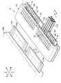
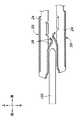
本実施形態の両面カードエッジコネクタは全体を符号10によって示されている。両面カードエッジコネクタ10は両面カードエッジ102のための電気接続用のコネクタである。両面カードエッジ102は、図1に示されているように、マイクロコンピュータ等の電気機器のアウターケース100から外部に突出しており、両面プリント基板の一部として、上面及び下面(不図示)の各々に、層状の基板側端子部104が左右方向に等ピッチをもって整列して複数形成されている。本実施形態では、基板側端子部104は両面カードエッジ102の上面及び下面の各々に24個ずつ形成されている。基板側端子部104は、後述する端子部材20のオフセット配置に応じて隣り合うもの同士で端子長が異なっている。なお、端子長が異なっていることは必須ではない。 The double-sided card edge connector of this embodiment is indicated by
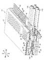
両面カードエッジコネクタ10は、図1〜図4に示されているように、樹脂成形品によるコネクタハウジング12を有する。コネクタハウジング12は、左右方向に長い扁平な形状をしており、前部に開口した差込口14Aから両面カードエッジ102を差し込まれる差込室14を含む。コネクタハウジング12には、図1〜図4に示されているように、差込室14の上側及び下側の各々に、差込室14を挟んで互いに対向する端子取付凹部16が左右方向に等ピッチをもって複数、本実施形態では24個形成されている。端子取付凹部16の各々に端子部材20が取り付けられている。 The double-sided
上下の端子部材20は、差込室14を挟んで互いに対向するもの同士で、端子対A或いはB(図5参照)をなしており、この端子対AとBとが交互に左右方向に等ピッチをもって複数、本実施形態では、合計で24個(24対)整列配置されている。これにより、上下の端子部材20は各々両面カードエッジ102の上面及び下面の各基板側端子部104に個別に対応する。 The upper and lower
端子部材20は、図7に示されているように、上下のもので互い上下に反転しているが、全て同一形状のプレス成形品(部品)によって構成されている。ここで云う同一形状のプレス成形品は、形状はもとより各部の寸法も同一のプレス成形品である。 As shown in FIG. 7, the
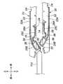
端子部材20は、前部に溝形横断面形状部22を有する端子本体24と、溝形横断面形状部22の底部22Aに連結された基端26Aを有する接点片26とを含み、端子本体24の後部に形成された芯線バレル28及び被覆部バレル30に各々被覆ケーブル110の芯線112及び被覆部114を圧着されている。 The
接点片26は、溝形横断面形状部22の底部22Aの前端から後方に折り返されて折返部を基端26Aとした基端側片部26Bと、基端側片部26Bの先端から前方に折り返された遊端側片部26Cとを有し、全体が底部22Aと一体の折曲片によって構成され、上下方向に弾性変形可能なばね性を有する。 The
基端側片部26Bと遊端側片部26Cとを接続する折返部には接触部32が形成されている。接触部32は、自由状態において差込室14内に位置し、差込室14に差し込まれる両面カードエッジ102の上面或いは下面と接触する。ここで云う自由状態とは、接点片26が外力によって弾性変形していない状態を云う。 A
遊端側片部26Cの先端は遊端になっており、当該遊端に基板側端子部104との導電接続部をなす接点部34が形成されている。接点部34は、自由状態において溝形横断面形状部22内に位置して差込室14から離れた位置にあり、差込室14に対する両面カードエッジ102の差し込みによって接触部32が両面カードエッジ102によって押圧されて接点片26が弾性変形によって差込室14に進入する位置に移動することにより、所定の端子接触圧をもって基板側端子部104に押し付けられる。 The tip of the free end
更に、接点片26は、接触部32と接点部34との間、つまり、遊端側片部26Cの中間部には溝形横断面形状部22の側部22Bに形成された凹部(支持部)36に揺動可能に係合する湾曲形状の枢支部38が形成されている。枢支部38が凹部36に係合することにより、遊端側片部26Cが枢支部38を中心として端子本体24に対して略上下方向に揺動可能に枢支される。 Further, the
溝形横断面形状部22の底部22Aには後述するコネクタハウジング12のランス片18が係合する被係止部をなす開口40が形成されていると共に、溝形横断面形状部22の後端には後向きの垂直面によるリテーナ当接部42が形成されている。 The
上述の端子部材20では、接点部34は、接触部32が両面カードエッジ102によって押圧されるまでは、両面カードエッジ102の上面或いは下面に摺接することがないから、接点部34が両面カードエッジ102との接触によって摩耗したり、破損したりすることが防止される。また、組付時にオイル等の不純物によって接点部34が汚染されることが回避される。これにより、接点部34に不純物が付着したことに起因する導通不良が生じることが防止され、接触部32と基板側端子部104との導通接続が高い信頼性をもって良好に行われることが保証される。 In the
また、枢支部38を支点、接触部32を力点、接点部34を作用点とする梃子が構成され、接触部32が押圧されると、梃子の動作の下に、接点部34が差込室14内に進入する側に移動する動作が再現性よく良好に行われる。 Further, a lever is configured in which the
端子部材20は、上下のものを含めて全て同一形状の部品であることから、開口40及びリテーナ当接部42は、全ての端子部材20において、端子部材20の長手方向(差込室14に対する両面カードエッジ102の差込方向と同じ方向=前後方向)の同一位置に形成されている。 Since the
端子取付凹部16に対する端子部材20の取り付けは、コネクタハウジング12の後側から端子本体24の先端24Aがコネクタハウジング12の前壁部12Aに突き当たる位置まで端子部材20を端子取付凹部16に沿って挿入することにより行われる。 To attach the
コネクタハウジング12には、コネクタハウジング12の後部上側及び後部下側の各々から端子取付凹部16毎に前方に延出した片持ち片によるばね性を有するランス片18及び19が複数一体成形されている。 A plurality of
ランス片18及び19は、端子部材20の係止部をなすものであり、端子本体24の先端24Aがコネクタハウジング12の前壁部12Aに突き当たる位置まで端子部材20が挿入されると、その遊端18A、19A側が端子部材20の開口40に係合することにより、端子部材20をコネクタハウジング12に係止し、端子部材20がコネクタハウジング12に対して後方に抜け出す方向に移動することを阻止し、コネクタハウジング12に対する端子部材20の前後方向(差込室14に対する両面カードエッジ102の差込方向)の位置決めを行う。 The
コネクタハウジング12の後部には、上下の端子部材20間に差し込まれる1枚の板状のリヤリテーナ50が固定されている。リヤリテーナ50は、樹脂成形品であり、上下両面に、各端子部材20のリテーナ当接部42に当接する垂直な前面を有する突起部52及び54が複数一体成形されている。
リヤリテーナ50は、突起部52あるいは54の前面が上下の端子部材20のリテーナ当接部42に当接することにより、端子部材20がコネクタハウジング12に対して後方に抜け出す方向に移動することを阻止し、ランス片18及び19と併せてコネクタハウジング12に対する端子部材20の前後方向(差込室14に対する両面カードエッジ102の差込方向)の位置決めを行う。A plate-shaped
The
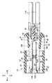
図2〜図4に示されているように、ランス片18と19とは差込室14に対する両面カードエッジ102の差込方向(前後方向)にオフセットして設けられていると共に、突起部52と54とが前後方向にオフセットして設けられている。 As shown in FIGS. 2 to 4, the
これにより、互いに上下に対する端子部材20は、端子対A或いはB毎に、差込室14に対する両面カードエッジ102の差込方向(前後方向)に所定のオフセット量S(図7参照)をもってオフセットされてコネクタハウジング12に固定される。このオフセットによって上側の端子部材20の接触部32と下側の端子部材20の接触部32とが前後方向に互いにオフセットされ、差込室14に対する接触部32の突出量が大きくても、上側の接触部32と下側の接触部32とが接触することがない。つまり、上下の接触部32が正対する場合により差込室14に対する接触部32の突出量を大きく設定することができる。 As a result, the
これにより、差込室14に両面カードエッジ102が差し込まれた際の接点片26の弾性変形量が大きくなり、それに伴い基板側端子部104に対する接点部34の端子接触圧が高くなる。 As a result, the amount of elastic deformation of the
このようなオフセット仕様でも、互いに対向する全ての端子部材20が同一形状の部品によって構成されるので、オフセット配置のために、端子部材20を含む必要な部品の種類が増加することがなく、部品管理が面倒なものになることがない。また、上下の端子部材20は同一の部品であるから、上下の端子部材20をコネクタハウジング12に誤組み付けする虞がない。 Even with such an offset specification, since all the
端子対Aでは、下側の端子部材20が上側の端子部材20より前側にオフセットされ、端子対Bでは、下側の端子部材20が上側の端子部材20より後側にオフセットされており、端子対Aと端子対Bとが、互いに同数(12個)だけ、一つずつ交互に配置(千鳥配置)されている。なお、図6は下側の端子部材20の配列位置を示している。 In terminal pair A, the
これにより、端子対A及びBにおいて上下の接触部32が互いに前後方向にオフセットされていることにより、両面カードエッジ102の上下面が上下の接触部32に接触した際に、両面カードエッジ102に作用する左右方向の水平軸線周りに回転モーメントが相殺され、差込室14に両面カードエッジ102が差し込まれた際に、両面カードエッジ102が上下に傾くことなく水平に差し込むことができる。 As a result, the upper and
端子対Aと端子対Bとの合計が偶数で、端子対Aと端子対Bとは互いに同数であれば、必ずしも千鳥配置である必要はなく、図8及び図9に示されているように、端子対Aと端子対Bとが複数の群をなして配置されていてもよい。 If the total of terminal-to-A and terminal-to-B is even, and the number of terminal-to-A and terminal-to-B is the same, the staggered arrangement is not always necessary, as shown in FIGS. 8 and 9. , Terminal-to-A and terminal-to-B may be arranged in a plurality of groups.
オフセットにより、端子対Aあるいは端子対Bにおける上下の端子部材20の接点片26が、図10に示されているように、差込方向に直交する投影面で見て互いに重なる部分を含んでいてもよい。この場合には、上側の接触部32と下側の接触部32とが接触することがなく、差込室14に対する接触部32の突出量をより一層大きく設定することができる。この場合も端子対Aあるいは端子対Bにおける全ての端子部材20が同一形状の部品で構成することができる。 Due to the offset, the
これにより、差込室14に両面カードエッジ102が差し込まれた際の接点片26の弾性変形量がより一層大きくなり、それに伴い基板側端子部104に対する接点部34の端子接触圧より一層が高くなる。また、図11に示されているように、板厚が薄い両面カードエッジ102にも対応することができる。 As a result, the amount of elastic deformation of the
以上、本発明を、その好適な実施形態について説明したが、当業者であれば容易に理解できるように、本発明はこのような実施形態により限定されるものではなく、本発明の趣旨を逸脱しない範囲で適宜変更可能である。 The present invention has been described above with respect to preferred embodiments thereof, but as can be easily understood by those skilled in the art, the present invention is not limited to such embodiments and deviates from the gist of the present invention. It can be changed as appropriate as long as it does not.
端子部材20の接点片26の構造は、上述した実施形態のものに限られることはなく、図12に示されているように、端子本体24に対する接点片26の延在方向が前後逆のものであっても、枢支部38が省略されたものであってもよい。また、図13〜図16に示されている参考例は、単純な片持ち片による端子部材20の接点片26の構造である。また、上下の端子部材20による複数の端子対は、必ずしも千鳥配置等でなくてもよく、図17に示されているように、下側の端子部材20の全てが上側の端子部材20に対して一様に前側にオフセットされていてもよい。また、端子対の個数は偶数に限られることなく、奇数であってもよい。The structure of the
また、上記実施形態に示した構成要素は必ずしも全てが必須なものではなく、本発明の趣旨を逸脱しない限りにおいて適宜取捨選択することが可能である。 In addition, not all of the components shown in the above embodiments are indispensable, and they can be appropriately selected as long as they do not deviate from the gist of the present invention.
10 両面カードエッジコネクタ
12 コネクタハウジング
12A 前壁部
14 差込室
14A 差込口
16 端子取付凹部
18 ランス片(係止部)
18A 遊端
19 ランス片(係止部)
19A 遊端
20 端子部材
22 溝形横断面形状部
22A 底部
22B 側部
24 端子本体
24A 先端
26 接点片
26A 基端
26B 基端側片部
26C 遊端側片部
28 芯線バレル
30 被覆部バレル
32 接触部
34 接点部
36 凹部(支持部)
38 枢支部
40 開口(被係止部)
42 リテーナ当接部
50 リヤリテーナ
52 突起部
100 アウターケース
102 両面カードエッジ
104 基板側端子部
110 被覆ケーブル
112 芯線
114 被覆部
A 端子対
B 端子対10 Double-sided
18A Free end 19 Lance piece (locking part)
19A Free end 20
38
42
Claims (8)
Translated fromJapaneseばね性を有する接点片を含み、前記コネクタハウジングに取り付けられた少なくとも2個の端子部材とを有し、
前記端子部材は前記接点片が前記差込室の両側にあって互いに対向するように配置され、
前記接点片は、前記差込室にあって前記両面カードエッジと接触する接触部を含むとともに、
互いに対向する前記端子部材が同一形状の部品によって構成され、互いに対向する前記端子部材が前記差込室に対する前記両面カードエッジの差込方向にオフセットして前記コネクタハウジングに固定されている両面カードエッジコネクタであって、
前記端子部材は溝形横断面形状部を有する端子本体を含み、
前記接点片は、端子本体に連結された基端と、自由状態において前記溝形横断面形状部内に位置して前記差込室から離れた位置に位置する遊端とを含み、前記基端と前記遊端との間に自由状態において前記差込室内に位置する前記接触部を有し、前記遊端は前記両面カードエッジに設けられている基板側端子との接点部をなしており、当該接点部は、前記差込室に対する前記両面カードエッジの差し込みによって前記接触部が前記両面カードエッジによって押圧されることにより前記差込室に進入する位置に変位し、前記基板側端子に押し付けられる両面カードエッジコネクタ。A connector housing that includes an insertion chamber into which a double-sided card edge can be inserted,
It comprises a springy contact piece and has at least two terminal members attached to the connector housing.
The terminal members are arranged so that the contact pieces are on both sides of the insertion chamber and face each other.
The contact piece,with includes a contact portion that contacts the both sides card edge be in the insertion chamber,
The terminal members facing each other are composed of parts having the same shape, and the terminal members facing each other are offset in the insertion direction of the double-sided card edge with respect to the insertion chamber and fixed to the connector housing. It ’s a connector,
The terminal member includes a terminal body having a groove-shaped cross-sectional shape portion.
The contact piece includes a base end connected to a terminal body and a free end located in the groove-shaped cross-sectional shape portion in a free state and located away from the insertion chamber, and includes the base end. The free end has the contact portion located in the insertion chamber in a free state, and the free end forms a contact portion with a substrate side terminal provided on the double-sided card edge. The contact portion is displaced to a position where it enters the insertion chamber by inserting the double-sided card edge into the insertion chamber, and the contact portion is pressed by the double-sided card edge, and is pressed against the substrate side terminal. Card edge connector.
互いに対向する前記端子部材のための前記係止部は前記両面カードエッジの差込方向にオフセットして設けられている請求項1に記載の両面カードエッジコネクタ。The terminal members facing each other have a locked portion that is locked to the connector housing, and the connector housing engages the locked portion of the terminal member to lock the terminal member. Has a stop,
The double-sided card edge connector according to claim 1, wherein the locking portions for the terminal members facing each other are provided so as to be offset in the insertion direction of the double-sided card edge.
Priority Applications (4)
| Application Number | Priority Date | Filing Date | Title |
|---|---|---|---|
| JP2016149459AJP6778042B2 (en) | 2016-07-29 | 2016-07-29 | Double-sided card edge connector |
| DE102017115654.2ADE102017115654B4 (en) | 2016-07-29 | 2017-07-12 | Board connector for board equipped on both sides |
| CN201710594784.9ACN107666046B (en) | 2016-07-29 | 2017-07-20 | Double-side card edge connector |
| US15/662,900US10164363B2 (en) | 2016-07-29 | 2017-07-28 | Double-sided card edge connector |
Applications Claiming Priority (1)
| Application Number | Priority Date | Filing Date | Title |
|---|---|---|---|
| JP2016149459AJP6778042B2 (en) | 2016-07-29 | 2016-07-29 | Double-sided card edge connector |
Publications (2)
| Publication Number | Publication Date |
|---|---|
| JP2018018749A JP2018018749A (en) | 2018-02-01 |
| JP6778042B2true JP6778042B2 (en) | 2020-10-28 |
Family
ID=60951552
Family Applications (1)
| Application Number | Title | Priority Date | Filing Date |
|---|---|---|---|
| JP2016149459AActiveJP6778042B2 (en) | 2016-07-29 | 2016-07-29 | Double-sided card edge connector |
Country Status (4)
| Country | Link |
|---|---|
| US (1) | US10164363B2 (en) |
| JP (1) | JP6778042B2 (en) |
| CN (1) | CN107666046B (en) |
| DE (1) | DE102017115654B4 (en) |
Families Citing this family (5)
| Publication number | Priority date | Publication date | Assignee | Title |
|---|---|---|---|---|
| CN207459324U (en)* | 2017-11-30 | 2018-06-05 | 安费诺商用电子产品(成都)有限公司 | High speed card connector |
| WO2022039055A1 (en) | 2020-08-21 | 2022-02-24 | 日本端子株式会社 | Connector |
| JP7476734B2 (en)* | 2020-09-07 | 2024-05-01 | 株式会社オートネットワーク技術研究所 | Card Edge Connectors |
| JP7684845B2 (en)* | 2021-06-17 | 2025-05-28 | 日本端子株式会社 | Connector Terminals |
| DE102022103851A1 (en) | 2022-02-18 | 2023-08-24 | Weidmüller Interface GmbH & Co. KG | Connection device and connection unit |
Family Cites Families (14)
| Publication number | Priority date | Publication date | Assignee | Title |
|---|---|---|---|---|
| US3399377A (en)* | 1966-12-05 | 1968-08-27 | Schjeldahl Co G T | Electrical connector with contact receiving channels |
| US3646504A (en)* | 1969-10-17 | 1972-02-29 | Litton Systems Inc | Electrical connector |
| JPS5075088U (en)* | 1973-11-14 | 1975-07-01 | ||
| US4343523A (en) | 1980-05-27 | 1982-08-10 | Ford Motor Company | Printed circuit board edge connector |
| US4993972A (en) | 1990-02-07 | 1991-02-19 | Lin Yu C | Multi-purpose PC board connector |
| US5785556A (en) | 1996-07-16 | 1998-07-28 | Molex Incorporated | Edge connector for a printed circuit board |
| CN2368174Y (en)* | 1999-03-12 | 2000-03-08 | 富士康(昆山)电脑接插件有限公司 | Clamping-fringe connector |
| JP2001185300A (en)* | 1999-12-24 | 2001-07-06 | Auto Network Gijutsu Kenkyusho:Kk | connector |
| JP2002093502A (en)* | 2000-09-14 | 2002-03-29 | Fujitsu Ten Ltd | Floating connector |
| JP2007287380A (en)* | 2006-04-13 | 2007-11-01 | Fujikura Ltd | Double-sided FPC / FFC connector |
| TWI321873B (en)* | 2006-07-10 | 2010-03-11 | Fci Connectors Singapore Pte | High speed connector |
| CN201498675U (en)* | 2009-08-26 | 2010-06-02 | 富士康(昆山)电脑接插件有限公司 | card edge connector |
| JP2010116663A (en) | 2009-12-21 | 2010-05-27 | Toyobo Co Ltd | Method for producing molded body from polyphosphoric acid solution |
| CN202855978U (en)* | 2012-10-29 | 2013-04-03 | 龙杰(苏州)精密工业有限公司 | Terminal structure used for reducing insertion force of connector |
- 2016
- 2016-07-29JPJP2016149459Apatent/JP6778042B2/enactiveActive
- 2017
- 2017-07-12DEDE102017115654.2Apatent/DE102017115654B4/enactiveActive
- 2017-07-20CNCN201710594784.9Apatent/CN107666046B/enactiveActive
- 2017-07-28USUS15/662,900patent/US10164363B2/enactiveActive
Also Published As
| Publication number | Publication date |
|---|---|
| DE102017115654B4 (en) | 2023-12-07 |
| US20180034177A1 (en) | 2018-02-01 |
| DE102017115654A1 (en) | 2018-02-01 |
| JP2018018749A (en) | 2018-02-01 |
| US10164363B2 (en) | 2018-12-25 |
| CN107666046B (en) | 2020-11-10 |
| CN107666046A (en) | 2018-02-06 |
Similar Documents
| Publication | Publication Date | Title |
|---|---|---|
| JP6778042B2 (en) | Double-sided card edge connector | |
| JP4954253B2 (en) | Board to board connector | |
| US9397423B2 (en) | Board-to-board connector | |
| US7238032B2 (en) | Connector arrangement between a flat flex cable and a component | |
| CN109004411B (en) | Multi-contact connector | |
| US9735486B1 (en) | Electrical connector | |
| JP2022507405A (en) | Receptacle connector | |
| KR101860641B1 (en) | Connector | |
| US7210965B1 (en) | Cable connector assembly | |
| TW200922029A (en) | Connector having connection detecting means which is elastically deformable | |
| JP2008539557A (en) | Connector assembly | |
| US10707619B2 (en) | Movable connector | |
| CN104253337A (en) | Connector, and header and socket included in the same | |
| CN111684666B (en) | Connector | |
| US9065200B2 (en) | Connector, and assembly of cable and connector | |
| JP2013178892A (en) | Cable connector | |
| CN115377719A (en) | Terminal, wire connector and wire-to-board connector | |
| US10622763B2 (en) | Connector | |
| KR100885062B1 (en) | Electrical connector for printer ink cartridge | |
| JP6831428B2 (en) | Terminals and connectors | |
| JP4795461B2 (en) | connector | |
| JP5931343B2 (en) | Connector device | |
| CN114600321B (en) | Connector | |
| CN105846229A (en) | Connector assembly and connector | |
| JP4644228B2 (en) | connector |
Legal Events
| Date | Code | Title | Description |
|---|---|---|---|
| A621 | Written request for application examination | Free format text:JAPANESE INTERMEDIATE CODE: A621 Effective date:20190213 | |
| A977 | Report on retrieval | Free format text:JAPANESE INTERMEDIATE CODE: A971007 Effective date:20191007 | |
| A131 | Notification of reasons for refusal | Free format text:JAPANESE INTERMEDIATE CODE: A131 Effective date:20191023 | |
| A601 | Written request for extension of time | Free format text:JAPANESE INTERMEDIATE CODE: A601 Effective date:20191220 | |
| A521 | Request for written amendment filed | Free format text:JAPANESE INTERMEDIATE CODE: A523 Effective date:20200114 | |
| A02 | Decision of refusal | Free format text:JAPANESE INTERMEDIATE CODE: A02 Effective date:20200520 | |
| A521 | Request for written amendment filed | Free format text:JAPANESE INTERMEDIATE CODE: A523 Effective date:20200728 | |
| C60 | Trial request (containing other claim documents, opposition documents) | Free format text:JAPANESE INTERMEDIATE CODE: C60 Effective date:20200728 | |
| A521 | Request for written amendment filed | Free format text:JAPANESE INTERMEDIATE CODE: A821 Effective date:20200728 | |
| A911 | Transfer to examiner for re-examination before appeal (zenchi) | Free format text:JAPANESE INTERMEDIATE CODE: A911 Effective date:20200825 | |
| C21 | Notice of transfer of a case for reconsideration by examiners before appeal proceedings | Free format text:JAPANESE INTERMEDIATE CODE: C21 Effective date:20200901 | |
| TRDD | Decision of grant or rejection written | ||
| A01 | Written decision to grant a patent or to grant a registration (utility model) | Free format text:JAPANESE INTERMEDIATE CODE: A01 Effective date:20200915 | |
| A61 | First payment of annual fees (during grant procedure) | Free format text:JAPANESE INTERMEDIATE CODE: A61 Effective date:20201009 | |
| R150 | Certificate of patent or registration of utility model | Ref document number:6778042 Country of ref document:JP Free format text:JAPANESE INTERMEDIATE CODE: R150 | |
| R250 | Receipt of annual fees | Free format text:JAPANESE INTERMEDIATE CODE: R250 | |
| R250 | Receipt of annual fees | Free format text:JAPANESE INTERMEDIATE CODE: R250 | |
| R250 | Receipt of annual fees | Free format text:JAPANESE INTERMEDIATE CODE: R250 |