JP6777694B2 - Endoscope adapter - Google Patents
Endoscope adapterDownload PDFInfo
- Publication number
- JP6777694B2 JP6777694B2JP2018159329AJP2018159329AJP6777694B2JP 6777694 B2JP6777694 B2JP 6777694B2JP 2018159329 AJP2018159329 AJP 2018159329AJP 2018159329 AJP2018159329 AJP 2018159329AJP 6777694 B2JP6777694 B2JP 6777694B2
- Authority
- JP
- Japan
- Prior art keywords
- endoscope
- adapter
- holding
- robot arm
- holding member
- Prior art date
- Legal status (The legal status is an assumption and is not a legal conclusion. Google has not performed a legal analysis and makes no representation as to the accuracy of the status listed.)
- Active
Links
Images


Classifications
- A—HUMAN NECESSITIES
- A61—MEDICAL OR VETERINARY SCIENCE; HYGIENE
- A61B—DIAGNOSIS; SURGERY; IDENTIFICATION
- A61B1/00—Instruments for performing medical examinations of the interior of cavities or tubes of the body by visual or photographical inspection, e.g. endoscopes; Illuminating arrangements therefor
- A61B1/00112—Connection or coupling means
- A61B1/00121—Connectors, fasteners and adapters, e.g. on the endoscope handle
- A—HUMAN NECESSITIES
- A61—MEDICAL OR VETERINARY SCIENCE; HYGIENE
- A61B—DIAGNOSIS; SURGERY; IDENTIFICATION
- A61B1/00—Instruments for performing medical examinations of the interior of cavities or tubes of the body by visual or photographical inspection, e.g. endoscopes; Illuminating arrangements therefor
- A61B1/00002—Operational features of endoscopes
- A61B1/00043—Operational features of endoscopes provided with output arrangements
- A61B1/00045—Display arrangement
- A—HUMAN NECESSITIES
- A61—MEDICAL OR VETERINARY SCIENCE; HYGIENE
- A61B—DIAGNOSIS; SURGERY; IDENTIFICATION
- A61B1/00—Instruments for performing medical examinations of the interior of cavities or tubes of the body by visual or photographical inspection, e.g. endoscopes; Illuminating arrangements therefor
- A61B1/00112—Connection or coupling means
- A61B1/00121—Connectors, fasteners and adapters, e.g. on the endoscope handle
- A61B1/00128—Connectors, fasteners and adapters, e.g. on the endoscope handle mechanical, e.g. for tubes or pipes
- A—HUMAN NECESSITIES
- A61—MEDICAL OR VETERINARY SCIENCE; HYGIENE
- A61B—DIAGNOSIS; SURGERY; IDENTIFICATION
- A61B1/00—Instruments for performing medical examinations of the interior of cavities or tubes of the body by visual or photographical inspection, e.g. endoscopes; Illuminating arrangements therefor
- A61B1/00131—Accessories for endoscopes
- A61B1/00133—Drive units for endoscopic tools inserted through or with the endoscope
- A—HUMAN NECESSITIES
- A61—MEDICAL OR VETERINARY SCIENCE; HYGIENE
- A61B—DIAGNOSIS; SURGERY; IDENTIFICATION
- A61B1/00—Instruments for performing medical examinations of the interior of cavities or tubes of the body by visual or photographical inspection, e.g. endoscopes; Illuminating arrangements therefor
- A61B1/00142—Instruments for performing medical examinations of the interior of cavities or tubes of the body by visual or photographical inspection, e.g. endoscopes; Illuminating arrangements therefor with means for preventing contamination, e.g. by using a sanitary sheath
- A—HUMAN NECESSITIES
- A61—MEDICAL OR VETERINARY SCIENCE; HYGIENE
- A61B—DIAGNOSIS; SURGERY; IDENTIFICATION
- A61B1/00—Instruments for performing medical examinations of the interior of cavities or tubes of the body by visual or photographical inspection, e.g. endoscopes; Illuminating arrangements therefor
- A61B1/00147—Holding or positioning arrangements
- A61B1/00149—Holding or positioning arrangements using articulated arms
- A—HUMAN NECESSITIES
- A61—MEDICAL OR VETERINARY SCIENCE; HYGIENE
- A61B—DIAGNOSIS; SURGERY; IDENTIFICATION
- A61B1/00—Instruments for performing medical examinations of the interior of cavities or tubes of the body by visual or photographical inspection, e.g. endoscopes; Illuminating arrangements therefor
- A61B1/00147—Holding or positioning arrangements
- A61B1/0016—Holding or positioning arrangements using motor drive units
- A—HUMAN NECESSITIES
- A61—MEDICAL OR VETERINARY SCIENCE; HYGIENE
- A61B—DIAGNOSIS; SURGERY; IDENTIFICATION
- A61B17/00—Surgical instruments, devices or methods
- A61B17/28—Surgical forceps
- A61B17/29—Forceps for use in minimally invasive surgery
- A61B17/2909—Handles
- A—HUMAN NECESSITIES
- A61—MEDICAL OR VETERINARY SCIENCE; HYGIENE
- A61B—DIAGNOSIS; SURGERY; IDENTIFICATION
- A61B18/00—Surgical instruments, devices or methods for transferring non-mechanical forms of energy to or from the body
- A61B18/04—Surgical instruments, devices or methods for transferring non-mechanical forms of energy to or from the body by heating
- A61B18/12—Surgical instruments, devices or methods for transferring non-mechanical forms of energy to or from the body by heating by passing a current through the tissue to be heated, e.g. high-frequency current
- A61B18/14—Probes or electrodes therefor
- A61B18/148—Probes or electrodes therefor having a short, rigid shaft for accessing the inner body transcutaneously, e.g. for neurosurgery or arthroscopy
- A—HUMAN NECESSITIES
- A61—MEDICAL OR VETERINARY SCIENCE; HYGIENE
- A61B—DIAGNOSIS; SURGERY; IDENTIFICATION
- A61B34/00—Computer-aided surgery; Manipulators or robots specially adapted for use in surgery
- A61B34/30—Surgical robots
- A—HUMAN NECESSITIES
- A61—MEDICAL OR VETERINARY SCIENCE; HYGIENE
- A61B—DIAGNOSIS; SURGERY; IDENTIFICATION
- A61B34/00—Computer-aided surgery; Manipulators or robots specially adapted for use in surgery
- A61B34/30—Surgical robots
- A61B34/37—Leader-follower robots
- A—HUMAN NECESSITIES
- A61—MEDICAL OR VETERINARY SCIENCE; HYGIENE
- A61B—DIAGNOSIS; SURGERY; IDENTIFICATION
- A61B46/00—Surgical drapes
- A61B46/10—Surgical drapes specially adapted for instruments, e.g. microscopes
- A—HUMAN NECESSITIES
- A61—MEDICAL OR VETERINARY SCIENCE; HYGIENE
- A61B—DIAGNOSIS; SURGERY; IDENTIFICATION
- A61B1/00—Instruments for performing medical examinations of the interior of cavities or tubes of the body by visual or photographical inspection, e.g. endoscopes; Illuminating arrangements therefor
- A61B1/00142—Instruments for performing medical examinations of the interior of cavities or tubes of the body by visual or photographical inspection, e.g. endoscopes; Illuminating arrangements therefor with means for preventing contamination, e.g. by using a sanitary sheath
- A61B1/00144—Hygienic packaging
- A—HUMAN NECESSITIES
- A61—MEDICAL OR VETERINARY SCIENCE; HYGIENE
- A61B—DIAGNOSIS; SURGERY; IDENTIFICATION
- A61B17/00—Surgical instruments, devices or methods
- A61B2017/00477—Coupling
- A—HUMAN NECESSITIES
- A61—MEDICAL OR VETERINARY SCIENCE; HYGIENE
- A61B—DIAGNOSIS; SURGERY; IDENTIFICATION
- A61B18/00—Surgical instruments, devices or methods for transferring non-mechanical forms of energy to or from the body
- A61B2018/00571—Surgical instruments, devices or methods for transferring non-mechanical forms of energy to or from the body for achieving a particular surgical effect
- A61B2018/00589—Coagulation
- A—HUMAN NECESSITIES
- A61—MEDICAL OR VETERINARY SCIENCE; HYGIENE
- A61B—DIAGNOSIS; SURGERY; IDENTIFICATION
- A61B34/00—Computer-aided surgery; Manipulators or robots specially adapted for use in surgery
- A61B34/30—Surgical robots
- A61B2034/301—Surgical robots for introducing or steering flexible instruments inserted into the body, e.g. catheters or endoscopes
- A—HUMAN NECESSITIES
- A61—MEDICAL OR VETERINARY SCIENCE; HYGIENE
- A61B—DIAGNOSIS; SURGERY; IDENTIFICATION
- A61B34/00—Computer-aided surgery; Manipulators or robots specially adapted for use in surgery
- A61B34/30—Surgical robots
- A61B2034/305—Details of wrist mechanisms at distal ends of robotic arms
Landscapes
- Health & Medical Sciences (AREA)
- Life Sciences & Earth Sciences (AREA)
- Surgery (AREA)
- Engineering & Computer Science (AREA)
- Animal Behavior & Ethology (AREA)
- Veterinary Medicine (AREA)
- Medical Informatics (AREA)
- Molecular Biology (AREA)
- Biomedical Technology (AREA)
- General Health & Medical Sciences (AREA)
- Public Health (AREA)
- Heart & Thoracic Surgery (AREA)
- Nuclear Medicine, Radiotherapy & Molecular Imaging (AREA)
- Physics & Mathematics (AREA)
- Radiology & Medical Imaging (AREA)
- Pathology (AREA)
- Optics & Photonics (AREA)
- Biophysics (AREA)
- Robotics (AREA)
- Otolaryngology (AREA)
- Plasma & Fusion (AREA)
- Neurosurgery (AREA)
- Neurology (AREA)
- Mechanical Engineering (AREA)
- Ophthalmology & Optometry (AREA)
- Endoscopes (AREA)
- Manipulator (AREA)
Description
Translated fromJapaneseこの発明は、内視鏡アダプタに関し、特に、内視鏡を保持する内視鏡アダプタに関する。 The present invention relates to an endoscope adapter, and more particularly to an endoscope adapter that holds an endoscope.
従来、内視鏡を保持する内視鏡保持装置が知られている(たとえば、特許文献1参照)。 Conventionally, an endoscope holding device for holding an endoscope is known (see, for example, Patent Document 1).
上記特許文献1には、内視鏡のホルダ部を吸着して保持する永久磁石を含むマウント部と、マウント部に収容され、内視鏡のホルダ部に設けられたギアに噛合するギア部とを備える内視鏡保持装置が開示されている。この特許文献1の内視鏡保持装置では、マウント部の永久磁石に内視鏡のホルダ部が吸着されると、マウント部のギア部と、内視鏡のギアとが噛合して、ギア部の駆動により内視鏡が回転するように構成されている。 In Patent Document 1, a mount portion including a permanent magnet that attracts and holds the holder portion of the endoscope, and a gear portion that is housed in the mount portion and meshes with a gear provided in the holder portion of the endoscope. An endoscope holding device comprising the above is disclosed. In the endoscope holding device of Patent Document 1, when the holder portion of the endoscope is attracted to the permanent magnet of the mount portion, the gear portion of the mount portion and the gear of the endoscope mesh with each other to form the gear portion. The endoscope is configured to rotate when driven by.
しかしながら、特許文献1の内視鏡保持装置では、マウント部の永久磁石に内視鏡のホルダ部が吸着されると、マウント部のギア部と、内視鏡のギアとが噛合して、ギア部の駆動により内視鏡が回転するように構成されている。このため、マウント部と内視鏡との間に清潔操作のためのドレープを挟むと、マウント部のギア部と内視鏡のギアとが噛合しなくなるため、内視鏡を回転させることができないという不都合がある。このため、内視鏡を保持する装置にドレープをかけた状態で内視鏡を回転可能に保持することが困難であるという問題点がある。 However, in the endoscope holding device of Patent Document 1, when the holder portion of the endoscope is attracted to the permanent magnet of the mount portion, the gear portion of the mount portion and the gear of the endoscope mesh with each other to form a gear. The endoscope is configured to rotate by driving the unit. For this reason, if a drape for clean operation is sandwiched between the mount and the endoscope, the gear of the mount and the gear of the endoscope will not mesh with each other, and the endoscope cannot be rotated. There is an inconvenience. Therefore, there is a problem that it is difficult to rotatably hold the endoscope in a state where the device for holding the endoscope is draped.
この発明は、内視鏡を保持するロボットアームにドレープをかけた状態で内視鏡を回転可能に保持することが可能な内視鏡アダプタを提供することである。 The present invention is to provide an endoscope adapter capable of rotatably holding an endoscope in a state where a robot arm holding the endoscope is draped.
この発明の一の局面による内視鏡アダプタは、ロボット手術システムのロボットアームにドレープアダプタを介して接続される内視鏡アダプタであって、ドレープアダプタに取り外し可能に接続するための基部と、基部に回転可能に設けられ、ドレープアダプタを介してロボットアームの回転駆動部によって回転駆動される被駆動部材と、先端に撮像部が設けられた挿入部と挿入部に接続された本体部とを含む内視鏡を、挿入部が延びる方向の回転軸線を中心に回転可能に保持する保持部と、内視鏡を保持した保持部に被駆動部材の回転を伝達する伝達機構と、を備え、保持部は、内視鏡を保持する第1保持部材と、基部に設けられ、内視鏡を保持した第1保持部材を回転可能に保持する第2保持部材とを含む。The endoscope adapter according to one aspect of the present invention is an endoscope adapter that is connected to the robot arm of a robotic surgery system via a drape adapter, and has a base and a base for detachably connecting to the drape adapter. Includes a driven member that is rotatably provided and is rotationally driven by a rotary drive unit of the robot arm via a drape adapter, an insertion portion provided with an imaging unit at the tip, and a main body portion connected to the insertion portion. the endoscope includes a holding portion that rotatably holds the center of the axis of rotation of the insertion portion extends, and a transmission mechanism for transmitting the rotation of the driven member in the holding portion which holds the endoscope, theholding The unit includes a first holding member that holds the endoscope and a second holding member that is provided at the base and rotatably holds the first holding member that holds the endoscope .
この発明の一の局面による内視鏡アダプタでは、上記のように構成することによって、ロボットアームとドレープアダプタとの間にドレープを挟み込んだ状態で、ロボットアームの回転駆動部の回転駆動をドレープアダプタを介して内視鏡を保持した保持部に伝達することができるので、内視鏡を挿入部が延びる方向の回転軸線を中心に回転させることができる。これにより、内視鏡を保持するロボットアームにドレープをかけた状態で内視鏡を回転可能に保持することができる。また、内視鏡の回転以外の移動は、ロボットアームの移動により行うことができるので、内視鏡の移動の自由度を向上させることができる。また、ロボットアームに取り付けるための専用の内視鏡を用いなくても、内視鏡アダプタに既存の内視鏡を取り付けて用いることができるので、汎用性を向上させることができる。 In the endoscope adapter according to one aspect of the present invention, the drape adapter is configured as described above to drive the rotation of the rotation drive unit of the robot arm with the drape sandwiched between the robot arm and the drape adapter. Since the endoscope can be transmitted to the holding portion holding the endoscope via the above, the endoscope can be rotated about the rotation axis in the direction in which the insertion portion extends. As a result, the endoscope can be rotatably held in a state where the robot arm holding the endoscope is draped. Further, since the movement other than the rotation of the endoscope can be performed by the movement of the robot arm, the degree of freedom of movement of the endoscope can be improved. Further, since the existing endoscope can be attached to the endoscope adapter without using a dedicated endoscope for attaching to the robot arm, versatility can be improved.
本発明によれば、ロボット手術システムのロボットアームにアダプタを介して取り外し可能に接続される手術器具において、アダプタに対して手術器具を容易に着脱することができ、かつ、アダプタに安定して手術器具を固定することができる。 According to the present invention, in a surgical instrument that is detachably connected to a robot arm of a robotic surgery system via an adapter, the surgical instrument can be easily attached to and detached from the adapter, and surgery is stably performed on the adapter. The instrument can be fixed.
以下、実施形態を図面に基づいて説明する。 Hereinafter, embodiments will be described with reference to the drawings.
(ロボット手術システムの構成)
図1および図2を参照して、一実施形態によるロボット手術システム100の構成について説明する。(Structure of robotic surgery system)
The configuration of the
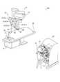
図1に示すように、ロボット手術システム100は、遠隔操作装置10と、患者側装置20と、を備えている。遠隔操作装置10は、患者側装置20に設けられた医療器具(medical equipment)を遠隔操作するために設けられている。患者側装置20によって実行されるべき動作態様指令が術者(surgeon)である操作者Oにより遠隔操作装置10に入力されると、遠隔操作装置10は、動作態様指令をコントローラ26を介して患者側装置20に送信する。そして、患者側装置20は、遠隔操作装置10から送信された動作態様指令に応答して、ロボットアーム21に取り付けられた手術器具(surgical instrument)40、内視鏡50等の医療器具を操作する。これにより、低侵襲手術が行われる。 As shown in FIG. 1, the
患者側装置20は、患者Pに対して手術を行うインターフェースを構成する。患者側装置20は、患者Pが横たわる手術台30の傍らに配置される。患者側装置20は、複数のロボットアーム21を有し、このうち1つのロボットアーム21(21b)に内視鏡50が取り付けられ、その他のロボットアーム21(21a)に手術器具40が取り付けられる。各ロボットアーム21は、プラットホーム23に共通に支持されている。複数のロボットアーム21は複数の関節を有し、それぞれの関節には、サーボモータを含む駆動部と、エンコーダ等の位置検出器とが設けられている。ロボットアーム21は、コントローラ26を介して与えられた駆動信号によりロボットアーム21に取り付けられた医療器具が所望の動作を行うように制御されるように構成されている。 The patient-
プラットホーム23は、手術室の床の上に載置されたポジショナ22に支持されている。ポジショナ22は、鉛直方向に調整可能な昇降軸を有する柱部24が、車輪を備え床面を移動可能なベース25に連結されている。 The
ロボットアーム21aには、先端部に医療器具としての手術器具40が着脱可能に取り付けられる。手術器具40は、ロボットアーム21aに取り付けられるハウジング43(図3参照)と、細長形状のシャフト42(図3参照)と、シャフト42の先端部に設けられたエンドエフェクタ41(図3参照)とを備えている。エンドエフェクタ41として、例えば、把持鉗子、シザーズ、フック、高周波ナイフ、スネアワイヤ、クランプ、ステイプラーが挙げられるがこれに限られるものではなく、各種の処置具を適用することができる。患者側装置20を用いた手術において、ロボットアーム21aは、患者Pの体表に留置したカニューラ(トロッカ)を介して患者Pの体内に手術器具40を導入する。そして、手術器具40のエンドエフェクタ41は、手術部位の近傍に配置される。 A
ロボットアーム21bには、先端部に医療器具としての内視鏡50が着脱可能に取り付けられる。内視鏡50は、患者Pの体腔内を撮影するものであり、撮影した画像は、遠隔操作装置10に対して出力される。内視鏡50として、3次元画像を撮影することができる3D内視鏡若しくは2D内視鏡が用いられる。患者側装置20を用いた手術において、ロボットアーム21bは、患者Pに体表に留置したトロッカを介して患者Pの体内に内視鏡50を導入する。そして、内視鏡50が手術部位の近傍に配置される。 An
遠隔操作装置10は、操作者Oとのインターフェースを構成する。遠隔操作装置10は、ロボットアーム21に取り付けられた医療器具を操作者Oが操作するための装置である。すなわち、遠隔操作装置10は、操作者Oによって入力された手術器具40および内視鏡50によって実行されるべき動作態様指令をコントローラ26を介して患者側装置20へ送信可能に構成されている。遠隔操作装置10は、たとえば、マスタの操作をしながらも患者Pの様子がよく見えるように手術台30の傍らに設置される。なお、遠隔操作装置10は、例えば動作態様指令を無線で送信するようにし、手術台30が設置された手術室とは別室に設置することも可能である。 The remote control device 10 constitutes an interface with the operator O. The remote control device 10 is a device for the operator O to operate the medical device attached to the
手術器具40によって実行されるべき動作態様とは、手術器具40の動作(一連の位置及び姿勢)及び手術器具40個別の機能によって実現される動作の態様である。たとえば、手術器具40が把持鉗子である場合には、手術器具40によって実行されるべき動作態様とは、エンドエフェクタ41の手首のロール回転位置及びピッチ回転位置と、ジョーの開閉を行う動作である。また、手術器具40が高周波ナイフである場合には、手術器具40によって実行されるべき動作態様とは、高周波ナイフの振動動作、具体的には高周波ナイフに対する電流の供給であり得る。また、手術器具40がスネアワイヤである場合には、手術器具40によって実行されるべき動作態様とは、束縛動作および束縛状態の解放動作であり得る。また、バイポーラやモノポーラに電流を供給することによって手術対象部位を焼き切る動作であり得る。 The motion mode to be performed by the
内視鏡50によって実行されるべき動作態様とは、たとえば、内視鏡50先端の位置及び姿勢、又はズーム倍率の設定である。 The operation mode to be executed by the
遠隔操作装置10は、図1および図2に示すように、操作ハンドル11と、操作ペダル部12と、表示部13と、制御装置14と、を備えている。 As shown in FIGS. 1 and 2, the remote control device 10 includes an
操作ハンドル11は、ロボットアーム21に取り付けられた医療器具を遠隔で操作するために設けられている。具体的には、操作ハンドル11は、医療器具(手術器具40、内視鏡50)を操作するための操作者Oによる操作を受け付ける。操作ハンドル11は、水平方向に沿って2つ設けられている。つまり、2つの操作ハンドル11のうち一方の操作ハンドル11は、操作者Oの右手により操作され、2つの操作ハンドル11のうち他方の操作ハンドル11は、操作者Oの左手により操作される。 The operation handle 11 is provided for remotely operating the medical device attached to the
また、操作ハンドル11は、遠隔操作装置10の後方側から、前方側に向かって延びるように配置されている。操作ハンドル11は、所定の3次元の操作領域内で動かすことができるように構成されている。すなわち、操作ハンドル11は、上下方向、左右方向、および前後方向に動かすことができるように構成されている。 Further, the operation handle 11 is arranged so as to extend from the rear side of the remote control device 10 toward the front side. The operation handle 11 is configured to be movable within a predetermined three-dimensional operation area. That is, the operation handle 11 is configured to be movable in the vertical direction, the horizontal direction, and the front-rear direction.
遠隔操作装置10と患者側装置20とは、ロボットアーム21aおよびロボットアーム21bの動作の制御においては、マスタスレーブ型のシステムを構成する。すなわち、操作ハンドル11は、マスタスレーブ型のシステムにおけるマスタ側の操作部を構成し、医療器具が取り付けられたロボットアーム21aおよびロボットアーム21bはスレーブ側の動作部を構成する。そして、操作ハンドル11を操作者Oが操作すると、操作ハンドル11の動きをロボットアーム21aの先端部(手術器具40のエンドエフェクタ41)またはロボットアーム21bの先端部(内視鏡50)がトレースして移動するようにロボットアーム21aまたはロボットアーム21bの動作が制御される。 The remote control device 10 and the
また、患者側装置20は、設定された動作倍率に応じてロボットアーム21aの動作を制御するよう構成されている。たとえば、動作倍率が1/2倍に設定されている場合、手術器具40のエンドエフェクタ41は、操作ハンドル11の移動距離の1/2の移動距離を移動するよう制御される。これによって、精細な手術を精確に行うことができる。 Further, the patient-
操作ペダル部12は、医療器具に関する機能を実行するための複数のペダルを含んでいる。複数のペダルは、凝固ペダルと、切断ペダルと、カメラペダルと、クラッチペダルと、を含んでいる。また、複数のペダルは、操作者Oの足により操作される。 The
凝固ペダルは、手術器具40を用いて手術部位を凝固させる操作を行うことができる。具体的には、凝固ペダルは、操作されることにより、手術器具40に凝固用の電圧が印加されて、手術部位の凝固が行われる。切断ペダルは、手術器具40を用いて手術部位を切断させる操作を行うことができる。具体的には、切断ペダルは、操作されることにより、手術器具40に切断用の電圧が印加されて、手術部位の切断が行われる。 The coagulation pedal can perform an operation of coagulating the surgical site using the
カメラペダルは、体腔内を撮像する内視鏡50の位置及び姿勢を操作するために用いられる。具体的には、カメラペダルは、内視鏡50の操作ハンドル11による操作を有効にする。つまり、カメラペダルが押されている間は、操作ハンドル11により内視鏡50の位置および姿勢を操作することが可能である。たとえば、内視鏡50は、左右の操作ハンドル11の両方を用いることにより操作される。具体的には、左右の操作ハンドル11の中間点を中心に左右の操作ハンドル11を回動させることにより、内視鏡50が回動される。また、左右の操作ハンドル11を共に押し込むことにより、内視鏡50が奥に進む。また、左右の操作ハンドル11を共に引っ張ることにより、内視鏡50が手前に戻る。また、左右の操作ハンドル11を共に上下左右に移動させることにより、内視鏡50が上下左右に移動する。 The camera pedal is used to control the position and posture of the
クラッチペダルは、ロボットアーム21と、操作ハンドル11との操作接続を一時切断し手術器具40の動作を停止させる場合に用いられる。具体的には、クラッチペダルが操作されている間は、操作ハンドル11を操作しても、患者側装置20のロボットアーム21が動作しない。たとえば、操作により操作ハンドル11が移動可能な範囲の端部近傍に来た場合に、クラッチペダルが操作されることにより、操作接続を一時切断して、操作ハンドル11を中央位置付近に戻すことができる。そして、クラッチペダルの操作を中止するとロボットアーム21と操作ハンドル11とが再び接続され、中央付近で操作ハンドル11の操作を再開することができる。 The clutch pedal is used when the operation connection between the
表示部13は、内視鏡50が撮像した画像を表示することができるものである。表示部13は、スコープ型表示部または非スコープ型表示部からなる。スコープ型表示部とは、たとえば、覗き込むタイプの表示部である。また、非スコープ型表示部とは、通常のパーソナルコンピュータのディスプレイのような覗き込むタイプではない平坦な画面を有する開放型の表示部を含む概念である。 The
スコープ型表示部が取り付けられた場合、患者側装置20のロボットアーム21bに取り付けられた内視鏡50により撮像された3D画像が表示される。非スコープ型表示部が取り付けられた場合にも、患者側装置20に設けられた内視鏡50により撮像された3D画像が表示される。なお、非スコープ型表示部が取り付けられた場合、患者側装置20に設けられた内視鏡50により撮像された2D画像が表示されてもよい。 When the scope type display unit is attached, the 3D image captured by the
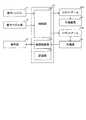
図2に示すように、制御装置14は、例えば、CPU等の演算器を有する制御部141と、ROMおよびRAM等のメモリを有する記憶部142と、画像制御部143とを含んでいる。制御装置14は、集中制御する単独の制御装置により構成されていてもよく、互いに協働して分散制御する複数の制御装置により構成されてもよい。制御部141は、操作ハンドル11により入力された動作態様指令を、操作ペダル部12の切替状態に応じて、ロボットアーム21aによって実行されるべき動作態様指令であるか、または、内視鏡50によって実行されるべき動作態様指令であるかを判定する。そして、制御部141は、操作ハンドル11に入力された動作態様指令が手術器具40によって実行されるべき動作態様指令であると判断すると、動作態様指令をロボットアーム21aに対して送信する。これによって、ロボットアーム21aが駆動され、この駆動によってロボットアーム21aに取り付けられた手術器具40の動作が制御される。 As shown in FIG. 2, the
また、制御部141は、操作ハンドル11に入力された動作態様指令が内視鏡50によって実行されるべき動作態様指令であると判定すると、当該動作態様指令をロボットアーム21bに対して送信する。これによって、ロボットアーム21bが駆動され、この駆動によってロボットアーム21bに取り付けられた内視鏡50の動作が制御される。 Further, when the
記憶部142には例えば手術器具40の種類に応じた制御プログラムが記憶されていて、取り付けられた手術器具40の種類に応じて制御部141がこれらの制御プログラムを読み出すことにより、遠隔操作装置10の操作ハンドル11及び/又は操作ペダル部12の動作指令が個別の手術器具40に適合した動作をさせることができる。 For example, the
画像制御部143は、内視鏡50が取得した画像を表示部13に伝送する。画像制御部143は、必要に応じて画像の加工修正処理を行う。 The
(アダプタおよび手術器具の構成)
図3を参照して、一実施形態によるアダプタ60および手術器具40の構成について説明する。(Structure of adapter and surgical instruments)
The configuration of the
図3に示すように、ロボットアーム21は、清潔区域において使用されるため、ドレープ70により覆われる。ここで、手術室では、手術により切開した部分および医療機器が病原菌や異物などにより汚染されることを防ぐため、清潔操作が行われる。この清潔操作においては、清潔区域および清潔区域以外の区域である汚染区域が設定される。手術部位は、清潔区域に配置される。操作者Oを含む手術チームのメンバーは、手術中、清潔区域に殺菌されている物体のみが位置するよう配慮し、かつ、汚染区域に位置している物体を清潔区域に移動させるときは、この物体に滅菌処理を施す。同様に、操作者Oを含む手術チームのメンバーがその手を汚染区域に位置させたときは、清潔区域に位置している物体に直接接触する前に、手の滅菌処理を行う。清潔区域において用いられる器具は、滅菌処理が行われる、または、滅菌処理されたドレープ70により覆われる。 As shown in FIG. 3, the
ドレープ70は、ロボットアーム21と、手術器具40との間に配置される。具体的には、ドレープ70は、アダプタ60と、ロボットアーム21との間に配置される。アダプタ60は、ドレープ70を挟み込むようにして、ロボットアーム21に取り付けられる。つまり、アダプタ60は、ロボットアーム21との間にドレープ70を挟み込むためのドレープアダプタである。また、手術器具40は、ロボットアーム21aにドレープ70を介して取り付けられたアダプタ60に取り付けられる。ロボットアーム21は、手術器具40のエンドエフェクタ41を駆動させるために、アダプタ60を介して手術器具40に動力を伝達する。 The
(アダプタ、内視鏡アダプタおよび内視鏡の構成)
図4〜図9を参照して、一実施形態によるアダプタ60、内視鏡アダプタ80および内視鏡50の構成について説明する。(Adapter, endoscope adapter and endoscope configuration)
The configurations of the
図4に示すように、内視鏡50は、内視鏡アダプタ80に回転可能に保持されている。内視鏡50は、本体部51と、細長形状の挿入部52と、撮像部53とを含んでいる。また、内視鏡50は、挿入部52が延びる方向(Y方向)の回転軸線を中心に回転可能に内視鏡アダプタ80に保持されている。内視鏡50が回転する回転軸線は、挿入部52の中心線と略重なっている。本体部51は、Y方向に延びる細長形状を有している。本体部51は、一方端に挿入部52が接続され、他方端にケーブルが接続されている。また、内視鏡50は、ロボットアーム21に取り付けるための専用の内視鏡ではなく、汎用の内視鏡を用いてもよい。 As shown in FIG. 4, the
挿入部52は、患者Pの体内に挿入される部分である。挿入部52は、たとえば、変形しずらい硬さを有している。つまり、内視鏡50は硬性内視鏡である。挿入部52は、患者Pの体表に配置されたトロッカを介して患者Pの体内に挿入される。挿入部52の先端(本体部51とは反対側の端部)には、撮像部53が設けられている。これにより、撮像部53が患者Pの体内に配置されて、手術部分を撮像することが可能である。 The
撮像部53は、単眼または複眼により、撮像することが可能である。つまり、撮像部53は、複数の位置または1つの位置から対象を撮像する。また、撮像部53には照明が設けられている。照明は、撮像時に点灯して、撮像対象に光を照射する。 The
内視鏡50は、内視鏡アダプタ80に取り付けられた状態で、ロボット手術システム100のロボットアーム21(21b)にアダプタ60(ドレープアダプタ)を介して接続される。つまり、ドレープ70は、ロボットアーム21bと、内視鏡50との間に配置される。具体的には、ドレープ70は、アダプタ60と、ロボットアーム21bとの間に配置される。アダプタ60は、ドレープ70を挟み込むようにして、ロボットアーム21bに取り付けられる。つまり、アダプタ60は、ロボットアーム21bとの間にドレープ70を挟み込むためのドレープアダプタである。ロボットアーム21bは、内視鏡50を回転させるために、アダプタ60を介して内視鏡アダプタ80に動力を伝達する。 The
図5に示すように、アダプタ60は、基体61と、複数の回転駆動伝達部材62と、ガイドレール63と、先行ガイドレール64と、電極アレイ65と、アーム係合部66と、を備えている。また、図6に示すように、アダプタ60は、複数のアーム係合穴部67と、複数の位置決孔68とを備えている。回転駆動伝達部材62は、図5に示すように、Y2方向側に配置された複数の第1回転駆動伝達部材62aと、Y1方向側に配置された複数の第2回転駆動伝達部材62bとを含んでいる。また、アダプタ60は、Z2方向側に配置された第1面60aがロボットアーム21bに取り付けられる。また、アダプタ60は、Z1方向側に配置された第2面60bに内視鏡アダプタ80が取り付けられる。 As shown in FIG. 5, the
内視鏡アダプタ80は、ロボット手術システム100のロボットアーム21bにアダプタ60を介して取り外し可能に接続される。図5に示すように、内視鏡アダプタ80は、取付部81と、延長部82とを含む基部80aと、保持部83とを備えている。また、内視鏡アダプタ80は、取付部81のZ2方向側に配置された取付面81aがアダプタ60に取り付けられる。また、内視鏡アダプタ80は、図6に示すように、複数の被駆動部材84と、2つの案内溝85と、2つの可動部材86と、先行案内溝87とを備えている。被駆動部材84は、X1方向側に配置された第1被駆動部材84aと、X2方向側に配置された第2被駆動部材84bとを含んでいる。 The
図5に示すように、ドレープ70は、本体部71と、取付部72とを備えている。本体部71は、フィルム状に形成されている。取付部72は、樹脂成型により形成されている。取付部72は、ロボットアーム21bおよびアダプタ60が係合する部分に貫通口が設けられている。貫通口は、係合する部分ごとに対応するように設けられていてもよい。また、貫通口は、複数の係合する部分に対応するように設けられていてもよい。 As shown in FIG. 5, the
ロボットアーム21のアダプタ取付面211には、アダプタ60が取り付けられる。また、ロボットアーム21は、回転駆動部212と、係合部213と、ボス214とを備えている。 The
図5に示すように、アダプタ60は、ロボット手術システム100のロボットアーム21bに内視鏡アダプタ80を取り外し可能に接続するために設けられている。つまり、アダプタ60は、ロボットアーム21に手術器具40を取り付ける場合と、ロボットアーム21に内視鏡アダプタ80を取り付ける場合とで、共通に用いることが可能である。図5および図6に示すように、基体61は、ロボットアーム21bに取り付けるための第1面60aと、内視鏡アダプタ80の取付面81aが装着される第2面60bと、を含んでいる。 As shown in FIG. 5, the
回転駆動伝達部材62は、基体61に回転可能に設けられている。具体的には、回転駆動伝達部材62は、Z方向に延びる回転軸線を中心に回転可能に設けられている。回転駆動伝達部材62は、ロボットアーム21bの回転駆動部212の駆動力を、内視鏡アダプタ80の被駆動部材84に伝達する。 The rotation
ガイドレール63は、図5に示すように、第2面60bに設けられている。また、ガイドレール63は、Y方向に沿って延びるように設けられている。また、ガイドレール63は、X方向に対向するように2つ設けられている。2つのガイドレール63は、略平行に設けられている。また、ガイドレール63は、内視鏡アダプタ80の取付面81aに略平行に設けられた案内溝85にそれぞれ対応するように設けられている。第2面60bのガイドレール63は、それぞれ、取付面81aの案内溝85を対応させてY方向にスライドさせることにより、複数の回転駆動伝達部材62の各々と、取付面81aに設けられた複数の被駆動部材84の各々とが対応するように内視鏡アダプタ80を案内するように構成されている。 As shown in FIG. 5, the
また、第2面60bの2つのガイドレール63は、回転駆動伝達部材62の回転軸線方向(Z方向)と交差する方向(Y方向)に、内視鏡アダプタ80の2つの案内溝85を案内するように構成されている。つまり、アダプタ60に対する内視鏡アダプタ80のスライド挿入方向は、内視鏡50の挿入部52が延びる方向と略平行である。 Further, the two
先行ガイドレール64は、第2面60bに設けられている。また、先行ガイドレール64は、Y方向に沿って延びるように設けられている。また、先行ガイドレール64は、2つのガイドレール63の間に設けられている。また、先行ガイドレール64は、2つのガイドレール63と略平行に延びるように形成されている。また、先行ガイドレール64は、X方向における第2面60bの略中央に設けられている。また、先行ガイドレール64は、取付面81aに設けられた先行案内溝87に対応して設けられている。つまり、先行ガイドレール64は、2つのガイドレール63よりも先行して内視鏡アダプタ80を案内する。 The leading
電極アレイ65は、ロボットアーム21に接続される。なお、電極アレイ65は、アダプタ60に手術器具40が接続される場合に、手術器具40の電極アレイとロボットアーム21とを接続するために設けられている。 The
アーム係合部66は、図5および図6に示すように、ロボットアーム21の係合部213に係合する。具体的には、アーム係合部66は、第1面60aに設けられたアーム係合穴部67に挿入された係合部213と係合する。また、アーム係合部66は、Y方向に移動可能である。アーム係合部66は、付勢部材によりY1方向に付勢されている。アーム係合部66は、Y1方向に移動されることにより、係合部213と係合する。一方アーム係合部66は、Y2方向に移動されることにより、係合部213との係合が解除される。 As shown in FIGS. 5 and 6, the
アーム係合穴部67は、複数設けられている。つまり、アダプタ60は、複数個所の係合により、ロボットアーム21に固定される。アーム係合穴部67は、たとえば、5つ設けられている。また、複数のアーム係合穴部67は、第1面60aの周方向に沿って、均等に設けられている。 A plurality of
位置決孔68は、第1面60aに設けられている。位置決孔68は、ロボットアーム21のボス214が嵌り込む。位置決孔68は、複数設けられている。位置決孔68は、第1面60aのY1方向側の端部近傍に設けられている。 The
ここで、本実施形態では、図6に示すように、内視鏡アダプタ80の基部80aは、アダプタ60に取り外し可能に接続するために設けられている。基部80aは、アダプタ60に取り付けられる取付部81と、取付部81から挿入部52が延びる方向(Y方向)に延びる延長部82とを含んでいる。また、基部80aには、内視鏡50を、挿入部52が延びる方向(Y方向)の回転軸線を中心に回転可能に保持する保持部83が設けられている。また、基部80aには、アダプタ60を介してロボットアーム21bの回転駆動部212によって回転駆動される被駆動部材84が回転可能に設けられている。また、伝達機構88は、内視鏡50を保持した保持部83に被駆動部材84の回転を伝達する。 Here, in the present embodiment, as shown in FIG. 6, the
これにより、ロボットアーム21bとアダプタ60との間にドレープ70を挟み込んだ状態で、ロボットアーム21bの回転駆動部212の回転駆動をアダプタ60を介して内視鏡50を保持した保持部83に伝達することができるので、内視鏡50を挿入部52が延びる方向(Y方向)の回転軸線を中心に回転させることができる。その結果、内視鏡50を保持するロボットアーム21bにドレープ70をかけた状態で内視鏡50を回転可能に保持することができる。また、内視鏡50の回転以外の移動は、ロボットアーム21bの移動により行うことができるので、内視鏡50の移動の自由度を向上させることができる。また、ロボットアーム21bに取り付けるための専用の内視鏡を用いなくても、内視鏡アダプタ80に既存の内視鏡50を取り付けて用いることができるので、汎用性を向上させることができる。 As a result, with the
図6に示すように、内視鏡アダプタ80の被駆動部材84は、回転駆動されることにより、内視鏡50を回転させる。たとえば、被駆動部材84は、2つ設けられている。なお、ロボットアーム21には、回転駆動部212が4つ設けられている。また、アダプタ60には、回転駆動部212に係合する回転駆動伝達部材62が4つ設けられている。ロボットアーム21には、アダプタ60を介して手術器具40が取り付けることも可能である。この場合、手術器具40は、4つの回転駆動部212により駆動される。たとえば、1つの回転駆動部212の回転により、手術器具40のシャフト42が回転される。また、他の3つの回転駆動部212の回転により、エンドエフェクタ41が駆動される。 As shown in FIG. 6, the driven
具体的には、被駆動部材84は、アダプタ60の回転駆動伝達部材62によりロボットアーム21bの回転駆動部212の回転が伝達されて回転する。これにより、回転駆動伝達部材62により、ロボットアーム21bの回転駆動部212の回転駆動を内視鏡アダプタ80の被駆動部材84に容易に伝達することができる。 Specifically, the driven
図7に示すように、被駆動部材84には、軸841を介して、はす歯歯車842が接続されている。はす歯歯車842は、被駆動部材84の回転に伴って、Z方向の回転軸線を中心に回転する。 As shown in FIG. 7, a
図6に示すように、被駆動部材84は、スライド挿入方向上流側(Y1方向側)に配置されている。被駆動部材84は、アダプタ60の第2回転駆動伝達部材62bと係合する。また、被駆動部材84は、第1回転駆動伝達部材62aとは係合しない形状を有している。これにより、アダプタ60に対する内視鏡アダプタ80のスライドの途中で、被駆動部材84と第1回転駆動伝達部材62aとが係合して引っかかるのを抑制することができる。 As shown in FIG. 6, the driven
2つの案内溝85は、取付部81の取付面81aに設けられている。また、2つの案内溝85は、アダプタ60に設けられた2つのガイドレール63をスライドにより受け入れるために設けられている。案内溝85は、Y方向に沿って延びるように設けられている。また、案内溝85は、X方向に対向するように2つ設けられている。2つの案内溝85は、略平行に設けられている。案内溝85は、アダプタ60のガイドレール63がそれぞれ挿入されてアダプタ60への取り付けを案内する。 The two
案内溝85は、可動部材86がX方向に移動することにより、幅が変化する。つまり、可動部材86が内側に移動することにより、案内溝85の幅が拡張される。また、可動部材86が外側に移動することにより、案内溝85の幅が縮小される。可動部材86は、案内溝85の幅を狭める方向(外側方向)に向けて付勢されている。具体的には、可動部材86は、バネにより付勢されている。可動部材86は、ボタン861を作業者が押すことにより、案内溝85の幅を広げる方向(内側方向)に移動する。 The width of the
先行案内溝87は、Y方向に沿って延びるように設けられている。また、先行案内溝87は、2つの案内溝85の間に設けられている。また、先行案内溝87は、2つの案内溝85と略平行に延びるように形成されている。また、先行案内溝87は、X方向における取付面81aの略中央に設けられている。 The leading
図7に示すように、保持部83は、第1保持部材831と、第2保持部材832とを含んでいる。また、保持部83は、固定部材833を含んでいる。また、第1保持部材831の外周には、第1歯車834が設けられている。また、保持部83は、Y方向に延びる延長部82の先端に設けられている。これにより、延長部82によりアダプタ60の位置と保持部83の位置とを離すことができるので、内視鏡50の本体部51がアダプタ60のロボットアーム21b側(保持部83とは反対側)にはみ出るのを抑制することができる。これにより、ロボットアーム21bの移動に内視鏡50の本体部51が干渉するのを抑制することができる。 As shown in FIG. 7, the holding
第1保持部材831は、内視鏡50を保持する。第2保持部材832は、基部80aに設けられ、第1保持部材831を回転可能に保持する。具体的には、第1保持部材831は、複数の軸受835および836を介して第2保持部材832に回転可能に保持されている。つまり、軸受835および836の内周部分に第1保持部材831が接続され、軸受835および836の外周部分に第2保持部材832が接続されている。これにより、内視鏡50を保持した第1保持部材831を第2保持部材832により安定して回転可能に保持させることができるので、ロボットアーム21bに対する内視鏡50の先端の撮像部53の位置がずれるのを抑制することができる。 The
第1保持部材831は、Y方向に貫通する貫通穴が形成されている。第1保持部材831のY1方向側は、内視鏡50の挿入部52の直径よりも大きく、内視鏡50の本体部51の直径よりも小さい直径を有する開口が形成されている。第1保持部材831のY2方向側は、内視鏡50の本体部51の直径よりも大きい直径を有する開口が形成されている。 The
第1保持部材831は、内視鏡50の本体部51の挿入部52側(Y1方向側)の形状に沿った内壁831aを有している。つまり、内視鏡50の本体部51のY1方向側には、先端部511が設けられている。第1保持部材831の内壁831aは、先端部511に沿った形状を有している。これにより、内視鏡50の本体部51の外周と第1保持部材831の内壁831aとを密着させることができるので、第1保持部材831により内視鏡50を安定して保持することができる。 The
具体的には、先端部511は、断面形状が円形状の先細り形状を有している。つまり、先端部511は、円すい形状を有している。第1保持部材831は、内視鏡50の本体部51の挿入部52側の先端部511の円すい形状に沿った円すい形状の内壁831aを有している。これにより、内視鏡50の本体部51の円すいの中心角度と、第1保持部材831の内壁831aの円すいの中心角度とが、多少異なる場合でも、直径が等しい部分においては円周状に線接触させることができるので、第1保持部材831の内壁831aの寸法精度を過度に追及しなくても、第1保持部材831により内視鏡50を安定して保持することができる。また、第1保持部材831の内壁831aの円すいの中心角度と異なる円すいの中心角度を有する内視鏡50も用いることができるので、既存の内視鏡をより適用しやすくすることができる。 Specifically, the
固定部材833は、図8に示すように、第1保持部材831の先端部に当接され、内視鏡50の挿入部52の係合部521に係合して、本体部51を第1保持部材831の内壁831aに押し当てる。つまり、内視鏡50の挿入部52には、雄ねじ状の係合部521が設けられている。また、固定部材833は、雌ねじ状に形成されている。固定部材833と、係合部521を係合させて、固定部材833を締めるように回転させることにより、第1保持部材831を挟み込んだ、固定部材833と本体部51との距離が小さくなる。これにより、内視鏡50の本体部51を第1保持部材831の内壁831aにより密着させることができるので、第1保持部材831により内視鏡50をより安定して保持することができる。 As shown in FIG. 8, the fixing
つまり、内視鏡50を第1保持部材831に取り付ける場合は、内視鏡50の挿入部52を、第1保持部材831に対してY2方向側から挿入させる。第1保持部材831の内壁831aと、内視鏡50の先端部511とを当接させた状態で、係合部521に、固定部材833を締めるように係合させて、第1保持部材831に対して内視鏡50を固定する。内視鏡50を第1保持部材831から取り外す場合は、係合部521がら、固定部材833を緩めて係合を解除してから、内視鏡50の挿入部52を、第1保持部材831に対してY2方向側に移動させて抜き取る。 That is, when the
内視鏡50の本体部51は、内視鏡アダプタ80において、第1保持部材831および固定部材833のみに接して、支持される。つまり、第1保持部材831に内視鏡50を取り付けた場合は、内視鏡50の本体部51は、取付部分以外の部分は、内視鏡アダプタ80に対して離間している(浮いている)。 The
図7に示すように、伝達機構88は、第2歯車881と、円筒ウォームギア882と、シャフト883と、軸受884および885とを含む。第2歯車881は、円筒ウォームギア882と同軸に設けられている。つまり、第2歯車881および円筒ウォームギア882は、直線状に延びるシャフト883の一方端および他方端にそれぞれ設けられている。第2歯車881は、シャフト883のY1方向側の端部に設けられている。円筒ウォームギア882は、シャフト883のY2方向側の端部に設けられている。第2歯車881は、第1歯車834に噛合する。第2歯車881の回転により第1保持部材831を回転させる。また、第2歯車881の歯数は、第1歯車834の歯数よりも少ない。これにより、伝達機構88は、被駆動部材84の回転を減速して第1歯車834に伝達する。 As shown in FIG. 7, the
円筒ウォームギア882は、被駆動部材84のはす歯歯車842に噛合する。これにより、ロボットアーム21bの回転駆動部212からの回転をはす歯歯車842と円筒ウォームギア882とにより回転軸線方向を変えて伝達して、第2歯車881により内視鏡50を保持した第1保持部材831を回転させることができる。また、内視鏡アダプタ80の保持部83に、外周に第1歯車834が形成された第1保持部材831を設けることによって、内視鏡50自体に歯車を設ける必要がないので、汎用的な既存の内視鏡を用いることができる。 The
たとえば、はす歯歯車842および円筒ウォームギア882のうち少なくとも1つは、樹脂歯車である。これにより、金属歯車を用いる場合に比べて、ギアの噛み合いによる騒音および振動が発生するのを抑制することができる。また、樹脂歯車の弾性変形により、バックラッシュを低減することができる。なお、はす歯歯車842および円筒ウォームギア882は、ともに金属製であってもよい。 For example, at least one of the
図9に示すように、第1被駆動部材84aおよび第2被駆動部材84bは、一方が正回転駆動して他方が逆回転駆動して駆動を伝達してもよい。これにより、第1被駆動部材84aおよび第2被駆動部材84bの各々を一方向のみに回転駆動させることができるので、バックラッシュの発生を抑制することができる。 As shown in FIG. 9, one of the first driven
また、第1被駆動部材84aおよび第2被駆動部材84bは、一方が正逆回転駆動して駆動を伝達して他方が従動してもよい。これにより、第1被駆動部材84aおよび第2被駆動部材84bのうち一の被駆動部材84のみを回転駆動させればよいので、装置構成を簡素化することができる。 Further, one of the first driven
軸受884は、シャフト883の円筒ウォームギア882の近傍を回転可能に支持している。軸受885は、円筒ウォームギア882のY2方向側の端部近傍を回転可能に支持している。つまり、軸受884および885は、円筒ウォームギア882のはす歯歯車842の噛合する位置を挟むようにして、円筒ウォームギア882を回転可能に支持している。 The bearing 884 rotatably supports the vicinity of the
ロボットアーム21は、それぞれ、手術器具40または内視鏡50が取り付けられるように複数設けられている。内視鏡アダプタ80(内視鏡50)は、複数のロボットアーム21のいずれにも装着可能である。これにより、内視鏡50を複数のロボットアーム21のいずれにも装着することができるので、内視鏡50を取り付ける自由度を向上させることができる。また、複数のロボットアーム21に取り付けられる手術器具40および内視鏡50のアダプタ60を共通にすることができる。 A plurality of
(ロボットアームへの内視鏡の取り付け)
図5を参照して、一実施形態によるロボットアーム21bへの内視鏡50(内視鏡アダプタ80)の取り付けについて説明する。(Attachment of endoscope to robot arm)
The attachment of the endoscope 50 (endoscope adapter 80) to the
図5に示すように、ロボットアーム21bをドレープ70で覆った状態で、ロボットアーム21bにアダプタ60を取り付ける。アダプタ60は、ロボットアーム21bに対してZ方向に移動させて、ロボットアーム21bに取り付けられる。ロボットアーム21bに取り付けられたアダプタ60に対して内視鏡50を保持した状態の内視鏡アダプタ80を取り付ける。内視鏡アダプタ80は、アダプタ60の先行ガイドレール64および2つのガイドレール63に沿ってY方向に移動させて、アダプタ60に取り付けられる。これにより、内視鏡アダプタ80(内視鏡50)がアダプタ60を介してロボットアーム21bに取り付けられる。 As shown in FIG. 5, the
内視鏡アダプタ80をロボットアーム21bから取り外す場合は、内視鏡アダプタ80の可動部材86のボタン861を押しながら、内視鏡アダプタ80をY2方向にスライド移動させることにより、内視鏡アダプタ80がアダプタ60から外される。 When removing the
(変形例)
なお、今回開示された実施形態は、すべての点で例示であって制限的なものではないと考えられるべきである。本発明の範囲は、上記した実施形態の説明ではなく特許請求の範囲によって示され、さらに特許請求の範囲と均等の意味および範囲内でのすべての変更(変形例)が含まれる。(Modification example)
It should be noted that the embodiments disclosed this time are exemplary in all respects and are not considered to be restrictive. The scope of the present invention is shown by the scope of claims rather than the description of the above-described embodiment, and further includes all modifications (modifications) within the meaning and scope equivalent to the scope of claims.
たとえば、上記実施形態では、アダプタ(ドレープアダプタ)の第2面に沿って内視鏡アダプタを挿入部の延びる方向にスライド移動させることにより、着脱する構成の例を示したが、本発明はこれに限られない。本発明では、ドレープアダプタの第2面に沿って内視鏡アダプタを挿入部の延びる方向と交差する方向にスライド移動させることにより、着脱させてもよい。 For example, in the above embodiment, an example of a configuration in which the endoscope adapter is attached / detached by sliding the endoscope adapter in the extending direction of the insertion portion along the second surface of the adapter (drape adapter) is shown. Not limited to. In the present invention, the endoscope adapter may be attached / detached by sliding the endoscope adapter along the second surface of the drape adapter in a direction intersecting the extending direction of the insertion portion.
また、内視鏡アダプタは、ドレープアダプタに対して、スライド移動させずに着脱させてもよい。たとえば、内視鏡アダプタは、ドレープアダプタに対して係合する方向に移動させて着脱させてもよい。 Further, the endoscope adapter may be attached to and detached from the drape adapter without sliding. For example, the endoscope adapter may be moved in a direction of engagement with the drape adapter and attached / detached.
また、上記実施形態では、保持部により内視鏡の本体部の挿入部側の先端を支持する構成の例を示したが、本発明はこれに限られない。本発明では、保持部により内視鏡の挿入部を支持してもよいし、内視鏡の本体部の挿入部側の先端以外の部分を支持してもよい。 Further, in the above embodiment, an example of a configuration in which the tip of the main body of the endoscope on the insertion portion side is supported by the holding portion is shown, but the present invention is not limited to this. In the present invention, the insertion portion of the endoscope may be supported by the holding portion, or a portion other than the tip of the main body portion of the endoscope on the insertion portion side may be supported.
また、上記実施形態では、平面視においてアダプタ(ドレープアダプタ)が略円形状を有する構成の例を示したが、本発明はこれに限られない。本発明では、ドレープアダプタの平面視における形状は略円形状でなくてもよい。たとえば、ドレープアダプタは、平面視において矩形形状を有していてもよい。 Further, in the above embodiment, an example of a configuration in which the adapter (drape adapter) has a substantially circular shape in a plan view is shown, but the present invention is not limited to this. In the present invention, the shape of the drape adapter in a plan view does not have to be substantially circular. For example, the drape adapter may have a rectangular shape in plan view.
また、上記実施形態では、内視鏡アダプタに2つの被駆動部材が設けられている構成の例を示したが、本発明はこれに限られない。本発明では、内視鏡アダプタに1つの被駆動部材が設けられていてもよいし、3以上の被駆動部材が設けられていてもよい。 Further, in the above embodiment, an example of the configuration in which the endoscope adapter is provided with two driven members is shown, but the present invention is not limited to this. In the present invention, the endoscope adapter may be provided with one driven member, or may be provided with three or more driven members.
また、上記実施形態では、ロボットアームに手術器具を取り付ける場合と、ロボットアームに内視鏡アダプタを取り付ける場合とで、共通のアダプタ(ドレープアダプタ)を用いる構成の例を示したが、本発明はこれに限られない。本発明では、ロボットアームに手術器具を取り付ける場合と、ロボットアームに内視鏡アダプタを取り付ける場合とで、互いに異なる種類のドレープアダプタを用いてもよい。 Further, in the above embodiment, an example of a configuration in which a common adapter (drape adapter) is used between the case where the surgical instrument is attached to the robot arm and the case where the endoscope adapter is attached to the robot arm is shown. Not limited to this. In the present invention, different types of drape adapters may be used depending on whether the surgical instrument is attached to the robot arm or the endoscope adapter is attached to the robot arm.
また、上記実施形態では、アダプタ(ドレープアダプタ)とドレープとが別体に設けられている構成の例を示したが、本発明はこれに限られない。本発明では、ドレープアダプタとドレープとが一体的に設けられている構成でもよい。 Further, in the above embodiment, an example of a configuration in which an adapter (drape adapter) and a drape are separately provided is shown, but the present invention is not limited to this. In the present invention, the drape adapter and the drape may be integrally provided.
21:ロボットアーム、40:手術器具、50:内視鏡、51:本体部、52:挿入部、53:撮像部、60:アダプタ(ドレープアダプタ)、62:回転駆動伝達部材、70:ドレープ、80:内視鏡アダプタ、80a:基部、81:取付部、82:延長部、83:保持部、84:被駆動部材、84a:第1被駆動部材、84b:第2被駆動部材、88:伝達機構、100:ロボット手術システム、212:回転駆動部、521:係合部、831:第1保持部材、831a:内壁、832:第2保持部材、833:固定部材、834:第1歯車、835、836:軸受、842:はす歯歯車、881:第2歯車、882:円筒ウォームギア 21: Robot arm, 40: Surgical instrument, 50: Endoscope, 51: Main body, 52: Insert, 53: Imaging unit, 60: Adapter (drape adapter), 62: Rotation drive transmission member, 70: Drape, 80: Endoscope adapter, 80a: Base, 81: Mounting part, 82: Extension part, 83: Holding part, 84: Driven member, 84a: First driven member, 84b: Second driven member, 88: Transmission mechanism, 100: Robotic surgery system, 212: Rotational drive unit, 521: Engagement part, 831: First holding member, 831a: Inner wall, 832: Second holding member, 833: Fixing member, 834: First gear, 835, 836: Bearing, 842: Needle gear, 881: Second gear, 882: Cylindrical worm gear
Claims (14)
Translated fromJapanese前記ドレープアダプタに取り外し可能に接続するための基部と、
前記基部に回転可能に設けられ、前記ドレープアダプタを介して前記ロボットアームの回転駆動部によって回転駆動される被駆動部材と、
先端に撮像部が設けられた挿入部と前記挿入部に接続された本体部とを含む内視鏡を、前記挿入部が延びる方向の回転軸線を中心に回転可能に保持する保持部と、
前記内視鏡を保持した前記保持部に前記被駆動部材の回転を伝達する伝達機構と、を備え、
前記保持部は、前記内視鏡を保持する第1保持部材と、前記基部に設けられ、前記内視鏡を保持した前記第1保持部材を回転可能に保持する第2保持部材とを含む、内視鏡アダプタ。An endoscopic adapter that is connected to the robot arm of a robotic surgery system via a drape adapter.
With a base for removable connection to the drape adapter,
A driven member that is rotatably provided on the base and is rotationally driven by the rotational drive of the robot arm via the drape adapter.
A holding portion that rotatably holds the endoscope including the insertion portion provided with the imaging portion at the tip and the main body portion connected to the insertion portion about the rotation axis in the direction in which the insertion portion extends.
A transmission mechanism for transmitting the rotation of the driven member to the holding portion that holds the endoscope is provided.
The holding portion includes a first holding member for holding the endoscope and a second holding member provided on the base for rotatably holding the first holding member for holding the endoscope . Endoscope adapter.
前記被駆動部材は、はす歯歯車を含み、
前記伝達機構は、前記被駆動部材の前記はす歯歯車に噛合する円筒ウォームギアと、前記円筒ウォームギアと同軸に設けられ、前記第1歯車に噛合する第2歯車とを含み、前記第2歯車の回転により前記第1保持部材を回転させるように構成されている、請求項1に記載の内視鏡アダプタ。The holding portion holds the endoscope, includes afirst holding member that first gear is formed on the outer periphery, and asecond holding member for rotatably holding the first holding member,
The driven member includes a tooth gear and
The transmission mechanism includes a cylindrical worm gear that meshes with the helical tooth gear of the driven member, and a second gear that is provided coaxially with the cylindrical worm gear and meshes with the first gear, and includes the second gear. The endoscope adapter according to claim 1, wherein the first holding member is rotated by rotation.
前記延長部の先端に前記保持部が配置されている、請求項1〜7のいずれか1項に記載の内視鏡アダプタ。The base includes a mounting portion that is attached to the drape adapter and an extension portion that extends from the mounting portion in a direction in which the insertion portion extends.
The endoscope adapter according to any one of claims 1 to 7, wherein the holding portion is arranged at the tip of the extension portion.
前記第1被駆動部材および前記第2被駆動部材は、一方が正回転駆動して他方が逆回転駆動して駆動を伝達する、または、一方が正逆回転駆動して駆動を伝達して他方が従動するように構成されている、請求項1〜8のいずれか1項に記載の内視鏡アダプタ。The driven member includes a first driven member and a second driven member.
One of the first driven member and the second driven member is driven in the forward rotation and the other is driven in the reverse rotation to transmit the drive, or one is driven in the forward and reverse rotation to transmit the drive and the other. The endoscope adapter according to any one of claims 1 to 8, wherein the endoscope adapter is configured to follow.
前記被駆動部材は、前記回転駆動伝達部材により前記ロボットアームの前記回転駆動部の回転が伝達されて回転するように構成されている、請求項1〜9のいずれか1項に記載の内視鏡アダプタ。The drape adapter has a rotation drive transmission member that is rotated by the rotation drive unit of the robot arm.
The endoscope according to any one of claims 1 to 9, wherein the driven member is configured such that the rotation of the rotation drive unit of the robot arm is transmitted by the rotation drive transmission member to rotate. Mirror adapter.
複数の前記ロボットアームのいずれにも前記内視鏡が装着可能に構成されている、請求項1〜11のいずれか1項に記載の内視鏡アダプタ。A plurality of the robot arms are provided so that surgical instruments or the endoscope can be attached to each of them.
The endoscope adapter according to any one of claims 1 to 11, wherein the endoscope can be attached to any of the plurality of robot arms.
Priority Applications (4)
| Application Number | Priority Date | Filing Date | Title |
|---|---|---|---|
| JP2018159329AJP6777694B2 (en) | 2018-08-28 | 2018-08-28 | Endoscope adapter |
| US16/547,530US11583352B2 (en) | 2018-08-28 | 2019-08-21 | Endoscope adaptor, surgical system including the same, and method of attaching endoscope to robot arm through the same |
| CN201910777625.1ACN110859584B (en) | 2018-08-28 | 2019-08-22 | Endoscope adapter, robotic surgery system, and method of mounting endoscope to robot arm |
| EP19194064.2AEP3616594B1 (en) | 2018-08-28 | 2019-08-28 | Endoscope adaptor and method of attaching endoscope to robot arm through the same |
Applications Claiming Priority (1)
| Application Number | Priority Date | Filing Date | Title |
|---|---|---|---|
| JP2018159329AJP6777694B2 (en) | 2018-08-28 | 2018-08-28 | Endoscope adapter |
Publications (2)
| Publication Number | Publication Date |
|---|---|
| JP2020031767A JP2020031767A (en) | 2020-03-05 |
| JP6777694B2true JP6777694B2 (en) | 2020-10-28 |
Family
ID=67777185
Family Applications (1)
| Application Number | Title | Priority Date | Filing Date |
|---|---|---|---|
| JP2018159329AActiveJP6777694B2 (en) | 2018-08-28 | 2018-08-28 | Endoscope adapter |
Country Status (4)
| Country | Link |
|---|---|
| US (1) | US11583352B2 (en) |
| EP (1) | EP3616594B1 (en) |
| JP (1) | JP6777694B2 (en) |
| CN (1) | CN110859584B (en) |
Families Citing this family (28)
| Publication number | Priority date | Publication date | Assignee | Title |
|---|---|---|---|---|
| EP3334492B1 (en) | 2015-09-14 | 2019-06-19 | University of Iowa Research Foundation | Controlled position electrode array |
| US12011594B2 (en) | 2015-09-14 | 2024-06-18 | Iotamotion, Inc. | Modular implant delivery and positioning system |
| US10945761B2 (en)* | 2017-02-14 | 2021-03-16 | Iotamotion, Inc. | Modular implant delivery and positioning system |
| EP4249042A3 (en) | 2017-02-14 | 2023-11-29 | Iotamotion, Inc. | Modular implant delivery and positioning system |
| US11096754B2 (en) | 2017-10-04 | 2021-08-24 | Mako Surgical Corp. | Sterile drape assembly for surgical robot |
| EP4037593A4 (en) | 2019-09-30 | 2024-03-06 | Iotamotion, Inc. | Modular implant delivery and positioning system |
| JP7536609B2 (en) | 2020-03-30 | 2024-08-20 | 株式会社メディカロイド | Endoscope Adapter |
| JP7257353B2 (en) | 2020-03-30 | 2023-04-13 | 株式会社メディカロイド | Endoscope adapter, robotic surgery system, and method for adjusting rotational position of endoscope adapter |
| EP3888524B1 (en) | 2020-03-30 | 2023-11-29 | Medicaroid Corporation | Endoscope adaptor |
| CN111528762A (en)* | 2020-04-13 | 2020-08-14 | 珠海明象医用科技有限公司 | Wireless endoscope workstation |
| WO2021234853A1 (en)* | 2020-05-20 | 2021-11-25 | リバーフィールド株式会社 | Holder |
| WO2022034183A1 (en)* | 2020-08-12 | 2022-02-17 | Lina Medical International Operations Ag | A surgical camera |
| JP2022165838A (en)* | 2021-04-20 | 2022-11-01 | 株式会社メディカロイド | Surgical instrument adapter and surgery support robot |
| CN115227175B (en)* | 2021-04-25 | 2025-07-15 | 江苏工大协同医疗机器人有限公司 | An interventional device for endoscope and its application |
| CN113143483A (en)* | 2021-04-27 | 2021-07-23 | 深圳市精锋医疗科技有限公司 | Sterile cover of surgical system and surgical system |
| CN113476145B (en)* | 2021-07-30 | 2022-10-14 | 深圳市精锋医疗科技股份有限公司 | Relay box, electronic endoscope, and surgical robot |
| JP7393841B1 (en)* | 2022-03-24 | 2023-12-07 | リバーフィールド株式会社 | Drape attachment structure and drape for surgical support equipment |
| CN114903409A (en)* | 2022-05-06 | 2022-08-16 | 深圳市罗伯医疗科技有限公司 | Endoscopic adapters and endoscopic surgical aids |
| KR102856894B1 (en)* | 2022-07-13 | 2025-09-08 | 주식회사 로엔서지컬 | Endoscope driving assembly |
| CN119546216A (en)* | 2022-07-13 | 2025-02-28 | 罗恩外科股份公司 | Endoscope drive components |
| CN115024824B (en)* | 2022-08-11 | 2022-11-11 | 珠海康弘医疗科技有限公司 | Working sheath rotating device for percutaneous spinal endoscope robot |
| CN115568805A (en)* | 2022-10-31 | 2023-01-06 | 杭州唯精医疗机器人有限公司 | Endoscope control method, minimally invasive surgery robot and readable storage medium |
| JP2024069899A (en)* | 2022-11-10 | 2024-05-22 | 川崎重工業株式会社 | Surgical instrument adaptor and surgical support robot |
| WO2024138226A1 (en)* | 2022-12-23 | 2024-06-27 | Hyperion Surgical, Inc. | Vascular access robotic systems and devices including cartridge assemblies, and methods thereof |
| WO2024162096A1 (en)* | 2023-02-01 | 2024-08-08 | ソニーグループ株式会社 | Control system and control method, and learning model generation method |
| CN115944397B (en)* | 2023-03-10 | 2023-06-06 | 北京云力境安科技有限公司 | An endoscopic adapter |
| CN118662235B (en)* | 2023-03-17 | 2025-09-16 | 北京术锐机器人股份有限公司 | Connecting adapter capable of transmitting linear motion, connecting assembly and surgical robot system |
| CN116328146A (en)* | 2023-04-06 | 2023-06-27 | 北京圣安杰医疗科技有限公司 | Special catheter rotation and bending adjustment module for disposable vascular intervention robot |
Family Cites Families (37)
| Publication number | Priority date | Publication date | Assignee | Title |
|---|---|---|---|---|
| JP2613003B2 (en)* | 1993-06-14 | 1997-05-21 | オリンパス光学工業株式会社 | Endoscope holding device |
| JP3486792B2 (en)* | 1995-08-31 | 2004-01-13 | ぺんてる株式会社 | Over rotation prevention device for robot working axis |
| US6699177B1 (en)* | 1996-02-20 | 2004-03-02 | Computer Motion, Inc. | Method and apparatus for performing minimally invasive surgical procedures |
| US6436107B1 (en)* | 1996-02-20 | 2002-08-20 | Computer Motion, Inc. | Method and apparatus for performing minimally invasive surgical procedures |
| US7666191B2 (en) | 1996-12-12 | 2010-02-23 | Intuitive Surgical, Inc. | Robotic surgical system with sterile surgical adaptor |
| US8182469B2 (en)* | 1997-11-21 | 2012-05-22 | Intuitive Surgical Operations, Inc. | Surgical accessory clamp and method |
| US8206406B2 (en)* | 1996-12-12 | 2012-06-26 | Intuitive Surgical Operations, Inc. | Disposable sterile surgical adaptor |
| US7699855B2 (en)* | 1996-12-12 | 2010-04-20 | Intuitive Surgical Operations, Inc. | Sterile surgical adaptor |
| US6398726B1 (en)* | 1998-11-20 | 2002-06-04 | Intuitive Surgical, Inc. | Stabilizer for robotic beating-heart surgery |
| US6620173B2 (en)* | 1998-12-08 | 2003-09-16 | Intuitive Surgical, Inc. | Method for introducing an end effector to a surgical site in minimally invasive surgery |
| US6817974B2 (en)* | 2001-06-29 | 2004-11-16 | Intuitive Surgical, Inc. | Surgical tool having positively positionable tendon-actuated multi-disk wrist joint |
| US7331967B2 (en)* | 2002-09-09 | 2008-02-19 | Hansen Medical, Inc. | Surgical instrument coupling mechanism |
| JP4186102B2 (en) | 2002-10-11 | 2008-11-26 | アスカ株式会社 | Endoscope holding device |
| US8414475B2 (en)* | 2005-04-18 | 2013-04-09 | M.S.T. Medical Surgery Technologies Ltd | Camera holder device and method thereof |
| US7789874B2 (en)* | 2005-05-03 | 2010-09-07 | Hansen Medical, Inc. | Support assembly for robotic catheter system |
| US9096033B2 (en)* | 2007-06-13 | 2015-08-04 | Intuitive Surgical Operations, Inc. | Surgical system instrument sterile adapter |
| US7886742B2 (en)* | 2008-01-14 | 2011-02-15 | Medline Industries, Inc. | Surgical drape and system having a barrier for preventing the start of a surgical procedure and methods for using same |
| KR101030371B1 (en)* | 2009-04-27 | 2011-04-20 | 국립암센터 | Endoscopic adjustment device for minimally invasive surgery |
| CN104706426A (en) | 2009-09-23 | 2015-06-17 | 伊顿株式会社 | Sterile adapter, connection structure of wheel and connection structure of surgical instrument |
| JP2012217794A (en)* | 2011-04-14 | 2012-11-12 | Fujifilm Corp | Self-propulsion assembly for endoscope |
| US8795158B2 (en)* | 2011-04-26 | 2014-08-05 | Fujifilm Corporation | Endoscope insertion assisting device |
| US20130172679A1 (en)* | 2011-07-01 | 2013-07-04 | Fujifilm Corporation | Endoscope insertion assisting device |
| EP2951743B1 (en)* | 2013-02-04 | 2020-04-29 | Children's National Medical Center | Hybrid control surgical robotic system |
| US9402687B2 (en) | 2013-03-13 | 2016-08-02 | Ethicon Endo-Surgery, Llc | Robotic electrosurgical device with disposable shaft |
| JP2014233817A (en)* | 2013-06-04 | 2014-12-15 | 株式会社前田精密製作所 | Concentric biaxial robot |
| JP6010225B2 (en)* | 2013-06-13 | 2016-10-19 | テルモ株式会社 | Medical manipulator |
| US9737373B2 (en) | 2013-10-24 | 2017-08-22 | Auris Surgical Robotics, Inc. | Instrument device manipulator and surgical drape |
| EP3060157B1 (en)* | 2013-10-24 | 2019-12-11 | Auris Health, Inc. | System for robotic-assisted endolumenal surgery |
| CN111616804B (en)* | 2014-03-17 | 2024-04-09 | 直观外科手术操作公司 | Surgical drape and system including a surgical drape and an attached sensor |
| EP3193767B1 (en)* | 2014-09-15 | 2022-04-20 | Covidien LP | Robotically controlling surgical assemblies |
| CN106714723A (en)* | 2014-09-30 | 2017-05-24 | 瑞德医疗机器股份有限公司 | Adapter component |
| CN107530135A (en) | 2015-04-17 | 2018-01-02 | 奥林巴斯株式会社 | Medical manipulator |
| CN107771060B (en)* | 2015-06-18 | 2021-06-04 | 伊西康有限责任公司 | Dual-articulation drive system structure for articulating surgical instruments |
| US20170000320A1 (en)* | 2015-07-01 | 2017-01-05 | Vantage Surgical Systems, Inc. | Aseptic joint assembly for a surgical visualization system |
| CN108348133B (en)* | 2015-09-09 | 2020-11-13 | 奥瑞斯健康公司 | Instrument Manipulators for Surgical Robotic Systems |
| BR112019010623B1 (en)* | 2016-12-20 | 2023-01-24 | Verb Surgical Inc | SYSTEM FOR USE IN A ROBOTIC SURGICAL SYSTEM AND METHOD OF OPERATING A ROBOTIC SURGICAL SYSTEM |
| CN111587094A (en) | 2018-01-10 | 2020-08-25 | 柯惠Lp公司 | Robotic surgical assembly and its adapter assembly |
- 2018
- 2018-08-28JPJP2018159329Apatent/JP6777694B2/enactiveActive
- 2019
- 2019-08-21USUS16/547,530patent/US11583352B2/enactiveActive
- 2019-08-22CNCN201910777625.1Apatent/CN110859584B/enactiveActive
- 2019-08-28EPEP19194064.2Apatent/EP3616594B1/enactiveActive
Also Published As
| Publication number | Publication date |
|---|---|
| US11583352B2 (en) | 2023-02-21 |
| JP2020031767A (en) | 2020-03-05 |
| US20200069386A1 (en) | 2020-03-05 |
| EP3616594B1 (en) | 2022-11-02 |
| CN110859584A (en) | 2020-03-06 |
| EP3616594A1 (en) | 2020-03-04 |
| CN110859584B (en) | 2022-02-08 |
Similar Documents
| Publication | Publication Date | Title |
|---|---|---|
| JP6777694B2 (en) | Endoscope adapter | |
| JP6772226B2 (en) | Surgical instruments | |
| JP7096935B2 (en) | How to install sterile drapes and surgical instruments | |
| JP6971284B2 (en) | Adapter set and adapter | |
| JP6831415B2 (en) | adapter | |
| US11490971B2 (en) | Driver interface, robotic surgical apparatus, and method of detecting attachment of surgical instrument to driver interface | |
| JP7035229B2 (en) | adapter | |
| US11918184B2 (en) | Endoscope adaptor | |
| JP6823022B2 (en) | Drive interface | |
| US20200069382A1 (en) | Surgical instrument, robotic surgical system, and method of fixing bearing- integrated pulley | |
| US11944280B2 (en) | Adapter, surgical instrument set, and method for connecting surgical instrument | |
| US11944268B2 (en) | Endoscope adaptor, robotic surgical system, method of adjusting rotational position using endoscope adaptor | |
| JP2021000247A (en) | Electro-surgical tool and cover | |
| JP2021052906A (en) | Surgical instrument | |
| JP2021065390A (en) | Robot surgical device and surgical instrument | |
| JP6931670B2 (en) | Drive mechanism | |
| JP6839220B2 (en) | How to detect the attachment of surgical instruments to the drive interface, adapter, and drive interface | |
| JP2021159740A (en) | Endoscope adapter | |
| JP2021153858A (en) | Surgical instrument | |
| US11642162B2 (en) | Surgical instrument |
Legal Events
| Date | Code | Title | Description |
|---|---|---|---|
| A521 | Request for written amendment filed | Free format text:JAPANESE INTERMEDIATE CODE: A523 Effective date:20190808 | |
| A621 | Written request for application examination | Free format text:JAPANESE INTERMEDIATE CODE: A621 Effective date:20190808 | |
| A131 | Notification of reasons for refusal | Free format text:JAPANESE INTERMEDIATE CODE: A131 Effective date:20200714 | |
| A977 | Report on retrieval | Free format text:JAPANESE INTERMEDIATE CODE: A971007 Effective date:20200710 | |
| A521 | Request for written amendment filed | Free format text:JAPANESE INTERMEDIATE CODE: A523 Effective date:20200904 | |
| TRDD | Decision of grant or rejection written | ||
| A01 | Written decision to grant a patent or to grant a registration (utility model) | Free format text:JAPANESE INTERMEDIATE CODE: A01 Effective date:20201006 | |
| A61 | First payment of annual fees (during grant procedure) | Free format text:JAPANESE INTERMEDIATE CODE: A61 Effective date:20201008 | |
| R150 | Certificate of patent or registration of utility model | Ref document number:6777694 Country of ref document:JP Free format text:JAPANESE INTERMEDIATE CODE: R150 | |
| R250 | Receipt of annual fees | Free format text:JAPANESE INTERMEDIATE CODE: R250 | |
| R250 | Receipt of annual fees | Free format text:JAPANESE INTERMEDIATE CODE: R250 | |
| R250 | Receipt of annual fees | Free format text:JAPANESE INTERMEDIATE CODE: R250 |