JP6777017B2 - Molding material and molding method for fiber reinforced plastic molded products - Google Patents
Molding material and molding method for fiber reinforced plastic molded productsDownload PDFInfo
- Publication number
- JP6777017B2 JP6777017B2JP2017113525AJP2017113525AJP6777017B2JP 6777017 B2JP6777017 B2JP 6777017B2JP 2017113525 AJP2017113525 AJP 2017113525AJP 2017113525 AJP2017113525 AJP 2017113525AJP 6777017 B2JP6777017 B2JP 6777017B2
- Authority
- JP
- Japan
- Prior art keywords
- fiber
- molding
- thermosetting resin
- reinforced resin
- molded product
- Prior art date
- Legal status (The legal status is an assumption and is not a legal conclusion. Google has not performed a legal analysis and makes no representation as to the accuracy of the status listed.)
- Active
Links
- 238000000465mouldingMethods0.000titleclaimsdescription58
- 239000012778molding materialSubstances0.000titleclaimsdescription57
- 238000000034methodMethods0.000titleclaimsdescription26
- 229920002430Fibre-reinforced plasticPolymers0.000titledescription2
- 239000011151fibre-reinforced plasticSubstances0.000titledescription2
- 229920005989resinPolymers0.000claimsdescription197
- 239000011347resinSubstances0.000claimsdescription197
- 239000000463materialSubstances0.000claimsdescription140
- 229920001187thermosetting polymerPolymers0.000claimsdescription108
- 239000012783reinforcing fiberSubstances0.000claimsdescription62
- 239000003822epoxy resinSubstances0.000claimsdescription28
- 229920000647polyepoxidePolymers0.000claimsdescription28
- 230000009477glass transitionEffects0.000claimsdescription18
- 239000011159matrix materialSubstances0.000claimsdescription15
- 239000004745nonwoven fabricSubstances0.000claimsdescription14
- 229920000049Carbon (fiber)Polymers0.000claimsdescription10
- 239000004917carbon fiberSubstances0.000claimsdescription10
- 229920000728polyesterPolymers0.000claimsdescription8
- 238000010030laminatingMethods0.000claimsdescription7
- VNWKTOKETHGBQD-UHFFFAOYSA-NmethaneChemical groupCVNWKTOKETHGBQD-UHFFFAOYSA-N0.000claimsdescription5
- 239000004744fabricSubstances0.000claimsdescription4
- LNEPOXFFQSENCJ-UHFFFAOYSA-NhaloperidolChemical compoundC1CC(O)(C=2C=CC(Cl)=CC=2)CCN1CCCC(=O)C1=CC=C(F)C=C1LNEPOXFFQSENCJ-UHFFFAOYSA-N0.000claimsdescription4
- 238000003825pressingMethods0.000claimsdescription2
- 239000010410layerSubstances0.000description152
- 239000000835fiberSubstances0.000description35
- 239000004918carbon fiber reinforced polymerSubstances0.000description25
- 230000003746surface roughnessEffects0.000description8
- 230000000052comparative effectEffects0.000description6
- 238000001816coolingMethods0.000description6
- 239000002243precursorSubstances0.000description6
- 239000003365glass fiberSubstances0.000description4
- 238000002360preparation methodMethods0.000description4
- JOYRKODLDBILNP-UHFFFAOYSA-NEthyl urethaneChemical compoundCCOC(N)=OJOYRKODLDBILNP-UHFFFAOYSA-N0.000description2
- 239000001913celluloseSubstances0.000description2
- 229920002678cellulosePolymers0.000description2
- 238000005516engineering processMethods0.000description2
- 238000010438heat treatmentMethods0.000description2
- 239000000203mixtureSubstances0.000description2
- 229920002239polyacrylonitrilePolymers0.000description2
- 239000000126substanceSubstances0.000description2
- 229920001567vinyl ester resinPolymers0.000description2
- 239000002759woven fabricSubstances0.000description2
- 229920002748Basalt fiberPolymers0.000description1
- OKTJSMMVPCPJKN-UHFFFAOYSA-NCarbonChemical compound[C]OKTJSMMVPCPJKN-UHFFFAOYSA-N0.000description1
- 239000004677NylonSubstances0.000description1
- -1and for exampleSubstances0.000description1
- 230000007423decreaseEffects0.000description1
- 230000003247decreasing effectEffects0.000description1
- 230000002708enhancing effectEffects0.000description1
- PCHJSUWPFVWCPO-UHFFFAOYSA-NgoldChemical compound[Au]PCHJSUWPFVWCPO-UHFFFAOYSA-N0.000description1
- 239000010931goldSubstances0.000description1
- 229910052737goldInorganic materials0.000description1
- 229910002804graphiteInorganic materials0.000description1
- 239000010439graphiteSubstances0.000description1
- 230000001771impaired effectEffects0.000description1
- 239000007788liquidSubstances0.000description1
- 238000005259measurementMethods0.000description1
- 229920001778nylonPolymers0.000description1
- 238000005580one pot reactionMethods0.000description1
- 230000000717retained effectEffects0.000description1
- 210000003660reticulumAnatomy0.000description1
- 239000002356single layerSubstances0.000description1
- 239000002344surface layerSubstances0.000description1
Images


Landscapes
- Reinforced Plastic Materials (AREA)
- Laminated Bodies (AREA)
- Casting Or Compression Moulding Of Plastics Or The Like (AREA)
Description
Translated fromJapanese本発明は、繊維強化樹脂成形品の成形用材料及び成形方法に関するものである。 The present invention relates to a molding material and a molding method for a fiber-reinforced resin molded product.
近年、成形品の強度向上及び軽量化の観点から、例えば炭素繊維やガラス繊維等の強化繊維に熱硬化性樹脂を含浸させてなる繊維強化樹脂成形品が注目されている。 In recent years, from the viewpoint of improving the strength and reducing the weight of a molded product, a fiber-reinforced resin molded product obtained by impregnating a reinforcing fiber such as carbon fiber or glass fiber with a thermosetting resin has attracted attention.
例えば、特許文献1には、プリプレグを用いて内圧成形法によりFRP中空成形品を成形する際に、表層部形成用のプリプレグとして、1又は2枚のプリプレグを金型の内表面に敷設することで、内圧バッグの噛み込みを防いで成形品の外観を向上させることができることが開示されている。 For example, in
ところで、繊維強化樹脂成形品は、成形後又は成形と同時に金型を加熱することにより熱硬化性樹脂を硬化させて成形品を得るが、強化繊維と熱硬化性樹脂の互いの収縮率の差異に起因して、硬化後得られた成形品の表面に強化繊維の凹凸が現れ、その平滑性が低下し、外観性が低下するという問題があった。 By the way, in the fiber-reinforced resin molded product, the thermosetting resin is cured by heating the mold after molding or at the same time as molding to obtain a molded product, but the difference in shrinkage ratio between the reinforcing fiber and the thermosetting resin is obtained. As a result, there is a problem that unevenness of the reinforcing fiber appears on the surface of the molded product obtained after curing, the smoothness thereof is lowered, and the appearance is lowered.
そこで本発明では、硬化後に表面平滑性及び外観性に優れた繊維強化樹脂成形品をもたらし得る成形用材料及びその成形方法を提供することを目的とする。 Therefore, an object of the present invention is to provide a molding material and a molding method thereof that can provide a fiber-reinforced resin molded product having excellent surface smoothness and appearance after curing.
上記の目的を達成するために、本発明では、繊維強化樹脂成形品の成形用材料の最外層に、内層にマトリクスとして含まれる熱硬化性樹脂よりもガラス転移温度の低い熱硬化性樹脂材料の層を設けるようにした。 In order to achieve the above object, in the present invention, in the outermost layer of the molding material of the fiber reinforced resin molded product, a thermosetting resin material having a lower glass transition temperature than the thermosetting resin contained as a matrix in the inner layer is used. A layer was provided.
すなわち、ここに開示する繊維強化樹脂成形品の成形用材料は、所定方向に配向した強化繊維を含み、第1熱硬化性樹脂材料をマトリクスとする繊維強化樹脂層を備えた繊維強化樹脂成形品の成形用材料であって、最表面に、ガラス転移温度が上記マトリクスよりも低い第2熱硬化性樹脂材料を主成分とし且つ所定方向に配向した強化繊維を含まない最外層を備え、上記第1熱硬化性樹脂材料のガラス転移温度は150℃超200℃以下であり、上記第2熱硬化性樹脂材料のガラス転移温度は120℃以上150℃以下であり、上記第1熱硬化性樹脂材料及び上記第2熱硬化性樹脂材料は、エポキシ樹脂であることを特徴とする。That is, the molding material of the fiber-reinforced resin molded product disclosed herein includes reinforcing fibers oriented in a predetermined direction, and is provided with a fiber-reinforced resin layer having a matrix of the first thermosetting resin material. The outermost layer of the above-mentioned molding material, which is mainly composed of a second thermosetting resin material having a glass transition temperature lower than that of the above matrix and does not contain reinforcing fibers oriented in a predetermined direction, is provided on the outermost surface. The glass transition temperature of the 1 thermosetting resin material is more than 150 ° C. and 200 ° C. or less, the glass transition temperature of the second thermosetting resin material is 120 ° C. or more and 150 ° C. or less, and the first thermosetting resin material The second thermosetting resin material is an epoxy resin.
本構成によれば、成形用材料を成形後又は成形と同時に金型温度を上昇させると、金型の成形面に接する最外層の第2熱硬化性樹脂材料が先に硬化する。そうすると、内層は第1熱硬化性樹脂材料の硬化がまだ進んでおらず、第1熱硬化性樹脂材料の収縮が進んでいないことに加え、最外層には所定方向に配向した強化繊維が含まれていないため、硬化した第2熱硬化性樹脂材料の表面には所定方向に配向した強化繊維の凹凸が現れず、延いては表面平滑性に優れ、外観性に優れた成形品を得ることができる。また、上記第1熱硬化性樹脂材料のガラス転移温度は150℃超200℃以下であり、上記第2熱硬化性樹脂材料のガラス転移温度は120℃以上150℃以下であることにより、成形時に、第1熱硬化性樹脂材料の硬化よりも先に第2熱硬化性樹脂材料の硬化を促進させることができる。According to this configuration, when the mold temperature is raised after molding or at the same time as molding the molding material, the second thermosetting resin material in the outermost layer in contact with the molding surface of the mold is cured first. Then, in the inner layer, the curing of the first thermosetting resin material has not yet progressed, the shrinkage of the first thermosetting resin material has not progressed, and the outermost layer contains reinforcing fibers oriented in a predetermined direction. Therefore, unevenness of the reinforcing fibers oriented in a predetermined direction does not appear on the surface of the cured second thermosetting resin material, and by extension, a molded product having excellent surface smoothness and excellent appearance can be obtained. Can be done.Further, the glass transition temperature of the first thermosetting resin material is more than 150 ° C. and 200 ° C. or less, and the glass transition temperature of the second thermosetting resin material is 120 ° C. or more and 150 ° C. or less. , The curing of the second thermosetting resin material can be accelerated before the curing of the first thermosetting resin material.
また、ここに開示する繊維強化樹脂成形品の成形用材料は、所定方向に配向した強化繊維を含み、第1熱硬化性樹脂材料をマトリクスとする繊維強化樹脂層を備えた繊維強化樹脂成形品の成形用材料であって、最表面に、ガラス転移温度が上記マトリクスよりも低い第2熱硬化性樹脂材料を主成分とし且つ所定方向に配向した強化繊維を含まない最外層を備え、上記最外層と、上記繊維強化樹脂層との間に、上記第2熱硬化性樹脂材料にランダム配向の強化繊維又は不織布を含有させてなる中間層を備え、上記第1熱硬化性樹脂材料及び上記第2熱硬化性樹脂材料は、エポキシ樹脂である。Further, the molding material of the fiber reinforced resin molded product disclosed herein includes a reinforcing fiber oriented in a predetermined direction, and is provided with a fiber reinforced resin molded product having a fiber reinforced resin layer having a first thermosetting resin material as a matrix. The outermost layer of the above-mentioned molding material, which is mainly composed of a second thermosetting resin material having a glass transition temperature lower than that of the above matrix and does not contain reinforcing fibers oriented in a predetermined direction, is provided on the outermost surface. An intermediate layer is provided between the outer layer and the fiber-reinforced resin layer in which the second thermosetting resin material contains reinforced fibers or non-woven fabrics in random orientation, and the first thermosetting resin material and the first thermosetting resin material are provided. 2 The thermosetting resin material is an epoxy resin.
ランダム配向の強化繊維又は不織布を含有する中間層を備えることにより、繊維強化樹脂成形品の衝撃強度が向上する。また、中間層にはランダム配向の強化繊維又は不織布が含有されているので、第2熱硬化性樹脂材料のみからなる場合よりも収縮率が小さくなり得る。そうすると、内側の繊維強化樹脂層の所定方向に配向した強化繊維との収縮率の差異が小さくなり、最外層と繊維強化樹脂層との収縮差を緩和することができる。By providing an intermediate layer containing randomly oriented reinforcing fibers or non-woven fabric, the impact strength of the fiber-reinforced resin molded product is improved. Further, since the intermediate layer contains the reinforcing fibers or the non-woven fabric having a random orientation, the shrinkage rate can be smaller than that in the case where only the second thermosetting resin material is used. Then, the difference in shrinkage ratio between the inner fiber-reinforced resin layer and the reinforcing fiber oriented in the predetermined direction becomes small, and the shrinkage difference between the outermost layer and the fiber-reinforced resin layer can be alleviated.
そして、上記ランダム配向の強化繊維又は上記不織布は、ポリエステル製であることが好ましい。The randomly oriented reinforcing fibers or the non-woven fabric are preferably made of polyester.
これにより、最外層と繊維強化樹脂層との収縮差を効果的に緩和させることができる。Thereby, the shrinkage difference between the outermost layer and the fiber reinforced resin layer can be effectively alleviated.
好ましい態様では、上記繊維強化樹脂層は、上記所定方向に配向した強化繊維の配向が異なる複数の層を積層させてなるものである。本構成によれば、繊維強化樹脂成形品の強度を向上させることができる。In a preferred embodiment, the fiber-reinforced resin layer is formed by laminating a plurality of layers having different orientations of the reinforcing fibers oriented in the predetermined direction. According to this configuration, the strength of the fiber-reinforced resin molded product can be improved.
なお、上記第1熱硬化性樹脂材料は、エポキシ樹脂である。Incidentally, the first thermosetting resin material,Ru epoxy resinder.
これにより、強度及び耐久性に優れた繊維強化樹脂成形品を得ることができる。 As a result, a fiber-reinforced resin molded product having excellent strength and durability can be obtained.
さらに、上記第2熱硬化性樹脂材料は、エポキシ樹脂である。Furthermore, the second thermosetting resin material,Ru epoxy resinder.
これにより、外観性に優れた繊維強化樹脂成形品を得ることができる。 As a result, a fiber-reinforced resin molded product having excellent appearance can be obtained.
また、好ましい態様では、上記所定方向に配向した強化繊維は、炭素繊維である。 In a preferred embodiment, the reinforcing fibers oriented in the predetermined direction are carbon fibers.
そして、上記所定方向に配向した強化繊維は、織物材、編物材、組物材、UD材及びノンクリンプファブリック材の少なくとも1種であることが好ましい。 The reinforcing fibers oriented in the predetermined direction are preferably at least one of a woven material, a knitted material, a braided material, a UD material, and a non-crimp fabric material.
上記構成により、強度及び耐久性に優れた繊維強化樹脂成形品を得ることができる。 With the above configuration, a fiber-reinforced resin molded product having excellent strength and durability can be obtained.
上述の成形用材料は、上記繊維強化樹脂成形品として、車両部品外板部材に好適に用いることができる。 The above-mentioned molding material can be suitably used as the above-mentioned fiber-reinforced resin molded product for a vehicle component outer panel member.
これにより、軽量且つ高強度の車両部品外板部材を得ることができる。 As a result, a lightweight and high-strength vehicle component outer panel member can be obtained.
ここに開示する繊維強化樹脂成形品の成形方法は、所定方向に配向した強化繊維を含み、第1熱硬化性樹脂材料をマトリクスとする繊維強化樹脂層を備えた成形用材料を用いた繊維強化樹脂成形品の成形方法であって、上記成形用材料は、最表面に、ガラス転移温度が上記マトリクスよりも低い第2熱硬化性樹脂材料を主成分とし且つ所定方向に配向した強化繊維を含まない最外層を備え、上記成形用材料を金型内にて成形させる成形工程と、上記成形用材料を上記第1熱硬化性樹脂材料のガラス転移温度よりも低く且つ上記第2熱硬化性樹脂材料のガラス転移温度よりも高い温度で加熱して、上記第1熱硬化性樹脂材料よりも先に上記第2熱硬化性樹脂材料を硬化させる硬化工程とを備え、上記第1熱硬化性樹脂材料及び上記第2熱硬化性樹脂材料は、エポキシ樹脂である。The molding method of the fiber-reinforced resin molded product disclosed herein includes a reinforcing fiber oriented in a predetermined direction, and fiber-reinforced using a molding material provided with a fiber-reinforced resin layer using the first thermosetting resin material as a matrix. A molding method for a resin molded product, wherein the molding material contains, on the outermost surface, a second thermosetting resin material having a glass transition temperature lower than that of the matrix as a main component and reinforcing fibers oriented in a predetermined direction. A molding step in which the outermost layer is provided and the molding material is molded in a mold, and the molding material is lower than the glass transition temperature of the first thermosetting resin material and the second thermocurable resin. by heating at a temperature higher than the glass transition temperature of the material, and a curing step of curing previously the second thermosetting resin material than said first thermosetting resinmaterial, the first thermosetting resin The material and the second thermosetting resin material are epoxy resins .
本構成によれば、金型の成形面に接する最外層の第2熱硬化性樹脂材料が、内側の繊維強化樹脂層の第1熱硬化性樹脂材料よりも早く硬化することにより、表面に所定方向に配向した強化繊維の凹凸が現れず、表面平滑性及び外観性に優れた繊維強化樹脂成形品を得ることができる。 According to this configuration, the second thermosetting resin material of the outermost layer in contact with the molding surface of the mold cures faster than the first thermosetting resin material of the inner fiber reinforced resin layer, so that the surface is predetermined. It is possible to obtain a fiber-reinforced resin molded product having excellent surface smoothness and appearance without the unevenness of the reinforcing fibers oriented in the direction appearing.
好ましい態様では、上記成形工程は、上記成形用材料を上記金型内に配置した後、該成形用材料の内側から該金型の成形面側に向けて圧力を付与することにより賦形成形する工程であり、上記硬化工程は、上記金型の温度を昇温させることにより上記第2熱硬化性樹脂材料を硬化させる工程である。 In a preferred embodiment, the molding step is formed by arranging the molding material in the mold and then applying pressure from the inside of the molding material toward the molding surface side of the mold. It is a step, and the curing step is a step of curing the second thermosetting resin material by raising the temperature of the mold.
本構成によれば、袋状やチューブ状の繊維強化樹脂成形品を得ることができる。 According to this configuration, a bag-shaped or tube-shaped fiber-reinforced resin molded product can be obtained.
以上述べたように、本発明によると、成形用材料を成形後又は成形と同時に金型温度を上昇させると、金型の成形面に接する最外層の第2熱硬化性樹脂材料が先に硬化する。そうすると、内層は第1熱硬化性樹脂材料の硬化がまだ進んでおらず、第1熱硬化性樹脂材料の収縮が進んでいないことに加え、最外層には所定方向に配向した強化繊維が含まれていないため、硬化した第2熱硬化性樹脂材料の表面には所定方向に配向した強化繊維の凹凸が現れず、延いては表面平滑性に優れ、外観性に優れた成形品を得ることができる。 As described above, according to the present invention, when the mold temperature is raised after molding or at the same time as molding, the second thermosetting resin material of the outermost layer in contact with the molding surface of the mold is cured first. To do. Then, in the inner layer, the curing of the first thermosetting resin material has not yet progressed, the shrinkage of the first thermosetting resin material has not progressed, and the outermost layer contains reinforcing fibers oriented in a predetermined direction. Therefore, unevenness of the reinforcing fibers oriented in a predetermined direction does not appear on the surface of the cured second thermosetting resin material, and by extension, a molded product having excellent surface smoothness and excellent appearance can be obtained. Can be done.
以下、本発明の実施形態を図面に基づいて詳細に説明する。以下の好ましい実施形態の説明は、本質的に例示に過ぎず、本発明、その適用物或いはその用途を制限することを意図するものでは全くない。 Hereinafter, embodiments of the present invention will be described in detail with reference to the drawings. The following description of preferred embodiments is merely exemplary and is not intended to limit the present invention, its applications or its uses.
(実施形態1)
<成形用材料及び繊維強化樹脂成形品>
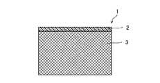
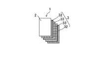
図1、図2、図5に示すように、実施形態1に係る繊維強化樹脂成形品Pの成形用材料1は、最外層2とCFRP層3(繊維強化樹脂層)とにより構成されている。(Embodiment 1)
<Molding materials and fiber reinforced plastic molded products>
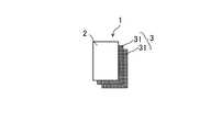
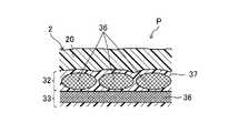
As shown in FIGS. 1, 2, and 5, the
図2、図5に示すように、CFRP層3は、所定方向に配向した強化繊維36に第1熱硬化性樹脂材料37をマトリックスとして含浸させてなるシート状の平織プリプレグ層31(層)が2枚積層されて形成されている。 As shown in FIGS. 2 and 5, the
図5に示すように、本実施形態における平織プリプレグ層31の所定方向に配向した強化繊維36は、限定する意図ではないが例えば平均径5μm〜15μm程度の繊維状の炭素繊維の繊維束が、平織された状態となっている。 As shown in FIG. 5, the reinforcing
なお、本開示技術における所定方向に配向した強化繊維36は、平織状の織物材に限られるものではなく、例えば一定の方向に配向した強化繊維の繊維束が一方向又は多方向に配置されてなる強化繊維材であり、ランダム配向の強化繊維及び不織布を除く強化繊維材であればよい。具体的には例えば、平織に加え、綾織、朱子織等の織物材、平編、リブ編、両面編、パール編、トリコット、ラッセル等の編物材、丸組、平組、角組などの組紐等の組物材、繊維束が一方向に並んだUD材、及び、多方向に積層された繊維束を例えばナイロンやポリエステル等の高分子の糸でステッチ加工してなるノンクリンプファブリック材などが挙げられ、これらの織物材、編物材、組物材、UD材及びノンクリンプファブリック材の1種を単層で用いてもよいし、1種又は複数種を積層させたものを用いてもよい。 The reinforcing
所定方向に配向した強化繊維36としての炭素繊維は、特に限定されるものではないが、例えば、東レ株式会社製T700、東邦テナックス株式会社製HTS40、三菱ケミカル株式会社製TR50S等のポリアクリロニトリル(PAN)系、日本グラファイトファイバー株式会社製XN−60、三菱ケミカル株式会社製K13312等のピッチ系などを使用することができる。 The carbon fiber as the reinforcing
また、本開示技術における所定方向に配向した強化繊維36は、炭素繊維に限定されるものではなく、炭素繊維以外に、ガラスファイバ、バサルトファイバなどにより構成されてもよい。 Further, the reinforcing
第1熱硬化性樹脂材料37は、繊維強化樹脂成形品Pの強度を向上させる観点から、ガラス転移温度Tgが高いものがのぞましく、具体的には例えば、高Tgのエポキシ樹脂、ウレタン、ビニルエステル等が挙げられる。特に、繊維強化樹脂成形品の強度、耐久性、及びコスト性の観点から、エポキシ樹脂が望ましく、この場合、Tgが150℃超200℃以下のものが好ましい。 From the viewpoint of improving the strength of the fiber-reinforced resin molded product P, the first
図1、図2、図5に示すように、最外層2は、成形用材料1の最表面に設けられており、CFRP層3に含有される第1熱硬化性樹脂材料37よりも低Tgの第2熱硬化性樹脂材料20を主成分とし且つ所定方向に配向した強化繊維36を含まない層である。最外層2は、第2熱硬化性樹脂材料20のみからなる構成としてもよいし、衝撃強度向上の観点から、所定方向に配向した強化繊維36以外のランダム配向の強化繊維又は不織布を含有してもよい。なお、含有される強化繊維はランダム配向であるか、又は不織布であるため、第2熱硬化性樹脂材料20を硬化させても、明確な凹凸が現れることはなく表面の平滑性及び外観性を保つことができる。 As shown in FIGS. 1, 2 and 5, the
なお、最外層2に含まれるランダム配向の強化繊維又は不織布は、最外層2とCFRP層3との収縮差を緩和させる観点から、ポリエステル製、セルロース製、ガラス繊維製であることが好ましく、特にポリエステル製であることが好ましい。 The randomly oriented reinforcing fiber or non-woven fabric contained in the
第2熱硬化性樹脂材料20は、第1熱硬化性樹脂材料37と同様に、エポキシ樹脂、ウレタン、ビニルエステル等を用いることができるが、繊維強化樹脂成形品Pの外観性を高める観点から、エポキシ樹脂が望ましい。そして、第2熱硬化性樹脂材料20としては、特に、その組成により、Tgが第1熱硬化性樹脂材料37よりも低いものを用いる。第2熱硬化性樹脂材料20としてエポキシ樹脂を使用する場合、そのTgは、好ましくは120℃以上150℃以下である。 As the second
<繊維強化樹脂成形品の成形方法及び繊維強化樹脂成形品>
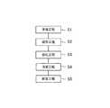
図3に示すように、繊維強化樹脂成形品Pの成形方法は、成形用材料1を準備する準備工程S1と、成形用材料1を金型内にて成形する成形工程S2と、第2熱硬化性樹脂材料20を硬化させる硬化工程S3と、冷却工程S4と、脱型工程S5とを備えている。<Molding method of fiber reinforced resin molded product and fiber reinforced resin molded product>
As shown in FIG. 3, the molding method of the fiber-reinforced resin molded product P includes a preparation step S1 for preparing the
準備工程S1では、例えば、図4に示すロール成形機などを用いて、所定方向に配向した強化繊維36の前駆体シートの表裏両面にシート状の第1熱硬化性樹脂材料37をローラ5で貼り合わせ、ヒータ6で加熱して、前駆体シートに第1熱硬化性樹脂材料37が含浸してなる平織プリプレグ層31を形成する。この平織プリプレグ層31を単独で、又は必要に応じて複数層積層して、CFRP層3を構成する。このとき、実施形態2〜5において後述するように、所定方向に配向した強化繊維36の繊維束の配向が互いに異なる複数のプリプレグ層を積層させてもよい。 In the preparation step S1, for example, using a roll molding machine shown in FIG. 4, a sheet-shaped first
そして、CFRP層3の表面に、第2熱硬化性樹脂材料20からなる最外層2を形成する。具体的には例えば、金型の成形面に最外層2を形成するための第2熱硬化性樹脂材料20からなるサーフェスマットを貼り付ける。その後、サーフェスマット上に上述のごとく形成したCFRP層3を貼り付ける。そうして、金型内に配置された成形用材料1を準備することができる。 Then, the
次に成形工程S2において、金型内に配置された成形用材料1を成形する。成形方法は特に限定されるものではなく、一般的な成形方法を採用することができるが、具体的には例えば、内圧成形、オートクレーブ成形、オーブン成形等により成形することができる。 Next, in the molding step S2, the
例えば、内圧成形を例にとって説明する。内圧成形は、特に袋状やチューブ状の繊維強化樹脂成形品Pを得るのに好適である。成形用材料1が配置された金型を内圧成形用のプレス機内に配置し、金型の温度を、常温から、第1熱硬化性樹脂材料37のTgよりも低く且つ第2熱硬化性樹脂材料20のTgよりも高い温度にまで、限定する意図ではないが例えば30℃/時間〜200℃/時間程度で徐々に昇温させる。また、並行して、内圧用エアを導入し、成形用材料1の内側、すなわち成形用材料1の反金型側から金型の成形面側に向けて圧力を付与する。そうして、昇温により第1及び第2熱硬化性樹脂材料の粘度が低下するとともに、金型の成形面の形状が成形用材料1に転写されて賦形成形される。 For example, internal pressure molding will be described as an example. Internal pressure molding is particularly suitable for obtaining a bag-shaped or tube-shaped fiber-reinforced resin molded product P. The mold on which the
そして、成形工程S2の後に、硬化工程S3において、金型温度を第1熱硬化性樹脂材料37のTgよりも低く且つ第2熱硬化性樹脂材料20のTgよりも高い温度にて、所定時間、限定する意図ではないが例えば1時間〜3時間程度、保持する。これにより、第1熱硬化性樹脂材料37よりも先に最外層2の第2熱硬化性樹脂材料20の硬化が進行する。 Then, after the molding step S2, in the curing step S3, the mold temperature is lower than the Tg of the first
その後、冷却工程S4において、金型温度を降温させ、成形用材料1を冷却する。そして、冷却された成形用材料1を脱型し、図5に示す繊維強化樹脂成形品Pが得られる。 Then, in the cooling step S4, the mold temperature is lowered to cool the
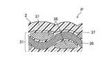
図6に、従来の成形用材料として、最外層2に、マトリクスの第1熱硬化性樹脂材料37のシートを用いて、硬化させた場合の繊維強化樹脂成形品Pの模式的な断面図を示す。この場合、硬化工程S3及び冷却工程S4における第1熱硬化性樹脂材料37の収縮率(30〜50×10−6/℃)と所定方向に配向した強化繊維36の収縮率(−0.3×10−6/℃)との差が大きいため、所定方向に配向した強化繊維36の繊維束の凹凸が繊維強化樹脂成形品Pの表面に現れ、外観性が損なわれる。なお、最外層2を設けず、CFRP層3のみを成形した場合も同様である。FIG. 6 shows a schematic cross-sectional view of a fiber-reinforced resin molded product P when cured by using a sheet of the first
これに対し、本実施形態に係る成形用材料1を用いた成形方法により得られた繊維強化樹脂成形品Pは、図5に示すように、金型の成形面に接する最外層2の第2熱硬化性樹脂材料20が、内側の繊維強化樹脂層の第1熱硬化性樹脂材料37よりも早く硬化することにより、表面に所定方向に配向した強化繊維の凹凸が現れず、表面平滑性及び外観性に優れた繊維強化樹脂成形品Pとなる。 On the other hand, the fiber-reinforced resin molded product P obtained by the molding method using the
なお、上記方法では、金型温度を第1熱硬化性樹脂材料37のTgよりも低く且つ第2熱硬化性樹脂材料20のTgよりも高い温度までしか昇温していないが、硬化工程S3において、第2熱硬化性樹脂材料20が硬化した後に、徐々に第1熱硬化性樹脂材料37の硬化は進行する。なお、硬化工程S3において、第1熱硬化性樹脂材料37のTgよりも低く且つ第2熱硬化性樹脂材料20のTgよりも高い温度で所定時間保持した後に、必要に応じて、金型の温度を第1熱硬化性樹脂材料37のTgよりも高い温度にまで昇温し、第1熱硬化性樹脂材料37を硬化させる工程を設けてもよい。これにより、優れた表面平滑性及び外観性を保持しつつ、内層の第1熱硬化性樹脂材料37を十分に硬化させて、強度の高い繊維強化樹脂成形品を得ることができる。なお、脱型工程S5の後に、得られた繊維強化樹脂成形品Pをオーブンや炉で加熱して第1熱硬化性樹脂材料37の硬化を進めてもよい。 In the above method, the mold temperature is raised only to a temperature lower than Tg of the first
また、上述の方法では、所定方向に配向した強化繊維36の前駆体シートに予め第1熱硬化性樹脂材料37を含浸させてなる平織プリプレグ層31を形成する構成であったが、例えばRTM法などを用いて成形を行ってもよい。具体的には、所定方向に配向した強化繊維36の前駆体シートを所望の枚数積層させたCFRP前駆体層を予め形成しておく。そして、金型内に第2熱硬化性樹脂材料20のサーフィスマットを配置した後、当該CFRP前駆体層をサーフィスマット上へセットし、後から液体状の第1熱硬化性樹脂材料37を金型内に充填して含浸、成形及び硬化をワンポットで行う方法である。本方法によれば、繊維強化樹脂成形品Pの生産性を向上させることができる。 Further, in the above method, the precursor sheet of the reinforcing
成形用材料1は、繊維強化樹脂成形品Pとして、種々のものに適用することができるが、特に車両部品、例えばエンジンカバーなどのエンジン部品、ボンネット、リヤフェンダー、ルーフ、ドア、フロントパネル、リアパネル、リフトゲートなどの車両部品外板部材などに好適に用いることができ、特に好ましくは車両部品外板部材に好適に用いることができる。これにより、軽量且つ高強度の車両部品、特に車両部品外板部材を得ることができる。 The
(実施形態2)
以下、本発明に係る他の実施形態について詳述する。なお、これらの実施形態の説明において、実施形態1と同じ部分については同じ符号を付して詳細な説明を省略する。(Embodiment 2)
Hereinafter, other embodiments according to the present invention will be described in detail. In the description of these embodiments, the same parts as those of the first embodiment are designated by the same reference numerals, and detailed description thereof will be omitted.
図7及び図8に示すように、最外層2とCFRP層3との間に、中間層21を形成してもよい。 As shown in FIGS. 7 and 8, an
中間層21は、最外層2に含有される熱硬化性樹脂材料と同一の熱硬化性樹脂材料、すなわち第2熱硬化性樹脂材料20に、例えばポリエステル、セルロース、ガラス繊維、特に好ましくはポリエステルのランダム配向の強化繊維又は不織布を含有する構成とすることが望ましい。 The
ランダム配向の強化繊維又は不織布を含有する中間層21を備えることにより、繊維強化樹脂成形品Pの衝撃強度が向上する。また、中間層21にはランダム配向の強化繊維又は不織布が含有されているので、第2熱硬化性樹脂材料20のみからなる場合よりも、硬化時の収縮率が小さくなり得る。そうすると、内側のCFRP層3の所定方向に配向した強化繊維36との収縮率の差異が小さくなり、最外層2とCFRP層3との収縮差を緩和することができる。 By providing the
中間層21を設ける場合には、最外層2の第2熱硬化性樹脂材料20のシートと、中間層21とを予め貼り合わせたサーフェスマットを金型内に配置することにより、中間層21を備えた成形用材料1を形成することができる。また、予め貼り合わせたものでなくても、最外層2の第2熱硬化性樹脂材料のシートをサーフェスマットとして金型に配置した後に、中間層21のシートをサーフェスマット上に配置してもよい。 When the
(実施形態3)
実施形態1,2では、CFRP層3は、同一の平織プリプレグ層31を積層させたものであったが、所定方向に配向した強化繊維36の繊維束の配向が互いに異なるプリプレグ層を複数枚積層させたものを用いてもよい。(Embodiment 3)
In the first and second embodiments, the
具体的には、図9及び図10に示すように、UD材の縦プリプレグ層32(層)と、この縦プリプレグ層32の繊維束の配向と直交する向きに繊維束が配向したUD材の横プリプレグ層33(層、なお以下の説明において、縦プリプレグ層32と横プリプレグ層33を併せて「プリプレグ層32,33」と称することがある)を、それぞれ2枚ずつ、積層方向に対して互いに対称となるように積層させてなるCFRP層3としてもよい。なお、プリプレグ層32,33を積層方向に対して互いに対称となるように積層させることにより、繊維強化樹脂成形品の反りなどを抑えることができる。 Specifically, as shown in FIGS. 9 and 10, the vertical prepreg layer 32 (layer) of the UD material and the UD material in which the fiber bundles are oriented in a direction orthogonal to the orientation of the fiber bundles of the
また、本構成においても、実施形態2の構成と同様に、図11に示すように、中間層21を設けてもよい。なお、接着性向上の観点から、図11に示すように、縦プリプレグ層32の表面に、例えば第2熱硬化性樹脂材料20からなる層等の追加の層を設け、その上に中間層21を設け、更にその上に最外層2を設ける構成としてもよい。 Further, in this configuration as well, as in the configuration of the second embodiment, the
なお、図13に示すように、CFRP層3の構成について、UD材からなるプリプレグ層をさらに複数枚積層させる構成としてもよい。具体的には、縦プリプレグ層32と横プリプレグ層33との間に、所定方向に配向した強化繊維36の繊維束の配向が45度の斜プリプレグ層34(層)を配置すると共に、2枚の横プリプレグ層33間に所定方向に配向した強化繊維36の繊維束の配向が斜プリプレグ層34と逆方向に斜め45度に傾いた逆斜プリプレグ層35(層)を2枚配置する構成としてもよい。斜プリプレグ層34及び逆斜プリプレグ層35を配置することにより、CFRP層3の強度が増し、延いては繊維強化樹脂成形品Pの強度が向上する。 As shown in FIG. 13, the
次に、具体的に実施した実施例について説明する。 Next, a concrete example will be described.
(実施例1)
実施例1の成形用材料は、図2及び図5に示す構成である。(Example 1)
The molding material of Example 1 has the configurations shown in FIGS. 2 and 5.
すなわち、2枚の平織プリプレグ層31を積層し、CFRP層3を形成した。 That is, two plain weave prepreg layers 31 were laminated to form the
2枚の平織プリプレグ層31は、縦方向の炭素繊維束と横方向の炭素繊維束とが平織りされた所定方向に配向した強化繊維36にTg170℃程度の市販のエポキシ樹脂を、例えば図4の装置等を用いて、含浸させたものである。 The two plain-woven prepreg layers 31 are made of a reinforcing
Tg130℃程度の市販のエポキシ樹脂の最外層2を、金型の表面にセットしたのち、CFRP層3を金型内のエポキシ樹脂の表面に積層し、金型内に配置された成形用材料1を準備した。 After setting the
成形用材料1が配置された金型を内圧成形用のプレス機にセットし、内圧用エアを注入しながら成形を行った。 The mold on which the
具体的には、常温から約150℃まで120℃/時間程度の速さで金型温度を昇温させた。この間に、エポキシ樹脂の粘度が低下し、内圧による加圧の影響で、金型の表面形状が成形用材料1に転写されることにより、成形を行った。 Specifically, the mold temperature was raised from room temperature to about 150 ° C. at a rate of about 120 ° C./hour. During this period, the viscosity of the epoxy resin decreased, and the surface shape of the mold was transferred to the
そして、金型温度を約150℃一定で1時間保持した。そうして、エポキシ樹脂の硬化を促進し、強度を向上させた。 Then, the mold temperature was kept constant at about 150 ° C. for 1 hour. As a result, the curing of the epoxy resin was promoted and the strength was improved.
その後、金型温度を200℃/時間程度の速さで常温まで冷却した。なお、エポキシ樹脂は、硬化の際及び冷却の際に収縮する。 Then, the mold temperature was cooled to room temperature at a speed of about 200 ° C./hour. The epoxy resin shrinks during curing and cooling.
冷却後、脱型して、繊維強化樹脂成形品Pを得た。 After cooling, the mold was removed to obtain a fiber-reinforced resin molded product P.
繊維強化樹脂成形品Pの表面粗さとして算術平均粗さRaを測定した。 Arithmetic mean roughness Ra was measured as the surface roughness of the fiber-reinforced resin molded product P.
(比較例1)
図6に示すように、エポキシ樹脂の最外層2をTg170℃程度のエポキシ樹脂に変更した以外は、実施例1と同様の方法で繊維強化樹脂成形品Pを得、表面粗さRaを測定した。(Comparative Example 1)
As shown in FIG. 6, a fiber-reinforced resin molded product P was obtained in the same manner as in Example 1 except that the
実施例1及び比較例1の表面粗さRaを表1に示す。 Table 1 shows the surface roughness Ra of Example 1 and Comparative Example 1.

最外層2に低Tgのエポキシ樹脂層を形成した実施例1の繊維強化樹脂成形品Pは、最外層2として内側のCFRP層3と同じ高Tgのエポキシ樹脂の層を形成した比較例1の繊維強化樹脂成形品Pに比べて表面粗さRaが小さくなることが判った。 The fiber-reinforced resin molded product P of Example 1 in which the low Tg epoxy resin layer was formed on the
(実施例2)
CFRP層3の構成を、図9及び図10に示す構成とし、プリプレグ層32,33として、炭素繊維がUDのものを互いに直角に配置した以外は、実施例1と同様に成形及び測定を行った。(Example 2)
The
(実施例3)
図11に示すように、最外層2とCFRP層3との間に、Tg130℃程度のエポキシ樹脂をポリエステル製不織布に含浸させてなるシート状の中間層21を形成した以外は、実施例2と同様に成形及び測定を行った。(Example 3)
As shown in FIG. 11, except that a sheet-shaped
(比較例2)
図12に示すように、エポキシ樹脂の最外層2をTg170℃程度のエポキシ樹脂に変更した以外は、実施例2と同様の方法で繊維強化樹脂成形品Pを得、表面粗さRaを測定した。(Comparative Example 2)
As shown in FIG. 12, a fiber-reinforced resin molded product P was obtained in the same manner as in Example 2 except that the
実施例2,3及び比較例2の表面粗さRaを表2に示す。 Table 2 shows the surface roughness Ra of Examples 2 and 3 and Comparative Example 2.
最外層2に低Tgのエポキシ樹脂層を形成した実施例2の繊維強化樹脂成形品Pは、最外層2も内層と同じ高Tgのエポキシ樹脂層を形成した比較例2の繊維強化樹脂成形品Pに比べて表面粗さRaが小さくなることが判った。 The fiber-reinforced resin molded product P of Example 2 in which the low Tg epoxy resin layer was formed on the
また、最外層2とCFRP層3との間に、中間層21を形成した実施例3の繊維強化樹脂成形品では、実施例2のものよりもさらに表面粗さRaが小さくなることが判った。 Further, it was found that the fiber-reinforced resin molded product of Example 3 in which the
1 成形用材料
2 最外層
20 第2熱硬化性樹脂材料
21 中間層
3 CFRP層(繊維強化樹脂層)
31 平織プリプレグ層(層)
32 縦プリプレグ層(層)
33 横プリプレグ層(層)
34 斜プリプレグ層(層)
35 逆斜プリプレグ層(層)
36 所定方向に配向した強化繊維
37 第1熱硬化性樹脂材料
5 ローラ
6 ヒータ
P 繊維強化樹脂成形品
S1 準備工程
S2 成形工程
S3 硬化工程
S4 冷却工程
S5 脱型工程1
31 Plain weave prepreg layer (layer)
32 Vertical prepreg layer (layer)
33 Horizontal prepreg layer (layer)
34 Oblique prepreg layer (layer)
35 Inverted prepreg layer (layer)
36 Reinforcing fibers oriented in a
Claims (9)
Translated fromJapanese最表面に、ガラス転移温度が上記マトリクスよりも低い第2熱硬化性樹脂材料を主成分とし且つ所定方向に配向した強化繊維を含まない最外層を備え、
上記第1熱硬化性樹脂材料のガラス転移温度は150℃超200℃以下であり、
上記第2熱硬化性樹脂材料のガラス転移温度は120℃以上150℃以下であり、
上記第1熱硬化性樹脂材料及び上記第2熱硬化性樹脂材料は、エポキシ樹脂であることを特徴とする繊維強化樹脂成形品の成形用材料。A material for molding a fiber-reinforced resin molded product, which comprises reinforcing fibers oriented in a predetermined direction and includes a fiber-reinforced resin layer having a matrix of a first thermosetting resin material.
On the outermost surface, an outermost layer containing a second thermosetting resin material having a glass transition temperature lower than that of the above matrix as a main component and not containing reinforcing fibers oriented in a predetermined direction is provided.
The glass transition temperature of the first thermosetting resin material is more than 150 ° C. and 200 ° C. or lower.
The glass transition temperature of the second thermosetting resin material is 120 ° C. or higher and 150 ° C. or lower.
The first thermosetting resin material and the second thermosetting resin material are molding materials for fiber-reinforced resin molded products, which are epoxy resins.
最表面に、ガラス転移温度が上記マトリクスよりも低い第2熱硬化性樹脂材料を主成分とし且つ所定方向に配向した強化繊維を含まない最外層を備え、
上記最外層と、上記繊維強化樹脂層との間に、上記第2熱硬化性樹脂材料にランダム配向の強化繊維又は不織布を含有させてなる中間層を備え、
上記第1熱硬化性樹脂材料及び上記第2熱硬化性樹脂材料は、エポキシ樹脂であることを特徴とする繊維強化樹脂成形品の成形用材料。A material for molding a fiber-reinforced resin molded product, which comprises reinforcing fibers oriented in a predetermined direction and includes a fiber-reinforced resin layer having a matrix of a first thermosetting resin material.
On the outermost surface, an outermost layer containing a second thermosetting resin material having a glass transition temperature lower than that of the above matrix as a main component and not containing reinforcing fibers oriented in a predetermined direction is provided.
An intermediate layer formed by containing a randomly oriented reinforcing fiber or a non-woven fabric in the second thermosetting resin material is provided between the outermost layer and the fiber-reinforced resin layer.
The first thermosetting resin material and the second thermosetting resin material are molding materials for fiber-reinforced resin molded products, which are epoxy resins.
上記ランダム配向の強化繊維又は上記不織布は、ポリエステル製であることを特徴とする繊維強化樹脂成形品の成形用材料。In claim2 ,
The randomly oriented reinforcing fiber or the non-woven fabric is a molding material for a fiber-reinforced resin molded product, which is made of polyester.
上記繊維強化樹脂層は、上記所定方向に配向した強化繊維の配向が異なる複数の層を積層させてなることを特徴とする繊維強化樹脂成形品の成形用材料。The fiber-reinforced resin layer is a material for molding a fiber-reinforced resin molded product, which is formed by laminating a plurality of layers having different orientations of reinforcing fibers oriented in a predetermined direction.
上記所定方向に配向した強化繊維は、炭素繊維であることを特徴とする繊維強化樹脂成形品の成形用材料。The reinforcing fiber oriented in the predetermined direction is a molding material for a fiber-reinforced resin molded product, characterized in that it is a carbon fiber.
上記所定方向に配向した強化繊維は、織物材、編物材、組物材、UD材及びノンクリンプファブリック材の少なくとも1種であることを特徴とする繊維強化樹脂成形品の成形用材料。The reinforcing fiber oriented in a predetermined direction is a material for molding a fiber-reinforced resin molded product, which is at least one of a woven material, a knitted material, a braided material, a UD material, and a non-crimp fabric material.
上記繊維強化樹脂成形品は、車両部品外板部材であることを特徴とする繊維強化樹脂成形品の成形用材料。In any one of claims 1 to 6,
The fiber-reinforced resin molded product is a material for molding a fiber-reinforced resin molded product, which is a vehicle component outer panel member.
上記成形用材料は、最表面に、ガラス転移温度が上記マトリクスよりも低い第2熱硬化性樹脂材料を主成分とし且つ所定方向に配向した強化繊維を含まない最外層を備え、
上記成形用材料を金型内にて成形させる成形工程と、
上記成形用材料を上記第1熱硬化性樹脂材料のガラス転移温度よりも低く且つ上記第2熱硬化性樹脂材料のガラス転移温度よりも高い温度で加熱して、上記第1熱硬化性樹脂材料よりも先に上記第2熱硬化性樹脂材料を硬化させる硬化工程とを備え、
上記第1熱硬化性樹脂材料及び上記第2熱硬化性樹脂材料は、エポキシ樹脂であることを特徴とする繊維強化樹脂成形品の成形方法。A method for molding a fiber-reinforced resin molded product using a molding material containing a fiber-reinforced resin layer containing reinforcing fibers oriented in a predetermined direction and using a first thermosetting resin material as a matrix.
The molding material has an outermost layer on the outermost surface, which is mainly composed of a second thermosetting resin material having a glass transition temperature lower than that of the matrix and does not contain reinforcing fibers oriented in a predetermined direction.
The molding process of molding the above molding material in the mold and
The molding material is heated at a temperature lower than the glass transition temperature of the first thermosetting resin material and higher than the glass transition temperature of the second thermocurable resin material, and the first thermocurable resin material is heated. It is provided with a curing step of curing the second thermosetting resin material prior to the above.
A method for molding a fiber-reinforced resin molded product, wherein the first thermosetting resin material and the second thermosetting resin material are epoxy resins.
上記成形工程は、上記成形用材料を上記金型内に配置した後、該成形用材料の内側から該金型の成形面側に向けて圧力を付与することにより賦形成形する工程であり、
上記硬化工程は、上記金型の温度を昇温させることにより上記第2熱硬化性樹脂材料を硬化させる工程であることを特徴とする繊維強化樹脂成形品の成形方法。
In claim 8.
The molding step is a step of arranging the molding material in the mold and then applying pressure from the inside of the molding material toward the molding surface side of the mold to form the molding.
The curing step is a step of curing the second thermosetting resin material by raising the temperature of the mold, which is a method for molding a fiber-reinforced resin molded product.
Priority Applications (1)
| Application Number | Priority Date | Filing Date | Title |
|---|---|---|---|
| JP2017113525AJP6777017B2 (en) | 2017-06-08 | 2017-06-08 | Molding material and molding method for fiber reinforced plastic molded products |
Applications Claiming Priority (1)
| Application Number | Priority Date | Filing Date | Title |
|---|---|---|---|
| JP2017113525AJP6777017B2 (en) | 2017-06-08 | 2017-06-08 | Molding material and molding method for fiber reinforced plastic molded products |
Publications (2)
| Publication Number | Publication Date |
|---|---|
| JP2018202804A JP2018202804A (en) | 2018-12-27 |
| JP6777017B2true JP6777017B2 (en) | 2020-10-28 |
Family
ID=64954843
Family Applications (1)
| Application Number | Title | Priority Date | Filing Date |
|---|---|---|---|
| JP2017113525AActiveJP6777017B2 (en) | 2017-06-08 | 2017-06-08 | Molding material and molding method for fiber reinforced plastic molded products |
Country Status (1)
| Country | Link |
|---|---|
| JP (1) | JP6777017B2 (en) |
Families Citing this family (3)
| Publication number | Priority date | Publication date | Assignee | Title |
|---|---|---|---|---|
| EP3950249B1 (en) | 2019-03-28 | 2024-12-18 | Toray Industries, Inc. | Molded article of carbon-fiber-reinforced composite material and production method for molded article of carbon-fiber-reinforced composite material |
| US11752708B2 (en)* | 2021-09-10 | 2023-09-12 | The Boeing Company | Uncured composite structures, cured composite structures, and methods of curing uncured composite structures |
| WO2024204015A1 (en)* | 2023-03-27 | 2024-10-03 | 興和株式会社 | Composite fiber-reinforced resin and impact-absorbing material |
Family Cites Families (8)
| Publication number | Priority date | Publication date | Assignee | Title |
|---|---|---|---|---|
| JPS58119851A (en)* | 1982-01-09 | 1983-07-16 | 日東電工株式会社 | Prepreg sheet |
| JPH06270337A (en)* | 1992-01-27 | 1994-09-27 | Matsushita Electric Works Ltd | High heat resistant prepreg |
| JP5293075B2 (en)* | 2007-10-24 | 2013-09-18 | 日立化成株式会社 | Metal foil-clad laminate and printed wiring board |
| JP5609531B2 (en)* | 2010-10-22 | 2014-10-22 | 富士通株式会社 | Printed wiring board, printed wiring board manufacturing method, and electronic device |
| JP5772325B2 (en)* | 2011-07-15 | 2015-09-02 | 大日本印刷株式会社 | Thermosetting resin composition |
| BR112014007044B1 (en)* | 2011-12-09 | 2020-09-24 | Cytec Technology Corp. | SURFACE COATING FILM WITH HIGH RESISTANCE FOR DECAPANTS, STRUCTURE OF THE COMPOSITE AND METHOD FOR MAKING THE STRUCTURE OF THE COMPOSITE |
| JP6102319B2 (en)* | 2012-02-28 | 2017-03-29 | 住友ベークライト株式会社 | Prepreg and prepreg manufacturing method |
| WO2016060062A1 (en)* | 2014-10-17 | 2016-04-21 | 東レ株式会社 | Method for producing fiber-reinforced composite material, resin base and preform |
- 2017
- 2017-06-08JPJP2017113525Apatent/JP6777017B2/enactiveActive
Also Published As
| Publication number | Publication date |
|---|---|
| JP2018202804A (en) | 2018-12-27 |
Similar Documents
| Publication | Publication Date | Title |
|---|---|---|
| US11155046B2 (en) | Fabrication of complex-shaped composite structures | |
| JP5320742B2 (en) | Method for producing composite prepreg substrate, laminated substrate and fiber reinforced plastic | |
| JP4779754B2 (en) | Prepreg laminate and fiber reinforced plastic | |
| JP6777017B2 (en) | Molding material and molding method for fiber reinforced plastic molded products | |
| US20160265157A1 (en) | Structured flock fiber reinforced layer | |
| TW201920398A (en) | Prepreg laminate, method for manufacturing fiber-reinforced plastic using prepreg laminate, and fiber-reinforced plastic | |
| JP2021075811A (en) | Fiber-reinforced composite material sandwich core and manufacturing method of fiber-reinforced composite material sandwich core | |
| JP6665149B2 (en) | Fiber reinforced resin body and method for producing the same | |
| JP4613298B2 (en) | Composite sheet and composite material having smooth surface using the same | |
| US20180222146A1 (en) | Strength enhancing laminar composite material ply layer pre-form and method of manufacturing the same | |
| JP7048956B2 (en) | FRP molded product and its manufacturing method | |
| JP2015147311A (en) | Preform manufacturing method, preform, and fiber-reinforced plastic | |
| JP2014100911A (en) | Preform and production method of the same | |
| JP6211681B2 (en) | Fiber-reinforced composite material and method for producing the same | |
| US20180305551A1 (en) | Resin Composition for FRP, FRP Sheet and Molded Product | |
| JP5966969B2 (en) | Manufacturing method of prepreg | |
| JP4631395B2 (en) | Method for shaping reinforcing fiber base material for FRP molding | |
| JP7387963B2 (en) | Prepreg, prepreg manufacturing method, molded body, and molded body manufacturing method | |
| JP5547412B2 (en) | Planar composite | |
| JP4558398B2 (en) | Composite material with smooth surface | |
| US20240149540A1 (en) | Flat lightweight member and method of producing the same | |
| JP2009012359A (en) | Molding method of frp molded item with foam core | |
| CN107428149A (en) | For forming the stacking material of composite | |
| CN106476299A (en) | A kind of controlled thermoplastic composite honeycomb board of continuous fiber content and preparation method | |
| JP2021055202A (en) | Reinforcement-fiber stitch base material, preform member, and fiber-reinforced composite material, and method of fabricating them |
Legal Events
| Date | Code | Title | Description |
|---|---|---|---|
| A621 | Written request for application examination | Free format text:JAPANESE INTERMEDIATE CODE: A621 Effective date:20180323 | |
| A977 | Report on retrieval | Free format text:JAPANESE INTERMEDIATE CODE: A971007 Effective date:20190121 | |
| A131 | Notification of reasons for refusal | Free format text:JAPANESE INTERMEDIATE CODE: A131 Effective date:20190212 | |
| A601 | Written request for extension of time | Free format text:JAPANESE INTERMEDIATE CODE: A601 Effective date:20190227 | |
| A521 | Written amendment | Free format text:JAPANESE INTERMEDIATE CODE: A523 Effective date:20190612 | |
| A521 | Written amendment | Free format text:JAPANESE INTERMEDIATE CODE: A821 Effective date:20190612 | |
| A131 | Notification of reasons for refusal | Free format text:JAPANESE INTERMEDIATE CODE: A131 Effective date:20191023 | |
| A521 | Written amendment | Free format text:JAPANESE INTERMEDIATE CODE: A523 Effective date:20191220 | |
| A521 | Written amendment | Free format text:JAPANESE INTERMEDIATE CODE: A821 Effective date:20191220 | |
| A131 | Notification of reasons for refusal | Free format text:JAPANESE INTERMEDIATE CODE: A131 Effective date:20200317 | |
| A521 | Written amendment | Free format text:JAPANESE INTERMEDIATE CODE: A523 Effective date:20200515 | |
| TRDD | Decision of grant or rejection written | ||
| A01 | Written decision to grant a patent or to grant a registration (utility model) | Free format text:JAPANESE INTERMEDIATE CODE: A01 Effective date:20200908 | |
| A61 | First payment of annual fees (during grant procedure) | Free format text:JAPANESE INTERMEDIATE CODE: A61 Effective date:20200921 | |
| R150 | Certificate of patent or registration of utility model | Ref document number:6777017 Country of ref document:JP Free format text:JAPANESE INTERMEDIATE CODE: R150 |