JP6775548B2 - Motor control device and air conditioner - Google Patents
Motor control device and air conditionerDownload PDFInfo
- Publication number
- JP6775548B2 JP6775548B2JP2018105557AJP2018105557AJP6775548B2JP 6775548 B2JP6775548 B2JP 6775548B2JP 2018105557 AJP2018105557 AJP 2018105557AJP 2018105557 AJP2018105557 AJP 2018105557AJP 6775548 B2JP6775548 B2JP 6775548B2
- Authority
- JP
- Japan
- Prior art keywords
- current
- motor
- control device
- switching element
- controller
- Prior art date
- Legal status (The legal status is an assumption and is not a legal conclusion. Google has not performed a legal analysis and makes no representation as to the accuracy of the status listed.)
- Active
Links
- 238000001514detection methodMethods0.000claimsdescription19
- 238000006243chemical reactionMethods0.000claimsdescription9
- 239000003507refrigerantSubstances0.000claimsdescription7
- 230000005611electricityEffects0.000claimsdescription2
- 238000010586diagramMethods0.000description20
- 238000000034methodMethods0.000description10
- 230000008569processEffects0.000description8
- 230000002159abnormal effectEffects0.000description6
- 239000003990capacitorSubstances0.000description6
- 238000009499grossingMethods0.000description6
- 230000006870functionEffects0.000description5
- 238000005057refrigerationMethods0.000description4
- 238000001816coolingMethods0.000description3
- 238000010438heat treatmentMethods0.000description3
- 230000008859changeEffects0.000description2
- 238000007710freezingMethods0.000description2
- 230000008014freezingEffects0.000description2
- 230000004048modificationEffects0.000description2
- 238000012986modificationMethods0.000description2
- 230000001629suppressionEffects0.000description2
- 238000004378air conditioningMethods0.000description1
- 238000004891communicationMethods0.000description1
- 230000008020evaporationEffects0.000description1
- 238000001704evaporationMethods0.000description1
- 230000007246mechanismEffects0.000description1
- 239000007787solidSubstances0.000description1
Images


Landscapes
- Air Conditioning Control Device (AREA)
- Control Of Ac Motors In General (AREA)
- Stopping Of Electric Motors (AREA)
Description
Translated fromJapanese本発明は、モータ制御装置、および、空気調和機に関する。 The present invention relates to a motor control device and an air conditioner.
電力変換装置によって駆動されるモータを停止する際、モータに接続された負荷の特性によって逆トルクが発生し、逆転してしまう場合がある。モータが逆転をすると、例えば異常磨耗や異音といった問題が生じる。 When the motor driven by the power converter is stopped, a reverse torque may be generated due to the characteristics of the load connected to the motor, and the motor may reverse. When the motor reverses, problems such as abnormal wear and abnormal noise occur.
外付けのブレーキ回路等を追加せずに逆転を抑制する手段として、例えば特許文献1に記載の技術がある。特許文献1には、上アームおよび下アームのいずれか一方の各相のスイッチング素子を全てオンにして、モータの各相の端子間を短絡させてブレーキ電流を発生させ、スイッチング素子のオンオフ動作の制御によってモータに流れるブレーキ電流を所定の電流制限値に制限する手段が記載されている。 As a means for suppressing reverse rotation without adding an external brake circuit or the like, for example, there is a technique described in
しかしながら、特許文献1に記載の手段は、モータに流れる交流電流を検出する交流電流検出手段を有することを前提としているため、交流電流検出手段を有していない装置については記載が無い。また、ブレーキ電流を所定の電流制限値に制限する手段として、ブレーキを一時的に停止する方法のみが記載されており、スイッチング素子のオンデューティを減少させるという手段については記載が無い。
そこで、本発明は、信頼性の高いモータ制御装置、および、このモータ制御装置を用いた空気調和機を提供することを課題とする。However, since the means described in
Therefore, an object of the present invention is to provide a highly reliable motor control device and an air conditioner using this motor control device.
前記した課題を解決するため、本発明のモータ制御装置は、直流電源の正極に接続される複数のスイッチング素子からなる第1のスイッチング素子群、および前記直流電源の負極に接続される複数のスイッチング素子からなる第2のスイッチング素子群を備え、直流電力を交流電力に変換して電動機を駆動する電力変換回路と、前記電力変換回路の直流側に流れる電流を検出する直流電流検出手段と、前記電力変換回路を駆動するドライブ信号を出力すると共に、前記電動機の停止時には前記第1または第2のスイッチング素子群のいずれか一方のスイッチング素子群を所定のデューティでスイッチングさせるドライブ信号を出力し、前記直流電流検出手段が検出した電流値が予め定めた設定値を超えたならば前記デューティを減少させるデューティ制御モードを第1所定時間が経過するまで実行し、その後に間欠的にモータ電流を検出する間欠電流検出モードを第2所定時間が経過するまで実行する制御器とを備えることを特徴とする。
その他の手段については、発明を実施するための形態のなかで説明する。In order to solve the above-mentioned problems, the motor control device of the present invention includes a first switching element group including a plurality of switching elements connected to the positive electrode of the DC power supply, and a plurality of switchings connected to the negative electrode of the DC power supply. A power conversion circuit including a second switching element group composed of elements and converting DC power into AC power to drive an electric motor, a DC current detecting means for detecting a current flowing on the DC side of the power conversion circuit, and the above-mentioned A drive signal for driving the power conversion circuit is output, and when the electric motor is stopped, a drive signal for switching one of the first or second switching element groups with a predetermined duty is output. When the current value detected by the DC current detecting means exceeds a predetermined set value, theduty control mode for reducing theduty is executed until the first predetermined time elapses, and then the motor current is intermittently detected. It is characterizedby including a controller thatexecutes an intermittent current detection mode until a second predetermined time elapses .
Other means will be described in the form for carrying out the invention.
本発明によれば、信頼性の高いモータ制御装置、および、このモータ制御装置を用いた空気調和機を提供することが可能となる。 According to the present invention, it is possible to provide a highly reliable motor control device and an air conditioner using this motor control device.
以降、本発明を実施するための形態を、各図を参照して詳細に説明する。
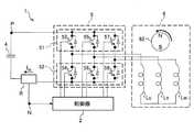
図1は、本実施形態におけるモータ制御装置1の構成図である。
モータ制御装置1は、直流を平滑化する平滑コンデンサ4と、直流を交流に変換して圧縮機モータ6を駆動するインバータモジュール5と、このインバータモジュール5に流れる電源電流を検出するシャント抵抗Rと、インバータモジュール5を制御する制御器2を備えている。制御器2は、例えばCPU(Central Processing Unit)とROM(Read Only Memory)とRAM(Random Access Memory)とA/D変換器を備えたマイコンを有している。このマイコンは、ROMに格納された制御プログラムを実行することにより、インパータモジュール5を制御する。このモータ制御装置1は、圧縮機モータ6のUVW相に接続されており、この圧縮機モータ6を回転駆動する。Hereinafter, a mode for carrying out the present invention will be described in detail with reference to each figure.
FIG. 1 is a configuration diagram of the
The
インバータモジュール5は、6個のスイッチング素子53〜58が三相ブリッジ結線された電力変換回路である。上アーム51には、不図示の直流電源の正極ノードPに接続されるスイッチング素子53,55,57が含まれる。下アーム52には、不図示の直流電源の負極ノードNに接続されるスイッチング素子54,56,58が含まれる。これらスイッチング素子53〜58は、還流ダイオードを含んでおり、ソースからドレインに向かって電流を流す。 The
スイッチング素子53,54は直列接続されて、U相スイッチングレッグを構成する。スイッチング素子53のドレインは、直流電源の正極ノードPに接続される。スイッチング素子53のソースは、スイッチング素子54のドレインに接続され、更に圧縮機モータ6のコイルLuの一端に接続される。スイッチング素子54のソースは、直流電源の負極ノードNに接続される。 The
スイッチング素子55,56は直列接続されて、V相スイッチングレッグを構成する。スイッチング素子55のドレインは、直流電源の正極ノードPに接続される。スイッチング素子55のソースは、スイッチング素子56のドレインに接続され、更に圧縮機モータ6のコイルLvの一端に接続される。スイッチング素子56のソースは、直流電源の負極ノードNに接続される。 The
スイッチング素子57,58は直列接続されて、W相スイッチングレッグを構成する。スイッチング素子57のドレインは、直流電源の正極ノードPに接続される。スイッチング素子57のソースは、スイッチング素子58のドレインに接続され、更に圧縮機モータ6のコイルLwの一端に接続される。スイッチング素子58のソースは、直流電源の負極ノードNに接続される。 The
不図示の直流電源が供給する直流電圧は、正極ノードPと負極ノードNとの間に接続された平滑コンデンサ4によって平滑化されて、インバータモジュール5に印加される。直流/交流変換器であるインバータモジュール5は、制御器2(マイコン)によって制御され、擬似的な三相交流電圧が出力される。この三相交流電圧により圧縮機モータ6に電流が流れ、この圧縮機モータ6を駆動する。 The DC voltage supplied by the DC power supply (not shown) is smoothed by the
圧縮機モータ6に流れる電流は、シャント抵抗Rにてスイッチング素子53〜58に流れる直流電流として検出される。この直流電流は、シャント抵抗Rの両端電圧として検出され、例えば不図示のA/D変換器によって制御器2に取り込まれて監視される。このシャント抵抗RやA/D変換器は、インバータモジュール5の直流側に流れる電流を検出する直流電流検出手段として機能する。 The current flowing through the
制御器2は、6個のスイッチング素子53〜58の制御端子にドライブ信号を出力して、このインバータモジュール5を制御する。圧縮機モータ6は、Y結線されたコイルLu,Lv,Lwに三相交流電流が流されることで、回転子62を回転させる。 The
図2は、モータ制御装置1によるモータの逆転抑制動作を示す図である。
外付けのブレーキ回路等を追加せずに逆転を抑制する手段として、このようにインバータモジュール5の下アーム52の全相をオンして各相を短絡する手段がある。つまり制御器2は、スイッチング素子54,56,58をオンしている。圧縮機モータ6の逆転によって発生する誘起電圧に応じて、コイルLwからコイルLu,Lvに向けて電流が流れる。FIG. 2 is a diagram showing a reverse rotation suppression operation of the motor by the
As a means for suppressing reverse rotation without adding an external brake circuit or the like, there is a means for turning on all phases of the
コイルLuからインバータモジュール5に向けて流れる電流は、スイッチング素子54とスイッチング素子58を介して、再びコイルLwに戻る。コイルLvからインバータモジュール5に向けて流れる電流は、スイッチング素子56とスイッチング素子58を介して、再びコイルLwに戻る。これにより、圧縮機モータ6にはブレーキトルクが発生する。 The current flowing from the coil Lu toward the
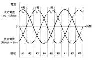
この時の各相に流れる電流は、図3に示すように、回転子の回転角度位置に応じて、順次、電流極性が変化する。 As shown in FIG. 3, the current flowing through each phase at this time sequentially changes in current polarity according to the rotation angle position of the rotor.
図3は、回転子が回転しているときに各相に流れる電流を示すグラフである。領域#1〜#6は、各時刻における電流の流れ方を説明するためのものである。
U相の電流Iuと、V相の電流Ivと、W相の電流Iwは、位相が120度ずつずれた正弦波である。
領域#1において、W相の電流Iwは、正の電流である。ここで正の電流とは、インバータモジュール5から圧縮機モータ6に向かって流れる電流をいう。また、U相の電流IuとV相の電流Ivは、負の電流である。負の電流とは、圧縮機モータ6からインバータモジュール5に向かって流れる電流をいう。FIG. 3 is a graph showing the current flowing through each phase when the rotor is rotating.
The U-phase current Iu, the V-phase current Iv, and the W-phase current Iw are sine waves whose phases are shifted by 120 degrees.
In
領域#2において、U相には負の電流が流れる。また、V相とW相とには、正の電流が流れる。領域#3において、V相には正の電流が流れる。また、W相とU相とには、負の電流が流れる。 In
領域#4において、W相には負の電流が流れる。また、V相とU相とには、正の電流が流れる。領域#5において、U相には正の電流が流れる。また、V相とW相とには、負の電流が流れる。領域#6において、V相には負の電流が流れる。また、W相とU相とには、正の電流が流れる。 In
下アーム52のオンデューティを100%としてオンし続ける場合は、シャント抵抗Rに電流は流れない。しかし、下アーム52のオンデューティが100%未満の場合は、下アーム52がオフの期間に、シャント抵抗Rにシャント電流Ishが流れる。 When the on-duty of the
図4は、各相に流れる電流とシャント電流Ishを示すグラフである。
ここでは、図3に示した領域#1〜#3において、オンデューティが100%未満とした場合の各相モータ電流とシャント電流Ishの関係を示している。
領域#1においてシャント電流Ishは、下アーム52がオフしているときにはU相の電流IuとV相の電流Ivの和であり、下アーム52がオンしているときには0Aとなる。
領域#2においてシャント電流Ishは、下アーム52がオフしているときにはU相の電流Iuと等しく、下アーム52がオンしているときには0Aとなる。
領域3においてシャント電流Ishは、下アーム52がオフしているときにはW相の電流IwとU相の電流Iuの和であり、下アーム52がオンしているときには0Aとなる。FIG. 4 is a graph showing the current flowing through each phase and the shunt current Ish.
Here, in the
In
In
In
図5A〜図5Fは、同じく領域#1〜#3において、各相をオンオフした際のスイッチング状態と電流経路を示した図である。このように、全相を同時にオンオフすることで、シャント抵抗Rに流れる電流から、モータに流れる電流を検出できる。各相の電流分担は不明であるが、最大電流は検出可能であるため、スイッチング素子を保護するという観点で十分に有効な電流検出手段である。 5A to 5F are diagrams showing switching states and current paths when each phase is turned on and off in the
図5Aは、領域#1において下アーム52をオンしたスイッチング状態と電流経路を示す図である。
このとき、W相のコイルLwには、インバータモジュール5から電流が流れる。この電流は、U相のコイルLuとスイッチング素子54に流れると共に、V相のコイルLvとスイッチング素子56にも流れ、スイッチング素子58を介して再びW相のコイルLwに戻る。FIG. 5A is a diagram showing a switching state and a current path in which the
At this time, a current flows from the
図5Bは、領域#1において下アーム52をオフしたスイッチング状態と電流経路を示す図である。
このときもW相のコイルLwには、インバータモジュール5から電流が流れる。この電流は、U相のコイルLuとスイッチング素子53の還流ダイオードに流れると共に、V相のコイルLvとスイッチング素子55の還流ダイオードにも流れ、平滑コンデンサ4とシャント抵抗Rとスイッチング素子58の還流ダイオードを介して再びW相のコイルLwに還流する。
このように、シャント抵抗Rに電流が流れる期間を設けているので、制御器2は、モータ電流を検出することができる。これにより、ブレーキ制御時の最大電流を制御し、パワーモジュールの信頼性を確保することができる。ブレーキ制御の開始タイミングやデューティ増加率を容易に決定することができる。更に、インバータ停止直後からブレーキを開始し、逆転時間を短くすることができる。FIG. 5B is a diagram showing a switching state and a current path in which the
At this time as well, a current flows from the
Since the shunt resistor R is provided with a period during which the current flows in this way, the
図5Cは、領域#2において下アーム52をオンしたスイッチング状態と電流経路を示す図である。
このとき、U相のコイルLuから、インバータモジュール5に向けて電流が流れる。この電流は、スイッチング素子54に流れたのち、スイッチング素子56とコイルLvを介してコイルLuに還流し、更にスイッチング素子58とコイルLwを介してコイルLuに還流する。FIG. 5C is a diagram showing a switching state and a current path in which the
At this time, a current flows from the U-phase coil Lu toward the
図5Dは、領域#2において下アーム52をオフしたスイッチング状態と電流経路を示す図である。
このときもU相のコイルLuから、インバータモジュール5に向けて電流が流れる。この電流は、スイッチング素子53の還流ダイオードと平滑コンデンサ4とシャント抵抗Rに流れたのち、スイッチング素子56の還流ダイオードとコイルLvを介してコイルLuに還流し、更にスイッチング素子58の還流ダイオードとコイルLwを介してコイルLuに還流する。
このように、シャント抵抗Rに電流が流れる期間を設けているので、制御器2は、モータ電流を検出することができる。FIG. 5D is a diagram showing a switching state and a current path in which the
At this time as well, a current flows from the U-phase coil Lu toward the
In this way, since the shunt resistor R is provided with a period during which the current flows, the
図5Eは、領域#3において下アーム52をオンしたスイッチング状態と電流経路を示す図である。
このとき、V相のコイルLvには、インバータモジュール5から電流が流れる。この電流は、U相のコイルLuとスイッチング素子54に流れると共に、W相のコイルLwとスイッチング素子58にも流れ、スイッチング素子56を介して再びV相のコイルLvに戻る。FIG. 5E is a diagram showing a switching state and a current path in which the
At this time, a current flows from the
図5Fは、領域#3において下アーム52をオフしたスイッチング状態と電流経路を示す図である。
このときもV相のコイルLvには、インバータモジュール5から電流が流れる。この電流は、U相のコイルLuとスイッチング素子53の還流ダイオードに流れると共に、W相のコイルLwとスイッチング素子57の還流ダイオードにも流れ、平滑コンデンサ4とシャント抵抗Rとスイッチング素子56の還流ダイオードを介して再びV相のコイルLvに還流する。
このように、シャント抵抗Rに電流が流れる期間を設けているので、制御器2は、モータ電流を検出することができる。FIG. 5F is a diagram showing a switching state and a current path in which the
At this time as well, a current flows from the
In this way, since the shunt resistor R is provided with a period during which the current flows, the
なお、図5Aから図5Fのように上アーム51の全相をオフしつつ下アーム52をオンオフすることに限られず、下アーム52の全相をオフしつつ上アーム51をオンオフしてもよく、限定されない。 It should be noted that it is not limited to turning on / off the
図6は、本実施形態のブレーキ制御の概念図である。
ブレーキ制御開始の後、時間t13が経過するまでは、デューティ制御モードである。デューティ制御モードにおいて、制御器2は、オンデューティをx%(x%は0%以上かつ100%未満)に制限すると共に、検出したシャント電流Ishが所定値を超えたらオンデューティを下げる。そのため、モータ制御装置1は、モータ停止直後からブレーキ制御を開始できる。そして、圧縮機モータ6の最大逆転回転速度を減少させることができる。ここでオンデューティをx%とは、シャント抵抗Rによってモータ電流を検出可能な値に設定されている。FIG. 6 is a conceptual diagram of the brake control of the present embodiment.
The duty control mode is set until the time t13 elapses after the start of the brake control. In the duty control mode, the
なお圧縮機モータ6は、ブレーキ制御が開始したのち時間t11が経過するまでは正転し、時間t11から時間t15まで逆転している。 The
時間t13が経過したのち、時間t14が経過するまでは、図8の間欠電流検出モードである。制御器2は、間欠電流検出モードで動作することにより、モータ電流を検出しつつ、オンデューティを最大にすることができる。 After the time t13 elapses, the intermittent current detection mode of FIG. 8 is performed until the time t14 elapses. By operating in the intermittent current detection mode, the
時間t14が経過したのち、時間t16が経過するまでは、全オン期間である。制御器2は、下アーム52の全相をオンする。このように制御することで、逆転総数を減らして、異常磨耗や異音を減らすことができ、信頼性の高いブレーキ制御を実現することができる。 After the time t14 elapses, the entire on period is until the time t16 elapses. The
図7は、本実施形態のブレーキ制御を示すフローチャートである。
制御器2のマイコンは、ROMに格納されたプログラムを実行することにより、このプレーキ制御を行う。制御器2は、ブレーキ制御を開始すると、上アーム51を全相オフして、下アーム52をPWM制御する(S10)。以下のステップS10〜S15は、図6に示したデューティ制御モードに相当する。FIG. 7 is a flowchart showing the brake control of the present embodiment.
The microcomputer of the
制御器2は、シャント電流Ishが設定値以上か否かを判定する(S11)。シャント電流Ishはモータ電流と等しいので、制御器2は、モータ電流が設定値以上か否かを判定している。ステップS11において、制御器2は、シャント電流Ishが設定値以上ならば、下アーム52のオンデューティを減少させ(S12)、ステップS15の処理に進む。このとき制御器2は、積分制御を行う。制御器2は、シャント電流Ishが設定値未満ならば、ステップS13の処理に進む。 The
ステップS13において、制御器2は、下アーム52のオンデューティが電流検出可能な値(x%)以下であるか否かを判定する。制御器2は、オンデューティが電流検出可能な値以下ならば、オンデューティを線形に増加させて(S14)、ステップS15の処理に進む。制御器2は、オンデューティが電流検出可能な値を超えていたならば、ステップS15の処理に進む。 In step S13, the
ステップS15において、制御器2は、時間t13が経過したか否かを判定する。制御器2は、時間t13が経過していないならば、ステップS10の処理に戻り、時間t13が経過したならば、ステップS16の処理に進む。 In step S15, the
ステップS16〜S19は、下アーム52のオンデューティの100%とx%(例えば93%)とを交互に設定し、間欠的にモータ電流を検出する間欠電流検出モード(図6参照)に相当する。
ステップS16において、制御器2は、第1の期間に亘って下アーム52の全相をオンする。その後、制御器2は、第2の期間に亘って、所定値のオンデューティで下アーム52をPWM制御し(S17)、第1の期間を線形に増加させる(S18)。これにより、ブレーキトルクを最大化することができる。なお、第1の期間は、図8に示す期間P1aや、図9に示す期間P1c〜P1fに相当する。第2の期間は、図8や図9に示す期間P2に相当する。Steps S16 to S19 correspond to an intermittent current detection mode (see FIG. 6) in which 100% and x% (for example, 93%) of the on-duty of the
In step S16, the
ステップS19において、制御器2は、時間t14が経過したか否かを判定する。制御器2は、時間t14が経過していないならば、ステップS16の処理に戻り、時間t14が経過したならば、ステップS20の処理に進む。 In step S19, the
ステップS20において、制御器2は、時間t16が経過するまで下アーム52の全相をオンする。ステップS20は、図6に示した全オン期間に相当する。その後、制御器2は、下アーム52の全相をオフしたのち、図7のブレーキ制御を終了する。 In step S20, the
図8は、間欠電流検出モードの概念図である。
時間t13以前のデューティ制御モードにおいて、制御器2は、PWMキャリアの1周期毎に少なくとも1回は、シャント電流Ishを検出する。マイコンのA/D変換器やスイッチング素子53〜58の特性により、シャント電流Ishを検出のための最小パルス幅が規定される。その結果、オンデューティの最大値が決まってしまう。そこで、時間t13以降の間欠電流検出モードにおいて、制御器2は、PWMキャリアの1周期毎の電流検出を間引き、期間P2のPWMキャリア周期でのみシャント電流Ishを検出し、他の期間P1a,P1bは、オンデューティを100%に設定する。FIG. 8 is a conceptual diagram of the intermittent current detection mode.
In the duty control mode before the time t13, the
図9は、電流検出を行いつつ等価的なオンデューティを増加させる手段の概念図である。
期間P2(第2の期間)は、制御器2がPWM制御する期間である。このように下アーム52のドライブ信号をオフにすることで、シャント抵抗Rにシャント電流Ishを流し、シャント電流Ishを検出することができる。FIG. 9 is a conceptual diagram of means for increasing the equivalent on-duty while detecting the current.
The period P2 (second period) is a period during which the
これに対して期間P1c〜P1f(第1の期間)は、制御器2がオンデューティを100%に設定する期間である。制御器2は、時間経過に応じて期間P1c〜P1fを、期間P2よりも多く出現させている。これにより、制御器2は、PWM制御の間引きの割合を増やしている。 On the other hand, the periods P1c to P1f (first period) are periods in which the
制御器2は、PWM制御の間引きの割合を増やすことで、等価的なオンデューティを増加させ、かつモータ電流を検出することが可能である。電流検出の間引き数が増えるにつれて、オンデューティが100%になる比率も増加し、等価的なオンデューティを増加させるので、ブレーキ力を増大させることができる。なお、モータ回転速度は次第に遅くなっているので、間欠的な電流検出でもオンデューティ調整が可能である。これにより、図6に示す逆転総数を減らすことができる。
なお、間引き数に応じてオンデューティ制御の積分ゲインも増加させる。The
The integrated gain of on-duty control is also increased according to the number of thinning out.
図10は、電流検出を行いつつ等価的なオンデューティを増加させる別の手段の概念図である。
このように、時間経過に応じてPWMキャリアの制御周期を長くすることによっても等価的なオンデューティを増加させながらもモータ電流を検出することが可能である。これにより、図6に示す逆転総数を減らすことができる。FIG. 10 is a conceptual diagram of another means for increasing the equivalent on-duty while performing current detection.
In this way, it is possible to detect the motor current while increasing the equivalent on-duty by lengthening the control cycle of the PWM carrier according to the passage of time. As a result, the total number of reversals shown in FIG. 6 can be reduced.
図11は、本実施形態のモータ制御装置1を用いた空気調和機7の外観図である。
図11に示すように、空気調和機7は、室内機71と、室外機72と、リモコンReとを備えている。室内機71と室外機72とは冷媒配管73で接続され、周知の冷媒サイクルによって、室内機71が設置されている室内を空調する。また、室内機71と室外機72とは、通信ケーブル(図示せず)を介して互いに情報を送受信するようになっている。FIG. 11 is an external view of the air conditioner 7 using the
As shown in FIG. 11, the air conditioner 7 includes an
リモコンReは、ユーザによって操作されて、室内機71に対して赤外線信号を送信する。この赤外線信号の内容は、運転要求、設定温度の変更、タイマ、運転モードの変更、停止要求などの指令である。空気調和機7は、これら赤外線信号の指令に基づいて、冷房モード、暖房モード、除湿モードなどの空調運転を行う。また、室内機71は、リモコンReへ、室温情報、湿度情報、電気代情報などのデータを送信する。
図12は、空気調和機7の構成を示すブロック図である。
空気調和機7は、圧縮機61、室内熱交換器79、室内膨張弁74、室外熱交換器78、アキュムレータ76を順次連結して冷媒を循環させ冷凍サイクルを形成している。そして、室内を冷房する場合、圧縮機61で圧縮された冷媒は室外熱交換器78で凝縮して液化した後、室内膨張弁74で減圧し、室内熱交換器79で蒸発して圧縮機61に戻る。室内送風機用電動機75は室内機71の熱交換を促進し、室外送風機用電動機77は室外機72の熱交換を促進する。The remote controller Re is operated by the user to transmit an infrared signal to the
FIG. 12 is a block diagram showing the configuration of the air conditioner 7.
In the air conditioner 7, the
圧縮機61は、冷凍サイクルに必要とされる能力に関連して運転周波数を可変制御される圧縮機モータ6により駆動され、運転周波数は、図1に示したモータ制御装置1により制御される。
冷凍サイクルは、圧縮機61の回転速度以外に冷媒流量を調整する室内膨張弁74、あるいは室外膨脹弁(図示せず)の開度、室内送風機用電動機75および室外送風機用電動機77の回転速度、冷房/暖房の運転モードを切り換える四方弁(図示せず)などが制御される。そのための情報として運転モード、温度設定などを行うリモコンReによる操作指令信号、各部の温度(圧縮機61の吐出ガス温度、外気温度、熱交換器温度、蒸発温度、吸込温度、吹出温度、凍結温度、ガス管温度など)および圧力(圧縮機61の吸入圧力、吐出圧力)を検出した信号などが、この空気調和機7の制御部(不図示)に入力される。The
In the refrigeration cycle, the opening degree of the indoor expansion valve 74 or the outdoor expansion valve (not shown) that adjusts the refrigerant flow rate in addition to the rotation speed of the
不図示の制御部へ入力される検出信号および指令信号は、制御器2へ入力される。これより、冷凍サイクル制御をモータ制御装置1などで行い、各種制御機構(室外膨脹弁、室外送風機用電動機77、冷房/暖房の運転モードを切り換える四方弁)を制御することができる。これにより、圧縮機61に搭載された圧縮機モータ6のブレーキ制御における異常磨耗や異音を減らすことができ、信頼性の高いブレーキ制御を実現することができる。 The detection signal and the command signal input to the control unit (not shown) are input to the
《変形例》
本発明は上記した実施形態に限定されるものではなく、様々な変形例が含まれる。例えば上記した実施形態は、本発明を分かりやすく説明するために詳細に説明したものであり、必ずしも説明した全ての構成を備えるものに限定されるものではない。ある実施形態の構成の一部を他の実施形態の構成に置き換えることが可能であり、ある実施形態の構成に他の実施形態の構成を加えることも可能である。また、各実施形態の構成の一部について、他の構成の追加・削除・置換をすることも可能である。<< Modification example >>
The present invention is not limited to the above-described embodiment, and includes various modifications. For example, the above-described embodiment has been described in detail in order to explain the present invention in an easy-to-understand manner, and is not necessarily limited to the one including all the described configurations. It is possible to replace a part of the configuration of one embodiment with the configuration of another embodiment, and it is also possible to add the configuration of another embodiment to the configuration of one embodiment. Further, it is also possible to add / delete / replace a part of the configuration of each embodiment with another configuration.
上記の各構成、機能、処理部、処理手段などは、それらの一部または全部を、例えば集積回路などのハードウェアで実現してもよい。上記の各構成、機能などは、プロセッサがそれぞれの機能を実現するプログラムを解釈して実行することにより、ソフトウェアで実現してもよい。各機能を実現するプログラム、テーブル、ファイルなどの情報は、メモリ、ハードディスク、SSD(Solid State Drive)などの記録装置、または、フラッシュメモリカード、DVD(Digital Versatile Disk)などの記録媒体に置くことができる。 Each of the above configurations, functions, processing units, processing means, and the like may be partially or wholly realized by hardware such as an integrated circuit. Each of the above configurations, functions, and the like may be realized by software by the processor interpreting and executing a program that realizes each function. Information such as programs, tables, and files that realize each function can be placed in a memory, hard disk, recording device such as SSD (Solid State Drive), or recording medium such as flash memory card or DVD (Digital Versatile Disk). it can.
各実施形態に於いて、制御線や情報線は、説明上必要と考えられるものを示しており、製品上必ずしも全ての制御線や情報線を示しているとは限らない。実際には、殆ど全ての構成が相互に接続されていると考えてもよい。 In each embodiment, the control lines and information lines indicate what is considered necessary for explanation, and the product does not necessarily indicate all the control lines and information lines. In practice, it can be considered that almost all configurations are interconnected.
1 モータ制御装置
2 制御器
4 平滑コンデンサ
5 インバータモジュール (電力変換回路)
51 上アーム (第1のスイッチング素子群)
52 下アーム (第2のスイッチング素子群)
53〜58 スイッチング素子
6 圧縮機モータ
7 空気調和機
71 室内機
72 室外機
73 冷媒配管
74 室内膨張弁 (膨張弁)
75 室内送風機用電動機
76 アキュムレータ (凝縮器)
77 室外送風機用電動機
78 室外熱交換器 (蒸発器)
79 室内熱交換器 (蒸発器)
Re リモコン
R シャント抵抗 (直流電流検出手段)1
51 Upper arm (first switching element group)
52 Lower arm (second switching element group)
53 to 58
75 Electric motor for
77 Electric motor for
79 Indoor heat exchanger (evaporator)
Re remote control R shunt resistor (DC current detecting means)
Claims (8)
Translated fromJapanese前記電力変換回路の直流側に流れる電流を検出する直流電流検出手段と、
前記電力変換回路を駆動するドライブ信号を出力すると共に、前記電動機の停止時には前記第1または第2のスイッチング素子群のいずれか一方のスイッチング素子群を所定のデューティでスイッチングさせるドライブ信号を出力し、前記直流電流検出手段が検出した電流値が予め定めた設定値を超えたならば前記デューティを減少させるデューティ制御モードを第1所定時間が経過するまで実行し、その後に間欠的にモータ電流を検出する間欠電流検出モードを第2所定時間が経過するまで実行する制御器と、
を備えることを特徴とするモータ制御装置。A first switching element group composed of a plurality of switching elements connected to the positive side of the DC power supply and a second switching element group composed of a plurality of switching elements connected to the negative side of the DC power supply are provided, and DC power is exchanged. A power conversion circuit that converts electricity into electric power to drive an electric motor,
A DC current detecting means for detecting the current flowing on the DC side of the power conversion circuit, and
A drive signal for driving the power conversion circuit is output, and a drive signal for switching one of the first or second switching element groups with a predetermined duty is output when the electric motor is stopped. When the current value detected by the DC current detecting means exceeds a predetermined set value, theduty control mode for reducing theduty is executed until the first predetermined time elapses, and then the motor current is intermittently detected. A controller thatexecutes the intermittent current detection mode until the second predetermined time elapses ,
A motor control device characterized by comprising.
ことを特徴とする請求項1に記載のモータ制御装置。 The motor control device according to claim 1.
ことを特徴とする請求項1または2に記載のモータ制御装置。 The motor control device according to claim 1 or 2.
ことを特徴とする請求項1に記載のモータ制御装置。In theduty control mode, thecontroller limits the duty to a predetermined value at which the DC current detecting means can detect a current flowing on the DC side of the power conversion circuit.
The motor control device according to claim 1.
ことを特徴とする請求項1から4のうち何れか1項に記載のモータ制御装置。In theintermittent current detection mode, the controller generates a drive signal by PWM control and lengthens the control cycle of PWM control according to the passage of time.
The motor control device according toany one of claims 1to 4, wherein the motor control device is characterized.
ことを特徴とする請求項1から5のうち何れか1項に記載のモータ制御装置。In theintermittent current detection mode, the controller generates a drive signal by PWM control, outputs a drive signal that turns on the switching element group over one cycle of the PWM control cycle, and PWM control. It has a second period for outputting a drive signal that turns off the switching element group during the cycle, and causes the first period to appear more than the second period with the passage of time.
The motor control device according toany one of claims 1to 5, wherein the motor control device is characterized.
ことを特徴とする請求項1から5のいずれかに記載のモータ制御装置。The controller generates a drive signal by PWM control when the electric motor is stopped, and outputs a drive signal that turns off the switching element group at a predetermined timing during the PWM control cycle.
The motor control device according to any one of claims 1 to5 .
前記電動機によって駆動される圧縮機と、凝縮器と、膨張弁と、蒸発器と、によってなる冷媒回路を備えることを特徴とする空気調和機。The motor control device according to any one of claims 1 to7 is provided, and the motor control device is provided.
An air conditioner including a refrigerant circuit including a compressor driven by the electric motor, a condenser, an expansion valve, and an evaporator.
Priority Applications (1)
| Application Number | Priority Date | Filing Date | Title |
|---|---|---|---|
| JP2018105557AJP6775548B2 (en) | 2018-05-31 | 2018-05-31 | Motor control device and air conditioner |
Applications Claiming Priority (1)
| Application Number | Priority Date | Filing Date | Title |
|---|---|---|---|
| JP2018105557AJP6775548B2 (en) | 2018-05-31 | 2018-05-31 | Motor control device and air conditioner |
Related Child Applications (1)
| Application Number | Title | Priority Date | Filing Date |
|---|---|---|---|
| JP2020167461ADivisionJP7153697B2 (en) | 2020-10-02 | 2020-10-02 | Motor controller and air conditioner |
Publications (2)
| Publication Number | Publication Date |
|---|---|
| JP2019213301A JP2019213301A (en) | 2019-12-12 |
| JP6775548B2true JP6775548B2 (en) | 2020-10-28 |
Family
ID=68845502
Family Applications (1)
| Application Number | Title | Priority Date | Filing Date |
|---|---|---|---|
| JP2018105557AActiveJP6775548B2 (en) | 2018-05-31 | 2018-05-31 | Motor control device and air conditioner |
Country Status (1)
| Country | Link |
|---|---|
| JP (1) | JP6775548B2 (en) |
Families Citing this family (2)
| Publication number | Priority date | Publication date | Assignee | Title |
|---|---|---|---|---|
| JP2023056894A (en)* | 2021-10-08 | 2023-04-20 | パナソニックIpマネジメント株式会社 | Cleaner connectable to collection device |
| WO2024247146A1 (en)* | 2023-05-31 | 2024-12-05 | 三菱電機モビリティ株式会社 | Motor control device, electric power steering device, and vehicle |
Family Cites Families (5)
| Publication number | Priority date | Publication date | Assignee | Title |
|---|---|---|---|---|
| JPS63190578A (en)* | 1987-02-03 | 1988-08-08 | Toshiba Corp | DC braking circuit in inverter equipment |
| JP5032184B2 (en)* | 2007-04-16 | 2012-09-26 | 富士通テレコムネットワークス株式会社 | Motor control circuit |
| JP5968805B2 (en)* | 2013-02-28 | 2016-08-10 | 日立オートモティブシステムズ株式会社 | Motor device and motor drive device |
| CN107836077B (en)* | 2015-07-09 | 2020-07-07 | 三菱电机株式会社 | motor control device |
| JP2018042297A (en)* | 2016-09-05 | 2018-03-15 | 日立ジョンソンコントロールズ空調株式会社 | Motor controller and air conditioner |
- 2018
- 2018-05-31JPJP2018105557Apatent/JP6775548B2/enactiveActive
Also Published As
| Publication number | Publication date |
|---|---|
| JP2019213301A (en) | 2019-12-12 |
Similar Documents
| Publication | Publication Date | Title |
|---|---|---|
| CN103828214B (en) | The control method of heat pump assembly, heat pump and inverter | |
| EP2779406B1 (en) | Power converter and air conditioner having the same | |
| KR0122095B1 (en) | Inverter and air-conditioner driven by the same | |
| JP2019176554A (en) | Motor drive device | |
| WO2005067131A1 (en) | Driving method and driver of brushless dc motor | |
| JP7387038B2 (en) | Power converters, motor drives and air conditioners | |
| JP6775548B2 (en) | Motor control device and air conditioner | |
| JP5063570B2 (en) | Fan drive device and air conditioner equipped with the same | |
| WO2022091184A1 (en) | Power converter, motor driver, and equipment used in refrigeration cycle applied | |
| US20220224276A1 (en) | Motor driving device and air conditioner including the same | |
| JP7055237B2 (en) | Power converter and air conditioner using it | |
| JP2008005592A (en) | Motor drive device and storage device equipped with the motor drive device | |
| WO2016046993A1 (en) | Heat pump device, air-conditioner equipped with same, heat pump water heater, refrigerator, and refrigerating machine | |
| JP7153697B2 (en) | Motor controller and air conditioner | |
| JP4436651B2 (en) | Refrigeration cycle equipment | |
| CN116783810A (en) | Power conversion device, motor drive device, and refrigeration cycle application device | |
| WO2018142738A1 (en) | Air conditioner | |
| KR20080088114A (en) | Electric compressors and air conditioners, including them | |
| WO2017183179A1 (en) | Electric motor drive device and refrigeration cycle device | |
| CN116964917A (en) | Power conversion devices and air conditioners | |
| WO2021048895A1 (en) | Compressor drive device, and air conditioning device | |
| JP7241968B2 (en) | air conditioner | |
| WO2018043258A1 (en) | Power conversion device and air conditioner equipped with same | |
| KR102063633B1 (en) | Power converting apparatus and home appliance including the same | |
| KR102260446B1 (en) | Power converting apparatus and home appliance including the same |
Legal Events
| Date | Code | Title | Description |
|---|---|---|---|
| A621 | Written request for application examination | Free format text:JAPANESE INTERMEDIATE CODE: A621 Effective date:20190614 | |
| A131 | Notification of reasons for refusal | Free format text:JAPANESE INTERMEDIATE CODE: A131 Effective date:20200526 | |
| A521 | Written amendment | Free format text:JAPANESE INTERMEDIATE CODE: A523 Effective date:20200727 | |
| TRDD | Decision of grant or rejection written | ||
| A01 | Written decision to grant a patent or to grant a registration (utility model) | Free format text:JAPANESE INTERMEDIATE CODE: A01 Effective date:20200908 | |
| A61 | First payment of annual fees (during grant procedure) | Free format text:JAPANESE INTERMEDIATE CODE: A61 Effective date:20201006 | |
| R150 | Certificate of patent or registration of utility model | Ref document number:6775548 Country of ref document:JP Free format text:JAPANESE INTERMEDIATE CODE: R150 |