Movatterモバイル変換


[0]ホーム

URL:


JP6775455B2 - Rectifier circuit for distributed power generator - Google Patents

Rectifier circuit for distributed power generator
Download PDF

Info

Publication number
JP6775455B2
JP6775455B2JP2017059830AJP2017059830AJP6775455B2JP 6775455 B2JP6775455 B2JP 6775455B2JP 2017059830 AJP2017059830 AJP 2017059830AJP 2017059830 AJP2017059830 AJP 2017059830AJP 6775455 B2JP6775455 B2JP 6775455B2
Authority
JP
Japan
Prior art keywords
rectifier
capacitor
circuit
phase
distributed power
Prior art date
Legal status (The legal status is an assumption and is not a legal conclusion. Google has not performed a legal analysis and makes no representation as to the accuracy of the status listed.)
Active
Application number
JP2017059830A
Other languages
Japanese (ja)
Other versions
JP2018164348A (en
Inventor
松田 真一
真一 松田
真二 窪田
真二 窪田
塩田 剛
剛 塩田
Current Assignee (The listed assignees may be inaccurate. Google has not performed a legal analysis and makes no representation or warranty as to the accuracy of the list.)
Toyo Electric Manufacturing Ltd
Original Assignee
Toyo Electric Manufacturing Ltd
Priority date (The priority date is an assumption and is not a legal conclusion. Google has not performed a legal analysis and makes no representation as to the accuracy of the date listed.)
Filing date
Publication date
Application filed by Toyo Electric Manufacturing LtdfiledCriticalToyo Electric Manufacturing Ltd
Priority to JP2017059830ApriorityCriticalpatent/JP6775455B2/en
Publication of JP2018164348ApublicationCriticalpatent/JP2018164348A/en
Application grantedgrantedCritical
Publication of JP6775455B2publicationCriticalpatent/JP6775455B2/en
Activelegal-statusCriticalCurrent
Anticipated expirationlegal-statusCritical

Links

Images

Landscapes

Description

Translated fromJapanese

本発明は分散電源用発電装置の整流回路に関する。 The present invention relates to a rectifier circuit of a power generation device for distributed power sources.

分散電源用発電装置の整流回路は、例えばコンデンサ、リアクトルおよび整流器で構成される。 The rectifier circuit of the distributed power generation device is composed of, for example, a capacitor, a reactor and a rectifier.

例えば、特許文献1には従来の分散電源用発電装置の整流回路の一例が開示されている。 For example, Patent Document 1 discloses an example of a rectifier circuit of a conventional power generation device for distributed power sources.

特開2013−21849号公報Japanese Unexamined Patent Publication No. 2013-21849

例えば、特許文献1の整流回路は、2倍昇圧回路を備えることによって、発電機の回転数がある程度低い場合にも電力を出力できる。しかし、発電機電圧がパワーコンディショナの動作電圧以下、直流電源の電圧以下においても電力を出力できる整流回路が求められていた。 For example, the rectifier circuit of Patent Document 1 can output electric power even when the rotation speed of the generator is low to some extent by providing a double booster circuit. However, there has been a demand for a rectifier circuit capable of outputting electric power even when the generator voltage is lower than the operating voltage of the power conditioner and lower than the voltage of the DC power supply.

かかる事情に鑑みてなされた本発明の目的は、発電機の回転数が低い場合においても電力を出力できる分散電源用発電装置の整流回路を提供することにある。 An object of the present invention made in view of such circumstances is to provide a rectifier circuit of a power generation device for a distributed power source that can output electric power even when the rotation speed of the generator is low.

前記課題を解決するため、本発明の実施形態に係る分散電源用発電装置の整流回路は、風車または水車によって駆動される永久磁石型発電機からの交流電力を直流電力に変換して出力する分散電源用発電装置の整流回路であって、前記永久磁石型発電機に接続される第1の整流器と、前記永久磁石型発電機に一端が接続される第1のコンデンサと、第2のコンデンサを介して前記第1のコンデンサの他端と接続される第2の整流器と、前記第1のコンデンサの他端と接続される第3の整流器と、第3のコンデンサを介して前記第1のコンデンサの他端と接続される第4の整流器と、を備え、前記第1の整流器に並列に、前記第2の整流器と、前記第3の整流器と、前記第4の整流器と、が直列に接続されて直流電力を出力する。 In order to solve the above problems, the rectifier circuit of the distributed power generation device according to the embodiment of the present invention converts AC power from a permanent magnet type generator driven by a windmill or a water wheel into DC power and outputs it. A rectifier circuit of a power generation device, the first rectifier connected to the permanent magnet type generator, the first capacitor connected to one end of the permanent magnet type generator, and the second capacitor. A second rectifier connected to the other end of the first capacitor via the third rectifier, a third rectifier connected to the other end of the first capacitor, and the first rectifier via the third capacitor. A fourth rectifier connected to the other end of the rectifier is provided, and the second rectifier, the third rectifier, and the fourth rectifier are connected in series in parallel with the first rectifier. It is output DC power.

また、本発明の実施形態に係る分散電源用発電装置の整流回路は、前記第1の整流器、前記第2の整流器、前記第3の整流器および前記第4の整流器が、それぞれ、三組のダイオードを備える三相全波整流回路であってもよい。 Further, in the rectifier circuit of the power generation device for distributed power supply according to the embodiment of the present invention, the first rectifier, the second rectifier, the third rectifier and the fourth rectifier each have three sets of diodes. It may be a three-phase full-wave rectifier circuit including.

本発明の実施形態によれば、発電機の回転数が低い場合においても電力を出力できる分散電源用発電装置の整流回路を提供することができる。 According to the embodiment of the present invention, it is possible to provide a rectifier circuit of a power generation device for a distributed power source that can output electric power even when the rotation speed of the generator is low.

本発明の一実施形態に係る分散電源用発電装置の整流回路を例示する図である。It is a figure which illustrates the rectifier circuit of the power generation apparatus for distributed power sources which concerns on one Embodiment of this invention.本発明の一実施形態における3倍昇圧回路を説明する図である。It is a figure explaining the triple booster circuit in one Embodiment of this invention.本発明の一実施形態における3倍昇圧回路を説明する図である。It is a figure explaining the triple booster circuit in one Embodiment of this invention.本発明の一実施形態における3倍昇圧回路を説明する図である。It is a figure explaining the triple booster circuit in one Embodiment of this invention.本発明の一実施形態に係る分散電源用発電装置の整流回路の近似出力特性を示す図である。It is a figure which shows the approximate output characteristic of the rectifier circuit of the power generation apparatus for distributed power sources which concerns on one Embodiment of this invention.比較例の分散電源用発電装置の整流回路を例示する図である。It is a figure which illustrates the rectifier circuit of the power generation apparatus for distributed power sources of a comparative example.

以下、本発明の実施形態について、図を参照して説明する。 Hereinafter, embodiments of the present invention will be described with reference to the drawings.

(整流回路の構成)
図1は本実施形態に係る分散電源用発電装置の整流回路10の図である。
(Rectifier circuit configuration)
FIG. 1 is a diagram of arectifier circuit 10 of a power generation device for distributed power sources according to the present embodiment.

整流回路10は、永久磁石型発電機2とともに分散電源用発電装置を構成する。本実施形態において、永久磁石型発電機2は風車1によって駆動されて交流電力を出力する。分散電源用発電装置は、永久磁石型発電機2からの交流電力を直流電力に変換して出力する。本実施形態において、分散電源用発電装置の整流回路10から出力された直流電力によって直流電源5が充電される。直流電源5は例えばリチウムイオン電池のような二次電池であってもよい。また、別の実施形態として、風車1に代えて水車が用いられてもよい。 Therectifier circuit 10 constitutes a distributed power generation device together with the permanentmagnet type generator 2. In the present embodiment, the permanentmagnet type generator 2 is driven by the wind turbine 1 to output AC power. The distributed power generation device converts the AC power from the permanentmagnet type generator 2 into DC power and outputs it. In the present embodiment, the DC power supply 5 is charged by the DC power output from the rectifyingcircuit 10 of the distributed power generation device. The DC power supply 5 may be a secondary battery such as a lithium ion battery. Further, as another embodiment, a water turbine may be used instead of the wind turbine 1.

整流回路10は、第1の整流器37と、第2の整流器34と、第3の整流器35と、第4の整流器36と、第1のコンデンサ31と、第2のコンデンサ32と、第3のコンデンサ33と、を備える。詳細については後述するが、整流回路10の3倍昇圧回路30は、第2の整流器34と、第3の整流器35と、第4の整流器36と、第2のコンデンサ32と、第3のコンデンサ33と、で構成される。 Therectifier circuit 10 includes afirst rectifier 37, asecond rectifier 34, athird rectifier 35, afourth rectifier 36, afirst capacitor 31, asecond capacitor 32, and athird rectifier circuit 10. It includes acapacitor 33. Although the details will be described later, thetriple booster circuit 30 of therectifier circuit 10 includes asecond rectifier 34, athird rectifier 35, afourth rectifier 36, asecond capacitor 32, and a third capacitor. It is composed of 33 and.

第1の整流器37は永久磁石型発電機2に接続される。より具体的には、第1の整流器37は永久磁石型発電機2の交流電力の出力端子(交流出力端子)に接続される。また、第1の整流器37は、永久磁石型発電機2からの交流電力を変換した直流電力を出力して、直流電源5に供給する。本実施形態において、第1の整流器37は、後述する第2の整流器34、第3の整流器35および第4の整流器36と同様に、三組(6つ)のダイオードを備える三相全波整流回路である。第1の整流器37における各組の上段側のダイオードと下段側のダイオードとの接続点が、永久磁石型発電機2に接続される。 Thefirst rectifier 37 is connected to the permanentmagnet type generator 2. More specifically, thefirst rectifier 37 is connected to the AC power output terminal (AC output terminal) of the permanentmagnet type generator 2. Further, thefirst rectifier 37 outputs DC power converted from AC power from the permanentmagnet type generator 2 and supplies it to the DC power source 5. In the present embodiment, thefirst rectifier 37 is a three-phase full-wave rectifier including three sets (six) of diodes, like thesecond rectifier 34, thethird rectifier 35, and thefourth rectifier 36, which will be described later. It is a circuit. The connection point between the upper diode and the lower diode of each set in thefirst rectifier 37 is connected to the permanentmagnet type generator 2.

第1のコンデンサ31は永久磁石型発電機2に接続される。より具体的には、第1のコンデンサ31は永久磁石型発電機2の交流電力の出力端子(交流出力端子)に一端が接続される。第1のコンデンサ31の他端は3倍昇圧回路30と接続される。第1のコンデンサ31は交流電力を伝送する。つまり、永久磁石型発電機2からの交流電力は、第1のコンデンサ31を介して3倍昇圧回路30に供給される。 Thefirst capacitor 31 is connected to the permanentmagnet type generator 2. More specifically, one end of thefirst capacitor 31 is connected to an AC power output terminal (AC output terminal) of the permanentmagnet type generator 2. The other end of thefirst capacitor 31 is connected to thetriple booster circuit 30. Thefirst capacitor 31 transmits AC power. That is, the AC power from the permanentmagnet type generator 2 is supplied to thetriple booster circuit 30 via thefirst capacitor 31.

第2のコンデンサ32は3倍昇圧回路30における上段側の昇圧コンデンサである。第2のコンデンサ32の一端は、第1のコンデンサ31の他端(永久磁石型発電機2に接続されていない方の端子)と接続される。また、第2のコンデンサ32の他端(第1のコンデンサ31に接続されていない方の端子)は、第2の整流器34と接続される。 Thesecond capacitor 32 is a boosting capacitor on the upper stage side of thetriple booster circuit 30. One end of thesecond capacitor 32 is connected to the other end of the first capacitor 31 (the terminal not connected to the permanent magnet type generator 2). Further, the other end of the second capacitor 32 (the terminal not connected to the first capacitor 31) is connected to thesecond rectifier 34.

第3のコンデンサ33は3倍昇圧回路30における下段側の昇圧コンデンサである。第3のコンデンサ33の一端は、第1のコンデンサ31の他端と接続される。また、第3のコンデンサ33の他端(第1のコンデンサ31に接続されていない方の端子)は、第4の整流器36と接続される。 Thethird capacitor 33 is a booster capacitor on the lower stage side of thetriple booster circuit 30. One end of thethird capacitor 33 is connected to the other end of thefirst capacitor 31. Further, the other end of the third capacitor 33 (the terminal not connected to the first capacitor 31) is connected to thefourth rectifier 36.

第2の整流器34は、第2のコンデンサ32を介して第1のコンデンサ31の他端と接続される。本実施形態において、第2の整流器34は、三組(6つ)のダイオードを備える三相全波整流回路である。第2の整流器34における各組の上段側のダイオードと下段側のダイオードとの接続点が、第2のコンデンサ32の他端と接続される。また、第2の整流器34の高電位側のノードは、第1の整流器37の高電位側のノードおよび直流電源5の高電位側の端子と接続される。また、第2の整流器34の低電位側のノードは、第3の整流器35の高電位側のノードと接続される。つまり、第2の整流器34は第3の整流器35と直列に接続される。 Thesecond rectifier 34 is connected to the other end of thefirst capacitor 31 via thesecond capacitor 32. In the present embodiment, thesecond rectifier 34 is a three-phase full-wave rectifier circuit including three sets (six) of diodes. The connection point between the upper diode and the lower diode of each set in thesecond rectifier 34 is connected to the other end of thesecond capacitor 32. Further, the node on the high potential side of thesecond rectifier 34 is connected to the node on the high potential side of thefirst rectifier 37 and the terminal on the high potential side of the DC power supply 5. Further, the node on the low potential side of thesecond rectifier 34 is connected to the node on the high potential side of thethird rectifier 35. That is, thesecond rectifier 34 is connected in series with thethird rectifier 35.

第3の整流器35は第1のコンデンサ31の他端と接続される。本実施形態において、第3の整流器35は、三組(6つ)のダイオードを備える三相全波整流回路である。第3の整流器35における各組の上段側のダイオードと下段側のダイオードとの接続点が、第1のコンデンサ31の他端と接続される。また、上記のように、第3の整流器35の高電位側のノードは、第2の整流器34の低電位側のノードと接続される。また、第3の整流器35の低電位側のノードは、第4の整流器36の高電位側のノードと接続される。つまり、第3の整流器35は第4の整流器36と直列に接続される。 Thethird rectifier 35 is connected to the other end of thefirst capacitor 31. In this embodiment, thethird rectifier 35 is a three-phase full-wave rectifier circuit including three sets (six) of diodes. The connection point between the upper diode and the lower diode of each set in thethird rectifier 35 is connected to the other end of thefirst capacitor 31. Further, as described above, the node on the high potential side of thethird rectifier 35 is connected to the node on the low potential side of thesecond rectifier 34. Further, the node on the low potential side of thethird rectifier 35 is connected to the node on the high potential side of thefourth rectifier 36. That is, thethird rectifier 35 is connected in series with thefourth rectifier 36.

第4の整流器36は、第3のコンデンサ33を介して第1のコンデンサ31の他端と接続される。本実施形態において、第4の整流器36は、三組(6つ)のダイオードを備える三相全波整流回路である。第4の整流器36における各組の上段側のダイオードと下段側のダイオードとの接続点が、第3のコンデンサ33の他端と接続される。また、上記のように、第4の整流器36の高電位側のノードは、第3の整流器35の低電位側のノードと接続される。また、第4の整流器36の低電位側のノードは、第1の整流器37の低電位側のノードおよび直流電源5の低電位側の端子と接続される。 Thefourth rectifier 36 is connected to the other end of thefirst capacitor 31 via thethird capacitor 33. In this embodiment, thefourth rectifier 36 is a three-phase full-wave rectifier circuit including three sets (six) of diodes. The connection point between the upper diode and the lower diode of each set in thefourth rectifier 36 is connected to the other end of thethird capacitor 33. Further, as described above, the node on the high potential side of thefourth rectifier 36 is connected to the node on the low potential side of thethird rectifier 35. Further, the node on the low potential side of thefourth rectifier 36 is connected to the node on the low potential side of thefirst rectifier 37 and the terminal on the low potential side of the DC power supply 5.

上記のように、第2の整流器34、第3の整流器35および第4の整流器36は直列に接続される。また、直列に接続された第2の整流器34、第3の整流器35および第4の整流器36は、直流電源5に直流電力を出力する。図1に示すように、直列に接続された第2の整流器34、第3の整流器35および第4の整流器36は、第1の整流器37に並列に設けられる。 As described above, thesecond rectifier 34, thethird rectifier 35 and thefourth rectifier 36 are connected in series. Further, thesecond rectifier 34, thethird rectifier 35, and thefourth rectifier 36 connected in series output DC power to the DC power supply 5. As shown in FIG. 1, asecond rectifier 34, athird rectifier 35, and afourth rectifier 36 connected in series are provided in parallel with thefirst rectifier 37.

ここで、3倍昇圧回路30は、第2の整流器34と、第3の整流器35と、第4の整流器36と、第2のコンデンサ32と、第3のコンデンサ33と、で構成される。3倍昇圧回路30の端部における第2の整流器34の高電位側のノードの出力をP端子ともいう。また、3倍昇圧回路30の端部における第4の整流器36の低電位側のノードの出力をN端子ともいう。また、本実施形態において、3倍昇圧回路30は第1のコンデンサ31を介して永久磁石型発電機2からの三相交流電力を受け取る。三相交流電力の各相をそれぞれR相、S相またはT相とする。 Here, thetriple booster circuit 30 is composed of asecond rectifier 34, athird rectifier 35, afourth rectifier 36, asecond capacitor 32, and athird capacitor 33. The output of the node on the high potential side of thesecond rectifier 34 at the end of thetriple booster circuit 30 is also referred to as a P terminal. Further, the output of the node on the low potential side of thefourth rectifier 36 at the end of thetriple booster circuit 30 is also referred to as an N terminal. Further, in the present embodiment, thetriple booster circuit 30 receives the three-phase AC power from the permanentmagnet type generator 2 via thefirst capacitor 31. Each phase of the three-phase AC power is designated as R phase, S phase or T phase, respectively.

上記のように、本実施形態において、3倍昇圧回路30のP端子は、第1の整流器37の高電位側のノードおよび直流電源5の高電位側の端子と接続される。また、3倍昇圧回路30のN端子は、第1の整流器37の低電位側のノードおよび直流電源5の低電位側の端子と接続される。第1の整流器37および3倍昇圧回路30の合計出力が直流電源5に供給される。 As described above, in the present embodiment, the P terminal of thetriple booster circuit 30 is connected to the node on the high potential side of thefirst rectifier 37 and the terminal on the high potential side of the DC power supply 5. Further, the N terminal of thetriple booster circuit 30 is connected to a node on the low potential side of thefirst rectifier 37 and a terminal on the low potential side of the DC power supply 5. The total output of thefirst rectifier 37 and thetriple booster circuit 30 is supplied to the DC power supply 5.

(3倍昇圧回路)
図2、図3および図4は3倍昇圧回路30の回路図である。図2、図3および図4を参照しながら、第2のコンデンサ32、第3のコンデンサ33および直流電源5の充電について説明する。図2、図3および図4において点線の矢印は電流を示す。また、第2の整流器34、第3の整流器35および第4の整流器36はそれぞれ三組のダイオードを備える三相全波整流回路である。また、第2のコンデンサ32および第3のコンデンサ33は、それぞれR相、S相およびT相の電流経路に設けられた3つのコンデンサで構成されている。また、図2および図3は、P端子とN端子の間の電圧が直流電源5の電圧以下である場合の電流経路を例示する。また、図4はP端子とN端子の間の電圧が直流電源5の電圧を超えた場合の電流経路を例示する。
(Triple booster circuit)
2, FIG. 3 and FIG. 4 are circuit diagrams of thetriple booster circuit 30. The charging of thesecond capacitor 32, thethird capacitor 33, and the DC power supply 5 will be described with reference to FIGS. 2, 3 and 4. In FIGS. 2, 3 and 4, the dotted arrow indicates the current. Further, thesecond rectifier 34, thethird rectifier 35, and thefourth rectifier 36 are three-phase full-wave rectifier circuits each including three sets of diodes. Further, thesecond capacitor 32 and thethird capacitor 33 are composed of three capacitors provided in the current paths of the R phase, the S phase, and the T phase, respectively. Further, FIGS. 2 and 3 exemplify a current path when the voltage between the P terminal and the N terminal is equal to or lower than the voltage of the DC power supply 5. Further, FIG. 4 illustrates a current path when the voltage between the P terminal and the N terminal exceeds the voltage of the DC power supply 5.

図2は、R相の第2のコンデンサ32(上段側の昇圧コンデンサ)が充電される様子を示す。図2に示すように、第3の整流器35の他の相(S相、T相のいずれか)の電流が、第2の整流器34のR相を通って、R相の第2のコンデンサ32を充電する。つまり、ある1つの相の第2のコンデンサ32は、第3の整流器35の他の2つの相を流れる電流によって充電される。図2はR相の例を示しているが、S相の第2のコンデンサ32およびT相の第2のコンデンサ32も同様に充電される。 FIG. 2 shows how the second R-phase capacitor 32 (upper capacitor on the upper stage side) is charged. As shown in FIG. 2, the current of the other phase (either the S phase or the T phase) of thethird rectifier 35 passes through the R phase of thesecond rectifier 34 and thesecond capacitor 32 of the R phase. To charge. That is, thesecond capacitor 32 of one phase is charged by the current flowing through the other two phases of thethird rectifier 35. Although FIG. 2 shows an example of the R phase, thesecond capacitor 32 of the S phase and thesecond capacitor 32 of the T phase are also charged in the same manner.

図3は、R相の第3のコンデンサ33(下段側の昇圧コンデンサ)が充電される様子を示す。図3に示すように、第4の整流器36のR相を通って、第3の整流器35の他の2つの相(S相およびT相)を永久磁石型発電機2側に流れる電流によって、R相の第3のコンデンサ33が充電される。つまり、ある1つの相の第3のコンデンサ33は、第3の整流器35の他の2つの相を図2とは逆方向に流れる電流によって充電される。図3はR相の例を示しているが、S相の第3のコンデンサ33およびT相の第3のコンデンサ33も同様に充電される。 FIG. 3 shows how the third R-phase capacitor 33 (lower step-up capacitor) is charged. As shown in FIG. 3, the current flows through the R phase of thefourth rectifier 36 and the other two phases (S phase and T phase) of thethird rectifier 35 toward the permanentmagnet type generator 2 side. The R-phasethird capacitor 33 is charged. That is, thethird capacitor 33 of one phase is charged by the current flowing through the other two phases of thethird rectifier 35 in the direction opposite to that of FIG. Although FIG. 3 shows an example of the R phase, thethird capacitor 33 of the S phase and thethird capacitor 33 of the T phase are also charged in the same manner.

上記のように、P端子とN端子の間の電圧が直流電源5の電圧以下である場合に、図2および図3を参照して説明したように、第2のコンデンサ32および第3のコンデンサ33が充電される。P端子とN端子の間には、永久磁石型発電機2の出力電圧に基づく3倍の直流電圧が生じる。 As described above, when the voltage between the P terminal and the N terminal is equal to or lower than the voltage of the DC power supply 5, thesecond capacitor 32 and the third capacitor are described with reference to FIGS. 2 and 3. 33 is charged. A DC voltage three times as high as the output voltage of the permanentmagnet type generator 2 is generated between the P terminal and the N terminal.

ここで、3倍昇圧回路30とは言えP端子とN端子を経て電流が流れるために、発電機電圧の3倍がP端子、N端子に印加される訳ではなく、各コンデンサの平均充電電圧は端子P端子、N端子間電圧の1/3に直流充電される。負荷電流が流れないピーク充電となるのであれば、P端子、N端子間のピーク電圧は発電機電圧×3×√2となる。ここで、発電機電圧は、正弦波の場合、実効値である。 Here, even though thetriple booster circuit 30, since the current flows through the P terminal and the N terminal, three times the generator voltage is not applied to the P terminal and the N terminal, and the average charging voltage of each capacitor is not applied. Is DC-charged to 1/3 of the voltage between the terminals P and N. If the peak charge does not allow the load current to flow, the peak voltage between the P terminal and the N terminal is the generator voltage × 3 × √2. Here, the generator voltage is an effective value in the case of a sine wave.

図4は、P端子とN端子の間の電圧が直流電源5の電圧を超えた場合であって、直流電源5が充電される様子を示す。電流は、R相の第2のコンデンサ32および第2の整流器34を流れて、P端子とN端子に接続された直流電源5を通り、第4の整流器36および第3のコンデンサ33のS相またはT相を流れる。つまり、電流は、R相、S相、T相のうち最大電圧相から出て最小電圧相に流れ込む。このとき、直流電源5が充電されて、第3の整流器35に電流は流れない。 FIG. 4 shows a state in which the DC power supply 5 is charged when the voltage between the P terminal and the N terminal exceeds the voltage of the DC power supply 5. The current flows through thesecond capacitor 32 and thesecond rectifier 34 of the R phase, passes through the DC power supply 5 connected to the P terminal and the N terminal, and the S phase of thefourth rectifier 36 and thethird capacitor 33. Or it flows through the T phase. That is, the current flows out of the maximum voltage phase of the R phase, the S phase, and the T phase and flows into the minimum voltage phase. At this time, the DC power supply 5 is charged and no current flows through thethird rectifier 35.

(出力特性)
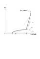
図5は、本実施形態に係る分散電源用発電装置の整流回路10の近似出力特性を示す図である。分散電源用発電装置は、風速に応じて風車1の回転数を調整して、風車1に接続された永久磁石型発電機2から概略の最大出力を取り出すことが求められる。図5に示すように、風車1の最大出力曲線Ptは一般に風車回転数の3乗に比例する。ここで、最大出力曲線Ptは、各風速における出力のピークをつないだものである。
(Output characteristics)
FIG. 5 is a diagram showing an approximate output characteristic of therectifier circuit 10 of the power generation device for distributed power supply according to the present embodiment. The distributed power generation device is required to adjust the rotation speed of the wind turbine 1 according to the wind speed to take out an approximate maximum output from the permanentmagnet type generator 2 connected to the wind turbine 1. As shown in FIG. 5, the maximum output curve Pt of the wind turbine 1 is generally proportional to the cube of the wind turbine rotation speed. Here, the maximum output curve Pt connects the peaks of the output at each wind speed.

本実施形態において、分散電源用発電装置が使用されるシステムで次のような設計(調整)を行う。まず、風車1の定格風車回転数Nrに対して、Nrを超えない(一例としてNrの2/3程度の)風車回転数であるN1を定める。そして、N1において、永久磁石型発電機2の誘起電圧が直流電源5の直流電圧よりも高くなるように調整を行う。N1は第1の整流器37によって、直流電源5の充電が開始される風車回転数である。図5に示すように、風車回転数がN1以上になると、第1の整流器37によって、出力特性P1に従う出力が得られる。 In the present embodiment, the following design (adjustment) is performed in the system in which the power generation device for distributed power supply is used. First, with respect to the rated wind turbine rotation speed Nr of the wind turbine 1, N1 which is a wind turbine rotation speed that does not exceed Nr (for example, about 2/3 of Nr) is determined. Then, in N1, the induced voltage of the permanentmagnet type generator 2 is adjusted to be higher than the DC voltage of the DC power supply 5. N1 is the number of revolutions of the wind turbine in which the DC power supply 5 is started to be charged by thefirst rectifier 37. As shown in FIG. 5, when the rotation speed of the wind turbine becomes N1 or more, the output according to the output characteristic P1 is obtained by thefirst rectifier 37.

ここで、本実施形態に係る分散電源用発電装置の整流回路10は3倍昇圧回路30を備える。3倍昇圧回路30の3倍昇圧整流作用によって、N1の1/3の風車回転数であるN2から、出力特性P2に従う出力が得られる。つまり、N2は、3倍昇圧回路30によって直流電源5の充電が開始される風車回転数である。 Here, therectifier circuit 10 of the distributed power generation device according to the present embodiment includes atriple booster circuit 30. Due to the triple boost rectification action of thetriple boost circuit 30, an output according to the output characteristic P2 can be obtained from N2, which is 1/3 of the windmill rotation speed of N1. That is, N2 is the number of revolutions of the wind turbine in which the DC power supply 5 is started to be charged by thetriple booster circuit 30.

上記のように、本実施形態に係る分散電源用発電装置の整流回路10では、第1の整流器37と3倍昇圧回路30とが並列に接続されている。そのため、本実施形態において、第1の整流器37および3倍昇圧回路30の合計出力が直流電源5に供給される。整流回路10を用いる分散電源用発電装置の出力特性は、図5の太い実線(出力特性P1および出力特性P2の合計)のようになる。整流回路10は、最大出力曲線Ptに近い出力特性(近似出力特性)を有する。 As described above, in therectifier circuit 10 of the distributed power generation device according to the present embodiment, thefirst rectifier 37 and thetriple booster circuit 30 are connected in parallel. Therefore, in the present embodiment, the total output of thefirst rectifier 37 and thetriple booster circuit 30 is supplied to the DC power supply 5. The output characteristics of the distributed power generation device using therectifier circuit 10 are as shown by the thick solid line in FIG. 5 (the sum of the output characteristics P1 and the output characteristics P2). Therectifier circuit 10 has an output characteristic (approximate output characteristic) close to the maximum output curve Pt.

(比較例)
ここで、図6を参照して、比較例の分散電源用発電装置の整流回路10Aを示しながら、本実施形態の分散電源用発電装置の整流回路10の効果について説明する。
(Comparison example)
Here, with reference to FIG. 6, the effect of therectifier circuit 10 of the distributed power generation device of the present embodiment will be described while showing therectifier circuit 10A of the distributed power generation device of the comparative example.

図6は、比較例の分散電源用発電装置の整流回路10Aの図である。整流回路10Aは、第1の整流器37と、第2の整流器34と、第3の整流器35と、第1のコンデンサ31と、第2のコンデンサ32と、を備える。本実施形態に係る分散電源用発電装置の整流回路10と比較すると、整流回路10Aは、第4の整流器36と、第3のコンデンサ33と、を備えない。整流回路10Aは、3倍昇圧回路30ではなく、第2の整流器34と、第3の整流器35と、第2のコンデンサ32と、で構成される2倍昇圧回路30Aを備える。 FIG. 6 is a diagram of therectifier circuit 10A of the distributed power generation device of the comparative example. Therectifier circuit 10A includes afirst rectifier 37, asecond rectifier 34, athird rectifier 35, afirst capacitor 31, and asecond capacitor 32. Compared with therectifier circuit 10 of the distributed power generation device according to the present embodiment, therectifier circuit 10A does not include thefourth rectifier 36 and thethird capacitor 33. Therectifier circuit 10A includes adouble booster circuit 30A composed of asecond rectifier 34, athird rectifier 35, and asecond capacitor 32, instead of thetriple booster circuit 30.

ここで、図5を参照すると、整流回路10Aは、2倍昇圧回路30Aによって、N3から出力特性P3に従う出力を行う。つまり、図5に示されるN3は、2倍昇圧回路30Aによって直流電源5の充電が開始される風車回転数である。N3は、N1の1/2の風車回転数であって、N2よりも大きい。 Here, referring to FIG. 5, the rectifyingcircuit 10A outputs from N3 according to the output characteristic P3 by thedouble booster circuit 30A. That is, N3 shown in FIG. 5 is a wind turbine rotation speed at which charging of the DC power supply 5 is started by thedouble booster circuit 30A. N3 is a wind turbine rotation speed that is 1/2 that of N1 and is larger than N2.

本実施形態に係る分散電源用発電装置の整流回路10は、風車回転数がN2以上であれば電力を出力できる。一方、比較例の整流回路10Aは、風車回転数がN3以上にならないと電力を出力できない。つまり、本実施形態に係る分散電源用発電装置の整流回路10は、3倍昇圧回路30を備える上記の構成によって、永久磁石型発電機2の回転数が低い場合においても電力を出力できる。 Therectifier circuit 10 of the distributed power generation device according to the present embodiment can output electric power if the wind turbine rotation speed is N2 or more. On the other hand, therectifier circuit 10A of the comparative example cannot output electric power unless the wind turbine rotation speed is N3 or higher. That is, the rectifyingcircuit 10 of the distributed power generation device according to the present embodiment can output electric power even when the rotation speed of the permanentmagnet type generator 2 is low due to the above configuration including thetriple booster circuit 30.

また、図5に示される本実施形態に係る分散電源用発電装置の整流回路10の近似出力特性は、風車回転数が低い場合に出力特性P2に従う。そのため、整流回路10の近似出力特性は、比較例の整流回路10A(風車回転数が低い場合に出力特性P3に従う)と比べても、より最大出力曲線Ptに近付いている。つまり、本実施形態に係る分散電源用発電装置の整流回路10は、風車1の回転数に関わらず、最大の出力を取り出すことが可能である。 Further, the approximate output characteristic of therectifier circuit 10 of the distributed power generation device according to the present embodiment shown in FIG. 5 follows the output characteristic P2 when the wind turbine speed is low. Therefore, the approximate output characteristic of therectifier circuit 10 is closer to the maximum output curve Pt than therectifier circuit 10A of the comparative example (following the output characteristic P3 when the wind turbine speed is low). That is, therectifier circuit 10 of the distributed power generation device according to the present embodiment can take out the maximum output regardless of the rotation speed of the wind turbine 1.

また、本実施形態に係る分散電源用発電装置の整流回路10は、例えばPWMコンバータまたはインバータといった制御回路を要することなく風速の変化に対応できる。そのため、分散電源用発電装置の小型化が可能である。 Further, therectifier circuit 10 of the distributed power generation device according to the present embodiment can respond to changes in wind speed without requiring a control circuit such as a PWM converter or an inverter. Therefore, the power generation device for distributed power sources can be miniaturized.

本発明を諸図面および実施形態に基づき説明してきたが、当業者であれば本開示に基づき種々の変形および修正を行うことが容易であることに注意されたい。従って、これらの変形および修正は本発明の範囲に含まれることに留意されたい。 Although the present invention has been described based on the drawings and embodiments, it should be noted that those skilled in the art can easily make various modifications and modifications based on the present disclosure. Therefore, it should be noted that these modifications and modifications are within the scope of the present invention.

1 風車
2 永久磁石型発電機
5 直流電源
10,10A 整流回路
30 3倍昇圧回路
30A 2倍昇圧回路
31 第1のコンデンサ
32 第2のコンデンサ
33 第3のコンデンサ
34 第2の整流器
35 第3の整流器
36 第4の整流器
37 第1の整流器
1Windmill 2 Permanent magnet type generator 5DC power supply 10,10A Rectifier circuit 30Triple booster circuit 30ADouble booster circuit 31First capacitor 32Second capacitor 33Third capacitor 34Second rectifier 35Third Rectifier 36Fourth rectifier 37 First rectifier

Claims (2)

Translated fromJapanese
風車または水車によって駆動される永久磁石型発電機からの交流電力を直流電力に変換して出力する分散電源用発電装置の整流回路であって、
前記永久磁石型発電機に接続される第1の整流器と、
前記永久磁石型発電機に一端が接続される第1のコンデンサと、
第2のコンデンサを介して前記第1のコンデンサの他端と接続される第2の整流器と、
前記第1のコンデンサの他端と接続される第3の整流器と、
第3のコンデンサを介して前記第1のコンデンサの他端と接続される第4の整流器と、を備え、
前記第1の整流器に並列に、前記第2の整流器と、前記第3の整流器と、前記第4の整流器と、が直列に接続されて直流電力を出力する、分散電源用発電装置の整流回路。
A rectifier circuit for a distributed power generator that converts AC power from a permanent magnet generator driven by a windmill or water wheel into DC power and outputs it.
A first rectifier connected to the permanent magnet generator and
The first capacitor, one end of which is connected to the permanent magnet generator,
A second rectifier connected to the other end of the first capacitor via a second capacitor,
A third rectifier connected to the other end of the first capacitor,
A fourth rectifier, which is connected to the other end of the first capacitor via a third capacitor, is provided.
A rectifier circuit of a power generation device for a distributed power source, in which the second rectifier, the third rectifier, and the fourth rectifier are connected in series in parallel with the first rectifier to output DC power. ..
前記第1の整流器、前記第2の整流器、前記第3の整流器および前記第4の整流器は、それぞれ、三組のダイオードを備える三相全波整流回路である、請求項1に記載の分散電源用発電装置の整流回路。 The distributed power supply according to claim 1, wherein the first rectifier, the second rectifier, the third rectifier, and the fourth rectifier are three-phase full-wave rectifier circuits each including three sets of diodes. Rectifier circuit for power generators.
JP2017059830A2017-03-242017-03-24 Rectifier circuit for distributed power generatorActiveJP6775455B2 (en)

Priority Applications (1)

Application NumberPriority DateFiling DateTitle
JP2017059830AJP6775455B2 (en)2017-03-242017-03-24 Rectifier circuit for distributed power generator

Applications Claiming Priority (1)

Application NumberPriority DateFiling DateTitle
JP2017059830AJP6775455B2 (en)2017-03-242017-03-24 Rectifier circuit for distributed power generator

Publications (2)

Publication NumberPublication Date
JP2018164348A JP2018164348A (en)2018-10-18
JP6775455B2true JP6775455B2 (en)2020-10-28

Family

ID=63861193

Family Applications (1)

Application NumberTitlePriority DateFiling Date
JP2017059830AActiveJP6775455B2 (en)2017-03-242017-03-24 Rectifier circuit for distributed power generator

Country Status (1)

CountryLink
JP (1)JP6775455B2 (en)

Also Published As

Publication numberPublication date
JP2018164348A (en)2018-10-18

Similar Documents

PublicationPublication DateTitle
US9385645B2 (en)Methods and systems for electrical DC generation
JP6087531B2 (en) Power converter
CN104348342B (en)Electrical conversion systems and method
US9130448B2 (en)Control arrangement and method for regulating the output voltage of a dc source power converter connected to a multi-source dc system
US20150349687A1 (en)Electric Power Generation and Distribution for Islanded or Weakly-Connected Systems
US10689999B2 (en)Power generation system
US12278571B2 (en)Device for creating a DC voltage bus for a polyphase electrical system, motor vehicle and renewable energy generator comprising such a device
US9859716B2 (en)Hybrid AC and DC distribution system and method of use
JP2011234485A (en)Inverter type generator
JP2009207234A (en)Linkage system of hybrid system
JP2005269843A (en)Parallel operation device
JP5130117B2 (en) Power supply system
JP6156575B2 (en) Power conditioner and control method thereof
JP2017163659A (en)Wind power generation system
JP6775455B2 (en) Rectifier circuit for distributed power generator
JP4641823B2 (en) Rectifier circuit for power generator for distributed power supply
TWI420772B (en)Wind-powered output power regulating circuit
JP4245369B2 (en) Rectifier circuit for power generator for distributed power supply
JP2009136106A (en)Rectifier circuit for wind power generator
JP6453107B2 (en) Power generation system
US11283364B2 (en)Power supply and power system having a step-down circuit and an inverse-conversion circuit
JP5130116B2 (en) Power supply system
JP5300427B2 (en) Rectifier circuit for power generator for distributed power supply
KR101566802B1 (en)Charging system for charging DC link
JP2014011835A (en)Rectifier circuit for power generation system for distributed power sources

Legal Events

DateCodeTitleDescription
A621Written request for application examination

Free format text:JAPANESE INTERMEDIATE CODE: A621

Effective date:20191212

A977Report on retrieval

Free format text:JAPANESE INTERMEDIATE CODE: A971007

Effective date:20200917

TRDDDecision of grant or rejection written
A01Written decision to grant a patent or to grant a registration (utility model)

Free format text:JAPANESE INTERMEDIATE CODE: A01

Effective date:20200929

A61First payment of annual fees (during grant procedure)

Free format text:JAPANESE INTERMEDIATE CODE: A61

Effective date:20201006

R150Certificate of patent or registration of utility model

Ref document number:6775455

Country of ref document:JP

Free format text:JAPANESE INTERMEDIATE CODE: R150


[8]ページ先頭

©2009-2025 Movatter.jp