JP6774904B2 - Weighing cap - Google Patents
Weighing capDownload PDFInfo
- Publication number
- JP6774904B2 JP6774904B2JP2017072411AJP2017072411AJP6774904B2JP 6774904 B2JP6774904 B2JP 6774904B2JP 2017072411 AJP2017072411 AJP 2017072411AJP 2017072411 AJP2017072411 AJP 2017072411AJP 6774904 B2JP6774904 B2JP 6774904B2
- Authority
- JP
- Japan
- Prior art keywords
- measuring
- cap
- cylinder portion
- introduction hole
- container body
- Prior art date
- Legal status (The legal status is an assumption and is not a legal conclusion. Google has not performed a legal analysis and makes no representation as to the accuracy of the status listed.)
- Active
Links
- 238000005303weighingMethods0.000titledescription26
- 230000002093peripheral effectEffects0.000claimsdescription43
- 238000005192partitionMethods0.000claimsdescription16
- 238000002347injectionMethods0.000description7
- 239000007924injectionSubstances0.000description7
- 239000000243solutionSubstances0.000description5
- 230000008878couplingEffects0.000description4
- 238000010168coupling processMethods0.000description4
- 238000005859coupling reactionMethods0.000description4
- -1polypropylenePolymers0.000description4
- 229920003002synthetic resinPolymers0.000description4
- 239000000057synthetic resinSubstances0.000description4
- 230000000903blocking effectEffects0.000description3
- 239000000463materialSubstances0.000description3
- 238000005259measurementMethods0.000description3
- 238000011084recoveryMethods0.000description3
- 239000004698PolyethyleneSubstances0.000description2
- 239000004743PolypropyleneSubstances0.000description2
- 239000000470constituentSubstances0.000description2
- 239000007788liquidSubstances0.000description2
- 238000000034methodMethods0.000description2
- 238000012986modificationMethods0.000description2
- 230000004048modificationEffects0.000description2
- 229920000573polyethylenePolymers0.000description2
- 229920001155polypropylenePolymers0.000description2
- 230000000717retained effectEffects0.000description2
- 239000004909MoisturizerSubstances0.000description1
- 239000000730antalgic agentSubstances0.000description1
- 239000002260anti-inflammatory agentSubstances0.000description1
- 229940121363anti-inflammatory agentDrugs0.000description1
- 125000003118aryl groupChemical group0.000description1
- 230000003796beautyEffects0.000description1
- 238000007796conventional methodMethods0.000description1
- 239000002537cosmeticSubstances0.000description1
- 239000002781deodorant agentSubstances0.000description1
- 239000003599detergentSubstances0.000description1
- 239000003814drugSubstances0.000description1
- 229940079593drugDrugs0.000description1
- 230000000694effectsEffects0.000description1
- 230000001333moisturizerEffects0.000description1
- 230000000149penetrating effectEffects0.000description1
- 239000000126substanceSubstances0.000description1
Images


Landscapes
- Closures For Containers (AREA)
Description
Translated fromJapanese本発明は、計量キャップに関する。 The present invention relates to a measuring cap.
計量キャップとして、例えば下記特許文献1に示されるように、内容物が収容される容器体の口部に装着される有頂筒状の装着筒と、装着筒の内側に固定された計量筒と、を有する計量キャップが知られている。計量筒は、装着筒の頂壁から容器体の内側に向かって延び、その内周面に計量用目盛が形成されている。 As the measuring cap, for example, as shown in
上記従来の計量キャップを使用する場合には、容器体から計量キャップを取り外した後、例えば容器体を傾け、口部を通じて計量筒内に内容物を注出する。この際、計量筒に計量用目盛が形成されているので内容物を計量しながら計量筒に注出できる。これにより、計量された量の内容物を使用することが可能となる。 When the conventional measuring cap is used, after removing the measuring cap from the container body, for example, the container body is tilted and the contents are poured into the measuring cylinder through the mouth. At this time, since a measuring scale is formed on the measuring cylinder, the contents can be weighed and poured into the measuring cylinder. This makes it possible to use a measured amount of content.
しかしながら上記従来の計量キャップでは、計量用目盛に内容物を合わせる必要があるので、計量筒への内容物の注出を慎重に行わざるを得なく、計量時の操作性に改善の余地があった。例えば計量筒に注出した内容物と計量用目盛との比較をした結果、計量用目盛に内容物が達していない場合には、内容物の注出を繰り返し行って、計量用目盛に内容物が達するように微調整を行う必要がある。よって、手間がかかり易く操作性が悪い。
さらに、従来の計量キャップでは、計量時に内容物が計量用目盛を容易に超えてしまい易いので、内容物の計量を再現性良く安定して行うことが難しい。特に、内容物が計量用目盛を超えてしまった場合には、計量のやり直しが必要とされる場合があり、この点においても計量時の操作性に改善の余地がある。However, in the above-mentioned conventional weighing cap, since it is necessary to align the contents with the weighing scale, the contents must be carefully poured into the measuring cylinder, and there is room for improvement in operability during weighing. It was. For example, as a result of comparing the contents poured out to the measuring cylinder with the measuring scale, if the contents do not reach the measuring scale, the contents are repeatedly poured out to the measuring scale. It is necessary to make fine adjustments so that Therefore, it is easy to take time and effort, and the operability is poor.
Further, with the conventional weighing cap, the contents easily exceed the weighing scale at the time of weighing, so that it is difficult to weigh the contents stably with good reproducibility. In particular, when the content exceeds the weighing scale, it may be necessary to redo the weighing, and in this respect as well, there is room for improvement in operability during weighing.
本発明は、このような事情に鑑みてなされたものであって、その目的は、簡便な操作で内容物の計量を適切に行うことができると共に、計量を再現性良く安定して行うことができる計量キャップを提供することである。 The present invention has been made in view of such circumstances, and an object of the present invention is to be able to appropriately measure the contents by a simple operation and to perform the measurement stably with good reproducibility. It is to provide a weighing cap that can be used.
(1)本発明に係る計量キャップは、内容物が収容される容器本体の口部に離脱可能に装着される有頂筒状の計量筒部と、前記計量筒部に装着されると共に、前記計量筒部の頂壁部よりもキャップ軸方向に沿う前記容器本体の外側に配置されたキャップ頂壁部を有する有頂筒状の外キャップと、を備え、前記計量筒部は、前記頂壁部から前記容器本体の内側に向けて延びると共に、その内側が前記キャップ頂壁部側に向けて開口した有底筒状の区画筒部と、前記区画筒部を径方向外側から囲むと共に、前記頂壁部から前記区画筒部よりも前記容器本体の内側に向けて延び、前記区画筒部との間に前記容器本体の内側に向けて開口した環状の計量室を画成させる注出筒部と、を備え、前記計量筒部と前記外キャップとの間には、前記区画筒部の内側に連通する回収室が画成され、前記区画筒部には、前記計量室内と前記回収室内とを連通すると共に、前記計量室内の容積のうち、予め決められた第1設定容積を超える内容物の余剰分を前記計量室側から前記回収室側に導く導入孔が形成されている。(1) The measuring cap according to the present invention has a climaxed tubular measuring cylinder portion that is detachably attached to the mouth of the container body in which the contents are housed, and the measuring cylinder portion that is attached to the measuring cylinder portion and described above. A ridged tubular outer cap having a cap top wall portion arranged outside the container body along the cap axial direction with respect to the top wall portion of the measuring cylinder portion is provided, and the measuring cylinder portion is provided with the top wall portion. A bottomed tubular compartment tube portion that extends from the portion toward the inside of the container body and the inside thereof opens toward the top wall portion of the cap, and the compartment cylinder portion that surrounds the compartment cylinder portion from the outside in the radial direction. A pouring cylinder portion that extends from the top wall portion toward the inside of the container body from the compartment cylinder portion and defines an annular measuring chamber that opens toward the inside of the container body with the compartment cylinder portion. And, a collection chamber communicating with the inside of the compartment cylinder portion is defined between the measuring cylinder portion and the outer cap, and the measuring chamber and the collection chamber are provided in the compartment cylinder portion. In addition to communicating with each other, an introduction hole is formed to guide the surplus of the contents exceeding the predetermined first set volume among the volumes of the measuring chamber from the measuring chamber side to the collecting chamber side.
本発明に係る計量キャップによれば、容器本体の口部から取り外した後、外キャップが下向きとなるように上下反転させることで、計量室が上方に向けて開口した状態となると共に、注出筒部の開口端部及び区画筒部の底壁が上方を向いた状態となる。これにより、容器本体の口部を通じて、容器本体内の内容物を計量キャップ内に注出することで、内容物を計量室内に徐々に溜めることができる。
このとき、区画筒部に導入孔が形成されているので、第1設定容積を超える量の内容物が容器本体側から計量室内に注出されたとしても、第1設定容積を超えた分の内容物、すなわち内容物の余剰分を、導入孔を通じて計量室側から回収室側に導いて逃がすことができる。従って、計量室内に決まった量の内容物、すなわち第1設定容積に対応した量の内容物を溜めることができ、正確な計量を行うことができる。
また、容器本体側から計量室内にこれ以上内容物を注出したとしても、計量室内に溜まった内容物の量は変化せずに、導入孔を通じて回収室側に内容物が流れるだけであるので、使用者は例えば内容物の流れの変化を視認することで、計量が終了したことを容易に把握することができる。According to the measuring cap according to the present invention, after removing from the mouth of the container body, the outer cap is turned upside down so as to face downward, so that the measuring chamber is opened upward and the injection is performed. The open end of the cylinder and the bottom wall of the compartment cylinder are in a state of facing upward. As a result, the contents in the container body can be gradually accumulated in the measuring chamber by pouring the contents in the container body into the measuring cap through the mouth of the container body.
At this time, since the introduction hole is formed in the compartment cylinder portion, even if the content exceeding the first set volume is poured into the measuring chamber from the container body side, the amount exceeding the first set volume is formed. The contents, that is, the surplus of the contents, can be guided from the measuring chamber side to the collection chamber side through the introduction hole and escaped. Therefore, a fixed amount of contents, that is, an amount of contents corresponding to the first set volume can be stored in the measuring chamber, and accurate weighing can be performed.
Further, even if the contents are further poured into the measuring chamber from the container body side, the amount of the contents accumulated in the measuring chamber does not change, and the contents only flow to the collection chamber side through the introduction hole. , The user can easily grasp that the weighing is completed, for example, by visually recognizing the change in the flow of the contents.
特に、計量用目盛を利用していた従来とは異なり、容器本体側から計量キャップ側に内容物を単純に注出するだけで、余分な内容物を回収室側に逃がしながら計量室内に決まった量の内容物を溜めることができるので、簡便な操作で内容物の計量を適切に行うことができると共に、計量を再現性良く安定して行うことができる。
なお、計量室内に溜まった内容物を例えば外部に注出した後、計量キャップを容器本体の口部に装着して元の状態に戻すことで、回収室内に溜まった内容物を、導入孔及び注出筒部の内側を通じて容器本体内に戻すことができる。In particular, unlike the conventional method that used a weighing scale, the contents were simply poured out from the container body side to the measuring cap side, and the excess contents were released to the collection chamber side while being determined in the measuring chamber. Since a large amount of contents can be stored, the contents can be appropriately weighed by a simple operation, and the weighing can be performed stably with good reproducibility.
After pouring the contents accumulated in the measuring chamber to the outside, for example, by attaching the measuring cap to the mouth of the container body and returning it to the original state, the contents accumulated in the collection chamber can be introduced into the introduction hole and It can be returned to the inside of the container body through the inside of the dispensing cylinder.
(2)前記注出筒部の開口端部には、前記容器本体の内側に向けてさらに突出する注出片が形成され、前記導入孔は、前記区画筒部のうち、前記注出片とはキャップ軸を挟んで径方向の反対側に位置する部分に形成されても良い。(2) At the open end of the dispensing cylinder portion, a dispensing piece that further protrudes toward the inside of the container body is formed, and the introduction hole is formed with the dispensing piece of the compartment cylinder portion. May be formed in a portion located on the opposite side of the cap shaft in the radial direction.
この場合には、内容物の計量後、例えば注出片を下向きにした状態で計量キャップを傾けることで、注出片を利用して計量室内に溜まった内容物を外部に注出することができ、計量された量の内容物を使用することができる。
導入孔は、注出片とはキャップ軸を挟んで径方向の反対側に位置しているので、上述した内容物の注出時、導入孔は上方を向いた状態となる。従って、回収室内に溜まった内容物は、計量キャップの傾きに伴って区画筒部の底壁側に移動するが、上方を向いた導入孔に到達し難い。そのため、導入孔を通じて区画筒部の外側に内容物が流出してしまうことを抑制でき、区画筒部内に内容物を留まらせることができる。これにより、回収室内に溜まった内容物を混入させることなく、計量室内に溜まった内容物だけを外部に注出させることができ、より正確に計量された量の内容物を使用することができる。In this case, after weighing the contents, for example, by tilting the measuring cap with the dispensed piece facing downward, the contents accumulated in the measuring chamber can be dispensed to the outside using the dispensed piece. Can and weighed quantities of content can be used.
Since the introduction hole is located on the opposite side of the cap shaft in the radial direction from the injection piece, the introduction hole is in a state of facing upward when the above-mentioned contents are injected. Therefore, the contents accumulated in the collection chamber move toward the bottom wall side of the partition cylinder portion as the measuring cap tilts, but it is difficult to reach the introduction hole facing upward. Therefore, it is possible to prevent the contents from flowing out to the outside of the compartment cylinder portion through the introduction hole, and the contents can be retained in the compartment cylinder portion. As a result, it is possible to discharge only the contents accumulated in the measuring chamber to the outside without mixing the contents accumulated in the collection chamber, and it is possible to use the contents in a more accurately measured amount. ..
(3)前記導入孔は、前記区画筒部における周壁にキャップ軸方向に沿って縦長に形成され、前記キャップ頂壁部には、前記容器本体の内側に向けて延びると共に、前記導入孔の一部を前記区画筒部の内側から閉塞可能な閉塞片が形成され、前記外キャップは、前記計量筒部に対してキャップ軸回りに相対回転可能に装着されると共に、回転に伴って前記閉塞片を、前記導入孔の一部を閉塞する閉塞位置と前記導入孔を開放する開放位置とに切り換え可能とされ、前記導入孔は、前記閉塞片が前記閉塞位置に位置しているときに、前記計量室内の容積のうち、前記第1設定容積よりも容積が大きい第2設定容積を超える内容物の余剰分を前記計量室側から前記回収室側に導いても良い。(3) The introduction hole is formed vertically on the peripheral wall of the compartment cylinder portion along the cap axial direction, extends toward the inside of the container body, and is one of the introduction holes. An obstruction piece capable of closing the portion from the inside of the compartment cylinder portion is formed, and the outer cap is attached to the measuring cylinder portion so as to be relatively rotatable around the cap axis, and the obstruction piece is attached with rotation. Can be switched between a closed position that closes a part of the introduction hole and an open position that opens the introduction hole, and the introduction hole is said when the closed piece is located at the closed position. Of the volume of the measuring chamber, the surplus content exceeding the second set volume, which is larger than the first set volume, may be guided from the measuring chamber side to the collecting chamber side.
この場合には、例えば、外キャップを回転操作して閉塞片を開放位置に位置させた場合には、導入孔を開放できるので、先に述べたように第1設定容積を超えた分の内容物を、導入孔を通じて回収室側に逃がしながら、計量室内に決まった量(第1設定容積に対応した量)の内容物を溜めることができる。
これに対して、外キャップを回転操作して閉塞片を閉塞位置に位置させた場合には、導入孔の一部が閉塞片によって閉塞されるので、閉塞された分だけ計量室内に内容物を溜めることができ、計量室内に内容物をさらに大量に溜めることができる。そして、計量室内に、第2設定容積に対応した量の内容物が溜まった後、第2設定容積を超えた分の内容物(内容物の余剰分)を、閉塞片を乗り越えるように導入孔を通じて回収室側に逃がすことができる。これにより、第1設定容積よりも容積が大きい第2設定容積に対応した量の内容物を計量室内に溜めることができる。
以上のことから、外キャップを回転操作するだけの簡便な操作で、計量する内容物の量を変更することができ、より使い易い計量キャップとすることができる。In this case, for example, when the outer cap is rotated to position the closed piece in the open position, the introduction hole can be opened, so that the content exceeding the first set volume is described above. It is possible to store a fixed amount of contents (amount corresponding to the first set volume) in the measuring chamber while allowing the material to escape to the collection chamber side through the introduction hole.
On the other hand, when the outer cap is rotated to position the closed piece at the closed position, a part of the introduction hole is closed by the closed piece, so that the contents are placed in the measuring chamber by the amount of the closed piece. It can be stored, and a larger amount of contents can be stored in the measuring chamber. Then, after the amount of contents corresponding to the second set volume is accumulated in the measuring chamber, the contents exceeding the second set volume (surplus contents) are introduced through the introduction holes so as to get over the obstructed piece. It can be escaped to the collection room side through. As a result, an amount of contents corresponding to the second set volume, which is larger than the first set volume, can be stored in the measuring chamber.
From the above, the amount of contents to be weighed can be changed by a simple operation of simply rotating the outer cap, and the weighing cap can be made easier to use.
(4)前記導入孔は、前記周壁から前記区画筒部における底壁に亘って形成されても良い。(4) The introduction hole may be formed from the peripheral wall to the bottom wall in the section cylinder portion.
この場合には、内容物の計量時、上方を向いた状態となる区画筒部の底壁にまで導入孔が形成されているので、内容物が計量室側から回収室側に向けて流れる様子を確認し易い。従って、内容物の計量が終了したことを、容易且つ確実に把握し易い。 In this case, since the introduction hole is formed up to the bottom wall of the compartment cylinder portion that faces upward when the contents are weighed, the contents flow from the measuring chamber side to the collection chamber side. Easy to check. Therefore, it is easy and surely to grasp that the weighing of the contents is completed.
本発明に係る計量キャップによれば、簡便な操作で内容物の計量を適切に行うことができると共に、計量を再現性良く安定して行うことができる。 According to the measuring cap according to the present invention, the contents can be appropriately weighed by a simple operation, and the weighing can be performed stably with good reproducibility.
以下、本発明に係る計量キャップの実施形態について図面を参照して説明する。
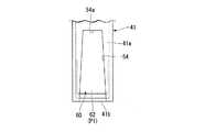
図1に示すように、本実施形態の計量キャップ1は、内容物W(図3参照)が収容される容器本体10の口部11に離脱可能に装着され、口部11を開閉する有頂筒状の計量筒部2と、計量筒部2に装着された有頂筒状の外キャップ3と、を備えている。Hereinafter, embodiments of the measuring cap according to the present invention will be described with reference to the drawings.
As shown in FIG. 1, the measuring
図1において、容器本体10の口部11、計量筒部2及び外キャップ3は、それぞれの中心軸線が共通軸上に配置されている。以下、この共通軸をキャップ軸Oといい、キャップ軸O方向に沿う容器本体10の外側、すなわち外キャップ3側を上方、その反対側である容器本体10側を下方という。また、キャップ軸O方向から見た平面視でキャップ軸Oに直交する方向を径方向といい、キャップ軸O回りに周回する方向を周方向という。 In FIG. 1, the central axes of the
なお、内容物Wとしては特に限定されるものではないが、例えば化粧液、保湿液、美容液、洗剤液、柔軟剤液、薬液(傷薬、消炎剤や鎮痛剤等)、消臭液や揮散剤を含む芳香液等の各種液体が挙げられる。 The content W is not particularly limited, but for example, a cosmetic solution, a moisturizer, a beauty essence, a detergent solution, a softener solution, a chemical solution (scratch drug, an anti-inflammatory agent, an analgesic agent, etc.), a deodorant solution, etc. Examples thereof include various liquids such as an aromatic liquid containing a volatilizer.
(容器本体の口部)
はじめに、容器本体10の口部11について説明する。
容器本体10の口部11は、容器本体10に形成された第1口部12と、第1口部12に装着された有底筒状の中栓部材14における第2口部13と、で構成されている。(Mouth of the container body)
First, the
The
第1口部12の外周面には、第1ねじ部15が形成されていると共に、第1ねじ部15よりも下方に位置する部分に、径方向外側に向けて突出すると共に上下に延びる回り止めリブ16が周方向に間隔をあけて複数形成されている。 A
中栓部材14は、第1口部12を径方向外側から囲む外筒部20と、外筒部20の上端部から径方向内側に向けて延び、第1口部12の上端開口縁上に配置された環状のフランジ部21と、フランジ部21から上方に向けて延びた上記第2口部13と、フランジ部21の内周縁部から下方に向けて延びた内筒部22と、内筒部22の下端部から径方向内側に向けて延びた底壁部23と、を備え、キャップ軸Oと同軸に配置されている。 The
外筒部20の内周面には、第1ねじ部15に螺着された第2ねじ部24が形成されている。これにより、中栓部材14の全体は、第1口部12に対してねじ結合によって装着されている。ただし、第1口部12に対する中栓部材14の装着方法は、ねじ結合に限定されるものではなく、例えばアンダーカット嵌合により装着しても構わない。 A
外筒部20の下端部側の内周面には、周方向を向く壁面を有するリブ25が形成されている。リブ25は、中栓部材14が第1口部12に装着される際、第1口部12の回り止めリブ16に対して周方向から係合可能とされている。これにより、中栓部材14はリブ25が回り止めリブ16に周方向から係合することで、第1口部12に対して開封されないようにしている。 A
第2口部13は、第1口部12と略同径に形成され、その外周面には第3ねじ部26が形成されている。
内筒部22は、第1口部12の内径よりも外径が小さく形成され、第1口部12との間に若干の隙間をあけた状態で第1口部12の内側に配設されている。なお、内筒部22と第1口部12との間には、フランジ部21に一体に形成されたシール筒部27が配置されている。シール筒部27は、フランジ部21から下方に向けて延び、第1口部12における上端部の内側に密に嵌合している。The
The
底壁部23は、キャップ軸Oに垂直な面に対して傾斜するように形成されていると共に、内容物Wを注出するための注出ノズル30が一体に形成されている。
注出ノズル30は、底壁部23から上方に向けて突設され、その内側は容器本体10の内側に連通している。図示の例では、注出ノズル30は、その中心軸がキャップ軸Oに対して僅かに偏心した状態で形成されている。ただし、注出ノズル30は、その中心軸がキャップ軸Oと同軸或いはキャップ軸Oとほぼ一致するように形成されていても構わない。The
The
なお本実施形態では、径方向のうちキャップ軸Oから注出ノズル30の中心軸に向かう方向を前方といい、その反対側を後方という。 In the present embodiment, the radial direction from the cap shaft O toward the central axis of the
注出ノズル30は、第2口部13よりも上方に突出していると共に、その上端部側が上方に向かうにしたがって前方に向けて徐々に先細るように形成されている。これにより、注出ノズル30の上端部は前方側に位置している。なお、この前方に位置する注出ノズル30の上端部が注出口31とされている。そのため、注出口31を下向きにした状態で容器本体10を傾けることで、注出口31を通じて容器本体10内の内容物Wを注出することが可能とされている。 The dispensing
注出ノズル30のうち後方側に位置する部分には、注出口31から注出ノズル30と底壁部23との接続部分に至る全長に亘ってスリット32が形成されている。これにより、本実施形態の注出ノズル30は、横断面視C形状に形成されている。ただし、注出ノズル30の形状は、横断面視C形状に限定されるものではなく、例えば横断面視円形状或いは楕円形状に形成されても構わない。 A
(計量キャップ)
次に、計量キャップ1について詳細に説明する。
計量筒部2は、容器本体10の口部11のうち、中栓部材14における第2口部13に対して離脱可能に装着されている。
なお、計量筒部2の材質は、特に限定されるものではないが、例えばポリプロピレンやポリエチレン等の合成樹脂が好ましく、さらには透明或いは半透明な合成樹脂とすることが好ましい。(Measuring cap)
Next, the measuring
The measuring
The material of the measuring
計量筒部2は、注出ノズル30よりも上方に配置された頂壁部40と、頂壁部40の中央部分から下方に向けて延びると共に、その内側が上方に向けて開口した有底筒状の区画筒部41と、頂壁部40の外周縁部から下方に向けて延び、区画筒部41を径方向外側から囲む注出筒部42と、第2口部13を径方向外側から囲む装着筒部43と、装着筒部43の上端部と注出筒部42とを連結する環状の連結壁部44と、を備えている。 The measuring
頂壁部40は、外径が中栓部材14の内筒部22の内径よりも僅かに小さい平面視円形状に形成されている。
区画筒部41は、頂壁部40から下方に向けて延びた周壁41a、及び周壁41aの下端開口部を塞ぐ底壁41bを備え、注出ノズル30の内側に上方から挿入された状態でキャップ軸Oと同軸に配置されている。図示の例では、区画筒部41は、底壁41bが中栓部材14のフランジ部21よりも僅かに下方に位置するように、注出ノズル30内に挿入されている。The
The
注出筒部42は、区画筒部41及び注出ノズル30を径方向外側から囲むと共に、区画筒部41よりも下方に向けて延びるように形成されている。図示の例では、注出筒部42は、中栓部材14の内筒部22と注出ノズル30との間に配置され、その内側は下方に向けて開口している。
注出筒部42と区画筒部41の周壁41aと頂壁部40との間に画成された空間は、下方に向けて開口した環状の計量室45とされている。The dispensing
The space defined between the dispensing
注出筒部42の下端部(開口端部)のうち前方側に位置する部分には、さらに下方に向けて突出する注出片46が形成されている。これにより、計量キャップ1を取り外した後、注出片46を下向きにした状態で計量キャップ1を傾けることで、注出片46を通じて計量室45内に溜まった内容物Wを外部に注出することが可能とされている。
なお、注出片46における下端部には、前方に向けて僅かに突出すると共に、前方に向かうにしたがって厚みが漸次薄くなる先鋭化したリップ部46aが形成されている。A dispensing
A sharpened
装着筒部43の内周面には、第2口部13に形成された第3ねじ部26に螺着される第4ねじ部47が形成されている。これにより、計量キャップ1の全体は、第2口部13に対してねじ結合によって装着されている。ただし、第2口部13に対する計量キャップ1の装着方法は、ねじ結合に限定されるものではなく、例えばアンダーカット嵌合により装着しても構わない。 A
連結壁部44は、装着筒部43の上端部から径方向内側に向けて延び、第2口部13の上端開口端上に配置される環状の第1連結壁部44aと、第1連結壁部44aの内周縁部から上方に向けて延びた筒状の第2連結壁部44bと、第2連結壁部44bの上端部から径方向内側に向けて延び、注出筒部42に連結された環状の第3連結壁部44cと、を備えている。
ただし、連結壁部44の形状は、この場合に限定されるものではなく、例えば第1連結壁部44aの内周縁部が注出筒部42に対して連結するように構成されても構わない。The connecting
However, the shape of the connecting
第1連結壁部44aには、下方に向けて延び、第2口部13における上端部の内側に密に嵌合するシール筒部48が形成されている。また、頂壁部40の外周縁部には、上方に向けて延びたガイド筒部49が形成されている。図示の例では、ガイド筒部49の外径は、注出筒部42の外径よりも僅かに小さく形成されている。
なお、ガイド筒部49は必須なものではなく、具備しなくても構わない。The first connecting
The
外キャップ3は、計量筒部2に対してキャップ軸O回りに相対回転可能に装着されている。なお、外キャップ3の材質は、特に限定されるものではないが、例えば計量筒部2と同様に、ポリプロピレンやポリエチレン等の合成樹脂が好ましく、さらには透明或いは半透明な合成樹脂とすることが好ましい。 The
外キャップ3は、中栓部材14の頂壁部40よりも上方に配置されたキャップ頂壁部50と、キャップ頂壁部50の外周縁部から下方に向けて延び、計量筒部2のガイド筒部49を径方向外側から囲む第1キャップ周壁部51と、第1キャップ周壁部51の下端部から下方に向けてさらに延び、計量筒部2における注出筒部42のうち、第3連結壁部44cよりも上方に位置する部分を径方向外側から囲む第2キャップ周壁部52と、を備えている。 The
第1キャップ周壁部51は、ガイド筒部49の外周面に対してキャップ軸O回りに回転可能に接している。これにより、外キャップ3の全体を、ガイド筒部49で安定にガイドしながら回転操作することが可能とされている。
第2キャップ周壁部52は、注出筒部42に対して上方への抜け止めがされた状態で、キャップ軸O回りに回転可能に連結されている。図示の例では、第2キャップ周壁部52は、注出筒部42に全周に亘って形成された環状突起42aに対してアンダーカット嵌合されることで、キャップ軸O回りに回転可能に連結されている。The first cap
The second cap
上述のように構成された外キャップ3と計量筒部2との間には、余分な内容物Wを回収するための回収室53が画成されている。回収室53は、頂壁部40とキャップ頂壁部50とガイド筒部49との間に画成され、区画筒部41の内側に連通している。 A
そして区画筒部41には、計量室45内と回収室53内とを連通すると共に、計量室45内の容積のうち、予め決められた第1設定容積V1を超える内容物Wの余剰分を計量室45側から回収室53側に導く導入孔54が形成されている。 Then, the
導入孔54は、区画筒部41のうち注出片46とはキャップ軸Oを挟んで径方向の反対側に位置する部分に形成されている。
具体的には、図1及び図2に示すように、導入孔54は区画筒部41の周壁41aのうち後方側に位置する部分にキャップ軸Oに沿って縦長に形成されている。図示の例では、導入孔54は周壁41aのうち第3連結壁部44cと同等の高さに位置する部分から、底壁41bに亘って縦長に形成され、下方に開口している。The
Specifically, as shown in FIGS. 1 and 2, the
なお、導入孔54は、該導入孔54の開口縁のうち上方に位置する上側開口縁54aから下方に向かうにしたがって周方向に沿った周幅が漸次大きくなるように側面視台形状に形成されている。ただし、導入孔54の形状は、この場合に限定されるものではなく、例えば縦長のスリット状に形成されていても構わない。 The
そして、区画筒部41の周壁41aのうち頂壁部40から導入孔54の上側開口縁54aまでに至る部分と、頂壁部40と、注出筒部42と、で画成される環状空間の容積が上記第1設定容積V1とされる。これにより、図3に示すように、計量キャップ1を取り外したときに、第1設定容積V1に対応した量の内容物Wを計量室45内に溜めることが可能とされている。そして、導入孔54は、第1設定容積V1を超える内容物Wの余剰分を回収室53側に逃がすことが可能とされている。 An annular space defined by a portion of the
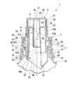
図1に示すように、外キャップ3にはキャップ頂壁部50から下方に向けて延び、区画筒部41の内側に挿入された閉塞部材60が形成されている。閉塞部材60は、円筒状に形成された閉塞筒部61と、閉塞筒部61の下端部からさらに下方に向けて延びた閉塞片62と、を備え、キャップ軸Oと同軸に配置されている。 As shown in FIG. 1, the
閉塞筒部61は、キャップ頂壁部50における中央部分から下方に向けて延び、区画筒部41における周壁41aの内側に接している。なお閉塞筒部61は、区画筒部41に対してキャップ軸O回りに相対回転可能に接している。閉塞筒部61の下端部は、導入孔54における上側開口縁54aと同等の高さ位置に位置しており、導入孔54を区画筒部41の内側から閉塞しないように形成されている。 The
閉塞筒部61のうち、主に頂壁部40よりも上方に位置する部分には、閉塞筒部61を径方向に貫通する貫通孔63が周方向に間隔をあけて複数形成されている。
貫通孔63は、閉塞筒部61のうち主に頂壁部40よりも上方に位置する部分に、その全長に亘って縦長のスリット状に形成されている。これにより、閉塞筒部61の内側は貫通孔63を通じて回収室53内に連通している。A plurality of through
The through
閉塞片62は、横断面視円弧状に形成され、その下端部が区画筒部41の底壁41bの近傍に達する程度、下方に向けて延びている。図2に示すように、閉塞片62の周方向に沿った周幅は、導入孔54における最大の周幅よりも僅かに大きい。これにより、閉塞片62は導入孔54の一部を、区画筒部41の内側から閉塞することが可能とされている。 The
上述のように構成された閉塞部材60は、外キャップ3のキャップ軸O回りの回転操作に伴って回転する。そのため、閉塞片62は、外キャップ3の回転に伴って、図1に示すように導入孔54の一部を閉塞する閉塞位置P1と、図4に示すように導入孔54を開放する開放位置P2と、の間を移動可能とされている。つまり、外キャップ3を回転操作することで、閉塞片62の位置を開放位置P2と閉塞位置P1とに切り換えることが可能とされている。 The closing
図4に示すように、閉塞片62が閉塞位置P1に位置している場合には、閉塞片62と頂壁部40と注出筒部42とで画成される環状空間の容積が、上記第1設定容積V1よりも容積が大きい第2設定容積V2とされる。
これにより、図5に示すように、計量キャップ1を取り外したときに、第2設定容積V2に対応した量の内容物Wを計量室45内に溜めることが可能とされている。そして、この場合、導入孔54は第2設定容積V2を超える内容物Wの余剰分を回収室53側に逃がすことが可能とされている。As shown in FIG. 4, when the
As a result, as shown in FIG. 5, when the measuring
なお、計量筒部2の外周面(例えば連結壁部44の外周面)と、外キャップ3の外周面(例えば第2キャップ周壁部52の外周面)とに、計量筒部2に対する外キャップ3の周方向位置(回転位置)を表示するための表示部を設けても良い。表示部としては、特に限定されるものではないが、例えば刻印や印刷等によって表示された印や目盛等が挙げられる。この場合には、例えば計量筒部2の外周面側に第1の表示部を設け、外キャップ3の外周面側に第2の表示部を設ければ良い。このようにすることで、第1の表示部と第2の表示部との相対位置関係によって、計量筒部2に対する外キャップ3の回転位置を容易に把握でき、閉塞片62の位置を開放位置P2と閉塞位置P1とに容易且つ正確に切り換えることができる。 The outer peripheral surface of the measuring cylinder portion 2 (for example, the outer peripheral surface of the connecting wall portion 44) and the outer peripheral surface of the outer cap 3 (for example, the outer peripheral surface of the second cap peripheral wall portion 52) are provided with the
(計量キャップの使用)
次に、上述のように構成された計量キャップ1を利用して内容物Wを計量する場合について説明する。
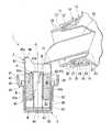
この場合には、計量キャップ1を容器本体10の口部11から取り外した後、図6に示すように外キャップ3が下向きとなるように計量キャップ1を上下反転させた状態で配置する。なお、図6に示す状態では閉塞片62が閉塞位置P1に位置している。(Use of weighing cap)
Next, a case where the content W is weighed by using the measuring
In this case, after the measuring
計量キャップ1の上下反転によって、キャップ軸O方向に沿った外キャップ3側が下方を向き、計量筒部2側が上方を向く。そのため、計量室45が上方に向けて開口した状態となると共に、注出筒部42の下端部及び区画筒部41の底壁41bが上方を向いた状態となる。
次いで、注出口31を下向きにした状態で容器本体10を傾け、注出口31を通じて容器本体10内の内容物Wを計量キャップ1内に注出する。これにより、内容物Wを計量室45内に徐々に溜めることができる。By turning the measuring
Next, the
このとき、閉塞片62が閉塞位置P1に位置しているので、閉塞片62が導入孔54の一部を区画筒部41の内側から閉塞している。そのため、導入孔54が閉塞されている分だけ計量室45内に内容物Wを溜めることができ、図6に示すように計量室45内に、第2設定容積V2に対応した量の内容物Wを溜めることができる。
そして、これ以降、第2設定容積V2を超えた分の内容物W、すなわち、内容物Wの余剰分については、閉塞片62を乗り越えるように導入孔54を通じて回収室53側に導いて逃がすことができる。At this time, since the
After that, the content W exceeding the second set volume V2, that is, the surplus content W, is guided to the
従って、計量室45内に決まった量の内容物W、すなわち第2設定容積V2に対応した量の内容物Wを溜めることができ、正確な計量を行うことができる。また、容器本体10側から計量室45内にこれ以上内容物Wを注出したとしても、計量室45内に溜まった内容物Wの量は変化せずに、導入孔54を通じて回収室53側に内容物Wが流れるだけであるので、使用者は例えば内容物Wの流れの変化を視認することで、計量が終了したことを容易に把握することができる。 Therefore, a fixed amount of contents W, that is, an amount of contents W corresponding to the second set volume V2 can be stored in the measuring
なお、内容物Wの計量時、上方を向いた状態となる区画筒部41の底壁41bにまで導入孔54が形成されているので、内容物Wが計量室45側から回収室53側に向けて流れる様子を確認し易い。従って、内容物Wの計量が終了したことを、容易且つ確実に把握し易い。 Since the
以上説明したように、本実施形態の計量キャップ1によれば、計量用目盛を利用していた従来とは異なり、容器本体10側から計量キャップ1側に内容物Wを単純に注出するだけで、余分な内容物Wを回収室53側に逃がしながら計量室45内に決まった量の内容物Wを溜めることができるので、簡便な操作で内容物Wの計量を適切に行うことができると共に、計量を再現性良く安定して行うことができる。 As described above, according to the measuring
また、内容物Wの計量後、図7に示すように、注出片46を下向きにした状態で計量キャップ1を傾けることで、注出片46を利用して計量室45内に溜まった内容物Wをスムーズに外部に注出することができる。これにより、計量された量の内容物Wを使用することができる。 Further, after weighing the content W, as shown in FIG. 7, by tilting the measuring
なお、注出片46にはリップ部46aが形成されているので、注出時の内容物Wの液切れを良好にすることができ、例えば注出筒部42の外周面を伝って内容物Wが垂れてしまうことを抑制でき、例えば第4ねじ部47に内容物Wが付着することを防止できる。これにより、例えば第3ねじ部26と第4ねじ部47とのねじ結合が、内容物Wの影響によって固くなる等の不都合を防止できる。 Since the
特に、導入孔54は注出片46とはキャップ軸Oを挟んで径方向の反対側に位置しているので、上述した内容物Wの注出時、導入孔54は上方を向いた状態となる。従って、回収室53内に溜まった内容物Wは、計量キャップ1の傾きに伴って区画筒部41の底壁41b側に移動するが、上方を向いた導入孔54に到達し難い。そのため、導入孔54を通じて区画筒部41の外側に内容物Wが流出してしまうことを抑制でき、区画筒部41内に内容物Wを留まらせることができる。
これにより、回収室53内に溜まった内容物Wを混入させることなく、計量室45内に溜まった内容物Wだけを外部に注出させることができ、より正確に計量された量の内容物Wを使用することができる。従って、使い易い計量キャップ1とすることができる。In particular, since the
As a result, only the content W accumulated in the measuring
なお、計量室45内に溜まった内容物Wを外部に注出した後、計量キャップ1を容器本体10の口部11に装着して元の状態に戻すことで、回収室53内に溜まった内容物Wを、導入孔54及び注出筒部42の内側、及び注出ノズル30の内側を通じて容器本体10内に戻すことができる。 After the contents W accumulated in the measuring
また、本実施形態の計量キャップ1によれば、外キャップ3を回転操作することで、計量する内容物Wの量を変更することができる。
この場合には、例えば計量キャップ1を取り外した後、外キャップ3をキャップ軸O回りに回転操作して、閉塞片62の位置を閉塞位置P1から開放位置P2に切り替える。これにより、図8に示すように、導入孔54を開放させることができるので、容器本体10側から計量キャップ1内に内容物Wを注出することで、第1設定容積V1を超えた分の内容物W(内容物Wの余剰分)を、導入孔54を通じて回収室53側に逃がしながら、計量室45内に第1設定容積V1に対応した量の内容物Wを溜めることができる。Further, according to the measuring
In this case, for example, after removing the measuring
このように、外キャップ3を回転操作するだけの簡便な操作で、計量する内容物Wの量を変更することができる。すなわち、閉塞片62を閉塞位置P1に位置させることで、図6に示すように大量の内容物Wを計量することができると共に、閉塞片62を開放位置P2に位置させることで、図8に示すように少量の内容物Wを計量することができる。従って、例えば用途に応じて計量する量を任意に選択することができ、使い易い計量キャップ1とすることができる。 In this way, the amount of the content W to be weighed can be changed by a simple operation of simply rotating the
なお、本発明の技術範囲は、上記実施形態に限定されるものではなく、本発明の趣旨を逸脱しない範囲において、種々の変更を加えることが可能である。 The technical scope of the present invention is not limited to the above-described embodiment, and various modifications can be made without departing from the spirit of the present invention.
例えば、上記実施形態では、計量する内容物Wの量を変更できるように計量キャップ1を構成したが、この場合に限定されるものではなく、変更できなくても構わない。
この場合には、閉塞部材60を省略することができるうえ、計量筒部2に対して外キャップ3を回転不能に装着して構わない。さらには、導入孔54を縦長に形成する必要もなく、例えば側面視円形状或いは楕円状に導入孔54を形成しても構わない。
このように構成した場合であっても、導入孔54を通じて余分な内容物Wを回収室53側に逃がしながら計量室45に内容物Wを溜めることができるので、計量室45内に決まった量の内容物Wを溜めることができる。よって、上記実施形態と同様の作用効果を奏功することができる。For example, in the above embodiment, the measuring
In this case, the closing
Even in this configuration, the content W can be stored in the measuring
また、外キャップ3の回転操作に応じて、閉塞片62が導入孔54の一部を段階的に閉塞するように構成しても構わない。この場合には、導入孔54を閉塞する閉塞割合を変化させることができるので、計量する内容物Wの量をさらに複数段階に変更することができる。従って、例えば用途に応じて計量する量を、3段階以上の中から任意に選択することも可能となる。 Further, the
また、上記実施形態では、容器本体10の第1口部12に注出ノズル30を有する中栓部材14が装着されている例を示したが、中栓部材14は必須なものではなく、第1口部12に計量キャップ1を装着しても構わない。 Further, in the above embodiment, an example is shown in which the
その他、本発明の趣旨に逸脱しない範囲で、実施形態における構成要素を周知の構成要素に置き換えることは適宜可能であり、また、実施形態や変形例を適宜組み合わせてもよい。 In addition, it is possible to replace the constituent elements in the embodiment with well-known constituent elements as appropriate without departing from the spirit of the present invention, and the embodiments and modifications may be appropriately combined.
O…キャップ軸
P1…閉塞位置
P2…開放位置
1…計量キャップ
2…計量筒部
3…外キャップ
10…容器本体
11…容器本体の口部
40…頂壁部
41…区画筒部
41a…区画筒部の周壁
41b…区画筒部の底壁
42…注出筒部
45…計量室
46…注出片
50…キャップ頂壁部
53…回収室
54…導入孔
62…閉塞片O ... Cap shaft P1 ... Blocking position P2 ... Opening
Claims (4)
Translated fromJapanese前記計量筒部に装着されると共に、前記計量筒部の頂壁部よりもキャップ軸方向に沿う前記容器本体の外側に配置されたキャップ頂壁部を有する有頂筒状の外キャップと、を備え、
前記計量筒部は、
前記頂壁部から前記容器本体の内側に向けて延びると共に、その内側が前記キャップ頂壁部側に向けて開口した有底筒状の区画筒部と、
前記区画筒部を径方向外側から囲むと共に、前記頂壁部から前記区画筒部よりも前記容器本体の内側に向けて延び、前記区画筒部との間に前記容器本体の内側に向けて開口した環状の計量室を画成させる注出筒部と、を備え、
前記計量筒部と前記外キャップとの間には、前記区画筒部の内側に連通する回収室が画成され、
前記区画筒部には、前記計量室内と前記回収室内とを連通すると共に、前記計量室内の容積のうち、予め決められた第1設定容積を超える内容物の余剰分を前記計量室側から前記回収室側に導く導入孔が形成されている、計量キャップ。A climaxed tubular measuring tube that is detachably attached to the mouth of the container body that houses the contents,
An ecstatic tubular outer cap that is attached to the measuring cylinder and has a cap top wall that is arranged outside the container body along the cap axial direction with respect to the top wall of the measuring cylinder. Prepare,
The measuring cylinder portion
A bottomed tubular partition tube portion that extends from the top wall portion toward the inside of the container body and has an inside opening toward the top wall portion of the cap.
The compartment cylinder portion is surrounded from the outside in the radial direction, extends from the top wall portion toward the inside of the container body from the compartment cylinder portion, and opens toward the inside of the container body with the compartment cylinder portion. It is equipped with a dispenser tube that defines an annular measuring chamber.
A collection chamber communicating with the inside of the partition cylinder is defined between the measuring cylinder and the outer cap.
The partition cylinder portion communicates the measuring chamber and the collecting chamber, and the surplus portion of the contents exceeding the predetermined first set volume among the volumes of the measuring chamber is supplied from the measuring chamber side to the partition cylinder portion. A measuring cap with an introduction hole that leads to the collection chamber side.
前記注出筒部の開口端部には、前記容器本体の内側に向けてさらに突出する注出片が形成され、
前記導入孔は、前記区画筒部のうち、前記注出片とはキャップ軸を挟んで径方向の反対側に位置する部分に形成されている、計量キャップ。In the measuring cap according to claim 1,
At the open end of the dispensing cylinder portion, a dispensing piece that further protrudes toward the inside of the container body is formed.
The introduction hole is a measuring cap formed in a portion of the compartment cylinder portion located on the side opposite to the ejection piece in the radial direction with the cap shaft interposed therebetween.
前記導入孔は、前記区画筒部における周壁にキャップ軸方向に沿って縦長に形成され、
前記キャップ頂壁部には、前記容器本体の内側に向けて延びると共に、前記導入孔の一部を前記区画筒部の内側から閉塞可能な閉塞片が形成され、
前記外キャップは、前記計量筒部に対してキャップ軸回りに相対回転可能に装着されると共に、回転に伴って前記閉塞片を、前記導入孔の一部を閉塞する閉塞位置と前記導入孔を開放する開放位置とに切り換え可能とされ、
前記導入孔は、前記閉塞片が前記閉塞位置に位置しているときに、前記計量室内の容積のうち、前記第1設定容積よりも容積が大きい第2設定容積を超える内容物の余剰分を前記計量室側から前記回収室側に導く、計量キャップ。In the measuring cap according to claim 1 or 2.
The introduction hole is formed vertically on the peripheral wall of the compartment cylinder portion along the cap axis direction.
The cap top wall portion is formed with a closing piece that extends toward the inside of the container body and can close a part of the introduction hole from the inside of the compartment cylinder portion.
The outer cap is rotatably mounted around the cap axis with respect to the measuring cylinder portion, and at the same time, the closing piece is closed with rotation, and the closing position and the introduction hole for partially closing the introduction hole are provided. It is possible to switch to the open position to open,
When the closed piece is located at the closed position, the introduction hole retains a surplus of the contents exceeding the second set volume, which is larger than the first set volume, in the volume of the measuring chamber. A measuring cap that leads from the measuring chamber side to the collecting chamber side.
前記導入孔は、前記周壁から前記区画筒部における底壁に亘って形成されている、計量キャップ。In the measuring cap according to claim 3,
The introduction hole is a measuring cap formed from the peripheral wall to the bottom wall in the compartment tube portion.
Priority Applications (1)
| Application Number | Priority Date | Filing Date | Title |
|---|---|---|---|
| JP2017072411AJP6774904B2 (en) | 2017-03-31 | 2017-03-31 | Weighing cap |
Applications Claiming Priority (1)
| Application Number | Priority Date | Filing Date | Title |
|---|---|---|---|
| JP2017072411AJP6774904B2 (en) | 2017-03-31 | 2017-03-31 | Weighing cap |
Publications (2)
| Publication Number | Publication Date |
|---|---|
| JP2018172164A JP2018172164A (en) | 2018-11-08 |
| JP6774904B2true JP6774904B2 (en) | 2020-10-28 |
Family
ID=64107006
Family Applications (1)
| Application Number | Title | Priority Date | Filing Date |
|---|---|---|---|
| JP2017072411AActiveJP6774904B2 (en) | 2017-03-31 | 2017-03-31 | Weighing cap |
Country Status (1)
| Country | Link |
|---|---|
| JP (1) | JP6774904B2 (en) |
Families Citing this family (1)
| Publication number | Priority date | Publication date | Assignee | Title |
|---|---|---|---|---|
| JP2020200095A (en)* | 2019-06-12 | 2020-12-17 | ライオン株式会社 | Cap and container |
Family Cites Families (4)
| Publication number | Priority date | Publication date | Assignee | Title |
|---|---|---|---|---|
| JPS5876549U (en)* | 1981-11-19 | 1983-05-24 | ライオン株式会社 | Variable metered discharge plug for liquids |
| JPH063800Y2 (en)* | 1988-08-23 | 1994-02-02 | 株式会社吉野工業所 | Container with liquid metering unit |
| JP3680384B2 (en)* | 1995-10-12 | 2005-08-10 | 凸版印刷株式会社 | Fixed discharge container |
| JPH09295653A (en)* | 1996-04-26 | 1997-11-18 | Tomoyuki Uehara | Cap with metering part |
- 2017
- 2017-03-31JPJP2017072411Apatent/JP6774904B2/enactiveActive
Also Published As
| Publication number | Publication date |
|---|---|
| JP2018172164A (en) | 2018-11-08 |
Similar Documents
| Publication | Publication Date | Title |
|---|---|---|
| KR101464307B1 (en) | Fluid supply assembly | |
| CA2865039C (en) | A dispensing device for dispensing a liquid product | |
| US9625299B2 (en) | Adjustable dosing cap | |
| US20210310846A1 (en) | Dosing timer and dispensers using the same | |
| US8028865B2 (en) | Two-way dispenser cap with metered and unmetered selection | |
| US20060091152A1 (en) | Apparatus and method of dispensing fluid | |
| US20090302063A1 (en) | Dosing Device for a Fluid | |
| JP2011031932A (en) | Metering and spouting container | |
| JP6774904B2 (en) | Weighing cap | |
| US10591337B1 (en) | Dispensing cup for aerosol device | |
| US5370277A (en) | Pour spout container | |
| CN112368216A (en) | Container with a lid | |
| WO2013055200A1 (en) | An apparatus for measuring and dispensing liquid | |
| JP2002068250A (en) | Metering discharge cap | |
| US6435378B1 (en) | Device for dispensing measured quantities of a fluid from a container and a metering container using such a device | |
| US20220289437A1 (en) | Liquid pouring spout | |
| KR101151356B1 (en) | Required quantity supply cap | |
| JPH1170960A (en) | Liquid container | |
| EP0701108A1 (en) | A metering device | |
| JP5364410B2 (en) | Metering dispenser | |
| JP2007168854A (en) | Container with cap | |
| JP6895765B2 (en) | cap | |
| JP6628662B2 (en) | Dispenser with measuring cap | |
| JP2020055547A (en) | Measuring pour-out plug | |
| WO1997013123A1 (en) | Measure dispensing closure assembly |
Legal Events
| Date | Code | Title | Description |
|---|---|---|---|
| RD03 | Notification of appointment of power of attorney | Free format text:JAPANESE INTERMEDIATE CODE: A7423 Effective date:20181012 | |
| A621 | Written request for application examination | Free format text:JAPANESE INTERMEDIATE CODE: A621 Effective date:20191004 | |
| A977 | Report on retrieval | Free format text:JAPANESE INTERMEDIATE CODE: A971007 Effective date:20200819 | |
| TRDD | Decision of grant or rejection written | ||
| A01 | Written decision to grant a patent or to grant a registration (utility model) | Free format text:JAPANESE INTERMEDIATE CODE: A01 Effective date:20200908 | |
| A61 | First payment of annual fees (during grant procedure) | Free format text:JAPANESE INTERMEDIATE CODE: A61 Effective date:20201005 | |
| R150 | Certificate of patent or registration of utility model | Ref document number:6774904 Country of ref document:JP Free format text:JAPANESE INTERMEDIATE CODE: R150 |